project planning for variable speed drives 1 · 4 project planning for variable speed drives 4.1...
TRANSCRIPT

4Additional documentation
Catalog – VA2004 43
1
2
3
4
4 Project Planning for Variable Speed Drives4.1 Additional documentation
In addition to the information in this catalog, SEW-EURODRIVE offers extensivedocumentation covering the entire topic of electrical drive engineering. These are mainlythe publications in the "Drive Engineering - Practical Implementation" series as well asthe manuals and catalogs for electronically controlled drives. You will find additional links to a wide selection of our documentation in many languagesfor download on the SEW-EURODRIVE homepage (http://www.sew-eurodrive.com).The list below includes other documents that are of interest in terms of project planning.You can order these publications from SEW-EURODRIVE.
Gearmotors catalog
The SEW "Gearmotors" catalog provides information in the form of• Project planning notes• Technical data• Selection tables• Dimension sheetsIt provides detailed information for selecting SEW gearmotors, AC (brake) motors andtheir accessories, as well as about their functional principles.
Operatinginstructions
The SEW "VARIBLOC®/VARIMOT® Variable Speed Gear Units and Options" operatinginstructions contain extensive safety notes as well as information about• Installation• Assembly• Removal• Startup• Inspection• Maintenance• Troubleshootingfor SEW variable speed gear units as well as components on the input side and options.
Drive engineering - practical implementation
The "Drive Engineering - Practical Implementation, Drive Planning" publication containsextensive information about the properties, differentiating characteristics and fields ofapplication of SEW drives. This publication contains the most important drive calculationformulae as well as detailed examples of the most frequent applications making thepublication an important tool for project planning and an essential complement to SEWproduct catalogs. The following chapters also contain important information about rating variable speedgear units. On request, we gladly provide the SEW PRODRIVE program which can beused for drive project planning on a PC. In addition, SEW is happy to offer additionaladvice.

4 Drive selection data for standard variable speed gearmotors
44 Catalog – VA2004
4.2 Drive selection data for standard variable speed gearmotorsCertain data is essential to specify the components for your drive precisely. These are:
Data for drive dimensioning Your entry
na1 Minimum output speed [1/min]
na2 Maximum output speed [1/min]
Pa1 at na1 Output power at minimum output speed [kW]
Pa2 at na2 Output power at maximum output speed [kW]
Ma1 at na1 Output torque at minimum output speed [Nm]
Ma2 at na2 Output torque at maximum output speed [Nm]
FRaOverhung load on the gear unit output (in drives with input shaft assembly) [N]
FAaAxial load on the gear unit output (in drives with input shaft assembly) [N]
ne Input speed (in drives with input shaft assembly) [1/min]
Pm at ne Input power = motor power [kW]
Me at ne Input torque [Nm]
Me max Maximum input torque [Nm]
FRe Overhung load on gear unit input [N]
FAe Axial load on gear unit input [N]
Jload Mass moment of inertia to be driven [10-4
kgm2]
R, F, K, SM1 - M6
Required gear unit type and mounting position(→ Sec. Mounting Positions) -
IP.. Required enclosure -
ϑamb Ambient temperature [°C]
H Altitude [m above sea level]
S.., ..%cdf Duty type and cyclic duration factor (cdf) or exact load cycle can be entered. -
Z Starting frequency; alternatively, exact load cycle can be specified [1/h]
Vbrake Operating voltage of the brake [V]
Vmotor Operating voltage of the motor [V]
MB Required braking torque [Nm]
MR Slip torque (AR) [Nm]
4Drive selection data for explosion-proof standard variable speed
Catalog – VA2004 45
1
2
3
4
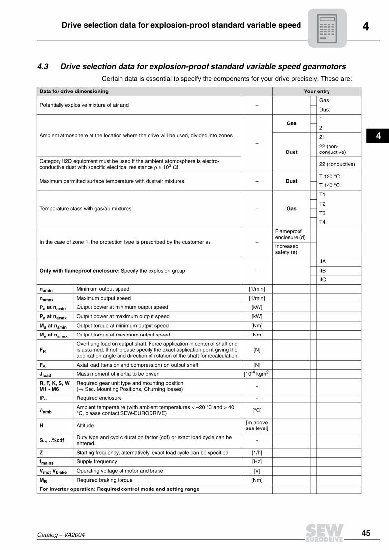
4.3 Drive selection data for explosion-proof standard variable speed gearmotorsCertain data is essential to specify the components for your drive precisely. These are:
Data for drive dimensioning Your entry
Potentially explosive mixture of air and –Gas
Dust
Ambient atmosphere at the location where the drive will be used, divided into zones–
Gas1
2
Dust
21
22 (non-conductive)
Category II2D equipment must be used if the ambient atomosphere is electro-conductive dust with specific electrical resistance ρ ≤ 103 Ω! 22 (conductive)
Maximum permitted surface temperature with dust/air mixtures – DustT 120 °C
T 140 °C
Temperature class with gas/air mixtures – Gas
T1
T2
T3
T4
In the case of zone 1, the protection type is prescribed by the customer as –
Flameproof enclosure (d)
Increased safety (e)
Only with flameproof enclosure: Specify the explosion group –
IIA
IIB
IIC
namin Minimum output speed [1/min]
namax Maximum output speed [1/min]
Pa at namin Output power at minimum output speed [kW]
Pa at namax Output power at maximum output speed [kW]
Ma at namin Output torque at minimum output speed [Nm]
Ma at namax Output torque at maximum output speed [Nm]
FR
Overhung load on output shaft. Force application in center of shaft end is assumed. If not, please specify the exact application point giving the application angle and direction of rotation of the shaft for recalculation.
[N]
FA Axial load (tension and compression) on output shaft [N]
Jload Mass moment of inertia to be driven [10-4 kgm2]
R, F, K, S, WM1 - M6
Required gear unit type and mounting position(→ Sec. Mounting Positions, Churning losses) -
IP.. Required enclosure -
ϑambAmbient temperature (with ambient temperatures < –20 °C and > 40 °C, please contact SEW-EURODRIVE) [°C]
H Altitude [m above sea level]
S.., ..%cdf Duty type and cyclic duration factor (cdf) or exact load cycle can be entered. -
Z Starting frequency; alternatively, exact load cycle can be specified [1/h]
fmains Supply frequency [Hz]
Vmot Vbrake Operating voltage of motor and brake [V]
MB Required braking torque [Nm]
For inverter operation: Required control mode and setting range

4 Project planning process for standard variable speed gearmotors
46 Catalog – VA2004
4.4 Project planning process for standard variable speed gearmotorsThe following flowchart displays a schematic view of the procedure for project planninga project incorporating a variable speed gear unit with a component on the input side.
Necessary information about the machine to be driven– Technical data and environmental conditions– Starting frequency– Travel cycle
↓
Calculation of the relevant application data– Static, dynamic and regenerative power– Speeds– Torques– Travel cycle
↓
Variable speed gearmotor selection– Definition of the variable speed gearmotor size, gear unit reduction ratio
and gear head unit type– Check for gear unit utilization (Ma max ≥ Ma (t))
↓
Calculation of the data on the output shaft– Output torque– Output power– Output speed– Overhung loads and axial forces
↓
Variable speed gear unit options– Monitoring functions (units, equipment)– Brake for VARIBLOC®
– Control heads– Indicator units– Centering shoulder (only VARIBLOC® with input shaft assembly)
↓
Motor options– Brake– Plug connector– TF temperature sensor monitoring
↓
Make sure that all requirements have been met.
In case of questions please contact SEW-EURODRIVE.

4Project planning notes for standard variable speed gearmotors
Catalog – VA2004 47
1
2
3
4
4.5 Project planning notes for standard variable speed gearmotorsThe selection of variable speed gear units depends on various parameters. The mostimportant project planning notes for VARIBLOC® and VARIMOT® are shown in below table.
Belt life The service factors fB and fT (→ Sec. "Service factors") can be used for determining theminimum life LnB (h) of the wide V-belt according to the following relationship:
Abrasive dust or aggressive ambient air shorten the service life. The service life isextended by having a reduced setting range and a low belt flexing frequency.
4.6 Efficiency of SEW gear unitsThe efficiency of gear units is mainly determined by the gearing and bearing friction.Keep in mind that the starting efficiency of a gear unit is always less than its efficiencyat operating speed. This factor is especially pronounced in the case of helical-worm gearunits.
R, F, K gear units The efficiency of helical, parallel shaft and helical-bevel gear units varies with thenumber of gear stages, between 94 % (3-stage) and 98 % (1-stage).
S gear units The gearing of helical-worm gear units produces a high proportion of sliding friction. Asa result, these gear units may have higher gearing losses than R, F or K gear units andthus be less efficient.
The efficiency depends on the following factors:
• Gear ratio of the helical-worm gear stage
Criterion VARIBLOC® (variable speed belt drive gear unit) VARIMOT® (variable speed friction disc gear unit)
Power ranges 0.25kW ... 45 kW 0.25kW ... 11 kW
Setting range1:3, 1:4, 1:5, 1:6, 1:7, 1:8 depending on the number of poles of the driving motor and the input power.
1:4, 1:5 depending on the number of poles of the driving motor and the input power.
Adjustment at standstill
Adjustment at standstill is not permitted because the belt tension is only adjusted automatically when the drive is running.
Adjustment at standstill is possible, however this should not be done too frequently in operation.
Load typeAlso suitable for variable loads (load shocks due to material feed, etc.), damping by the belt.
Only suitable for constant load (e.g. conveyor belts); load shocks can cause the friction ring to slip and lead to surface damage.
Adjustment options Handwheel or chain sprocket, electrical or hydraulic remote control.
Handwheel, electrical remote control.
Indicator unitsAnalog or digital indicator units, analog display with special scale is possible.
Analog or digital indicator units, analog display with special scale is possible, setting indicator on the housing.
Wear
The wide V-belt must be replaced after approx. 6000 h under rated load.The service life is considerably longer at lower loadings. The service life of the wide V-belt is reduced by higher ambient temperatures and harsher environmental conditions.
Low wear, it is not possible to provide specific information about replacement intervals.
LnB6000fB fT×----------------=

4 Efficiency of SEW gear units
48 Catalog – VA2004
• Input speed
• Gear unit temperature
Helical-worm gear units are designed as helical worm gear units which makes themsignificantly more efficient than straightforward worm gear units. The efficiency mayreach η < 0.5 if the worm gear stage has a very high ratio step.
Self-locking Retrodriving torques on helical-worm gear units produce a reverse efficiency of η' =-2 - 1/h, which is significantly less favorable than the forward efficiency h. The helical-worm gear unit is self-locking if the forward efficiency η ≤ 0.5. A few helical-worm gearunits with the largest gear ratio are statically self-locking, although not dynamically self-braking. Please contact SEW-EURODRIVE if you wish to make technical use of thebraking effect of self-locking charcteristics.
Run-in phase The tooth flanks of new helical-worm gear units are not yet completely smooth. That factmakes for a greater friction angle and less efficiency than during later operation. Thiseffect becomes more apparent the greater the gear ratio. Subtract the following valuesfrom the listed efficiency during the running-in phase:
The run-in phase usually lasts 24 hours. The helical-worm gear units achieve their listedrated efficiency values when:
• the gear unit has been run in completely,
• the gear unit has reached nominal operating temperature,
• the recommended lubricant has been filled in and
• the gear unit is working within the rated load range.
overhung loadDetermining overhung load
When determining the resulting overhung load, the type of transmission elementmounted on the shaft end must be considered. The following transmission elementfactors fZ also have to be considered for various transmission elements.
The overhung load exerted on the gear shaft is then calculated as follows:
Worm i range η reduction
1 start ca. 50 ... 280 ca. 12 %
2 start ca. 20 ... 75 ca. 6 %
3 start ca. 20 ... 90 ca. 3 %
4 start - -
5 start ca. 6 ... 25 ca. 3 %
6 start ca. 7 ... 25 ca. 2 %
Transmission element Transmission element factor fZ Comments
Gears 1.15 < 17 teeth
Chain sprockets 1.40 < 13 teeth
Chain sprockets 1.25 < 20 teeth
Narrow V-belt pulleys 1.75 Pre-tensioning influence
Flat belt pulleys 2.50 Pre-tensioning influence
Toothed belt pulleys 2.50 Pre-tensioning influence

4Efficiency of SEW gear units
Catalog – VA2004 49
1
2
3
4
Permitted overhung load
The basis for determining the permitted overhung loads is the computation of the ratedservice life LH10 of the anti-friction bearings (according to ISO 281). For specialoperating conditions, the permitted overhung loads can be determined with regard to themodified service life Lna on request.
The permitted overhung loads FRa for the output shafts of foot-mounted gear units witha solid shaft are listed in the selection tables. Contact SEW-EURODRIVE in case ofother versions.
The data refer to the radial force acting midway on the shaft end (with right-anglegear units on the A-side output). Worst case conditions have been assumed forthe force application angle α and the direction of rotation.
• Only 50 % of the FRa value specified in the selection tables is permitted in mountingposition M1 with wall attachment on the front face for K and S gear units.
• Foot and flange-mounted helical gear units (R..F): A maximum of 50 % of theoverhung load FRa specified in the selection tables in the case of torquetransmission via the flange mounting.
Higher permitted overhung loads
Higher output shaft loads are permitted if heavy duty bearings are installed, especiallywith R, F and K gear units. Exactly considering the force application angle α and thedirection of rotation also makes it possible to achieve a higher overhung load. ContactSEW in such cases.
Definition of force application
Force application is defined according to the following figure:
FR = Overhung load in N
Md = Torque in Nm
d0 = Mean diameter of the mounted transmission element in mm
fZ = Transmission element factor
02355DXXFigure 1: Definition of force application
FX = Permitted overhung load at point x [N]
FA = Permitted axial force [N]
α α
0° 0°
X
FX
FA

4 Efficiency of SEW gear units
50 Catalog – VA2004
Permitted axial forces
If there is no overhung load, then an axial force FA (tension or compression) on theoutput end amounting to 50 % of the overhung load given in the selection tables ispermitted.
• for helical gear units except for R..137... to R..167...
• for parallel shaft and helical-bevel gear units with solid shaft except for F97...
• for helical-worm gear units with solid shaft
Contact SEW-EURODRIVE for all other types of gear units and in the event ofsignificantly greater axial forces or combinations of overhung load and axial force.
Overhung load conversion on the output side for off-center force application
The permitted overhung loads given in the selection tables must be calculated using thefollowing formulae in the event of force application not in the center of the shaft end. Thesmaller of the two values FxL (according to bearing service life) and FxW (according toshaft strength) is the permitted value for the overhung load at point x. Note that thecalculations apply to Ma max.
FXL according to bearingservice life
FxW from theshaft strength
F = F •xL Raa
b + x[N]
F =xWc
f + x[N]
FRa = Permitted overhung load (x = l/2) for foot-mounted gear units according to the selection tables in [N]
x = Distance from the shaft shoulder to the force application point in [mm]
a, b, f = Gear unit constants for overhung load conversion [mm]
c = Gear unit constant for overhung load conversion [Nmm]
02356BXXFigure 2: Overhung load Fx for off-center force application
x
x
FRa
FRaFX FxL
d d
l
l/2

4Efficiency of SEW gear units
Catalog – VA2004 51
1
2
3
4
Gear unit constants for overhung load conversion
Values for types not listed are available on request.
Gear unit typea
[mm]b
[mm]c
[Nmm]f
[mm]d
[mm]I
[mm]
R27R37R47R57R67R77R87R97R107R137R147R167
106.5118137
147.5168.5173.7216.7255.5285.5343.5402450
81.593
107112.5133.5133.7166.7195.5215.5258.5297345
1.56 × 10⁵
1.24 × 10⁵
2.44 × 10⁵
3.77 × 10⁵
2.51 × 10⁵
3.97 × 10⁵
8.47 × 10⁵
1.19 × 10⁶
2.06 × 10⁶
6.14 × 10⁶
8.65 × 10⁶
1.26 × 10⁷
11.80
151800000
30330
25253035354050607090110120
505060707080
100120140170210210
RX57RX67RX77RX87RX97RX107
43.552.560.573.586.5
102.5
23.527.530.533.536.542.5
1.51 × 10⁵
2.42 × 10⁵
1.95 × 10⁵
7.69 × 10⁵
1.43 × 10⁶
2.47 × 10⁶
34.239.7
048.953.962.3
202530405060
40506080
100120
F37F47F57F67F77F87F97F107F127F157
123.5153.5170.7181.3215.8263350
373.5442.5512
98.5123.5135.7141.3165.8203280
288.5337.5407
1.07 × 10⁵
1.78 × 10⁵
5.49 × 10⁵
4.12 × 10⁵
7.87 × 10⁵
1.19 × 10⁶
2.09 × 10⁶
4.23 × 10⁶
9.45 × 10⁶
1.05 × 10⁷
00
320000000
2530354050607090110120
50607080
100120140170210210
K37K47K57K67K77K87K97K107K127K157
123.5153.5169.7181.3215.8252319
373.5443.5509
98.5123.5134.7141.3165.8192249
288.5338.5404
1.41 × 10⁵
1.78 × 10⁵
6.8 × 10⁵
4.12 × 10⁵
7.69 × 10⁵
1.64 × 10⁶
2.8 × 10⁶
5.53 × 10⁶
8.31 × 10⁶
1.18 × 10⁷
00
310000000
2530354050607090110120
50607080
100120140170210210
S37S47S57S67S77S87S97
118.5130150184224
281.5326.3
98.5105120149179
221.5256.3
6.0 × 10⁴
1.33 × 10⁵
2.14 × 10⁵
3.04 × 10⁵
5.26 × 10⁵
1.68 × 10⁶
2.54 × 10⁶
0000000
20253035456070
4050607090
120140

4 Permitted overhung loads of reduction gear units
52 Catalog – VA2004
4.7 Permitted overhung loads of reduction gear unitsR27 - R67
Gear unit type
Pm FRa[N]
[kW] ≤ 20[1/min]
40[1/min]
60[1/min]
90[1/min]
130[1/min]
180[1/min]
250[1/min]
350[1/min]
500[1/min]
700[1/min]
R27
0.25 4440 3640 3220 2840 2530 2280 2050 1840 1640 1470
0.37 4360 3600 3200 2830 2520 2270 2050 1840 1640 1470
0.55 3730 3440 3090 2750 2470 2240 2020 1820 1620 1460
0.75 795 3240 2960 2670 2410 2190 1990 1800 1610 1450
1.1 2950 2810 2570 2340 2140 1950 1770 1590 1430
1.5 775 2120 2400 2230 2060 1900 1730 1560 1410
R37
0.25 5960 5350 4710 4140 3680 3310 2970 2660 2370 2120
0.37 5900 5310 4680 4120 3660 3300 2970 2660 2360 2120
0.55 5570 5170 4590 4060 3620 3270 2940 2640 2350 2110
0.75 4400 4990 4470 3980 3570 3230 2910 2620 2340 2100
1.1 4790 4330 3890 3500 3180 2880 2600 2320 2090
1.5 3150 4110 3740 3400 3110 2830 2560 2300 2070
R47
0.25 6140 5480 4820 4230 3760 3380 3030 2720 2420 2160
0.37 6120 5460 4800 4220 3750 3370 3030 2710 2410 2160
0.55 6020 5340 4720 4170 3710 3350 3010 2700 2400 2150
0.75 5830 5190 4630 4100 3670 3310 2990 2680 2390 2150
1.1 5490 5030 4520 4030 3620 3280 2960 2670 2380 2140
1.5 4750 4330 3910 3530 3220 2920 2630 2360 2120
2.2 4430 4120 3760 3430 3150 2870 2600 2330 2100
3.0 3750 3520 3260 3020 2780 2530 2290 2070
R57
0.25 8010 6880 6040 5290 4690 4220 3780 3390 3010
0.37 8000 6860 6020 5280 4680 4210 3780 3380 3010
0.55 7940 6760 5950 5240 4650 4190 3760 3370 3000 2680
0.75 7840 6640 5870 5180 4620 4160 3740 3360 2990 2680
1.1 7670 6500 5780 5120 4570 4130 3720 3340 2980 2670
1.5 7250 6270 5630 5020 4500 4080 3690 3320 2960 2660
2.2 4050 6010 5450 4900 4420 4020 3640 3290 2940 2640
3.0 5550 5150 4700 4280 3920 3570 3230 2900 2620
4.0 3650 4800 4460 4120 3800 3490 3170 2860 2590
5.5 2880 4160 3910 3650 3380 3090 2810 2550
R67
0.25 9920 9940 9470 8290 7350 6600 5920 5300 4710
0.37 9880 9930 9410 8250 7320 6580 5910 5290 4700 4200
0.55 9810 9910 9340 8200 7290 6560 5890 5270 4690 4200
0.75 9640 9880 9260 8150 7250 6530 5870 5260 4680 4190
1.1 8900 9810 9120 8060 7180 6480 5840 5240 4660 4180
1.5 7540 9650 8960 7950 7110 6430 5800 5210 4640 4160
2.2 8900 8680 7760 6980 6340 5730 5160 4610 4140
3.0 7560 8360 7550 6830 6230 5650 5110 4570 4110
4.0 7940 7270 6640 6090 5550 5030 4520 4080
5.5 6880 6370 5890 5410 4930 4450 4030

4Permitted overhung loads of reduction gear units
Catalog – VA2004 53
1
2
3
4
R77 - R97
Gear unit type
Pm FRa[N]
[kW]≤ 20
[1/min]40
[1/min]60
[1/min]90
[1/min]130
[1/min]180
[1/min]250
[1/min]350
[1/min]500
[1/min]700
[1/min]
R77
0.25 13000 13000
0.37 13000 13000 11500 10100 8920 8010 7190 6430
0.55 13000 13000 11400 10000 8890 7990 7170 6420
0.75 12800 12900 11400 9970 8860 7970 7160 6410
1.1 12400 12700 11200 9900 8800 7930 7130 6390 5680 5090
1.5 11700 12500 11100 9810 8740 7890 7100 6370 5670 5080
2.2 9800 12200 10900 9660 8640 7810 7040 6330 5640 5060
3.0 11700 10600 9490 8520 7720 6980 6280 5610 5040
4.0 10400 10300 9260 8360 7610 6900 6220 5570 5010
5.5 9110 8940 8140 7450 6780 6140 5510 4970
7.5 7390 7830 7220 6620 6030 5430 4910
9.2 4960 7090 7050 6500 5940 5370 4860
11.0 5150 6660 6350 5830 5300 4810
R87
0.25 20000
0.37 20000
0.55 20000
0.75 20000 18500 16200 14200 12600 11300 10100 9080 8070
1.1 20000 18400 16100 14100 12500 11300 10100 9060 8060
1.5 20000 18200 16000 14100 12500 11200 10100 9050 8050
2.2 20000 17900 15800 14000 12400 11200 10100 9020 8020
3.0 19300 17700 15700 13800 12300 11100 10000 8980 8000
4.0 17100 17300 15400 13700 12200 11000 9950 8640 7670
5.5 16700 15000 13400 12000 10900 9860 8880 7930
7.5 15900 14500 13100 11800 10700 9740 8790 7860
9.2 15300 14100 12800 11600 10600 9640 8720 7820
11.0 13700 12500 11400 10500 9530 8640 7760
15.0 11800 10900 10100 9290 8470 7640
18.5 11200 10500 9830 9080 8320 7530
22.0 10700 10100 9540 8880 8170 7430
R97
0.25 28700
0.37 28700
0.55 28700
0.75 28600
1.1 28600
1.5 28500 23700 20800 18200 16200 14500 13000
2.2 28400 23500 20600 18100 16100 14500 13000 11600 10400
3.0 28100 23200 20500 18000 16000 14400 13000 11600 10300 9250
4.0 27600 22900 20300 17900 15900 14300 12900 11600 10300 9230
5.5 26100 22400 2000 17700 15800 14200 12800 11500 10300 9210
7.5 21900 21800 19500 17400 15600 14100 12700 11500 10200 9170
9.2 21300 19200 17200 15400 14000 12700 11400 10200 9140
11.0 20700 18800 16900 15200 13900 12600 11300 10100 9110
15.0 19500 18000 16300 14900 13600 12400 11200 10000 9030
18.5 17200 15900 14500 13300 12200 11100 9940 8970
22.0 16500 15400 14200 13100 12000 10900 9860 8910

4 Permitted overhung loads of reduction gear units
54 Catalog – VA2004
R107 - R137
Gear unit type
Pm FRa[N]
[kW]≤ 20
[1/min]40
[1/min]60
[1/min]90
[1/min]130
[1/min]180
[1/min]250
[1/min]350
[1/min]500
[1/min]700
[1/min]
R107
0.37 37000
0.55 36900
0.75 36800
1.1 36600
1.5 36400 29100
2.2 36000 28900
3.0 35600 28700
4.0 35000 28400 25100 22000 19600 17600 15800 14200
5.5 34200 28000 24800 21900 19500 17500 15800 14100
7.5 33100 27500 24400 21600 19300 17400 15700 14100 12500 11200
9.2 32300 27100 24100 21400 19200 17300 15600 14000 12500 11200
11.0 30200 26600 23800 21200 19000 17200 15500 14000 12500 11200
15.0 25500 23100 20700 18700 17000 15400 13900 12400 11100
18.5 24600 22500 20300 18400 16800 15200 13800 12300 11100
22.0 23700 21900 19900 18100 16600 15100 13600 12200 11000
30.0 20400 18900 17400 16100 14700 13400 12100 10900
37.0 19300 18200 16900 15700 14500 13200 11900
45.0 17200 16200 15200 14100 12900 11800
R137
0.37 61400
0.55 61400
0.75 61400
1.1 61400
1.5 61400 61400
2.2 61300 61400
3.0 61300
4.0 61100
5.5 60900
7.5 60400
9.2 60000
11.0 59300 60900 61200 61300 61400 58900 53800 48900
15.0 57500 60500 61000 61200 61300 58200 53200 48500 43800
18.5 55300 59900 60800 61100 61300 57600 52800 48200 43600
22.0 52500 59300 60500 61000 61200 57000 52400 47900 43400
30.0 57400 59600 60600 59600 55500 51300 47100 42900
37.0 55500 58800 60300 58200 54400 50500 46500 42500
45.0 51600 57500 59000 56100 52900 49400 45800 41900

4Permitted overhung loads of reduction gear units
Catalog – VA2004 55
1
2
3
4
R147 - R167
Gear unit type
Pm FRa[N]
[kW]≤ 20
[1/min]40
[1/min]60
[1/min]90
[1/min]130
[1/min]180
[1/min]250
[1/min]350
[1/min]500
[1/min]700
[1/min]
R147
0.37 74600
0.55 74600
0.75 74600
1.1 74600
1.5 74600
2.2 74500
3.0 74500 74600
4.0 74400 74600
5.5 74300 74500
7.5 74100 74500
9.2 73800 74400
11.0 73500 74300 74500 74500 74600 74600 74600 70800
15.0 72500 74100 74400 74500 74500 74600 74600 70500 63500
18.5 71300 73800 74200 74400 74500 74500 74600 70300 63400
22.0 69900 73500 74100 74400 74500 74500 74600 70000 63200
30.0 65300 72400 73600 74200 74400 74500 74500 69500 62800
37.0 60800 71400 73200 74000 74300 74400 74500 69000 62500
45.0 69700 72400 73600 74100 74400 74500 68500 62100
R167
1.5 120000
2.2 120000
3.0 120000
4.0 120000
5.5 120000
7.5 120000
9.2 120000
11.0 120000
15.0 120000
18.5 120000
22.0 120000
30.0 120000 120000 120000 120000 120000 114600 104500
37.0 120000 120000 120000 120000 120000 113900
45.0 120000 120000 120000 120000 120000 113000

4 Permitted overhung loads of reduction gear units
56 Catalog – VA2004
RX57-RX107
Gear unit type
Pm FRa[N]
[kW]100
[1/min]150
[1/min]200
[1/min]300
[1/min]450
[1/min]600
[1/min]800
[1/min]1000
[1/min]1200
[1/min]1600
[1/min]
RX57
0.25 4000 4240 4320 4360 4120 3720 3350 3000 2680 2400
0.37 3890 4200 4290 4340 4100 3700 3340 3000 2670 2390
0.55 4000 4170 4270 4010 3640 3290 2960 2650 2380
0.75 3720 4000 4170 3900 3560 3230 2920 2620 2360
1.1 3800 4040 3770 3460 3160 2870 2580 2330
1.5 3280 3560 3310 3050 2790 2530 2290
2.2 645 2460 3130 2920 2700 2460 2250
3.0 1130 2280 2540 2350 2170
RX67
0.25 5840 6030 6090 5710 5080 4580 4120 3690 3280 2940
0.37 5770 5990 6060 5680 5060 4560 4110 3680 3280 2940
0.55 5420 5850 5970 5570 4980 4510 4060 3650 3260 2920
0.75 4920 5640 5850 5430 4880 4430 4010 3610 3230 2900
1.1 5390 5700 5260 4770 4350 3950 3570 3200 2880
1.5 4920 5410 4990 4580 4220 3860 3500 3150 2850
2.2 3920 4680 4370 4060 3740 3420 3100 2810
3.0 2180 3990 3790 3550 3280 3000 2740
RX77
0.37 10000 10000 9280 8150 7240 6520 5850 5240 4660
0.55 10000 10000 9130 8050 7170 6470 5820 5220 4640 4160
0.75 10000 10000 8950 7930 7090 6400 5770 5190 4620 4140
1.1 10000 9730 8740 7790 6990 6330 5720 5150 4600 41301
1.5 9210 8390 7560 6830 6220 5640 5090 4560 4100
2.2 7080 7980 7290 6640 6080 5540 5020 4510 4060
3.0 4720 6820 6320 5850 5370 4900 4420 4000
4.0 3650 5690 5580 5180 4760 4330 3930
5.5 2620 4440 4930 4580 4200 2840
RX87
0.75 13000 12900 11400 10100 8960 8080 7270 6520 5800
1.1 13000 12600 11200 9940 8880 8020 7230 6490 5780 5180
1.5 12500 12200 10900 9750 8750 7920 7160 6440 5750 5160
2.2 11700 11700 10600 9520 8590 7810 7070 6380 5710 5130
3.0 4360 10800 10000 9130 8310 7610 6930 6280 5640 5080
4.0 7810 9330 8680 8000 7390 6770 6160 5550 5020
5.5 295 6300 8090 7600 7090 6560 6010 5450 4940
7.5 4820 7020 6680 6260 5800 5300 4840
9.2 3040 5680 5840 5500 5090 4690
11.0 3130 5410 5260 4930 4570
RX97
0.75 20000 16300 14400 12600 11200 10100 9080 8130 7240 6480
1.1 19600 16100 14200 12500 11200 10100 9040 8110 7220 6460
1.5 18900 15700 14000 12400 11000 9970 8980 8070 7190 6440
2.2 18000 15300 13700 12200 10900 9870 8910 8020 7150 6420
3.0 16500 14500 13200 11800 10700 9710 8790 7930 7090 6380
4.0 4190 13700 12600 11500 10400 9520 8660 7830 7020 6330
5.5 12500 11900 11000 10100 9270 8480 7700 6930 6260
7.5 4930 10800 10300 9580 8910 8220 7520 6810 6170
9.2 2880 8590 8890 8420 7860 7270 6630 6040
11.0 4490 8360 8030 7590 7070 6490 5950
15.0 5250 7590 7270 6840 6330 5830
18.5 2950 6070 6350 5980 5580
22.0 2780 5580 5680 5360

4Permitted overhung loads of reduction gear units
Catalog – VA2004 57
1
2
3
4
RX107
F37 - F67
Gear unit type
Pm FRa[N]
[kW]100
[1/min]150
[1/min]200
[1/min]300
[1/min]450
[1/min]600
[1/min]800
[1/min]1000
[1/min]1200
[1/min]1600
[1/min]
RX107
4.0 15600 15800 14700 13400 12200 11200 10200 9250 8300
5.5 2140 14300 13700 12700 11800 10900 9960 9070 8180
7.5 7010 12200 11800 11100 10400 9620 8820 8010 7270
9.2 3720 8470 11000 10600 10000 9350 8630 7870 7180
11.0 2850 9470 9990 9590 9040 8420 7720 7070
15.0 1230 7000 8650 8370 7930 7380 6830
18.5 1990 6380 7780 7510 7090 6610
22.0 2890 6560 7100 6800 6410
Type
Pm FRa[N]
[kW]≤ 10
[1/min]25
[1/min]40
[1/min]60
[1/min]90
[1/min]130
[1/min]170
[1/min]220
[1/min]280
[1/min]350
[1/min]420
[1/min]500
[1/min]650
[1/min]900
[1/min]
F37
0.25 4710 5420 5490 5110 4520 4030 3710 3410 3160 2940 2770 2620 2410 2170
0.37 5190 5410 4950 4410 3950 3650 3370 3120 2910 2750 2600 2390 2150
0.55 4710 5200 4740 4270 3860 3570 3310 3080 2880 2720 2580 2370 2140
0.75 3810 4840 4500 4110 3750 3490 3250 3030 2840 2690 2550 2350 2120
1.1 4170 4100 3850 3570 3350 3140 2940 2770 2630 2500 2310 2100
1.5 3640 3540 3350 3190 3010 2840 2690 2560 2440 2270 2070
F47
0.25 7940 8240 8270 7720 6790 6040 5540 5090 4710 4380 4120 3900
0.37 7250 8140 8240 7580 6700 5970 5490 5050 4680 4350 4100 3880
0.55 4710 7940 8160 7410 6580 5890 5420 5010 4640 4320 4080 3860 3550 3190
0.75 7600 7990 7210 6450 5800 5350 4950 4600 4290 4050 3830 3530 3180
1.1 6740 7500 6880 6230 5650 5240 4860 4530 4230 4000 3790 3500 3160
1.5 6910 6490 5970 5470 5100 4760 4440 4170 3950 3750 3460 3130
F57
0.25 10200 10400 10500 10100 8850 7850 7190 6600 6100 5670 5340 5040
0.37 10100 10400 10400 10100 8830 7830 7180 6600 6090 5660 5330 5040
0.55 9700 10300 10400 9940 8750 7780 7130 6560 6070 5640 5320 5020 4610
0.75 9080 10100 10300 9780 8640 7710 7080 6520 6040 5620 5290 5000 4590
1.1 8220 9880 10200 9610 8530 7630 7020 6470 6000 5590 5270 4980 4580
1.5 9470 9950 9330 8340 7490 6920 6400 5940 5540 5230 4950 4550 4100
2.2 8890 9670 8990 8110 7340 6800 6300 5860 5480 5180 4910 4520 4080
3.0 4370 8970 8410 7730 7070 6590 6150 5740 5380 5100 4840 4470
4.0 7980 7740 7280 6760 6360 5960 5600 5270 5000 4760 4410
5.5 6880 6710 6360 6050 5730 5410 5120 4880 4650 4330
F67
0.25 13000 13000 13000 13000 13000 13000 13000 12900 12000 11300 10700
0.37 13000 13000 13000 13000 13000 13000 13000 12900 12000 11200 10600
0.55 12800 13000 13000 13000 13000 13000 13000 12900 12000 11200 10600 10100 9340
0.75 12000 13000 13000 13000 13000 13000 13000 12800 12000 11200 10600 10100 9330
1.1 10200 13000 13000 13000 13000 13000 13000 12800 11900 11200 10600 10000 9300 8450
1.5 12600 13000 13000 13000 13000 13000 12700 11800 11100 10500 10000 9280 8440
2.2 11500 12800 13000 13000 13000 13000 12500 11700 11000 10500 9950 9230 8400
3.0 12100 12900 13000 13000 13000 12400 11600 10900 10400 9880 9180 8360
4.0 10800 12400 13000 13000 13000 12200 11400 10800 10300 9790 9110 8310
5.5 11300 12600 13000 12600 11900 11200 10600 10100 9670 9010 8240

4 Permitted overhung loads of reduction gear units
58 Catalog – VA2004
F77 - F97
Type
Pm FRa[N]
[kW]≤ 10
[1/min]25
[1/min]40
[1/min]60
[1/min]90
[1/min]130
[1/min]170
[1/min]220
[1/min]280
[1/min]350
[1/min]420
[1/min]500
[1/min]650
[1/min]900
[1/min]
F77
0.25 20000
0.37 20000 20000 20000 20000 20000 19600 18100 16700 15600 14600
0.55 19800 20000 20000 20000 20000 19500 18000 16700 15600 14600 13800
0.75 19600 20000 20000 20000 20000 19500 18000 16700 15500 14500 13800 13100
1.1 18900 19900 20000 20000 20000 19400 17900 16600 15500 14500 13700 13100 12100
1.5 17700 19800 20000 20000 20000 19300 17800 16600 15400 14500 13700 13000 12100 11000
2.2 14500 19300 19800 20000 20000 19100 17700 16400 15300 14400 13700 13000 12000 10900
3.0 18600 19600 19900 20000 18800 17500 16300 15200 14300 13600 12900 12000 10900
4.0 17300 19100 19700 19900 18600 17300 16100 15100 14200 13500 12800 11900 10900
5.5 14500 18100 19300 19800 18200 17000 15900 14900 14100 13400 12700 11800 10800
7.5 16100 18500 19000 17600 16600 15600 14700 13800 13200 12600 11700 10700
9.2 13900 17600 18400 17200 16200 15300 14500 13700 13100 12500 11600 10700
11.0 16400 17600 16700 15900 15000 14200 13500 12900 12400 11500 10600
F87
0.25 30000
0.37 30000 28700
0.55 30000 28400
0.75 29700 28200 24300 21400 18700 16600 15200 14000 12900 12000
1.1 29200 27700 24000 21200 18600 16600 15200 14000 12900 12000 11300
1.5 28500 27200 23700 21000 18500 16400 15100 13900 12900 12000 11300 10700 9780
2.2 27200 26300 23100 20600 18200 16300 15000 13800 12800 11900 11200 10600 9750
3.0 25300 25300 22500 20200 17900 16100 14800 13700 12700 11800 11200 10600 9710 8740
4.0 17500 23900 21700 19600 17600 15800 14600 13500 12600 11700 11100 10500 9660 8700
5.5 22000 20500 18800 17000 15500 14300 13300 12400 11600 11000 10400 9580 8650
7.5 19300 18800 17700 16300 14900 13900 13000 12200 11400 10800 10300 9480 8570
9.2 17300 17500 16800 15700 14500 13600 12800 12000 11300 10700 10200 9400 8520
11.0 16000 15800 15100 14100 13300 12500 11800 11100 10500 10000 9310 8450
15.0 12800 13700 13600 13100 12500 11900 11300 10700 10200 9780 9110 8310
18.5 11800 12300 12200 11900 11400 10900 10400 9960 9550 8930 8180
22.0 9910 11100 11400 11200 10900 10500 10100 9700 9330 8760 8060
F97
0.25 38100
0.37 37900
0.55 37800
0.75 37500
1.1 37200
1.5 36700 37700 34600 30500 26800 23800 21800 20100 18500
2.2 35800 37400 34100 30100 26600 23600 21700 20000 18500 17200 16200
3.0 34600 37100 33500 29800 26300 23500 21600 19900 18400 17100 16100 15300 14000 12600
4.0 32800 36600 32800 29200 26000 23200 21400 19700 18300 17000 16100 15200 14000 12600
5.5 29800 35300 31700 28500 25500 22900 21100 19500 18100 16900 16000 15100 13900 12500
7.5 32800 30100 27500 24800 22400 20800 19200 17900 16700 15800 15000 13800 12400
9.2 30900 29000 26700 24300 22100 20500 19000 17700 16600 15700 14900 13700 12400
11.0 28800 27600 25800 23700 21600 20200 18800 17500 16400 15600 14800 13600 12300
15.0 24000 24600 23800 22300 20700 19500 18200 17100 16100 15300 14500 13500 12200
18.5 22000 22100 21200 19900 18800 17800 16700 15800 15000 14300 13300 12100
22.0 19500 20400 20000 19100 18200 17300 16400 15500 14800 14100 13100 12000
4Permitted overhung loads of reduction gear units
Catalog – VA2004 59
1
2
3
4
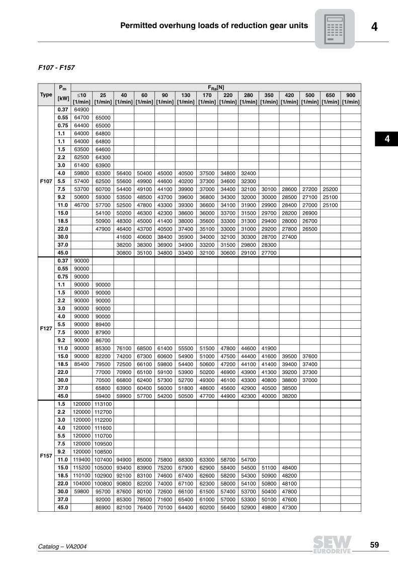
F107 - F157
TypePm FRa[N]
[kW]≤10
[1/min]25
[1/min]40
[1/min]60
[1/min]90
[1/min]130
[1/min]170
[1/min]220
[1/min]280
[1/min]350
[1/min]420
[1/min]500
[1/min]650
[1/min]900
[1/min]
F107
0.37 64900
0.55 64700 65000
0.75 64400 65000
1.1 64000 64800
1.1 64000 64800
1.5 63500 64600
2.2 62500 64300
3.0 61400 63900
4.0 59800 63300 56400 50400 45000 40500 37500 34800 32400
5.5 57400 62500 55600 49900 44600 40200 37300 34600 32300
7.5 53700 60700 54400 49100 44100 39900 37000 34400 32100 30100 28600 27200 25200
9.2 50600 59300 53500 48500 43700 39600 36800 34300 32000 30000 28500 27100 25100
11.0 46700 57700 52500 47800 43300 39300 36600 34100 31900 29900 28400 27000 25100
15.0 54100 50200 46300 42300 38600 36000 33700 31500 29700 28200 26900
18.5 50900 48300 45000 41400 38000 35600 33300 31300 29400 28000 26700
22.0 47900 46400 43700 40500 37400 35100 33000 31000 29200 27800 26500
30.0 41600 40600 38400 35900 34000 32100 30300 28700 27400
37.0 38200 38300 36900 34900 33200 31500 29800 28300
45.0 30800 35100 34800 33400 32100 30600 29100 27700
F127
0.37 90000
0.55 90000
0.75 90000
1.1 90000 90000
1.5 90000 90000
2.2 90000 90000
3.0 90000 90000
4.0 90000 90000
5.5 90000 89400
7.5 90000 87900
9.2 90000 86700
11.0 90000 85300 76100 68500 61400 55500 51500 47800 44600 41900
15.0 90000 82200 74200 67300 60600 54900 51000 47500 44400 41600 39500 37600
18.5 85400 79500 72500 66100 59800 54400 50600 47200 44100 41400 39400 37400
22.0 77000 70900 65100 59100 53900 50200 46900 43900 41300 39200 37300
30.0 70500 66800 62400 57300 52700 49300 46100 43300 40800 38800 37000
37.0 65800 63900 60400 56000 51800 48600 45600 42900 40500 38500
45.0 59400 59900 57700 54200 50500 47700 44900 42300 40000 38200
F157
1.5 120000 113100
2.2 120000 112700
3.0 120000 112200
4.0 120000 111600
5.5 120000 110700
7.5 120000 109500
9.2 120000 108500
11.0 119400 107400 94900 85000 75800 68300 63300 58700 54700
15.0 115200 105000 93400 83900 75200 67900 62900 58400 54500 51100 48400
18.5 110100 102900 92100 83100 74600 67400 62600 58200 54300 50900 48200
22.0 104000 100800 90800 82200 74000 67100 62300 58000 54100 50800 48100
30.0 59800 95700 87600 80100 72600 66100 61500 57400 53700 50400 47800
37.0 92000 85300 78500 71600 65400 61000 57000 53300 50100 47600
45.0 86900 82100 76400 70100 64400 60200 56400 52900 49800 47300

4 Permitted overhung loads of reduction gear units
60 Catalog – VA2004
K37 - K77
TypePm FRa[N]
[kW]≤10
[1/min]25
[1/min]40
[1/min]60
[1/min]90
[1/min]130
[1/min]170
[1/min]220
[1/min]280
[1/min]350
[1/min]420
[1/min]500
[1/min]650
[1/min]
K37
0.25 6020 6160 5400 4800 4240 3790 3480 3210 2970 2760 2610 2460 2260
0.37 5760 5160 4630 4130 3710 3420 3160 2930 2740 2580 2440 2250
0.55 5270 4850 4430 4000 3620 3350 3110 2890 2700 2550 2420 2230
0.75 4710 4500 4190 3840 3510 3270 3040 2840 2660 2520 2390 2210
1.1 3920 3810 3580 3330 3130 2940 2760 2590 2460 2340 2170
K47
0.25 7960 8250 8280 7730 6800 6050 5550 5100 4720 4380 4130
0.37 7310 8150 8240 7580 6700 5980 5490 5060 4680 4360 4110 3880
0.55 5740 7960 8170 7400 6580 5890 5430 5010 4650 4330 4080 3860 3550
0.75 7630 7960 7190 6440 5800 5350 4950 4600 4290 4050 3840 3530
1.1 6820 7450 6850 6210 5640 5230 4860 4530 4230 4000 3800 3500
1.5 6840 6440 5940 5450 5090 4750 4440 4160 3950 3750 3460
2.2 5650 5740 5480 5130 4840 4560 4290 4040 3850 3660 3400
3.0 4950 4940 4760 4560 4340 4120 3910 3730 3570
K57
0.25 9800 10000 10100 10100 8900 7900 7240 6650 6150 5710
0.37 9710 10000 10100 10100 8880 7880 7230 6640 6140 5700
0.55 9320 9880 9990 9980 8790 7820 7180 610 6110 5680 5350 5060
0.75 8740 9710 9900 9810 8680 7740 7120 6560 6070 5650 5330 5040
1.1 7620 9500 9780 9620 8550 7660 7050 6510 6030 5620 5300 5010
1.5 9100 9570 9300 8340 7510 6940 6420 5960 5570 5260 4980 4580
2.2 8550 9290 8930 8090 7340 6810 6320 5880 5500 5200 4930 4540
3.0 6100 8740 8290 7660 7040 6580 6140 5750 5390 5110 4850
4.0 7660 7550 7170 6700 6320 5940 5590 5270 5010 4770
5.5 6590 6530 6260 5980 5680 5380 5100 4870 4650
K67
0.25 13000 13000 13000 13000 13000 13000 13000 12900 12000
0.37 13000 13000 13000 13000 13000 13000 13000 12900 12000 11200
0.55 12800 13000 13000 13000 13000 13000 13000 12900 12000 11200 10600
0.75 12100 13000 13000 13000 13000 13000 13000 12800 11900 11200 10600
1.1 10300 13000 13000 13000 13000 13000 13000 12700 11900 11100 10600
1.5 12600 13000 13000 13000 13000 13000 12600 11800 11100 10500 10000
2.2 11600 12800 13000 13000 13000 13000 12500 11700 11000 10400 9930
3.0 12100 12900 13000 13000 13000 12300 11500 10900 10300 9850
4.0 10900 12400 13000 13000 12800 12100 11400 10700 10200 9750
5.5 11400 12600 13000 12400 11700 11100 10500 10000 9600
K77
0.25 20000 20000
0.37 20000 20000 20000 20000 20000 19600 18100 16700 15600
0.55 19800 20000 20000 20000 20000 19500 18000 16700 15600 14600
0.75 19600 20000 20000 20000 20000 19400 18000 16700 15500 14500 13800
1.1 18900 20000 20000 20000 20000 19300 17900 16600 15500 14500 13700 13100
1.5 17800 19800 20000 20000 20000 19200 17800 16500 15400 14500 13700 13000
2.2 14700 19400 19800 20000 20000 19000 17600 16400 15300 14400 13600 13000
3.0 18700 19600 19900 20000 18800 17500 16300 15200 14300 13600 12900
4.0 17400 19100 19700 19900 18400 17200 16100 15100 14200 13500 12800
5.5 14700 18200 19300 19500 18000 16900 15800 14900 14000 13300 12700
7.5 16300 18500 18600 17400 16400 15400 14600 13800 13100 12500
9.2 14200 17700 17900 16900 16000 15100 14300 13600 13000 12400
11.0 16600 17100 16300 15600 14800 14100 13400 12800 12300

4Permitted overhung loads of reduction gear units
Catalog – VA2004 61
1
2
3
4
K87 - K107
TypePm FRa[N]
[kW]≤10
[1/min]25
[1/min]40
[1/min]60
[1/min]90
[1/min]130
[1/min]170
[1/min]220
[1/min]280
[1/min]350
[1/min]420
[1/min]500
[1/min]650
[1/min]
K87
0.25 29100 29100
0.37 29100 29100
0.55 29000 29100
0.75 29000 29100 29100 27100 24100 21600 20000 18500 17200
1.1 28900 29000 29100 26900 23900 21500 19900 18500 17200
1.5 28700 29000 29000 26600 23800 21400 19800 18400 17100 16100 15200 14500
2.2 28300 28900 29000 26200 23500 21200 19700 18300 17100 16000 15200 14400
3.0 27800 28800 28400 25700 23200 21000 19500 18200 17000 15900 15100 14400
4.0 26800 28700 27500 25100 22800 20700 19300 18000 16800 15800 15000 14300
5.5 28000 26200 24300 22200 20300 19000 1800 16600 15700 14900 14200
7.5 25100 24400 23000 21400 19800 18600 17400 16400 15500 14700 14000
9.2 22800 23000 22100 20800 19300 18200 17200 16200 15300 14600 13900
11.0 21400 21000 20000 18800 17800 16900 16000 15100 14400 13800
15.0 17800 18700 18500 17700 17000 16200 15400 14700 14100 13500
18.5 16600 17100 16800 16300 15700 15000 14300 13800 13300
22.0 14600 15700 15900 15600 15100 14600 14000 13500 13000
K97
0.25 40000 40000
0.37 40000 40000
0.55 40000 40000
0.75 40000 40000
1.1 40000 40000
1.5 40000 40000 39800 35500 31600 28400
2.2 40000 40000 39200 35100 31400 28300 26200
3.0 40000 40000 38600 34700 31100 28100 26000 24200 22500 21100 20000
4.0 40000 40000 37800 34200 30700 27800 25800 24000 22400 21000 19900
5.5 40000 40000 36700 33400 30200 27500 25500 23800 22300 20900 19800
7.5 37700 35000 32300 29500 27000 25200 23500 22000 20700 19700
9.2 35700 33800 31500 28900 26600 24900 23300 21800 20600 19600
11.0 33400 32300 30500 28300 26100 24500 23000 21600 20400 19400
15.0 28300 29200 28400 26900 25200 23800 22400 21200 20000 19100
18.5 26400 26600 25700 24300 23100 21900 20800 19700 18900
22.0 23700 24800 24500 23500 22500 21500 20400 19400 18600
K107
0.37 65000
0.55 65000 65000
0.75 65000 65000
1.1 65000 65000
1.5 65000 65000
2.2 65000 65000
3.0 65000 64500
4.0 65000 63400 56100 50200 44900 40400 37400 34700 32400
5.5 65000 61900 55200 49600 44500 40100 37200 34600 32200
7.5 65000 59800 53800 48700 43900 39700 36900 34300 32100 30100 28500
9.2 65000 58200 52800 48000 43400 39400 36700 34100 31900 30000 28400
11.0 60800 56300 51600 47300 42900 39100 36400 33900 31700 29800 28300
15.0 52200 49100 45500 41700 38300 35800 33500 31400 29500 28100
18.5 48500 46800 44000 40700 37600 35200 33000 31100 29300 27900
22.0 45000 44600 42600 39800 36900 34700 32600 30700 29000 27600
30.0 39100 38900 37300 35200 33400 31700 30000 28400
37.0 35200 36300 35600 34000 32500 30900 29400
45.0 29500 32700 33200 32300 31200 29900 28600

4 Permitted overhung loads of reduction gear units
62 Catalog – VA2004
K127 - K157
TypePm FRa[N]
[kW]≤10
[1/min]25
[1/min]40
[1/min]60
[1/min]90
[1/min]130
[1/min]170
[1/min]220
[1/min]280
[1/min]350
[1/min]420
[1/min]500
[1/min]650
[1/min]
K127
0.37 82900
0.55 82900
0.75 82900
1.1 82800 82900
1.5 82800 82900
2.2 82800 82900
3.0 82700 82800
4.0 82600 82800
5.5 82500 82800
7.5 82100 82700
9.2 81800 82700
11.0 81400 82600 75300 67900 61000 55200 51200 47600
15.0 80100 80500 73100 66500 60100 54500 50700 47200 44100 41400
18.5 76000 77500 71200 65200 59200 53900 50300 46900 43900 41200
22.0 116600 74500 69300 64000 58400 53400 49800 46600 43600 41000
30.0 67100 64700 60900 56400 52000 48800 45700 42900 40500
37.0 61900 61400 58700 54900 51000 48000 45100 42500
45.0 54500 56800 55700 52900 49500 46900 44300 41800
K157
1.5 116600
2.2 116600
3.0 116600 113600
4.0 116500 112900
5.5 116400 111900
7.5 116200 110600 97300
9.2 116000 109500 96600
11.0 115700 108300 95900
15.0 114900 103400 92800
18.5 114000 103400 92800
22.0 113000 101100 31400
30.0 95500 87900 80600 73200 66700 62100
37.0 91500 85400 78900 72100 65900 61500
45.0 85900 81900 76600 70500 64800 60700

4Permitted overhung loads of reduction gear units
Catalog – VA2004 63
1
2
3
4
S37 - S77
TypePm FRa[N]
[kW]≤10
[1/min]30
[1/min]50
[1/min]70
[1/min]100
[1/min]1300
[1/min]160
[1/min]200
[1/min]250
[1/min]400
[1/min]
S37
0.25 3000 3000 3000 2990 2720 2530 2380 2230 2090 1810
0.37 82900 3000 2930 2760 2560 2410 2290 2150 2030 1770
0.55 82900 2540 2480 2350 2250 2150 2050 1950 1720
0.75 82800 82900 2160 2130 2070 2010 1930 1850 1670
1.1 82800 82900 1560 1780 1770 1740 1700 1570
S47
0.25 5570 5630 4900 4460 4010 3700 3470 3240 3020 2610
0.37 5220 5230 4650 4270 3880 3610 3400 3180 2970 2580
0.55 82600 4740 4350 4050 3720 3490 3300 3100 2910 2540
0.75 82500 4180 4010 3800 3540 3340 3190 3020 2840 2490
1.1 82100 82700 3450 3400 3260 3120 3000 2860 2730 2420
1.5 81800 82700 2920 2920 2860 2780 2690 2580 2340
S57
0.25 8210 8290 7940 7160 6400 5890 5510 5130 4770 4100
0.37 8010 8240 7730 7010 6300 5810 5450 5080 4730 4080
0.55 7600 8130 7480 6820 6160 5710 5370 5020 4680 4040
0.75 6900 7970 7200 6620 6020 5590 5270 4940 4620 4010
1.1 7280 6730 6280 5770 5400 5120 4820 4530 3950
1.5 6370 6180 5880 5490 5190 4940 4670 4410 3880
S67
0.25 10700 10600 9080 8170 7290 6700 6270 5830 5430
0.37 10600 10300 8900 8050 7200 6640 6220 5790 5390 4640
0.55 10400 9990 8680 7890 7100 6550 6150 5740 5350 4610
0.75 9990 9590 8440 7710 6970 6460 6070 5680 5300 4580
1.1 9030 8940 8040 7420 6760 6300 5950 5580 5220 4530
1.5 8170 7580 7080 6520 6110 5790 5460 5130 4470
2.2 6850 6770 6500 6110 5790 5530 5240 4960 4370
3.0 5860 5840 5650 5430 5230 5000 4760 4250
4.0 3530 4980 5040 4960 4850 4690 4510 4100
5.5 2020 3700 4300 4310 4260 4160 3870
S77
0.37 16000 15400 13200 11800 10600 9700 9070 8440 7850
0.55 16000 15200 13000 11700 10500 9630 9020 8400 7820 6720
0.75 16000 14900 12800 11600 10400 9560 8960 8350 7780 6990
1.1 16000 14400 12500 11400 10200 9450 8870 8270 7720 6660
2.2 13800 12800 11500 10700 9730 9070 8560 8030 7520 6530
3.0 5660 11600 10800 10200 9370 8790 8330 7860 7380 6450
4.0 9320 9940 9500 8910 8430 8040 7620 7200 6330
5.5 3600 7790 8590 8270 7930 7630 7280 6930 6170
7.5 2770 5430 7150 7220 7050 6820 6550 5940
9.2 2650 5090 6250 6610 6460 6270 5750
11.0 2790 4400 5310 6020 5940 5540

4 Permitted overhung loads of reduction gear units
64 Catalog – VA2004
S87 - S97
TypePm FRa[N]
[kW]≤10
[1/min]30
[1/min]50
[1/min]70
[1/min]100
[1/min]1300
[1/min]160
[1/min]200
[1/min]250
[1/min]400
[1/min]
S87
0.75 30000 30000 30000 27700 25000 23200 21800 20500 19200
1.1 30000 30000 30000 27600 24900 23100 21700 20400 19100 16700
1.5 29900 30000 29900 27300 24700 23000 21600 20300 19000 16600
2.2 29600 30000 29400 26900 24500 22800 21500 20200 18900 16500
3.0 29200 29900 28800 26500 24100 22500 21300 20000 18800 16500
4.0 28600 29700 27900 25900 23700 22200 21000 19800 18600 16400
5.5 21600 29100 26800 25000 23100 21700 20600 19500 18400 16200
7.5 26400 25100 23800 22300 21100 20100 19100 18100 16000
9.2 22200 23900 22900 21600 20600 19700 18800 17800 15800
11.0 13700 22400 21900 20900 20000 19200 18400 17500 15700
15.0 13700 19600 19300 18800 18200 17600 16800 15300
18.5 3010 13300 17900 17700 17300 16800 16300 14900
22.0 6070 14500 16600 16500 16200 15700 14500
S97
1.5 39900 40000 37700 34300 30900 28700
2.2 39800 40000 37200 33900 30700 28500 26900 25200 23600
3.0 39600 39900 36700 33600 30400 28300 26700 25100 23500 20600
4.0 39200 39800 36000 33000 30100 28000 26500 24900 23400 20400
5.5 38500 39000 35000 32300 29600 27700 26200 24700 23200 20400
7.5 32800 36700 33600 31300 28900 27100 25800 24300 22900 20200
9.2 21400 35000 32600 30600 28400 26700 25400 24100 22700 20100
11.0 33000 31400 29700 27800 26200 25100 23800 22500 19900
15.0 26100 28700 27800 26400 25200 24200 23100 22000 19600
18.5 13500 26400 26200 25200 24300 23400 22500 21500 19300
22.0 21400 24600 24100 23400 22700 21900 21000 19000

4RM gear units
Catalog – VA2004 65
1
2
3
4
4.8 RM gear unitsProject planning You must take account of the higher overhung and axial loads when planning projects
with RM helical gear units with extended bearing housing. Observe the following projectplanning procedure:
M = F • XB R
FR
a
Aa
M = Output torqueF = Permitted axial load
Start of ProjectPlanning
Determine the requirements of theapplication
• Performance• Torque• Output speed• Overhung load (FR) / axial load (Fa)• Lever arm (x-dimension)
Select minimum service factors, e.g.:•
•
ffBmin
= 1.5 for L10h
10 000 h
Bmin= 2.0 for L
10h25 000 h
all other requirements on request
Select gear-unit size based onminimum service factor:
fBmin
fB (gear unit)
Check overhung load (bearing /shaft)?FR FXL= FRa • a/(x+b)
Check overhung load (flange)?FR FXF= c F /(FF+x)
Select next largergear unit
yes
no
no
Check axial load?Fa FAa
no
yesno
Special solutionon request from SEW
yesyes
x-dimension < 500mm?
yes
no
(FR•x/FAa)< 100 yes
no
Check connection dimensions
Determine additional features required:• gear unit with double seal• dry-well-version (special feature)• leakage sensor (special feature)• relubrication of bearings (special feature)
yesAdditional featuresnecessary?
End ofPoject Planning
no
a = Conversion factor from data tableb = Conversion factor from data tablec F = Gear-unit constants from data tableFa = Axial loads during operationFF = Gear-unit constants from data tableFR = Overhung loads during operationFRa = Permitted overhung load (at x = 1000 mm) from data tableFXF = Permitted overhung load on the housing (flange tensile strength)
FXL = Permitted overhung load according tobearing service lifex = Distance between force application and shaft shoulder
Select next largergear unit
F /M > 3aa

4 RM gear units
66 Catalog – VA2004
Permitted overhung loads and axial forces
The permitted overhung loads FRa and axial loads FAa are specified for various servicefactors fB and nominal bearing service life LH10.
fBmin = 1.5 / LH10 = 10 000 h
fBmin = 2.0 / LH10 = 25,000 h
na [1/min]
< 16 16-25 26-40 41-60 61-100 101-160 161-250 251-400
RM57FRa [N] 400 400 400 400 400 405 410 415
FAa [N] 18800 15000 11500 9700 7100 5650 4450 3800
RM67FRa [N] 575 575 575 580 575 585 590 600
FAa [N] 19000 18900 15300 11900 9210 7470 5870 5050
RM77FRa [N] 1200 1200 1200 1200 1200 1210 1210 1220
FAa [N] 22000 22000 19400 15100 11400 9220 7200 6710
RM87FRa [N] 1970 1970 1970 1970 1980 1990 2000 2010
FAa [N] 30000 30000 23600 18000 14300 11000 8940 8030
RM97FRa [N] 2980 2980 2980 2990 3010 3050 3060 3080
FAa [N] 40000 36100 27300 20300 15900 12600 9640 7810
RM107FRa [N] 4230 4230 4230 4230 4230 4230 3580 3830
FAa [N] 48000 41000 30300 23000 18000 13100 9550 9030
RM137FRa [N] 8710 8710 8710 8710 7220 5060 3980 6750
FAa [N] 70000 70000 70000 57600 46900 44000 35600 32400
RM147FRa [N] 11100 11100 11100 11100 11100 10600 8640 10800
FAa [N] 70000 70000 69700 58400 45600 38000 32800 30800
RM167FRa [N] 14600 14600 14600 14600 14600 14700 - -
FAa [N] 70000 70000 70000 60300 45300 36900 - -
na [1/min]
< 16 16-25 26-40 41-60 61-100 101-160 161-250 251-400
RM57FRa [N] 410 410 410 410 410 415 415 420
FAa [N] 12100 9600 7350 6050 4300 3350 2600 2200
RM67FRa [N] 590 590 590 595 590 595 600 605
FAa [N] 15800 12000 9580 7330 5580 4460 3460 2930
RM77FRa [N] 1210 1210 1210 1210 1210 1220 1220 1220
FAa [N] 20000 15400 11900 9070 6670 5280 4010 3700
RM87FRa [N] 2000 2000 2000 2000 2000 1720 1690 1710
FAa [N] 24600 19200 14300 10600 8190 6100 5490 4860
RM97FRa [N] 3040 3040 3040 3050 3070 3080 2540 2430
FAa [N] 28400 22000 16200 11600 8850 6840 5830 4760
RM107FRa [N] 4330 4330 4330 4330 4330 3350 2810 2990
FAa [N] 32300 24800 17800 13000 9780 8170 5950 5620
RM137FRa [N] 8850 8850 8850 8830 5660 4020 3200 5240
FAa [N] 70000 59900 48000 37900 33800 31700 25600 23300
RM147FRa [N] 11400 11400 11400 11400 11400 8320 6850 8440
FAa [N] 70000 60600 45900 39900 33500 27900 24100 22600
RM167FRa [N] 15100 15100 15100 15100 15100 13100 - -
FAa [N] 70000 63500 51600 37800 26800 23600 - -

4RM gear units
Catalog – VA2004 67
1
2
3
4
Conversion factors and gear unit constants
The following conversion factors and gear unit constants apply to calculating thepermitted overhung load FxL at point x ¼ 1000 mm for RM gear units:
Additional weights of RM gear units
Gear unit type a b cF (fB = 1.5) cF (fB = 2.0) FF
RM57 1047 47 1220600 1260400 277
RM67 1047 47 2047600 2100000 297.5
RM77 1050 50 2512800 2574700 340.5
RM87 1056.5 56.5 4917800 5029000 414
RM97 1061 61 10911600 11124100 481
RM107 1069 69 15367000 15652000 554.5
RM137 1088 88 25291700 25993600 650
RM147 1091 91 30038700 31173900 756
RM167 1089.5 89.5 42096100 43654300 869
Type Additional weight in addition to RF, related to the smallest RF flange∆m [kg]
RM57 12.0
RM67 15.8
RM77 25.0
RM87 29.7
RM97 51.3
RM107 88.0
RM137 111.1
RM147 167.4
RM167 195.4
4 Standard variable speed gearmotor selection
68 Catalog – VA2004
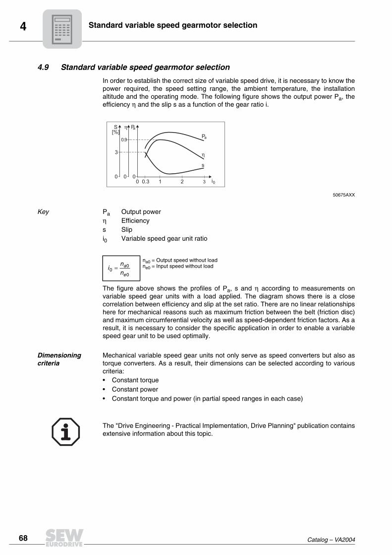
4.9 Standard variable speed gearmotor selection
In order to establish the correct size of variable speed drive, it is necessary to know thepower required, the speed setting range, the ambient temperature, the installationaltitude and the operating mode. The following figure shows the output power Pa, theefficiency η and the slip s as a function of the gear ratio i.
50675AXX
Key Pa Output powerη Efficiencys Slipi0 Variable speed gear unit ratio
The figure above shows the profiles of Pa, s and η according to measurements onvariable speed gear units with a load applied. The diagram shows there is a closecorrelation between efficiency and slip at the set ratio. There are no linear relationshipshere for mechanical reasons such as maximum friction between the belt (friction disc)and maximum circumferential velocity as well as speed-dependent friction factors. As aresult, it is necessary to consider the specific application in order to enable a variablespeed gear unit to be used optimally.
Dimensioning criteria
Mechanical variable speed gear units not only serve as speed converters but also astorque converters. As a result, their dimensions can be selected according to variouscriteria:• Constant torque• Constant power• Constant torque and power (in partial speed ranges in each case)
The "Drive Engineering - Practical Implementation, Drive Planning" publication containsextensive information about this topic.
0 1 2 3
η
000
3
0.3 i0
S[%]
0.9Pa
Pa
η
s
na0 = Output speed without loadne0 = Input speed without load

4Service factors
Catalog – VA2004 69
1
2
3
4
Selection according to the selection tables
Selecting a variable speed gear unit according to the information in the selection tablesmeans that its capabilities will be optimally exploited. The reduction gear unit must beconfigured so the maximum occurring output torques can be transmitted.If you do not want to fully exploit the available setting range of the variable speed gearunit, it is a good idea to position the speed range to be used at the top end of the overallspeed range since this gives better efficiency. The slip of the variable speed gear unit isat its lowest in the top speed range and the transmissible power is at its largest.
50655AXXFigure 3: Characteristic values of the variable speed gear unit (simplified representation)
Key Pa max Maximum output power (based on experiment)Pa1 Minimum output power at na1Pa2 Maximum output power at na2na1 Minimum output speedna2 Maximum output speedMa max Maximum output torque of the variable speed gear unitMa1 Output torque at na1Ma2 Output torque at na2
4.10 Service factorsIt is essential to know exactly what the drive application is in order to select the correctsize and type of drive. The operating conditions of the driven machine are representedby its duty cycle. Precise project planning work on the basis of the duty cycle demandsextensive calculations to be performed. As a result, the effects of the driven machine onthe gear unit and the variable speed gear unit are represented to an adequate degreeof accuracy by the service factor fB.
Service factor fB for load type
A service factor of 0.8 fB can be expected for a daily operating time of 2 hours.
0 00 0
Pa Ma
nana2na1 nana2na1
Pa2
Ma1
Ma2
Pa1
Pa max
Ma max
Load type fB Notes on Repair Procedure Examples
I 1.0 Uniform, smooth operation Fans, light conveyor belts, filling machines
II 1.25 Non-uniform operation with medium shocks
Hoists, balancing machines, crane trolleys
III 1.5 Highly non-uniform operation with powerful shocks
Heavy mixers, roller tables, punching machinery, stone crushers

4 Service factors
70 Catalog – VA2004
Factor fT at elevated ambient temperature
The load on the variable speed gear unit must be reduced at elevated ambienttemperature. The following diagram shows the required factor fT at elevated ambienttemperature Jamb.
00637BXXThe variable speed gear unit must be selected for the factor f = fB x fT larger than theoriginal calculation.
Special considerations for helical-worm gear units
With helical-worm gear units, it is necessary to take account of the service factor fB and,in addition, the influence of ambient temperature above 20 °C in terms of the load typeI, II and III (service factor fB1) as well as the cyclic duration factor (service factor fB2).
The additional service factors fB1 and fB2 can be determined by referring to the followingdiagrams. The load type is taken into consideration in fB1 in the same way as in fB.
00657BXX
The cyclic duration factor (cdf) is calculated using the following formula:
Contact SEW-EURODRIVE in case of temperatures below –20 °C (→ fB1).
The total service factor for a variable speed gearmotor in conjunction with a helical-wormgear unit is calculated as follows:
In this case, the larger of the two factors fT and fB1 is used for fB3.
0 20 40 600
1
2
3
°C
A B
fT
ϑU
A = VARIBLOCB = VARIMOT
®
®
fBtot = fB • fB2 • fB3
fB2
-20 0-10 20 40 6020 8030 100 %ED40 50°C
fB1
1.0 0.6
1.2 0.8
1.4 1.0
1.6
1.8
(III)
(II)
(I)
ED (%) =Time under load in min/h
60• 100

4Service factors
Catalog – VA2004 71
1
2
3
4
Starting frequency of variable speed gear units
Variable speed gearmotors are designed for continuous operation. Variable speeddrives with a high starting frequency are preferably designed as electronically controlledAC or DC drives.Note the following points for the special application of increased starting frequency:VARIBLOC® and VARIMOT® variable speed gear units will operate reliably and can beexpected to have a normal service life even given frequent load variations. Themaximum permitted number of starts is higher than that of the particular motor. Theadditional mass moment of inertia JZ to be accelerated by the motor is calculated usingthe following equation:
Key JZ [kgm2] Mass moment of inertia to be acceleratedJ1 [kgm2] Mass moment of inertia of the driving variable pulley or drive diskna [1/min] Output speed in the range na1 to na2 (na2 = most unfavorable speed
setting)nn [1/min] Rated speed of the motork Coefficient according to tableiG Ratio of the reduction gear unit on the output end (if there is no reduction
gear unit: iG = 1)Jext [kgm2] External mass moment of inertia
JZ J1
na2
nn2
--------- k J1 iG2 Jext+••( )•+=
Variable speed gear unitType
J1[10-4 kgm2]
k
VU/VZ01 12.52 1.1
VU/VZ11 29.78 1.1
VU/VZ21 39.72 1.22
VU/VZ31 209.65 1.1
VU/VZ41 456.48 1.6
VU51 917.94 1.56
VU6 2529 2.1
D/DF16 23 0.77
D/DF26 74 0.84
D/DF36 280 1.08
D/DF46 597 1.21

4 Protection and monitoring of standard variable speed gearmotors
72 Catalog – VA2004
4.11 Protection and monitoring of standard variable speed gearmotors
The WS option described in this section is not available for explosion-proof variablespeed gearmotors.
Overload protection
The motor protection system, regardless of what type is installed, does not protect thegear units connected to the motor output. An adapter with a torque limiting coupling (AR)can be used with variable speed gear units to limit the mechanical torque and protectthe gear stages connected on the output end.
Slip monitor /WS
Connection The encoder is connected to the monitor using a 2 or 3-core cable (depending on theencoder type).
• Maximum cable length: 500 m with a line cross section of 1.5 mm2
• Standard incoming cable: 3-core / 2 m
• Route the signal lines separately (not in multicore cables) and shield them ifnecessary
• Enclosure: IP40 (terminals IP20)
• Operating voltage: 220 VAC or 24 VDC
• Maximum switching capability of the output relay: 6 A (250 VAC)
52262AXXFigure 4: Adapter with torque limiting coupling and slip monitor /WS
[1] Trigger cam[2] Encoder (adapter)[3] Driving disc[4] Friction ring pads[5] Cup springs
[6] Slotted round nut[7] Friction hub[8] Slip monitor /WS[9] Encoder IG
22 23 24
A1 A2
19
21 3 4 5 6
7 8 9 10 11 12
13 14 15 16 17 18
20 21
[1] [2] [3] [4] [5] [6] [7] [8] [9]
4Protection and monitoring of standard variable speed gearmotors
Catalog – VA2004 73
1
2
3
4
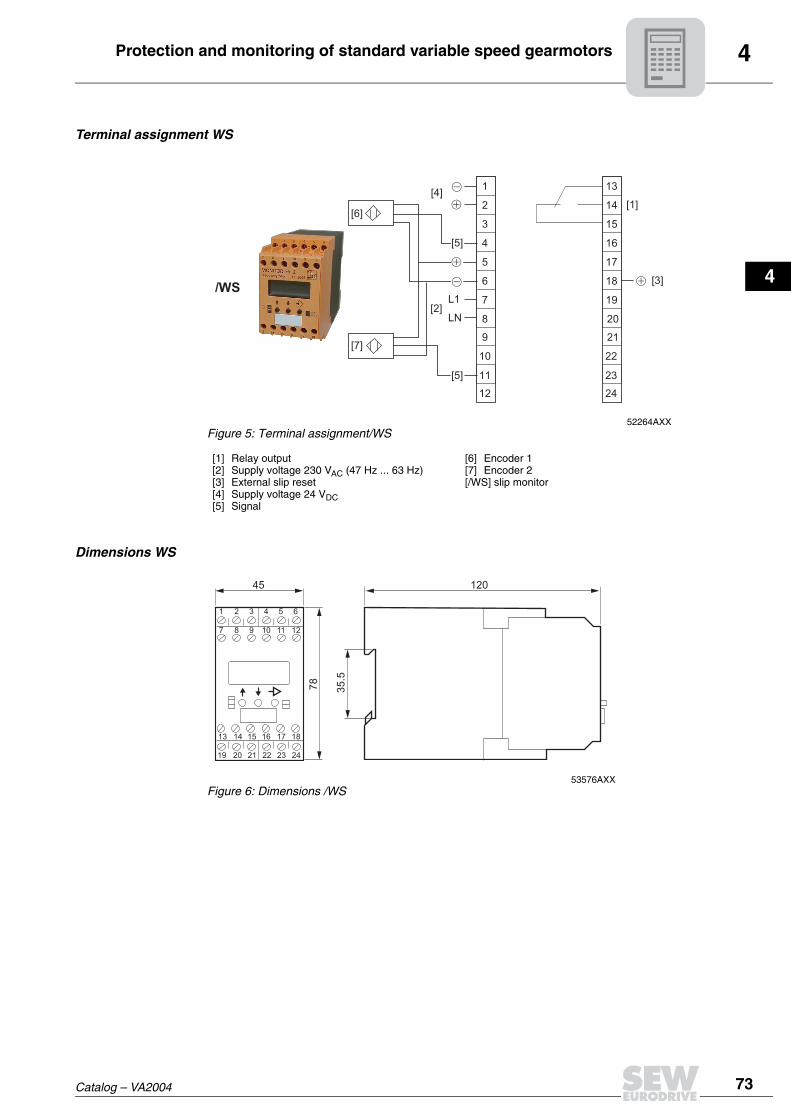
Terminal assignment WS
Dimensions WS
52264AXXFigure 5: Terminal assignment/WS
[1] Relay output[2] Supply voltage 230 VAC (47 Hz ... 63 Hz)[3] External slip reset[4] Supply voltage 24 VDC[5] Signal
[6] Encoder 1[7] Encoder 2[/WS] slip monitor
1
2
3
4
5
6
7
8
9
10
11
12
[6]
[4]
[7]
13
14
15
16
17
18
19
20
21
22
23
24
[5]
[2]
[5]
L1
LN
[1]
[3]/WS
53576AXXFigure 6: Dimensions /WS
1 2 3 4 5 6
7 8 9 10 11 12
19 20 21 22 23 24
13 14 15 16 17 18
45 120
78
35.5

4 VARIBLOC® options
74 Catalog – VA2004
4.12 VARIBLOC® optionsStandard VARIBLOC®
52300AXX
[12]
[11]
[10]
[9]
[8]
[7]
[1]
[2]
[3]
[4]
[5]
[6]
[1] Brake BM(G) (with tachogenerator IG)[2] Bearing cover[3] Rightangled tachometer TW[4] AC tachogenerator GW[5] Axial tachogenerator TA[6] Tachogenerator IG[7] Control head with handwheel and setting indicator HS[8] Hydraulic setting unit HY[9] Electromechanical remote speed control EF[10] Control head with hand wheel H / with exposed shaft end NV[11] Front adjustment with chain sprocket[12] Front adjustment with handwheel (standard version)

4VARIBLOC® options
Catalog – VA2004 75
1
2
3
4
Explosion-proof VARIBLOC®
53769AXX
[1] Driving motor[2] Bearing cover with M12x1 tapped hole (standard equipment)[3] Rightangle tachometer TW[4] Axial tachogenerator TA[5] Voltage encoder IGEX[6] Control head with handwheel and setting indicator HS[7] Control head with hand wheel H (standard type) / with exposed shaft end NV
[7]
[6]
[2]
[1]
[3]
[4]
[5]
4 VARIBLOC® options
76 Catalog – VA2004
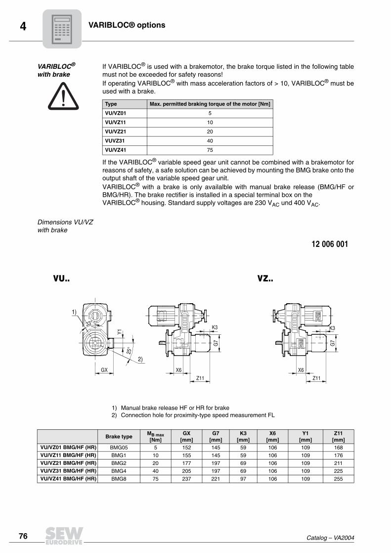
VARIBLOC® with brake
If VARIBLOC® is used with a brakemotor, the brake torque listed in the following tablemust not be exceeded for safety reasons!If operating VARIBLOC® with mass acceleration factors of > 10, VARIBLOC® must beused with a brake.
If the VARIBLOC® variable speed gear unit cannot be combined with a brakemotor forreasons of safety, a safe solution can be achieved by mounting the BMG brake onto theoutput shaft of the variable speed gear unit.VARIBLOC® with a brake is only availalble with manual brake release (BMG/HF orBMG/HR). The brake rectifier is installed in a special terminal box on the VARIBLOC® housing. Standard supply voltages are 230 VAC und 400 VAC.
Dimensions VU/VZwith brake
1) Manual brake release HF or HR for brake2) Connection hole for proximity-type speed measurement FL
Type Max. permitted braking torque of the motor [Nm]
VU/VZ01 5
VU/VZ11 10
VU/VZ21 20
VUVZ31 40
VU/VZ41 75
Brake typeMB max[Nm]
GX[mm]
G7[mm]
K3[mm]
X6[mm]
Y1[mm]
Z11[mm]
VU/VZ01 BMG/HF (HR) BMG05 5 152 145 59 106 109 168
VU/VZ11 BMG/HF (HR) BMG1 10 155 145 59 106 109 176
VU/VZ21 BMG/HF (HR) BMG2 20 177 197 69 106 109 211
VU/VZ31 BMG/HF (HR) BMG4 40 205 197 69 106 109 225
VU/VZ41 BMG/HF (HR) BMG8 75 237 221 97 106 109 255

4VARIBLOC® options
Catalog – VA2004 77
1
2
3
4
Front adjustment with chain sprocket
50605AXX
CW direction of rotation on the chain sprocket means an increase in speed.
Dimensions
1) Number of teeth2) Single row roller chain3) Chain sprocket rotation for setting range4) Torque needed for adjustment
R1 D0 1) 2)DIN 8187
3)1:4
3)1:6
3)1:8
4)[Nm]
VU/VZ01 K 82 81.19 20 12.7x3.3 - 10 - 1.8
VU/VZ11 K 99 81.19 20 12.7x3.3 - 12 13 2.7
VU/VZ21 K 106 81.19 20 12.7x3.3 - 15 16 4.0
VU/VZ31 K 129 81.19 20 12.7x3.3 - 18 19 6.5
VU/VZ41 K 160 121.5 30 12.7x3.3 - 18 - 9.0
VU51 K 195 121.5 30 12.7x3.3 - 20 - 12.0
VU6 K 158 254.8 63 12.7x3.3 27 - - 17.0

4 VARIBLOC® options
78 Catalog – VA2004
Exposed shaft end NV, Handwheel with setting indicator HS
52301AXX
The control heads can be swiveled to the positions shown in the following dimensionaldiagram. Specify the required position in your order. CW direction of rotation on thehandwheel H means an increase in speed. The handwheel with setting indicator HS onlyfunctions when the adjustment spindle is horizontal.
[1] Handwheel with setting indicator HS[2] Handwheel H[3] Exposed shaft end NV
[1] [2]
[3]

4VARIBLOC® options
Catalog – VA2004 79
1
2
3
4
Dimensions NV, H, HS
1) Torque needed for adjustment2) Handwheel rotations for setting range
D D3 D4 F3 L3 L4 P5 R2 R3 T4 U4 W2 W42)
1:42)
1:62)
1:81)
[Nm]VU/VZ01 NV/H/HS 100 11.5 12 1.1 18.2 20.5 119 60 112.5 13.5 4 144 103 - 7 - 1.8
VU/VZ11 NV/H/HS 100 11.5 12 1.1 18.2 20.5 119 60 112.5 13.5 4 144 103 - 10 11 2.7
VU/VZ21 NV/H/HS 100 11.5 12 1.1 18.2 20.5 138.5 75 129.5 13.5 4 163.5 122.5 - 11 13 4.0
VU/VZ31 NV/H/HS 100 11.5 12 1.1 18.2 20.5 165 94 146.5 13.5 4 190 149 - 14 15 6.5
VU/VZ41 NV/H/HS 160 17 18 1.3 21.4 25 202 122 190 20.5 6 235 185 - 14 - 9.0
VU51 NV/H/HS 160 17 18 1.3 21.4 25 216 134 200 20.5 6 249 199 - 17 - 12.0
VU6 NV/H/HS 160 17 18 1.3 21.4 25 225 156 230 20.5 6 253 210 18 - - 17.0

4 VARIBLOC® options
80 Catalog – VA2004
Electromechanical remote speed control EF/EFPA
53862AXX
Electromechanical remote speed control consists of a servo motor which, in the EFPAtype, is supplemented by an indicator unit. This indicator unit can be installed in a controlcabinet. Speed changes resulting from load fluctuations are not shown on the display.The electromechanical remote speed control EF/EFPA is designed for maximum40 % cdf and and a starting frequency of < 20 cycles per hour. The minimum andmaximum speeds are determined by setting the two limit switches. The control unit canbe swiveled to the positions shown in the following dimension drawing (270° = standardposition).
Electromechanical remote speed adjustment is not suitable for automatic controlbut only for occasional adjustment.
Technical data
Variable motor
VARIBLOC® type
Adjustment device
TypePm
[W]
U
[VAC]
f
[Hz]
I
[AAC]
na
[1/min]
Enclosure
Part number
VU/VZ01 - 41
EF/EFPADM90-60K + E13
with potentiometer
75 230/400 50 0.76/0.44 25 IP55 150 292 1VU51
VU6

4VARIBLOC® options
Catalog – VA2004 81
1
2
3
4
Dimensions EF/EFPA
1) Adjustment time in seconds for setting range
Analog remote speed indicators FA, FD
The analog remote speed indicators FA and FD comprise the AC tachogenerator GWmounted to the VARIBLOC® with 10 V / 1000 1/min ánd the indicator unit size 96. Theindicator unit with the scale 0 % ...100 % (only FA) or with individual customer-specificscale (only FD) is matched to the mounted AC tachogenerator GW. FA and FD are usedin VU/VZ01-41 and VU51.
H2 R2 R31)
1:41)
1:61)
1:8VU/VZ01 EF/EFPA 159 60 112.5 - 17 -
VU/VZ11 EF/EFPA 159 60 112.5 - 22 24
VU/VZ21 EF/EFPA 178.5 75 129.5 - 26 31
VU/VZ31 EF/EFPA 205 94 146.5 - 36 39
VU/VZ41 EF/EFPA 236 122 190 - 34 -
VU51 EF/EFPA 250 134 200 - 41 -
VU6 EF/EFPA 260 156 230 46 - -

4 VARIBLOC® options
82 Catalog – VA2004
Dimensions FA, FD
Digital remote speed indicator DA
The digital indicator unit DA with its 4-digit display (red 7-segment LEDs) is used forconnecting to the AC tachogenerator GW in the VU/VZ01-41 and VU51 or to theencoder IG in the VU/VZ01-41BMG and VU6. The unit is suitable for use as a time-based counter for representing all measured quantities which have a measurementsignal in the form of a frequency as pulses or as an AC voltage. The universaladjustment function for the calibration values makes it possible to assign the inputfrequency (speed of the output shaft of the variable speed gear unit) to the requireddisplay.
Dimensions DA

4VARIBLOC® options
Catalog – VA2004 83
1
2
3
4
Remote speed indicators FL
VARIBLOC® VU6 and VU/VZ01 - 41BMG are exclusively equipped with a proximity-typeencoder IG for speed measurement. This means the analog remote speed indicator FLcan be used. FL is equipped for mains connection 220 V / 50 Hz and has a size 96indicator unit (scale 0 % ... 100 %). Note that the maximum cable length is 100 m andthe maximum cable resistance is 3 ohms.
Dimensions FL
Axial tachogenerator TA,rightangled tachometer TW
Tachos TA or TW can be fitted as an alternative to the AC tachogenerator GW. They areequipped with scales for CW and CCW operation. The scale values are configuredaccording to the customer's requirements.
Dimensions TA, TW

4 VARIBLOC® options
84 Catalog – VA2004
Special VARIBLOC® designs
The VARIBLOC® drive can be especially accurately adapted to the available installationspace by swiveling the variable speed gear unit to different 45° positions in relation tothe reduction gear unit.
Ventilation of VARIBLOC®
The basic version of VARIBLOC® variable speed gear units are ventilated to providebetter heat dissipation. The drawn-in cooling air emerges through openings on the side. On request (option pricing) VARIBLOC® VU/VZ01...41 variable speed gear units canalso be supplied as non-ventilated, completely enclosed versions (designation VU/VZ..U, → Selection tables, Sec. "VUF/VZF..").
4VARIMOT® options
Catalog – VA2004 85
1
2
3
4
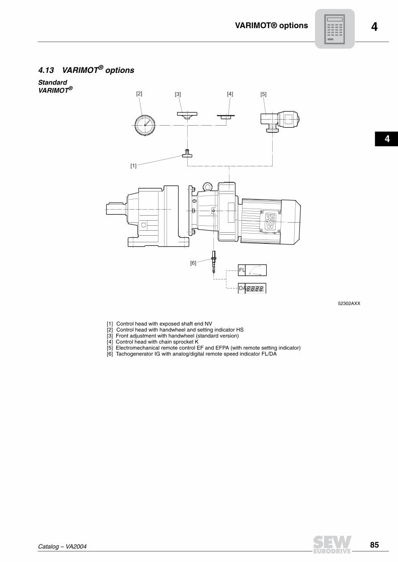
4.13 VARIMOT® optionsStandardVARIMOT®
52302AXX
[1] Control head with exposed shaft end NV[2] Control head with handwheel and setting indicator HS[3] Front adjustment with handwheel (standard version)[4] Control head with chain sprocket K[5] Electromechanical remote control EF and EFPA (with remote setting indicator)[6] Tachogenerator IG with analog/digital remote speed indicator FL/DA
[2] [3] [4] [5]
[1]
[6]
DA
FL

4 VARIMOT® options
86 Catalog – VA2004
Explosion-proof VARIMOT®
52019AXX
[1] Control head with exposed shaft end NV[2] Control head with handwheel and setting indicator HS[3] Front adjustment with handwheel (standard version)[4] Display scale[5] Voltage encoder IGEX
[2] [3]
[1]
[4][5]

4VARIMOT® options
Catalog – VA2004 87
1
2
3
4
Adjustment with chain sprocket K, with exposed shaft end NV or with handwheel with setting indicator HS
52304AXX
CCW direction of rotation on the adjustment spindle means an increase in speed. Thehandwheel with installed setting indicator HS only functions when the adjustmentspindle is horizontal.
[1] Handwheel with setting indicator HS[2] Chain sprocket K[3] Exposed shaft end NV
[1] [2]
[3]
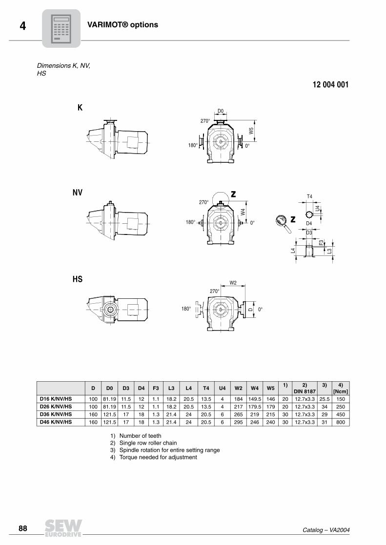
4 VARIMOT® options
88 Catalog – VA2004
Dimensions K, NV, HS
1) Number of teeth2) Single row roller chain3) Spindle rotation for entire setting range4) Torque needed for adjustment
D D0 D3 D4 F3 L3 L4 T4 U4 W2 W4 W51) 2)
DIN 81873) 4)
[Ncm]D16 K/NV/HS 100 81.19 11.5 12 1.1 18.2 20.5 13.5 4 184 149.5 146 20 12.7x3.3 25.5 150
D26 K/NV/HS 100 81.19 11.5 12 1.1 18.2 20.5 13.5 4 217 179.5 179 20 12.7x3.3 34 250
D36 K/NV/HS 160 121.5 17 18 1.3 21.4 24 20.5 6 265 219 215 30 12.7x3.3 29 450
D46 K/NV/HS 160 121.5 17 18 1.3 21.4 24 20.5 6 295 246 240 30 12.7x3.3 31 800

4VARIMOT® options
Catalog – VA2004 89
1
2
3
4
Electromechanical remote speed control EF/EFPA
53862AXX
Electromechanical remote speed control consists of a servo motor which, in the EFPAtype, is supplemented by an indicator unit. This indicator unit can be installed in a controlcabinet. Speed changes resulting from load fluctuations are not shown on the display.The electromechanical remote speed control EF/EFPA is designed for maximal40 % cdf and a starting frequency of < 20 cycles per hour. The minimum and maximumspeeds are determined by setting the two limit switches. The control unit can beswiveled to the positions shown (270° = normal position).The setting indicator is located at either 0° or 180° when the control head is in its normalposition. Specify the position of the control unit and, if required, the setting indicator andthe voltage of the variable motor in your order.
Electromechanical remote speed adjustments are not suitable for automaticcontrol but only for occasional adjustment.
Technical data
Variable motor
VARIMOT® type
Adjustment device
TypePm
[W]
U
[VAC]
f
[Hz]
I
[AAC]
na
[1/min]Enclosure Part number
D16...D46 EF/EFPADM90-60K + E13
with potentiometer
75 230/400 50 0.76/0.44 69 IP55 150 283 2

4 VARIMOT® options
90 Catalog – VA2004
Dimensions EF/EFPA
1) Adjustment time in seconds
Encoder IG, remote speed indicators FL and DA
52305AXX
H2 1)D16 EF/EFPA 202 22
D26 EF/EFPA 232 29
D36 EF/EFPA 268 25
D46 EF/EFPA 293 27
[1] Display DA[2] Remote speed indicator FL[3] Voltage encoder IG (3)
100
0
20
4060
%
80
[1]
[3][4]
[2]
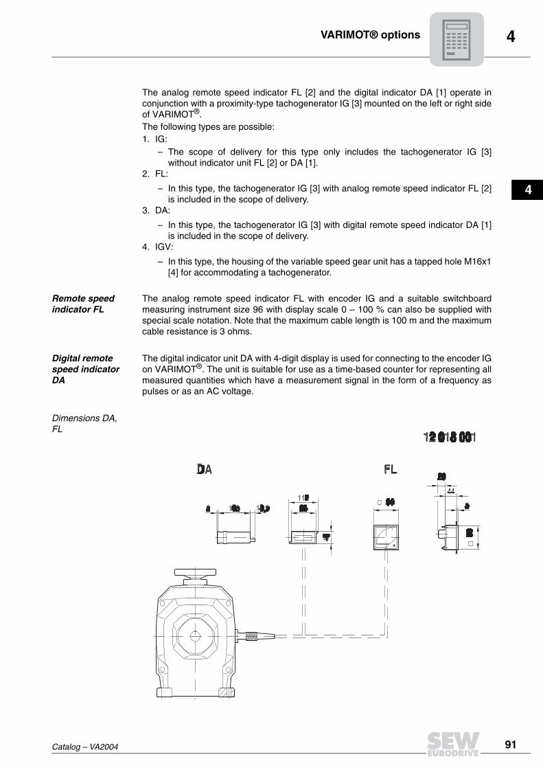
4VARIMOT® options
Catalog – VA2004 91
1
2
3
4
The analog remote speed indicator FL [2] and the digital indicator DA [1] operate inconjunction with a proximity-type tachogenerator IG [3] mounted on the left or right sideof VARIMOT®.The following types are possible:1. IG:
– The scope of delivery for this type only includes the tachogenerator IG [3]without indicator unit FL [2] or DA [1].
2. FL:
– In this type, the tachogenerator IG [3] with analog remote speed indicator FL [2]is included in the scope of delivery.
3. DA:
– In this type, the tachogenerator IG [3] with digital remote speed indicator DA [1]is included in the scope of delivery.
4. IGV:
– In this type, the housing of the variable speed gear unit has a tapped hole M16x1[4] for accommodating a tachogenerator.
Remote speed indicator FL
The analog remote speed indicator FL with encoder IG and a suitable switchboardmeasuring instrument size 96 with display scale 0 – 100 % can also be supplied withspecial scale notation. Note that the maximum cable length is 100 m and the maximumcable resistance is 3 ohms.
Digital remote speed indicator DA
The digital indicator unit DA with 4-digit display is used for connecting to the encoder IGon VARIMOT®. The unit is suitable for use as a time-based counter for representing allmeasured quantities which have a measurement signal in the form of a frequency aspulses or as an AC voltage.
Dimensions DA, FL