variable speed drives - maxautomation.co.in · variable speed drives ... communication via fipio...
TRANSCRIPT

Variable speed drives
Altivar 61
07CatalogueOctober
For 3-phase motors from 0.75 to 800 kW

This international site allows you to access all the
Telemecanique products in just 2 clicks via
comprehensive range data-sheets, with direct
links to:
Complete library: technical documents, catalogs,
certifi cates, FAQs, brochures...
Selection guides from the e-catalog.
Product discovery sites and their Flash
animations.
You will also fi nd illustrated overviews, news to
which you can subscribe, a discussion forum, the
list of country contacts...
To live automation solutions every day!
b
b
b
FlexibilityInterchangeable
modular functions,
to better meet the
requirements for
extensions
Software and
accessories common to
multiple product families
CompactnessHigh functionality in a
minimum of space
Freedom
inimplementation
b
b
b
b
IngenuityAuto-adapts to its
environment, “plug &
play”
Application functions,
control, communication
and diagnostics
embedded in the
products
User-friendly
operation either directly
on the product or
remotely
OpennessCompliance with fi eld
bus, connection, and
software standards
Enabling
decentralised or remote
surveillance via the web
with Transparent Ready
products
b
b
b
b
b
SimplicityCost effective
“optimum” offers that
make selection easy for
most typical applications
Products that are
easy to understand for
users, electricians and
automation specialists
User-friendly intuitive
programming
b
b
b


1
Variable speed drives
Altivar 61 0
Selection guide . . . . . . . . . . . . . . . . . . . . . . . . . . . . . . . . . . . . . . . . . . . . . . .page 2
Presentation . . . . . . . . . . . . . . . . . . . . . . . . . . . . . . . . . . . . . . . . . . . . . . . . page 4
Altivar 61 variable speed drives
Characteristics . . . . . . . . . . . . . . . . . . . . . . . . . . . . . . . . . . . . . . . . . . . . page 10
Operation . . . . . . . . . . . . . . . . . . . . . . . . . . . . . . . . . . . . . . . . . . . . . . . . page 18
UL Type 1/IP 20 and UL Type 12/IP 54 variable speed drives . . . . . . . . page 20
Accessories for UL Type 1/IP 20 and UL Type 12/IP 54
variable speed drives . . . . . . . . . . . . . . . . . . . . . . . . . . . . . . . . . . . . . . . page 26
Pre-equipped IP 54 fl oor-standing enclosure kit . . . . . . . . . . . . . . . . . . . page 34
IP 23 or IP 54 fl oor-standing enclosure compact version . . . . . . . . . . . . page 44
UL Type 12/IP 54 drives with Vario . . . . . . . . . . . . . . . . . . . . . . . . . . . . . page 74
IP 54 fl oor-standing enclosure with separate air fl ows . . . . . . . . . . . . . . page 78
Options
Dialogue . . . . . . . . . . . . . . . . . . . . . . . . . . . . . . . . . . . . . . . . . . . . . . . . page 108
Encoder interface cards . . . . . . . . . . . . . . . . . . . . . . . . . . . . . . . . . . . . page 110
I/O extension cards . . . . . . . . . . . . . . . . . . . . . . . . . . . . . . . . . . . . . . . page 112
Multi-pump cards . . . . . . . . . . . . . . . . . . . . . . . . . . . . . . . . . . . . . . . . . page 114
“Controller Inside” programmable card . . . . . . . . . . . . . . . . . . . . . . . . . page 118
Communication buses and networks . . . . . . . . . . . . . . . . . . . . . . . . . . page 126
Resistance braking units . . . . . . . . . . . . . . . . . . . . . . . . . . . . . . . . . . . page 136
Braking resistors . . . . . . . . . . . . . . . . . . . . . . . . . . . . . . . . . . . . . . . . . page 138
Reduction of current harmonics
DC chokes . . . . . . . . . . . . . . . . . . . . . . . . . . . . . . . . . . . . . . . . . . . . . page 146
line chokes. . . . . . . . . . . . . . . . . . . . . . . . . . . . . . . . . . . . . . . . . . . . . page 150
passive fi lters . . . . . . . . . . . . . . . . . . . . . . . . . . . . . . . . . . . . . . . . . . . page 155
Additional EMC input fi lters . . . . . . . . . . . . . . . . . . . . . . . . . . . . . . . . . page 160
Output fi lters
motor chokes . . . . . . . . . . . . . . . . . . . . . . . . . . . . . . . . . . . . . . . . . . . page 165
sinus fi lters. . . . . . . . . . . . . . . . . . . . . . . . . . . . . . . . . . . . . . . . . . . . . page 168
Combinations of variable speed drives and options. . . . . . . . . . . . . . page 170
Dimensions . . . . . . . . . . . . . . . . . . . . . . . . . . . . . . . . . . . . . . . . . . . . . . page 180
Schemes . . . . . . . . . . . . . . . . . . . . . . . . . . . . . . . . . . . . . . . . . . . . . . . . . page 206
Motor starters . . . . . . . . . . . . . . . . . . . . . . . . . . . . . . . . . . . . . . . . . . . . . page 228
Mounting recommendations . . . . . . . . . . . . . . . . . . . . . . . . . . . . . . . . . page 240
Functions . . . . . . . . . . . . . . . . . . . . . . . . . . . . . . . . . . . . . . . . . . . . . . . . page 254
Function compatibility table . . . . . . . . . . . . . . . . . . . . . . . . . . . . . . . . . page 282
PowerSuite software workshop . . . . . . . . . . . . . . . . . . . . . . . . . . . . . . page 284
Communication via Modbus TCP network . . . . . . . . . . . . . . . . . . . . . . page 288
Communication via Fipio bus . . . . . . . . . . . . . . . . . . . . . . . . . . . . . . . . page 294
Communication via Modbus serial link . . . . . . . . . . . . . . . . . . . . . . . . page 298
Communication via Modbus Plus network . . . . . . . . . . . . . . . . . . . . . page 302
Communication via Uni-Telway bus . . . . . . . . . . . . . . . . . . . . . . . . . . . page 306
Communication gateways LUF P . . . . . . . . . . . . . . . . . . . . . . . . . . . . . page 308
Product reference index . . . . . . . . . . . . . . . . . . . . . . . . . . . . . . . . . . . . page 311
b
b
v
v
v
v
v
v
v
v
b
v
v
v
v
v
v
v
v
v
-
-
-
v
v
-
-
b
b
b
b
b
b
b
b
b
b
b
b
b
b
b
Contents 0

2
Selection guide 2
Type of machine Simple machines Pumps and fans(building (HVAC) (1)
Power range for 50…60 Hz (kW) line supply 0.18…2.2 0.18…15 0.75…75
Single-phase 100…120 V (kW) 0.18…0.75 – –
Single-phase 200…240 V (kW) 0.18…2.2 0.18…2.2 –
Three-phase 200…230 V (kW) 0.18…2.2 – –
Three-phase 200…240 V (kW) – 0.18…15 0.75…30
Three-phase 380…480 V (kW) – – 0.75…75
Three-phase 380…500 V (kW) – 0.37…15 –
Three-phase 525…600 V (kW) – 0.75…15 –
Three-phase 500…690 V (kW) – – –
Drive Output frequency 0.5…200 Hz 0.5…500 Hz 0.5…200 Hz
Type of control Asynchronous motor Sensorless fl ux vector control Sensorless fl ux vector control, voltage/frequency ratio (2 points), energy saving ratio
Synchronous motor – –
Transient overtorque 150…170% of the nominal motor torque
180% of the nominal motor torque for 2 seconds
110% of the nominal motor torque
FunctionsNumber of functions 26 50 50
Number of preset speeds 4 16 7
Numberof I/O
Analog inputs 1 3 2
Logic inputs 4 6 3
Analog outputs – 1 1
Logic outputs 1 – –
Relay outputs 1 2 2
Communication Integrated – Modbus and CANopen Modbus
Available as an option – Modbus TCP, DeviceNet, Fipio, PROFIBUS DP
LONWORKS, METASYS N2,APOGEE FLN, BACnet
Cards (available as an option) – – –
Standards and certifi cations IEC/EN 61800-5-1, IEC/EN 61800-3 (environments 1 and 2)
EN 55011: Group 1, class A and class B.e, UL, CSA, C-Tick, N998
EN 55011: Group 1, class A and class B with option card, e, UL, CSA, C-Tick, N998
EN 55011: Group 1, class A and class B with option card,e, UL, CSA, C-Tick, NOM 117
References ATV 11 ATV 31 ATV 21
Pages Please consult our “Soft starters and variable speed drives” catalogue
(1) Heating, Ventilation and Air Conditioning
Variable speed drivesfor asynchronous and synchronous motors

3
Pumps and fans(industrial)
Complex machines
0.37…800 0.37…630
– –
0.37…5.5 0.37…5.5
– –
0.75…90 0.37…75
0.75…630 0.75…500
– –
– –
2.2…800 1.5…630
0.5…500 Hz for the entire range0.5…1000 Hz up to 37 kW at 200…240 V a and 380…480 V a
1…500 Hz across the entire range1…1600 Hz up to 37 kW at 200…240 V a and 380…480 V a
Sensorless fl ux vector control, voltage/frequency ratio (2 or 5 points), energy saving ratio
Sensor/sensorless fl ux vector control, voltage/frequency ratio (2 or 5 points), ENA System
– Vector control with or without speed feedback
120...130% of the nominal motor torque for 60 seconds 220% of the nominal motor torque for 2 seconds170% for 60 seconds
> 100 > 150
8 16
2…4 2…4
6…20 6…20
1…3 1…3
0…8 0…8
2…4 2…4
Modbus and CANopen
Modbus TCP, Fipio, Modbus/Uni-Telway, Modbus Plus, EtherNet/IP, DeviceNet, PROFIBUS DP, INTERBUS, CC-Link, LONWORKS, METASYS N2, APOGEE FLN, BACnet
Modbus TCP, Fipio, Modbus/Uni-Telway, Modbus Plus, EtherNet/IP, DeviceNet, PROFIBUS DP, INTERBUS, CC-Link
I/O extension cards, "Controller Inside" programmable card,multi-pump cards
Interface cards for incremental, resolver or absolute encoders,I/O extension cards, "Controller Inside" programmable card
IEC/EN 61800-5-1, IEC/EN 61800-3 (environments 1 and 2, C1 to C3), EN 55011, IEC/EN 61000-4-2/4-3/4-4/4-5/4-6/4-11 e, UL, CSA, DNV, C-Tick, NOM 117, GOST
ATV 61 ATV 71
20 to 25 Please consult our “Altivar 71 variable speed drives” catalogue and our “Soft starters and variable speed drives” catalogue
22
4
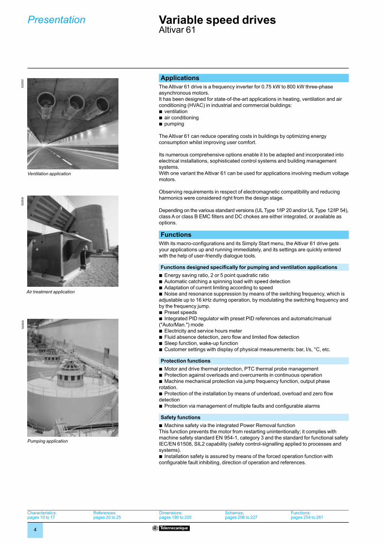
Applications
The Altivar 61 drive is a frequency inverter for 0.75 kW to 800 kW three-phase
asynchronous motors.
It has been designed for state-of-the-art applications in heating, ventilation and air
conditioning (HVAC) in industrial and commercial buildings:
b ventilation
b air conditioning
b pumping
The Altivar 61 can reduce operating costs in buildings by optimizing energy
consumption whilst improving user comfort.
Its numerous comprehensive options enable it to be adapted and incorporated into
electrical installations, sophisticated control systems and building management
systems.
With one variant the Altivar 61 can be used for applications involving medium voltage
motors.
Observing requirements in respect of electromagnetic compatibility and reducing
harmonics were considered right from the design stage.
Depending on the various standard versions (UL Type 1/IP 20 and/or UL Type 12/IP 54),
class A or class B EMC fi lters and DC chokes are either integrated, or available as
options.
Functions
With its macro-confi gurations and its Simply Start menu, the Altivar 61 drive gets
your applications up and running immediately, and its settings are quickly entered
with the help of user-friendly dialogue tools.
Functions designed specifi cally for pumping and ventilation applications
b Energy saving ratio, 2 or 5 point quadratic ratio
b Automatic catching a spinning load with speed detection
b Adaptation of current limiting according to speed
b Noise and resonance suppression by means of the switching frequency, which is
adjustable up to 16 kHz during operation, by modulating the switching frequency and
by the frequency jump.
b Preset speeds
b Integrated PID regulator with preset PID references and automatic/manual
("Auto/Man.") mode
b Electricity and service hours meter
b Fluid absence detection, zero fl ow and limited fl ow detection
b Sleep function, wake-up function
b Customer settings with display of physical measurements: bar, I/s, °C, etc.
Protection functions
b Motor and drive thermal protection, PTC thermal probe management
b Protection against overloads and overcurrents in continuous operation
b Machine mechanical protection via jump frequency function, output phase
rotation.
b Protection of the installation by means of underload, overload and zero fl ow
detection
b Protection via management of multiple faults and confi gurable alarms
Safety functions
b Machine safety via the integrated Power Removal function
This function prevents the motor from restarting unintentionally; it complies with
machine safety standard EN 954-1, category 3 and the standard for functional safety
IEC/EN 61508, SIL2 capability (safety control-signalling applied to processes and
systems).
b Installation safety is assured by means of the forced operation function with
confi gurable fault inhibiting, direction of operation and references.
Ventilation application
522835
Ventilation application
522835
522836
Air treatment application
522836
Air treatment application
Pumping application
522834
Pumping application
522834
Variable speed drivesAltivar 61
Presentation
Characteristics:pages 10 to 17
References:pages 20 to 25
Dimensions:pages 180 to 205
Schemes:pages 206 to 227
Functions:pages 254 to 281
Characteristics:pages 10 to 17
References:pages 20 to 25
Dimensions:pages 180 to 205
Schemes:pages 206 to 227
Functions:pages 254 to 281

5
A comprehensive offer The Altivar 61 range of variable speed drives can be used with motor power ratings
from 0.75 kW to 800 kW with three types of power supply:
b 200 240 V three-phase, 0.75 kW to 90 kW, UL Type 1/IP 20, (ATV 61HpppM3,
ATV 61HpppM3X)
b 380 480 V three-phase, 0.75 kW to 630 kW, UL Type 1/IP 20, (ATV 61HpppN4)
b 380 480 V three-phase, 0.75 kW to 90 kW, UL Type 12/IP 54, (ATV 61WpppN4,
ATV 61WpppN4C)
b 500 690 V three-phase, 1.5 kW to 800 kW, UL Type 1/IP 20, (ATV 61HpppY)
Altivar 61 UL Type 1/IP 20 drives can also be used with motor power ratings from
0.37 kW to 5.5 kW at single-phase 200…240 V, if the motor is derated.
The Altivar 61 drive integrates the Modbus and CANopen protocols as standard, as
well as numerous functions. These functions can be extended using communication
option cards, I/O extension cards, multi-pump cards and a "Controller Inside"
programmable card, see page 9.
External options such as braking resistors, resistance braking units and fi lters
complete the offer, see page 9.
The entire range conforms to international standards IEC/EN 61800-5-1,
IEC/EN 61800-2, IEC/EN 61800-3, is UL, CSA, DNV, C-Tick, NOM 117 and GOST
certifi ed and has been developed to meet the requirements of directives regarding
the protection of the environment (RoHS, WEEE, etc.) as well as those of European
Directives so as to meet e requirements.
Functional safety and ATEX applications (1)
The Altivar 61 variable speed drive features a safety function that is designed to
ensure a motor stop and prevent accidental restarts.
This Power Removal safety function means that the drive can be installed as part of
the safety system for an electrical/electronic/programmable electronic control
system in order to ensure the safety of a machine or industrial process.
This function meets the requirements of category 3 of the EN 954-1 machine safety
standard, SIL 2 of IEC/EN 61508 and the standard dealing with the functional safety
requirements of power drive products: IEC/EN 61800-5-2.
The Power Removal safety function also enables the Altivar 61 variable speed drive
to offer protection for motors that are installed in explosive atmospheres (ATEX), see
pages 208 and 209.
Electromagnetic compatibility (EMC)
Reducing harmonics and observing requirements in respect of electromagnetic
compatibility were considered right from the design stage.
The incorporation of EMC fi lters in ATV 61HpppM3 and ATV 61ppppN4 drives and
the observance of requirements in respect of EMC simplifi es installation and
provides an economical means of ensuring machines meet e marking
requirements.
ATV 61WpppN4C drives have integrated class B EMC fi lters, which make them
compliant with the requirements of EN 55011 (class B group 1) and IEC/EN 61800-3
(category C1) standards.
The ATV 61HpppM3X drives have been designed without an EMC fi lter. Filters are
available as an option and can be installed by the user to reduce emission levels,
see pages 160 to 163.
Flexibility and user-friendlinessAltivar 61 has numerous logic and analog inputs and outputs that can be confi gured
to adapt better to your applications.
It integrates the Modbus and CANopen protocols to enhance the performance of
your control systems. It also offers the main communication buses for the industry
and is easily integrated in building management systems (HVAC) via option cards.
It also has multi-pump cards which make it both fl exible and user-friendly when
managing a number of pumps.
(1) Please refer to the ATEX guide, which is available on our website at www.telemecanique.com.
537421
ATV 61HC31N4, ATV 61HD37M3X, ATV 61HU22N4
537421
ATV 61HC31N4, ATV 61HD37M3X, ATV 61HU22N4
ATV 61W075N4, ATV 61W075N4C
107495
ATV 61W075N4, ATV 61W075N4C
107495
Variable speed drivesAltivar 61
Presentation (continued)
Characteristics:pages 10 to 17
References:pages 20 to 25
Dimensions:pages 180 to 205
Schemes:pages 206 to 227
Functions:pages 254 to 281
Characteristics:pages 10 to 17
References:pages 20 to 25
Dimensions:pages 180 to 205
Schemes:pages 206 to 227
Functions:pages 254 to 281

6
Installation The Altivar 61 drive has been designed to optimize the size of enclosures (fl oor-
standing, wall-mounted, etc):
b The power section, with IP 54 degree of protection, can be easily mounted outside
the enclosure using kit VW3 A9 5pp for fl ush-mounting in a dust and damp proof
enclosure, see page 32. This type of mounting can be used to limit the temperature
rise in the enclosure and reduce its size.
b Ambient temperature in the enclosure:
v 50°C without derating, depending on the rating
v up to 60°C using control card fan kit VW3 A9 4pp depending on the rating, and
derating the output current if necessary, see page 27
b Mounting side-by-side, see pages 240, 243 and 252
The Altivar 61 drive can also be mounted on a wall in compliance with UL Type 1
conformity with kit VW3 A9 2pp, and IP 21 or IP 31 conformity with kit VW3 A9 1pp,
see pages 30 and 31.
Standard versions The Altivar 61 UL Type1/IP 20 range of variable speed drives offers various standard
versions.
Versions with IP 54 degree of protection for diffi cult environments
To meet the requirements of applications in diffi cult environments (dusty, humid, etc.),
drives can be supplied individually or inside a fl oor-standing enclosure:
b A drive version with UL Type 12/IP 54 degree of protection (see page 22):
v 380…480 V a, 0.75 kW to 90 kW (ATV 61WpppN4 and ATV 61WpppN4C)
b A drive version with UL Type 12/IP 54 degree of protection and featuring a Vario
switch disconnector (see pages 74 to 77):
v 380…480 V a, 0.75 to 90 kW (ATV 61E5pppN4)
b A drive version ready-assembled in an IP 54 fl oor-standing enclosure (see
pages 78 to 91):
v 380…415 V a, 90 kW to 630 kW (ATV 61EXS5pppN4)
v 500 V and 600…690 V a, 90 kW to 800 kW (ATV 61EXS5pppN and
ATV 61EXS5pppY)
The ATV 61EXS5pppN4, ATV 61EXS5pppN and ATV 61EXS5pppY products have
been designed for easy set-up in highly polluted environments and, in particular, to
ensure optimum enclosure ventilation by keeping the control and power air circuits
separate.
b A preassembled kit for creating an IP 54-certifi ed fl oor-standing enclosure (see
pages 34 to 43):
This straightforward and cost-effective solution, which is available by quoting a
single reference, provides you with all the mechanical components you need to
create an IP 54 fl oor-standing enclosure (VW3 A9 541…VW3 A9 551).
This product has been designed for compatibility with Altivar 61 UL Type 1/IP 20
drives, 110 kW to 630 kW at 380…480 V a (ATV 61HC11N4…HC63N4).
Compact fl oor-standing enclosure versions for industrial environments and
infrastructure contexts
The following product is available to facilitate set-up in industrial environments and
infrastructure contexts (tunnels, subways, smoke extraction and pumping, etc.):
b A drive version ready-assembled in an IP 23 or IP 54 compact fl oor-standing
enclosure (see pages 44 to 57):
v 380…415 V a, 90 kW to 630 kW (ATV 61EXCppppN4)
v 500 V a, 90 kW to 630 kW (ATV 71EXCppppN)
v 600…690 V a, 110 kW to 800 kW (ATV 61EXCppppY)
537172
ATV 61HU75N4, fl ush-mounted
537172
ATV 61HU75N4, fl ush-mounted
107580
ATV 61E5075N4
PF
107545
Kit VW3 A9 544
Variable speed drivesAltivar 61
Presentation (continued)
Characteristics:pages 10 to 17
References:pages 20 to 25
Dimensions:pages 180 to 205
Schemes:pages 206 to 227
Functions:pages 254 to 281
Characteristics:pages 10 to 17
References:pages 20 to 25
Dimensions:pages 180 to 205
Schemes:pages 206 to 227
Functions:pages 254 to 281
ATV 61EXC2pppN4
PF
107557

7
Mounting options The Altivar 61 drive can be mounted in a variety of ways for integration into
machines.
Mounting outside enclosure
The Altivar 61 can be mounted directly on a wall without having to be installed inside
an enclosure. UL Type 1 conformity can be achieved using kit VW3 A9 2pp, and
IP 21 or IP 31 with kit VW3 A9 1pp, (see pages 30 and 31).
Flush-mounting in a dust and damp proof enclosure
The Altivar 61 drive has been designed to optimize the size of enclosures (fl oor-
standing, wall-mounted, etc).
This type of fl ush-mounting can be used to reduce the size of enclosure required and
to limit the temperature rise inside the enclosure:
b The power section, with IP 54 degree of protection, can be easily mounted outside
the enclosure using kit VW3 A9 5pp for fl ush-mounting in a dust and damp proof
enclosure, see page 32.
b This type of mounting can lead to ambient temperatures of up to 60°C inside the
enclosure without derating. It may be necessary to use a control card fan kit
VW3 A9 4pp appropriate for the drive rating in order to avoid hot spots, see page 27
b This option permits mounting side-by-side, see pages 240 and 243.
Variable speed drivesAltivar 61
Presentation (continued)
Characteristics:pages 10 to 17
References:pages 20 to 25
Dimensions:pages 180 to 205
Schemes:pages 206 to 227
Functions:pages 254 to 281
Characteristics:pages 10 to 17
References:pages 20 to 25
Dimensions:pages 180 to 205
Schemes:pages 206 to 227
Functions:pages 254 to 281
DF
536808
ATV 61HU75N4, fl ush-mounted

8
Dialogue tools The Altivar 61 1 is supplied with a remote graphic display terminal 2:
b The navigation button can be used to access the drop-down menus quickly and
easily.
b The graphic screen displays 8 lines of 24 characters of plain text.
b The advanced functions on the display unit can be used to access the more
complex drive functions with ease.
b The display screens, menus and parameters can all be customized for the user or
the machine.
b Online help screens are available.
b Confi gurations can be stored and downloaded (four confi guration fi les can be
stored).
b The drive can be connected to several other drives via a multidrop link.
b It can be located remotely on an enclosure door with IP 54 or IP 65 degree of
protection (UL Type 1/IP20 drives) or built in (UL Type 12/IP 54 drives)
b It is supplied with six languages installed as standard (Chinese, English, French,
German, Italian and Spanish). Other languages can be loaded to the fl ash memory.
Up to 45 kW at 200…240 V and 75 kW at 380…480 V, the Altivar 61 can be
controlled using an integrated 7-segment display terminal, see page 24.
For all 500…690 V a ratings, the drive is supplied with an integrated 7-segment
display terminal and a remote graphic display terminal.
The PowerSuite software workshop 3 can be used for confi guration, adjustment,
debugging and maintenance of the Altivar 61 drive, like all the other Telemecanique
variable speed drives and starters . It can be used via a direct connection, Ethernet,
via a modem or a Bluetooth® wireless connection.
Quick programmingMacro-confi guration
The Altivar 61 offers quick and easy programming using macro-confi gurations
corresponding to different applications or uses: start-stop, pumping and ventilation,
general use, connection to communication networks, PID regulator.
Each of these confi gurations is still fully modifi able.
Simply Start menu
The Simply start menu can be used to ensure that the application is working
correctly, maximize motor performance and ensure motor protection.
The architecture, the hierarchical parameter structure and the direct access
functions all serve to make programming quick and easy, even for the more complex
functions.
Services The Altivar 61 has numerous built-in maintenance, monitoring and diagnostic
functions:
b Drive test functions with diagnostic screen on the remote graphic display terminal
b I/O maps
b Communication maps for the different ports
b Oscilloscope function that can be viewed using the PowerSuite software
workshop
b Management of the drive installed base via microprocessors with fl ash memory
b Remote use of these functions by connecting the drive to a modem via the
Modbus port
b Identifi cation of all the drive’s component parts as well as the software versions
b Fault logs that can display the values for up to 16 variables in the event of a fault
b Display terminal languages loaded in the fl ash memory
b A message of up to 5 lines of 24 characters can be stored in the drive.
1
2
3
1
2
3
534783
Simply Start menu
Pumps.Fans
50Hz IEC
2.2kW
400V
:
:
:
:
: 2 wire
+50.00HzTerm
1.1 SIMPLY START
Standard mot. Freq.
5.4A
Macro-configuration
Rated motor power
Rated motor volt.
<< >> QuickCode
RUN
2/3 wire control
534783
Simply Start menu
Pumps.Fans
50Hz IEC
2.2kW
400V
:
:
:
:
: 2 wire
+50.00HzTerm
1.1 SIMPLY START
Standard mot. Freq.
5.4A
Macro-configuration
Rated motor power
Rated motor volt.
<< >> QuickCode
RUN
2/3 wire control
+50.00HzTerm
FAULT HISTORY
External FLT
0.0A
Overcurrent
Overvoltage
Undervoltage
QuickHelp
SCF1
Short circuit
533523
Fault log
+50.00HzTerm
FAULT HISTORY
External FLT
0.0A
Overcurrent
Overvoltage
Undervoltage
QuickHelp
SCF1
Short circuit
533523
Fault log
+50.00HzTerm
MOTOR SHORT CIRCUIT
0.0A
Perform the diagnostic test.
Quick
SCF1
Check the connection cables
and the motor insulation.
522162
Troubleshooting screen
+50.00HzTerm
MOTOR SHORT CIRCUIT
0.0A
Perform the diagnostic test.
Quick
SCF1
Check the connection cables
and the motor insulation.
522162
Troubleshooting screen
Variable speed drivesAltivar 61
Presentation (continued)
Characteristics:pages 10 to 17
References:pages 20 to 25
Dimensions:pages 180 to 205
Schemes:pages 206 to 227
Functions:pages 254 to 281
Characteristics:pages 10 to 17
References:pages 20 to 25
Dimensions:pages 180 to 205
Schemes:pages 206 to 227
Functions:pages 254 to 281

9
Options
The Altivar 61 drive 1 can accommodate a maximum of two option cards
simultaneously (1):
b I/O extension cards 2, which can be confi gured to adapt better to your
applications, see pages 112 and 113
b Communication cards 2 dedicated to industry or to building management (HVAC),
see pages 126 to 135
b Multi-pump cards 2 which make it both fl exible and user-friendly when managing a
number of pumps, see pages 114 to 117
b "Controller Inside" programmable card 2. This is used to adapt the drive to specifi c
applications quickly and progressively, by decentralizing the control system functions
(programming in IEC 61131-3 compliant languages), see pages 118 to 125.
Various external options can be combined with the Altivar 61:
b Braking units and resistors, see pages 136 to 145
b Line chokes, DC chokes and passive fi lters (to reduce harmonic currents), see
pages 146 to 159
b Additional EMC input fi lters, see pages 160 to 163
b Motor chokes and sinus fi lters for long cable runs or to remove the need for
shielding, see pages 164 to 169
Note: Please refer to the compatibility summary tables to determine which options are available for individual drives, see pages 170 to 179.
Integration into control systems and building management
systems
The Altivar 61 has a combined Modbus or CANopen port for adjustment, monitoring
and confi guration. A second port is available for connecting a Magelis terminal for
machine dialogue.
The Altivar 61 can also be connected to other communication networks using the
communication option cards, see pages 126 to 135. All communication protocols for
use in industry (Modbus TCP, Fipio, Modbus, Modbus Plus, Ethernet/IP, Uni-Telway,
PROFIBUS DP, DeviceNet, INTERBUS and CC-Link) or in building management
(LonWorks, METASYS N2, APOGEE FLN, BACnet) are available.
The option of powering the control part separately enables communication to be
maintained (monitoring, diagnostics) even if there is no power supply to the power
part.
The "Controller Inside" programmable card transforms the drive into an automation
island:
b The card has its own I/O; it can also manage those of the drive and an I/O
extension card.
b It contains onboard application programs developed in IEC 61131-3 languages,
which reduce the control system response time.
b Its CANopen master port enables control of other drives and dialogue with I/O
modules and sensors.
The two multi-pump cards can be used to adapt the drive to pump applications.
The VW3 A3 502 multi-pump card ensures compatibility of pump applications
developed for an Altivar 38 drive with an Altivar 61.
The VW3 A3 503 multi-pump card is used to develop all multi-pump applications.
Multi-pump cards have their own I/O. They can manage the drive I/O as well as
those for the I/O extension cards. They can also use drive parameters such as
speed, current, torque, etc.
(1) The Altivar 61 cannot support more than one option card with the same reference. Consult the summary tables of possible drive, option and accessory combinations, see pages 170 to 179.
1
2 2
1
2 2
Variable speed drivesAltivar 61
XCCencoder
Example of a drive equipped with a communication card and the "Controller Inside" programmable card
Premium ATV 61
MagelisXBT
STB I/OATV 31
OTB I/O Sensor
ModbusEthernet
CANopen master
Presentation (continued)
Characteristics:pages 10 to 17
References:pages 20 to 25
Dimensions:pages 180 to 205
Schemes:pages 206 to 227
Functions:pages 254 to 281
Characteristics:pages 10 to 17
References:pages 20 to 25
Dimensions:pages 180 to 205
Schemes:pages 206 to 227
Functions:pages 254 to 281

10
Environmental characteristicsConforming to standards Altivar 61 drives have been developed to conform to the strictest international standards
and the recommendations relating to electrical industrial control devices (IEC, EN), in particular: low voltage, IEC/EN 61800-5-1, IEC/EN 61800-3 (conducted and radiated EMC immunity and emissions).
EMC immunity IEC/EN 61800-3, environments 1 and 2IEC/EN 61000-4-2 level 3IEC/EN 61000-4-3 level 3IEC/EN 61000-4-4 level 4IEC/EN 61000-4-5 level 3IEC/EN 61000-4-6 level 3IEC/EN 61000-4-11 (1)
Conducted and radiated EMC emissions for drives
IEC/EN 61800-3, environments 1 and 2, categories C1, C2, C3
ATV 61H075M3…HU22M3ATV 61H075N4…HU40N4
EN 55011 class A group 1, IEC/EN 61800-3 category C2With additional EMC fi lter (2):b EN 55011 class B group 1, IEC/EN 61800-3 category C1
ATV 61HU30M3…HU75M3ATV 61HU55N4…HC63N4
EN 55011 class A group 2, IEC/EN 61800-3 category C3With additional EMC fi lter (2):b EN 55011 class A group 1, IEC/EN 61800-3 category C2b EN 55011 class B group 1, IEC/EN 61800-3 category C1
ATV 61HpppM3X With additional EMC fi lter (2):b EN 55011 class A group 1, IEC/EN 61800-3 category C2b EN 55011 class B group 1, IEC/EN 61800-3 category C1
ATV 61HpppY EN 55011 class A group 2, IEC/EN 61800-3 category C3
ATV 61W075N4…WD90N4 EN 55011 class A group 1, IEC/EN 61800-3 category C2
ATV 61W075N4C…WD90N4C EN 55011 class B group 1, IEC/EN 61800-3 category C1
e The drives have e marking in accordance with the European directives on low voltage (2006/95/EC) and EMC (89/336/EEC).
Product certifi cation ATV 61HpppM3ATV 61HD11M3X…HD45M3XATV 61HD55M3XD, HD75M3XDATV 61H075N4…HD75N4ATV 61HD90N4D…HC50N4DATV 61HpppY
UL, CSA, C-Tick, NOM 117 and GOSTDNV with the dedicated kit, see pages 28 and 29
ATV 61WpppN4, WpppN4C UL, CSA, C-Tick, NOM 117 and GOST
Maximum ambient pollutionDefi nition of insulation
ATV 61HpppM3ATV 61HD11M3X, HD15M3X ATV 61H075N4…HD18N4 ATV 61W075N4…WD15N4 ATV 61W075N4C…WD15N4C
Degree 2 conforming to IEC/EN 61800-5-1
ATV 61HD18M3X…HD90M3XATV 61HD22N4…HC63N4ATV 61HpppYATV 61WD18N4…WD90N4ATV 61WD18N4C…WD90N4C
Degree 3 conforming to IEC/EN 61800-5-1Degree 3 in accordance with UL marking conforming to UL840
Degree of protection IEC/EN 61800-5-1, IEC/EN 60529
ATV 61HpppM3ATV 61HD11M3X…HD45M3XATV 61H075N4…HD75N4ATV 61HU30Y…HD90Y
IP 21 and IP 41 on upper partIP 20 without blanking plate on upper part of coverIP 54 on lower part (heatsink)IP 21 with accessory VW3 A9 1pp, UL Type 1 with accessory VW3 A9 2pp,see pages 30 and 31
ATV 61HD55M3X…HD90M3XATV 61HD90N4…HC31N4ATV 61HC11Y…HC40Y
IP 00, IP 41 on the upper part and IP 30 on the front panel and side partsIP 54 on lower part (heatsink)IP 31 with accessory VW3 A9 1pp, UL Type 1 with accessory VW3 A9 2pp,see pages 30 and 31
ATV 61HC40N4…HC63N4ATV 61HC50Y…HC80Y
IP 00, IP 41 on the upper part and IP 30 on the front panel and side partsIP 31 with accessory VW3 A9 1pp, see page 31
ATV 61W075N4…WD90N4ATV 61W075N4C…WD90N4C
UL Type 12/IP 54
Vibration resistance ATV 61HpppM3ATV 61HD11M3X…HD45M3XATV 61HU075N4…HD75N4ATV 61HU30Y…HD90YATV 61W075N4…WD75N4ATV 61W075N4C…WD75N4C
1.5 mm peak to peak from 3…13 Hz, 1 gn from 13…200 Hz, conforming to IEC/EN 60068-2-6
ATV 61HD55M3X…HD90M3XATV 61HD90N4…HC63N4ATV 61HC11Y…HC80YATV 61WD90N4ATV 61WD90N4C
1.5 mm peak to peak from 3…10 Hz, 0.6 gn from 10…200 Hz, conforming to IEC/EN 60068-2-6
Note: Unless specifi cally indicated on pages 10 to 17, the characteristics of drives with a "337", "S337", "387" or "A24" variant are identical, at equivalent ratings, to the standard drive.
(1) Drive behaviour according to the drive confi gurations, see pages 272, 273, 279 and 280.(2) See table on page 162 to check permitted cable lengths.
Variable speed drives Altivar 61
Presentation:pages 4 to 9
References:pages 20 to 25
Dimensions:pages 180 to 205
Schemes:pages 206 to 227
Functionspages 254 to 281
Presentation:pages 4 to 9
References:pages 20 to 25
Dimensions:pages 180 to 205
Schemes:pages 206 to 227
Functionspages 254 to 281
Characteristics

11
Environmental characteristics (continued)
Shock resistance ATV 61HpppM3ATV 61HD11M3X…HD45M3XATV 61H075N4…HD75N4ATV 61HU30Y…HD90YATV 61W075N4…WD75N4ATV 61W075N4C…WD75N4C
15 gn for 11 ms conforming to IEC/EN 60068-2-27
ATV 61HD55M3X…HD90M3XATV 61HD90N4…HC16N4ATV 61HC11Y…HC20YATV 61WD90N4ATV 61WD90N4C
7 gn for 11 ms conforming to IEC/EN 60068-2-27
ATV 61HC22N4…HC63N4ATV 61HC25Y…HC80Y
4 gn for 11 ms conforming to IEC/EN 60068-2-27
EnvironmentalconditionsUse
ATV 61HpppM3,ATV 61HD11M3X…HD45M3X, ATV 61H075N4…HD75N4, ATV 61WpppN4,ATV 61WpppN4C
IEC 60721-3-3 classes 3C1 and 3S2
ATV 61HpppM3S337,ATV 61HD11M3X337…HD45M3X337, ATV 61HD55M3X…HD90M3X, ATV 61H075N4S337…HD75N4S337, ATV 61HD90N4…HC63N4, ATV 61HpppY, ATV 61WpppN4A24
IEC 60721-3-3 class 3C2
Relative humidity 5…95% without condensation or dripping water conforming to IEC 60068-2-3
Ambient air temperaturearound the device
Operation °C For ATV 61Hppppp drives: - 10…+ 50 without derating, depending on the rating.Up to + 60°C with derating (and with control card fan kit VW3 A9 4pp depending on the rating). For ATV 61Wppppp drives: - 10…+ 40 without derating.See the derating curves on pages 241 to 253.
Storage °C - 25…+ 70
Maximum operating altitude
ATV 61HpppM3, ATV 61HpppM3X,ATV 61HpppN4,ATV 61WpppN4,ATV 61WpppN4C
m 1000 without derating1000…3000 derating the current by 1% per additional 100 m. Limited to 2000 m for the Corner Grounded distribution network
ATV 61HpppY m 1000 without derating1000…2260 derating the current by 1% per additional 100 m.
Operating position Maximum permanent angle in relation to the normal vertical mounting position
10° 10°10° 10°
Variable speed drivesAltivar 61
Characteristics (continued)
Presentation:pages 4 to 9
References:pages 20 to 25
Dimensions:pages 180 to 205
Schemes:pages 206 to 227
Functionspages 254 to 281
Presentation:pages 4 to 9
References:pages 20 to 25
Dimensions:pages 180 to 205
Schemes:pages 206 to 227
Functionspages 254 to 281

12
Drive characteristicsOutput frequency range
ATV 61HpppM3ATV 61HD11M3X…HD37M3XATV 61H075N4…HD37N4
Hz 0.5…1000
ATV 61HD45M3X…HD90M3X ATV 61HD45N4…HC63N4ATV 61HpppYATV 61WpppN4ATV 61WpppN4C
Hz 0.5…500
Confi gurable switching frequency
ATV 61HpppM3,ATV 61HD11M3X…HD45M3X,ATV 61H075N4…HD75N4
kHz Nominal switching frequency: 12 kHz without derating in continuous operation. Adjustable during operation from 1…16 kHzAbove 12 kHz, see the derating curves on pages 240 and 241
ATV 61HD55M3X kHz Nominal switching frequency: 2.5 kHz without derating in continuous operation.Adjustable during operation from 2.5…12 kHz Above 2.5 kHz, see the derating curves on pages 243 and 244
ATV 61HD75M3X, HD90M3X kHz Nominal switching frequency: 2.5 kHz without derating in continuous operation. Adjustable during operation from 2.5…8 kHzAbove 2.5 kHz, see the derating curves on pages 243 and 244
ATV 61HD90N4 kHz Nominal switching frequency: 4 kHz without derating in continuous operation. Adjustable during operation from 2…8 kHzAbove 4 kHz, see the derating curves on pages 243 and 244
ATV 61HC11N4…HC63N4 kHz Nominal switching frequency: 2.5 kHz without derating in continuous operation. Adjustable during operation from 2…8 kHzAbove 2.5 kHz, see the derating curves on pages 243 to 246.
ATV 61HU30Y…HD30Y kHz Nominal switching frequency: 4 kHz without derating in continuous operation. Adjustable during operation from 2.5…6 kHzAbove 4 kHz, see the derating curves on pages 240 and 242
ATV 61HD37Y…HC80Y kHz Nominal switching frequency: 2.5 kHz without derating in continuous operation. Adjustable during operation from 2.5…4.9 kHzAbove 2.5 kHz, see the derating curves on pages 240, 242, 243, 247 and 248
ATV 61W075N4…WD15N4ATV 61W075N4C…WD15N4C
kHz Nominal switching frequency: 8 kHz without derating in continuous operation. Adjustable during operation from 2…16 kHzAbove 8 kHz, see the derating curves on pages 252 and 253
ATV 61WD18N4…WD90N4ATV 61WD18N4C…WD90N4C
kHz Nominal switching frequency: 4 kHz without derating in continuous operation. Adjustable during operation from 2…16 kHzAbove 8 kHz, see the derating curves on pages 252 and 253
Speed range 1…100 in open-loop mode, without speed feedback
Speed accuracy For a torque variation of 0.2 Tn to Tn ± 10% of nominal slip, without speed feedback
Torque accuracy ± 15% in open-loop mode, without speed feedback
Transient overtorque 130% of the nominal motor torque (typical value at ± 10%) for 60 s
Braking torque 30% of the rated motor torque without braking resistor (typical value)Up to 125% with braking resistor installed as an option, see page 140
Maximum transient current
ATV 61HpppM3ATV 61HpppM3XATV 61HpppN4
130% of the nominal drive current for 60 s (typical value)
ATV 61HpppYATV 61WpppN4ATV 61WpppN4C
120% of the nominal drive current for 60 s (typical value)
Motor control profi le Asynchronous motor Sensorless Flux Vector Control (FVC) (voltage vector). Voltage/frequency ratio (2 or 5 points). Energy saving ratio
Synchronous motor Vector control without speed feedback
Frequency loop PI regulator with adjustable structure for an adapted speed response (accuracy, speed)
Slip compensation Automatic whatever the load. Can be suppressed or adjustedNot available in voltage/frequency ratio
Variable speed drivesAltivar 61
Characteristics (continued)
Presentation:pages 4 to 9
References:pages 20 to 25
Dimensions:pages 180 to 205
Schemes:pages 206 to 227
Functionspages 254 to 281
Presentation:pages 4 to 9
References:pages 20 to 25
Dimensions:pages 180 to 205
Schemes:pages 206 to 227
Functionspages 254 to 281

13
Electrical power characteristicsPower supply Voltage V 200 - 15%...240 + 10% single-phase for ATV 61H075M3...HU75M3
200 - 15%...240 + 10% three-phase for ATV 61HpppM3 and ATV 61HpppM3X380 - 15%...480 + 10% three-phase for ATV 61ppppN4 and ATV 61WpppN4C500 - 15%...690 + 10% three-phase for ATV 61HpppY
Frequency Hz 50 - 5%...60 + 5%
Signalling 1 red LED: LED lit indicates the presence of drive voltage
Output voltage Maximum three-phase voltage equal to line supply voltage
Drive noise level Conforming to directive 86-188/EEC
ATV 61H075M3, HU15M3ATV 61H075N4…HU22N4ATV 61W075N4…WU30N4ATV 61W075N4C…WU30N4C
dBA 43
ATV 61HU22M3…HU40M3ATV 61HU30N4, HU40N4ATV 61WU40N4, WU55N4ATV 61WU40N4C, WU55N4C
dBA 54.5
ATV 61HU55M3ATV 61HU55N4, HU75N4ATV 61WU75N4, WD11N4ATV 61WU75N4C, WD11N4C
dBA 55.6
ATV 61HU75M3ATV 61HD11N4ATV 61WD15N4ATV 61WD15N4C
dBA 57.4
ATV 61HD11M3X, HD15M3XATV 61HD15N4, HD18N4ATV 61WD18N4, WD22N4ATV 61WD18N4C, WD22N4C
dBA 60.2
ATV 61HD18M3X, HD22M3XATV 61HD22N4ATV 61HU30Y…HD30YATV 61WD30N4ATV 61WD30N4C
dBA 59.9
ATV 61HD30M3X…HD45M3X, ATV 61HD30N4, HD37N4ATV 61WD37N4, WD45N4ATV 61WD37N4C, WD45N4C
dBA 64
ATV 61HD45N4…HD75N4ATV 61HD37Y…HD90YATV 61WD55N4…WD90N4ATV 61WD55N4C…WD90N4C
dBA 63.7
ATV 61HD55M3X, HD75M3XATV 61HD90N4, HC11N4
dBA 60.5
ATV 61HD90M3XATV 61HC13N4
dBA 69.5
ATV 61HC16N4, HC22N4 dBA 66
ATV 61HC11Y…HC20Y dBA 77
ATV 61HC25N4, HC31N4 dBA 68
ATV 61HC25Y…HC40Y dBA 77
ATV 61HC40N4, HC50N4 dBA 70
ATV 61HC63N4 dBA 71
ATV 61HC50Y…HC80Y dBA 77
Electrical isolation Between power and control (inputs, outputs, power supplies)
Variable speed drives Altivar 61
Characteristics (continued)
Presentation:pages 4 to 9
References:pages 20 to 25
Dimensions:pages 180 to 205
Schemes:pages 206 to 227
Functionspages 254 to 281
Presentation:pages 4 to 9
References:pages 20 to 25
Dimensions:pages 180 to 205
Schemes:pages 206 to 227
Functionspages 254 to 281

14
Connection cable characteristicsCable type for Mounting in an enclosure Single-strand IEC cable, ambient temperature 45°C,
copper 90°C XLPE/EPR or copper 70°C PVC
Mounting in an enclosure with an IP 21 or IP 31 kit
3-strand IEC cable, ambient temperature 40°C, copper 70°C PVC
Mounting in an enclosure with a UL Type 1 kit 3-strand UL 508 cable except for choke (2-strand UL 508 cable),ambient temperature 40°C, copper 75°C PVC
Connection characteristics (terminals for the power supply, the motor, the DC bus and the braking resistor)
Drive terminals L1/R, L2/S, L3/T, U/T1, V/T2, W/T3 PC/-, PO (1), PA/+ PA, PB
Maximum wire size and tightening torque
ATV 61H075M3…HU40M3ATV 61H075N4…HU40N4
4 mm2, AWG 101.4 Nm, 12.3 lb.in
ATV 61HU55M3ATV 61HU55N4, HU75N4
6 mm2, AWG 83 Nm, 26.5 lb.in
ATV 61HU75M3ATV 61HD11N4
16 mm2, AWG 43 Nm, 26.5 lb.in
ATV 61HD11M3X, HD15M3XATV 61HD15N4, HD18N4
35 mm2, AWG 25,4 Nm, 47.7 lb.in
ATV 61HD18M3X, HD22M3XATV 61HD22N4…HD37N4ATV 61HU30Y…HD30Y
50 mm2, AWG 1/012 Nm, 102.2 lb.in
ATV 61HD30M3X…HD45M3XATV 61HD45N4…HD75N4ATV 61HD37Y…HD90Y
150 mm2, 300 MCM41 Nm, 360 lb.in
ATV 61HD55M3X, HD75M3X 2 x 100 mm2, 2 x 250 MCMM10, 24 Nm, 212 lb.in
2 x 100 mm2, 2 x 250 MCMM12, 41 Nm, 360 lb.in
60 mm2, 250 MCMM8, 12 Nm, 106 lb.in
ATV 61HD90M3X 2 x 100 mm2, 2 x 250 MCMM10, 24 Nm, 212 lb.in
2 x 150 mm2, 2 x 250 MCMM12, 41 Nm, 360 lb.in
60 mm2, 250 MCMM8, 12 Nm, 106 lb.in
ATV 61HD90N4, HC11N4 2 x 100 mm2, 2 x 250 MCMM10, 24 Nm, 212 lb.in
2 x 100 mm2, 2 x 250 MCMM12, 41 Nm, 360 lb.in
60 mm2, 250 MCMM8, 12 Nm, 106 lb.in
ATV 61HC13N4 2 x 100 mm2, 2 x 250 MCMM10, 24 Nm, 212 lb.in
2 x 150 mm2, 2 x 250 MCMM12, 41 Nm, 360 lb.in
60 mm2, 250 MCMM8, 12 Nm, 106 lb.in
ATV 61HC16N4ATV 61HC11Y…HC20Y
2 x 120 mm2, 2 x 250 MCMM10, 24 Nm, 212 lb.in
2 x 120 mm2, 2 x 250 MCMM10, 24 Nm, 212 lb.in
120 mm2, 250 MCMM10, 24 Nm, 212 lb.in
ATV 61HC22N4 2 x 150 mm2, 2 x 350 MCMM12, 41 Nm, 360 lb.in
2 x 150 mm2, 2 x 350 MCMM12, 41 Nm, 360 lb.in
120 mm2, 250 MCMM10, 24 Nm, 212 lb.in
ATV 61HC25N4, HC31N4ATV 61HC25Y…HC40Y
4 x 185 mm2, 3 x 350 MCMM12, 41 Nm, 360 lb.in
4 x 185 mm2, 3 x 350 MCMM12, 41 Nm, 360 lb.in
–
ATV 61HC40N4 4 x 185 mm2, 4 x 500 MCMM12, 41 Nm, 360 lb.in
8 x 185 mm2, 4 x 500 MCMM12, 41 Nm, 360 lb.in
–
R/L1.1, S/L2.1, T/L3.1, R/L1.2, S/L2.2, T/L3.2
ATV 61HC50N4 2 x 2 x 185 mm2, 2 x 2 x 500 MCMM12, 41 Nm, 360 lb.in
8 x 185 mm2, 4 x 500 MCMM12, 41 Nm, 360 lb.in
–
U/T1, V/T2, W/T3
4 x 185 mm2, 4 x 500 MCMM12, 41 Nm, 360 lb.in
R/L1.1, S/L2.1, T/L3.1, R/L1.2, S/L2.2, T/L3.2
ATV 61HC63N4ATV 61HC50Y…HC80Y
2 x 4 x 185 mm2, 2 x 3 x 500 MCMM12, 41 Nm, 360 lb.in
8 x 185 mm2, 5 x 500 MCMM12, 41 Nm, 360 lb.in
–
U/T1, V/T2, W/T3
6 x 185 mm2, 5 x 500 MCMM12, 41 Nm, 360 lb.in
ATV 61W075N4…WU55N4ATV 61W075N4C…WU55N4C
4 mm2, AWG 81.4 Nm, 12.3 lb.in
ATV 61WU75N4, WD11N4ATV 61WU75N4C, WD11N4C
6 mm2, AWG 63 Nm, 26.5 lb.in
ATV 61WD15N4ATV 61WD15N4C
16 mm2, AWG 43 Nm, 26.5 lb.in
ATV 61WD18N4, WD22N4ATV 61WD18N4C, WD22N4C
35 mm2, AWG 25.4 Nm, 47.7 lb.in
ATV 61WD30N4ATV 61WD30N4C
50 mm2, AWG 1/024 Nm, 212 lb.in
ATV 61WD37N4, WD45N4ATV 61WD37N4C, WD45N4C
50 mm2, AWG 1/024 Nm, 212 lb.in
ATV 61WD55N4ATV 61WD55N4C
150 mm2, 300 MCM41 Nm, 360 lb.in
ATV 61WD75N4ATV 61WD75N4C
150 mm2, 300 MCM41 Nm, 360 lb.in
ATV 61WD90N4ATV 61WD90N4C
150 mm2, 300 MCM41 Nm, 360 lb.in
(1) There is no PO terminal on ATV 61HC11Y…HC80Y drives.
Variable speed drives Altivar 61
Characteristics (continued)
Presentation:pages 4 to 9
References:pages 20 to 25
Dimensions:pages 180 to 205
Schemes:pages 206 to 227
Functionspages 254 to 281
Presentation:pages 4 to 9
References:pages 20 to 25
Dimensions:pages 180 to 205
Schemes:pages 206 to 227
Functionspages 254 to 281

15
Electrical control characteristicsAvailable internal supplies Short-circuit and overload protection:
b 1 x 10.5 V c ± 5% supply for the reference potentiometer (1 to 10 k ),maximum current 10 mA
b 1 x 24 V c supply (min. 21 V, max. 27 V), maximum current 200 mA
External + 24 V power supply (1)(not supplied)
24 V c (min. 19 V, max. 30 V) Power 30 W
Analog inputs AI1-/AI1+ 1 bipolar differential analog input ± 10 V c (maximum safe voltage 24 V)Max. sampling time: 2 ms ± 0.5 msResolution: 11 bits + 1 sign bitAccuracy: ± 0.6% for a temperature variation of 60°CLinearity: ± 0.15% of the maximum value
AI2 1 software-confi gurable voltage or current analog input:b Voltage analog input 0...10 V c , impedance 30 k (max. safe voltage 24 V)b Current analog input X-Y mA by programming X and Y from 0 to 20 mA, with
impedance 242 Max. sampling time: 2 ms ± 0.5 msResolution: 11 bitsAccuracy: ± 0.6% for a temperature variation of 60°CLinearity: ± 0.15% of the maximum value
Other inputs See option cards
Analog outputs AO1 1 software-confi gurable voltage or current analog output or logic output:b Voltage analog output 0...10 V c, min. load impedance 470 b Current analog output X-Y mA by programming X and Y from 0 to 20 mA, max. load
impedance 500 Max. sampling time: 2 ms ± 0.5 msResolution: 10 bitsAccuracy: ± 1% for a temperature variation of 60°CLinearity: ± 0.2%b Logic output: 10 V, 20 mA max.
Other outputs See option cards
Confi gurable relay outputs R1A, R1B, R1C 1 x relay logic output, 1 x "N/C" contact and 1 x "N/O" contact with common pointMinimum switching capacity: 3 mA for 24 V cMaximum switching capacity:b On resistive load (cos = 1): 5 A for 250 V a or 30 V cb On inductive load (cos = 0.4 and L/R = 7 ms): 2 A for 250 V a or 30 V cMax. response time: 7 ms ± 0.5 msElectrical service life: 100,000 operations
R2A, R2B 1 x relay logic output, 1 x "N/O" contactMinimum switching capacity: 3 mA for 24 V cMaximum switching capacity:b On resistive load (cos = 1): 5 A for 250 V a or 30 V cb On inductive load (cos = 0.4 and L/R = 7 ms): 2 A for 250 V a or 30 V cMax. response time: 7 ms ± 0.5 msElectrical service life: 100,000 operations
Other outputs See option cards
Logic inputs LI LI1...LI5 5 programmable logic inputs 24 V c, compatible with level 1 PLC, IEC/EN 61131-2 standardImpedance: 3.5 kMaximum voltage: 30 VMax. sampling time: 2 ms ± 0.5 msMultiple assignment makes it possible to confi gure several functions on one input (example: LI1 assigned to forward and preset speed 2, LI3 assigned to reverse and preset speed 3)
LI6 1 logic input, switch-confi gurable as a logic input or as an input for PTC probesLogic input, characteristics identical to inputs LI1...LI5Input for a maximum of 6 PTC probes mounted in series:b Nominal value < 1.5 kb Trip resistance 3 k , reset value 1.8 kb Short-circuit protection < 50 This logic input must never be used to protect an ATEX motor in applications in explosive atmospheres (2).
Positive logic (Source) State 0 if y 5 V or logic input not wired, state 1 if u 11 V
Negative logic (Sink) State 0 if u 16 V or logic input not wired, state 1 if y 10 V
Other inputs See option cards
Safety input PWR 1 input for the Power Removal safety function and/or for thermal protection of the ATEX motor in applications in explosive atmospheres (2):b Power supply: 24 V c (max. 30 V)b Impedance: 1.5 kb State 0 if < 2 V, state 1 if > 17 V
Maximum I/O wire size and tightening torque
2.5 mm2 (AWG 14)0.6 Nm
(1) Please consult our specialist catalogue "Phaseo power supplies and transformers". (2) Please refer to the ATEX guide, which is available on our website at www.telemecanique.com.
Variable speed drives Altivar 61
Characteristics (continued)

16
Electrical control characteristics (continued)
Acceleration and deceleration ramps
Ramp profi les:b Linear, can be adjusted separately from 0.01 to 9000 sb S, U or customizedAutomatic adaptation of deceleration ramp time if braking capacities exceeded, possible inhibition of this adaptation (use of braking resistor)
Braking to a standstill By DC injection:b By a command on a programmable logic inputb Automatically as soon as the estimated output frequency drops to < 0.1 Hz, period
adjustable from 0 to 60 s or continuous, current adjustable from 0 to 1.2 In (in open-loop mode only).
Main drive protection and safety features
Thermal protection:b Against overheatingb Of the power stageProtection against:b Short-circuits between motor phasesb Input phase breaksb Overcurrents between output phases and earthb Overvoltages on the DC busb A break on the control circuitb Exceeding the limit speedSafety function for: b Line supply overvoltage and undervoltageb Input phase loss, in three-phase
Motor protection (see page 278)
Thermal protection integrated in drive via continuous calculation of I2t taking speed into account:b The motor thermal state is saved when the drive is powered down.b Function can be modifi ed via operator dialogue terminals, depending on the type of
motor (force-cooled or self-cooled).Protection against motor phase breaksProtection with PTC probes
Dielectric strength ATV 61HpppM3ATV 61HpppM3X
Between earth and power terminals: 2830 V cBetween control and power terminals: 4230 V c
ATV 61ppppN4ATV 61WpppN4C
Between earth and power terminals: 3535 V cBetween control and power terminals: 5092 V c
ATV 61HpppY Between earth and power terminals: 3110 V cBetween control and power terminals: 5345 V c
Insulation resistance to earth > 1 M (electrical isolation) c 500 V for 1 minute
Frequency resolution Display units Hz 0.1
Analog inputs Hz 0.024/50 Hz (11 bits)
Operational safety characteristicsProtection Of the machine Power Removal (PWR) safety function which forces stopping and/or prevents the
motor from restarting unintentionally, conforming to EN 954-1 category 3 and draft standard IEC/EN 61800-5-2.
Of the system process Power Removal (PWR) safety function which forces stopping and/or prevents the motor from restarting unintentionally, conforming to IEC/EN 61508 level SIL2 and draft standard IEC/EN 61800-5-2.
Of the ATEX motor (1) The PWR safety input of the Power Removal safety function is connected to the switching device integrated in the thermal sensor of the ATEX motor (or connected to the switching device of the control device when using PTC ATEX probes).
Response time ms y 100 in STO (Safe Torque Off)
(1) Please refer to the ATEX guide, which is available on our website at www.telemecanique.com.
Variable speed drives Altivar 61
Characteristics (continued)
Presentation:pages 4 to 9
References:pages 20 to 25
Dimensions:pages 180 to 205
Schemes:pages 206 to 227
Functionspages 254 to 281
Presentation:pages 4 to 9
References:pages 20 to 25
Dimensions:pages 180 to 205
Schemes:pages 206 to 227
Functionspages 254 to 281