project number: rds 1202 worcester polytechnic institute · pdf fileproject number: rds 1202...
TRANSCRIPT
Project Number: RDS 1202
DESIGN OF RESIDENTAL SOLAR POWER MOUNTING SYSTEM
A Major Qualifying Project Report
Submitted to the Faculty
of the
WORCESTER POLYTECHNIC INSTITUTE
in partial fulfillment of the requirements for the
Degree of Bachelor of Science
by
James Rossman Anderson
Cody Anthony Beckel
Mariela Lizet Castillo
Michael E. Osley
Samantha R. Sinapi
April 26, 2012
Approved by
Dr. Richard D. Sisson, Jr., Advisor

ii
Abstract
Small, residential solar power can be part of the solution to the energy crisis. However,
there are very few options for a homeowner to purchase household solar mounting systems. To
meet this need, a single solar panel ground mounting system has been designed that is functional,
economical and easy to install. The design includes a base with a detachable center square pole
and an angle adjuster allowing residential use throughout the US. The retail price is less than
$1,500 and includes the mounting system, solar panel, power converter, and easy to follow
instructions for installation.

iii
Authorship
All - Abstract, Design Specifications, Design and Material Matrix
Tables, Editing
James Rossman Anderson - Design 3, Iterations, Final Design, Stress Analysis, Conclusion,
Recommendation
Cody Anthony Beckel - Anchoring Systems, Design 1, Material Analysis
Mariela Lizet Castillo - Acknowledgments, Tilt Angles, Wind Loads, Cost Analysis,
Bibliography, Paper Organizer
Michael E. Osley - Anchoring Analysis, Tipping Calculations
Samantha R. Sinapi - Introduction, Patents, Solar Panels, Design 2, Prototype,
Manufacturer of Choice, Assembly

iv
Acknowledgments
The successful completion of this project would not have been possible without the
contributions of several people. First and foremost we would like to express gratitude to our
advisor Professor Richard D. Sisson for his guidance and help in our work on this project. We
would also like to thank Adam Sears and Torbjorn Bergstrom, WPI Washburn Shops Laboratory
Machinists, for helping with the manufacturing of the prototype of the angle adjuster. Finally, we
would like to express gratitude to Larry Genovesi and Steve Pelletier, from Advanced Modular
Power & Lighting (AMPL energy), for your guidance and input on the design process.
v
Table of Contents
Abstract ........................................................................................................................................... ii
Authorship...................................................................................................................................... iii
Acknowledgments.......................................................................................................................... iv
List of Figures ............................................................................................................................... vii
List of Tables ............................................................................................................................... viii
1.0 Introduction ............................................................................................................................... 1
2.0 Background ............................................................................................................................... 2
2.1 Patents ................................................................................................................................... 2
2.2 Anchoring Systems ............................................................................................................... 3
2.3 Solar Panels ........................................................................................................................... 5
3.0 Design Specifications................................................................................................................ 7
3.1 Function and Performance .................................................................................................... 7
3.2 Safety .................................................................................................................................... 7
3.3 Operating Characteristics ...................................................................................................... 7
3.4 Operating Environment ......................................................................................................... 7
3.5 Manufacturability .................................................................................................................. 7
3.6 Assembly............................................................................................................................... 7
3.7 Durability .............................................................................................................................. 7
3.8 Cost ....................................................................................................................................... 7
4.0 Design Process .......................................................................................................................... 8
4.1 Initial Designs ....................................................................................................................... 8
4.1.1 Design 1 ......................................................................................................................... 8
4.1.2 Design 2 ......................................................................................................................... 9
4.1.3 Design 3 ....................................................................................................................... 11
4.2 Design Matrix ..................................................................................................................... 12
4.3 Iterations ............................................................................................................................. 13
4.3.1 Iteration 1 ..................................................................................................................... 13
4.3.2 Iteration 2 ..................................................................................................................... 14
4.3.3 Iteration 3 ..................................................................................................................... 16
4.4 Final Design ........................................................................................................................ 17
5.0 Design Analysis ...................................................................................................................... 19
5.1 Tilt Angles .......................................................................................................................... 19
5.2 Wind Loads ......................................................................................................................... 19

vi
5.2.1 Method I Wind Load Calculations ............................................................................... 20
5.2.2 Method II Wind Load Calculations ............................................................................. 21
5.2.3 Summary of Wind Load Calculations .......................................................................... 25
5.3 Material Analysis ................................................................................................................ 25
5.4 Stress Analysis .................................................................................................................... 27
5.5 Anchoring Analysis ............................................................................................................ 29
5.5.1 Tipping Calculations .................................................................................................... 29
6.0 Production and Manufacturing ............................................................................................... 35
6.1 Prototype ............................................................................................................................. 35
6.1.1 Manufacturing the Prototype ....................................................................................... 35
6.2 Manufacturer of Choice ...................................................................................................... 39
6.3 Cost Analysis ...................................................................................................................... 40
6.4 Assembly............................................................................................................................. 42
6.4.1 Assembly Instructions .................................................................................................. 42
7.0 Conclusion .............................................................................................................................. 44
8.0 Recommendations ................................................................................................................... 45
Bibliography ................................................................................................................................. 46
Appendices .................................................................................................................................... 48
Appendix A: Design Iterations ................................................................................................. 48
Iteration 1 .............................................................................................................................. 48
Iteration 2 .............................................................................................................................. 50
Iteration 3 .............................................................................................................................. 51
Appendix B: Final Design ........................................................................................................ 54
Appendix C: Wind Loads Calculations .................................................................................... 55
Method I ................................................................................................................................ 55
Method II .............................................................................................................................. 57
Appendix D: Material Matrix ................................................................................................... 58
Appendix E: Tipping Calculations............................................................................................ 59

vii
List of Figures Figure 1: Solar Panel Mounting Structure, Solar Panel System, and Methods of Making and
Installing Thereof ............................................................................................................................ 2
Figure 2: Solar Panel Mount ........................................................................................................... 3
Figure 3: Solar Panel ....................................................................................................................... 6
Figure 4: Design 1 ........................................................................................................................... 9
Figure 5: Design 2 ........................................................................................................................... 9
Figure 6: Design 2 Top View........................................................................................................ 10
Figure 7: Design 2 Side View ....................................................................................................... 10
Figure 8: Design 3 ......................................................................................................................... 11
Figure 9: Iteration 1 ...................................................................................................................... 14
Figure 10: Iteration 2 .................................................................................................................... 15
Figure 11: Final Design Assembly Side View .............................................................................. 17
Figure 12: Final Design Assembly Isometric View ...................................................................... 18
Figure 13: Side Profile Wind Loading .......................................................................................... 30
Figure 14: Front Profile Wind Loading ........................................................................................ 31
Figure 15: Side Profile Free Body Diagram ................................................................................. 32
Figure 16: Front Profile Free Body Diagram ................................................................................ 33
Figure 17: Base ............................................................................................................................. 35
Figure 18: Pole .............................................................................................................................. 36
Figure 19: Angle Adjuster ............................................................................................................ 37
Figure 20: Solar Panel Adjuster Part ............................................................................................ 38
Figure 21: Final Prototype ............................................................................................................ 39
Figure 22: Pole 1 ........................................................................................................................... 48
Figure 23: Cap............................................................................................................................... 48
Figure 24: Bracket......................................................................................................................... 49
Figure 25: Strut ............................................................................................................................. 49
Figure 26: Base ............................................................................................................................. 50
Figure 27: Angle Adjuster (180 degrees) ...................................................................................... 50
Figure 28: Angle Adjuster (90 degrees) ........................................................................................ 51
Figure 29: Pole 2 ........................................................................................................................... 51
Figure 30: Angle Adjuster (90 degree 2) ...................................................................................... 52
Figure 31: Strut 2 .......................................................................................................................... 52
Figure 32: Iteration 3 .................................................................................................................... 53
Figure 33: Basic Wind Speeds for Occupancy Category III and IV Buildings and Other
Structures (ASCE/SEI 7-10) pg. 248a-b [15] ............................................................................... 57
viii
List of Tables Table 1: Solar Panel Selection ........................................................................................................ 6
Table 2: Design Matrix ................................................................................................................. 12
Table 3: Risk Category of Buildings and Other Structures for Flood, Wind, Snow, Earthquake,
and Ice Loads [ASCE/SEI 7-10] pg. 2 [15] .................................................................................. 22
Table 4: Wind Directionality Factor, Kd (ASCE/SEI 7-10) pg. 250 [15] .................................... 23
Table 5: Terrain Exposure Constants (ASCE/SEI 7-10) pg. 256 [15] .......................................... 24
Table 6: Material Characteristics .................................................................................................. 26
Table 7: Material Matrix ............................................................................................................... 27
Table 8: Shear Stress ..................................................................................................................... 27
Table 9: Manufacturer List ........................................................................................................... 40
Table 10: Approximate Cost Analysis .......................................................................................... 41
Table 11: Method I Wind Load Calculations ............................................................................... 55
Table 12: Pole Material Matrix ..................................................................................................... 58
Table 13: Strut Material Matrix .................................................................................................... 58
Table 14: Angle Adjuster Material Matrix ................................................................................... 58
Table 15: Base Material Matrix .................................................................................................... 58
Table 16: Bracket Material Matrix ............................................................................................... 58

1
1.0 Introduction
The current discourse of climate change caused by the burning of fossil fuels has led to a
focus on renewable energy sources as a solution. These solutions focus more on the installation
of large wind and solar farms. What is not explored as much is the use of renewable energy for
residential homes. Home owners are not as aware of the renewable energy options for their
homes. One of the options for residential homes is solar panels.
Solar panels are typically thought of as expensive, contractor-installed systems for roofs.
For a contractor to install a solar panel system, it would cost anywhere from to $25,000 to
$35,000 depending to the size of the array [1]. The cost and difficulty of installing a solar panel
system discourages homeowners from investing in renewable energy. Advanced Modular Power
& Lighting (AMPL) seeks to address this problem by developing a smaller scale solar energy
product.
AMPL feels a residential solar energy product should be affordable, easy to assemble,
and easy to purchase. The idea is that someone can go to a place like Home Depot, purchase the
solar energy product and take it home to assemble. The package would include the solar panel,
the mounting system, converter, and easy to follow instructions. The system could be easily
assembled by two people who are not professional contractors. Once set up, the panel will
provide a portion of the home’s energy.

2
2.0 Background
2.1 Patents
Solar panels are a rapidly evolving technology with many ways to be mounted. Before
designing a solar panel mounting system it is important to find patents to ensure that the design
is original. There are two common types of solar panel mounts. The first one is the triangle
mount (Figure 1). This is where the panel is supported at a particular angle by a triangular type
structure. The patent Solar Panel Mounting Structure, Solar Panel System, and Methods of
Making and Installing Thereof is an example of the triangle mount [2].
Figure 1: Solar Panel Mounting Structure, Solar Panel System, and Methods of Making and Installing Thereof
The other main type of solar panel mounting system is the single pole mount (Figure 2).
It is a mounting system consisting of one pole that holds the panel up in the center. The patent
Solar Panel Mount [3] is an example of the single pole mount.

3
Figure 2: Solar Panel Mount
2.2 Anchoring Systems
One of the main concerns for the mounting system is how it is going to be anchored to
the ground because external forces could otherwise topple the system. There are a number of
different anchoring systems including pouring cement, using stakes, and weights. Each method
comes with its own set of advantages and disadvantages.

4
Cement is found to be the strongest and most reliable anchoring system though it is also
the least portable. To use cement as an anchoring system, first a hole is dug large enough for the
base of the mount. The rest of the hole is than filled with cement which, once hardened, provides
a strong and sturdy anchor. One problem with cement anchoring is the variation in types of
ground which can make it difficult to dig the hole. Another problem is that once the cement is
poured and hardened, it is very difficult to relocate the mounting system.
Stakes are a simple but not always effective anchoring system. Two main styles are
straight stakes and augur stakes. These are a cheaper and more mobile option than pouring
cement but are not as strong. Straight stakes are similar to the ones used to anchor tents and are
very simple to work by sliding them into the ground at an angle away from the mount. The
mount is then secured to the stakes by either cables or bolted straight to the base. Augur stakes
are similar except they are screwed into the ground. They are stronger than straight stakes
because after they are screwed into the ground it is difficult to pull them back up without
unscrewing them. Stakes are easy to remove and allow relocation of the mount as needed.
However, if the ground is too soft either type of stake can be pulled out, or if it is too hard or
rocky it would be difficult to get the stakes deep enough into the ground. Under these conditions
neither stake will have enough strength to anchor down the mount.
The last option is adding weights to the base of the mount. This is the simplest method
for anchoring the mount down. The mount would need a base with an area large enough to set
sufficient weight to anchor down the system. These weights can be removed to allow for the
whole system to be relocated if needed. Using weights allows for a variety of materials to be
chosen from to make the base aesthetically pleasing, as long as they are heavy enough.
Depending on the material and the load needed to hold down the system, it may require a large
5
amount of weights. This would take up extra space requiring a large base. After the anchoring
system is picked the next thing to do is find a solar panel.
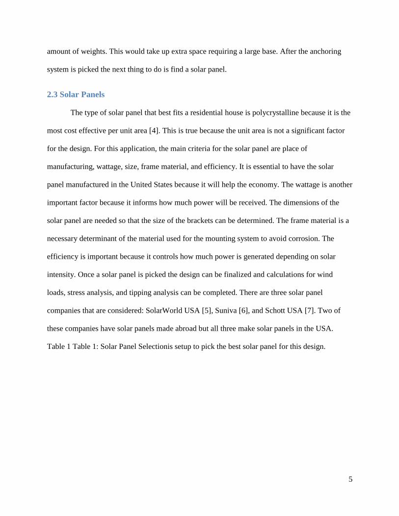
2.3 Solar Panels
The type of solar panel that best fits a residential house is polycrystalline because it is the
most cost effective per unit area [4]. This is true because the unit area is not a significant factor
for the design. For this application, the main criteria for the solar panel are place of
manufacturing, wattage, size, frame material, and efficiency. It is essential to have the solar
panel manufactured in the United States because it will help the economy. The wattage is another
important factor because it informs how much power will be received. The dimensions of the
solar panel are needed so that the size of the brackets can be determined. The frame material is a
necessary determinant of the material used for the mounting system to avoid corrosion. The
efficiency is important because it controls how much power is generated depending on solar
intensity. Once a solar panel is picked the design can be finalized and calculations for wind
loads, stress analysis, and tipping analysis can be completed. There are three solar panel
companies that are considered: SolarWorld USA [5], Suniva [6], and Schott USA [7]. Two of
these companies have solar panels made abroad but all three make solar panels in the USA.
Table 1 Table 1: Solar Panel Selectionis setup to pick the best solar panel for this design.

6
Table 1: Solar Panel Selection
Company Type of Solar
Panel Wattage
Dimensions
(in)
Frame
Material
From
Hole to
Hole
(in)
Weight
(lbs.)
Efficiency
(%)
SolarWorld USA/
Sunmodule Plus Polycrystalline 240 39.41X65.94
Clear
anodized
aluminum
65.94 46.7 14.31
Suniva Polycrystalline 240 39.1X64.6
Anodized
aluminum
alloy
33.86 43.21 14-15
Schott Perform 245 Polycrystalline 240 39.09X66.34 Anodized
aluminum 31.9 41.5 14.3
After looking at all the options Schott Perform 240 was chosen for the purpose of this
design, Figure 3 [7]. This solar panel was picked because it was the lightest and relatively
efficient. Information on the dimensions on the mounting holes was also easily accessible.
Figure 3: Solar Panel

7
3.0 Design Specifications
3.1 Function and Performance
Must be have angle adjusting capabilities ranging from 0˚ to 90˚
A manual must be provided to set up the systems for all of its needs
Must be able to function throughout the USA and its territories
The mounting system must be placed on a flat surface
Mounting system must be safely secured to the ground
3.2 Safety
The mounting system should not tip over
The solar panels must be securely fastened to the mounting system
3.3 Operating Characteristics
Must be able to have a solar panel mounted on top
3.4 Operating Environment
The material used to build the mounting system needs to withstand a temperature of -
50⁰F to 150⁰F
Must withstand a category 2 hurricane (96-110 mph)
It must withstand snow, ice and rain
Material must be corrosion resistant
3.5 Manufacturability
Must be easy and cost effective fabricated
Must be manufactured locally
Must be packaged in a compact box
o Total weigh of package should be less than 100 lbs.
3.6 Assembly
Manual must be included and have easy to understand directions
Easily put together by a non-engineer person (i.e. a lawyer)
3.7 Durability
The mounting system needs to support 80 lbs.
Should function for 20 yrs. in the environment of use
3.8 Cost
Total sale cost must be less than $1,500

8
4.0 Design Process
4.1 Initial Designs
4.1.1 Design 1
Design 1’s (Figure 4) main three focuses are adjustability, support and anchoring. It is a
four legged design with each leg adjustable to allow for angle change of the solar panel. Each of
the four legs comes in two pieces, the base and the support piece. The base piece is where it is
anchored to the ground and slides into the support piece. The support piece is connected to a 180
degree adjustable joint at the top that connects to the frame of the solar panel. The design adjusts
in 10 degree increments by pushing a spring loaded pin. To make the adjustment the front legs
slide down or up one hole and the back legs slide in the opposite direction.
To increase the support of this design each of the four legs has a base twice the cross
sectional area of the pole. In addition there are four square bars that connect in a rectangular
pattern from one leg to another. This greatly increases the stability of the mount because the bars
keep the legs from bowing in or out. The last main focus for this design is how to anchor the
mount to the ground. Through researching different anchoring systems the one found best for
this design was using an auger stake. There are four stakes, each threaded on the top, that get
screwed into the ground. Once they are screwed in the ground the base of each leg, which have a
hole in the center, slide on top of the screw and a washer and Figure 4nut are put on and
tightened to secure the mount.

9
Figure 4: Design 1
4.1.2 Design 2
Design 2 is a four pole ground mount system with an X shape bar assembly on the
bottom of the mount as seen in Figure 5.
Figure 5: Design 2
The X shape at the bottom is to secure the four poles from moving. The hole in the X is where an
augur stake would go to secure the mount to the ground as shown in Figure 6. This will keep the
system from tipping over when there is a lot of wind. The dotted lines on the top view (Figure 6)
are the structures under the solar panel that you would not be able to see in an actual top view.

10
Figure 6: Design 2 Top View
This design is adjustable with four poles than can change in five degree increments as seen in
Figure 7. Each pole has pins that can be moved by pushing them in, then locking them on the
desired setting. The design has a center rotation so the front and back legs would have to be
moved in equal but opposite directions to adjust the angle. An issue with this design is that it
would take at least two people to adjust the angles because the poles need to be adjusted at the
same time.
Figure 7: Design 2 Side View

11
4.1.3 Design 3
Figure 8: Design 3
Design 3 is a ground mounted mono pole system that is adjustable about a fixed point as seen
in Figure 8. The parts listed in the figure are labeled by number and listed here:
1. Solar Panel
2. Cross Beams: that bolt to panel and to bracket (x2)
3. Bracket: bolted to cross beams and angle adjuster.
4. Angle Adjuster: bolted to bracket and vertical supports. Uses an adjustable locking pin to
set the appropriate angle of the panel which is printed on the semicircle piece by the
corresponding pin hole. (x2 but only one pin)
5. Vertical Supports: attached to the cap and angle adjuster (x2)
6. Cap: goes atop pole (perhaps bolted unless the weight and friction caused by the system
allow it not to be) and vertical supports are welded to it
7. Pole: attaches system to ground
8. Concrete base (this, however, is not clear in the photo copy of the drawing)
12
This design has a number of benefits. First, it is a relatively simple system because it has
only a few parts therefore there is not much to assemble. The design is easily adjusted by pulling
a pin and rotating the panel. This is a non-strenuous action because the panel weight is centered
over the system and therefore very little force is needed to adjust the angle. The design can be
located on a slant, such as a hill, provided that the pole is placed in cement vertically upward.
This design, however, is not without issues. Firstly, the customer has to buy, mix, and
pour concrete which can be laborious and might result in a crooked panel. Another issue is that
once the pole is cemented it will be difficult to relocate. This design also accounts for alternative
versions to the base. Instead of a concrete base, the pole could be inserted into a metal foot that
would have cement block ballasts placed on top to prevent the system from sliding and tipping
over.
4.2 Design Matrix
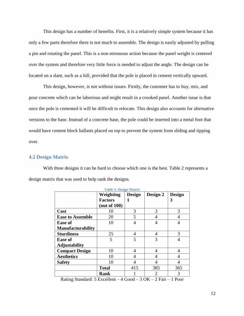
With three designs it can be hard to choose which one is the best. Table 2 represents a
design matrix that was used to help rank the designs.
Table 2: Design Matrix
Weighting
Factors
(out of 100)
Design
1
Design 2 Design
3
Cost 10 3 3 3
Ease to Assemble 20 5 4 4
Ease of
Manufacturability
10 4 4 4
Sturdiness 25 4 4 3
Ease of
Adjustability
5 5 3 4
Compact Design 10 4 4 4
Aesthetics 10 4 4 4
Safety 10 4 4 4
Total 415 385 365
Rank 1 2 3
Rating Standard: 5 Excellent – 4 Good – 3 OK – 2 Fair – 1 Poor

13
The designs were put up against factors that were important for the system. The top
factors are sturdiness and ease of assembly. Each factor was weighted at a certain percentage all
totaling 100. The design was rated, for how well it followed that factor, from 1-5. Then the factor
was multiplied by the rate. Total rates were added up for each design. For example, in Design 1
cost was rated as a 3 with a weight of 10% totaling 30. After everything was multiplied and
added the designs were ranked from 1-3 where 1 being the best and 3 being the worst. From the
design matrix Design 3 was found to be the best design followed by Design 2, then Design 1.
Design 3 was chosen to be advanced in the design process.
4.3 Iterations
After choosing Design 3 using the design matrix the design process was far from over;
the pole mount design went through many iterations before the final design came to fruition.
Some of the parts in the design went through many changes others stayed relatively the same and
still others were emitted from the design completely.
4.3.1 Iteration 1
The original design shown in the sketch called for a round pole set in cement to be fitted
with a cap. On this cap were two vertical supports which then attached to twin semi-circle angle
adjusters these were then bolted to a bracket. This bracket had cross beams on either end which
then were bolted to the solar panel. This configuration, however, did not last long because before
the sketched design could be completely modeled within SolidWorks the group had a meeting
with AMPL employees where the design was refined further. At this meeting the AMPL
employees questioned whether the circular nature of the pole would lead to rotational movement
of the panel where the pole and cap meet. The simplest fix for this was to use a square pole in
order to avoid this problem without causing major design changes or increasing final product

14
cost dramatically. Another problem discussed was the cement anchoring and it was decided that
it would be best to change to a trough to which the pole could be attached. These changes were
made quickly and the first iteration was complete which can be seen in Figure 9. To see
individual parts go to Appendix A, Iteration 1.
Figure 9: Iteration 1
4.3.2 Iteration 2
This iteration of the design did not differ much from the previous iteration. During this
period, experiments with the cap were being performed in order to eliminate the need for the
vertical supports. At this juncture it was not possible to eliminate the vertical supports because
15
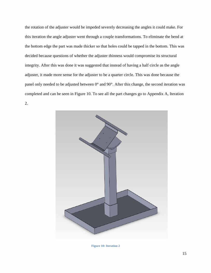
the rotation of the adjuster would be impeded severely decreasing the angles it could make. For
this iteration the angle adjuster went through a couple transformations. To eliminate the bend at
the bottom edge the part was made thicker so that holes could be tapped in the bottom. This was
decided because questions of whether the adjuster thinness would compromise its structural
integrity. After this was done it was suggested that instead of having a half circle as the angle
adjuster, it made more sense for the adjuster to be a quarter circle. This was done because the
panel only needed to be adjusted between 0° and 90°. After this change, the second iteration was
completed and can be seen in Figure 10. To see all the part changes go to Appendix A, Iteration
2.
Figure 10: Iteration 2
16
4.3.3 Iteration 3
The third iteration was a result of another meeting with AMPL. When the newest design
of the angle adjuster was explained to the company, they expressed concerns that it would be too
expensive because the metal was very thick. They also were not sure they would be able to get it
pressed and instead would have to get the piece milled which would drive price up further. In
this meeting everyone brainstormed for ways to solve this problem; what eventually arose were
some comprehensive changes. The first change was to make the adjuster out of a thinner metal
and to change it from twin adjusters to a single adjuster piece that would be bent around the pole.
This change allowed for an elimination of the bracket in order to save materials and cost without
compromising structural integrity. The next change was eliminating the cap part and instead
having the pole come to a point with holes drilled through it. The final change was to make the
lattice of cross beams to fit the panel better. To do this, the lattice was comprised of two lengths
of Unistrut (which would provide adjustment to fit different panels) and two slotted cross beams
in order to allow different panels with different mount holes (it was found that a number of solar
panels have mounting holes that only differ in position by a few inches). These changes were put
into SolidWorks, but in doing so it became clear that the point of the pole would cause clearance
issues for the angle adjuster. To alleviate this problem, two solutions became clear: either round
off the point or to flatten off the top. The rounding option seemed to be difficult to machine so
the flattening option was what was modeled. This created a problem where the adjuster would
collide with the pole before it reached the 80° through 90° holes. This was acceptable, however,
because as will be shown later the only areas that get near using those holes would be in Alaska
and in the winter. These changes were made to the CAD models and the final product can be
seen in Appendix A, Iteration 3.

17
4.4 Final Design
The final design was changed a little further from the last iteration. Instead of having the
pole come to a flattened triangle, it was modeled so the pole would have holes for the angle
adjuster offset to a side of the pole as seen in Appendix B. This would allow clearance for the
angle adjuster and simultaneously allow for the elimination of the strange shape of the pole in the
last iteration, which would have been more difficult to manufacture (Figure 11).
Figure 11: Final Design Assembly Side View

18
Figure 12: Final Design Assembly Isometric View
The trough-like base will be made of thin sheet of metal and then a sheath for the pole
will be welded to this. In this base the buyer/assembler will place bricks to get the structure
anchored. This design also allows for the buyer/assembler to have the option of filling the base
with other materials (i.e. sand, rocks, colored bricks) or digging a small trench in which to place

19
the base and then covering it with soil (this makes it possible to be placed in a garden vastly
improving the aesthetics). The pole will also be able to be easily removed from the base allowing
the owner to transport the set up inside easily in case of extreme weather conditions. Figure 12
represents the final design and analysis was performed to test the integrity of the design.
5.0 Design Analysis
5.1 Tilt Angles
The orientation and tilt position of the solar panel has a great effect on the amount of
solar radiation absorbed and therefore the energy it can produce during the day. Since the ground
solar mounting system is going to be in a fixed location, the system should be oriented towards
true south to maximize the amount of energy collected [8]. The optimum tilt angle is determined
by the latitude of each state, the approximate average latitude of each state is determined using
the World Atlas [9]. Taking into consideration the entire United States, Alaska has the highest
tilt angle and Puerto Rico has the lowest tilt angle as seen in Appendix C. Experiments show that
changing the tilt angle based on the latitude to +15° (±2.5°) during winter and -15° (±2.5) during
summer increases the amount of energy produced by the solar panel [10]. For the purpose of the
design of the mounting system, it is ideal to have an angle adjuster that can adjust from 0° to 90°
at 5° increments to accommodate for all states and the ±15° (±2.5°). Once the tilt angles have
been determined the next thing to be analyzed are the wind loads on the solar panel.
5.2 Wind Loads
There have been various studies on the effects of wind loads on solar arrays. For the
purpose of this design, it is important to determine the maximum wind load exerted on the single
solar panel ground mounting system. The theoretical equation, described in Section 5.2.1 Method

20
I Wind Load Calculations, is used to determine the perpendicular force exerted on the pole of the
single solar panel ground mounting system [11].
5.2.1 Method I Wind Load Calculations
(Eq. 1)
Where:
the wind speed, m/s
S= the surface area of the photovoltaic panel, m2
= the inclination of photovoltaic panel
For the purpose of this calculation, an air density at 1 atmospheric pressure and -62.22 °C
temperature is used. This temperature is used because the coldest temperature ever officially
recorded in the USA is -62.22 °C in Alaska [12], and the air density at 1 atmospheric pressure
increases as temperatures decreases. As determined in the design specifications, the design must
withstand Category II hurricane wind conditions. According to the National Weather Service, the
maximum wind speed of a Category II hurricane is 110 mph [13], the wind speed used for this
calculation is 49.1744 m/s. For the purpose of this calculation, the solar panel dimensions of the
SCHOTT PERFORM POLY 240 are used [7]. The surface area of the photovoltaic panel is
1.673 m2. The inclination angle of every state is used, as well as the corresponding summer and
winter inclination angles as described in Section 5.1 Tilt Angles. These variables are summarizes
bellow:
(At 1 atm pressure and -62.22 °C, the density value is interpolated from the
Properties of Air at 1atm Pressure Table [14])
m/s (Category II hurricane wind speed)
S=1.673 m2
(solar panel dimensions 1,685 mm x 993 mm)
= the inclination of photovoltaic panel

21
Taking all these variables into account, the results are shown in Appendix C, Method I.
The calculation results show that the perpendicular force exerted on the pole of the single solar
panel mounting system is the highest in Alaska during the winter. This is due to the high tilt
angle at 78.35° resulting in a wind load of 6,569.78 N; this is the highest wind load that the
design must withstand according to this method.
5.2.2 Method II Wind Load Calculations
The ASCE Standard (ASCE/SEI 7-10) Chapter 29 on “Wind Loads on Other Structures
and Building Appurtenances−MWFRS” describes various ways of calculating wind loads
depending on the building appurtenances [15]. The method used for determining wind loads, on
the single solar panel ground mounting system, is described in the following way according to
the (ASCE/SEI 7-10) Table 29.2-1 Steps to Determine Wind Loads on MWFRS Rooftop
Equipment and Other Structures.
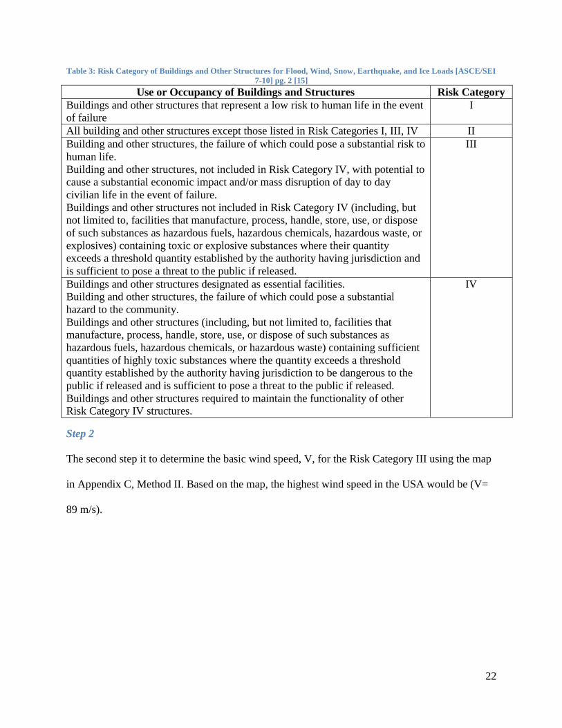
Step 1
The first step is to determine the risk factor of the single solar mounting system structure, see
Table 3. Based on Table 3, the risk category for the single solar panel ground mounting system
structure is determined to be Risk Category III to ensure that the design is conservative.
22
Table 3: Risk Category of Buildings and Other Structures for Flood, Wind, Snow, Earthquake, and Ice Loads [ASCE/SEI
7-10] pg. 2 [15]
Use or Occupancy of Buildings and Structures Risk Category
Buildings and other structures that represent a low risk to human life in the event
of failure
I
All building and other structures except those listed in Risk Categories I, III, IV II
Building and other structures, the failure of which could pose a substantial risk to
human life.
Building and other structures, not included in Risk Category IV, with potential to
cause a substantial economic impact and/or mass disruption of day to day
civilian life in the event of failure.
Buildings and other structures not included in Risk Category IV (including, but
not limited to, facilities that manufacture, process, handle, store, use, or dispose
of such substances as hazardous fuels, hazardous chemicals, hazardous waste, or
explosives) containing toxic or explosive substances where their quantity
exceeds a threshold quantity established by the authority having jurisdiction and
is sufficient to pose a threat to the public if released.
III
Buildings and other structures designated as essential facilities.
Building and other structures, the failure of which could pose a substantial
hazard to the community.
Buildings and other structures (including, but not limited to, facilities that
manufacture, process, handle, store, use, or dispose of such substances as
hazardous fuels, hazardous chemicals, or hazardous waste) containing sufficient
quantities of highly toxic substances where the quantity exceeds a threshold
quantity established by the authority having jurisdiction to be dangerous to the
public if released and is sufficient to pose a threat to the public if released.
Buildings and other structures required to maintain the functionality of other
Risk Category IV structures.
IV
Step 2
The second step it to determine the basic wind speed, V, for the Risk Category III using the map
in Appendix C, Method II. Based on the map, the highest wind speed in the USA would be (V=
89 m/s).
23
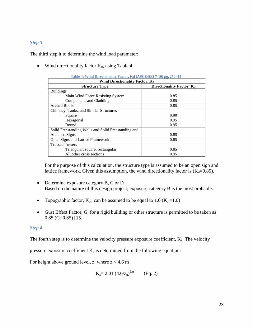
Step 3
The third step it to determine the wind load parameter:
Wind directionality factor Kd, using Table 4:
Table 4: Wind Directionality Factor, Kd (ASCE/SEI 7-10) pg. 250 [15]
Wind Directionality Factor, Kd
Structure Type Directionality Factor Kd
Buildings
Main Wind Force Resisting System
Components and Cladding
0.85
0.85
Arched Roofs 0.85
Chimney, Tanks, and Similar Structures
Square
Hexagonal
Round
0.90
0.95
0.95
Solid Freestanding Walls and Solid Freestanding and
Attached Signs
0.85
Open Signs and Lattice Framework 0.85
Trussed Towers
Triangular, square, rectangular
All other cross sections
0.85
0.95
For the purpose of this calculation, the structure type is assumed to be an open sign and
lattice framework. Given this assumption, the wind directionality factor is (Kd=0.85).
Determine exposure category B, C or D
Based on the nature of this design project, exposure category B is the most probable.
Topographic factor, Kzt, can be assumed to be equal to 1.0 (Kzt=1.0)
Gust Effect Factor, G, for a rigid building or other structure is permitted to be taken as
0.85 (G=0.85) [15]
Step 4
The fourth step is to determine the velocity pressure exposure coefficient, Kz. The velocity
pressure exposure coefficient Kz is determined from the following equation:
For height above ground level, z, where z < 4.6 m
Kz= 2.01 (4.6/zg)2/α
(Eq. 2)

24
α and zg are tabulated in Table 5:
Table 5: Terrain Exposure Constants (ASCE/SEI 7-10) pg. 256 [15]
Terrain Exposure Constants in Metric
Exposure
Α
zg (m)
^
a
^
b
ᾱ
_
b
c
l(m)
_
ϵ
zmin (m)*
B 7.0 365.76 1/7 0.84 1/4.0 0.45 0.30 97.54 1/3.0 9.14
C 9.5 274.32 1/9.5 1.00 1/6.5 0.65 0.20 152.4 1/5.0 4.57
D 11.5 213.36 1/11.5 1.07 1/9.0 0.80 0.15 198.12 1/8.0 2.13
For exposure category B, as determined in Step 3, the values for α and zg are the following:
α=7.0, zg=365.76 m. Now using Equation 2, Kz is calculated as follows bellow:
Kz= 2.01 (4.6/zg)2/α
=0.576
Step 5
The fifth step is to determine the velocity pressure, qz, using the following equation:
qz=0.613 Kz Kzt Kd V2, V in m/s (Eq. 3)
Inputs for Equation 3:
Kz=0.576
Kzt=1.0
Kd=0.85
V=89 m/s
Using the given inputs in Equation 3 yields the following:
qz = 0.613 Kz Kzt Kd V2=2.376 x 10
3
Step 6
The sixth step is to determine the force coefficient, Cḟ, using reference (ASCE/SEI 7-10 pg.311)
[15], Cḟ is assumed to be 1.95.

25
Step 7
The seventh step it to calculate the wind force, F, using Equation 4 (ASCE/SEI 7-10 pg. 308)
[15] bellow:
F = qz G Cḟ As (N) (Eq. 4)
Where:
qz = the velocity pressure
G = gust-effect factor
Cḟ = net force coefficient
As = the gross area of the solid freestanding solid sign (m2)
Inputs for Equation 4:
qz = 2.376 x 10³
G = 0.85
Cḟ = 1.95
As = 1.673 m2
(Solar panel dimensions 1,685 mm x 993 mm)
Solving Equation 4 yields the following:
F=qz G Cḟ As= 6.589 x 10³
Hence, F=6,589 N
5.2.3 Summary of Wind Load Calculations
The calculation results for Method I yielded a wind load of 6,569.78 N and the
calculation for Method II yield a wind load of 6,589 N. These winds loads are off by 20 N which
is a very small difference, confirming the accuracy of the methods. For the purpose of other
calculation in the design analysis, the wind load calculated using Method I, 6,569.78 N, will be
used because it accounts for the tilt angle of the panel.
5.3 Material Analysis
For the selection of the material for the final design the CES EduPack program was used.
Based on the design specifications, the material that was to be used in this design had to
withstand outdoor elements and be strong enough to survive Category II hurricane winds. The
number of materials was narrowed down to a selection of five. The five materials chosen were
Stainless Steel AISI 304 1/4 hard, Painted Steel AISI 1010 low carbon, Aluminum 6061 T4,

26
Rigid PVC, and Treated Wood Oak- alba (l). A table was created using the constants, which
applied to the characteristics which met the needs of the design specifications, of each of the five
materials in Table 6.
Table 6: Material Characteristics
Using the specifications for the design, a set of characteristics for the material was
created. These were used to create several material matrices, one for each major part of the
design and each characteristic was given a percent worth as seen in Appendix D. These
characteristics included (in descending order of importance) strength, cost, corrosion,
availability, machining, shaping, aesthetics, and weight. Basing the data inputted into the
matrices from Table 6, the suitability of each material was calculated by giving a 1-5 rank, 5
being the best, for each characteristic of each material. Once all the matrices were completed
they were consolidated into one matrix to total and average the data and the results are shown in
Table 7.
Material Stainless Steel AISI 304
1/4 hard
Painted Steel AISI 1010 low
carbon
Aluminum
6061 T4 PVC Rigid
Treated Wood Oak-
alba (I)
Density 0.288 lb/in3 0.284 lb/in
3 0.098 lb/in
3 0.049 lb/in
3 0.028 lb/in
3
Young’s Modulus 28.5x10⁶psi 30.5x10
6psi 10.1x10
6psi 0.38x10
6psi 1.95x10
6psi
Flexural Modulus 28.5x10⁶psi 30.5x10
6psi 10.1x10
6psi 0.38x10
6psi 1.78x10
6psi
Shear Modulus 11.2x10⁶psi 11.9x10
6psi 3.9x10
6psi 0.13x10
6psi 0.15x10
6psi
Yield Strength 87.4 ksi 35.3 ksi 16.5 ksi 6.03 ksi 8.16 ksi
Compressive
Strength 87.4 ksi 41.4 ksi 19.5 ksi 5.9 ksi 7.44 ksi
Tensile Strength 87.35 ksi 35.3 ksi 19.5 ksi 6.02 ksi 8.16 ksi
Durability (Fresh
Water) Excellent Excellent Excellent Excellent Acceptable
Durability (Salt
Water) Excellent Excellent Acceptable Excellent Acceptable
Durability (UV
Radiation) Excellent Excellent Excellent Excellent Acceptable

27
Table 7: Material Matrix
Material Availability Cost Aesthetics Corrosion Weight Strength Machining Shaping Total
Percent
worth 10 20 5 15 5 25 10 10 100
Stainless Steel
AISI 304 1/4
hard
5 1 4 5 1 5 4 4 375
Painted Steel
AISI 1010 low
carbon
4 3 4 4 1 4 4 4 365
Aluminum
6061 T4 5 3 4 5 3 3 5 5 395
PVC Rigid 3 4 2 3 4 1 2 1 240
Treated Wood
Oak- alba (l) 3 4 3 3 4 1 2 1 245
Blank Cell
Total of Each Material
Table 7 shows that Aluminum 6061 T4 was the most suitable material followed closely
by Stainless Steel AISI 304 1/4 hard and Painted Steel AISI 1010 low carbon. The last two were
Treated Wood Oak- alba (l) and Rigid PVC which were found to be very unsuitable especially in
the areas of machining, shaping, and strength.
5.4 Stress Analysis
Table 8: Shear Stress
Material Yield Strength
(Pa)
Force needed to
shear 1/4 in bolt (N) 1/2 in bolt
Stainless Steel Alloy
405 170000000 5383.766965 21535.06786
Aluminum 6061
Annealed 5.50E+07 1741.806959 6967.227838
Aluminum 6061 Heat
Treated 276000000 8740.704014 34962.81606
Low End of Wrought
AL on EduPack 95000000 3008.575657 12034.30263
Table 8 describes the necessary forces needed to shear the bolt holding the angle adjuster
to the pole (this bolt is never removed once the mount is set up so it would be the most likely to

28
break). The equation is the standard for shear stress, which is force over area. Four likely
materials were used as well as two different bolt diameters to figure out if the material and bolt
size were appropriate. As is evident, the majority of the choices can withstand the wind force
determined earlier. The best choice for the bolt however is a 6061 aluminum bolt with a diameter
of 3/8 in. because this withstands the wind force with a factor of two. This is ideal because it is
the same material that was chosen in the material analysis.
The next analysis was of the welds in order to determine if the moment created by the
wind force would be enough to break the welds. This was done by finding the moment about the
bottom of the pole created by the wind which was 8,016 Nm. This was compared to the moment
needed to shear the weld. To do this the force required to shear the weld needed to be found.
This was calculated from the endurance limit. It was based on a presentation that described the
failure point for welds to be either 100 kpsi or about half of the materials tensile strength, and to
choose whichever is lower [16]. The tensile strength of Aluminum based on CES EduPack is
about 25 ksi so this is what was used. This worked out to be 12,500 psi (86.18 MPa) but the area
of the weld still needs to be determined to find the shearing force. The weld area is the area about
the pole sheath which will not be a continuous line (to avoid warping of the base during the
welding process) so the equation is: (4.5*2.5)*1/4 (inches). The shearing force works out to be
156382 N and thus gives a moment of 17874 Nm. This is acceptable because the moment
resulting from the wind force is about 16,032 Nm (with a safety factor of two) and the
counteracting moment created by the weld is greater, so the weld will be sufficient in keeping the
structure standing (considering the weld is 4.5 in or .1143m away from the point of rotation).
29
In doing these calculations it is evident that the design accounts for and is well within any
extraneous forces that it might withstand and from here the last analysis is figuring out the
necessary amount of weight to keep the whole structure from tipping over.
5.5 Anchoring Analysis
As seen in the final design, the tray style anchoring is completely above ground, and can
be loaded to adequately counteract wind forces. The size and balancing contents of the tray are
variable, and could potentially be changed on an individual basis for the purpose of aesthetics,
content availability, or desired effectiveness with respect to weight. Some filler materials that
have been discussed are sand, dirt, poured concrete, solid cinderblocks, standard bricks, and
dense or magnetic metals. There are clear benefits and shortcomings of each, but it was decided
to precede with calculations assuming the use of 16in.x 8in.x 4in. solid concrete blocks, available
at Home Depot as counterweight. To adequately determine how many of these blocks are
needed, it is necessary to conduct tipping calculations.
5.5.1 Tipping Calculations
As the design specifications suggest, one of the most important components of
determining the success of the design is to make sure it is capable of withstanding hurricane
Category II force winds without tipping or structurally failing. Solar panels with wattages in the
200-300 watt range are not small devices. They have a large surface area, most averaging about
66 inches by 36 inches. The impact of wind on this panel surface, the pole and the flat faces of
the angle adjuster piece must be considered in the analysis of the supporting mechanisms in the
design. The amount of force experienced by these parts may affect the physical sizing or
anchoring needs of this design.

30
The way that the wind force was calculated was using the following equation [11]:
When the wind is coming from the underside of the angled panel, as seen in Figure 13, the area
being used to find the force is not the full area of the panel, but rather the equivalent area
experiencing the force of the wind if it were perpendicular to the pole.
Figure 13: Side Profile Wind Loading
This assumption is made regarding the panel’s position based on functionality. The panel should
never be facing perpendicular to the ground, and therefore that scenario is eliminated from
consideration. In order to account for the angle of the panel in the wind loading calculations, the
equation is modified [11]:
In this equation the area component of the equation has be multiplied by a factor of sin2ϴ, where
ϴ is the angle of the solar panel with respect to being parallel to (flat) ground.
31
Over the range of locations of possible use, the change in air densities is fairly limited.
The most extreme conditions would be the best to look at because designing for the extremes and
with a safety factor helps create a more effective product in the most common situations. The
most extreme conditions for this application include the air density in Alaska (highest on basis of
low temperature), the velocity of hurricane Category II winds (a design specification), and the
wind coming from the bottom side of the angled panel at an angle of 60 degrees (the highest
reasonable angle).
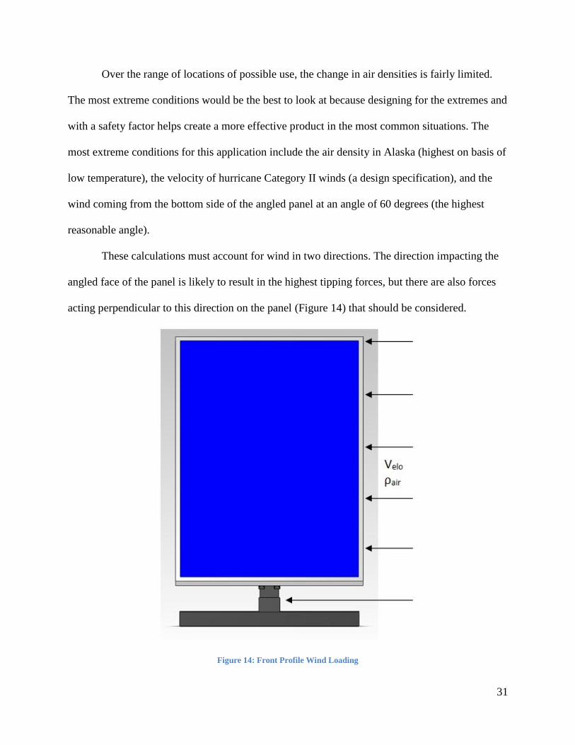
These calculations must account for wind in two directions. The direction impacting the
angled face of the panel is likely to result in the highest tipping forces, but there are also forces
acting perpendicular to this direction on the panel (Figure 14) that should be considered.
Figure 14: Front Profile Wind Loading
32
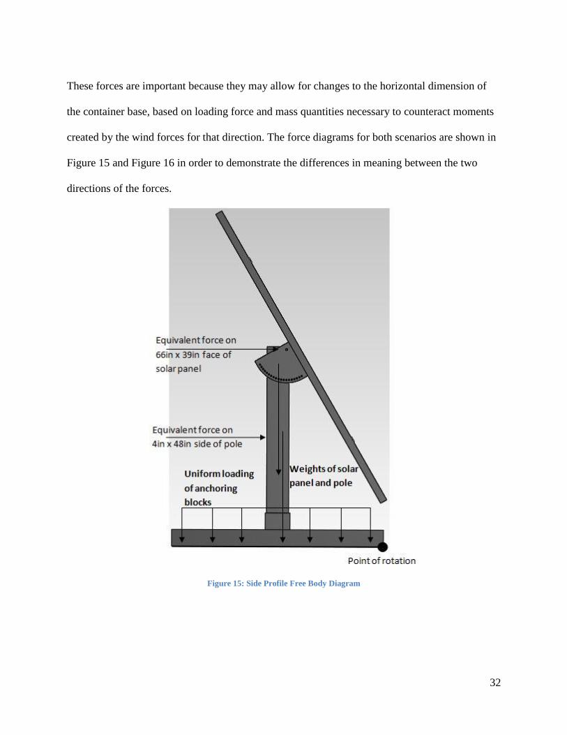
These forces are important because they may allow for changes to the horizontal dimension of
the container base, based on loading force and mass quantities necessary to counteract moments
created by the wind forces for that direction. The force diagrams for both scenarios are shown in
Figure 15 and Figure 16 in order to demonstrate the differences in meaning between the two
directions of the forces.
Figure 15: Side Profile Free Body Diagram
33
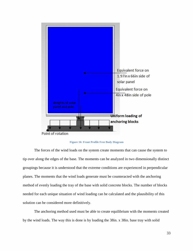
Figure 16: Front Profile Free Body Diagram
The forces of the wind loads on the system create moments that can cause the system to
tip over along the edges of the base. The moments can be analyzed in two dimensionally distinct
groupings because it is understood that the extreme conditions are experienced in perpendicular
planes. The moments that the wind loads generate must be counteracted with the anchoring
method of evenly loading the tray of the base with solid concrete blocks. The number of blocks
needed for each unique situation of wind loading can be calculated and the plausibility of this
solution can be considered more definitively.
The anchoring method used must be able to create equilibrium with the moments created
by the wind loads. The way this is done is by loading the 38in. x 38in. base tray with solid
34
concrete blocks. A full set of equations solving for moments resulting from wind loading are
shown in Appendix E. As discussed in the anchoring section, the concrete blocks are meant to be
easy to place and remove individually, while maintaining an acceptable aesthetic quality as they
keep the system adequately weighted down. The calculations determining the necessary number
of blocks for the wind loads are based off the 16in. x 8in. x 4in. Oldcastle Precast solid concrete
blocks that are implemented in the final anchoring solution. Each of these blocks weighs 33lbs.
which translates to 146.79N of force. For the loading situation in Figure 13, a total of 8674.1N
are needed to create equilibrium in 100mph winds. This means that 60 blocks would have to be
evenly distributed across the 38in. tray. For the loading situation in Figure 14, a total of 747.97N
are needed to create equilibrium in 100 mph winds. This means that only 6 blocks have to be
evenly distributed across the tray.
It is clear that the wind loading situation seen in Figure 13 is driving the anchoring
requirements. Unfortunately, the result of 60 blocks is an unrealistically large number and
suggests two shortcomings. Either the methods being applied for anchoring the system are
ineffective and must be improved, or that the specification regarding wind loading is unrealistic
and should be reassessed for a more reasonable range. Considering that the design was
originally intended for 20 blocks it is reasonable to change the wind load specifications. This
amount of blocks allows for a maximum wind speed of about 60 mph (96.8 km/h). This wind
speed is not Category II but falls within the wind speed of a tropical storm, which is still
significant.
35
6.0 Production and Manufacturing
6.1 Prototype
A prototype was necessary for testing the functionality of the final design. As learned
from the materials matrix aluminum was the best option for the actual design but for this
prototype multiple different materials were used. It was decided to use wood for the base, pole,
and solar panel. The base and pole were made of wood because it was faster and easier to build
then to have shipped out to another machine shop. The solar panel was made of wood to
represent the size and how it fits on the mounting system and it was hard to acquire one. The
angle adjusters were made of aluminum sections to represent how it would work and move. The
remaining parts were made according to the material matrix and SolidWorks model. After all the
parts were designated with a material the manufacturing began.
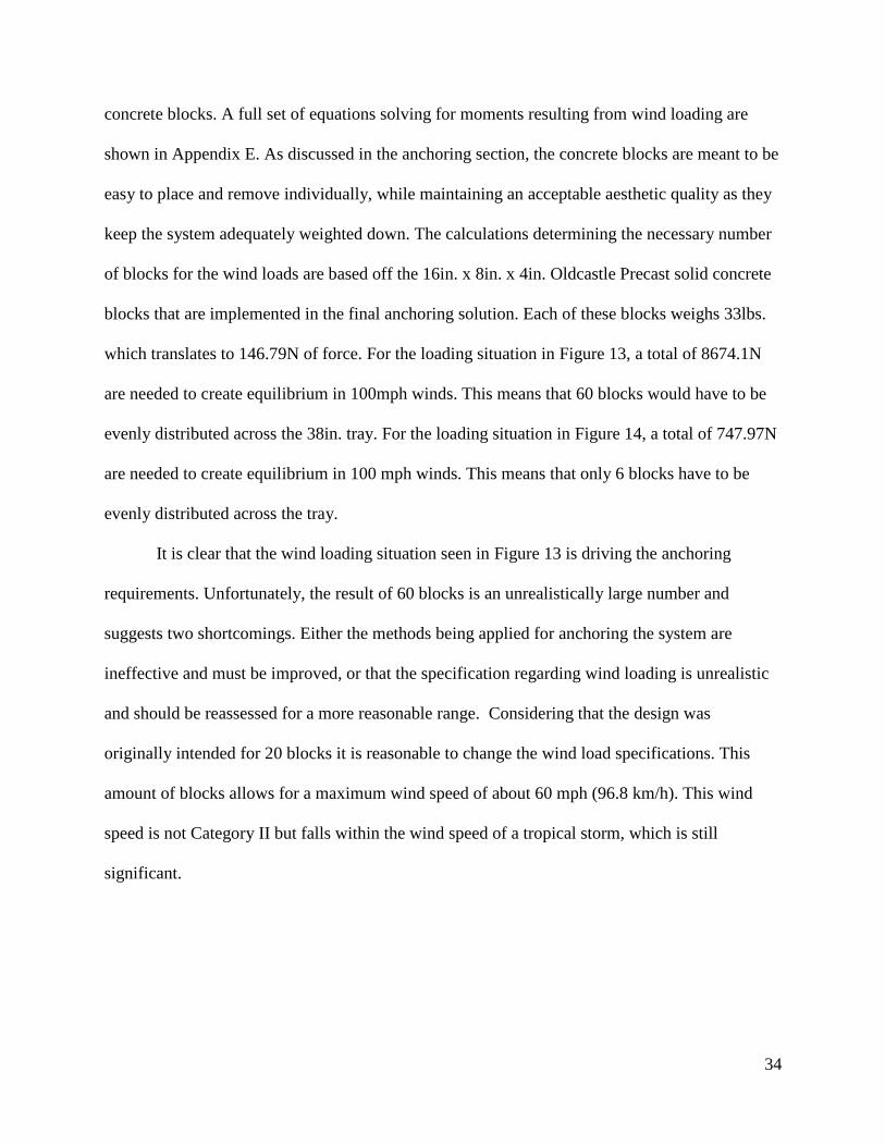
6.1.1 Manufacturing the Prototype
To begin building the prototype it works best to manufacture from the bottom up. The
first thing that was created was the base. It was constructed out of 2X4 and plywood. By using
wood screws the 2X4s were screwed into the plywood to create the edges of the base. Then 2X4s
were screwed in to the middle to use as the support for the pole. Then it was spray painted
metallic silver to give the appearance of aluminum as in Figure 17.
Figure 17: Base

36
The way this part would be manufactured is by taking aluminum sheet metal, stamping out the
shape of the base and bending the corners up to create the edges, then take more aluminum and
weld a square section of the base together to create the pole sheath.
The next part created was the pole. This was made out of a sold square piece of wood.
The piece was cut to the size of the pole in the design. Then the pole is drilled to support the
angle adjuster. The first hole drilled near the top is for the middle of the angle adjuster. The next
hole drilled below is the angle adjusting hole. This pole was spray painted metallic silver to
make it look like aluminum as in Figure 18.
Figure 18: Pole
The pole for the design will be made of square hollowed out aluminum that will be cut from a
long stock. Then the holes will be machined into the pole. This will allow for a perfect straight
alignment so that when the angle adjuster is placed on the pole it can easily be pinned in and able
to move to any angle hole without a struggle.

37
The angle adjuster was the one of the only parts to be machined for the prototype. This
part was created in two steps. The first step was the angle parts and the second step was putting
the adjuster together. The beginning of the first step was to converting the SolidWorks file over
to Esprit so that the part could be machined in the CNC milling machine. This program is used
to design how to cut the part. Two half inch aluminum parts were cut in the CNC machine to
shape the angle adjuster. After the parts were machined the second step began. This step
connects the two machined parts with a piece of cut aluminum sheet metal. To connect these
parts holes in the material had to be drilled and alignment was necessary to get the bolt through.
This was done by clamping the angle adjuster parts to the sheet metal. The adjuster parts each
had two holes drilled and tapped so that a bolt could be screwed in. Then four more holes were
drilled on top to attach the Unistrut. The final look of the angle adjuster is shown in Figure 19.
Figure 19: Angle Adjuster
To connect the angle adjuster to the pole a long bolt was used. To lock the adjuster at a certain
angle another long bolt was used. This long bolt allows the adjuster not to move but can be easily
taken out to change the angle. This part in the final product will be completely made of
aluminum sheet metal. It will be a stamping process where the angle adjuster will be one piece
shaped as in the final SolidWorks model seen in Appendix B, Iteration 3, Figure 30.
38
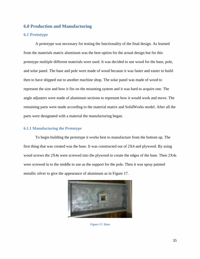
Since the Solar panels can come in different sizes the lattice framework has to also be
adjustable. To accommodate this adjustment, it was best to use Unistrut and slotted bars. The
Unistrut was used to fit different lengths between the vertical mounting holes on a solar panel.
For the prototype a ten foot stock of Unistrut was cut in half and the two pieces were bolted on
top of the four drilled holes of the angle adjuster. The slotted bar was used for the different
lengths between the horizontal mounting holes on the solar panel as in Figure 20. This aluminum
part had slot holes hand-crafted for the prototype to fit the solar panel bolt width; these bars were
fitted onto the Unistrut.
Figure 20: Solar Panel Adjuster Part
The last thing to fashion was the solar panel. The solar panel was cut into the dimensions
of the solar panel used for the design. The material for the solar panel was plywood. To make it
resemble a solar panel it was spray painted with a grid pattern of silver and black paint. Holes
were drilled into the panel so that it would fit on the lattice framework. This final installment

39
completed the prototype. See Figure 21 for the prototype. Assembling the prototype
demonstrated how the actual model should come and what already needs to be assembled.
Figure 21: Final Prototype
6.2 Manufacturer of Choice
Once the design was finalized the next thing to do is find a manufacturer that will
assemble it. Since AMPL wants to keep the manufacturing local thus the machine shop should be
in Massachusetts. The biggest issue was finding a manufacturer that would punch, bend, weld,
and assemble the parts. A list of Massachusetts companies was developed for these criteria. This
list is based on AMPL's location in Boston. Table 9 takes in to account machine shops an hour
and fifteen minutes to zero minutes so that AMPL does not travel too far.

40
Table 9: Manufacturer List
Machine Shop Location What They Do Number Distance
Sinclair MFG Co Norton Metal stamping (508) 222-7440 51min
Roland Teiner Co Everett Metal stamping (617) 387-7800 12 min
New Can Co Holbrook Metal stamping (781) 7671650 28 min
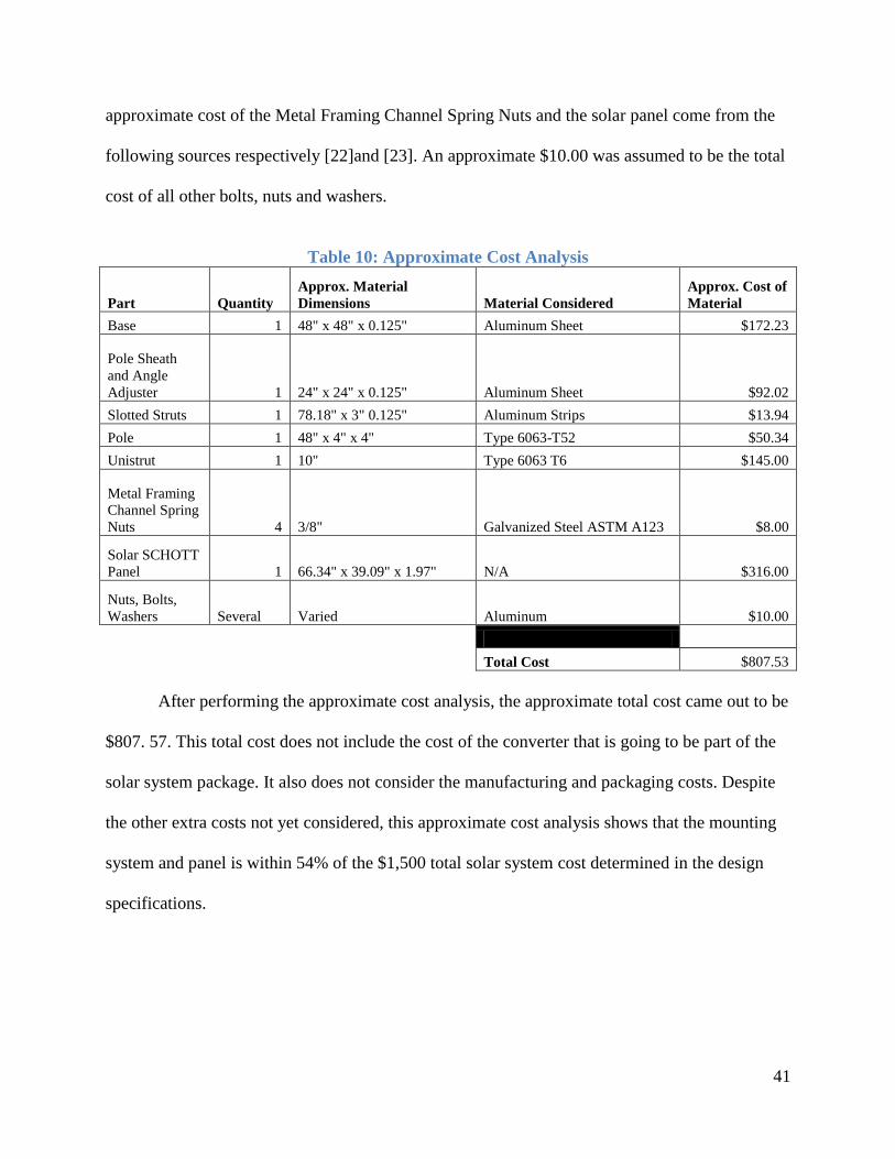
6.3 Cost Analysis The design specifications of the single solar ground mounting system required the retail
price of the whole solar system to be less than $1,500. In order to approximate the price, the
materials needed for the actual design were researched. However, it proved difficult to find the
price of the exact material needed. Therefore, materials that were close enough to the chosen
materials and design dimensions were considered for the purpose of the cost analysis.
For the base, pole sheath, and angle adjuster, a single Aluminum sheet can be used to
make the necessary parts. The material was researched on the MSC Industrial Supply Co.
website and there was not a sheet big enough for all parts. For the base, an Aluminum sheet (48"
x 48" x 0.125") [17] was budgeted for the cost analysis as seen in Table 10. For the pole sheath
and angle adjuster an Aluminum sheet (24" x 24" x 0.125") was used [18]. For the slotted struts
an Aluminum strip (78.18" x 3" 0.125") is needed, but the unit price of the Aluminum strip MSC
#: 06180640 (72" x 3" x 0.125") material is $12.84 each [19]. The price of this material was
divided by 72 to determine the price per inch; the result was then multiplied by 78.18 which is
the length in inches needed for the two slotted struts. The approximate price for the pole was
obtained from Speedy Metals [20]. For the Unistrut, the MSC #: 54055017 [21] unit price of $46
was made of steel so this was divided by the average price per pound of the metal material. This
value was obtained from the CES EduPack program; the result obtained was then multiplied by
the average price per pound of Type 6063 T6 Aluminum which is the metal Unistrut uses. The
41
approximate cost of the Metal Framing Channel Spring Nuts and the solar panel come from the
following sources respectively [22]and [23]. An approximate $10.00 was assumed to be the total
cost of all other bolts, nuts and washers.
Table 10: Approximate Cost Analysis
Part Quantity
Approx. Material
Dimensions Material Considered
Approx. Cost of
Material
Base 1 48" x 48" x 0.125" Aluminum Sheet $172.23
Pole Sheath
and Angle
Adjuster 1 24" x 24" x 0.125" Aluminum Sheet $92.02
Slotted Struts 1 78.18" x 3" 0.125" Aluminum Strips $13.94
Pole 1 48" x 4" x 4" Type 6063-T52 $50.34
Unistrut 1 10" Type 6063 T6 $145.00
Metal Framing
Channel Spring
Nuts 4 3/8" Galvanized Steel ASTM A123 $8.00
Solar SCHOTT
Panel 1 66.34" x 39.09" x 1.97" N/A $316.00
Nuts, Bolts,
Washers Several Varied Aluminum $10.00
Total Cost $807.53
After performing the approximate cost analysis, the approximate total cost came out to be
$807. 57. This total cost does not include the cost of the converter that is going to be part of the
solar system package. It also does not consider the manufacturing and packaging costs. Despite
the other extra costs not yet considered, this approximate cost analysis shows that the mounting
system and panel is within 54% of the $1,500 total solar system cost determined in the design
specifications.

42
6.4 Assembly
When do-it-yourselfers buy items to put together it is expected to have easy assembly
instructions. This solar panel mount will be assembled in 5 Steps. Below is a draft of instructions
that would be found in the packaging that the do-it-yourselfer would use to assemble it.
6.4.1 Assembly Instructions
Solar panel mounting system instructions
Step1:
Place part D and E onto Part C. Screw bolts from package I into holes 1-4. Place the nuts onto
the back of the bolts to lock them in.
It should look like this after. Making this part CDE
Step2:
Place part F and G onto Part CDE and screw bolts from package J into holes 7-10.
It should look like this after. The part is now CDEFG
3
4
43
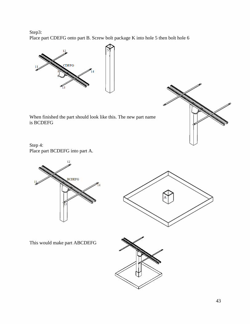
Step3:
Place part CDEFG onto part B. Screw bolt package K into hole 5 then bolt hole 6
When finished the part should look like this. The new part name
is BCDEFG
Step 4:
Place part BCDEFG into part A.
This would make part ABCDEFG
5
44
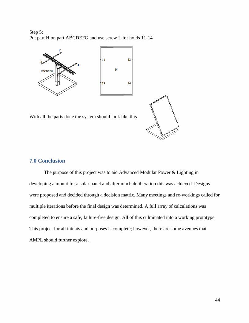
Step 5:
Put part H on part ABCDEFG and use screw L for holds 11-14
With all the parts done the system should look like this
7.0 Conclusion
The purpose of this project was to aid Advanced Modular Power & Lighting in
developing a mount for a solar panel and after much deliberation this was achieved. Designs
were proposed and decided through a decision matrix. Many meetings and re-workings called for
multiple iterations before the final design was determined. A full array of calculations was
completed to ensure a safe, failure-free design. All of this culminated into a working prototype.
This project for all intents and purposes is complete; however, there are some avenues that
AMPL should further explore.

45
8.0 Recommendations
For AMPL to go forward with the product there are a few things that they will need to
know or to figure out. The Schott 240W panel we decided on is largely what we modeled the
design for; however, if AMPL is to choose a different panel minor changes may be needed to be
made to the design. The design fits panels by companies such as SolarWorld, Suniva, Sharp, as
well as Schott but does not fit for Sunpower. These by far are not the only companies to explore
these are just from a preliminary check. The type of brick that is recommended may also not be
ideal for the customer so that factor could be changed. Professor Sisson mentioned using a
silicone adhesive as an option for attaching the panel to the device. This idea was not fully
explored but may be a good option for AMPL to research. The cost analysis we performed was
also introductory and does not account for what the manufacturers would recommend. The
recommendations for manufacturers are also completely up to AMPL’s choice. With these
recommendations as well as the rest of this report AMPL should be able to produce a functional
and appropriate product.

46
Bibliography
[1] L. Devlin, "Solar Power Authority," 20 April 2012. [Online]. Available:
http://solarpowerauthority.com/how-much-does-it-cost-to-install-solar-on-an-average-us-
house/. [Accessed 25 April 2012].
[2] M. J. Moulder and E. S. Taylor, "Solar Panel Mounting Structure, Solar Panel System,and
Methods of Making and Installing Thereof". United States Patent US 6,968,654 B2, 29
November 2005.
[3] T. A. Davis, "Solar Panel Mount". United States Patent 4,300,537, 17 November 1981.
[4] "Solar Juice Blog," 10 June 2010. [Online]. Available: https://solarjuice.com/blog/pv-
panels/monocrystalline-vs-polycrystalline/. [Accessed 4 December 2011].
[5] "Sunmodule SW 240 Poly," Solarworld USA, [Online]. Available: http://www.solarworld-
usa.com/installer-program/products/~/media/Global/PDFs/datasheets/sunmodule-solar-
panel-240-poly-ds.pdf. [Accessed January 2012].
[6] "SUNIVA MVTM SERIES MULTICRYSTALLINE SOLAR MODULES," Suniva,
[Online]. Available: http://www.suniva.com/documents/MVP60Cell_022912.pdf.
[Accessed January 2012].
[7] SCHOTT Solar Inc., "SCHOTT PERFORM POLY Polycrystalline Solar Modules," 2012.
[Online]. Available:
http://www.flimpex.com/downloads/e_schott_perform_poly_datenblatt.pdf. [Accessed 20
December 2011].
[8] S. Armstrong and W. Hurley, "A new methodology to optimise solar energy extraction
under cloudy conditions," Renewable Energy, vol. 35, no. 4, p. 780–787, 8 November 2009.
[9] World Atlas, "World Atlas Explore Your World," 2011. [Online]. Available:
http://www.worldatlas.com/aatlas/latitude_and_longitude_finder.htm. [Accessed November
2011].
[10] D. Z. John Kaldellis, "Experimental investigation of the optimum photovoltaic panels’ tilt
angle during the summer period," Energy, vol. 38, no. 1, p. 305–314, 23 December 2011.
[11] M. Jie, L. Zhizhang and Z. Qingzhu, "Solar photovoltaic panels wind load testing and
analysis," in 2010 International Conference on Mechanic Automation and Control
Engineering (MACE), Wuham, China, 2010.
[12] USA Today, "Each State's Low Temperature Record," 2011. [Online]. Available:
http://www.usatoday.com/weather/wcstates.htm. [Accessed November 2011].
[13] NOAA/ National Weather Service, "Saffir-Simpson Hurricane Wind Scale," National
Hurricane Center, 1 March 2012. [Online]. Available:
http://www.nhc.noaa.gov/aboutsshws.php?large. [Accessed 12 November 2011].
[14] Y. A. Cengel, J. M. Cimbala and R. H. Turner, Fundamentals of Thermal-Fluid Sciences,
4th ed., New York, NY: McGraw-Hill, 2012.
[15] American Society of Civil Engineers, ASCE Standards [ASCE/SEI 7-10] Minimum Design
Loads for Buildings and Other Structures, Reston, VA: American Society of Civil
Engineers, 2010.
[16] J. Glancey, "Weld Design and Specification," [Online]. Available:
http://udel.edu/~jglancey/WeldDesignPresentation.pdf. [Accessed 28 January 2012].

47
[17] MSC Industrial Supply Co., "Alloy 5052-H32 Aluminum Sheets".
[18] MSC Industrial Supply Co., "Alloy 6061 Aluminum".
[19] MSC Industrial Supply Co., "Alloy 6061 Aluminum Aluminum Strips".
[20] Speedy Metals, "4" SQ {A} x 3-3/4" ID {B} x .125" Wall {C} Sq. Tube 6063-T52
Aluminum".
[21] MSC Industrial Supply Co., "Framing Channels Struts - Framing Channels & Struts".
[22] MSC Industrial Supply Co., "Metal Framing Channel Nuts".
[23] Affordable Solar, "Schott Poly 240, 240W Solar Panel".
[24] E. Mehleri, P. Zervas, H. Sarimveis and J. Paly, "Determination of the optimal tilt angle and
orientation for solar photovoltaic arrays," Renewable Energy, vol. 35, no. 11, p. 2468–2475,
November 2010.
[25] "Schott Solar," 2012. [Online]. Available:
http://www.schottsolar.com/us/products/photovoltaics/schott-perform-poly/. [Accessed
January 2012].
[26] Homer TLC, Inc., "The Home Depot," 2011. [Online]. Available:
http://www.homedepot.com/h_d1/N-5yc1v/R-
100125003/h_d2/ProductDisplay?catalogId=10053&langId=-
1&keyword=unistrut&storeId=10051. [Accessed 2 April 2012].

48
Appendices
Appendix A: Design Iterations
Iteration 1
Figure 22: Pole 1
Figure 23: Cap
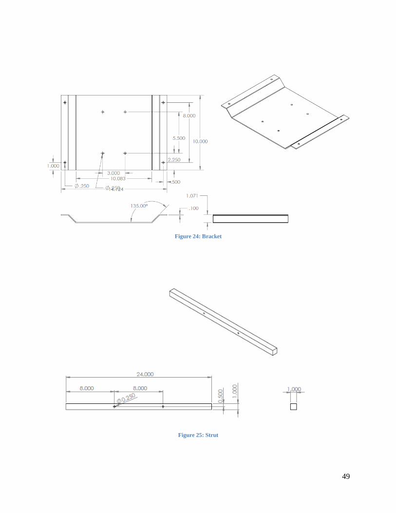
49
Figure 24: Bracket
Figure 25: Strut

50
Figure 26: Base
Iteration 2
Figure 27: Angle Adjuster (180 degrees)
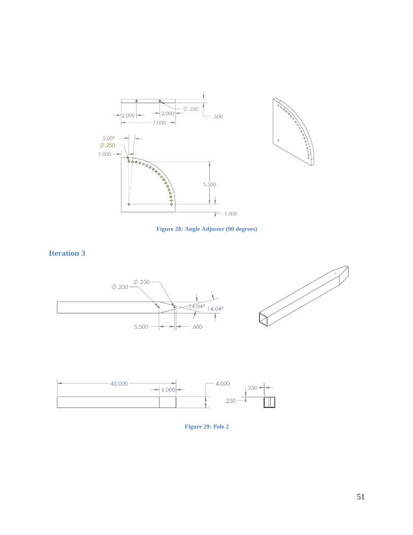
51
Figure 28: Angle Adjuster (90 degrees)
Iteration 3
Figure 29: Pole 2
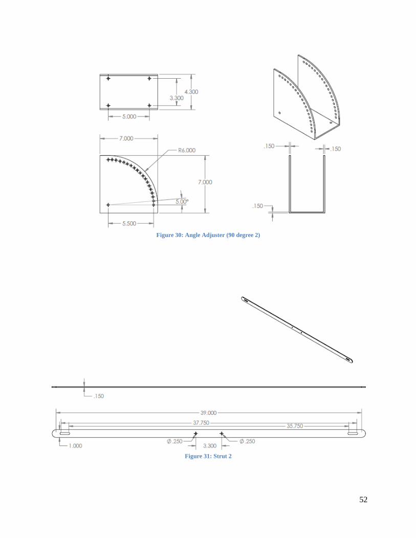
52
Figure 30: Angle Adjuster (90 degree 2)
Figure 31: Strut 2

53
Figure 32: Iteration 3

54
Appendix B: Final Design
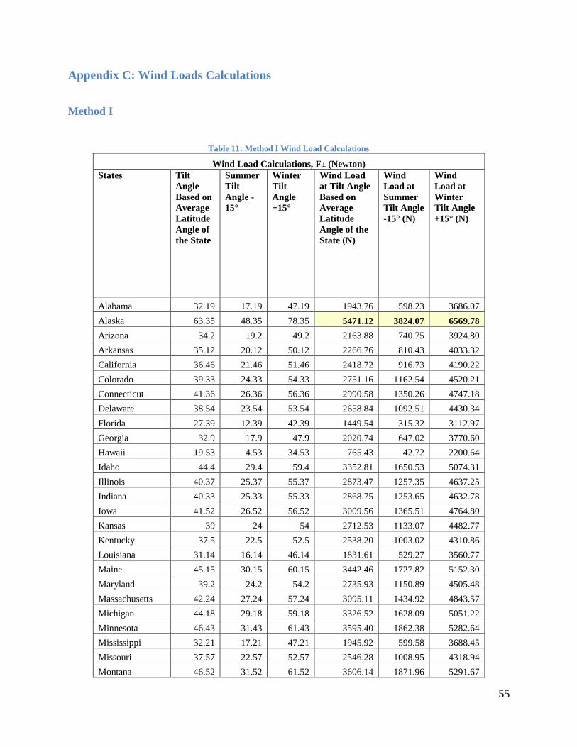
55
Appendix C: Wind Loads Calculations
Method I
Table 11: Method I Wind Load Calculations
Wind Load Calculations, F┴ (Newton)
States Tilt
Angle
Based on
Average
Latitude
Angle of
the State
Summer
Tilt
Angle -
15°
Winter
Tilt
Angle
+15°
Wind Load
at Tilt Angle
Based on
Average
Latitude
Angle of the
State (N)
Wind
Load at
Summer
Tilt Angle
-15° (N)
Wind
Load at
Winter
Tilt Angle
+15° (N)
Alabama 32.19 17.19 47.19 1943.76 598.23 3686.07
Alaska 63.35 48.35 78.35 5471.12 3824.07 6569.78
Arizona 34.2 19.2 49.2 2163.88 740.75 3924.80
Arkansas 35.12 20.12 50.12 2266.76 810.43 4033.32
California 36.46 21.46 51.46 2418.72 916.73 4190.22
Colorado 39.33 24.33 54.33 2751.16 1162.54 4520.21
Connecticut 41.36 26.36 56.36 2990.58 1350.26 4747.18
Delaware 38.54 23.54 53.54 2658.84 1092.51 4430.34
Florida 27.39 12.39 42.39 1449.54 315.32 3112.97
Georgia 32.9 17.9 47.9 2020.74 647.02 3770.60
Hawaii 19.53 4.53 34.53 765.43 42.72 2200.64
Idaho 44.4 29.4 59.4 3352.81 1650.53 5074.31
Illinois 40.37 25.37 55.37 2873.47 1257.35 4637.25
Indiana 40.33 25.33 55.33 2868.75 1253.65 4632.78
Iowa 41.52 26.52 56.52 3009.56 1365.51 4764.80
Kansas 39 24 54 2712.53 1133.07 4482.77
Kentucky 37.5 22.5 52.5 2538.20 1003.02 4310.86
Louisiana 31.14 16.14 46.14 1831.61 529.27 3560.77
Maine 45.15 30.15 60.15 3442.46 1727.82 5152.30
Maryland 39.2 24.2 54.2 2735.93 1150.89 4505.48
Massachusetts 42.24 27.24 57.24 3095.11 1434.92 4843.57
Michigan 44.18 29.18 59.18 3326.52 1628.09 5051.22
Minnesota 46.43 31.43 61.43 3595.40 1862.38 5282.64
Mississippi 32.21 17.21 47.21 1945.92 599.58 3688.45
Missouri 37.57 22.57 52.57 2546.28 1008.95 4318.94
Montana 46.52 31.52 61.52 3606.14 1871.96 5291.67

56
Nebraska 41.29 26.29 56.29 2982.28 1343.60 4739.46
Nevada 38.48 23.48 53.48 2651.85 1087.26 4423.48
New Hampshire 43.11 28.11 58.11 3198.77 1520.47 4937.55
New Jersey 40.3 25.3 55.3 2865.22 1250.88 4629.42
New Mexico 34.58 19.58 49.58 2206.22 769.20 3969.69
New York 40.42 25.42 55.42 2879.37 1261.98 4642.84
North Carolina 35.45 20.45 50.45 2303.96 836.09 4072.09
North Dakota 47.33 32.33 62.33 3702.75 1958.87 5372.08
Ohio 40.25 25.25 55.25 2859.32 1246.26 4623.83
Oklahoma 35 20 50 2253.27 801.19 4019.19
Oregon 43.48 28.48 58.48 3242.92 1557.39 4977.10
Pennsylvania 41.12 26.12 56.12 2962.14 1327.50 4720.67
Rhode Island 41.34 26.34 56.34 2988.21 1348.35 4744.97
South Carolina 33.5 18.5 48.5 2086.46 689.58 3841.88
South Dakota 43.58 28.58 58.58 3254.86 1567.43 4987.75
Tennessee 35.31 20.31 50.31 2288.16 825.16 4055.65
Texas 31.58 16.58 46.58 1878.35 557.70 3613.31
Utah 39.19 24.19 54.19 2734.76 1150.00 4504.35
Vermont 44.33 29.33 59.33 3344.45 1643.38 5066.97
Virginia 37.25 22.25 52.25 2509.36 981.98 4281.96
Washington 47.45 32.45 62.45 3717.04 1971.85 5383.86
West Virginia 38.35 23.35 53.35 2636.72 1075.92 4408.61
Wisconsin 43.47 28.47 58.47 3241.72 1556.39 4976.04
Wyoming 43.4 28.4 58.4 3233.37 1549.38 4968.57
Puerto Rico 18.13 3.13 33.13 663.19 20.42 2045.86
Summary of Results
State
Highest
Angle
Summer
Highest
Angle
Winter
Highest
Angle
Highest
Force (N)
Summer
Highest
Force (N)
Winter
Highest
Force (N)
Alaska 63.35 48.35 78.35 5471.12 3824.07 6569.78
State
Lowest
Angle
Summer
Lowest
Angle
Winter
Lowest
Angle
Lowest
Force (N)
Summer
Lowest
Force (N)
Winter
Lowest
Force (N)
Puerto Rico 18.13 3.13 33.13 663.19 20.42 2045.86

57
Method II
Figure 33: Basic Wind Speeds for Occupancy Category III and IV Buildings and Other Structures (ASCE/SEI 7-10) pg.
248a-b [15]

58
Appendix D: Material Matrix
Table 12: Pole Material Matrix
Table 13: Strut Material Matrix
Table 14: Angle Adjuster Material Matrix
Table 15: Base Material Matrix
Table 16: Bracket Material Matrix

59
Appendix E: Tipping Calculations

60