project manual - storage.googleapis.com · proposals shall be submitted in duplicate upon the blank...
TRANSCRIPT

PROJECT MANUAL
INDIANOLA MISSISSIPPI DEALERSHIP RENOVATIONS WADE, INC.
INDIANOLA, MISSISSIPPI
Prepared By
THE JOHNSON-McADAMS FIRM, P.A. GREENWOOD, MISSISSIPPI
May, 2018
S P E C I F I C A T I O N S

DATE: MAY 2018 PROJECT: INDIANOLA MISSISSIPPI DEALERSHIP RENOVATIONS OWNER: WADE, INC. 1505 HWY. 82 W. GREENWOOD, MS 38930 ARCHITECTS/ENGINEERS: THE JOHNSON-McADAMS FIRM, P.A. 108 WEST MARKET STREET GREENWOOD, MISSISSIPPI 38930 PHONE (662) 455-4943 FAX (662) 455-3381

Table of Contents Page 1
INDIANOLA MISSISSIPPI DEALERSHIP RENOVATIONS WADE INCORPORATED INDIANOLA, MISSISSIPPI
PROJECT TABLE OF CONTENTS FRONT END DOCUMENTS A-1 INVITATION TO BID A-2 FORM OF PROPOSAL A-3 INSTRUCTIONS TO BIDDERS DIVISION 01 – GENERAL REQUIREMENTS 01030 TEMPORARY 01040 STANDARD FORMS 01050 SUPPLEMENTARY CONDITIONS 01060 SPECIAL CONDITIONS 01100 PROJECT CLOSEOUT 01200 FINAL CLEAN-UP 01300 SUBMITTALS 01400 QUALITY REQUIREMENTS 01781 OPERATION AND MAINTENANCE DATA DIVISION 02 – SITEWORK 02000 ENVIRONMENTAL PROTECTION 02225 EXCAVATION, BACKFILLING, AND COMPACTING FOR UTILITIES 02301 EARTHWORK FOR STRUCTURES AND PAVEMENTS 02361 SOIL TREATMENT FOR SUBTERRANEAN TERMITE CONTROL 02539 SANITARY SEWAGE SYSTEMS 02753 PORTLAND CEMENT CONCRETE PAVEMENT DIVISION 03 – CONCRETE 03300 CAST-IN-PLACE CONCRETE DIVISION 04 – MASONRY 04200 UNIT MASONRY

Table of Contents Page 2
DIVISION 05 - METALS 05120 STRUCTURAL STEEL DIVISION 06 - WOOD AND PLASTICS 06410 LAMINATE CLAD ARCHITECTURAL CASEWORK 06611 SOLID POLYMER (SOLID SURFACING) FABRICATIONS DIVISION 07 - THERMAL AND MOISTURE PROTECTION 07600 FLASHING AND SHEET METAL 07920 JOINT SEALANTS DIVISION 08 - DOORS AND WINDOWS 08110 STEEL DOORS AND FRAMES 08210 WOOD DOORS 08330 COILING AND ROLLING DOORS 08580 ALUMINUM INTERIOR SLIDING SERVICE WINDOW DIVISION 09 -FINISHES 09300 CERAMIC TILE DIVISION 13 -SPECIAL CONSTRUCTION 13120 PRE-ENGINEERED METAL BUILDINGS 13341 METAL BUILDING SYSTEMS DIVISION 13 – FIRE SUPPRESSION COVERED ON DRAWINGS DIVISION 15 – HEATING, VENTILATING AND AIR CONDITIONING COVERED ON DRAWINGS DIVISION 15 – PLUMBING COVERED ON DRAWINGS

Table of Contents Page 3
DIVISION 16 -ELECTRICAL 16010 ELECTRICAL GENERAL 16050 WORK IN EXISTING FACILITIES 16110 RACEWAYS 16150 OUTLET BOXES AND JUNCTION BOXES 16250 GROUNDING 16410 CONDUCTORS 16420 PANELBOARDS 16430 DISCONNECTS & SEPARATELY-MOUNTED CIRCUIT BREAKERS 16445 TRANSFORMERS 16460 SWITCHES AND RECEPTACLES 16470 ELECTRICAL STUDIES 16490 SURGE PROTECTIVE DEVICES (SPDs) LOW VOLTAGE AC SURGE PROTECTION FOR ELECTRICAL DISTRIBUTION SYSTEMS 16500 LIGHTING 16510 OCCUPANCY SENSORS 16800 TELEPHONE AND DATA SYSTEMS APPENDIX “A” GEOTECHNICAL REPORT
DRAWINGS (Bound Separately)
-- End of Project Table of Contents --

A-1-- 1 -
A-1 INVITATION TO BID
Sealed bids for INDIANOLA MISSISSIPPI DEALERSHIP RENOVATIONS will be received by the Owner at Wade Incorporated, 1505 HWY 82 W, Greenwood, Mississippi on Thursday, May 31, 2018 at 2:00 P.M. and will be publicly opened and read.
A pre-bid conference will be held at the site on May 18, 2018 at 10:00 A.M. (Architect will receive all parties in the Show Room of the Dealership) General Contractors are required to attend. All interested sub-contractors and suppliers are encouraged to attend.
Selected/Invited General Contractors are:
1. Kenneth Thompson Builders3204 Baldwin RoadGreenwood, MS 38930662-453-7765E-Mail: [email protected]
2. R. C. Construction818 Walnut StreetGreenwood, MS 38930662-453-2424E-Mail: [email protected]
3. Ralph McKnight & Son Construction805 MS-12Kosciusko, MS 39090662-289-6923E-Mail: [email protected]
4. David Smith Construction709 49, MS-3Inverness, MS 38753662-265-6060E-Mail: [email protected]
5. Gary Vaughn Construction27 Anne Drive-in RoadLeland, MS 38756662-378-3730E-Mail: [email protected]
One (1) full size hardcopy and one CD containing PDF files of the Plans and


A-1-- 2 -
specifications may be obtained from the office of the Architect, THE JOHNSON-McADAMS FIRM, P.A., 108 West Market Street, Greenwood, Mississippi 38930 (Ph. 662-455-4943). A One-hundred Dollar ($100.00) non-refundable deposit is required.
Proposals shall be submitted in duplicate upon the blank proposal forms provided with the specifications. Bids on the project must be received on or before the period scheduled for the project and no bid may be withdrawn after the scheduled closing time for the project for a period of ten (10) days. The successful bidder will be required to execute a Performance Bond with a surety company authorized to do business in the State of Mississippi, in the full amount of the contract price. Such bond shall comply with the laws of the State of Mississippi. The Owner may award the contract to the lowest or best bidder therefore, but reserves the right to reject any or all bids, to waive any informalities therein, to determine which is the lowest or best bid. The Owner also reserves the right to hold any or all bids for as long as ten (10) days before awarding contract and no bidder may withdraw his bid during that period of time.
THE JOHNSON-McADAMS FIRM, P.A. GREENWOOD, MISSISSIPPI

A-2-1
A-2 FORM OF PROPOSAL (Submit in duplicate)
Wade Incorporated 1505 Highway 82 West Greenwood, Mississippi 38930 Gentlemen: The undersigned proposes to furnish all labor, materials and equipment necessary to complete the work noted below for INDIANOLA MISSISSIPPI DEALERSHIP RENOVATIONS, INDIANOLA, MISSISSIPPI, in strict accordance with the Documents prepared by THE JOHNSON-McADAMS FIRM, P.A, GREENWOOD, MISSISSIPPI.
SEE DRAWINGS FOR BID DISCRIPTIONS: BASE BID: Base Bid includes all work for the sum of ___________________________________________________($___________)
The undersigned agrees that if notice of acceptance of bid is delivered to him within ten (10) days from date of bid opening, he will promptly execute and deliver a contract in accordance with bid, as accepted by Owner, in the form shown in the Contract Documents. The undersigned agrees to complete work under this contract within 365 consecutive calendar days from the date of "Notice to Proceed” as follows: Enclosed herewith is certified check or bid bond in the amount equal to 5% of the Base Bid, guaranteeing the Owner the execution of a Performance Bond and Contract. The undersigned acknowledges the right of the Owner to accept any proposal, to reject any or all proposals or to waive any informalities in bidding. The Contractor shall pay to the Owner a sum of Five Hundred Dollars ($500.00) per day in liquidated damages for every calendar day the contract exceeds the time specified in the Contract.

A-2-2
The undersigned acknowledges receipt of Addenda numbered: The undersigned hereby certifies that he is familiar with the contents of the Contract Documents for this work and that he has examined the site and accepts existing conditions as those under which the work will be done. Respectfully submitted, ________________________________ By: ____________________________ Title:____________________________ Certificate of Responsibility No.______ DATE _____________________

A-3-1
A-3 INSTRUCTIONS TO BIDDERS 1. REQUIREMENTS A. Interpretations: Should a bidder find discrepancies in or omissions from the drawings or
specifications or be in doubt as to their written meaning, he should immediately notify the Architect who then will send a written instruction or interpretation to all known holders of the documents. Neither the Owner nor the Architect will be responsible for any oral instructions.
B. Addenda: Any addenda to the drawings or specifications issued before or during the time
of bidding shall be included in the proposal and become a part of the contract. C. Substitutions: 1.) Architect will not consider requests for substitutions during bidding. 2.) Within 30 days after date of contract, Architect will consider formal requests from
Contractor for substitution of products in place of those specified. Submit five (5) copies of request for substitution. Include in request:
a.) Complete data substantiating compliance of proposed substitutions with contract documents.
b.) For Products: (1.) Product identification, including manufacturer's name and address. (2.) Manufacturer's literature: Product description, performance and
test data, and reference standards. (3.) Samples. (4.) Name and address of similar projects on which product was used,
and date of installation. c.) For Construction Methods: (1.) Detailed description of proposed method, and (2.) Drawings illustrating methods. d.) Itemized comparison of proposed substitution with product or method
specified. e.) Data relating to changes in construction schedule. f.) Accurate cost data on proposed substitution in comparison with product or
method specified. 3.) In Making Request for Substitution, Bidder/Contractor Represents: a.) He has personally investigated proposed product or method, and
determined that it is equal or superior in all respects to that specified. b.) He will provide the same guarantee for substitution as for product or
method specified.

A-3-2
c.) He will coordinate installation of accepted substitution into work, making such changes required for work to be complete in all respects.
d.) He waives all claims for additional costs related to substitution which consequently becomes apparent.
e.) Cost data is complete and includes all related cost under his contract. 4.) Substitutions Will Not Be Considered If: a.) They are indicated or implied on shop drawings or product data submittals
without formal request submitted in accordance with this section. b.) Acceptance will require substantial revision of contract documents. c.) In the Architect's judgment, the product or material is not equal. 2. BIDDING A. Method of Bidding: See Form of Proposal. B. Subcontracts: The bidder is specifically advised that any persons, firm or other party to
whom it is proposed to award a subcontract under this contract must be acceptable to the Owner.
3. CERTIFICATE OF RESPONSIBILITY A. Certificate of Responsibility Number: Each contractor submitting a bid in excess of
$50,000 must show on his bid and on the face of the envelope containing the bid, his Certificate of Responsibility number, as required by Sections 31-3-15 and 31-3-21, Mississippi Code of 1972, Annotated. If the bid does not exceed $50,000, a notation so stating must appear on the face of the envelope.
B. No bid will be opened, considered, or accepted unless the above information is given as
specified. Sufficient evidence that said Certificate of Responsibility has been issued and is in effect at the time of receiving bids and must be submitted when required by the Owner or the Architect.
4. BID SECURITY Each bid must be accompanied by the bidder's certified check or a bid bond, duly
executed by the bidder as principal and having as surety thereon, a surety company approved by the Owner and signed by an agent resident in Mississippi, in the amount of five percent (5%) of the bid.
5. OPENING OF PROPOSALS Refer to the Invitation to Bid.

A-3-3
6. PREPARATION OF BID A. Conditions of Work: Each bidder must fully inform himself of the conditions relating to
construction of the project and employment of labor thereon. Failure to do so will not relieve a successful bidder of his obligation to furnish all material and labor necessary to carry out the provisions of his contract. Insofar as possible, the contractor must employ methods or means to cause no interruption of or interference with the work of any other contractor.
B. Examination of Site: All bidders, including the general and subcontractors, shall visit the
site of the building, compare the drawings and specifications with any work in place, and inform themselves of all conditions. Failure to visit the site will in no way relieve the successful bidder from furnishing any materials or performing any work required to complete work in accordance with drawings and specifications without additional cost to the Owner.
C. Laws and Regulations: The bidder's attention is directed to the fact that all applicable
state laws, municipal ordinances, and the rules and regulations of all authorities having jurisdiction over construction of the project apply to the contract.
D. Alternates: Each bidder will include Alternates as indicated on Drawings. E. Obligation of Bidder: At the time of opening of bids, each bidder will be presumed to
have inspected the site and to have read and be thoroughly familiar with the drawings and the specifications, including all addenda.
7. PROPOSALS A. Form: Make all proposals on forms provided and fill all applicable blank spaces without
interlineations, alteration or erasure and must not contain recapitulation of the work to be done. No oral, telegraphic, or telephonic proposals will be considered. Any addenda issued during the bidding shall be noted on the proposal form.
B. Withdrawal: Any bid may be withdrawn prior to the above scheduled time for opening of
bids or authorized postponement thereof. Any bid received after the time and date specified will not be considered. Bids may not be withdrawn until 10 days after bid opening.
C. Submittal: Submit bids in duplicate (two) in an opaque sealed envelope marked as
follows: BID FOR INDIANOLA MISSISSIPPI DEALERSHIP RENOVATIONS, WADE INCORPORATED, INDIANOLA, MISSISSIPPI
CERTIFICATE OF RESPONSIBILITY NO.________

A-3-4
D. Telegraphic Modifications: Any bidder may modify his bid by telegraphic
communication at any time provided such communication is received by the Owner prior to the scheduled closing time. Written confirmation must be received within two (2) days from the closing time or no consideration will be given the telegraphic modifications.
8. CONTRACT A. Award of Contract: Contract will be awarded on the basis of the low bid. The Owner
reserves the right to waive irregularities and to reject any or all bids. B. Time of Completion: Bidder must agree to commence work on or before a date specified
in a written "Proceed Order" and to fully complete the project within the calendar days indicated on the Form of Proposal and agreement between owner and contractor.
C. Liquidated Damages for Failure to Enter into Contract: The successful bidder, upon his
failure or refusal to execute and deliver the contract and bond required within ten (10) days after he has received notice of the acceptance of his bid, shall forfeit to the Owner as liquidated damages, the security deposited with his bid.
*** END OF SECTION ***

Section 01030 Page 1
SECTION 01030 TEMPORARY
1. OFFICE
A. Provide a minimum of one field office at least 9 feet by 12 or as necessary for use of job personnel and Architect.
B. Install desk or table, files, drawing racks and shelves as necessary to maintain
order and neatness. Provide a minimum of three chairs or stools.
C. Locate office as directed. Provide means for locking office when work is not in progress. Inform Architect, in writing, of the name, address, and telephone number of person who will have keys to office at all times.
D. Provide lights, heat, and ventilation to permit comfortable use of office.
E. Portable office or trailer meeting these requirements will be acceptable.
2. SHEDS AND STORAGE
A. Provide suitable and sufficient enclosed and covered spaces, with raised flooring, to protect materials and equipment subject to damage by weather or construction.
B. Provide sheds, as necessary, to suitably store materials and equipment needing
limited protection. C. Locate sheds and storage buildings as directed. 3. BARRICADES
A. Erect barricades sufficient to prevent injury to persons or damage to property. Construct to prevent entry of unauthorized persons.
B. Cover trenches and holes when not in use. Erect barriers at sharp changes in
plane more than 4 feet high. 4. SCAFFOLDING
A. Erect and maintain scaffolding, ramps, runways, platforms, guards, rails, stairs, and ladders as necessary for this work.
B. Meet safety requirements of applicable standards, codes, ordinances, and
insurance agencies.
Section 01030 Page 2
C. Provide and maintain lights and signs to prevent damage or injury, keep safety lights burning from dusk to dawn.
5. LIFTING AND HOISTING
A. Provide hoists, temporary elevators, lifts, cranes, and towers necessary for expediting the handling of materials.
B. Install lifting and hoisting equipment to meet applicable safety requirements.
6. SITE ACCESS
General Contractor shall have access to site through an existing gate located at the northeast corner of the site. Any damages to fencing, gate, service yard, or roads shall be promptly repaired.
7. ELECTRICITY
General Contractor shall have access to existing power for adequate supply of electricity for lighting and power for construction purposes.
8. WATER
General Contractor shall have access to existing water supply for adequate supply of water for construction purposes.
9. HEAT
A. Provide heat to prevent damage and to expedite work.
B. Install temporary enclosures to facilitate drying and heating.
C. When fixtures, water services, or equipment items, subject to damage from cold, have been installed, temperature shall be maintained above 50 degrees F.
10. PUMPING AND DRAINING
A. Keep working and storage areas free from water that could cause damage or that would interfere with work.
B. Pump or drain water to designated points. Distribute discharge to prevent
excessive erosion. 11. TELEPHONE
Section 01030 Page 3
A. General Contractor shall provide and pay for telephone for use of persons working on the site. Limit use to business calls.
B. List telephone with information operator in the name of the project and in the
name of the Contractor. 12. REMOVAL
A. Remove temporary work when need for its use has passed.
B. Clean spaces that were occupied by temporary work. Remove debris and rubbish from site.
13. SHOP DRAWINGS & SAMPLES
The number of copies of architectural shop drawings and the number of samples which the Contractor shall submit, and if necessary resubmit, is the number the Contractor requires to be returned plus one which will be retained by the Architect. For mechanical and electrical shop drawings, two copies will need to be retained by the Architect.
14. QUALITY CONTROL
All laboratory testing shall be done by an independent testing laboratory approved by the Architect. The Contractor shall provide for all laboratory testing required by these specifications. One copy of each test report shall be furnished to the Contractor, and two copies to the Architect.
--END OF SECTION--

Section 01040 Page 1
SECTION 01040 STANDARD FORMS
AIA DOCUMENT A201 General Conditions of the Contract for Construction, AIA Document A201, 1997 Edition of the American Institute of Architects, are hereby made a part of this specification to the extent as if bound herein. The General Conditions of the Contract for Construction shall become a part of the Contract and shall apply to all Contractors and Sub-Contractors. Copies of General Conditions may be examined or obtained at the Architect's office. Same have the following content: 1. General Provisions 2. Owner 3. Contractor 4. Administration Of The Contract 5. Subcontractors 6. Construction By Owners Or By Separate Contractors 7. Changes In The Work 8. Time 9. Payments And Completion 10. Protection Of Persons And Property 11. Insurance And Bonds 12. Uncovering And Correction Of Work 13. Miscellaneous Provisions 14. Termination Or Suspension Of The Contract
--End of Section--

Section 01050 Page 1
SECTION 01050 SUPPLEMENTARY CONDITIONS
1 - MEANING OF "AS DIRECTED", "AS APPROVED", etc. Unless otherwise stipulated, the words, "as directed", "as required", "as permitted", or similar phrases signify that the direction, requirement or permission of the architect is intended. The words "approved", "acceptable", "satisfactory", or words of like effect signify approval by, acceptable to, or satisfactory to the architect. The words "or equal", "equal to", etc., signify that the written approval of the architect must be obtained before any substitution may be made for the items specified, well in advance of the time when such items are needed. The architect's approval will not relieve the contractor of responsibility for material, equipment or work later found to be defective or otherwise unsuitable for the work. 2 - MEASUREMENT AND DIMENSIONS Each prime contractor shall verify all dimensions by measurement at the work and shall be responsible for their correctness. 3 - MANUFACTURERS' DIRECTIONS All manufactured articles, materials and equipment shall be applied, installed, connected, erected, used, cleaned and conditioned as directed by the manufacturers, unless herein specified to the contrary. Furnish copies of all printed directions with the materials. 4 - OWNERSHIP OF MATERIALS A - All material and work covered by partial payments made shall thereupon become sole property of the Owner. B - No materials or supplies for the work shall be purchased by the contractor or by any subcontractor subject to any chattel mortgage or under a conditional sale or other agreement by which an interest is retained by the seller. The contractor warrants that he has good title to all materials and supplies for which he accepts partial payment. 5 - INSURANCE A - The contractor shall not commence work under this contract until he has obtained all the insurance required by the provisions of this paragraph and by the General Conditions. B - Certificates of insurance required under General Conditions, Article 11.1.3 and copies of Builder's Risk policies shall be submitted in duplicate to the Architect.
Section 01050 Page 2
C - The contractor shall purchase and maintain the following insurance. The amounts indicated are minimum:
1) Workmen's Compensation: As specified in Art. 11 of the General Conditions and as required by State Law. 2) Public Liability: A minimum of $100,000.00 for one person and $300,000.00 for more than one person in one accident. 3) Property Damage: A minimum of $100,000.00. 4) Owner's Protective Liability Policy in like amounts as set out in 2) and 3) above. Said policy shall name the owner and architect as insured’s. 5) Fire and Extended Coverage, including Vandalism and Malicious Mischief: The full amount of the Contract.
D - Justifiable delays, such as strikes, act of God, etc., caused by conditions beyond the control of any prime contractor, which in turn delays other prime contractors, shall not be considered as constituting a cause for claiming damages therefor from either the prime contractor or the Owner. 6 - RESPONSIBILITY OF CONTRACTOR TO ACT IN EMERGENCY In case of an emergency which threatens loss or injury of property and/or safety of life, the Contractor shall act, without previous instructions from the Owner or Architect, as the situation may warrant. He shall notify the Architect thereof immediately thereafter. Any compensation claimed by the Contractor, together with substantiating documents in regard to expense; shall be submitted to the Owner through the Architect and the amount of compensation shall be determined by agreement. 7 - COOPERATION All Prime Contractors and all Subcontractors shall coordinate all work, one with the other so as to facilitate the general progress of the work. Each trade shall afford all other trades every reasonable opportunity for the installation of their work. 8 - LATENT CONDITIONS If, in the performance of the contract, latent conditions at the site are found to be materially different from those indicated by the Specifications, or unknown conditions not usually inherent in work of the character specified, the attention of the owner shall be called immediately to such conditions before they are disturbed. Upon such notice, or upon his own observation of such conditions, the owner shall promptly make such changes in the specifications as he finds necessary to conform to the different conditions, and any increase or decrease in the cost of the
Section 01050 Page 3
work resulting from such changes shall be adjusted as provided under Article 7 of the AIA General Conditions. 9 - GUARANTEE OF WORK Except as otherwise specified, all work shall be guaranteed against defects resulting from the use of inferior materials, equipment or workmanship for one (1) year from the date of final completion and acceptance of the contract or such time as stipulated in individual sections of the Specifications. Also see Article 12.2 entitled, Correction of Work. 10- PAYMENTS TO CONTRACTOR A - Progress Payments: The Owner shall make payments on account of the Contract as provided therein, as follows:
On or about the 15th of each month one hundred percent (100%) of the value, based on the Contract prices of labor, and materials incorporated in the work and of materials suitably stored at the site thereof or at some other location agreed upon in writing by the parties up to the first day of that month, as estimated by the Architect, less the aggregate of previous payments; and upon substantial completion of the entire work, a sum sufficient to increase the total payments to 100% of the Contract price. B - Acceptance and Final Payment: Final payment shall be due within 30 days after substantial completion of the work provided the work be then fully completed and the contract fully performed.
--End of Section--


Section 01060 Page 1
SECTION 01060 SPECIAL CONDITIONS
1 - ASBESTOS CONTAINING MATERIALS
An asbestos survey has been conducted on the facility. Asbestos containing building materials have not been specified in this project. The use of asbestos-containing building materials in the construction of this project is strictly prohibited. The General Contractor shall be required as a condition for final payment to furnish two (2) affidavits certifying that neither the Contractor nor any of his sub-contractors or material suppliers furnished or installed any asbestos-containing building materials in this project. Failure to comply with this requirement will result in the removal and replacement at the Contractor's expense of any and all materials found to contain asbestos. 2 - EXAMINATION Submission of a bid shall be deemed evidence that Contractor has examined site and is familiar with conditions under which work will be done. Extra payments will not be authorized for work that could have been determined by a careful examination of site and conditions. 3 - COORDINATION The General Contractor shall be responsible for all work. Coordinate work of all trades and subcontractors to expedite progress and avoid interference. Notify trades or subcontractors of readiness for their work to allow adequate time for installation without delaying completion of project. 4 - PERSONNEL AND EQUIPMENT Maintain construction force at site, including supervisors, craftsmen and laborers, sufficient to expedite work to completion date indicated in Contract Documents. Maintain construction equipment at site, in good condition, as necessary to expedite work. 5 - GUARANTY - WARRANTY Contractor shall guarantee materials and workmanship for a period of one year from date of completion except where additional guarantees or warranties are required under the technical sections of the Specifications. Guarantee from General Contractor for labor and materials installed under the Contract shall be in writing to the Owner with a copy sent to the Architect. Deliver material and equipment guarantees or warranties from subcontractors and suppliers to the Architect before final payment. 6 - REQUESTS FOR APPROVAL
Section 01060 Page 2
Any request to substitute material or products other than those specified shall be made in one of the following ways: A - Prior to Bid Opening:
1) Requests for approval of substitution shall be received in the Architect-Engineer's office at least seven (7) days prior to date of opening bids to allow adequate time for checking and answering proposed substitutions. 2) Such requests shall be made in duplicate to facilitate replies. "Speed letters" or “Faxes” are an acceptable manner of requesting approval. 3) Requests shall be accompanied by adequate literature or brochures describing proposed substitutions. 4) Telephone requests will not be considered. 5) Approvals prior to bid opening will be for manufacturer, quality and general arrangement of members only. Contractors are advised that there is not adequate time prior to bid opening for a thorough check of all the component parts of specified systems and equipment. Such approvals must be made after submittal of shop drawings after award of contract. All approvals prior to bid opening will be subject to detail compliance with the Drawings and Specifications.
B - After Award of Contract:
1) Requests for approval of substitutions after award of contract shall be made in the same manner as described above. 2) Requests shall be submitted to the Architect-Engineers for consideration within 28 days after the signing of the contract. Requests received after this time will be automatically rejected, and the contractor will be required to furnish the material as originally specified.
7 - TIME OF COMPLETION
The work shall be started on a date to be set by the Architect in a Proceed Order and shall be fully completed within the following consecutive calendar days thereafter, subject to approved extensions of time as provided in the General Conditions as supplemented and amended.
Base Bid: 365 consecutive days
8 - LIQUIDATED DAMAGES FOR DELAYS If the work is not completed within the time stipulated in above paragraph, Time of Completion, including any extensions of time for excusable delays as provided under the General
Section 01060 Page 3
Conditions, the Contractor and his sureties shall be liable for and shall pay the Owner the sum of Five Hundred Dollars ($500.00) as liquidated damages, but not as a penalty, for each calendar day of delay from the stipulated date of completion, until such work is satisfactorily completed and accepted. 9 - CERTIFICATE OF INSURANCE FORM A - The Certificate of Insurance Form shall be used by all contractors to report and verify compliance with all Insurance Coverage requirements contained in the Contract Documents. B - No construction work shall be started until all required insurance is in force. C - Refer to Paragraph 5, Section 01050, Supplemental Conditions for enumeration of Insurance Requirements. 10 - QUALITY STANDARDS The following statement covering QUALITY STANDARDS governs all sections of the Specifications as explicitly as if repeated in each and every section of the Specifications. QUALITY STANDARDS: Notwithstanding any reference in the specifications to any article, device, product, material, fixture, form or type of construction by name, make, or catalog number, such references shall be interpreted as establishing a standard of quality and shall not be construed as limiting competition; and the Contractor, in such cases, may at his option use any article, device, product, material, fixture, form or type of construction which in the judgment of the Architect expressed in writing is equal to that specified. 11 - FEES AND PERMITS Contractor shall obtain and pay for all fees and permits required of him to carry out the work under this contract. Refer to Paragraph 3.7, Article 3 of the AIA General Conditions of the Contract for Construction.
--End of Section--

Section 01100 Page 1
SECTION 01100 PROJECT CLOSEOUT
1. DESCRIPTION Scope: The work required under this section consists of the final inspections, submitting
of all closeout documents and related items to complete the work indicated on the drawings and described in the General and Special Conditions.
2. FINAL INSPECTIONS A. Architect's Inspection: The Contractor shall make written request for a final
inspection to the Architect; notice to be given ten (10) days prior to the inspection. A list of any deficiencies, compiled by the Architect, will be corrected by the Contractor. If, in his judgment, the project is not ready for a final inspection, the Architect may schedule another inspection.
B. Owner's Inspection: After the Architect has ascertained the project to be
substantially complete; an Owner's inspection will be scheduled within ten (10) days thereafter. The Contractor will have ten (10) days after the acceptance to make any corrections of punch list items and to submit closeout documents.
C. Correction of work before Payment: Contractor shall promptly remove from the
Owner's premises, all materials condemned for failure to conform to the contract, whether incorporated in work or not, and Contractor shall, at his own expense replace such condemned materials with those conforming to the requirements of the contract. Failure to remedy such defects after ten (10) days written notice will allow the Owner to make good such defects and such costs shall be deducted from the balance due the Contractor or charged to the Contractor in the event no payment is due.
3. CLOSEOUT DOCUMENTS Unless otherwise notified, the Contractor shall submit to the Owner through the
Architect, three (3) copies of the following: A. Request for Payment. B. Consent of Surety Company to Final Payment, AIA Form G707. C. Release of Liens and Certification That All Bills Have Been Paid: AIA Form
G706 and G706A. D. Guarantee of Work: Sworn statement that all work is guaranteed against defects
in materials and workmanship for one year from date of Owner's acceptance, except where specified for longer periods.
Section 01100 Page 2
1.) Word the guaranty as follows: "We hereby guarantee all work performed
by us on the above captioned project to be free from defective materials and workmanship for a period of one (1) year or such longer period of time as may be called for in the contract documents for such portions of the work". All guarantees and warranties shall be obtained in the Owner's name.
2.) Within the guaranty period, if repairs or changes are requested in
connection with guaranteed work which, in the use of materials, equipment, or workmanship which are inferior, defective, or not in accordance with the terms of the contract, the Contractor shall promptly, upon receipt of notice from and without expense to the Owner, place in satisfactory condition in every particular, all such guaranteed work, correct all defects therein and make good all damages to the building, site, equipment or contents thereof which, in the opinion of the Owner, is the result of the use of materials, equipment, or workmanship which are inferior, defective or not in accordance with the terms of the contract; and make good any work or materials or the equipment and contents of said buildings or site distributed in fulfilling any such guaranty.
3.) If, after notice, the Contractor fails to proceed promptly to comply with the
terms of the guaranty, the Owner may have the defects corrected and the Contractor and his sureties shall be liable for all expense incurred.
4.) All special guaranties applicable to definite parts of the work stipulated in
the specifications or other papers forming part of the contract shall be subject to the terms of this paragraph during the first year of the life of such special guaranty.
E. Asbestos Containing Building Material: Provide two affidavits certifying that
neither the Contractor nor any of his sub-contractors or material suppliers furnished or installed any asbestos containing building materials in this project.
F. Additional Documents Required: Provide all additional certificates, warranties,
guaranties, bonds, or documents as called for in the individual sections of the specifications.
G. As-Built drawings.
--End of Section--
Section 01200 Page 1
SECTION 01200 FINAL CLEAN-UP
1. SCOPE A. This section encompasses the sweeping, brushing, and other general cleaning of
completed work, and the removal of debris, surplus material, tools not in use, and scaffolding and other equipment no longer needed.
B. Prior to the Architect's final inspection, execute final clean up as follows:
1.) Remove all debris from within the building and at the site.
2.) Leave all of site rake clean.
3.) Fill and grade all ruts caused by Contractor's vehicles.
4.) Remove stains, spots, marks and dirt from finished work. 5.) Clean all glass and glazing. 6.) Replace all broken glass. 7.) Clean all hardware. 8.) Clean all counters, shelving, etc. 9.) Clean all fixtures (electrical, plumbing, etc.) 10. Clean all exterior surfaces.
11.) Entire premises shall be left in a clean condition.
12.) The above 11 items are intended only to cover areas and spaces in which the Contractor does work, or as directly caused by the Contractor.
2. CLEAN-UP DURING CONSTRUCTION All general clean-up and trash removal caused by the execution of work of specific trades
having substantially completed their clean-up work, and therefore, permitted to leave the site shall be performed along with the other general clean-up required by the General Conditions.
3. FINAL CLEAN-UP A. Any damage to glass or the finish of structure of the adjacent Work shall be
Section 01200 Page 2
properly repaired and replaced. All unused construction materials in or about the building and all dirt and rubbish caused by the Work shall be removed. The premises shall be left in a neat, clean and usable condition.
B. The entire area outside of the building shall be clean and raked free of all debris
due to the Work. Remove all debris from the site. No burning will be permitted at the site.
--End of Section--
Section 01300 Page 1
SECTION 01300 SUBMITTALS
1 SUBMITTALS
a) The Contractor shall furnish the Architect with such promptness so as to cause no delay in the work, one copy of reproducible shop drawings as required for the various trades for Architect’s review and approval. Provide the number of copies the Contractor requires to be returned, plus one copy which will be retained by the Architect.
b) The Architect’s approval of shop drawings shall not relieve the Contractor from responsibility for errors and omissions in shop drawings. Shop drawings are the instruments of the Contractor, not the Architect. Drawings and Specifications shall always be final. Contractor shall review and mark revisions to all shop drawings prior to submitting them to the Architect.
2 SAMPLES
a) Within and not later than 30 (thirty) days from the date of the Contract, the General
Contractor shall secure and submit to the Architect for review samples of each kind and grade of materials and finish as noted on/in the Drawings/Specifications. Samples shall be furnished completely and shall accurately represent the work as it is proposed to be installed. The Architect shall notify the Contractor within 7 (seven) days of receipt of the sample as to its approval or rejection. Should samples be rejected, Contractor shall submit corrected samples for approval, and shall continue to do so until approval is given by the Architect. No sample shall be deemed accepted or rejected unless noted as so by the Architect in writing to the Contractor.
b) No allowance will be made at the Owner’s expense or at the Architect’s expense or in
additional time added to the project completion date for delay to the project caused by review of samples or materials, or the Contractor’s negligence in ordering or obtaining materials needed for project completion.
c) It shall be the Contractor’s responsibility to obtain materials at such time as to cause no
delay to the project. No allowance for additional time nor substitution of approved materials will be allowed for Contractor’s negligence in late ordering of materials.
3 PRODUCT DATA
a) Submit three copies of preprinted material such as illustrations, standard schedules, performance charts, instructions, brochures, diagrams, manufacturer’s descriptive literature, catalog data, and other data to illustrate portion of work.
-- End of Section --

Section 01400 Page 1
SECTION 01400 QUALITY REQUIREMENTS
PART 1 GENERAL 1.1 SECTION INCLUDES
A. Quality control and control of installation.
B. Tolerances
C. References.
D. Testing and inspection services.
E. Manufacturers' field services.
F. Examination.
G. Preparation. 1.2 QUALITY CONTROL AND CONTROL OF INSTALLATION
A. Monitor quality control over suppliers, manufacturers, products, services, site conditions, and workmanship, to produce Work of specified quality.
B. Comply with manufacturers' instructions, including each step in sequence.
C. Should manufacturers' instructions conflict with Contract Documents, request
clarification from Architect before proceeding.
D. Comply with specified standards as minimum quality for the Work except where more stringent tolerances, codes, or specified requirements indicate higher standards or more precise workmanship.
E. Perform Work by persons qualified to produce required and specified quality.
F. Verify that field measurements are as indicated on Shop Drawings or as instructed
by the manufacturer.
G. Secure products in place with positive anchorage devices designed and sized to withstand stresses, vibration, physical distortion, or disfigurement.
1.3 TOLERANCES
Section 01400 Page 2
A. Monitor fabrication and installation tolerance control of products to produce acceptable Work. Do not permit tolerances to accumulate.
B. Comply with manufacturers' tolerances. Should manufacturers' tolerances conflict
with Contract Documents, request clarification from Architect before proceeding.
C. Contractor shall approve adjustments of products to appropriate dimensions and shall approve positioning before Contractor secures products in place.
1.4 REFERENCES
A. For products or workmanship specified by association, trade, or other consensus standards, comply with requirements of the standard, except when more rigid requirements are specified or are required by applicable codes.
B. Conform to reference standard by date of issue current on date of Contract
Documents, except where a specific date is established by code.
C. Obtain copies of standards where required by product specification sections.
D. Should specified reference standards conflict with Contract Documents, request clarification from the Architect before proceeding.
E. Neither the contractual relationships, duties, or responsibilities of the parties in
Contract nor those of the Architect shall be altered from the Contract Documents by mention or inference otherwise in any reference document.
1.5 TESTING AND INSPECTION SERVICES
A. Contractor shall employ and pay for services of an independent testing agency or laboratory acceptable to the Architect to perform specified testing. 1. Prior to start of Work, submit testing laboratory name, address, and
telephone number, and names of full time registered Engineer/specialist and responsible officer.
2. Submit copy of report of laboratory facilities inspection made by Materials Reference Laboratory of National Bureau of Standards during most recent inspection, with memorandum of remedies of any deficiencies reported by the inspection.
B. The independent firm will perform tests, inspections and other services specified
in individual specification sections and as required by the Architect. 1. Laboratory: Authorized to operate in location in which Project is located. 2. Testing Equipment: Calibrated at reasonable intervals with devices of an
accuracy traceable to either National Bureau of Standards or accepted values of natural physical constants.

Section 01400 Page 3
C. Testing, inspections and source quality control may occur on or off the project
site. Perform off-site testing as required by the Architect.
D. Reports will be submitted by the independent firm to the Architect and Contractor, in duplicate indicating observations and results of tests and indicating compliance or non-compliance with Contract Documents.
E. Cooperate with independent firm; furnish samples of materials, design mix,
equipment, tools, storage, safe access, and assistance by incidental labor as requested. 1. Notify Architect and independent firm 24 hours prior to expected time for
operations requiring services. 2. Make arrangements with independent firm and pay for additional samples
and tests required for Contractor's use.
F. Testing and employment of testing agency or laboratory shall not relieve Contractor of obligation to perform Work in accordance with requirements of Contract Documents.
G. Re-testing or re-inspection required because of non-conformance to specified
requirements shall be performed by the same independent firm on instructions by the Architect. Payment for re-testing and re-inspection shall be the responsibility of the Contractor.
H. Agency Responsibilities:
1. Test samples of mixes submitted by Contractor. 2. Provide qualified personnel at site. Cooperate with Architect and
Contractor in performance of services. 3. Perform specified sampling and testing of products in accordance with
specified standards. 4. Ascertain compliance of materials and mixes with requirements of
Contract Documents. 5. Promptly notify Architect and Contractor of observed irregularities or non-
conformance of Work or products. 6. Perform additional tests required by Architect. 7. Attend preconstruction meetings and progress meetings.
I. Agency Reports: After each test, promptly submit two copies of report to the
Architect and to Contractor. When requested by Architect, provide interpretation of test results. Include the following: 1. Date issued. 2. Project title and number. 3. Name of inspector. 4. Date and time of sampling or inspection.
Section 01400 Page 4
5. Identification of product and specifications section. 6. Location in the Project. 7. Type of inspection or test. 8. Date of test. 9. Results of tests. 10. Conformance with Contract Documents.
J. Limits On Testing Authority:
1. Agency or laboratory may not release, revoke, alter, or enlarge on requirements of Contract Documents.
2. Agency or laboratory may not approve or accept any portion of the Work. 3. Agency or laboratory may not assume any duties of Contractor. 4. Agency or laboratory has no authority to stop the Work.
1.6 MANUFACTURERS' FIELD SERVICES
A. When specified in individual specification sections, require material or product suppliers or manufacturers to provide qualified staff personnel to observe site conditions, conditions of surfaces and installation, quality of workmanship, start-up of equipment, test, adjust and balance of equipment as applicable, and to initiate instructions when necessary.
B. Submit qualifications of observer to Architect 30 days in advance of required
observations. Observer subject to approval of the Architect.
C. Report observations and site decisions or instructions given to applicators or installers that are supplemental or contrary to manufacturers' written instructions.
D. Refer to Section 01300 - SUBMITTALS.
PART 2 PRODUCTS Not Used. PART 3 EXECUTION 3.1 EXAMINATION
A. Verify that existing site conditions and substrate surfaces are acceptable for subsequent Work. Beginning new Work means acceptance of existing conditions.
B. Verify that existing substrate is capable of structural support or attachment of new
Work being applied or attached.
Section 01400 Page 5
C. Examine and verify specific conditions described in individual specification sections.
D. Verify that utility services are available, of the correct characteristics, and in the
correct locations. 3.2 PREPARATION
A. Clean substrate surfaces prior to applying next material or substance.
B. Seal cracks or openings of substrate prior to applying next material or substance.
C. Apply manufacturer required or recommended substrate primer, sealer, or conditioner prior to applying any new material or substance in contact or bond.
--End of Section--

Section 01781 Page 1
SECTION 01781 OPERATION AND MAINTENANCE DATA
PART 1 GENERAL 1.1 SUBMISSION OF OPERATION AND MAINTENANCE DATA Submit Operation and Maintenance (O&M) Data/Manuals which are specifically applicable to
this contract and a complete and concise depiction of the provided equipment or product. Organize and present information in sufficient detail to clearly explain O&M requirements at the system, equipment, component, and subassembly level. Include an index preceding each submittal. Submit in accordance with this section and Section 01300, "Submittals."
1.1.1 Quantity Submit (5) five sets of the supplier/manufacturers' O&M information specified herein for the
components, assemblies, subassemblies, attachments, and accessories. The items for which O&M Data/Manuals are required are listed in the technical sections which specifies those particular items.
1.1.2 Package Quality Documents must be fully legible. Poor quality copies and material with hole punches
obliterating the text or drawings will not be accepted. 1.1.3 Package Content Data package content shall be as shown in the paragraph titled "Schedule of Operation and
Maintenance Data Packages." For each product, system, or component piece of equipment requiring submission of O&M Data, submit the Data Package specified in the individual technical section.
1.1.4 Delivery Submit O&M Data Manuals to the Contracting Officer for review and acceptance; submit data
specified for a given item within (30) thirty calendar days after the item is delivered to the contract site.
a. In the event the Contractor fails to deliver O&M Data/Manuals within the time
limits set forth above, the Contracting Officer may withhold from progress payments (50) fifty percent of the price of the item with which such O&M Data/Manuals are associated.
Section 01781 Page 2
1.1.5 Changes to Submittals Manufacturer-originated changes or revisions to submitted data shall be furnished by the
Contractor if a component of an item is so affected subsequent to acceptance of the O&M Data. Changes, additions, or revisions required by the Contracting Officer for final acceptance of submitted data, shall be submitted by the Contractor within (30) thirty calendar days of the notification of this change requirement.
1.2 TYPES OF INFORMATION REQUIRED IN O&M DATA PACKAGES 1.2.1 Operating Instructions
Include specific instructions, procedures, and illustrations for the following phases of operation:
1.2.1.1 Safety Precautions List personnel hazards and equipment or product safety precautions for all operating
conditions. 1.2.1.2 Operator Prestart Include procedures required to set up and prepare each system for use. 1.2.1.3 Startup, Shutdown, and Postshutdown Procedures Provide narrative description for each operating procedure including control sequence for
each. 1.2.1.4 Normal Operations Provide narrative description of normal operating procedures. Include control diagrams with
data to explain operation and control of systems and specific equipment. 1.2.1.5 Emergency Operations Include emergency procedures for equipment malfunctions to permit a short period of
continued operation or to shut down the equipment to prevent further damage to systems and equipment. Include emergency shutdown instructions for fire, explosion, spills, or other foreseeable contingencies. Provide guidance on emergency operations of all utility systems including valve locations and portions of systems controlled.
1.2.1.6 Operator Service Requirements Include instructions for services to be performed by the operator such as lubrication,
Section 01781 Page 3
adjustment, inspection, and recording gage readings. 1.2.1.7 Environmental Conditions Include a list of environmental conditions (temperature, humidity, and other relevant data)
which are best suited for each product or piece of equipment and describe conditions under which equipment should not be allowed to run.
1.2.2 Preventive Maintenance Include the following information for preventive and scheduled maintenance to minimize
corrective maintenance and repair. 1.2.2.1 Lubrication Data Include lubrication data, other than instructions for lubrication in accordance with paragraph
titled "Operator Service Requirements":
a. A table showing recommended lubricants for specific temperature ranges and applications;
b. Charts with a schematic diagram of the equipment showing lubrication points, recommended types and grades of lubricants, and capacities; and
c. A lubrication schedule showing service interval frequency.
1.2.2.2 Preventive Maintenance Plan and Schedule Include manufacturer's schedule for routine preventive maintenance, inspections, tests and
adjustments required to ensure proper and economical operation and to minimize corrective maintenance and repair. Provide manufacturer's projection of preventive maintenance work-hours on a daily, weekly, monthly, and annual basis including craft requirements by type of craft. For periodic calibrations, provide manufacturer's specified frequency and procedures for each separate operation.
1.2.3 Corrective Maintenance (Repair) Include manufacturer's recommendations on procedures and instructions for correcting
problems and making repairs. 1.2.3.1 Troubleshooting Guides and Diagnostic Techniques Include step-by-step procedures to promptly isolate the cause of typical malfunctions.
Describe clearly why the checkout is performed and what conditions are to be sought. Identify tests or inspections and test equipment required to determine whether parts and equipment may be reused or require replacement.
Section 01781 Page 4
1.2.3.2 Wiring Diagrams and Control Diagrams Wiring diagrams and control diagrams shall be point-to-point drawings of wiring and control
circuits including factory-field interfaces. Provide a complete and accurate depiction of the actual job specific wiring and control work. On diagrams, number electrical and electronic wiring and pneumatic control tubing and the terminals for each type, identically to actual installation numbering.
1.2.3.3 Maintenance and Repair Procedures Include instructions and list tools required to restore product or equipment to proper condition
or operating standards. 1.2.3.4 Removal and Replacement Instructions Include step-by-step procedures and list required tools and supplies for removal, replacement,
disassembly, and assembly of components, assemblies, subassemblies, accessories, and attachments. Provide tolerances, dimensions, settings and adjustments required. Instructions shall include a combination of text and illustrations.
1.2.3.5 Spare Parts and Supply Lists Include lists of spare parts and supplies required for maintenance and repair to ensure
continued service or operation without unreasonable delays. Special consideration is required for facilities at remote locations. List spare parts and supplies that have a long lead time to obtain.
1.2.4 Corrective Maintenance Work-Hours Include manufacturer's projection of corrective maintenance work-hours including craft
requirements by type of craft. Corrective maintenance that requires participation of the equipment manufacturer shall be identified and tabulated separately.
1.2.5 Appendices Provide information required below and information not specified in the preceding paragraphs
but pertinent to the maintenance or operation of the product or equipment. Include the following:
1.2.6 Parts Identification Provide identification and coverage for all parts of each component, assembly, subassembly,
and accessory of the end items subject to replacement. Include special hardware requirements, such as requirement to use high-strength bolts and nuts. Identify parts by make, model, serial
Section 01781 Page 5
number, and source of supply to allow reordering without further identification. Provide clear and legible illustrations, drawings, and exploded views to enable easy identification of the items. When illustrations omit the part numbers and description, both the illustrations and separate listing shall show the index, reference, or key number which will cross-reference the illustrated part to the listed part. Parts shown in the listings shall be grouped by components, assemblies, and subassemblies. Parts data may cover more than one model or series of equipment. components, assemblies, subassemblies, attachments, or accessories, such as a master parts catalog, in accordance with the manufacturer's standard commercial practice.
1.2.6.1 Warranty Information List and explain the various warranties and include the servicing and technical precautions
prescribed by the manufacturers or contract documents to keep warranties in force. Include warranty information for primary components such as the compressor of air conditioning system.
1.2.6.2 Personnel Training Requirements Provide information available from the manufacturer
that is needed for use in training designated personnel to properly operate and maintain the equipment and systems.
1.2.6.3 Testing Equipment and Special Tool Information Include information on test equipment required to perform specified tests and on special tools
needed for the operation, maintenance, and repair of components. 1.2.6.4 Contractor Information Provide a list that includes the name, address, and telephone number of the General Contractor
and each subcontractor installing the product or equipment. Include local representatives and service organizations most convenient to the project site. Provide the name, address, and telephone number of the product or equipment manufacturers.
1.3 SCHEDULE OF OPERATION AND MAINTENANCE DATA PACKAGES Furnish the O&M Data Packages specified in individual technical sections. The required
information for each O&M Data Package is as follows: 1.3.1 Data Package 1
a. Safety precautions
b. Maintenance and repair procedures
c. Warranty information

Section 01781 Page 6
d. Contractor information
1.3.2 Data Package 2
a. Safety precautions
b. Normal operations
c. Environmental conditions
d. Lubrication data
e. Preventive maintenance plan and schedule
f. Maintenance and repair procedures
g. Removal and replacement instructions
h. Spare parts and supply list
i. Parts identification
j. Warranty information
k. Contractor information 1.3.3 Data Package 3
a. Safety precautions
b. Normal operations
c. Emergency operations
d. Environmental conditions
e. Lubrication data
f. Preventive maintenance plan and schedule
g. Troubleshooting guides and diagnostic techniques
h. Wiring diagrams and control diagrams
Section 01781 Page 7
i. Maintenance and repair procedures
j. Removal and replacement instructions
k. Spare parts and supply list
l. Parts identification
m. Warranty information
n. Testing equipment and special tool information
o. Contractor information 1.3.4 Data Package 4
a. Safety precautions
b. Operator prestart
c. Start-up, shutdown, and post shutdown procedures
d. Normal operations e. Emergency operations f. Operator service requirements
g. Environmental conditions h. Lubrication data
i. Preventive maintenance plan and schedule
j. Troubleshooting guides and diagnostic techniques
k. Wiring and control diagrams l. Maintenance and repair procedures m. Removal and replacement instructions n. Spare parts and supply list
o. Corrective maintenance man-hours
Section 01781 Page 8
p. Parts Identification q. Warranty information r. Personnel training requirements s. Testing equipment and special tool information
t. Contractor information 1.3.5 Data Package 5
a. Safety precautions
b. Operator prestart
c. Start-up, shutdown, and post shutdown procedures
d. Normal operations
e. Environmental conditions
f. Preventive maintenance plan and schedule
g. Troubleshooting guides and diagnostic techniques
h. Wiring and control diagrams
i. Maintenance and repair procedures
j. Spare parts and supply list
k. Testing equipment and special tools
l. Warranty information
m. Contractor information

Section 01781 Page 9
PART 2 PRODUCTS Not used. PART 3 EXECUTION Not used.
-- End of Section --

Section 02000 Page 1
SECTION 02000 ENVIRONMENTAL PROTECTION
PART 1 GENERAL 1.1 APPLICABLE PUBLICATIONS
The publications listed below form a part of this specification to the extent referenced. The publications are referred to in the text by the basic designation only.
ENVIRONMENTAL PROTECTION AGENCY (EPA)
40 CFR 261 Regulations Identifying Hazardous Waste
40 CFR 262 Regulations for Hazardous Waste Generators
DEPARTMENT OF TRANSPORTATION (DOT)
49 CFR 171 Standards for Transportation of Hazardous Materials
49 CFR 172 Hazardous Materials Tables and Regulations 1.2 DEFINITIONS 1.2.1 Sediment
Soil and other debris that has eroded and have been transported by runoff water or wind. 1.2.2 Solid Waste
Rubbish, debris, garbage, and other discarded solid materials, except hazardous waste as defined in paragraph entitled, "Hazardous Waste," resulting from industrial, commercial, and agricultural operations and from community activities.
1.2.3 Sanitary Waste
Waste characterized as domestic sanitary sewage. 1.2.4 Rubbish
Combustible and noncombustible wastes such as paper, boxes, glass, crockery, metal, lumber, cans, and bones.
1.2.5 Debris
Section 02000 Page 2
Combustible and noncombustible wastes such as ashes and waste materials resulting from construction or maintenance and repair work, leaves, and tree trimmings.
1.2.6 Chemical Waste
This includes salts, acids, alkalies, herbicides, pesticides, and organic chemicals. 1.2.7 Garbage
Refuse and scraps resulting from preparation, cooking, dispensing, and consumption of food. 1.2.8 Hazardous Waste
Hazardous substances as defined in 40 CFR 261 or as defined by applicable state and local regulations.
1.2.9 Hazardous Materials
Hazardous materials as defined in 49 CFR 171 and listed in 49 CFR 172. 1.2.10 Landscape Features
Trees, plants, shrubs, and ground cover. 1.2.11 Oily Waste
Petroleum products and bituminous materials. 1.3 ENVIRONMENTAL PROTECTION REQUIREMENTS
Provide and maintain, during the life of the contract, environmental protection as defined. Plan for and provide environmental protective measures to control pollution that develops during normal construction practice. Plan for and provide environmental protective measures required to correct conditions that develop during the construction of permanent or temporary environmental features associated with the project. Comply with Federal, state, and local regulations pertaining to the environment, including water, air, solid waste, hazardous waste and substances, oily substances and noise pollution.
PART 2 PRODUCTS
Not used. PART 3 EXECUTION 3.1 NATURAL RESOURCES
Section 02000 Page 3
Preserve the natural resources within the project boundaries and outside the limits of permanent work. Restore to an equivalent or improved condition upon completion of work. Confine construction activities to within the limits of the work indicated or specified.
3.1.1 Landscape Resources
Do not remove, cut, deface, injure, or destroy existing landscape features without the Professional’s permission. Do not fasten or attach ropes, cables, or guys to existing nearby trees for anchorages, unless authorized by the Professional. Where such use of attach ropes, cables, or guys is authorized, the Contractor shall be responsible for any resultant damage.
3.1.1.1 Protection
Protect existing landscape features which are to remain and which may be injured, bruised, defaced, or otherwise damaged by construction operations. By approved excavation, remove trees with 30 percent or more of their root systems destroyed.
3.1.1.2 Replacement
Remove existing landscape features scarred or damaged by equipment operations, and replace with equivalent, undamaged features. Obtain the Professional's approval before replacement.
3.1.2 Water Resources 3.1.2.1 Oily Wastes
Prevent oily or other hazardous substances from entering the ground, drainage areas, or local bodies of water. Surround all temporary fuel oil or petroleum storage tanks with a temporary earth berm of sufficient size and strength to contain the contents of the tanks in the event of leakage or spillage.
3.1.3 Temporary Construction
Remove traces of temporary construction facilities such as haul roads, work areas, structures, foundations of temporary structures, stockpiles of excess or waste materials, and other signs of construction. Grade temporary roads, parking areas, and similar temporarily used areas to conform with surrounding contours.
3.2 HISTORICAL AND ARCHEOLOGICAL RESOURCES
Carefully protect in-place and report immediately to the Professional historical or archeological items or human skeletal remains discovered in the course of the work. Stop work in the immediate area of the discovery until directed by the Professional to resume work.
Section 02000 Page 4
3.3 EROSION AND SEDIMENT CONTROL 3.3.1 Burnoff
Burnoff of the ground cover is prohibited. 3.3.2 Protection of Erodible Soils
Immediately finish the earthwork brought to a final grade, as indicated or specified. Immediately protect the side slopes and back slopes upon completion of rough grading. Plan and conduct earthwork to minimize the duration of exposure of unprotected soils.
3.3.3 Temporary Protection of Erodible Soils
Provide the following methods to prevent erosion and control sedimentation. 3.3.3.1 Mechanical Retardation and Control of Runoff
Mechanically retard and control the rate of runoff from the construction site. Provide diversion ditches, benches, and berms to retard and divert runoff to protected drainage courses.
3.3.3.2 Seeding
Provide seeding where ground is disturbed. Include topsoil or nutriment during the seeding operation necessary to establish or re-establish a suitable stand of grass.
3.4 CONTROL AND DISPOSAL OF SOLID WASTES
Pick up solid wastes, and place in covered containers which are regularly emptied. Do not prepare or cook food on the project site. Prevent contamination of the site and other areas when handling and disposing of wastes. At project completion, leave the areas clean.
3.4.1 Disposal of Rubbish and Debris
Remove and dispose of rubbish and debris from Owner=s property. 3.4.2 Garbage Disposal
Place garbage in approved containers, disposal of off Owner=s property. 3.4.3 Sewage, Odor, and Pest Control
Dispose of sewage through connection to a municipal or district sanitary sewage system. Where such a system is not available, use chemical toilets or comparably effective units, and periodically empty wastes into a municipal, district, or station sanitary sewage system, or
Section 02000 Page 5
construct and maintain an approved type of adequate sanitary convenience for the use of person employed on the work. Include provisions for pest control and elimination of odors.
3.5 CONTROL AND DISPOSAL OF HAZARDOUS WASTES 3.5.1 Hazardous Waste Generation
Handle generated hazardous wastes in accordance with 40 CFR 262. 3.5.2 Hazardous Waste Disposal
Dispose of hazardous waste in accordance with Federal, State, and local regulations. 3.5.3 Spills of Oil and Hazardous Materials
Take precautions to prevent spills of oil and hazardous material. In the event of a spill, immediately notify the Professional. Spill response shall be in accordance with applicable state regulations.
3.6 PETROLEUM PRODUCTS
Conduct the fueling and lubricating of equipment and motor vehicles to protect against spills and evaporation. Dispose of lubricants to be discarded and excess oils.
3.7 DUST
Keep dust down at all times, including during nonworking periods. Sprinkle or treat, with dust suppressants, the soil at the site, haul roads, and other areas disturbed by operations. Dry power brooming will not be permitted. Instead, use vacuuming, wet mopping, wet sweeping, or wet power brooming. Air blowing will be permitted only for cleaning nonparticulate debris such as steel reinforcing bars.
3.8 NOISE
Make the maximum use of low-noise emission products, as certified by the EPA. Blasting or use of explosives will not be permitted.
-- End of Section --

Section 02225 Page 1
SECTION 02225 EXCAVATION, BACKFILLING, AND COMPACTING FOR UTILITIES
PART 1 GENERAL 1.1 REFERENCES
The publications listed below form a part of this specification to the extent referenced. The publications are referred to in the text by the basic designation only.
AMERICAN SOCIETY FOR TESTING AND MATERIALS (ASTM)
ASTM D 1556 (1990; R 1996) Density of Soil in Place by the Sand-
Cone Method
ASTM D 1557 (1991) Moisture-Density Relations of Soils and Soil-Aggregate Mixtures Using 10-lb (4.54-kg) Rammer and 18-in. (457-mm) Drop
ASTM D 2487 (1993) Classification of Soils for Engineering Purposes
1.2 DEFINITIONS 1.2.1 Backfill
Material used in refilling a cut, trench or other excavation. 1.2.2 Cohesive Materials
Soils classified by ASTM D 2487 as GC, SC, ML, CL, MH, and CH. Materials classified as GM and SM will be identified as cohesive only when fines have a plasticity index greater than zero.
1.2.3 Cohesionless Materials
Soils classified by ASTM D 2487 as GW, GP, SW, and SP. Materials classified as GM and SM will be identified as cohesionless only when the fines have a plasticity index of zero.
1.2.4 Compaction
The process of mechanically stabilizing a material by increasing its density at a controlled moisture condition. "Degree of Compaction" is expressed as a percentage of the maximum density obtained by the test procedure described in ASTM D 1557 for general soil types, abbreviated in this specification as "_____ percent ASTM D _____ maximum density."
Section 02225 Page 2
1.2.5 Granular Pipe Bedding
A dense, well-graded aggregate mixture of sand, gravel, or crushed stone (mixed individually, in combination with each other, or with suitable binder soil) placed on a subgrade to provide a suitable foundation for pipe. Granular bedding material may also consist of poorly graded sands or gravels where fast draining soil characteristics are desired.
1.2.6 In-Situ Soil
Existing in place soil. 1.2.7 Lift
A layer (or course) of soil placed on top of subgrade or a previously prepared or placed soil in a fill or backfill.
1.2.8 Refill
Material placed in excavation to correct overcut in depth. 1.2.9 Topsoil
In natural or undisturbed soil formations, the fine-grained, weathered material on the surface or directly below any loose or partially decomposed organic matter. Topsoil may be a dark-colored, fine, silty, or sandy material with a high content of well decomposed organic matter, often containing traces of the parent rock material.
1.2.10 Unsatisfactory Material
In-Situ soil or other material which can be identified as having insufficient strength characteristics or stability to carry intended loads in the trench without excessive consolidation or loss of stability. Also backfill material which contains refuse, frozen material, large rocks, debris, soluble particles, and other material which could damage the pipe or cause the backfill not to compact. Materials classified as PT, OH, or OL by ASTM D 2487 are unsatisfactory.
1.2.11 Unstable Material
Material in the trench bottom which lacks firmness to maintain alignment and prevent joints from separating in the pipe, conduit, or appurtenance structure during backfilling. This may be material otherwise identified as satisfactory which has been disturbed or saturated.
1.3 SUBMITTALS
Submit the following in accordance with Section 01300, "SUBMITTALS."
Section 02225 Page 3
1.3.1 Field Test Reports
a. Test for moisture-density relation
b. Density and moisture tests
Submit field test data not listed above sufficiently in advance of construction so as not to delay work.
1.3.1.1 Test for Moisture-Density Relation
Submit 7 days prior to commencing utility excavation. 1.3.1.2 Density and Moisture Tests
Submit within 14 days of test date. 1.4 DELIVERY, STORAGE, AND HANDLING
Deliver and store materials in a manner to prevent contamination, segregation, freezing, and other damage.
1.5 CRITERIA FOR BIDDING Base bids on the following criteria:
a. Surface elevations are as indicated.
b. No pipes or other man-made obstructions, except those indicated, will be encountered.
c. The character of the material to be excavated or found in the trench is as indicated.
d. Ground water elevations indicated are those existing at the time subsurface
investigations were made and do not necessarily represent ground water elevation at the time of construction.
e. Suitable backfill in the quantities required is not available at the project site.
f. Blasting will not be permitted.
Section 02225 Page 4
1.6 PROTECTION 1.6.1 Utilities
Movement of construction machinery and equipment over pipes and utilities during construction shall be at the Contractor's risk. Perform work adjacent to non-Owner utilities as indicated in accordance with procedures outlined by utility company. Excavation made with power-driven equipment is not permitted within two feet of any utility or subsurface construction. For work immediately adjacent to or for excavations exposing a utility or other buried obstruction, excavate by hand. Start hand excavation on each side of the indicated obstruction and continue until the obstruction is uncovered or until clearance for the new grade is assured. Support uncovered lines or other existing work affected by the contract excavation until approval for backfill is granted by the Professional. Report damage to utility lines or subsurface construction immediately to the Professional.
PART 2 PRODUCTS 2.1 SOIL MATERIALS
Provide soil materials as specified below free of debris, roots, wood, scrap material, vegetable matter, refuse, soft unsound particles, ice, or other deleterious and objectionable materials.
2.1.1 Backfill
Bring trenches to grade indicated on the drawings using material excavated on the site of this project. This material will be considered unclassified and no testing other than for compaction will be required before use as backfill.
2.1.2 Special Backfill for Structures and Pavements
Backfill trenches under roads, structures, and paved areas as specified in Section 02301, "Earthwork For Structures and Pavements."
2.1.3 Sand
Clean, coarse-grained sand classified as aggregates in accordance with Section 03300, "Cast-In-Place Concrete ."
2.2 BURIED WARNING AND IDENTIFICATION TAPE
Polyethylene plastic and metallic core or metallic-faced, acid- and alkali-resistant, polyethylene plastic warning tape manufactured specifically for warning and identification of buried utility lines. Provide tape on rolls, 3-inch-minimum width, color coded as specified below for the intended utility with warning and identification imprinted in bold black letters

Section 02225 Page 5
continuously over the entire tape length. Warning and identification to read, "CAUTION, BURIED (intended service) LINE BELOW" or similar wording. Color and printing shall be permanent, unaffected by moisture or soil.
Warning Tape Color Codes Yellow: Electric Orange: Telephone and Other Communications Blue: Water Systems Green: Sewer Systems 2.2.1 Warning Tape for Metallic Piping
Acid and alkali-resistant polyethylene plastic tape conforming to the width, color, and printing requirements specified above. Minimum thickness of tape shall be 0.003 inch. Tape shall have a minimum strength of 1500 psi lengthwise, and 1250 psi crosswise, with a maximum 350 percent elongation.
2.2.2 Detectable Warning Tape for Non-Metallic Piping
Polyethylene plastic tape conforming to the width, color, and printing requirements specified above. Minimum thickness of the tape shall be 0.004 inch. Tape shall have a minimum strength of 1500 psi lengthwise and 1250 psi crosswise. Tape shall be manufactured with integral wires, foil backing, or other means of enabling detection by a metal detector when tape is buried up to 3 feet deep. Encase metallic element of the tape in a protective jacket or provide with other means of corrosion protection.
PART 3 EXECUTION 3.1 PROTECTION 3.1.1 Water Removal
Remove water by pumping or other methods to prevent the softening of surfaces exposed by excavation, prevent hydrostatic uplift, and provide a stable trench condition for installation of the utility.
3.1.2 Structures and Surfaces
Protect newly backfilled areas and adjacent structures, slopes, or grades from traffic, erosion settlement, or any other damage. Repair and reestablish damaged or eroded grades and slopes and restore surface construction prior to acceptance. Perform work in accordance with requirements specified in Section 02000 "Environmental Protection."
Section 02225 Page 6
3.2 SURFACE PREPARATION 3.2.1 Stockpiling Topsoil
Strip suitable soil from the site where excavation or grading is indicated and stockpile separately from other excavated material. Locate topsoil so that the material can be used readily for the finished grading. Where sufficient existing topsoil conforming to the material requirements is not available on site, provide borrow materials suitable for use as topsoil. Protect topsoil and keep in segregated piles until needed.
3.2.2 Cutting Pavement, Curbs, and Gutters
Saw cut with neat, parallel, straight lines one foot wider than trench width on each side of trenches and one foot beyond each edge of pits. When the saw cut is within 5 feet of an existing joint, remove pavement to the existing joint.
3.3 GENERAL EXCAVATION AND TRENCHING
Keep excavations free from water while construction is in progress. Notify the Professional immediately in writing if it becomes necessary to remove rock or hard, unstable, or otherwise unsatisfactory material to a depth greater than indicated. Make trench sides as nearly vertical as practicable except where sloping of sides is allowed. Sides of trenches shall not be sloped from the bottom of the trench up to the elevation of the top of the pipe or conduit. Overexcavate soft, weak, or wet excavations as indicated. Use sand placed in 6-inch-maximum layers to refill overdepths to the proper grade. At the Contractor's option, the excavations may be cut to an overdepth of not less than 4 inches and refilled to required grade as specified. Grade bottom of trenches accurately to provide uniform bearing and support for each section of pipe or conduit. Dig bell holes and depressions for joints after trench has been graded. Dimension of bell holes shall be as required for properly making the particular type of joint to ensure that the bell does not bear on the bottom of the excavation. Trench dimensions shall be as indicated or specified.
3.4 BURIED WARNING AND IDENTIFICATION TAPE
Install tape in accordance with manufacturer's recommendations except as modified herein. Bury tape 12 inches below finished grade; under pavements and slabs, bury tape 6 inches below top of subgrade.
3.5 BACKFILLING
Construct backfill in two operations (initial and final) as indicated and specified in this section. Place initial backfill in 6-inch-maximum loose lifts to one foot above pipe or conduit unless otherwise specified. Ensure that initially placed material is tamped firmly under pipe haunches. Bring up evenly on each side and along the full length of the pipe, or conduit. Ensure that no damage is done to the utility or its protective coating. Place the remainder of
Section 02225 Page 7
the backfill (final backfill) in 9-inch-maximum loose lifts unless otherwise specified. Compact each loose lift as specified in the paragraph entitled "General Compaction" before placing the next lift. Do not backfill in freezing weather or where the material in the trench is already frozen or is muddy, except as authorized. Provide a minimum cover from final grade of 2-1/2 feet for water piping, gas mains, storm drains and 2 feet for sewer mains. Where settlements greater than the tolerance allowed herein for grading occur in trenches and pits due to improper compaction, excavate to the depth necessary to rectify the problem, then backfill and compact the excavation as specified herein and restore the surface to the required elevation. Coordinate backfilling with testing of utilities.
3.6 COMPACTION
Use hand-operated, plate-type, vibratory, or other suitable hand tampers in areas not accessible to larger rollers or compactors. Avoid damaging pipes and protective pipe coatings. Compact material in accordance with the following unless otherwise specified. If necessary, alter, change, or modify selected equipment or compaction methods to meet specified compaction requirements.
3.6.1 Compaction of Material in Subcuts or Overexcavations
In soft, weak, or wet soils, tamp refill material to consolidate to density of adjacent material in trench wall. In stable soils, compact to 90 percent of ASTM D 1557 maximum.
3.6.2 Compaction of Backfill
Compact initial backfill material surrounding pipes, cables, conduits, or ducts, to 90 percent of ASTM D 1557 maximum density. Under areas to be seeded or sodded, compact succeeding layers of final backfill to 85 percent of ASTM D 1557 maximum density. For utilities under structures and pavements compact succeeding layers of final backfill as specified under section 02301, Earthwork for Structures and Pavements."
3.7 FINISH OPERATIONS 3.7.1 Grading
Finish to grades indicated within one-tenth of a foot. Provide topsoil in areas to be seeded. Grade areas to drain water away from structures and to provide suitable surfaces for mowing machines. Grade existing grades that are to remain but have been disturbed by the Contractor's operations.
3.8 FIELD QUALITY CONTROL
Test backfill for conformance to specified requirements. Test backfill for moisture-density relations in accordance with ASTM D 1557 as specified herein. Perform at least one of each of the required tests for each material provided. Perform sufficiently in advance of

Section 02225 Page 8
construction so as not to delay work. Provide additional tests as specified above for each change of source. Perform density and moisture tests in randomly selected locations and in accordance with ASTM D 1556.
a. in Trenches: One test per 100 linear feet in each lift.
-- End of Section --

Section 02301 Page 1
SECTION 02301 EARTHWORK FOR STRUCTURES AND PAVEMENTS
PART 1 GENERAL 1.1 REFERENCES
The publications listed below form a part of this specification to the extent referenced. The publications are referred to in the text by the basic designation only.
AMERICAN SOCIETY FOR TESTING AND MATERIALS (ASTM)
ASTM C 33 (1997) Concrete Aggregates
ASTM C 136 (1996; Rev. A) Sieve Analysis of Fine and Coarse
Aggregates
ASTM D 1140 (1997) Amount of Material in Soils Finer Than the No. 200 (75-Micrometer) Sieve
ASTM D 1556 (1990; R 1996) Density and Unit Weight of Soil in Place
by the Sand-Cone Method
ASTM D 1557 (1991) Laboratory Compaction Characteristics of Soil Using Modified Effort (56,000 ft-lbf/ft (2,700 kN-m/m))
ASTM D 2434 (1968; R 1994) Permeability of Granular Soils (Constant
Head)
ASTM D 2487 (1993) Classification of Soils for Engineering Purposes (Unified Soil Classification System)
ASTM D 2855 (1996) Making Solvent-Cemented Joints with Poly
(Vinyl Chloride) (PVC) Pipe and Fittings
ASTM D 2922 (1996) Density of Soil and Soil-Aggregate in Place by Nuclear Methods (Shallow Depth)
ASTM D 2487 (1993) Classification of Soils for Engineering Purposes
(Unified Soil Classification System)
ASTM D 3786 (1987) Hydraulic Bursting Strength of Knitted Goods and Nonwoven Fabrics - Diaphragm Bursting Strength Tester Method
Section 02301 Page 2
ASTM D 4253 (1993) Maximum Index Density of Soils Using a Vibratory Table
ASTM D 4254 (1991) Minimum Index Density and Unit Weight of
Soils and Calculation of Relative Density
ASTM D 4318 (1995; Rev. A) Liquid Limit, Plastic Limit, and Plasticity Index of Soils
ASTM D 4355 (1992) Deterioration of Geotextiles from Exposure to
Ultraviolet Light and Water (Xenon-Arc Type Apparatus)
ASTM D 4491 (1996) Water Permeability of Geotextiles by Permittivity
ASTM D 4533 (1991; R 1996) Trapezoid Tearing Strength of
Geotextiles
ASTM D 4632 (1991; R 1996) Grab Breaking Load and Elongation of Geotextiles
ASTM D 4751 (1995) Determining the Apparent Opening Size of a
Geotextile
ASTM D 4833 (1988; R 1996) Index Puncture Resistance of Geotextiles, Geomembranes, and Related Products
ASTM F 402 (1993) Safe Handling of Solvent Cements, Primers, and
Cleaners Used for Jointing Thermoplastic Pipe and Fittings
ASTM F 758 (1995) Smooth-Wall Poly (Vinyl Chloride) (PVC)
Plastic Underdrain Systems for Highway, Airport, and Similar Drainage
CORPS OF ENGINEERS (COE)
COE EM-385-1-1 (1992) Safety and Health Requirements Manual
1.2 DEFINITIONS 1.2.1 Backfill
A specified material used in refilling a cut, trench, or other excavation, placed at a specified degree of compaction.

Section 02301 Page 3
1.2.2 Capillary Water Barrier
A layer of clean, poorly graded crushed rock, stone, or natural sand or gravel having a high porosity which is placed beneath a building slab with or without a vapor barrier to cut off the capillary flow of pore water to the area immediately below a slab.
1.2.3 Cohesive Materials
Cohesive materials include materials classified by ASTM D 2487 as GC, SC, ML, CL, MH, and CH. Materials classified as GM and SM will be identified as cohesive only when the fines have a plasticity index greater than zero.
1.2.4 Cohesionless Materials
Cohesionless materials include materials classified by ASTM D 2487as GW, GP, SW, and SP. Materials classified as GM and SM will be identified as cohesionless only when the fines have a plasticity index of zero.
1.2.5 Compaction
The process of mechanically stabilizing a material by increasing its density at a controlled moisture condition. "Degree of Compaction" is expressed as a percentage of the maximum density obtained by the test procedure described in ASTM D 1557 for general soil types or ASTM D 4253 and ASTM D 4254 (Relative Density) for isolated cohesionless materials, abbreviated in this specification as "_____ percent ASTM D _____ maximum density."
1.2.6 Controlled Fill and Controlled Backfill
A specified soil mix or gradation of materials constructed to attain maximum bearing strength and minimize consolidation or differential settlement under a load. Controlled fill is sometimes called "structural fill."
1.2.7 Embankment
A "fill" having a top that is higher than adjoining ground. 1.2.8 Excavation
The removal of soil, rock, or hard material to obtain a specified depth or elevation. 1.2.9 Fill
Specified material placed at a specified degree of compaction to obtain an indicated grade or elevation.
Section 02301 Page 4
1.2.10 Hard Material
Weathered rock, dense consolidated deposits or conglomerate materials, (excluding manmade materials such as concrete) which are not included in the definition of "rock" but which usually require the use of heavy excavation equipment with ripper teeth or the use of jack hammers for removal.
1.2.11 In Situ Soil
Existing in place soil. 1.2.12 Lift
A layer (or course) of soil placed on top of a previously prepared or placed soil. 1.2.13 Rock
Solid, homogeneous, interlocking crystalline material with firmly cemented, laminated, or foliated masses or conglomerate deposits, neither of which can be removed without systematic drilling and blasting, drilling and the use of expansion jacks or feather wedges, or the use of backhoe-mounted pneumatic hole punchers or rock breakers; also large boulders, buried masonry, or concrete other than pavement, exceeding 1 cubic yard in volume.
1.2.14 Soil
The surface material of the earth's crust resulting from the chemical and mechanical weathering of rock and organic material.
1.2.15 Subgrade
The material in excavation (cuts) and fills (embankments) immediately below any subbase, base, pavement, or other improvement. Also, as a secondary definition, the level below which work above is referenced.
1.2.16 Topsoil
In natural or undisturbed soil formations, the fine-grained, weathered material on the surface or directly below any loose or partially decomposed organic matter. Topsoil may be a dark-colored, fine, silty, or sandy material with a high content of well decomposed organic matter, often containing traces of the parent rock material. The material shall be representative of productive soils in the vicinity.
1.2.17 Unsatisfactory Material
Section 02301 Page 5
Existing, in situ soil or other material which can be identified as having insufficient strength characteristics or stability to carry intended loads in fill or embankment without excessive consolidation or loss of stability. Materials classified as CH, PT, OH, or OL by ASTM D 2487 are unsatisfactory. Unsatisfactory materials also include man-made fills, refuse, frozen material, uncompacted backfills from previous construction, unsound rock or soil lenses, or other deleterious or objectionable material.
1.3 SUBMITTALS
Submit the following in accordance with Section 01300, "SUBMITTALS." 1.3.1 Field Test Reports
a. Controlled fill and Controlled backfill material tests
b. Test for moisture density relation
c. Density and moisture tests 1.3.1.1 Test for Moisture-Density Relation Submit 7 days prior to commencing excavation. 1.3.1.2 Density and Moisture Tests Submit within 14 days of test date. 1.4 DELIVERY AND STORAGE
Deliver and store materials in a manner to prevent contamination or segregation. 1.5 CRITERIA FOR BIDDING
Base bids on the following criteria:
a. Surface elevations as indicated.
b. No pipes or other man-made obstructions, except those indicated, will be encountered.
c. The character of the material to be excavated or used for subgrade is as indicated.
Rock or hard material as defined in paragraph entitled, ADefinitions,@ will not be encountered.
Section 02301 Page 6
d. Ground water elevations indicated are those existing at the time subsurface investigations were made and do not necessarily represent ground water elevation at the time of construction.
e. Suitable backfill and fill material in the quantities required is not available at the
project site.
f. Blasting will not be permitted. 1.6 SITE CONDITIONS 1.6.1 Utilities
Contact the Professional 72 hours prior to construction for the location of all existing underground utilities. Movement of construction machinery and equipment over pipes and utilities during construction shall be at the Contractor's risk. Contact the utility companies for location(s) of their utilities. Perform work adjacent to privately owned utilities in accordance with procedures outlined by the utility company. Excavation made with power-driven equipment is not permitted within two feet of known utility or subsurface construction. For work immediately adjacent to or for excavations exposing a utility or other buried obstruction, excavate by hand. Start hand excavation on each side of the indicated obstruction and continue until the obstruction is uncovered or until clearance for the new grade is assured. Support uncovered lines or other existing work as affected by the contract excavation until approval for backfill is granted by the Professional. Report damage to utility lines or subsurface construction immediately to the Professional.
PART 2 PRODUCTS 2.1 MATERIALS 2.1.1 Granular Fill 2.1.1.1 Capillary Water Barrier
Provide a capillary water barrier under concrete floor slabs consisting of clean crushed stone, crushed gravel, or uncrushed gravel conforming to ASTM C 33 coarse aggregate grading size 57, 67, or 7.
2.1.1.2 Fill for Subsurface Drains
Any type pipe used with filter fabric: Provide clean gravel or crushed stone or gravel conforming to ASTM C 33 coarse aggregate grading size 57, 67, or 7.
2.1.2 Soil Materials
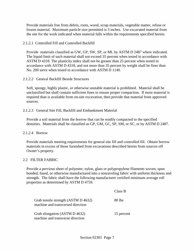
Section 02301 Page 7
Provide materials free from debris, roots, wood, scrap materials, vegetable matter, refuse or frozen material. Maximum particle size permitted is 3 inches. Use excavated material from the site for the work indicated when material falls within the requirements specified herein.
2.1.2.1 Controlled Fill and Controlled Backfill
Provide materials classified as GW, GP, SW, SP, or ML by ASTM D 2487 where indicated. The liquid limit of such material shall not exceed 35 percent when tested in accordance with ASTM D 4318. The plasticity index shall not be greater than 25 percent when tested in accordance with ASTM D 4318, and not more than 35 percent by weight shall be finer than No. 200 sieve when tested in accordance with ASTM D 1140.
2.1.2.2 General Backfill Beside Structures
Soft, spongy, highly plastic, or otherwise unstable material is prohibited. Material shall be unclassified but shall contain sufficient fines to ensure proper compaction. If more material is required than is available from on-site excavation, then provide that material from approved sources.
2.1.2.3 General Site Fill, Backfill and Embankment Material
Provide a soil material from the borrow that can be readily compacted to the specified densities. Materials shall be classified as GP, GM, GC, SP, SM, or SC, or by ASTM D 2487.
2.1.2.4 Borrow
Provide materials meeting requirements for general site fill and controlled fill. Obtain borrow materials in excess of those furnished from excavations described herein from sources off Owner’s property.
2.2 FILTER FABRIC
Provide a pervious sheet of polyester, nylon, glass or polypropylene filaments woven, spun bonded, fused, or otherwise manufactured into a nonraveling fabric with uniform thickness and strength. The fabric shall have the following manufacturer certified minimum average roll properties as determined by ASTM D 4759.
Class B
Grab tensile strength (ASTM D 4632) 80 lbs machine and transversed direction
Grab elongation (ASTM D 4632) 15 percent machine and transverse direction

Section 02301 Page 8
Puncture resistance (ASTM D 4833) 25 lbs
Mullen burst strength (ASTM D 3786) 130 psi
Trapezoidal tear strength (ASTM D 4533) 25 lbs
Apparent opening size (ASTM D 4751) See Criteria Below
Soil with 50 percent or less particles by weight passing US No. 200 Sieve, AOS less than 0.6 mm (greater than No. 30 US Std. Sieve)
Soil with more than 50 percent particles by weight passing US No. 200 Sieve, AOS less than 0.297 mm (greater than No. 50 US Std. Sieve)
Permeability (ASTM D 4491) k fabric greater than k soil
2.3 SUBSURFACE DRAIN PIPE 2.3.1 Polyvinyl Chloride (PVC) Perforated Pipe and Fittings
ASTM F 758 type PS 28 with 3/8 inch maximum diameter holes, 3 1/4 inches on center. Diameter of pipe shall be as shown on the drawings. Make solvent cement joints in accordance with ASTM D 2855. ASTM F 402 for safe handling of solvent cement.
PART 3 EXECUTION 3.1 PROTECTION 3.1.1 Shoring and Sheeting
Provide shoring and sheeting where required. In addition to Section 25 A and B of COE EM-385-1-1, and other requirements of this contract meet the following:
a. Prevent undermining of pavements, foundations and slabs.
b. Slope banks where space permits.
c. Where shoring and sheeting materials remain in place in completed work to prevent
settlements or damage to adjacent structures or as directed, backfill the excavation to 3 feet below the finished grades and remove the remaining exposed portion of the shoring before completing the backfill.
3.1.2 Protection and Restoration of Surfaces

Section 02301 Page 9
Protect newly graded areas from traffic, erosion, and settlements. Repair and reestablish damaged or eroded slopes, elevations or grades and restore surface construction prior to acceptance. Protect existing streams, ditches and storm drain inlets from water-borne soil by means of straw bale dikes. Conduct work in accordance with requirements specified in Section 02000, "Environmental Protection."
3.1.2.1 Disposal of Excavated Material
Dispose of excavated material in such a manner that it will not obstruct the flow of runoff, streams, endanger a partly finished structure, impair the efficiency or appearance of facilities, or be detrimental to the completed work.
3.2 SURFACE PREPARATION 3.2.1 Clearing and Grubbing
Unless indicated otherwise, remove trees, logs, stumps, shrubs, and brush within the limits of construction. Protect from damage trees and shrubs which are to be saved or which are outside the limits of construction. Protect trees which are to be saved during construction by wooden enclosures or wire fences located at or outside of the tree drip lines. Do not permit traffic, parking of equipment, and storage of material within the tree drip lines. Brush, refuse, stumps, roots, and unmerchantable timber shall become the property of the Contractor and removed from the Owner=s property. Conduct work in accordance with requirements specified in Section 02000, "Environmental Protection."
3.2.2 Unsatisfactory Material
Remove organic matter, sod, muck, rubbish, and unsuitable soils under embankments which are less than 3 feet in thickness and under pavements or slabs on grade. Typical depth of removal of such unsuitable material shall be 12 inches.
3.3 EXCAVATION
Excavate to contours and dimensions indicated. Keep excavations free from water while construction is in progress. Notify the Professional immediately in writing in the event that it becomes necessary to remove material defined as unsatisfactory to a depth greater than indicated. Refill excavations cut below the depths indicated with controlled fill and compact as specified herein. Excavate soil disturbed or weakened by construction operations or soils soften from exposure to weather. Refill with controlled fill and compact as specified herein.
3.3.1 Excavations for Structures and Footings
Excavate to depth indicated. If excavation is deeper than indicated, then fill with concrete when the foundations or footings are placed.

Section 02301 Page 10
3.4 BORROW MATERIALS
Select borrow materials to meet requirements and conditions of the particular fill material to be used. Obtain borrow materials from sources off of Owner’s property.
3.5 FILLING AND BACKFILLING 3.5.1 Subgrade Preparation
Scarify the underlying subgrade surface to a depth of 18 inches before the fill is started. Step, bench, or break up sloped surfaces steeper than one vertical to 4 horizontal so that the fill material will bond with or be securely keyed to the existing material. Scarify existing surface to a minimum depth of 18 inches if subgrade density is less than the degree of compaction specified and recompact. When the subgrade is part fill and part excavation or natural ground, scarify the excavated or natural ground portion to a depth of 18 inches and recompact as specified for the adjacent or overlying fill. Compact with equipment well suited to the soil being compacted. Moisten or aerate material as necessary to provide the moisture content that will readily facilitate obtaining the specified compaction with the equipment used.
3.5.2 Fill and Backfill Beside Structures
Place required backfill material adjacent to structures and compact in a manner that prevents wedging action or eccentric loading upon or against the structures. Step or serrate slopes bounding or within areas to be backfilled to prevent sliding of the fill. Moisten or aerate material as necessary to provide the moisture content that will readily facilitate obtaining the specified compaction with the equipment used. Do not place material on surfaces that are muddy, frozen, or contain frost. Do not use equipment for backfilling operations or for the formation of embankments against structures that will overload the structure. Backfilling against concrete will be done only after approval has been obtained from the Professional.
3.5.3 Controlled Fill and Controlled Backfill
Place controlled fill and controlled backfill under footing, concrete slabs not pile supported, and pavements in loose lifts of 8 inches. Do not place material on surfaces that are muddy, frozen, or contain frost. Compact with equipment well suited to the soil being compacted. Moisten or aerate material as necessary to provide the moisture content that will readily facilitate obtaining the specified compaction with the equipment used. Compact each lift as specified herein before placing the overlaying lift. Compaction shall be accomplished continuously over the entire area. Sufficient passes shall be made to ensure that specified density is obtained.
3.5.4 General Fill, and General Backfill
Construct fill, and backfill at the locations and to lines and grades indicated. Use only approved materials in constructing fill on the prepared subgrade. Place satisfactory material in
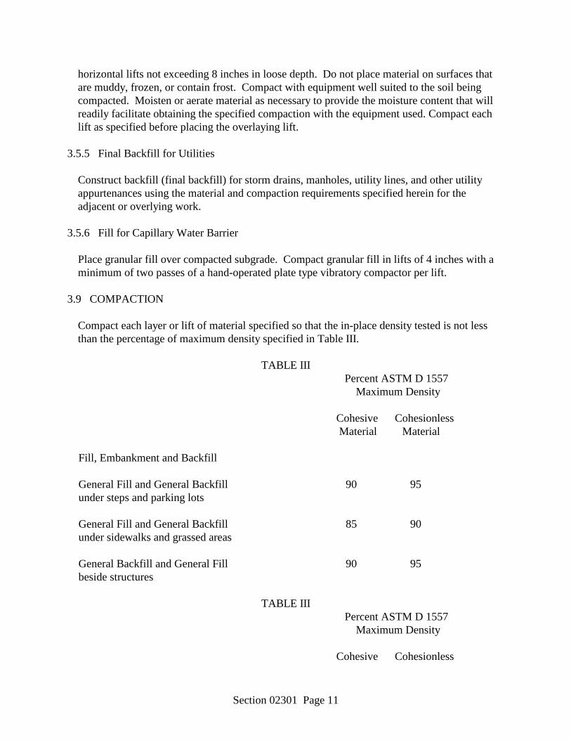
Section 02301 Page 11
horizontal lifts not exceeding 8 inches in loose depth. Do not place material on surfaces that are muddy, frozen, or contain frost. Compact with equipment well suited to the soil being compacted. Moisten or aerate material as necessary to provide the moisture content that will readily facilitate obtaining the specified compaction with the equipment used. Compact each lift as specified before placing the overlaying lift.
3.5.5 Final Backfill for Utilities
Construct backfill (final backfill) for storm drains, manholes, utility lines, and other utility appurtenances using the material and compaction requirements specified herein for the adjacent or overlying work.
3.5.6 Fill for Capillary Water Barrier
Place granular fill over compacted subgrade. Compact granular fill in lifts of 4 inches with a minimum of two passes of a hand-operated plate type vibratory compactor per lift.
3.9 COMPACTION
Compact each layer or lift of material specified so that the in-place density tested is not less than the percentage of maximum density specified in Table III.
TABLE III
Percent ASTM D 1557 Maximum Density Cohesive Cohesionless Material Material Fill, Embankment and Backfill General Fill and General Backfill 90 95 under steps and parking lots General Fill and General Backfill 85 90 under sidewalks and grassed areas General Backfill and General Fill 90 95 beside structures
TABLE III Percent ASTM D 1557 Maximum Density Cohesive Cohesionless
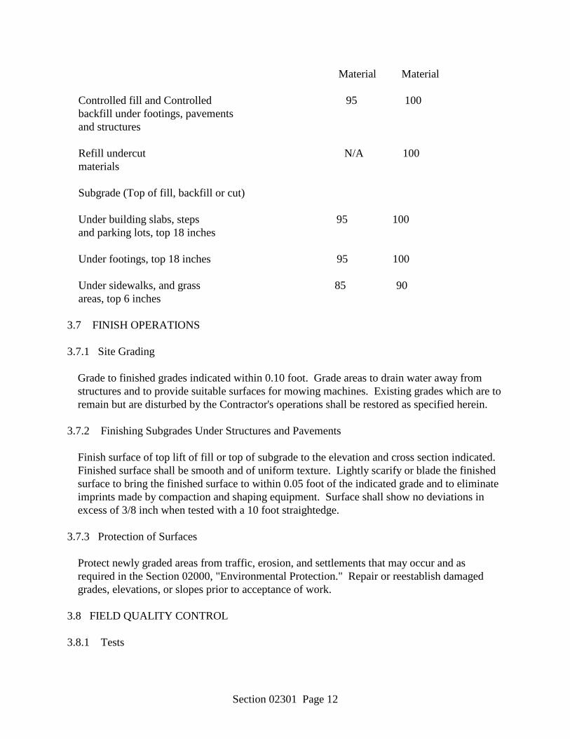
Section 02301 Page 12
Material Material Controlled fill and Controlled 95 100 backfill under footings, pavements and structures Refill undercut N/A 100 materials Subgrade (Top of fill, backfill or cut) Under building slabs, steps 95 100 and parking lots, top 18 inches Under footings, top 18 inches 95 100 Under sidewalks, and grass 85 90 areas, top 6 inches 3.7 FINISH OPERATIONS 3.7.1 Site Grading
Grade to finished grades indicated within 0.10 foot. Grade areas to drain water away from structures and to provide suitable surfaces for mowing machines. Existing grades which are to remain but are disturbed by the Contractor's operations shall be restored as specified herein.
3.7.2 Finishing Subgrades Under Structures and Pavements
Finish surface of top lift of fill or top of subgrade to the elevation and cross section indicated. Finished surface shall be smooth and of uniform texture. Lightly scarify or blade the finished surface to bring the finished surface to within 0.05 foot of the indicated grade and to eliminate imprints made by compaction and shaping equipment. Surface shall show no deviations in excess of 3/8 inch when tested with a 10 foot straightedge.
3.7.3 Protection of Surfaces
Protect newly graded areas from traffic, erosion, and settlements that may occur and as required in the Section 02000, "Environmental Protection." Repair or reestablish damaged grades, elevations, or slopes prior to acceptance of work.
3.8 FIELD QUALITY CONTROL 3.8.1 Tests
Section 02301 Page 13
Test fill, backfill and granular fill using ASTM C 136 for conformance to ASTM C 33, and ASTM D 2487 gradation limits. Test fill for material finer than the No. 200 sieve using ASTM D 1140. Test fill for liquid limit and plasticity index using ASTM D 4318. Test fill and subgrade in cut materials for moisture density relations using ASTM D 1557 or ASTM D 4253 and ASTM D 4254. Test fill for permeability in accordance with ASTM D 2434. Perform one of each of the required tests for each material used when directed. Provide additional tests as specified above for each source change. Perform density tests in randomly selected locations using ASTM D 2922 and ASTM D 3017 as follows: one test per 2,000 square feet in each layer of lift or 250 square yards subgrade in cut. Determine moisture content of soil material in place at every location where in-place density is tested. Where ASTM D 2922 and ASTM D 3017 are used to test field compaction densities, verify the results of the tests by performing at least one test per day using ASTM D 1556 at a location already tested by ASTM D 2922 and at least one additional test using ASTM D 1556 for every 10 tests performed with a nuclear device, also at locations already checked by ASTM D 2922.
3.8.2 Controlled Fill
Method of in-place density tests shall be in accordance with paragraph entitled "Tests." Acceptance of the compacted material shall be determined in each location by the results of a minimum of two consecutive tests. The average of two tests shall equal or exceed the specified density. The location of the tests for each compacted layer will be randomly selected by the Professional.
-- End of Section --

Section 02361 Page 1
SECTION 02361 SOIL TREATMENT FOR SUBTERRANEAN TERMITE CONTROL
PART 1 GENERAL 1.1 REFERENCES
UNITED STATES CODE (USC)
7 USC Section 136 Federal Insecticide, Fungicide, and Rodenticide Act 1.2 SUBMITTALS
Submit the following in accordance with Section 01300, "SUBMITTALS." 1.2.1 Instructions
a. Pesticides
Submit a copy of manufacturer's label and Material Safety Data Sheet (MSDS). 1.2.2 Statements
a. Qualifications of pesticide applicators
Submit data as required in paragraph entitled "Qualifications of Pesticide Applicators," prior to commencement of work.
1.2.3 Samples
a. Pesticides
Submit on request, or the Professional may draw at any time and without prior notice, from stocks at the job site, samples of the pesticides used in this work. Should analysis, performed by the Owner, indicate such samples to contain less than the amount of active ingredient specified on the label, work performed with such products shall be repeated, with pesticides conforming to this specification, at no additional cost to the Owner.
1.2.4 Records
a. Warranty
b. Application report
Submit documents signed by an officer of the Contractor.
Section 02361 Page 2
1.2.4.1 Warranty Requirements
Submit to the Professional as required in paragraph entitled "Warranty." 1.2.4.2 Application Report
Upon completion of this work, submit report identifying brand name and manufacturer of pesticide, dilution, and method and rate of application used.
1.3 QUALIFICATIONS OF PESTICIDE APPLICATORS
The pesticide applicator's principal business shall be pest control and the pesticide applicator shall be State certified in the U.S. Environmental Protection Agency (EPA) pesticide applicator category which includes structural pest control, and certified in the State of operation.
1.4 DELIVERY, STORAGE, AND HANDLING
Deliver pesticides to the project site in sealed and labeled containers in good condition as supplied by the manufacturer or formulator. Store, handle, and use pesticides in accordance with manufacturer's labels. Labels shall bear evidence of registration under the Federal Insecticide, Fungicide, and Rodenticide Act (FIFRA), as amended or appropriate regulations of the host county.
1.5 SAFETY REQUIREMENTS
Formulate, treat, and dispose of termiticides and their containers in accordance with label directions. Draw water for formulating only from sites designated by the Professional, and fit the filling hose with a backflow preventer meeting local plumbing codes or standards. The filling operation shall be under the direct and continuous observation of a contractor's representative to prevent overflow. Secure pesticides and related materials under lock and key when unattended. Ensure that proper protective clothing and equipment are worn and used during all phases of termiticide application. Dispose of used pesticide containers off Owner’s property.
1.6 WARRANTY
Furnish an 5 year written warranty against infestations or reinfestations by subterranean termites of the buildings or building additions constructed under this contract. If live subterranean termite infestation or subterranean termite damage is discovered during the warranty period, and the soil and building conditions have not been altered in the interim, the Contractor shall:
a. Retreat the soil and perform other treatment as may be necessary for elimination of
subterranean termite infestation;
Section 02361 Page 3
b. Repair damage caused by termite infestation; and
c. Reinspect the building approximately 180 days after the retreatment. PART 2 PRODUCTS 2.1 PESTICIDES
Termiticides bearing current registration by the EPA or approved for such use by the appropriate agency.
PART 3 EXECUTION 3.1 VERIFICATION OF CONDITIONS
At the time of application, the soil shall have a sufficiently low moisture content to allow uniform distribution of the treatment solution throughout the soil. Do not make applications during or immediately following heavy rains or when conditions may cause runoff and create an environmental hazard.
3.2 APPLICATION 3.2.1 Treatment Area
Apply termiticide to soil material which will be covered by or lie immediately adjacent to the buildings and structures so as to provide a protective barrier against subterranean termites.
3.2.2 Treatment Application
Apply termiticide as a coarse spray and in such manner as to provide uniform distribution onto the soil surface. Apply treatment prior to placement of a vapor barrier or waterproof membrane and at least 12 hours prior to concrete pouring. Where treated soil or fill material is not to be covered with a vapor barrier or waterproof membrane, exercise adequate precautions to prevent its disturbance. If soil or fill material has been disturbed after treatment, retreat as specified above before placement of slabs or other covering structures. Coordinate treatment of the soil on the exterior sides of foundation walls, grade beams, and similar structures with final grading and planting operations so as to avoid disturbance of the treated barriers by such operations. Observe manufacturer's warnings and precautions in the handling and use of such materials. Exercise precaution that these chemicals do not enter water supply systems or potable water supplies or aquifers, and that they do not endanger plants and animals as well. Notify the Professional at least 48 hours prior to beginning of treatment and perform formulating, mixing, and application in the presence of Professional.
3.2.3 Rates and Methods of Application

Section 02361 Page 4
Apply in accordance with the pesticide label. Provide maximum application or dosage rates. Resolve conflict between this specification and label direction in favor of the label.
-- End of Section --
Section 02539 Page 1
SECTION 02539 SANITARY SEWAGE SYSTEMS
PART 1 GENERAL 1.1 SUMMARY
A Section includes sanitary sewerage drainage piping, fittings, accessories and bedding; connection of building sanitary drainage system to sewer treatment plant and cleanout access.
B Related Sections
1. Section 02225 – Excavation, Backfilling, and Compacting for Utilities. 2. Section 03300 - Cast-in-Place Concrete: Concrete type for cleanout base
pad construction. 1.2 REFERENCES
A AASHTO T180 (American Association of State Highway and Transportation Officials) - Moisture-Density Relations of Soils Using a 10-lb Rammer and an 18-in. Drop.
B ANSI/ASTM A74 - Cast Iron Soil Pipe and Fittings.
C ANSI/ASTM C14 - Concrete Sewer, Storm Drain, and Culvert Pipe.
D ANSI/ASTM C76 - Reinforced Concrete Culvert, Storm Drain, and Sewer Pipe.
E ANSI/ASTM C443 - Joints for Circular Concrete Sewer and Culvert Pipe, Using
Rubber Gaskets.
F ANSI/ASTM D698 - Test Methods for Moisture-Density Relations of Soils and Soil-Aggregate Mixtures, Using 5.5 lb Rammer and 12 inch Drop.
G ANSI/ASTM D1557 - Test Methods for Moisture-Density Relations of Soils and
Soil-Aggregate Mixtures Using 10 lb Rammer and 18 inch Drop.
H ANSI/ASTM D2321 - Recommended Practice for Underground Installation of Flexible Thermoplastic Sewer Pipe.
I ANSI/ASTM D2729 - Poly(Vinyl Chloride) (PVC) Sewer Pipe and Fittings.
J ANSI/ASTM D2751 - Acrylonitrile-Butadiene-Styrene (ABS) Sewer Pipe and
Fittings.
Section 02539 Page 2
K ANSI/ASTM D3033 - Type PSP Poly(Vinyl Chloride) (PVC) Sewer Pipe and Fittings.
L ANSI/ASTM D3034 - Type PSM Poly(Vinyl Chloride) (PVC) Sewer Pipe and
Fittings.
M ASTM A746 - Ductile Iron Gravity Sewer Pipe.
N ASTM C564 - Rubber Gaskets for Cast Iron Soil Pipe and Fittings.
O ASTM D1785 - Poly(Vinyl Chloride) (PVC) Plastic Pipe, Schedules 40, 80 and 120.
P ASTM D2922 - Test Methods for Density of Soil and Soil-Aggregate in Place by
Nuclear Methods (Shallow Depth).
Q ASTM D3017 - Test Methods for Moisture Content of Soil and Soil-Aggregate Mixtures.
1.3 DEFINITIONS
A Bedding: Fill placed under, beside and directly over pipe, prior to subsequent backfill operations.
1.4 SUBMITTALS
A Section 01300 – SUBMITTALS: Submittal procedures.
B Product Data: Submit data indicating pipe, and pipe accessories.
C Manufacturer's Installation Instructions: Indicate special procedures required to install Products specified.
D Manufacturer's Certificate: Certify that products meet or exceed specified
requirements. 1.5 CLOSEOUT SUBMITTALS
A Project Record Documents: Record location of pipe runs, connections, cleanouts, and invert elevations.
1.6 FIELD MEASUREMENTS
A Verify that field measurements and elevations are as indicated.
Section 02539 Page 3
1.7 COORDINATION
A Section 01300 – SUBMITTALS: Submittal procedures.
B Coordinate the Work with termination of sanitary sewer connection outside building, connection to sewer treatment plant, and trenching.
PART 2 PRODUCTS 2.1 SEWER PIPE MATERIALS
A Plastic Pipe: ASTM D1785, Schedule 40, Poly(Vinyl Chloride) (PVC) material; inside nominal diameter of 4 inches, bell and spigot style solvent sealed joint end.
2.2 PIPE ACCESSORIES
A Trace Wire: Magnetic detectable conductor, brightly colored plastic covering, imprinted with "Sewer Service" in large letters.
2.3 CLEANOUTS
A Lid and Frame: Cast iron construction.
B Base Pad: Cast-In-Place concrete with a minimum compressive strength of 2500 psi at 28 days.
PART 3 EXECUTION 3.1 EXAMINATION
A Section 01300 – SUBMITTALS: Submittal procedures.
B Verify that trench cut is ready to receive work and excavations, dimensions, and elevations are as indicated on drawings.
3.2 PREPARATION
A Correct over excavation with lean concrete.
B Remove large stones or other hard matter which could damage pipe or impede consistent backfilling or compaction.
3.3 BEDDING

Section 02539 Page 4
A Place bedding material at trench bottom, level materials in continuous layer not exceeding 6 inches compacted depth, compact to 95 percent of ASTM 698.
B Maintain optimum moisture content of bedding material to attain required
compaction density. 3.4 INSTALLATION - PIPE
A Install pipe, fittings, and accessories in accordance with ASTM D2321. Seal joints watertight.
B Lay pipe to slope gradients noted on drawings; with maximum variation from true
slope of 1/8 inch in 10 feet.
C Refer to drawings for trenching requirements. Do not displace or damage pipe when compacting.
D Connect to building sanitary sewer outlet and sewer treatment plant.
E Install trace wire continuous over top of pipe. Buried 12 inches below finish
grade. 3.5 INSTALLATION - CLEANOUTS
A Form bottom of excavation clean and smooth to correct elevation.
B Form and place Cast-In-place Concrete base pad, with provision for sanitary sewer pipe end sections.
C Establish elevations and pipe inverts for inlets and outlets as indicated.
D Mount lid and frame level in grout, secured to top cone section to elevation
indicated. 3.6 FIELD QUALITY CONTROL
A Request inspection prior to placing bedding.
B Compaction testing will be performed in accordance with ANSI/ASTM D698.
C If tests indicate Work does not meet specified requirements, remove Work, replace and retest at no cost to Owner.
D Frequency of Tests: 1 test/200 foot of trench.
Section 02539 Page 5
E Pressure Test: Test in accordance with state of Mississippi Department of Environmental Quality.
F Infiltration Test: Test in accordance with state of Mississippi Department of
Environmental Quality. 3.7 PROTECTION OF FINISHED INSTALLATION
A Protect pipe and aggregate cover from damage or displacement until backfilling operation is in progress.
-- End of Section --

Section 02753 Page 1
SECTION 02753 PORTLAND CEMENT CONCRETE PAVEMENT
PART 1 GENERAL 1.1 SUMMARY
A Section includes concrete sidewalks, gutters, parking areas, and roads; and aggregate base course.
1.2 REFERENCES
A ACI 301 (American Concrete Institute) - Specifications for Structural Concrete for Buildings.
B ACI 304 (American Concrete Institute) - Recommended Practice for Measuring,
Mixing, Transporting and Placing Concrete.
C ASTM A185 - Welded Steel Wire Fabric for Concrete Reinforcement.
D ASTM A497 - Welded Deformed Steel Wire Fabric for Concrete Reinforcement.
E ASTM A615 - Deformed and Plain Billet-Steel for Concrete Reinforcement.
F ASTM C33 - Concrete Aggregates.
G ASTM C94 - Ready Mix Concrete.
H ASTM C150 - Portland Cement
I ASTM C260 - Air-Entraining Admixtures for Concrete.
J ASTM C309 - Liquid Membrane-Forming Compounds for Curing Concrete.
K ASTM C494 - Chemical Admixtures for Concrete.
L ASTM D1751 - Preformed Expansion Joint Fillers for Concrete Paving and Structural Construction.
M ASTM D1752 - Preformed Sponge Rubber and Cork Expansion Joint Fillers for
Concrete Paving and Structural Construction. 1.3 SUBMITTALS
A Section 01300 – SUBMITTALS: Submittal procedures.
Section 02753 Page 2
B Product Data: Submit data on joint filler and curing compounds.
1.4 QUALITY ASSURANCE
A Perform Work in accordance with ACI 301.
B Maintain one copy of each document on site.
C Obtain cementitious materials from same source throughout. 1.5 ENVIRONMENTAL REQUIREMENTS
A Do not place concrete when base surface temperature is less than 40 degrees F, or surface is wet or frozen.
PART 2 PRODUCTS 2.1 FORM MATERIALS
A Form Materials: Conform to ACI 301.
****** OR ******
B Wood or steel form material, profiled to suit conditions.
C Joint Filler: ASTM D1751 type. 2.2 REINFORCEMENT
A Welded Steel Wire Fabric: Plain type, ASTM A185 or Deformed type, A497; in flat sheets; unfinished finish.
2.3 CONCRETE MATERIALS
A Concrete Materials: Provide in accordance with State of Mississippi DOT.
****** OR ******
B Cement: ASTM C150 Normal - Type I or Air Entraining - Type IA, Type V Portland type, gray color.
C Fine and Coarse Mix Aggregates: ASTM C33.
D Water: Potable, not detrimental to concrete.

Section 02753 Page 3
E Air Entrainment: ASTM C260.
2.4 ACCESSORIES
A Curing Compound: ASTM C309, Type 1D.
B Joint Sealers: ASTM D1850. 2.5 CONCRETE MIX - BY PERFORMANCE CRITERIA
A Mix concrete in accordance with ACI 304. Deliver concrete in accordance with ASTM C94.
B Select proportions for normal weight concrete in accordance with ACI 301
Method 1.
C Provide concrete to the following criteria: 1. Compressive Strength: 3,000 psi @ 7 days. 2. Compressive Strength: 4,000 psi @ 28 days. 3. Slump: 2 to 5 inches. 4. Minimum Water/Cement Ratio: 0.49 5. Air Entrained: 6 percent. 6. Minimum Flexural Strength of 375 psi.
D Use accelerating admixtures in cold weather only when approved by the
Architect/Engineer in writing. Use of admixtures will not relax cold weather placement requirements.
E Use calcium chloride only when approved by the Architect/Engineer in writing.
F Use set retarding admixtures during hot weather only when approved by the
Architect/Engineer in writing. 2.6 SOURCE QUALITY CONTROL AND TESTS
A Submit proposed mix design of each class of concrete to appointed firm for review prior to commencement of Work.
B Tests on cement, aggregates, and mixes will be performed to ensure conformance
with specified requirements.
C Test samples in accordance with ACI 301.
Section 02753 Page 4
PART 3 EXECUTION 3.1 EXAMINATION
A Section 01300 – SUBMITTALS.
B Verify compacted engineered fill is acceptable and ready to support paving and imposed loads.
C Verify gradients and elevations of base are correct.
3.2 SUBBASE
A Prepare subbase in accordance with detail on the drawings. 3.3 PREPARATION
A Moisten base to minimize absorption of water from fresh concrete.
B Notify Architect/Engineer minimum 24 hours prior to commencement of concreting operations.
3.4 FORMING
A Place and secure forms to correct location, dimension, profile, and gradient.
B Assemble formwork to permit easy stripping and dismantling without damaging concrete.
C Place joint filler vertical in position, in straight lines. Secure to formwork during
concrete placement. 3.5 REINFORCEMENT
A Place reinforcement as indicated.
B Interrupt reinforcement at contraction joints. 3.6 PLACING CONCRETE
A Coordinate installation of snow melting components.
B Place concrete in accordance with ACI 301.
C Place concrete using the slip form technique.
Section 02753 Page 5
D Ensure reinforcement, inserts, embedded parts, formed joints are not disturbed
during concrete placement.
E Place concrete continuously over the full width of the panel and between predetermined construction joints. Do not break or interrupt successive pours such that cold joints occur.
3.7 JOINTS
A Place expansion joints at 80 foot intervals. Align curb, gutter, and sidewalk joints.
B Place joint filler between paving components and building or other appurtenances.
C Provide keyed joints as indicated.
3.8 FINISHING
A Paving: Light broom.
B Sidewalk Paving: Light broom.
C Curbs and Gutters: Light broom.
D Direction of Texturing: Parallel to pavement direction.
E Place curing compound on exposed concrete surfaces immediately after finishing. 3.9 TOLERANCES
A Maximum Variation of Surface Flatness: 1/4 inch in 10 ft.
B Maximum Variation From True Position: 1/2 inch. 3.10 FIELD QUALITY CONTROL
A Three concrete test cylinders will be taken for every 100 or less cu yds of each class of concrete placed each day.
B One additional test cylinder will be taken during cold weather and cured on site
under same conditions as concrete it represents.
C One slump test will be taken for each set of test cylinders taken.
Section 02753 Page 6
D Maintain records of placed concrete items. Record date, location of pour, quantity, air temperature, and test samples taken.
3.11 PROTECTION
A Immediately after placement, protect pavement from premature drying, excessive hot or cold temperatures, and mechanical injury.
B Do not permit vehicular traffic over pavement until 75 percent design strength of
concrete has been achieved. 3.12 SCHEDULES
A Concrete Sidewalks: 3,000 psi 28 day concrete.
B Parking Area Pavement: 4,000 psi 28 day concrete.
-- End of Section --
Section 03300 Page 1
SECTION 03300 CAST-IN-PLACE CONCRETE
PART 1 GENERAL 1.1 REFERENCES
The publications listed below form a part of this specification to the extent referenced. The publications are referred to in the text by the basic designation only.
AMERICAN ASSOCIATION OF STATE HIGHWAY AND TRANSPORTATION OFFICIALS (AASHTO)
AASHTO M182 (1991) Burlap Cloth Made from Jute or Kenaf
AMERICAN CONCRETE INSTITUTE (ACI)
ACI 117 (1990) Tolerances for Concrete Construction and
Materials
ACI 211.1 (1991) Selecting Proportions for Normal, Heavyweight, and Mass Concrete
ACI 301 (1996) Structural Concrete for Buildings
ACI 302.1R (1996) Concrete Floor and Slab Construction
ACI 304R (1989) Measuring, Mixing, Transporting, and Placing
Concrete
ACI 304.2R (1996) Placing Concrete by Pumping Methods
ACI 305R (1991) Hot Weather Concreting
ACI 306.1 (1990) Cold Weather Concreting
ACI 315 (1994) Details and Detailing of Concrete Reinforcement
ACI 318/318M (1995) Building Code Requirements for Structural Concrete
ACI 347R (1994) Formwork for Concrete
AMERICAN HARDBOARD ASSOCIATION (AHA)
AHA A135.4 (1995) Basic Hardboard
Section 03300 Page 2
AMERICAN SOCIETY FOR TESTING AND MATERIALS (ASTM)
ASTM A 82 (1997) Steel Wire, Plain, for Concrete Reinforcement
ASTM A 185 (1997) Steel Welded Wire Fabric, Plain, for Concrete
Reinforcement
ASTM A 496 (1997) Steel Wire, Deformed, for Concrete Reinforcement
ASTM A 497 (1997) Steel Welded Wire Fabric, Deformed, for
Concrete Reinforcement
ASTM A 615/A 615M (1996; Rev. A) Deformed and Plain Billet-Steel Bars for Concrete Reinforcement
ASTM A 617/A 617M (1996; Rev. A) Axle-Steel Deformed and Plain Bars for
Concrete Reinforcement
ASTM C 31/C 31M (1996) Making and Curing Concrete Test Specimens in the Field
ASTM C 33 (1997) Concrete Aggregates
ASTM C 39 (1996) Compressive Strength of Cylindrical Concrete
Specimens
ASTM C 42 (1994) Obtaining and Testing Drilled Cores and Sawed Beams of Concrete
ASTM C 94 (1997) Ready-Mixed Concrete
ASTM C 143 (1990; Rev. A) Slump of Hydraulic Cement Concrete
ASTM C 150 (1997) Portland Cement
ASTM C 171 (1997) Sheet Materials for Curing Concrete
ASTM C 172 (1997) Sampling Freshly Mixed Concrete
ASTM C 173 (1994; Rev. A) Air Content of Freshly Mixed Concrete
by the Volumetric Method
ASTM C 227 (1990) Potential Alkali Reactivity of Cement-Aggregate Combinations (Mortar-Bar Method)

Section 03300 Page 3
ASTM C 231 (1997) Air Content of Freshly Mixed Concrete by the
Pressure Method
ASTM C 260 (1995) Air-Entraining Admixtures for Concrete
ASTM C 295 (1990) Petrographic Examination of Aggregates for Concrete
ASTM C 309 (1997) Liquid Membrane-Forming Compounds for
Curing Concrete
ASTM C 494 (1992) Chemical Admixtures for Concrete
ASTM C 618 (1997) Coal Fly Ash and Raw or Calcined Natural Pozzolan for Use as a Mineral Admixture in Portland Cement Concrete
ASTM C 881 (1990) Epoxy-Resin-Base Bonding Systems for
Concrete
ASTM C 920 (1995) Elastomeric Joint Sealants
ASTM C 989 (1997) Ground Granulated Blast-Furnace Slag for Use in Concrete and Mortars
ASTM C 1017 (1992) Chemical Admixtures for Use in Producing
Flowing Concrete
ASTM C 1107 (1997) Packaged Dry, Hydraulic-Cement Grout (Nonshrink)
ASTM D 1190 (1996) Concrete Joint Sealer, Hot-Applied Elastic Type
ASTM D 1751 (1983; R 1991) Preformed Expansion Joint Filler for
Concrete Paving and Structural Construction (Nonextruding and Resilient Bituminous Types)
ASTM D 1752 (1984; R 1996) Preformed Sponge Rubber and Cork
Expansion Joint Fillers for Concrete Paving and Structural Construction
ASTM D 4397 (1996) Polyethylene Sheeting for Construction,
Industrial, and Agricultural Applications
Section 03300 Page 4
AMERICAN WELDING SOCIETY, INC. (AWS)
AWS D1.4 (1998) Structural Welding Code Reinforcing Steel
CORPS OF ENGINEERS (COE)
COE CRD-C-572 (1974) Polyvinylchloride Waterstop
U.S. DEPARTMENT OF COMMERCE PRODUCT STANDARDS (PS)
PS-1 (1995) Construction and Industrial Plywood
FEDERAL SPECIFICATIONS (FS)
FS UU-B-790 (Rev. A Reinst) Building Paper, Vegetable Fiber: (Kraft, Waterproofed, Water Repellent and Fire Resistant)
1.2 DEFINITIONS
a. "Cementitious material" as used herein shall include all portland cement, pozzolan, fly ash, and ground iron blast-furnace slag.
b. "Exposed to public view" means situated so that it can be seen from eye level from a
public location after completion of the building. A public location is accessible to persons not responsible for operation or maintenance of the building.
1.3 SUBMITTALS
Submit the following in accordance with Section 01300, "Submittals." 1.3.1 Data
a. Calculations 1.3.1.1 Formwork Calculations
ACI 347R. Include design calculations indicating arrangement of forms, sizes and grades of supports (lumber), panels, and related components. Furnish drawings and calculations of shoring and reshoring methods proposed for floor and roof slabs, spandrel beams, and other horizontal concrete members.
1.3.2 Manufacturer's Catalog Data
a. Materials for curing concrete

Section 03300 Page 5
b. Joint sealants
c. Joint filler
d. Vapor barrier
e. Epoxy bonding compound
f. Waterstops 1.3.3 Drawings
a. Formwork
b. Reinforcing steel
Reproductions of contract drawings are unacceptable. 1.3.3.1 Formwork
Drawings showing details of formwork including; joints, supports, studding and shoring, and sequence of form and shoring removal. Reproductions of contract drawings are unacceptable.
1.3.3.2 Reinforcing Steel
ACI 315. Indicate bending diagrams, assembly diagrams, splicing and laps of bars, shapes, dimensions, and details of bar reinforcing, accessories, and concrete cover. Do not scale dimensions from structural drawings to determine lengths of reinforcing bars.
1.3.4 Statements
a. Curing concrete elements
b. Pumping concrete 1.3.4.1 Curing Concrete Elements
Submit proposed materials and methods for curing concrete elements. 1.3.4.2 Pumping Concrete
Submit proposed materials and methods for pumping concrete. Submittal shall include mix designs, pumping equipment including type of pump and size and material for pipe, and maximum length and height concrete will be pumped.
Section 03300 Page 6
1.3.5 Test Reports
a. Concrete mix design
b. Fly ash
c. Pozzolan
d. Ground iron blast-furnace slag
e. Aggregates 1.3.5.1 Concrete Mix Design
Submit copies of laboratory test reports showing that the mix has been successfully tested to produce concrete with the properties specified and that mix will be suitable for the job conditions. The laboratory test reports shall include mill test and all other test for cement, aggregates, and admixtures. Provide maximum nominal aggregate size, gradation analysis, percentage retained and passing sieve, and a graph of percentage retained verses sieve size. Test reports shall be submitted along with the concrete mix design. Obtain approval before concrete placement.
1.3.5.2 Fly Ash and Pozzolan
Submit test results in accordance with ASTM C 618 for fly ash and pozzolan. Submit test results performed within 6 months of submittal date.
1.3.5.3 Ground Iron Blast-Furnace Slag
Submit test results in accordance with ASTM C 989 for ground iron blast-furnace slag. Submit test results performed within 6 months of submittal date.
1.3.5.4 Aggregates
ASTM C 227 for potential alkali-silica reactions, ASTM C 295 for petrographic analysis. 1.3.6 Field Test Reports
a. Compressive strength tests 1.4 MODIFICATION OF REFERENCES
Accomplish work in accordance with ACI publications except as modified herein. Consider the advisory or recommended provisions to be mandatory, as though the word "shall" had been substituted for the words "should" or "could" or "may," wherever they appear. Interpret
Section 03300 Page 7
reference to the "Building Official," the "Structural Engineer," and the "Architect/Engineer" to mean the Professional
1.5 DELIVERY, STORAGE, AND HANDLING
Do not deliver concrete until vapor barrier, forms, reinforcement, embedded items, and chamfer strips are in place and ready for concrete placement. ACI 301 for job site storage of materials. Protect materials from contaminants such as grease, oil, and dirt. Ensure materials can be accurately identified after bundles are broken and tags removed.
1.5.1 Reinforcement
Store reinforcement of different sizes and shapes in separate piles or racks raised above the ground to avoid excessive rusting. Protect from contaminants such as grease, oil, and dirt. Ensure bar sizes can be accurately identified after bundles are broken and tags removed.
PART 2 PRODUCTS 2.1 MATERIALS FOR FORMS
Provide wood, plywood, or steel. Use plywood or steel forms where a smooth form finish is required. Lumber shall be square edged or tongue-and-groove boards, free of raised grain, knotholes, or other surface defects. Plywood: PS-1, B-B concrete form panels or better or AHA A135.4, hardboard for smooth form lining. Steel form surfaces shall not contain irregularities, dents, or sags.
2.2 FORM TIES AND ACCESSORIES
The use of wire alone is prohibited. Form ties and accessories shall not reduce the effective cover of the reinforcement.
2.2.1 Water Stops 2.2.1.1 Polyvinylchloride Waterstops
COE CRD-C-572. 2.2.1.2 Hydrophillic Water Stops
Hydrophillic water stop similar or equal to Hydrotite as manufactured by Greenstreak, Inc. 2.3 CONCRETE 2.3.1 Contractor-Furnished Mix Design

Section 03300 Page 8
ACI 211.1, ACI 301, and ACI 318/318M and ACI 304.2R except as otherwise specified. The compressive strength (f'c) of the concrete for each portion of the structure(s) shall be as indicated and as specified below.
f'c ASTM C 33 Maximum (Min. 28- Maximum Range Water- Day Comp. Nominal of Cement Air Strength) Aggregate Slump Ratio Entr. Location (psi) (Size No.) (inches) (by weight) (percent) Concrete exposed to weather 4000 67 3-4 0.50 5-7 Reinforced foundation walls and footings 4000 57 1-3 0.50 3-4 Beams and reinforced walls 4000 67 1-4 0.50 3-4 Building columns 4000 67 1-4 Pavement and exterior slabs 3000 57 1-3 0.50 5-7 Floor slabs 4000 67 1-3 0.50 3-4 Floor toppings (other than terrazzo 5000 8 5-7 0.50 3-6 Walks 3000 57 1-4 0.50 3-7 Utility structures 5000 7 1-4 0.45 3-7 Drainage structures 3000 57 1-4 0.50 5-7 f'c ASTM C 33 Maximum (Min. 28- Maximum Range Water- Day Comp. Nominal of Cement Air
Section 03300 Page 9
Strength) Aggregate Slump Ratio Entr. Location (psi) (Size No.) (inches) (by weight) (percent) Pumped elevated concrete 4000 67 4-6 0.50
Maximum slump shown above may be increased one inch for methods of consolidation other than vibration. Slump may be increased to 8 inches when superplasticizers are used. Provide air entrainment using air-entraining admixture. Air entrainment shall be within plus or minus 1.5 percent of the valve specified.
2.3.1.1 Required Average Strength of Mix Design
The selected mixture shall produce an average compressive strength exceeding the specified strength by the amount indicated in ACI 301. When a concrete production facility has a record of at least 15 consecutive tests, the standard deviation shall be calculated and the required average compressive strength shall be determined in accordance with ACI 301. When a concrete production facility does not have a suitable record of tests to establish a standard deviation, the required average strength shall be as follows:
a. For f'c less than 3000 psi, 1000 psi plus f'c.
b. For f'c between 3000 and 5000 psi, 1200 psi plus f'c.
c. For f'c over 5000 psi, 1400 psi plus f'c.
2.4 MATERIALS 2.4.1 Cement
ASTM C 150, Type I or II blended cement except as modified herein. The blended cement shall consist of a mixture of ASTM C 150, Type II, cement and one of the following materials: ASTM C 618 pozzolan or fly ash, ASTM C 989 ground iron blast-furnace slag. The pozzolan or fly ash content shall not exceed 25 percent by weight of the total cementitious material. The ground iron blast-furnace slag shall not exceed 50 percent by weight of total cementitious material. For exposed concrete, use one manufacturer for each type of cement, ground slag, fly ash, and pozzolan.
2.4.1.1 Fly Ash and Pozzolan
ASTM C 618, Type N, F, or C, except that the maximum allowable loss on ignition shall be 6 percent for Types N and F. Add with cement.
2.4.1.2 Ground Iron Blast-Furnace Slag
ASTM C 989, Grade 120.
Section 03300 Page 10
2.4.2 Water
Water shall be fresh, clean, and potable; free from injurious amounts of oils, acids, alkalis, salts, organic materials, or other substances deleterious to concrete.
2.4.3 Aggregates
ASTM C 33, except as modified herein. Furnish aggregates for exposed concrete surfaces from one source. Aggregates shall not contain any substance which may be deleteriously reactive with the alkalies in the cement.
2.4.4 Nonshrink Grout
ASTM C 1107. 2.4.5 Admixtures
ASTM C 494: Type A, water reducing; Type B, retarding; Type C, accelerating; Type D, water-reducing and retarding; and Type E, water-reducing and accelerating admixture. Do not use calcium chloride admixtures.
2.4.5.1 Air-Entraining
ASTM C 260. 2.4.5.2 High Range Water Reducer (HRWR) (Superplasticizers)
ASTM C 494, Type F and Type G (HRWR retarding admixture) and ASTM C 1017. 2.4.6 Vapor Barrier
ASTM D 4397 polyethylene sheeting, minimum 10 mil thickness. 2.4.6.1 Waterproof Paper
Kraft paper, glass reinforcing fibers and layers of polyethylene laminated under heat and pressure to form a single layer meeting the requirements of FS UU-B-790, Type I, Grade A, Style 4; or waterproof paper, regular, conforming to ASTM C 171, consisting of two sheets of kraft paper cemented together with bituminous material in which are embedded cords or strands of fiber running in both directions not more than 1 1/4 inch apart.
2.4.7 Materials for Curing Concrete 2.4.7.1 Impervious Sheeting
Section 03300 Page 11
ASTM C 171; waterproof paper, clear or white polyethylene sheeting, or polyethylene-coated burlap.
2.4.7.2 Pervious Sheeting
AASHTO M182. 2.4.7.3 Liquid Membrane-Forming Compound
ASTM C 309, white-pigmented, Type 2, Class B. 2.4.8 Liquid Chemical Sealer-Hardener Compound
Compound shall be magnesium fluosilicate which when mixed with water seals and hardens the surface of the concrete. Do not use on exterior slabs exposed to freezing conditions. Compound shall not reduce the adhesion of resilient flooring, tile, paint, roofing, waterproofing, or other material applied to concrete.
2.4.9 Expansion/Contraction Joint Filler
ASTM D 1751 or ASTM D 1752, 1/2 inch thick, unless otherwise indicated. 2.4.10 Joint Sealants 2.4.10.1 Horizontal Surfaces, 3 Percent Slope, Maximum
ASTM D 1190 or ASTM C 920, Type M, Class 25, Use T. 2.4.10.2 Vertical Surfaces Greater Than 3 Percent Slope
ASTM C 920, Type M, Grade NS, Class 25, Use T. 2.4.11 Epoxy Bonding Compound
ASTM C 881. Provide Type I for bonding hardened concrete to hardened concrete; Type II for bonding freshly mixed concrete to hardened concrete; and Type III as a binder in epoxy mortar or concrete, or for use in bonding skid-resistant materials to hardened concrete. Provide Grade 1 or 2 for horizontal surfaces and Grade 3 for vertical surfaces. Provide Class A if placement temperature is below 40 degrees F; Class B if placement temperature is between 40 and 60 degrees F; or Class C if placement temperature is above 60 degrees F.
2.5 REINFORCEMENT 2.5.1 Reinforcing Bars
Section 03300 Page 12
ACI 301 unless otherwise specified. ASTM A 615/A 615M and ASTM A 617/A 617M with the bars marked A, S, W, Grade 60.
2.5.2 Mechanical Reinforcing Bar Connectors
ACI 301. Provide 125 percent minimum yield strength of the reinforcement bar. 2.5.3 Welded Wire Fabric
ASTM A 185 or ASTM A 497. Provide flat sheets of welded wire fabric for slabs and toppings.
2.5.4 Wire
ASTM A 82 or ASTM A 496. 2.5.5 Reinforcing Bar Supports
Provide bar ties and supports of coated or non corrodible material. PART 3 EXECUTION 3.1 FORMS
ACI 301. Provide forms, shoring, and scaffolding for concrete placement. Set forms mortar-tight and true to line and grade. Chamfer above grade exposed joints, edges, and external corners of concrete 0.75 inch unless otherwise indicated. Provide formwork with clean-out openings to permit inspection and removal of debris. Forms submerged in water shall be watertight.
3.1.1 Coating
Before concrete placement, coat the contact surfaces of forms with a nonstaining mineral oil, nonstaining form coating compound, or two coats of nitrocellulose lacquer. Do not use mineral oil on forms for surfaces to which adhesive, paint, or other finish material is to be applied.
3.1.2 Removal of Forms and Supports
After placing concrete, forms shall remain in place for the time periods specified in ACI 347R. Prevent concrete damage during form removal.
3.1.2.1 Special Requirements for Reduced Time Period

Section 03300 Page 13
Forms may be removed earlier than specified if ASTM C 39 test results of field-cured samples from a representative portion of the structure indicate that the concrete has reached a minimum of 85 percent of the design strength.
3.1.3 Reshoring
Reshore concrete elements where forms are removed prior to the specified time period. Do not permit elements to deflect or accept loads during form stripping or reshoring. Forms on columns, walls, or other load-bearing members may be stripped after 2 days if loads are not applied to the members. After forms are removed, slabs and beams over 10 feet in span and cantilevers over 4 feet shall be reshored for the remainder of the specified time period in accordance with paragraph entitled "Removal of Forms." Perform reshoring operations to prevent subjecting concrete members to overloads, eccentric loading, or reverse bending. Reshoring elements shall have the same load-carrying capabilities as original shoring and shall be spaced similar to original shoring. Firmly secure and brace reshoring elements to provide solid bearing and support.
3.2 Waterstop Splices
Fusion weld in the field. 3.3 Formed Surfaces 3.3.1 Tolerances
ACI 347R and as indicated. 3.3.2 As-Cast Form
Provide form facing material producing a smooth, hard, uniform texture on the concrete. Arrange facing material in an orderly and symmetrical manner and keep seams to a practical minimum. Support forms as necessary to meet required tolerances. Material with raised grain, torn surfaces, worn edges, patches, dents, or other defects which will impair the texture of the concrete surface shall not be used.
3.4 PLACING REINFORCEMENT AND MISCELLANEOUS MATERIALS
ACI 301. Provide bars, wire fabric, wire ties, supports, and other devices necessary to install and secure reinforcement. Reinforcement shall not have rust, scale, oil, grease, clay, or foreign substances that would reduce the bond. Rusting of reinforcement is a basis of rejection if the effective cross-sectional area or the nominal weight per unit length has been reduced. Remove loose rust prior to placing steel. Tack welding is prohibited.
3.4.1 Vapor Barrier

Section 03300 Page 14
Provide beneath the on-grade concrete floor slab. Use the greatest widths and lengths practicable to eliminate joints wherever possible. Lap joints a minimum of 12 inches and tape or cement joints. Remove torn, punctured, or damaged vapor barrier material and provide with new vapor barrier prior to placing concrete. Concrete placement shall not damage vapor barrier material.
3.4.2 Reinforcement Supports
Place reinforcement and secure with galvanized or non corrodible chairs, spacers, or metal hangers. For supporting reinforcement on the ground, use concrete or other non corrodible material, having a compressive strength equal to or greater than the concrete being placed.
3.4.3 Splicing
As indicated. For splices not indicated ACI 301. Do not splice at points of maximum stress. Overlap welded wire fabric the spacing of the cross wires, plus 2 inches. AWS D1.4. Welded splices shall be approved prior to use.
3.4.4 Future Bonding
Plug exposed, threaded, mechanical reinforcement bar connectors with a greased bolt. Bolt threads shall match the connector. Countersink the connector in the concrete. Calk the depression after the bolt is installed.
3.4.5 Cover
ACI 301 for minimum coverage, unless otherwise indicated. 3.4.6 Setting Miscellaneous Material
Place and secure anchors and bolts, pipe sleeves, conduits, and other such items in position before concrete placement. Plumb anchor bolts and check location and elevation. Temporarily fill voids in sleeves with readily removable material to prevent the entry of concrete.
3.4.7 Construction Joints
Locate joints to least impair strength. Continue reinforcement across joints unless otherwise indicated.
3.4.8 Expansion Joints and Contraction Joints
Provide expansion joint at edges of interior floor slabs on grade abutting vertical surfaces, and as indicated. Make expansion joints 1/2 inch wide unless indicated otherwise. Fill expansion joints not exposed to weather with preformed joint filler material. Completely fill joints exposed to weather with joint filler material and joint sealant. Do not extend reinforcement or

Section 03300 Page 15
other embedded metal items bonded to the concrete through any expansion joint unless an expansion sleeve is used. Provide contraction joints, either formed or saw cut or cut with a jointing tool, to the indicated depth after the surface has been finished. Sawed joints shall be completed within 4 to 12 hours after concrete placement. Protect joints from intrusion of foreign matter.
3.5 BATCHING, MEASURING, MIXING, AND TRANSPORTING CONCRETE
ASTM C 94, ACI 301, ACI 302.1R, and ACI 304R, except as modified herein. Batching equipment shall be such that the concrete ingredients are consistently measured within the following tolerances: 1 percent for cement and water, 2 percent for aggregate, and 3 percent for admixtures. Furnish mandatory batch ticket information for each load of ready mix concrete.
3.5.1 Measuring
Make measurements at intervals as specified in paragraphs entitled "Sampling" and "Testing." 3.5.2 Mixing
ASTM C 94 and ACI 301. Machine mix concrete. Begin mixing within 30 minutes after the cement has been added to the aggregates. Reduce mixing time and place concrete within 60 minutes if the air temperature is greater than 85 degrees F except as follows: if set retarding admixture is used and slump requirements can be met, limit for placing concrete may remain at 90 minutes. Additional water may be added, provided that both the specified maximum slump and water-cement ratio are not exceeded. When additional water is added, an additional 30 revolutions of the mixer at mixing speed is required. If the entrained air content falls below the specified limit, add a sufficient quantity of admixture to bring the entrained air content within the specified limits. Dissolve admixtures in the mixing water and mix in the drum to uniformly distribute the admixture throughout the batch.
3.5.3 Transporting
Transport concrete from the mixer to the forms as rapidly as practicable. Prevent segregation or loss of ingredients. Clean transporting equipment thoroughly before each batch. Do not use aluminum pipe or chutes. Remove concrete which has segregated in transporting and dispose of as directed.
3.6 PLACING CONCRETE
Place concrete as soon as practicable after the forms and the reinforcement have been inspected and approved. Do not place concrete when weather conditions prevent proper placement and consolidation; in uncovered areas during periods of precipitation; or in standing water. Prior to placing concrete, remove dirt, construction debris, water, snow, and ice from within the forms. Deposit concrete as close as practicable to the final position in the forms. Do not exceed a free vertical drop of 3 feet from the point of discharge. Place concrete in one
Section 03300 Page 16
continuous operation from one end of the structure towards the other. Position grade stakes on 10 foot centers maximum in each direction when pouring interior slabs and on 20 foot centers maximum for exterior slabs.
3.6.1 Footing Placement
Concrete for footings may be placed in excavations without forms upon inspection and approval by the Professional. Excavation width shall be a minimum of 4 inches greater than indicated.
3.6.2 Vibration
ACI 301. Furnish a spare vibrator on the job site whenever concrete is placed. Consolidate concrete slabs greater than 4 inches in depth with high frequency, internal, mechanical vibrating equipment supplemented by hand spading and tamping. Consolidate concrete slabs 4 inches or less in depth by wood tampers, spading, and settling with a heavy leveling straightedge. Operate vibrators with vibratory element submerged in the concrete, with a minimum frequency of not less than 6000 impulses per minute when submerged. Do not use vibrators to transport the concrete in the forms. Insert and withdraw vibrators approximately 18 inches apart. Penetrate the previously placed lift with the vibrator when more than one lift is required. Place concrete in 18 inch maximum vertical lifts. External vibrators shall be used on the exterior surface of the forms when internal vibrators do not provide adequate consolidation of the concrete.
3.6.3 Application of Epoxy Bonding Compound
Apply a thin coat of compound to dry, clean surfaces. Scrub compound into the surface with a stiff-bristle brush. Place concrete while compound is stringy. Do not permit compound to harden prior to concrete placement. Follow manufacturer's instructions regarding safety and health precautions when working with epoxy resins.
3.6.4 Pumping
ACI 304R and ACI 304.2R. Pumping shall not result in separation or loss of materials nor cause interruptions sufficient to permit loss of plasticity between successive increments. Loss of slump in pumping equipment shall not exceed 2 inches. Concrete shall not be conveyed through pipe made of aluminum or aluminum alloy. Rapid changes in pipe sizes shall be avoided. Maximum size of course aggregate shall be limited to 33 percent of the diameter of the pipe. Maximum size of well rounded aggregate shall be limited to 40 percent of the pipe diameter. Samples for testing shall be taken at both the point of delivery to the pump and at the discharge end.
3.6.5 Cold Weather
ACI 306.1. Do not allow concrete temperature to decrease below 50 degrees F. Obtain approval prior to placing concrete when the ambient temperature is below 40 degrees F or
Section 03300 Page 17
when concrete is likely to be subjected to freezing temperatures within 24 hours. Cover concrete and provide sufficient heat to maintain 50 degrees F minimum adjacent to both the formwork and the structure while curing. Limit the rate of cooling to 5 degrees F in any 1 hour and 50 degrees F per 24 hours after heat application.
3.6.6 Hot Weather
ACI 305R. Maintain required concrete temperature using Figure 2.1.5 in ACI 305R to prevent the evaporation rate from exceeding 0.2 pound of water per square foot of exposed concrete per hour. Cool ingredients before mixing or use other suitable means to control concrete temperature and prevent rapid drying of newly placed concrete. Shade the fresh concrete as soon as possible after placing. Start curing when the surface of the fresh concrete is sufficiently hard to permit curing without damage. Provide water hoses, pipes, spraying equipment, and water hauling equipment, where job site is remote to water source, to maintain a moist concrete surface throughout the curing period. Provide burlap cover or other suitable, permeable material with fog spray or continuous wetting of the concrete when weather conditions prevent the use of either liquid membrane curing compound or impervious sheets. For vertical surfaces, protect forms from direct sunlight and add water to top of structure once concrete is set.
3.7 SURFACE FINISHES EXCEPT FLOOR, SLAB, AND PAVEMENT FINISHES 3.7.1 Defects
Repair formed surfaces by removing minor honeycombs, pits greater than 1 square inch surface area or 0.25 inchmaximum depth, or otherwise defective areas. Provide edges perpendicular to the surface and patch with nonshrink grout. Patch tie holes and defects when the forms are removed. Concrete with extensive honeycomb including exposed steel reinforcement, cold joints, entrapped debris, separated aggregate, or other defects which affect the serviceability or structural strength will be rejected, unless correction of defects is approved. Obtain approval of corrective action prior to repair. The surface of the concrete shall not vary more than the allowable tolerances of ACI 347R. Exposed surfaces shall be uniform in appearance and finished to a smooth form finish unless otherwise specified.
3.7.2 Not Against Forms (Top of Walls)
Surfaces not otherwise specified shall be finished with wood floats to even surfaces. Finish shall match adjacent finishes.
3.7.3 Formed Surfaces 3.7.3.1 Tolerances
ACI 117 and as indicated. 3.7.3.2 As-Cast Rough Form

Section 03300 Page 18
Provide for surfaces not exposed to public view. Patch this holes and defects and level abrupt irregularities. Remove or rub off fins and other projections exceeding 0.25 inch in height.
3.8 FLOOR, SLAB, AND PAVEMENT FINISHES AND MISCELLANEOUS CONSTRUCTION
ACI 302.1R, unless otherwise specified. Steel trowel and fine-broom finish concrete slabs that are to receive quarry tile, ceramic tile, or paver tile. Where straightedge measurements are specified, Contractor shall provide straightedge.
3.8.1 Finish
Place, consolidate, and immediately strike off concrete to obtain proper contour, grade, and elevation before bleedwater appears. Permit concrete to attain a set sufficient for floating and supporting the weight of the finisher and equipment. If bleedwater is present prior to floating the surface, drag the excess water off or remove by absorption with porous materials. Do not use dry cement to absorb bleedwater.
3.8.1.1 Scratched
Use for surfaces intended to receive bonded applied cementitious applications. After the concrete has been placed, consolidated, struck off, and leveled to a Class C tolerance as defined below, the surface shall be roughened with stiff brushes of rakes before final set.
3.8.1.2 Floated
Use for granite tile and exterior slabs where not otherwise specified. After the concrete has been placed, consolidated, struck off, and leveled, do not work the concrete further, until ready for floating. Whether floating with a wood, magnesium, or composite hand float, with a bladed power trowel equipped with float shoes, or with a powered disc, float shall begin when the surface has stiffened sufficiently to permit the operation. During or after the first floating, surface shall be checked with a 10 foot straightedge applied at no less than two different angles, one of which is perpendicular to the direction of strike off. High spots shall be cut down and low spots filled during this procedure to produce a surface level within 1/4 inch in 10 feet.
3.8.1.3 Steel Troweled
Use for floors intended as walking surfaces, and for reception of floor coverings. First, provide a floated finish. The finish shall next be power troweled two times, and finally hand troweled. The first troweling after floating shall produce a smooth surface which is relatively free of defects but which may still show some trowel marks. Additional trowelings shall be done by hand after the surface has hardened sufficiently. The final troweling shall be done when a ringing sound is produced as the trowel is moved over the surface. The surface shall be thoroughly consolidated by the hand troweling operations. The finished surface shall be
Section 03300 Page 19
essentially free of trowel marks and uniform in texture and appearance. The finished surface shall produce a surface level to within 1/4 inch in 10 feet. On surfaces intended to support floor coverings, any defects of sufficient magnitude to show through the floor covering shall be removed by grinding.
3.8.1.4 Nonslip Finish
Use on surfaces of exterior platforms, steps, and landings; and on exterior and interior pedestrian ramps. Apply dry shake aggregate of ceramically bonded aluminum oxide to the surface at a minimum rate of 25 pounds per 100 square feet. Blend approximately two-thirds of the aggregate with portland cement as recommended by the manufacturer and apply to the surface evenly and without segregation. After blended material has been embedded by floating, apply the remainder of the blended material to the surface at right angles to the previous application. Apply blended material heavier in any areas not sufficiently covered by the first application. Perform a second floating immediately following the first. After the selected material has been embedded by the two floatings, complete the operation with a troweled finish.
3.8.1.5 Broomed
Use on surfaces of exterior walks, platforms, patios, and ramps, unless otherwise indicated. Perform a floated finish, then draw a broom or burlap belt across the surface to produce a coarse scored texture. Permit surface to harden sufficiently to retain the scoring or ridges. Broom transverse to traffic or at right angles to the slope of the slab.
3.8.2 Concrete Walks
Provide 4 inches thick minimum. Provide contraction joints spaced every 5 linear feet unless otherwise indicated. Cut contraction joints one inch deep with a jointing tool after the surface has been finished. Provide 0.5 inch thick transverse expansion joints at changes in direction where sidewalk abuts curb, steps, rigid pavement, or other similar structures; space expansion joints every 50 feet maximum. Give walks a broomed finish. Unless indicated otherwise, provide a transverse slope of 1/48. Limit variation in cross section to 1/4 inch in 5 feet.
3.8.3 Pits and Trenches
Place bottoms and walls monolithically and provide waterstops and keys. 3.9 CURING AND PROTECTION
ACI 301 unless otherwise specified. Begin curing immediately following form removal. Avoid damage to concrete from vibration created by blasting, pile driving, movement of equipment in the vicinity, disturbance of formwork or protruding reinforcement, and any other activity resulting in ground vibrations. Protect concrete from injurious action by sun, rain, flowing water, frost, mechanical injury, tire marks, and oil stains. Do not allow concrete to dry out from time of placement until the expiration of the specified curing period. Do not use
Section 03300 Page 20
membrane-forming compound on surfaces where appearance would be objectionable, on any surface to be painted, where coverings are to be bonded to the concrete, or on concrete to which other concrete is to be bonded. If forms are removed prior to the expiration of the curing period, provide another curing procedure specified herein for the remaining portion of the curing period. Provide moist curing for those areas receiving liquid chemical sealer-hardener or epoxy coating.
3.9.1 Moist Curing
Remove water without erosion or damage to the structure. 3.9.1.1 Ponding or Immersion
Continually immerse the concrete throughout the curing period. Water shall not be more than 20 degrees F less than the temperature of the concrete. For temperatures between 40 and 50 degrees F, increase the curing period by 50 percent.
3.9.1.2 Fog Spraying or Sprinkling
Apply water uniformly and continuously throughout the curing period. For temperatures between 40 and 50 degrees F, increase the curing period by 50 percent.
3.9.1.3 Pervious Sheeting
Completely cover surface and edges of the concrete with two thicknesses of wet sheeting. Overlap sheeting 6 inches over adjacent sheeting. Sheeting shall be at least as long as the width of the surface to be cured. During application, do not drag the sheeting over the finished concrete nor over sheeting already placed. Wet sheeting thoroughly and keep continuously wet throughout the curing period.
3.9.1.4 Impervious Sheeting
Wet the entire exposed surface of the concrete thoroughly with a fine spray of water and cover with impervious sheeting throughout the curing period. Lay sheeting directly on the concrete surface and overlap edges 12 inches minimum. Provide sheeting not less than 18 inches wider than the concrete surface to be cured. Secure edges and transverse laps to form closed joints. Repair torn or damaged sheeting or provide new sheeting. Cover or wrap columns, walls, and other vertical structural elements from the top down with impervious sheeting; overlap and continuously tape sheeting joints; and introduce sufficient water to soak the entire surface prior to completely enclosing.
3.9.2 Liquid Membrane-Forming Curing Compound
Seal or cover joint openings prior to application of curing compound. Prevent curing compound from entering the joint. Apply in accordance with the recommendations of the manufacturer immediately after any water sheen which may develop after finishing has
Section 03300 Page 21
disappeared from the concrete surface. Provide and maintain compound on the concrete surface throughout the curing period. Do not use this method of curing where the use of Figure 2.1.5 in ACI 305R indicates that hot weather conditions will cause an evaporation rate exceeding 0.2 pound of water per square foot per hour.
3.9.2.1 Application
Unless the manufacturer recommends otherwise, apply compound immediately after the surface loses its water sheen and has a dull appearance, and before joints are sawed. Mechanically agitate curing compound thoroughly during use. Use approved power-spraying equipment to uniformly apply two coats of compound in a continuous operation. The total coverage for the two coats shall be 200 square feet maximum per gallon of undiluted compound unless otherwise recommended by the manufacturer's written instructions. The compound shall form a uniform, continuous, coherent film that will not check, crack, or peel. Immediately apply an additional coat of compound to areas where the film is defective. Re-spray concrete surfaces subjected to rainfall within 3 hours after the curing compound application.
3.9.2.2 Protection of Treated Surfaces
Prohibit pedestrian and vehicular traffic and other sources of abrasion at least 72 hours after compound application. Maintain continuity of the coating for the entire curing period and immediately repair any damage.
3.9.3 Liquid Chemical Sealer-Hardener
Apply sealer-hardener to interior floors not receiving floor covering and floors located under access flooring. Apply the sealer-hardener in accordance with manufacturer's recommendations. Seal or cover joints and openings in which joint sealant is to be applied as required by the joint sealant manufacturer. The sealer-hardener shall not be applied until the concrete has been moist cured and has aged for a minimum of 30 days. Apply a minimum of two coats of sealer-hardener.
3.9.4 Curing Periods
ACI 301 except 10 days for retaining walls, pavement or chimneys, 21 days for concrete that will be in full-time or intermittent contact with seawater, salt spray, alkali soil or waters. Begin curing immediately after placement. Protect concrete from premature drying, excessively hot temperatures, and mechanical injury; and maintain minimal moisture loss at a relatively constant temperature for the period necessary for hydration of the cement and hardening of the concrete. The materials and methods of curing shall be subject to approval by the Professional.
3.9.5 Requirements for Type III, High-Early-Strength Portland Cement

Section 03300 Page 22
The curing periods shall be not less than one-fourth of those specified for portland cement, but in no case less than 72 hours.
3.10 FIELD QUALITY CONTROL 3.10.1 Sampling
ASTM C 172. Collect samples of fresh concrete to perform tests specified. ASTM C 31/C 31M for making test specimens.
3.10.2 Testing 3.10.2.1 Slump Tests
ASTM C 143. Take concrete samples during concrete placement. The maximum slump may be increased as specified with the addition of an approved admixture provided that the water-cement ratio is not exceeded. Perform tests at commencement of concrete placement, when test cylinders are made, and for each batch (minimum) or every 20 cubic yards (maximum) of concrete.
3.10.2.2 Temperature Tests
Test the concrete delivered and the concrete in the forms. Perform tests in hot or cold weather conditions (below 50 degrees F and above 80 degrees F) for each batch (minimum) or every 20 cubic yards (maximum) of concrete, until the specified temperature is obtained, and whenever test cylinders and slump tests are made.
3.10.2.3 Compressive Strength Tests
ASTM C 39. Make five test cylinders for each set of tests in accordance with ASTM C 31/C 31M. Precautions shall be taken to prevent evaporation and loss of water from the specimen. Test two cylinders at 7 days, two cylinders at 28 days, and hold one cylinder in reserve. Samples for strength tests of concrete placed each day shall be taken not less than once a day, nor less than once for each 100 cubic yards of concrete, nor less than once for each 5000 square feet of surface area for slabs or walls. For the entire project, take no less than five sets of samples and perform strength tests for each mix design of concrete placed. Each strength test result shall be the average of two cylinders from the same concrete sample tested at 28 days. If the average of any three consecutive strength test results is less than f'c or if any strength test result falls below f'c by more than 500 psi, take a minimum of three ASTM C 42 core samples from the in-place work represented by the low test cylinder results and test. Concrete represented by core test shall be considered structurally adequate if the average of three cores is equal to at least 85 percent of f'c and if no single core is less than 75 percent of f'c. Locations represented by erratic core strengths shall be retested. Remove concrete not meeting strength criteria and provide new acceptable concrete. Repair core holes with nonshrink grout. Match color and finish of adjacent concrete.
Section 03300 Page 23
3.10.2.4 Air Content
ASTM C 173 or ASTM C 231 for normal weight concrete. Test air-entrained concrete for air content at the same frequency as specified for slump tests.
-- End of Section --

Section 04200 Page 1
SECTION 04200
UNIT MASONRY PART 1 GENERAL 1.1 REFERENCES
The publications listed below form a part of this specification to the extent referenced. The publications are referred to within the text by the basic designation only.
AMERICAN CONCRETE INSTITUTE INTERNATIONAL (ACI)
ACI SP-66 (2004) ACI Detailing Manual
ASTM INTERNATIONAL (ASTM)
ASTM A1008/A1008M (2016) Standard Specification for Steel, Sheet, Cold-
Rolled, Carbon, Structural, High-Strength Low-Alloy, High-Strength Low-Alloy with Improved Formability, Solution Hardened, and Bake Hardenable
ASTM A1064/A1064M (2017) Standard Specification for Carbon-Steel Wire
and Welded Wire Reinforcement, Plain and Deformed, for Concrete
ASTM A153/A153M (2016) Standard Specification for Zinc Coating (Hot-
Dip) on Iron and Steel Hardware
ASTM A185/A185M (2007) Standard Specification for Steel Welded Wire Reinforcement, Plain, for Concrete
ASTM A615/A615M (2016) Standard Specification for Deformed and Plain
Carbon-Steel Bars for Concrete Reinforcement
ASTM A641/A641M (2009a; R 2014) Standard Specification for Zinc-Coated (Galvanized) Carbon Steel Wire
ASTM A653/A653M (2017) Standard Specification for Steel Sheet, Zinc-
Coated (Galvanized) or Zinc-Iron Alloy-Coated (Galvannealed) by the Hot-Dip Process
ASTM A951/A951M (2011) Standard Specification for Steel Wire for
Masonry Joint Reinforcement

Section 04200 Page 2
ASTM A996/A996M (2016) Standard Specification for Rail-Steel and Axle-Steel Deformed Bars for Concrete Reinforcement
ASTM C1019 (2014) Standard Test Method for Sampling and Testing
Grout
ASTM C1384 (2012a) Standard Specification for Admixtures for Masonry Mortars
ASTM C1611/C1611M (2014) Standard Test Method for Slump Flow of Self-
Consolidating Concrete
ASTM C207 (2006; R 2011) Standard Specification for Hydrated Lime for Masonry Purposes
ASTM C270 (2014a) Standard Specification for Mortar for Unit
Masonry
ASTM C476 (2016) Standard Specification for Grout for Masonry
ASTM C494/C494M (2017) Standard Specification for Chemical Admixtures for Concrete
ASTM C641 (2017) Standard Test Method for Iron Staining Materials
in Lightweight Concrete Aggregates
ASTM C780 (2017) Standard Test Method for Preconstruction and Construction Evaluation of Mortars for Plain and Reinforced Unit Masonry
ASTM C90 (2016) Standard Specification for Loadbearing Concrete
Masonry Units
THE MASONRY SOCIETY (TMS)
TMS MSJC (2016) Masonry Standard Joint Committee's (MSJC) Book - Building Code Requirements and Specification for Masonry Structures, Containing TMS 402/ACI 530/ASCE 5, TMS 602/ACI 530.1/ASCE 6, and Companion Commentaries
1.2 SUBMITTALS
Submit the following in accordance with Section 01330 SUBMITTALS:
SD-02 Shop Drawings
Section 04200 Page 3
Cut CMU Drawings Reinforcement Detail Drawings
SD-03 Product Data
Hot Weather Procedures Cold Weather Procedures
Cement; G Cementitious Materials
SD-05 Design Data
Masonry Compressive Strength
SD-06 Test Reports
Field Testing of Mortar Field Testing of Grout
SD-07 Certificates
Concrete Masonry Units (CMU) Cementitious Materials Admixtures for Masonry Mortar Admixtures for Grout Anchors, Ties, and Bar Positioners Joint Reinforcement
SD-08 Manufacturer's Instructions
Admixtures for Masonry Mortar Admixtures for Grout
1.3 DELIVERY, STORAGE, AND HANDLING
Deliver, store, handle, and protect material to avoid chipping, breakage, and contact with soil or contaminating material. Store and prepare materials in already disturbed areas to minimize project site disturbance and size of project site.
1.3.1 Masonry Units
Cover and protect masonry units from precipitation. Conform to handling and storage requirements of TMS MSJC.

Section 04200 Page 4
1.3.2 Reinforcement, Anchors, and Ties
Store steel reinforcing bars, coated anchors, ties, and joint reinforcement above the ground. Maintain steel reinforcing bars and uncoated ties free of loose mill scale and loose rust.
1.3.3 Cementitious Materials, Sand and Aggregates
Deliver cementitious and other packaged materials in unopened containers, plainly marked and labeled with manufacturers' names and brands. Store cementitious material in dry, weathertight enclosures or completely cover. Handle cementitious materials in a manner that will prevent the inclusion of foreign materials and damage by water or dampness. Store sand and aggregates in a manner to prevent contamination and segregation.
1.4 PROJECT/SITE CONDITIONS
Conform to TMS MSJC for hot and cold weather masonry erection. 1.4.1 Hot Weather Procedures
When ambient air temperature exceeds 100 degrees F, or exceeds 90 degrees F and the wind velocity is greater than 8 mph, comply with TMS MSJC Article 1.8 D for: preparation prior to conducting masonry work; construction while masonry work is in progress; and protection for newly completed masonry.
1.4.2 Cold Weather Procedures
When ambient temperature is below 40 degrees F, comply with TMS MSJC Article 1.8 C for: preparation prior to conducting masonry work; construction while masonry work is in progress; and protection for newly completed masonry.
PART 2 PRODUCTS 2.1 SYSTEM DESCRIPTION 2.1.1 Design - Specified Compressive Strength of Masonry
The specified compressive strength of masonry, f'm, is 1900. 2.1.2 Performance - Verify Masonry Compressive Strength
Verify specified compressive strength of masonry using the "Unit Strength Method" of TMS MSJC. Submit calculations and certifications of unit and mortar strength.
2.2 MANUFACTURED UNITS
Section 04200 Page 5
2.2.1 General Requirements
Do not change the source of materials, which will affect the appearance of the finished work, after the work has started except with Contracting Officer's approval. Submit test reports from an approved independent laboratory. Certify test reports on a previously tested material as the same materials as that proposed for use in this project. Submit certificates of compliance stating that the materials meet the specified requirements.
2.2.2 Concrete Units 2.2.2.1 Aggregates
Test lightweight aggregates, and blends of lightweight and heavier aggregates in proportions used in producing the units, for stain-producing iron compounds in accordance with ASTM C641, visual classification method. Do not incorporate aggregates for which the iron stain deposited on the filter paper exceeds the "light stain" classification.
Use industrial waste by-products (air-cooled slag, cinders, or bottom ash), ground waste glass and concrete, granulated slag, and expanded slag in aggregates.
2.2.2.2 Concrete Masonry Units (CMU) 2.2.2.2.1 Size
Provide units with specified dimension as indicated on drawings. 2.2.2.2.2 Surfaces
Provide units with exposed surfaces that are smooth and of uniform texture. 2.2.2.2.3 Weather Exposure
Provide concrete masonry units with water-repellant admixture added during manufacture where units will be exposed to weather..
2.2.2.2.4 Unit Types
a. Hollow Load-Bearing Units: ASTM C90, lightweight or medium weight or normal weight. 2.2.2.2.5 Jamb Units
Provide jamb units of the shapes and sizes to conform with wall units. Solid units may be incorporated in the masonry work where necessary to fill out at corners, gable slopes, and elsewhere as approved.
Provide sash jamb units with a 3/4 by 3/4 inch groove near the center at end of each unit.
Section 04200 Page 6
2.3 EQUIPMENT 2.3.1 Vibrators
Maintain at least one spare vibrator on site at all times. 2.3.2 Grout Pumps
Pumping through aluminum tubes is not permitted. 2.4 MATERIALS 2.4.1 Mortar Materials 2.4.1.1 Cementitious Materials
Provide cementitious materials that conform to those permitted by ASTM C270. 2.4.1.2 Hydrated Lime and Alternates
Provide lime that conforms to one of the materials permitted by ASTM C207 for use in combination with portland cement, hydraulic cement, and blended hydraulic cement. Do not use lime in combination with masonry cement or mortar cement.
2.4.1.3 Admixtures for Masonry Mortar
In cold weather, use a non-chloride based accelerating admixture that conforms to ASTM C1384, unless Type III portland cement is used in the mortar.
Provide a water-repellent admixture, conforming to ASTM C1384 and of the same brand and manufacturer as the block's integral water-repellent, in the mortar used to place concrete masonry units that have an integral water-repellent admixture.
2.4.1.4 Aggregate and Water
Provide aggregate (sand) and water that conform to materials permitted by ASTM C270. 2.4.2 Grout and Ready-Mix Grout Materials 2.4.2.1 Cementitious Materials for Grout
Provide cementitious materials that conform to those permitted by ASTM C476. 2.4.2.2 Admixtures for Grout
Section 04200 Page 7
Water-reducing admixtures that conform to ASTM C494/C494M Type F or G and viscosity-modifying admixtures that conform to ASTM C494/C494M Type S are permitted for use in grout. Other admixtures require approval by the Contracting Officer.
In cold weather, a non-chloride based accelerating admixture may be used subject to approval by the Contracting Officer; use accelerating admixture that is non-corrosive and conforms to ASTM C494/C494M, Type C.
2.4.2.3 Aggregate and Water
Provide fine and coarse aggregates and water that conform to materials permitted by ASTM C476.
2.5 MORTAR AND GROUT MIXES 2.5.1 Mortar Mix
a. Provide mortar Type unless specified otherwise herein.
b. For field-batched mortar, measure component materials by volume. Use measuring boxes for materials that do not come in packages, such as sand, for consistent batching. Mix cementitious materials and aggregates between 3 and 5 minutes in a mechanical batch mixer with a sufficient amount of water to produce a workable consistency. Do not hand mix mortar unless approved by the Contracting Officer. Maintain workability of mortar by remixing or retempering. Discard mortar that has begun to stiffen or is not used within 2-1/2 hours after initial mixing.
c. For preblended mortar, follow manufacturer's mixing instructions.
2.5.2 Grout and Ready Mix Grout Mix
Use grout that conforms to ASTM C476, coarse. Use conventional grout with a slump between 8 inches. Use self-consolidating grout with slump flow of 24 to 30 inches and a visual stability index (VSI) not greater than 1. Provide minimum grout strength of 2000 psi in 28 days, as tested in accordance with ASTM C1019. Do not change proportions and do not use materials with different physical or chemical characteristics in grout for the work unless additional evidence is furnished that grout meets the specified requirements. Use ready-mixed grout that conforms to ASTM C476.
2.6 ACCESSORIES 2.6.1 Anchors, Ties, and Bar Positioners 2.6.1.1 General
Section 04200 Page 8
a. Fabricate anchors and ties without drips or crimps. Size anchors and ties to provide a minimum of 5/8 inch mortar cover from each face of masonry.
b. Fabricate steel wire anchors and ties shall from wire conforming to ASTM A1064/A1064M
and hot-dip galvanize in accordance with ASTM A153/A153M.
c. Fabricate joint reinforcement in conformance with ASTM A951/A951M. Hot dip galvanize joint reinforcement in exterior walls and in interior walls exposed to moist environment in conformance with ASTM A153/A153M. Galvanize joint reinforcement in other interior walls in conformance with ASTM A641/A641M; coordinate with paragraph JOINT REINFORCEMENT below.
d. Fabricate sheet metal anchors and ties in conformance with ASTM A1008/A1008M. Hot
dip galvanize sheet metal anchors and ties in exterior walls and in interior walls exposed to moist environment in compliance with ASTM A153/A153M Class B. Galvanize sheet metal anchors and ties in other interior walls in compliance with ASTM A653/A653M, Coating Designation G60.
e. Submit two anchors, ties and bar positioners of each type used, as samples.
2.6.1.2 Wire Mesh Anchors
Provide wire mesh anchors of 1/4 inch mesh galvanized hardware cloth, conforming to ASTM A185/A185M, with length not less than 12 inches, at intersections of interior non-bearing masonry walls.
2.6.1.3 Bar Positioners
Factory-fabricate bar positioners, used to prevent displacement of reinforcing bars during the course of construction, from 9 gauge steel wire or equivalent, and hot-dip galvanized.
2.6.2 Joint Reinforcement
Factory fabricate joint reinforcement in conformance with ASTM A951/A951M, welded construction. Provide ladder type joint reinforcement, having one longitudinal wire in the mortar bed of each face shell for hollow units and one wire for solid units and with all wires a minimum of 9gauge. Size joint reinforcement to provide a minimum of 5/8 inch cover from each face. Space crosswires not more than 16 inches. Provide joint reinforcement for straight runs in flat sections not less than 10 feet long. Provide joint reinforcement with factory formed corners and intersections. If approved for use, joint reinforcement may be furnished with adjustable wall tie features. Submit one piece of each type used, including corner and wall intersection pieces, showing at least two cross wires.
2.6.3 Reinforcing Steel Bars
Section 04200 Page 9
Reinforcing steel bars and rods shall conform to ASTM A615/A615M or ASTM A996/A996M, Grade 60.
PART 3 EXECUTION 3.1 EXAMINATION
Prior to start of work, verify the applicable conditions as set forth in TMS MSJC, inspection. 3.2 PREPARATION 3.2.1 Stains
Protect exposed surfaces from mortar and other stains. When mortar joints are tooled, remove mortar from exposed surfaces with fiber brushes and wooden paddles. Protect base of walls from splash stains by covering adjacent ground with sand, sawdust, or polyethylene.
3.2.2 Loads
Do not apply uniform loads for at least 12 hours or concentrated loads for at least 72 hours after masonry is constructed. Provide temporary bracing as required.
3.2.3 Concrete Surfaces
Where masonry is to be placed, clean concrete of laitance, dust, dirt, oil, organic matter, or other foreign materials and slightly roughen to provide a surface texture with a depth of at least 1/8 inch. Sandblast, if necessary, to remove laitance from pores and to expose the aggregate.
3.2.4 Bracing
Provide bracing and scaffolding necessary for masonry work. Design bracing to resist wind pressure as required by OSHA and local codes and submit bracing calculations, sealed by a registered professional engineer. Do not remove bracing in less than 10 days.
3.3 ERECTION 3.3.1 General
a. Coordinate masonry work with the work of other trades to accommodate built-in items and to avoid cutting and patching. Lay masonry units in running bond pattern. Lay facing courses level with back-up courses, unless the use of adjustable ties has been approved in which case the tolerances is plus or minus 1/2 inch. Adjust each unit to its final position while mortar is still soft and has plastic consistency.

Section 04200 Page 10
b. Remove and clean units that have been disturbed after the mortar has stiffened, and relay with fresh mortar. Keep air spaces, cavities, chases, expansion joints, and spaces to be grouted free from mortar and other debris. Select units to be used in exposed masonry surfaces from those having the least amount of chipped edges or other imperfections detracting from the appearance of the finished work.
c. When necessary to temporarily discontinue the work, step (rack) back the masonry for
joining when work resumes. Toothing may be used only when specifically approved by the Architect. Before resuming work, remove loose mortar and thoroughly clean the exposed joint. Cover the top of walls subjected to rain or snow with nonstaining waterproof covering or membrane when work is not in process. Extend the covering a minimum of 610 mm 2 feet down on each side of the wall and hold securely in place.
d. Ensure that units being laid and surfaces to receive units are free of water film and frost.
Lay solid units in a nonfurrowed full bed of mortar. Shove units into place so that the vertical joints are tight. Place hollow units so that mortar extends to the depth of the face shell at heads and beds, unless otherwise indicated. Mortar will be permitted to protrude up to 1/2 inch into the space or cells to be grouted. Provide means to prevent mortar from dropping into the space below or clean grout spaces prior to grouting.
3.3.1.1 Jointing
Tool mortar joints when the mortar is thumbprint hard. Tool horizontal joints after tooling vertical joints. Brush mortar joints to remove loose and excess mortar.
3.3.1.1.1 Tooled Joints
Tool mortar joints in exposed exterior and interior masonry surfaces concave, using a jointer that is slightly larger than the joint width so that complete contact is made along the edges of the unit. Perform tooling so that the mortar is compressed and the joint surface is sealed. Use a jointer of sufficient length to obtain a straight and true mortar joint.
3.3.1.1.2 Door and Window Frame Joints
On the exposed interior side of exterior frames, joints between frames and abutting masonry walls shall be raked to a depth of 3/8 inch. On the exterior side of exterior frames, joints between frames and abutting masonry walls shall be raked to a depth of 3/8 inch.
3.3.1.1.3 Joint Widths
a. Provide 3/8 inch wide mortar joints in concrete masonry.
b. Maintain mortar joint widths within tolerances permitted by TMS MSJC 3.3.1.2 Cutting and Fitting
Section 04200 Page 11
Use full units of the proper size wherever possible, in lieu of cut units. Locate cut units where they would have the least impact on the architectural aesthetic goals of the facility. Perform cutting and fitting, including that required to accommodate the work of others, by masonry mechanics using power masonry saws. Concrete masonry units may be wet or dry cut. Before being placed in the work, dry wet-cut units to the same surface-dry appearance as uncut units being laid in the wall. Provide cut edges that are clean, true and sharp.
a. Carefully make openings in the masonry so that wall plates, cover plates or escutcheons
required by the installation will completely conceal the openings and will have bottoms parallel with the masonry bed joints. Provide reinforced masonry lintels above openings over 12 inches wide for pipes, ducts, cable trays, and other wall penetrations, unless steel sleeves are used.
b. Do not reduce masonry units in size by more than one-third in height and one-half in
length. Do not locate cut products at ends of walls, corners, and other openings. 3.3.1.3 Unfinished Work
Rack back unfinished work for joining with new work. Toothing may be resorted to only when specifically approved by the Contracting Officer. Remove loose mortar and thoroughly clean the exposed joints before laying new work.
3.3.1.4 Control Joints
Provide control joints in concrete masonry as indicated. Construct by using open end stretcher units placed with the closed end at the joint in accordance with the details shown on the Drawings. Form a continuous vertical joint at control joint locations, including through bond beams, by utilizing half blocks in alternating courses on each side of the joint. Interrupt the control joint key in courses containing continuous bond beam reinforcement.
Where mortar was placed in the joint, rake both faces of the control joints to a depth of 3/4 inch. Install backer rod and sealant on both faces in accordance with Section 07 92 00 JOINT SEALANTS.
3.3.2 Reinforced, Single Wythe Concrete Masonry Units Walls 3.3.2.1 Concrete Masonry Unit Placement
a. Fully bed units used to form piers, pilasters, columns, starting courses on footings, solid foundation walls, lintels, and beams, and where cells are to be filled with grout in mortar under both face shells and webs. Provide mortar beds under both face shells for other units. Mortar head joints for a distance in from the face of the unit not less than the thickness of the face shell.
b. Solidly grout walls/partitions.
Section 04200 Page 12
c. Stiffen double walls at wall-mounted plumbing fixtures by use of strap anchors, two above each fixture and two below each fixture, located to avoid pipe runs, and extending from center to center of each wall within the double wall. Adequately reinforce walls and partitions for support of wall-hung plumbing fixtures when chair carriers are not specified.
3.3.2.2 Preparation for Reinforcement
Lay units in such a manner as to preserve the unobstructed vertical continuity of cores to be grouted. Remove mortar protrusions extending 1/2 inch or more into cells before placing grout. Position reinforcing bars accurately as indicated before placing grout. Where vertical reinforcement occurs, fill cores solid with grout in accordance with paragraph PLACING GROUT in this Section.
3.3.3 ANCHORAGE 3.3.3.1 Anchorage at Intersecting Walls
Provide wire mesh anchors at maximum 16 inches spacing at intersections of interior non-bearing masonry walls.
3.3.4 Lintels 3.3.4.1 Masonry Lintels
Construct masonry lintels with lintel units filled solid with grout in all courses and reinforced with a minimum of two No. 4 bars in the bottom course unless otherwise indicated. Extend lintel reinforcement beyond each side of masonry opening 40 bar diameters or 24 inches, whichever is greater. Support reinforcing bars in place prior to grouting and locate 1/2 inch above the bottom inside surface of the lintel unit.
3.4 INSTALLATION 3.4.1 Bar Reinforcement Installation 3.4.1.1 Preparation
Submit detail drawings showing bar splice locations. Identify bent bars on a bending diagram and reference and locate such bars on the drawings. Show wall dimensions, bar clearances, and wall openings. Utilize bending details that conform to the requirements of ACI SP-66. No approval will be given to the shop drawings until the Contractor certifies that all openings, including those for mechanical and electrical service, are shown. If, during construction, additional masonry openings are required, resubmit the approved shop drawings with the additional openings shown along with the proposed changes. Clearly highlight location of these additional openings. Provide wall elevation drawings with minimum scale of 1/4 inch per foot. Submit drawings including plans, elevations, and details of wall reinforcement;

Section 04200 Page 13
details of reinforcing bars at corners and wall intersections; offsets; tops, bottoms, and ends of walls; control and expansion joints; lintels; and wall openings.
Clean reinforcement of loose, flaky rust, scale, grease, mortar, grout, and other coatings that might destroy or reduce its bond prior to placing grout. Do not use bars with kinks or bends not shown on the approved shop drawings. Place reinforcement prior to grouting. Unless otherwise indicated, extend vertical wall reinforcement to within 2 inches of tops of walls.
3.4.1.2 Positioning Bars
a. Accurately place vertical bars within the cells at the positions indicated on the drawings. A minimum clearance of 1/2 inch shall be maintained between the bars and masonry units. Provide minimum clearance between parallel bars of 1/2 inch between the bars and masonry units for coarse grout and a minimum clearance of 1/4 inch between the bars and masonry units for fine grout. Provide minimum clearance between parallel bars of 1 inch or one diameter of the reinforcement, whichever is greater. Vertical reinforcement may be held in place using bar positioners located near the ends of each bar and at intermediate intervals of not more than 192 diameters of the reinforcement or by other means to prevent displacement beyond permitted tolerances. As masonry work progresses, secure vertical reinforcement to prevent displacement beyond allowable tolerances.
b. Position horizontal reinforcing bars as indicated. Stagger splices in adjacent horizontal
bars, unless otherwise indicated.
c. Form splices by lapping bars as indicated. Do not cut, bend or eliminate reinforcing bars. Foundation dowel bars may be field-bent when permitted by TMS MSJC.
3.4.1.3 Splices of Bar Reinforcement
Lap splice reinforcing bars as indicated. When used, provide welded or mechanical connections that develop at least 125 percent of the specified yield strength of the reinforcement.
3.4.2 Placing Grout 3.4.2.1 General
Grout all walls/partitions solid.
Discard site-mixed grout that is not placed within 1-1/2 hours after water is first added to the batch or when the specified slump is not met without adding water after initial mixing. Discard ready-mixed grout that does not meet the specified slump without adding water other than water that was added at the time of initial discharge. Allow sufficient time between grout lifts to preclude displacement or cracking of face shells of masonry units. Provide a grout shear key between lifts when grouting is delayed and the lower lift loses plasticity. If blowouts,
Section 04200 Page 14
flowouts, misalignment, or cracking of face shells should occur during construction, tear down the wall and rebuild.
3.4.2.2 Grout Holes and Cleanouts 3.4.2.2.1 Grout Holes
Provide grouting holes in slabs, spandrel beams, and other in-place overhead construction. Locate holes over vertical reinforcing bars or as required to facilitate grout fill in bond beams. Provide additional openings spaced not more than 16 inches on centers where grouting of hollow unit masonry is indicated. Fom such openings not less than 4 inches in diameter or 3 by 4 inches in horizontal dimensions. Upon completion of grouting operations, plug and finish grouting holes to match surrounding surfaces.
3.4.2.3 Grout Placement
A grout pour is the total height of masonry to be grouted prior to erection of additional masonry. A grout lift is an increment of grout placement within a grout pour. A grout pour is filled by one or more lifts of grout.
a. Lay masonry to the top of a pour permitted by TMS MSJC Table 7, based on the size of the
grout space and the type of grout. Prior to grouting, remove masonry protrusions that extend 1/2 inch or more into cells or spaces to be grouted. Provide grout holes and cleanouts in accordance with paragraph GROUT HOLES AND CLEANOUTS above when the grout pour height exceeds 5 feet 4 inches. Hold reinforcement, bolts, and embedded connections rigidly in position before grouting is started. Do not prewet concrete masonry units.
b. Place grout using a hand bucket, concrete hopper, or grout pump to fill the grout space
without segregation of aggregate. Operate grout pumps to produce a continuous stream of grout without air pockets, segregation, or contamination.
c. If the masonry has cured at least 4 hours, grout slump is maintained between 10 to 11
inches, and no intermediate reinforced bond beams are placed between the top and bottom of the pour height, place conventional grout in lifts not exceeding 12 feet 8 inches. For the same curing and slump conditions but with intermediate bond beams, limit conventional grout lift to the bottom of the lowest bond beam that is more than 5 feet 4 inches above the bottom of the lift, but do not exceed 12 feet 8 inches. If masonry has not cured at least 4 hours or grout slump is not maintained between 10 to 11 inches, place conventional grout in lifts not exceeding 5 feet 4 inches.
d. Consolidate conventional grout lift and reconsolidate after initial settlement before placing
next lift. For grout pours that are 12 inches or less in height, consolidate and reconsolidate grout by mechanical vibration or puddling. For grout pours that are greater than 12 inches in height, consolidate and reconsolidate grout by mechanical vibration. Apply vibrators at uniformly spaced points not further apart than the visible effectiveness

Section 04200 Page 15
of the machine. Limit duration of vibration to time necessary to produce satisfactory consolidation without causing segregation. If previous lift is not permitted to set, dip vibrator into previous lift. Do not insert vibrators into lower lifts that are in a semi-solidified state. If lower lift sets prior to placement of subsequent lift, form a grout key by terminating grout a minimum of 1-1/2 inch below a mortar joint. Vibrate each vertical cell containing reinforcement in partially grouted masonry. Do not form grout keys within beams.
e. If the masonry has cured 4 hours, place self-consolidating grout (SCG) in lifts not
exceeding the pour height. If masonry has not cured for at least 4 hours, place SCG in lifts not exceeding 5 feet 4 inches. Do not mechanically consolidate self-consolidating grout. Place self-consolidating grout in accordance with manufacturer's recommendations.
f. Upon completion of each day's grouting, remove waste materials and debris from the
equipment, and dispose of outside the masonry. 3.4.3 Joint Reinforcement Installation
Install joint reinforcement at 16 inches on center unless otherwise indicated. Lap joint reinforcement not less than 6 inches. Install prefabricated sections at corners and wall intersections. Place the longitudinal wires of joint reinforcement in mortar beds to provide not less than 5/8 inch cover to either face of the unit.
3.4.4 Bond Beams
Reinforce and grout bond beams as indicated and as described in paragraphs above. Install grout barriers under bond beam units to retain the grout as required, unless wall is fully grouted or solid bottom units are used. For high lift grouting in partially grouted masonry, provide grout retaining material on the top of bond beams to prevent upward flow of grout. Ensure that reinforcement is continuous, including around corners, except through control joints or expansion joints, unless otherwise indicated.
3.5 APPLICATION 3.5.1 Interface with Other Products 3.5.1.1 Built-In Items
Fill spaces around built-in items with mortar. Point openings around flush-mount electrical outlet boxes in wet locations with mortar. Embed anchors, ties, wall plugs, accessories, flashing, pipe sleeves and other items required to be built-in as the masonry work progresses. Fully embed anchors, ties and joint reinforcement in the mortar. Fill cells receiving anchor bolts and cells of the first course below bearing plates with grout, unless otherwise indicated.

Section 04200 Page 16
3.5.1.2 Door and Window Frame Joints
On the exposed interior and exterior sides of exterior frames, rake joints between frames and abutting masonry walls to a depth of 3/8 inch.
3.5.2 Tolerances
Lay masonry plumb, true to line, with courses level within the tolerances of TMS MSJC, Article 3.3 F.
3.6 FIELD QUALITY CONTROL 3.6.1 Tests 3.6.1.1 Field Testing of Mortar
Perform mortar testing at the following frequency: 1 time per day. For each required mortar test, provide a minimum of three mortar samples. Perform initial mortar testing prior to construction for comparison purposes during construction.
Prepare and test mortar samples for mortar aggregate ratio in accordance with ASTM C780 Appendix A4.
3.6.1.2 Field Testing of Grout
a. Perform grout testing at the following frequency: 1 time per lift. For each required grout property to be evaluated, provide a minimum of three specimens.
b. Sample and test conventional and self-conslidating grout for compressive strength and
temperature in accordance with ASTM C1019.
c. Evaluate slump in conventional grout in accordance with ASTM C1019.
d. Evaluate slump flow and visual stability index of self-consolidating grout in accordance with ASTM C1611/C1611M.
3.7 POINTING AND CLEANING
After mortar joints have attained their initial set, but prior to hardening, completely remove mortar and grout daubs and splashings from masonry-unit surfaces that will be exposed or painted. Before completion of the work, rake out defects in joints of masonry to be exposed or painted, fill with mortar, and tool to match existing joints. Immediately after grout work is completed, remove scum and stains that have percolated through the masonry work using a low pressure stream of water and a stiff bristled brush. Do not clean masonry surfaces, other than removing excess surface mortar, until mortar in joints has hardened. Leave masonry surfaces clean, free of mortar daubs, dirt, stain, and discoloration, including scum from
Section 04200 Page 17
cleaning operations, and with tight mortar joints throughout. Do not use metal tools and metal brushes for cleaning.
3.7.1 Dry-Brushing Concrete Masonry
Dry brush exposed concrete masonry surfaces at the end of each day's work and after any required pointing, using stiff-fiber bristled brushes.
3.8 PROTECTION
Protect facing materials against staining. Cover top of walls with nonstaining waterproof covering or membrane to protect from moisture intrusion when work is not in progress. Continue covering the top of the unfinished walls until the wall is waterproofed with a complete roof or parapet system. Extend covering a minimum of 2 feet down on each side of the wall and hold securely in place. Before starting or resuming work, clean top surface of masonry in place of loose mortar and foreign material.
-- End of Section --

Section 05120 Page 1
SECTION 05120 STRUCTURAL STEEL
PART 1 GENERAL 1.1 REFERENCES
The publications listed below form a part of this specification to the extent referenced. The publications are referred to within the text by the basic designation only.
AMERICAN INSTITUTE OF STEEL CONSTRUCTION (AISC)
AISC 201 (2006) AISC Certification Program for Structural Steel
Fabricators
AISC 303 (2010) Code of Standard Practice for Steel Buildings and Bridges
AISC 325 (2011) Steel Construction Manual
AISC 326 (2009) Detailing for Steel Construction
AISC 810 (1997) Design Guide 10: Erection Bracing of Low-Rise
Structural Steel Buildings
ANSI/AISC 341 (2005; Suppl No. 1 2005) Seismic Provisions for Structural Steel Buildings
ANSI/AISC 360 (2010) Specification for Structural Steel Buildings
AMERICAN WELDING SOCIETY (AWS)
AWS A2.4 (2007) Standard Symbols for Welding, Brazing and
Nondestructive Examination
AWS D1.1/D1.1M (2010) Structural Welding Code - Steel
ASTM INTERNATIONAL (ASTM)
ASTM A276 (2010) Standard Specification for Stainless Steel Bars and Shapes
ASTM A307 (2010) Standard Specification for Carbon Steel Bolts
and Studs, 60 000 PSI Tensile Strength
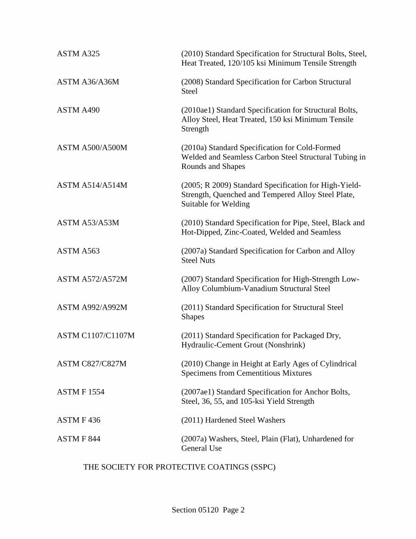
Section 05120 Page 2
ASTM A325 (2010) Standard Specification for Structural Bolts, Steel, Heat Treated, 120/105 ksi Minimum Tensile Strength
ASTM A36/A36M (2008) Standard Specification for Carbon Structural
Steel
ASTM A490 (2010ae1) Standard Specification for Structural Bolts, Alloy Steel, Heat Treated, 150 ksi Minimum Tensile Strength
ASTM A500/A500M (2010a) Standard Specification for Cold-Formed
Welded and Seamless Carbon Steel Structural Tubing in Rounds and Shapes
ASTM A514/A514M (2005; R 2009) Standard Specification for High-Yield-
Strength, Quenched and Tempered Alloy Steel Plate, Suitable for Welding
ASTM A53/A53M (2010) Standard Specification for Pipe, Steel, Black and
Hot-Dipped, Zinc-Coated, Welded and Seamless
ASTM A563 (2007a) Standard Specification for Carbon and Alloy Steel Nuts
ASTM A572/A572M (2007) Standard Specification for High-Strength Low-
Alloy Columbium-Vanadium Structural Steel
ASTM A992/A992M (2011) Standard Specification for Structural Steel Shapes
ASTM C1107/C1107M (2011) Standard Specification for Packaged Dry,
Hydraulic-Cement Grout (Nonshrink)
ASTM C827/C827M (2010) Change in Height at Early Ages of Cylindrical Specimens from Cementitious Mixtures
ASTM F 1554 (2007ae1) Standard Specification for Anchor Bolts,
Steel, 36, 55, and 105-ksi Yield Strength
ASTM F 436 (2011) Hardened Steel Washers
ASTM F 844 (2007a) Washers, Steel, Plain (Flat), Unhardened for General Use
THE SOCIETY FOR PROTECTIVE COATINGS (SSPC)
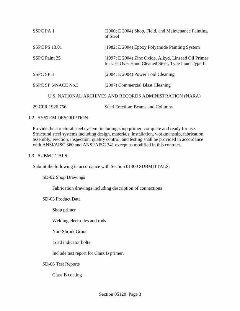
Section 05120 Page 3
SSPC PA 1 (2000; E 2004) Shop, Field, and Maintenance Painting of Steel
SSPC PS 13.01 (1982; E 2004) Epoxy Polyamide Painting System
SSPC Paint 25 (1997; E 2004) Zinc Oxide, Alkyd, Linseed Oil Primer
for Use Over Hand Cleaned Steel, Type I and Type II
SSPC SP 3 (2004; E 2004) Power Tool Cleaning
SSPC SP 6/NACE No.3 (2007) Commercial Blast Cleaning
U.S. NATIONAL ARCHIVES AND RECORDS ADMINISTRATION (NARA)
29 CFR 1926.756 Steel Erection; Beams and Columns 1.2 SYSTEM DESCRIPTION
Provide the structural steel system, including shop primer, complete and ready for use. Structural steel systems including design, materials, installation, workmanship, fabrication, assembly, erection, inspection, quality control, and testing shall be provided in accordance with ANSI/AISC 360 and ANSI/AISC 341 except as modified in this contract.
1.3 SUBMITTALS
Submit the following in accordance with Section 01300 SUBMITTALS:
SD-02 Shop Drawings
Fabrication drawings including description of connections
SD-03 Product Data
Shop primer
Welding electrodes and rods
Non-Shrink Grout
Load indicator bolts
Include test report for Class B primer.
SD-06 Test Reports
Class B coating
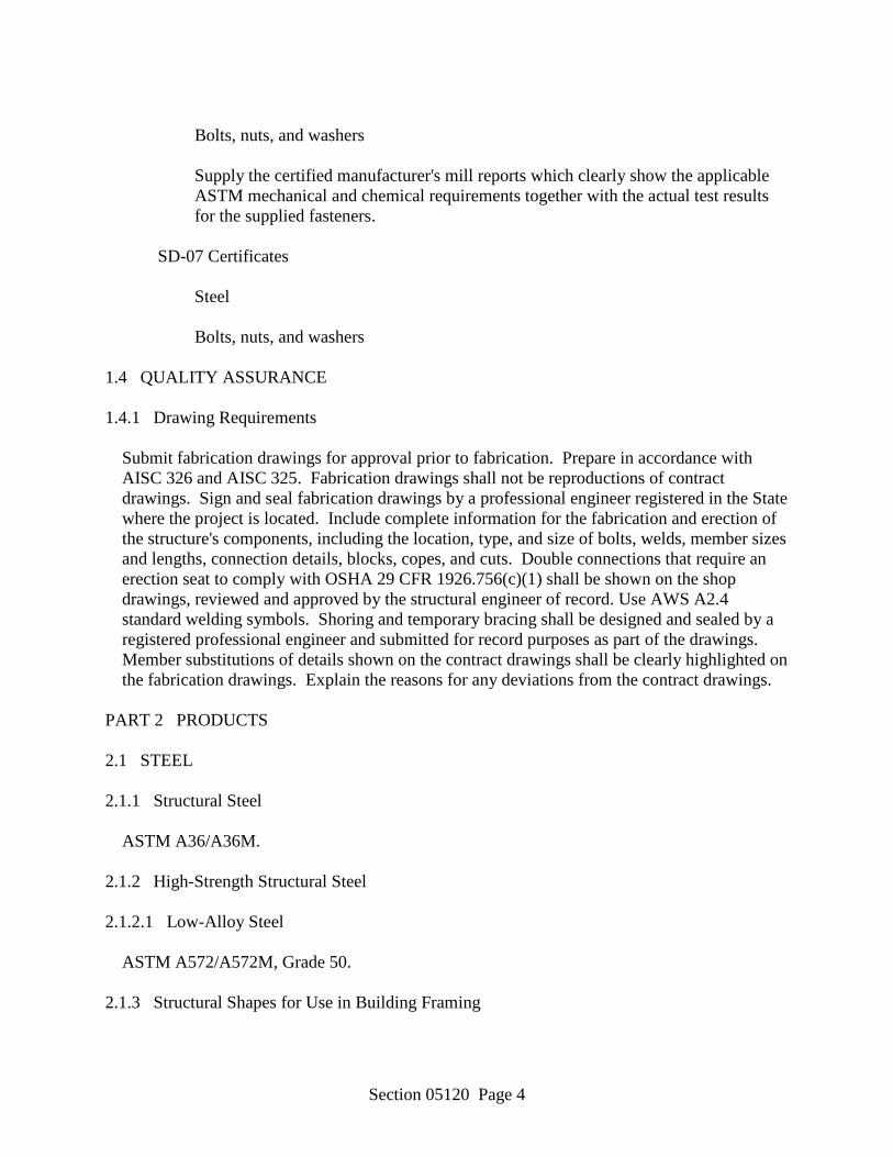
Section 05120 Page 4
Bolts, nuts, and washers
Supply the certified manufacturer's mill reports which clearly show the applicable ASTM mechanical and chemical requirements together with the actual test results for the supplied fasteners.
SD-07 Certificates
Steel
Bolts, nuts, and washers
1.4 QUALITY ASSURANCE 1.4.1 Drawing Requirements
Submit fabrication drawings for approval prior to fabrication. Prepare in accordance with AISC 326 and AISC 325. Fabrication drawings shall not be reproductions of contract drawings. Sign and seal fabrication drawings by a professional engineer registered in the State where the project is located. Include complete information for the fabrication and erection of the structure's components, including the location, type, and size of bolts, welds, member sizes and lengths, connection details, blocks, copes, and cuts. Double connections that require an erection seat to comply with OSHA 29 CFR 1926.756(c)(1) shall be shown on the shop drawings, reviewed and approved by the structural engineer of record. Use AWS A2.4 standard welding symbols. Shoring and temporary bracing shall be designed and sealed by a registered professional engineer and submitted for record purposes as part of the drawings. Member substitutions of details shown on the contract drawings shall be clearly highlighted on the fabrication drawings. Explain the reasons for any deviations from the contract drawings.
PART 2 PRODUCTS 2.1 STEEL 2.1.1 Structural Steel
ASTM A36/A36M. 2.1.2 High-Strength Structural Steel 2.1.2.1 Low-Alloy Steel
ASTM A572/A572M, Grade 50. 2.1.3 Structural Shapes for Use in Building Framing
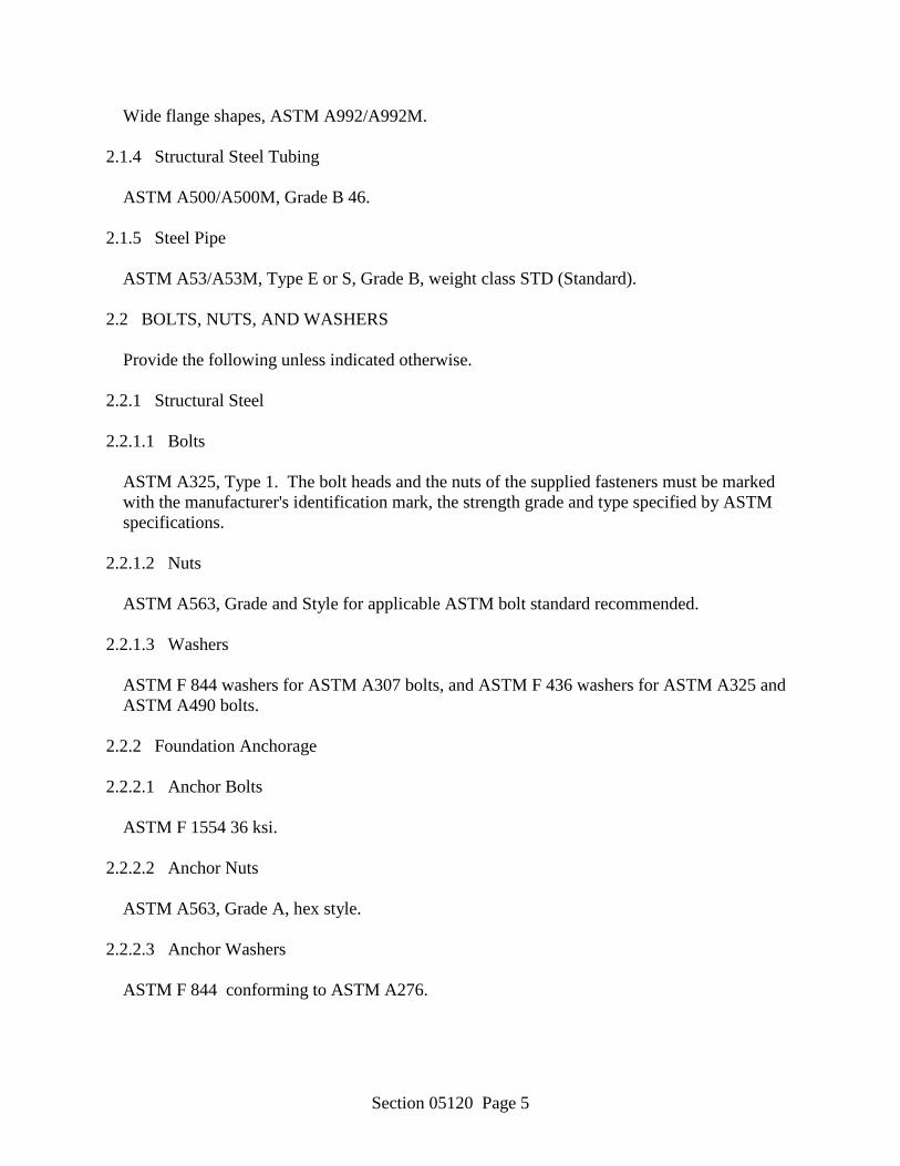
Section 05120 Page 5
Wide flange shapes, ASTM A992/A992M. 2.1.4 Structural Steel Tubing
ASTM A500/A500M, Grade B 46. 2.1.5 Steel Pipe
ASTM A53/A53M, Type E or S, Grade B, weight class STD (Standard). 2.2 BOLTS, NUTS, AND WASHERS
Provide the following unless indicated otherwise. 2.2.1 Structural Steel 2.2.1.1 Bolts
ASTM A325, Type 1. The bolt heads and the nuts of the supplied fasteners must be marked with the manufacturer's identification mark, the strength grade and type specified by ASTM specifications.
2.2.1.2 Nuts
ASTM A563, Grade and Style for applicable ASTM bolt standard recommended. 2.2.1.3 Washers
ASTM F 844 washers for ASTM A307 bolts, and ASTM F 436 washers for ASTM A325 and ASTM A490 bolts.
2.2.2 Foundation Anchorage 2.2.2.1 Anchor Bolts
ASTM F 1554 36 ksi. 2.2.2.2 Anchor Nuts
ASTM A563, Grade A, hex style. 2.2.2.3 Anchor Washers
ASTM F 844 conforming to ASTM A276.
Section 05120 Page 6
2.2.2.4 Anchor Plate Washers
ASTM A36/A36M conforming to ASTM A276. 2.2.3 Load Indicator Bolts
ASTM A325, Type 1; ASTM A490, Type 1, with a manufactured notch between the bolt tip and threads. The bolt shall be designed to react to the opposing rotational torques applied by the installation wrench, with the bolt tip automatically shearing off when the proper tension is obtained.
2.3 STRUCTURAL STEEL ACCESSORIES 2.3.1 Welding Electrodes and Rods
AWS D1.1/D1.1M. 2.3.2 Non-Shrink Grout
ASTM C1107/C1107M, with no ASTM C827/C827M shrinkage. 2.3.3 Welded Shear Stud Connectors
AWS D1.1/D1.1M. 2.4 SHOP PRIMER
SSPC Paint 25, (alkyd primer) or SSPC PS 13.01 epoxy-polyamide, green primer (Form 150) type 1, except provide a Class B coating in accordance with AISC 325 for slip critical joints. Primer shall conform to Federal, State, and local VOC regulations. If flash rusting occurs, re-clean the surface prior to application of primer.
2.5 FABRICATION 2.5.1 Markings
Prior to erection, members shall be identified by a painted erection mark. Connecting parts assembled in the shop for reaming holes in field connections shall be match marked with scratch and notch marks. Do not locate erection markings on areas to be welded. Do not locate match markings in areas that will decrease member strength or cause stress concentrations.
2.5.2 Shop Primer
Shop prime structural steel, except as modified herein, in accordance with SSPC PA 1. Do not prime steel surfaces embedded in concrete, galvanized surfaces, or surfaces within 0.5 inch of
Section 05120 Page 7
the toe of the welds prior to welding (except surfaces on which metal decking is to be welded). Slip critical surfaces shall be primed with a Class B coating. Prior to assembly, prime surfaces which will be concealed or inaccessible after assembly. Do not apply primer in foggy or rainy weather; when the ambient temperature is below 45 degrees F or over 95 degrees F; or when the primer may be exposed to temperatures below 40 degrees F within 48 hours after application, unless approved otherwise by the Contracting Officer.
2.5.2.1 Cleaning
SSPC SP 6/NACE No.3, except steel exposed in spaces above ceilings, attic spaces, furred spaces, and chases that will be hidden to view in finished construction may be cleaned to SSPC SP 3 when recommended by the shop primer manufacturer. Maintain steel surfaces free from rust, dirt, oil, grease, and other contaminants through final assembly.
2.5.2.2 Primer
Apply primer to a minimum dry film thickness of 2.0 mil except provide the Class B coating for slip critical joints in accordance with the coating manufacturer's recommendations. Repair damaged primed surfaces with an additional coat of primer.
2.6 DRAINAGE HOLES
Adequate drainage holes shall be drilled to eliminate water traps. Hole diameter shall be 1/2 inch and location shall be indicated on the detail drawings. Hole size and location shall not affect the structural integrity.
PART 3 EXECUTION 3.1 FABRICATION
Fabrication shall be in accordance with the applicable provisions of AISC 325. Fabrication and assembly shall be done in the shop to the greatest extent possible. The fabricating plant shall be certified under the AISC 201 for Category CSTD structural steelwork.
3.2 ERECTION
a. Erection of structural steel, except as indicated in item b. below, shall be in accordance with the applicable provisions of AISC 325. Erection plan shall be reviewed, stamped and sealed by a licensed structural engineer.
b. For low-rise structural steel buildings (60 feet tall or less and a maximum of 2 stories), the
erection plan shall conform to AISC 303 and the structure shall be erected in accordance with AISC 810.
Section 05120 Page 8
Provide for drainage in structural steel. After final positioning of steel members, provide full bearing under base plates and bearing plates using nonshrink grout. Place nonshrink grout in accordance with the manufacturer's instructions.
3.2.1 STORAGE
Material shall be stored out of contact with the ground in such manner and location as will minimize deterioration.
3.3 CONNECTIONS
Except as modified in this section, connections not detailed shall be designed in accordance with ANSI/AISC 360. Build connections into existing work. Do not tighten anchor bolts set in concrete with impact torque wrenches. Punch, subpunch and ream, or drill bolt holes perpendicular to the surface of the member. Holes shall not be cut or enlarged by burning. Bolts, nuts, and washers shall be clean of dirt and rust, and lubricated immediately prior to installation.
3.3.1 Common Grade Bolts
ASTM A307 bolts shall be tightened to a "snug tight" fit. "Snug tight" is the tightness that exists when plies in a joint are in firm contact. If firm contact of joint plies cannot be obtained with a few impacts of an impact wrench, or the full effort of a man using a spud wrench, contact the Contracting Officer for further instructions.
3.3.2 High-Strength Bolts
ASTM A325 and ASTM A490 bolts shall be fully tensioned to 70 percent of their minimum tensile strength. Provide load indicator bolts, bolted connections. Direct tension indicator tightening, or installation of alternate design fasteners, shall be the only acceptable tightening methods. Bolts shall be installed in connection holes and initially brought to a snug tight fit. After the initial tightening procedure, bolts shall then be fully tensioned, progressing from the most rigid part of a connection to the free edges.
3.4 GAS CUTTING
Use of gas-cutting torch in the field for correcting fabrication errors will not be permitted on any major member in the structural framing. Use of a gas cutting torch will be permitted on minor members not under stress only after approval has been obtained from the Contracting Officer.
3.5 WELDING
AWS D1.1/D1.1M, except use only shielded metal arc welding and low hydrogen electrodes for ASTM A514/A514M steel. Do not stress relieve ASTM A514/A514M steel by heat treatment. Provide AWS D1.1/D1.1M qualified welders, welding operators, and tackers.
Section 05120 Page 9
The Contractor shall develop and submit the Welding Procedure Specifications (WPS) for all welding, including welding done using prequalified procedures. Prequalified procedures may be submitted for information only; however, procedures that are not prequalified shall be submitted for approval.
3.5.1 Removal of Temporary Welds, Run-Off Plates, and Backing Strips
Remove only from finished areas. 3.6 SHOP PRIMER REPAIR
Repair shop primer in accordance with the paint manufacturer's recommendation for surfaces damaged by handling, transporting, cutting, welding, or bolting.
3.6.1 Field Priming
Field priming of steel exposed to the weather, or located in building areas without HVAC for control of relative humidity. After erection, the field bolt heads and nuts, field welds, and any abrasions in the shop coat shall be cleaned and primed with paint of the same quality as that used for the shop coat.
3.7 FIELD QUALITY CONTROL
Perform field tests, and provide labor, equipment, and incidentals required for testing. The Contracting Officer shall be notified in writing of defective welds, bolts, nuts, and washers within 7 working days of the date of weld inspection.
3.7.1 Welds 3.7.1.1 Visual Inspection
AWS D1.1/D1.1M. Furnish the services of AWS-certified welding inspectors for fabrication and erection inspection and testing and verification inspections. Welding inspectors shall visually inspect and mark welds, including fillet weld end returns.
3.7.2 High-Strength Bolts 3.7.2.1 Testing Bolt, Nut, and Washer Assemblies
Test a minimum of 3 bolt, nut, and washer assemblies from each mill certificate batch in a tension measuring device at the job site prior to the beginning of bolting start-up. Demonstrate that the bolts and nuts, when used together, can develop tension not less than the provisions specified in ANSI/AISC 360, depending on bolt size and grade. The bolt tension shall be developed by tightening the nut. A representative of the manufacturer or supplier
Section 05120 Page 10
shall be present to ensure that the fasteners are properly used, and to demonstrate that the fastener assemblies supplied satisfy the specified requirements.
3.7.2.2 Inspection
Inspection procedures shall be in accordance with ANSI/AISC 360. Confirm and report to the Contracting Officer that the materials meet the project specification and that they are properly stored. Confirm that the faying surfaces have been properly prepared before the connections are assembled. Observe the specified job site testing and calibration, and confirm that the procedure to be used provides the required tension. Monitor the work to ensure the testing procedures are routinely followed on joints that are specified to be fully tensioned.
-- End of Section --
Section 06410 Page 1
SECTION 06410 LAMINATE CLAD ARCHITECTURAL CASEWORK
PART 1 GENERAL 1.1 REFERENCES
The publications listed below form a part of this specification to the extent referenced. The publications are referred to within the text by the basic designation only.
AMERICAN NATIONAL STANDARDS INSTITUTE (ANSI)
ANSI A161.2 (1998) Decorative Laminate Countertops, Performance
Standards for Fabricated High Pressure
ANSI A208.2 (2002) Medium Density Fiberboard (MDF) For Interior Applications
ARCHITECTURAL WOODWORK INSTITUTE (AWI)
AWI Qual Stds (2003) AWI Quality Standards
ASTM INTERNATIONAL (ASTM)
ASTM E 84 (2004) Surface Burning Characteristics of Building
Materials
ASTM F 547 (2001) Nails for Use with Wood and Wood-Base Materials
BUILDERS HARDWARE MANUFACTURERS ASSOCIATION (BHMA)
BHMA A156.9 (2003) Cabinet Hardware
NATIONAL ELECTRICAL MANUFACTURERS ASSOCIATION (NEMA)
NEMA LD 3 (2000) High-Pressure Decorative Laminates
WINDOW AND DOOR MANUFACTURERS ASSOCIATION (WDMA)
WDMA I.S. 1-A (1997) Architectural Wood Flush Doors
1.2 GENERAL DESCRIPTION
Work in this section includes laminate clad custom casework cabinets as shown on the drawings and as described in this specification. This Section includes high-pressure laminate
Section 06410 Page 2
surfacing and cabinet hardware. All exposed and semi-exposed surfaces, whose finish is not otherwise noted on the drawings or finish schedule, shall be sanded smooth and shall receive a clear finish of polyurethane.
1.3 SUBMITTALS
The following shall be submitted in accordance with Section 01300 SUBMITTALS:
Shop Drawings
Shop Drawings Installation
Shop drawings showing all fabricated casework items in plan view, elevations and cross-sections to accurately indicate materials used, details of construction, dimensions, methods of fastening and erection, and installation methods proposed. Shop drawing casework items shall be clearly cross-referenced to casework items located on the project drawings. Shop drawings shall include a color schedule of all casework items to include all countertop, exposed, and semi-exposed cabinet finishes to include finish material manufacturer, pattern, and color.
Product Data
Wood Materials Wood Finishes Finish Schedule
Descriptive data which provides narrative written verification of all types of construction materials and finishes, methods of construction, etc. not clearly illustrated on the submitted shop drawings. Data shall provide written verification of conformance with AWI Qual Stds for the quality indicated to include materials, tolerances, and types of construction. Both the manufacturer of materials and the fabricator shall submit available literature which describes re-cycled product content, operations and processes in place that support efficient use of natural resources, energy efficiency, emissions of ozone depleting chemicals, management of water and operational waste, indoor environmental quality, and other production techniques supporting sustainable design and products.
Samples
Plastic Laminates
Two samples of each plastic laminate pattern and color. Samples shall be a minimum of 5 by 7 inches in size.
Certificates
Section 06410 Page 3
Quality Assurance Laminate Clad Casework
A quality control statement which illustrates compliance with and understanding of AWI Qual Stds requirements, in general, and the specific AWI Qual Stds requirements provided in this specification. The quality control statement shall also certify a minimum of ten years contractor's experience in laminate clad casework fabrication and construction. The quality control statement shall provide a list of a minimum of five successfully completed projects of a similar scope, size, and complexity.
1.4 QUALITY ASSURANCE
Unless otherwise noted on the drawings, all materials, construction methods, and fabrication shall conform to and comply with the premium grade quality standards as outlined in AWI Qual Stds, Section 400G and Section 400B for laminate clad cabinets. These standards shall apply in lieu of omissions or specific requirements in this specification. Contractors and their personnel engaged in the work shall be able to demonstrate successful experience with work of comparable extent, complexity and quality to that shown and specified. Contractor must demonstrate knowledge and understanding of AWI Qual Stds requirements for the quality grade indicated.
1.5 DELIVERY AND STORAGE
Casework may be delivered knockdown or fully assembled. All units shall be delivered to the site in undamaged condition, stored off the ground in fully enclosed areas, and protected from damage. The storage area shall be well ventilated and not subject to extreme changes in temperature or humidity.
1.6 SEQUENCING AND SCHEDULING
Work shall be coordinated with other trades. Units shall not be installed in any room or space until painting and ceiling installation are complete within the room where the units are located. Floor cabinets shall be installed before finished flooring materials are installed.
1.7 PROJECT/SITE CONDITIONS
Field measurements shall be verified as indicated in the shop drawings before fabrication. PART 2 PRODUCTS 2.1 WOOD MATERIALS 2.1.1 Lumber
Section 06410 Page 4
a. All framing lumber shall be kiln-dried Grade III to dimensions as shown on the drawings. Frame front, where indicated on the drawings, shall be nominal 3/4 inch hardwood.
b. Standing or running trim casework components which are specified to receive a transparent finish shall be birch hardwood species, plain sawn. AWI grade shall be premium. Location, shape, and dimensions shall be as indicated on the drawings.
2.1.2 Panel Products 2.1.2.1 Plywood
All plywood panels used for framing purposes shall be veneer core hardwood plywood, AWI Qual Stds Grade AA. Nominal thickness of plywood panels shall be as indicated in this specification and on the drawings.
2.1.2.2 Medium Density Fiberboard
Medium density fiberboard (MDF) shall be an acceptable panel substrate where noted on the drawings. Medium density fiberboard shall meet the minimum standards listed in ANSI A208.2.
2.2 SOLID POLYMER MATERIAL
Solid surfacing casework components shall conform to the requirements of Section 06611 SOLID POLYMER (SOLID SURFACING) FABRICATIONS.
2.3 HIGH PRESSURE DECORATIVE LAMINATE (HPDL)
All plastic laminates shall meet the requirements of NEMA LD 3 and ANSI A161.2 for high-pressure decorative laminates. Design, colors, surface finish and texture, and locations shall be as selected by Architect from manufacturers' standard color chart. Plastic laminate types and nominal minimum thicknesses for casework components shall be as indicated in the following paragraphs.
2.3.1 Horizontal General Purpose Standard (HGS) Grade
Horizontal general purpose standard grade plastic laminate shall be 0.048 inches (plus or minus 0.005 inches) in thickness. This laminate grade is intended for horizontal surfaces where postforming is not required.
2.3.2 Vertical General Purpose Standard (VGS) Grade
Vertical general purpose standard grade plastic laminate shall be 0.028 inches (plus or minus 0.004 inches) in thickness. This laminate grade is intended for exposed exterior vertical surfaces of casework components where postforming is not required.
Section 06410 Page 5
2.3.3 Horizontal General Purpose Postformable (HGP) Grade
Horizontal general purpose postformable grade plastic laminate shall be 0.042 inches (plus or minus 0.005 inches) in thickness. This laminate grade is intended for horizontal surfaces where post forming is required.
2.3.4 Vertical General Purpose Postformable (VGP) Grade
Vertical general purpose postformable grade plastic laminate shall be 0.028 inches (plus or minus 0.004 inches) in thickness. This laminate grade is intended for exposed exterior vertical surfaces of components where postforming is required for curved surfaces.
2.3.5 Horizontal General Purpose Fire Rated (HGF) Grade
Horizontal general purpose fire rated grade plastic laminate shall be 0.048 inches (plus or minus 0.005 inches) in thickness. Laminate grade shall have a class 1, class A fire rating in accordance with ASTM E 84.
2.3.6 Cabinet Liner Standard (CLS) Grade
Cabinet liner standard grade plastic laminate shall be 0.020 inches in thickness. This laminate grade is intended for light duty semi-exposed interior surfaces of casework components.
2.3.7 Backing Sheet (BK) Grade
Undecorated backing sheet grade laminate is formulated specifically to be used on the backside of plastic laminated panel substrates to enhance dimensional stability of the substrate. Backing sheet thickness shall be 0.020 inches. Backing sheets shall be provided for all laminated casework components where plastic laminate finish is applied to only one surface of the component substrate.
2.4 THERMOSET DECORATIVE OVERLAYS (MELAMINE)
Thermoset decorative overlays (melamine panels) shall be used for casework cabinet interior, drawer interior surfaces.
2.5 EDGE BANDING
Edge banding for casework doors and drawer fronts shall be PVC vinyl and shall be 0.020 inch thick. Material width shall be 15/16 inches. Color and pattern shall match exposed door and drawer front laminate pattern and color.
2.6 CABINET HARDWARE
All hardware shall conform to BHMA A156.9, unless otherwise noted, and shall consist of the following components:
Section 06410 Page 6
a. Door Hinges: Frameless concealed hinge type, BHMA No. B51602.
b. Cabinet Pulls: Wire, back mounted type, BHMA No. B52011.
c. Drawer Slide: Side mounted type, BHMA No. B55051 with full extension and a minimum 75 pound load capacity. Slides shall include an integral stop to avoid accidental drawer removal.
d. Adjustable Shelf Support System: 1) Recessed (mortised) metal standards, BHMA No. B54071, finish: Stainless steel. Support clips for the standards shall be [open type, BHMA No. B04091, finish: Stainless steel.
2.7 FASTENERS
Nails, screws, and other suitable fasteners shall be the size and type best suited for the purpose and shall conform to ASTM F 547 where applicable.
2.8 ADHESIVES, CAULKS, AND SEALANTS 2.8.1 Adhesives
Adhesives shall be of a formula and type recommended by AWI. Adhesives shall be selected for their ability to provide a durable, permanent bond and shall take into consideration such factors as materials to be bonded, expansion and contraction, bond strength, fire rating, and moisture resistance. Adhesives shall meet local regulations regarding VOC emissions and off-gassing.
2.8.1.1 Wood Joinery
Adhesives used to bond wood members shall be a Type II for interior use polyvinyl acetate resin emulsion. Adhesives shall withstand a bond test as described in WDMA I.S. 1-A.
2.8.1.2 Laminate Adhesive
Adhesive used to join high-pressure decorative laminate to wood shall be adhesive consistent with AWI and laminate manufacturer's recommendations. PVC edgebanding shall be adhered using a polymer-based hot melt glue.
2.8.2 Caulk
Caulk used to fill voids and joints between laminated components and between laminated components and adjacent surfaces shall be clear, 100 percent silicone.
Section 06410 Page 7
2.8.3 Sealant
Sealant shall be of a type and composition recommended by the substrate manufacturer to provide a moisture barrier at sink cutouts and all other locations where unfinished substrate edges may be subjected to moisture.
2.9 ACCCESSORIES 2.9.1 Grommets
Grommets shall be plastic material for cutouts with a diameter of 2 inches. Locations shall be as indicated on the drawings.
2.10 FABRICATION
Fabrication and assembly of components shall be accomplished at the shop site to the maximum extent possible. Construction and fabrication of cabinets and their components shall meet or exceed the requirements for AWI premium grade unless otherwise indicated in this specification. Cabinet style, in accordance with AWI Qual Stds, Section 400-G descriptions, shall be flush overlay.
2.10.1 Base and Wall Cabinet Case Body 2.10.1.1 Cabinet Components
Frame members shall be glued-together, kiln-dried hardwood lumber. Top corners, bottom corners, and cabinet bottoms shall be braced with either hardwood blocks or water-resistant glue and nailed in place metal or plastic corner braces. Cabinet components shall be constructed from the following materials and thicknesses:
a. Body Members (Ends, Divisions, Bottoms, and Tops): 3/4 inch veneer core plywood panel product.
b. Face Frames and Rails: 3/4 inch panel product.
c. Shelving: 3/4 inch veneer core plywood panel product.
d. Cabinet Backs: 1/4 inch veneer core plywood panel product.
e. Drawer Sides, Backs, and Subfronts: 1/2 inch panel product.
f. Drawer Bottoms: 1/4 inch veneer core plywood panel product.
g. Door and Drawer Fronts: 3/4-inch medium density fiberboard 9MDF panel product.

Section 06410 Page 8
2.10.1.2 Joinery Method for Case Body Members
a. Tops, Exposed Ends, and Bottoms.
1) Steel "European" assembly screws (1-1/2 inch from end, 5 inch on center, fasteners will not be visible on exposed parts).
2) Doweled, glued under pressure (approx. 4 dowels per 12 inches of joint).
3) Stop dado, glued under pressure, and either nailed, stapled or screwed (fasteners will not be visible on exposed parts).
b. Exposed End Corner and Face Frame Attachment.
1) For mitered joint: lock miter or spline or biscuit, glued under pressure (no visible fasteners).
2) For non-mitered joint (90 degree): butt joint glued under pressure (no visible fasteners). 3) Butt joint, glued and nailed.
c. Cabinet Backs (Wall Hung Cabinets): Wall hung cabinet backs must not be relied upon to support the full weight of the cabinet and its anticipated load for hanging/mounting purposes. Method of back joinery and hanging/mounting mechanisms should transfer the load to case body members. Fabrication method shall be:
1) Full bound, captured in grooves on cabinet sides, top, and bottom. Cabinet backs for floor standing cabinets shall be side bound, captured in grooves; glued and fastened to top and bottom.
2) Full overlay, plant-on backs with minimum back thickness of 1/2 inch and minimum No. 12 plated (no case hardened) screws spaced a minimum 3 inches on center. Edge of back shall not be exposed on finished sides. Anchor strips are not required when so attached.
d. Cabinet Backs (Floor Standing Cabinets).
1) Side bound, captured in grooves; glued and fastened to top and bottom.
2) Full overlay, plant-on backs with minimum back thickness of 1/2 inch and minimum No. 12 plated (no case hardened) screws spaced a minimum 3 inches on center. Edge of back shall not be exposed on finished sides. Anchor strips are not required when so attached.
e. Wall Anchor Strips shall be required for all cabinets with backs less than 1/2 inch thick. Strips shall consist of minimum 1/2 inch thick lumber, minimum 2-1/2 inches
Section 06410 Page 9
width; securely attached to wall side of cabinet back - top and bottom for wall hung cabinets, top only for floor standing cabinets.
2.10.2 Cabinet Floor Base
Floor cabinets shall be mounted on a base constructed of <MET>19 mm </MET>3/4 inch veneer core exterior plywood. Base assembly components shall be a moisture-resistant panel product. Finished height for each cabinet base shall be as indicated on the drawings. Bottom edge of the cabinet door or drawer face shall be flush with top of base.
2.10.3 Cabinet Door and Drawer Fronts
Door and drawer fronts shall be fabricated from 3/4 inch medium density fiberboard (MDF). All door and drawer front edges shall be surfaced with high pressure plastic laminate, color and pattern to match exterior face laminate.
2.10.4 Drawer Assembly 2.10.4.1 Drawer Components
Drawer components shall consist of a removable drawer front, sides, backs, and bottom. Drawer components shall be constructed of the following materials and thicknesses:
a. Drawer Sides and Back For Thermoset Decorative Overlay (melamine) Finish: 1/2 inch thick medium density particleboard or MDF fiberboard substrate.
b. Drawer Bottom: 1/4 inch thick thermoset decorative overlay melamine panel product.
2.10.4.2 Drawer Assembly Joinery Method
a. Multiple dovetail (all corners) or French dovetail front/dadoed back, glued under pressure.
b. Doweled, glued under pressure.
c. Lock shoulder, glued and pin nailed.
d. Bottoms shall be set into sides, front, and back, 1/4 inch deep groove with a minimum 3/8 inch standing shoulder.
2.10.5 Shelving 2.10.5.1 General Requirements
Section 06410 Page 10
Shelving shall be fabricated from 3/4 inch veneer core plywood. All shelving top and bottom surfaces shall be finished with thermoset decorative overlay (melamine). Shelf edges shall be finished in a thermoset decorative overlay (melamine).
2.10.5.2 Shelf Support System
The shelf support system shall be:
a. Recessed (mortised) metal shelf standards. Standards shall be mortised flush with the finishes surface of the cabinet interior side walls, two per side. Standards shall be positioned and spaced on the side walls to provide a stable shelf surface that eliminates tipping when shelf front is weighted. Standards shall be installed and adjusted vertically to provide a level, stable shelf surface when clips are in place.
2.10.6 Laminate Clad Countertops
Laminate countertop substrate shall be constructed of 3/4 inch veneer core plywood. The substrate shall be moisture-resistant where countertops receive sinks, lavatories, or are subjected to liquids. All substrates shall have sink cutout edges sealed with appropriate sealant against moisture. No joints shall occur at any cutouts. A balanced backer sheet is required.
2.10.6.1 Edge Style
Front and exposed side countertop edges shall be in shapes and to dimensions as shown on the drawings. The countertop edge material shall be:
a. Post formed plastic laminate. Laminate edge shall be integral with countertop surface. Shape and profile shall be bullnose and to dimensions as indicated on the drawings.
b. Hardwood. Species, finish, profile, shape, and dimensions shall be as indicated on the drawings. Hardwood edge shall overlap the exposed countertop laminate edge and shall be installed flush with the countertop laminate surface.
c. Vinyl. Vinyl tee-mould edge shall be in shape, thickness, and color as indicated on the drawings. Tee mould edge shall overlap the exposed countertop laminate edge and shall be installed flush with the countertop laminate surface.
d. Plastic laminate Self Edge. Flat, 90 degree "self " edge. Edge must be applied before top. Laminate edge shall overlap countertop laminate and shall be eased to eliminate sharp corners.
2.10.6.2 Laminate Clad Splashes
Countertop splash substrate shall be 3/4 inch veneer core plywood. Laminate clad backsplash shall be integral with countertop, coved to radius and to dimensions as indicated on the

Section 06410 Page 11
drawings. Side splashes shall be straight profile and provided loose, to be installed at the time of countertop installation. Back and side splash laminate pattern and color shall match the adjacent countertop laminate.
2.10.7 Laminate Application
Laminate application to substrates shall follow the recommended procedures and instructions of the laminate manufacturer and NEMA LD 3, using tools and devices specifically designed for laminate fabrication and application. Provide a balanced backer sheet (Grade BK) wherever only one surface of the component substrate requires a plastic laminate finish. Apply required grade of laminate in full uninterrupted sheets consistent with manufactured sizes using one piece for full length only, using adhesives specified herein or as recommended by the manufacturer. Fit corners and joints hairline. All laminate edges shall be machined flush, filed, sanded, or buffed to remove machine marks and eased (sharp corners removed). Clean up at easing shall be such that no overlap of the member eased is visible. Fabrication shall conform to ANSI A161.2. Laminate types and grades for component surfaces shall be as follows unless otherwise indicated on the drawings:
a. Base/Wall Cabinet Case Body.
1) Exterior (exposed) surfaces to include exposed and semi-exposed face frame surfaces: HPDL Grade VGS.
2) Interior (semi-exposed) surfaces to include interior back wall, bottom, and side walls: HPDL Grade CLS.
b. Adjustable Shelving.
1) Top and bottom surfaces: Thermoset Decorative Overlay (melamine).
2) All edges: Thermoset Decorative Overlay (melamine).
c. Fixed Shelving.
1) Top and bottom surfaces: Thermoset Decorative Overlay (melamine).
2) Exposed edges: Thermoset Decorative Overlay (melamine).
d. Door, Drawer Fronts, Access Panels.
1) Exterior (exposed) and interior (semi-exposed) faces: HPDL Grade VGS.
2) Edges: HPDL Grade VGS.
e. Drawer Assembly.
Section 06410 Page 12
All interior and exterior surfaces: Thermoset Decorative Overlay (melamine).
f. Countertops and Splashes.
All exposed and semi-exposed surfaces: HPDL Grade HGS
g. Tolerances
Flushness, flatness, and joint tolerances of laminated surfaces shall meet the AWI Qual Stds premium grade requirements.
2.10.8 Finishing 2.10.8.1 Filling
No fasteners shall be exposed on laminated surfaces. All nails, screws, and other fasteners in non-laminated cabinet components shall be countersunk and the holes filled with wood filler consistent in color with the wood species.
2.10.8.2 Sanding
All surfaces requiring coatings shall be prepared by sanding with a grit and in a manner that scratches will not show in the final system.
PART 3 EXECUTION 3.1 INSTALLATION
Installation shall comply with applicable requirements for AWI Qual Stds premium quality standards. Countertops and fabricated assemblies shall be installed level, plumb, and true to line, in locations shown on the drawings. Cabinets and other laminate clad casework assemblies shall be attached and anchored securely to the floor and walls with mechanical fasteners that are appropriate for the wall and floor construction.
3.1.1 Anchoring Systems 3.1.1.1 Floor
Base cabinets shall utilize a floor anchoring system. Anchoring and mechanical fasteners shall not be visible from the finished side of the casework assembly. Cabinet assemblies shall be attached to anchored bases without visible fasteners. Where assembly abutts a wall surface, anchoring shall include a minimum 1/2 inch thick lumber or panel product hanging strip, minimum 2-1/2 inch width; securely attached to the top of the wall side of the cabinet back.
3.1.1.2 Wall
Section 06410 Page 13
Cabinet to be wall mounted shall utilize minimum 1/2 inch thick lumber or panel product hanging strips, minimum 2-1/2 inch width; securely attached to the wall side of the cabinet back, both top and bottom.
3.1.2 Countertops
Countertops shall be installed in locations as indicated on the drawings. Countertops shall be fastened to supporting casework structure with mechanical fasteners, hidden from view. All joints formed by the countertop or countertop splash and adjacent wall surfaces shall be filled with a clear silicone caulk. Loose side splashes shall be adhered to both the countertop surface perimeter and the adjacent wall surface with adhesives appropriate for the type of materials to be adhered. Joints between the countertop surface and splash shall be filled with clear silicone caulk in a smooth consistent concave bead. Bead size shall be the minimum necessary to fill the joint and any surrounding voids or cracks.
3.1.3 Hardware
Casework hardware shall be installed in types and locations as indicated on the drawings. Where fully concealed European-style hinges are specified to be used with particleboard or fiberboard doors, the use of plastic or synthetic insertion dowels shall be used to receive 3/16 inch "Euroscrews". The use of wood screws without insertion dowels is prohibited.
3.1.4 Doors, Drawers and Removable Panels
The fitting of doors, drawers and removable panels shall be accomplished within target fitting tolerances for gaps and flushness in accordance with AWI Qual Stds premium grade requirements.
3.1.5 Plumbing Fixtures
Sinks, sink hardware, and other plumbing fixtures shall be installed in locations as indicated on the.
-- End of Section --

Section 06611 Page 1
SECTION 06611 SOLID POLYMER (SOLID SURFACING) FABRICATIONS
PART 1 GENERAL 1.1 REFERENCES
The publications listed below form a part of this specification to the extent referenced. The publications are referred to within the text by the basic designation only.
ASTM INTERNATIONAL (ASTM)
ASTM D2583 (2007) Indentation Hardness of Rigid Plastics by Means
of a Barcol Impressor
ASTM D570 (1998; R 2010e1) Standard Test Method for Water Absorption of Plastics
ASTM D638 (2010) Standard Test Method for Tensile Properties of
Plastics
ASTM D696 (2008) Standard Test Method for Coefficient of Linear Thermal Expansion of Plastics Between -30 degrees C and 30 degrees C With a Vitreous Silica Dilatometer
ASTM E84 (2013c) Standard Test Method for Surface Burning
Characteristics of Building Materials
ASTM G 21 (2009) Determining Resistance of Synthetic Polymeric Materials to Fungi
GREENGUARD ENVIRONMENTAL INSTITUTE (GEI)
GEI Greenguard Standards for Low Emitting Products
INTERNATIONAL ASSOCIATION OF PLUMBING AND MECHANICAL OFFICIALS (IAPMO)
IAPMO Z124.3 (2005) Plastic Lavatories
IAPMO Z124.6 (2007) Plastic Sinks
NATIONAL ELECTRICAL MANUFACTURERS ASSOCIATION (NEMA)
ANSI/NEMA LD 3 (2005) Standard for High-Pressure Decorative
Laminates

Section 06611 Page 2
NSF INTERNATIONAL (NSF)
NSF/ANSI 51 (2009e) Food Equipment Materials
SCIENTIFIC CERTIFICATION SYSTEMS (SCS)
SCS Scientific Certification Systems (SCS)Indoor Advantage
TILE COUNCIL OF NORTH AMERICA (TCNA)
TCA Hdbk (2010) Handbook for Ceramic Tile Installation
1.2 SYSTEM DESCRIPTION
a. Work under this section includes vanity tops, window sills, tub/shower wall panel system and other items utilizing solid polymer (solid surfacing) fabrication as shown on the drawings and as described in this specification. Do not change source of supply for materials after work has started, if the appearance of finished work would be affected.
b. In most instances, installation of solid polymer fabricated components and assemblies will
require strong, correctly located structural support provided by other trades. To provide a stable, sound, secure installation, close coordination is required between the solid polymer fabricator/installer and other trades to ensure that necessary structural wall support, cabinet counter top structural support, proper clearances, and other supporting components are provided for the installation of wall panels, countertops, and all other solid polymer fabrications to the degree and extent recommended by the solid polymer manufacturer.
c. Appropriate staging areas for solid polymer fabrications. Allow variation in component
size and location of openings of plus or minus 1/8 inch. 1.3 SUBMITTALS
Submit the following in accordance with Section 01300 SUBMITTALS:
SD-02 Shop Drawings
Shop Drawings
Installation
SD-03 Product Data
Solid polymer material
Section 06611 Page 3
Qualifications
Fabrications
Certification
SD-04 Samples
Material
Counter and Vanity Tops
SD-06 Test Reports
Solid polymer material
SD-07 Certificates
Fabrications
Qualifications
SD-10 Operation and Maintenance Data
Clean-up 1.4 QUALITY ASSURANCE 1.4.1 Qualifications
To ensure warranty coverage, solid polymer fabricators shall be certified to fabricate by the solid polymer material manufacturer being utilized. Mark all fabrications with the fabricator's certification label affixed in an inconspicuous location. Fabricators shall have a minimum of 5 years of experience working with solid polymer materials. Submit solid polymer manufacturer's certification attesting to fabricator qualification approval.
1.4.2 Sustainable Design Certification
Product shall be third party certified by GEI Greenguard Indoor Air Quality Certified, SCS Scientific Certification Systems Indoor Advantage or equal. Certification shall be performed annually and shall be current.
1.5 DELIVERY, STORAGE, AND HANDLING
Do not deliver materials to project site until areas are ready for installation. Deliver components and materials to the site undamaged, in containers clearly marked and labeled
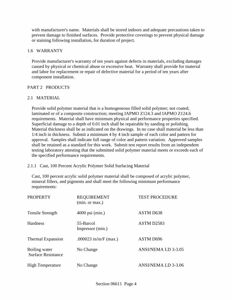
Section 06611 Page 4
with manufacturer's name. Materials shall be stored indoors and adequate precautions taken to prevent damage to finished surfaces. Provide protective coverings to prevent physical damage or staining following installation, for duration of project.
1.6 WARRANTY
Provide manufacturer's warranty of ten years against defects in materials, excluding damages caused by physical or chemical abuse or excessive heat. Warranty shall provide for material and labor for replacement or repair of defective material for a period of ten years after component installation.
PART 2 PRODUCTS 2.1 MATERIAL
Provide solid polymer material that is a homogeneous filled solid polymer; not coated, laminated or of a composite construction; meeting IAPMO Z124.3 and IAPMO Z124.6 requirements. Material shall have minimum physical and performance properties specified. Superficial damage to a depth of 0.01 inch shall be repairable by sanding or polishing. Material thickness shall be as indicated on the drawings. In no case shall material be less than 1/4 inch in thickness. Submit a minimum 4 by 4 inch sample of each color and pattern for approval. Samples shall indicate full range of color and pattern variation. Approved samples shall be retained as a standard for this work. Submit test report results from an independent testing laboratory attesting that the submitted solid polymer material meets or exceeds each of the specified performance requirements.
2.1.1 Cast, 100 Percent Acrylic Polymer Solid Surfacing Material
Cast, 100 percent acrylic solid polymer material shall be composed of acrylic polymer, mineral fillers, and pigments and shall meet the following minimum performance requirements:
PROPERTY REQUIREMENT TEST PROCEDURE (min. or max.) Tensile Strength 4000 psi (min.) ASTM D638 Hardness 55-Barcol ASTM D2583 Impressor (min.) Thermal Expansion .000023 in/in/F (max.) ASTM D696 Boiling water No Change ANSI/NEMA LD 3-3.05 Surface Resistance High Temperature No Change ANSI/NEMA LD 3-3.06
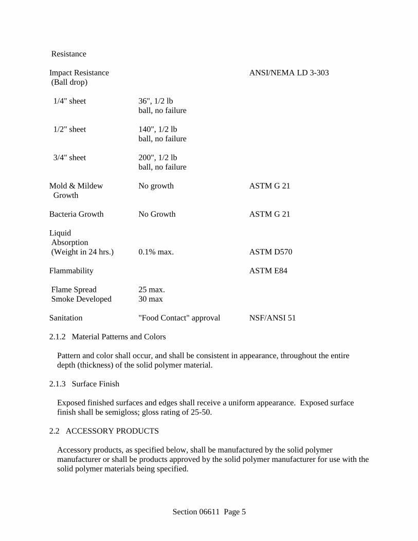
Section 06611 Page 5
Resistance Impact Resistance ANSI/NEMA LD 3-303 (Ball drop) 1/4" sheet 36", 1/2 lb ball, no failure 1/2" sheet 140", 1/2 lb ball, no failure 3/4" sheet 200", 1/2 lb ball, no failure Mold & Mildew No growth ASTM G 21 Growth Bacteria Growth No Growth ASTM G 21 Liquid Absorption (Weight in 24 hrs.) 0.1% max. ASTM D570 Flammability ASTM E84 Flame Spread 25 max. Smoke Developed 30 max Sanitation "Food Contact" approval NSF/ANSI 51 2.1.2 Material Patterns and Colors
Pattern and color shall occur, and shall be consistent in appearance, throughout the entire depth (thickness) of the solid polymer material.
2.1.3 Surface Finish
Exposed finished surfaces and edges shall receive a uniform appearance. Exposed surface finish shall be semigloss; gloss rating of 25-50.
2.2 ACCESSORY PRODUCTS
Accessory products, as specified below, shall be manufactured by the solid polymer manufacturer or shall be products approved by the solid polymer manufacturer for use with the solid polymer materials being specified.
Section 06611 Page 6
2.2.1 Seam Adhesive
Seam adhesive shall be a two-part adhesive kit to create permanent, inconspicuous, non-porous, hard seams and joints by chemical bond between solid polymer materials and components to create a monolithic appearance of the fabrication. Adhesive shall be approved by the solid polymer manufacturer. Adhesive shall be color-matched to the surfaces being bonded where solid-colored, solid polymer materials are being bonded together. The seam adhesive shall be clear or color matched where particulate patterned, solid polymer materials are being bonded together.
2.2.2 Panel Adhesive
Panel adhesive shall be neoprene based panel adhesive meeting TCA Hdbk, Underwriter's Laboratories (UL) listed. Use this adhesive to bond solid polymer components to adjacent and underlying substrates.
2.2.3 Silicone Sealant
Sealant shall be a mildew-resistant, FDA and OSHA Nationally Recognized Testing Laboratory (NRTL) listed silicone sealant or caulk in a clear formulation. The silicone sealant shall be approved for use by the solid polymer manufacturer. Use sealant to seal all expansion joints between solid polymer components and all joints between solid polymer components and other adjacent surfaces such as walls, floors, ceiling, and plumbing fixtures.
2.2.4 Conductive Tape
Conductive tape shall be manufacturer's standard foil tape, 4 mils thick, applied around the edges of cut outs containing hot or cold appliances.
2.2.5 Insulating Felt Tape
Insulating tape shall be manufacturer's standard product for use with drop-in food wells used in commercial food service applications to insulate solid polymer surfaces from hot or cold appliances.
2.2.6 Heat Reflective Tape
Heat reflective tape as recommended by the solid polymer manufacturer for use with cutouts for heat sources.
2.2.7 Mounting Hardware
Provide mounting hardware, including sink/bowl clips, inserts and fasteners for attachment of undermount sinks and lavatories.
Section 06611 Page 7
2.3 FABRICATIONS
Components shall be factory or shop fabricated to sizes and shapes indicated, to the greatest extent practical, in accordance with approved Shop Drawings and manufacturer's requirements. Provide factory cutouts for sinks, lavatories, and plumbing fixtures where indicated on the drawings. Contours and radii shall be routed to template, with edges smooth. Defective and inaccurate work will be rejected. Submit product data indicating product description, fabrication information, and compliance with specified performance requirements for solid polymer, joint adhesive, sealants, and heat reflective tape. Both the manufacturer of materials and the fabricator shall submit a detailed description of operations and processes in place that support efficient use of natural resources, energy efficiency, emissions of ozone depleting chemicals, management of water and operational waste, indoor environmental quality, and other production techniques supporting sustainable design and products.
2.3.1 Joints and Seams
Form joints and seams between solid polymer components using manufacturer's approved seam adhesive. Joints shall be inconspicuous in appearance and without voids to create a monolithic appearance.
2.3.2 Edge Finishing
Rout and finish component edges to a smooth, uniform appearance and finish. Edge shapes and treatments, including any inserts, shall be as detailed on the drawings. Rout all cutouts, then sand all edges smooth. Repair or reject defective or inaccurate work.
2.3.3 Counter and Vanity Top Splashes
Fabricate backsplashes and end splashes from 1/2 inch thick solid surfacing material to be 4 inches high. Backsplashes and end splashes shall be provided at locations indicated on the drawings. Backsplashes shall be shop fabricated and be permanently attached.
2.3.3.1 Permanently Attached Backsplash
Permanently attached backsplashes shall be attached with seam adhesive and to form a radiused coved transition from countertop to backsplash.
2.3.3.2 End Splashes
End splashes shall be provided loose for installation at the jobsite after horizontal surfaces to which they are to be attached have been installed.
2.3.4 Window Stools
Section 06611 Page 8
Fabricate window stools from 3/4 inch thick solid surfacing, solid polymer material. Dimensions, edge shape, and other details shall be selected from manufacturer's available pre-fabricated standards.
2.3.5 Counter and Vanity Tops
Fabricate all solid surfacing, solid polymer counter top and vanity top components from 1/2 inch thick material. Edge details, dimensions, locations, and quantities shall be as indicated on the Drawings. Counter tops shall be complete with 4 inch high permanently attached with coved transition backsplash and loose end splashes at all locations. Attach 2 inch wide reinforcing strip of polymer material under each horizontal counter top seam. Submit a minimum 1 foot wide by 6 inch deep, full size sample for each type of counter top shown on the project drawings. The sample shall include the edge profile and backsplash as detailed on the project drawings. Solid polymer material shall be of a pattern and color as indicated on the drawings. Sample shall include at least one seam. Approved sample shall be retained as standard for this work.
2.3.5.1 Vanity Tops With Bowls
a. One-piece vanity top and bowl fabrications shall be a standard pre-fabricated product provided by the solid polymer manufacturer. Each unit shall include a vanity top with integral backsplash and sink bowl.
PART 3 EXECUTION 3.1 INSTALLATION 3.1.1 Components
Install all components and fabricated units plumb, level, and rigid. Make field joints between solid polymer components using solid polymer manufacturer's approved seam adhesives, to provide a monolithic appearance with joints inconspicuous in the finished work. Attach metal or vitreous china sinks and lavatory bowls to counter tops using solid polymer manufacturer's recommended clear silicone sealant and mounting hardware. Solid polymer sinks and bowls shall be installed using a color-matched seam adhesive.
3.1.2 Silicone Sealant
Use a clear, silicone sealant or caulk to seal all expansion joints between solid polymer components and all joints between solid polymer components and other adjacent surfaces such as walls, floors, ceiling, and plumbing fixtures. Sealant bead shall be smooth and uniform in appearance and shall be the minimum size necessary to bridge any gaps between the solid surfacing material and the adjacent surface. Bead shall be continuous and run the entire length of the joint being sealed.
Section 06611 Page 9
3.1.3 Plumbing
Make plumbing connections to sinks and lavatories. 3.2 CLEAN-UP
Components shall be cleaned after installation and covered to protect against damage during completion of the remaining project items. Components damaged after installation by other trades will be repaired or replaced at the General Contractor's cost. Component supplier will provide a repair/replace cost estimate to the General Contractor who shall approve estimate before repairs are made. Submit a minimum of six copies of maintenance data indicating manufacturer's care, repair and cleaning instructions. Maintenance video shall be provided, if available. Maintenance kit for matte finishes shall be submitted.
-- End of Section --

Section 07600 Page 1
SECTION 07600 FLASHING AND SHEET METAL
PART 1 GENERAL 1.1 REFERENCES
The publications listed below form a part of this specification to the extent referenced. The publications are referred to in the text by the basic designation only.
AMERICAN SOCIETY FOR TESTING AND MATERIALS (ASTM)
ASTM A 653/A 653M (1998) Steel Sheet, Zinc-Coated (Galvanized) or Zinc-
Iron Alloy-Coated (Galvannealed) by the Hot-Dip Process
ASTM B 32 (1996) Solder Metal
ASTM B 69 (1998) Rolled Zinc
ASTM B 209 (1996) Aluminum and Aluminum-Alloy Sheet and Plate
ASTM B 221 (1996) Aluminum and Aluminum-Alloy Extruded Bars,
Rods, Wire, Profiles, and Tubes
ASTM D 4586 (1993) Asphalt Roof Cement, Asbestos-Free
AMERICAN WELDING SOCIETY (AWS)
AWS D1.2 (1997) Structural Welding Code Aluminum
SHEET METAL & AIR CONDITIONING CONTRACTORS' NATIONAL ASSOCIATION (SMACNA)
SMACNA ASMM (1993) Architectural Sheet Metal Manual
1.2 SUBMITTALS
Submit the following in accordance with Section 01300, "Submittals."
Shop Drawings
Covering on flat, sloped, or curved surfaces
Base flashing
Section 07600 Page 2
Counterflashing
Flashing at roof penetrations
Indicate thicknesses, dimensions, fastenings and anchoring methods, expansion joints, and other provisions necessary for thermal expansion and contraction. Scaled manufacturer's catalog data may be submitted for factory fabricated items.
1.3 DELIVERY, HANDLING, AND STORAGE
Package and protect materials during shipment. Uncrate and inspect materials for damage, dampness, and wet-storage stains upon delivery to the job site. Remove from the site and replace damaged materials that cannot be restored to like-new condition. Handle sheet metal items to avoid damage to surfaces, edges, and ends. Store materials in dry, weather-tight, ventilated areas until immediately before installation.
PART 2 PRODUCTS 2.1 MATERIALS
Furnish sheet metal items in 8 to 10 foot lengths. Single pieces less than 8 feet long may be used to connect to factory-fabricated inside and outside corners, and at ends of runs. Factory fabricate corner pieces with minimum 12 inch legs. Provide accessories and other items essential to complete the sheet metal installation. These accessories shall be made of the same materials as the items to which they are applied. Fabricate sheet metal items of the materials specified below and to the gage, thickness, or weight shown in Table I at the end of this section. Sheet metal items shall have mill finish unless specified otherwise. Where more than one material is listed for a particular item in Table I, each is acceptable and may be used except as follows:
2.1.1 Exposed Sheet Metal Items
Shall be of the same material. The following items shall be considered as exposed sheet metal: gutters, including hangers; downspouts; gravel stops and fascias; cap, valley, stepped, base, and eave flashings and related accessories.
2.1.2 Drainage
Do not use copper for an exposed item if drainage from that item will pass over exposed masonry, stonework or other metal surfaces. In addition to the metals listed in Table I, lead-coated copper may be used for such items.
2.1.3 Steel Sheet, Zinc-Coated (Galvanized)
ASTM A 653/A 653M.
Section 07600 Page 3
2.1.3.1 Finish
Exposed exterior items of zinc-coated steel sheet shall have a baked-on, factory-applied color coating of polyvinylidene fluoride or other equivalent fluorocarbon coating applied after metal substrates have been cleaned and pretreated. Finish coating dry-film thickness shall be 0.8 to 1.3 mils and color shall be as selected by the Architect.
2.1.4 Zinc Sheet and Strip
ASTM B 69, Type I, a minimum of 0.024 inch thick. 2.1.5 Aluminum Alloy Sheet and Plate
ASTM B 209, form alloy, and temper appropriate for use. 2.1.5.1 Alclad
When fabricated of aluminum, the following items shall be fabricated of Alclad 3003, Alclad 3004, Alclad 3005, clad on both sides unless otherwise indicated.
a. Hangers
b. Flashing
2.1.5.2 Finish
Exposed exterior sheet metal items of aluminum shall have a baked-on, factory-applied color coating of polyvinylidene fluoride (PVF2) or other equivalent fluorocarbon coating applied after metal substrates have been cleaned and pretreated. Finish coating dry-film thickness shall be 0.8 to 1.3 mils, and color shall be as selected by the Architect.
2.1.6 Aluminum Alloy, Extruded Bars, Rods, Shapes, and Tubes
ASTM B 221. 2.1.7 Solder
ASTM B 32. 2.1.8 Bituminous Plastic Cement
ASTM D 4586, Type I. 2.1.9 Building Paper
Uncreped, reinforced, 20 lb per inch dry tensile strength, 16 hour minimum water resistance.

Section 07600 Page 4
2.1.10 Fasteners
Use the same metal or a metal compatible with the item fastened. Use stainless steel fasteners to fasten dissimilar materials.
PART 3 EXECUTION 3.1 INSTALLATION 3.1.1 Requirements
Make surfaces to receive sheet metal plumb and true, clean, even, smooth, dry, and free of defects and projections which might affect the application. For installation of items not shown in detail or not covered by specifications conform to the applicable requirements of SMACNA ASMM, Architectural Sheet Metal Manual. Provide sheet metal flashing in the angles formed where roof decks abut walls, curbs, ventilators, pipes, or other vertical surfaces and wherever indicated and necessary to make the work watertight. Join sheet metal items together as shown in Table II.
3.1.2 Workmanship
Make lines, arises, and angles sharp and true. Free exposed surfaces from visible wave, warp, and buckle, and tool marks. Fold back exposed edges neatly to form a 1/2 inch hem on the concealed side. Make sheet metal exposed to the weather watertight with provisions for expansion and contraction.
3.1.3 Nailing
Confine nailing of sheet metal generally to sheet metal having a maximum width of 18 inches. Confine nailing of flashing to one edge only. Space nails evenly not over 3 inches on centers and approximately 1/2 inch from edge unless otherwise specified or indicated. Face nailing will not be permitted. Where sheet metal is applied to other than wood surfaces, include in shop drawings, the locations for sleepers and nailing strips required to secure the work. Sleepers and nailing strips are specified in Section 06100, "Rough Carpentry."
3.1.4 Cleats
Provide cleats for sheet metal 18 inches and over in width. Space cleats evenly not over 12 inches on centers unless otherwise specified or indicated. Unless otherwise specified, cleats shall be not less than 2 inches wide by 3 inches long and of the same material and thickness as the sheet metal being installed. Secure one end of the cleat with two nails and the cleat folded back over the nail heads. Lock the other end into the seam. Pretin cleats for soldered seams.
3.1.5 Bolts, Rivets, and Screws
Section 07600 Page 5
Install bolts, rivets, and screws where indicated or required. Provide compatible washers where required to protect surface of sheet metal and to provide a watertight connection.
3.1.6 Seams
Straight and uniform in width and height with no solder showing on the face. 3.1.6.1 Flat-lock Seams
Finish not less than 3/4 inch wide. 3.1.6.2 Lap Seams
Finish soldered seams not less than one inch wide. Overlap seams not soldered, not less than 3 inches.
3.1.6.3 Loose-Lock Expansion Seams
Not less than 3 inches wide; provide minimum one inch movement within the joint. Completely fill the joints with the specified sealant, applied at not less than 1/8 inch thick bed. Sealants are specified in Section 07920, "Joint Sealants."
3.1.6.4 Flat Seams
Make seams in the direction of the flow. 3.1.7 Soldering
Where soldering is specified, it shall apply to copper, terne-coated stainless steel, zinc-coated steel, and stainless steel items.
3.1.7.1 Edges
Pretin edges of sheet metals before soldering. Slowly solder with well heated soldering irons so as to thoroughly heat the seams and completely sweat the solder through the full width of the seam. Scrape or wire-brush the edges of lead-coated material to be soldered to produce a bright surface. Flux brush the seams in before soldering. Treat with soldering acid flux the edges of stainless steel to be pretinned. Solder immediately after application of the flux. Upon completion of soldering, the acid flux residue shall be thoroughly cleaned from the sheet metal with a solution of washing soda in water and rinsed with clean water. Seal the joints in aluminum sheets of 0.040 inch or less in thickness with specified sealants. Do not solder aluminum.
3.1.8 Welding and Mechanical Fastening
Section 07600 Page 6
Use welding for aluminum of thickness greater than 0.040 inch. Aluminum 0.040 inch or less in thickness shall be butted and the space backed with formed flashing plate; or lock joined, mechanically fastened, and filled with sealant as recommended by the aluminum manufacturer.
3.1.8.1 Welding of Aluminum
Use welding of the inert gas, shield-arc type. For procedures, appearance and quality of welds, and the methods used in correcting welding work, conform to AWS D1.2.
3.1.8.2 Mechanical Fastening of Aluminum
Use No. 12, aluminum alloy, sheet metal screws or other suitable aluminum alloy or stainless steel fasteners. Drive fasteners in holes made with a No. 26 drill in securing side laps, end laps, and flashings. Space fasteners 12 inches maximum on centers. Where end lap fasteners are required to improve closure, locate the end lap fasteners not more than 2 inches from the end of the overlapping sheet.
3.1.9 Protection from Contact with Dissimilar Materials 3.1.9.1 Aluminum
Aluminum surfaces shall not directly contact other metals except stainless steel, zinc, or zinc coating. Where aluminum contacts another metal, paint the dissimilar metal with a primer followed by two coats of aluminum paint. Where drainage from a dissimilar metal passes over aluminum, paint the dissimilar metal with a non-lead pigmented paint.
3.1.9.2 Metal Surfaces
Paint surfaces in contact with mortar, concrete, or other masonry materials with alkali-resistant coatings such as heavy-bodied bituminous paint.
3.1.9.3 Wood or Other Absorptive Materials
Paint surfaces that may become repeatedly wet and in contact with metal with two coats of aluminum paint or a coat of heavy-bodied bituminous paint.
3.1.10 Expansion and Contraction
Provide expansion and contraction joints at not more than 32 foot intervals for aluminum and at not more than 40 foot intervals for other metals. Where the distance between the last expansion joint and the end of the continuous run is more than half the required interval, an additional joint shall be provided. Space joints evenly. Join extruded aluminum gravel stops and fascias by expansion and contraction joints spaced not more than 12 feet apart.
Section 07600 Page 7
3.1.11 Base Flashing
Extend up vertical surfaces of the flashing not less than 8 inches and not less than 4 inches under the roof covering. Where finish wall coverings form a counterflashing, extend the vertical leg of the flashing up behind the applied wall covering not less than 6 inches. Overlap the flashing strips with the previously laid flashing not less than 3 inches. Fasten the strips at their upper edge to the deck, with compatible, large-head roofing nails. Solder end laps and provide for expansion and contraction. Extend the metal flashing over crickets at the up-slope side of vertical surfaces extending through sloping roofs, the metal flashings. Extend the metal flashings onto the roof covering not less than 4.5 inches at the lower side of vertical surfaces extending through the roof decks. Install and fit the flashings so as to be completely weathertight. Base flashing for interior and exterior corners shall be factory-fabricated.
3.1.12 Counterflashing
Except where indicated or specified otherwise, insert counterflashing in reglets located from 9 to 10 inches above roof decks, extend down vertical surfaces over upturned vertical leg of base flashings not less than 3 inches. Fold the exposed edges of counterflashings 1/2 inch. Where stepped counterflashings are required, they may be installed in short lengths or may be of the preformed one-piece type. Provide end laps in counterflashings not less than 3 inches and make it weathertight with plastic cement. Do not make lengths of metal counterflashings exceed 10 feet. Form the flashings to the required shapes before installation. Factory-form the corners not less than 12 inches from the angle. Secure the flashings in the reglets with lead wedges and space not more than 18 inches apart; on short runs, place wedges closer together. Fill calked-type reglets or raked joints which receive counterflashing with calking compound. Calking is covered in Section 07920, "Joint Sealants." Turn up the concealed edge of counterflashings built into masonry or concrete walls not less than 1/4 inch and extend not less than 2 inches into the walls. Install counterflashing to provide a spring action against base flashing.
3.1.13 Sheet Metal Covering on Flat, Sloped, or Curved Surfaces
Except as specified or indicated otherwise, cover and flash all minor flat, sloped, or curved surfaces such as crickets, bulkheads, dormers and small decks with metal sheets of the material used for flashing; maximum size of sheets, 16 by 18 inches. Fasten sheets to sheathing with metal cleats. Lock seams and solder. Lock aluminum seams and fill with sealer as recommended by aluminum manufacturer. Provide an underlayment of building paper for all sheet metal covering.
3.1.14 Flashing at Roof Penetrations and Equipment Supports
Provide metal flashing for all pipes, ducts, and conduits projecting through the roof surface and for equipment supports, guy wire anchors, and similar items supported by or attached to the roof deck.
Section 07600 Page 8
3.1.14.1 Single Pipe Vents
See Table I, footnote (a). Set flange of sleeve in bituminous plastic cement and nail 3 inches on centers. Bend the top of sleeve over and extend down into the vent pipe a minimum of 2 inches. For long runs or long rises above the deck, where it is impractical to cover the vent pipe with lead, use a two-piece formed metal housing. Set metal housing with a metal sleeve having a 4 inch roof flange in bituminous plastic cement and nailed 3 inches on centers. Extend sleeve a minimum of 8 inches above the roof deck and lapped a minimum of 3 inches by a metal hood secured to the vent pipe by a draw band. Seal the area of hood in contact with vent pipe with an approved sealant. Sealants are covered under Section 07920, "Joint Sealants."
3.2 PAINTING
Field-paint sheet metal for separation of dissimilar materials. 3.3 CLEANING
Clean exposed sheet metal work at completion of installation. Remove grease and oil films, handling marks, contamination from steel wool, fittings and drilling debris, and scrub-clean. Free the exposed metal surfaces of dents, creases, waves, scratch marks, and solder or weld marks.
3.4 REPAIRS TO FINISH
Scratches, abrasions, and minor surface defects of finish may be repaired in accordance with the manufacturer's printed instructions and as approved. Repair damaged surfaces caused by scratches, blemishes, and variations of color and surface texture. Replace items which cannot be repaired.
Section 07600 Page 9
TABLE I. SHEET METAL WEIGHTS, THICKNESSES, AND GAGES
Zinc- Coated Steel, Sheet Metal Items Aluminum, U.S. Inch Std. Gage ___________________________________________________________________________ Covering on minor flat, pitched or curved surfaces ............ .040 - Flashings: Base ................ .040 24 Cap (Counter-flashing) .032 26 Pipe vent sleeve(a) Extrusions .......... .075 - Sheets, corrugated .......... .032 - Sheets, smooth ...... .050 24 (a) 2.5 pound minimum lead sleeve with 4 inch flange. Where lead sleeve is impractical,
refer to paragraph entitled "Single Pipe Vents" for optional material.
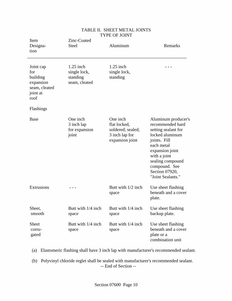
Section 07600 Page 10
TABLE II. SHEET METAL JOINTS TYPE OF JOINT
Item Zinc-Coated Designa- Steel Aluminum Remarks tion ______________________________________________________________________ Joint cap 1.25 inch 1.25 inch - - - for single lock, single lock, building standing standing expansion seam, cleated seam, cleated joint at roof Flashings Base One inch One inch Aluminum producer's 3 inch lap flat locked, recommended hard for expansion soldered; sealed; setting sealant for joint 3 inch lap for locked aluminum expansion joint joints. Fill each metal expansion joint with a joint sealing compound compound. See Section 07920, "Joint Sealants." Extrusions - - - Butt with 1/2 inch Use sheet flashing space beneath and a cover plate. Sheet, Butt with 1/4 inch Butt with 1/4 inch Use sheet flashing smooth space space backup plate. Sheet Butt with 1/4 inch Butt with 1/4 inch Use sheet flashing corru- space space beneath and a cover gated plate or a combination unit (a) Elastomeric flashing shall have 3 inch lap with manufacturer's recommended sealant. (b) Polyvinyl chloride reglet shall be sealed with manufacturer's recommended sealant.
-- End of Section --

Section 07920 Page 1
SECTION 07920 JOINT SEALANTS
PART 1 GENERAL 2.1 REFERENCES
The publications listed below form a part of this specification to the extent referenced. The publications are referred to in the text by the basic designation only.
AMERICAN SOCIETY FOR TESTING AND MATERIALS (ASTM)
ASTM C 834 (1995) Latex Sealants
ASTM C 920 (1995) Elastomeric Joint Sealants
1.1 SUBMITTALS
Submit the following in accordance with Section 01300, "Submittals." 1.1.1 Manufacturer's Catalog Data
a. Sealants
b. Primers
c. Bond breakers
d. Backstops
Data for the sealants shall include shelf life and recommended cleaning solvents. 1.2 ENVIRONMENTAL CONDITIONS
The ambient temperature shall be within the limits of 40 and 100 degrees F when sealant is applied.
1.3 DELIVERY AND STORAGE
Deliver materials to the job site in unopened manufacturers' external shipping containers, with brand names, date of manufacture, color, and material designation clearly marked thereon. Elastomeric sealant containers shall be labeled to identify type, class, grade, and use. Carefully handle and store materials to prevent inclusion of foreign materials or subjection to sustained temperatures exceeding 100 degrees F or less than 40 degrees F.
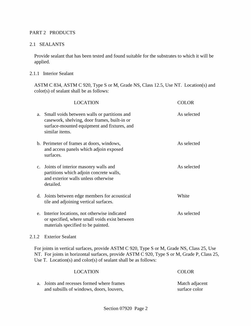
Section 07920 Page 2
PART 2 PRODUCTS 2.1 SEALANTS
Provide sealant that has been tested and found suitable for the substrates to which it will be applied.
2.1.1 Interior Sealant
ASTM C 834, ASTM C 920, Type S or M, Grade NS, Class 12.5, Use NT. Location(s) and color(s) of sealant shall be as follows:
LOCATION COLOR a. Small voids between walls or partitions and As selected casework, shelving, door frames, built-in or
surface-mounted equipment and fixtures, and similar items.
b. Perimeter of frames at doors, windows, As selected and access panels which adjoin exposed surfaces. c. Joints of interior masonry walls and As selected
partitions which adjoin concrete walls, and exterior walls unless otherwise detailed.
d. Joints between edge members for acoustical White
tile and adjoining vertical surfaces. e. Interior locations, not otherwise indicated As selected or specified, where small voids exist between materials specified to be painted. 2.1.2 Exterior Sealant
For joints in vertical surfaces, provide ASTM C 920, Type S or M, Grade NS, Class 25, Use NT. For joints in horizontal surfaces, provide ASTM C 920, Type S or M, Grade P, Class 25, Use T. Location(s) and color(s) of sealant shall be as follows:
LOCATION COLOR a. Joints and recesses formed where frames Match adjacent and subsills of windows, doors, louvers, surface color
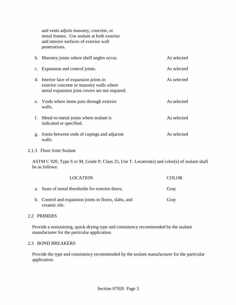
Section 07920 Page 3
and vents adjoin masonry, concrete, or metal frames. Use sealant at both exterior and interior surfaces of exterior wall penetrations. b. Masonry joints where shelf angles occur. As selected c. Expansion and control joints. As selected d. Interior face of expansion joints in As selected exterior concrete or masonry walls where metal expansion joint covers are not required. e. Voids where items pass through exterior As selected walls. f. Metal-to-metal joints where sealant is As selected indicated or specified. g. Joints between ends of copings and adjacent As selected walls. 2.1.3 Floor Joint Sealant
ASTM C 920, Type S or M, Grade P, Class 25, Use T. Location(s) and color(s) of sealant shall be as follows:
LOCATION COLOR a. Seats of metal thresholds for exterior doors. Gray b. Control and expansion joints in floors, slabs, and Gray
ceramic tile. 2.2 PRIMERS
Provide a nonstaining, quick-drying type and consistency recommended by the sealant manufacturer for the particular application.
2.3 BOND BREAKERS
Provide the type and consistency recommended by the sealant manufacturer for the particular application.
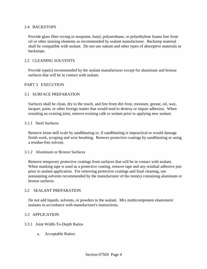
Section 07920 Page 4
2.4 BACKSTOPS
Provide glass fiber roving or neoprene, butyl, polyurethane, or polyethylene foams free from oil or other staining elements as recommended by sealant manufacturer. Backstop material shall be compatible with sealant. Do not use oakum and other types of absorptive materials as backstops.
2.5 CLEANING SOLVENTS
Provide type(s) recommended by the sealant manufacturer except for aluminum and bronze surfaces that will be in contact with sealant.
PART 3 EXECUTION 3.1 SURFACE PREPARATION
Surfaces shall be clean, dry to the touch, and free from dirt frost, moisture, grease, oil, wax, lacquer, paint, or other foreign matter that would tend to destroy or impair adhesion. When resealing an existing joint, remove existing calk or sealant prior to applying new sealant.
3.1.1 Steel Surfaces
Remove loose mill scale by sandblasting or, if sandblasting is impractical or would damage finish work, scraping and wire brushing. Remove protective coatings by sandblasting or using a residue-free solvent.
3.1.2 Aluminum or Bronze Surfaces
Remove temporary protective coatings from surfaces that will be in contact with sealant. When masking tape is used as a protective coating, remove tape and any residual adhesive just prior to sealant application. For removing protective coatings and final cleaning, use nonstaining solvents recommended by the manufacturer of the item(s) containing aluminum or bronze surfaces.
3.2 SEALANT PREPARATION
Do not add liquids, solvents, or powders to the sealant. Mix multicomponent elastomeric sealants in accordance with manufacturer's instructions.
3.3 APPLICATION 3.3.1 Joint Width-To-Depth Ratios
a. Acceptable Ratios:
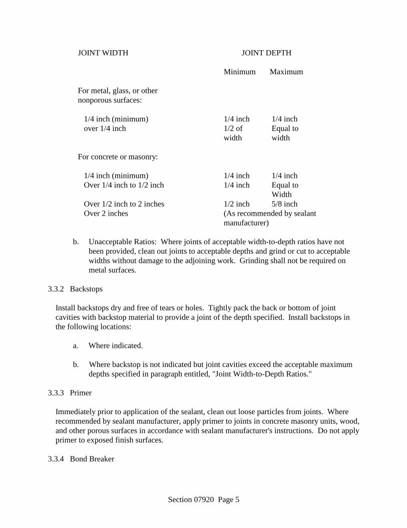
Section 07920 Page 5
JOINT WIDTH JOINT DEPTH Minimum Maximum For metal, glass, or other nonporous surfaces: 1/4 inch (minimum) 1/4 inch 1/4 inch over 1/4 inch 1/2 of Equal to width width For concrete or masonry:
1/4 inch (minimum) 1/4 inch 1/4 inch Over 1/4 inch to 1/2 inch 1/4 inch Equal to
Width Over 1/2 inch to 2 inches 1/2 inch 5/8 inch Over 2 inches (As recommended by sealant manufacturer)
b. Unacceptable Ratios: Where joints of acceptable width-to-depth ratios have not been provided, clean out joints to acceptable depths and grind or cut to acceptable widths without damage to the adjoining work. Grinding shall not be required on metal surfaces.
3.3.2 Backstops
Install backstops dry and free of tears or holes. Tightly pack the back or bottom of joint cavities with backstop material to provide a joint of the depth specified. Install backstops in the following locations:
a. Where indicated.
b. Where backstop is not indicated but joint cavities exceed the acceptable maximum
depths specified in paragraph entitled, "Joint Width-to-Depth Ratios." 3.3.3 Primer
Immediately prior to application of the sealant, clean out loose particles from joints. Where recommended by sealant manufacturer, apply primer to joints in concrete masonry units, wood, and other porous surfaces in accordance with sealant manufacturer's instructions. Do not apply primer to exposed finish surfaces.
3.3.4 Bond Breaker

Section 07920 Page 6
Provide bond breakers to the back or bottom of joint cavities, as recommended by the sealant manufacturer for each type of joint and sealant used, to prevent sealant from adhering to these surfaces. Carefully apply the bond breaker to avoid contamination of adjoining surfaces or breaking bond with surfaces other than those covered by the bond breaker.
3.3.5 Sealants
Provide a sealant compatible with the material(s) to which it is applied. Do not use a sealant that has exceeded shelf life or has jelled and can not be discharged in a continuous flow from the gun. Apply the sealant in accordance with the manufacturer's instructions with a gun having a nozzle that fits the joint width. Force sealant into joints to fill the joints solidly without air pockets. Tool sealant after application to ensure adhesion. Sealant shall be uniformly smooth and free of wrinkles. Upon completion of sealant application, roughen partially filled or unfilled joints; apply sealant, and tool smooth as specified.
3.4 PROTECTION AND CLEANING 3.4.1 Protection
Protect areas adjacent to joints from sealant smears. Masking tape may be used for this purpose if removed 5 to 10 minutes after the joint is filled.
3.4.2 Final Cleaning
Upon completion of sealant application, remove remaining smears and stains and leave the work in a clean and neat condition.
a. Masonry and Other Porous Surfaces: Immediately scrape off fresh sealant that has
been smeared on masonry and rub clean with a solvent as recommended by the sealant manufacturer. Allow excess sealant to cure for 24 hour then remove by wire brushing or sanding.
b. Metal and Other Non-Porous Surfaces: Remove excess sealant with a solvent-
moistened cloth.
-- End of Section --
Section 08110 Page 1
SECTION 08110 STEEL DOORS AND FRAMES
PART 1 GENERAL
1.1 SECTION INCLUDES
A. Steel doors and steel frames.
B. Steel frame components for stick assemblies.
1.2 REFERENCES
A. ANSI A250.8 - SDI-100 Recommended Specifications for Standard Steel Doors and Frames; 1998.
B. ANSI A250.3 - Test Procedure and Acceptance Criteria for Factory Applied Finish Painted Steel Surfaces for Steel Doors and Frames.
C. ANSI A250.10 - Test Procedure and Acceptance Criteria for Prime Painted Steel Surfaces for Steel Doors and Frames; 1998.
D. ANSI A250.11, Recommended Erection Instructions for Steel Frames.
E. ASTM A 366/A 366M - Standard Specification for Commercial Steel (CS) Sheet, Carbon, (0.15 Maximum Percent) Cold-Rolled; 1997.
F. ASTM A 653/A 653M - Standard Specification for Steel Sheet, Zinc-Coated (Galvanized) or Zinc-Iron Alloy-coated (Galvannealed) by the Hot-Dip Process; 1998.
G. ASTM E-90 - Standard Test Method for Laboratory Measurement of Airborne Sound Transmission Loss of Building Partitions and Elements.
H. DHI A115.1G - Installation Guide for Doors and Hardware; 1994.
I. NFPA 80 - Standard for Fire Doors and Windows; 1999.
J. NFPA 252 - Standard Methods of Fire Tests for Door Assemblies; 1995.
K. UL 10B - Standard for Fire Tests of Door Assemblies; 1997.
L. UL 10C - Positive Pressure Fire Tests of Door Assemblies.
1.3 SUBMITTALS
A. Submit under provisions of Section 01300.
B. Product Data: Manufacturer's data sheets on each product to be used, including: 1. Preparation instructions and recommendations. 2. Storage and handling requirements and recommendations. 3. Installation methods.
Section 08110 Page 2
C. Shop Drawings: Include schedule identifying each unit, with door marks or numbers referencing drawings. Show layout, profiles, product components and anchorages.
1.4 QUALITY ASSURANCE
A. Manufacturer Qualifications: Minimum five years documented experience manufacturing products specified this Section.
B. Installer Qualifications: Minimum five years documented experience installing products specified this Section.
C. All products shall conform to the requirements of ANSI A250.8, "SDI 100 Recommended Specifications for Standard Steel Doors and Frames".
D. Insulated Doors shall have: 1. A "U Factor" of 0.10 for a Polyurethane core.
1.5 DELIVERY, STORAGE, AND HANDLING
A. Handle, store and protect products in accordance with the manufacturers printed instructions and ANSI/SDI A250.10 and NAAMM/HMMA 840.
B. Store frames in an upright position with heads uppermost under cover. Place on 4 inch high wood sills to prevent rust and damage. Store assembled frames five units maximum in a stack with 2 inch space between frames to promote air circulation.
C. Do not store under non-vented plastic or canvas shelters.
D. Remove wrappers immediately if they become wet.
1.6 SEQUENCING
A. Ensure that locating templates and other information required for installation of products of this section are furnished to affected trades in time to prevent interruption of construction progress.
B. Ensure that products of this section are supplied to affected trades in time to prevent interruption of construction progress.
PART 2 PRODUCTS
2.1 MANUFACTURERS
A. Acceptable Manufacturer: Republic Doors and Frames an Allegion Brand, which is located at: 11819 N. Pennsylvania St.; Carmel, IN 46032; Toll Free Tel: 888-868- 8943; Email:request info ([email protected]); Web:www.republicdoor.com
B. Products meeting or exceeding the Basis of Design Product will be considered for substitution.
2.2 MATERIALS

Section 08110 Page 3
A. Uncoated Steel Sheet: Cold rolled commercial steel sheet complying with ASTM A 366/A 366M.
B. Galvannealed Steel Sheet: ASTM A 653/A 653M, commercial quality, hot-dipped. 1. Coating Thickness: G90 coating (Galvanized.)
2.3 DOORS AND FRAMES
A. Doors: Full flush (No Vertical Face Seams), complying with ANSI A250.8; face panels laminated to core and complete unit closed with steel perimeter channels projection welded to face sheets. 1. Thickness: 1-3/4 inches.
a. ANSI Level 3, Model 2; 16 gage faces, no visible edge seams. 2. Faces:
a. Full flush. 3. Face Material:
a. Galvanized steel sheet. 4. Insulated Doors: Insulated; U-value of 0.10, polyurethane core. 5. Core: Doors fabricated by laminating panels to a specified core and the
complete unit closed with steel perimeter channels, projection welded to the face sheets. Core shall be as follows: a. 3/4 inch cell honeycomb core.
B. Door Reinforcements: 1. Top and Bottom Channels: 16 gage steel, projection welded to both face sheets
at a maximum of 2-1/2 inched on center. a. For exterior Doors fill top channel with epoxy and grind smooth.
2. Hinge Reinforcement: Hinge reinforcing channel shall be projection welded to both face sheets at a maximum of 5 inches on center. a. DE Series: 1-3/4 inch thick. Reinforced with a continuous 10 gage
channel. 3. Lock Reinforcing Channel: Lock reinforcing channel shall be projection
welded to both face sheets. a. DE Series: Non beveled and reinforced with a continuous 14 gage steel
channel. 14 gage reinforcements for mortised or cylindrical locks are of an integral type in accordance with ANSI A115 standards.
4. Closer Reinforcement: 12 gage box type reinforcement, 18 inches long.
2.4 FRAMES CONSTRUCTION
A. Frames: Formed steel sheet, with 2 inch wide face jambs and heads unless otherwise indicated; complying with ANSI A250.8. 1. Frame Depth: Fixed, as indicated on drawings. 2. ANSI Level 3 Doors: 16 gage frames. 3. Material: Galvannealed steel sheet. 4. Corners: Mitered; knockdown type. 5. Provide 3 silencers for single doors, 2 silencers on head of frame for pairs of
doors.
Section 08110 Page 4
6. Finish: Factory prime finish.
B. Reinforcements for 1-3/4 Inch Frames: 1. Hinge Reinforcements: 9 gage. 2. Strike Reinforcement: 10 gage equivalent. 3. Closer Reinforcements: 12 gage.
C. Frame Anchors: Minimum of six wall anchors and two base anchors. Provide with an additional anchor for every 30 inches over 90 inches.
2.5 STICK ASSEMBLlES
A. Architectural Stick Assemblies: Standard profile frame material, notched or mitered to coordinate with adjoining frame members and forming square corners. 1. Thickness: 16 gage. 2. Reinforce or prepare to receive required hardware. 3. Glazing Bead: Pre-punched, cut to proper length and shipped loose for field
installation. 4. Perform all fabrication in shop or plant; field joints permitted only when size
of total assembly exceeds shipping limitations. 5. Exterior Wind Load-Bearing Assemblies: Vertical load-bearing members
fabricated without splices.
2.6 FACTORY FINISH
A. All doors, frames, and stick components shall be cleaned and finished in accordance with ANSI A250.10, "Test Procedure and Acceptance Criteria for Prime Painted Steel Surfaces for Steel Doors and Frames".
B. Preparation: Clean and phosphatize surfaces of steel doors and frames".
C. Primer: Apply one coat of a gray, alkyd acrylic enamel primer, forced cured.
D. Finish: Field paint with two-coats alkyd acrylic enamel.
PART 3 EXECUTION
3.1 EXAMINATION
A. Do not begin installation until substrates have been properly prepared.
B. Verify that substrate conditions are acceptable for installation of doors and frames in accordance with manufacturer's installation instructions and technical bulletins.
C. Verify door frame openings are installed plumb, true, and level.
D. Select fasteners of adequate type, number, and quality to perform intended functions.
E. If substrate preparation is the responsibility of another installer, notify Architect of unsatisfactory preparation before proceeding.
Section 08110 Page 5
3.2 PREPARATION
A. Clean surfaces thoroughly prior to installation.
B. Prepare surfaces using the methods recommended by the manufacturer for achieving the best result for the substrate under the project conditions.
3.3 INSTALLATION
A. Install in accordance with manufacturer's instructions.
B. Install frames plumb, level, rigid and in true alignment in accordance with ANSI A250.11, "Recommended Erection Instructions for Steel Frames" and ANSI A115.IG, "Installation Guide for Doors and Hardware".
C. All frames other than slip-on types shall be fastened to the adjacent structure to retain their position and stability. Drywall slip-on frames shall be installed in prepared wall openings, and shall use pressure type and sill anchors to maintain stability.
D. Where grouting is required in masonry installations, frames shall be braced or fastened to prevent the pressure of the grout from deforming the frame members. Grout shall be mixed to provide a 4 inch maximum slump and hand troweled into place. Grout mixed to a thin "pumpable" consistency shall not be used.
E. Install doors to maintain alignment with frames to achieve maximum operational effectiveness and appearance. Adjust to maintain perimeter clearances as required. Shim as needed to assure the proper clearances are achieved.
F. Install hardware as indicated on door schedule in accordance with the hardware manufacturer's recommendations and templates. ANSI A115.IG, "Installation Guide for Doors and Hardware" shall be consulted for other pertinent information.
3.4 CLEARANCES
A. Clearance between the door and frame head and jambs for both single swing and pairs of doors shall be 1/8 inch.
B. Clearance between the meeting edges of pairs of doors shall be 3/16 inch plus or minus 1/16 inch. For fire rated applications, the clearance between the meeting edges of pairs of doors shall be 1/8 inch plus or minus 1/16 inch.
C. Bottom clearance shall be 3/4 inch. (Standard)
D. The clearance between the face of the door and door stop shall be 1/16 inch to 1/8 inch.
E. All clearances shall be, unless otherwise specified, subject to a tolerance of plus or minus 1/32 inch.
3.5 ADJUSTING AND CLEANING
Section 08110 Page 6
A. Adjust doors for free swing without binding.
B. Adjust hinge sets, locksets, and other hardware. Lubricate using a suitable lubricant compatible with door and frame coatings.
C. Remove temporary coverings and protection of adjacent work areas. Repair or replace damaged installed products. Clean installed products in accordance with manufacturer's instructions before owner's acceptance.
D. Remove from project site and legally dispose of construction debris associated with this work.
3.6 PROTECTION
A. Protect installed products until completion of project.
B. Touch-up, repair or replace damaged products before Substantial Completion.
END OF SECTION
Section 08210 Page 1
SECTION 08210 WOOD DOORS
PART 1 GENERAL 1.1 REFERENCES
The publications listed below form a part of this specification to the extent referenced. The publications are referred to in the text by the basic designation only.
WINDOW AND DOOR MANUFACTURERS ASSOCIATION (WDMA)
NWWDA I.S. 1-A (1993) Architectural Wood Flush Doors
1.2 SUBMITTALS
Submit the following in accordance with Section 01300, "Submittals."
Shop Drawings
Doors
Submit drawings or catalog data showing each type of door unit. Drawings and data shall indicate door type and construction, sizes, thickness, and glazing.
Product Data
Doors
Accessories
Sample warranty
Certificates
Quality and construction
Submit certificates indicating quality and construction of the door. The certification shall identify the standard on which the construction of the door was based, the standard under which preservative treatment, if used, was made; and which doors have a Type I glue bond.
1.3 DELIVERY, STORAGE, AND HANDLING
Deliver doors to the site in an undamaged condition and protect against damage and dampness. Stack doors flat under cover. Support on blocking, a minimum of 4 inches thick, located at
Section 08210 Page 2
each end and at the midpoint of the door. Store doors in a well-ventilated building so that they will not be exposed to excessive moisture, heat, dryness, direct sunlight, or extreme changes of temperature and humidity. Do not store in a building under construction until concrete, masonry work, and plaster are dry. Replace defective or damaged doors with new ones.
1.4 WARRANTY
Warranty shall warrant doors free of defects as set forth in the door manufacturer's standard door warranty.
PART 2 PRODUCTS 2.1 DOORS
Provide doors of the types, sizes, and designs indicated. 2.1.1 Flush Doors 2.1.1.1 Interior Flush Doors
Provide solid wood core, Type II flush doors conforming to NWWDA I.S. 1-A with faces of premium grade white oak. Hardwood veneers shall be rotary cut.
2.2 FABRICATION 2.2.1 Marking
Each door shall bear a stamp, brand, or other identifying mark indicating quality and construction of the door.
2.2.2 Quality and Construction
Identify the standard on which the construction of the door was based. 2.2.3 Adhesives and Bonds
NWWDA I.S. 1-A. Use Type II bond for interior doors. Adhesive for doors to receive a natural finish shall be nonstaining.
2.2.4 Prefitting
At the Contractor's option, doors may be provided factory pre-fit. Doors shall be sized and machined at the factory by the door manufacturer in accordance with the standards under which they are produced. The work shall include sizing, bevelling edges, mortising, and drilling for hardware and providing necessary beaded openings for glass. Provide the door

Section 08210 Page 3
manufacturer with the necessary hardware samples, and frame and hardware schedules as required to coordinate the work.
2.2.5 Finishes 2.2.5.1 Field Painting
Provide a natural finish. 2.2.6 Water-Resistant Sealer
Provide a water-resistant sealer compatible with the specified finishes as approved and as recommended by the door manufacturer.
PART 3 EXECUTION 3.1 INSTALLATION
Before installation, seal top and bottom edges of doors with the approved water-resistant sealer. Seal cuts made on the job immediately after cutting using approved water-resistant sealer. Fit, trim, and hang doors with a 1/16 inch minimum, 1/8 inch maximum clearance at sides and top, and a 3/16 inch minimum, 1/4 inch maximum clearance over thresholds. Provide 3/8 inch minimum, 7/16 inch maximum clearance at bottom where no threshold occurs. Bevel edges of doors at the rate of 1/8 inch in 2 inches. Door warp shall not exceed 1/4 inch when measured in accordance with NWWDA I.S. 1-A.
-- End of Section --

Section 08330 Page 1
SECTION 08330 COILING AND ROLLING DOORS
PART 1 GENERAL
1.1 SECTION INCLUDES
A. Rolling service doors.
B. Electric operators.
1.2 REFERENCES
A. American Society for Testing and Materials (ASTM) A 240 - Standard Specification for Chromium and Chromium-Nickel Stainless Steel Plate, Sheet and Strips.
B. American Society for Testing and Materials (ASTM) A 653/A 653M - Standard Specification for Steel Sheet, Zinc-Coated (Galvanized) or Zinc-Iron Alloy-Coated (Galvannealed) by the Hot-Dip Process.
C. American Society for Testing and Materials (ASTM) B209 - Standard Specification for Aluminum and Aluminum-Alloy Sheet and Plate.
D. American Society for Testing and Materials (ASTM) B221 - Standard Specification for Aluminum and Aluminum-Alloy Extruded Bars, Rods, Wire, Profiles and Tubes.
1.3 SUBMITTALS
A. Submit under provisions of Section 01 30 00 - Administrative Requirements.
B. Product Data: Manufacturer's data sheets on each product to be used, including: 1. Preparation instructions and recommendations. 2. Storage and handling requirements and recommendations. 3. Installation methods.
C. Shop Drawings: 1. Provide drawings indicating guide details, head and jamb conditions, spring
shafts, anchorage, accessories, finish colors, patterns and textures, operator mounts and other related information.
2. Regulatory Requirements and Approvals: Provide shop drawings in compliance with local Authority Having Jurisdiction (AHJ).
D. Certifications: 1. Submit manufacturer's certificate that products meet or exceed specified
requirements. 2. Submit installer qualifications.
Section 08330 Page 2
E. Selection Samples: For each finish product specified, two complete sets of color chips representing manufacturer's full range of available colors and patterns.
F. Verification Samples: For each finish product specified, two samples, minimum size 6 inches square representing actual product, color, and patterns.
1.4 QUALITY ASSURANCE
A. Installer Qualifications: Utilize an installer having demonstrated experience on projects of similar size and complexity, and trained and authorized by the door manufacturer to perform the work of this section.
1.5 DELIVERY, STORAGE, AND HANDLING
A. Store products in manufacturer's unopened packaging until ready for installation.
1.6 PROJECT CONDITIONS
A. Maintain environmental conditions (temperature, humidity, and ventilation) within limits recommended by manufacturer for optimum results. Do not install products under environmental conditions outside manufacturer's recommended limits.
1.7 WARRANTY
A. Manufacturer's Warranty: Provide manufacturer's standard warranty. 1. Warrant the door and its component parts for one (1) year against defects in
material and workmanship. 2. Warrant the electrical operator and its component parts for two (2) year against
defects in material and workmanship.
PART 2 PRODUCTS
2.1 BASIS OF DESIGN
A. Acceptable Manufacturer: Raynor, which is located at: 1101 East River Rd. P. O. Box 448; Dixon, IL 61021-0448; Toll Free Tel: 800-4-RAYNOR; Tel: 815-288-1431; Fax: 888-598-4790; Email:request info ([email protected]); Web:www.raynor.com
B. Products meeting or exceeding the Basis of Design Product will be considered for substitution.
2.2 ROLLING SERVICE DOORS
A. DuraCoil as manufactured by Raynor Garage Doors and provided by S & K Door and Specialty Company of Starkville, MS. 1. Doors:
a. Operation: 1) Provide doors designed for electric motor operation.
b. Structural Performance Requirements: 1) Wind Loads: Uniform pressure of: 20 psf.

Section 08330 Page 3
2. Curtain: Interlocking roll-formed slats as specified below. Endlocks shall be attached to each of alternate slat to prevent lateral movement. a. Slat Type(s):
1) Flat slat 20 gauge steel (0.036 inch minimum thickness). b. Color and Finish:
1) One finish coat of gray polyester paint applied over one coat of primer.
3. Endlocks: Zinc-plated malleable cast iron endlocks fastened with two zinc-plated steel rivets.
4. Bottom Bar: Two angles, minimum 1-1/2 inches by 1-1/2 inches by 1/8 inch with single-contact type bottom astragal. a. Material:
1) Roll-formed galvanized steel angles. 5. Guide Assemblies: Three structural angles, minimum 3 inches by 2 inches by
3/16 inch and fitted with removable curtain stops. a. Material and Finish:
1) Structural steel to receive one coat of black rust-inhibitive primer. 6. Guide Weatherseal: Seals to inhibit air infiltration between the guide and the
curtain. a. Snap-on dual durometer vinyl seal.
7. Counterbalance: a. Barrel: Minimum 4-1/2 inches O.D. and 0.120 inch wall thickness
structural steel pipe. Deflection of pipe under full load shall not exceed 0.03 inch per foot of span.
b. Counterbalance: Provide counterbalance mechanism with helical torsion springs, grease packed and mounted on a continuous steel torsion shaft. 1) Standard 15,000 cycles.
8. Brackets: 3/16 inch, minimum, steel plate, attached to wall angle of guide assembly with 1/2 inch diameter Grade 5 bolts. Inside of drive bracket fitted with sealed ball bearing. a. Finish:
1) Provide brackets with one coat of rust-inhibitive primer. 9. Enclosures:
a. Hood Type: 1) Round Hood.
10. Header Weatherseal: Provide rubber headseal to inhibit air infiltration between the header and the curtain.
11. Operator: Provide Raynor ControlHoist Optima or ControlHoist Standard as recommended by manufacturer to match door size.
2.3 ELECTRIC OPERATORS
A. ControlHoist (UL Listed) as manufactured by Raynor Garage Doors: 1. Model:
a. Raynor ControlHoist Optima or ControlHoist Standard : 1) Type: Jackshaft with manual chain hoist. 2) Motor Horsepower Rating: Per the manufacturer's recommended
Section 08330 Page 4
size for door. 3) Duty Cycle: 30 cycles/hour or 300 cycles/day. 4) Control Wiring: Solid state circuitry with provisions for connection
of a monitored reversing device, external radio control hook-up and maximum run timer. Provisions for timers to close and mid stop and lock bar sensor capability. a) Monitored electric reversing edge on door.
PART 3 EXECUTION
3.1 EXAMINATION
A. Do not begin installation until substrates have been properly prepared. Verify that site conditions are acceptable for installation of doors, operators, controls and accessories. Ensure that openings are square, flush and plumb.
B. If substrate preparation is the responsibility of another installer, notify Architect of unsatisfactory preparation before proceeding.
3.2 PREPARATION
A. Clean surfaces thoroughly prior to installation.
B. Prepare surfaces using the methods recommended by the manufacturer for achieving the best result for the substrate under the project conditions.
3.3 INSTALLATION
A. General: Install door, guides and operating equipment complete with all necessary accessories and hardware according to shop drawings, manufacturer's instructions.
B. Lubricate bearings and sliding parts, assure weather tight fit around door perimeter and adjust doors for proper operation, balance, clearance and similar requirements.
3.4 PROTECTION
A. Clean installed products in accordance with manufacturer's instructions prior to Owner's acceptance. Remove and legally dispose of construction debris from project site.
B. Remove temporary coverings and protection of adjacent work areas. Repair or replace installed products damaged prior to or during installation.
C. Protect installed products until completion of project.
D. Touch-up, repair or replace damaged products before Substantial Completion.
Section 08330 Page 5
3.5 FIELD QUALITY CONTROL
A. Manufacturer's Field Services: At Owner's request, provide manufacturer's field service consisting of product installation and use recommendations and periodic site visits to observe and ensure product installation is done in accordance with manufacturer's recommendations.
END OF SECTION

Section 08580 Page 1
SECTION 08580 ALUMINUM INTERIOR SLIDING SERVICE WINDOW
PART 1 – GENERAL 1.01 SUMMARY A. This section includes:
1. Aluminum, medium-duty interior sliding service windows as indicated in drawings and in sections.
1.02 SUBMITTALS A. Product Data: Submit Manufacturer’s technical product data substantiating that
products comply. B. Shop drawings: Submit for fabrication and installation of windows. Include
details, elevations and installation requirement of finish hardware and cleaning. C. Certification: Provide printed data in sufficient detail to indicate compliance with
the contract documents. 1.03 DELIVERY, STORAGE, AND HANDLING A. Deliver windows crated to provide protection during transit and job storage B. Inspect windows upon delivery for damage. Unless minor defects can be made to
meet the Architect’s specifications and satisfaction, damaged parts should be removed and replaced.
C. Store windows at building site under cover in dry location. 1.04 PROJECT CONDITIONS A. Field measurements: Check opening by accurate field measurement before
fabrication. Show recorded measurements on shop drawings. Coordinate fabrication schedule with construction progress to avoid delay of work.
1.05 WARRANTY All material and workmanship shall be warranted against defects for a period of one (1) year from the original date of purchase.
Section 08580 Page 2
PART 2 - PRODUCTS 2.01 ACCEPTABLE MANUFACTURER’S A. Basis of design: Design is based on aluminum, interior sliding service window
manufactured by C.R. Laurence Co., Inc. (800) 421-6144
B. Products meeting or exceeding the Basis of Design Product will be considered for substitution.
2.02 MATERIALS A. Frames: Aluminum frame modules shall be constructed of 6063-T5 extruded
aluminum. Window rolls on top-hung ball bearing rollers. Catch locks included with all interior windows. Overall frame sizes are to be in accordance with the contract drawings.
B. Finish: All aluminum to be clear anodized, or duranodic bronze. C. Glazing: The glazing vinyl supplied is for 1/8”, 3/16”, 7/32” or 1/4” in thickness.
(specify glazing thickness to be used) Glass not included, to be supplied by others.
D. Options: Keyed lock, D1670 Overhead track. E. Models: Florence (XO) (Drawing Tag “D”), and Diane (OXXO) (Drawing Tag
“C”). X = sliding panel, O = fixed panel, as viewed from clerks side. PART 3 – EXECUTION 3.01 INSTALLATION A. Install window in accordance with manufacturer’s printed instructions and
recommendations. Repair damaged units as directed (if approved by the manufacturer and the architect) or replace with new units.
3.02 CLEANING
A. Clean frame and glazing surfaces after installation, complying with requirements
contained in the manufacturer’s instructions. Remove excess glazing sealant compounds, dirt or other substances.
3.03 PROTECTION A. Institute protective measures required throughout the remainder of the
construction period to ensure that all the windows do not incur any damage or deterioration, other than normal weathering, at the time of acceptance.
END OF SECTION
Section 09300 Page 1
SECTION 09300 CERAMIC TILE
PART 1 GENERAL 1.1 SUMMARY
A. Section includes ceramic tile for floor and wall applications using thinset application method; and thresholds at door openings.
1.2 REFERENCES
A. ANSI A108 Series/A118 Series/A136.1 - American National Standard Specifications for the Installation of Ceramic Tile (Compendium of the following)
B. ANSI A108.1A - Installation of Ceramic Tile in the Wet-Set Method, with
Portland Cement Mortar (not published separately).
C. ANSI A108.1B - Installation of Ceramic Tile on a Cured Portland Cement Mortar Setting Bed with Dry-Set or Latex Portland Cement Mortar (not published separately).
D. ANSI A108.1C - Contractors Option: Installation of Ceramic Tile in the Wet-Set
Method with Portland Cement Mortar -or- Installation of Ceramic Tile on a Cured Portland Cement Mortar Setting Bed with Dry-Set or Latex Portland Cement Mortar (not published separately).
E. ANSI A108.4 - Installation of Ceramic Tile with Organic Adhesives or Water
Cleanable Tile Setting Epoxy Adhesive (not published separately).
F. ANSI A108.5 - Installation of Ceramic Tile with Dry-Set Portland Cement Mortar or Latex-Portland Cement Mortar (not published separately).
G. ANSI A108.6 - Installation of Ceramic Tile with Chemical Resistant, Water
Cleanable Tile-Setting and -Grouting Epoxy (not published separately).
H. ANSI A108.7 - Electrically Conductive Ceramic Tile Installed with Conductive Dry-Set Portland Cement Mortar (not published separately).
I. ANSI A108.8 - Installation of Ceramic Tile with Chemical Resistant Furan
Mortar and Grout (not published separately).
J. ANSI A108.9 - Installation of Ceramic Tile with Modified Epoxy Emulsion Mortar/Grout (not published separately).
Section 09300 Page 2
K. ANSI A108.10 - Installation of Grout in Tile work (not published separately).
L. ANSI A118.1 - Dry-Set Portland Cement Mortar (not published separately).
M. ANSI A118.4 - Latex-Portland Cement Mortar (not published separately).
N. ANSI A118.6 - Ceramic Tile Grouts (not published separately).
O. ANSI A118.9 – Cementitious Backer Units
P. ANSI A136.1 - Organic Adhesives for Installation of Ceramic Tile (not published separately).
Q. ANSI A137.1 - Ceramic Tile.
R. TCA (Tile Council of America) - Handbook for Ceramic Tile Installation.
1.3 SUBMITTALS
A. Section 01300 – SUBMITTALS: Submittal procedures.
B. Product Data: Submit instructions for using grouts and adhesives.
C. Samples: Submit tile samples illustrating pattern, color variations, and grout joint size variations. Color shall be selected from manufacturer’s standard colors.
D. Manufacturer's Certificate: Certify that products meet or exceed specified
requirements. 1.4 QUALITY ASSURANCE
A. Perform Work in accordance with TCA Handbook and ANSI A108 Series/A118 Series.
1.5 QUALIFICATIONS
A. Manufacturer: Company specializing in manufacturing products specified in this section with minimum three years experience.
B. Installer: Company specializing in performing Work of this section with
minimum three years experience. 1.6 DELIVERY, STORAGE, AND HANDLING
A. Protect adhesives and grouts from freezing or overheating.
Section 09300 Page 3
1.7 ENVIRONMENTAL REQUIREMENTS
A. Do not install adhesives and grouts in an unventilated environment.
B. Maintain ambient and substrate temperature of 50 degrees F during installation of mortar materials.
PART 2 PRODUCTS 2.1 CERAMIC TILE
A. Manufacturers: 1. American Olean Tile Co. 2. Dal-Tile International. 3. KPT USA. 4. Metropolitan Ceramics. 5. Tilecera Inc. 6. Or equal.
2.2 COMPONENTS
A. Ceramic Floor Tile: ANSI A137.1 and conforming to the following: 1. Moisture Absorption: 0 to 0.5 percent. 2. Size: 12 x 12 x 1/4 inch. 3. Shape: Square. 4. Edge: Cushioned. 5. Surface Finish: Unglazed. 6. Color: As selected.
B. Ceramic Wall Tile Base: ANSI A137.1 and conforming to the following:
1. Moisture Absorption: 0 to 0.5 percent. 2. Size: 6 x 6 x 5/16 inch. 3. Shape: Square coved base units. 4. Edge: Cushioned. 5. Surface Finish: Mottle glazed. 6. Color: As selected.
2.3 ACCESSORIES
A. Adhesive Materials: 1. Organic Adhesive: ANSI A136.1, thinset bond type.
B. Mortar Materials:
1. Mortar Bond Coat Materials:
Section 09300 Page 4
a) Dry-Set Portland Cement type: ANSI A118.1. b) Latex-Portland Cement type: ANSI A118.4.
C. Grout Materials:
1. Standard Grout: Any type as specified in ANSI A118.6. a) Color Admixture: Site mixed. b) Color: As selected.
D. Cementitious Backer Board: ANSI A118.9; High density, cementitious, glass
fiber reinforced, 5/8 inch thick; 2 inch wise coated glass fiber tape for joints and corners.
E. Thresholds: Hard sound domestic marble, 1-1/4 inch thick by full width of frame
opening, beveled one side, radiused edges from bevel to vertical face. Color shall be white.
PART 3 EXECUTION 3.1 EXAMINATION
A. Verify that surfaces are ready to receive work. 3.2 PREPARATION
A. Protect surrounding work from damage.
B. Vacuum clean surfaces.
C. Seal substrate surface cracks with filler. 3.3 INSTALLATION
A. Install tile, thresholds, and grout in accordance with applicable requirements of ANSI A108.1 through A108.10, and TCA Handbook recommendations.
B. Lay tile to pattern selected by Architect. Do not interrupt tile pattern through
openings.
C. Place thresholds at exposed tile edges of door openings.
D. Cut and fit tile to penetrations through tile, leaving sealant joint space. Form corners and bases neatly. Align floor and base joints.

Section 09300 Page 5
E. Place tile with joints uniform in width, subject to variance in tolerance allowed in tile size. Make joints watertight, without voids, cracks, excess mortar, or excess grout. 1. Ceramic and Ceramic Mosaic Tile: 1/8 inch.
F. Sound tile after setting. Replace hollow sounding units.
G. Allow tile to set for a minimum of 48 hours prior to grouting.
H. Grout tile joints. Use standard grout unless otherwise indicated.
I. Apply sealant to junction of tile and dissimilar materials and junction of dissimilar
planes.
J. Installation - Floors - Thin-Set Methods: 1. Over interior concrete substrates, install in accordance with TCA
Handbook Method F113, dry-set or latex-portland cement bond coat or F116, organic adhesive, with standard grout, unless otherwise indicated.
K. Installation - Wall Tile Cove Base:
1. Over gypsum wallboard install in accordance with TCA Handbook Method W243, thin-set with dry-set or latex-portland cement bond coat or W223, thin-set with organic adhesive, unless otherwise indicated.
3.4 CLEANING
A. Clean tile and grout surfaces. 3.5 PROTECTION OF INSTALLED CONSTRUCTION
A. Do not permit traffic over finished floor surface for 4 days after installation.
--End of Section--


Section 13120 Page 1
SECTION 13120 PRE-ENGINEERED METAL BUILDINGS
PART 1 GENERAL 1.1 GENERAL
Pre-engineered metal building shall be provided by Gulf States Manufacturing, Starkville, MS. Building system shall meet all applicable codes and project design requirements as detailed.
PART 2 PRODUCTS
Not used. PART 3 EXECUTION
Not used.
--End of Section--

Section 13341 Page 1
SECTION 13341
METAL BUILDING SYSTEMS PART 1 GENERAL 1.1 REFERENCES
The publications listed below form a part of this specification to the extent referenced. The publications are referred to within the text by the basic designation only.
AMERICAN INSTITUTE OF STEEL CONSTRUCTION (AISC)
AISC 325 (2017) Steel Construction Manual
AISC 341 (2016) Seismic Provisions for Structural Steel Buildings
AISC 360 (2016) Specification for Structural Steel Buildings
AMERICAN IRON AND STEEL INSTITUTE (AISI)
AISC/AISI 121 (2004) Standard Definitions for Use in the Design of
Steel Structures
AISI SG03-3 (2002; Suppl 2001-2004; R 2008) Cold-Formed Steel Design Manual Set
AMERICAN SOCIETY OF CIVIL ENGINEERS (ASCE)
ASCE 7 (2017) Minimum Design Loads for Buildings and Other
Structures
AMERICAN WELDING SOCIETY (AWS)
AWS A5.1/A5.1M (2012) Specification for Carbon Steel Electrodes for Shielded Metal Arc Welding
AWS D1.1/D1.1M (2015; Errata 1 2015; Errata 2 2016) Structural Welding
Code - Steel
AWS D1.3/D1.3M (2008; Errata 2008) Structural Welding Code - Sheet Steel
ASTM INTERNATIONAL (ASTM)

Section 13341 Page 2
ASTM A1008/A1008M (2016) Standard Specification for Steel, Sheet, Cold-Rolled, Carbon, Structural, High-Strength Low-Alloy, High-Strength Low-Alloy with Improved Formability, Solution Hardened, and Bake Hardenable
ASTM A1011/A1011M (2017) Standard Specification for Steel Sheet and Strip,
Hot-Rolled, Carbon, Structural, High-Strength Low-Alloy, High-Strength Low-Alloy with Improved Formability, and Ultra-High Strength
ASTM A123/A123M (2017) Standard Specification for Zinc (Hot-Dip
Galvanized) Coatings on Iron and Steel Products
ASTM A153/A153M (2016) Standard Specification for Zinc Coating (Hot-Dip) on Iron and Steel Hardware
ASTM A193/A193M (2016) Standard Specification for Alloy-Steel and
Stainless Steel Bolting Materials for High-Temperature Service and Other Special Purpose Applications
ASTM A307 (2014; E 2017) Standard Specification for Carbon Steel
Bolts, Studs, and Threaded Rod 60 000 PSI Tensile Strength
ASTM A325 (2014) Standard Specification for Structural Bolts, Steel,
Heat Treated, 120/105 ksi Minimum Tensile Strength
ASTM A36/A36M (2014) Standard Specification for Carbon Structural Steel
ASTM A500/A500M (2013) Standard Specification for Cold-Formed Welded
and Seamless Carbon Steel Structural Tubing in Rounds and Shapes
ASTM A501/A501M (2014) Standard Specification for Hot-Formed Welded
and Seamless Carbon Steel Structural Tubing
ASTM A529/A529M (2014) Standard Specification for High-Strength Carbon-Manganese Steel of Structural Quality
ASTM A53/A53M (2012) Standard Specification for Pipe, Steel, Black and
Hot-Dipped, Zinc-Coated, Welded and Seamless
ASTM A563 (2015) Standard Specification for Carbon and Alloy Steel Nuts
Section 13341 Page 3
ASTM A563M (2007; R 2013) Standard Specification for Carbon and Alloy Steel Nuts (Metric)
ASTM A572/A572M (2015) Standard Specification for High-Strength Low-
Alloy Columbium-Vanadium Structural Steel
ASTM A606/A606M (2009a) Standard Specification for Steel Sheet and Strip, High-Strength, Low-Alloy, Hot-Rolled and Cold-Rolled, with Improved Atmospheric Corrosion Resistance
ASTM A653/A653M (2017) Standard Specification for Steel Sheet, Zinc-
Coated (Galvanized) or Zinc-Iron Alloy-Coated (Galvannealed) by the Hot-Dip Process
ASTM A755/A755M (2016; E 2016) Standard Specification for Steel Sheet,
Metallic Coated by the Hot-Dip Process and Prepainted by the Coil-Coating Process for Exterior Exposed Building Products
ASTM A780/A780M (2009; R 2015) Standard Practice for Repair of
Damaged and Uncoated Areas of Hot-Dip Galvanized Coatings
ASTM A992/A992M (2011) Standard Specification for Structural Steel
Shapes
ASTM B117 (2016) Standard Practice for Operating Salt Spray (Fog) Apparatus
ASTM B209 (2014) Standard Specification for Aluminum and
Aluminum-Alloy Sheet and Plate
ASTM B221 (2014) Standard Specification for Aluminum and Aluminum-Alloy Extruded Bars, Rods, Wire, Profiles, and Tubes
ASTM B221M (2013) Standard Specification for Aluminum and
Aluminum-Alloy Extruded Bars, Rods, Wire, Profiles, and Tubes (Metric)
ASTM B695 (2004; R 2016) Standard Specification for Coatings of
Zinc Mechanically Deposited on Iron and Steel
Section 13341 Page 4
ASTM C1363 (2011) Standard Test Method for Thermal Performance of Building Materials and Envelope Assemblies by Means of a Hot Box Apparatus
ASTM C518 (2017) Standard Test Method for Steady-State Thermal
Transmission Properties by Means of the Heat Flow Meter Apparatus
ASTM C665 (2017) Standard Specification for Mineral-Fiber Blanket
Thermal Insulation for Light Frame Construction and Manufactured Housing
ASTM C920 (2014a) Standard Specification for Elastomeric Joint
Sealants
ASTM D1056 (2014) Standard Specification for Flexible Cellular Materials - Sponge or Expanded Rubber
ASTM D1308 (2013) Effect of Household Chemicals on Clear and
Pigmented Organic Finishes
ASTM D1667 (2017) Standard Specification for Flexible Cellular Materials - Poly (Vinyl Chloride) Foam (Closed-Cell)
ASTM D2244 (2016) Standard Practice for Calculation of Color
Tolerances and Color Differences from Instrumentally Measured Color Coordinates
ASTM D2247 (2015) Testing Water Resistance of Coatings in 100%
Relative Humidity
ASTM D2794 (1993; R 2010) Resistance of Organic Coatings to the Effects of Rapid Deformation (Impact)
ASTM D3363 (2005; E 2011; R 2011; E 2012) Film Hardness by
Pencil Test
ASTM D4214 (2007; R 2015) Standard Test Method for Evaluating the Degree of Chalking of Exterior Paint Films
ASTM D522/D522M (2014) Mandrel Bend Test of Attached Organic
Coatings
ASTM D523 (2014) Standard Test Method for Specular Gloss
Section 13341 Page 5
ASTM D714 (2002; R 2009) Evaluating Degree of Blistering of Paints
ASTM D822 (2013) Filtered Open-Flame Carbon-Arc Exposures of
Paint and Related Coatings
ASTM D968 (2017) Standard Test Methods for Abrasion Resistance of Organic Coatings by Falling Abrasive
ASTM DEFONLINE (2008) ASTM Online Dictionary of Engineering Science
and Technology
ASTM E119 (2016a) Standard Test Methods for Fire Tests of Building Construction and Materials
ASTM E136 (2016) Behavior of Materials in a Vertical Tube Furnace
at 750 Degrees C
ASTM E1592 (2005; R 2012) Structural Performance of Sheet Metal Roof and Siding Systems by Uniform Static Air Pressure Difference
ASTM E1646 (1995; R 2011) Standard Test Method for Water
Penetration of Exterior Metal Roof Panel Systems by Uniform Air Pressure Difference
ASTM E1680 (2016) Standard Test Method for Rate of Air Leakage
Through Exterior Metal Roof Panel Systems
ASTM E283 (2004; R 2012) Determining the Rate of Air Leakage Through Exterior Windows, Curtain Walls, and Doors Under Specified Pressure Differences Across the Specimen
ASTM E331 (2000; R 2016) Standard Test Method for Water
Penetration of Exterior Windows, Skylights, Doors, and Curtain Walls by Uniform Static Air Pressure Difference
ASTM E84 (2017) Standard Test Method for Surface Burning
Characteristics of Building Materials
ASTM E96/E96M (2016) Standard Test Methods for Water Vapor Transmission of Materials
ASTM F1554 (2015; E 2016; E 2017) Standard Specification for
Anchor Bolts, Steel, 36, 55, and 105-ksi Yield Strength

Section 13341 Page 6
ASTM F1852 (2014) Standard Specification for "Twist Off" Type
Tension Control Structural Bolt/Nut/Washer Assemblies, Steel, Heat Treated, 120/105 ksi Minimum Tensile Strength
ASTM F436 (2011) Hardened Steel Washers
ASTM F844 (2007a; R 2013) Washers, Steel, Plain (Flat),
Unhardened for General Use
ASTM G152 (2013) Operating Open Flame Carbon Arc Light Apparatus for Exposure of Nonmetallic Materials
ASTM G153 (2013) Operating Enclosed Carbon Arc Light Apparatus
for Exposure of Nonmetallic Materials
METAL BUILDING MANUFACTURERS ASSOCIATION (MBMA)
MBMA MBSM (2012) Metal Building Systems Manual
NATIONAL ASSOCIATION OF ARCHITECTURAL METAL MANUFACTURERS (NAAMM)
NAAMM AMP 500 (2006) Metal Finishes Manual
NATIONAL ROOFING CONTRACTORS ASSOCIATION (NRCA)
NRCA RoofMan (2017) The NRCA Roofing Manual
SHEET METAL AND AIR CONDITIONING CONTRACTORS' NATIONAL ASSOCIATION (SMACNA)
SMACNA 1793 (2012) Architectural Sheet Metal Manual, 7th Edition
SOCIETY FOR PROTECTIVE COATINGS (SSPC)
SSPC Paint 15 (1999; E 2004) Steel Joist Shop Primer
SSPC Painting Manual (2002) Good Painting Practice, Steel Structures Painting
Manual, Volume 1
SSPC SP 2 (1982; E 2000; E 2004) Hand Tool Cleaning
U.S. ARMY CORPS OF ENGINEERS (USACE)
Section 13341 Page 7
EM 385-1-1 (2014) Safety and Health Requirements Manual
UNDERWRITERS LABORATORIES (UL)
UL Bld Mat Dir (updated continuously online) Building Materials Directory
1.2 GENERAL REQUIREMENTS 1.2.1 Structural Performance
Provide metal building systems capable of withstanding the effects of gravity loads and the following loads and stresses within the limits and conditions indicated.
1.2.1.1 Engineering
Design metal building systems conforming to procedures described in MBMA MBSM. 1.2.1.2 Design Loads
Conform to the requirements of MBMA MBSM, ASCE 7, and the building code applicable to the project geographical location.
1.2.1.3 Live Loads
Include all vertical loads induced by the building occupancy indicated on the drawings, as well as loads induced by maintenance workers, materials and equipment for roof live loads.
1.2.1.4 Roof Snow Loads
Include vertical loads induced by the ground snow load at the project site of 10. Allow for unbalanced and drift loads.
1.2.1.5 Wind Loads
Include horizontal loads induced by a basic wind speed Project site of 105. 1.2.1.6 Collateral Loads
Include additional dead loads other than the weight of metal building system for permanent items such as sprinklers, mechanical systems, electrical systems, and ceilings.
1.2.1.7 Auxiliary Loads
Include dynamic live loads, such as those generated by cranes and materials-handling equipment indicated on detail drawings.
Section 13341 Page 8
1.2.1.8 Load Combinations
Design metal building systems to withstand the most critical effects of load factors and load combinations as required by MBMA MBSM, ASCE 7, and the building code applicable to the project location.
1.2.1.9 Deflection Limits
Engineer assemblies to withstand design loads with deflections no greater than the following:
a. Purlins and Rafters; vertical deflection of 1/180 of the span.
b. Girts; horizontal deflection of 1/180 of the span.
c. Metal Roof Panels; vertical deflection of 1/180 of the span.
d. Metal Wall Panels; horizontal deflection of 1/180 of the span.
Design secondary framing system to accommodate deflection of primary building structure and construction tolerances, and to maintain clearances at openings. Provide metal panel assemblies capable of withstanding the effects of loads and stresses indicated, based on testing according to ASTM E1592.
1.2.2 Seismic Performance
Design and engineer metal building system capable of withstanding the effects of earthquake motions determined according to ASCE 7, AISC 341, and the applicable portions of the building code in the geographic area where the construction will take place.
1.2.3 Thermal Movements
Provide metal panel systems that allow for thermal movements resulting from the following maximum change (range) in ambient and surface temperatures by preventing buckling, opening of joints, overstressing of components, failure of joint sealants, failure of connections, and other detrimental effects. Base engineering calculation on surface temperatures of materials due to both solar heat gain and nighttime-sky heat loss as follows:
Temperature Change (Range); 120 F, ambient; 180 F, material surfaces.
1.2.4 Thermal Performance
Provide insulated metal panel assemblies with the following maximum U-factors and minimum R-values for opaque elements when tested according to ASTM C1363 or ASTM C518.
Section 13341 Page 9
1.2.4.1 Metal Roof Panel Assemblies
a. U-Factor: .09 b. R-Value: 11
1.2.4.2 Metal Wall Panel Assemblies
a. U-Factor: .09 b. R-Value: 11
1.2.5 Air Infiltration for Metal Roof Panels
Air leakage through assembly must not exceed 0.06 cfm/sq.ft. of roof area when tested according to ASTM E1680 at negative test-pressure difference of 1.57 lb/sq.ft..
1.2.6 Air Infiltration for Metal Wall Panels
Air leakage through assembly of not more than 0.06 cfm/sq.ft. of wall area when tested according to ASTM E283 at static-air-pressure difference of 6.24 lbf/sq.ft..
1.2.7 Water Penetration for Metal Roof Panels
No water penetration when tested according to ASTM E1646 at test-pressure difference of 2.86 lbf/sq.ft..
1.2.8 Water Penetration for Metal Wall Panels
No water penetration when tested according to ASTM E331 at a minimum differential pressure of 20 percent of inward-acting, wind-load design pressure of not less than 6.24 lbf/sq.ft.. and not more than 12 lbf/sq. ft.
1.2.9 Wind-Uplift Resistance
Provide metal roof panel assemblies that comply with the building code in the geographic area where the construction will take place.
1.2.10 Erection Plan
Provide plans and a written erection/lifting procedure with required plans clearly showing the intended sequence and method of erection in accordance with EM 385-1-1 "Safety - Safety and Health Requirements". Indicate required crane lifting requirements, temporary support structures, member size and locations of braced or guyed temporary supports, and locations of bracing or guys anchor points. Clearly define the required framing sequence and conditions necessary to insure the structure is maintained in a properly braced and stable condition throughout the complete erection process.
Section 13341 Page 10
1.3 DEFINITIONS
ASTM DEFONLINE applies to this definition paragraph.
a. Bay: Dimension between main frames measured normal to frame (at centerline of frame) for interior bays, and dimension from centerline of first interior main frame measured normal to end wall (outside face of end-wall girt) for end bays.
b. Building Length: Dimension of the building measured perpendicular to main framing from
end wall to end wall (outside face of girt to outside face of girt).
c. Building Width: Dimension of the building measured parallel to main framing from sidewall to sidewall (outside face of girt to outside face of girt).
d. Clear Span: Distance between supports of beams, girders, or trusses (measured from
lowest level of connecting area of a column and a rafter frame or knee).
e. Eave Height: Vertical dimension from finished floor to eave (the line along the sidewall formed by intersection of the planes of the roof and wall).
f. Clear Height under Structure: Vertical dimension from finished floor to lowest point of any
part of primary or secondary structure, not including crane supports, located within clear span.
g. Terminology Standard: Refer to MBMA "Metal Building Systems Manual" for definitions
of terms for metal building system construction not otherwise defined in this Section or in referenced standards.
1.4 SYSTEM DESCRIPTION
General: Provide a complete, integrated set of metal building system manufacturer's standard mutually dependent components and assemblies that form a metal building system capable of withstanding structural and other loads, thermally induced movement, and exposure to weather without failure or infiltration of water into building interior. Include primary and secondary framing, metal roof panels, metal wall panels, and accessories complying with requirements indicated.
Provide metal building system of size and with spacing, slopes, and spans indicated.
1.4.1 Primary Frame Type
a. Rigid Clear Span: Solid-member, structural-framing system without interior columns. 1.4.2 Expandable End-Wall Framing
Section 13341 Page 11
Provide engineered end walls to be expandable. Provide primary frame, capable of supporting full-bay design loads, and end-wall columns.
1.4.3 Secondary Frame Type
Provide manufacturer's standard purlins and joists and exterior-framed (bypass) girts. 1.4.4 Eave Height
Eave height must be Manufacturer's standard height, as indicated by nominal height on Drawings.
1.4.5 Bay Spacing
Bay Spacing must be as indicated. 1.4.6 Roof Slope
Roof slope must be 1 inch per 12 inches. 1.4.7 Roof System
Provide manufacturer's standard metal roof panels with insulation. 1.4.8 Exterior Wall System
Provide manufacturer's standard field-assembled, insulated metal wall panels complete with vapor barrier conforming to ASTM E96/E96M.
1.5 SUBMITTALS
Submit the following in accordance with Section 01 33 00 SUBMITTAL PROCEDURES:
SD-01 Preconstruction Submittals
Manufacturer's Qualifications; G
SD-02 Shop Drawings
Detail Drawings
Erection Plan
SD-03 Product Data
Manufacturer's Catalog Data

Section 13341 Page 12
SD-04 Samples
Manufacturer's Color Charts and Chips, 4 by 4 inches
SD-05 Design Data
Manufacturer's Descriptive and Technical Literature
Manufacturer's Building Design Analysis
SD-06 Test Reports
Test Reports
Coatings and Base Metals
Factory Color Finish Performance Requirements
SD-07 Certificates
System Components
Coil Stock Certification;
Galvanizing Repair Paint
Enamel Repair Paint
Qualification of Manufacturer
Qualification of Erector
SD-08 Manufacturer's Instructions
Installation of Roof and Wall panels
Shipping, Handling, and Storage
SD-11 Closeout Submittals
Manufacturer's Warranty
Contractor's Warranty for Installation
Section 13341 Page 13
1.6 QUALITY ASSURANCE 1.6.1 Pre-Erection Conference
After submittals are received and approved but before metal building system work, including associated work, is performed, the Architect will hold a pre-erection conference to review the following:
a. The detail drawings, specifications, and manufacturer's descriptive and technical literature.
b. Finalize construction schedule and verify availability of materials, erector's personnel,
equipment, and facilities needed to make progress and avoid delays.
c. Methods and procedures related to metal building system erection, including, but not limited to: qualification of manufacturer, qualification of erector, manufacturer's catalog data, manufacturer's building design analysis, written instructions and test reports.
d. Support conditions for compliance with requirements, including alignment between and
erection of structural members.
e. Flashing, special roofing and siding details, roof and wall penetrations, openings, and condition of other construction that will affect metal building system, including coatings and base metals, factory color finish performance requirements, system components, and certificates for coil stock.
f. Governing regulations and requirements for, certificates, insurance, tests and inspections if
applicable.
g. Temporary protection requirements for metal panel assembly during and after installation.
h. Samples of galvanizing repair paint, and enamel repair paint. 1.6.2 Manufacturer's Technical Representative
The representative must have authorization from manufacturer to approve field changes and be thoroughly familiar with the products, erection of structural framing and installation of roof and wall panels in the geographical area where construction will take place.
1.6.3 Manufacturer's Qualifications
Metal building system manufacturer must have a minimum of five (5) years experience as a qualified manufacturer and a member of MBMA of metal building systems and accessory products.
Provide engineering services by an authorized currently licensed engineer in the geographical area where construction will take place, having a minimum of four years experience as an
Section 13341 Page 14
engineer knowledgeable in building design analysis, protocols and procedures for the "Metal Building Systems Manual" (MBMA MBSM); ASCE 7, the building code in the geographic area where the construction will take place and ASTM E1592.
Provide certified engineering calculations using the products submitted for:
a. Roof and Wall Wind Loads with basic wind speed, exposure category, co-efficient,
importance factor, designate type of facility, negative pressures for each zone, methods and requirements of attachment.
b. Roof Dead and Live Loads
c. Collateral Loads
d. Foundation Loads
e. Roof Snow Load
f. Seismic Loads
1.6.4 Qualification of Erection Contractor
An experienced erector who has specialized in erecting and installing work similar in material, design, and extent to that indicated for this Project and must be approved and certified by the metal building system manufacturer.
1.6.5 Single Source
Obtain primary and secondary components and structural framing members, each type of metal roof, wall and liner panel assemblies, clips, closures and other accessories from the standard products of the single source from a single manufacturer to operate as a complete system for the intended use.
1.6.6 Welding
Qualify procedures and personnel according to AWS A5.1/A5.1M, AWS D1.1/D1.1M, and AWS D1.3/D1.3M.
1.6.7 Structural Steel
Comply with AISC 325, AISC 360, for design requirements and allowable stresses. 1.6.8 Cold-Formed Steel
Comply with AISC/AISI 121 and AISI SG03-3 for design requirements and allowable stresses.

Section 13341 Page 15
1.6.9 Fire-Resistance Ratings
Where indicated, provide metal panels identical to those of assemblies tested for fire resistance per ASTM E119 by a qualified testing agency. Identify products with appropriate markings of applicable testing agency.
Indicate design designations from UL Bld Mat Dir or from the listings of another qualified testing agency. Combustion Characteristics must conform to ASTM E136.
1.6.10 Surface-Burning Characteristics
Provide metal panels having insulation and vapor barrier material with the following surface-burning characteristics as determined by testing identical products according to ASTM E84 by a qualified testing agency. Identify products with appropriate markings of applicable testing agency showing:
a. Flame-Spread Index: 25 or less. b. Smoke-Developed Index: 450 or less.
1.6.11 Fabrication
Fabricate and finish metal panels and accessories at the factory to greatest extent possible, by manufacturer's standard procedures and processes and as necessary to fulfill indicated performance requirements. Comply with indicated profiles with dimensional and structural requirements
Provide metal panel profile, including major ribs and intermediate stiffening ribs, if any, for full length of panel. Aluminum and aluminum-alloy sheet and plate must conform to ASTM B209.
Fabricate metal panel side laps with factory-installed captive gaskets or separator strips that provide a tight seal and prevent metal-to-metal contact, in a manner that will seal weather-tight and minimize noise from movements within panel assembly.
Sheet Metal Accessories: Fabricate flashing and trim to comply with recommendations in SMACNA 1793 that apply to the design, dimensions, metal, and other characteristics of item indicated:
a. Form exposed sheet metal accessories that are without excessive oil canning, buckling, and
tool marks and that are true to line and levels indicated, with exposed edges folded back to form hems.
b. End Seams: Fabricate nonmoving seams with flat-lock seams. Form seams and seal with
epoxy seam sealer. Rivet joints for additional strength.

Section 13341 Page 16
c. Sealed Joints: Form non-expansion but movable joints in metal to accommodate elastomeric sealant to comply with SMACNA standards.
d. Conceal fasteners and expansion provisions where possible. Exposed fasteners are not
allowed on faces of accessories exposed to view.
e. Fabricate cleats and attachment devices of size and metal thickness recommended by SMACNA or by metal building system manufacturer for application, but not less than thickness of metal being secured.
1.6.12 Finishes
Comply with NAAMM AMP 500 for recommendations for applying and designating finishes.
Appearance of Finished Work: Noticeable variations in same piece are not acceptable. Variations in appearance of adjoining components are acceptable if they are within the range of approved Samples and are assembled or installed to minimize contrast.
1.7 SHIPPING, HANDLING AND STORAGE 1.7.1 Delivery
Package and deliver components, sheets, metal panels, and other manufactured items so as not to be damaged or deformed and protected during transportation and handling.
Stack and store metal panels horizontally on platforms or pallets, covered with suitable weather-tight and ventilated covering to ensure dryness, with positive slope for drainage of water. Store in a manner to prevent bending, warping, twisting, and surface damage. Do not store metal wall panels in contact with other materials that might cause staining, denting, or other surface damage. Retain strippable protective covering on metal panel for entire period up to metal panel installation.
Protect foam-plastic insulation as follows:
a. Do not expose to sunlight, except to extent necessary for period of installation and
concealment.
b. Protect against ignition at all times. Do not deliver foam-plastic insulation materials to project site before installation time.
Complete installation and concealment of plastic materials as rapidly as possible in each area of construction to minimize ultraviolet exposure.
1.8 PROJECT CONDITIONS
Section 13341 Page 17
1.8.1 Weather Limitations
Proceed with installation preparation only when existing and forecasted weather conditions permit Work to proceed without water entering into existing panel system or building.
1.8.2 Field Measurements 1.8.2.1 Established Dimensions for Foundations
Comply with established dimensions on approved anchor-bolt plans, established foundation dimensions, and proceed with fabricating structural framing. Do not proceed without verifying field measurements. Coordinate anchor-bolt installation to ensure that actual anchorage dimensions correspond to established dimensions.
1.8.2.2 Established Dimensions for Metal Panels
Where field measurements cannot be made without delaying the Work, either establish framing and opening dimensions and proceed with fabricating metal panels without field measurements, or allow for field trimming metal panels. Coordinate construction to ensure that actual building dimensions, locations of structural members, and openings correspond to established dimensions.
1.8.2.3 Verification Record
Verify locations of all framing and opening dimensions by field measurements before metal panel fabrication and indicate measurements on Shop Drawings.
1.9 COORDINATION
Coordinate size and location of concrete foundations and casting of anchor-bolt inserts into foundation walls and footings. Coordinate installation of crane support beam as indicated.
Coordinate installation of fire suppression system equipment supports piping and supports and accessories.
Coordinate installation of plumbing system equipment supports piping and supports and accessories.
Coordinate installation of heating and ventilation system equipment supports ductwork and supports piping and supports and accessories, which are specified in Division 23 - HEATING, VENTILATING AND AIR-CONDITIONING (HVAC).
Coordinate installation of roof curbs equipment supports and roof penetrations.

Section 13341 Page 18
Coordinate metal panel assemblies with rain drainage work, flashing, trim, and construction of supports and other adjoining work to provide a leak-proof, secure, and non-corrosive installation.
1.10 WARRANTY 1.10.1 Building System Warranty
Furnish manufacturer's no-dollar-limit warranty for the metal building system. The warranty period is to be no less than 20 years from the date of acceptance of the work and be issued directly to the Owner. The warranty must provide that if within the warranty period, the metal building system shows evidence of deterioration resulting from defective materials and/or workmanship, correcting of any defects is the responsibility of the metal building system manufacturer. Repairs that become necessary because of defective materials and workmanship while metal building system is under warranty are to be performed within 32 hours after notification, unless additional time is approved by the Contracting Officer. Failure to perform repairs within 32 hours of notification will constitute grounds for having emergency repairs performed by others and will not void the warranty.
1.10.2 Roof System Weather-Tightness Warranty
Furnish manufacturer's no-dollar-limit warranty for the metal panel system. The warranty period is to be no less than 20 years from the date of acceptance of the work and be issued directly to the Government.
The warranty is to provide that if within the warranty period the roof panel system shows evidence of corrosion, perforation, rupture, loss of weather-tightness or excess weathering due to deterioration of the panel system resulting from defective materials and correction of the defective workmanship is to be the responsibility of the metal building system manufacturer.
Repairs that become necessary because of defective materials and workmanship while roof panel system is under warranty are to be performed within 24 hours after notification, unless additional time is approved by the Contracting Officer. Failure to perform temporary repairs within 24 hours of notification will constitute grounds for having emergency repairs performed by others and not void the warranty. Immediate follow-up and completion of permanent repairs must be performed within 14 days from date of notification.
1.10.3 Roof and Wall Panel Finish Warranty
Furnish manufacturer's no-dollar-limit warranty for the metal panel system. The warranty period is to be no less than 20 years from the date of acceptance of the work and be issued directly to the Government.
The warranty is to provide that if within the warranty period the metal panel system shows evidence of checking, delaminating cracking, peeling, chalk in excess of a numerical rating of eight, as determined by ASTM D4214 test procedures; or change colors in excess of five CIE
Section 13341 Page 19
or Hunter units in accordance with ASTM D2244 or excess weathering due to deterioration of the panel system resulting from defective materials and finish or correction of the defective workmanship is to be the responsibility of the metal building system manufacturer.
Liability under this warranty is exclusively limited to replacing the defective coated materials.
Repairs that become necessary because of defective materials and workmanship while roof and wall panel system is under warranty are to be performed within 32 hours after notification, unless additional time is approved by the Contracting Officer. Failure to perform repairs within 32 hours of notification will constitute grounds for having emergency repairs performed by others and not void the warranty.
PART 2 PRODUCTS 2.1 STRUCTURAL FRAMING MATERIALS 2.1.1 W-Shapes
ASTM A992/A992M; ASTM A572/A572M or ASTM A529/A529M. 2.1.2 Channel, Angles, M-Shapes and S-Shapes
ASTM A36/A36M; ASTM A572/A572M or ASTM A529/A529M. 2.1.3 Plate and Bar
ASTM A36/A36M, ASTM A572/A572M or ASTM A529/A529M. 2.1.4 Steel Pipe
ASTM A36/A36M, ASTM A53/A53M, ASTM A572/A572M or ASTM A529/A529M. 2.1.5 Cold-Formed and Hot Formed Hollow Structural Sections
Cold formed: ASTM A500/A500M or ASTM B221, ASTM B221M. Hot-formed: ASTM A501/A501M.
2.1.6 Structural-Steel Sheet
Hot-rolled, ASTM A1011/A1011M or cold-rolled, ASTM A1008/A1008M. 2.1.7 Metallic-Coated Steel Sheet
ASTM A653/A653M, ASTM A606/A606M.
Section 13341 Page 20
2.1.8 Metallic-Coated Steel Sheet Pre-painted with Coil Stock Coating
Steel sheet metallic coated by the hot-dip process and pre-painted by the coil-coating process to comply with ASTM A755/A755M.
a. Zinc-Coated (Galvanized) Steel Sheet: ASTM A653/A653M, and ASTM A123/A123M.
2.1.9 High-Strength Bolts, Nuts, and Washers
ASTM A325, heavy hex steel structural bolts; ASTM A563 heavy hex carbon-steel nuts; and ASTM F436 hardened carbon-steel washers.
Finish: Hot-dip zinc coating, ASTM A153/A153M.
Tension-Control, High-Strength Bolt-Nut-Washer Assemblies: ASTM F1852, heavy-hex-
head steel structural bolts with spline.
Finish: Mechanically deposited zinc coating, ASTM B695. 2.1.10 Non-High-Strength Bolts, Nuts, and Washers
ASTM A307, ASTM A563, and ASTM F844.
Finish: ASTM A153/A153M. 2.1.11 Anchor Rods
ASTM F1554.
a. Configuration: Straight. b. Nuts: ASTM A563 heavy hex carbon steel. c. Plate Washers: ASTM A36/A36M carbon steel. d. Washers: ASTM F436 hardened carbon steel. e. Finish: Hot-dip zinc coating, ASTM A153/A153M.
2.1.12 Threaded Rods
ASTM A193/A193M.
a. Nuts: ASTM A563 heavy hex carbon steel. b. Washers: ASTM F436 hardened carbon steel. c. Finish: Hot-dip zinc coating, ASTM A153/A153M.
2.1.13 Primer

Section 13341 Page 21
Manufacturers standard primer in gray. 2.2 FABRICATION 2.2.1 General
Comply with MBMA MBSM - "Metal Building Systems Manual": Chapter IV, Section 9, "Fabrication and Erection Tolerances."
2.3 STRUCTURAL FRAMING 2.3.1 General
Clean all framing members to remove loose rust and mill scale. Provide 1 shop coat of primer to an average dry film thickness of 1 mil according to SSPC SP 2. Balance of painting and coating procedures must conform to SSPC Paint 15 and SSPC Painting Manual.
2.3.2 Primary Framing
Manufacturer's standard structural primary framing system includes transverse and lean-to frames; rafter, rakes, and canopy beams; sidewall, intermediate, end-wall, and corner columns; and wind bracing designed to withstand required loads and specified requirements. Provide frames with attachment plates, bearing plates, and splice members. Provide frame span and spacing indicated.
Shop fabricate framing components by welding or by using high-strength bolts to the indicated size and section with base-plates, bearing plates, stiffeners, and other items required. Cut, form, punch, drill, and weld framing for bolted field erection.
a. Rigid Clear-Span Frames: I-shaped frame sections fabricated from shop-welded, built-up
steel plates or structural-steel shapes. Interior columns are not permitted.
b. Exterior Column Type: Tapered.
c. Rafter Type: Tapered. 2.3.3 Secondary Framing
Manufacturer's standard secondary framing members, including purlins, girts, eave struts, flange bracing, base members, gable angles, clips, headers, jambs, and other miscellaneous structural members. Fabricate framing from cold-formed, structural-steel sheet or roll-formed, metallic-coated steel sheet pre-painted with coil coating, unless otherwise indicated. Shop fabricate framing components by roll-forming or break-forming to the indicated size and section with base-plates, bearing plates, stiffeners, and other plates required for erection. Cut,
Section 13341 Page 22
form, punch, drill, and weld secondary framing for bolted field connections to primary framing.
a. Purlins: C or Z-shaped sections; fabricated from steel sheet, built-up steel plates, or structural-steel shapes; minimum depth As indicated.
b. Girts: C or Z-shaped sections; fabricated from steel sheet, built-up steel plates, or
structural-steel shapes. Form ends of Z-sections with stiffening lips angled 40 to 50 degrees to flange minimum depth as indicated.
c. Eave Struts: Unequal-flange, C-shaped sections; fabricated from steel sheet, built-up steel
plates, or structural-steel shapes; to provide adequate backup for metal panels.
d. Flange Bracing: Structural-steel angles or cold-formed structural tubing to stiffen primary frame flanges.
e. Sag Bracing: Structural-steel angles.
f. Base or Sill Angles: Zinc-coated (galvanized) steel sheet.
g. Purlin and Girt Clips: Steel sheet. Provide galvanized clips where clips are connected to
galvanized framing members.
h. Secondary End-Wall Framing: Manufacturer's standard sections fabricated from zinc-coated (galvanized) steel sheet.
i. Framing for Openings: Channel shapes; fabricated cold-formed, structural-steel sheet or
structural-steel shapes. Frame head and jamb of door openings, and head, jamb, and sill of other openings.
j. Miscellaneous Structural Members: Manufacturer's standard sections fabricated from cold-
formed, structural-steel sheet; built-up steel plates; or zinc-coated (galvanized) steel sheet; designed to withstand required loads.
2.3.4 Bracing
Provide adjustable wind bracing as follows:
a. Rigid Portal Frames: Fabricate from shop-welded, built-up steel plates or structural-steel shapes to match primary framing; of size required to withstand design loads.
b. Fixed-Base Columns: Fabricate from shop-welded, built-up steel plates or structural-steel
shapes to match primary framing; of size required to withstand design loads.
Section 13341 Page 23
c. Bracing: Provide wind bracing using any method specified above, at manufacturer's option.
2.4 PANEL MATERIALS 2.4.1 Steel Sheet
Roll-form steel roof panels to the specified profile, with fy = 18 gauge and depth as indicated. Material must be plumb and true, and within the tolerances listed:
a. Galvanized Steel Sheet conforming to ASTM A653/A653M and AISI SG03-3.
b. Individual panels to have continuous length to cover the entire length of any unbroken roof
slope with no joints or seams and formed without warping, waviness, or ripples that are not part of the panel profile and free of damage to the finish coating system.
c. Provide panels with thermal expansion and contraction consistent with the type of system
specified;
profile to be a 1-1/4 inch high rib at 12 inches o.c. with small stiffening ribs, 38 inch overall width with 36 inch coverage and exposed fasteners.
Smooth, flat Surface Texture.
2.4.2 Finish
All panels are to receive a factory-applied Kynar 500/Hylar 5000 finish consisting of a baked-on top-coat with a manufacturer's recommended prime coat conforming to the following:
a. Metal Preparation: All metal is to have the surfaces carefully prepared for painting on a
continuous process coil coating line by alkali cleaning, hot water rinsing, application of chemical conversion coating, cold water rinsing, sealing with acid rinse, and thorough drying.
b. Prime Coating: A base coat of epoxy paint, specifically formulated to interact with the top-
coat, is to be applied to the prepared surfaces by roll coating to a dry film thickness of 0.20 plus 0.05 mils. This prime coat must be oven cured prior to application of finish coat.
c. Exterior Finish Coating: Apply the finish coating over the primer by roll coating to dry
film thickness of 0.80 plus 5 mils (3.80 plus 0.50 mils for Vinyl Plastisol) for a total dry film thickness of 1.00 plus 0.10 mils (4.00 plus 0.10 mils for Vinyl Plastisol). This finish coat must be oven-cured.
Section 13341 Page 24
d. Interior Finish Coating: Apply a wash-coat on the reverse side over the primer by roll coating to a dry film thickness of 0.30 plus 0.05 mils for a total dry film thickness of 0.50 plus 0.10 mils. The wash-coat must be oven-cured.
e. Color: The exterior finish chosen from the manufacturer's color charts and chips.
f. Physical Properties: Coating must conform to the industry and manufacturer's standard
performance criteria as listed by the following certified test reports:
Chalking: ASTM DEFONLINE Color Change and Conformity: ASTM D2244 Weatherometer: ASTM G152, ASTM G153 and ASTM D822 Humidity: ASTM D2247 and ASTM D714 Salt Spray: ASTM B117 Chemical Pollution: ASTM D1308 Gloss at 60 degrees: ASTM D523 Pencil Hardness: ASTM D3363 Reverse Impact: ASTM D2794 Flexibility: ASTM D522/D522M Abrasion: ASTM D968 Flame Spread: ASTM E84
2.4.3 Repair Of Finish Protection
Repair paint for color finish enameled metal panel must be compatible paint of the same formula and color as the specified finish furnished by the metal panel manufacturer, conforming to ASTM A780/A780M.
2.5 MISCELLANEOUS METAL FRAMING 2.5.1 General
Cold-formed metallic-coated steel sheet conforming to ASTM A653/A653M. 2.5.2 Fasteners for Miscellaneous Metal Framing
Refer to the following paragraph "FASTENERS". 2.6 FASTENERS 2.6.1 General
Type, material, corrosion resistance, size and sufficient length to penetrate the supporting member a minimum of 1 inch with other properties required to fasten miscellaneous metal framing members to substrates in accordance with the metal panel manufacturer's and ASCE 7 requirements.
Section 13341 Page 25
2.6.2 Exposed Fasteners
Fasteners for metal panels to be corrosion resistant coated steel, aluminum, stainless steel, or nylon capped steel compatible with the sheet panel or flashing and of a type and size recommended by the manufacturer to meet the performance requirements and design loads. Fasteners for accessories to be the manufacturer's standard. Provide an integral metal washer matching the color of attached material with compressible sealing EPDM gasket approximately 3/32 inch thick.
2.6.3 Screws
Screws to be corrosion resistant coated steel, aluminum and/or stainless steel being the type and size recommended by the manufacturer to meet the performance requirements.
2.6.4 Rivets
Rivets to be closed-end type, corrosion resistant coated steel, aluminum or stainless steel where watertight connections are required.
2.6.5 Attachment Clips
Fabricate clips from steel hot-dipped galvanized in accordance with ASTM A653/A653M or Series 300 stainless steel. Size, shape, thickness and capacity as required meeting the insulation thickness and design load criteria specified.
2.7 FRAMES AND MATERIALS FOR OPENINGS 2.7.1 Doors
Door Assemblies as specified in Division 08 - OPENINGS unless otherwise indicated. 2.8 ACCESSORIES 2.8.1 General
All accessories to be compatible with the metal panels; sheet metal flashing, trim, metal closure strips, caps and similar metal accessories must not be less than the minimum thickness specified for the metal panels. Exposed metal accessories/finishes to match the panels furnished, except as otherwise indicated. Molded foam rib, ridge and other closure strips to be non-absorbent closed-cell or solid-cell synthetic rubber or pre-molded neoprene to match configuration of the panels.
2.8.2 Roof and Wall Accessories and Specialties
As indicated.
Section 13341 Page 26
2.8.3 Insulation
Faced, Glass-Fiber Blanket Insulation: ASTM C665, Type II, blankets with non-reflecting coverings; Class A, membrane-faced surface with a flame spread of 25 or less and a smoke developed rating of 150 or less when tested in accordance with ASTM E84.
2.8.4 Rubber Closure Strips
Closed-cell, expanded cellular rubber conforming to ASTM D1056 and ASTM D1667; extruded or molded to the configuration of the specified metal panel and in lengths supplied by the metal panel manufacturer.
2.8.5 Metal Closure Strips
Factory fabricated steel closure strips to be the same gauge, color, finish and profile of the specified roof wall panel.
2.8.6 2.6.6 Joint Sealants 2.8.6.1 Sealants
Sealants are to be an approved gun type for use in hand or air-pressure caulking guns at temperatures above 40 degrees F (or frost-free application at temperatures above 10 degrees F with minimum solid content of 85 percent of the total volume. Sealant is to dry with a tough, durable surface skin which permits it to remain soft and pliable underneath, providing a weather-tight joint. No migratory staining is permitted on painted or unpainted metal, stone, glass, vinyl, or wood. Prime all joints to receive sealants with a compatible one-component or two-component primer as recommended by the metal panel manufacturer.
2.8.6.2 Shop-Applied
Sealant for shop-applied caulking must be an approved gun grade, non-sag one component polysulfide or silicone conforming to ASTM C920, Type II, and with a curing time to ensure the sealant's plasticity at the time of field erection.
2.8.6.3 Field-Applied
Sealant for field-applied caulking must be an approved gun grade, non-sag one component polysulfide or two-component polyurethane with an initial maximum Shore A durometer hardness of 25, and conforming to ASTM C920, Type II. Color to match panel colors.
2.8.6.4 Tape Sealant
Section 13341 Page 27
Pressure sensitive, 100 percent solid with a release paper backing; permanently elastic, non-sagging, non-toxic and non-staining as approved by the metal panel manufacturer.
2.9 SHEET METAL FLASHING AND TRIM 2.9.1 Fabrication
Shop fabricate sheet metal flashing and trim where practicable to comply with recommendations in SMACNA 1793 that apply to design, dimensions, metal, and other characteristics of item indicated. Obtain field measurements for accurate fit before shop fabrication. Fabricate sheet metal flashing and trim without excessive oil canning, buckling, and tool marks and true to line and levels indicated, with exposed edges folded back to form hems.
2.10 FINISHES 2.10.1 General
Comply with NAAMM AMP 500 for recommendations for applying and designating finishes. 2.10.2 Appearance of Finished Work
Variations in appearance of abutting or adjacent pieces are acceptable if they are within one-half of the range of approved Samples. Noticeable variations in the same piece are not acceptable. Variations in appearance of other components are acceptable if they are within the range of approved Samples and are assembled or installed to minimize contrast.
PART 3 EXECUTION 3.1 EXAMINATION
Before erection proceeds examine with the erector present the concrete foundation dimensions, concrete and/or masonry bearing surfaces, anchor bolt size and placement, survey slab elevation, locations of bearing plates, and other embedment's to receive structural framing with the metal building manufacturer's templates and drawings before erecting any steel components for compliance with requirements for installation tolerances and other conditions affecting performance of the Work.
Examine primary and secondary framing to verify that rafters, purlins, angles, channels, and other structural and metal panel support members and anchorages have been installed within alignment tolerances required by metal building manufacturer, UL, ASTM, ASCE 7 and as required by the building code for the geographical area where construction will take place.

Section 13341 Page 28
Examine roughing-in for components and systems penetrating metal roof or wall panels to verify actual locations of penetrations relative to seam locations of metal panels before metal roof or wall panel installation.
Submit to the Contracting Officer a written report, endorsed by Erector, listing conditions detrimental to performance of the Work.
Proceed with erection only after unsatisfactory conditions have been corrected.
3.2 PREPARATION
Provide temporary shoring, guys, braces, and other supports during erection to keep the structural framing secure, plumb, and in alignment against temporary construction loading or loads equal in intensity of the building design loads. Remove temporary support systems when permanent structural framing, connections, and bracing are in place, unless otherwise indicated.
Clean substrates of substances harmful to insulation, including removing projections capable of interfering with insulation attachment and performance.
Miscellaneous Framing: Install sub-purlins, girts, angles, furring, and other miscellaneous support members or anchorage for the metal roof or wall panels, doors, windows, roof curbs, ventilators and louvers according to metal building manufacturer's written instructions.
3.3 ERECTION OF STRUCTURAL FRAMING
Erect metal building system according to manufacturer's written erection instructions, approved shop drawings and other erection documents in accordance with MBMA MBSM - "Metal Building Systems Manual".
Do not field cut, drill, or alter structural members without written approval from metal building system manufacturer's professional engineer and the Contracting Officer.
Set structural framing accurately in locations and to elevations indicated and according to AISC 325 specifications. Maintain structural stability of frame during erection.
Clean and roughen concrete and masonry bearing surfaces prior to setting plates. Clean bottom surface of plates.
Align and adjust structural framing before permanent bolt-up and connections. Perform necessary adjustments and alignment to compensate for changes or discrepancies in elevations.
Maintain erection tolerances of structural framing in accordance with AISC 360.
Section 13341 Page 29
3.4 METAL WALL PANEL INSTALLATION
Provide metal wall panels of full length from sill to eave as indicated, unless otherwise indicated or restricted by shipping limitations. Anchor metal wall panels and other components of the Work securely in place, in accordance with MBMA MBSM.
Erect wall panel system in accordance with the approved erection drawings, the printed instructions and safety precautions of the metal building manufacturer.
Sheets are not to be subjected to overloading, abuse, or undue impact. Do not install bent, chipped, or defective sheets.
Sheets must be erected true and plumb and in exact alignment with the horizontal and vertical edges of the building, securely anchored, and with the indicated eave, and sill.
Work is to allow for thermal movement of the wall panel, movement of the building structure, and to provide permanent freedom from noise due to wind pressure.
Field cutting metal wall panels by torch is not permitted.
3.5 ROOF PANEL INSTALLATION
Provide metal roof panels of full length from eave to ridge or eave to wall as indicated, unless otherwise indicated or restricted by shipping limitations. Anchor metal roof panels and other components of the Work securely in place in accordance with NRCA RoofMan and MBMA MBSM.
Erect roofing system in accordance with the approved erection drawings, the printed instructions and safety precautions of the metal building manufacturer.
Sheets are not to be subjected to overloading, abuse, or undue impact. Do not install bent, chipped, or defective sheets.
Sheets must be erected true and plumb and in exact alignment with the horizontal and vertical edges of the building, securely anchored, and with the indicated rake and eave overhang.
Work must allow for thermal movement of the roofing, movement of the building structure, and provide permanent freedom from noise due to wind pressure.
Field cutting metal roof panels by torch is not permitted.
Roofing sheets must be laid with corrugations in the direction of the roof slope. End laps of exterior roofing must not be less than 8 inches; the side laps of standard exterior corrugated sheets must not be not less than 2-1/2 corrugations.
Section 13341 Page 30
Do not permit storage, walking, wheeling, and trucking directly on applied roofing materials. Provide temporary walkways, runways, and platforms of smooth clean boards or planks as necessary to avoid damage to the installed roofing materials, and to distribute weight to conform to the indicated live load limits of roof construction.
3.6 METAL PANEL FASTENER INSTALLATION
Anchor metal panels and other components of the Work securely in place, using manufacturer's approved fasteners according to manufacturers' written instructions.
3.7 FLASHING, TRIM AND CLOSURE INSTALLATION
a. Comply with performance requirements, manufacturer's written installation instructions, and SMACNA 1793. Provide concealed fasteners where possible, and set units true to line and level as indicated. Install work with laps, joints, and seams that will be permanently watertight and weather resistant.
b. Sheet metalwork is to be accomplished to form weather-tight construction without waves,
warps, buckles, fastening stresses or distortion, and allow for expansion and contraction. Cutting, fitting, drilling, and other operations in connection with sheet metal required to accommodate the work of other trades is to be performed by sheet metal mechanics.
3.8 DOOR AND FRAME INSTALLATION
Install doors and frames plumb, rigid, properly aligned, and securely fastened in place according to manufacturer's written instructions. Coordinate installation with metal panel flashings and other components. Caulk and seal perimeter of each door frame with elastomeric sealant compatible with metal panels. Comply with installation requirements in Division 08 - OPENINGS.
3.9 ACCESSORY INSTALLATION 3.9.1 General
Install accessories with positive anchorage to building and weather-tight mounting, and provide for thermal expansion. Coordinate installation with flashings and other components.
3.9.2 Dissimilar Metals
Where dissimilar metals contact one another or corrosive substrates are present, protect against galvanic action by painting dissimilar metal surfaces with bituminous coating, by applying rubberized-asphalt underlayment to each surface, or by other permanent separation techniques as recommended by the metal building manufacturer.
3.9.3 Gutters and Downspouts
Section 13341 Page 31
Comply with performance requirements, manufacturer's written installation instructions, and install sheet metal roof drainage items to produce complete roof drainage system according to SMACNA 1793 recommendations and as indicated. Coordinate installation of roof perimeter flashing with installation of roof drainage system.
3.9.4 Insulation
Comply with performance requirements and manufacturer's written installation instructions. Install insulation concurrently with metal panel installation, in thickness indicated to cover entire roof and wall area.
3.9.5 Roof and Wall Accessories and Specialties
Install roof and wall accessories and specialties complete with necessary hardware, anchors, dampers, weather guards, rain caps, and equipment supports.
3.10 CLEAN-UP AND PROTECTION 3.10.1 Structural Framing
Clean all exposed structural framing at completion of installation. Remove metal shavings, filings, bolts, and wires from work area. Remove grease and oil films, excess sealants, handling marks, contamination from steel wool, fittings and drilling debris and scrub the work clean. Exposed metal surfaces to be free of dents, creases, waves, scratch marks, solder or weld marks, and damage to the finish coating.
3.10.2 Metal Panels
Clean all exposed sheet metal work at completion of installation. Remove metal shavings, filings, nails, bolts, and wires from work area. Remove protective coverings/films, grease and oil films, excess sealants, handling marks, contamination from steel wool, fittings and drilling debris and scrub the work clean. Exposed metal surfaces to be free of dents, creases, waves, scratch marks, solder or weld marks, and damage to the finish coating.
3.10.3 Touch-Up Painting
After erection, promptly clean, prepare, and prime or re-prime field connections, rust spots, and abraded surfaces of prime-painted structural framing and accessories. Clean and touch-up paint with manufacturer's touch-up paint.
3.11 WARRANTY 3.11.1 MANUFACTURER'S WARRANTY
Submit all manufacturers' signed warranties to Owner prior to final commissioning and acceptance.

Section 13341 Page 32
3.11.2 CONTRACTOR'S WARRANTY for INSTALLATION
Submit contractor's warranty for installation to the Owner prior to final commissioning and acceptance.
-- End of Section --

Section 16010 Page 1
SECTION 16010 ELECTRICAL GENERAL
PART 1 GENERAL 1.1 GENERAL
A. All work shall conform to the latest editions of the National Electrical Code (NEC) National Fire Protection Association (NFPA) 70, the Standard for Electrical Safety in the Workplace (NFPA 70E), the Life-Safety Code (NFPA 101), the International Building Code, the Americans with Disabilities Act, and all other applicable federal, state, and local codes and regulations.
B. All work shall be performed in strict compliance with NFPA 70E. Submission of bid
shall stand as an agreement by the Contractor to indemnify and hold harmless the Engineer and Owner from all liability related to damage and/or injury to personnel and equipment during the installation of the project.
C. The contract documents are schematic in nature and are intended to convey the intent of
the electrical work to be performed on this project. Provide all material, labor, equipment, etc., necessary to provide complete and operable electrical systems.
D. The General Conditions, Supplementary Conditions, General Requirements,
Information to Bidders, and all other parts of this set of Contract Documents are hereby adopted and are applicable to the Division 16000 Contractor.
1.2 SCOPE OF WORK
A. Visit site prior to bid. Devise a plan for installation of complete and operable electrical systems meeting the requirements and intent of the Contract Documents. Submission of Bid stands as evidence that the Contractor accepts the Contract Documents as sufficient and complete for the work to be performed. Notify the engineer at least two weeks prior to bid of any discrepancies between the Contract Documents and actual field conditions. No change orders will be granted due to existing conditions that could have been observed during a site visit.
B. Provide temporary power and lighting during construction. Coordinate with the
General Contractor for the exact requirements. C. Electrical switchgear and panelboard layouts are based on sizes of Square D equipment.
Equipment manufactured by General Electric, Siemens, and Cutler Hammer are equally acceptable. However, the Electrical Contractor is responsible for selecting and furnishing gear that will fit in the spaces provided and shall be responsible for arranging the gear to meet the required code clearances. Regardless of the manufacturer, the Electrical Contractor shall provide a drawn-to-scale electrical layout with the equipment brochures for all rooms in which panelboards, motor control
Section 16010 Page 2
centers, switchboards, or switchgear are placed. The drawings shall include the work of all other trades including mechanical system piping, ductwork, sprinkler piping, etc. No conduits shall be installed until layouts have been approved.
D. Locate junction boxes, pull boxes, disconnects, and other equipment requiring access in
such a manner that they are accessible at the end of construction. Notify the Architect where it is impossible to plan conduit routing or equipment placement in such a manner, and provide the necessary access panels in the ceiling or wall as required. The access panel type and style shall be subject to the Architect’s approval. Employ a painter to provide the appropriate coatings as directed by the Architect.
E. Relocate, or recircuit, all electrical equipment, conduit, and circuitry conflicting with or
obstructing work on this project. Where the electrical systems are owned by other entities, pay them to relocate, or recircuit, their facilities.
F. Arrange for connection of service to all electrical systems by the appropriate utility
company. Coordinate completely with all utility company requirements even if they are different than the contract documents. If utility company requirements are different from the contract documents, notify the engineer at least ten days prior to bid. Pay all utility company charges necessary for installation and connection of service. If the cost of the service is unavailable at the time of bid, submit a letter to the General Contractor, signed by the appropriate utility company official, stating that the cost has not been determined. The General Contractor shall submit this letter with his bid. The cost will then become the Owner’s responsibility.
G. Provide all necessary equipment, raceway, circuitry, fittings, lugs, terminations, labor,
etc. and connect to all equipment and appliances requiring electrical connections furnished herein, by the Owner, or by other Contractors. Prior to ordering electrical equipment and roughing in for equipment furnished herein, by the Owner, or by other Contractors, verify all connection types, connection locations, connection heights, voltages, number of phases, conductor sizes, disconnecting means, breaker sizes, etc. Furnish the proper electrical equipment for the equipment actually being supplied.
1.2 SCHEDULING OUTAGES
The Contractor is responsible for scheduling any required power, communications, fire alarm system, etc., outages to existing facilities with the Owner and/or other affected parties. The Contractor shall take steps as necessary to minimize the period of these outages including, but not limited to the following: • Working multiple shifts as required; • Increasing manpower as required; • Providing temporary power and/or connections as required.
The cost of all such work, including premium work hours such as weekends and holidays, shall be included in the Contractor’s bid price.
Section 16010 Page 3
1.4 SUBMITTALS AND SHOP DRAWINGS A. Within 30 days after award of Contract and prior to beginning work, provide six bound
copies of manufacturers’ cut sheets containing information concerning each article of electrical equipment to be furnished on this project. These cut sheets shall contain sufficient information to prove compliance with the contract documents. Information addressing the requirements of the contract documents shall be highlighted. Each bound set shall bear the stamp of the Electrical Contractor as well as the General Contractor.
B. Within 30 days after award of Contract and prior to beginning work, provide six sets of
full size shop drawings showing exact equipment locations with all equipment drawn to scale. Show all raceways with their junction boxes and pull boxes. Show all connection types, locations, and heights to equipment. Provide mounting and support details for all raceways and equipment. Coordinate with all other trades to ensure that there are no conflicts between systems. Each set of shop drawings shall bear the stamp of the Electrical Contractor, the General Contractor, and all Project Sub-Contractors. Failure to submit these Shop Drawings will render the Electrical Contractor responsible for resolving all conflicts between trades at his own expense.
C. Submittals and Shop Drawings are reviewed to determine quality of materials.
Approval of submittals and shop drawings does not relieve the Contractor of meeting the requirements and intent of the Contract Documents.
D. Outlet, light fixture, and device locations are shown in their approximate locations on
the drawings. Coordinate with Architectural drawings to get final locations. Mount all electrical outlets shown at counters such that the bottom of the box is two inches above the backsplash or six inches above a counter with no backsplash. The Owner reserves the right to relocate outlets, light fixtures, and devices a distance not to exceed twenty feet prior to the installation of outlet boxes.
PART 2 PRODUCTS 2.1 All electrical equipment and materials shall be new. All equipment and materials shall be
stored on the job site in weatherproof enclosures. Electronic equipment shall be stored in facilities where the temperature and humidity are controlled. In addition, comply completely with all manufacturers’ requirements for storage and handling.
2.2 All equipment shall be UL listed for the application in which it is used and shall be labeled
as evidence of its UL listing. 2.3 Each branch circuit and multiwire branch circuit shall be run with its own neutral
conductor complying with 2011 NEC article 200.4. PART 3 EXECUTION
Section 16010 Page 4
3.1 WORKMANSHIP
All work shall be performed with an emphasis on neatness. The Engineer, Architect, and Owner retain the right to reject work that is, in their judgment, unsatisfactory.
3.2 EXPERIENCE
The Contractor shall have completed at least two jobs of similar size and scope within the past five years. The Engineer reserves the right to reject Contractors based on their inability to submit evidence of their experience, or based on experience with the Contractor on previous projects.
3.3 PERMITS
Obtain and pay for all permits required for work.
3.4 FIREPROOFING
A. Fireproof all penetrations through firewalls with a fireproofing compound listed to maintain the rating of the wall through which the raceway passes.
B. The firestopping caulk shall be a one-part, intumescent, latex elastomer. The caulk shall
be capable of expanding a minimum of 3 times at 1000°F. The material shall be thixotropic and be applicable to overhead, vertical and horizontal firestops. The caulk shall be listed by independent test agencies such as UL or FM and be tested to, and pass the criteria of, ASTM E 814 Fire Test, tested under positive pressure. It shall comply with the requirements of the NEC (NFPA-70), BOCA, ICBO, SBCCI and NFPA Code 101. Firestopping caulk shall be paintable, but shall be non-hardening. Firestopping caulk shall be 3M Firebarrier CP or approved equal.
C. The fireproofing materials shall be installed by individuals certified to perform such
work. Submit evidence of personnel certifications with electrical equipment brochures.
D. Where cable trays are shown crossing firewalls, terminate the cable tray on each side of the wall and run the conductors through conduits installed in the wall. Fireproof around the conductors after installation.
E. Provide mineral wool packing and all other materials recommended by the
manufacturer for a complete installation. 3.5 FLASHING
Provide all necessary equipment and flash all roof penetrations in such a manner to ensure that all penetrations are completely sealed and all roof warranties remain in effect. Where there are no roof warranties, the Electrical Contractor shall guarantee the electrical
Section 16010 Page 5
penetrations against leaking for a period of one year from project completion. Employ a professional roofing contractor to perform all flashing.
3.6 PROTECTION
A. Keep energized equipment covered during all phases of construction. Use enclosures, doors, covers, etc., to ensure that neither personnel nor machinery contact live electrical equipment.
B. Replace electrical equipment that is damaged during construction.
3.7 DAMAGED FACILITIES
Locate all existing site equipment and utilities prior to beginning construction. Repair all equipment and utilities damaged during construction, or pay for the repair of the equipment and utilities where required by the Owner of the damaged facilities.
3.8 EXCAVATION AND BACKFILL
A. Excavate in such a manner as to minimize erosion of the soil. Backfill trenches around conduits with fine sand that is free of rocks, clods, and debris. Fill sand a minimum of 4” over conduits. Backfill the rest of the trench in six inch increments, wetted, and tamped. Final compaction shall be a minimum of 95% of that of the adjacent earth. Resurface the grade with the same material as that excavated from the grade whether it be paving, concrete, sod, etc. Repair work shall be comparable to the quality of the original site prior to excavation.
B. Provide a 3” wide plastic labeled marker tape 12” below grade over all electrical
conduits buried underground. Tapes for power circuits shall have a warning such as “Caution: Buried Electrical Line Below.” Labels on tapes for telephone, data, cable television, and other facilities shall adequately describe the line over which they are buried.
C. Provide a #12 AWG tracer wire in each buried conduit run labeled accordingly on each
end.
3.9 IDENTIFICATION
A. Label all switchboards, panelboards, motor starters, disconnects, and motor control centers furnished under Division 16000 and other divisions of this contract with engraved rigid plastic nameplates having letters at least ¼ inch high. Nameplates shall be bolted to the enclosure. All labels shall indicate the voltage, number of phases, the AIC rating, and the panelboard and circuit number from which the device is fed.
B. All circuit breakers in Switchboards, Motor Control Centers, Square D I-Line, and
similar panelboards shall be labeled with plastic nameplates (as described in Part A)
Section 16010 Page 6
providing the name of the load served and the ampacity and number of poles of the breaker.
C. All Square D NQOD, NF and similar panelboards shall have typewritten circuit
directories.
D. Label all conductors at all junction boxes, pull boxes, and terminations with typewritten adhesive markers indicating the panelboard or switchboard name and circuit number of the conductor. Labels shall be Brady Datatab or approved equal.
E. Label all junction boxes and pull boxes with stenciled painted letters containing the
name of the panelboard and circuit numbers of the circuits contained within. Use black paint for normal circuits, red paint for emergency circuits, and orange paint for fire alarm circuits. The Contractor may select other colors for junction boxes and pull boxes for auxiliary systems.
F. Label all conduits in the most likely direction of access and view every 50’ and on both
ends of each bend with stenciled painted letters containing the name of the panelboard and circuit numbers of the circuits contained within. Use black paint for normal circuits, red paint for emergency circuits, and orange paint for fire alarm circuits. The Contractor may select other colors for conduits for auxiliary systems.
3.10 AS-BUILT DRAWINGS
Maintain one set of drawings during construction for as-built markings. Mark these drawings in red to indicate field changes. Provide these drawings to the Engineer at the end of the construction process. Where required under the General Conditions, Special Conditions, or other portions of this contract, provide revised computer drawn as-built drawings to the Engineer at the end of construction.
3.11 TESTING
A. Test all systems, or pay testing agencies as required, for compliance with the requirements of all regulatory agencies.
B. Test the electrical power service ground using a Biddle Three-Terminal Ground
Resistance Tester, or approved equal. Grounds shall meet the requirements of the NEC, or of Specification 16250, whichever is more stringent. Test grounds only when the earth is dry. Provide additional ground rods as necessary to achieve the required results.
C. Prior to making final equipment connections, test all service, feeder, and branch circuit
conductors for continuity, phase-to-phase faults, and phase-to-ground faults using a Megger BM100 or approved equal test instrument generating 500 Vdc. Insulation resistance shall be a minimum of 500,000 Ohms between any conductor and ground and 1,000,000 Ohms between any two conductors.
Section 16010 Page 7
D. Test other systems as required in their respective specifications.
E. Provide three bound copies of all test results to the Engineer at the end of the
construction process. No Recommendation of Substantial Completion will be granted until all testing reports have been submitted.
3.12 WARRANTY
Provide the Owner a written guarantee to repair, or replace, all faulty equipment and systems for a period of one year from date of Substantial Completion. During this one-year period, a representative of the Contractor shall be on the site actively working on the repairs within 24 hours of the Owner’s telephone call. During this period of time, the Owner shall not be charged for any repair work or expenses related with the repair work unless the Contractor can prove that the Owner has damaged the equipment or system.
-- End of Section --

Section 16050 Page 1
SECTION 16050 WORK IN EXISTING FACILITIES
PART 1 GENERAL 1.1 GENERAL
A. All work shall be scheduled and coordinated through the General Contractor with the Owner. Provide necessary costs for all work during both normal and premium work hours in bid.
B. Provide continuous uninterrupted power to all existing facilities to remain during the
entire construction process. Any required power outages must be scheduled and approved by the Owner in writing at least three days prior to the outage.
1.2 SCOPE OF WORK
A. Prior to beginning work, survey existing electrical systems. Document, in writing, signed by the Owner any portions of existing systems that are not operating properly before construction begins. Any electrical systems found inoperable at the end of the construction process that has not been so documented shall be repaired at the end of construction.
B. Remove electrical equipment in areas being demolished, and electrical equipment
feeding other equipment being demolished. Remove raceways and circuitry back to the panel of origination. Where raceways are installed in inaccessible areas, remove conductors back to the panel of origination. Where circuits are not being completely demolished, remove conductors back to a junction box or other connection point outside of the renovated area and recircuit existing electrical equipment that is to remain as required. Where necessary, completely refeed existing electrical equipment that is to remain. It is the intent of this specification that all existing equipment to remain be left completely operable at the end of the construction process.
C. Survey existing panelboard circuitry and provide new typewritten directories giving
complete as-built circuitry information for all panelboards affected by the construction on this project.
D. Where new circuit breakers are installed in existing equipment, the new circuit
breakers shall be manufactured for installation in that equipment. The Amperes Interrupting Current (AIC) Rating shall equal the AIC rating of the existing equipment. A breaker with a lower AIC rating may be used if the contractor provides calculations showing that the breaker rating is sufficient to handle the available fault current. Submit these calculations for approval prior to ordering the breaker. An AIC rating on an existing breaker in the panelboard or switchboard does not demonstrate sufficient proof that the available fault current is less than that breaker’s AIC rating.
Section 16050 Page 2
PART 2 PRODUCTS 2.1 Products shall be selected to maintain or improve the aesthetics of the facility. Gain
approval of the Architect or Engineer prior to ordering or installing any electrical equipment or raceway.
PART 3 EXECUTION 3.1 Coordinate the routing of all circuits and the locations of all devices with the Architect or
Engineer and the Owner. Shop drawings shall describe completely the locations and elevations of all raceways, boxes, fittings, and equipment.
3.2 Where conduits and circuitry are shown concealed in existing walls, ceiling, or floors,
employ professional tradesmen to perform cutting, patching, painting, and any other type of finishing required to match the surrounding surfaces. Submit the selected professional’s qualifications to the Architect or Engineer for approval prior to beginning work.
-- End of Section --
Section 16110 Page 1
SECTION 16110 RACEWAYS
PART 1 GENERAL 1.1 GENERAL
All electrical systems circuitry shall be contained in raceways unless expressly listed in the specification for that system.
1.2 SCOPE OF WORK
A. Provide all raceways, fittings, couplings, anchors, supports, hangers, etc. for complete raceway systems.
B. Use Schedule 40 polyvinyl chloride (PVC) conduit for circuits run underground.
Provide PVC-coated galvanized rigid steel elbows and PVC-coated galvanized rigid steel conduit for all vertical runs extending to a point at least 6” above grade. Galvanized Rigid steel conduit coated with two complete coats of asphaltum or bituminous paint may be used in lieu of PVC-coated galvanized rigid steel conduit.
C. Use Galvanized Rigid Steel (GRS) conduit for all applications where circuits are run
above ground exposed to the weather.
D. Use Intermediate Metal Conduit (IMC) for all branch circuits, feeders, and auxiliary circuits requiring conduit 1-1/4” nominal trade size or larger in dry locations.
E. Use Electrical Metallic Tubing (EMT) for all branch circuits and feeders less than 1-
1/4” nominal trade size in dry locations and in slabs above grade level. PART 2 PRODUCTS 2.1 PVC conduits, fittings, couplings, adapters, and accessories shall be UL listed and
approved for use with 90 degree Celsius conductors. The UL label shall be affixed to each ten foot length of conduit and each fitting. Conduits shall comply with NEMA Specification TC-2 and UL 651. Fittings shall comply with NEMA TC-3 and UL 514b.
2.2 PVC-coated conduits, fittings, couplings, adapters, and accessories shall be UL listed with
PVC as the primary corrosion protection. They shall be hot dipped galvanized rigid steel conduit with threads electro-galvanized after cutting. The conduit shall meet UL 6. The fittings shall meet UL 514B. The PVC coating shall be uniformly applied to the interior and exterior of all conduit and fittings. The coating shall be nominally 2 mils thick. The PVC coating shall extend one pipe diameter or two inches, whichever is less, at every male fitting except unions to fit over the joining female connection. Couplings shall contain a series of longitudinal ribs, 40 mils in thickness, to protect the coating from damage by tools during installation. PVC-coated conduits shall be ETL Verified PVC-001. Fittings shall be
Section 16110 Page 2
manufactured to the same standard. PVC-coated conduit shall be Robroy Plastibond or approved equal.
2.3 GRS conduits, fittings, couplings, adapters, and accessories shall be UL listed. They shall
be hot-dipped galvanized steel. They shall meet the safety standards of UL 6, and shall be manufactured to ANSI C80.1. Threads shall be hot galvanized after cutting.
2.4 IMC conduits, fittings, couplings, adapters, and accessories shall be UL listed. They shall
be hot-galvanized steel. Fittings, couplings, adapters, and accessories shall be the same as those for GRS conduit described above. IMC shall meet UL 1242 and ANSI C80.6. Threads shall be hot galvanized after cutting. The inside of the conduit shall be finished with a corrosion-resistant coating.
2.5 EMT conduits, fittings, couplings, adapters, and accessories shall be UL listed. They shall
be hot galvanized steel and shall be produced in accordance with UL 797 and ANSI C80.3. The inside shall be finished with a corrosion-resistant lubricating coating.
2.6 Conduit fittings used with EMT conduits may be set screw indenter type or compression
type. All metallic fittings for IMC and Rigid conduit shall be threaded type fittings. 2.7 Flexible metallic conduit shall be constructed of galvanized steel and shall be UL listed as
compliant with UL 1 and UL 1479. 2.8 Liquidtight flexible conduit shall be constructed of galvanized steel and shall be coated
with a PVC jacket to resist liquids, dirt, grease, and oils. All fittings shall be designed, constructed, and installed to maintain the integrity of the liquidtight connections. Liquidtight flexible conduit shall comply with UL 360.
PART 3 – EXECUTION 3.1 All conduits are to be run concealed in ceilings or walls unless specifically shown
otherwise, or unless written permission is obtained from the Architect or Engineer to run them exposed in a certain location where field conditions prohibit their concealment.
3.2 Conduits run underground shall be buried no less than 24” deep. Services, conduits for primary conductors, and conduits run under roadways shall be buried no less than 48” deep.
3.3 Do not install conduits in or below ground floor slabs, except for service conduits, site
lighting, and where specifically indicated on the drawings. All ground floor conduits shown underground where there are concrete slabs shall be run in the ground below the aggregate trenched and backfilled with select fill that is free of rocks, clods, and debris.
Section 16110 Page 3
3.4 No conduits shall be run in the slabs on any level unless specifically shown on the drawings to be routed in that manner, and then permission must be obtained in writing from the structural engineer describing where it is permissible to route the conduits.
3.5 Do not install conduits within 6” of the deck where a screw down type roof system is
utilized. 3.6 PVC-coated conduits may be field-bent provided that manufacturer-approved tools are
used. Individuals installing PVC-coated conduits shall be trained for installation by factory-certified trainers. Provide evidence of training with equipment brochures.
3.7 Support and install all conduits per the latest edition of the National Electrical Code.
Support groups of conduits with electrical strut supported by threaded rods anchored to the building structure. Supports shall be designed to hold no less than twice the weight of the conduit and conductors to be supported plus an additional 250 pounds at midspan.
3.8 All conduits shall be grouped and run parallel to each other and to building walls. 3.9 All conduits shall be assembled according to the manufacturer’s instructions. 3.10 Conduits run underground shall be assembled to be watertight. 3.11 Cap all conduits during installation. Pull a mandrel sized for that conduit and a cleaning
brush through each conduit before installation of any conductors. 3.12 Conduits that are obviously damaged and field bends that are obviously out of round shall
be replaced. 3.13 Provide final connections to equipment with flexible metallic conduit. In wet or damp
locations, use liquidtight flexible metallic conduit. Flexible conduit connections to equipment shall be no longer than 72”.
3.14 Terminate all 1” and smaller conduits entering boxes with a locknut inside the box and a
locknut outside the box. Provide protective bushings on all 1” and smaller conduit threads. Use watertight hubs where conduit terminations are exposed to moisture.
3.15 Use grounding bushings on all connections of 1-1/4” and larger conduits into outlet boxes,
junction boxes, metallic enclosures, and panelboards. Grounding bushings shall also be used on all underground conduits and elsewhere required by the National Electrical Code.
3.16 Conduits shall be run no closer than 12” to hot water pipes. 3.17 Where conduits are run through the ceiling and are required to make connections to
equipment within the room that is not located near a wall, support the conduit from the structural ceiling and provide a flange bolted to the floor. Install a tee conduit fitting in the
Section 16110 Page 4
vertical run of conduit, and make the connection to the equipment with a piece of flexible conduit extending from the tee conduit fitting to the equipment.
3.18 Provide expansion fittings where conduits cross building expansion joints. Provide
grounding jumpers between the conduits. 3.19 Provide EMT conduit sleeves where conduits pass through walls, floors, or footings sized a
minimum of two nominal trade sizes larger than the conduit that must pass through the sleeve.
3.18 Equip all empty conduits with a pullwire or string capable of withstanding 500 pounds of
pulling tension.
-- End of Section --
Section 16150 Page 1
SECTION 16150 OUTLET BOXES AND JUNCTION BOXES
PART 1 GENERAL 1.1 Furnish and install all outlet boxes and junction boxes in accordance with this specification
and the requirements of the NEC. 1.2 Provide outlet boxes for all switches, receptacles, luminaires, telephone jacks, cable jacks,
and other devices furnished in this Contract. Provide all necessary hardware including, but not limited to, additional structural support, support brackets, screws, bolts, fixture studs, etc.
PART 2 PRODUCTS 2.1 ACCEPTABLE MANUFACTURERS Outlet boxes and junction boxes shall be manufactured by Raco, Steel City, Crouse Hinds, or Appleton. 2.2 GENERAL
A. Concealed Outlet boxes and junction boxes in dry locations shall be galvanized stamped steel boxes sized per the latest edition of the National Electrical Code (NEC), but no less than 4” x 4” x 2 1/8” deep. The thickness of the steel shall be in compliance with the requirements of the NEC. Provide stamped steel covers for all junction boxes manufactured to fit the particular box on which it is used. Note: Do not use stamped steel outlet boxes in exposed locations.
B. Exposed Outlet boxes in dry locations shall be heavy duty, deep, die cast aluminum device boxes (Perfect Line “T” or “LT” series or approved equal) with appropriate coverplates.
C. Outlet boxes used in concrete and masonry walls and ceilings shall be of the concrete
type manufactured for such applications. D. Outlet boxes and junction boxes in wet locations shall be of cast metal construction
with gasketed waterproof covers. All conduit connections to the boxes shall be made watertight.
E. Wall outlet boxes shall be 4” x 4” x 2 1/8”, or larger as required, with plaster rings
provided for final flush installation. Plaster rings shall have single-gang openings unless the equipment mounted inside requires two-gang installation.
F. Floor boxes in slabs on grade shall be deep rectangular, cast iron, fully adjustable boxes
with brass rings. Covers shall be made of brass and shall provide flip top access to the

Section 16150 Page 2
power or data jacks inside. Screw-on covers are not acceptable unless a flip-top cover is unavailable for the device installed in the floor box. Provide the box sized as required for the number of devices shown installed. Boxes shall be as follows, or approved equal:
1. Single-Gang Boxes: Hubbell B2436 2. Single-Gang Cover Plates: Hubbell S3825 3. Double-Gang Boxes: Hubbell B4233 4. Double-Gang Cover Plates: Two Hubbell S3825 Cover Plates 5. Triple-Gang Boxes: Hubbell B4333 6. Triple-Gang Cover Plates: Three Hubbell S3825 Cover Plates
In slabs above grade, use cast iron, semi-adjustable shallow boxes as follows, or approved equal:
1. Single-Gang Boxes: Hubbell B2414 2. Two-Gang Boxes: Hubbell B4214 3. Three-Gang Boxes: Hubbell B4314
Receptacles installed in floor boxes shall be as described in Specification 16460, Switches and Receptacles. Data, Telephone, or Combination Data and Telephone Outlets shall consist of Category 5 rated RJ45 jacks mounted in a Hubbell DJOI strap for use under a S3825 flip top cover plate.
In existing slabs above grade, use poke thru boxes as follows, or equal:
1. Hubbell System One G. Size all boxes per the requirements of the latest NEC.
PART 3 – EXECUTION 3.1 All devices shall be flush mounted unless specific written permission is obtained from the
Engineer for a particular device in a particular location. 3.2 Install outlet boxes in walls, and provide plaster rings such that wall finish contractor’s finish
is flush against the edge of the plaster ring. Workmanship will not be accepted where the hole in the wall shows behind the cover plate, or the wall finish is uneven or unpainted at the edge of the cover plate.
3.3 Use round or square ceiling outlet boxes as required for the device being installed. The
ceiling shall be finished flush against the box; the fixture shall completely cover the box and mount tight against the ceiling. Coordinate the requirements of the fixture prior to installing the box.
Section 16150 Page 3
3.4 Provide junction boxes, pull boxes, and conduit fittings where required by the NEC to limit the number of bends in the raceway, and where required to prevent damage to conductors due to long runs.
3.5 Junction boxes and pull boxes installed in the ground outside shall be Quazite Composolite
or approved equal. Mount the boxes over 24” of washed gravel fill. If splices are to be made inside the boxes, the boxes shall be of the type furnished with a bottom, and all conduit connections shall be watertight. In addition, all conductor splices shall be made watertight using an appropriate splice kit as manufactured by 3M, or an approved equal.
-- End of Section --

Section 16250 Page 1
SECTION 16250 GROUNDING
PART 1 GENERAL 1.1 GENERAL
Ground all equipment, systems, structures, etc., per the latest edition of the National Electrical Code (NEC).
PART 2 PRODUCTS 2.1 Use mechanical bolted connections in dry locations that are accessible. 2.2 Use exothermic welds in wet locations and locations that will be inaccessible at the end of
construction. 2.3 Ground rods shall be UL listed 3/4” x 10’ copper-clad steel ground rods with a minimum
copper cladding thickness of 10 mils. PART 3 EXECUTION 3.1 Ground rods shall be installed with their tops no less than 6” below grade. 3.2 Bond ground connections to metal raceways at each end of the conduit run. Provide
grounding bushings where required by the NEC. Where cable trays are used, bond the ground conductor to each section and fitting of the tray.
3.3 Provide all circuits with an equipment grounding conductor sized per the NEC, or as shown
on the drawings. Circuitry shown on drawings does not include the required equipment grounding conductor. Where three circuits are run in a common conduit, only one equipment grounding conductor is needed. The equipment grounding conductor shall be furnished with green insulation for conductors #8 AWG and smaller; where larger than #8, the equipment grounding conductor shall be taped green for its entire exposed length.
3.4 The grounding electrode conductor(s) shall be bare or shall be colored green for its entire
exposed length. 3.5 Individual ground conductors shall be installed in PVC conduit sized per the NEC. 3.6 Provide receptacles, luminaires, and other devices with a green conductor that bonds the
receptacle grounding screw or pigtail, the outlet box grounding screw, and the equipment grounding conductor together.
3.7 All boxes, enclosures, and electrical equipment shall be bonded to ground with a ground
conductor sized per NEC.
Section 16250 Page 2
3.8 In health care facilities, where two or more different panelboards serve the same patient-
care area, an 8 AWG insulated continuous copper conductor shall bond these different panelboards together.
3.9 Telephone, cable television, and other auxiliary systems shall be bonded to the electrical
building service ground using a conductor no smaller than #6 AWG.
-- End of Section --
Section 16410 Page 1
SECTION 16410 CONDUCTORS
PART 1 GENERAL Provide all circuitry, terminations, splices, connectors, lugs, and other equipment necessary for connection of all equipment requiring electrical connections. PART 2 PRODUCTS 2.1 All electrical conductors shall be soft-drawn annealed copper having 98% conductivity and
an insulation rating of 600V. 2.2 Conductors shall be UL listed for installation in the raceway in which they are to be
installed. 2.3 Conductors shall be rated 90 degrees C for use in residential, commercial, industrial, and
institutional facilities, and shall be listed as 105 degrees C appliance wire. Conductors shall be listed under UL 83, UL 1063, and UL 758. If XLP or EPR insulation is used, conductors shall be listed under UL 44 and NEMA WC7.
2.4 Conductors used for branch circuits, feeders, auxiliary systems, and controls run in dry
locations shall have PVC insulation and a Nylon outer jacket. They shall be THHN/THWN or XHHW-2.
2.5 Conductors used for branch circuits, feeders, auxiliary systems, and controls run in wet
locations shall have XLP or EPR insulation and be type XHHW-2. 2.6 Conductors used for operating room isolation panels and associated branch circuits shall be
copper stranded conductor having a cross-linked polyethylene insulation or equivalent with a dielectric constant of 3.5 or less. Wire-pulling compounds that increase the dielectric constant shall not be used on the secondary conductors of isolation panels. The isolated circuit conductors shall be identified as follows:
Isolated Circuit #1 – Orange Isolated Circuit #2 – Brown
For 125 volt, 15 & 20 ampere receptacles: The orange conductor shall be connected to the terminal on the receptacle that is identified in accordance with NEC 200.10(B) for connection to the grounded circuit conductor.
2.7 Conductors used for services shall be type SE for aerial services or type USE-2 for
underground services. 2.8 All conductors shall be stranded. Use ring tongue terminals or spade lugs for connections
to terminal screws.
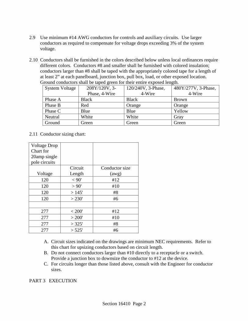
Section 16410 Page 2
2.9 Use minimum #14 AWG conductors for controls and auxiliary circuits. Use larger
conductors as required to compensate for voltage drops exceeding 3% of the system voltage.
2.10 Conductors shall be furnished in the colors described below unless local ordinances require
different colors. Conductors #8 and smaller shall be furnished with colored insulation; conductors larger than #8 shall be taped with the appropriately colored tape for a length of at least 2” at each panelboard, junction box, pull box, load, or other exposed location. Ground conductors shall be taped green for their entire exposed length.
System Voltage 208Y/120V, 3-Phase, 4-Wire
120/240V, 3-Phase, 4-Wire
480Y/277V, 3-Phase, 4-Wire
Phase A Black Black Brown Phase B Red Orange Orange Phase C Blue Blue Yellow Neutral White White Gray Ground Green Green Green
2.11 Conductor sizing chart: Voltage Drop Chart for 20amp single pole circuits
Voltage Circuit Length
Conductor size (awg)
120 < 90' #12 120 > 90' #10 120 > 145' #8 120 > 230' #6
277 < 200' #12 277 > 200' #10 277 > 325' #8 277 > 525' #6
A. Circuit sizes indicated on the drawings are minimum NEC requirements. Refer to
this chart for upsizing conductors based on circuit length. B. Do not connect conductors larger than #10 directly to a receptacle or a switch.
Provide a junction box to downsize the conductor to #12 at the device. C. For circuits longer than those listed above, consult with the Engineer for conductor
sizes. PART 3 EXECUTION
Section 16410 Page 3
3.1 Install conductors carefully using a minimum of two tradesmen – one feeding the conductors into the conduit, and the other pulling the conductors into the conduit.
3.2 Splices shall only be used for making taps in conductor runs – not for pull through conductors. Conductors shall be continuous from source to load unless specifically permitted in writing by the engineer for a particular application.
3.3 Splices shall only be made in approved enclosures. Splices shall not be pulled inside
conduits.
3.4 Each branch circuit and multiwire branch circuit shall be run with its own neutral conductor complying with NEC article 200.4.
3.5 Join stranded conductors with appropriate mechanical or compression lugs. Wire nuts may
be used for solid conductors only. Control conductors shall be terminated or spliced on appropriately labeled terminal blocks.
3.6 Provide cable supports and strain relief connectors as required by the NEC. 3.7 Furnish junction boxes, pull boxes, handholes, manholes, etc. as required to ensure that the
maximum number of bends allowed by the NEC are not exceeded and to ensure that the cables are not damaged during installation.
-- End of Section --

Section 16420 Page 1
SECTION 16420 PANELBOARDS
PART 1 GENERAL 1.1 Furnish and install all panelboards, complete with their circuit breakers, phase buses,
neutral buses, ground buses, structural supports, and other equipment necessary for complete systems.
1.2 The equipment vendor shall perform all calculations necessary and provide complete Arc
Flash Labels as required by the NFPA 70E, Standard for Electrical Safety in the Workplace and the drawings. Note: The drawings typically require more detail than required by the NFPA 70E.
PART 2 PRODUCTS 2.1 GENERAL
A. Panelboards shall be designed, manufactured, and tested to be in compliance with NEMA PB 1, UL 50, UL 67, UL 489, NFPA 70, and the ASTM.
B. Circuit breakers shall be designed, manufactured, and tested to be in compliance with
NEMA AB 1, UL 489, and Federal Specification W-C-375B/GEN.
C. Panelboards shall be UL listed for service entrance where used for that purpose. D. Panelboard ampere interrupting current (AIC) ratings shall equal the lowest rated
device in the panelboard. Provide panelboards with the AIC ratings shown on the Contract Drawings. Buses shall be braced to withstand the AIC rating shown on the drawings. Series ratings shall only be used where shown on the panelboard schedules.
E. All panelboards shall be furnished with dead-front, door-in-door construction.
F. Lug locations shall be determined during the creation of shop drawings for proper
arrangement with the raceway system.
G. Buses shall be constructed of 98% conductivity copper or equivalently rated aluminum.
H. Panelboard enclosures shall be NEMA 1 when they are to be mounted indoors, and
NEMA 3R when they are to be mounted outdoors. Provide special enclosures where shown on the Contract Drawings.
2.2 ACCEPTABLE MANUFACTURERS

Section 16420 Page 2
Panelboards shall be manufactured by Siemens, Square D, General Electric, or Cutler Hammer.
2.3 PANELBOARD CLASSES
A. Power distribution panelboards shall be available with mains and branch devices up to 1200 amperes. AIC ratings shall be available up to 200,000 Amperes. Power distribution panelboards shall be equipped with a nameplate containing the appropriate system voltage, number of wires, and number of phases for the system on which they are installed.
B. In 480Vac and less applications where a main breaker not exceeding 600 Amperes is
required, the AIC rating does not exceed 65,000 Amperes, and no branch breakers exceed 125Amperes, Square D NF and equivalent panelboards may be used.
C. In 480Vac and less applications where a main breaker not exceeding 225 Amperes is
required, the AIC rating does not exceed 14,000 Amperes, and no branch breakers exceed 100Amperes, Square D NEHB and equivalent panelboards may be used.
D. In 240Vac and less applications where a main breaker not exceeding 400 Amperes or
main lugs not exceeding 600 Amperes is required, the AIC rating does not exceed 22,000 Amperes, and no branch breakers exceed 125 Amperes, Square D NQOD and equivalent panelboards may be used.
2.4 CIRCUIT BREAKERS
A. Circuit breakers shall be thermal magnetic, molded-case with quick-make, quick-break contact action. They shall have thermal and magnetic tripping elements on each pole. Breakers with multiple poles shall have common tripping of all poles. Circuit breaker ampere ratings shall be stamped on the handle. Interrupting ratings of the circuit breakers shall be equivalent to the specified AIC rating of the panelboard. Breakers handles shall reside in a position between “ON” and “OFF” after a trip condition. Breakers shall be rated HACR when used for heating, air-conditioning, and refrigeration; HID when used with High Intensity Discharge fixtures; and shall be rated SWD when used for switching duty.
B. Circuit breaker sizes for motor loads are based on Square D recommendations for use
of their breakers at the motor horsepowers listed on the mechanical drawings. If equipment is used other than Square D, adjust breaker sizes per the manufacturer’s recommendations.
C. Circuit breakers with slash ratings, such as 120/240V or 480Y/277V, shall be used in
solidly grounded systems where the nominal voltage of any conductor to ground does not exceed the lower of the two values of the breaker’s voltage rating and the nominal voltage between any two conductors does not exceed the higher value of the circuit breaker’s voltage rating.
Section 16420 Page 3
D. Circuit breakers with straight voltage ratings, such as 240V or 480V, shall be used in
systems other than solidly grounded systems (Corner-Grounded Delta, Ungrounded, Impedance Grounded, etc.) where the nominal voltage between any two conductors does not exceed the circuit breaker’s voltage rating. A two-pole circuit breaker shall not be used to protect a three-phase, Corner-Grounded Delta system unless the circuit breaker is marked 1Ф-3Ф.
PART 3 EXECUTION 3.1 Install panelboards in complete compliance with all manufacturers’ installation
instructions. 3.2 Install conductors neatly in panelboards. Group and tie-wrap circuits that share a common
neutral. 3.3 Number circuits exactly as shown on the contract drawings.
3.4 Any panels that are floor mounted shall be provided with a 4” thick concrete housekeeping
pad that extends 1-1/2” around all edges of the panel. Provide 1”, 45 degree chamfered edges.
3.5 Where panelboards are flush-mounted, provide one 3/4” spare conduit to above the
accessible ceiling for every three available circuits not being used, but no less than two 3/4” spare conduits per panelboard.
-- End of Section --

Section 16430 Page 1
SECTION 16430 DISCONNECTS & SEPARATELY-MOUNTED CIRCUIT BREAKERS
PART 1 – GENERAL
Furnish and install all disconnects and separately mounted circuit breakers as shown on the drawings, specified herein, and required by the NEC.
PART 2 – PRODUCTS 2.1 GENERAL
A. Disconnects shall be of the heavy-duty type, and shall be UL listed for service entrance use. They shall meet or exceed the requirements of NEMA Standard KS1. Provide fuses sized to appropriately protect the load served. Equipment manufacturer’s recommendations shall take precedence over the Contract Drawings.
B. Fuses shall be dual element, time-delay, Class J fuses. They shall be Bussman Low-
Peak or approved equal.
C. Circuit breakers shall be thermal magnetic, molded-case with quick-make, quick-break contact action. They shall have thermal and magnetic tripping elements on each pole. Breakers with multiple poles shall have common tripping of all poles. Circuit breaker ampere ratings shall be stamped on the handle. Interrupting ratings of the circuit breakers shall be equivalent to the specified AIC rating of the panelboard. Breakers handles shall reside in a position between “ON” and “OFF” after a trip condition. Breakers shall be rated HACR when used for heating, air-conditioning, and refrigeration; HID when used with High Intensity Discharge fixtures; and shall be rated SWD when used for switching duty.
D. Circuit breaker sizes for motor loads are based on Square D recommendations for use
of their breakers at the motor horsepowers listed on the mechanical drawings. If equipment is used other than Square D, adjust breaker sizes per the manufacturer’s recommendations.
E. Circuit breakers with slash ratings, such as 120/240V or 480Y/277V, shall be used in
solidly grounded systems where the nominal voltage of any conductor to ground does not exceed the lower of the two values of the breaker’s voltage rating and the nominal voltage between any two conductors does not exceed the higher value of the circuit breaker’s voltage rating.
F. Circuit breakers with straight voltage ratings, such as 240V or 480V, shall be used in
systems other than solidly grounded systems (Corner-Grounded Delta, Ungrounded, Impedance Grounded, etc.) where the nominal voltage between any two conductors does not exceed the circuit breaker’s voltage rating. A two-pole circuit breaker shall

Section 16430 Page 2
not be used to protect a three-phase, Corner-Grounded Delta system unless the circuit breaker is marked 1Ф-3Ф.
G. Disconnect and individually-mounted circuit breaker ampere interrupting current
(AIC) ratings shall equal the rating of the panelboard from which they are fed unless otherwise noted.
H. Buses shall be constructed of 98% conductivity copper or equivalently rated
aluminum.
I. Switches shall be horsepower rated where used to serve motors.
J. Enclosures shall be NEMA 1 when they are to be mounted indoors, NEMA 3R when they are to be mounted outdoors, and NEMA 4X where they are subject to washdown. Provide special enclosures where shown on the Contract Drawings.
2.2 ACCEPTABLE MANUFACTURERS
Disconnects and separately-mounted circuit breakers shall be manufactured by Siemens, Square D, General Electric, or Cutler Hammer.
PART 3 EXECUTION 3.1 Install disconnects and individually-mounted circuit breakers in complete compliance with
all manufacturers’ installation instructions. Where necessary, provide structural supports and bracing for installation.
3.2 Disconnects are to be surface-mounted. 3.3 Individually-mounted circuit breakers are to be flush-mounted unless otherwise shown.
-- End of Section --
Section 16445 Page 1
SECTION 16445 TRANSFORMERS
PART 1 GENERAL
Provide all equipment, labor, and materials required for complete and operable installation of transformers as shown on the drawings and specified herein.
PART 2 PRODUCTS 2.1 Transformers 1000 KVA and smaller shall be listed by UL. They shall conform to the
requirements of ANSI/NFPA 70. They are to be manufactured and tested in accordance with NEMA ST20.
2.2 Transformers shall be designed for operation at 60 Hz. The transformer furnished for this
project shall contain a 208 volt delta-connected primary and a 480Y277 volt wye connected secondary.
2.3 All insulating materials shall exceed NEMA ST20 standards and be rated for 220 degrees
Celsius according to UL’s component recognized insulation system. 2.4 Transformers 15 KVA and larger shall be rated for 150 degrees C temperature rise above
an ambient temperature of 40 degrees C. Transformers 25 KVA and above shall have four 2.5% full capacity primary taps (two above and two below).
2.5 The maximum temperature of the top of the enclosure shall not exceed 50 degrees C above
an ambient temperature of 40 degrees C. 2.6 Furnish transformers located outside with factory-furnished weatherproof enclosures. 2.7 Transformer coils shall be of continuous wound construction. 2.8 Transformer cores are to be visibly grounded to the enclosure by means of a flexible
grounding conductor sized in accordance with applicable UL and NEC standards. 2.9 Transformers shall be ventilated and fabricated of heavy gauge sheet steel. The entire
enclosure shall be finished utilizing a continuous process of degreasing, cleaning and phosphatizing, followed by electrostatic deposition of polymer polyester powder coating and baking to provide a uniform coating of all edges and surfaces.
2.10 Sound levels shall be warranted by the manufacturer not to exceed the following:
• 15 to 50 KVA – 45 dB • 51 to 150 KVA – 50 dB • 151 to 300 KVA – 55 dB • 301 to 500 KVA – 60 dB • 501 to 700 KVA – 62 dB
Section 16445 Page 2
• 701 to 1000 KVA – 64 dB • 1001 to 1500 KVA – 65 dB • 1501 to 2000 KVA – 66 dB
PART 3 EXECUTION 3.1 Install transformers in strict compliance with the manufacturer’s instructions and the latest
version of the National Electrical Code. 3.2 Provide concrete housekeeping pads for transformers mounted indoors. Housekeeping
pads shall consist of 3.5” thick pads containing #4 reinforcing bars on 6” centers in both horizontal directions in the center of 3000 psi concrete. Where transformers are located outside, the pad shall extend at least 6” above grade and shall have a 12” wide footing at least 4” below the frost line; the footing shall be a minimum of 12” deep.
3.3 Transformers not exceeding 75 KVA may be wall-mounted where sufficient proof is
provided that the structure can support the weight and where factory-provided wall brackets are used.
-- End of Section --
Section 16460 Page 1
SECTION 16460 SWITCHES AND RECEPTACLES
PART 1 GENERAL Furnish and install all switches and receptacles in accordance with this specification and the requirements of the NEC. PART 2 PRODUCTS 2.1 ACCEPTABLE MANUFACTURERS Switches and receptacles shall be manufactured by Hubbell, Cooper Wiring Devices, Leviton, or Pass & Seymour. 2.2 GENERAL
A. Switches and receptacles shall be specification grade. They shall have ampacity and voltage ratings suitable for the application in which they are used.
B. Consult architect or engineer for device colors prior to ordering devices.
C. Provide brushed stainless steel cover plates for all devices. A single cover plate shall
cover all devices in one box.
D. Light switches shall be 20 Ampere, 120-277V back-wired and side-wired toggle switches. They shall be rated up to 2 HP at 240V. Each switch shall be equipped with a grounding screw. Switches shall be Hubbell CSB series or approved equal.
E. Duplex NEMA 5-20R receptacles shall be Hubbell HBL 5362A or approved equal.
F. Duplex GFI NEMA 5-20R receptacles shall be Hubbell HBL GF5362A or approved
equal.
G. Weatherproof while-in-use cover plates shall be Teddico #34017-7 or approved equal. Cover plates shall be single gang, lockable, and constructed of heavy duty die cast metal.
H. All 125V, 15 and 20 ampere receptacles installed in dwelling units shall be of the
tamper-resistant type.
I. All 15 and 20 ampere, 125 and 250V non-locking receptacles installed in wet or damp locations shall be listed as the weather-resistant type.
J. Devices furnished in this Contract, but not listed above, shall be of the same standard
of quality as those items listed.
Section 16460 Page 2
PART 3 EXECUTION 3.1 Flush mount all devices unless specific written permission is obtained from the Engineer
for a particular device in a particular location. 3.2 Install all devices vertically unless the drawings specifically state that the particular device
should be mounted horizontally.
3.3 Install receptacles by utilizing pigtails. Do not install receptacles in a “feed thru” fashion. 3.4 Install receptacles with the ground slot up.
-- End of Section --
Section 16470 Page 1
SECTION 16470 ELECTRICAL STUDIES
PART 1 GENERAL 1.1 The Electrical Studies in this specification shall be performed by the electrical gear
Manufacturer. The Electrical Studies shall be preliminarily performed at the electrical gear submittal time and then updated when all of the electrical gear is installed and the exact electrical parameters are known.
1.2 The purpose of the preliminary study (Fault Current Study) is to verify that the electrical gear is specified with the correct AIC ratings for the facilities’ power system. The initial study shall be conducted using the electrical gear specified in the construction documents. The Single Line Diagram in the construction drawings shall be used for circuitry sizes of the major electrical gear. The Power, Mechanical, and Equipment Plans in the construction drawings shall be used for circuitry sizes of the remaining electrical gear. The Utility transformer shall be modeled using “worst case” parameters for impedance and infinite short circuit current available at the primary of the transformer. Dry type transformers shall be modeled using typical impedances for the size of transformer specified. Emergency generators shall be modeled using “worst case” parameters for sub-transient reactance and a typical decrement curve for the kW size of generator specified utilizing a permanent magnet alternator. The Electrical Contractor shall assist the electrical gear Manufacturer’s Engineer with estimated circuitry lengths. The studies shall be run, evaluated, and then submitted along with the electrical gear submittals. The equipment AIC ratings on the Drawings and in the Specifications represent the minimum acceptable ratings. Higher rated equipment shall be provided as necessary, based on study results. Electrical gear submittals will not be approved without the results of this study. An electronic copy of the power system model shall be saved by the electrical gear Manufacturer’s Engineer.
1.3 After all of the electrical gear is installed and the exact electrical parameters of the project are known, the Electrical Contractor shall give that information to the electrical gear Manufacturer’s Engineer. The saved power system model shall be updated with the exact utility X/R ratios (three phase and phase-to-ground), utility primary voltage over-current protection devices, transformer impedances, circuitry sizes, circuitry lengths, generator sub-transient reactance, and generator overload curves. The purpose of updating the preliminary power system model is to provide accurate information for Arc Flash Labels, Available Fault Current Labels, and Protective Device Settings. A Fault Current Study, a Protective Device Coordination Study, and an Arc Flash Study shall be run, evaluated, and then submitted to the electrical engineer for approval. The approved study report shall be used for setting the Protective Devices, producing Arc Flash Labels, and producing Available Fault Current Labels.
PART 2 ELECTRICAL STUDIES PERFORMED 2.1 PROTECTIVE DEVICE COORDINATION AND ARC FLASH STUDIES
Section 16470 Page 2
A. The Contractor shall employ the equipment Manufacturer’s Engineers to perform the Protective Device Coordination and Arc Flash studies. The Engineer responsible for the study shall perform such work as his job responsibility, and shall have performed at least 100 such studies in his career. Submit the Engineer’s credentials with the study results.
B. Analyses shall be prepared to demonstrate that the equipment and system to be
provided meet the specified requirements for equipment ratings, coordination, and protection. They shall include a fault current analysis and protective device coordination study.
C. Scope of Analyses. The Fault Current Analysis, Protective Device Coordination, and
Arc Flash Studies shall include all electrical equipment where the incident energy level is greater than 1.2 Cal/cm^2. The term electrical gear shall include the following: Transformers (Utility & Dry Type), Switchboards, Panelboards, Motor Control Centers, Disconnects, Loadcenters, Enclosed Circuit Breakers, Motor Starters, Contactors, etc.
D. Determination of Facts. The time-current characteristics, features, and nameplate
data for each existing protective device shall be determined and documented. The Contractor shall coordinate with the commercial power company for three phase and single phase fault current availability and X/R ratios at the site.
E. Single-Line Diagram. Provide a single-line diagram to show the electrical system
buses, devices, transformation points, and all sources of fault current (including generator and motor contributions). A fault-impedance diagram or a computer analysis diagram shall be provided. Each bus, device or transformation point shall have a unique identifier. If a fault-impedance diagram is provided, impedance data shall be shown. Locations of switches, breakers, and circuit interrupting devices shall be shown on the diagram, together with available fault data, and the device interrupting rating.
F. Arc Flash Hazard Analysis:
1. Method. The Arc Flash Hazard analysis shall be performed in accordance with the latest applicable NFPA 70E, OSHA 29-CFR, Part 1910 Sub part S, IEEE 1584, and NESC Standards. The study must be performed using IEEE 1584 for equipment rated 50 to 15kV and NESC for equipment rated above 15kV. The use of NFPA 70E Task Tables to determine Hazard Classification is not acceptable.
2. Data. The analysis shall consider all operating scenarios during normal
conditions, alternate operations, emergency power conditions, and any other operations, which could result in maximum Arc Flash Hazard. The label shall list the maximum incidental energy calculated and the scenario. Possible scenarios include, but are not limited to: Normal Utility Power, Emergency Generator Power, Bus Tie Breaker Open, Bus Tie Breaker Closed, UPS Power, etc..
Section 16470 Page 3
G. Fault Current Analysis:
1. Method. The fault current analysis shall be performed in accordance with methods described in IEEE Std 242, and IEEE Std 399.
2. Data. Actual data shall be utilized in final fault calculations. Bus characteristics
and transformer impedances shall be those proposed for the initial analysis. Data shall be documented in the report.
G. Fault Current Availability. Balanced three-phase fault, bolted line-to-line fault, and
line-to-ground fault current values shall be provided at each voltage transformation point and at each power distribution bus. This data shall be shown in tabular form on the diagram or in the report.
H. Coordination Study. The study shall demonstrate that the maximum possible degree
of selectivity has been obtained between all electrical equipment, consistent with protection of equipment and conductors from damage from overloads and fault conditions. The study shall include a description of the coordination of the protective devices in this project. Provide a written narrative that describes: which devices may operate in the event of a fault at each bus; the logic used to arrive at device ratings and settings; any situations where system coordination is not achievable due to device limitations (an analysis of any device curves which overlap); coordination between upstream and downstream devices; and settings. Provide recommendations to improve or enhance system reliability and detail where such changes would involve additions or modifications to the Contract. Cost changes (addition or reduction) shall be provided. Composite coordination plots shall be provided on log-log graph paper.
I. Study Reports (Initial and Final)
1. The reports shall include a narrative: the analyses performed; the bases and methods used; and the desired method of coordinated protection of the power system.
2. The reports shall include descriptive and technical data for existing devices and
new protective devices proposed. The data shall include Manufacturer’s published data, nameplate data, and definition of the fixed or adjustable features of the existing or new protective devices.
3. The reports shall document utility company data including system voltages, fault
MVA, system three phase X/R ratio and magnitude, system single line to ground X/R ratio and magnitude, time-current characteristic curves, current transformer ratios, relay device curves, and protective device ratings & settings.
4. The reports shall contain fully coordinated composite time-current characteristic
curves for each bus in the system as required to ensure coordinated power system
Section 16470 Page 4
protection between protective devices or equipment. The report shall include recommended devices or equipment. The report shall include recommended ratings and settings of all protective devices in tabulated form.
5. The reports shall provide the calculations performed for the analyses including
computer analysis programs utilized. The name of the software package, developer, and version number shall be provided.
PART 3 LABELS
3.1 The Electrical Gear Manufacturer shall print Arc Flash Labels for all electrical gear
[Switchboards, Panelboards, Transformers (all except Utility), Motor Control Centers, Disconnects, Loadcenters, Enclosed Circuit Breakers, Motor Starters, Contactors, etc.] complying with the label detail in the construction drawings. The labels shall be of a type and quality to last in the environment in which they are installed. The labels shall be furnished to the Electrical Contractor for installation.
3.2 The Electrical Contractor shall make the Available Fault Current Labels complying with the label detail in the construction drawings for each piece of electrical gear. The Protective Device Coordination Study report shall be used for providing the Available Fault Current at each location. The labels shall comply with NEC Article 110.24 of the 2011 edition. Available Fault Current labels shall be of a type and quality to last in the environment in which they are installed. The labels shall be mounted according to the label detail in the construction drawings.
-- End of Section --
Section 16490 Page 1
SECTION 16490 SURGE PROTECTIVE DEVICES (SPDs)LOW VOLTAGE AC SURGE PROTECTION FOR
ELECTRICAL DISTRIBUTION SYSTEMS PART 1 GENERAL 1.1 RELATED DOCUMENTS
A. Drawings and general provisions of the Contract, including General and Supplementary Conditions and Divisions 1 Specification sections apply to this section.
1.2 RELATED WORK SPECIFIED ELSEWHERE:
A. General electrical requirements. B. Raceways, boxes and fittings. C. Wire and cable. D. Low voltage motor control. E. Variable frequency drives. F. Grounding. G. Lightning protection systems.
1.3 DESCRIPTION
A. Surge Protection Device (SPD) is the description and equipment required for the protection of all AC electrical circuits and electronic equipment from the effects of lightning induced voltages, external switching transients and internally generated switching transients.
1.4 REFERERENCE STANDARDS AND PUBLICATIONS
A. The latest edition of the following standards and publications shall comply to the work of this section:
1. ANSI/IEEE C84.1-1989, American National Standard for Electric Power Systems
and Equipment - Voltage Ratings (60 Hertz) 2. ANSI/IEEE C62.41.1-2002, Guide on the Surge Environment in Low-Voltage AC
Power Circuits 3. ANSI/IEEE C62.41.2-2002, Recommended Practice on Characterization of Surges
in Low-Voltage AC Power Circuits
Section 16490 Page 2
4. ANSI/IEEE C62.45-2002, IEEE Recommended Practice on Surge Testing for Equipment Connected to Low-Voltage AC Power Circuits
5. Underwriters Laboratories UL 1449 Third Edition, Standard for Safety – Surge Suppression Devices
6. Underwriters Laboratories, UL 1283, Standard for Safety - Electromagnetic Interference Filters
7. National Fire Protection Association, NFPA 780 - National Electrical Code 8. IEEE Standard 142-1991, IEEE Recommended Practice for Grounding of
Industrial and Commercial Power Systems (IEEE Green Book) 9. ANSI/IEEE Standard 141-1999, IEEE Recommended Practice for Electric Power
Distribution for Industrial Plants (IEEE Red Book) 10. IEEE Standard 1100-1999, IEEE Recommended Practice for Powering and
Grounding Sensitive Electronic Equipment (IEEE Emerald Book) 11. FIPS Pub 94, Federal Information Processing Standards Publication - Guideline on
Electrical Power for ADP Installations 12. National Electrical Manufacturer’s Association LS-1, 1992 (NEMA LS-1) 13. MIL Standard 220A Method of Insertion-loss Measurement 14. ISO 9001:2000, Quality Systems - Model for Quality Assurance in Design,
Development, Production, Installation and Servicing 1.5 MANUFACTURER QUALIFICATIONS
A. Advanced Protection Technologies (APT) shall be the basis of design. All products submitted shall comply with the specifications of the APT model type specified herein.
B. The manufacturer shall specialize only in SPD and shall have a minimum of 10 years
experience in manufacturing SPD. C. The manufacturer shall submit a written statement indicating that a factory authorized
representative inspected the installation. The installing contractor shall submit a checkout memorandum to the manufacturer. The memorandum shall indicate the date the equipment is placed into service and the actual method of installation. Submit three copies to the specifying engineer.
1.6 WARRANTY
A. The SPD and supporting components shall be guaranteed by the manufacturer to be free
of defects in material and workmanship for a minimum period of 20 years from the date of substantial completion of service and activation of the system to which the suppressor is attached.
Section 16490 Page 3
B. An SPD that shows evidence of failure or incorrect operation during the warranty period shall be replaced free of charge. Since “Acts of Nature” or similar statements typically include the threat of lightning to which the SPD’s shall be exposed, any such clause limiting warranty responsibility in the "General Conditions" section of this specification shall not apply to this section. The warranty shall cover the entire device.
C. The installation of SPD’s in or on electrical distribution equipment shall in no way
compromise or violate equipment listing, labeling, or warranty of the distribution equipment.
1.7 SUBMITTALS
A. The Surge Suppression Device submittals shall include, but shall not be limited to, the
following information: 1. Data for each suppressor type indicating conductor sizes, conductor types and
connection configuration and lead lengths. 2. Manufacturer’s certified test data indicating the ability of the product to meet or
exceed requirements of this specification. 3. Suppressor manufacturer shall provide certified test data confirming Short Circuit
Current Rating (SCCR) of the SPD(s).
4. UL 1449 clamp voltage documentation 5. Drawings, with dimensions, indicating SPD mounting arrangement and lead length
configuration, and mounting arrangement of any optional remote diagnostic equipment and assemblies.
6. List and detail all protection systems such as fuses, disconnecting means and
protective materials.
7. SPD wiring, bonding and grounding connections shall be indicated on the wiring diagrams for each system. Include installation details demonstrating mechanical and electrical connections to equipment to be protected.
8. If requested, a sample of each suppressor type shall be submitted for use in testing
and evaluation.
PART 2 PRODUCTS
2.1 Accepted Manufacturers Advanced Protection Technologies (APT)
Section 16490 Page 4
Eaton Innovative Technology Schneider Electric PERFORMANCE
A. GENERAL
1. SPD’s shall be listed in accordance with UL 1449 Third Edition, Standard for Safety, Surge Protective Devices and UL 1283, Standard for Safety, Electromagnetic Interference Filters.
2. The SPD shall protect all modes:
a. A three-phase, four-wire plus ground (wye) voltage system shall have seven discrete suppression circuits: 3-modes (Line-to-Ground), 3-modes (Line-to-Neutral) and 1-mode (Neutral-to-Ground). Line-to-Neutral-to-Ground is not an acceptable substitute for Line-to-Ground.
b. A three-phase, 3-wire plus ground (delta) voltage system shall have six discrete modes of protection: 3-modes (Line-to-Neutral) and 3-modes (Line-to-Ground).
c. A three-phase, 4-wire plus ground (high-leg delta) voltage system shall have seven discrete modes of protection: 3-modes (Line-to-Ground), 3-modes (Line-to-Neutral) and 1-mode (Neutral-to-Ground).
3. SPD’s shall use a separate path to building ground; the equipment safety ground is
not to be used as a transient ground path.
4. SPD’s shall have a SCCR of 200kA. Fuse ratings shall not be considered in lieu of demonstrated withstand testing of SPD, per NEC 285.6.
5. SPD shall be UL labeled with 20kA I-nominal (I-n) (verifiable at UL.com) for compliance to UL 96A Lightning Protection Master Label and NFPA 780.
6. The SPD circuit construction of the main surge current diversion path shall be MOV (metal-oxide varistors) based. The protection status of device shall be clearly monitored on the front panel of the SPD enclosure.
7. Each SPD shall be provided with a protective disconnecting means in accordance
with code requirements.
a) Where SPDs are being furnished for new panels, an integral disconnect switch shall be used, and the SPD shall be directly connected to the panelboard bus.
b) Where SPDs are being furnished for existing panels, a 30A, 3-pole circuit breaker shall be installed in the panelboard to serve the SPD (adjust breaker
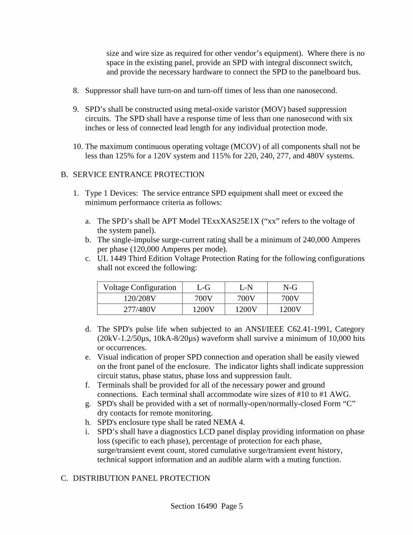
Section 16490 Page 5
size and wire size as required for other vendor’s equipment). Where there is no space in the existing panel, provide an SPD with integral disconnect switch, and provide the necessary hardware to connect the SPD to the panelboard bus.
8. Suppressor shall have turn-on and turn-off times of less than one nanosecond.
9. SPD’s shall be constructed using metal-oxide varistor (MOV) based suppression circuits. The SPD shall have a response time of less than one nanosecond with six inches or less of connected lead length for any individual protection mode.
10. The maximum continuous operating voltage (MCOV) of all components shall not be
less than 125% for a 120V system and 115% for 220, 240, 277, and 480V systems.
B. SERVICE ENTRANCE PROTECTION 1. Type 1 Devices: The service entrance SPD equipment shall meet or exceed the
minimum performance criteria as follows:
a. The SPD’s shall be APT Model TExxXAS25E1X (“xx” refers to the voltage of the system panel).
b. The single-impulse surge-current rating shall be a minimum of 240,000 Amperes per phase (120,000 Amperes per mode).
c. UL 1449 Third Edition Voltage Protection Rating for the following configurations shall not exceed the following:
Voltage Configuration L-G L-N N-G
120/208V 700V 700V 700V 277/480V 1200V 1200V 1200V
d. The SPD's pulse life when subjected to an ANSI/IEEE C62.41-1991, Category
(20kV-1.2/50µs, 10kA-8/20µs) waveform shall survive a minimum of 10,000 hits or occurrences.
e. Visual indication of proper SPD connection and operation shall be easily viewed on the front panel of the enclosure. The indicator lights shall indicate suppression circuit status, phase status, phase loss and suppression fault.
f. Terminals shall be provided for all of the necessary power and ground connections. Each terminal shall accommodate wire sizes of #10 to #1 AWG.
g. SPD's shall be provided with a set of normally-open/normally-closed Form “C” dry contacts for remote monitoring.
h. SPD's enclosure type shall be rated NEMA 4. i. SPD’s shall have a diagnostics LCD panel display providing information on phase
loss (specific to each phase), percentage of protection for each phase, surge/transient event count, stored cumulative surge/transient event history, technical support information and an audible alarm with a muting function.
C. DISTRIBUTION PANEL PROTECTION
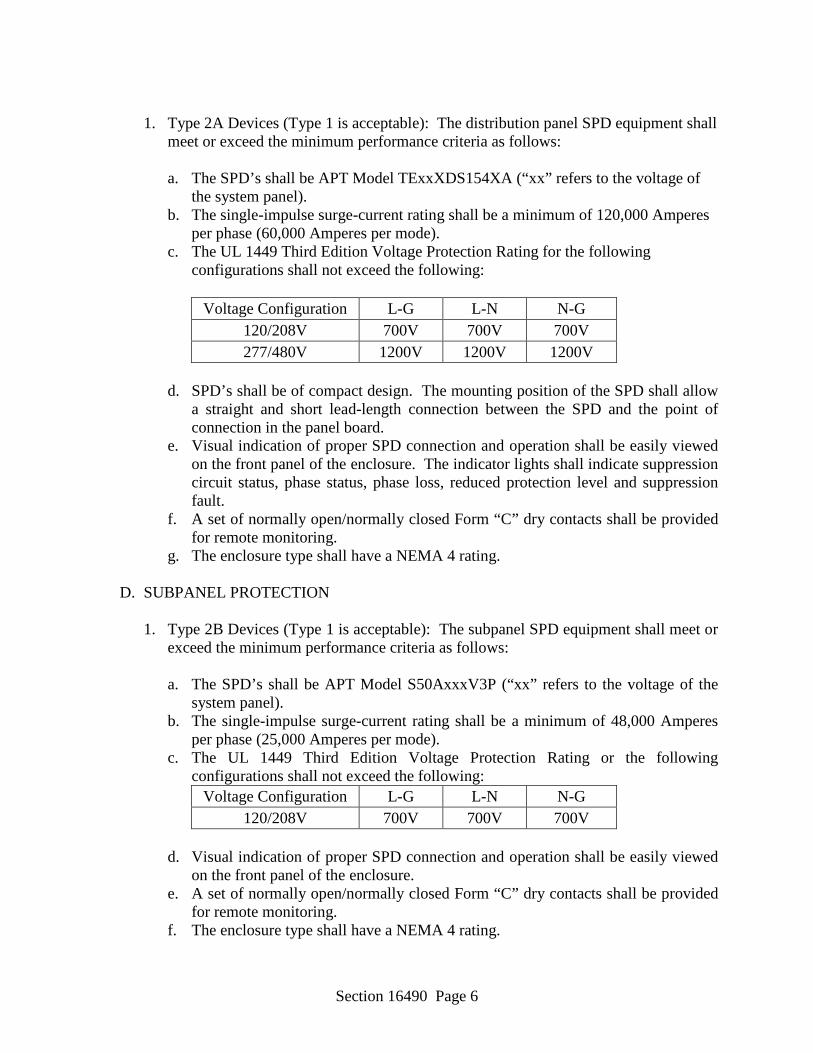
Section 16490 Page 6
1. Type 2A Devices (Type 1 is acceptable): The distribution panel SPD equipment shall
meet or exceed the minimum performance criteria as follows:
a. The SPD’s shall be APT Model TExxXDS154XA (“xx” refers to the voltage of the system panel).
b. The single-impulse surge-current rating shall be a minimum of 120,000 Amperes per phase (60,000 Amperes per mode).
c. The UL 1449 Third Edition Voltage Protection Rating for the following configurations shall not exceed the following:
Voltage Configuration L-G L-N N-G
120/208V 700V 700V 700V 277/480V 1200V 1200V 1200V
d. SPD’s shall be of compact design. The mounting position of the SPD shall allow
a straight and short lead-length connection between the SPD and the point of connection in the panel board.
e. Visual indication of proper SPD connection and operation shall be easily viewed on the front panel of the enclosure. The indicator lights shall indicate suppression circuit status, phase status, phase loss, reduced protection level and suppression fault.
f. A set of normally open/normally closed Form “C” dry contacts shall be provided for remote monitoring.
g. The enclosure type shall have a NEMA 4 rating. D. SUBPANEL PROTECTION
1. Type 2B Devices (Type 1 is acceptable): The subpanel SPD equipment shall meet or exceed the minimum performance criteria as follows:
a. The SPD’s shall be APT Model S50AxxxV3P (“xx” refers to the voltage of the
system panel). b. The single-impulse surge-current rating shall be a minimum of 48,000 Amperes
per phase (25,000 Amperes per mode). c. The UL 1449 Third Edition Voltage Protection Rating or the following
configurations shall not exceed the following: Voltage Configuration L-G L-N N-G
120/208V 700V 700V 700V d. Visual indication of proper SPD connection and operation shall be easily viewed
on the front panel of the enclosure. e. A set of normally open/normally closed Form “C” dry contacts shall be provided
for remote monitoring. f. The enclosure type shall have a NEMA 4 rating.
Section 16490 Page 7
F. POINT-OF-USE SINGLE-PHASE (120 VAC) HARD-WIRED SUPPRESSORS
1. Type 3 Devices (Type 1 is acceptable): The subpanel SPD equipment shall meet or
exceed the minimum performance criteria as follows:
a. The SPD’s shall be APT Model S50A120V1P. b. The single-impulse surge-current rating shall be a minimum of 40,000 Amperes
per phase (20,000 Amperes per mode). c. A single-phase, two-wire plus ground voltage system shall have three discrete
suppression circuits: 1-mode (Line-to-Ground), 1-mode (Line-to-Neutral) and 1-mode (Neutral-to-Ground). Line-to-Neutral-to-Ground is not an acceptable substitute for Line-to-Ground.
d. Suppressors shall be listed in accordance with UL 1449 3RD Edition, Standard for Safety, Transient Voltage Surge Suppressors. The SPD's UL 1449 Third Edition Voltage Protection Rating shall not exceed 700 volts peak.
e. The SPD's pulse life when subjected to an ANSI/IEEE C62.41-1991, Category B3/C1 (6 kV - 1.2/50 µs, 3 kA - 8/20 µs) waveform once every 30 seconds shall survive a minimum of 3000 hits or occurrences.
f. Visual indication of proper connection and operation shall be provided conveniently on the enclosure of the SPD.
g. SPD(s) shall provide fusing in such a manner that the power to the load is not interrupted.
PART 3 EXECUTION 3.1 GENERAL
A. The contractor shall follow the SPD manufacturer’s recommended installation practice as
found in the equipment installation instructions. B. SPD’s shall be of compact design. The mounting position of the SPD shall allow a
straight and short lead-length connection between the SPD and the point of connection in the panelboard.
C. The installing contractor shall install the parallel SPD with short and straight conductors as practically possible.
D. Installer may reasonably rearrange breaker locations to ensure short and straightest
possible leads to SPD’s. E. The installation shall apply to all applicable codes.
3.2 SERVICE ENTRANCE PROTECTION
Section 16490 Page 8
A. Install one SPD at each utility service entrance location whether indicated on the drawings or not.
B. The SPD's ground shall be bonded to the service entrance ground.
C. Neutral and ground shall be bonded together at service entrance panel locations.
3.3 DISTRIBUTION PANEL PROTECTION
A. Install one SPD at each utility distribution panel location whether indicated on the drawings or not.
B. Neutral and ground shall not be bonded together inside any distribution panel location.
3.4 SUBPANEL PROTECTION
A. Install one SPD at each utility subpanel location where indicated on the drawings. B. Neutral and ground shall not be bonded together inside any subpanel location.
3.4 ELECTRONIC EQUIPMENT AC POWER SUPPLY POINT-OF-USE (120VAC) HARD-
WIRED PROTECTION A. Install one each point-of-use (120VAC) hard-wired SPD between each equipment item
and its power supply conductors as follows:
a. Fire alarm master panel b. Intercom master c. Building energy management system master d. Security system master e. Telephone system switch f. TV head end
B. Install SPD's according to manufacturer's installation instructions.
-- End of Section --
Section 16500 Page 1
SECTION 16500 LIGHTING
PART 1 GENERAL 1.1 Provide all lighting fixtures (luminaires), lamps, end caps, connectors, fittings, structural
support members, supports, brackets, etc., for a complete and operable lighting system. PART 2 SUBMITTALS 2.1 SHOP DRAWINGS
A. Indicate dimensions and components for each luminaire that is not a standard product
of the manufacturer. B. Provide photometric calculations where luminaires are proposed for substitution. C. Product Data: Provide manufacturer's standard catalog pages and data sheets
including detailed information on construction, dimensions, ratings, finishes, mounting requirements, listings, service conditions, and installed accessories; include model number nomenclature clearly marked with all proposed features.
2.2 Certificates for Dimming Ballasts: Manufacturer's documentation of compatibility with
dimming controls to be installed. 2.3 Manufacturer's Installation Instructions: Indicate application conditions and limitations of
use stipulated by product testing agency. Include instructions for storage, handling, protection, examination, preparation, and installation of product.
2.4 Operation and Maintenance Data: Instructions for each product including information on
replacement parts. 2.5 Warranty: Submit sample of manufacturer's warranty and documentation of final executed
warranty completed in Owner's name and registered with manufacturer. 2.6 Project Record Documents: Record actual connections and locations of luminaires and any
associated remote components.
PART 3 PRODUCTS 3.1 DELIVERY, STORAGE, AND PROTECTION
A. Receive, handle, and store products according to NECA/IESNA 500 and
manufacturer's written instructions.
Section 16500 Page 2
B. Keep products in original manufacturer's packaging and protect from damage until ready for installation.
3.2 LUMINAIRES
A. Luminaires are shown in the Luminaire Schedule on the drawings to establish a standard of quality. Manufacturer’s names and model numbers shall not be interpreted as a proprietary specification. Notify the engineer at least two weeks prior to bid if an equivalent for a fixture listed in the schedule is not readily available.
B. Prior to submitting electrical equipment brochures for review and approval,
coordinate with the General Contractor and verify that the fixtures are appropriate for the ceiling types in which they are shown to be installed. Also verify that the voltage on the submittals is appropriate for the electrical system on which the fixtures are to be installed (regardless of voltage listed in the part number in the Fixture Schedule). Submit with equipment brochures a certificate stating that these items of coordination have been completed.
C. Coordinate the work to provide ballasts/drivers compatible with the lighting controls
to be installed. D. Color samples for fixture finishes shall be submitted upon request to the Architect for
approval prior to ordering fixtures. E. Emergency Power Supply Units: Suitable for use with indicated luminaires,
complying with NFPA 101, all applicable state and local codes, and listed and labeled as complying with UL 924.
3.3 LAMPS
A. T8 fluorescent lamps shall be rapid-start with a Color Rendering Index (CRI) of 75
and a color temperature of 3500K. B. T5 & T5HO fluorescent lamps shall be rapid-start with a Color Rendering Index
(CRI) of 82 and a color temperature of 3500K. C. HID Lamps shall be clear unless otherwise noted. They shall have a color
temperature of 3500K. Coordinate base size with fixture socket prior to ordering lamps.
D. LED lamps shall be LM79 and LM80 tested.
3.4 LED DRIVERS
A. General Requirements:

Section 16500 Page 3
1. Operate for at least 50,000 hours at maximum case temperature and 90 percent non-condensing relative humidity.
2. Provide thermal fold-back protection by automatically reducing power output
(dimming) to protect LED driver and LED light engine/fixture from damage due to over-temperature conditions that approach or exceed the LED driver's maximum operating temperature at calibration point.
3. UL 8750 recognized or listed as applicable. 4. Class A sound rating; Inaudible in a 27 dBA ambient. 5. Demonstrate no visible change in light output with a variation of plus or minus 10
percent change in line-voltage input. 6. LED drivers of the same family/series to track evenly across multiple fixtures at
all light levels. 7. Offer programmable output currents in 10 mA increments within designed driver
operating ranges for custom fixture length and lumen output configurations, while meeting a low-end dimming range of 100 to 1 percent or 100 to 5 percent as applicable.
8. Employ integral fault protection up to 277 V to prevent LED driver damage or
failure in the event of incorrect application of line-voltage to communication link inputs.
9. LED driver may be remote located up to 100 feet (30 m) from LED light engine
depending on power outputs required and wire gauge utilized by installer.
B. Driver Control:
1. Provide integral fault protection to prevent driver failure in the event of a mis-wire.
2. Operate from input voltage of 120 V through 277 V at 50/60 Hz. 3. Drivers and their associated controls shall be coordinated to ensure they are
compatible. 3.5 BALLASTS
A. Fluorescent luminaires shall be furnished with energy-saving, high power factor (0.9
or greater), electronic ballasts. Ballasts shall operate lamps without noticeable flicker and shall operate within the IES recommended noise levels. Ballasts shall operate at a frequency no less than 20,000 Hz. Total harmonic distortion shall be less than 10%.
Section 16500 Page 4
Ballasts shall be able to withstand voltage transients in accordance with IEEE C62.41, Category A for normal and common modes. Ballasts shall be compatible with the lamps furnished. Furnish number and size of ballasts as required to operate the number of lamps indicated with the control schemes shown.
B. Fluorescent ballasts for light fixtures controlled by occupancy sensors shall be programmed start ballasts with the lamps wired in parallel. Failure of one lamp shall leave the rest of the lamps illuminated.
C. Emergency Battery Packs: Emergency Battery Packs in fixtures shall consist of an automatic power failure device and a test switch. They shall contain a fully automatic solid state charger in a self-contained power pack. Wiring Diagrams shall be furnished with the fixture showing switching connections. The battery shall be of the sealed electrolyte type with the capacity to provide power to the lamps provided for a minimum of 90 minutes at an 1100 lumens.
The battery shall be able to operate unattended with no maintenance for a period of no less than five years. Emergency ballasts shall be fully compatible with solid state ballasts. Battery packs shall be mounted inside the fixture unless remotely mounted ballasts are shown on the drawings, or unless the fixture is of a type that does not have room for internally mounted battery packs.
D. Where quartz restrike fixtures are fed at voltages different than 120V, they shall be
furnished with integral transformers and all equipment necessary to feed the quartz fixtures at 120V.
3.6 SUPPORTS
A. Provide all structural members necessary to support fixtures in locations shown on the
contract drawings. Submit mounting and support details to the Architect or Engineer for approval with the project shop drawings. Notify the General Contractor prior to bid of any structural work that will be required to support the fixtures.
B. Provide hangers, cords, stems, etc., where required. Coordinate with the Architect or
Engineer for proper stem lengths prior to ordering fixtures. C. Support the ceiling grid at all four corners of recessed light fixtures. D. Provide clips for fixtures installed in lay-in ceilings. Clips shall be equal to Erico
Caddy clips # 515 or #515A.
-- End of Section --
Section 16510 Page 1
SECTION 16510 OCCUPANCY SENSORS
PART 1 GENERAL 1.1 Furnish and install a complete system of Occupancy sensors as shown on the drawings and as
specified herein. The drawings are provided to show the general scope of the work, and show the absolute minimum components required. Actual system components, quantities, and locations shall be determined by the motion detector vendor and provided to the Contractor with the installation shop drawings.
1.2 The Contractor and Sales Representatives are advised to take notice of specified component
characteristics when attempting to select and propose substitutions. It is highly unlikely that substitutions on a one-for-one component basis will produce results that provide acceptable system performance.
1.3 Provide all power packs, hardware, software, devices, circuitry, and other components,
material, and labor required to install, configure, and test the entire system to the satisfaction of the Architect, Owner, and Engineer.
1.4 Submit six sets of manufacturer’s cut sheets describing completely all equipment, and six sets
of shop drawings showing all circuitry including terminal-to-terminal connections.
1.5 The wiring diagrams on these drawings are based on our best interpretation of the manufacturer’s data that was available at the time of design; however, they shall not be used for system installation and configuration. The controls equipment vendor is expected to be thoroughly knowledgeable of the equipment that is being proposed, and shall provide detailed shop drawings tailored for each circuit and lighting zone on the project. General manufacturer’s data sheets shall not be acceptable. The shop drawings shall be suitable for the installing electrician to use for complete installation of the circuitry without referring to data sheets or installation manuals for connection of lighting control equipment. These requirements shall be followed whether the specified equipment, or products of other manufacturers, is provided.
PART 2 PRODUCTS 2.1 Hallway Occupancy sensors: Occupancy sensors used in the hallways shall be passive infrared,
ceiling-mounted units with a coverage of 6’ x 130’. They shall be Sensor Switch HW13 WV BR or approved equal.
2.2 Areas up to 500 Square Feet: Occupancy sensors used in areas up to 500 square feet shall be
dual technology infrared and microphonics, ceiling-mounted units with a 360 degree, 500 square foot coverage. They shall Sensor Switch CM PDT 9 or approved equal.
2.3 Areas up to 2000 Square Feet: Occupancy sensors used in areas up to 2000 square feet shall be
Section 16510 Page 2
dual technology infrared and microphonics, ceiling-mounted units with a 360 degree, 2000 square foot coverage. They shall be Sensor Switch CM PDT 10 or approved equal.
2.4 Power Packs: Power packs shall be of the same manufacturer as the occupancy sensors. Each
shall be capable of controlling a 20 ampere circuit. They shall be rated for operation at the voltage of the system on which they will be used.
2.5 Circuitry: Provide control circuitry as required by the manufacturer for optimum system
operation, but no less than the following: Control cables shall be 3-conductor #22 AWG copper with an overall jacket. Adjust conductor sizes as required to overcome unacceptable voltage drop.
PART 3 EXECUTION 3.1 Occupancy sensors shall be provided so that their coverage areas overlap and there are no dead
zones in the rooms where persons may stand and not be detected. 3.2 All work shall be done by qualified system technicians. 3.3 Wiring, including control wiring, shall be in Raceways meeting Specification 16110. 3.4 Guarantee workmanship and material for a period of one year after final acceptance. During
the warranty period, repair or replace faulty equipment at no cost to the Owner for labor, material, or expenses.
3.5 Upon completion of job, test entire system. After testing submit a certificate to the Architect
stating verification of the following: PART 4 CLOSE-OUT DOCUMENTS 4.1 Provide the following documents to the Architect for delivery to the Owner at the time of
substantial completion: A. Written Guarantee B. Two sets of data prepared by the manufacturer for each item of electrical equipment
completely describing each piece of equipment. The data shall include parts lists, a description of operation, shop drawings, wiring diagrams, maintenance procedures, and other literature required for operation and maintenance of equipment.
4.2 Instruct the Owner on system operational procedures. Notify the Owner and Architect at least
one week in advance of the training session. Provide written step-by-step instructional material.
4.3 Notify the General Contractor that you are to present during the Pre-final Inspection. During
that inspection, demonstrate all system functionality and capabilities; remove cover plates and panels covers as required to show the quality of the installation. The Owner, Architect, and

Section 16510 Page 3
Engineer reserve the right to reject unsuitable workmanship or performance. -- End of Section --

Section 16800 Page 1
SECTION 16800 TELEPHONE AND DATA SYSTEMS
PART 1 GENERAL 1.1 Provide complete telephone and data systems in accordance with this specification and
the contract drawings. All systems shall be furnished and installed to meet or exceed EIA/TIA Category 6 Standards.
1.2 All new wiring on this project shall conform to the EIA TIA 568A T568A or T568B
scheme. Consult Owner’s IT personnel for which configuration to use. Obtain written instructions to ensure that there are no misunderstandings.
1.3 Prior to ordering equipment, provide six sets of manufacturer’s cut sheets to the Architect
or Engineer for the equipment to be installed. Also submit shop drawings showing the floor plan with all wiring tag identification and conduit and cable routing. Do not order any equipment without receiving submittals and shop drawings that have been reviewed and approved by the Engineer.
1.4 Contractors furnishing and installing telephone and data system components shall be
regularly involved in furnishing and installing systems of the type specified. They shall have installed five systems similar in size and scope within the past six months. The Telephone and Data System Contractor shall pull the cable as well as install all jacks and make all other system terminations.
PART 2 PRODUCTS 2.1 Outlet Boxes: Provide outlet boxes in accordance with Specification 16150. 2.2 Plaster Rings: Plaster rings shall be furnished to provide single-gang openings in outlet
boxes unless otherwise noted. 2.3 Raceways: Provide raceways in accordance with Specification 16110. 2.4 Jacks: Provide outlet boxes with a strap containing the number of Jacks indicated on the
drawings. Outlet jacks shall be 8-position, 8-conductor, RJ-45 jacks that are multivendor supportive accepting most phone and data plugs. Jacks shall have gold-plated (50 micro inches minimum) contacts with 110 connections on the back. The jacks shall snap in the straps. The straps shall be colored to match the switches and receptacle color selected by the Architect under the requirements of Specification 16460. The straps shall be covered by a stainless steel wallplate identical to those of the receptacles and switches. Telephone outlet jacks shall be yellow; data jacks shall be blue.
2.5 Fiber Optic Cabling: Cable shall be a 12 strand 62.5/125 micron multimode. Bandwidth
shall be 200MHz @ 850nm.
Section 16800 Page 2
2.6 Cable: All cable shall be Category 6 rated and shall conform to or exceed the EIA/TIA 578 Commercial Building Wiring Standard, Horizontal Cable Section and the EIA/TIA Technical Systems Bulletin 36 for Unshielded Twisted Pair Cables. Other standards supported shall include IEEE 802.3, Ibase5, 10BASE-T; IEEE 802.5, 4 Mbps, 16 Mbps (328 ft/100m), 104 Workstations, proposed ANSI X3T9.5 TP-PMD requirements for UTP at 100 Mbps, and 155 MB ATM. Cabling shall be UL listed. Telephone cables shall be yellow; data cables shall be blue. All Cable shall be plenum rated.
2.7 Telephone and Data Backboard: Wall mount a 3/4” x 4’ x 8’ sheet of plywood, primed and
painted with two coats of fire retardant paint of the color and finish selected by the Civil Engineer. Provide a ¼” x 4” x 17.75” copper ground block (Erico Eritech TMGB-A18L23PT or approved equal) on the wall, bond a #1/0 AWG copper conductor to the ground block with a two hole compression lug and run the #1/0 AWG ground wire to the electrical power system ground. Bond the #1/0 AWG ground wire to the power system electrode using an exothermic weld.
2.8 Backboard-Mounted Cable Trough: Provide a continuous run of Silver Zinc Coated
CableControl 4-3/4” x 4-3/4” Cable Trough, or approved equal, around the outside perimeter of all backboards, and a continuous run across the middle.
2.9 Punchdown Blocks: Telephone cables shall terminate at the Telephone & Data Backboard
on Punchdown Blocks. Telephone Cabling shall be terminated on 110 punchdown blocks maintaining the Category 6 rating. Furnish punchdown blocks for all telephone outlets in this contract plus 25% additional outlets.
2.10 Patch Panels: Data Cables shall terminate at the Telephone & Data Backboard in patch
panels. Provide a patch panel (or panels) containing the number of inputs required for the data cabling shown on the drawings plus 10% spare. Provide mounting brackets for patch panels as required. Provide crossconnecting cables as required to interconnect the patch panels to the switch that the Owner shall provide. Provide one crossconnecting cable for each outlet.
2.11 Racks: Provide a 19” rack for mounting of the patch panels. The rack shall be mounted on
the TDBB. PART 3 EXECUTION 3.1 Extend a 1” conduit from each outlet box to a point above the nearest accessible ceiling.
Turn the conduit horizontal and terminate it with a protective bushing.
3.2 Route conductors from the outlet box, above the lay-in ceilings, and to the telephone and data backboard. Group, tie-wrap, and support the conductors from the structural ceiling above the lay-in ceiling. Provide conduit for sleeves where cables pass through areas with hard ceilings.
Section 16800 Page 3
3.3 Provide a minimum of two data cables to each data outlet or combination telephone/data outlet. Provide one cable to each telephone outlet.
3.4 Mount plywood backboard securely to wall framing members. The bottom of the
backboard shall be 6” above the finished floor. 3.5 Provide a #1/0 copper ground wire in 1” PVC conduit from the Telephone and Data
Backboard to the Building Power System Ground. 3.6 Service Conduits: Provide two 4” PVC conduit with long radius elbows from the
Telephone and Data Backboard to the telephone company right-of-way. Conduits bends shall contain radii that are no less than 10 times the conduit diameter. Coordinate the exact termination point with the telephone company. Comply completely with all telephone company requirements. Furnish conduits with pullstrings. Stub conduits up 4” above the floor at the Telephone and Data Backboard and cover with plastic caps. Do not glue the caps on the conduits. Seal conduits below grade to prohibit the entrance, of dirt, water, and gases. Service conduits shall be buried 24” to 36” below grade. Mark the end of the conduits by placing a vertical stick of conduit from the end of the conduit vertically to a point at least 12” above grade. Provide physical protection as well as warning tape attached to stakes around the marker.
3.7 Equip all service conduits with a pullwire or string capable of withstanding 600 pounds of
pulling tension.
3.8 Fiber Optic: Terminate all fiber optic strands at the rack in a fiber optic termination box. 3.9 Uniquely identify and label all cables at each end using EIA/TIA Standards. Provide
engraved or professionally stenciled label markings on the faceplate beside each jack. 3.10 Use a Certification Tester meeting TIA/ISO Level II or IV Accuracy requirements to prove
that cabling meets structured cabling manufacturer’s warranty requirements. The tester must provide Pass/Fail results compliant with TIA/ISO standards. The tester must be a Fluke DTX CableAnalyzer or approved equal. Provide documentation reports containing all measurement data (MHz, dB, NEXT, EFLEXT, RL). Test cable to ensure that it supports Category Rated Network Speed and provide evidence in report. Test each cable for opens, shorts, correct pairs, crossed wiring, and proper termination approved equal. Replace any cable that is unable to pass the tests. Provide a written log of the test results of each cable to the Engineer at the prefinal inspection. Demonstrate testing of any cables selected by the Engineer.
-- End of Section --

APPENDIX “A”
GEOTECHNICAL REPORT