project manual - overland constructors, inc.oci-inc.com/biddersboard/centerline/centerline...
TRANSCRIPT

connect . collaborate . create
HollandBasham.com
119 South 49th Avenue | Omaha NE 68132
J Development Centerline Apartments
_______________________________________
70th & Oak Street
Omaha, NE
16126
28 August 2017
Project Manual

(16126) TOC-1 © COPYRIGHT 2017 HOLLAND BASHAM ARCHITECTS
TABLE OF CONTENTS DIVISION 01 - GENERAL REQUIREMENTS 01 2300 ALTERNATES DIVISION 03 - CONCRETE 03 3000 CAST-IN-PLACE CONCRETE (NO INTERIOR SLABS-ON-GRADE) 03 4100 PRECAST STRUCTURAL CONCRETE 03 5400 CAST UNDERLAYMENT DIVISION 04 - MASONRY 04 2000 UNIT MASONRY DIVISION 05 - METALS 05 1200 STRUCTURAL STEEL FRAMING DIVISION 06 - WOOD, PLASTICS, AND COMPOSITES 06 1000 ROUGH CARPENTRY 06 1753 SHOP-FABRICATED WOOD TRUSSES 06 2000 FINISH CARPENTRY 06 4100 ARCHITECTURAL WOOD CASEWORK 06 6100 SIMULATED STONE FABRICATIONS DIVISION 07 - THERMAL AND MOISTURE PROTECTION 07 1400 FLUID APPLIED WATERPROOFING 07 2100 THERMAL INSULATION 07 2126 BLOWN INSULATION 07 3113 ASPHALT SHINGLES 07 4213 METAL WALL PANELS 07 4646 FIBER CEMENT SIDING 07 5400 THERMOPLASTIC MEMBRANE ROOFING 07 6100 SHEET METAL ROOFING 07 6200 SHEET METAL FLASHING AND TRIM 07 7100 ROOF SPECIALTIES 07 7200 ROOF ACCESSORIES 07 8400 FIRESTOPPING 07 9005 JOINT SEALERS 07 9513 EXPANSION JOINT COVER ASSEMBLIES DIVISION 08 - OPENINGS 08 1113 HOLLOW METAL DOORS AND FRAMES 08 1416 FLUSH WOOD DOORS 08 1433 STILE AND RAIL WOOD DOORS 08 1613 FIBERGLASS DOORS 08 3100 ACCESS DOORS AND PANELS 08 3613 SECTIONAL DOORS 08 4313 ALUMINUM-FRAMED STOREFRONTS 08 5313 VINYL WINDOWS 08 7100 DOOR HARDWARE AND SCHEDULE 08 8000 GLAZING

(16126) TOC-2 © COPYRIGHT 2017 HOLLAND BASHAM ARCHITECTS
DIVISION 09 - FINISHES 09 0600 COLOR SCHEDULE 09 2116 GYPSUM BOARD ASSEMBLIES 09 3000 TILING 09 5100 ACOUSTICAL CEILINGS 09 6500 RESILIENT FLOORING 09 6566 RESILIENT ATHLETIC FLOORING 09 6800 CARPETING 09 6813 TILE CARPETING 09 9123 INTERIOR PAINTING 09 9600 HIGH-PERFORMANCE COATINGS DIVISION 10 - SPECIALTIES 10 2800 TOILET, BATH, AND LAUNDRY ACCESSORIES 10 4400 FIRE PROTECTION SPECIALTIES 10 5500 POSTAL SPECIALTIES
DIVISION 11 - EQUIPMENT
11 3100 RESIDENTIAL APPLIANCES DIVISION 12 - FURNISHINGS 12 2113 HORIZONTAL LOUVER BLINDS 12 2400 WINDOW SHADES 12 3530 RESIDENTIAL CASEWORK 12 3600 COUNTERTOPS DIVISION 14 - CONVEYING EQUIPMENT 14 2100 ELECTRIC TRACTION ELEVATORS DIVISION 21 - FIRE SUPPRESSION 210100 GENERAL REQUIREMENTS FOR FIRE SUPPRESSION 211000 WATER-BASED FIRE-SUPPRESSION SYSTEMS DIVISION 22 - PLUMBING 22 0100 GENERAL REQUIREMENTS FOR PLUMBING 22 0523 VALVES FOR PLUMBING 22 0720 PIPE INSULATION FOR PLUMBING 22 1116 WATER DISTRIBUTION PIPING 22 1316 DRAINAGE AND VENT PIPING 22 1319 PLUMBING SPECIALTIES 22 1429 SUMP PUMPS 22 3300 DOMESTIC WATER HEATERS 22 4000 PLUMBING FIXTURES DIVISION 23 - HEATING, VENTILATING, AND AIR-CONDITIONING (HVAC) 23 0100 GENERAL REQUIREMENTS FOR MECHANICAL SYSTEMS 23 0500 BASIC MECHANICAL MATERIAL AND METHODS 23 0505 BASIC MECHANICAL PIPING MATERIALS AND METHODS

(16126) TOC-3 © COPYRIGHT 2017 HOLLAND BASHAM ARCHITECTS
23 0700 DUCT INSULATION 23 1123 FUEL GAS PIPING 23 3113 METAL DUCTS AND ACCESSORIES 23 3423 POWER VENTILATORS 23 5523 GAS-FIRED UNIT HEATERS 23 6200 AIR-TO-AIR HEAT PUMPS 23 8126 SPLIT-SYSTEM AIR-CONDITIONING UNITS 23 8127 VARIABLE REFRIGERANT VOLUME HVAC SYSTEM 23 8219 FAN-COIL UNITS DIVISION 26 - ELECTRICAL 26 0100 GENERAL ELECTRICAL REQUIREMENTS 26 0500 BASIC ELECTRICAL MATERIALS AND METHODS 26 0600 GROUNDING AND BONDING 26 2413 SWITCHBOARDS 26 2416 PANELBOARDS 26 2500 ENCLOSED BUS ASSEMBLIES 26 2713 METER CENTERS 26 2726 WIRING DEVICES 26 2816 DISCONNECT SWITCHES AND CIRCUIT BREAKERS 26 3213 PACKAGED ENGINE GENERATORS 26 4313 SURGE PROTECTIVE DEVICES (SPD’S) 26 5100 LIGHTING 26 5200 LIGHTING CONTROL 26 8100 FIRE ALARM DIVISION 31 - EARTHWORK 31 2200 GRADING 31 2316 EXCAVATION 31 2323 FILL 31 3116 TERMITE CONTROL DIVISION 33 - EARTHWORK 33 4100 SUBDRAINAGE
END OF TABLE OF CONTENTS

HOLLAND BASHAM ARCHITECTS 1 1 9 S O U T H 4 9 A V E N U E O M A H A , N E B R A S K A 6 8 1 3 2 4 0 2 - 5 5 1 - 0 8 0 0 F A X : 4 0 2 - 5 5 1 - 2 2 9 5 E M A I L : H B A @ H B A 1 . C O M
DIVISION 01
GENERAL REQUIREMENTS
(16126)© COPYRIGHT 2017 HOLLAND BASHAM ARCHITECTS
01 2300-1
SECTION 01 2300ALTERNATES
PART 1 GENERAL1.01 SECTION INCLUDES
A. Procedures for pricing Alternates.B. Documentation of changes to Contract Sum and Contract Time.
1.02 RELATED REQUIREMENTSA. Section 00 5200: Incorporating monetary value of accepted Alternates.
1.03 ACCEPTANCE OF ALTERNATESA. Alternates quoted by the Contractor will be reviewed and accepted or rejected at Owner's
option. Accepted alternatives will be identified in the Owner-Contractor Agreement.B. Coordinate related work and modify surrounding work to integrate the Work of each Alternate.
1.04 SCHEDULE OF ALTERNATESA. Alternate No. 1 - Downspout connections:
1. Base Item: Direct to underground downspout connection to storm sewer, per notes anddetails on sheet C1-8.
2. Alternate Item: Omit direct to underground connection and change to surface draindownspouts on grade.
B. Alternate No. 2 - Sectional garage doors:1. Base Item: Solid panel sectional garage doors.2. Alternate Item: Replace soild panel sectional door with full glass sectional garage doors.
C. Alternate No. 3 - Window sills:1. Base Item: Solid surface material (SSM-1).2. Alternate Item: Replace (SSM-1) window sills with painted drywall sills.
D. Alternate No. 4 - Apartment unit interior doors:1. Base Item: 2-panel doors.2. Alternate Item: Replace 2-panel unit interior doors with 5-panel doors.
E. Alternate No. 5 - Apartment kitchen backsplash:1. Base Item: 4” backsplash .2. Alternate Item: Replace 4" backsplash at kitchen countertops with enny tile backsplash.
F. Alternate No. 6 - Apartment kitchen equipment:1. Base Item: No garbage disposal.2. Alternate Item: Replace no garbage disposal with garbage disposal and associated wiring
with switched outlet.G. Alternate No. 7 - Apartment unit appliance package:
1. Base Item: Stainless steel appliances.2. Alternate Item A: Replace stainless steel with slate appliances.3. Alternate Item B: Replace stainless steel with black appliances.
H. Alternate No. 8 - Kitchen cabinets & bathroom vanity cabinet manufacturer:1. Base Item: SACO.2. Alternate Item: Replace SACO with Smart Cabinets.
I. Alternate No. 9 - Kitchen cabinets & bathroom vanity cabinet hinges:1. Base Item: Standard hinges .2. Alternate Item: Replace standard hinges with soft close hinges.
J. Alternate No. 10 - Apartment unit bathrooms:1. Base Item: Sheet vinyl (SV-1).2. Alternate Item: Luxury Vinyl Tile (VT-1).
(16126)© COPYRIGHT 2017 HOLLAND BASHAM ARCHITECTS
01 2300-2
K. Alternate No. 11 - Apartment unit bathroom base trim:1. Base Item: Painted MDF wood base trim.2. Alternate Item: Replace painted MDF base trim with Resilient Vinyl (RB-2).
L. Alternate No. 12 - Apartment unit bedroom light fixture:1. Base Item: Surface mount light fixture.2. Alternate Item: Replace surface mount light fixture with ceiling fan/light combo.
PART 2 PRODUCTS - NOT USEDPART 3 EXECUTION - NOT USED
END OF SECTION

HOLLAND BASHAM ARCHITECTS 1 1 9 S O U T H 4 9 A V E N U E O M A H A , N E B R A S K A 6 8 1 3 2 4 0 2 - 5 5 1 - 0 8 0 0 F A X : 4 0 2 - 5 5 1 - 2 2 9 5 E M A I L : H B A @ H B A 1 . C O M
DIVISION 03
CONCRETE
(16126)© COPYRIGHT 2017 HOLLAND BASHAM ARCHITECTS
03 3000-1
SECTION 03 3000CAST-IN-PLACE CONCRETE
PART 1 GENERAL1.01 SECTION INCLUDES
A. Concrete formwork.B. Concrete for footings, foundation walls and building frame members.C. Concrete for composite floor construction.D. Elevated concrete slabs.E. Floors and slabs on grade.F. Concrete walls.G. Concrete reinforcement.H. Joint devices associated with concrete work.I. Miscellaneous concrete elements, including equipment pads, light pole bases, flagpole bases,
thrust blocks, and manholes.J. Concrete curing.
1.02 RELATED REQUIREMENTSA. Section 07 9200 - Joint Sealants: Products and installation for sealants for saw cut joints and
isolation joints in slabs.1.03 REFERENCE STANDARDS
A. ACI 117 - Standard Specifications for Tolerances for Concrete Construction and Materials;2010.
B. ACI 211.1 - Standard Practice for Selecting Proportions for Normal, Heavyweight, and MassConcrete; 1991 (Reapproved 2009).
C. ACI 211.2 - Standard Practice for Selecting Proportions for Structural Lightweight Concrete;1998 (Reapproved 2004).
D. ACI 301 - Specifications for Structural Concrete; 2010 (Errata 2012).E. ACI 302.1R - Guide for Concrete Floor and Slab Construction; 2004 (Errata 2007).F. ACI 304R - Guide for Measuring, Mixing, Transporting, and Placing Concrete; 2000.G. ACI 305R - Hot Weather Concreting; 2010.H. ACI 306R - Cold Weather Concreting; 2010.I. ACI 308R - Guide to Curing Concrete; 2001 (Reapproved 2008).J. ACI 318 - Building Code Requirements for Structural Concrete and Commentary; 2011.K. ACI 347R - Guide to Formwork for Concrete; 2014.L. ASTM A615/A615M - Standard Specification for Deformed and Plain Carbon Steel Bars for
Concrete Reinforcement; 2015.M. ASTM A767/A767M - Standard Specification for Zinc-Coated (Galvanized) Steel Bars for
Concrete Reinforcement; 2009.N. ASTM A775/A775M - Standard Specification for Epoxy-Coated Steel Reinforcing Bars; 2007b
(Reapproved 2014).O. ASTM A1064/A1064M - Standard Specification for Carbon-Steel Wire and Welded Wire
Reinforcement, Plain and Deformed, for Concrete; 2015.P. ASTM C1609/C1609M - Standard Test Method for Flexural Performance of Fiber-Reinforced
Concrete (Using Beam With Third-Point Loading); 2012.Q. ASTM C33/C33M - Standard Specification for Concrete Aggregates; 2013.

(16126)© COPYRIGHT 2017 HOLLAND BASHAM ARCHITECTS
03 3000-2
R. ASTM C39/C39M - Standard Test Method for Compressive Strength of Cylindrical ConcreteSpecimens; 2015a.
S. ASTM C94/C94M - Standard Specification for Ready-Mixed Concrete; 2015.T. ASTM C109/C109M - Standard Test Method for Compressive Strength of Hydraulic Cement
Mortars (Using 2-in. or (50-mm) Cube Specimens); 2013.U. ASTM C143/C143M - Standard Test Method for Slump of Hydraulic-Cement Concrete; 2012.V. ASTM C150/C150M - Standard Specification for Portland Cement; 2015.W. ASTM C260/C260M - Standard Specification for Air-Entraining Admixtures for Concrete;
2010a.X. ASTM C309 - Standard Specification for Liquid Membrane-Forming Compounds for Curing
Concrete; 2011.Y. ASTM C494/C494M - Standard Specification for Chemical Admixtures for Concrete; 2013.Z. ASTM C618 - Standard Specification for Coal Fly Ash and Raw or Calcined Natural Pozzolan
for Use in Concrete; 2015.AA. ASTM C685/C685M - Standard Specification for Concrete Made by Volumetric Batching and
Continuous Mixing; 2014.AB. ASTM C881/C881M - Standard Specification for Epoxy-Resin-Base Bonding Systems for
Concrete; 2014.AC. ASTM C1059/C1059M - Standard Specification for Latex Agents for Bonding Fresh to
Hardened Concrete; 2013.AD. ASTM C1107/C1107M - Standard Specification for Packaged Dry, Hydraulic-Cement Grout
(Nonshrink); 2014.AE. ASTM C1116/C1116M - Standard Specification for Fiber-Reinforced Concrete; 2010a
(Reapproved 2015).AF. ASTM C1240 - Standard Specification for Silica Fume Used in Cementitious Mixtures; 2014.AG. ASTM D3963/D3963M - Standard Specification for Fabrication and Jobsite Handling of
Epoxy-Coated Reinforcing Steel Bars; 2001 (Reapproved 2007).AH. ASTM E1155 - Standard Test Method for Determining F(F) Floor Flatness and F(L) Floor
Levelness Numbers; 1996 (Reapproved 2008).AI. ASTM E1155M - Standard Test Method for Determining F(F) Floor Flatness and F(L) Floor
Levelness Numbers (Metric); 1996 (Reapproved 2008).AJ. ASTM E1643 - Standard Practice for Selection, Design, Installation and Inspection of Water
Vapor Retarders Used in Contact with Earth or Granular Fill Under Concrete Slabs; 2011.AK. COE CRD-C 572 - Corps of Engineers Specifications for Polyvinylchloride Waterstop; 1974.AL. ISO 9001 - Quality Management Systems-Requirements; 2008.AM. UL (FRD) - Fire Resistance Directory; current edition.
1.04 SUBMITTALSA. See Section 01 3000 - Administrative Requirements, for submittal procedures.B. Product Data: Submit manufacturers' data on manufactured products showing compliance with
specified requirements and installation instructions.1. For curing compounds, provide data on method of removal in the event of incompatibility
with floor covering adhesives.C. Mix Design: Submit proposed concrete mix design.
1. Indicate proposed mix design complies with requirements of ACI 301, Section 4 -Concrete Mixtures.

(16126)© COPYRIGHT 2017 HOLLAND BASHAM ARCHITECTS
03 3000-3
2. Indicate proposed mix design complies with requirements of ACI 318, Chapter 5 -Concrete Quality, Mixing and Placing.
D. Shop Drawings: Include bar schedules, shapes of bent bars, spacing of bars, and location ofsplices.
E. Certificate: Certify with documentation from synthetic macro fiber manufacturer showing thatproposed fiber dosage will meet or exceed the specified Re3 (RT150) performance value perASTM C1609/C1609M.1. Where synthetic macro fibers are to be used in composite metal decks, Contractor shall
submit documentation that the structural synthetic macro fibers are UnderwritersLaboratories UL (FRD) rated for Floor-Ceiling D700, D800, and D900 Series Designs forassemblies having a 2-hour maximum fire resistance rating.
F. Certificate: Certify that reinforcing, steel and accessories meet or exceed specifiedrequirements.
G. Manufacturer's Installation Instructions: For concrete accessories, indicate installationprocedures and interface required with adjacent construction.
H. Project Record Documents: Accurately record actual locations of embedded utilities andcomponents that will be concealed from view upon completion of concrete work.
1.05 QUALITY ASSURANCEA. Perform work of this section in accordance with ACI 301 and ACI 318.B. Follow recommendations of ACI 305R when concreting during hot weather.C. Follow recommendations of ACI 306R when concreting during cold weather.
PART 2 PRODUCTS2.01 FORMWORK
A. Formwork Design and Construction: Comply with guidelines of ACI 347R to provide formworkthat will produce concrete complying with tolerances of ACI 117.
B. Form Materials: Contractor's choice of standard products with sufficient strength to withstandhydrostatic head without distortion in excess of permitted tolerances.1. Form Coating: Release agent that will not adversely affect concrete or interfere with
application of coatings.2. Form Ties: Cone snap type that will leave no metal within 1-1/2 inches of concrete
surface.2.02 REINFORCEMENT
A. Reinforcing Steel: ASTM A615/A615M, Grade 60 (60,000 psi).1. Type: Deformed billet-steel bars.2. Finish: Unfinished, unless otherwise indicated.3. Finish: Galvanized in accordance with ASTM A767/A767M, Class I where indicated on
the drawings.4. Finish: Epoxy coated in accordance with ASTM A775/A775M where indicated on the
drawings.B. Steel Welded Wire Reinforcement (WWR): Plain type, ASTM A1064/A1064M.
1. WWR Style: As indicated on drawings.C. Reinforcement Accessories:
1. Tie Wire: Annealed, minimum 16 gage, 0.0508 inch.2. Chairs, Bolsters, Bar Supports, Spacers: Sized and shaped for adequate support of
reinforcement during concrete placement.3. Provide stainless steel, galvanized, plastic, or plastic coated steel components for
placement within 1-1/2 inches of weathering surfaces.
(16126)© COPYRIGHT 2017 HOLLAND BASHAM ARCHITECTS
03 3000-4
2.03 CONCRETE MATERIALSA. Cement: ASTM C150/C150M, Type I - Normal Portland type. B. Fine and Coarse Aggregates: ASTM C 33.C. Fly Ash: ASTM C618, Class C or F.D. Calcined Pozzolan: ASTM C618, Class N.E. Silica Fume: ASTM C1240, proportioned in accordance with ACI 211.1.F. Water: Clean and not detrimental to concrete.G. Structural Fiber Reinforcement: ASTM C1116/C1116M, Type 3.
1. Fiber Type: Alkali-resistant polypropylene.2. Fiber Length: 2.0 inch , minimum.3. Aspect Ratio: 50 to 90.4. Fiber manufacturer shall have ISO 9001 certification.5. Manufacturers:
a. Euclid Chemical Company (The); Tuf-Strand SF: www.euclidchemical.comb. Grace Construction Products; Strux 90/40: www.na.graceconstruction.com.c. Substitutions: See Section 01 6000 - Product Requirements.
2.04 ADMIXTURESA. Do not use chemicals that will result in soluble chloride ions in excess of 0.1 percent by weight
of cement.B. Chemical Admixtures: ASTM C494/C494M.C. Air Entrainment Admixture: ASTM C260/C260M.
2.05 ACCESSORY MATERIALSA. Chemical Hardener: Fluosilicate solution designed for densification of cured concrete slabs.B. Non-Shrink Cementitious Grout: Premixed compound consisting of non-metallic aggregate,
cement, water reducing and plasticizing agents.1. Grout: Comply with ASTM C1107/C1107M.2. Minimum Compressive Strength at 48 Hours: 2,000 pounds per square inch.3. Minimum Compressive Strength at 28 Days: 7,000 pounds per square inch.
2.06 BONDING AND JOINTING PRODUCTSA. Latex Bonding Agent: Non-redispersable acrylic latex, complying with ASTM C1059/C1059M,
Type II.B. Epoxy Bonding System:
1. Complying with ASTM C881/C881M and of Type required for specific application.C. Waterstops: PVC, complying with COE CRD-C 572.
1. Configuration: As indicated on the drawings.2. Size: As indicated on the drawings.
D. Slab Isolation Joint Filler: 1/4 inch thick, height equal to slab thickness, with removable topsection that will form 1/2 inch deep sealant pocket after removal.1. Material: Closed-cell, non-absorbent, compressible polyethylene or polymer foam in
sheet form.2.07 CURING MATERIALS
A. Evaporation Reducer: Liquid thin-film-forming compound that reduces rapid moisture losscaused by high temperature, low humidity, and high winds; intended for application immediatelyafter concrete placement.
B. Curing Compound, Non-dissipating: Liquid, membrane-forming, clear, non-yellowing acrylic;complying with ASTM C309.1. Color: Type 1, clear or translucent.

(16126)© COPYRIGHT 2017 HOLLAND BASHAM ARCHITECTS
03 3000-5
2. Manufacturers:a. BASF; MasterKure CC 300 XS: www.master-builders-solutions.basf.us.b. Dayton Superior Corporation; Cure & Seal 30% J23UV: www.daytonsuperior.com.c. L&M Construction Chemicals, Inc., a subsidiary of Laticrete International, Inc.;
DRESS & SEAL WB 30: www.laticrete.com/our-products/concrete-construction-chemicals/#sle.
d. Substitutions: See Section 01 6000 - Product Requirements.C. Moisture-Retaining Sheet: ASTM C171.
2.08 CONCRETE MIX DESIGNA. Proportioning Normal Weight Concrete: Comply with ACI 211.1 recommendations.B. Proportioning Structural Lightweight Concrete: Comply with ACI 211.2 recommendations.C. Concrete Strength: Establish required average strength for each type of concrete on the basis
of field experience or trial mixtures, as specified in ACI 301.1. For trial mixtures method, employ independent testing agency acceptable to Architect for
preparing and reporting proposed mix designs.D. Admixtures: Add acceptable admixtures as recommended in ACI 211.1 and at rates
recommended or required by manufacturer.E. Fiber Reinforcement: Add to mix at rate as indicated on the drawings.
2.09 MIXINGA. On Project Site: Mix in drum type batch mixer, complying with ASTM C685/C685M. Mix each
batch not less than 1-1/2 minutes and not more than 5 minutes.B. Transit Mixers: Comply with ASTM C94/C94M.
PART 3 EXECUTION3.01 EXAMINATION
A. Verify lines, levels, and dimensions before proceeding with work of this section.3.02 PREPARATION
A. Formwork: Comply with requirements of ACI 301. Design and fabricate forms to support allapplied loads until concrete is cured, and for easy removal without damage to concrete.
B. Verify that forms are clean and free of rust before applying release agent.C. Coordinate placement of embedded items with erection of concrete formwork and placement of
form accessories.D. Where new concrete is to be bonded to previously placed concrete, prepare existing surface by
cleaning and applying bonding agent in according to bonding agent manufacturer's instructions.1. Use epoxy bonding system for bonding to damp surfaces, for structural load-bearing
applications, and where curing under humid conditions is required.2. Use latex bonding agent only for non-load-bearing applications.
E. Interior Slabs on Grade: Install vapor barrier membrane material under interior slabs on grade. Lap joints minimum 6 inches. Seal joints, seams and penetrations watertight withmanufacturer's recommended products and follow manufacturer's written instructions. Repairdamaged vapor retarder before covering.1. Install vapor membrane material in accordance with manufacturer’s instructions and
ASTM E1643.2. Unroll vapor membrane material with the longest dimension parallel with the direction of
the pour.3. Lap vapor membrane material over footings and seal to foundation walls.4. No penetration of the vapor membrane material is allowed except for reinforcing steel and
permanent utilities.

(16126)© COPYRIGHT 2017 HOLLAND BASHAM ARCHITECTS
03 3000-6
3.03 INSTALLING REINFORCEMENT AND OTHER EMBEDDED ITEMSA. Fabricate and handle epoxy-coated reinforcing in accordance with ASTM D3963/D3963M.B. Comply with requirements of ACI 301. Clean reinforcement of loose rust and mill scale, and
accurately position, support, and secure in place to achieve not less than minimum concretecoverage required for protection.
C. Install welded wire reinforcement in maximum possible lengths, and offset end laps in bothdirections. Splice laps with tie wire.
D. Verify that anchors, seats, plates, reinforcement and other items to be cast into concrete areaccurately placed, positioned securely, and will not interfere with concrete placement.
3.04 PLACING CONCRETEA. Place concrete in accordance with ACI 304R.B. Place concrete for floor slabs in accordance with ACI 302.1R.C. Notify Architect not less than 24 hours prior to commencement of placement operations.D. Maintain records of concrete placement. Record date, location, quantity, air temperature, and
test samples taken.E. Ensure reinforcement, inserts, waterstops, embedded parts, and formed construction joint
devices will not be disturbed during concrete placement.F. Place concrete continuously without construction (cold) joints wherever possible; where
construction joints are necessary, before next placement prepare joint surface by removinglaitance and exposing the sand and sound surface mortar, by sandblasting or high-pressurewater jetting.
G. Finish floors level and flat, unless otherwise indicated, within the tolerances specified below.3.05 SLAB JOINTING
A. Locate joints as indicated on the drawings.B. Anchor joint fillers and devices to prevent movement during concrete placement.C. Isolation Joints: Use preformed joint filler with removable top section for joint sealant, total
height equal to thickness of slab, set flush with top of slab.D. Separate slabs on grade from vertical surfaces with joint filler.E. Place joint filler in floor slab pattern placement sequence. Set top to required elevations.
Secure to resist movement by wet concrete.F. Extend joint filler from bottom of slab to within 1/2 inch of finished slab surface. Conform to
Section 07 9200 - Joint Sealants for finish joint sealer requirements.G. Install joint devices in accordance with manufacturer's instructions.H. Install construction joint devices in coordination with floor slab pattern placement sequence.
Set top to required elevations. Secure to resist movement by wet concrete.I. Apply sealants in joint devices in accordance with Section 07 9200 - Joint Sealants.J. Place concrete continuously between predetermined expansion, control, and construction
joints.K. Do not interrupt successive placement; do not permit cold joints to occur.L. Place floor slabs in saw cut pattern indicated.M. Saw cut joints within 24 hours after placing.
3.06 SEPARATE FLOOR TOPPINGSA. Prior to placing floor topping, roughen substrate concrete surface and remove deleterious
material. Broom and vacuum clean.B. Place required dividers, edge strips, reinforcing, and other items to be cast in.

(16126)© COPYRIGHT 2017 HOLLAND BASHAM ARCHITECTS
03 3000-7
C. Apply bonding agent to substrate in accordance with manufacturer's instructions.D. Apply sand and cement slurry coat on base course, immediately prior to placing toppings.E. Place concrete floor toppings to required lines and levels.
1. Place topping in checkerboard panels not to exceed 20 feet in either direction.F. Screed toppings level, maintaining surface flatness of maximum 1:1000.
3.07 FLOOR FLATNESS AND LEVELNESS TOLERANCESA. Minimum F(F) Floor Flatness and F(L) Floor Levelness Values:
1. Exposed to View and Foot Traffic in Public Spaces: F(F) of 30; F(L) of 25, on-grade only.2. Exposed to View and Foot Traffic in Other Spaces: F(F) of 20; F(L) of 15, on-grade only.3. Under Raised Access Flooring: F(F) of 20; F(L) of 15, on-grade only.4. Under Carpeting: F(F) of 25; F(L) of 20 with minimum local value F(F) of 17; F(L) of 15,
on-grade only.5. Under Thin Resilient Flooring and Thinset Tile: F(F) of 35; F(L) of 25 with minimum local
value F(F) of 24; F(L) of 17, on-grade only.6. Mechanical Room and Parking Structure: F(F) of 20; F(L) of 15, on-grade only.7. Exposed to View and Foot Traffic in Public Spaces: F(F) of 30 with minimum local value
F(F) of 24, elevated slabs before removal of shoring.8. Exposed to View and Foot Traffic in Other Spaces: F(F) of 20 with minimum local value
F(F) of 15, before removal of shoring.9. Under Raised Access Flooring: F(F) of 20 with minimum local value F(F) of 15, elevated
slabs before removal of shoring.10. Under Carpeting: F(F) of 25 with minimum local value F(F) of 17, elevated slabs before
removal of shoring.11. Under Thin Resilient Flooring and Thinset Tile: F(F) of 30 with minimum local value F(F)
of 24, elevated slabs before removal of shoring.12. Mechanical Room and Parking Structure: F(F) of 20 with minimum local value F(F) of 15,
elevated slabs before removal of shoring.B. When specified overall value is F(F) of 25 or higher, the elevation readings of 80 percent of the
final floor surface shall be within +/- 0.375 inch of the average elevation of all the readings. Theaverage elevation of all readings shall be within +/- 0.375 inch of the design elevation shown onthe drawings. Contractor shall adjust thickness of topping over metal deck to achieve a levelfloor. See drawings for minimum and maximum topping thickness. Extra concrete requiredshall be provided at no additional cost to Owner.
C. Measure F(F) Floor Flatness and F(L) Floor Levelness in accordance with ASTM E1155(ASTM E1155M), within 24 hours after slab installation; report both composite overall valuesand local values for each measured section. Construction tolerance on absolute floor elevationfrom the specified elevation shown on the drawing shall be +/ - 0.75 inch.
D. Correct defects by grinding or by removal and replacement of the defective work. Areasrequiring corrective work will be identified. Re-measure corrected areas by the same process.
3.08 CONCRETE FINISHINGA. Repair surface defects, including tie holes, immediately after removing formwork.B. Unexposed Form Finish: Rub down or chip off fins or other raised areas 1/4 inch or more in
height.C. Exposed Form Finish: Rub down or chip off and smooth fins or other raised areas 1/4 inch or
more in height. Provide finish as indicated on the drawings:D. Concrete Slabs: Finish to requirements of ACI 302.1R, and as follows:
1. Surfaces to Receive Thick Floor Coverings: "Wood float" as described in ACI 302.1R;thick floor coverings include quarry tile, ceramic tile, and Portland cement terrazzo with fullbed setting system.

(16126)© COPYRIGHT 2017 HOLLAND BASHAM ARCHITECTS
03 3000-8
2. Surfaces to Receive Thin Floor Coverings: "Steel trowel" as described in ACI 302.1R; thinfloor coverings include carpeting, resilient flooring, seamless flooring, thin set quarry tile,and thin set ceramic tile.
3. Other Surfaces to Be Left Exposed: Trowel as described in ACI 302.1R, minimizingburnish marks and other appearance defects.
4. Chemical Hardener: After slab has cured, apply water-diluted hardener in three coats permanufacturer's instructions, allowing 24 hours between coats.
5. Stain or Dye: See Section 03 3511 - Concrete Floor Finishes.6. Polished Finish: See Section 03 3511 - Concrete Floor Finishes.
E. In areas with floor drains, maintain floor elevation at walls; pitch surfaces uniformly to drains at1:100 nominal.
3.09 CURING AND PROTECTIONA. Comply with requirements of ACI 308R. Immediately after placement, protect concrete from
premature drying, excessively hot or cold temperatures, and mechanical injury.B. Maintain concrete with minimal moisture loss at relatively constant temperature for period
necessary for hydration of cement and hardening of concrete.1. Normal concrete: Not less than 7 days.2. High early strength concrete: Not less than 4 days.
C. Formed Surfaces: Cure by moist curing with forms in place for full curing period.D. Surfaces Not in Contact with Forms:
1. Slabs and Floors To Receive Adhesive-Applied Flooring: Curing compounds and othersurface coatings are usually considered unacceptable by flooring and adhesivemanufacturers. If such materials must be used, either obtain the approval of the flooringand adhesive manufacturers prior to use or remove the surface coating after curing toflooring manufacturer's satisfaction.
2. Initial Curing: Start as soon as free water has disappeared and before surface is dry. Keep continuously moist for not less than three days by water ponding, water-saturatedsand, water-fog spray, or saturated burlap.
3. Final Curing: Begin after initial curing but before surface is dry.a. Moisture-Retaining Sheet: Lap strips not less than 3 inches and seal with waterproof
tape or adhesive; secure at edges.b. Curing Compound: Apply in two coats at right angles, using application rate
recommended by manufacturer.3.10 FIELD QUALITY CONTROL
A. An independent testing agency will perform field quality control tests, as specified in Section 014000 - Quality Requirements.
B. Provide free access to concrete operations at project site and cooperate with appointed firm.C. Submit proposed mix design of each class of concrete to Architect for review prior to
commencement of concrete operations.D. Tests of concrete and concrete materials may be performed at any time to ensure conformance
with specified requirements.E. Compressive Strength Tests: ASTM C39/C39M. For each test, mold and cure three concrete
test cylinders. Obtain test samples for every 100 cubic yards or less of each class of concreteplaced.
F. Take one additional test cylinder during cold weather concreting, cured on job site under sameconditions as concrete it represents.
G. Perform one slump test for each set of test cylinders taken, following procedures of ASTMC143/C143M.
(16126)© COPYRIGHT 2017 HOLLAND BASHAM ARCHITECTS
03 3000-9
3.11 DEFECTIVE CONCRETEA. Test Results: The testing agency shall report test results in writing to Architect and Contractor
within 24 hours of test.B. Defective Concrete: Concrete not conforming to required lines, details, dimensions, tolerances
or specified requirements.C. Repair or replacement of defective concrete will be determined by the Architect. The cost of
additional testing shall be borne by Contractor when defective concrete is identified.D. Do not patch, fill, touch-up, repair, or replace exposed concrete except upon express direction
of Architect for each individual area.3.12 PROTECTION
A. Do not permit traffic over unprotected concrete floor surface until fully cured.END OF SECTION

(16126)© COPYRIGHT 2017 HOLLAND BASHAM ARCHITECTS
03 3000-10

(16126)© COPYRIGHT 2017 HOLLAND BASHAM ARCHITECTS
03 4100-1
SECTION 03 4100PRECAST STRUCTURAL CONCRETE
PART 1 GENERAL1.01 SECTION INCLUDES
A. Concrete non-exposed building columns and all parking garage columns.B. Concrete beams, spandrels, girders, purlins.C. Concrete single tees, double tees, inverted tee beams, L-beams, solid slabs, and hollow core
planks.D. Grout packing.E. Connection and supporting devices.F. Concrete Lintels.
1.02 REFERENCE STANDARDSA. AASHTO HB - Standard Specifications for Highway Bridges; Seventeenth Edition.B. ACI 318 - Building Code Requirements for Structural Concrete and Commentary; 2011.C. ASTM A36/A36M - Standard Specification for Carbon Structural Steel; 2014.D. ASTM A108 - Standard Specification for Steel Bar, Carbon and Alloy, Cold Finished; 2013.E. ASTM A153/A153M - Standard Specification for Zinc Coating (Hot-Dip) on Iron and Steel
Hardware; 2009.F. ASTM A307 - Standard Specification for Carbon Steel Bolts, Studs, and Threaded Rod 60 000
PSI Tensile Strength; 2014.G. ASTM A325 - Standard Specification for Structural Bolts, Steel, Heat Treated, 120/105 ksi
Minimum Tensile Strength; 2014.H. ASTM A416/A416M - Standard Specification for Steel Strand, Uncoated Seven-Wire for
Prestressed Concrete; 2012a.I. ASTM A615/A615M - Standard Specification for Deformed and Plain Carbon Steel Bars for
Concrete Reinforcement; 2015.J. ASTM A666 - Standard Specification for Annealed or Cold-Worked Austenitic Stainless Steel
Sheet, Strip, Plate, and Flat Bar; 2015.K. ASTM A767/A767M - Standard Specification for Zinc-Coated (Galvanized) Steel Bars for
Concrete Reinforcement; 2009.L. ASTM A775/A775M - Standard Specification for Epoxy-Coated Steel Reinforcing Bars; 2007b
(Reapproved 2014).M. ASTM A1064/A1064M - Standard Specification for Carbon-Steel Wire and Welded Wire
Reinforcement, Plain and Deformed, for Concrete; 2015.N. ASTM B633 - Standard Specification for Electrodeposited Coatings of Zinc on Iron and Steel;
2013.O. ASTM C33/C33M - Standard Specification for Concrete Aggregates; 2013.P. ASTM C150/C150M - Standard Specification for Portland Cement; 2015.Q. ASTM C260/C260M - Standard Specification for Air-Entraining Admixtures for Concrete;
2010a.R. ASTM C494/C494M - Standard Specification for Chemical Admixtures for Concrete; 2013.S. ASTM D3963/D3963M - Standard Specification for Fabrication and Jobsite Handling of
Epoxy-Coated Reinforcing Steel Bars; 2001 (Reapproved 2007).T. AWS D1.1/D1.1M - Structural Welding Code - Steel; 2015.U. AWS D1.4/D1.4M - Structural Welding Code - Reinforcing Steel; 2011.

(16126)© COPYRIGHT 2017 HOLLAND BASHAM ARCHITECTS
03 4100-2
V. PCI MNL-116 - Manual for Quality Control for Plants and Production of Structural PrecastConcrete Products; 1999, Fourth Edition.
W. PCI MNL-135 - Tolerance Manual for Precast and Prestressed Concrete Construction; 2000.1.03 ADMINISTRATIVE REQUIREMENTS
A. Coordinate the work of framing components not pre-tensioned but associated with the work ofthis section.
1.04 SUBMITTALSA. See Section 01 3000 - Administrative Requirements, for submittal procedures.B. Product Data: Indicate standard component configurations, design loads, deflections,
cambers, and bearing requirements.C. Shop Drawings: Indicate layout, unit locations, fabrication details, unit identification marks,
reinforcement, integral insulation, insulated panel system connectors, connection details,support items, dimensions, openings, and relationship to adjacent materials. Indicate designloads, deflections, cambers, bearing requirements, and special conditions.
D. Samples: Submit two samples, 12 by 12 inch in size, illustrating surface finish treatment.E. Design Data: Submit design data reports indicating calculations for loadings and stresses of
fabricated, designed framing.1.05 QUALITY ASSURANCE
A. Designer Qualifications: Design precast concrete members under direct supervision of aProfessional Structural Engineer experienced in design of precast concrete and licensed in theState in which the Project is located.
B. Fabricator Qualifications: Company specializing in manufacturing products specified in thissection, with not less than three years of documented experience.
C. Erector Qualifications: Company specializing in erecting products of this section with not lessthan three years experience.
D. Welder Qualifications: Qualified within previous 12 months in accordance with AWSD1.1/D1.1M and AWS D1.4/D1.4M.
1.06 DELIVERY, STORAGE, AND HANDLINGA. Handle precast members in position consistent with their shape and design. Lift and support
only from support points.B. Lifting or Handling Devices: Capable of supporting member in positions anticipated during
manufacture, storage, transportation, and erection.C. Protect members to prevent staining, chipping, or spalling of concrete.D. Mark each member with date of production and final position in structure.
PART 2 PRODUCTS2.01 PRECAST UNITS
A. Precast Structural Concrete Units: Comply with PCI MNL-116, PCI MNL-120, PCI MNL-123, PCI MNL-135, ACI 318 and applicable codes.1. Fire Resistance: Provide designs tested to provide ratings as shown on the drawings.2. Design system to accommodate construction tolerances, deflection of other building
structural members and clearances of intended openings.2.02 MATERIALS
A. Normal Weight Aggregates: ASTM C33/C33M. Provide from a single source.B. Water: Potable.C. General Admixtures: Admixtures shall not contain more than 0.1 percent chloride ions by mass
of Portland cement or cementitious material.

(16126)© COPYRIGHT 2017 HOLLAND BASHAM ARCHITECTS
03 4100-3
D. Air-Entraining Admixtures: ASTM C260/C260M.E. Water Reducing Admixtures: ASTM C494/C494M.F. Cement: White, Gray, or Buff Portland type, conforming to ASTM C150/C150M, Type I or III.
Use only one brand and type of cement throughout project, unless otherwise acceptable toArchitect.
2.03 REINFORCEMENTA. Tensioning Steel Tendons: ASTM A416/A416M, Grade 250 (1725) or 270 (1860); seven-wire
stranded steel cable; low-relaxation type; full length without splices; uncoated.B. Reinforcing Steel: ASTM A615/A615M, Grade 60 (60,000 psi).
1. Deformed billet-steel bars.2. Unfinished, unless otherwise indicated.3. Galvanized in accordance with ASTM A767/A767M, Class I or II, where indicated on the
drawings.4. Epoxy coated in accordance with ASTM A775/A775M, where indicated on the drawings.
C. Steel Welded Wire Reinforcement: ASTM A1064/A1064M plain type or deformed type; in flatsheets; unfinished.
D. Coating: Provide galvanizing or epoxy coating unless otherwise indicated to resist corrosion.2.04 ACCESSORIES
A. Steel Shapes and Plates:1. Material: Carbon steel conforming to ASTM A36/A36M or Stainless steel conforming to
ASTM A666.2. Hot-dipped Galvanized Finish: For exterior steel, parking garage, and any other items
indicated for galvanizing, apply zinc coating by the hot-dip process per ASTMA153/A153M. Repair surfaces damaged by field welding with Z.R.C. cold galvanizedcompound.
3. Shop-primed Finish: Apply rust-inhibitive primer to all items not indicated for galvanizing.B. Grout:
1. Non-shrink, non-metallic.2. Epoxy.
C. Coil Rods and Inserts: Electro-galvanized ASTM B633, by Richmond Screw Anchor Co. orDayton-Superior Concrete Accessories, Inc.
D. Bearing pads:1. Beam Bearing Pads: Cotton duck fabric reinforced pads meeting AASHTO HB Division II,
Sect. 18.10.2 (Capralon by JVI, Inc. or approved equal).2. Double Tee Pads: Random oriented fiber reinforced pads with 8,000 psi compressive
load without cracking, splitting or delaminating (Masticord by JVI, Inc. or approved equal).3. Hollow Core Planks and Solid Flat Slabs: Multi polymer plastic strips (Korolath by
Korolath of New England, Inc. or approved equal).E. Bolts: ASTM A307 or ASTM A325.F. Deformed Bar Anchors: ASTM A1064/A1064M.G. Headed Stud Anchors: ASTM A108.H. Prime Paint: Zinc rich alkyd type.
2.05 FABRICATIONA. Conform to fabrication procedures specified in PCI MNL-116.B. Fabricate and handle epoxy-coated reinforcing bars in accordance with ASTM D3963/D3963M.C. Maintain plant records and quality control program during production of precast members.
Make records available upon request.

(16126)© COPYRIGHT 2017 HOLLAND BASHAM ARCHITECTS
03 4100-4
D. Ensure reinforcing steel, anchors, inserts, plates, angles, and other cast-in items areembedded and located as indicated on shop drawings.
E. Tension reinforcement tendons as required to achieve design load criteria.F. Provide required openings with a dimension larger than 10 inches and embed accessories
provided under other sections of the specifications, at indicated locations. Smaller holes maybe field cut by trade requiring them, as acceptable to the Architect and fabricator.
G. Exposed Ends at Stressing Tendons: Fill recess with epoxy grout, trowel flush.2.06 FINISHES
A. Ensure exposed-to-view finish surfaces of precast concrete members are uniform in color andappearance.
B. Cure members under identical conditions to develop required concrete quality, and minimizeappearance blemishes such as non-uniformity, staining, or surface cracking.
C. Finish members to PCI MNL-116 Commercial grade.2.07 FABRICATION TOLERANCES
A. Conform to fabrication tolerances specified in PCI MNL-135 .2.08 SOURCE QUALITY CONTROL
A. Section 01 4000 - Quality Requirements: Provide mix design for concrete.B. Owner may employ an independent testing agency to evaluate fabricator's quality control and
testing methods.C. Test and inspect structural precast concrete per PCI MNL-116.
PART 3 EXECUTION3.01 EXAMINATION
A. Verify that site conditions are ready to receive work and field measurements are as shown onshop drawings and drawings.
3.02 PREPARATIONA. Prepare support equipment for the erection procedure, temporary bracing, and induced loads
during erection.3.03 ERECTION
A. Erect members without damage to structural capacity, shape, or finish. Replace or repairdamaged members.
B. Align and maintain uniform horizontal and vertical joints, as erection progresses.C. Maintain temporary bracing in place until final support is provided. Protect members from
staining.D. Provide temporary lateral support to prevent bowing, twisting, or warping of members.E. Adjust differential camber between precast members to tolerance before final attachment.F. Install bearing pads.G. Level differential elevation of adjoining horizontal members to tolerance before final attachment
.H. Set vertical units dry, without grout, attaining joint dimension with lead or plastic spacers.I. Grout underside of column bearing plates and and wall panels prior to placement of
cast-in-place topping or loading of members.J. Grout longitudinal keys between hollow core planks.K. Secure units in place. Perform welding in accordance with AWS D1.1/D1.1M.

(16126)© COPYRIGHT 2017 HOLLAND BASHAM ARCHITECTS
03 4100-5
3.04 TOLERANCESA. Erect members level and plumb within allowable tolerances.B. Conform to PCI MNL-135 for erection tolerances.C. When members cannot be adjusted to conform to design or tolerance criteria, cease work and
advise Architect. Execute modifications as directed.3.05 PROTECTION
A. Protect members from damage caused by field welding or erection operations.B. Provide non-combustible shields during welding operations.
3.06 CLEANINGA. Clean weld marks, dirt, or blemishes from surface of exposed members.
END OF SECTION

(16126)© COPYRIGHT 2017 HOLLAND BASHAM ARCHITECTS
03 4100-6
(16126)© COPYRIGHT 2017 HOLLAND BASHAM ARCHITECTS
03 5400-1
SECTION 03 5400CAST UNDERLAYMENT
PART 1 GENERAL1.01 SECTION INCLUDES
A. Liquid-applied self-leveling floor underlayment.PART 2 PRODUCTS2.01 MATERIALS
A. Water: Potable and not detrimental to underlayment mix materials.B. Primer: Manufacturer's recommended type.C. Joint and Crack Filler: Latex based filler, as recommended by manufacturer.
PART 3 EXECUTION3.01 EXAMINATION
A. Verify that substrate surfaces are clean, dry, unfrozen, do not contain petroleum byproducts, orother compounds detrimental to underlayment material bond to substrate.
3.02 PREPARATIONA. Remove substrate surface irregularities. Fill voids and deck joints with filler. Finish smooth.B. Vacuum clean surfaces.C. Prime substrate in accordance with manufacturer's instructions. Allow to dry.D. Close floor openings.
3.03 APPLICATIONA. Install underlayment in accordance with manufacturer's instructions.B. Pump or pour material onto substrate. Do not retemper or add water.
1. Pump, move, and screed while the material is still highly flowable. 2. Be careful not to create cold joints. 3. Wear spiked shoes while working in the wet material to avoid leaving marks.
C. Place to indicated thickness, with top surface level to 1/8 inch in 10 ft.3.04 CURING
A. Once underlayment starts to set, prohibit foot traffic until final set has been reached.B. Air cure in accordance with manufacturer's instructions.C. Underlayment To Receive Adhesive-Applied Flooring: Unsealed gypsum-based underlayment
is usually considered unacceptable by flooring and adhesive manufacturers. Seal all areas thatreceive glue down floor goods with underlayment manufacturer's recommended sealer,according to their specifications. Any floor areas where the surface has been damaged shallbe cleaned and sealed regardless of floor covering to be used. Where floor goodsmanufacturers require special adhesive or installation systems, their requirements supersedethese recommendations.
END OF SECTION

(16126)© COPYRIGHT 2017 HOLLAND BASHAM ARCHITECTS
03 5400-2

HOLLAND BASHAM ARCHITECTS 1 1 9 S O U T H 4 9 A V E N U E O M A H A , N E B R A S K A 6 8 1 3 2 4 0 2 - 5 5 1 - 0 8 0 0 F A X : 4 0 2 - 5 5 1 - 2 2 9 5 E M A I L : H B A @ H B A 1 . C O M
DIVISION 04
MASONRY
(16126)© COPYRIGHT 2017 HOLLAND BASHAM ARCHITECTS
04 2000-1
SECTION 04 2000UNIT MASONRY
PART 1 GENERAL1.01 SECTION INCLUDES
A. Concrete Block.B. Concrete Brick.C. Clay Facing Brick.D. Mortar and Grout.E. Reinforcement and Anchorage.F. Flashings.G. Lintels.H. Accessories.
1.02 RELATED REQUIREMENTSA. Section 05 5000 - Metal Fabrications: Loose steel lintels.B. Section 07 2100 - Thermal Insulation: Insulation for cavity spaces.C. Section 07 9200 - Joint Sealants: Sealing control and expansion joints.
1.03 REFERENCE STANDARDSA. ACI 530/530.1/ERTA - Building Code Requirements and Specification for Masonry Structures
and Related Commentaries; 2011.B. ASTM A153/A153M - Standard Specification for Zinc Coating (Hot-Dip) on Iron and Steel
Hardware; 2009.C. ASTM A240/A240M - Standard Specification for Chromium and Chromium-Nickel Stainless
Steel Plate, Sheet, and Strip for Pressure Vessels and for General Applications; 2015b.D. ASTM A615/A615M - Standard Specification for Deformed and Plain Carbon Steel Bars for
Concrete Reinforcement; 2015.E. ASTM A641/A641M - Standard Specification for Zinc-Coated (Galvanized) Carbon Steel Wire;
2009a (Reapproved 2014).F. ASTM A1064/A1064M - Standard Specification for Carbon-Steel Wire and Welded Wire
Reinforcement, Plain and Deformed, for Concrete; 2015.G. ASTM C55 - Standard Specification for Concrete Building Brick; 2011.H. ASTM C67 - Standard Test Methods for Sampling and Testing Brick and Structural Clay Tile;
2014.I. ASTM C90 - Standard Specification for Loadbearing Concrete Masonry Units; 2014.J. ASTM C150/C150M - Standard Specification for Portland Cement; 2015.K. ASTM C216 - Standard Specification for Facing Brick (Solid Masonry Units Made From Clay or
Shale); 2014.L. ASTM C270 - Standard Specification for Mortar for Unit Masonry; 2014a.M. ASTM C404 - Standard Specification for Aggregates for Masonry Grout; 2011.N. ASTM C476 - Standard Specification for Grout for Masonry; 2010.O. ASTM C979/C979M - Standard Specification for Pigments for Integrally Colored Concrete;
2010.P. ASTM C1634 - Standard Specification for Concrete Facing Brick; 2011.Q. ASTM D226/D226M - Standard Specification for Asphalt-Saturated Organic Felt Used in
Roofing and Waterproofing; 2009.

(16126)© COPYRIGHT 2017 HOLLAND BASHAM ARCHITECTS
04 2000-2
R. BIA Technical Notes No. 7 - Water Penetration Resistance – Design and Detailing; 2005.S. BIA Technical Notes No. 28B - Brick Veneer/Steel Stud Walls; 2005.T. BIA Technical Notes No. 46 - Maintenance of Brick Masonry; 2005.U. IMIAWC (CW) - Recommended Practices & Guide Specifications for Cold Weather Masonry
Construction; International Masonry Industry All-Weather Council; current edition.V. IMIAWC (HW) - Recommended Practices & Guide Specifications for Hot Weather Masonry
Construction; International Masonry Industry All-Weather Council; current edition.1.04 SUBMITTALS
A. See Section 01 3000 - Administrative Requirements, for submittal procedures.B. Product Data: Provide data for masonry units, fabricated wire reinforcement, mortar, and
masonry accessories.C. Manufacturer's Certificate: Certify that masonry units meet or exceed specified requirements.
1.05 QUALITY ASSURANCEA. Comply with provisions of ACI 530/530.1/ERTA, except where exceeded by requirements of
the contract documents.1.06 MOCK-UP
A. Construct a masonry wall as a mock-up panel sized 8 feet long by 6 feet high; include mortar,accessories, structural backup, and flashings (with lap joint, corner, and end dam) in mock-up.
1.07 DELIVERY, STORAGE, AND HANDLINGA. Deliver, handle, and store masonry units by means that will prevent mechanical damage and
contamination by other materials.PART 2 PRODUCTS2.01 CONCRETE MASONRY UNITS
A. Concrete Block (CMU): Comply with referenced standards and as follows:1. Size: Standard units with nominal face dimensions of 16 by 8 inches and nominal depths
as indicated on the drawings for specific locations.2. Special Shapes: Provide non-standard blocks configured for corners, lintels, headers,
control joint edges, and other detailed conditions.a. Exposed outside corners: Provide bullnose units.
3. Load-Bearing Units: ASTM C90, normal weight.a. Hollow block unless indicated otherwise.
B. Concrete Brick:1. For architectural and paver use, ASTM C1634 (or ASTM C55, Grade N), non-cored
(solid), normal weight.2. For below grade use, ASTM C1634 (or ASTM C55, Grade N), normal weight.3. Size: As indicated on drawings.4. Special Shapes: Provide non-standard brick configured for corners, lintels, headers,
control joint edges, and other detailed conditions.2.02 BRICK UNITS
A. Manufacturers:1. Endicott Clay Products Co; _______: www.endicott.com.2. Yankee Hill Brick and Tile.3. Substitutions: See section 01 6000 - Product Requirements.
B. Facing Brick: ASTM C216, Type FBS, Grade SW.1. Color and texture: Dark Iron Spot smooth 20%, Dark Iron Spot velour 20%, Capital Iron
Spot smooth 20%, Capital Iron Spot velour 20%, Charcoal smooth 20%.2. King size: 2-5/8" x 9-5/8".

(16126)© COPYRIGHT 2017 HOLLAND BASHAM ARCHITECTS
04 2000-3
3. Special shapes: Molded units as required by conditions indicated, unless standard unitscan be sawn to produce equivalent effect.
4. Compressive strength: 2500 psi, measured in accordance with ASTM C67.2.03 MORTAR AND GROUT MATERIALS
A. Portland Cement: ASTM C150/C150M, Type I; color as required to produce approved colorsample.1. Grout Aggregate: ASTM C404.
B. Pigments for Colored Mortar: Pure, concentrated mineral pigments specifically intended formixing into mortar and complying with ASTM C979/C979M.
C. Water: Clean and potable.D. Accelerating Admixture: Nonchloride type for use in cold weather.
2.04 REINFORCEMENT AND ANCHORAGEA. Manufacturers:
1. Dur-O-Wal: www.dur-o-wal.com.2. Heckmann Building Products, Inc: www.heckmannbuildingprods.com.3. Hohmann & Barnard, Inc; 2-Seal Tie: www.h-b.com/sle.4. WIRE-BOND: www.wirebond.com.5. Substitutions: See Section 01 6000 - Product Requirements.
B. Reinforcing Steel: ASTM A615/A615M, Grade 60 (60,000 psi), deformed billet bars;galvanized.
C. Single Wythe Joint Reinforcement: Ladder type; ASTM A1064/A1064M steel wire, millgalvanized to ASTM A641/A641M, Class 3 for interior walls, ASTM A1064/A1064M steel wire,hot dip galvanized after fabrication to ASTM A153/A153M, Class B for exterior walls, and colddrawn steel wire conforming to ASTM A1064/A1064M; 0.1483 inch side rods with 0.1483 inchcross rods; width as required to provide not more than 1 inch and not less than 1/2 inch ofmortar coverage on each exposure.
D. Multiple Wythe Joint Reinforcement: Truss type; fabricated with moisture drip; ASTMA1064/A1064M steel wire, hot dip galvanized after fabrication to ASTM A153/153M, Class B;0.1483 inch side rods with 0.1483 inch cross rods; width as required to provide not more than1 inch and not less than 1/2 inch of mortar coverage on each exposure.
E. Strap Anchors: Bent steel shapes size as indicated on the drawings, hot dip galvanized toASTM A153/A153M, Class B-2.
F. Flexible Anchors: 2-piece anchors that permit differential movement between masonry andbuilding frame, sized to provide not more than 1 inch and not less than 1/2 inch of mortarcoverage from masonry face.1. Concrete frame: Dovetail anchors, 12 gage thick slot anchors, with trapezoidal wire ties
0.1875 inch diameter, hot dip galvanized to ASTM A153/A153M, Class B-2.2. Steel frame: Crimped wire anchors for welding to frame, 0.25 inch thick, with trapezoidal
wire ties 0.1875 inch thick, hot dip galvanized to ASTM A 153/A 153M, Class B.G. Adjustable Wall Tie Between Concrete Block and Masonry Veneer: Formed steel wire 0.1875
inch diameter, eye and pintle type, hot dip galvanized to ASTM A153/A153M, Class B-2.H. Horizontal Joint Reinforcement Tie Between Concrete Block and Masonry Veneer In Lieu of
Adjustable Wall Ties:1. Provide ladder type with perpendicular cross rods at 16 inches on center with one side rod
for veneer and two side rods for block back-up wall.I. Masonry Veneer Anchors to Metal or Wood Stud Framing: 2-piece anchors that permit
differential movement between masonry veneer and structural backup, hot dip galvanized toASTM A153/A153M, Class B-2.

(16126)© COPYRIGHT 2017 HOLLAND BASHAM ARCHITECTS
04 2000-4
1. Anchor plates: Not less than 0.0785 inch thick, designed for fastening to structuralbackup through sheathing by two screws; provide design with legs that penetratesheathing and insulation to provide positive anchorage.
2. Wire ties: Triangular shape, 0.1875 inch thick.3. Vertical adjustment: Not less than 3-1/2 inches.4. Screws shall be type specifically recommended by anchor manufacturer, corrosion
resistant, extending through the exterior sheathing into the stud.2.05 FLASHINGS
A. Stainless Steel/Polymer Fabric Flashing: Self-adhered ASTM A240/A240M stainless steelsheet bonded with rubber-based adhesive to one sheet of polymer fabric, and manufacturer'sstandard, self adhering, stainless steel lap tape.1. Manufacturers:
a. Hohmann & Barnard, Inc; Mighty-Flash SA: www.h-b.com.b. York Manufacturing, Inc; York 304: www.yorkmfg.com.c. Substitutions: See Section 01 6000 - Product Requirements.
B. Rubberized Asphalt Flashing: Self-adhering polymer modified asphalt sheet; 40 mils (0.040inch) minimum total thickness; with cross laminated polyethylene top and bottom surfaces.1. Manufacturers:
a. Advanced Building Products, Inc.; Strip-N-Flash: www.advancedbuildingproducts.com/sle.
b. Substitutions: See Section 01 6000 - Product Requirements.C. Flashing Sealant/Adhesive: Butyl type as specified in Section 07 9200.
2.06 ACCESSORIESA. Joint Filler: Closed cell polyethylene; oversized 50 percent to joint width; self expanding; three
inch wide by maximum lengths available.B. Cavity Mortar Control: Semi-rigid polyethylene or polyester mesh panels, sized to thickness of
wall cavity, and designed to prevent mortar droppings from clogging weeps and cavity ventsand allow proper cavity drainage.1. Mortar Diverter: Semi-rigid mesh designed for installation at flashing locations.
a. Manufacturers:1) Advanced Building Products Inc; Mortar Break: www.advancedflashing.com/sle.2) Mortar Net Solutions; _______: www.mortarnet.com.3) Substitutions: See Section 01 6000 - Product Requirements.
C. Building Paper: ASTM D226/D226M, Type I ("No.15") asphalt felt.D. Nailing Strips: Softwood lumber, preservative treated for moisture resistance, dovetail shape,
sized to masonry joints.E. Weeps:
1. Type: Molded PVC grilles, insect resistant.a. Manufacturers:
1) Dur-O-Wal; Product D/A 1006 - Cell Vents: www.dur-o-wal.com.2) Heckmann Building Products, Inc; Product No. 85 Cell Vent:
www.heckmannbuildingprods.com.3) Hohmann & Barnard, Inc; QV - Quadro-Vent: www.h-b.com.4) Substitutions: See Section 01 6000 - Product Requirements.
F. Cavity Vents:1. Type: Molded PVC grilles, insect resistant.
a. Manufacturers:1) Dur-O-Wal; Product D/A 1006 - Cell Vents: www.dur-o-wal.com.2) Heckmann Building Products, Inc; Product No. 85 Cell Vent:
www.heckmannbuildingprods.com.3) Hohmann & Barnard, Inc; QV - Quadro-Vent: www.h-b.com.

(16126)© COPYRIGHT 2017 HOLLAND BASHAM ARCHITECTS
04 2000-5
4) Substitutions: See Section 01 6000 - Product Requirements.G. Cleaning Solution: Non-acidic, not harmful to masonry work or adjacent materials.
2.07 LINTELSA. Precast Concrete Lintels: As detailed on the drawings.
2.08 MORTAR AND GROUT MIXESA. Mortar for Unit Masonry: ASTM C270, using the Proportion Specification.
1. All masonry: Type S.B. Grout: ASTM C476; consistency required to fill completely volumes indicated for grouting; fine
grout for spaces with smallest horizontal dimension of 2 inches or less; coarse grout forspaces with smallest horizontal dimension greater than 2 inches.
C. Mixing: Use mechanical batch mixer and comply with referenced standards.PART 3 EXECUTION3.01 EXAMINATION
A. Verify that field conditions are acceptable and are ready to receive masonry.B. Verify that related items provided under other sections are properly sized and located.C. Verify that built-in items are in proper location, and ready for roughing into masonry work.
3.02 PREPARATIONA. Direct and coordinate placement of metal anchors supplied for installation under other sections.B. Provide temporary bracing during installation of masonry work. Maintain in place until building
structure provides permanent bracing.3.03 COLD AND HOT WEATHER REQUIREMENTS
A. Maintain materials and surrounding air temperature to minimum 40 degrees F prior to, during,and 48 hours after completion of masonry work.1. Cold Weather Requirements: Comply with recommendations of IMIAWC (CW).
B. Maintain materials and surrounding air temperature to maximum 90 degrees F prior to, during,and 48 hours after completion of masonry work.1. Hot Weather Requirements: Comply with IMIAWC (HW).
3.04 COURSINGA. Establish lines, levels, and coursing indicated. Protect from displacement.B. Maintain masonry courses to uniform dimension. Form vertical and horizontal joints of uniform
thickness.C. Concrete Masonry Units:
1. Bond: Running.2. Coursing: One unit and one mortar joint to equal 8 inches.3. Mortar Joints: Concave.
D. Brick Units:1. Bond: Running.2. Coursing: Five units and five mortar joints to equal 16 inches.3. Mortar Joints: Concave.
3.05 PLACING AND BONDINGA. Lay solid masonry units in full bed of mortar, with full head joints, uniformly jointed with other
work.B. Lay hollow masonry units with face shell bedding on head and bed joints.C. Buttering corners of joints or excessive furrowing of mortar joints is not permitted.D. Remove excess mortar and mortar smears as work progresses.
(16126)© COPYRIGHT 2017 HOLLAND BASHAM ARCHITECTS
04 2000-6
E. Interlock corners, except for units laid in stack bond.F. Do not shift or tap masonry units after mortar has achieved initial set. Where adjustment must
be made, remove mortar and replace.G. Perform job site cutting of masonry units with proper tools to provide straight, clean, unchipped
edges. Prevent broken masonry unit corners or edges.H. Isolate masonry partitions from vertical structural framing members with a control joint as
indicated.I. Isolate top joint of masonry partitions from horizontal structural framing members and slabs or
decks as indicated.3.06 WEEPS/CAVITY VENTS
A. Install weeps in veneer and cavity walls at 24 inches on center horizontally above through-wallflashing, above shelf angles and lintels, and at bottom of walls.
B. Install cavity vents in veneer and cavity walls at 24 inches on center horizontally below shelfangles and lintels and near top of walls.
3.07 CAVITY MORTAR CONTROLA. Do not permit mortar to drop or accumulate into cavity air space or to plug weep/cavity vents.B. For cavity walls, build inner wythe ahead of outer wythe to accommodate accessories.C. Install cavity mortar diverter at base of cavity and at other flashing locations as recommended
by manufacturer to prevent mortar droppings from blocking weep/cavity vents.3.08 REINFORCEMENT AND ANCHORAGE - GENERAL
A. Unless otherwise indicated on drawings or specified under specific wall type, install horizontaljoint reinforcement 16 inches on center.
B. Place masonry joint reinforcement in first horizontal joints above and below openings. Extendminimum 16 inches each side of opening.
C. Place continuous joint reinforcement in first joint below top of walls.D. Lap joint reinforcement ends minimum 6 inches.E. Reinforce stack bonded unit joint corners and intersections with strap anchors 16 inches on
center.F. Fasten anchors to structural framing and embed in masonry joints as masonry is laid. Unless
otherwise indicated on drawings or closer spacing is indicated under specific wall type, spaceanchors at maximum of 16 inches horizontally and 16 inches vertically.
3.09 REINFORCEMENT AND ANCHORAGE - SINGLE WYTHE MASONRYA. Install horizontal joint reinforcement 16 inches on center.B. Place masonry joint reinforcement in first horizontal joints above and below openings. Extend
minimum 16 inches each side of opening.C. Place continuous joint reinforcement in first joint below top of walls.D. Lap joint reinforcement ends minimum 6 inches.E. Reinforce stack bonded unit joint corners and intersections with strap anchors 16 inches on
center.3.10 REINFORCEMENT AND ANCHORAGES - CAVITY WALL MASONRY
A. Install horizontal joint reinforcement in masonry back-up wall, and in masonry veneer if requiredon drawings, or if used in lieu of adjustable anchors to tie veneer to back-up wall.
B. Install horizontal joint reinforcement 16 inches on center at CMU veneer only.C. Place masonry joint reinforcement in first horizontal joints above and below openings. Extend
minimum 16 inches each side of openings.

(16126)© COPYRIGHT 2017 HOLLAND BASHAM ARCHITECTS
04 2000-7
D. Place continuous joint reinforcement in first joint below top of walls.E. Lap joint reinforcement ends minimum 6 inches.F. Masonry Back-Up: Embed anchors to bond veneer at maximum 16 inches on center vertically
and 16 inches on center horizontally. Place additional anchors at perimeter of openings andends of panels, so maximum spacing of anchors is 8 inches on center.
G. Stud Back-Up: Secure veneer anchors to stud framed back-up and embed into masonryveneer at maximum 16 inches on center vertically and 16 inches on center horizontally. Placeadditional anchors at perimeter of openings and ends of panels, so maximum spacing ofanchors is 8 inches on center.
H. Fasten anchors to structural framing and embed in masonry joints as masonry is laid. Spaceanchors as indicated on the drawings.
I. Reinforce stack bonded unit joint corners and intersections with strap anchors 16 inches oncenter.
3.11 MASONRY FLASHINGSA. Whether or not specifically indicated, install masonry flashing to divert water to exterior at all
locations where downward flow of water will be interrupted.1. Extend flashings full width at such interruptions and at least 6 inches, minimum, into
adjacent masonry or turn up at least 8 inches, minimum, to form watertight pan atnon-masonry construction.
2. Remove or cover protrusions or sharp edges that could puncture flashings.3. Seal lapped ends and penetrations of flashing before covering with mortar.4. Provide end dams at the terminations of all non-continuous and stepped through-wall
flashings and in accordance with BIA Technical Notes No. 7.B. Extend laminated and EPDM flashings to within 1/4 inch of exterior face of masonry.C. Lap end joints of flashings at least 6 inches, minimum, and seal watertight with flashing
sealant/adhesive.3.12 LINTELS
A. Install lintels over openings as indicated on the drawings.B. Install reinforced unit masonry lintels over openings where steel or precast concrete lintels are
not scheduled.1. Do not splice reinforcing bars.2. Support and secure reinforcing bars from displacement. Maintain position within 1/2 inch
of dimensioned position.3. Place and consolidate grout fill without displacing reinforcing.4. Allow masonry lintels to attain specified strength before removing temporary supports.
3.13 GROUTINGA. Support and secure reinforcing bars from displacement. Maintain position within 1/2 inch of
dimensioned position.B. Place and consolidate grout fill without displacing reinforcing.C. At bearing locations, fill masonry cores with grout for extent shown on the drawings at both
sides of the opening.D. Perform all grouting by means of low-lift technique. Do not employ high-lift grouting.E. Limit height of pours to 4 feet - 8 inches.F. Pour grout only after vertical reinforcing is in place.G. Place grout for each pour continuously and consolidate immediately; do not interrupt pour for
more than1-1/2 hours.

(16126)© COPYRIGHT 2017 HOLLAND BASHAM ARCHITECTS
04 2000-8
3.14 CONTROL AND EXPANSION JOINTSA. Do not continue horizontal joint reinforcement through control or expansion joints.B. Form control joint with a sheet building paper bond breaker fitted to one side of the hollow
contour end of the block unit. Fill the resultant core with grout fill. Rake joint at exposed unitfaces for placement of backer rod and sealant.
C. Install preformed control joint device in continuous lengths. Seal butt and corner joints inaccordance with manufacturer's instructions.
D. Size control joints as indicated on drawings; if not shown, _____ inch wide and deep.E. Form expansion joint as detailed on drawings.
3.15 BUILT-IN WORKA. As work progresses, install built-in metal door frames and other items to be built into the work
and furnished under other sections.B. Install built-in items plumb, level, and true to line.C. Bed anchors of metal door and glazed frames in adjacent mortar joints. Fill frame voids solid
with grout.1. Fill adjacent masonry cores with grout minimum 8 inches from framed openings.
D. Do not build into masonry construction organic materials that are subject to deterioration.3.16 TOLERANCES
A. Maximum Variation from Alignment of Columns and Pilasters: 1/4 inch.B. Maximum Variation From Unit to Adjacent Unit: 1/16 inch.C. Maximum Variation from Plane of Wall: 1/4 inch in 10 ft and 1/2 inch in 20 ft or more.D. Maximum Variation from Plumb: 1/4 inch per story non-cumulative; 1/2 inch in two stories or
more.E. Maximum Variation from Level Coursing: 1/8 inch in 3 ft and 1/4 inch in 10 ft; 1/2 inch in 30 ft.F. Maximum Variation of Mortar Joint Thickness: Head joint, minus 1/4 inch, plus 3/8 inch.G. Maximum Variation from Cross Sectional Thickness of Walls: 1/4 inch.
3.17 CUTTING AND FITTINGA. Cut and fit for chases, pipes, conduit, sleeves, and grounds. Coordinate with other sections of
work to provide correct size, shape, and location.B. Obtain approval prior to cutting or fitting masonry work not indicated or where appearance or
strength of masonry work may be impaired.3.18 CLEANING
A. Remove excess mortar and mortar droppings.B. Replace defective mortar. Match adjacent work.C. Clean soiled surfaces with cleaning solution.D. Use non-metallic tools in cleaning operations.
3.19 PROTECTIONA. Without damaging completed work, provide protective boards at exposed external corners that
are subject to damage by construction activities.END OF SECTION

HOLLAND BASHAM ARCHITECTS 1 1 9 S O U T H 4 9 A V E N U E O M A H A , N E B R A S K A 6 8 1 3 2 4 0 2 - 5 5 1 - 0 8 0 0 F A X : 4 0 2 - 5 5 1 - 2 2 9 5 E M A I L : H B A @ H B A 1 . C O M
DIVISION 05
METALS

(16126)© COPYRIGHT 2017 HOLLAND BASHAM ARCHITECTS
05 1200-1
SECTION 05 1200STRUCTURAL STEEL FRAMING
PART 1 GENERAL1.01 SECTION INCLUDES
A. Structural steel framing members.B. Structural steel support members, suspension cables, sag rods, and struts.C. Base plates, shear stud connectors and expansion joint plates.D. Grouting under base plates.
1.02 REFERENCE STANDARDSA. AISC (MAN) - Steel Construction Manual; 2011.B. AISC S303 - Code of Standard Practice for Steel Buildings and Bridges; 2010.C. ASTM A36/A36M - Standard Specification for Carbon Structural Steel; 2014.D. ASTM A108 - Standard Specification for Steel Bar, Carbon and Alloy, Cold Finished; 2013.E. ASTM A123/A123M - Standard Specification for Zinc (Hot-Dip Galvanized) Coatings on Iron
and Steel Products; 2015.F. ASTM A153/A153M - Standard Specification for Zinc Coating (Hot-Dip) on Iron and Steel
Hardware; 2009.G. ASTM A193/A193M - Standard Specification for Alloy - Steel and Stainless Steel Bolting for
High Temperature or High Pressure Service and Other Special Purpose Applications; 2014.H. ASTM A307 - Standard Specification for Carbon Steel Bolts, Studs, and Threaded Rod 60 000
PSI Tensile Strength; 2014.I. ASTM A500/A500M - Standard Specification for Cold-Formed Welded and Seamless Carbon
Steel Structural Tubing in Rounds and Shapes; 2013.J. ASTM A563 - Standard Specification for Carbon and Alloy Steel Nuts; 2007a (Reapproved
2014).K. ASTM A563M - Standard Specification for Carbon and Alloy Steel Nuts [Metric]; 2007.L. ASTM A572/A572M - Standard Specification for High-Strength Low-Alloy
Columbium-Vanadium Structural Steel; 2015.M. ASTM A992/A992M - Standard Specification for Structural Steel Shapes; 2011 (Reapproved
2015).N. ASTM F3125/F3125M - Standard Specification for High Strength Structural Bolts, Steel and
Alloy Steel, Heat Treated, 120 ksi (830 MPa) and 150 ksi (1040 MPa) Minimum TensileStrength, Inch and Metric Dimensions; 2015a.
O. ASTM F436/F436M - Standard Specification for Hardened Steel Washers Inch and MetricDimensions; 2016.
P. ASTM F959 - Standard Specification for Compressible-Washer-Type Direct Tension Indicatorsfor Use with Structural Fasteners; 2013.
Q. ASTM F1554 - Standard Specification for Anchor Bolts, Steel, 36, 55, and 105-ksi YieldStrength; 2007a.
R. AWS A2.4 - Standard Symbols for Welding, Brazing, and Nondestructive Examination; 2012.S. AWS D1.1/D1.1M - Structural Welding Code - Steel; 2015.T. RCSC (HSBOLT) - Specification for Structural Joints Using High-Strength Bolts; Research
Council on Structural Connections; 2009.U. SSPC-SP 2 - Hand Tool Cleaning; 1982 (Ed. 2004).V. SSPC-SP 3 - Power Tool Cleaning; 1982 (Ed. 2004).

(16126)© COPYRIGHT 2017 HOLLAND BASHAM ARCHITECTS
05 1200-2
W. SSPC-SP 6 - Commercial Blast Cleaning; 2007.1.03 SUBMITTALS
A. See Section 01 3000 - Administrative Requirements, for submittal procedures.B. Shop Drawings:
1. Indicate profiles, sizes, spacing, locations of structural members, openings, attachments,and fasteners.
2. Connections.3. Indicate cambers.4. Indicate welded connections with AWS A2.4 welding symbols. Indicate net weld lengths.
C. Manufacturer's Mill Certificate: Certify that products meet or exceed specified requirements.D. Welders Certificates: Certify welders employed on the Work, verifying AWS qualification within
the previous 12 months.1.04 QUALITY ASSURANCE
A. The Fabricator shall maintain a quality assurance program to ensure that the work is performedin accordance with the requirements of the AISC S303 "Code of Standard Practice", the AISCSpecification, and the Contract Documents. Fabricator shall have a minimum of five yearsdocumented experience with buildings of comparable size and complexity. Fabrication plantshall be AISC Certified, Category BU.
B. The Erector shall maintain a quality assurance program to ensure that the work is performed inaccordance with the requirements of the AISC S303 "Code of Standard Practice", the AISCSpecification, and the Contract Documents. Erector shall have a minimum of 5 yearsdocumented experience with buildings of comparable size and complexity. Erector shall beAISC Certified, Category CSE.
C. Comply with Section 10 of AISC S303 "Code of Standard Practice for Steel Buildings andBridges" for architecturally exposed structural steel.
D. Design connections not detailed on the drawings under direct supervision of a ProfessionalStructural Engineer experienced in design of this work and licensed in the State in which theProject is located.
PART 2 PRODUCTS2.01 MATERIALS
A. Steel Angles, Plates, Channels, S Shapes, M Shapes, and bars: ASTM A36/A36M.B. Steel W Shapes and Tees: ASTM A992/A992M.C. Cold-Formed Structural Tubing: ASTM A500/A500M, Grade B.D. Shear Stud Connectors: Made from ASTM A108 Grade 1015 bars.E. Sag Rods: ASTM A36/A36M.F. Structural Bolts and Nuts: Carbon steel, ASTM A307, Grade A and galvanized in compliance
with ASTM A153/A153M, Class C.G. High-Strength Structural Bolts, Nuts, and Washers: ASTM F3125/F3125M, Type 1, with
matching compatible ASTM A563 or ASTM A563M nuts and ASTM A563M washers, GradeA325 or A490, as noted on the structural drawings.
H. Anchor Rods: ASTM A36/A36M, or ASTM F1554, Grade 36.I. High-Strength Anchor Rods: ASTM A193, Grade B7 or ASTM F1554, Grade 105.ASTM
A193/A193MJ. Load Indicator Washers: Provide washers complying with ASTM F959 at connections requiring
high-strength bolts.K. Welding Materials: AWS D1.1/D1.1M; type required for materials being welded.L. Sliding Bearing Plates: Teflon coated.

(16126)© COPYRIGHT 2017 HOLLAND BASHAM ARCHITECTS
05 1200-3
M. Grout: ASTM C1107/C1107M; Non-shrink; premixed compound consisting of non-metallicaggregate, cement, water reducing and plasticizing agents.1. Minimum Compressive Strength at 28 Days: 7,000 pounds per square inch.
N. Shop and Touch-Up Primer: Tnemec product indicated below, complying with VOC limitationsof authorities having jurisdiction.1. Series 90-97 at exterior steel, perimeter steel, and wet area locations.2. Series 10-99G at all other locations.
O. Touch-Up Primer for Galvanized Surfaces: zinc-rich cold applied liquid zinc compund to matchgalvanizing, complying with VOC limitations of authorities having jurisdiction.
2.02 FABRICATIONA. Shop fabricate to greatest extent possible.B. Fabricate connections for bolt, nut, and washer connectors.C. Develop required camber for members.
2.03 FINISHA. Prepare structural component surfaces in accordance with as noted below.
1. SSPC-SP 6 at exterior steel, perimeter steel, and wet area locations.2. SSPC-SP 2 or SSPC-SP 3 at all other locations.
B. Shop prime structural steel members unless indicated to be galvanized. Do not prime surfacesthat will be fireproofed, field welded, in contact with concrete, or high strength bolted.
C. Galvanize structural steel members to comply with ASTM A123/A123M. 2.04 SOURCE QUALITY CONTROL
A. High-Strength Bolts: Provide testing and verification of shop-bolted connections in accordancewith RCSC (HSBOLT) "Specification for Structural Joints Using High-Strength Bolts", testing atleast 10 percent of bolts at each connection.
B. Welded Connections: Visually inspect all shop-welded connections. Owner'sTesting/Inspection Agency may use nondestructive testing methods in addition to visualinspection by fabricator. Repair rejected welds as directed by Testing/Inspection Agency at noadditional cost to Owner.
PART 3 EXECUTION3.01 EXAMINATION
A. Verify that conditions are appropriate for erection of structural steel and that the work mayproperly proceed.
3.02 ERECTIONA. Erect structural steel in compliance with AISC S303 "Code of Standard Practice for Steel
Buildings and Bridges".B. Allow for erection loads, and provide sufficient temporary bracing to maintain structure in safe
condition, plumb, and in true alignment until completion of erection and installation ofpermanent bracing.
C. Field weld components and shear studs indicated on drawings and shop drawings.D. Use carbon steel bolts only for temporary bracing during construction, unless otherwise
specifically permitted on drawings. Install high-strength bolts in accordance with RCSC(HSBOLT) "Specification for Structural Joints Using High-Strength Bolts".
E. Do not field cut or alter structural members without approval of Architect.F. After erection, prime welds, abrasions, and surfaces not shop primed or galvanized, except
surfaces to be in contact with concrete.
(16126)© COPYRIGHT 2017 HOLLAND BASHAM ARCHITECTS
05 1200-4
G. Grout solidly between column plates and bearing surfaces, complying with manufacturer'sinstructions for nonshrink grout. Trowel grouted surfaces smooth, splaying neatly to 45degrees.
3.03 FIELD QUALITY CONTROLA. An independent testing agency will perform field quality control tests, as specified in Section 01
4000 - Quality Requirements.B. High-Strength Bolts: Provide testing and verification of field-bolted connections in accordance
with RCSC (HSBOLT) "Specification for Structural Joints Using High-Strength Bolts", testing atleast 10 percent of bolts at each connection.
C. Welded Connections: An independent testing/inspection agency will inspect field welds, anduse nondestructive testing methods, where required on the drawings or as deemed necessaryby the engineer. Repair rejected welds as directed by testing/inspection agency at no additionalcost to Owner.
END OF SECTION

HOLLAND BASHAM ARCHITECTS 1 1 9 S O U T H 4 9 A V E N U E O M A H A , N E B R A S K A 6 8 1 3 2 4 0 2 - 5 5 1 - 0 8 0 0 F A X : 4 0 2 - 5 5 1 - 2 2 9 5 E M A I L : H B A @ H B A 1 . C O M
DIVISION 06
WOOD, PLASTICS, AND COMPOSITES

(16126)© COPYRIGHT 2017 HOLLAND BASHAM ARCHITECTS
06 1000-1
SECTION 06 1000ROUGH CARPENTRY
PART 1 GENERAL1.01 SECTION INCLUDES
A. Structural dimension lumber framing.B. Non-structural dimension lumber framing.C. Sheathing.D. Subflooring.E. Roof-mounted curbs.F. Roofing nailers.G. Preservative treated wood materials.H. Fire retardant treated wood materials.I. Miscellaneous framing and sheathing.J. Communications and electrical room mounting boards.K. Concealed wood blocking, nailers, and supports.L. Miscellaneous wood nailers, furring, and grounds.
1.02 RELATED REQUIREMENTSA. Section 06 1219 - Structural Insulated Panels.B. Section 06 1324 - Heavy Timber Framing.C. Section 06 1325 - Heavy Timber Trusses.D. Section 06 1500 - Wood Decking.E. Section 06 1733 - Wood I-Joists.F. Section 06 1736 - Metal-Web Wood Joists.G. Section 06 1753 - Shop-Fabricated Wood Trusses.H. Section 06 1800 - Glued-Laminated Construction.
1.03 REFERENCE STANDARDSA. AWC (WFCM) - Wood Frame Construction Manual for One- and Two-Family Dwellings; 2015.B. ASTM A153/A153M - Standard Specification for Zinc Coating (Hot-Dip) on Iron and Steel
Hardware; 2009.C. ASTM A653/A653M - Standard Specification for Steel Sheet, Zinc-Coated (Galvanized) or
Zinc-Iron Alloy-Coated (Galvannealed) by the Hot-Dip Process; 2015.D. ASTM C1177/C1177M - Standard Specification for Glass Mat Gypsum Substrate for Use as
Sheathing; 2013.E. ASTM D2898 - Standard Test Methods for Accelerated Weathering of Fire-Retardant-Treated
Wood for Fire Testing; 2010.F. ASTM E84 - Standard Test Method for Surface Burning Characteristics of Building Materials;
2015a.G. AWPA U1 - Use Category System: User Specification for Treated Wood; 2012.H. ICC (IBC) - International Building Code; 2006.I. PS 1 - Structural Plywood; 2009.J. PS 2 - Performance Standard for Wood-Based Structural-Use Panels; 2010.K. PS 20 - American Softwood Lumber Standard; 2010.L. RIS (GR) - Standard Specifications for Grades of California Redwood Lumber; 2000.

(16126)© COPYRIGHT 2017 HOLLAND BASHAM ARCHITECTS
06 1000-2
M. SPIB (GR) - Grading Rules; 2014.N. WCLIB (GR) - Standard Grading Rules for West Coast Lumber No. 17; 2004, and
supplements.O. WWPA G-5 - Western Lumber Grading Rules; 2011.
1.04 SUBMITTALSA. See Section 01 3000 - Administrative Requirements, for submittal procedures.B. Product Data: Provide technical data on insulated sheathing, wood preservative materials,
application instructions, and fire retardant treatment products.C. Manufacturer's Certificate: Certify that wood products supplied for rough carpentry meet or
exceed specified requirements.1.05 DELIVERY, STORAGE, AND HANDLING
A. General: Cover wood products to protect against moisture. Support stacked products toprevent deformation and to allow air circulation.
B. Fire Retardant Treated Wood: Prevent exposure to precipitation during shipping, storage, orinstallation.
PART 2 PRODUCTS2.01 GENERAL REQUIREMENTS
A. Dimension Lumber: Comply with PS 20 and requirements of specified grading agencies.1. If no species is specified, provide any species graded by the agency specified; if no
grading agency is specified, provide lumber graded by any grading agency meeting thespecified requirements.
2. Grading Agency: Any grading agency whose rules are approved by the Board of Review,American Lumber Standard Committee (www.alsc.org) and who provides grading servicefor the species and grade specified; provide lumber stamped with grade mark unlessotherwise indicated.
B. Lumber fabricated from old growth timber is not permitted.2.02 DIMENSION LUMBER FOR CONCEALED APPLICATIONS
A. Grading Agency: SPIB (GR), RIS (GR), WCLIB (GR) and/or WWPA G-5 as appropriate to thewood species indicated on the structural drawings.
B. Sizes: Nominal sizes as indicated on drawings, S4S.C. Moisture Content: S-dry or MC19.D. Miscellaneous Framing (studs, joists, beams, top and bottom wall plates):
1. Species and grades shall be as indicated on the drawings for various locations.E. Miscellaneous Blocking, Nailers, Grounds, and Furring:
1. Stud grade or better Hem-Fir, Spruce-Pine-Fir or Douglas Fir-Larch.F. Lumber Items in Contact with Roofing, Waterproofing, Masonry, Concrete or Galvanized Metal:
1. Sill plates: No. 2 Southern Yellow Pine, preservative pressure treated.2. Blocking, furring, and other similar items: Western Cedar or Redwood.
2.03 STRUCTURAL COMPOSITE LUMBERA. At Contractor's option, structural composite lumber may be substituted for concealed dimension
lumber and timbers.B. Structural Composite Lumber: Factory fabricated beams, headers, and columns, of sizes and
types indicated on drawings; structural capacity as published by manufacturer.2.04 CONSTRUCTION PANELS
A. Subflooring: Any PS 2 type, APA rated Sheathing.1. Bond Classification: Exposure 1.

(16126)© COPYRIGHT 2017 HOLLAND BASHAM ARCHITECTS
06 1000-3
2. Span Rating: See structural drawings.3. Performance Category: See structural drawings.
B. Roof Sheathing: Any PS 2 type, APA rated Sheathing.1. Bond Classification: Exposure 1.2. Span Rating: See structural drawings.3. Performance Category: See structural drawings.
C. Wall Sheathing: Any PS 2 type, APA rated Sheathing.1. Bond Classification: Exposure 1.2. Span Rating: See structural drawings.3. Performance Category: See structural drawings.
D. Wall Sheathing: Glass mat faced gypsum, ASTM C1177/C1177M, 5/8 inch Type X fireresistant.1. Manufacturers:
a. CertainTeed Corporation; Product GlasRoc sheathing panel: www.GlasRoc.com.b. Georgia-Pacific Corporation; Product DensGlass Gold sheathing panel:
www.gp.com.c. National Gypsum Company; Gold Bond e2XP Extended Exposure Sheathing:
www.nationalgypsum.com.d. USG Corporation; Product Securock: www.usg.com.e. Substitutions: See Section 01600 - Product Requirements.
E. Communications and Electrical Room Mounting Boards: PS 1 A-D plywood; 3/4 inch thick;flame spread index of 25 or less, smoke developed index of 450 or less, when tested inaccordance with ASTM E84.
2.05 ACCESSORIESA. Fasteners and Anchors:
1. Metal and Finish: Hot-dipped galvanized steel per ASTM A153/A153M or Stainless steelfor exterior, high humidity, fire retardant, preservative treated, cedar, and redwoodlocations, unfinished steel elsewhere.
2. Drywall Screws: Bugle head, hardened steel, power driven type.3. Anchors: Expansion shield and lag bolt type for anchorage to solid masonry or concrete.
B. Die-Stamped Connectors: Hot dipped galvanized steel, sized to suit framing conditions. 1. For contact with preservative treated wood in exposed locations, provide minimum G185
galvanizing complying with ASTM A653/A653M.C. Joist Hangers: Hot dipped galvanized steel, sized to suit framing conditions.
1. For contact with preservative treated wood in exposed locations, provide minimum G185galvanizing complying with ASTM A653/A653M.
D. Sill Gasket on Top of Foundation Wall: 1/4 inch thick, plate width, closed cell plastic foam fromcontinuous rolls.
E. Subfloor Glue: Waterproof, air cure type, cartridge dispensed.2.06 FACTORY WOOD TREATMENT
A. Treated Lumber and Plywood: Comply with requirements of AWPA U1 - Use Category Systemfor wood treatments determined by use categories, expected service conditions, and specificapplications. 1. Fire-Retardant Treated Wood: Mark each piece of wood with producer's stamp indicating
compliance with specified requirements.2. Preservative-Treated Wood: Provide lumber and plywood marked or stamped by an
ALSC-accredited testing agency, certifying level and type of treatment in accordance withAWPA standards.
B. Fire Retardant Treatment:1. Manufacturers:

(16126)© COPYRIGHT 2017 HOLLAND BASHAM ARCHITECTS
06 1000-4
a. Arch Wood Protection, Inc: www.wolmanizedwood.com.b. Hoover Treated Wood Products, Inc: www.frtw.com.c. Koppers, Inc: www.koppers.com.
2. Exterior Type: AWPA U1, Category UCFB, Commodity Specification H, chemicallytreated and pressure impregnated; capable of providing a maximum flame spread index of25 when tested in accordance with ASTM E84, with no evidence of significant combustionwhen test is extended for an additional 20 minutes both before and after acceleratedweathering test performed in accordance with ASTM D2898.a. Kiln dry wood after treatment to a maximum moisture content of 19 percent for
lumber and 15 percent for plywood.b. Do not use treated wood in direct contact with the ground.
3. Interior Type A: AWPA U1, Use Category UCFA, Commodity Specification H, lowtemperature (low hygroscopic) type, chemically treated and pressure impregnated;capable of providing a maximum flame spread index of 25 when tested in accordance withASTM E84, with no evidence of significant combustion when test is extended for anadditional 20 minutes.a. Kiln dry wood after treatment to a maximum moisture content of 19 percent for
lumber and 15 percent for plywood.b. Treat rough carpentry items as indicated .c. Do not use treated wood in applications exposed to weather or where the wood may
become wet.C. Preservative Treatment:
1. Manufacturers:a. Arch Wood Protection, Inc: www.wolmanizedwood.com.b. Osmose, Inc: www.osmose.com.c. Viance, LLC: www.treatedwood.com.d. Substitutions: Not permitted.
D. Preservative Pressure Treatment of Lumber Above Grade: AWPA U1, Use Category UC3B,Commodity Specification A using waterborne preservative.1. Kiln dry lumber after treatment to maximum moisture content of 19 percent.2. Treat lumber where indicated on the drawings.
PART 3 EXECUTION3.01 PREPARATION
A. Install sill gasket under sill plate of framed walls bearing on foundations; puncture gasketcleanly to fit tightly around protruding anchor bolts.
B. Coordinate installation of rough carpentry members specified in other sections.3.02 INSTALLATION - GENERAL
A. Select material sizes to minimize waste. B. Reuse scrap to the greatest extent possible; clearly separate scrap for use on site as
accessory components, including: shims, bracing, and blocking.C. Where treated wood is used on interior, provide temporary ventilation during and immediately
after installation sufficient to remove indoor air contaminants.3.03 FRAMING INSTALLATION
A. Set structural members level, plumb, and true to line. Discard pieces with defects that wouldlower required strength or result in unacceptable appearance of exposed members.
B. Make provisions for temporary construction loads, and provide temporary bracing sufficient tomaintain structure in true alignment and safe condition until completion of erection andinstallation of permanent bracing.
C. Install structural members full length without splices unless otherwise specifically detailed.

(16126)© COPYRIGHT 2017 HOLLAND BASHAM ARCHITECTS
06 1000-5
D. Comply with member sizes, spacing, and configurations indicated, and fastener size andspacing indicated, but not less than required by applicable codes and AWC (WFCM) WoodFrame Construction Manual.
E. Install horizontal spanning members with crown edge up and not less than 3 inches of bearingat each end.
F. Construct double joist headers at floor and ceiling openings and under wall stud partitions thatare parallel to floor joists; use metal joist hangers unless otherwise detailed.
G. Provide bridging at solid joists or I-joists in excess of 8 feet span at 8 foot intervals. Fit solid blocking or bridging at ends of members.
H. Frame wall openings with two or more studs at each jamb; support headers on cripple studs.1. Provide nailed header members of thickness equal to width of studs. Set headers on
edge and support on jamb studs.I. Construct corners and intersections with three or more studs. Provide blocking and framing as
indicated and as required to support facing materials, fixtures, specialty items, and trim.3.04 BLOCKING, NAILERS, AND SUPPORTS
A. Provide framing and blocking members as indicated or as required to support finishes, fixtures,specialty items, and trim.
B. In framed assemblies that have concealed spaces, provide solid wood fireblocking as requiredby applicable local code, to close concealed draft openings between floors and between topstory and roof/attic space; other material acceptable to code authorities may be used in lieu ofsolid wood blocking.1. Fire block concealed spaces of wood-framed walls and partitions at each floor level and at
ceiling line of top story. Where fire blocking is not inherent in framing system used,provide closely fitted wood blocks of 2-inch nominal thick lumber of same width as framingmembers.
2. Provide continuous horizontal blocking at midheight of partitions more than 96 incheshigh, using members of 2-inch nominal thickness and of same width as wall or partitions.
C. In walls, provide blocking attached to studs as backing and support for wall-mounted items,unless item can be securely fastened to two or more studs or other method of support isexplicitly indicated.
D. Where ceiling-mounting is indicated, provide blocking and supplementary supports aboveceiling, unless other method of support is explicitly indicated.
E. Provide the following specific non-structural framing and blocking:1. Cabinets and shelf supports.2. Wall brackets.3. Handrails.4. Grab bars.5. Towel and bath accessories.6. Wall-mounted door stops.7. Chalkboards and marker boards.8. Wall paneling and trim.9. Joints of rigid wall coverings that occur between studs.10. Owner provided fixtures or equipment.
3.05 ROOF-RELATED CARPENTRYA. Coordinate installation of roofing carpentry with deck construction, framing of roof openings,
and roofing assembly installation.B. Provide wood curb at all roof openings except where specifically indicated otherwise. Form
corners by alternating lapping side members.C. Provide cedar or redwood wood blocking within roof assembly as detailed on the drawings.

(16126)© COPYRIGHT 2017 HOLLAND BASHAM ARCHITECTS
06 1000-6
3.06 INSTALLATION OF CONSTRUCTION PANELSA. Subflooring: Glue and nail to framing; staples are not permitted.B. Roof Sheathing: Secure panels with long dimension perpendicular to framing members, with
ends staggered and over firm bearing.1. At long edges use sheathing clips where joints occur between roof framing members.2. Nail panels to framing; staples are not permitted.
C. Wall Sheathing: Secure with long dimension perpendicular to wall studs, with ends over firmbearing, using nails.
D. Communications and Electrical Room Mounting Boards: Secure with screws to studs withedges over firm bearing; space fasteners at maximum 24 inches on center on all edges andinto studs in field of board.1. At fire-rated walls, install board over wall board indicated as part of the fire-rated
assembly.2. Where boards are indicated as full floor-to-ceiling height, install with long edge of board
parallel to studs.3. Install adjacent boards without gaps.
3.07 TOLERANCESA. Framing Members: 1/4 inch from true position, maximum.B. Surface Flatness of Floor: 1/8 inch in 10 feet maximum, and 1/4 inch in 30 feet maximum.C. Variation from Plane (Other than Floors): 1/4 inch in 10 feet maximum, and 1/4 inch in 30 feet
maximum.3.08 CLEANING
A. Waste Disposal:1. Comply with applicable regulations.2. Do not burn scrap on project site.3. Do not burn scraps that have been pressure treated.4. Do not send materials treated with pentachlorophenol, CCA, or ACA to co-generation
facilities or “waste-to-energy” facilities.B. Do not leave any wood, shavings, sawdust, etc. on the ground or buried in fill. C. Prevent sawdust and wood shavings from entering the storm drainage system.
END OF SECTION

(16126)© COPYRIGHT 2017 HOLLAND BASHAM ARCHITECTS
06 1753-1
SECTION 06 1753SHOP-FABRICATED WOOD TRUSSES
PART 1 GENERAL1.01 SECTION INCLUDES
A. Shop fabricated wood trusses for roof and floor framing.B. Bridging, bracing, and anchorage.
1.02 REFERENCE STANDARDSA. AFPA (NDS) - National Design Specification for Wood Construction; 2012.B. ASTM A153/A153M - Standard Specification for Zinc Coating (Hot-Dip) on Iron and Steel
Hardware; 2009.C. ASTM A653/A653M - Standard Specification for Steel Sheet, Zinc-Coated (Galvanized) or
Zinc-Iron Alloy-Coated (Galvannealed) by the Hot-Dip Process; 2015.D. TPI 1 - National Design Standard for Metal-Plate-Connected Wood Truss Construction; 2007
and errata.E. TPI BCSI 1 - Building Component Safety Information Booklet: The Guide to Good Practice for
Handling, Installing & Bracing of Metal Plate Connected Wood Trusses; 2011.F. TPI DSB-89 - Recommended Design Specification for Temporary Bracing of Metal Plate
Connected Wood Trusses; 1989.1.03 SUBMITTALS
A. See Section 01 3000 - Administrative Requirements, for submittal procedures.B. Product Data: Manufacturer's data sheets on plate connectors, bearing plates, and metal
bracing components.C. Shop Drawings: Show truss configurations, sizes, spacing, size and type of plate connectors,
cambers, framed openings, bearing and anchor details, and bridging and bracing.1. Include identification of engineering software used for design.2. Provide shop drawings stamped or sealed by design engineer.3. Submit design calculations.
1.04 QUALITY ASSURANCEA. Fabricator Qualifications: Company specializing in manufacturing the products specified in this
section with minimum three years of experience.B. Conform to applicable code and loads specified on the drawings, seismic zoning, other
governing load criteria and fire retardant requirements.1.05 DELIVERY, STORAGE, AND HANDLING
A. Handle and erect trusses in accordance with TPI BCSI 1.B. Store trusses in vertical position resting on bearing ends.
PART 2 PRODUCTS2.01 TRUSSES
A. Wood Trusses: Designed and fabricated in accordance with TPI 1 and TPI DSB-89 to achievestructural requirements indicated.1. Species and Grade: Use lumber in accordance with published values of lumber rules
writing agencies approved by the Board of Review of American Lumber StandardsCommittee.
2. Structural Design: Comply with applicable code for structural loading criteria.2.02 MATERIALS
A. Lumber:1. Moisture Content: Between 7 and 19 percent.

(16126)© COPYRIGHT 2017 HOLLAND BASHAM ARCHITECTS
06 1753-2
2. Lumber fabricated from old growth timber is not permitted.B. Wood Members: Single top and bottom chord, 19 percent maximum and 7 percent minimum
moisture content. Provide dimension lumber of any species for truss top chord and webmember, graded visually or mechanically, and capable of supporting required loads withoutexceeding allowable design values according to AFPA (NDS) and it's Supplement.
C. Steel Connectors: Hot-dipped galvanized steel sheet, ASTM A653/A653M , with G90/Z275coating; die stamped with integral teeth; thickness as indicated.
D. Truss Bridging: Type, size and spacing recommended by truss manufacturer.2.03 ACCESSORIES
A. Fasteners: Where truss members are exposed to weather or to high relative humidity, providefasteners with hot-dip galvanized coating per ASTM A153/A153M or of stainless steel, type 304or 316.
PART 3 EXECUTION3.01 EXAMINATION
A. Verify that field measurements are as indicated.B. Verify that supports and openings are ready to receive trusses.
3.02 PREPARATIONA. Coordinate placement of bearing or support items.
3.03 ERECTIONA. Install trusses in accordance with manufacturer's instructions and TPI DSB-89 and TPI BCSI 1;
maintain a copy of each TPI document on site until installation is complete.B. Set members level and plumb, in correct position.C. Make provisions for erection loads, and for sufficient temporary bracing to maintain structure
plumb, and in true alignment until completion of erection and installation of permanent bracing.D. Do not field cut or alter structural members without approval of Architect.E. Install permanent bridging and bracing.F. Install headers and supports to frame openings required.G. Coordinate placement of decking with work of this section.
3.04 TOLERANCESA. Framing Members: 1/2 inch maximum, from true position.
END OF SECTION

(16126)© COPYRIGHT 2017 HOLLAND BASHAM ARCHITECTS
06 2000-1
SECTION 06 2000FINISH CARPENTRY
PART 1 GENERAL1.01 SECTION INCLUDES
A. Finish carpentry items.B. Wood door frames, glazed frames.C. Wood casings and moldings.
1.02 RELATED REQUIREMENTSA. Section 06 1000 - Rough Carpentry: Support framing, grounds, and concealed blocking.B. Section 08 1416 - FLUSH WOOD DOORS.C. Section 08 1433 - Stile and Rail Wood Doors.D. Section 09 0600 - Color Schedule: Hardwood species, cut and finish and Solid Surfacing
manufacturer, color, finish and thickness.E. Section 12 3530 - Residential Casework: Shop fabricated cabinet work.
1.03 REFERENCE STANDARDSA. ANSI A136.1 - American National Standard for Organic Adhesives for Installation of Ceramic
Tile; 2008 (Reaffirmed 2013).B. ANSI Z124.3 - American National Standard for Plastic Lavatories; 2005.C. ANSI Z124.6 - American National Standard for Plastic Sinks; 2007.D. AWI/AWMAC/WI (AWS) - Architectural Woodwork Standards; 2014.E. AWMAC/WI (NAAWS) - North American Architectural Woodwork Standards, U.S. Version 3.0;
2016.F. FS WW-P-541E/GEN - Plumbing Fixtures (General Specification); Federal Specification;
current edition.1.04 ADMINISTRATIVE REQUIREMENTS
A. Coordinate the work with plumbing rough-in, electrical rough-in, and installation of associatedand adjacent components.
1.05 SUBMITTALSA. See Section 01 3000 - Administrative Requirements for submittal procedures.B. Shop Drawings: Indicate materials, component profiles, fastening methods, jointing details,
and accessories.1. Provide the information required by AWI/AWMAC/WI (AWS) or AWMAC/WI (NAAWS).
C. Samples: Submit two samples of wood trim 12 inch long.1.06 QUALITY ASSURANCE
A. Fabricator Qualifications: Company specializing in fabricating the products specified in thissection with minimum five years of documented experience.
1.07 DELIVERY, STORAGE, AND HANDLINGA. Protect work from moisture damage.
PART 2 PRODUCTS2.01 FINISH CARPENTRY ITEMS
A. Quality Standard: Premium Grade, in accordance with AWI/AWMAC/WI (AWS) or AWMAC/WI(NAAWS), unless noted otherwise.
B. Interior Woodwork Items:

(16126)© COPYRIGHT 2017 HOLLAND BASHAM ARCHITECTS
06 2000-2
1. Moldings, Bases, Casings, and Miscellaneous Trim: Medium Density Fiber (MDF);prepare for paint finish..
2.02 WOOD-BASED COMPONENTSA. Wood fabricated from old growth timber is not permitted.
2.03 LUMBER MATERIALSA. Softwood Lumber: woodworker's option species, woodworker's option sawn, maximum
moisture content of 6 percent.B. Hardwood Lumber: red oak species, rift sawn, maximum moisture content of 6 percent; with
vertical grain, of quality suitable for transparent finish.2.04 SOLID SURFACING
A. Solid Polymer Fabrications: Homogeneous filled acrylic; not coated, laminated or of compositeconstruction; meeting ANSI Z124.3 & ANSI Z124.6, Type Six, and FS WW-P-541E/GEN.1. Solid Surface Polymer Fabrications Joint Adhesive: Manufacturer's standard two-part
adhesive kit to create inconspicuous, nonporous joints, with chemical bond.2. Solid Surface Polymer Fabrications Panel Adhesive: Manufacturer's standard
neoprene-based panel adhesive meeting ANSI A136.1, UL listed.3. Manufacturers:
a. Formica Corp; Product Surell: www.formica.com.b. DuPont; Product Corian: www.corian.com.c. Substitutions: See Section 01 6000 - Product Requirements.
4. Color(s): See Section 09 0600 - Color Schedule.2.05 FASTENINGS
A. Adhesive for Purposes Other Than Laminate Installation: Suitable for the purpose; notcontaining formaldehyde or other volatile organic compounds.
B. Fasteners: Of size and type to suit application; woodworker's option for finish in concealedlocations and match door hardware finish in exposed locations.
2.06 ACCESSORIESA. Lumber for Shimming and Blocking: See Section 06 1000.B. Primer: Alkyd primer sealer.C. Wood Filler: Solvent base, tinted to match surface finish color.
2.07 FABRICATIONA. Shop assemble work for delivery to site, permitting passage through building openings.B. When necessary to cut and fit on site, provide materials with ample allowance for cutting.
Provide trim for scribing and site cutting.C. Apply laminate backing sheet to reverse face of plastic laminate finished surfaces.D. Form joints between solid surfacing components using manufacturer's standard joint adhesive,
joints inconspicuous in appearance and without voids. Attach 2 inch wide reinforcing strip ofsolid polymer material under each joint.
E. Rout and finish solid surfacing component edges to a smooth, uniform finish. Rout all cutouts,then sand all edges smooth. Repair or replace defective or inaccurate work.1. Finish: Uniform on all surfaces. See Section 09 0600 - Color Schedule.
a. Matte: Gloss rating of 5-20.PART 3 EXECUTION3.01 EXAMINATION
A. Verify adequacy of backing and support framing.B. Verify mechanical, electrical, and building items affecting work of this section are placed and
ready to receive this work.

(16126)© COPYRIGHT 2017 HOLLAND BASHAM ARCHITECTS
06 2000-3
C. See Section 06 1000 - Rough Carpentry for installation of recessed wood blocking.3.02 INSTALLATION
A. Install work in accordance with AWI/AWMAC/WI (AWS) or AWMAC/WI (NAAWS) requirementsfor grade indicated.
B. Set and secure materials and components in place, plumb and level.C. Carefully scribe work abutting other components, with maximum gaps of 1/32 inch. Do not use
additional overlay trim to conceal larger gaps.D. Install components with finish nails, countersunk and filled.
3.03 TOLERANCESA. Maximum Variation from True Position: 1/16 inch.B. Maximum Offset from True Alignment with Abutting Materials: 1/32 inch.
END OF SECTION

(16126)© COPYRIGHT 2017 HOLLAND BASHAM ARCHITECTS
06 2000-4
(16126)© COPYRIGHT 2017 HOLLAND BASHAM ARCHITECTS
06 4100-1
SECTION 06 4100ARCHITECTURAL WOOD CASEWORK
PART 1 GENERAL1.01 SECTION INCLUDES
A. Specially fabricated cabinet units.B. Cabinet hardware.
1.02 RELATED REQUIREMENTSA. Section 06 6100 - Simulated Stone Fabrications: Cast plastic countertops.B. Section 09 0600 - Color Schedule: Plastic Laminate manufacturer, color and finish and Solid
Surfacing manufacturer, color, finish and thickness.1.03 REFERENCE STANDARDS
A. AWI/AWMAC/WI (AWS) - Architectural Woodwork Standards; 2014.B. NEMA LD 3 - High-Pressure Decorative Laminates; 2005.
1.04 SUBMITTALSA. See Section 01 3000 - Administrative Requirements, for submittal procedures.B. Shop Drawings: Indicate materials, component profiles, fastening methods, jointing details,
and accessories.1. Provide the information required by AWI/AWMAC/WI (AWS) or AWMAC/WI (NAAWS).
C. Product Data: Provide data for hardware accessories.D. Samples: Submit two of each finish material specified, 6 by 6 inch in size, illustrating cabinet
finish and counter top finish.1.05 QUALITY ASSURANCE
A. Fabricator Qualifications: Company specializing in fabricating the products specified in thissection with minimum three years of documented experience.
1.06 DELIVERY, STORAGE, AND HANDLINGA. Protect units from moisture damage.
1.07 FIELD CONDITIONSA. During and after installation of custom cabinets, maintain temperature and humidity conditions
in building spaces at same levels planned for occupancy.PART 2 PRODUCTS2.01 CABINETS
A. Quality Grade: Unless otherwise indicated provide products of quality specified byAWI/AWMAC/WI (AWS) for Premium Grade.
2.02 WOOD-BASED COMPONENTSA. Wood fabricated from old growth timber is not permitted.
2.03 LAMINATE MATERIALSA. Manufacturers:
1. Formica Corporation: www.formica.com.2. Panolam Industries International, IncNevamar: www.nevamar.com.3. Wilsonart: www.wilsonart.com.4. Substitutions: See Section 01 6000 - Product Requirements.
B. High Pressure Decorative Laminate (HPDL): NEMA LD 3, types as recommended for specificapplications.
C. Provide specific types as follows:

(16126)© COPYRIGHT 2017 HOLLAND BASHAM ARCHITECTS
06 4100-2
1. Horizontal Surfaces: HGS, 0.048 inch nominal thickness, through color, colors asscheduled, finish as scheduled.
2. Vertical Surfaces: VGS, 0.028 inch nominal thickness, through color, colors asscheduled, finish as scheduled.
3. Post-Formed Horizontal Surfaces: HGP, 0.039 inch nominal thickness, through color,colors as scheduled, finish as scheduled.
4. Cabinet Liner: CLS, 0.020 inch nominal thickness, through color, colors as scheduled,finish as scheduled.
5. Laminate Backer: BKL, 0.020 inch nominal thickness, undecorated; for application toconcealed backside of panels faced with high pressure decorative laminate.
6. Color(s): See Section 09 0600 - Color Schedule.2.04 COUNTERTOPS AND WINDOW STOOLS
A. Simulated Stone: Specified in Section 06 6100.2.05 ACCESSORIES
A. Adhesive: Type recommended by fabricator to suit application.B. Fasteners: Size and type to suit application.C. Concealed Joint Fasteners: Threaded steel.D. Grommets: Standard plastic, painted metal, rubber, or exposed metal grommets for cut-outs,
in color to match adjacent surface.1. Product: 3 inch diameter, "EDP" manufactured by Doug Mockett & Company, Inc.2. Product: 6 inch diameter x 2 inch depth, satin stainless steel, "TM1B" manufactured by
Doug Mockett & Company, Inc.2.06 HARDWARE
A. Adjustable Shelf Supports: Standard side-mounted system using recessed metal shelfstandards or multiple holes for pin supports and coordinated shelf rests, polished chrome finish,for nominal 1 inch spacing adjustments.
B. Drawer and Door Pulls: Bar Pull, Stainless Steel Look.1. Product: 101.20.729 manufactured by Hafele.2. Do not provide pulls on pencil drawers unless otherwise indicated on the drawings.
C. Drawer Slides:1. Type: Full extension.2. Static Load Capacity: Commercial grade.3. Mounting: Side mounted.4. Stops: Integral type.5. Features: Provide self closing/stay closed type.6. Manufacturers:
a. Accuride International, Inc; ____: www.accuride.com.b. Grass America Inc; ____: www.grassusa.com.c. Knape & Vogt Manufacturing Company; _____: www.knapeandvogt.com.d. Substitutions: See Section 01 6000 - Product Requirements.
D. Hinges: European style concealed self-closing type, BHMA No. 156.9, steel with polishedfinish.1. Manufacturers:
a. Grass America Inc; ____: www.grassusa.com.b. Hardware Resources; _____: www.hardwareresources.com.c. Blum, Inc; _____: www.blum.com.d. Substitutions: See Section 01 6000 - Product Requirements.
2.07 FABRICATIONA. Assembly: Shop assemble cabinets for delivery to site in units easily handled and to permit
passage through building openings.
(16126)© COPYRIGHT 2017 HOLLAND BASHAM ARCHITECTS
06 4100-3
B. Fitting: When necessary to cut and fit on site, provide materials with ample allowance forcutting. Provide matching trim for scribing and site cutting.
C. Plastic Laminate: Apply plastic laminate finish in full uninterrupted sheets consistent withmanufactured sizes. Fit corners and joints hairline; secure with concealed fasteners. Slightlybevel arises. Locate counter butt joints minimum 2 feet from sink cut-outs.1. Apply laminate backing sheet to reverse side of plastic laminate finished surfaces.2. Cap exposed plastic laminate finish edges with material of same finish and pattern.3. Apply edges of doors and drawers before applying the face laminate.
D. Mechanically fasten back splash to countertops as recommended by laminate manufacturer at16 inches on center.
E. Install two grommets per "knee space" and as indicated on the drawings. Coordinate locationswith Owner.
PART 3 EXECUTION3.01 EXAMINATION
A. Verify adequacy of backing and support framing.B. Verify location and sizes of utility rough-in associated with work of this section.
3.02 INSTALLATIONA. Set and secure custom cabinets in place, assuring that they are rigid, plumb, and level.B. Use fixture attachments in concealed locations for wall mounted components.C. Use concealed joint fasteners to align and secure adjoining cabinet units and countertops.D. Carefully scribe casework abutting other components, with maximum gaps of 1/32 inch. Do not
use additional overlay trim for this purpose.E. Secure cabinets to floor using appropriate angles and anchorages.F. Countersink anchorage devices at exposed locations. Conceal with solid wood plugs of
species to match surrounding wood; finish flush with surrounding surfaces.3.03 ADJUSTING
A. Adjust installed work.B. Adjust moving or operating parts to function smoothly and correctly.
3.04 CLEANINGA. Clean casework, counters, shelves, hardware, fittings, and fixtures.
END OF SECTION

(16126)© COPYRIGHT 2017 HOLLAND BASHAM ARCHITECTS
06 4100-4

(16126)© COPYRIGHT 2017 HOLLAND BASHAM ARCHITECTS
06 6100-1
SECTION 06 6100SIMULATED STONE FABRICATIONS
PART 1 GENERAL1.01 SECTION INCLUDES
A. Cast plastic counter top.1.02 RELATED REQUIREMENTS
A. Section 12 3600 - Countertops: Solid surfacing countertops.1.03 REFERENCE STANDARDS
A. ASTM E84 - Standard Test Method for Surface Burning Characteristics of Building Materials;2015a.
1.04 SUBMITTALSA. See Section 01 3000 - Administrative Requirements, for submittal procedures.B. Shop Drawings: Indicate dimensions, thicknesses, required clearances, tolerances, materials,
colors, finishes, fabrication details, field jointing, adjacent construction, design load parameters,methods of support, integration of plumbing components, and anchorages.
C. Product Data: Provide data on specified component products, electrical characteristics andconnection requirements.
D. Samples: Submit two samples representative of vanity top, 3 inch x 3 inch inch in size,illustrating color, texture, and finish.
E. Maintenance Data: Indicate list of approved cleaning materials and procedures required; list ofsubstances that are harmful to the component materials.
F. Warranty Documentation: Submit manufacturer warranty and ensure that forms have beencompleted in Owner's name and registered with manufacturer.
1.05 QUALITY ASSURANCEA. Manufacturer Qualifications: Company specializing in manufacturing the products specified in
this section with minimum three years of documented experience.B. Products Requiring Electrical Connection: Listed and classified by UL, as suitable for the
purpose specified and indicated.1.06 WARRANTY
A. See Section 01 7800 - Closeout Submittals, for additional warranty requirements.PART 2 PRODUCTS2.01 MANUFACTURERS
A. Cast Plastic Fabrications:1. Difiniti; Product Natural QuartzSuraces.2. Substitutions: See Section 01 6000 - Product Requirements.
2.02 MATERIALSA. Provide finished products having flame spread index of 35 and smoke developed index of 15,
when tested in accordance with ASTM E84 in thickness of 3/4 inch.B. Homogeneous mixture containing 93% pure quartz with additions of high performance
polyester resin, pigments and special effects.1. Color: See Section 09 0600 Color Schedule2. Thickness: See Section 09 0600 Color Schedule
2.03 ACCESSORIESA. Mounting Adhesive: as recommended by manufacturer.B. Quartz Surface Adhesive: as recommended by manufacturer.

(16126)© COPYRIGHT 2017 HOLLAND BASHAM ARCHITECTS
06 6100-2
C. Joint Sealant:1. Clear sealant of type recommended by manufacturer for application and use.
D. Solvent: Denatured alcohol for cleaning quartz surfacing to assure adhesion of adhesives andsealants.
E. Cleaning Agents: Mild soap and water.2.04 FABRICATION
A. Fabricate components by mold to achieve shape and configuration.B. Ease corners and edges.
PART 3 EXECUTION3.01 EXAMINATION
A. Verify that field measurements are as indicated.B. Verify that joint preparation and affected dimensions are acceptable.C. Verify mechanical, electrical, and building items affecting work of this section are placed and
ready to receive this work.3.02 PREPARATION
A. Provide anchoring devices for installation and embedding.3.03 INSTALLATION
A. Install components in accordance with shop drawings and manufacturer's instructions.B. Align work plumb and level.C. Rigidly anchor to substrate to prevent misalignment.
3.04 TOLERANCESA. Maximum Variation From True Dimension: 1/8 inch.B. Maximum Offset From True Position: 1/8 inch.
3.05 CLEANINGA. Clean and polish surfaces in accordance with manufacturer's instructions.
3.06 PROTECTIONA. Do not permit construction near unprotected surfaces.
END OF SECTION

HOLLAND BASHAM ARCHITECTS 1 1 9 S O U T H 4 9 A V E N U E O M A H A , N E B R A S K A 6 8 1 3 2 4 0 2 - 5 5 1 - 0 8 0 0 F A X : 4 0 2 - 5 5 1 - 2 2 9 5 E M A I L : H B A @ H B A 1 . C O M
DIVISION 07
THERMAL AND MOISTURE PROTECTION

(16126)© COPYRIGHT 2017 HOLLAND BASHAM ARCHITECTS
07 1400-1
SECTION 07 1400FLUID-APPLIED WATERPROOFING
PART 1 GENERAL1.01 SECTION INCLUDES
A. Fluid-Applied Waterproofing:1. Polyurethane waterproofing.
1.02 RELATED REQUIREMENTSA. Section 03 3000 - Cast-in-Place Concrete: Concrete substrate.B. Section 07 2100 - Thermal Insulation: Insulation used for protective cover.C. Section 07 6200 - Sheet Metal Flashing and Trim: Metal parapet covers, copings, and
counterflashings.D. Section 07 9200 - Joint Sealants: Sealing moving joints in waterproofed surfaces that are not
part of work in this section.1.03 ABBREVIATIONS1.04 REFERENCE STANDARDS
A. 40 CFR 59, Subpart D - National Volatile Organic Compound Emission Standards forArchitectural Coatings; U.S. Environmental Protection Agency; current edition.
B. ASTM C836/C836M - Standard Specification for High Solids Content, Cold Liquid-AppliedElastomeric Waterproofing Membrane for Use with Separate Wearing Course; 2012.
C. ASTM C1306 - Standard Test Method for Hydrostatic Pressure Resistance of a Liquid-AppliedWaterproofing Membrane; 2008.
D. ASTM D412 - Standard Test Methods for Vulcanized Rubber and ThermoplasticElastomers--Tension; 2006a (Reapproved 2013).
E. ASTM D624 - Standard Test Method for Tear Strength of Conventional Vulcanized Rubber andThermoplastic Elastomers; 2000 (Reapproved 2012).
F. ASTM D746 - Standard Test Method for Brittleness Temperature of Plastics and Elastomers byImpact; 2014.
G. ASTM D2240 - Standard Test Method for Rubber Property--Durometer Hardness; 2005(Reapproved 2010).
H. ASTM D4541 - Standard Test Method for Pull-Off Strength of Coatings Using PortableAdhesion Testers; 2009.
I. ASTM D5385/D5385M - Standard Test Method for Hydrostatic Pressure Resistance ofWaterproofing Membranes; 1993 (Reapproved 2014).
J. ICC-ES AC29 - Acceptance Criteria for Cold, Liquid-Applied, Below-Grade, ExteriorDampproofing and Waterproofing Materials; 2011.
K. NRCA (WM) - The NRCA Waterproofing Manual; 2005.1.05 SUBMITTALS
A. See Section 01 3000 - Administrative Requirements, for submittal procedures.B. Product Data: Provide data for membrane.C. Shop Drawings: Indicate special joint or termination conditions and conditions of interface with
other materials.D. Certificate: Certify that products meet or exceed specified requirements.E. Manufacturer's Installation Instructions: Indicate special procedures.F. Warranty:
(16126)© COPYRIGHT 2017 HOLLAND BASHAM ARCHITECTS
07 1400-2
1. Submit manufacturer warranty and ensure that forms have been completed in Owner'sname and registered with manufacturer.
2. Submit installer's certification that installation complies with warranty conditions for thewaterproofing membrane.
1.06 QUALITY ASSURANCEA. Manufacturer Qualifications: Company specializing in manufacturing products specified in this
section, with not less than three years experience.B. Installer Qualifications: Company specializing in performing work of the type specified and with
at least three years of experience.1.07 FIELD CONDITIONS
A. Maintain ambient temperatures above 40 degrees F for 24 hours before and during applicationand until cured.
1.08 WARRANTYA. See Section 01 7800 - Closeout Submittals, for additional warranty requirements.B. Contractor shall correct defective Work within a ten year period after Date of Substantial
Completion; remove and replace materials concealing waterproofing at no cost to Owner.C. Provide ten year manufacturer warranty for waterproofing failing to resist penetration of water,
except where such failures are the result of structural failures of building. Hairline cracking ofconcrete due to temperature change or shrinkage is not considered a structural failure.
PART 2 PRODUCTS2.01 MANUFACTURERS
A. Polyurethane Waterproofing:1. Carlisle Coatings & Waterproofing, Inc; Product CCW 525: www.carlisle-ccw.com.2. BASF Construction Chemicals-Building Systems; _____: www.buildingsystems.basf.com3. Tremco, Inc.; TREMproof 250GC: www.tremcosealants.com.4. Substitutions: See Section 01 6000 - Product Requirements.
2.02 WATERPROOFING APPLICATIONSA. Polyurethane Waterproofing:
1. Cover with protection board.2.03 MEMBRANE AND FLASHING MATERIALS
A. Polyurethane Waterproofing: Cold-applied one or two component polyurethane, complyingwith ASTM C836/C836M.1. Cured Thickness: 60 mils, minimum.2. Suitable for installation over concrete substrates.3. VOC Content: None.4. Tensile Strength: 400 psi, measured in accordance with ASTM D412.5. Ultimate Elongation: 500 percent, measured in accordance with ASTM D412.6. Hardness: 60, measured in accordance with ASTM D2240, using Type A durometer.7. Adhesion: greater than 150 psi, measured in accordance with ASTM D4541.8. Brittleness Temperature: minus 50 degrees F, measured in accordance with ASTM D746.
B. Flexible Flashings: Type recommended by membrane manufacturer.2.04 ACCESSORIES
A. Surface Conditioner: Manufacturer's standard primer type, compatible with membranecompound; as recommended by membrane manufacturer.
B. Sealant for Joints and Cracks in Substrate: Type compatible with waterproofing material andas recommended by waterproofing manufacturer.
C. Protection Board: Rigid insulation specified in Section 07 2100.

(16126)© COPYRIGHT 2017 HOLLAND BASHAM ARCHITECTS
07 1400-3
D. Drainage Panel: Drainage layer with geotextile filter fabric on earth side.1. Composition: Dimpled polystyrene or polyethylene core; polypropylene filter fabric.
a. Products:1) American Hydrotech, Inc; Hydrodrain: www.hydrotechusa.com.2) Carlisle Coatings & Waterproofing, Inc.; CCW MiraDRAIN:
www.carlisle-ccw.com.3) CETCO; AQUADRAIN: www.cetco.com.4) Tremco, Inc.; TREMDRAIN: www.tremcosealants.com.5) Substitutions: Not permitted.
E. Cant Strips: Premolded composition material.F. Counterflashings: Galvanized steel as specified in Section 07 6200.
PART 3 EXECUTION3.01 EXAMINATION
A. Verify existing conditions before starting work.B. Verify substrate surfaces are free of frozen matter, dampness, loose particles, cracks, pits,
projections, penetrations, or foreign matter detrimental to adhesion or application ofwaterproofing system.
C. Verify that substrate surfaces are smooth, free of honeycomb or pitting, and not detrimental tofull contact bond of waterproofing materials.
D. Verify items that penetrate surfaces to receive waterproofing are securely installed.3.02 PREPARATION
A. Protect adjacent surfaces from damage not designated to receive waterproofing.B. Clean and prepare surfaces to receive waterproofing in accordance with manufacturer's
instructions.C. Do not apply waterproofing to surfaces unacceptable to waterproofing manufacturer.D. Repair cracks, honeycombs, large voids, etc. with non-shrink grout.E. Install cant strips at inside corners and at horizontal intersections between foundation wall and
footing.3.03 INSTALLATION
A. Install waterproofing to specified minimum thickness in accordance with manufacturersinstructions and NRCA (WM) applicable requirements.
B. Apply primer or surface conditioner at a rate recommended by manufacturer, and protectconditioner from rain or frost until dry.
C. Apply extra thickness of waterproofing material at corners, intersections, and angles.D. Flexible Flashings: Seal items watertight that penetrate through waterproofing membrane with
flexible flashings.E. Seal membrane and flashings to adjoining surfaces.
1. Install termination bar along edges.2. Install counterflashing over exposed edges.
3.04 INSTALLATION - DRAINAGE PANEL AND PROTECTION BOARDA. Place drainage panel directly against membrane, butt joints, place to encourage drainage
downward, and scribe and cut boards around projections, penetrations, and interruptions.B. Place protection board directly against drainage panel; butt joints, and scribe and cut boards
around projections, penetrations, and interruptions.

(16126)© COPYRIGHT 2017 HOLLAND BASHAM ARCHITECTS
07 1400-4
3.05 FIELD QUALITY CONTROLA. Upon completion of horizontal membrane installation, dam installation area in preparation for
flood testing.B. Flood to minimum depth of 1 inch with clean water, and after 48 hours inspect for leaks.C. If leaking is found, remove water, repair leaking areas with new waterproofing materials as
directed by Architect; repeat flood test, and repair damage to building.D. When area is proven watertight, drain water and remove dam.
3.06 PROTECTIONA. Do not permit traffic over unprotected or uncovered membrane.
END OF SECTION

(16126)© COPYRIGHT 2017 HOLLAND BASHAM ARCHITECTS
07 2100-1
SECTION 07 2100THERMAL INSULATION
PART 1 GENERAL1.01 SECTION INCLUDES
A. Board insulation and integral vapor retarder at cavity wall construction, perimeter foundationwall, and underside of floor slabs.
B. Batt insulation and vapor retarder in exterior wall construction.C. Batt insulation for filling perimeter window and door shim spaces and crevices in exterior wall
and roof.1.02 RELATED REQUIREMENTS
A. Section 06 1000 - Rough Carpentry: Supporting construction for batt insulation.B. Section 07 2126 - Blown Insulation: Blown-in, gravity-held fibrous insulation.C. Section 09 2116 - Gypsum Board Assemblies: Acoustic insulation inside walls and partitions.
1.03 REFERENCE STANDARDSA. ASTM C578 - Standard Specification for Rigid, Cellular Polystyrene Thermal Insulation; 2015a.B. ASTM C665 - Standard Specification for Mineral-Fiber Blanket Thermal Insulation for Light
Frame Construction and Manufactured Housing; 2012.C. ASTM D4397 - Standard Specification for Polyethylene Sheeting for Construction, Industrial,
and Agricultural Applications; 2010.D. ASTM E84 - Standard Test Method for Surface Burning Characteristics of Building Materials;
2015a.E. ASTM E136 - Standard Test Method for Behavior of Materials in a Vertical Tube Furnace At
750 Degrees C; 2012.1.04 SYSTEM DESCRIPTION
A. Materials of This Section: Provide a complete and continuously insulated building envelope. Insulation systems shall be provided at all exterior surfaces, excluding fenestration, butincluding insulation, vapor retarder, air and/or water resistive barriers provided in othersections. These retarders and barriers shall be sealed to adjacent materials and atpenetrations thru them.
1.05 FIELD CONDITIONSA. Do not install insulation adhesives when temperature or weather conditions are detrimental to
successful installation.PART 2 PRODUCTS2.01 APPLICATIONS
A. Insulation Under Concrete Slabs: Extruded polystyrene board.B. Insulation at Perimeter of Foundation: Extruded polystyrene board.C. Insulation Inside Masonry Cavity Walls: Extruded polystyrene board.D. Insulation in Wood Framed Walls: Batt insulation with separate vapor retarder. See Section 07
2500.E. Insulation in Wood Framed Ceiling Structure: Batt insulation with separate vapor retarder.
2.02 FOAM BOARD INSULATION MATERIALSA. Extruded Polystyrene Board Insulation: Extruded polystyrene board; ASTM C578; with either
natural skin or cut cell surfaces, and the following characteristics:1. Type: ASTM C578, Type X.

(16126)© COPYRIGHT 2017 HOLLAND BASHAM ARCHITECTS
07 2100-2
2. Flame Spread Index (FSI): Class B - 26 to 75, when tested in accordance with ASTME84.
3. Smoke Developed Index (SDI): 450 or less, when tested in accordance with ASTM E84.4. R-value; 1 inch of material at 72 degrees F: 5, minimum.5. Board Thickness: ____ inches.6. Manufacturers:
a. Dow Chemical Company; STYROFOAM UTILITYFIT: www.dow.com/sle.b. Owens Corning Corporation; FOAMULAR Extruded Polystyrene (XPS) Insulation:
www.ocbuildingspec.com/sle.7. Substitutions: See Section 01 6000 - Product Requirements.
2.03 BATT INSULATION MATERIALSA. Where batt insulation is indicated, either glass fiber or mineral fiber batt insulation may be
used, at Contractor's option.B. Glass Fiber Batt Insulation: Flexible preformed batt or blanket, complying with ASTM C665;
friction fit.1. Combustibility: Non-combustible, when tested in accordance with ASTM E136, except for
facing, if any.2. Formaldehyde Content: Zero.3. Thickness: As indicated on the drawings.4. Facing: Unfaced.5. Manufacturers:
a. Johns Manville; _____: www.jm.com.6. Substitutions: See Section 01 6000 - Product Requirements.
C. Mineral Fiber Batt Insulation: Flexible or semi-rigid preformed batt or blanket, complying withASTM C665; friction fit; unfaced flame spread index of 0 (zero) when tested in accordance withASTM E84.1. Smoke Developed Index: 0 (zero), when tested in accordance with ASTM E84.
2.04 ACCESSORIESA. Sheet Vapor Retarder: Polyethylene film for above grade application, minimum 6 mil thick, in
accordance with ASTM D4397. B. Tape: Self-adhering type, mesh reinforced, 2 inch wide, recommended by vapor retarder
manufacturer for sealing joints and penetrations in vapor retarder.C. Nails or Staples: Steel wire; electroplated or galvanized; type and size to suit application.D. Adhesive: Type recommended by insulation manufacturer for application.
PART 3 EXECUTION3.01 EXAMINATION
A. Verify that substrate, adjacent materials, and insulation materials are dry and that substratesare ready to receive insulation and adhesive.
B. Verify substrate surfaces are flat, free of honeycomb, fins, irregularities, or materials orsubstances that may impede adhesive bond.
3.02 BOARD INSTALLATION AT FOUNDATION PERIMETERA. Apply adhesive to back of boards:B. Install boards horizontally on foundation perimeter.C. Cut and fit insulation tightly to protrusions or interruptions to the insulation plane.
3.03 BOARD INSTALLATION AT CAVITY WALLSA. Apply adhesive to back of boards:B. Install boards to fit snugly between wall ties.C. Install boards horizontally on walls.
(16126)© COPYRIGHT 2017 HOLLAND BASHAM ARCHITECTS
07 2100-3
D. Cut and fit insulation tightly to protrusions or interruptions to the insulation plane.3.04 BOARD INSTALLATION OVER WATERPROOFING ASSEMBLIES
A. Place insulation over waterproofing membrane.B. Cut and fit insulation tightly to protrusions or interruptions to the insulation plane.C. Prevent insulation from being displaced or damaged while backfilling.
3.05 BOARD INSTALLATION UNDER CONCRETE SLABSA. Place insulation under slabs on grade after base for slab has been compacted.B. Cut and fit insulation tightly to protrusions or interruptions to the insulation plane.C. Prevent insulation from being displaced or damaged while placing vapor retarder and placing
slab.3.06 BATT INSTALLATION
A. Install insulation and vapor retarder in accordance with manufacturer's instructions.B. Install in exterior wall and roof spaces without gaps or voids. Do not compress insulation.C. Trim insulation neatly to fit spaces. Insulate miscellaneous gaps and voids.D. Fit insulation tightly in cavities and tightly to exterior side of mechanical and electrical services
within the plane of the insulation.E. At wood framing, place vapor retarder on warm side of insulation by stapling at 6 inches on
center. Lap and seal sheet retarder joints over member face.F. Tape seal tears or cuts in vapor retarder.G. Extend vapor retarder tightly to full perimeter of adjacent window and door frames and other
items interrupting the plane of the membrane. Tape seal in place.3.07 PROTECTION
A. Do not permit installed insulation to be damaged prior to its concealment.END OF SECTION

(16126)© COPYRIGHT 2017 HOLLAND BASHAM ARCHITECTS
07 2100-4

(16126)© COPYRIGHT 2017 HOLLAND BASHAM ARCHITECTS
07 2126-1
SECTION 07 2126BLOWN INSULATION
PART 1 GENERAL1.01 SECTION INCLUDES
A. Attic: Loose insulation pneumatically placed and poured into joist spaces .1.02 RELATED REQUIREMENTS
A. Section 07 2100 - Thermal Insulation.1.03 REFERENCE STANDARDS
A. ASTM C764 - Standard Specification for Mineral Fiber Loose-Fill Thermal Insulation; 2011.B. ASTM C1015 - Standard Practice for Installation of Cellulosic and Mineral Fiber Loose-Fill
Thermal Insulation; 2006 (Reapproved 2011).1.04 SYSTEM DESCRIPTION
A. Materials of This Section: Provide continuity of thermal barrier at building enclosure elements,in conjunction with Section 07 2100.
1.05 SUBMITTALSA. See Section 01 3000 - Administrative Requirements, for submittal procedures.B. Product Data: Provide data on product characteristics, performance criteria, limitations.C. Certificates: Certify that products of this section meet or exceed specified requirements.
PART 2 PRODUCTS2.01 MANUFACTURERS
A. Blown Insulation:1. CertainTeed Corporation; www.certainteed.com.2. GreenFiber; www.greenfiber.com.3. Johns Manville; www.jm.com.4. Substitutions: See Section 01 6000 - Product Requirements.
2.02 MATERIALSA. Loose Fill Insulation: ASTM C764, mineral wool fiber type, nodulated for pour and bulk for
pneumatic placement.1. Thermal Conductivity: 0.27 BTU in/(hr sq ft deg F).2. Installed Thickness: As indicated on drawings.
B. Ventilation Baffles: Formed plastic.PART 3 EXECUTION3.01 EXAMINATION
A. Verify that substrate, adjacent materials, and insulation are dry and ready to receive insulation.B. Verify that light fixtures have thermal cut-out device to restrict over-heating in soffit or ceiling
spaces.C. Verify spaces are unobstructed to allow placement of insulation.
3.02 INSTALLATIONA. Install insulation and ventilation baffle in accordance with ASTM C1015 and manufacturer's
instructions.B. Place insulation pneumatically to completely fill stud, joist, and rafter spaces.C. Place insulation against baffles. Do not impede natural attic ventilation to soffit.D. Completely fill intended spaces. Leave no gaps or voids.

(16126)© COPYRIGHT 2017 HOLLAND BASHAM ARCHITECTS
07 2126-2
3.03 CLEANINGA. Remove loose insulation residue.
END OF SECTION
(16126)© COPYRIGHT 2017 HOLLAND BASHAM ARCHITECTS
07 3113-1
SECTION 07 3113ASPHALT SHINGLES
PART 1 GENERAL1.01 SECTION INCLUDES
A. Asphalt shingle roofing.B. Flexible sheet membranes for eave protection, underlayment, and valley protection.C. Associated metal flashings and accessories.
1.02 RELATED REQUIREMENTSA. Section 06 1000 - Rough Carpentry: Roof sheathing.B. Section 07 6200 - Sheet Metal Flashing and Trim: Edge and cap flashings.C. Section 07 7100 - Roof Specialties: Attic vents.
1.03 REFERENCE STANDARDSA. ASTM D226/D226M - Standard Specification for Asphalt-Saturated Organic Felt Used in
Roofing and Waterproofing; 2009.B. ASTM D1970/D1970M - Standard Specification for Self-Adhering Polymer Modified Bituminous
Sheet Materials Used as Steep Roofing Underlayment for Ice Dam Protection; 2013.C. ASTM D3161 - Standard Test Method for Wind-Resistance of Steep Slope Roofing Products
(Fan-Induced Method); 2014.D. ASTM D3462 - Standard Specification for Asphalt Shingles Made From Glass Felt and
Surfaced with Mineral Granules; 2010a.E. ASTM D4586/D4586M - Standard Specification for Asphalt Roof Cement, Asbestos-Free; 2007
(Reapproved 2012).F. ASTM D6380/D6380M - Standard Specification for Asphalt Roll Roofing (Organic Felt); 2003
(Reapproved 2013).G. NRCA (RM) - The NRCA Roofing Manual; 2017.H. SMACNA (ASMM) - Architectural Sheet Metal Manual; 2012.I. UL (DIR) - Online Certifications Directory; current listings at database.ul.com.
1.04 SUBMITTALSA. See Section 01 3000 - Administrative Requirements, for submittal procedures.B. Product Data: Provide data indicating material characteristics.C. Shop Drawings: For metal flashings, indicate specially configured metal flashings and
installation details.D. Samples: Submit two samples of each shingle color indicating color range and finish
texture/pattern.E. Manufacturer's Certificate: Certify that products meet or exceed specified requirements.
1.05 QUALITY ASSURANCEA. Perform Work in accordance with the recommendations of NRCA Steep Roofing Manual.B. Products are Required to Comply with Fire Resistance Criteria: UL (DIR) listed and labeled.
1.06 FIELD CONDITIONSA. Do not install shingles or eave protection membrane when surface temperatures are below 45
degrees F.PART 2 PRODUCTS2.01 MANUFACTURERS
A. Asphalt Shingles:

(16126)© COPYRIGHT 2017 HOLLAND BASHAM ARCHITECTS
07 3113-2
1. GAF: www.gaf.com/sle.2. Owens Corning Corp; Product TruDefinition Duration Storm Shingles:
www.owenscorning.com.3. Tamko: www.tamko.com.4. Substitutions: See Section 01 6000 - Product Requirements.
2.02 ASPHALT SHINGLESA. Asphalt Shingles: Asphalt-coated glass felt, mineral granule surfaced, complying with ASTM
D3462.1. Fire Resistance: Class A.2. Wind Resistance: Class F, when tested in accordance with ASTM D3161.3. Warranted Wind Speed: Not less than tested wind resistance.4. Algae Resistant.5. Self-sealing type.6. Style: Laminated overlay.7. Basis of Design: Owens Corning Roofing TruDefinition Duration Storm Shingles.8. Color: Onyx Black.
2.03 SHEET MATERIALSA. Smooth Surfaced Roll Roofing: Asphalt-coated organic felt, with smooth asphalt coating both
sides, complying with ASTM D6380/D6380M, Class S, Type IV, 39.8 lb/100 sq ft.B. Eave Protection Membrane: Self-adhering polymer-modified asphalt sheet complying with
ASTM D1970/D1970M; 40 mil total thickness; with strippable treated release paper andpolyethylene sheet top surface.
C. Underlayment: Asphalt-saturated organic roofing felt, unperforated, complying with ASTMD226/D226M, Type I ("No.15").
2.04 ACCESSORIESA. Nails: Standard round wire shingle type, of hot-dipped zinc coated steel, 10 wire gage, 0.1019
inch shank diameter, 3/8 inch head diameter, of sufficient length to penetrate through roofsheathing or 3/4 inch into roof sheathing or decking.
B. Plastic Cement: ASTM D4586/D4586M, asphalt roof cement.C. Ridge Vents: Plastic, extruded with vent openings that do not permit direct water or weather
entry; flanged to receive shingles; ________ manufactured by ________.2.05 METAL FLASHINGS
A. Metal Flashings: Provide sheet metal eave edge, gable edge, ridge, ridge vents, open valleyflashing, chimney flashing, dormer flashing, and other flashing indicated.1. Form flashings to profiles indicated on Drawings.2. Form sections square and accurate to profile, in maximum possible lengths, free from
distortion or defects detrimental to appearance or performance.B. Steel Sheet Metal: Prefinished and galvanized steel sheet, 26 gage, 0.0179 inch minimum
thickness, G90/Z275 hot-dipped galvanized; PVC coated, _____ color.PART 3 EXECUTION3.01 EXAMINATION
A. Verify existing conditions prior to beginning work.B. Verify that deck is of sufficient thickness to accept fasteners.C. Verify that roof penetrations and plumbing stacks are in place and flashed to deck surface.D. Verify roof openings are correctly framed.E. Verify deck surfaces are dry, free of ridges, warps, or voids.

(16126)© COPYRIGHT 2017 HOLLAND BASHAM ARCHITECTS
07 3113-3
3.02 PREPARATIONA. Seal roof deck joints wider than 1/16 inch as recommended by shingle manufacturer.B. At areas where eave protection membrane is to be adhered to substrate, fill knot holes and
surface cracks with latex filler.C. Broom clean deck surfaces before installing underlayment or eave protection.D. Install eave edge flashings tight with fascia boards. Weather lap joints 2 inches and seal with
plastic cement. Secure flange with nails spaced ____ inches on center.3.03 INSTALLATION - EAVE PROTECTION MEMBRANE
A. Install eave protection membrane from eave edge to minimum 4 ft up-slope beyond interiorface of exterior wall.
B. Install eave protection membrane in accordance with manufacturer's instructions and NRCA(RM) applicable requirements.
3.04 INSTALLATION - UNDERLAYMENTA. Underlayment At Roof Slopes Greater Than 4:12: Install underlayment perpendicular to slope
of roof, with ends and edges weather lapped minimum 4 inches. Stagger end laps of eachconsecutive layer. Nail in place. Weather lap minimum 4 inches over eave protection.
B. Items projecting through or mounted on roof: Weather lap and seal watertight with plasticcement.
3.05 INSTALLATION - VALLEY PROTECTIONA. Install one ply of smooth surfaced roll roofing, minimum 18 inches wide, centered over valleys.B. Weather lap joints minimum 2 inches.C. Nail in place minimum 18 inches on center, 1 inch from edges.D. At Exposed Valleys: Install one layer of sheet metal flashing, minimum 24 inches wide,
centered over open valley and crimped to guide water. Weather lap joints minimum 2 inchwide band of lap cement along each edge of first, press roll roofing into cement, and nail inplace minimum 18 inches on center, 1 inch from edges.
3.06 INSTALLATION - METAL FLASHING AND ACCESSORIESA. Weather lap joints minimum 2 inches and seal weather tight with plastic cement.B. Secure in place with nails at 8 to 10 inches on center. Conceal fastenings.C. Items Projecting Through or Mounted on Roofing: Flash and seal weather tight with plastic
cement.3.07 INSTALLATION - SHINGLES
A. Install shingles in accordance with manufacturer's instructions manufacturer's instructions andNRCA (RM) applicable requirements.1. Fasten individual shingles using 2 nails per shingle, or as required by code, whichever is
greater.2. Fasten strip shingles using 4 nails per strip, or as required by code, whichever is greater.
B. Place shingles in straight coursing pattern with 5 inch weather exposure to produce doublethickness over full roof area. Provide double course of shingles at eaves.
C. Project first course of shingles 3/4 inch beyond fascia boards.D. Extend shingles 1/2 inch beyond face of gable edge fascia boards.E. Extend shingles on one slope across valley and fasten. Trim shingles from other slope 2
inches from valley center line to achieve closed cut valley, concealing the valley protection.F. Cap hips with individual shingles, maintaining 5 inch weather exposure. Place to avoid
exposed nails.
(16126)© COPYRIGHT 2017 HOLLAND BASHAM ARCHITECTS
07 3113-4
G. Coordinate installation of roof mounted components or work projecting through roof withweather tight placement of counterflashings.
H. Complete installation to provide weather tight service.3.08 PROTECTION
A. Do not permit traffic over finished roof surface.END OF SECTION

(16126)© COPYRIGHT 2017 HOLLAND BASHAM ARCHITECTS
07 4213-1
SECTION 07 4213METAL WALL PANELS
PART 1 GENERAL1.01 SECTION INCLUDES
A. Manufactured metal panels for walls, with related flashings and accessory components.1.02 RELATED REQUIREMENTS
A. Section 06 1000 - Rough Carpentry: Wall panel substrate.B. Section 07 2500 - Weather Barriers: Weather barrier under wall panels.C. Section 07 9200 - Joint Sealants: Sealing joints between metal wall panel system and adjacent
construction.1.03 REFERENCE STANDARDS
A. ASTM A653/A653M - Standard Specification for Steel Sheet, Zinc-Coated (Galvanized) orZinc-Iron Alloy-Coated (Galvannealed) by the Hot-Dip Process; 2015.
B. ASTM A792/A792M - Standard Specification for Steel Sheet, 55% Aluminum-Zinc Alloy-Coatedby the Hot-Dip Process; 2010 (Reapproved 2015).
C. ASTM B209 - Standard Specification for Aluminum and Aluminum-Alloy Sheet and Plate; 2014.D. ASTM B209M - Standard Specification for Aluminum and Aluminum-Alloy Sheet and Plate
[Metric]; 2014.E. ASTM E84 - Standard Test Method for Surface Burning Characteristics of Building Materials;
2015a.1.04 SUBMITTALS
A. See Section 01 3000 - Administrative Requirements, for submittal procedures.B. Shop Drawings: Indicate dimensions, layout, joints, construction details, and methods of
anchorage.C. Samples: Submit two samples of wall panel and soffit panel, 6 inch by 6 inch in size illustrating
finish color, sheen, and texture.1.05 QUALITY ASSURANCE
A. Manufacturer Qualifications: Company specializing in manufacturing products specified in thissection with minimum three years of documented experience.
B. Installer Qualifications: Company specializing in installing products of the type specified in thissection with minimum three years of documented experience.
1.06 MOCK-UPA. Construct mock-up, 6 feet long by 6 feet wide; include panel system, glazing, attachments to
building frame, associated vapor retarder and air seal materials, weep drainage system,sealants and seals, related insulation in mock-up.
B. Locate where directed by Architect.C. Mock-up may remain as part of the Work.
1.07 DELIVERY, STORAGE, AND HANDLINGA. Protect panels from accelerated weathering by removing or venting sheet plastic shipping
wrap.B. Store prefinished material off the ground and protected from weather; prevent twisting,
bending, or abrasion; provide ventilation; slope metal sheets to ensure proper drainage.C. Prevent contact with materials that may cause discoloration or staining of products.
1.08 WARRANTYA. See Section 01 7800 - Closeout Submittals, for additional warranty requirements.
(16126)© COPYRIGHT 2017 HOLLAND BASHAM ARCHITECTS
07 4213-2
B. Correct defective work within a five year period after Date of Substantial Completion fordegradation of panel finish, including color fading caused by exposure to weather.
C. Correct defective work within a five year period after Date of Substantial Completion, includingdefects in water tightness and integrity of seals.
PART 2 PRODUCTS2.01 MANUFACTURERS
A. Metal Wall Panels - Concealed Fasteners:1. Berridge Manufacturing Company; HS-8 Panel & HS-12 Panel (MP-1):
www.berridge.com/sle.2. Berridge Manufacturing Company; Fluted Fascia (MP-2): www.berridge.com/sle.3. Berridge Manufacturing Company; Thin-Line Panel (MP-3): www.berridge.com/sle.4. Substitutions: See Section 01 6000 - Product Requirements.
2.02 MANUFACTURED METAL PANELSA. Wall Panel System: Factory fabricated prefinished metal panel system, site assembled.
1. Provide exterior panels and interior liner panels.2. Design and size components to support assembly dead loads, and to withstand live loads
caused by positive and negative wind pressure acting normal to plane of wall.3. Maximum Allowable Deflection of Panel: L/90 for length(L) of span.4. Movement: Accommodate movement within system without damage to components or
deterioration of seals, movement between system and perimeter components whensubject to seasonal temperature cycling; dynamic loading and release of loads; anddeflection of structural support framing.
5. Drainage: Provide positive drainage to exterior for moisture entering or condensationoccurring within panel system.
6. Fabrication: Formed true to shape, accurate in size, square, and free from distortion ordefects; pieces of longest practical lengths.
7. Corners: Factory-fabricated in one continuous piece with minimum 18 inch returns.8. Provide continuity of air barrier and vapor retarder seal at building enclosure elements in
conjunction with materials specified in Section 07 2500.B. Exterior Panels:
1. Profile: Horizontal; HS-8 & HS-12 style.2. Side Seams: Double-interlocked, tight-fitting, sealed with continuous gaskets.3. Material: Precoated steel sheet, 22 gage, 0.0299 inch minimum thickness.4. Panel Width: standard inches.5. Color: Zinc Grey, Smooth Finish.
C. Exterior Panels:1. Profile: Horizontal; [Fluted Fascia] style.2. Side Seams: Double-interlocked, tight-fitting, sealed with continuous gaskets.3. Material: Precoated steel sheet, 22 gage, 0.0299 inch minimum thickness.4. Panel Width: [standard] inches.5. Color: [Zinc Cote].
D. Exterior Panels:1. Profile: Horizontal; [Thin Line] style.2. Side Seams: Double-interlocked, tight-fitting, sealed with continuous gaskets.3. Material: Precoated steel sheet, 22 gage, 0.0299 inch minimum thickness.4. Panel Width: [standard] inches.5. Color: [Terra Cotta].
E. Internal and External Corners: Same material, thickness, and finish as exterior sheets; profileto suit system; shop cut and factory mitered to required angles.
(16126)© COPYRIGHT 2017 HOLLAND BASHAM ARCHITECTS
07 4213-3
F. Expansion Joints: Same material, thickness and finish as exterior sheets; 22 gage, 0.0299 inchthick; manufacturer's standard brake formed type, of profile to suit system.
G. Trim: Same material, thickness and finish as exterior sheets; brake formed to required profiles.H. Anchors: Galvanized steel.
2.03 MATERIALSA. Precoated Steel Sheet: Hot-dipped galvanized steel sheet, ASTM A653/A653M Structural
Steel (SS) or Forming Steel (FS), with G90/Z275 coating; continuous coil-coated on exposedsurfaces with specified finish coating and on panel back with specified panel back coating.
B. Precoated Aluminum Sheet: ASTM B209 (ASTM B209M), 3105 alloy, O temper, smoothsurface texture; continuous-coil-coated on exposed surfaces with specified finish coating andon panel back with specified panel back coating.
2.04 ACCESSORIESA. Gaskets: Manufacturer's standard type suitable for use with system, permanently resilient;
ultraviolet and ozone resistant.B. Sealants: Manufacturer's standard type suitable for use with installation of system;
non-staining.1. Color: To be selected by Architect.
C. Fasteners: Manufacturer's standard type to suit application; with soft neoprene washers, steel,hot dip galvanized. Fastener cap same color as exterior panel.
D. Field Touch-up Paint: As recommended by panel manufacturer.PART 3 EXECUTION3.01 EXAMINATION
A. Verify that building framing members are ready to receive panels.B. Verify that weather barrier has been installed over substrate completely and correctly.
3.02 INSTALLATIONA. Install panels on walls and soffits in accordance with manufacturer's instructions.B. Protect surfaces in contact with cementitious materials and dissimilar metals with bituminous
paint. Allow to dry prior to installation.C. Fasten panels to structural supports; aligned, level, and plumb.D. Locate joints over supports.E. Lap panel ends minimum 2 inches.F. Provide expansion joints where indicated.G. Use concealed fasteners unless otherwise approved by Architect.H. Seal and place gaskets to prevent weather penetration. Maintain neat appearance.
3.03 TOLERANCESA. Maximum Offset From True Alignment Between Adjacent Members Butting or In Line: 1/16
inch.3.04 CLEANING
A. Remove site cuttings from finish surfaces.B. Clean and wash prefinished surfaces with mild soap and water; rinse with clean water.
END OF SECTION

(16126)© COPYRIGHT 2017 HOLLAND BASHAM ARCHITECTS
07 4213-4

(16126)© COPYRIGHT 2017 HOLLAND BASHAM ARCHITECTS
07 4646-1
SECTION 07 4646FIBER CEMENT SIDING
PART 1 GENERAL1.01 SECTION INCLUDES
A. Wood-fiber cement siding.1.02 RELATED REQUIREMENTS
A. Section 07 2500 - Weather Barriers: Weather barrier under siding.1.03 REFERENCE STANDARDS
A. ASTM B221 - Standard Specification for Aluminum and Aluminum-Alloy Extruded Bars, Rods,Wire, Profiles, and Tubes; 2014.
B. ASTM B221M - Standard Specification for Aluminum and Aluminum-Alloy Extruded Bars, Rods,Wire, Profiles, and Tubes [Metric]; 2013.
C. ASTM C1186 - Standard Specification for Flat Fiber Cement Sheets; 2008 (Reapproved 2012).1.04 SUBMITTALS
A. See Section 01 3000 - Administrative Requirements, for submittal procedures.B. Product Data: Manufacturer's data sheets on each product to be used, including:
1. Manufacturer's requirements for related materials to be installed by others.2. Preparation instructions and recommendations.3. Storage and handling requirements and recommendations.4. Installation methods, including nail patterns.
1.05 QUALITY ASSURANCEA. Installer Qualifications: Company specializing in performing work of the type specified in this
section with minimum 3 years of experience.1.06 DELIVERY, STORAGE, AND HANDLING
A. Store products under waterproof cover and elevated above grade, on a flat surface.PART 2 PRODUCTS2.01 SIDING
A. Lap Siding: Individual horizontal boards made of cement and cellulose fiber formed under highpressure with integral surface texture, complying with ASTM C1186 Type A Grade II; withmachined edges, for nail attachment.1. Style: Standard lap style.2. Texture: Smooth.3. Length: 12 ft, nominal.4. Width (Height): 5-1/4 inches.5. Thickness: 5/16 inch, nominal.6. Finish: Factory applied primer.7. Color: To be selected by Architect.8. Warranty: 50 year limited; transferable.9. Lap Siding Manufacturers:
a. James Hardie Building Products, Inc: www.jameshardie.com.b. Substitutions: See Section 01 6000 - Product Requirements.
B. Soffit Panels: Smooth panels of same material and finish.2.02 ACCESSORIES
A. Furring Strips: Galvanized metal channels.B. Trim: Same material and texture as siding.

(16126)© COPYRIGHT 2017 HOLLAND BASHAM ARCHITECTS
07 4646-2
C. Fasteners: Galvanized or corrosion resistant; length as required to penetrate minimum 1-1/4inch.
D. Exterior Soffit Vents: One piece, perforated, ASTM B221 (ASTM B221M), 6063 alloy, T5temper, aluminum, with edge suitable for direct application to gypsum board and manufacturedespecially for soffit application. Provide continuous vent.
E. Sealant: Elastomeric, polyurethane or silyl-terminated polyether/polyurethane, and capable ofbeing painted.
F. Finish Paint: Latex house paint acceptable to siding manufacturer; primer recommended bypaint manufacturer.
PART 3 EXECUTION3.01 PREPARATION
A. Examine substrate and clean and repair as required to eliminate conditions that would bedetrimental to proper installation.
B. Verify that weather barrier has been installed over substrate completely and correctly.C. Do not begin until unacceptable conditions have been corrected.D. If substrate preparation is the responsibility of another installer, notify Architect of unsatisfactory
preparation before proceeding.3.02 PREPARATION
A. Install sheet metal flashing:1. Above door and window trim and casings.2. Above horizontal trim in field of siding.
3.03 INSTALLATIONA. Install in accordance with manufacturer's instructions and recommendations.
1. Read warranty and comply with all terms necessary to maintain warranty coverage.2. Install in accordance with conditions stated in model code evaluation report applicable to
location of project.3. Use trim details indicated on drawings.4. Touch up all field cut edges before installing.5. Pre-drill nail holes if necessary to prevent breakage.
B. Over Wood and Wood-Composite Sheathing: Fasten siding through sheathing into studs.C. Over Masonry Walls: Install furring strips of adequate thickness to accept full length of nails
and spaced at 16 inches on center. Leave space at top and bottom open; top may be behindsoffit; at bottom install insect screen over opening by wrapping a strip of screen over bottomends of vertical furring strips.
D. Allow space for thermal movement between both ends of siding panels that butt against trim;seal joint between panel and trim with specified sealant.
E. Joints in Horizontal Siding: Avoid joints in lap siding except at corners; where joints areinevitable stagger joints between successive courses.
F. Do not install siding less than 6 inches from surface of ground nor closer than 1 inch to roofs,patios, porches, and other surfaces where water may collect.
G. Exterior Soffit Vents: Install according to manufacturer's written instructions and in locationsshown on the drawings. Provide vent area specified.
H. After installation, seal all joints except lap joints of lap siding. Seal around all penetrations. Paint all exposed cut edges.
I. Finish Painting: Within one week after installation, paint siding and trim with one coat primerand two coats finish paint.

(16126)© COPYRIGHT 2017 HOLLAND BASHAM ARCHITECTS
07 4646-3
3.04 PROTECTIONA. Protect installed products until completion of project.B. Touch-up, repair or replace damaged products before Substantial Completion.
END OF SECTION

(16126)© COPYRIGHT 2017 HOLLAND BASHAM ARCHITECTS
07 4646-4

(16126)© COPYRIGHT 2017 HOLLAND BASHAM ARCHITECTS
07 5400-1
SECTION 07 5400THERMOPLASTIC MEMBRANE ROOFING
PART 1 GENERAL1.01 SECTION INCLUDES
A. Adhered system with thermoplastic roofing membrane.B. Insulation, flat and tapered.
1.02 RELATED REQUIREMENTSA. Section 06 1000 - Rough Carpentry: Wood nailers and curbs.B. Section 07 7200 - Roof Accessories: Roof-mounted units; prefabricated curbs.
1.03 REFERENCE STANDARDSA. ANSI/SPRI WD-1 - Wind Design Standard Practice for Roofing Assemblies; 2014.B. ASTM C578 - Standard Specification for Rigid, Cellular Polystyrene Thermal Insulation; 2015a.C. ASTM C1289 - Standard Specification for Faced Rigid Cellular Polyisocyanurate Thermal
Insulation Board; 2014.D. ASTM D6878/D6878M - Standard Specification for Thermoplastic Polyolefin Based Sheet
Roofing; 2013.E. NRCA (RM) - The NRCA Roofing Manual; 2017.F. NRCA (WM) - The NRCA Waterproofing Manual; 2005.G. UL (FRD) - Fire Resistance Directory; current edition.
1.04 SUBMITTALSA. See Section 01 3000 - Administrative Requirements, for submittal procedures.B. Product Data: Provide data indicating membrane materials, flashing materials, insulation, and
fasteners.C. Manufacturer's Certificate: Certify that products meet or exceed specified requirements.D. Manufacturer's Field Reports: Indicate procedures followed, ambient temperatures, humidity,
wind velocity during application, and supplementary instructions given.E. Specimen Warranty: For approval.F. Warranty Documentation:
1. Submit manufacturer warranty and ensure that forms have been completed in Owner'sname and registered with manufacturer.
2. Submit installer's certification that installation complies with warranty conditions forwaterproof membrane.
1.05 QUALITY ASSURANCEA. Installer Qualifications: Company specializing in performing the work of this section with at
least five years of documented experience.1.06 DELIVERY, STORAGE, AND HANDLING
A. Deliver products in manufacturer's original containers, dry, undamaged, with seals and labelsintact.
B. Store products in weather protected environment, clear of ground and moisture.C. Protect foam insulation from direct exposure to sunlight.
1.07 WARRANTYA. See Section 01 7800 - Closeout Submittals, for additional warranty requirements.B. System Warranty: Provide manufacturer's system warranty agreeing to repair or replace
roofing for failure to prevent penetration of water.

(16126)© COPYRIGHT 2017 HOLLAND BASHAM ARCHITECTS
07 5400-2
1. Warranty Term: 20 years.2. For repair and replacement include costs of both material and labor in warranty.3. Exceptions NOT Permitted:
a. Damage due to wind speed greater than 56 mph but less than 90 mph.PART 2 PRODUCTS2.01 MANUFACTURERS
A. Thermoplastic Polyolefin (TPO) Membrane Materials:1. Carlisle Roofing Systems, Inc; Sure-Weld TPO: www.carlisle-syntec.com/sle.2. Firestone Building Products, LLC; _____: www.firestonebpco.com.3. GenFlex Roofing Systems, LLC; _____: www.genflex.com.4. Johns Manville; JM TPO - 45 mil: www.jm.com/sle.5. Versico, a division of Carlisle Construction Materials Inc; VersiWeld TPO:
www.versico.com/sle.6. Substitutions: See Section 01 6000 - Product Requirements.
B. Insulation:1. Same manufacturer as membrane material.2. Substitutions: See Section 01 6000 - Product Requirements.
2.02 ROOFINGA. Thermoplastic Membrane Roofing: One ply membrane, fully adhered, over insulation.B. Roofing Assembly Requirements:
1. Roof Covering External Fire Resistance Classification: UL (FRD) or ITS (WarnockHersey) Class A.
2. Design Wind Loads: Comply with ANSI/SPRI WD-1 for Category II, Exposure C, and withrequirements of applicable code.
C. Acceptable Insulation Types - Constant Thickness Application: Any of the types specified.1. Minimum 2 layers of polyisocyanurate or extruded polystyrene board.
D. Acceptable Insulation Types - Tapered Application: Any of the types specified.1. Tapered polyisocyanurate or extruded polystyrene board.
2.03 ROOFING MEMBRANE AND ASSOCIATED MATERIALSA. Membrane:
1. Material: Thermoplastic polyolefin (TPO) complying with ASTM D6878/D6878M.2. Reinforcing: Internal fabric.3. Thickness: 0.060 inch, minimum.4. Sheet Width: Factory fabricated into largest sheets possible.5. Color: White.
B. Seaming Materials: As recommended by membrane manufacturer.C. Flexible Flashing Material: Same material as membrane.
2.04 INSULATIONA. Polyisocyanurate Board Insulation: Rigid cellular foam, complying with ASTM C1289, Type II,
Class 1, cellulose felt or glass fiber mat both faces; Grade 1 and with the followingcharacteristics:1. Compressive Strength: 16 psi.2. Board Size: 48 by 96 inch.3. Tapered Board: Slope as indicated; minimum thickness 1/2 inch; fabricate of fewest
layers possible.4. Board Edges: Square.
B. Extruded Polystyrene (XPS) Board Insulation: Extruded polystyrene board with natural skinsurface, drainage channels one face, and with the following characteristics:1. Board Size: 48 by 96 inch.

(16126)© COPYRIGHT 2017 HOLLAND BASHAM ARCHITECTS
07 5400-3
2. Tapered Board: Slope as indicated; minimum thickness 1/2 in; fabricate of fewest layerspossible.
3. Board Edges: Square.2.05 ACCESSORIES
A. Stack Boots: Prefabricated flexible boot and collar for pipe stacks through membrane; samematerial as membrane.
B. Insulation Fasteners: Appropriate for purpose intended and approved by roofing manufacturer.1. Length as required for thickness of insulation material and penetration of deck substrate,
with metal washers.C. Membrane Adhesive: As recommended by membrane manufacturer.D. Surface Conditioner for Adhesives: Compatible with membrane and adhesives.E. Thinners and Cleaners: As recommended by adhesive manufacturer, compatible with
membrane.F. Insulation Adhesive: As recommended by insulation manufacturer.G. Sealants: As recommended by membrane manufacturer.H. Walkway Pads: Suitable for maintenance traffic, contrasting color or otherwise visually
distinctive from roof membrane.1. Composition: Roofing membrane manufacturer's standard.2. Size: 30 by 30 inch.3. Surface Color: Match roof membrane color.
PART 3 EXECUTION3.01 EXAMINATION
A. Verify that surfaces and site conditions are ready to receive work.B. Verify deck is supported and secure.C. Verify deck is clean and smooth, flat, free of depressions, waves, or projections, properly
sloped and suitable for installation of roof system.D. Verify deck surfaces are dry and free of snow or ice.E. Verify that roof openings, curbs, and penetrations through roof are solidly set, and cant strips
are in place.3.02 WOOD DECK PREPARATION
A. Verify flatness and tightness of joints of wood decking. Fill knot holes with latex filler.B. Confirm dry deck by moisture meter with 12 percent moisture maximum.
3.03 INSTALLATION - GENERALA. Perform work in accordance with manufacturer's instructions and NRCA (RM) applicable
requirements.B. Do not apply roofing membrane during unsuitable weather.C. Do not apply roofing membrane when ambient temperature is outside the temperature range
recommended by manufacturer.D. Do not apply roofing membrane to damp or frozen deck surface or when precipitation is
expected or occurring.E. Do not expose materials vulnerable to water or sun damage in quantities greater than can be
weatherproofed the same day.3.04 INSULATION APPLICATION - UNDER MEMBRANE
A. Apply vapor retarder to deck surface with adhesive in accordance with manufacturer'sinstructions.1. Extend vapor retarder under cant strips and blocking to deck edge.

(16126)© COPYRIGHT 2017 HOLLAND BASHAM ARCHITECTS
07 5400-4
2. Install flexible flashing from vapor retarder to air seal material of wall construction, lap andseal to provide continuity of the air barrier plane.
B. Ensure vapor retarder is clean and dry, continuous, and ready for application of insulation.C. Lay subsequent layers of insulation with joints staggered minimum 6 inch from joints of
preceding layer.D. Place tapered insulation to the required slope pattern in accordance with manufacturer's
instructions.E. Lay boards with edges in moderate contact without forcing. Cut insulation to fit neatly to
perimeter blocking and around penetrations through roof.F. Do not apply more insulation than can be covered with membrane in same day.
3.05 MEMBRANE APPLICATIONA. Roll out membrane, free from wrinkles or tears. Place sheet into place without stretching.B. Shingle joints on sloped substrate in direction of drainage.C. Fully Adhered Application: Apply adhesive to substrate at rate of 1.6 to 2.2 gal/sq ft. Fully
embed membrane in adhesive except in areas directly over or within 3 inches of expansionjoints. Fully adhere one roll before proceeding to adjacent rolls.
D. Overlap edges and ends and seal seams by contact adhesive, minimum 3 inches. Sealpermanently waterproof. Apply uniform bead of sealant to joint edge.
E. At intersections with vertical surfaces:1. Extend membrane over cant strips and up a minimum of 4 inches onto vertical surfaces.2. Fully adhere flexible flashing over membrane and up to nailing strips.
F. Around roof penetrations, seal flanges and flashings with flexible flashing.G. Coordinate installation of roof drains and related flashings.
3.06 FIELD QUALITY CONTROLA. See Section 01 4000 - Quality Requirements, for general requirements for field quality control
and inspection.B. Require site attendance of roofing and insulation material manufacturers daily during
installation of the Work.3.07 CLEANING
A. Remove bituminous markings from finished surfaces.B. In areas where finished surfaces are soiled by work of this section, consult manufacturer of
surfaces for cleaning advice and conform to their documented instructions.C. Repair or replace defaced or damaged finishes caused by work of this section.
3.08 PROTECTIONA. Protect installed roofing and flashings from construction operations.B. Where traffic must continue over finished roof membrane, protect surfaces using durable
materials.END OF SECTION

(16126)© COPYRIGHT 2017 HOLLAND BASHAM ARCHITECTS
07 6200-1
SECTION 07 6200SHEET METAL FLASHING AND TRIM
PART 1 GENERAL1.01 SECTION INCLUDES
A. Fabricated sheet metal items, including flashings, counterflashings, gutters, and downspouts.B. Sealants for joints within sheet metal fabrications.
1.02 RELATED REQUIREMENTSA. Section 06 1000 - Rough Carpentry: Wood nailers for sheet metal work.B. Section 07 3113 - Asphalt Shingles: Non-metallic flashings associated with shingle roofing.C. Section 07 9200 - Joint Sealants: Sealing non-lap joints between sheet metal fabrications and
adjacent construction.1.03 REFERENCE STANDARDS
A. AAMA 2605 - Voluntary Specification, Performance Requirements and Test Procedures forSuperior Performing Organic Coatings on Aluminum Extrusions and Panels; 2013.
B. ASTM A653/A653M - Standard Specification for Steel Sheet, Zinc-Coated (Galvanized) orZinc-Iron Alloy-Coated (Galvannealed) by the Hot-Dip Process; 2015.
C. ASTM C920 - Standard Specification for Elastomeric Joint Sealants; 2014.D. ASTM D226/D226M - Standard Specification for Asphalt-Saturated Organic Felt Used in
Roofing and Waterproofing; 2009.E. ASTM D4586/D4586M - Standard Specification for Asphalt Roof Cement, Asbestos-Free; 2007
(Reapproved 2012).F. SMACNA (ASMM) - Architectural Sheet Metal Manual; 2012.
1.04 SUBMITTALSA. See Section 01 3000 - Administrative Requirements, for submittal procedures.B. Shop Drawings: Indicate material profile, jointing pattern, jointing details, fastening methods,
flashings, terminations, and installation details.C. Samples: Submit two samples 6 by 6 inch in size illustrating metal finish color.
1.05 QUALITY ASSURANCEA. Perform work in accordance with 1 requirements and standard details, except as otherwise
indicated.B. Fabricator and Installer Qualifications: Company specializing in sheet metal work with five
years of documented experience.1.06 DELIVERY, STORAGE, AND HANDLING
A. Stack material to prevent twisting, bending, and abrasion, and to provide ventilation. Slopemetal sheets to ensure drainage.
B. Prevent contact with materials that could cause discoloration or staining.PART 2 PRODUCTS2.01 SHEET MATERIALS
A. Galvanized Steel: ASTM A653/A653M, with G90/Z275 zinc coating; minimum 24 gage,(0.0239 inch) thick base metal.
B. Pre-Finished Galvanized Steel: ASTM A653/A653M, with G90/Z275 zinc coating; minimum 24gage, (0.0239) inch thick base metal, shop pre-coated with PVDF coating.1. PVDF (Polyvinylidene Fluoride) Coating: Superior Performance Organic Finish, AAMA
2605; multiple coat, thermally cured fluoropolymer finish system.2. Color: As shown on drawings.
(16126)© COPYRIGHT 2017 HOLLAND BASHAM ARCHITECTS
07 6200-2
2.02 FABRICATIONA. Form sections true to shape, accurate in size, square, and free from distortion or defects.B. Fabricate cleats of galvanized type sheet metal, continuous length, interlocking with sheet.C. Form pieces in longest possible lengths.D. Hem exposed edges on underside 1/2 inch; miter and seam corners.E. Form material with flat lock seams, except where otherwise indicated; at moving joints, use
sealed lapped, bayonet-type or interlocking hooked seams.F. Fabricate corners from one piece with minimum 18 inch long legs; seam for rigidity, seal with
sealant.G. Fabricate vertical faces with bottom edge formed outward 1/4 inch and hemmed to form drip.H. Fabricate flashings to allow toe to extend 2 inches over roofing gravel. Return and brake
edges.2.03 GUTTER AND DOWNSPOUT FABRICATION
A. Gutters: SMACNA (ASMM), Rectangular profile.B. Downspouts: Rectangular profile.C. Gutters and Downspouts: Size for rainfall intensity determined by a storm occurrence of 1 in
10 years in accordance with SMACNA (ASMM).D. Accessories: Profiled to suit gutters and downspouts.
1. Anchorage Devices: In accordance with SMACNA (ASMM) requirements.2. Gutter Supports: Brackets.3. Downspout Supports: Brackets.
E. Splash Pads: Precast concrete type, of size and profiles indicated; minimum 3000 psi at 28days, with minimum 5 percent air entrainment.
F. Downspout Boots: Plastic.G. Seal metal joints.
2.04 ACCESSORIESA. Fasteners: Galvanized steel, with soft neoprene washers.B. Underlayment: ASTM D226/D226M, organic roofing felt, Type I (No. 15).C. Primer: Zinc chromate type.D. Concealed Sealants: Non-curing butyl sealant.E. Exposed Sealants: ASTM C920; elastomeric sealant, with minimum movement capability as
recommended by manufacturer for substrates to be sealed; color to match adjacent material.F. Plastic Cement: ASTM D4586/D4586M, Type I.G. Reglets: Surface mounted type, galvanized steel with factory applied colored finish.
1. Product: ________ manufactured by ________.PART 3 EXECUTION3.01 EXAMINATION
A. Verify roof openings, curbs, pipes, sleeves, ducts, and vents through roof are solidly set,reglets in place, and nailing strips located.
B. Verify roofing termination and base flashings are in place, sealed, and secure.3.02 PREPARATION
A. Install starter and edge strips, and cleats before starting installation.B. Back paint concealed metal surfaces with protective backing paint to a minimum dry film
thickness of 15 mil.
(16126)© COPYRIGHT 2017 HOLLAND BASHAM ARCHITECTS
07 6200-3
3.03 INSTALLATIONA. Conform to drawing details and SMACNA Architectural Sheet Metal Manual.B. Secure flashings in place using concealed fasteners, and use exposed fasteners only where
permitted..C. Apply plastic cement compound between metal flashings and felt flashings.D. Fit flashings tight in place; make corners square, surfaces true and straight in planes, and lines
accurate to profiles.E. Seal metal joints watertight.F. Secure gutters and downspouts in place with concealed fasteners.G. Slope gutters 1/4 inch per 10 feet, minimum.H. Connect downspouts to downspout boots, and seal connection watertight.I. Set splash pads under downspouts, and set in place with _____.
3.04 FIELD QUALITY CONTROLA. See Section 01 4000 - Quality Requirements, for field inspection requirements.B. Inspection will involve surveillance of work during installation to ascertain compliance with
specified requirements.END OF SECTION

(16126)© COPYRIGHT 2017 HOLLAND BASHAM ARCHITECTS
07 6200-4
(16126)© COPYRIGHT 2017 HOLLAND BASHAM ARCHITECTS
07 7100-1
SECTION 07 7100ROOF SPECIALTIES
PART 1 GENERAL1.01 SECTION INCLUDES
A. Manufactured roof specialties, including vents.1.02 RELATED REQUIREMENTS
A. Section 07 7200 - Roof Accessories: Manufactured curbs, roof hatches, and snow guards.1.03 REFERENCE STANDARDS
A. ASTM D4586/D4586M - Standard Specification for Asphalt Roof Cement, Asbestos-Free; 2007(Reapproved 2012).
B. SMACNA (ASMM) - Architectural Sheet Metal Manual; 2012.1.04 SUBMITTALS
A. See Section 01 3000 - Administrative Requirements, for submittal procedures.B. Product Data: Provide data on shape of components, materials and finishes, anchor types and
locations.C. Shop Drawings: Indicate configuration and dimension of components, adjacent construction,
required clearances and tolerances, and other affected work.PART 2 PRODUCTS2.01 COMPONENTS
A. Attic Vents: Linear type; aluminum, ____ inch thick, formed to permit installation with shingleroofing and to shed water. Fabricate with at least 1 sq ft of ventilation opening for every 100 sqft of area being ventilated.1. Finish: Mill finish.
2.02 ACCESSORIESA. Sealant for Joints in Linear Components: As recommended by component manufacturer.B. Roof Cement: ASTM D4586/D4586M, Type II.
PART 3 EXECUTION3.01 EXAMINATION
A. Verify that deck, curbs, roof membrane, base flashing, and other items affecting work of thisSection are in place and positioned correctly.
3.02 INSTALLATIONA. Install components in accordance with manufacturer's instructions.B. Conform to SMACNA (ASMM) drawing details as noted.C. Coordinate installation of components of this section with installation of roofing membrane and
base flashings.D. Coordinate installation of sealants and roofing cement with work of this section to ensure water
tightness.END OF SECTION

(16126)© COPYRIGHT 2017 HOLLAND BASHAM ARCHITECTS
07 7100-2
(16126)© COPYRIGHT 2017 HOLLAND BASHAM ARCHITECTS
07 7200-1
SECTION 07 7200ROOF ACCESSORIES
PART 1 GENERAL1.01 SECTION INCLUDES
A. Roof hatches.1.02 SUBMITTALS
A. See Section 01 3000 - Administrative Requirements, for submittal procedures.B. Product Data: Manufacturer's data sheets on each product to be used.
1. Preparation instructions and recommendations.2. Storage and handling requirements and recommendations.3. Installation methods.4. Maintenance requirements.
1.03 DELIVERY, STORAGE, AND HANDLINGA. Store products in manufacturer's unopened packaging until ready for installation.B. Store products under cover and elevated above grade.
PART 2 PRODUCTS2.01 ROOF HATCHES
A. Manufacturers - Roof Hatches:1. Bilco Company: www.bilco.com.2. Dur-Red Products: www.dur-red.com.3. Milcor, Inc: www.milcorinc.com.4. Portals Plus; _____: www.portalsplus.com.5. Nystrom Building Products: www.nystrom.com.6. Substitutions: See Section 01 6000 - Product Requirements.
B. Roof Hatches and Smoke Vents, General: Factory-assembled steel frame and cover, completewith operating and release hardware.1. Style: Provide flat metal covers unless otherwise indicated.2. Mounting: Provide frames and curbs suitable for mounting on flat roof deck.3. Size(s): As indicated on drawings; single-leaf style unless indicated as double-leaf.4. For Ships Ladder Access: Single leaf; 30 by 54 inches.
C. Frames/Curbs: One-piece curb and frame with integral cap flashing to receive roof flashings;extended bottom flange to suit mounting.1. Material: Galvanized steel, 14 gage, 0.0747 inch thick.2. Finish: Factory prime paint.3. Insulation: Manufacturer's standard; 1 inch rigid glass fiber, located on outside face of
curb.4. Curb Height: 12 inches from finished surface of roof, minimum.
D. Metal Covers: Flush, insulated, hollow metal construction.1. Capable of supporting 40 psf live load.2. Material: Galvanized steel; outer cover 14 gage, 0.0747 inch thick, liner 22 gage, 0.03
inch thick.3. Finish: Factory prime paint.4. Insulation: Manufacturer's standard 1 inch rigid glass fiber.5. Gasket: Neoprene, continuous around cover perimeter.
E. Hardware: Steel, zinc coated and chromate sealed, unless otherwise indicated or required bymanufacturer.1. Lifting Mechanisms: Compression or torsion spring operator with shock absorbers that
automatically opens upon release of latch; capable of lifting covers despite 10 psf load.

(16126)© COPYRIGHT 2017 HOLLAND BASHAM ARCHITECTS
07 7200-2
2. Hinges: Heavy duty pintle type.3. Hold open arm with vinyl-coated handle for manual release.4. Latch: Upon closing, engage latch automatically and reset manual release.5. Manual Release: Pull handle on interior.6. Locking: Padlock hasp on interior.
PART 3 EXECUTION3.01 EXAMINATION
A. Do not begin installation until substrates have been properly prepared.B. If substrate preparation is the responsibility of another installer, notify Architect of unsatisfactory
preparation before proceeding.3.02 PREPARATION
A. Clean surfaces thoroughly prior to installation.B. Prepare surfaces using the methods recommended by the manufacturer for achieving the best
result for the substrate under the project conditions.3.03 INSTALLATION
A. Install in accordance with manufacturer's instructions, in manner that maintains roofing weatherintegrity.
3.04 PROTECTIONA. Protect installed products until completion of project.B. Touch-up, repair or replace damaged products before Date of Substantial Completion.
END OF SECTION

(16126)© COPYRIGHT 2017 HOLLAND BASHAM ARCHITECTS
07 8400-1
SECTION 07 8400FIRESTOPPING
PART 1 GENERAL1.01 SECTION INCLUDES
A. Firestopping systems.B. Firestopping of all joints and penetrations in fire-resistance rated and smoke-resistant
assemblies, including the joint at the intersection of exterior wall and floor assemblies, whetherindicated on drawings or not.
1.02 RELATED REQUIREMENTSA. Section 09 2116 - Gypsum Board Assemblies: Gypsum wallboard fireproofing.B. Divisions 21, 22 and 23: Firestopping of mechanical work.C. Divisions 25, 26, 27 and 28: Firestopping of electrical work.
1.03 REFERENCE STANDARDSA. ASTM C679 - Standard Test Method for Tack-Free Time of Elastomeric Sealants; 2015.B. ASTM C920 - Standard Specification for Elastomeric Joint Sealants; 2014.C. ASTM E814 - Standard Test Method for Fire Tests of Through-Penetration Fire Stops; 2013a.D. ASTM E1966 - Standard Test Method for Fire Resistive Joint Systems; 2007 (Reapproved
2011).E. ASTM E2307 - Standard Test Method for Determining Fire Resistance of Perimeter Fire
Barriers Using Intermediate-Scale, Multi-story Test Apparatus; 2015a.F. ASTM E2837 - Standard Test Method for Determining the Fire Resistance of Continuity
Head-of-Wall Joint Systems Installed Between Rated Wall Assemblies and Nonrated HorizontalAssemblies; 2013.
G. ASTM G21 - Standard Practice for Determining Resistance of Synthetic Polymeric Materials toFungi; 2015.
H. ITS (DIR) - Directory of Listed Products; current edition.I. FM (AG) - FM Approval Guide; current edition.J. UL 1479 - Standard for Fire Tests of Penetration Firestops; Current Edition, Including All
Revisions.K. UL 2079 - Standard for Tests for Fire Resistance of Building Joint Systems; Current Edition,
Including All Revisions.L. UL (FRD) - Fire Resistance Directory; current edition.
1.04 SUBMITTALSA. See Section 01 3000 - Administrative Requirements, for submittal procedures.B. Schedule of Firestopping: List each type of penetration, fire rating of the penetrated assembly,
and firestopping test or design number.C. Product Data: Provide data on product characteristics, performance ratings, and limitations.D. Manufacturer's Installation Instructions: Indicate preparation and installation instructions.E. Manufacturer's Certificate: Certify that products meet or exceed specified requirements.
1.05 QUALITY ASSURANCEA. Fire Testing: Provide firestopping assemblies of designs that provide the scheduled fire ratings
when tested in accordance with methods indicated.1. Listing in UL (FRD), FM (AG), or ITS (DIR) will be considered as constituting an
acceptable test report.
(16126)© COPYRIGHT 2017 HOLLAND BASHAM ARCHITECTS
07 8400-2
2. Submission of actual test reports is required for assemblies for which none of the abovesubstantiation exists.
3. For firestop applications that exists for which no qualified tested system is availablethrough a manufacturer, an engineering judgment derived from similar qualified testedsystem designs or other tests will be submitted to local authorities having jurisdiction fortheir review and approval prior to installation. Engineering judgment documents mustfollow requirements set forth by the International Firestop Council.
B. Installer Qualifications: Company specializing in performing the work of this section and:1. With minimum 3 years documented experience installing work of this type.
1.06 FIELD CONDITIONSA. Comply with firestopping manufacturer's recommendations for temperature and conditions
during and after installation. Maintain minimum temperature before, during, and for 3 days afterinstallation of materials.
B. Provide ventilation in areas where solvent-cured materials are being installed.PART 2 PRODUCTS2.01 FIRESTOPPING - GENERAL REQUIREMENTS
A. Manufacturers:1. A/D Fire Protection Systems Inc.; _____: www.adfire.com.2. 3M Fire Protection Products; _____: www.3m.com/firestop.3. Hilti, Inc: www.us.hilti.com/#sle.4. Nelson FireStop Products; _____: www.nelsonfirestop.com.5. Specified Technologies, Inc.; _____: www.stifirestop.com.6. Substitutions: See Section 01 6000 - Product Requirements.
B. Firestopping: Any material meeting requirements.C. Mold Resistance: Provide firestoppping materials with mold and mildew resistance rating of 0
as determined by ASTM G21.D. Primers, Sleeves, Forms, Insulation, Packing, Stuffing, and Accessories: Type required for
tested assembly design.E. Fire Ratings: Refer to drawings for required systems and ratings.
2.02 FIRESTOPPING ASSEMBLY REQUIREMENTSA. Perimeter Fire Containment Firestopping: Use any system that has been tested according to
ASTM E2307 to have fire resistance F Rating equal to required fire rating of the floor assembly.B. Head-of-Wall Firestopping at Joints Between Non-Rated Floor and Fire-Rated Wall: Use any
system that has been tested according to ASTM E2837 to have fire resistance F Rating equalto required fire rating of floor or wall, whichever is greater.
C. Floor-to-Floor, Wall-to-Wall, and Wall-to-Floor Joints, Except Perimeter, Where Both AreFire-Rated: Use any system that has been tested according to ASTM E1966 or UL 2079 tohave fire resistance F Rating equal to required fire rating of the assembly in which the jointoccurs.
D. Perimeter Wall-to-Floor Joints, Where Both, Either, Neither, or ____ Are Fire-Rated: Use anysystem that has been tested according to ASTM E1966 or UL 2079 to have fire resistance FRating equal to required fire rating of the assembly in which the joint occurs.
E. Through Penetration Firestopping: Use any system that has been tested according to ASTME814 or UL 1479 to have fire resistance F Rating equal to required fire rating of penetratedassembly.
2.03 FIRESTOPPING SYSTEMSA. Firestopping: Any material meeting requirements.

(16126)© COPYRIGHT 2017 HOLLAND BASHAM ARCHITECTS
07 8400-3
1. Fire Ratings: Use any system listed by UL or tested in accordance with ASTM E814 thathas F Rating equal to fire rating of penetrated assembly and minimum T Rating of 1 hourfor penetrations in horizontal assemblies when penetrant is located outside of a wallcavity, but no less than the fire resistance rating of the floor construction being penetratedand that meets all other specified requirements.
2.04 MATERIALSA. Elastomeric Latex Firestopping: Single component latex elastomeric compound and
compatible latex sealant; conforming to the following:1. Conform to the requirements of ASTM C920 for Elastomeric joint sealants, Type S, Grade
NS, class 25, use NT, G, A and M.2. Manufacturers:
a. A/D Fire Protection Systems Inc; FIREBARRIER Acrylic Sealant: www.adfire.com.b. 3M Fire Protection Products; Fire Dam 150+: www.3m.com/firestop.c. Hilti, Inc; CP 605 or 606: www.us.hilti.com.d. Specified Technologies, Inc; SpecSeal® Elastomeric Sealant: www.stifirestop.com.e. Substitutions: See Section 01 6000 - Product Requirements.
B. Elastomeric Silicone Firestopping: Single component silicone elastomeric compound andcompatible silicone sealant; conforming to the following:1. Conform to the requirements of ASTM C920 for Elastomeric joint sealants, Type S, Grade
NS, class 25, use NT, G, A and M.2. Manufacturers:
a. A/D Fire Protection Systems Inc; FIREBARRIER Silicone Sealant: www.adfire.com.b. 3M Fire Protection Products; Fire Barrier 2000+: www.3m.com/firestop.c. Hilti, Inc; CFS-SP SIL: www.us.hilti.com.d. Specified Technologies, Inc; Pensil PEN300 Silicone Sealant: www.stifirestop.com.e. Substitutions: See Section 01 6000 - Product Requirements.
C. Foam Firestoppping: Multiple component silicone foam compound; conforming to the following:1. Multicomponent, silicone-based liquid elastomers, that when mixed, expand and cure in
place to produce a flexible, non-shrinking foam.2. Manufacturers:
a. 3M Fire Protection Products; Fire Barrier 2001 Silicone RTV Foam: www.3m.com/firestop.
b. Hilti, Inc; CP 620: www.us.hilti.com.c. Specified Technologies, Inc; Pensil PEN 200 Silicone Foam: www.stifirestop.com.d. Substitutions: See Section 01 6000 - Product Requirements.
D. Fiber Firestopping: Mineral fiber insulation used in conjunction with elastomeric surface sealerforming airtight bond to opening; conforming to the following:1. Durability and Longevity: Permanent.2. Manufacturers:
a. A/D Fire Protection Systems Inc; FIREBARRIER Mineral Wool: www.adfire.com.b. Hilti, Inc; Mineral Wool: www.us.hilti.com.c. Owens Corning Corp.; Thermafiber® Safing Insulation: www.owenscorning.com.d. Substitutions: See Section 01 6000 - Product Requirements.
E. Firestop Devices - Wrap Type: Mechanical device with incombustible filler and sheet stainlesssteel jacket, intended to be installed after penetrating item has been installed; conforming to thefollowing:1. Durability and Longevity: Permanent; suitable for pedestrian traffic.2. Manufacturers:
a. RectorSeal; Flamesafe FSWSD Collar: www.rectorseal.com.b. 3M Fire Protection Products; ULTRA-PPD: www.3m.com/firestop.c. Hilti, Inc; CP 644 Firestop Collar: www.us.hilti.com.

(16126)© COPYRIGHT 2017 HOLLAND BASHAM ARCHITECTS
07 8400-4
d. Specified Technologies, Inc; Series SSC or LCC Firestop Collars: www.stifirestop.com.
e. Rectorseal; Metacaulk Pipe Collar: www.rectorseal.com.f. Substitutions: See Section 01 6000 - Product Requirements.
F. Firestop Devices - Cast-In Type: Sleeve and sealing material, intended to be cast in concretefloor forms or in concrete on metal deck, not requiring any additional materials to achievepenetration seal.1. Durability and Longevity: Permanent.2. Manufacturers:
a. Hilti, Inc; CP 680 Cast in Place: www.us.hilti.com.b. Substitutions: See Section 01 6000 - Product Requirements.
G. Intumescent Putty: Compound that expands on exposure to surface heat gain; conforming tothe following:1. Durability and Longevity: Permanent.2. Manufacturers:
a. 3M Fire Protection Products; Fire Barrier Moldable Putty: www.3m.com/firestop.b. Hilti, Inc; CP 618 Firestop Putty Stick: www.us.hilti.com.c. Specified Technologies, Inc; SSP Firestop Putty and Putty Pads:
www.stifirestop.com.d. Substitutions: See Section 01 6000 - Product Requirements.
H. Reusable Firestopping: Removable intumescent compressible shapes, pillows, or blocksspecifically tested in removable configuration; conforming to the following:1. Durability and Longevity: Permanent.2. Manufacturers:
a. Hilti, Inc; CFS-BL Firestop Block: www.us.hilti.com.b. RectorSeal; FlameSafe Bags or Pillows: www.rectorseal.com.c. Nelson FireStop Products; PLW Firestop Pillow: www.nelsonfirestop.com.d. Specified Technologies, Inc; SSB Firestop Pillows: www.stifirestop.com.e. Substitutions: See Section 01 6000 - Product Requirements.
I. Primers, Sleeves, Forms, Insulation, Packing, Stuffing, and Accessories: Type required fortested assembly design.
PART 3 EXECUTION3.01 EXAMINATION
A. Verify openings are ready to receive the work of this section.3.02 PREPARATION
A. Clean substrate surfaces of dirt, dust, grease, oil, loose material, or other matter that couldadversely affect bond of firestopping material.
B. Remove incompatible materials that could adversely affect bond.C. Install backing materials to arrest liquid material leakage.
3.03 INSTALLATIONA. Install materials in manner described in fire test report and in accordance with manufacturer's
instructions, completely closing openings.B. Do not cover installed firestopping until inspected by authorities having jurisdiction.C. Install labeling required by code.
3.04 PROTECTIONA. Protect adjacent surfaces from damage by material installation.
END OF SECTION
(16126)© COPYRIGHT 2017 HOLLAND BASHAM ARCHITECTS
07 9200-1
SECTION 07 9200JOINT SEALANTS
PART 1 GENERAL1.01 SECTION INCLUDES
A. Nonsag gunnable joint sealants.B. Joint backings and accessories.
1.02 RELATED REQUIREMENTSA. Section 07 8400 - Firestopping: Firestopping sealants.B. Section 08 8000 - Glazing: Glazing sealants and accessories.C. Section 09 2116 - Gypsum Board Assemblies: Sealing acoustical and sound-rated walls and
ceilings.1.03 REFERENCE STANDARDS
A. ASTM C661 - Standard Test Method for Indentation Hardness of Elastomeric-Type Sealants byMeans of a Durometer; 2006 (Reapproved 2011).
B. ASTM C794 - Standard Test Method for Adhesion-In-Peel of Elastomeric Joint Sealants; 2015.C. ASTM C834 - Standard Specification for Latex Sealants; 2014.D. ASTM C919 - Standard Practice for Use of Sealants in Acoustical Applications; 2012.E. ASTM C920 - Standard Specification for Elastomeric Joint Sealants; 2014.F. ASTM C1087 - Standard Test Method for Determining Compatibility of Liquid-Applied Sealants
with Accessories Used in Structural Glazing Systems; 2000 (Reapproved 2011).G. ASTM C1193 - Standard Guide for Use of Joint Sealants; 2013.H. ASTM C1248 - Standard Test Method for Staining of Porous Substrate by Joint Sealants; 2008
(Reapproved 2012).I. ASTM C1311 - Standard Specification for Solvent Release Sealants; 2014.J. ASTM C1330 - Standard Specification for Cylindrical Sealant Backing for Use with Cold
Liquid-Applied Sealants; 2002 (Reapproved 2013).K. SCAQMD 1168 - South Coast Air Quality Management District Rule No.1168; current edition.
1.04 SUBMITTALSA. See Section 01 3000 - Administrative Requirements, for submittal procedures.B. Product Data for Sealants: Submit manufacturer's technical data sheets for each product to be
used, that includes the following.1. Physical characteristics, including movement capability, VOC content, hardness, cure
time, and color availability.2. List of backing materials approved for use with the specific product.3. Substrates that product is known to satisfactorily adhere to and with which it is compatible.4. Substrates the product should not be used on.5. Installation instructions, including precautions, limitations, and recommended backing
materials and tools.6. Sample product warranty.
C. Color Cards for Selection: Where sealant color is not specified, submit manufacturer's colorcards showing standard colors available for selection.
D. Preconstruction Laboratory Test Reports: Submit at least four weeks prior to start ofinstallation.

(16126)© COPYRIGHT 2017 HOLLAND BASHAM ARCHITECTS
07 9200-2
1.05 QUALITY ASSURANCEA. Installer Qualifications: Company specializing in performing the work of this section and with at
least three years of documented experience.B. Testing Agency Qualifications: Independent firm specializing in performing testing and
inspections of the type specified in this section.C. Preconstruction Laboratory Testing: Arrange for sealant manufacturer(s) to test each
combination of sealant, substrate, backing, and accessories.1. Adhesion Testing: In accordance with ASTM C794.2. Compatibility Testing: In accordance with ASTM C1087.3. Stain Testing: In accordance with ASTM C1248; required only for stone substrates.4. Allow sufficient time for testing to avoid delaying the work.5. Deliver to manufacturer sufficient samples for testing.6. Report manufacturer's recommended corrective measures, if any, including primers or
techniques not indicated in product data submittals.7. Testing is not required if sealant manufacturer provides data showing previous testing, not
older than 24 months, that shows satisfactory adhesion, lack of staining, and compatibility.1.06 WARRANTY
A. See Section 01 7800 - Closeout Submittals, for additional warranty requirements.B. Installer's Warranty: Correct defective work within a five year period after date of Substantial
Completion.C. Manufacturer's Warranty: Include coverage for installed sealants and accessories that fail to
achieve airtight seal and watertight seal, exhibit loss of adhesion or cohesion, or do not cure. Warranty period commences at the Date of substantial Completion.1. Urethane Sealants: Five years.2. Silicone Sealants: Twenty years.
PART 2 PRODUCTS2.01 MANUFACTURERS
A. Non-Sag Sealants: Permits application in joints on vertical surfaces without sagging orslumping.1. BASF Construction Chemicals-Building Systems: www.buildingsystems.basf.com.2. Bostik Inc: www.bostik-us.com.3. Dow Corning Corporation; _____: www.dowcorning.com/construction/sle.4. Hilti, Inc: www.us.hilti.com/#sle.5. Momentive Performance Materials, Inc (formerly GE Silicones): www.momentive.com/sle.6. Pecora Corporation: www.pecora.com.7. Tremco Global Sealants: www.tremcosealants.com.8. Substitutions: See Section 01 6000 - Product Requirements.
B. Self-Leveling Sealants: Pourable or self-leveling sealant that has sufficient flow to form asmooth, level surface when applied in a horizontal joint.1. BASF Construction Chemicals-Building Systems: www.buildingsystems.basf.com.2. Bostik Inc: www.bostik-us.com.3. Dow Corning Corporation; _____: www.dowcorning.com/construction/sle.4. Pecora Corporation: www.pecora.com.5. Tremco Global Sealants: www.tremcosealants.com.
2.02 JOINT SEALANT APPLICATIONSA. Scope:
1. Exterior Joints: Seal open joints, whether or not the joint is indicated on the drawings,unless specifically indicated not to be sealed. Exterior joints to be sealed include, but arenot limited to, the following items.a. Wall expansion and control joints.

(16126)© COPYRIGHT 2017 HOLLAND BASHAM ARCHITECTS
07 9200-3
b. Joints between door, window, and other frames and adjacent construction.c. Joints between different exposed materials.d. Openings below ledge angles in masonry.e. Other joints indicated below.
2. Interior Joints: Do not seal interior joints unless specifically indicated to be sealed. Interiorjoints to be sealed include, but are not limited to, the following items.a. Joints between door, window, and other frames and adjacent construction.b. In sound-rated wall and ceiling assemblies, gaps at electrical outlets, wiring devices,
piping, and other openings; between wall/ceiling and other construction; and otherflanking sound paths.1) Exception: Through-penetrations in sound-rated assemblies that are also
fire-rated assemblies.c. Other joints indicated below.
3. Do not seal the following types of joints.a. Intentional weepholes in masonry.b. Joints indicated to be treated with manufactured expansion joint cover or some other
type of sealing device.c. Joints where sealant is specified to be provided by manufacturer of product to be
sealed.d. Joints where installation of sealant is specified in another section.e. Joints between suspended panel ceilings/grid and walls.
B. Exterior Joints: Use non-sag non-staining silicone sealant, Type 1, unless otherwise indicated.1. Lap Joints in Sheet Metal Fabrications: Butyl rubber, non-curing; Type 17.2. Lap Joints between Manufactured Metal Panels: Butyl rubber, non-curing; Type 17.3. Bedding window frames and door thresholds: Butyl rubber, non-curing; Type 17.
C. Interior Joints: Use non-sag polyurethane sealant, Type 6, unless otherwise indicated.1. Wall and Ceiling Joints in Non-Wet Areas: Acrylic emulsion latex sealant; Type 14.2. Joints between door and window frames and wall surfaces in Non-Wet Areas: Acrylic
emulsion latex sealant; Type 14.3. In Sound-Rated Assemblies: Acrylic emulsion latex sealant; Type 14.
D. Interior Wet Areas: Bathrooms, restrooms, and kitchens; fixtures in wet areas include plumbingfixtures, countertops, cabinets, and other similar items.
E. Sound-Rated Assemblies: Walls and ceilings identified as "STC-rated", "sound-rated", or"acoustical".
2.03 JOINT SEALANTS - GENERALA. Sealants and Primers: Provide products having lower volatile organic compound (VOC)
content than indicated in SCAQMD 1168.B. Colors: Match adjacent finished surfaces, unless otherwise indicated for specific sealant type.
2.04 NONSAG JOINT SEALANTSA. Type 1 - Non-Staining Silicone Sealant: ASTM C920, Grade NS, Uses M and A; not expected
to withstand continuous water immersion or traffic.1. Movement Capability: Plus 100 percent, minus 50 percent, minimum.2. Non-Staining To Porous Stone: Non-staining to light-colored natural stone when tested in
accordance with ASTM C1248.3. Dirt Pick-Up: Reduced dirt pick-up compared to other silicone sealants.4. Hardness Range: 15 to 35, Shore A, when tested in accordance with ASTM C661.5. Cure Type: Single-component, neutral moisture curing.6. Service Temperature Range: Minus 65 to 180 degrees F.7. Manufacturers:
a. Tremco; Spectrem 3: www.tremcosealants.com.b. Substitutions: See Section 01 6000 - Product Requirements.

(16126)© COPYRIGHT 2017 HOLLAND BASHAM ARCHITECTS
07 9200-4
B. Type 2 - Silicone Sealant: ASTM C920, Grade NS, Uses M and A; not expected to withstandcontinuous water immersion or traffic.1. Movement Capability: Plus 100 percent, minus 50 percent, minimum.2. Hardness Range: 15 to 35, Shore A, when tested in accordance with ASTM C661.3. Cure Type: Single-component, neutral moisture curing4. Service Temperature Range: Minus 65 to 180 degrees F.5. Manufacturers:
a. Tremco; Spectrem 1: www.tremcosealants.com.b. Substitutions: See Section 01 6000 - Product Requirements.
C. Type 4 - Silyl-Terminated Polyether (STPE) and Polyurethane (STPU) Sealant: ASTM C920,Grade NS, Uses M and A; single component; not expected to withstand continuous waterimmersion or traffic.1. Movement Capability: Plus and minus 50 percent, minimum.2. Hardness Range: 20 to 40, Shore A, when tested in accordance with ASTM C661.3. Service Temperature Range: Minus 40 to 180 degrees F.4. Manufacturers:
a. Tremco; Dymonic FC: www.tremcosealants.com.b. Substitutions: See Section 01 6000 - Product Requirements.
D. Type 6 - Polyurethane Sealant: ASTM C920, Grade NS, Uses M and A; single component; notexpected to withstand continuous water immersion or traffic.1. Movement Capability: Plus and minus 25 percent, minimum.2. Hardness Range: 20 to 35, Shore A, when tested in accordance with ASTM C661.3. Service Temperature Range: Minus 40 to 180 degrees F.4. Manufacturers:
a. Tremco; Dymonic 100: www.tremcosealants.com.b. Substitutions: See Section 01 6000 - Product Requirements.
E. Type 8 - Non-Sag "Traffic-Grade" Polyurethane Sealant: ASTM C920, Grade NS, Uses M andA; single or multi-component; explicitly approved by manufacturer for continuous waterimmersion and traffic without the necessity to recess sealant below traffic surface.1. Movement Capability: Plus and minus 25 percent, minimum.2. Hardness Range: 40 to 50, Shore A, when tested in accordance with ASTM C661.3. Service Temperature Range: Minus 40 to 180 degrees F.4. Manufacturers:
a. Tremco; Dymeric 240FC: www.tremcosealants.com.b. Substitutions: See Section 01 6000 - Product Requirements.
F. Type 10 - Epoxy Sealant: ASTM C920, Grade NS, Uses M and A; single or multi-component;not expected to withstand continuous water immersion or traffic.1. Hardness Range: 65 to 75, Shore A, when tested in accordance with ASTM C661.2. Service Temperature Range: Minus 40 to 180 degrees F.3. Manufacturers:
a. Tremco; _____: www.tremcosealants.com.b. Substitutions: See Section 01 6000 - Product Requirements.
G. Type 11 - Polysulfide Sealant: ASTM C920, Grade NS, Uses M and A; single component; notexpected to withstand continuous water immersion or traffic.1. Movement Capability: Plus and minus 25 percent, minimum.2. Hardness Range: 20 to 35, Shore A, when tested in accordance with ASTM C661.3. Service Temperature Range: Minus 40 to 180 degrees F.4. Manufacturers:
a. Tremco; _____: www.tremcosealants.com.b. Substitutions: See Section 01 6000 - Product Requirements.

(16126)© COPYRIGHT 2017 HOLLAND BASHAM ARCHITECTS
07 9200-5
H. Type 12 - Polysulfide Sealant for Continuous Water Immersion: Polysulfide; ASTM C920,Grade NS, Uses M and A; single component; explicitly approved by manufacturer forcontinuous water immersion; not expected to withstand traffic.1. Movement Capability: Plus and minus 25 percent, minimum.2. Hardness Range: 20 to 35, Shore A, when tested in accordance with ASTM C661.3. Service Temperature Range: Minus 40 to 180 degrees F.4. Manufacturers:
a. Tremco; _____: www.tremcosealants.com.b. Substitutions: See Section 01 6000 - Product Requirements.
I. Type 13 - Acrylic-Urethane Sealant: Water-based; ASTM C920, Grade NS, Uses M and A;single component; paintable; not expected to withstand continuous water immersion or traffic.1. Movement Capability: Plus and minus 12-1/2 percent, minimum.2. Hardness Range: 20 to 40, Shore A, when tested in accordance with ASTM C661.3. Color: White.4. Service Temperature Range: Minus 40 to 180 degrees F.5. Manufacturers:
a. Tremco; _____: www.tremcosealants.com.b. Substitutions: See Section 01 6000 - Product Requirements.
J. Type 14 - Acrylic Emulsion Latex: Water-based; ASTM C834, single component, non-staining,non-bleeding, non-sagging; not intended for exterior use.1. Grade: ASTM C834; Grade - Minus 18 Degrees C.2. Manufacturers:
a. Tremco; Tremflex 834: www.tremcosealants.com.b. Substitutions: See Section 01 6000 - Product Requirements.
K. Type 16 - Butyl Sealant: Solvent-based; ASTM C1311; single component, nonsag; notexpected to withstand continuous water immersion or traffic.1. Hardness Range: 10 to 30, Shore A, when tested in accordance with ASTM C661.2. Service Temperature Range: Minus 13 to 180 degrees F.3. Manufacturers:
a. Tremco; Butyl Sealant: www.tremcosealants.com.b. Substitutions: See Section 01 6000 - Product Requirements.
L. Type 17 - Non-Curing Butyl Sealant: Solvent-based; ASTM C1311; single component,non-sag, non-skinning, non-hardening, non-bleeding; vapor-impermeable; intended for fullyconcealed applications.1. Manufacturers:
a. Tremco; Butyl Sealant: www.tremcosealants.com.b. Substitutions: See Section 01 6000 - Product Requirements.
2.05 ACCESSORIESA. Backer Rod: Cylindrical cellular foam rod with surface that sealant will not adhere to,
compatible with specific sealant used, and recommended by backing and sealantmanufacturers for specific application.1. Type for Joints Not Subject to Pedestrian or Vehicular Traffic: ASTM C1330; Type C -
Closed Cell Polyethylene.2. Type for Joints Subject to Pedestrian or Vehicular Traffic: ASTM C1330; Type C - Closed
Cell Polyethylene.3. Closed Cell and Bi-Cellular: 25 to 33 percent larger in diameter than joint width.
B. Backing Tape: Self-adhesive polyethylene tape with surface that sealant will not adhere to andrecommended by tape and sealant manufacturers for specific application.
C. Masking Tape: Self-adhesive, nonabsorbent, non-staining, removable without adhesiveresidue, and compatible with surfaces adjacent to joints and sealants.
(16126)© COPYRIGHT 2017 HOLLAND BASHAM ARCHITECTS
07 9200-6
D. Joint Cleaner: Non-corrosive and non-staining type, type recommended by sealantmanufacturer; compatible with joint forming materials.
E. Primers: Type recommended by sealant manufacturer to suit application; non-staining.PART 3 EXECUTION3.01 EXAMINATION
A. Verify that joints are ready to receive work.B. Verify that backing materials are compatible with sealants.C. Verify that backer rods are of the correct size.
3.02 PREPARATIONA. Remove loose materials and foreign matter that could impair adhesion of sealant.B. Clean joints, and prime as necessary, in accordance with manufacturer's instructions.C. Perform preparation in accordance with manufacturer's instructions and ASTM C1193.D. Mask elements and surfaces adjacent to joints from damage and disfigurement due to sealant
work; be aware that sealant drips and smears may not be completely removable.3.03 INSTALLATION
A. Perform work in accordance with sealant manufacturer's requirements for preparation ofsurfaces and material installation instructions.
B. Perform installation in accordance with ASTM C1193.C. Perform acoustical sealant application work in accordance with ASTM C919.D. Measure joint dimensions and size joint backers to achieve width-to-depth ratio, neck
dimension, and surface bond area as recommended by manufacturer, except where specificdimensions are indicated.
E. Install bond breaker backing tape where backer rod cannot be used.F. Install sealant free of air pockets, foreign embedded matter, ridges, and sags, and without
getting sealant on adjacent surfaces.G. Do not install sealant when ambient temperature is outside manufacturer's recommended
temperature range, or will be outside that range during the entire curing period, unlessmanufacturer's approval is obtained and instructions are followed.
H. Nonsag Sealants: Tool surface concave, unless otherwise indicated; remove masking tapeimmediately after tooling sealant surface.
3.04 FIELD QUALITY CONTROLA. Perform field quality control inspection/testing as specified in PART 1 under QUALITY
ASSURANCE article.B. Non-Destructive Adhesion Testing: If there are any failures in first 100 linear feet, notify
Architect immediately.C. Destructive Adhesion Testing: If there are any failures in first 1000 linear feet, notify Architect
immediately.D. Remove and replace failed portions of sealants using same materials and procedures as
indicated for original installation.E. Repair destructive test location damage immediately after evaluation and recording of results.
END OF SECTION

(16126)© COPYRIGHT 2017 HOLLAND BASHAM ARCHITECTS
07 9513-1
SECTION 07 9513EXPANSION JOINT COVER ASSEMBLIES
PART 1 GENERAL1.01 SECTION INCLUDES
A. Expansion joint cover assemblies for wall, ceiling, and soffit surfaces.1.02 REFERENCE STANDARDS
A. ASTM B221 - Standard Specification for Aluminum and Aluminum-Alloy Extruded Bars, Rods,Wire, Profiles, and Tubes; 2014.
B. ASTM B221M - Standard Specification for Aluminum and Aluminum-Alloy Extruded Bars, Rods,Wire, Profiles, and Tubes [Metric]; 2013.
C. ASTM B308/B308M - Standard Specification for Aluminum-Alloy 6061-T6 Standard StructuralProfiles; 2010.
1.03 SUBMITTALSA. See Section 01 3000 - Administrative Requirements, for submittal procedures.B. Product Data: Provide joint assembly profiles, profile dimensions, anchorage devices and
available colors and finish.C. Shop Drawings: Indicate joint and splice locations, miters, layout of the work, affected adjacent
construction and anchorage locations.D. Manufacturer's Installation Instructions: Indicate rough-in sizes and required tolerances for
item placement.PART 2 PRODUCTS2.01 MANUFACTURERS
A. Expansion Joint Cover Assemblies:1. Balco, Inc: www.balcousa.com.2. Construction Specialties, Inc: www.c-sgroup.com.3. Inpro: www.inprocorp.com.4. MM Systems Corp: www.mmsystemscorp.com.5. Substitutions: See Section 01 6000 - Product Requirements.
2.02 EXPANSION JOINT COVER ASSEMBLIESA. Expansion Joint Cover Assemblies - General: Factory-fabricated and assembled; designed to
completely fill joint openings, sealed to prevent passage of air, dust, water, smoke; suitable fortraffic expected.1. Joint Dimensions and Configurations: As indicated on drawings.2. Joint Cover Sizes: Selected to suit joint width and configuration, based on manufacturer's
published recommendations and limitations.3. Lengths: Provide covers in full lengths required; avoid splicing wherever possible.4. Anchors, Fasteners, and Fittings: Provided by cover manufacturer.
2.03 MATERIALSA. Extruded Aluminum: ASTM B221 (ASTM B221M), 6063 alloy, T6 temper; or ASTM
B308/B308M, 6061 alloy, T6 temper.B. Threaded Fasteners: Aluminum.C. Backing Paint for Aluminum Components in Contact with Cementitious Materials: Asphaltic
type.
(16126)© COPYRIGHT 2017 HOLLAND BASHAM ARCHITECTS
07 9513-2
PART 3 EXECUTION3.01 EXAMINATION
A. Verify that joint preparation and dimensions are acceptable and in accordance withmanufacturer's requirements.
3.02 INSTALLATIONA. Install components and accessories in accordance with manufacturer's instructions.B. Align work plumb and level, flush with adjacent surfaces.C. Rigidly anchor to substrate to prevent misalignment.
3.03 PROTECTIONA. Do not permit traffic over unprotected floor joint surfaces.
END OF SECTION

HOLLAND BASHAM ARCHITECTS 1 1 9 S O U T H 4 9 A V E N U E O M A H A , N E B R A S K A 6 8 1 3 2 4 0 2 - 5 5 1 - 0 8 0 0 F A X : 4 0 2 - 5 5 1 - 2 2 9 5 E M A I L : H B A @ H B A 1 . C O M
DIVISION 08
OPENINGS

(16126)© COPYRIGHT 2017 HOLLAND BASHAM ARCHITECTS
08 1113-1
SECTION 08 1113HOLLOW METAL DOORS AND FRAMES
PART 1 GENERAL1.01 SECTION INCLUDES
A. Non-fire-rated hollow metal doors and frames.B. Hollow metal frames for wood doors.C. Fire-rated hollow metal doors and frames.D. Thermally insulated hollow metal doors with frames.E. Hollow metal borrowed lites glazing frames.
1.02 RELATED REQUIREMENTSA. Section 08 7100 - Door Hardware.B. Section 08 8000 - Glazing: Glass for doors and borrowed lites.C. Section 09 9600 - High Performance Coatings: Field painting.
1.03 REFERENCE STANDARDSA. ADA Standards - Americans with Disabilities Act (ADA) Standards for Accessible Design; 2010.B. ANSI/SDI A250.4 - Test Procedure and Acceptance Criteria for Physical Endurance for Steel
Doors, Frames and Frame Anchors; 2011.C. ANSI/SDI A250.8 - Specifications for Standard Steel Doors and Frames (SDI-100); 2014.D. ANSI/SDI A250.10 - Test Procedure and Acceptance Criteria for Prime Painted Steel Surfaces
for Steel Doors and Frames; 2011.E. ASTM A653/A653M - Standard Specification for Steel Sheet, Zinc-Coated (Galvanized) or
Zinc-Iron Alloy-Coated (Galvannealed) by the Hot-Dip Process; 2015.F. ASTM A1008/A1008M - Standard Specification for Steel, Sheet, Cold-Rolled, Carbon,
Structural, High-Strength Low-Alloy, High-Strength Low-Alloy with Improved Formability,Solution Hardened, and Bake Hardenable; 2015.
G. ASTM A1011/A1011M - Standard Specification for Steel, Sheet and Strip, Hot-Rolled, Carbon,Structural, High-Strength Low-Alloy, High-Strength Low-Alloy with Improved Formability, andUltra-High Strength; 2014.
H. BHMA A156.115 - American National Standard for Hardware Preparation in Steel Doors andSteel Frames; 2014.
I. ICC A117.1 - Accessible and Usable Buildings and Facilities; 2009.J. ITS (DIR) - Directory of Listed Products; current edition.K. NAAMM HMMA 830 - Hardware Selection for Hollow Metal Doors and Frames; 2002.L. NAAMM HMMA 831 - Hardware Locations for Hollow Metal Doors and Frames; 2011.M. NAAMM HMMA 840 - Guide Specifications for Installation and Storage of Hollow Metal Doors
and Frames; 2007.N. NFPA 80 - Standard for Fire Doors and Other Opening Protectives; 2016.O. NFPA 105 - Standard for Smoke Door Assemblies and Other Opening Protectives; 2016.P. NFPA 252 - Standard Methods of Fire Tests of Door Assemblies; 2012.Q. UL (DIR) - Online Certifications Directory; current listings at database.ul.com.R. UL 10C - Standard for Positive Pressure Fire Tests of Door Assemblies; Current Edition,
Including All Revisions.S. UL 1784 - Standard for Air Leakage Tests of Door Assemblies; Current Edition, Including All
Revisions.

(16126)© COPYRIGHT 2017 HOLLAND BASHAM ARCHITECTS
08 1113-2
1.04 ADMINISTRATIVE REQUIREMENTSA. Coordination: Coordinate the work with door opening construction, door frame and door
hardware installation.1.05 SUBMITTALS
A. See Section 01 3000 - Administrative Requirements, for submittal procedures.B. Product Data: Materials and details of design and construction, hardware locations,
reinforcement type and locations, anchorage and fastening methods, and finishes; and onecopy of referenced standards/guidelines.
C. Shop Drawings: Details of each opening, showing elevations, glazing, frame profiles, and anyindicated finish requirements.
D. Manufacturer's Certificate: Certification that products meet or exceed specified requirements.1.06 QUALITY ASSURANCE
A. Manufacturer Qualifications: Company specializing in manufacturing the products specified inthis section with minimum three years documented experience.
B. Copies of Documents at Project Site: Maintain at the project site a copy of each referenceddocument that prescribes installation requirements.
1.07 DELIVERY, STORAGE, AND HANDLINGA. Comply with NAAMM HMMA 840 or ANSI/SDI A250.8 (SDI-100) in accordance with specified
requirements.B. Protect with resilient packaging; avoid humidity build-up under coverings; prevent corrosion and
adverse effects on factory applied painted finish.PART 2 PRODUCTS2.01 MANUFACTURERS
A. Hollow Metal Doors and Frames:1. Ceco Door; Regent interior and Legion exterior doors with S Series frames, an Assa Abloy
Group company: www.assaabloydss.com.2. Republic Doors; Standard doors with ME Series frames: www.republicdoor.com.3. Steelcraft, an Allegion brand; ____: www.allegion.com/sle.4. West Central Manufacturing; Custom Doors and Frames: www.westcentralmfg.com.5. Substitutions: See Section 01 6000 - Product Requirements.
2.02 DESIGN CRITERIAA. Requirements for Hollow Metal Doors and Frames:
1. Steel used for fabrication of doors and frames shall comply with one or more of thefollowing requirements; Galvannealed steel conforming to ASTM A653/A653M, cold-rolledsteel conforming to ASTM A1008/A1008M, or hot-rolled pickled and oiled (HRPO) steelconforming to ASTM A1011/A1011M, Commercial Steel (CS) Type B for each.
2. Accessibility: Comply with ICC A117.1 and ADA Standards.3. Door Edge Profile: Beveled strike edge.4. Typical Door Face Sheets: Flush.5. Hardware Preparations, Selections and Locations: Comply with NAAMM HMMA 830 and
NAAMM HMMA 831 or BHMA A156.115 and ANSI/SDI A250.8 (SDI-100) in accordancewith specified requirements.
B. Combined Requirements: If a particular door and frame unit is indicated to comply with morethan one type of requirement, comply with the specified requirements for each type; forinstance, an exterior door that is also indicated as being sound-rated must comply with therequirements specified for exterior doors and for sound-rated doors; where two requirementsconflict, comply with the most stringent.

(16126)© COPYRIGHT 2017 HOLLAND BASHAM ARCHITECTS
08 1113-3
2.03 HOLLOW METAL DOORSA. Door Finish: Factory primed and field finished.B. Exterior Doors: Thermally insulated.
1. Based on SDI Standards: ANSI/SDI A250.8 (SDI-100).a. Level 3 - Extra Heavy-duty.b. Physical Performance Level A, 1,000,000 cycles; in accordance with ANSI/SDI
A250.4.c. Model 2 - Seamless.d. Door Face Metal Thickness: 16 gage, 0.053 inch, minimum.e. Zinc Coating: A60/ZF180 galvannealed coating; ASTM A653/A653M.
2. Core Material: Polystyrene, 1 lbs/cu ft minimum density.3. Door Thermal Resistance: R-Value of 6.0 minimum, for installed thickness of polystyrene.4. Door Thickness: 1-3/4 inch, nominal.
C. Interior Doors, Non-Fire Rated:1. Based on SDI Standards: ANSI/SDI A250.8 (SDI-100).
a. Level 2 - Heavy-duty.b. Physical Performance Level B, 500,000 cycles; in accordance with ANSI/SDI A250.4.c. Model 2 - Seamless.d. Door Face Metal Thickness: 18 gage, 0.042 inch, minimum.
2. Core Material: Manufacturers standard core material/construction and in compliance withrequirements.
3. Door Thickness: 1-3/4 inch, nominal.D. Fire-Rated Doors:
1. Based on SDI Standards: ANSI/SDI A250.8 (SDI-100).a. Level 2 - Heavy-duty.b. Physical Performance Level B, 500,000 cycles; in accordance with ANSI/SDI A250.4.c. Model 2 - Seamless.d. Door Face Metal Thickness: 18 gage, 0.042 inch, minimum.
2. Fire Rating: As indicated on Door Schedule, tested in accordance with UL 10C and NFPA252 ("positive pressure fire tests").a. Provide units listed and labeled by UL (DIR) or ITS (DIR).b. Attach fire rating label to each fire rated unit.c. Smoke and Draft Control Doors (Indicated with letter "S" on Drawings and/or Door
Schedule): Self-closing or automatic closing doors in accordance with NFPA 80 andNFPA 105, with fire-resistance-rated wall construction rated the same or greater thanthe fire-rated doors, and the following;1) Maximum Air Leakage: 3.0 cfm/sq ft of door opening at 0.10 inch w.g. pressure,
when tested in accordance with UL 1784 at both ambient and elevatedtemperatures.
2) Gasketing: Provide gasketing or edge sealing as necessary to achieve leakagelimit.
3) Label: Include the "S" label on fire-rating label of door.3. Core Material: Manufacturers standard core material/construction in compliance with
requirements.4. Door Thickness: 1-3/4 inch, nominal.
2.04 HOLLOW METAL FRAMESA. Comply with standards and/or custom guidelines as indicated for corresponding door in
accordance with applicable door frame requirements.B. Frame Finish: Factory primed and field finished.C. Exterior Door Frames: Full profile/continuously welded type.

(16126)© COPYRIGHT 2017 HOLLAND BASHAM ARCHITECTS
08 1113-4
1. Galvanizing: Components hot-dipped zinc-iron alloy-coated (galvannealed) in accordancewith ASTM A653/A653M, with manufacturer's standard coating thickness.
2. Weatherstripping: Separate, see Section 08 7100.D. Interior Door Frames, Non-Fire Rated: Full profile/continuously welded type.E. Door Frames, Fire-Rated: Full profile/continuously welded type.
1. Fire Rating: Same as door, labeled.F. Frames for Wood Doors: Comply with frame requirements in accordance with corresponding
door.G. Borrowed Lites Glazing Frames: Construction and face dimensions to match door frames, and
as indicated on drawings.2.05 ACCESSORIES
A. Glazing: As specified in Section 08 8000.B. Removable Stops: Formed sheet steel, shape as indicated on drawings, mitered or butted
corners; prepared for countersink style tamper proof screws.C. Silencers: Resilient rubber, fitted into drilled hole; 3 on strike side of single door, 3 on center
mullion of pairs, and 2 on head of pairs without center mullions.D. Temporary Frame Spreaders: Provide for factory- or shop-assembled frames.
2.06 FINISHESA. Primer: Rust-inhibiting, complying with ANSI/SDI A250.10, door manufacturer's standard.B. Bituminous Coating: Asphalt emulsion or other high-build, water-resistant, resilient coating.
PART 3 EXECUTION3.01 EXAMINATION
A. Verify existing conditions before starting work.B. Verify that opening sizes and tolerances are acceptable.C. Verify that finished walls are in plane to ensure proper door alignment.
3.02 INSTALLATIONA. Install doors and frames in accordance with manufacturer's instructions and related
requirements of specified door and frame standards or custom guidelines indicated.B. Install fire rated units in accordance with NFPA 80.C. Coordinate frame anchor placement with wall construction.D. Install door hardware as specified in Section 08 7100.E. Comply with glazing installation requirements of Section 08 8000.F. Coordinate installation of electrical connections to electrical hardware items.G. Provide silencers in all frames not scheduled to receive weatherstripping, gasketing or other
seals.3.03 TOLERANCES
A. Clearances Between Door and Frame: Comply with related requirements of specified door andframe standards or custom guidelines indicated.
B. Maximum Diagonal Distortion: 1/16 in measured with straight edge, corner to corner.3.04 ADJUSTING
A. Adjust for smooth and balanced door movement.3.05 SCHEDULE - SEE DRAWINGS
END OF SECTION

(16126)© COPYRIGHT 2017 HOLLAND BASHAM ARCHITECTS
08 1416-1
SECTION 08 1416FLUSH WOOD DOORS
PART 1 GENERAL1.01 SECTION INCLUDES
A. Flush wood doors; flush ______ configuration; fire rated and non-rated.B. Factory prehung wood doors.
1.02 RELATED REQUIREMENTSA. Section 06 2000 - Finish Carpentry: Wood door frames and casings.B. Section 08 1113 - Hollow Metal Doors and Frames.C. Section 08 7100 - Door Hardware.D. Section 09 0600 - Color Schedule: Door finish.E. Section 09 9123 - Interior Painting: Field finishing of doors.
1.03 REFERENCE STANDARDSA. AWI/AWMAC/WI (AWS) - Architectural Woodwork Standards; 2014.B. AWMAC/WI (NAAWS) - North American Architectural Woodwork Standards, U.S. Version 3.0;
2016.C. ICC (IBC) - International Building Code; 2006.D. NFPA 80 - Standard for Fire Doors and Other Opening Protectives; 2016.E. UL 10C - Standard for Positive Pressure Fire Tests of Door Assemblies; Current Edition,
Including All Revisions.F. UL 1784 - Standard for Air Leakage Tests of Door Assemblies; Current Edition, Including All
Revisions.G. WDMA I.S. 1A - Interior Architectural Wood Flush Doors; 2013.
1.04 ADMINISTRATIVE REQUIREMENTSA. Coordination: Coordinate the work with door opening construction, door frame and door
hardware installation.1.05 SUBMITTALS
A. See Section 01 3000 - Administrative Requirements, for submittal procedures.B. Product Data: Indicate door core materials and construction; veneer species, type and
characteristics.C. Specimen warranty.D. Samples: Submit two samples of door construction, 6 by 6 inch in size cut from top corner of
door.E. Samples: Submit two samples of door veneer, 6 by 6 inch in size illustrating wood grain.F. Manufacturer's Installation Instructions: Indicate special installation instructions.G. Warranty, executed in Owner's name.
1.06 QUALITY ASSURANCEA. Maintain one copy of the specified door quality standard on site for review during installation
and finishing.B. Manufacturer Qualifications: Company specializing in manufacturing the products specified in
this section, with not less than three years of documented experience.1.07 DELIVERY, STORAGE, AND HANDLING
A. Package, deliver and store doors in accordance with specified quality standard.

(16126)© COPYRIGHT 2017 HOLLAND BASHAM ARCHITECTS
08 1416-2
B. Accept doors on site in manufacturer's packaging. Inspect for damage.C. Protect doors with resilient packaging sealed with heat shrunk plastic. Do not store in damp or
wet areas; or in areas where sunlight might bleach veneer. Seal top and bottom edges withtinted sealer if stored more than one week. Break seal on site to permit ventilation.
1.08 WARRANTYA. See Section 01 7800 - Closeout Submittals, for additional warranty requirements.B. Interior Doors: Provide manufacturer's warranty for the life of the installation.C. Include coverage for delamination of veneer, warping beyond specified installation tolerances,
defective materials, and telegraphing core construction.PART 2 PRODUCTS2.01 MANUFACTURERS
A. Wood Veneer Faced Doors:1. Eggers Industries: www.eggersindustries.com.2. Haley Brothers: www.haleybros.com.3. Marshfield DoorSystems, Inc: www.marshfielddoors.com.4. Substitutions: See Section 01 6000 - Product Requirements.
B. Factory Prehung Doors:1. Jordan Millwork.; Doorcraft, prefinished.2. Jeld-Wen; Flush Passage Door, prefinished: www.jeld-wen.com.3. Substitutions: See Section 01 6000 - Product Requirements.
2.02 DOORS, PANELS AND FRAMES A. Doors: Refer to drawings for locations and additional requirements.
1. Quality Level: Premium Grade, Heavy Duty performance, in accordance with WDMA I.S.1A.
2. Wood Veneer Faced Doors: 5-ply unless otherwise indicated.B. Interior Doors: 1-3/4 inches thick unless otherwise indicated; flush construction.
1. Provide solid core doors at each location.2. Fire Rated Doors: Tested to ratings indicated on drawings in accordance with UL 10C -
Positive Pressure; Underwriters Laboratories Inc (UL) or Intertek/Warnock Hersey (WHI)labeled without any visible seals when door is open.
3. Smoke and Draft Control Doors: In addition to required fire rating, provide doorassemblies tested in accordance with UL 1784 with maximum air leakage of 3.0 cfm persq ft of door opening at 0.10 inch wg pressure at both ambient and elevated temperaturesfor "S" label; if necessary, provide additional gasketing or edge sealing.
4. Factory Prehung Doors: Provide 1-3/8 inch thick doors, with frames, to be for factoryfinish.a. Provide doors as specified complete with frame, hinges and prepared to receive
finish hardware.b. Provide 3/4 inch (minimum) clear undercut.
5. Wood veneer facing for field opaque finish as indicated on drawings.2.03 DOOR AND PANEL CORES
A. Non-Rated Solid Core and 20 Minute Rated Doors: Type particleboard core (PC), plies andfaces as indicated.
B. Fire-Rated Doors: Mineral core type, with fire resistant composite core (FD), plies and faces asindicated above; with core blocking as required to provide adequate anchorage of hardwarewithout through-bolting.
2.04 DOOR FACINGSA. Veneer Facing for Opaque Finish: Medium density overlay (MDO), in compliance with
indicated quality standard.

(16126)© COPYRIGHT 2017 HOLLAND BASHAM ARCHITECTS
08 1416-3
B. Facing Adhesive: Type I - waterproof.2.05 DOOR CONSTRUCTION
A. Fabricate doors in accordance with door quality standard specified.B. Cores Constructed with stiles and rails:
1. Provide solid blocks at locations required by WDMA for hardware reinforcement.C. Factory machine doors for hardware other than surface-mounted hardware, in accordance with
hardware requirements and dimensions.D. Factory fit doors for frame opening dimensions identified on shop drawings, with edge
clearances in accordance with specified quality standard.1. Exception: Doors to be field finished.
E. Factory prehang doors in wood frames as scheduled on the drawings.F. Provide edge clearances in accordance with the quality standard specified.
2.06 FACTORY FINISHING - WOOD VENEER DOORSA. Finish work in accordance with AWI/AWMAC/WI (AWS) or AWMAC/WI (NAAWS), Section 5 -
Finishing for grade specified and as follows:1. Opaque:
a. System - 4, Latex Acrylic, Water-based.b. Color: As selected by Architect.c. Sheen: Semigloss.
B. Factory finish doors in accordance with approved sample.C. Seal door top and bottom edges.
PART 3 EXECUTION3.01 EXAMINATION
A. Verify existing conditions before starting work.B. Verify that opening sizes and tolerances are acceptable.C. Do not install doors in frame openings that are not plumb or are out-of-tolerance for size or
alignment.3.02 INSTALLATION
A. Install doors in accordance with manufacturer's instructions and specified quality standard.1. Install fire-rated doors in accordance with NFPA 80 requirements.
B. Factory-Finished Doors: Do not field cut or trim; if fit or clearance is not correct, replace door.C. Use machine tools to cut or drill for hardware.D. Prehung Doors: Install doors in accordance with the manufacturer's instructions and details.
Provide fasteners for stops and casing trim within 3 inches of each end and spaced 11 incheson centers maximum. Provide side and head jambs joined together with a dado or notch of3/16 inch minimum depth.
E. Coordinate installation of doors with installation of frames and hardware.3.03 TOLERANCES
A. Conform to specified quality standard for fit and clearance tolerances.B. Conform to specified quality standard for telegraphing, warp, and squareness.
3.04 ADJUSTINGA. Adjust doors for smooth and balanced door movement.B. Adjust closers for full closure.
(16126)© COPYRIGHT 2017 HOLLAND BASHAM ARCHITECTS
08 1416-4
3.05 SCHEDULE - SEE DRAWINGSEND OF SECTION

(16126)© COPYRIGHT 2017 HOLLAND BASHAM ARCHITECTS
08 1433-1
SECTION 08 1433STILE AND RAIL WOOD DOORS
PART 1 GENERAL1.01 SECTION INCLUDES
A. Wood doors, stile and rail design; fire rated and non-fire rated.B. Panels of glass.
1.02 RELATED REQUIREMENTSA. Section 06 2000 - Finish Carpentry: Wood door frames.B. Section 08 1113 - Hollow Metal Doors and Frames.C. Section 08 1416 - Flush Wood Doors.D. Section 08 7100 - Door Hardware.
1.03 REFERENCE STANDARDSA. AWI (QCP) - Quality Certification Program; current edition at www.awiqcp.org.B. AWI/AWMAC/WI (AWS) - Architectural Woodwork Standards; 2014.C. AWMAC/WI (NAAWS) - North American Architectural Woodwork Standards, U.S. Version 3.0;
2016.D. WDMA I.S. 6A - Interior Architectural Wood Stile and Rail Doors; 2013.E. WI (CCP) - Certified Compliance Program (CCP); current edition at
www.woodworkinstitute.com/certification.1.04 ADMINISTRATIVE REQUIREMENTS
A. Coordination: Coordinate the work with door opening construction, door frame and doorhardware installation.
1.05 SUBMITTALSA. See Section 01 3000 - Administrative Requirements, for submittal procedures.B. Product Data: Indicate stile and rail core materials and construction; veneer species, type and
characteristics.C. Specimen warranty.D. Shop Drawings: Illustrate door opening criteria, elevations, sizes, types, swings, undercuts
required, special beveling, special blocking for hardware, factory finishing criteria.E. Samples: Submit two samples of door construction, 6 x 6 inch in size cut from top corner of
door.F. Warranty, executed in Owner's name.
1.06 QUALITY ASSURANCEA. Manufacturer Qualifications: Company specializing in manufacturing the products specified in
this section, with not less than three years of documented experience.1. Accredited participant in the specified certification program prior to the commencement of
fabrication and throughout the duration of the project.B. Quality Certification: Comply with AWI (QCP) woodwork association quality certification
service/program in accordance with requirements for work specified in this sectio.1. Provide labels or certificates indicating that the installed work complies with
AWI/AWMAC/WI (AWS) or AWMAC/WI (NAAWS) requirements for grade or gradesspecified.
2. Provide designated labels on shop drawings as required by certification program.3. Provide designated labels on installed products as required by certification program.4. Submit certifications upon completion of installation that verifies this work is in compliance
with specified requirements.

(16126)© COPYRIGHT 2017 HOLLAND BASHAM ARCHITECTS
08 1433-2
1.07 DELIVERY, STORAGE, AND HANDLINGA. Protect doors with resilient packaging sealed with heat shrunk plastic. Do not store in damp or
wet areas; or in areas where sunlight might bleach veneer. Seal top and bottom edges withtinted sealer if stored more than one week. Break seal on site to permit ventilation.
1.08 WARRANTYA. See Section 01 7800 - Closeout Submittals, for additional warranty requirements.B. Include coverage for delamination of veneer, warping beyond specified installation tolerances,
defective materials, telegraphing core construction, and ________.PART 2 PRODUCTS2.01 MANUFACTURERS
A. Stile and Rail Wood Doors:1. See Section 08 1416 - FLUSH WOOD DOORS.2. Eggers Industries; ____: www.eggersindustries.com.3. Maiman Company; ____: www.maiman.com.4. Marshfield DoorSystems, Inc; _____: www.marshfielddoors.com.5. VT Industries: www.vtindustries.com.6. Substitutions: See Section 01 6000 - Product Requirements.
2.02 DOORSA. Quality Level: Premium Grade, Heavy Duty performance, in accordance with WDMA I.S. 6A.B. Interior Doors: 1-3/4 inches thick unless otherwise indicated; veneer and lumber stile and rail
construction; mortise and tenon joints. Transparent finish where indicated on drawings.2.03 DOOR AND PANEL FACINGS
A. Materials for Opaque Finishes: Medium density fiberboard (MDF).B. Adhesive: Type I - Waterproof.
2.04 COMPONENTS2.05 DOOR CONSTRUCTION
A. Astragals for Double Doors: Wood, T shaped, overlapping and recessed at face edge,specifically for double doors.
B. Vertical Exposed Edge of Stiles: Hardwood for paint finish.C. Fit door edge trim to edge of stiles after applying veneer facing.D. Bond edge banding to cores.E. Factory machine doors for finish hardware in accordance with hardware requirements and
dimensions. Do not machine for surface hardware.F. Factory fit doors for frame opening dimensions identified on shop drawings, with edge
clearances in accordance with specified quality standard.2.06 FACTORY FINISHING
A. Finish work in accordance with WDMA I.S. 6A for Grade specified and as follows:1. Opaque:
a. Color: As selected by Architect.b. Sheen: Semigloss.
PART 3 EXECUTION3.01 EXAMINATION
A. Verify existing conditions before starting work.B. Verify that opening sizes and tolerances are acceptable.
(16126)© COPYRIGHT 2017 HOLLAND BASHAM ARCHITECTS
08 1433-3
C. Do not install doors in frame openings that are not plumb or are out of tolerance for size oralignment.
3.02 INSTALLATIONA. Install doors in accordance with manufacturer's instructions and specified quality standards.B. Factory-Finished Doors: Do not field cut or trim; if fit or clearance is not correct, replace door.C. Adjust width of non-rated doors by cutting equally on both jamb edges.D. Trim door height by cutting bottom edges to a maximum of 3/4 inch.E. Machine cut for hardware.F. Coordinate installation of doors with installation of frames and hardware.G. Coordinate installation of glazing.
3.03 TOLERANCESA. Conform to specified quality standard for fit, clearance, and joinery tolerances.
3.04 ADJUSTINGA. Adjust doors for smooth and balanced door movement.B. Adjust closers for full closure.
3.05 SCHEDULE - SEE DRAWINGSEND OF SECTION

(16126)© COPYRIGHT 2017 HOLLAND BASHAM ARCHITECTS
08 1433-4
(16126)© COPYRIGHT 2017 HOLLAND BASHAM ARCHITECTS
08 1613-1
SECTION 08 1613FIBERGLASS DOORS
PART 1 GENERAL1.01 SECTION INCLUDES
A. Fiberglass doors.B. Fiberglass door frames.C. Door hardware.D. Glazing.E. Accessories.
1.02 RELATED REQUIREMENTSA. Section 08 7100 - Door Hardware.B. Section 08 8000 - Glazing.C. Section 09 9000 - Painting and Coating: Field finishing.
1.03 REFERENCE STANDARDSA. ASTM D635 - Standard Test Method for Rate of Burning and/or Extent and Time of Burning of
Plastics in a Horizontal Position; 2014.B. ASTM E84 - Standard Test Method for Surface Burning Characteristics of Building Materials;
2015a.1.04 ADMINISTRATIVE REQUIREMENTS
A. Coordination: Obtain hardware templates from hardware manufacturer prior to startingfabrication.
1.05 SUBMITTALSA. See Section 01 3000 - Administrative Requirements, for submittal procedures.B. Product Data: Provide manufacturer's standard details, installation instructions, hardware and
anchor recommendations.C. Shop Drawings: Indicate layout and profiles; include assembly methods.
1. Indicate product components, including hardware reinforcement locations andpreparations, accessories, finish colors, patterns, and textures.
2. Indicate wall conditions, door and frame elevations, sections, materials, gages, finishes,location of door hardware by dimension, and details of openings; use same referencenumbers indicated on drawings to identify details and openings.
D. Verification Samples: Submit door surface samples for each finish specified, 10 inch by 10inch in size, illustrating finishes, colors, and textures.
E. Maintenance Data: Include instructions for repair of minor scratches and damage.F. Warranty: Submit manufacturer warranty and ensure that forms have been completed in
Owner's name and registered with manufacturer; include detailed terms of warranty.1.06 DELIVERY, STORAGE, AND HANDLING
A. Deliver materials in manufacturer’s original, unopened, undamaged containers withidentification labels intact.
B. Store materials in original packaging, under cover, protected from exposure to harmful weatherconditions and from direct contact with water.1. Store at temperature and humidity conditions recommended by manufacturer.2. Do not use non-vented plastic or canvas shelters.3. Immediately remove wet wrappers.
C. Store in position recommended by manufacturer, elevated minimum 4 inch above grade, withminimum 1/4 inch space between doors.

(16126)© COPYRIGHT 2017 HOLLAND BASHAM ARCHITECTS
08 1613-2
1.07 FIELD CONDITIONSA. Do not install doors until structure is enclosed.B. Maintain temperature and humidity at manufacturer's recommended levels during and after
installation of doors.1.08 WARRANTY
A. See Section 01 7800 - Closeout Submittals, for additional warranty requirements.B. Provide five (5) year manufacturer warranty covering materials and workmanship, including
degradation or failure due to chemical contact.PART 2 PRODUCTS2.01 MANUFACTURERS
A. Molded Fiberglass Doors:1. ChemPruf Door Company, Ltd; _____: www.chem-pruf.com.2. Therma-Tru Doors; ____: www.thermatru.com.3. Tiger Door, LLC; _____: www.tigerdoor.com.
2.02 DOOR AND FRAME ASSEMBLIESA. Door and Frame Assemblies: Factory-fabricated, prepared and machined for hardware.
1. Screw-Holding Capacity: Tested to 890 lbs, minimum.2. Surface Burning Characteristics: Flame spread index (FSI) of 0 to 25, Class A, and
smoke developed index (SDI) of 450 or less, when tested in accordance with ASTM E84.3. Flammability: Self-extinguishing when tested in accordance with ASTM D635.4. Chemical Resistance: Resist degradation due to exposure to tap water and distilled
water.a. Chemicals involved in maintenance and use of all pool equipment..
5. Clearance Between Door and Frame: 1/8 inch, maximum.6. Clearance Between Bottom of Door and Finished Floor: 3/4 inch, maximum; not less than
1/4 inch clearance to threshold.2.03 COMPONENTS
A. Doors: Fiberglass construction with reinforced core.1. Thickness: 1-3/4 inch, nominal.2. Core Material: Manufacturer's standard core material for application indicated.3. Construction:
a. Pultruded as single monolithic fiberglass reinforced plastic (FRP) panel.4. Face Sheet Texture: Smooth.5. Subframe and Reinforcements: Fiberglass pultrusions or polymer foam; no metal or
wood.6. Waterproof Integrity: Provide factory fabricated edges, cut-outs, and hardware
preparations of fiberglass reinforced plastic (FRP); provide cut-outs with joints sealedindependently of glazing, louver inserts, or trim.
7. Hardware Preparations: Factory reinforce, machine, and prepare for door hardwareincluding field installed items; provide solid blocking for each item; field cutting, drilling ortapping is not permitted; obtain manufacturer's hardware templates for preparation asnecessary.
2.04 ACCESSORIESA. Stops for Glazing: Fiberglass, unless otherwise indicated or required by fire rating; provided by
door manufacturer to fit factory made openings, with color and texture to match door; fastenersshall maintain waterproof integrity.1. Glazed Openings: Provide removable stops on interior side.2. Opening Sizes and Shapes: As indicated on drawings.
B. Glazing: As specified in Section 08 8000.

(16126)© COPYRIGHT 2017 HOLLAND BASHAM ARCHITECTS
08 1613-3
C. Door Hardware: As specified in Section 08 7100.1. Hinges: Manufacturer's standard.2. Weatherstripping: Manufacturer's standard.
D. Thresholds: Pultruded fiberglass, with skid resistanct surface, full width of door opening, 1/2inch high by 6 inches wide, same color as frame.
PART 3 EXECUTION3.01 EXAMINATION
A. Verify actual dimensions of openings by field measurements before door fabrication; showrecorded measurements on shop drawings.
B. Do not begin installation until substrates have been properly prepared.C. If substrate preparation is the responsibility of another installer, notify Architect of unsatisfactory
preparation before proceeding.3.02 PREPARATION
A. Prepare surfaces using the methods recommended by the manufacturer for achieving the bestresult for the substrate under the project conditions.
B. Clean and prepare substrate in accordance with manufacturer's directions.3.03 INSTALLATION
A. Install in accordance with manufacturer's instructions; do not penetrate frames with anchors.B. Set units plumb, level, and true-to-line, without warping or racking doors, and with specified
clearances; anchor in place.C. In masonry walls, install frames prior to laying masonry; anchor frames into masonry mortar
joints; fill jambs with grout as walls are laid up.D. Separate aluminum and other metal surfaces from sources of corrosion of electrolytic action at
points of contact with other materials.E. Repair or replace damaged installed products.
3.04 ADJUSTINGA. Lubricate, test, and adjust doors to operate easily, free from warp, twist or distortion, and to fit
watertight for entire perimeter.B. Adjust hardware for smooth and quiet operation.C. Adjust doors to fit snugly and close without sticking or binding.
3.05 CLEANINGA. Clean installed products in accordance with manufacturer’s instructions prior to owner’s
acceptance. 3.06 PROTECTION
A. Protect installed products from damage until Date of Substantial Completion.END OF SECTION

(16126)© COPYRIGHT 2017 HOLLAND BASHAM ARCHITECTS
08 1613-4

(16126)© COPYRIGHT 2017 HOLLAND BASHAM ARCHITECTS
08 3100-1
SECTION 08 3100ACCESS DOORS AND PANELS
PART 1 GENERAL1.01 SECTION INCLUDES
A. Wall and ceiling access door and frame units.1.02 RELATED REQUIREMENTS
A. Section 09 9123 - Interior Painting: Field paint finish.B. Division 23 Section: Access doors in ductwork.
1.03 REFERENCE STANDARDSA. ITS (DIR) - Directory of Listed Products; current edition.B. UL (FRD) - Fire Resistance Directory; current edition.
1.04 ADMINISTRATIVE REQUIREMENTSA. Coordination: Coordinate the work with other work requiring access doors.
1. Provide access doors at all concealed mechanical and electrical items requiring access.1.05 SUBMITTALS
A. See Section 01 3000 - Administrative Requirements, for submittal procedures.B. Product Data: Provide sizes, types, finishes, hardware, scheduled locations, and details of
adjoining work.C. Manufacturer's Installation Instructions: Indicate installation requirements.
PART 2 PRODUCTS2.01 WALL AND CEILING MOUNTED UNITS
A. Manufacturers:1. ACUDOR Products Inc: www.acudor.com/#sle.
a. Fire-Rated Wall-Mounted Units - 2 Hours or Less: ACUDOR FW-5015.b. Wall and Ceiling Mounted Units: ACUDOR DW-5058.
2. Karp Associates, Inc: www.karpinc.com.3. Milcor by Commercial Products Group of Hart & Cooley, Inc: www.milcorinc.com.4. Nystrom, Inc: www.nystrom.com.5. Substitutions: See Section 01 6000 - Product Requirements.
B. Wall and Ceiling Mounted Units: Factory fabricated door and frame, fully assembled units withcorner joints welded, filled and ground flush; square and without rack or warp; coordinaterequirements with type of installation assembly being used for each unit.1. Material: Steel.2. Door Style: Single thickness with rolled or turned in edges.3. Units in Fire-Rated Assemblies: Fire rating as required by applicable code for fire-rated
assembly that access doors are being installed.a. Provide products listed by ITS (DIR) or UL (FRD) as suitable for purpose indicated.b. Provide certificate of compliance from authorities having jurisdiction indicating
approval of fire rated doors.4. Steel Finish: Primed.5. Primed and Factory Finish: Polyester powder coat; color as Selected by Architect from
manufacturer's standard colors.6. Hardware:
a. Hardware for Fire-Rated Units: As required for listing.b. Hinges for Non-Fire-Rated Units: Concealed, constant force closure spring type.

(16126)© COPYRIGHT 2017 HOLLAND BASHAM ARCHITECTS
08 3100-2
PART 3 EXECUTION3.01 EXAMINATION
A. Verify that rough openings are correctly sized and located.3.02 INSTALLATION
A. Install units in accordance with manufacturer's instructions.B. Install frames plumb and level in openings, and secure units rigidly in place.C. Position units to provide convenient access to concealed equipment when necessary.
END OF SECTION
(16126)© COPYRIGHT 2017 HOLLAND BASHAM ARCHITECTS
08 3613-1
SECTION 08 3613SECTIONAL DOORS
PART 1 GENERAL1.01 SECTION INCLUDES
A. Overhead sectional doors, manually and electrically operated.B. Operating hardware and supports.C. Electrical controls.
1.02 RELATED REQUIREMENTSA. Section 06 1000 - Rough Carpentry: Rough wood framing for door opening.B. Section 07 9200 - Joint Sealants: Sealing joints between frames and adjacent construction.
1.03 REFERENCE STANDARDSA. ASTM A653/A653M - Standard Specification for Steel Sheet, Zinc-Coated (Galvanized) or
Zinc-Iron Alloy-Coated (Galvannealed) by the Hot-Dip Process; 2015.B. ASTM B209 - Standard Specification for Aluminum and Aluminum-Alloy Sheet and Plate; 2014.C. ASTM B209M - Standard Specification for Aluminum and Aluminum-Alloy Sheet and Plate
[Metric]; 2014.D. ASTM B221 - Standard Specification for Aluminum and Aluminum-Alloy Extruded Bars, Rods,
Wire, Profiles, and Tubes; 2014.E. ASTM B221M - Standard Specification for Aluminum and Aluminum-Alloy Extruded Bars, Rods,
Wire, Profiles, and Tubes [Metric]; 2013.F. ASTM E330/E330M - Standard Test Method for Structural Performance of Exterior Windows,
Doors, Skylights and Curtain Walls by Uniform Static Air Pressure Difference; 2014.G. DASMA 102 - American National Standard Specifications for Sectional Overhead Type Doors;
2011.H. NEMA MG 1 - Motors and Generators; 2014.I. NFPA 70 - National Electrical Code; Most Recent Edition Adopted by Authority Having
Jurisdiction, Including All Applicable Amendments and Supplements.1.04 SUBMITTALS
A. See Section 01 3000 - Administrative Requirements, for submittal procedures.B. Shop Drawings: Indicate opening dimensions and required tolerances, connection details,
anchorage spacing, hardware locations, and installation details.C. Product Data: Show component construction, anchorage method, and hardware.D. Manufacturer's Installation Instructions: Include any special procedures required by project
conditions.E. Operation Data: Include normal operation, troubleshooting, and adjusting.F. Maintenance Data: Include data for motor and transmission, shaft and gearing, lubrication
frequency, spare part sources.G. Warranty: Submit manufacturer warranty and ensure forms have been completed in Owner's
name and registered with manufacturer.1.05 QUALITY ASSURANCE
A. Manufacturer Qualifications: Company specializing in manufacturing the products specified inthis section with minimum three years of experience.
B. Installer Qualifications: Company specializing in performing work of type specified and with atleast three years documented experience.
C. Conform to applicable code for motor and motor control requirements.
(16126)© COPYRIGHT 2017 HOLLAND BASHAM ARCHITECTS
08 3613-2
D. Products Requiring Electrical Connection: Listed and classified by Underwriters LaboratoriesInc., as suitable for the purpose specified.
1.06 WARRANTYA. See Section 01 7800 - Closeout Submittals for warranty requirements.B. Correct defective Work within a five year period after Date of Substantial Completion.C. Warranty: Include coverage for electric motor and transmission.
PART 2 PRODUCTS2.01 MANUFACTURERS
A. Sectional Doors - Basis of Design: ______.1. Opaque Door: Product 418 Series Steel Sectional Overhead Door.
www.overheaddoor.com2. Transparent Door: Product 511 Series Aluminum Sectional Overhead Door.
www.overheaddoor.comB. Other Acceptable Manufacturers:
1. Clopay Corporation: www.clopaydoor.com.2. Fimbel Architectural Door Specialties: www.fimbelads.com.3. Wayne-Dalton, a Division of Overhead Door Corporation: www.wayne-dalton.com.4. Substitutions: See Section 01 6000 - Product Requirements.
2.02 STEEL DOOR COMPONENTSA. Steel Doors: Flush steel, insulated; standard lift operating style with track and hardware;
complying with DASMA 102, Commercial application.1. Performance: Withstand positive and negative wind loads equal to 1.5 times design wind
loads specified by local code without damage or permanent set, when tested inaccordance with ASTM E330/E330M, using 10 second duration of maximum load.
2. Door Nominal Thickness: 2 inches thick.3. Exterior Finish: Factory finished with acrylic baked enamel; color as selected by Architect.4. Glazed Lights: Full panel width, one row; set in place with resilient glazing channel.
B. Door Panels: Stile and rail construction, of steel sheet 0.058 inch minimum thickness, withwelded joints; rabbeted weather joints at meeting rails.
C. Glazing: Annealed float glass; single pane; clear; 1/8 inch thick.2.03 ALUMINUM DOOR COMPONENTS
A. Aluminum Doors: Flush aluminum, insulated; standard lift operating style with track andhardware; complying with DASMA 102, Commercial application.1. Door Nominal Thickness: 2 inches thick.2. Finish: Factory anodized; clear anodized.3. Glazed Lights: As shown on Drawings.
B. Door Panels: Paneled aluminum construction; extruded aluminum stiles and rails; 1/4 inchthick infill panels of sheet aluminum; stile and rail joints welded; rabbeted weather joints atmeeting rails.
C. Window Frame: Manufacturers standard, finish to match.D. Glazing: Annealed float glass; single pane; clear; 1/8 inch thick.
2.04 DOOR COMPONENTSA. Track: Rolled galvanized steel, 0.090 inch minimum thickness; 2 inch wide, continuous one
piece per side; galvanized steel mounting brackets 1/4 inch thick.1. Track Type: Standard Lift.
B. Hinge and Roller Assemblies: Heavy duty hinges and adjustable roller holders of galvanizedsteel; floating hardened steel bearing rollers, located at top and bottom of each panel, eachside.

(16126)© COPYRIGHT 2017 HOLLAND BASHAM ARCHITECTS
08 3613-3
C. Lift Mechanism: Torsion spring on cross head shaft, with braided galvanized steel liftingcables.1. For Manual Operation: Requiring maximum exertion of 25 lbs force to open.
D. Sill Weatherstripping: Resilient hollow rubber strip, one piece; fitted to bottom of door panel,full length contact.
E. Jamb Weatherstripping: Roll formed steel section full height of jamb, fitted with resilientweatherstripping, placed in moderate contact with door panels.
F. Head Weatherstripping: EPDM rubber seal, one piece full length.G. Panel Joint Weatherstripping: Neoprene foam seal, one piece full length.H. Lock: Inside center mounted, adjustable keeper, spring activated latch bar with feature to
retain in locked or retracted position; interior and exterior handle.2.05 ELECTRICAL OPERATION
A. Electrical Characteristics:1. 1/2 hp; manually operable in case of power failure, transit speed of 12 inches per second.2. 120 volts, single phase, 60 Hz.
B. Motor: NEMA MG 1, Type 1.C. Wiring Terminations: Provide terminal lugs to match branch circuit conductor quantities, sizes,
and materials indicated. Enclose terminal lugs in terminal box sized to NFPA 70.D. Disconnect Switch: Factory mount disconnect switch in control panel.E. Electric Operator: Side mounted on cross head shaft, adjustable safety friction clutch; brake
system actuated by independent voltage solenoid controlled by motor starter; enclosed geardriven limit switch; enclosed magnetic cross line reversing starter; mounting brackets andhardware.
F. Safety Edge: At bottom of door panel, full width; electro-mechanical sensitized type, wired tostop door upon striking object; hollow neoprene covered to provide weatherstrip seal.
G. Control Station: Standard three button (open-close-stop) momentary type control for eachelectric operator.1. 24 volt circuit.2. Surface mounted.3. Locate at inside door jamb.
PART 3 EXECUTION3.01 EXAMINATION
A. Verify that wall openings are ready to receive work and opening dimensions and tolerances arewithin specified limits.
B. Verify that electric power is available and of the correct characteristics.3.02 PREPARATION
A. Prepare opening to permit correct installation of door unit to perimeter air and vapor barrierseal.
B. Apply primer to wood frame.3.03 INSTALLATION
A. Install door unit assembly in accordance with manufacturer's instructions.B. Anchor assembly to wall construction and building framing without distortion or stress.C. Securely brace door tracks suspended from structure. Secure tracks to structural members
only.D. Fit and align door assembly including hardware.

(16126)© COPYRIGHT 2017 HOLLAND BASHAM ARCHITECTS
08 3613-4
E. Coordinate installation of electrical service. Complete power and control wiring from disconnectto unit components.
3.04 TOLERANCESA. Maximum Variation from Plumb: 1/16 inch.B. Maximum Variation from Level: 1/16 inch.C. Longitudinal or Diagonal Warp: Plus or minus 1/8 inch from 10 ft straight edge.D. Maintain dimensional tolerances and alignment with adjacent work.
3.05 ADJUSTINGA. Adjust door assembly for smooth operation and full contact with weatherstripping.
3.06 CLEANINGA. Clean doors and frames and glazing.B. Remove temporary labels and visible markings.
3.07 PROTECTIONA. Protect installed products from damage until Date of Substantial Completion.B. Do not permit construction traffic through overhead door openings after adjustment and
cleaning.3.08 SCHEDULE - SEE DRAWINGS
END OF SECTION

(16126)© COPYRIGHT 2017 HOLLAND BASHAM ARCHITECTS
08 4313-1
SECTION 08 4313ALUMINUM-FRAMED STOREFRONTS
PART 1 GENERAL1.01 SECTION INCLUDES
A. Aluminum-framed storefront, with vision glass.B. Aluminum doors and frames.C. Weatherstripping.D. Door hardware.
1.02 RELATED REQUIREMENTSA. Section 07 9200 - Joint Sealants: Sealing joints between frames and adjacent construction.B. Section 08 7100 - Door Hardware: Hardware items other than specified in this section.C. Section 08 8000 - Glazing: Glass and glazing accessories.
1.03 REFERENCE STANDARDSA. AAMA CW-10 - Care and Handling of Architectural Aluminum From Shop to Site; 2015.B. AAMA 501.2 - Field Check of Metal Storefronts, Curtain Walls, and Sloped Glazing Systems for
Water Leakage; 2009.C. AAMA 611 - Voluntary Specification for Anodized Architectural Aluminum; 2012.D. AAMA 1503 - Voluntary Test Method for Thermal Transmittance and Condensation Resistance
of Windows, Doors and Glazed Wall Sections; 2009.E. ASTM B221 - Standard Specification for Aluminum and Aluminum-Alloy Extruded Bars, Rods,
Wire, Profiles, and Tubes; 2014.F. ASTM B221M - Standard Specification for Aluminum and Aluminum-Alloy Extruded Bars, Rods,
Wire, Profiles, and Tubes [Metric]; 2013.G. ASTM E283 - Standard Test Method for Determining the Rate of Air Leakage Through Exterior
Windows, Curtain Walls, and Doors Under Specified Pressure Differences Across theSpecimen; 2004 (Reapproved 2012).
H. ASTM E330/E330M - Standard Test Method for Structural Performance of Exterior Windows,Doors, Skylights and Curtain Walls by Uniform Static Air Pressure Difference; 2014.
I. ASTM E331 - Standard Test Method for Water Penetration of Exterior Windows, Skylights,Doors, and Curtain Walls by Uniform Static Air Pressure Difference; 2000 (Reapproved 2009).
J. NFRC 100 - Procedure for Determining Fenestration Product U-factors; 2014.K. NFRC 200 - Procedure for Determining Fenestration Product Solar Heat Gain Coefficient and
Visible Transmittance at Normal Incidence; 2014.1.04 ADMINISTRATIVE REQUIREMENTS
A. Coordinate with installation of other components that comprise the exterior enclosure.1.05 SUBMITTALS
A. See Section 01 3000 - Administrative Requirements, for submittal procedures.B. Product Data: Provide component dimensions, describe components within assembly,
anchorage and fasteners, glass and infill, door hardware, internal drainage details .C. Shop Drawings: Indicate system dimensions, framed opening requirements and tolerances,
affected related Work, expansion and contraction joint location and details, and field weldingrequired.
D. Manufacturer's Certificate: Certify that the products supplied meet or exceed the specifiedrequirements.
(16126)© COPYRIGHT 2017 HOLLAND BASHAM ARCHITECTS
08 4313-2
E. Design Data: Provide framing member structural and physical characteristics, engineeringcalculations, and dimensional limitations.1. Calculations must bear the seal of the registered Professional Structural Engineer.
F. Hardware Schedule: Complete itemization of each item of hardware to be provided for eachdoor, cross-referenced to door identification numbers in Contract Documents.
G. Report of field testing for water leakage.H. Warranty: Submit manufacturer warranty and ensure forms have been completed in Owner's
name and registered with manufacturer.1.06 QUALITY ASSURANCE
A. Designer Qualifications: Design structural support framing components under directsupervision of a Professional Structural Engineer experienced in design of this Work andlicensed in the State in which the Project is located.
B. Manufacturer and Installer Qualifications: Company specializing in manufacturing aluminumglazing systems with minimum five years of documented experience.
1.07 DELIVERY, STORAGE, AND HANDLINGA. Handle products of this section in accordance with AAMA CW-10.B. Protect finished aluminum surfaces with wrapping. Do not use adhesive papers or sprayed
coatings that bond to aluminum when exposed to sunlight or weather.1.08 FIELD CONDITIONS
A. Do not install sealants when ambient temperature is less than 40 degrees F. Maintain thisminimum temperature during and 48 hours after installation.
1.09 WARRANTYA. See Section 01 7800 - Closeout Submittals, for additional warranty requirements.B. Correct defective Work within a five year period after Date of Substantial Completion.C. Provide 10 year manufacturer warranty against failure of door corner construction. Include
provision for replacement of failed doors.PART 2 PRODUCTS2.01 BASIS OF DESIGN -- SWINGING DOORS
A. Wide Stile, Insulating Glazing, Thermally-Broken:B. Substitutions: See Section 01 6000 - Product Requirements.
2.02 MANUFACTURERSA. Aluminum-Framed Storefront and Doors:
1. C.R. Laurence Company, Inc; U.S. Aluminum; _____: www.crl-arch.com/sle.2. EFCO Corporation; System 403 with 300 entrance: www.efcocorp.com/sle.3. Kawneer North America; Product Trifab VG 451T with 350 Standard Aluminum Entrance:
www.kawneer.com.4. Oldcastle BuildingEnvelope; FG-3000-T with 375 entrance: www.oldcastlebe.com.5. Substitutions: See Section 01 6000 - Product Requirements.
2.03 STOREFRONTA. Aluminum-Framed Storefront: Factory fabricated, factory finished aluminum framing members
with infill, and related flashings, anchorage and attachment devices.1. Glazing Position: Centered (front to back).2. Vertical Mullion Dimensions: 2 inches wide by 4-1/2 inches deep.3. Finish: Class I natural anodized.
a. Factory finish all surfaces that will be exposed in completed assemblies.

(16126)© COPYRIGHT 2017 HOLLAND BASHAM ARCHITECTS
08 4313-3
4. Fabrication: Joints and corners flush, hairline, and weatherproof, accurately fitted andsecured; prepared to receive anchors and hardware; fasteners and attachmentsconcealed from view; reinforced as required for imposed loads.
5. Construction: Eliminate noises caused by wind and thermal movement, prevent vibrationharmonics, and prevent "stack effect" in internal spaces.
6. System Internal Drainage: Drain to the exterior by means of a weep drainage networkany water entering joints, condensation occurring in glazing channel, and migratingmoisture occurring within system.
7. Expansion/Contraction: Provide for expansion and contraction within system componentscaused by cycling temperature range of 170 degrees F over a 12 hour period withoutcausing detrimental effect to system components, anchorages, and other buildingelements.
8. Movement: Allow for movement between storefront and adjacent construction, withoutdamage to components or deterioration of seals.
9. Perimeter Clearance: Minimize space between framing members and adjacentconstruction while allowing expected movement.
10. Air and Vapor Seal: Maintain continuous air barrier and vapor retarder throughoutassembly, primarily in line with inside pane of glazing and inner sheet of infill panel andheel bead of glazing compound.
B. Performance Requirements:1. Wind Loads: Design and size components to withstand the specified load requirements
without damage or permanent set, when tested in accordance with ASTM E330/E330M,using loads 1.5 times the design wind loads and 10 second duration of maximum load.a. Design Wind Loads: Comply with requirements of applicable code.b. Member Deflection: Limit member deflection to flexure limit of glass in any direction,
with full recovery of glazing materials.2. Water Penetration Resistance: No uncontrolled water on interior face, when tested in
accordance with ASTM E331 at pressure differential of 10 psf.3. Air Leakage: Maximum of 0.06 cu ft/min sq ft of wall area, when tested in accordance
with ASTM E283 at 6.27 psf pressure differential across assembly.4. Condensation Resistance Factor: CRF when measured in accordance with AAMA 1503
and when tested as noted below. Thermal slotted or skip debridge thermal breaks are notapproved.a. Glass to Exterior: 70 frame and 69 glass (low e) or 69 frame and 58 glass (clear).
5. Thermal Transmittance: Provide fixed glazing and framing assembly having an averageU-factor of not more than 0.43 Btu/sq. ft. x h x deg F, tested and labeled in accordancewith NFRC 100.
6. Solar Heat-Gain Coefficient (SHGC): Provide fixed glazing and framing assembly havingan average SHGC of not more than 0.35, tested and labeled in accordance with NFRC200.
2.04 COMPONENTSA. Aluminum Framing Members: Tubular aluminum sections, thermally broken with interior
section insulated from exterior, drainage holes and internal weep drainage system. 1. Framing members for interior applications need not be thermally broken.2. Glazing Stops: Flush.
a. All locations indicated to receive spandrel glass must be glazed from the exteriorside.
3. Accessories: Provide manufacturer's standard sill flashing, head receptor, and flat fillerplate at open head and jamb frames.
B. Swing Doors: Glazed aluminum.1. Thickness: 1-3/4 inches.2. Stiles and Rail: Wide.3. Glazing Stops: Square.

(16126)© COPYRIGHT 2017 HOLLAND BASHAM ARCHITECTS
08 4313-4
4. Finish: Same as storefront.2.05 MATERIALS
A. Extruded Aluminum: ASTM B221 (ASTM B221M).B. Fasteners: Stainless steel.C. Exposed Flashings: Aluminum sheet, 20 gage, 0.032 inch minimum thickness; finish to match
framing members.D. Concealed Flashings: Sheet aluminum, 26 gage, 0.017 inch minimum thickness.E. Glazing Gaskets: Type to suit application to achieve weather, moisture, and air infiltration
requirements.F. Glazing Accessories: As specified in Section 08 8000.
2.06 FINISHESA. Class I Natural Anodized Finish: AAMA 611 AA-M12C22A41 Clear anodic coating not less
than 0.7 mils thick.B. All finishes must be applied and warranted by the manufacturer, no second party applicators
will be approved.2.07 HARDWARE
A. Weatherstripping: Wool pile, continuous and replaceable; provide on all doors.B. Sill Sweep Strips: Resilient seal type, retracting, of neoprene; provide on all doors.C. Threshold: Extruded aluminum, one piece per door opening, ribbed surface; provide on all
exterior doors.D. Cylinders and Remaining Hardware: As specified in Section 08 7100.
PART 3 EXECUTION3.01 EXAMINATION
A. Verify dimensions, tolerances, and method of attachment with other work.B. Verify that wall openings and adjoining air and vapor seal materials are ready to receive work
of this section.3.02 INSTALLATION
A. Install wall system in accordance with manufacturer's instructions.B. Attach to structure to permit sufficient adjustment to accommodate construction tolerances and
other irregularities.C. Provide alignment attachments and shims to permanently fasten system to building structure.D. Align assembly plumb and level, free of warp or twist. Maintain assembly dimensional
tolerances, aligning with adjacent work.E. Provide thermal isolation where components penetrate or disrupt building insulation.F. Install sill flashings. Turn up ends and edges; seal to adjacent work to form water tight dam.G. Where fasteners penetrate sill flashings, make watertight by seating and sealing fastener
heads to sill flashing.H. Pack fibrous insulation in shim spaces at perimeter of assembly to maintain continuity of
thermal barrier.I. Set thresholds in bed of sealant and secure.J. Install glass and infill panels in accordance with Section 08 8000, using glazing method
required to achieve performance criteria.K. Touch-up minor damage to factory applied finish; replace components that cannot be
satisfactorily repaired.

(16126)© COPYRIGHT 2017 HOLLAND BASHAM ARCHITECTS
08 4313-5
3.03 TOLERANCESA. Maximum Variation from Plumb: 0.06 inches every 3 ft non-cumulative or 1/16 inches per 10 ft,
whichever is less.B. Maximum Misalignment of Two Adjoining Members Abutting in Plane: 1/32 inch.
3.04 FIELD QUALITY CONTROLA. See Section 01 4000 - Quality Requirements, for independent testing and inspection
requirements. Inspection will monitor quality of installation and glazing.B. Test installed storefront for water leakage in accordance with AAMA 501.2 hose test.
3.05 ADJUSTINGA. Adjust operating hardware and sash for smooth operation.
3.06 CLEANINGA. Remove protective material from pre-finished aluminum surfaces.B. Wash down surfaces with a solution of mild detergent in warm water, applied with soft, clean
wiping cloths. Take care to remove dirt from corners. Wipe surfaces clean.END OF SECTION

(16126)© COPYRIGHT 2017 HOLLAND BASHAM ARCHITECTS
08 4313-6

(16126)© COPYRIGHT 2017 HOLLAND BASHAM ARCHITECTS
08 5313-1
SECTION 08 5313VINYL WINDOWS
PART 1 GENERAL1.01 SECTION INCLUDES
A. Vinyl-framed, factory-glazed windows.B. Operating hardware.C. Insect screens.
1.02 RELATED REQUIREMENTSA. Section 07 9200 - Joint Sealants: Sealing joints between frames and adjacent construction.
1.03 REFERENCE STANDARDSA. AAMA/WDMA/CSA 101/I.S.2/A440 - North American Fenestration Standard/Specification for
windows, doors, and skylights; 2011.B. AAMA 701/702 - Combined Voluntary Specifications for Pile Weatherstrip and Replaceable
Fenestration Weatherseals; 2011.C. ASTM E1105 - Standard Test Method for Field Determination of Water Penetration of Installed
Exterior Windows, Skylights, Doors, and Curtain Walls, by Uniform or Cyclic Static Air PressureDifference; 2015.
D. NFRC 100 - Procedure for Determining Fenestration Product U-factors; 2014.1.04 SUBMITTALS
A. See Section 01 3000 - Administrative Requirements, for submittal procedures.B. Product Data: Provide component dimensions, anchors, fasteners, glass, and internal
drainage.C. Shop Drawings: Indicate opening dimensions, framed opening tolerances, affected related
work, installation requirements, and opening dimensions.D. Grade Substantiation: Prior to submitting shop drawings or starting fabrication, submit one of
the following showing compliance with specified grade:1. Evidence of AAMA Certification.2. Evidence of WDMA Certification.3. Evidence of CSA Certification.4. Test report(s) by independent testing agency itemizing compliance and acceptable to
authorities having jurisdiction.E. Warranty: Submit manufacturer warranty and ensure that forms have been completed in
Owner's name and registered with manufacturer.1.05 QUALITY ASSURANCE
A. Manufacturer Qualifications: Company specializing in manufacturing products specified in thissection, with not less than three years of documented experience.
B. Installer Qualifications: Company specializing in performing of type specified and with at leastthree years documented experience.
1.06 DELIVERY, STORAGE, AND HANDLINGA. Protect finished surfaces with wrapping. Do not use adhesive papers or sprayed coatings that
bond when exposed to sunlight or weather.B. Jig, brace, and box the window frame assemblies for transport to minimize flexing of members
or joints.1.07 FIELD CONDITIONS
A. Do not install sealants when ambient temperature is less than 40 degrees F.B. Maintain this minimum temperature during and after installation of sealants.

(16126)© COPYRIGHT 2017 HOLLAND BASHAM ARCHITECTS
08 5313-2
1.08 WARRANTYA. See Section 01 7800 - Closeout Submittals, for additional warranty requirements.B. Correct defective Work within a five year period after Date of Substantial Completion.
PART 2 PRODUCTS2.01 MANUFACTURERS
A. Vinyl Windows:1. Atrium Windows and Doors; Series 720 - Silent Guard: www.atrium.com.2. Pella Corporation; Encompass by Pella: www.pellacommercial.com/sle.3. MI Windows and Doors, Inc.: www.miwd.com4. Substitutions: See Section 01 6000 - Product Requirements.
2.02 DESCRIPTIONA. Vinyl Windows: Factory fabricated frame and sash members of extruded, hollow,
ultra-violet-resistant, polyvinyl chloride (PVC) with integral color; with factory-installed glazing,hardware, related flashings, anchorage and attachment devices.1. Configuration: As indicated on drawings.
a. Product Type: FW - Fixed window and HS - Horizontal sliding window.2. Color: Color as selected.3. Size to fit openings with minimum clearance around perimeter of assembly providing
necessary space for perimeter seals.4. Framing Members: Fusion welded corners and joints, with internal reinforcement where
required for structural rigidity; concealed fasteners.5. System Internal Drainage: Drain to exterior side by means of weep drainage network any
water entering joints, condensation within glazing channel, or other migrating moisturewithin system.
6. Glazing Stops, Trim, Flashings, and Accessory Pieces: Formed of rigid PVC, fitting tightlyinto frame assembly.
B. Performance Requirements: Provide products that comply with the following:1. Grade: AAMA/WDMA/CSA 101/I.S.2/A440 requirements for specific window type:
a. Performance Class (PC): R.2.03 COMPONENTS
A. Glazing: Insulated double pane, annealed glass, clear, low-E coated, argon filled, with glassthicknesses as recommended by manufacturer for specified wind conditions and acousticrating indicated.
B. Frame Depth: 2-11/16 inch.C. Insect Screens: Aluminum, extruded or roll-formed frame with mitered and reinforced corners;
apply screen mesh taut to frame; secure to window with hardware to allow easy removal.1. Hardware: Manufacturer's standard; quantity as required per screen.2. Screen Mesh: Vinyl-coated fiberglass, window manufacturer's 18 x 16 mesh.3. Frame Finish: Manufacturer's standard, color to match window frame and sash color.
2.04 HARDWAREA. Horizontal Sliding Sash: Rigid PVC interfacing tracks with dual brass wheel and stainless steel
axle assembly housing, provide two sets for each operating sash and opening stops in headand sill track as required.
PART 3 EXECUTION3.01 EXAMINATION
A. Verify wall openings and adjoining air and vapor seal materials are ready to receive this work.

(16126)© COPYRIGHT 2017 HOLLAND BASHAM ARCHITECTS
08 5313-3
3.02 INSTALLATIONA. Install window unit assemblies in accordance with manufacturers instructions and applicable
building codes.B. Attach window frame and shims to perimeter opening to accommodate construction tolerances
and other irregularities as necessary.C. Align window plumb and level, free of warp or twist, and maintain dimensional tolerances and
alignment with adjacent work.D. Set sill members and sill flashing in continuous bead of sealant.E. Install operating hardware.
3.03 FIELD QUALITY CONTROLA. Test installed windows for compliance with performance requirements for water penetration, in
accordance with ASTM E1105 using uniform pressure and same pressure difference asspecified for laboratory tests.1. If any window fails, test additional windows at Contractor's expense.
B. Replace windows that have failed field testing and retest until performance is satisfactory.3.04 ADJUSTING
A. Adjust hardware for smooth operation and secure weathertight closure.3.05 CLEANING
A. Remove protective material from pre-finished surfaces.B. Wash surfaces by method recommended and acceptable to window manufacturer; rinse and
wipe surfaces clean.C. Remove excess glazing sealant by moderate use of mineral spirits or other solvent acceptable
to sealant manufacturer and appropriate for application indicated.END OF SECTION

(16126)© COPYRIGHT 2017 HOLLAND BASHAM ARCHITECTS
08 5313-4

(16126) © COPYRIGHT 2017 HOLLAND BASHAM ARCHITECTS
08 7100-1
SECTION 087100 – DOOR HARDWARE
PART 1 - GENERAL
1.1 RELATED DOCUMENTS
A. Drawings and general provisions of the Contract, including General and Supplementary Conditions and Division 1 Specification Sections, apply to this Section.
1.2 SUMMARY
A. This Section includes commercial door hardware for the following:
1. Swinging doors. 2. Other doors to the extent indicated.
B. Door hardware includes, but is not necessarily limited to, the following:
1. Mechanical door hardware. 2. Electromechanical door hardware. 3. Cylinders specified for doors in other sections.
C. Related Sections:
1. Division 08 Section “Door Hardware Schedule”. 2. Division 08 Section “Hollow Metal Doors and Frames”. 3. Division 08 Section “Flush Wood Doors”. 4. Division 08 Section “Aluminum-Framed Entrances and Storefronts”. 5. Division 08 Section “Access Control Hardware”.
D. Codes and References: Comply with the version year adopted by the Authority Having Jurisdiction.
1. ANSI A117.1 - Accessible and Usable Buildings and Facilities. 2. ICC/IBC - International Building Code. 3. NFPA 70 - National Electrical Code. 4. NFPA 80 - Fire Doors and Windows. 5. NFPA 101 - Life Safety Code. 6. NFPA 105 - Installation of Smoke Door Assemblies. 7. State Building Codes, Local Amendments.
E. Standards: All hardware specified herein shall comply with the following industry standards:
1. ANSI/BHMA Certified Product Standards - A156 Series 2. UL10C – Positive Pressure Fire Tests of Door Assemblies

(16126) © COPYRIGHT 2017 HOLLAND BASHAM ARCHITECTS
08 7100-2
1.3 SUBMITTALS
A. Product Data: Manufacturer's product data sheets including installation details, material descriptions, dimensions of individual components and profiles, operational descriptions and finishes.
B. Door Hardware Schedule: Prepared by or under the supervision of supplier, detailing fabrication and assembly of door hardware, as well as procedures and diagrams. Coordinate the final Door Hardware Schedule with doors, frames, and related work to ensure proper size, thickness, hand, function, and finish of door hardware.
1. Format: Comply with scheduling sequence and vertical format in DHI's "Sequence and Format for the Hardware Schedule."
2. Organization: Organize the Door Hardware Schedule into door hardware sets indicating complete designations of every item required for each door or opening. Organize door hardware sets in same order as in the Door Hardware Sets at the end of Part 3. Submittals that do not follow the same format and order as the Door Hardware Sets will be rejected and subject to resubmission.
3. Content: Include the following information:
a. Type, style, function, size, label, hand, and finish of each door hardware item.
b. Manufacturer of each item.
c. Fastenings and other pertinent information.
d. Location of door hardware set, cross-referenced to Drawings, both on floor plans and in door and frame schedule.
e. Explanation of abbreviations, symbols, and codes contained in schedule.
f. Mounting locations for door hardware.
g. Door and frame sizes and materials.
h. Warranty information for each product.
4. Submittal Sequence: Submit the final Door Hardware Schedule at earliest possible date, particularly where approval of the Door Hardware Schedule must precede fabrication of other work that is critical in the Project construction schedule. Include Product Data, Samples, Shop Drawings of other work affected by door hardware, and other information essential to the coordinated review of the Door Hardware Schedule.
C. Shop Drawings: Details of electrified access control hardware indicating the following:
1. Wiring Diagrams: Upon receipt of approved schedules, submit detailed system wiring diagrams for power, signaling, monitoring, communication, and control of the access control system electrified hardware. Differentiate between manufacturer-installed and field-installed wiring. Include the following:
a. Elevation diagram of each unique access controlled opening showing location and interconnection of major system components with respect to their placement in the respective door openings.
b. Complete (risers, point-to-point) access control system block wiring diagrams.
c. Wiring instructions for each electronic component scheduled herein.
(16126) © COPYRIGHT 2017 HOLLAND BASHAM ARCHITECTS
08 7100-3
2. Electrical Coordination: Coordinate with related sections the voltages and wiring details required at electrically controlled and operated hardware openings.
D. Keying Schedule: After a keying meeting with the owner has taken place prepare a separate keying schedule detailing final instructions. Submit the keying schedule in electronic format. Include keying system explanation, door numbers, key set symbols, hardware set numbers and special instructions. Owner must approve submitted keying schedule prior to the ordering of permanent cylinders/cores.
E. Informational Submittals:
1. Product Test Reports: Indicating compliance with cycle testing requirements, based on evaluation of comprehensive tests performed by manufacturer and witnessed by a qualified independent testing agency.
F. Operating and Maintenance Manuals: Provide manufacturers operating and maintenance manuals for each item comprising the complete door hardware installation in quantity as required in Division 01, Closeout Submittals.
1.4 QUALITY ASSURANCE
A. Manufacturers Qualifications: Engage qualified manufacturers with a minimum 5 years of documented experience in producing hardware and equipment similar to that indicated for this Project and that have a proven record of successful in-service performance.
B. Installer Qualifications: A minimum 3 years documented experience installing both standard and electrified door hardware similar in material, design, and extent to that indicated for this Project and whose work has resulted in construction with a record of successful in-service performance.
C. Door Hardware Supplier Qualifications: Experienced commercial door hardware distributors with a minimum 5 years documented experience supplying both mechanical and electromechanical hardware installations comparable in material, design, and extent to that indicated for this Project. Supplier recognized as a factory direct distributor by the manufacturers of the primary materials with a warehousing facility in Project's vicinity. Supplier to have on staff a certified Architectural Hardware Consultant (AHC) available during the course of the Work to consult with Contractor, Architect, and Owner concerning both standard and electromechanical door hardware and keying.
D. Source Limitations: Obtain each type and variety of door hardware specified in this section from a single source unless otherwise indicated.
1. Electrified modifications or enhancements made to a source manufacturer's product line by a secondary or third party source will not be accepted.
2. Provide electromechanical door hardware from the same manufacturer as mechanical door hardware, unless otherwise indicated.
E. Each unit to bear third party permanent label demonstrating compliance with the referenced standards.
(16126) © COPYRIGHT 2017 HOLLAND BASHAM ARCHITECTS
08 7100-4
F. Keying Conference: Conduct conference to comply with requirements in Division 01 Section "Project Meetings." Keying conference to incorporate the following criteria into the final keying schedule document:
1. Function of building, purpose of each area and degree of security required. 2. Plans for existing and future key system expansion. 3. Requirements for key control storage and software. 4. Installation of permanent keys, cylinder cores and software. 5. Address and requirements for delivery of keys.
G. Pre-Submittal Conference: Conduct coordination conference in compliance with requirements in Division 01 Section "Project Meetings" with attendance by representatives of Supplier(s), Installer(s), and Contractor(s) to review proper methods and the procedures for receiving, handling, and installing door hardware.
1. Prior to installation of door hardware, conduct a project specific training meeting to instruct the installing contractors' personnel on the proper installation and adjustment of their respective products. Product training to be attended by installers of door hardware (including electromechanical hardware) for aluminum, hollow metal and wood doors. Training will include the use of installation manuals, hardware schedules, templates and physical product samples as required.
2. Inspect and discuss electrical roughing-in, power supply connections, and other preparatory work performed by other trades.
3. Review sequence of operation narratives for each unique access controlled opening. 4. Review and finalize construction schedule and verify availability of materials. 5. Review the required inspecting, testing, commissioning, and demonstration procedures
H. At completion of installation, provide written documentation that components were applied to manufacturer's instructions and recommendations and according to approved schedule.
1.5 DELIVERY, STORAGE, AND HANDLING
A. Inventory door hardware on receipt and provide secure lock-up and shelving for door hardware delivered to Project site. Do not store electronic access control hardware, software or accessories at Project site without prior authorization.
B. Tag each item or package separately with identification related to the final Door Hardware Schedule, and include basic installation instructions with each item or package.
C. Deliver, as applicable, permanent keys, cylinders, cores, access control credentials, software and related accessories directly to Owner via registered mail or overnight package service. Instructions for delivery to the Owner shall be established at the "Keying Conference".
1.6 COORDINATION
A. Templates: Obtain and distribute to the parties involved templates for doors, frames, and other work specified to be factory prepared for installing standard and electrified hardware. Check Shop Drawings of other work to confirm that adequate provisions are made for locating and installing hardware to comply with indicated requirements.

(16126) © COPYRIGHT 2017 HOLLAND BASHAM ARCHITECTS
08 7100-5
B. Door Hardware and Electrical Connections: Coordinate the layout and installation of scheduled electrified door hardware and related access control equipment with required connections to source power junction boxes, low voltage power supplies, detection and monitoring hardware, and fire and detection alarm systems.
C. Door and Frame Preparation: Doors and corresponding frames are to be prepared, reinforced and pre-wired (if applicable) to receive the installation of the specified electrified, monitoring, signaling and access control system hardware without additional in-field modifications.
1.7 WARRANTY
A. General Warranty: Reference Division 01, General Requirements. Special warranties specified in this Article shall not deprive Owner of other rights Owner may have under other provisions of the Contract Documents and shall be in addition to, and run concurrent with, other warranties made by Contractor under requirements of the Contract Documents.
B. Warranty Period: Written warranty, executed by manufacturer(s), agreeing to repair or replace components of standard and electrified door hardware that fails in materials or workmanship within specified warranty period after final acceptance by the Owner. Failures include, but are not limited to, the following:
1. Structural failures including excessive deflection, cracking, or breakage. 2. Faulty operation of the hardware. 3. Deterioration of metals, metal finishes, and other materials beyond normal weathering. 4. Electrical component defects and failures within the systems operation.
C. Standard Warranty Period: One year from date of Substantial Completion, unless otherwise indicated.
D. Special Warranty Periods:
1. Ten years for mortise locks and latches. 2. Seven years for heavy duty cylindrical (bored) locks and latches. 3. Twenty five years for manual surface door closer bodies. 4. Two years for electromechanical door hardware.
1.8 MAINTENANCE SERVICE
A. Maintenance Tools and Instructions: Furnish a complete set of specialized tools and maintenance instructions as needed for Owner's continued adjustment, maintenance, and removal and replacement of door hardware.
PART 2 - PRODUCTS
2.1 SCHEDULED DOOR HARDWARE
A. General: Provide door hardware for each door to comply with requirements in Door Hardware Sets and each referenced section that products are to be supplied under.

(16126) © COPYRIGHT 2017 HOLLAND BASHAM ARCHITECTS
08 7100-6
B. Designations: Requirements for quantity, item, size, finish or color, grade, function, and other distinctive qualities of each type of door hardware are indicated in the Door Hardware Sets at the end of Part 3. Products are identified by using door hardware designations, as follows:
1. Named Manufacturer's Products: Product designation and manufacturer are listed for
each door hardware type required for the purpose of establishing requirements. Manufacturers' names are abbreviated in the Door Hardware Schedule.
C. Substitutions: Requests for substitution and product approval for inclusive mechanical and electromechanical door hardware in compliance with the specifications must be submitted in writing and in accordance with the procedures and time frames outlined in Division 01, Substitution Procedures. Approval of requests is at the discretion of the architect, owner, and their designated consultants.
2.2 HANGING DEVICES
A. Hinges: ANSI/BHMA A156.1 certified butt hinges with number of hinge knuckles as specified in the Door Hardware Sets.
1. Quantity: Provide the following hinge quantity, unless otherwise indicated:
a. Two Hinges: For doors with heights up to 60 inches.
b. Three Hinges: For doors with heights 61 to 90 inches.
c. Four Hinges: For doors with heights 91 to 120 inches.
d. For doors with heights more than 120 inches, provide 4 hinges, plus 1 hinge for every 30 inches of door height greater than 120 inches.
2. Hinge Size: Provide the following, unless otherwise indicated, with hinge widths sized for door thickness and clearances required:
a. Widths up to 3’0”: 4-1/2” standard or heavy weight as specified.
b. Sizes from 3’1” to 4’0”: 5” standard or heavy weight as specified.
3. Hinge Weight and Base Material: Unless otherwise indicated, provide the following:
a. Exterior Doors: Heavy weight, non-ferrous, ball bearing or oil impregnated bearing hinges unless Hardware Sets indicate standard weight.
b. Interior Doors: Standard weight, steel, ball bearing or oil impregnated bearing hinges unless Hardware Sets indicate heavy weight.
4. Hinge Options: Comply with the following where indicated in the Hardware Sets or on Drawings:
a. Non-removable Pins: Provide set screw in hinge barrel that, when tightened into a groove in hinge pin, prevents removal of pin while door is closed; for the all out-swinging lockable doors.
5. Acceptable Manufacturers:
a. Hager Companies (HA).
b. Ives (IV).
(16126) © COPYRIGHT 2017 HOLLAND BASHAM ARCHITECTS
08 7100-7
c. McKinney Products; ASSA ABLOY Architectural Door Accessories (MK).
d. Stanley Hardware (ST).
2.3 DOOR OPERATING TRIM
A. Flush Bolts and Surface Bolts: ANSI/BHMA A156.3 and A156.16, Grade 1, certified.
1. Flush bolts to be furnished with top rod of sufficient length to allow bolt retraction device location approximately six feet from the floor.
2. Furnish dust proof strikes for bottom bolts. 3. Surface bolts to be minimum 8” in length and U.L. listed for labeled fire doors and U.L.
listed for windstorm components where applicable. 4. Provide related accessories (mounting brackets, strikes, coordinators, etc.) as required
for appropriate installation and operation.
5. Acceptable Manufacturers:
a. Ives (IV).
b. Rockwood Products; ASSA ABLOY Architectural Door Accessories (RO).
c. Trimco (TC).
B. Door Push Plates and Pulls: ANSI/BHMA A156.6 certified door pushes and pulls of type and design specified in the Hardware Sets. Coordinate and provide proper width and height as required where conflicting hardware dictates.
1. Push/Pull Plates: Minimum .050 inch thick, size as indicated in hardware sets, with beveled edges, secured with exposed screws unless otherwise indicated.
2. Door Pull and Push Bar Design: Size, shape, and material as indicated in the hardware sets. Minimum clearance of 2 1/2-inches from face of door unless otherwise indicated.
3. Offset Pull Design: Size, shape, and material as indicated in the hardware sets. Minimum clearance of 2 1/2-inches from face of door and offset of 90 degrees unless otherwise indicated.
4. Fasteners: Provide manufacturer's designated fastener type as indicated in Hardware Sets.
5. Acceptable Manufacturers:
a. Hiawatha, Inc. (HI).
b. Ives (IV).
c. Rockwood Products; ASSA ABLOY Architectural Door Accessories (RO).
d. Trimco (TC).
2.4 CYLINDERS AND KEYING
A. General: Cylinder manufacturer to have minimum (10) years experience designing secured master key systems and have on record a published security keying system policy.
B. Source Limitations: Obtain each type of keyed cylinder and keys from the same source manufacturer as locksets and exit devices, unless otherwise indicated.

(16126) © COPYRIGHT 2017 HOLLAND BASHAM ARCHITECTS
08 7100-8
C. Cylinders: Original manufacturer cylinders complying with the following:
1. Mortise Type: Threaded cylinders with rings and cams to suit hardware application. 2. Rim Type: Cylinders with back plate, flat-type vertical or horizontal tailpiece, and raised
trim ring. 3. Bored-Lock Type: Cylinders with tailpieces to suit locks. 4. Mortise and rim cylinder collars to be solid and recessed to allow the cylinder face to be
flush and be free spinning with matching finishes. 5. Keyway: Manufacturer’s Standard.
D. Keying System: Each type of lock and cylinders to be factory keyed.
1. Conduct specified "Keying Conference" to define and document keying system instructions and requirements.
2. Furnish factory cut, nickel-silver large bow permanently inscribed with a visual key control number as directed by Owner.
3. New System: Key locks to a new key system as directed by the Owner.
E. Key Quantity: Provide the following minimum number of keys:
1. Change Keys per Cylinder: Two (2) 2. Master Keys (per Master Key Level/Group): Five (5). 3. Construction Keys (where required): Ten (10).
F. Construction Keying: Provide construction master keyed cylinders.
G. Key Registration List (Bitting List):
1. Provide keying transcript list to Owner's representative in the proper format for importing into key control software.
2. Provide transcript list in writing or electronic file as directed by the Owner.
H. Key Control Cabinet: Provide a key control system including envelopes, labels, and tags with self-locking key clips, receipt forms, 3-way visible card index, temporary markers, permanent markers, and standard metal cabinet. Key control cabinet shall have expansion capacity of 150% of the number of locks required for the project.
1. Acceptable Manufacturers:
a. Lund Equipment (LU).
b. MMF Industries (MM).
c. Telkee (TK).
2.5 MECHANICAL LOCKS AND LATCHING DEVICES
A. Mortise Locksets, Grade 1 (Heavy Duty): ANSI/BHMA A156.13, Series 1000, Operational Grade 1 certified. Locksets are to be manufactured with a corrosion resistant steel case and be field-reversible for handing without disassembly of the lock body.
1. Acceptable Manufacturers:
a. Schlage (SC) – L9000 Series.

(16126) © COPYRIGHT 2017 HOLLAND BASHAM ARCHITECTS
08 7100-9
b. Yale Locks and Hardware (YA) – 8800FL Series.
c. No Substitution.
B. Cylindrical Locksets, Grade 1 (Heavy Duty): ANSI/BHMA A156.2, Series 4000, Grade 1 certified.
1. Furnish with solid cast levers, standard 2 3/4” backset, and 1/2" (3/4" at rated paired openings) throw brass or stainless steel latchbolt.
2. Locks are to be non-handed and fully field reversible.
3. Acceptable Manufacturers:
a. Schlage (SC) – ND Series.
b. Yale Locks and Hardware (YA) 5400LN Series.
c. No Substitution.
C. Residential Tubular Locking Devices: Standard ANSI A156.2, Series 4000, Grade 2.
1. Tubular locksets, deadbolts, and handlesets designed to fit ANSI standard door preps.
2. Locks are to be non-handed and have adjustable backset.
3. Acceptable Manufacturers:
a. Schlage (SC) - TL Series.
b. Yale Residential (YR) - YH Series.
c. No Substitution.
2.6 LOCK AND LATCH STRIKES
A. Strikes: Provide manufacturer's standard strike with strike box for each latch or lock bolt, with curved lip extended to protect frame, finished to match door hardware set, unless otherwise indicated, and as follows:
1. Flat-Lip Strikes: For locks with three-piece antifriction latchbolts, as recommended by manufacturer.
2. Extra-Long-Lip Strikes: For locks used on frames with applied wood casing trim. 3. Aluminum-Frame Strike Box: Provide manufacturer's special strike box fabricated for
aluminum framing. 4. Double-lipped strikes: For locks at double acting doors. Furnish with retractable stop for
rescue hardware applications.
B. Standards: Comply with the following:
1. Strikes for Mortise Locks and Latches: BHMA A156.13. 2. Strikes for Bored Locks and Latches: BHMA A156.2. 3. Strikes for Auxiliary Deadlocks: BHMA A156.36. 4. Dustproof Strikes: BHMA A156.16.

(16126) © COPYRIGHT 2017 HOLLAND BASHAM ARCHITECTS
08 7100-10
2.7 ELECTRIC STRIKES
A. Standard Electric Strikes: Heavy duty, cylindrical and mortise lock electric strikes conforming to ANSI/BHMA A156.31, Grade 1, UL listed for both Burglary Resistance and for use on fire rated door assemblies. Stainless steel construction with dual interlocking plunger design tested to exceed 3000 lbs. of static strength and 350 ft-lbs. of dynamic strength. Strikes tested for a minimum 1 million operating cycles. Provide strikes with 12 or 24 VDC capability and supplied standard as fail-secure unless otherwise specified. Option available for latchbolt and latchbolt strike monitoring indicating both the position of the latchbolt and locked condition of the strike.
1. Acceptable Manufacturers:
a. HES (HS).
b. Von Duprin (VD).
B. Surface Mounted Rim Electric Strikes: Surface mounted rim exit device electric strikes conforming to ANSI/BHMA A156.31, Grade 1, and UL Listed for both Burglary Resistance and for use on fire rated door assemblies. Construction includes internally mounted solenoid with two heavy-duty, stainless steel locking mechanisms operating independently to provide tamper resistance. Strikes tested for a minimum of 500,000 operating cycles. Provide strikes with 12 or 24 VDC capability supplied standard as fail-secure unless otherwise specified. Option available for latchbolt and latchbolt strike monitoring indicating both the position of the latchbolt and locked condition of the strike. Strike requires no cutting to the jamb prior to installation.
1. Acceptable Manufacturers:
a. HES (HS) - 9500/9600 Series.
2.8 CONVENTIONAL EXIT DEVICES
A. General Requirements: All exit devices specified herein shall meet or exceed the following criteria:
1. At doors not requiring a fire rating, provide devices complying with NFPA 101 and listed and labeled for "Panic Hardware" according to UL305. Provide proper fasteners as required by manufacturer including sex nuts and bolts at openings specified in the Hardware Sets.
2. Where exit devices are required on fire rated doors, provide devices complying with NFPA 80 and with UL labeling indicating "Fire Exit Hardware". Provide devices with the proper fasteners for installation as tested and listed by UL. Consult manufacturer’s catalog and template book for specific requirements.
3. Except on fire rated doors, provide exit devices with hex key dogging device to hold the pushbar and latch in a retracted position. Provide optional keyed cylinder dogging on devices where specified in Hardware Sets.
4. Devices must fit flat against the door face with no gap that permits unauthorized dogging of the push bar. The addition of filler strips is required in any case where the door light extends behind the device as in a full glass configuration.

(16126) © COPYRIGHT 2017 HOLLAND BASHAM ARCHITECTS
08 7100-11
5. Lever Operating Trim: Where exit devices require lever trim, furnish manufacturer's heavy duty escutcheon trim with threaded studs for thru-bolts.
a. Lock Trim Design: As indicated in Hardware Sets, provide finishes and designs to match that of the specified locksets.
b. Where function of exit device requires a cylinder, provide a cylinder (Rim or Mortise) as specified in Hardware Sets.
6. Vertical Rod Exit Devices: Where surface or concealed vertical rod exit devices are used at interior openings, provide as less bottom rod (LBR) unless otherwise indicated. Provide dust proof strikes where thermal pins are required to project into the floor.
7. Narrow Stile Applications: At doors constructed with narrow stiles, or as specified in Hardware Sets, provide devices designed for maximum 2” wide stiles.
8. Dummy Push Bar: Nonfunctioning push bar matching functional push bar.
9. Rail Sizing: Provide exit device rails factory sized for proper door width application.
10. Through Bolt Installation: For exit devices and trim as indicated in Door Hardware Sets.
B. Conventional Push Rail Exit Devices (Commercial Duty): ANSI/BHMA A156.3, Grade 1 certified panic and fire exit hardware devices furnished in the functions specified in the Hardware Sets. Mounting rails and push rail assembly to be formed from high grade, non-ferrous, architectural steel materials. Provide heavy duty, one-piece chassis covers matching the material and finish of the mounting and push rails, and steel latchbolts incorporating a deadlocking feature. Exit devices and trims to be available in standard architectural finishes.
1. Acceptable Manufacturers:
a. Yale Locks and Hardware (YA) - 2100 Series.
b. No Substitution.
C. Conventional Push Rail Exit Devices (Light Commercial Duty): ANSI/BHMA A156.3, Grade 1 certified panic and fire exit hardware devices furnished in the functions specified in the Hardware Sets. Formed steel mounting rail construction, with steel or plastic covers, designed for economical commercial applications. Devices available for both rim and surface vertical rod applications.
1. Acceptable Manufacturers:
a. Von Duprin (VD) - 22 Series.
b. Yale Locks and Hardware (YA) - 1800 Series.
c. No Substitution.
2.9 DOOR CLOSERS
A. All door closers specified herein shall meet or exceed the following criteria:
1. General: Door closers to be from one manufacturer, matching in design and style, with the same type door preparations and templates regardless of application or spring size.

(16126) © COPYRIGHT 2017 HOLLAND BASHAM ARCHITECTS
08 7100-12
Closers to be non-handed with full sized covers including installation and adjusting information on inside of cover.
2. Standards: Closers to comply with UL-10C for Positive Pressure Fire Test and be U.L. listed for use of fire rated doors.
3. Cycle Testing: Provide closers which have surpassed 15 million cycles in a test witnessed and verified by UL.
4. Size of Units: Comply with manufacturer's written recommendations for sizing of door closers depending on size of door, exposure to weather, and anticipated frequency of use. Where closers are indicated for doors required to be accessible to the physically handicapped, provide units complying with ANSI ICC/A117.1.
5. Closer Arms: Provide heavy duty, forged steel closer arms unless otherwise indicated in Hardware Sets.
6. Closers shall not be installed on exterior or corridor side of doors; where possible install
closers on door for optimum aesthetics.
7. Closer Accessories: Provide door closer accessories including custom templates, special mounting brackets, spacers and drop plates as required for proper installation. Provide through-bolt and security type fasteners as specified in the hardware sets.
B. Door Closers, Surface Mounted (Heavy Duty): ANSI/BHMA A156.4, Grade 1 surface mounted, heavy duty door closers with complete spring power adjustment, sizes 1 thru 6; and fully operational adjustable according to door size, frequency of use, and opening force. Closers to be rack and pinion type, one piece cast iron or aluminum alloy body construction, with adjustable backcheck and separate non-critical valves for closing sweep and latch speed control. Provide non-handed units standard.
1. Acceptable Manufacturers:
a. LCN Closers (LC) - 4040 Series.
b. Yale Locks and Hardware (YA) - 4400 Series.
c. No Substitution.
2.10 SURFACE MOUNTED CLOSER HOLDERS
A. Electromagnetic Door Holders: Certified ANSI A156.15 electromagnetic door holder/releases with a minimum 20 to 40 pounds holding power and single coil construction able to accommodate.12VDC, 24VAC, 24VDC and 120VAC. Coils to be independently wound, employing an integral fuse and armatures to include a positive release button.
1. Acceptable Manufacturers:
a. LCN Door Closers (LC) - SEM7800 Series.
b. Rixson (RF) - 980/990 Series.
(16126) © COPYRIGHT 2017 HOLLAND BASHAM ARCHITECTS
08 7100-13
2.11 ARCHITECTURAL TRIM
A. Door Protective Trim
1. General: Door protective trim units to be of type and design as specified below or in the Hardware Sets.
2. Size: Fabricate protection plates (kick, armor, or mop) not more than 2" less than door width (LDW) on stop side of single doors and 1” LDW on stop side of pairs of doors, and not more than 1" less than door width on pull side. Coordinate and provide proper width and height as required where conflicting hardware dictates. Height to be as specified in the Hardware Sets.
3. Where plates are applied to fire rated doors with the top of the plate more than 16” above the bottom of the door, provide plates complying with NFPA 80. Consult manufacturer’s catalog and template book for specific requirements for size and applications.
4. Protection Plates: ANSI/BHMA A156.6 certified protection plates (kick, armor, or mop), fabricated from the following:
a. Stainless Steel: 300 grade, 050-inch thick.
5. Options and fasteners: Provide manufacturer's designated fastener type as specified in the Hardware Sets. Provide countersunk screw holes.
6. Acceptable Manufacturers:
a. Hiawatha, Inc. (HI).
b. Ives (IV).
c. Rockwood Products; ASSA ABLOY Architectural Door Accessories (RO).
d. Trimco (TC).
2.12 DOOR STOPS AND HOLDERS
A. General: Door stops and holders to be of type and design as specified below or in the Hardware Sets.
B. Door Stops and Bumpers: ANSI/BHMA A156.16, Grade 1 certified door stops and wall bumpers. Provide wall bumpers, either convex or concave types with anchorage as indicated, unless floor or other types of door stops are specified in Hardware Sets. Do not mount floor stops where they will impede traffic. Where floor or wall bumpers are not appropriate, provide overhead type stops and holders.
1. Acceptable Manufacturers:
a. Hiawatha, Inc. (HI).
b. Ives (IV).
c. Rockwood Products; ASSA ABLOY Architectural Door Accessories (RO).
d. Trimco (TC).
C. Overhead Door Stops and Holders: ANSI/BHMA A156.6, Grade 1 certified overhead stops and holders to be surface or concealed types as indicated in Hardware Sets. Track, slide, arm and

(16126) © COPYRIGHT 2017 HOLLAND BASHAM ARCHITECTS
08 7100-14
jamb bracket to be constructed of extruded bronze and shock absorber spring of heavy tempered steel. Provide non-handed design with mounting brackets as required for proper operation and function.
1. Acceptable Manufacturers:
a. Glynn Johnson (GJ).
b. Rixson Door Controls (RF).
c. Rockwood Products; ASSA ABLOY Architectural Door Accessories (RO).
2.13 ARCHITECTURAL SEALS
A. General: Thresholds, weatherstripping, and gasket seals to be of type and design as specified below or in the Hardware Sets. Provide continuous weatherstrip gasketing on exterior doors and provide smoke, light, or sound gasketing on interior doors where indicated. At exterior applications provide non-corrosive fasteners and elsewhere where indicated.
B. Smoke Labeled Gasketing: Assemblies complying with NFPA 105 that are listed and labeled by a testing and inspecting agency acceptable to authorities having jurisdiction, for smoke control ratings indicated, based on testing according to UL 1784.
1. Provide smoke labeled perimeter gasketing at all smoke labeled openings.
C. Fire Labeled Gasketing: Assemblies complying with NFPA 80 that are listed and labeled by a testing and inspecting agency acceptable to authorities having jurisdiction, for fire ratings indicated, based on testing according to UL-10C.
1. Provide intumescent seals as indicated to meet UL10C Standard for Positive Pressure Fire Tests of Door Assemblies, and NPFA 252, Standard Methods of Fire Tests of Door Assemblies.
D. Sound-Rated Gasketing: Assemblies that are listed and labeled by a testing and inspecting agency, for sound ratings indicated.
E. Replaceable Seal Strips: Provide only those units where resilient or flexible seal strips are easily replaceable and readily available from stocks maintained by manufacturer.
F. Acceptable Manufacturers:
1. National Guard Products (NG). 2. Pemko Products; ASSA ABLOY Architectural Door Accessories (PE). 3. Reese Enterprises, Inc. (RE).
2.14 ELECTRONIC ACCESSORIES
A. Request-to-Exit Motion Sensor: Request-to-Exit Sensors motion detectors specifically designed for detecting exiting through a door from the secure area to a non-secure area. Include built-in timers (up to 60 second adjustable timing), door monitor with sounder alert, internal vertical pointability coverage, 12VDC or 24VDC power and selectable relay trigger with fail safe/fail secure modes.
(16126) © COPYRIGHT 2017 HOLLAND BASHAM ARCHITECTS
08 7100-15
1. Acceptable Manufacturers:
a. Security Door Controls (SD) - MD-31D Series.
b. Securitron (SU) - XMS Series.
B. Door Position Switches: Door position magnetic reed contact switches specifically designed for use in commercial door applications. On recessed models the contact and magnetic housing snap-lock into a 1" diameter hole. Surface mounted models include wide gap distance design complete with armored flex cabling. Provide SPDT, N/O switches with optional Rare Earth Magnet installation on steel doors with flush top channels.
1. Acceptable Manufacturers:
a. Security Door Controls (SD) - DPS Series.
b. Securitron (SU) - DPS Series.
2.15 FABRICATION
A. Fasteners: Provide door hardware manufactured to comply with published templates generally prepared for machine, wood, and sheet metal screws. Provide screws according to manufacturers recognized installation standards for application intended.
2.16 FINISHES
A. Standard: Designations used in the Hardware Sets and elsewhere indicate hardware finishes complying with ANSI/BHMA A156.18, including coordination with traditional U.S. finishes indicated by certain manufacturers for their products.
B. Provide quality of finish, including thickness of plating or coating (if any), composition, hardness, and other qualities complying with manufacturer's standards, but in no case less than specified by referenced standards for the applicable units of hardware
C. Protect mechanical finishes on exposed surfaces from damage by applying a strippable, temporary protective covering before shipping.
PART 3 - EXECUTION
3.1 EXAMINATION
A. Examine scheduled openings, with Installer present, for compliance with requirements for installation tolerances, labeled fire door assembly construction, wall and floor construction, and other conditions affecting performance.
B. Notify architect of any discrepancies or conflicts between the door schedule, door types, drawings and scheduled hardware. Proceed only after such discrepancies or conflicts have been resolved in writing.

(16126) © COPYRIGHT 2017 HOLLAND BASHAM ARCHITECTS
08 7100-16
3.2 PREPARATION
A. Hollow Metal Doors and Frames: Comply with ANSI/DHI A115 series.
B. Wood Doors: Comply with ANSI/DHI A115-W series.
3.3 INSTALLATION
A. Install each item of mechanical and electromechanical hardware and access control equipment to comply with manufacturer's written instructions and according to specifications.
1. Installers are to be trained and certified by the manufacturer on the proper installation and adjustment of fire, life safety, and security products including: hanging devices; locking devices; closing devices; and seals.
B. Mounting Heights: Mount door hardware units at heights indicated in following applicable publications, unless specifically indicated or required to comply with governing regulations:
1. Standard Steel Doors and Frames: DHI's "Recommended Locations for Architectural Hardware for Standard Steel Doors and Frames."
2. Wood Doors: DHI WDHS.3, "Recommended Locations for Architectural Hardware for Wood Flush Doors."
3. Where indicated to comply with accessibility requirements, comply with ANSI A117.1 "Accessibility Guidelines for Buildings and Facilities."
4. Provide blocking in drywall partitions where wall stops or other wall mounted hardware is located.
C. Retrofitting: Install door hardware to comply with manufacturer's published templates and written instructions. Where cutting and fitting are required to install door hardware onto or into surfaces that are later to be painted or finished in another way, coordinate removal, storage, and reinstallation of surface protective trim units with finishing work specified in Division 9 Sections. Do not install surface-mounted items until finishes have been completed on substrates involved.
D. Thresholds: Set thresholds for exterior and acoustical doors in full bed of sealant complying with requirements specified in Division 7 Section "Joint Sealants."
E. Storage: Provide a secure lock up for hardware delivered to the project but not yet installed. Control the handling and installation of hardware items so that the completion of the work will not be delayed by hardware losses before and after installation.
3.4 FIELD QUALITY CONTROL
A. Field Inspection: Supplier will perform a final inspection of installed door hardware and state in report whether work complies with or deviates from requirements, including whether door hardware is properly installed, operating and adjusted.

(16126) © COPYRIGHT 2017 HOLLAND BASHAM ARCHITECTS
08 7100-17
3.5 ADJUSTING
A. Initial Adjustment: Adjust and check each operating item of door hardware and each door to ensure proper operation or function of every unit. Replace units that cannot be adjusted to operate as intended. Adjust door control devices to compensate for final operation of heating and ventilating equipment and to comply with referenced accessibility requirements.
3.6 CLEANING AND PROTECTION
A. Protect all hardware stored on construction site in a covered and dry place. Protect exposed hardware installed on doors during the construction phase. Install any and all hardware at the latest possible time frame.
B. Clean adjacent surfaces soiled by door hardware installation.
C. Clean operating items as necessary to restore proper finish. Provide final protection and maintain conditions that ensure door hardware is without damage or deterioration at time of owner occupancy.
3.7 DEMONSTRATION
A. Instruct Owner's maintenance personnel to adjust, operate, and maintain mechanical and electromechanical door hardware.
3.8 DOOR HARDWARE SETS
A. The hardware sets represent the design intent and direction of the owner and architect. They are a guideline only and should not be considered a detailed hardware schedule. Discrepancies, conflicting hardware and missing items should be brought to the attention of the architect with corrections made prior to the bidding process. Omitted items not included in a hardware set should be scheduled with the appropriate additional hardware required for proper application and functionality.
B. Manufacturer’s Abbreviations:
1. MK - McKinney
2. RO - Rockwood
3. YA - Yale
4. HS - HES
5. RF - Rixson
6. PE - Pemko
7. SU - Securitron
8. HG - HID Global
Hardware Sets
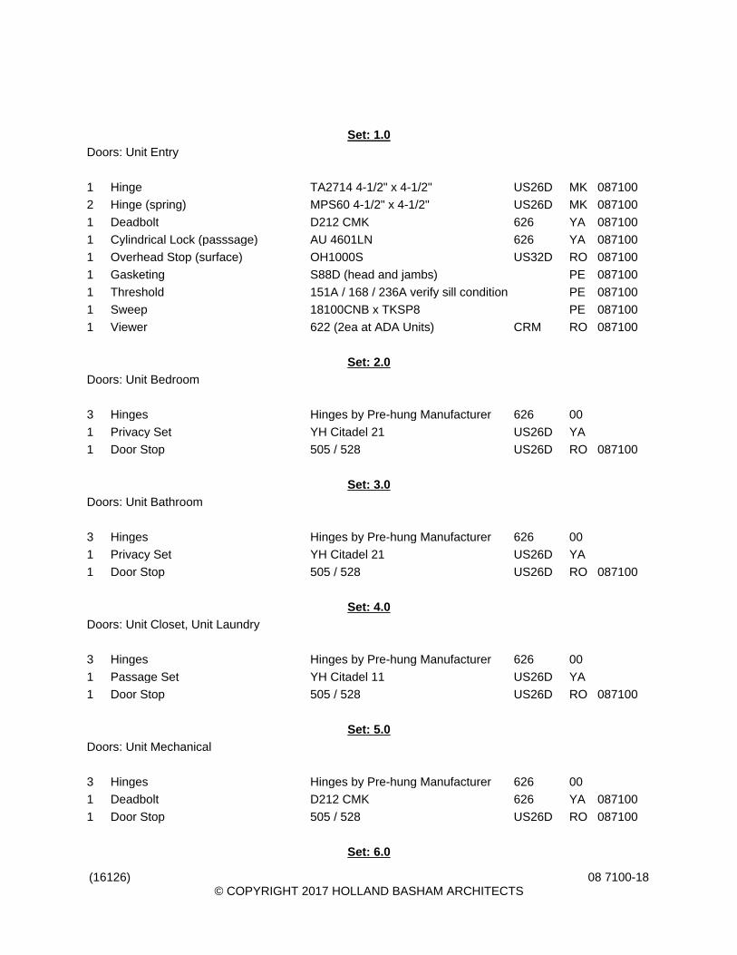
(16126) © COPYRIGHT 2017 HOLLAND BASHAM ARCHITECTS
08 7100-18
Set: 1.0
Doors: Unit Entry
1 Hinge TA2714 4-1/2" x 4-1/2" US26D MK 087100
2 Hinge (spring) MPS60 4-1/2" x 4-1/2" US26D MK 087100
1 Deadbolt D212 CMK 626 YA 087100
1 Cylindrical Lock (passsage) AU 4601LN 626 YA 087100
1 Overhead Stop (surface) OH1000S US32D RO 087100
1 Gasketing S88D (head and jambs) PE 087100
1 Threshold 151A / 168 / 236A verify sill condition PE 087100
1 Sweep 18100CNB x TKSP8 PE 087100
1 Viewer 622 (2ea at ADA Units) CRM RO 087100
Set: 2.0
Doors: Unit Bedroom
3 Hinges Hinges by Pre-hung Manufacturer 626 00
1 Privacy Set YH Citadel 21 US26D YA
1 Door Stop 505 / 528 US26D RO 087100
Set: 3.0
Doors: Unit Bathroom
3 Hinges Hinges by Pre-hung Manufacturer 626 00
1 Privacy Set YH Citadel 21 US26D YA
1 Door Stop 505 / 528 US26D RO 087100
Set: 4.0
Doors: Unit Closet, Unit Laundry
3 Hinges Hinges by Pre-hung Manufacturer 626 00
1 Passage Set YH Citadel 11 US26D YA
1 Door Stop 505 / 528 US26D RO 087100
Set: 5.0
Doors: Unit Mechanical
3 Hinges Hinges by Pre-hung Manufacturer 626 00
1 Deadbolt D212 CMK 626 YA 087100
1 Door Stop 505 / 528 US26D RO 087100
Set: 6.0

(16126) © COPYRIGHT 2017 HOLLAND BASHAM ARCHITECTS
08 7100-19
Doors: 671
3 Hinge (heavy weight) T4A3786 4-1/2" x 4-1/2" US26D MK 087100
1 Pull & Push Bar Set BF15747 x BTB x Decorative Ends US32D RO 087100
1 Overhead Stop (surface) OH1000S US32D RO 087100
1 Door Closer (reg arm, pull side) 3301 689 YA 087100
Set: 7.0
Doors: 201
3 Hinge (heavy weight) T4A3386 NRP 4-1/2" x 4-1/2" US32D MK 087100
1 Pull & Push Bar Set BF15747 x BTB x Decorative Ends US32D RO 087100
1 Door Closer (hd arm w/ stop, push side)
4430 689 YA 087100
1 Drop Plate 488 689 YA 087100
1 Blade Stop Spacer 891 689 YA 087100
1 Threshold 171A PE 087100
1 Sweep w/ drip 345ANB x TKSP8 PE 087100
1 Weatherstripping Weatherstripping by Door and Frame Supplier
00
Set: 8.0
Doors: 662.2
3 Hinge (heavy weight) T4A3386 NRP 4-1/2" x 4-1/2" US32D MK 087100
1 Cylindrical Lock (classroom) AU 4608LN CMK 626 YA 087100
1 Door Closer (hd arm w/ stop, push side)
4430 689 YA 087100
1 Drop Plate 488 689 YA 087100
1 Blade Stop Spacer 891 689 YA 087100
1 Threshold 171A PE 087100
1 Sweep w/ drip 345ANB x TKSP8 PE 087100
1 Weatherstripping Weatherstripping by Door and Frame Supplier
00
1 Rain Guard 346A (door width + 4") PE 087100
Set: 9.0
Doors: 263, 357, 363, 457, 463, 557, 563, 657
3 Hinge TA2714 4-1/2" x 4-1/2" US26D MK 087100
1 Cylindrical Lock (passsage) AU 4601LN 626 YA 087100
1 Door Closer (reg arm, pull side) 3301 689 YA 087100
1 Kick Plate K1050 8" x 2" LDW 4BE CSK US32D RO 087100
1 Wall Stop 406 US32D RO 087100

(16126) © COPYRIGHT 2017 HOLLAND BASHAM ARCHITECTS
08 7100-20
1 Gasketing S88D (head and jambs) PE 087100
Set: 10.0
Doors: 204
3 Hinge (heavy weight) T4A3786 NRP 5" x 4-1/2" US26D MK 087100
1 Cylindrical Lock (passsage) AU 4601LN 626 YA 087100
1 Door Closer (reg arm, pull side) 3301 689 YA 087100
1 Kick Plate K1050 8" x 2" LDW 4BE CSK US32D RO 087100
1 Wall Stop 406 US32D RO 087100
1 Threshold 171A PE 087100
1 Sweep 18100CNB x TKSP8 PE 087100
1 Weatherstripping 303AS x TKSP8 (head and jambs) PE 087100
Set: 11.0
Doors: S201
3 Hinge TA2714 NRP 4-1/2" x 4-1/2" US26D MK 087100
1 Exit Devcie (fire, rim, passage) 1800F x AU448F lever 689 YA 087100
1 Door Closer (reg arm, pull side) 3301 689 YA 087100
1 Kick Plate K1050 8" x 2" LDW 4BE CSK US32D RO 087100
1 Wall Stop 406 US32D RO 087100
1 Gasketing S88D (head and jambs) PE 087100
Set: 12.0
Doors: S103, S104, S105, S106, S203, S204, S205, S206, S302.2, S303, S304, S305
3 Hinge TA2714 NRP 4-1/2" x 4-1/2" US26D MK 087100
1 Exit Devcie (fire, rim, passage) 1800F x AU448F lever 689 YA 087100
1 Door Closer (reg arm, pull side) 3301 689 YA 087100
1 Kick Plate K1050 8" x 2" LDW 4BE CSK US32D RO 087100
1 Electromagnetic Holder 998 (verify voltage) 689 RF 087100
1 Gasketing S88D (head and jambs) PE 087100
Set: 13.0
Doors: S202
3 Hinge TA2714 NRP 4-1/2" x 4-1/2" US26D MK 087100
1 Exit Devcie (fire, rim, passage) 1800F x AU448F lever 689 YA 087100
1 Door Closer (hd arm w/ stop, push side)
3331 689 YA 087100
1 Kick Plate K1050 8" x 2" LDW 4BE CSK US32D RO 087100
1 Wall Stop 406 US32D RO 087100

(16126) © COPYRIGHT 2017 HOLLAND BASHAM ARCHITECTS
08 7100-21
1 Gasketing S88D (head and jambs) PE 087100
Set: 14.0
Doors: 101, S102.2, S301
3 Hinge TA2714 NRP 4-1/2" x 4-1/2" US26D MK 087100
1 Exit Devcie (fire, rim, passage) 1800F x AU448F lever 689 YA 087100
1 Door Closer (reg arm, pull side) 3301 689 YA 087100
1 Wall Stop 406 US32D RO 087100
1 Threshold 171A PE 087100
1 Sweep 18100CNB x TKSP8 PE 087100
1 Weatherstripping 303AS x TKSP8 (head and jambs) PE 087100
Set: 15.0
Doors: 110.2, 210.2
1 Hardware All Hardware by Door Supplier 00
Set: 16.0
Doors: 662.3
1 Cylinder Verify Type Needed CMK 626 YA 087100
1 Hardware Balance of Hardware by Door Supplier
00
Set: 17.0
Doors: 205, 207
1 Cylinder (mortise) 2153 CMK 626 YA 087100
1 Thumbturn Cylinder (mortise) S2053 626 YA 087100
1 Hardware Balance of Hardware by Door Supplier
00
Set: 18.0
Doors: 260, 360, 460, 560
6 Hinge TA2714 4-1/2" x 4-1/2" US26D MK 087100
1 Exit Device (fire, svr, exit only) 2170F LBR 630 YA 087100
1 Exit Device (fire, svr, class) 2170F x AU446F CMK 630 YA 087100
2 Door Closer (hd arm, push side) PR3301 689 YA 087100
2 Electromagnetic Holder 998 (verify voltage) 689 RF 087100
Set: 19.0
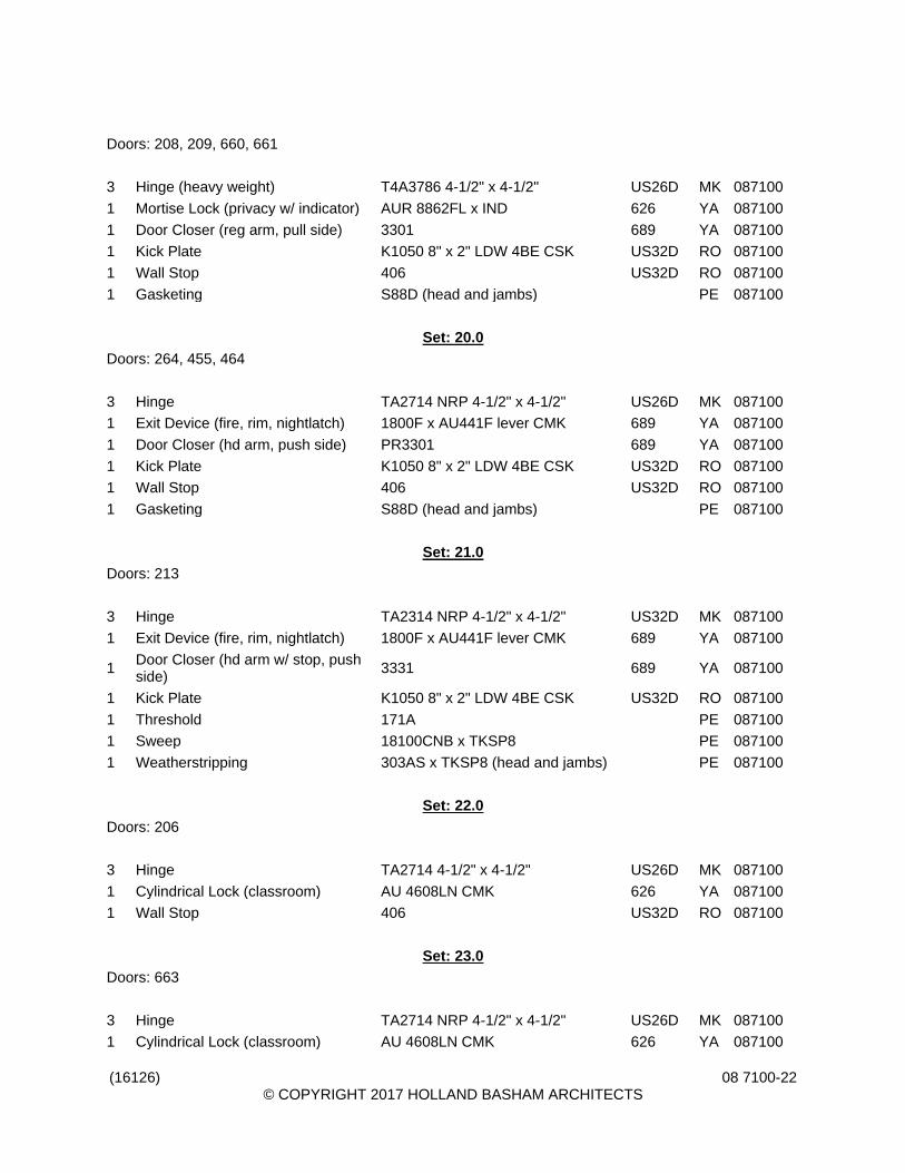
(16126) © COPYRIGHT 2017 HOLLAND BASHAM ARCHITECTS
08 7100-22
Doors: 208, 209, 660, 661
3 Hinge (heavy weight) T4A3786 4-1/2" x 4-1/2" US26D MK 087100
1 Mortise Lock (privacy w/ indicator) AUR 8862FL x IND 626 YA 087100
1 Door Closer (reg arm, pull side) 3301 689 YA 087100
1 Kick Plate K1050 8" x 2" LDW 4BE CSK US32D RO 087100
1 Wall Stop 406 US32D RO 087100
1 Gasketing S88D (head and jambs) PE 087100
Set: 20.0
Doors: 264, 455, 464
3 Hinge TA2714 NRP 4-1/2" x 4-1/2" US26D MK 087100
1 Exit Device (fire, rim, nightlatch) 1800F x AU441F lever CMK 689 YA 087100
1 Door Closer (hd arm, push side) PR3301 689 YA 087100
1 Kick Plate K1050 8" x 2" LDW 4BE CSK US32D RO 087100
1 Wall Stop 406 US32D RO 087100
1 Gasketing S88D (head and jambs) PE 087100
Set: 21.0
Doors: 213
3 Hinge TA2314 NRP 4-1/2" x 4-1/2" US32D MK 087100
1 Exit Device (fire, rim, nightlatch) 1800F x AU441F lever CMK 689 YA 087100
1 Door Closer (hd arm w/ stop, push side)
3331 689 YA 087100
1 Kick Plate K1050 8" x 2" LDW 4BE CSK US32D RO 087100
1 Threshold 171A PE 087100
1 Sweep 18100CNB x TKSP8 PE 087100
1 Weatherstripping 303AS x TKSP8 (head and jambs) PE 087100
Set: 22.0
Doors: 206
3 Hinge TA2714 4-1/2" x 4-1/2" US26D MK 087100
1 Cylindrical Lock (classroom) AU 4608LN CMK 626 YA 087100
1 Wall Stop 406 US32D RO 087100
Set: 23.0
Doors: 663
3 Hinge TA2714 NRP 4-1/2" x 4-1/2" US26D MK 087100
1 Cylindrical Lock (classroom) AU 4608LN CMK 626 YA 087100

(16126) © COPYRIGHT 2017 HOLLAND BASHAM ARCHITECTS
08 7100-23
1 Wall Stop 406 US32D RO 087100
Set: 24.0
Doors: 664
3 Hinge TA2314 NRP 4-1/2" x 4-1/2" US32D MK 087100
1 Cylindrical Lock (storeroom) AU 4605LN CMK 626 YA 087100
1 Overhead Stop (surface) OH1000S US32D RO 087100
1 Threshold 171A PE 087100
1 Sweep w/ drip 345ANB x TKSP8 PE 087100
1 Weatherstripping 303AS x TKSP8 (head and jambs) PE 087100
Set: 25.0
Doors: 352, 353, 355, 452, 453, 552, 553, 555, 652, 653, 655
3 Hinge TA2714 4-1/2" x 4-1/2" US26D MK 087100
1 Cylindrical Lock (storeroom) AU 4605LN CMK 626 YA 087100
1 Door Closer (reg arm, pull side) 3301 689 YA 087100
1 Wall Stop 406 US32D RO 087100
1 Gasketing S88D (head and jambs) PE 087100
Set: 26.0
Doors: 564, 658
3 Hinge TA2714 NRP 4-1/2" x 4-1/2" US26D MK 087100
1 Cylindrical Lock (storeroom) AU 4605LN CMK 626 YA 087100
1 Door Closer (hd arm w/ stop, push side)
3331 689 YA 087100
1 Gasketing S88D (head and jambs) PE 087100
Set: 27.0
Doors: 102
3 Hinge TA2714 4-1/2" x 4-1/2" US26D MK 087100
1 Cylindrical Lock (storeroom) AU 4605LN CMK 626 YA 087100
1 Door Closer (reg arm, pull side) 3301 689 YA 087100
1 Wall Stop 406 US32D RO 087100
1 Threshold 171A PE 087100
1 Sweep 18100CNB x TKSP8 PE 087100
1 Weatherstripping 303AS x TKSP8 (head and jambs) PE 087100
Set: 28.0
Doors: 111, 211

(16126) © COPYRIGHT 2017 HOLLAND BASHAM ARCHITECTS
08 7100-24
3 Hinge TA2314 NRP 4-1/2" x 4-1/2" US32D MK 087100
1 Cylindrical Lock (storeroom) AU 4605LN CMK 626 YA 087100
1 Door Closer (hd arm w/ stop, push side)
3331 689 YA 087100
1 Threshold 171A PE 087100
1 Sweep 18100CNB x TKSP8 PE 087100
1 Weatherstripping 303AS x TKSP8 (head and jambs) PE 087100
1 Latch Protector 321 US32D RO 087100
Set: 29.0
Doors: 112, 212
6 Hinge TA2314 NRP 4-1/2" x 4-1/2" US32D MK 087100
2 Manual Flush Bolt 555 US26D RO 087100
1 Dust Proof Strike 570 US26D RO 087100
1 Cylindrical Lock (storeroom) AU 4605LN CMK 626 YA 087100
1 Overhead Stop (surface) OH1000S US32D RO 087100
1 Door Closer (hd arm w/ stop, push side)
3331 689 YA 087100
2 Kick Plate K1050 8" x 1" LDW 4BE CSK US32D RO 087100
1 Threshold 171A PE 087100
2 Sweep 18100CNB x TKSP8 PE 087100
1 Weatherstripping 303AS x TKSP8 (head and jambs) PE 087100
1 Astragal Strip S772D PE 087100
1 Astragal Astragal by Door Supplier OT
1 Latch Protector 321 US32D RO 087100
Set: 30.0
Doors: 110.1, 210.1, S102.1, S302.1
3 Hinge (heavy weight) T4A3386 NRP 4-1/2" x 4-1/2" US32D MK 087100
1 Exit Device (rim, nightlatch) 2100 x 632F pull 630 YA 087100
1 Cylinder (rim) 1109 CMK 626 YA 087100
1 Electric Strike (rim, fail secure) 9600 630 HS 087100
1 Door Closer (hd arm w/ stop, push side)
4430 689 YA 087100
1 Kick Plate K1050 8" x 2" LDW 4BE CSK US32D RO 087100
1 Threshold 171A PE 087100
1 Sweep w/ drip 345ANB x TKSP8 PE 087100
1 Weatherstripping 303AS x TKSP8 (head and jambs) PE 087100
1 Rain Guard 346A (door width + 4") PE 087100
1 Card Reader Card Reader by Security Contractor OT
1 Door Position Switch DPS-x-BK SU 087100

(16126) © COPYRIGHT 2017 HOLLAND BASHAM ARCHITECTS
08 7100-25
1 Motion Sensor XMS SU 087100
1 Power Supply Power Supply (part of centralized location)
OT
Set: 31.0
Doors: 210.3
3 Hinge (heavy weight) T4A3386 NRP 5" x 4-1/2" US32D MK 087100
1 Exit Device (rim, nightlatch) 2100 x 632F pull 630 YA 087100
1 Cylinder (rim) 1109 CMK 626 YA 087100
1 Electric Strike (rim, fail secure) 9600 630 HS 087100
1 Door Closer (hd arm w/ stop, push side)
4430 689 YA 087100
1 Kick Plate K1050 8" x 2" LDW 4BE CSK US32D RO 087100
1 Threshold 171A PE 087100
1 Sweep w/ drip 345ANB x TKSP8 PE 087100
1 Weatherstripping 303AS x TKSP8 (head and jambs) PE 087100
1 Rain Guard 346A (door width + 4") PE 087100
1 Card Reader Card Reader by Security Contractor OT
1 Door Position Switch DPS-x-BK SU 087100
1 Motion Sensor XMS SU 087100
1 Power Supply Power Supply (part of centralized location)
OT
Set: 32.0
Doors: 203.1
3 Hinge (heavy weight) T4A3786 NRP 4-1/2" x 4-1/2" US26D MK 087100
1 Exit Device (rim, nightlatch) 2100 x 632F pull 630 YA 087100
1 Cylinder (rim) 1109 CMK 626 YA 087100
1 Electric Strike (rim, fail secure) 9600 630 HS 087100
1 Door Closer (hd arm w/ stop, push side)
4430 689 YA 087100
1 Drop Plate 488 689 YA 087100
1 Blade Stop Spacer 891 689 YA 087100
1 Card Reader Card Reader by Security Contractor OT
1 Door Position Switch DPS-x-BK SU 087100
1 Motion Sensor XMS SU 087100
1 Power Supply Power Supply (part of centralized location)
OT
Set: 33.0
Doors: 203.2

(16126) © COPYRIGHT 2017 HOLLAND BASHAM ARCHITECTS
08 7100-26
3 Hinge (heavy weight) T4A3386 NRP 4-1/2" x 4-1/2" US32D MK 087100
1 Exit Device (rim, nightlatch) 2100 x 632F pull 630 YA 087100
1 Cylinder (rim) 1109 CMK 626 YA 087100
1 Electric Strike (rim, fail secure) 9600 630 HS 087100
1 Door Closer (hd arm w/ stop, push side)
4430 689 YA 087100
1 Drop Plate 488 689 YA 087100
1 Blade Stop Spacer 891 689 YA 087100
1 Threshold 171A PE 087100
1 Sweep w/ drip 345ANB x TKSP8 PE 087100
1 Weatherstripping Weatherstripping by Door and Frame Supplier
00
1 Rain Guard 346A (door width + 4") PE 087100
1 Card Reader Card Reader by Security Contractor OT
1 Door Position Switch DPS-x-BK SU 087100
1 Motion Sensor XMS SU 087100
1 Power Supply Power Supply (part of centralized location)
OT
Set: 34.0
Doors: 662.1, 670
3 Hinge (heavy weight) T4A3786 NRP 4-1/2" x 4-1/2" US26D MK 087100
1 Cylindrical Lock (storeroom) AU 4605LN CMK 626 YA 087100
1 Electric Strike (fire, mortise, fail secure)
4500C 630 HS 087100
1 Door Closer (hd arm w/ stop, push side)
3331 689 YA 087100
1 Card Reader Card Reader by Security Contractor OT
1 Door Position Switch DPS-x-BK SU 087100
1 Motion Sensor XMS SU 087100
Set: 35.0
Doors: Access Controls
1 Access Control Software Access Control Hardware as Descripted Below by RS2
00
1 Card Reader Card Reader I Class SE R40 (verify quanity per plans)
HG
1 Software SLI-SOFT by RS2 00
1 Software S-WEB by RS2 00
1 Software S-TERM by RS2 00
1 Software S-NOTIFY by RS2 00
1 Hardware PC- CLIENT - EXISTING 00

(16126) © COPYRIGHT 2017 HOLLAND BASHAM ARCHITECTS
08 7100-27
1 Controller EP-1502 by RS2 00
1 Reader Interface MR-51 by RS2 00
1 Reader Interface MR-52 by RS2 00
1 Input Module MR-16IN by RS2 00
1 Output Module MR-16OUT by RS2 00
1 Enclosure NCL-12-CAB by RS2 00
1 Back-up Battery BAT-70 by RS2 00
1 Power Supply AL400ULX by Altronic 00
1 Power Supply AL600ULX by Altronic 00
1 Distribution PD8CD by Altronic 00
1 Composite Cable AC251822B by West Penn 00
1 Access Control DEVICE INSTALLATION by Contractor
00
1 Access Control WIRE INSTALLATION by Contractor 00
1 Access Control SOFTWARE INTERGRATION by Contractor
00
1 Access Control 4- HOUR TRAINING SESSION by Contractor
00
500 Cards 3050ICLASS SE CARDS HG
1 Misc Hardware
Misc Items for Garage Door - Door Loop Sensor (saw cut into floor) and / or Pedestal ( w/ Long Read) by Securtiy Contractor
OT
END OF SECTION

(16126)© COPYRIGHT 2017 HOLLAND BASHAM ARCHITECTS
08 8000-1
SECTION 08 8000GLAZING
PART 1 GENERAL1.01 SECTION INCLUDES
A. Glazing units.B. Mirrors.C. Glazing compounds and accessories.
1.02 RELATED REQUIREMENTSA. Section 08 1113 - Hollow Metal Doors and Frames: Glazed lites in doors and borrowed lites.B. Section 08 3613 - Sectional Doors: Glazed lites in doors.C. Section 08 4126 - All-Glass Entrances and Storefronts: Glazing furnished as part of entrance
assembly.D. Section 08 5313 - Vinyl Windows: Glazing furnished by window manufacturer.
1.03 REFERENCE STANDARDSA. ASTM C864 - Standard Specification for Dense Elastomeric Compression Seal Gaskets,
Setting Blocks, and Spacers; 2005 (Reapproved 2011).B. ASTM C920 - Standard Specification for Elastomeric Joint Sealants; 2014.C. ASTM C1036 - Standard Specification for Flat Glass; 2011.D. ASTM C1048 - Standard Specification for Heat-Strengthened and Fully Tempered Flat Glass;
2012.E. ASTM C1193 - Standard Guide for Use of Joint Sealants; 2013.F. ASTM C1376 - Standard Specification for Pyrolytic and Vacuum Deposition Coatings on Flat
Glass; 2015.G. ASTM E1300 - Standard Practice for Determining Load Resistance of Glass in Buildings;
2012a.H. ASTM E2190 - Standard Specification for Insulating Glass Unit Performance and Evaluation;
2010.I. GANA (GM) - GANA Glazing Manual; 2009.J. GANA (SM) - GANA Sealant Manual; 2008.K. GANA (TIPS) - Mirrors: Handle with Extreme Care (Tips for the Professional on the Care and
Handling of Mirrors); 2011.L. IGMA TM-3000 - North American Glazing Guidelines for Sealed Insulating Glass Units for
Commercial & Residential Use; 1990 (2004).M. ITS (DIR) - Directory of Listed Products; current edition.N. NFRC 100 - Procedure for Determining Fenestration Product U-factors; 2014.O. NFRC 200 - Procedure for Determining Fenestration Product Solar Heat Gain Coefficient and
Visible Transmittance at Normal Incidence; 2014.P. NFRC 300 - Test Method for Determining the Solar Optical Properties of Glazing Materials and
Systems; 2014.Q. UL (DIR) - Online Certifications Directory; current listings at database.ul.com.
1.04 DEFINITIONSA. Sealed Insulating Glass Unit Surfaces:
1. Surface 1 - Exterior surface of outer pane.2. Surface 2 - Interior surface of outer pane.3. Surface 3 - Interior surface of inner pane.

(16126)© COPYRIGHT 2017 HOLLAND BASHAM ARCHITECTS
08 8000-2
4. Surface 4 - Exterior surface of inner pane.1.05 SUBMITTALS
A. See Section 01 3000 - Administrative Requirements, for submittal procedures.B. Product Data on Glazing Unit Types: Provide structural, physical and environmental
characteristics, size limitations, special handling and installation requirements.C. Product Data on Glazing Compounds and Accessories: Provide chemical, functional, and
environmental characteristics, limitations, special application requirements. Identify availablecolors.
D. Samples: Submit two samples 12 by 12 inch in size of glass units, showing coloration.E. Certificates: Certify that products meet or exceed specified requirements.
1.06 QUALITY ASSURANCEA. Perform Work in accordance with GANA (GM) and IGMA TM-3000 for glazing installation
methods. B. Installer Qualifications: Company specializing in performing work of the type specified and with
at least three years documented experience.C. Fabricate, store, transport, receive, install, and clean mirrors in accordance with
recommendations of GANA (TIPS).1.07 FIELD CONDITIONS
A. Do not install glazing when ambient temperature is less than 40 degrees F.B. Maintain minimum ambient temperature before, during and 24 hours after installation of glazing
compounds.1.08 WARRANTY
A. See Section 01 7800 - Closeout Submittals, for additional warranty requirements.B. Warranty covers specific items identified below due to normal conditions of use and not to
handling, installing, and cleaning practices contrary to the glass manufacturer’s publishedinstructions.
C. Provide five year manufacturer warranty for reflective coating on mirrors and replacement ofsame.
PART 2 PRODUCTS2.01 MANUFACTURERS
A. Glass Fabricators:1. Insulite Glass Company, Inc.: www.insuliteglass.com.2. Viracon, Inc; _____: www.viracon.com.3. Substitutions: Refer to Section 01 6000 - Product Requirements.
B. Float Glass Manufacturers:1. AGC Glass Company North America, Inc; _____: www.us.agc.com.2. Cardinal Glass Industries; _____: www.cardinalcorp.com.3. Guardian Industries Corp; _____: www.sunguardglass.com.4. Pilkington North America Inc; _____: www.pilkington.com/na.5. PPG Industries, Inc; _____: www.ppgideascapes.com.6. Substitutions: Refer to Section 01 6000 - Product Requirements.
C. Laminated Glass Manufacturers:1. Cardinal Glass Industries; _____: www.cardinalcorp.com.2. Viracon, Architectural Glass segment of Apogee Enterprises, Inc; _____:
www.viracon.com.3. Substitutions: Refer to Section 01 6000 - Product Requirements.
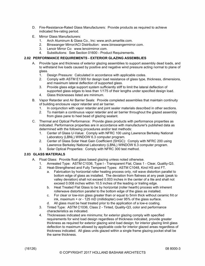
(16126)© COPYRIGHT 2017 HOLLAND BASHAM ARCHITECTS
08 8000-3
D. Fire-Resistance-Rated Glass Manufacturers: Provide products as required to achieveindicated fire-rating period.
E. Mirror Glass Manufacturers:1. Arch Aluminum & Glass Co., Inc: www.arch.amarlite.com.2. Binswanger Mirror/ACI Distribution: www.binswangermirror.com.3. Lenoir Mirror Co: www.lenoirmirror.com.4. Substitutions: See Section 01600 - Product Requirements.
2.02 PERFORMANCE REQUIREMENTS - EXTERIOR GLAZING ASSEMBLIESA. Provide type and thickness of exterior glazing assemblies to support assembly dead loads, and
to withstand live loads caused by positive and negative wind pressure acting normal to plane ofglass.1. Design Pressure: Calculated in accordance with applicable codes.2. Comply with ASTM E1300 for design load resistance of glass type, thickness, dimensions,
and maximum lateral deflection of supported glass.3. Provide glass edge support system sufficiently stiff to limit the lateral deflection of
supported glass edges to less than 1/175 of their lengths under specified design load.4. Glass thicknesses listed are minimum.
B. Vapor Retarder and Air Barrier Seals: Provide completed assemblies that maintain continuityof building enclosure vapor retarder and air barrier.1. In conjunction with vapor retarder and joint sealer materials described in other sections.2. To maintain a continuous vapor retarder and air barrier throughout the glazed assembly
from glass pane to heel bead of glazing sealant.C. Thermal and Optical Performance: Provide glass products with performance properties as
indicated. Performance properties are in accordance with manufacturer's published data asdetermined with the following procedures and/or test methods:1. Center of Glass U-Value: Comply with NFRC 100 using Lawrence Berkeley National
Laboratory (LBNL) WINDOW 6.3 computer program.2. Center of Glass Solar Heat Gain Coefficient (SHGC): Comply with NFRC 200 using
Lawrence Berkeley National Laboratory (LBNL) WINDOW 6.3 computer program.3. Solar Optical Properties: Comply with NFRC 300 test method.
2.03 GLASS MATERIALSA. Float Glass: Provide float glass based glazing unless noted otherwise.
1. Annealed Type: ASTM C1036, Type I - Transparent Flat, Class 1 - Clear, Quality-Q3.2. Heat-Strengthened and Fully Tempered Types: ASTM C1048, Kind HS and FT.
a. Fabrication by horizontal roller heating process only, roll wave distortion parallel tobottom edge of glass as installed. The deviation from flatness at any peak (peak tovalley deviation) shall not exceed 0.003 inches in the center of a lite and shall notexceed 0.008 inches within 10.5 inches of the leading or trailing edge.
b. Heat Treated Flat Glass to be by horizontal (roller hearth) process with inherentrollerwave distortion parallel to the bottom edge of the glass as installed.
c. For clear or low-iron glass greater than or equal to 5mm thick without ceramic frit orink, maximum + or - 125 mD (millidiopter) over 95% of the glass surface.
d. All glass must be heat treated prior to the application of a low-e coating.3. Tinted Type: ASTM C1036, Class 2 - Tinted, Quality-Q3, color and performance
characteristics as indicated.4. Thicknesses indicated are minimums; for exterior glazing comply with specified
requirements for wind load design regardless of thickness indicated, provide greaterthickness as required for exterior glazing wind load design; for interior glazing limit glassdeflection to maximum allowed by applicable code for interior glazed areas regardless ofthickness indicated. All glass units glazed within a single frame glazing pocket shall bethe same thickness.
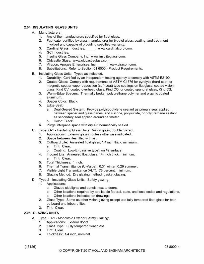
(16126)© COPYRIGHT 2017 HOLLAND BASHAM ARCHITECTS
08 8000-4
2.04 INSULATING GLASS UNITSA. Manufacturers:
1. Any of the manufacturers specified for float glass.2. Fabricator certified by glass manufacturer for type of glass, coating, and treatment
involved and capable of providing specified warranty.3. Cardinal Glass Industries; _____: www.cardinalcorp.com.4. GCI Industries.5. Insulite Glass Company, Inc: www.insuliteglass.com.6. Oldcastle Glass: www.oldcastleglass.com.7. Viracon, Apogee Enterprises, Inc; _____: www.viracon.com.8. Substitutions: Refer to Section 01 6000 - Product Requirements.
B. Insulating Glass Units: Types as indicated.1. Durability: Certified by an independent testing agency to comply with ASTM E2190.2. Coated Glass: Comply with requirements of ASTM C1376 for pyrolytic (hard-coat) or
magnetic sputter vapor deposition (soft-coat) type coatings on flat glass; coated visionglass, Kind CV; coated overhead glass, Kind CO; or coated spandrel glass, Kind CS.
3. Warm-Edge Spacers: Thermally broken polyurethane polymer and organic coatedaluminum.
4. Spacer Color: Black.5. Edge Seal:
a. Dual-Sealed System: Provide polyisobutylene sealant as primary seal appliedbetween spacer and glass panes, and silicone, polysulfide, or polyurethane sealantas secondary seal applied around perimeter.
b. Color: Black.6. Purge interpane space with dry air, hermetically sealed.
C. Type IG-1 - Insulating Glass Units: Vision glass, double glazed.1. Applications: Exterior glazing unless otherwise indicated.2. Space between lites filled with air.3. Outboard Lite: Annealed float glass, 1/4 inch thick, minimum.
a. Tint: Clear.b. Coating: Low-E (passive type), on #2 surface.
4. Inboard Lite: Annealed float glass, 1/4 inch thick, minimum.a. Tint: Clear.
5. Total Thickness: 1 inch.6. Thermal Transmittance (U-Value): 0.31 winter, 0.29 summer.7. Visible Light Transmittance (VLT): 76 percent, minimum.8. Glazing Method: Dry glazing method, gasket glazing.
D. Type 2 - Insulating Glass Units: Safety glazing.1. Applications:
a. Glazed sidelights and panels next to doors.b. Other locations required by applicable federal, state, and local codes and regulations.c. Other locations indicated on drawings.
2. Glass Type: Same as other vision glazing except use fully tempered float glass for bothoutboard and inboard lites.
3. Tint: Clear.2.05 GLAZING UNITS
A. Type FG-1 - Monolithic Exterior Safety Glazing:1. Applications: Exterior doors.2. Glass Type: Fully tempered float glass.3. Tint: Clear.4. Thickness: 1/4 inch, nominal.
(16126)© COPYRIGHT 2017 HOLLAND BASHAM ARCHITECTS
08 8000-5
5. Visible Light Transmittance (VLT): 76 percent, minimum.6. Glazing Method: Dry glazing method, gasket glazing.
B. Type FG-2 - Monolithic Interior Vision Glazing:1. Applications: Interior glazing unless otherwise indicated.2. Glass Type: Annealed float glass.3. Tint: Clear.4. Thickness: 1/4 inch, nominal.5. Glazing Method: Gasket glazing or any interior method specified.
C. Type FG-3 - Fire-Resistance-Rated Glazing: Type, thickness, and configuration as required toachieve indicated ratings.1. Applications:
a. Glazing in fire-rated door assembly.b. Glazing in sidelites, borrowed lites, and other glazed openings in fire-rated wall
assemblies.2. Provide products listed by ITS (DIR) or UL (DIR) and approved by authorities having
jurisdiction.3. Glazing Method: As required for fire rating.4. Fire-Resistance-Rating Period: As indicated on drawings.
D. Type FG-4 - Fire-Protection-Rated Glazing: Type, thickness, and configuration as required toachieve indicated ratings.1. Applications:
a. Glazing in fire-rated door assembly.b. Glazing in fire-rated window assembly.c. Other locations as indicated on drawings.
2. Glass Type: Specialty tempered float glass.3. Provide products listed by ITS (DIR) or UL (DIR) and approved by authorities having
jurisdiction.4. Glazing Method: As required for fire rating.
E. Type MR-1 - Mirror Glass:1. Application: Locations indicated on the drawings.2. Type: Fully tempered float glass as specified.3. Tint: Clear.4. Thickness: 1/4 inch.
2.06 GLAZING COMPOUNDSA. Glazing Putty: Polymer modified latex, knife grade consistency; grey color.B. Type 2 - Silicone Sealant: Single component; neutral curing; capable of water immersion
without loss of properties; non-bleeding, non-staining; ASTM C920, Type S, Grade NS, Class25, Uses M, A, and G; with cured Shore A hardness range of 15 to 25; _____ color.
C. Manufacturers:1. Bostik Inc: www.bostik-us.com.2. Dow Corning Corporation: www.dowcorning.com/construction.3. Momentive Performance Materials, Inc: www.momentive.com.4. Pecora Corporation: www.pecora.com.5. BASF Corporation: www.basf.com/us/en.html.6. Substitutions: Refer to Section 01 6000 - Product Requirements.
2.07 ACCESSORIESA. Setting Blocks: Neoprene, EPDM, TPE (Santoprene) or Silicone, 80 to 90 Shore A durometer
hardness; ASTM C864 Option I. Length of 0.1 inch for each square foot of glazing or minimum4 inch x width of glazing rabbet space minus 1/16 inch x height to suit glazing method and paneweight and area.
(16126)© COPYRIGHT 2017 HOLLAND BASHAM ARCHITECTS
08 8000-6
B. Spacer Shims: Neoprene or Silicone, 50 to 60 Shore A durometer hardness; ASTM C864Option I. Minimum 3 inch long x one half the height of the glazing stop x thickness to suitapplication, self adhesive on one face.
C. Glazing Tape: Provide preformed butyl compound or Closed cell polyvinyl chloride foam,coiled on release paper over adhesive on two sides, to effect an air barrier and vapor retarderseal.
D. Glazing Gaskets: Resilient silicone extruded shape to suit glazing channel retaining slot;ASTM C864 Option I; color black.
E. Glazing Clips: Manufacturer's standard type.PART 3 EXECUTION3.01 VERIFICATION OF CONDITIONS
A. Verify that openings for glazing are correctly sized and within tolerances, including those forsize, squareness, and offsets at corners.
B. Verify that surfaces of glazing channels or recesses are clean, free of obstructions that mayimpede moisture movement, weeps are clear, and support framing is ready to receive glazingsystem.
3.02 PREPARATIONA. Clean contact surfaces with appropriate solvent and wipe dry within maximum of 24 hours
before glazing. Remove coatings that are not tightly bonded to substrates.B. Seal porous glazing channels or recesses with substrate compatible primer or sealer.C. Prime surfaces scheduled to receive sealant where required for proper sealant adhesion.
3.03 INSTALLATION, GENERALA. Install glazing in compliance with written instructions of glass, gaskets, and other glazing
material manufacturers, unless more stringent requirements are indicated, including those inglazing referenced standards.
B. Install glazing sealants in accordance with ASTM C1193, GANA (SM), and manufacturer'sinstructions.
C. Do not exceed edge pressures around perimeter of glass lites as stipulated by glassmanufacturer.
D. Set glass lites of system with uniform pattern, draw, bow, and similar characteristics.E. Set glass lites in proper orientation so that coatings face exterior or interior as indicated.F. Prevent glass from contact with any contaminating substances that may be the result of
construction operations such as, and not limited to the following; weld splatter, fire-safing,plastering, mortar droppings, etc.
3.04 INSTALLATION - DRY GLAZING METHOD (GASKET GLAZING)A. Application - Exterior and/or Interior Glazed: Set glazing infills from either the exterior or the
interior of the building.B. Place setting blocks at 1/4 points with edge block no more than 6 inch from corners.C. Rest glazing on setting blocks and push against fixed stop with sufficient pressure on gasket to
attain full contact.D. Install removable stops without displacing glazing gasket; exert pressure for full continuous
contact.3.05 INSTALLATION - DRY GLAZING METHOD (TAPE AND TAPE)
A. Application - Interior Glazed: Set glazing infills from the interior of the building.B. Cut glazing tape to length and set against permanent stops, projecting 1/16 inch above sight
line.
(16126)© COPYRIGHT 2017 HOLLAND BASHAM ARCHITECTS
08 8000-7
C. Place setting blocks at 1/4 points with edge block no more than 6 inch from corners.D. Rest glazing on setting blocks and push against tape for full contact at perimeter of pane or
unit.E. Place glazing tape on free perimeter of glazing in same manner described above.F. Install removable stop without displacement of tape. Exert pressure on tape for full continuous
contact.G. Carefully trim protruding tape with knife.
3.06 INSTALLATION - WET/DRY GLAZING METHOD (TAPE AND SEALANT)A. Application - Interior Glazed: Set glazing infills from the interior of the building.B. Cut glazing tape to length and install against permanent stops, projecting 1/16 inch above sight
line.C. Place setting blocks at 1/4 points with edge block no more than 6 inch from corners.D. Rest glazing on setting blocks and push against tape to ensure full contact at perimeter of pane
or unit.E. Install removable stops, spacer shims inserted between glazing and applied stops at 24 inch
intervals, 1/4 inch below sight line.F. Fill gaps between pane and applied stop with ________ type sealant to depth equal to bite on
glazing, to uniform and level line.G. Carefully trim protruding tape with knife.
3.07 INSTALLATION - MIRRORSA. Install mirrors in accordance with GANA (TIPS) recommendations.B. Set mirrors plumb and level, free of optical distortion.C. Set mirrors with edge clearance free of surrounding construction including countertops or
backsplashes.D. Frameless Mirrors: Set mirrors with adhesive, applied in accordance with adhesive
manufacturer's instructions.3.08 FIELD QUALITY CONTROL
A. Glass and Glazing product manufacturers to provide field surveillance of the installation of theirproducts.
B. Monitor and report installation procedures and unacceptable conditions.3.09 CLEANING
A. Remove excess glazing materials from finish surfaces immediately after application usingsolvents or cleaners recommended by manufacturers.
B. Remove non-permanent labels immediately after glazing installation is complete.C. Clean glass and adjacent surfaces after sealants are fully cured.
3.10 PROTECTIONA. After installation, mark pane with an 'X' by using removable plastic tape or paste; do not mark
heat absorbing or reflective glass units.END OF SECTION

(16126)© COPYRIGHT 2017 HOLLAND BASHAM ARCHITECTS
08 8000-8
HOLLAND BASHAM ARCHITECTS 1 1 9 S O U T H 4 9 A V E N U E O M A H A , N E B R A S K A 6 8 1 3 2 4 0 2 - 5 5 1 - 0 8 0 0 F A X : 4 0 2 - 5 5 1 - 2 2 9 5 E M A I L : H B A @ H B A 1 . C O M
DIVISION 09
FINISHES
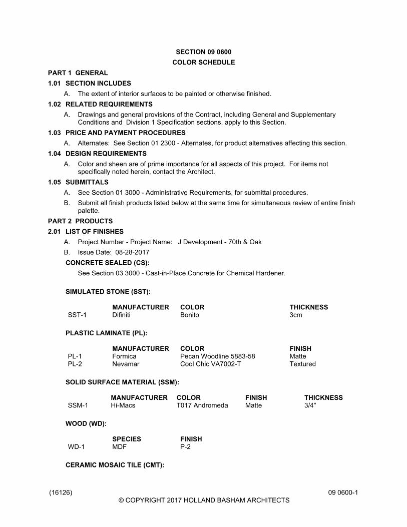
(16126)© COPYRIGHT 2017 HOLLAND BASHAM ARCHITECTS
09 0600-1
SECTION 09 0600COLOR SCHEDULE
PART 1 GENERAL1.01 SECTION INCLUDES
A. The extent of interior surfaces to be painted or otherwise finished.1.02 RELATED REQUIREMENTS
A. Drawings and general provisions of the Contract, including General and SupplementaryConditions and Division 1 Specification sections, apply to this Section.
1.03 PRICE AND PAYMENT PROCEDURESA. Alternates: See Section 01 2300 - Alternates, for product alternatives affecting this section.
1.04 DESIGN REQUIREMENTSA. Color and sheen are of prime importance for all aspects of this project. For items not
specifically noted herein, contact the Architect.1.05 SUBMITTALS
A. See Section 01 3000 - Administrative Requirements, for submittal procedures.B. Submit all finish products listed below at the same time for simultaneous review of entire finish
palette.PART 2 PRODUCTS2.01 LIST OF FINISHES
A. Project Number - Project Name: J Development - 70th & OakB. Issue Date: 08-28-2017CONCRETE SEALED (CS):
See Section 03 3000 - Cast-in-Place Concrete for Chemical Hardener.
SIMULATED STONE (SST):
MANUFACTURER COLOR THICKNESSSST-1 Difiniti Bonito 3cm
PLASTIC LAMINATE (PL):
MANUFACTURER COLOR FINISHPL-1 Formica Pecan Woodline 5883-58 MattePL-2 Nevamar Cool Chic VA7002-T Textured
SOLID SURFACE MATERIAL (SSM):
MANUFACTURER COLOR FINISH THICKNESSSSM-1 Hi-Macs T017 Andromeda Matte 3/4"
WOOD (WD):
SPECIES FINISHWD-1 MDF P-2
CERAMIC MOSAIC TILE (CMT):
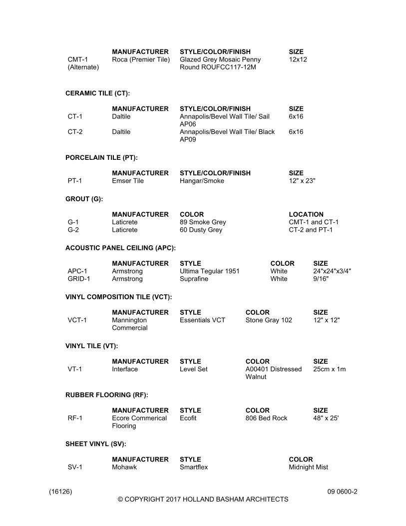
(16126)© COPYRIGHT 2017 HOLLAND BASHAM ARCHITECTS
09 0600-2
MANUFACTURER STYLE/COLOR/FINISH SIZECMT-1(Alternate)
Roca (Premier Tile) Glazed Grey Mosaic PennyRound ROUFCC117-12M
12x12
CERAMIC TILE (CT):
MANUFACTURER STYLE/COLOR/FINISH SIZECT-1 Daltile Annapolis/Bevel Wall Tile/ Sail
AP066x16
CT-2 Daltile Annapolis/Bevel Wall Tile/ BlackAP09
6x16
PORCELAIN TILE (PT):
MANUFACTURER STYLE/COLOR/FINISH SIZEPT-1 Emser Tile Hangar/Smoke 12" x 23"
GROUT (G):
MANUFACTURER COLOR LOCATIONG-1 Laticrete 89 Smoke Grey CMT-1 and CT-1G-2 Laticrete 60 Dusty Grey CT-2 and PT-1
ACOUSTIC PANEL CEILING (APC):
MANUFACTURER STYLE COLOR SIZEAPC-1 Armstrong Ultima Tegular 1951 White 24"x24"x3/4"GRID-1 Armstrong Suprafine White 9/16"
VINYL COMPOSITION TILE (VCT):
MANUFACTURER STYLE COLOR SIZEVCT-1 Mannington
CommercialEssentials VCT Stone Gray 102 12" x 12"
VINYL TILE (VT):
MANUFACTURER STYLE COLOR SIZEVT-1 Interface Level Set A00401 Distressed
Walnut25cm x 1m
RUBBER FLOORING (RF):
MANUFACTURER STYLE COLOR SIZERF-1 Ecore Commerical
FlooringEcofit 806 Bed Rock 48" x 25'
SHEET VINYL (SV):
MANUFACTURER STYLE COLORSV-1 Mohawk Smartflex Midnight Mist
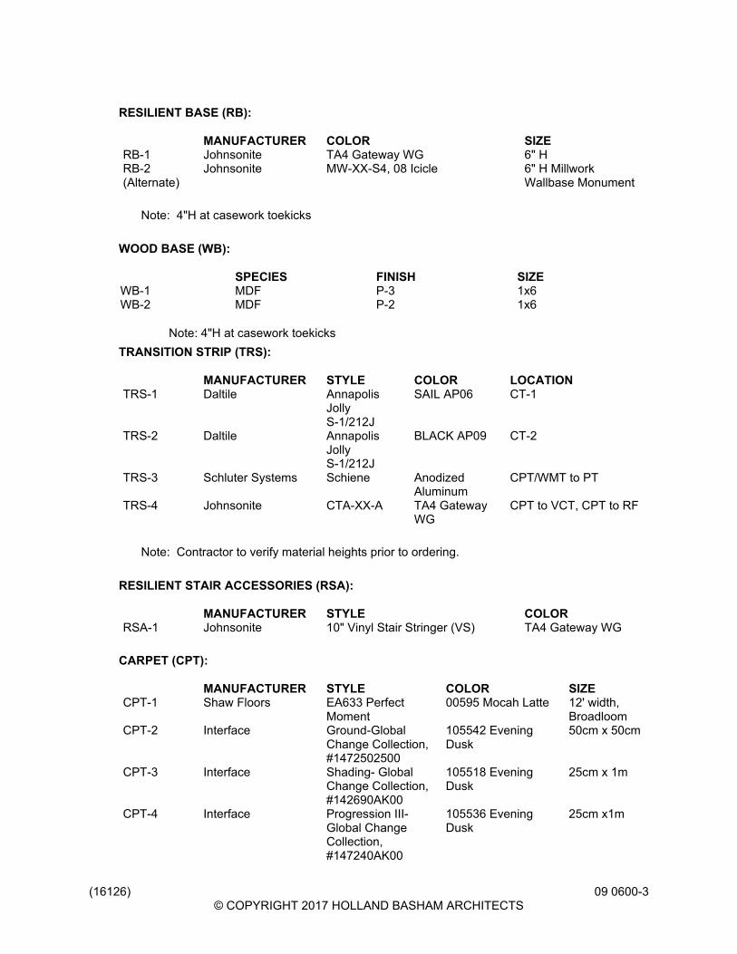
(16126)© COPYRIGHT 2017 HOLLAND BASHAM ARCHITECTS
09 0600-3
RESILIENT BASE (RB):
MANUFACTURER COLOR SIZERB-1 Johnsonite TA4 Gateway WG 6" H RB-2(Alternate)
Johnsonite MW-XX-S4, 08 Icicle 6" H MillworkWallbase Monument
Note: 4"H at casework toekicks
WOOD BASE (WB):
SPECIES FINISH SIZEWB-1 MDF P-3 1x6WB-2 MDF P-2 1x6
Note: 4"H at casework toekicksTRANSITION STRIP (TRS):
MANUFACTURER STYLE COLOR LOCATIONTRS-1 Daltile Annapolis
JollyS-1/212J
SAIL AP06 CT-1
TRS-2 Daltile AnnapolisJollyS-1/212J
BLACK AP09 CT-2
TRS-3 Schluter Systems Schiene AnodizedAluminum
CPT/WMT to PT
TRS-4 Johnsonite CTA-XX-A TA4 GatewayWG
CPT to VCT, CPT to RF
Note: Contractor to verify material heights prior to ordering.
RESILIENT STAIR ACCESSORIES (RSA):
MANUFACTURER STYLE COLORRSA-1 Johnsonite 10" Vinyl Stair Stringer (VS) TA4 Gateway WG
CARPET (CPT):
MANUFACTURER STYLE COLOR SIZECPT-1 Shaw Floors EA633 Perfect
Moment00595 Mocah Latte 12' width,
BroadloomCPT-2 Interface Ground-Global
Change Collection,#1472502500
105542 EveningDusk
50cm x 50cm
CPT-3 Interface Shading- GlobalChange Collection,#142690AK00
105518 EveningDusk
25cm x 1m
CPT-4 Interface Progression III-Global ChangeCollection,#147240AK00
105536 EveningDusk
25cm x1m

(16126)© COPYRIGHT 2017 HOLLAND BASHAM ARCHITECTS
09 0600-4
WALK-OFF MAT (WMT):
MANUFACTURER STYLE COLOR SIZEWMT-1 Shaw Contract
Group5T031 Welcome IITile
31500 Ebony 24x24
WMT-2 Shaw ContractGroup
60745 Welcome IIBroadloom
31500 Ebony 12' width,Broadloom
PAINT (P):
MANUFACTURER COLORP-1 Sherwin Williams SW 7672 Knitting NeedlesP-2 Sherwin Williams SW 7069 Iron OreP-3 Sherwin Williams SW 7005 Pure WhiteP-4 Sherwin Williams SW 7673 Pewter CastP-5 Sherwin Williams SW 6251 OuterspaceP-6 Sherwin Williams SW 6349 Pennywise
HIGH-PERFORMANCE COATINGS (HPC):
MANUFACTURER COLORHPC-1 Tenemec Sherwin Williams SW 7673
Pewter CastHPC-2 Tenemec Sherwin Williams SW 7069 Iron
Ore
CORNER GUARD (CG):
MANUFACTURER MODEL COLORCG-1 Inpro 150BN, .080", 4'H Castle 0256
FIBERGLASS REINFORCED PLASTIC (FRP):
MANUFACTURER COLORFRP-1 Crane Composites Sandstone Texture, Morning Mist
(636)
Note: Provide harmonizing trim pieces as required.
ROLLER SHADES (RS):
MANUFACTURER STYLE COLORRS-1 Mechoshade Soho Collection 1600 Series (3%
Open)1612Thompson(Charcoal)
HORIZONTAL LOUVER BLINDS (HLB):
MANUFACTURER STYLE COLORHLB-1 SWF Contract Graber Lake Forest 2" Faux
WoodMarshmallow 5742
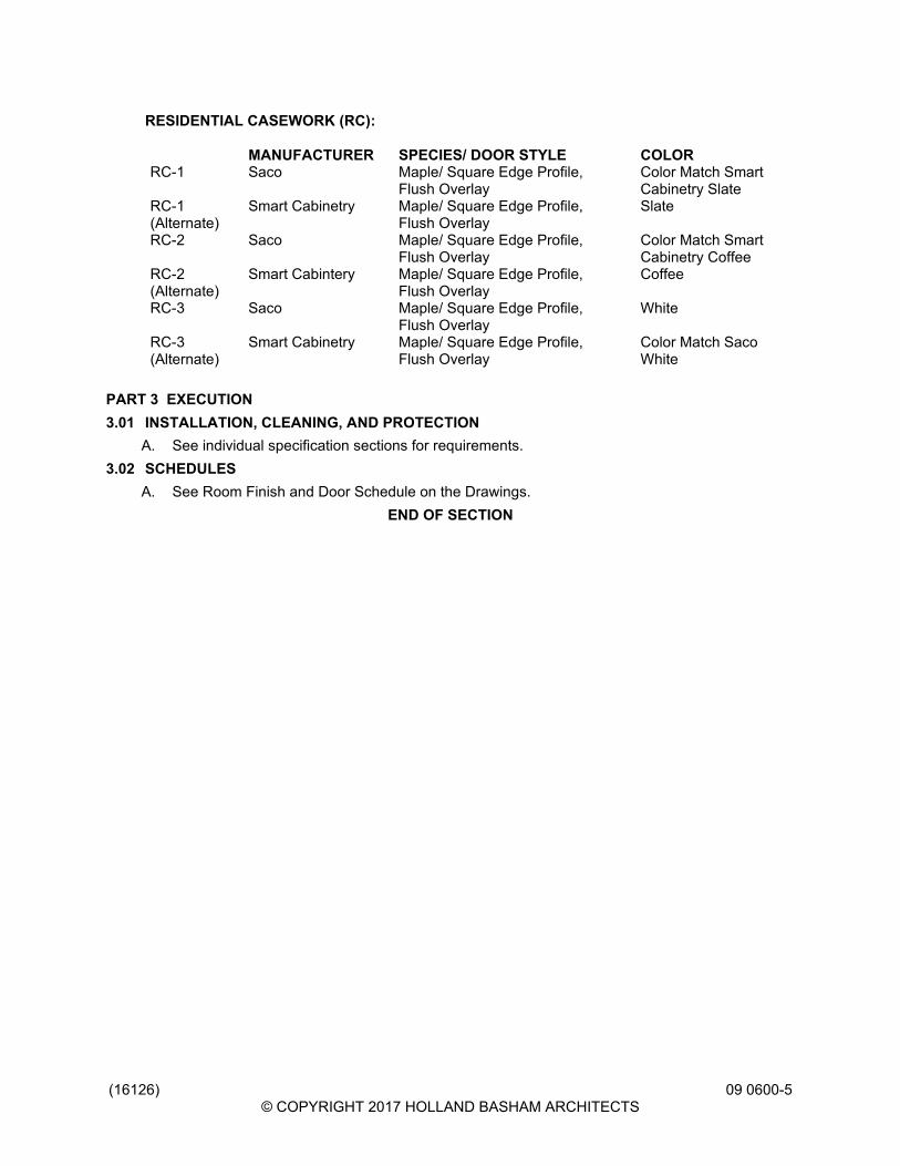
(16126)© COPYRIGHT 2017 HOLLAND BASHAM ARCHITECTS
09 0600-5
RESIDENTIAL CASEWORK (RC):
MANUFACTURER SPECIES/ DOOR STYLE COLORRC-1 Saco Maple/ Square Edge Profile,
Flush OverlayColor Match SmartCabinetry Slate
RC-1(Alternate)
Smart Cabinetry Maple/ Square Edge Profile,Flush Overlay
Slate
RC-2 Saco Maple/ Square Edge Profile,Flush Overlay
Color Match SmartCabinetry Coffee
RC-2(Alternate)
Smart Cabintery Maple/ Square Edge Profile,Flush Overlay
Coffee
RC-3 Saco Maple/ Square Edge Profile,Flush Overlay
White
RC-3(Alternate)
Smart Cabinetry Maple/ Square Edge Profile,Flush Overlay
Color Match SacoWhite
PART 3 EXECUTION3.01 INSTALLATION, CLEANING, AND PROTECTION
A. See individual specification sections for requirements.3.02 SCHEDULES
A. See Room Finish and Door Schedule on the Drawings.END OF SECTION

(16126)© COPYRIGHT 2017 HOLLAND BASHAM ARCHITECTS
09 0600-6
(16126)© COPYRIGHT 2017 HOLLAND BASHAM ARCHITECTS
09 2116-1
SECTION 09 2116GYPSUM BOARD ASSEMBLIES
PART 1 GENERAL1.01 SECTION INCLUDES
A. Performance criteria for gypsum board assemblies.B. Metal stud wall framing.C. Metal channel ceiling framing.D. Acoustic insulation.E. Cementitious backing board.F. Gypsum wallboard.G. Joint treatment and accessories.H. Textured finish system.
1.02 RELATED REQUIREMENTSA. Section 06 1000 - Rough Carpentry: Building framing, wood blocking, and sheathing.B. Section 06 1000 - Rough Carpentry: Building framing and sheathing.C. Section 07 2100 - Thermal Insulation: Acoustic insulation.D. Section 07 2500 - Weather Barriers: Water-resistive barrier over sheathing.E. Section 07 8400 - Firestopping: Top-of-wall assemblies at fire rated walls.F. Section 07 9200 - Joint Sealants: Sealing acoustical gaps in construction other than gypsum
board or plaster work.1.03 REFERENCE STANDARDS
A. ANSI A108.11 - American National Standard for Interior Installation of Cementitious BackerUnits; 2010 (Revised).
B. ANSI A118.9 - American National Standard Specifications for Test Methods and Specificationsfor Cementitious Backer Units; 1999 (Reaffirmed 2010).
C. ASTM C475/C475M - Standard Specification for Joint Compound and Joint Tape for FinishingGypsum Board; 2015.
D. ASTM C645 - Standard Specification for Nonstructural Steel Framing Members; 2014.E. ASTM C665 - Standard Specification for Mineral-Fiber Blanket Thermal Insulation for Light
Frame Construction and Manufactured Housing; 2012.F. ASTM C754 - Standard Specification for Installation of Steel Framing Members to Receive
Screw-Attached Gypsum Panel Products; 2015.G. ASTM C840 - Standard Specification for Application and Finishing of Gypsum Board; 2013.H. ASTM C954 - Standard Specification for Steel Drill Screws for the Application of Gypsum Panel
Products or Metal Plaster Bases to Steel Studs From 0.033 in. (0.84 mm) to 0.112 in. (2.84mm) in Thickness; 2015.
I. ASTM C1002 - Standard Specification for Steel Self-Piercing Tapping Screws for Application ofGypsum Panel Products or Metal Plaster Bases to Wood Studs or Steel Studs; 2014.
J. ASTM C1047 - Standard Specification for Accessories For Gypsum Wallboard and GypsumVeneer Base; 2014a.
K. ASTM C1178/C1178M - Standard Specification for Coated Glass Mat Water-Resistant GypsumBacking Panel; 2013.
L. ASTM C1278/C1278M - Standard Specification for Fiber-Reinforced Gypsum Panel; 2007a(Reapproved 2011).

(16126)© COPYRIGHT 2017 HOLLAND BASHAM ARCHITECTS
09 2116-2
M. ASTM C1288 - Standard Specification for Discrete Non-Asbestos Fiber-Cement InteriorSubstrate Sheets; 2014.
N. ASTM C1325 - Specification for Non-Asbestos Fiber-Mat Reinforced Cementitious BackerUnits; 2014.
O. ASTM C1396/C1396M - Standard Specification for Gypsum Board; 2014.P. ASTM C1658/C1658M - Standard Specification for Glass Mat Gypsum Panels; 2013.Q. ASTM D3273 - Standard Test Method for Resistance to Growth of Mold on the Surface of
Interior Coatings in an Environmental Chamber; 2012.R. ASTM E90 - Standard Test Method for Laboratory Measurement of Airborne Sound
Transmission Loss of Building Partitions and Elements; 2009.S. ASTM E413 - Classification for Rating Sound Insulation; 2010.T. GA-214 - Recommended Levels of Gypsum Board Finish; 2010.U. GA-216 - Application and Finishing of Gypsum Board; 2013.V. GA-234 - Control Joints For Fire-Resistance Rated Systems; Gypsum Association; Gypsum
Association; 2008.W. GA-600 - Fire Resistance Design Manual; 2015.X. UL (FRD) - Fire Resistance Directory; current edition.
1.04 SUBMITTALSA. See Section 01 3000 - Administrative Requirements, for submittal procedures.B. Shop Drawings: Indicate special details associated with fireproofing, acoustic seals, and
control joint layout.C. Product Data: Provide data on metal framing, gypsum board, accessories, and joint finishing
system.D. Product Data: Provide manufacturer's data on partition head to structure connectors, showing
compliance with requirements.E. Test Reports: For stud framing products that do not comply with ASTM C645 or ASTM C754,
provide independent laboratory reports showing maximum stud heights at required spacingsand deflections.
1.05 QUALITY ASSURANCEA. Installer Qualifications: Company specializing in performing gypsum board installation and
finishing, with minimum three years of experience.PART 2 PRODUCTS2.01 GYPSUM BOARD ASSEMBLIES
A. Provide completed assemblies complying with ASTM C840 and GA-216.1. See PART 3 for finishing requirements.
B. Interior Partitions, Indicated as Acoustic: Provide completed assemblies with the followingcharacteristics:1. Acoustic Attenuation: STC as indicated on drawings calculated in accordance with ASTM
E413, based on tests conducted in accordance with ASTM E90.C. Shaft Walls at Elevator Shafts: Provide completed assemblies with the following
characteristics:1. Air Pressure Within Shaft: Intermittent loads of 5 lbf/sq ft with maximum mid-span
deflection of L/240.2. Acoustic Attenuation: STC as indicated on drawings calculated in accordance with ASTM
E413, based on tests conducted in accordance with ASTM E90.D. Fire Rated Assemblies: Provide completed assemblies with the following characteristics:

(16126)© COPYRIGHT 2017 HOLLAND BASHAM ARCHITECTS
09 2116-3
1. As indicated on drawings.2. Gypsum Association File Numbers: Comply with requirements of GA-600 for the
particular assembly.3. UL Assembly Numbers: Provide construction equivalent to that listed for the particular
assembly in the current UL (FRD).2.02 METAL FRAMING MATERIALS
A. Manufacturers - Metal Framing, Connectors, and Accessories:1. Clarkwestern Dietrich Building Systems LLC: www.clarkdietrich.com.2. Marino: www.marinoware.com.3. MRI Steel Framing : www.mristeelframing.com.4. Phillips Manufacturing Company: www.phillipsmfg.com.5. Substitutions: See Section 01 6000 - Product Requirements.
B. Non-Loadbearing Framing System Components: 1; galvanized sheet steel, of size andproperties necessary to comply with 2 for the spacing indicated, with maximum deflection ofwall framing of L/240 at 5 psf.1. Studs: "C" shaped with flat or formed webs with knurled faces.2. Runners: U shaped, sized to match studs.3. Ceiling Channels: C-shaped.4. Furring: Hat-shaped sections, minimum depth of 7/8 inch.5. Resilient Furring Channels: 1/2 inch depth, for attachment to substrate through one leg
only.a. Products:
1) Same manufacturer as other framing materials.2) Substitutions: See Section 01 6000 - Product Requirements.
C. Loadbearing Studs for Application of Gypsum Board: As indicated on the drawings.D. Shaft Wall Studs and Accessories: ASTM C645; galvanized sheet steel, of size and properties
necessary to comply with ASTM C754 and specified performance requirements.E. Ceiling Hangers: Type and size as specified in ASTM C754 for spacing required.F. Partition Head To Structure Connections: Provide track fastened to structure with legs of
sufficient length to accommodate deflection, for friction fit of studs cut short.1. See the Gypsum Association’s Fire Resistance Design Manual (GA-600) Figure 8
Perimeter Relief Details for steel stud partition.2.03 BOARD MATERIALS
A. Manufacturers - Gypsum-Based Board:1. American Gypsum Company; ____: www.americangypsum.com.2. CertainTeed Corporation; ____: www.certainteed.com.3. Georgia-Pacific Gypsum; ____: www.gpgypsum.com.4. National Gypsum Company; ____: www.nationalgypsum.com.5. USG Corporation; ____: www.usg.com.6. Substitutions: See Section 01 6000 - Product Requirements.
B. Gypsum Wallboard: Paper-faced gypsum panels as defined in ASTM C1396/C1396M; sizes tominimize joints in place; ends square cut.1. Application: Use for vertical surfaces and ceilings, unless otherwise indicated.2. Glass mat faced gypsum panels as defined in ASTM C1658/C1658M, suitable for paint
finish, of the same core type and thickness must be used at mold-resistant locations andmay be substituted for paper-faced board.
3. Unfaced fiber-reinforced gypsum panels as defined in ASTM C1278/C1278M, suitable forpaint finish, of the same core type and thickness must be used at mold-resistant locationsand may be substituted for paper-faced board.
4. Mold Resistance: Score of 10, when tested in accordance with ASTM D3273.

(16126)© COPYRIGHT 2017 HOLLAND BASHAM ARCHITECTS
09 2116-4
a. Use glass-mat-faced gypsum panels, unfaced fiber-reinforced gypsum panels, or______.
b. Mold-resistant board is required whenever board is being installed before the buildingis enclosed and conditioned.
c. Mold resistant board is required at exterior walls, plumbing walls in toilets, and otherwet locations.
5. At Assemblies Indicated with Fire-Rating: Use type required by indicated testedassembly; if no tested assembly is indicated, use Type X board, UL or WH listed.
6. Thickness: a. Single-Layer Assemblies: Thicknesses as indicated on drawings.
7. Paper-Faced Products:a. American Gypsum Company; LightRoc Gypsum Wallboard.b. Georgia-Pacific Gypsum; ToughRock.c. National Gypsum Company; Gold Bond Brand Gypsum Wallboard.d. USG Corporation; Sheetrock Brand Gypsum Panels.e. Substitutions: See Section 01 6000 - Product Requirements.
8. Glass Mat Faced Products:a. Georgia-Pacific Gypsum; DensArmor Plus.b. National Gypsum Company; Gold Bond eXP Interior Extreme Gypsum Panel.c. USG Corporation; USG Sheetrock Brand Glass-Mat Panels Mold Tough.d. Substitutions: See Section 01 6000 - Product Requirements.
9. Unfaced Products:a. USG Corporation; Fiberock Aqua-Tough Interior Panels.b. Substitutions: See Section 01 6000 - Product Requirements.
C. Backing Board For Wet Areas: One of the following products:1. Application: Surfaces behind tile in wet areas including tub and shower surrounds and
shower ceilings.2. Mold Resistance: Score of 10, when tested in accordance with ASTM D3273.3. ANSI Cement-Based Board: Non-gypsum-based; aggregated Portland cement panels
with glass fiber mesh embedded in front and back surfaces complying with ANSI A118.9or ASTM C1325.a. Thickness: As indicated on drawings.b. Products:
1) National Gypsum Company; PermaBase Cement Board: www.nationalgypsum.com.
2) USG Corporation; Durock Brand Cement Board: www.usg.com.3) Substitutions: See Section 01 6000 - Product Requirements.
4. ASTM Cement-Based Board: Non-gypsum-based, cementitious board complying withASTM C1288.a. Thickness: As indicated on drawings.b. Products:
1) James Hardie Building Products, Inc; HardieBacker Cement Board: www.jameshardie.com.
2) Substitutions: See Section 01 6000 - Product Requirements.5. Glass Mat Faced Board: Coated glass mat water-resistant gypsum backing panel as
defined in ASTM C1178/C1178M.a. Thickness: As indicated on drawings.b. Products:
1) Georgia-Pacific Gypsum; DensShield Tile Backer.2) National Gypsum Company; Gold Bond eXP Tile Backer.3) Substitutions: See Section 01 6000 - Product Requirements.
D. Ceiling Board: Special sag resistant gypsum ceiling board as defined in ASTM C1396/C1396M;sizes to minimize joints in place; ends square cut.
(16126)© COPYRIGHT 2017 HOLLAND BASHAM ARCHITECTS
09 2116-5
1. Application: Ceilings, soffits, bulkheads and other horizontal interior applications, unlessotherwise indicated.
2. Thickness: As indicated on drawings.3. Edges: Tapered.4. Products:
a. Georgia-Pacific Gypsum; ToughRock Span 24 Ceiling Board.b. National Gypsum Company; High Strength Brand Ceiling Board.c. USG Corporation; Sheetrock Brand Sag-Resistant Interior Gypsum Ceiling Board.d. Substitutions: See Section 01 6000 - Product Requirements.
E. Exterior Sheathing Board: As specified in Section 06 1000.F. Shaftwall and Coreboard: Type X; 1 inch thick by 24 inches wide, beveled long edges, ends
square cut.1. Glass Mat Faced Type: Glass mat shaftliner gypsum panel or glass mat coreboard
gypsum panel as defined in ASTM C1658/C1658M.2. Products:
a. Georgia-Pacific Gypsum; DensGlass Shaftliner (mold-resistant).b. Substitutions: See Section 01 6000 - Product Requirements.
2.04 ACCESSORIESA. Acoustic Insulation: ASTM C665; preformed glass fiber, friction fit type, unfaced. Thickness:
as indicated on the drawings.B. Acoustic Sealant: Acrylic emulsion latex or water-based elastomeric sealant; do not use
solvent-based non-curing butyl sealant.C. Water-Resistive Barrier: As specified in Section 07 2500.D. Finishing Accessories: ASTM C1047, galvanized steel or rolled zinc, unless noted otherwise.
1. Types: As detailed or required for finished appearance.2. Products:
a. Same manufacturer as framing materials.b. Substitutions: See Section 01 6000 - Product Requirements.
3. Corner Beads: ASTM C1047; Galvanized steel.4. Edge Trim: ASTM C1047; LC bead, as defined in ASTM C 840.5. Expansion (Control) Joint: ASTM C1047; One-piece, rolled zinc with V-shaped slot and
removable strip covering slot opening.E. Joint Materials: ASTM C475/C475M and as recommended by gypsum board manufacturer for
project conditions.1. Tape: 2 inch wide, creased paper tape for joints and corners, except as otherwise
indicated.2. Ready-mixed vinyl-based joint compound.
F. High Build Drywall Surfacer: Vinyl acrylic latex-based coating for spray application, designed totake the place of skim coating and separate paint primer in achieving Level 5 finish.
G. Textured Finish Materials: Latex-based compound; plain. H. Screws for Fastening of Gypsum Panel Products to Cold-Formed Steel Studs Less than 0.033
inch in Thickness and Wood Members: ASTM C1002; self-piercing tapping screws, corrosionresistant.
I. Screws for Fastening of Gypsum Panel Products to Steel Members from 0.033 to 0.112 inch inThickness: ASTM C954; steel drill screws, corrosion resistant.
J. Anchorage to Substrate: Tie wire, nails, screws, and other metal supports, of type and size tosuit application; to rigidly secure materials in place.

(16126)© COPYRIGHT 2017 HOLLAND BASHAM ARCHITECTS
09 2116-6
PART 3 EXECUTION3.01 EXAMINATION
A. Verify that project conditions are appropriate for work of this section to commence.3.02 SHAFT WALL INSTALLATION
A. Shaft Wall Framing: Install in accordance with manufacturer's installation instructions.1. Fasten runners to structure with short leg to finished side, using appropriate power-driven
fasteners at not more than 24 inches on center.2. Install studs at spacing required to meet performance requirements.
B. Shaft Wall Liner: Cut panels to accurate dimension and install sequentially between specialfriction studs. 1. On walls over sixteen feet high, screw-attach studs to runners top and bottom.2. Seal perimeter of shaft wall and penetrations with firestopping sealant.
3.03 FRAMING INSTALLATIONA. Metal Framing: Install in accordance with ASTM C754 and manufacturer's instructions.B. Suspended Ceilings and Soffits: Space framing and furring members as indicated.C. Studs: Space studs at 16 inches on center.
1. Extend partition framing as indicated on drawings.2. Partitions Terminating at Structure: Attach extended leg top runner to structure, maintain
clearance between top of studs and structure, and brace both flanges of studs withcontinuous bridging.
D. Openings: Reinforce openings as required for weight of doors or operable panels, using notless than double studs at jambs.
E. Standard Wall Furring: Install at concrete walls scheduled to receive gypsum board, not morethan 4 inches from floor and ceiling lines and abutting walls. Secure in place on alternatechannel flanges at maximum 24 inches on center.1. Orientation: Horizontal.2. Spacing: As indicated.
F. Acoustic Furring: Install resilient channels at maximum 24 inches on center. Locate joints overframing members.
G. Blocking: Install wood blocking or mechanically fastened sheet steel strapping for support of:1. Framed openings.2. Wall mounted cabinets.3. Toilet accessories.4. Wall mounted door hardware.5. __________6. Other items indicated.
3.04 ACOUSTIC ACCESSORIES INSTALLATIONA. Acoustic Insulation: Place tightly within spaces, around cut openings, behind and around
electrical and mechanical items within partitions, and tight to items passing through partitions.B. Acoustic Sealant: Install in accordance with manufacturer's instructions.
1. Place continuous bead at perimeter of each layer of gypsum board.2. Seal around all penetrations by conduit, pipe, ducts, and rough-in boxes, except where
firestopping is provided.3.05 BOARD INSTALLATION
A. Comply with ASTM C840, GA-216, and manufacturer's instructions. Install to minimize butt endjoints, especially in highly visible locations.
B. Single-Layer Non-Rated: Install gypsum board in most economical direction, with ends andedges occurring over firm bearing.

(16126)© COPYRIGHT 2017 HOLLAND BASHAM ARCHITECTS
09 2116-7
C. Double-Layer Non-Rated: Use gypsum board for first layer, placed perpendicular to framing orfurring members, with ends and edges occurring over firm bearing. Use glass mat facedgypsum board at exterior walls and at other locations as indicated. Place second layer parallelto framing or furring members. Offset joints of second layer from joints of first layer.
D. Fire-Rated Construction: Install gypsum board in strict compliance with requirements ofassembly listing.
E. Cementitious Backing Board: Install over steel framing members and plywood substrate whereindicated, in accordance with ANSI A108.11 and manufacturer's instructions.
F. Installation on Metal Framing: Use screws for attachment of gypsum board except face layer ofnon-rated double-layer assemblies, which may be installed by means of adhesive lamination.
G. Installation on Wood Framing: For rated assemblies, comply with requirements of listingauthority. For non-rated assemblies, install as follows:1. Single-Layer Applications: Screw attachment.
3.06 INSTALLATION OF TRIM AND ACCESSORIESA. Control Joints: Place control joints consistent with lines of building spaces and as indicated.
1. Control Joints shall be either manufactured devices designed for this purpose or fieldfabricated from suitable materials.
2. Locate control joints according to the criteria listed below and as shown on the drawings.3. Control joints in the gypsum board shall be provided where any of the conditions
described below exist:a. Where a partition, wall, or ceiling traverses a construction joint (expansion, seismic,
or building control element) in the building structure.b. A control joint or intermediate blocking shall be installed where ceiling framing
members change direction.c. Not more than 30 feet apart on walls running in an uninterrupted straight plane over
30 feet long.d. At interior ceilings with perimeter relief, not more than 50 feet apart in both directions.e. At interior ceilings without perimeter relief, not more than 30 feet apart in both
directions.f. At gypsum board partitions above all door frames which are not full height, at the
corners on both sides of the wall. Control joints at one or both corners may beomitted if the door frame corner is located at the intersection of partitions.
g. Full height door frames shall be considered equivalent to a control joint.h. At locations specified by the architect or designer where a control joint is incorporated
as a design accent or architectural feature.i. Where a control joint occurs in an acoustical or fire-rated system, blocking shall be
provided behind the control joint by using a backing material such as 5/8" type Xgypsum board, mineral fiber or other tested equivalent. See the GypsumAssociation’s Fire Resistance Design Manual (GA-600) or SpecialRecommendations: Control Joints for Fire-Resistance Rated Systems (GA-234).
B. Corner Beads: Install at external corners, using longest practical lengths. C. Edge Trim: Install at locations where gypsum board abuts dissimilar materials and as
indicated.3.07 JOINT TREATMENT
A. Paper Faced Gypsum Board: Use paper joint tape, bedded with ready-mixed vinyl-based jointcompound and finished with ready-mixed vinyl-based joint compound.
B. Finish gypsum board in accordance with levels defined in ASTM C840 and GA-214 as follows:1. Level 5: Walls and ceilings to receive semi-gloss or gloss paint finish, walls "washed" by
light fixtures or natural light and other areas specifically indicated.2. Level 4: Walls and ceilings to receive paint finish or wall coverings, unless otherwise
indicated as level 5.
(16126)© COPYRIGHT 2017 HOLLAND BASHAM ARCHITECTS
09 2116-8
3. Level 1: Wall areas above finished ceilings, whether or not accessible in the completedconstruction.
4. Level 0: Temporary partitions.C. Tape, fill, and sand exposed joints, edges, and corners to produce smooth surface ready to
receive finishes.1. Feather coats of joint compound so that camber is maximum 1/32 inch.
D. Where level 5 finish is indicated or at glass mat faced gypsum board indicated to receive alevel 4 or 5 finish, spray apply high build drywall surfacer over entire surface after joints havebeen properly treated; achieve a flat and tool mark-free finish.
3.08 TEXTURE FINISHA. Apply finish texture coating by means of spraying apparatus in accordance with manufacturer's
instructions and to match approved sample.B. Texture Required: Perfect Spray Fine by Gold Bond or equal.
3.09 TOLERANCESA. Maximum Variation of Finished Gypsum Board Surface from True Flatness: 1/8 inch in 10 feet
in any direction.END OF SECTION

(16126)© COPYRIGHT 2017 HOLLAND BASHAM ARCHITECTS
09 3000-1
SECTION 09 3000TILING
PART 1 GENERAL1.01 SECTION INCLUDES
A. Tile for floor applications.B. Tile for wall applications.C. Non-ceramic trim.
1.02 RELATED REQUIREMENTSA. Section 09 0600 - Color Schedule: Tile manufacturer, style/color/finish and size and Grout
manufacturer, color and location.1.03 REFERENCE STANDARDS
A. ANSI A108/A118/A136.1 - American National Standard Specifications for the Installation ofCeramic Tile (Compendium); 2013.1.
B. ANSI A108.1a - American National Standard Specifications for Installation of Ceramic Tile inthe Wet-Set Method, with Portland Cement Mortar; 2014.
C. ANSI A108.1b - American National Standard Specifications for Installation of Ceramic Tile on aCured Portland Cement Mortar Setting Bed with Dry-Set or Latex-Portland Cement Mortar;1999 (Reaffirmed 2010).
D. ANSI A108.1c - Specifications for Contractors Option: Installation of Ceramic Tile in theWet-Set Method with Portland Cement Mortar or Installation of Ceramic Tile on a CuredPortland Cement Mortar Bed with Dry-Set or Latex-Portland Cement; 1999 (Reaffirmed 2010).
E. ANSI A108.4 - American National Standard Specifications for Installation of Ceramic Tile withOrganic Adhesives or Water Cleanable Tile-Setting Epoxy Adhesive; 2009 (Revised).
F. ANSI A108.5 - American National Standard Specifications for Installation of Ceramic Tile withDry-Set Portland Cement Mortar or Latex-Portland Cement Mortar; 1999 (Reaffirmed 2010).
G. ANSI A108.6 - American National Standard Specifications for Installation of Ceramic Tile withChemical Resistant, Water Cleanable Tile-Setting and -Grouting Epoxy; 1999 (Reaffirmed2010).
H. ANSI A108.8 - American National Standard Specifications for Installation of Ceramic Tile withChemical Resistant Furan Resin Mortar and Grout; 1999 (Reaffirmed 2010).
I. ANSI A108.9 - American National Standard Specifications for Installation of Ceramic Tile withModified Epoxy Emulsion Mortar/Grout; 1999 (Reaffirmed 2010).
J. ANSI A108.10 - American National Standard Specifications for Installation of Grout in Tilework;1999 (Reaffirmed 2010).
K. ANSI A108.11 - American National Standard for Interior Installation of Cementitious BackerUnits; 2010 (Revised).
L. ANSI A108.12 - American National Standard for Installation of Ceramic Tile with EGP (Exteriorglue plywood) Latex-Portland Cement Mortar; 1999 (Reaffirmed 2010).
M. ANSI A108.13 - American National Standard for Installation of Load Bearing, Bonded,Waterproof Membranes for Thin-Set Ceramic Tile and Dimension Stone; 2005 (Reaffirmed2010).
N. ANSI A118.1 - American National Standard Specifications for Dry-Set Cement Mortar; 2012(Revised).
O. ANSI A118.3 - American National Standard Specifications for Chemical Resistant, WaterCleanable Tile-Setting and -Grouting Epoxy and Water Cleanable Tile-Setting Epoxy Adhesive;2013 (Revised).

(16126)© COPYRIGHT 2017 HOLLAND BASHAM ARCHITECTS
09 3000-2
P. ANSI A118.4 - American National Standard Specifications for Modified Dry-Set Cement Mortar;2012 (Revised).
Q. ANSI A118.7 - American National Standard Specifications for High Performance CementGrouts for Tile Installation; 2010 (Revised).
R. ANSI A118.10 - American National Standard Specifications for Load Bearing, Bonded,Waterproof Membranes For Thin-Set Ceramic Tile And Dimension Stone Installation; 2014.
S. ANSI A137.1 - American National Standard Specifications for Ceramic Tile; 2013.1.T. ISO 13007 - International Standards Organization; classification for Grout and Adhesives;
current edition.U. TCNA (HB) - Handbook for Ceramic, Glass, and Stone Tile Installation; 2015.
1.04 SUBMITTALSA. See Section 01 3000 - Administrative Requirements, for submittal procedures.B. Product Data: Provide manufacturers' data sheets on tile, mortar, grout, and accessories.
Include instructions for using grouts and adhesives.C. Shop Drawings: Indicate tile layout, patterns, color arrangement, perimeter conditions,
junctions with dissimilar materials, control and expansion joints, thresholds, ceramicaccessories, and setting details.
D. Manufacturer's Certificate: Certify that products meet or exceed specified requirements.E. Maintenance Data: Include recommended cleaning methods, cleaning materials, and stain
removal methods.F. Maintenance Materials: Furnish the following for Owner's use in maintenance of project.
1. See Section 01 6000 - Product Requirements, for additional provisions.2. Extra Tile: 2 percent of each size, color, and surface finish combination.
1.05 QUALITY ASSURANCEA. Maintain one copy of and ANSI A108/A118/A136.1 and TCNA (HB) on site.B. Installer Qualifications: Company specializing in performing tile installation, with minimum of
five years of documented experience.1.06 DELIVERY, STORAGE, AND HANDLING
A. Protect adhesives from freezing or overheating in accordance with manufacturer's instructions.1.07 FIELD CONDITIONS
A. Do not install solvent-based products in an unventilated environment.PART 2 PRODUCTS2.01 TILE
A. Manufacturers: 1. See Section 09 0600 - Color Schedule.2. Other Acceptable Manufacturers:
a. American Olean Corporation: www.americanolean.com.b. Dal-Tile Corporation: www.daltile.com.c. Summitville Tiles, Inc: www.summitville.com.
B. Ceramic Mosaic Tile, Type CMT: ANSI A137.1, standard grade.1. Color(s): See Section 09 0600 - Color Schedule.
C. Glazed Wall Tile, Type CT: ANSI A137.1, standard grade.1. Color(s): See Section 09 0600 - Color Schedule.
D. Porcelain Tile, Type PT: ANSI A137.1, standard grade.1. Color(s): See Section 09 0600 - Color Schedule.
(16126)© COPYRIGHT 2017 HOLLAND BASHAM ARCHITECTS
09 3000-3
2.02 TRIM AND ACCESSORIESA. Ceramic Trim: Matching surface bullnose, double bullnose, and cove base ceramic shapes in
sizes coordinated with field tile.1. Applications:
a. Outside Corners: Surface Bullnose.b. Inside Corners: Butted.c. Floor to Wall Joints: Cove base.
2. Manufacturers: Same as for tile.B. Non-Ceramic Trim: Satin brass anodized extruded aluminum, style and dimensions to suit
application, for setting using tile mortar or adhesive.1. Manufacturers:
a. Schluter-Systems: www.schluter.com.2.03 SETTING MATERIALS
A. Manufacturers:1. Bostik Inc: www.bostik-us.com.2. Custom Building Products: www.custombuildingproducts.com.3. LATICRETE International, Inc: www.laticrete.com.4. Merkrete, by Parex USA, Inc: www.merkrete.com.5. Substitutions: See Section 01 6000 - Product Requirements.
B. Latex-Portland Cement Mortar Bond Coat: ANSI A118.4 and ISO 13007 Classification C2ES2.C. Dry-Set Portland Cement Mortar Bond Coat: ANSI A118.1 and ISO 13007 Classification C1.
2.04 GROUTSA. Manufacturers:
1. Bonsal American, Inc: www.bonsalamerican.com.2. Bostik Inc: www.bostik-us.com.3. Custom Building Products: www.custombuildingproducts.com.4. LATICRETE International, Inc: www.laticrete.com.5. MAPEI Corporation: www.mapei.us.6. Substitutions: Not permitted.
B. Polymer Modified Grout: ANSI A118.7 and ISO 13007 Classification CG2WAF, polymermodified cement grout.1. Applications: Use this type of grout where indicated and where no other type of grout is
indicated.2. Use sanded grout for joints 1/8 inch wide and larger; use unsanded grout for joints less
than 1/8 inch wide.3. Color(s): See Section 09 0600 - Color Schedule.
C. Epoxy Grout: ANSI A118.3 and ISO 13007 Classification RG, chemical resistant andwater-cleanable epoxy grout.1. Color(s): See Section 09 0600 - Color Schedule.
2.05 ACCESSORY MATERIALSA. Waterproofing Membrane at Floors: Specifically designed for bonding to cementitious
substrate under thick mortar bed or thin-set tile; complying with ANSI A118.10.1. Fluid or Trowel Applied Type:
a. Material: Acrylic.b. Products:
1) ARDEX Engineered Cements: www.ardexamericas.com.2) AVM Industries, Inc with continuous polyester fabric reinforcement:
www.avmindustries.com.3) Substitutions: See Section 01 6000 - Product Requirements.
(16126)© COPYRIGHT 2017 HOLLAND BASHAM ARCHITECTS
09 3000-4
PART 3 EXECUTION3.01 EXAMINATION
A. Verify that sub-floor surfaces are smooth and flat within the tolerances specified for that type ofwork and are ready to receive tile.
B. Verify that wall surfaces are smooth and flat within the tolerances specified for that type ofwork, are dust-free, and are ready to receive tile.
C. Verify that sub-floor surfaces are dust-free and free of substances that could impair bonding ofsetting materials to sub-floor surfaces.
D. Verify that required floor-mounted utilities are in correct location.3.02 PREPARATION
A. Protect surrounding work from damage.B. Vacuum clean surfaces and damp clean.C. Seal substrate surface cracks with filler. Level existing substrate surfaces to acceptable
flatness tolerances.3.03 INSTALLATION - GENERAL
A. Install tile, thresholds, and stair treads and grout in accordance with applicable requirements ofANSI A108.1a through ANSI A108.13, manufacturer's instructions, and TCNA (HB)recommendations.
B. Lay tile to pattern indicated. Do not interrupt tile pattern through openings.C. Cut and fit tile to penetrations through tile, leaving sealant joint space. Form corners and bases
neatly. Align floor joints.D. Place tile joints uniform in width, subject to variance in tolerance allowed in tile size. Make
grout joints without voids, cracks, excess mortar or excess grout, or too little grout.E. Form internal angles square and external angles square.F. Install non-ceramic trim in accordance with manufacturer's instructions.G. Sound tile after setting. Replace hollow sounding units.H. Keep control and expansion joints free of mortar, grout, and adhesive.I. Provide control joints as follows:
1. Where a change of substrate occurs.2. Where a control joint in the substrate occurs.3. Where indicated.
J. Prior to grouting, allow installation to completely cure; minimum of 48 hours.K. Grout tile joints unless otherwise indicated. Use standard grout unless otherwise indicated.L. At changes in plane and tile-to-tile control joints, use tile sealant instead of grout, with either
bond breaker tape or backer rod as appropriate to prevent three-sided bonding.3.04 INSTALLATION - FLOORS - THIN-SET METHODS
A. Over interior concrete substrates, install in accordance with TCNA (HB) Method F113, dry-setor latex-Portland cement bond coat, with standard grout, unless otherwise indicated.
3.05 INSTALLATION - WALL TILEA. Over gypsum wallboard on wood or metal studs install in accordance with TCNA (HB) Method
W243, thin-set with dry-set or latex-Portland cement bond coat, unless otherwise indicated.3.06 CLEANING
A. Clean tile and grout surfaces.
(16126)© COPYRIGHT 2017 HOLLAND BASHAM ARCHITECTS
09 3000-5
3.07 PROTECTIONA. Do not permit traffic over finished floor surface for 4 days after installation.
END OF SECTION

(16126)© COPYRIGHT 2017 HOLLAND BASHAM ARCHITECTS
09 3000-6
(16126)© COPYRIGHT 2017 HOLLAND BASHAM ARCHITECTS
09 5100-1
SECTION 09 5100ACOUSTICAL CEILINGS
PART 1 GENERAL1.01 SECTION INCLUDES
A. Suspended metal grid ceiling system.B. Acoustical units.
1.02 RELATED REQUIREMENTSA. Section 09 0600 - Color Schedule: Acoustical ceiling panels and grid, manufacturer, style,
color and size.1.03 REFERENCE STANDARDS
A. ASTM C635/C635M - Standard Specification for the Manufacture, Performance, and Testing ofMetal Suspension Systems for Acoustical Tile and Lay-in Panel Ceilings; 2013a.
B. ASTM E1264 - Standard Classification for Acoustical Ceiling Products; 2014.1.04 ADMINISTRATIVE REQUIREMENTS
A. Sequence work to ensure acoustical ceilings are not installed until building is enclosed,sufficient heat is provided, dust generating activities have terminated, and overhead work iscompleted, tested, and approved.
B. Do not install acoustical units until after interior wet work is dry.1.05 SUBMITTALS
A. See Section 01 3000 - Administrative Requirements, for submittal procedures.B. Product Data: Provide data on suspension system components and acoustical units.C. Samples: Submit two samples 4 by 4 inch in size illustrating material and finish of acoustical
units.D. Samples: Submit two samples each, 10 inches long, of suspension system main runner.E. Manufacturer's Installation Instructions: Indicate special procedures.F. Maintenance Materials: Furnish the following for Owner's use in maintenance of project.
1. See Section 01 6000 - Product Requirements, for additional provisions.2. Extra Acoustical Units: Quantity equal to 12 percent of total installed, or nearest full
carton.1.06 QUALITY ASSURANCE
A. Suspension System Manufacturer Qualifications: Company specializing in manufacturing theproducts specified in this section with minimum five years documented experience.
B. Acoustical Unit Manufacturer Qualifications: Company specializing in manufacturing theproducts specified in this section with minimum five years documented experience.
1.07 FIELD CONDITIONSA. Maintain uniform temperature of minimum 60 degrees F, and maximum humidity of 40 percent
prior to, during, and after acoustical unit installation.PART 2 PRODUCTS2.01 MANUFACTURERS
A. Acoustic Tiles/Panels:1. Armstrong World Industries, Inc: www.armstrong.com.2. CertainTeed Corporation: www.certainteed.com.3. USG: www.usg.com.4. Substitutions: See Section 01 6000 - Product Requirements.
B. Suspension Systems:

(16126)© COPYRIGHT 2017 HOLLAND BASHAM ARCHITECTS
09 5100-2
1. Same as for acoustical units.2. Substitutions: See Section 01 6000 - Product Requirements.
2.02 ACOUSTICAL UNITSA. Acoustical Units - General: ASTM E1264, Class A.B. Acoustical Panels Type APC-1: Painted mineral fiber, ASTM E 1264 Type III, with the following
characteristics:1. Thickness: 3/4 inches.2. Composition: Wet felted.3. Light Reflectance: 90 percent, determined in accordance with ASTM E1264.4. NRC Range:.4 to.6, determined in accordance with ASTM E1264.5. Ceiling Attenuation Class (CAC): 40, determined in accordance with ASTM E1264.6. Edge: Square.7. Surface Pattern: Non-directional fissured.8. Suspension System: Exposed grid Type GRID-1.9. Product: See Section 09 0600 - Color Schedule.
2.03 SUSPENSION SYSTEM(S)A. Suspension Systems - General: Complying with ASTM C635/C635M; die cut and interlocking
components, with stabilizer bars, clips, splices, perimeter moldings, and hold down clips asrequired.
B. Exposed Steel Suspension System Type GRID-1: Formed steel, commercial quality coldrolled; heavy-duty.1. Construction: Double web.2. Product: See Section 09 0600 - Color Schedule.
2.04 ACCESSORIESA. Support Channels and Hangers: Galvanized steel; size and type to suit application, seismic
requirements, and ceiling system flatness requirement specified.B. Perimeter Moldings: Same material and finish as grid.
1. At Exposed Grid: Provide L-shaped molding for mounting at same elevation as face ofgrid.a. Edge Trim Fascia: Metal, same finish as grid, see Section 09 0600 - Color Schedule.
C. Acoustical Sealant For Perimeter Moldings: Non-hardening, non-skinning, for use inconjunction with suspended ceiling system.
D. Touch-up Paint: Type and color to match acoustical and grid units.PART 3 EXECUTION3.01 EXAMINATION
A. Verify existing conditions before starting work.B. Verify that layout of hangers will not interfere with other work.
3.02 INSTALLATION - SUSPENSION SYSTEMA. Rigidly secure system, including integral mechanical and electrical components, for maximum
deflection of 1:360.B. Install after major above-ceiling work is complete. Coordinate the location of hangers with
other work.C. Hang suspension system independent of walls, columns, ducts, pipes and conduit. Where
carrying members are spliced, avoid visible displacement of face plane of adjacent members.D. Where ducts or other equipment prevent the regular spacing of hangers, reinforce the nearest
affected hangers and related carrying channels to span the extra distance.E. Do not support components on main runners or cross runners if weight causes total dead load
to exceed deflection capability.

(16126)© COPYRIGHT 2017 HOLLAND BASHAM ARCHITECTS
09 5100-3
F. Support fixture loads using supplementary hangers located within 6 inches of each corner, orsupport components independently.
G. Do not eccentrically load system or induce rotation of runners.H. Perimeter Molding: Install at intersection of ceiling and vertical surfaces and at junctions with
other interruptions.1. Install in bed of acoustical sealant.2. Use longest practical lengths.3. Overlap and rivet corners.
3.03 INSTALLATION - ACOUSTICAL UNITSA. Install acoustical units in accordance with manufacturer's instructions.B. Fit acoustical units in place, free from damaged edges or other defects detrimental to
appearance and function.C. Fit border trim neatly against abutting surfaces.D. Install units after above-ceiling work is complete.E. Install acoustical units level, in uniform plane, and free from twist, warp, and dents.F. Cutting Acoustical Units:
1. Cut to fit irregular grid and perimeter edge trim.2. Make field cut edges of same profile as factory edges.
3.04 TOLERANCESA. Maximum Variation from Flat and Level Surface: 1/8 inch in 10 feet.B. Maximum Variation from Plumb of Grid Members Caused by Eccentric Loads: 2 degrees.
END OF SECTION

(16126)© COPYRIGHT 2017 HOLLAND BASHAM ARCHITECTS
09 5100-4

(16126)© COPYRIGHT 2017 HOLLAND BASHAM ARCHITECTS
09 6500-1
SECTION 09 6500RESILIENT FLOORING
PART 1 GENERAL1.01 SECTION INCLUDES
A. Resilient sheet flooring.B. Resilient tile flooring.C. Resilient base.D. Resilient stair accessories.E. Installation accessories.
1.02 RELATED REQUIREMENTSA. Section 03 3000 - Cast-in-Place Concrete: Restrictions on curing compounds for concrete
slabs and floors.B. Section 09 0600 - Color Schedule: Resilient Flooring and Base manufacturer, style, color and
size.1.03 REFERENCE STANDARDS
A. ASTM E648 - Standard Test Method for Critical Radiant Flux of Floor-Covering Systems Usinga Radiant Heat Energy Source; 2014c.
B. ASTM F970 - Standard Test Method for Static Load Limit; 2007 (Reapproved 2011).C. ASTM F1066 - Standard Specification for Vinyl Composition Floor Tile; 2004 (Reapproved
2014).D. ASTM F1303 - Standard Specification for Sheet Vinyl Floor Covering with Backing; 2004
(Reapproved 2014).E. ASTM F1700 - Standard Specification for Solid Vinyl Tile; 2013a.F. ASTM F1859 - Standard Specification for Rubber Sheet Floor Covering Without Backing; 2014.G. ASTM F1913 - Standard Specification for Vinyl Sheet Floor Covering Without Backing; 2004
(Reapproved 2014).H. NFPA 253 - Standard Method of Test for Critical Radiant Flux of Floor Covering Systems Using
a Radiant Heat Energy Source; 2015.1.04 SUBMITTALS
A. See Section 01 3000 - Administrative Requirements, for submittal procedures.B. Product Data: Provide data on specified products, describing physical and performance
characteristics; including sizes, patterns and colors available; and installation instructions.C. Verification Samples: Submit two samples, 6 by 6 inch in size illustrating color and pattern for
each resilient flooring product specified.D. Certification: Prior to installation of flooring, submit written certification by flooring manufacturer
and adhesive manufacturer that condition of sub-floor is acceptable.E. Maintenance Data: Include maintenance procedures, recommended maintenance materials,
and suggested schedule for cleaning, stripping, and re-waxing.F. Maintenance Materials: Furnish the following for Owner's use in maintenance of project.
1. See Section 01 6000 - Product Requirements, for additional provisions.1.05 FIELD CONDITIONS
A. Store materials for not less than 48 hours prior to installation in area of installation at atemperature of 70 degrees F to achieve temperature stability. Thereafter, maintain conditionsabove 55 degrees F.

(16126)© COPYRIGHT 2017 HOLLAND BASHAM ARCHITECTS
09 6500-2
PART 2 PRODUCTS2.01 SHEET FLOORING
A. Vinyl Sheet Flooring - Type SV-1: Homogeneous without backing, with color and patternthroughout full thickness.1. Minimum Requirements: Comply with ASTM F1913.2. Critical Radiant Flux (CRF): Minimum 0.45 watt per square centimeter, when tested in
accordance with ASTM E 648 or NFPA 253.3. Total Thickness (Wear Layer Thickness): 0.080 inch nominal.4. Sheet Width: 49 inch minimum.5. Static Load Resistance: 250 psi minimum, when tested as specified in ASTM F970.6. Seams: Heat welded.7. Pattern: See Section 09 0600 - Color Schedule.
B. Rubber Sheet Flooring - Type RF-1: 100 percent rubber composition, color and patternthrough total thickness.1. Minimum Requirements: Comply with ASTM F1859, Type 1, without backing.2. Total Thickness: 0.125 inch minimum.3. Pattern: See Section 09 0600 - Color Schedule.
C. Welding Rod: Solid bead in material compatible with flooring, produced by flooringmanufacturer for heat welding seams, and in color matching field color.
2.02 TILE FLOORINGA. Vinyl Composition Tile - Type VCT-1: Homogeneous, with color extending throughout
thickness.1. Minimum Requirements: Comply with ASTM F1066, of Class corresponding to type
specified.2. Critical Radiant Flux (CRF): Minimum 0.45 watt per square centimeter, when tested in
accordance with ASTM E 648 or NFPA 253.3. Thickness: 0.125 inch.4. Pattern: See Section 09 0600 - Color Schedule.
B. Vinyl Tile: Solid vinyl with color and pattern throughout thickness.1. Minimum Requirements: Comply with ASTM F1700, of Class corresponding to type
specified.2. Critical Radiant Flux (CRF): Minimum 0.45 watt per square centimeter, when tested in
accordance with ASTM E 648 or NFPA 253.3. Wear Layer Thickness: 0.020 inch.4. Total Thickness: 0.100 inch.5. Pattern: See Section 09 0600 - Color Schedule.
2.03 STAIR COVERINGA. Stair Stringers - Type RSA-1: Full height in one piece and in maximum available lengths,
matching treads in material and color.1. Thickness: 0.080 inch.
2.04 RESILIENT BASEA. Resilient Base - Type RB: ASTM F1861, Type TS rubber, vulcanized thermoset; top set Style
B, Cove.1. Critical Radiant Flux (CRF): Minimum 0.45 watt per square centimeter, when tested in
accordance with ASTM E 648 or NFPA 253.2. Thickness: 0.125 inch thick.3. Length: Roll.4. Color: See Section 09 0600 - Color Schedule.
2.05 ACCESSORIESA. Subfloor Filler: White premix latex; type recommended by adhesive material manufacturer.

(16126)© COPYRIGHT 2017 HOLLAND BASHAM ARCHITECTS
09 6500-3
B. Primers, Adhesives, and Seam Sealer: Waterproof; types recommended by flooringmanufacturer.
C. Moldings, Transition and Edge Strips: See Section 09 0600 - Color Schedule.D. Sealer and Wax: Types recommended by flooring manufacturer.
PART 3 EXECUTION3.01 EXAMINATION
A. Verify that surfaces are flat to tolerances acceptable to flooring manufacturer, free of cracksthat might telegraph through flooring, clean, dry, and free of curing compounds, surfacehardeners, and other chemicals that might interfere with bonding of flooring to substrate.
B. Verify that wall surfaces are smooth and flat within the tolerances specified for that type ofwork, are dust-free, and are ready to receive resilient base.
C. Cementitious Sub-floor Surfaces: Verify that substrates are dry enough and ready for resilientflooring installation by testing for moisture and pH.1. Obtain instructions if test results are not within limits recommended by resilient flooring
manufacturer and adhesive materials manufacturer.D. Verify that required floor-mounted utilities are in correct location.
3.02 PREPARATIONA. Remove sub-floor ridges and bumps. Fill minor low spots, cracks, joints, holes, and other
defects with sub-floor filler to achieve smooth, flat, hard surface.B. Prohibit traffic until filler is fully cured.C. Clean substrate.D. Apply primer as required to prevent "bleed-through" or interference with adhesion by
substances that cannot be removed. 3.03 INSTALLATION - GENERAL
A. Starting installation constitutes acceptance of sub-floor conditions.B. Install in accordance with manufacturer's written instructions.C. Spread only enough adhesive to permit installation of materials before initial set.D. Fit joints and butt seams tightly.E. Set flooring in place, press with heavy roller to attain full adhesion.F. Where type of floor finish, pattern, or color are different on opposite sides of door, terminate
flooring under centerline of door.G. Install edge strips at unprotected or exposed edges, where flooring terminates, and where
indicated.H. Scribe flooring to walls, columns, cabinets, floor outlets, and other appurtenances to produce
tight joints.3.04 INSTALLATION - SHEET FLOORING
A. Lay flooring with joints and seams parallel to longer room dimensions, to produce minimumnumber of seams. Lay out seams to avoid widths less than 1/3 of roll width; match patterns atseams.
B. Cut sheet at seams in accordance with manufacturer's instructions.C. Seal seams by heat welding where indicated.
3.05 INSTALLATION - TILE FLOORINGA. Mix tile from container to ensure shade variations are consistent when tile is placed, unless
otherwise indicated in manufacturer's installation instructions.

(16126)© COPYRIGHT 2017 HOLLAND BASHAM ARCHITECTS
09 6500-4
3.06 INSTALLATION - RESILIENT BASEA. Fit joints tightly and make vertical. Maintain minimum dimension of 18 inches between joints.B. Install base on solid backing. Bond tightly to wall and floor surfaces.C. Scribe and fit to door frames and other interruptions.
3.07 INSTALLATION - STAIR COVERINGSA. Install stair coverings in one piece for full width and depth of tread.B. Install stringers configured tightly to stair profile.C. Adhere over entire surface. Fit accurately and securely.
3.08 CLEANINGA. Remove excess adhesive from floor, base, and wall surfaces without damage.B. Clean, seal, and wax in accordance with manufacturer's written instructions.
3.09 PROTECTIONA. Prohibit traffic on resilient flooring for 48 hours after installation.
END OF SECTION

(16126)© COPYRIGHT 2017 HOLLAND BASHAM ARCHITECTS
09 6566-1
SECTION 09 6566RESILIENT ATHLETIC FLOORING
PART 1 GENERAL1.01 SECTION INCLUDES
A. Rubber sheet flooring, adhesively installed.B. Accessories.
1.02 RELATED REQUIREMENTSA. Section 03 3000 - Cast-in-Place Concrete: Restrictions on curing compounds for concrete
slabs and floors.B. Section 09 0561 - Common Work Results for Flooring Preparation: Independent agency
testing of concrete slabs, removal of existing floor coverings, cleaning, and preparation.1.03 REFERENCE STANDARDS
A. ASTM D412 - Standard Test Methods for Vulcanized Rubber and ThermoplasticElastomers--Tension; 2006a (Reapproved 2013).
B. ASTM D2240 - Standard Test Method for Rubber Property--Durometer Hardness; 2005(Reapproved 2010).
C. ASTM F710 - Standard Practice for Preparing Concrete Floors to Receive Resilient Flooring;2011.
1.04 SUBMITTALSA. See Section 01 3000 - Administrative Requirements, for submittal procedures.B. Product Data: Manufacturer's printed data sheets for products specified.C. Verification Samples: Actual flooring material specified, not less than 12 inch square, mounted
on solid backing.1.05 FIELD CONDITIONS
A. Maintain temperature in spaces to receive adhesively installed resilient flooring within range of70-95 degrees F for not less than 48 hours before the beginning of installation and for not lessthan 48 hours after installation has been completed. Subsequently, do not allow temperature ininstalled spaces to drop below 50 degrees F or to go above 100 degrees F.
PART 2 PRODUCTS2.01 PREFORMED ATHLETIC FLOORING
A. Rubber Sheet Flooring: Recycled rubber tires and colored EPDM granules with urethanebinder, lengths to avoid transverse seams.1. Thickness: Minimum 1/4 inch.2. Sheet Width: Minimum 48 inches.3. Tensile Strength: Minimum 150 psi, per ASTM D412.4. Color: As scheduled.
2.02 ACCESSORIESA. Leveling Compound: Latex-modified cement formulation as recommended by flooring
manufacturer for substrate conditions.B. Flooring Adhesive: Waterproof; types recommended by flooring manufacturer.
PART 3 EXECUTION3.01 EXAMINATION
A. Examine substrates for conditions detrimental to installation of athletic flooring. Proceed withinstallation only after unsatisfactory conditions have been corrected.

(16126)© COPYRIGHT 2017 HOLLAND BASHAM ARCHITECTS
09 6566-2
B. Verify that surfaces are flat to tolerances acceptable to flooring manufacturer, free of cracksthat might telegraph through flooring, clean, dry, and free of curing compounds, surfacehardeners, and other chemicals that might interfere with bonding of athletic flooring tosubstrate.
C. Cementitious Sub-floor Surfaces: Verify that substrates are dry enough and ready for resilientflooring installation by testing for moisture and pH.1. Obtain instructions if test results are not within limits recommended by resilient flooring
manufacturer and adhesive materials manufacturer.3.02 PREPARATION
A. Concrete: Use leveling compound as necessary to achieve substrate flatness of plus or minus1/8 inch within 10 ft radius.
B. Remove coatings that are incompatible with flooring adhesives, using methods recommendedby flooring manufacturer.
C. Broom clean areas to receive athletic flooring immediately before beginning installation.3.03 INSTALLATION
A. Starting installation constitutes acceptance of sub-floor conditions.B. Comply with manufacturer's recommendations.C. Resilient Sheet Flooring:
1. Unroll flooring and allow to relax before beginning installation.2. Mix adhesive thoroughly and apply to substrate with notched trowel. Roll flooring into
fresh adhesive, overlapping end seams and double cutting, butting factory edges andcompression fitting.
3. Roll entire flooring surface with steel roller to assure adhesion to substrate and eliminateair bubbles.
4. Immediately remove any adhesive from flooring surface, using chemical recommended byflooring manufacturer.
5. Weld seams using techniques and equipment recommended by manufacturer.6. Lay out game lines using tape and taping machine approved by flooring manufacturer.
Apply game line paint with roller, and allow to dry before removing tape.7. Apply transparent top coat over flooring if recommended by manufacturer, to achieve a
uniform finished appearance.3.04 CLEANING
A. Clean flooring using methods recommended by manufacturer.3.05 PROTECTION
A. Protect finished athletic flooring from construction traffic to ensure that it is without damageupon Date of Substantial Completion.
END OF SECTION
(16126)© COPYRIGHT 2017 HOLLAND BASHAM ARCHITECTS
09 6800-1
SECTION 09 6800CARPETING
PART 1 GENERAL1.01 SECTION INCLUDES
A. Carpet, direct-glued.B. Accessories.
1.02 RELATED REQUIREMENTSA. Section 03 3000 - Cast-in-Place Concrete: Restrictions on curing compounds for concrete
slabs and floors to receive adhesive-applied carpet.B. Section 09 0600 - Color Schedule: Carpet manufacturer, style, color and size.
1.03 REFERENCE STANDARDSA. ASTM D2859 - Standard Test Method for Ignition Characteristics of Finished Textile Floor
Covering Materials; 2006 (Reapproved 2011).B. ASTM E648 - Standard Test Method for Critical Radiant Flux of Floor-Covering Systems Using
a Radiant Heat Energy Source; 2014c.C. ASTM F710 - Standard Practice for Preparing Concrete Floors to Receive Resilient Flooring;
2011.D. CRI 104 - Standard for Installation of Commercial Carpet; 2015.E. CRI (GL) - Green Label Testing Program - Certified Products; Carpet and Rug Institute; Current
Edition.F. NFPA 253 - Standard Method of Test for Critical Radiant Flux of Floor Covering Systems Using
a Radiant Heat Energy Source; 2015.1.04 SUBMITTALS
A. See Section 01 3000 - Administrative Requirements, for submittal procedures.B. Product Data: Provide data on specified products, describing physical and performance
characteristics; sizes, patterns, colors available, and method of installation.C. Shop Drawings: Indicate seaming plan, method of joining seams, direction of carpet pile and
pattern, location of edge moldings and edge bindings.D. Samples: Submit two samples 12 by 12 inch in size illustrating color and pattern for each
carpet material specified.E. Submit two, 12 inch long samples of edge strip for each color specified.F. Manufacturer's Installation Instructions: Indicate special procedures.G. Maintenance Data: Include maintenance procedures, recommended maintenance materials,
and suggested schedule for cleaning.H. Maintenance Materials: Furnish the following for Owner's use in maintenance of project.
1. See Section 01 6000 - Product Requirements, for additional requirements.2. Extra Carpet: Quantity equal to 12 percent of total installed.
1.05 QUALITY ASSURANCEA. Installer Qualifications: Company specializing in installing carpet with minimum three years
documented experience.1.06 FIELD CONDITIONS
A. Store materials in area of installation for minimum period of 24 hours prior to installation.B. Maintain minimum 70 degrees F ambient temperature 24 hours prior to, during and 24 hours
after installation.C. Ventilate installation area during installation and for 72 hours after installation.

(16126)© COPYRIGHT 2017 HOLLAND BASHAM ARCHITECTS
09 6800-2
PART 2 PRODUCTS2.01 MANUFACTURERS
A. Carpet:1. ______.
2.02 CARPETA. Carpet, Type CPT-1:
1. Color: See Section 09 0600 - Color Schedule.2. Critical Radiant Flux: Minimum of 0.22 watts/sq cm, when tested in accordance with
ASTM E648 or NFPA 253.3. Surface Flammability Ignition: Pass ASTM D2859 (the "pill test").4. Substitutions: See Section 01 6000 - Product Requirements.
2.03 CUSHIONA. Cushion, Type For CPT-1: Recycled Synthetic filber.
1. Nominal Thickness:.235 inch.2. Roll Width: 72 or 144 inches.3. Weight: 20 oz/sq yd.4. Density: 7.1 lb/cu ft.
2.04 ACCESSORIESA. Sub-Floor Filler: Type recommended by carpet manufacturer.B. Tackless Strip: Carpet gripper, of type recommended by carpet manufacturer to suit
application, with attachment devices.C. Moldings and Edge Strips: Type (TRS), See Section 09 0600 for color.D. Adhesives:
1. Compatible with materials being adhered; maximum VOC content of 50 g/L; CRI (GL)certified; in lieu of labeled product, independent test report showing compliance isacceptable.
E. Seam Adhesive: Recommended by carpet manufacturer.F. Carpet Adhesive: Recommended by carpet manufacturer; releasable type.
PART 3 EXECUTION3.01 EXAMINATION
A. Verify that sub-floor surfaces are smooth and flat within the tolerances specified for that type ofwork and are ready to receive carpet.
B. Verify that sub-floor surfaces are dust-free and free of substances that could impair bonding ofadhesives to sub floor surfaces.
C. Cementitious Sub-floor Surfaces: Verify that substrates are dry enough and ready for flooringinstallation by testing for moisture and alkalinity (pH).1. Test in accordance with ASTM F710.2. Obtain instructions if test results are not within limits recommended by flooring material
manufacturer and adhesive materials manufacturer.D. Verify that required floor-mounted utilities are in correct location.
3.02 PREPARATIONA. Prepare floor substrates as recommended by flooring and adhesive manufacturers.B. Remove sub-floor ridges and bumps. Fill minor or local low spots, cracks, joints, holes, and
other defects with sub-floor filler.C. Apply, trowel, and float filler to achieve smooth, flat, hard surface. Prohibit traffic until filler is
cured.

(16126)© COPYRIGHT 2017 HOLLAND BASHAM ARCHITECTS
09 6800-3
D. Clean substrate.3.03 INSTALLATION - GENERAL
A. Starting installation constitutes acceptance of sub-floor conditions.B. Install carpet and cushion in accordance with manufacturer's instructions and CRI 104
(Commercial).C. Verify carpet match before cutting to ensure minimal variation between dye lots.D. Lay out carpet and locate seams in accordance with shop drawings.
1. Locate seams in area of least traffic, out of areas of pivoting traffic, and parallel to maintraffic.
2. Do not locate seams perpendicular through door openings.3. Align run of pile in same direction as anticipated traffic and in same direction on adjacent
pieces.4. Locate change of color or pattern between rooms under door centerline.5. Provide monolithic color, pattern, and texture match within any one area.
E. Install carpet tight and flat on subfloor, well fastened at edges, with a uniform appearance.3.04 STRETCHED-IN CARPET
A. Install tackless strips with pins facing the wall around entire perimeter, except across dooropenings. Use edge strip where carpet terminates at other floor coverings.
B. Space tackless strips slightly less than carpet thickness away from vertical surfaces, but notmore than 3/8 inch.
C. Install cushion in maximum size pieces using spot adhesive to adhere to sub-floor.D. Lay out cushion so that seams will be perpendicular to, or offset from, minimum 6 inches from
carpet seams.E. Butt cushion edges together and tape seams.F. Trim cushion tight to edge of tackless strip and around projections and contours.G. Double cut carpet seams, with accurate pattern match. Make cuts straight, true, and unfrayed.
Apply seam adhesive to all cut edges immediately.H. Join seams by hand sewing. Form seams straight, not overlapped or peaked, and free of gaps.I. Following seaming, hook carpet onto tackless strip at one edge, power stretch, and hook firmly
at other edges. Follow manufacturer's recommendations for method and amount of stretch.J. Trim carpet neatly at walls and around interruptions. Tuck edges into space between tackless
strip and wall.3.05 DIRECT-GLUED CARPET
A. Double cut carpet seams, with accurate pattern match. Make cuts straight, true, and unfrayed. Apply seam adhesive to cut edges of woven carpet immediately.
B. Apply contact adhesive to floor uniformly at rate recommended by manufacturer. Aftersufficient open time, press carpet into adhesive.
C. Apply seam adhesive to the base of the edge glued down. Lay adjoining piece with seamstraight, not overlapped or peaked, and free of gaps.
D. Roll with appropriate roller for complete contact of adhesive to carpet backing.E. Trim carpet neatly at walls and around interruptions.F. Complete installation of edge strips, concealing exposed edges.
3.06 INSTALLATION ON STAIRSA. Use one piece of carpet for each tread and the riser below. Apply seam adhesive to all cut
edges.B. Install carpet with pile direction in the length of the stair.

(16126)© COPYRIGHT 2017 HOLLAND BASHAM ARCHITECTS
09 6800-4
C. Adhere carpet tight to stair treads and risers.3.07 CLEANING
A. Remove excess adhesive from floor and wall surfaces without damage.B. Clean and vacuum carpet surfaces.
END OF SECTION

(16126)© COPYRIGHT 2017 HOLLAND BASHAM ARCHITECTS
09 6813-1
SECTION 09 6813TILE CARPETING
PART 1 GENERAL1.01 SECTION INCLUDES
A. Carpet tile, fully adhered.1.02 RELATED REQUIREMENTS
A. Section 03 3000 - Cast-in-Place Concrete: Restrictions on curing compounds for concreteslabs and floors.
B. Section 03 5400 - Cast Underlayment: Sealing gypsum-based underlayment.C. Section 09 0600 - Color Schedule: Carpet manufacturer, style, color and size.
1.03 REFERENCE STANDARDSA. ASTM D2859 - Standard Test Method for Ignition Characteristics of Finished Textile Floor
Covering Materials; 2006 (Reapproved 2011).B. ASTM E648 - Standard Test Method for Critical Radiant Flux of Floor-Covering Systems Using
a Radiant Heat Energy Source; 2014c.C. CRI 104 - Standard for Installation of Commercial Carpet; 2015.D. NFPA 253 - Standard Method of Test for Critical Radiant Flux of Floor Covering Systems Using
a Radiant Heat Energy Source; 2015.1.04 SUBMITTALS
A. See Section 01 3000 - Administrative Requirements, for submittal procedures.B. Product Data: Provide data on specified products, describing physical and performance
characteristics; sizes, patterns, colors available, and method of installation.C. Shop Drawings: Indicate layout of joints.D. Samples: Submit two carpet tiles illustrating color and pattern design for each carpet color
selected.E. Submit two, 12 inch long samples of edge strip, base cap, stair nosing, and _____.F. Manufacturer's Installation Instructions: Indicate special procedures.G. Maintenance Data: Include maintenance procedures, recommended maintenance materials,
and suggested schedule for cleaning.H. Maintenance Materials: Furnish the following for Owner's use in maintenance of project.
1. See Section 01 6000 - Product Requirements, for additional provisions.2. Extra Carpet Tiles: Quantity equal to 10 to 15 percent of total installed of each color and
pattern installed, or nearest full carton.1.05 QUALITY ASSURANCE
A. Installer Qualifications: Company specializing in installing carpet tile with minimum three yearsdocumented experience.
1.06 FIELD CONDITIONSA. Store materials in area of installation for minimum period of 24 hours prior to installation.
PART 2 PRODUCTS2.01 MANUFACTURERS
A. See Section 09 0600 - Color Schedule.B. Other Acceptable Tile Carpeting Manufacturers:
2.02 MATERIALSA. Tile Carpeting, Type CPT-2,3,& 4: Tufted, manufactured in one color dye lot.

(16126)© COPYRIGHT 2017 HOLLAND BASHAM ARCHITECTS
09 6813-2
1. Color: See Section 09 0600 - Color Schedule.2. Critical Radiant Flux: Minimum of 0.22 watts/sq cm, when tested in accordance with
ASTM E648 or NFPA 253.3. Surface Flammability Ignition: Pass ASTM D2859 (the "pill test").
B. Carpet Tile Type WMT: Walk-off mat, manufactured in one color dye lot.1. Color: See Section 09 0600 - Color Schedule.2. Critical Radiant Flux: Minimum of 0.22 watts/sq cm, when tested in accordance with
ASTM E648 or NFPA 253.3. Surface Flammability Ignition: Pass ASTM D2859 (the "pill test").
2.03 ACCESSORIESA. Sub-Floor Filler: White premix latex; type recommended by flooring material manufacturer.B. Edge Strips: Type TRS, See Section 09 0600 for color.C. Adhesives:
1. Compatible with materials being adhered; maximum VOC content of 50 g/L; CRI (GLP)certified; in lieu of labeled product, independent test report showing compliance isacceptable.
PART 3 EXECUTION3.01 EXAMINATION
A. Verify that sub-floor surfaces are smooth and flat within tolerances specified for that type ofwork and are ready to receive carpet tile.
B. Verify that sub-floor surfaces are dust-free and free of substances that could impair bonding ofadhesive materials to sub-floor surfaces.
C. Cementitious Sub-floor Surfaces: Verify that substrates are dry enough and ready for flooringinstallation by testing for moisture and pH.1. Obtain instructions if test results are not within limits recommended by flooring material
manufacturer and adhesive materials manufacturer.D. Verify that required floor-mounted utilities are in correct location.
3.02 PREPARATIONA. Prepare floor substrates as recommended by flooring and adhesive manufacturers.B. Remove sub-floor ridges and bumps. Fill minor or local low spots, cracks, joints, holes, and
other defects with sub-floor filler.C. Apply, trowel, and float filler to achieve smooth, flat, hard surface. Prohibit traffic until filler is
cured.D. Vacuum clean substrate.
3.03 INSTALLATIONA. Starting installation constitutes acceptance of sub-floor conditions.B. Install carpet tile in accordance with manufacturer's instructions and CRI 104 (Commercial).C. Blend carpet from different cartons to ensure minimal variation in color match.D. Cut carpet tile clean. Fit carpet tight to intersection with vertical surfaces without gaps.E. Lay carpet tile in square pattern, with pile direction parallel to next unit, set parallel to building
lines.F. Locate change of color or pattern between rooms under door centerline.G. Fully adhere carpet tile to substrate.H. Trim carpet tile neatly at walls and around interruptions.I. Complete installation of edge strips, concealing exposed edges.

(16126)© COPYRIGHT 2017 HOLLAND BASHAM ARCHITECTS
09 6813-3
3.04 CLEANINGA. Remove excess adhesive without damage, from floor, base, and wall surfaces.B. Clean and vacuum carpet surfaces.
END OF SECTION

(16126)© COPYRIGHT 2017 HOLLAND BASHAM ARCHITECTS
09 6813-4
(16126)© COPYRIGHT 2017 HOLLAND BASHAM ARCHITECTS
09 9123-1
SECTION 09 9123INTERIOR PAINTING
PART 1 GENERAL1.01 SECTION INCLUDES
A. Surface preparation.B. Field application of paints, stains, and varnishes.C. Materials for backpriming woodwork.D. Scope: Finish interior surfaces exposed to view, unless fully factory-finished and unless
otherwise indicated.E. Do Not Paint or Finish the Following Items:
1. Items factory-finished unless otherwise indicated; materials and products havingfactory-applied primers are not considered factory finished.
2. Items indicated to receive other finishes.3. Items indicated to remain unfinished.4. Fire rating labels, equipment serial number and capacity labels, bar code labels, and
operating parts of equipment.5. Floors, unless specifically indicated.6. Glass.7. Concealed pipes, ducts, and conduits.
1.02 RELATED REQUIREMENTSA. Section 01 6116 - Volatile Organic Compound (VOC) Content Restrictions.B. Section 05 5000 - Metal Fabrications: Shop-primed items.C. Section 05 5100 - Metal Stairs: Shop-primed items.D. Section 09 9113 - Exterior Painting.E. Section 09 9600 - High-Performance Coatings.
1.03 REFERENCE STANDARDSA. 40 CFR 59, Subpart D - National Volatile Organic Compound Emission Standards for
Architectural Coatings; U.S. Environmental Protection Agency; current edition.B. ASTM D4258 - Standard Practice for Surface Cleaning Concrete for Coating; 2005
(Reapproved 2012).C. ASTM D4442 - Standard Test Methods for Direct Moisture Content Measurement of Wood and
Wood-Base Materials; 2007.D. MPI (APSM) - Master Painters Institute Architectural Painting Specification Manual; Current
Edition, www.paintinfo.com.E. SSPC-SP 1 - Solvent Cleaning; 2015.F. SSPC-SP 6 - Commercial Blast Cleaning; 2007.
1.04 SUBMITTALSA. See Section 01 3000 - Administrative Requirements, for submittal procedures.B. Product Data: Provide complete list of products to be used, with the following information for
each:1. Manufacturer's name, product name and/or catalog number, and general product category
(e.g. "alkyd enamel").2. MPI product number (e.g. MPI #47).3. Cross-reference to specified paint system(s) product is to be used in; include description
of each system.4. Manufacturer's installation instructions.

(16126)© COPYRIGHT 2017 HOLLAND BASHAM ARCHITECTS
09 9123-2
C. Samples: Submit three paper "draw down" samples, 8-1/2 by 11 inches in size, illustratingrange of colors available for each finishing product specified.1. Where sheen is specified, submit samples in only that sheen.
D. Maintenance Materials: Furnish the following for Owner's use in maintenance of project.1. See Section 01 6000 - Product Requirements, for additional provisions.2. Extra Paint and Finish Materials: 1 gallon of each color; from the same product run, store
where directed.3. Label each container with color in addition to the manufacturer's label.
1.05 QUALITY ASSURANCEA. Manufacturer Qualifications: Company specializing in manufacturing the products specified,
with minimum three years documented experience.B. Applicator Qualifications: Company specializing in performing the type of work specified with
minimum __________ years experience and approved by manufacturer.1.06 DELIVERY, STORAGE, AND HANDLING
A. Deliver products to site in sealed and labeled containers; inspect to verify acceptability.B. Container Label: Include manufacturer's name, type of paint, brand name, lot number, brand
code, coverage, surface preparation, drying time, cleanup requirements, color designation, andinstructions for mixing and reducing.
C. Paint Materials: Store at minimum ambient temperature of 45 degrees F and a maximum of 90degrees F, in ventilated area, and as required by manufacturer's instructions.
1.07 FIELD CONDITIONSA. Do not apply materials when surface and ambient temperatures are outside the temperature
ranges required by the paint product manufacturer.B. Follow manufacturer's recommended procedures for producing best results, including testing of
substrates, moisture in substrates, and humidity and temperature limitations.C. Do not apply materials when relative humidity exceeds 85 percent; at temperatures less than 5
degrees F above the dew point; or to damp or wet surfaces.D. Minimum Application Temperatures for Paints: 50 degrees F for interiors unless required
otherwise by manufacturer's instructions.E. Provide lighting level of 80 ft candles measured mid-height at substrate surface.
PART 2 PRODUCTS2.01 MANUFACTURERS
A. Provide paints and finishes used in any individual system from the same manufacturer; noexceptions.
B. Paints:1. Base Manufacturer: Sherwin Williams.2. Behr Process Corporation: www.behr.com.3. PPG Paints: www.ppgpaints.com.4. Pratt & Lambert Paints: www.prattandlambert.com.5. Valspar Corporation: www.valsparpaint.com.
C. Transparent Finishes:1. Base Manufacturer: Sherwin Williams.2. Behr Process Corporation: www.behr.com.3. PPG Paints Deft Interior Clears/Polyurethanes: www.ppgpaints.com.
D. Primer Sealers: Same manufacturer as top coats.E. Substitutions: See Section 01 6000 - Product Requirements.

(16126)© COPYRIGHT 2017 HOLLAND BASHAM ARCHITECTS
09 9123-3
2.02 PAINTS AND FINISHES - GENERALA. Paints and Finishes: Ready mixed, unless intended to be a field-catalyzed paint.
1. Provide paints and finishes of a soft paste consistency, capable of being readily anduniformly dispersed to a homogeneous coating, with good flow and brushing properties,and capable of drying or curing free of streaks or sags.
2. Provide materials that are compatible with one another and the substrates indicated underconditions of service and application, as demonstrated by manufacturer based on testingand field experience.
3. For opaque finishes, tint each coat including primer coat and intermediate coats, one-halfshade lighter than succeeding coat, with final finish coat as base color.
4. Supply each paint material in quantity required to complete entire project's work from asingle production run.
5. Do not reduce, thin, or dilute paint or finishes or add materials unless such procedure isspecifically described in manufacturer's product instructions.
B. Volatile Organic Compound (VOC) Content: Comply with Section 01 6116.C. Flammability: Comply with applicable code for surface burning characteristics.D. Colors: As indicated in Color Schedule.
2.03 PAINT SYSTEMS - INTERIORA. Paint I-OP - Interior Surfaces to be Painted, Unless Otherwise Indicated: Including gypsum
board, concrete, concrete masonry units, brick, wood, plaster, uncoated steel, shop primedsteel, galvanized steel, and aluminum.1. Two top coats and one coat primer.2. Top Coat(s): High Performance Architectural Interior Latex; MPI #138, 139, 140, or 141.
a. Products:1) Behr Marquee Interior Matte [No. 1450]. (MPI #138)2) PPG Paints Pitt-Glaze WB1 Pre-Catalyzed Water-Borne Acrylic Epoxy, 16-310
Series, Eggshell.3) PPG Paints Pitt-Glaze WB1 Pre-Catalyzed Water-Borne Acrylic Epoxy, 16-510
Series, Semi-Gloss.4) PPG Paints Pitt-Tech Plus WB DTM Industrial Enamel, 90-1110 Series, Satin.5) PPG Paints Pitt-Tech Plus WB DTM Industrial Enamel, 90-1210 Series,
Semi-Gloss.6) PPG Paints Pitt-Tech Plus WB DTM Industrial Enamel, 90-1310 Series, Gloss.7) PPG Paints Break-Through Interior/Exterior Satin Water-Borne Acrylic, V51-410
Series.8) Sherwin-Williams Pre-Catalyzed Waterbased Epoxy, Eg-Shel. (MPI #139)9) Sherwin-Williams Pre-Catalyzed Waterbased Epoxy, Semi-Gloss. (MPI #141)10) Valspar Professional Interior Pre-Catalyzed Epoxy, No. 33100 Series, Eggshell.11) Valspar Professional Interior Pre-Catalyzed Epoxy, No. 33400 Series,
Semi-Gloss.3. Top Coat(s): Interior Latex; MPI #43, 44, 52, 53, 54, or 114.4. Top Coat Sheen:
a. Flat: MPI gloss level 1; use this sheen for ceilings and other overhead surfaces.b. Velvet: MPI gloss level 2; use this sheen at all locations.c. Satin: MPI gloss level 4; use this sheen for items subject to frequent touching by
occupants, including door frames and railings.5. Primer: As recommended by top coat manufacturer for specific substrate.
B. Paint I-OP-MD-DT - Medium Duty Door/Trim: For surfaces subject to frequent contact byoccupants, including metals and wood:1. Two top coats and one coat primer.2. Top Coat(s): High Performance Architectural Interior Latex; MPI #139, 140, or 141.
a. Products:
(16126)© COPYRIGHT 2017 HOLLAND BASHAM ARCHITECTS
09 9123-4
1) PPG Paints Pitt-Glaze WB1 Pre-Catalyzed Water-Borne Acrylic Epoxy, 16-310Series, Eggshell.
2) Sherwin-Williams Pro Industrial Pre-Catalyzed Waterbased Epoxy, Eg-Shel.(MPI #139)
C. Paint I-TR-C - Transparent Finish on Concrete Floors.1. 1 coat stain.
D. Paint WI-OP-3L - Wood, Opaque, Latex, 3 Coat:1. One coat of latex primer sealer.2. Eggshell: Two coats of latex enamel; ___________________.
2.04 PRIMERSA. Primers: Provide the following unless other primer is required or recommended by
manufacturer of top coats.1. Alkali Resistant Water Based Primer; MPI #3.2. Interior Institutional Low Odor/VOC Primer Sealer; MPI #149.3. Interior/Exterior Latex Block Filler; MPI #4.4. Concrete Floor Primer, Waterborne.5. Interior Latex Primer Sealer; MPI #50.6. Interior Drywall Primer Sealer.7. Stain Blocking Primer; MPI #136.8. Stain Blocking Primer, Water Based; MPI #137.9. Latex Primer for Interior Wood; MPI #39.
2.05 ACCESSORY MATERIALSA. Accessory Materials: Provide primers, sealers, cleaning agents, cleaning cloths, sanding
materials, and clean-up materials as required for final completion of painted surfaces.B. Patching Material: Latex filler.C. Fastener Head Cover Material: Latex filler.
PART 3 EXECUTION3.01 EXAMINATION
A. Verify that surfaces are ready to receive work as instructed by the product manufacturer.B. Examine surfaces scheduled to be finished prior to commencement of work. Report any
condition that may potentially effect proper application.C. Test shop-applied primer for compatibility with subsequent cover materials.D. Measure moisture content of surfaces using an electronic moisture meter. Do not apply
finishes unless moisture content of surfaces are below the following maximums:1. Gypsum Wallboard: 12 percent.2. Plaster and Stucco: 12 percent.3. Masonry, Concrete, and Concrete Masonry Units : 12 percent.4. Interior Wood: 15 percent, measured in accordance with ASTM D4442.5. Concrete Floors and Traffic Surfaces: 8 percent.
3.02 PREPARATIONA. Clean surfaces thoroughly and correct defects prior to application.B. Prepare surfaces using the methods recommended by the manufacturer for achieving the best
result for the substrate under the project conditions.C. Remove or mask surface appurtenances, including electrical plates, hardware, light fixture trim,
escutcheons, and fittings, prior to preparing surfaces or finishing.D. Seal surfaces that might cause bleed through or staining of topcoat.E. Concrete:

(16126)© COPYRIGHT 2017 HOLLAND BASHAM ARCHITECTS
09 9123-5
F. Masonry:G. Concrete Floors and Traffic Surfaces: Remove contamination, acid etch, and rinse floors with
clear water. Verify required acid-alkali balance is achieved. Allow to dry.H. Gypsum Board: Fill minor defects with filler compound. Spot prime defects after repair.I. Plaster: Fill hairline cracks, small holes, and imperfections with latex patching plaster. Make
smooth and flush with adjacent surfaces. Wash and neutralize high alkali surfaces.J. Aluminum: Remove surface contamination and oils and wash with solvent according to
SSPC-SP 1.K. Galvanized Surfaces:L. Ferrous Metal:
1. Solvent clean according to SSPC-SP 1.2. Shop-Primed Surfaces: Sand and scrape to remove loose primer and rust. Feather
edges to make touch-up patches inconspicuous. Clean surfaces with solvent. Prime baresteel surfaces. Re-prime entire shop-primed item.
3. Remove rust, loose mill scale, and other foreign substances using using methodsrecommended in writing by paint manufacturer and blast cleaning according to SSPC-SP6 "Commercial Blast Cleaning". Protect from corrosion until coated.
M. Wood Surfaces to Receive Opaque Finish: Wipe off dust and grit prior to priming. Seal knots,pitch streaks, and sappy sections with sealer. Fill nail holes and cracks after primer has dried;sand between coats. Back prime concealed surfaces before installation.
3.03 APPLICATIONA. Apply products in accordance with manufacturer's written instructions and recommendations in
"MPI Architectural Painting Specification Manual".B. Do not apply finishes to surfaces that are not dry. Allow applied coats to dry before next coat is
applied.C. Apply each coat to uniform appearance in thicknesses specified by manufacturer.D. Sand wood and metal surfaces lightly between coats to achieve required finish.E. Vacuum clean surfaces of loose particles. Use tack cloth to remove dust and particles just
prior to applying next coat.F. Reinstall electrical cover plates, hardware, light fixture trim, escutcheons, and fittings removed
prior to finishing.3.04 FIELD QUALITY CONTROL
A. See Section 01 4000 - Quality Requirements, for general requirements for field inspection.3.05 CLEANING
A. Collect waste material that could constitute a fire hazard, place in closed metal containers, andremove daily from site.
3.06 PROTECTIONA. Protect finishes until completion of project.B. Touch-up damaged finishes after Substantial Completion.
END OF SECTION

(16126)© COPYRIGHT 2017 HOLLAND BASHAM ARCHITECTS
09 9123-6

(16126)© COPYRIGHT 2017 HOLLAND BASHAM ARCHITECTS
09 9600-1
SECTION 09 9600HIGH-PERFORMANCE COATINGS
PART 1 GENERAL1.01 SECTION INCLUDES
A. High performance coatings.B. Surface preparation.
1.02 RELATED REQUIREMENTSA. Section 09 0600 - Color Schedule: High performance coating manufacturer and color.
1.03 REFERENCE STANDARDSA. MPI (APSM) - Master Painters Institute Architectural Painting Specification Manual; Current
Edition, www.paintinfo.com.1.04 SUBMITTALS
A. See Section 01 3000 - Administrative Requirements for submittal procedures.B. Manufacturer's Installation Instructions: Indicate special procedures, perimeter conditions
requiring special attention, and ________.1.05 FIELD CONDITIONS
A. Do not install materials when temperature is below 55 degrees F or above 90 degrees F.B. Maintain this temperature range, 24 hours before, during, and 72 hours after installation of
coating.C. Provide lighting level of 80 ft candles measured mid-height at substrate surface.D. Restrict traffic from area where coating is being applied or is curing.
PART 2 PRODUCTS2.01 MANUFACTURERS
A. High-Performance Coatings:1. DuPont Company; Industrial Coatings Group: www.performancecoatings.dupont.com.2. Tnemec Company, Inc: www.tnemec.com.3. Substitutions: Not permitted.
2.02 TOP COAT MATERIALSA. Coatings - General: Provide complete multi-coat systems formulated and recommended by
manufacturer for the applications indicated, in the thicknesses indicated; number of coatsspecified does not include primer or filler coat.1. Lead Content: Not greater than 0.06 percent by weight of total nonvolatile content.2. Chromium Content, as Hexavalent Chromium, Zinc Chromate, or Strontium Chromate:
None.3. Colors: See Section 09 0600 - Color Schedule.
2.03 HIGH PERFORMANCE COATING SYSTEMS - EXTERIOR2.04 HIGH PERFORMANCE COATING SYSTEMS - INTERIOR
A. Shellac: Pure, white type.2.05 PRIMERS
A. Primers: As recommended by coating manufacturer for specific substrate.PART 3 EXECUTION3.01 EXAMINATION
A. Verify existing conditions before starting work.B. Do not begin application of coatings until substrates have been properly prepared.
(16126)© COPYRIGHT 2017 HOLLAND BASHAM ARCHITECTS
09 9600-2
C. Verify that substrate surfaces are ready to receive work as instructed by the coatingmanufacturer. Obtain and follow manufacturer's instructions for examination and testing ofsubstrates.
D. Examine surfaces scheduled to be finished prior to commencement of work. Report anycondition that may potentially affect proper application.
3.02 PREPARATIONA. Prepare surfaces as described in PART 2, High Performance Coating Systems Articles.B. Clean surfaces of loose foreign matter.C. Remove substances that would bleed through finished coatings. If unremovable, seal surface
with shellac.D. Remove finish hardware, fixture covers, and accessories and store.E. Protect adjacent surfaces and materials not receiving coating from spatter and overspray; mask
if necessary to provide adequate protection. Repair damage.3.03 PRIMING
A. Apply primer to all surfaces, unless specifically not required by coating manufacturer. Apply inaccordance with coating manufacturer's instructions.
3.04 COATING APPLICATIONA. Apply coatings in accordance with manufacturer's written instructions, to thicknesses specified.B. Apply in uniform thickness coats, without runs, drips, pinholes, brush marks, or variations in
color, texture, or finish. Finish edges, crevices, corners, and other changes in dimension withfull coating thickness.
3.05 CLEANINGA. Collect waste material that could constitute a fire hazard, place in closed metal containers, and
remove daily from site.B. Clean surfaces immediately of overspray, splatter, and excess material.C. After coating has cured, clean and replace finish hardware, fixtures, and fittings previously
removed.3.06 PROTECTION
A. Protect finished work from damage.3.07 SCHEDULE - SURFACES TO BE FINISHED
A. Do Not Finish the Following Items:1. Items fully factory-finished unless specifically noted.2. Fire rating labels, equipment serial number and capacity labels.3. Equipment identification or rating plates.4. Items with exposed surfaces of acoustical materials, anodized aluminum, stainless steel,
chrome plating, copper, bronze, glass, or _____.5. __________.
B. Finish the surfaces described in PART 2, High Performance Coating Systems Articles, and asfollows:
3.08 SCHEDULE - HIGH PERFORMANCE COATING SYSTEMSA. See Room Finish and Door Schedules on drawings.
3.09 SCHEDULE - COLORSA. Colors: See Section 09 0600 - Color Schedule.
END OF SECTION

HOLLAND BASHAM ARCHITECTS 1 1 9 S O U T H 4 9 A V E N U E O M A H A , N E B R A S K A 6 8 1 3 2 4 0 2 - 5 5 1 - 0 8 0 0 F A X : 4 0 2 - 5 5 1 - 2 2 9 5 E M A I L : H B A @ H B A 1 . C O M
DIVISION 10
SPECIALTIES
(16126)© COPYRIGHT 2017 HOLLAND BASHAM ARCHITECTS
10 2800-1
SECTION 10 2800TOILET, BATH, AND LAUNDRY ACCESSORIES
PART 1 GENERAL1.01 SECTION INCLUDES
A. Commercial toilet accessories.B. Residential toilet, shower, and bath accessories.C. Utility room accessories.
1.02 RELATED REQUIREMENTSA. Section 06 1000 - Rough Carpentry: Concealed supports for accessories, including in wall
framing and plates.B. Section 08 8000 - Glazing: Other mirrors.
1.03 REFERENCE STANDARDSA. ADA Standards - Americans with Disabilities Act (ADA) Standards for Accessible Design; 2010.B. ASTM A123/A123M - Standard Specification for Zinc (Hot-Dip Galvanized) Coatings on Iron
and Steel Products; 2015.C. ASTM A269/A269M - Standard Specification for Seamless and Welded Austenitic Stainless
Steel Tubing for General Service; 2015.D. ASTM A666 - Standard Specification for Annealed or Cold-Worked Austenitic Stainless Steel
Sheet, Strip, Plate, and Flat Bar; 2015.E. ASTM B456 - Standard Specification for Electrodeposited Coatings of Copper Plus Nickel Plus
Chromium and Nickel Plus Chromium; 2011.F. ASTM C1036 - Standard Specification for Flat Glass; 2011.G. ASTM C1503 - Standard Specification for Silvered Flat Glass Mirror; 2008 (Reapproved 2013).H. ICC A117.1 - Accessible and Usable Buildings and Facilities; 2009.
1.04 SUBMITTALSA. See Section 01 3000 - Administrative Requirements, for submittal procedures.B. Product Data: Submit data on accessories describing size, finish, details of function, and
attachment methods.C. Manufacturer's Installation Instructions: Indicate special procedures and conditions requiring
special attention.PART 2 PRODUCTS2.01 MANUFACTURERS
A. Commercial Toilet, Shower, and Bath Accessories:1. AJW Architectural Products: www.ajw.com.2. ASI - American Specialties, Inc: www.americanspecialties.com.3. Bobrick Washroom Equipment, Inc: www.bobrick.com.4. Bradley Corporation: www.bradleycorp.com.5. Georgia-Pacific: www.gppro.com.6. Substitutions: Section 01 6000 - Product Requirements.
2.02 MATERIALSA. Accessories - General: Shop assembled, free of dents and scratches and packaged complete
with anchors and fittings, steel anchor plates, adapters, and anchor components for installation.1. Grind welded joints smooth.2. Fabricate units made of metal sheet of seamless sheets, with flat surfaces.
B. Keys: Provide 2 keys for each accessory to Owner; master key lockable accessories.

(16126)© COPYRIGHT 2017 HOLLAND BASHAM ARCHITECTS
10 2800-2
C. Stainless Steel Sheet: ASTM A666, Type 304.D. Stainless Steel Tubing: ASTM A269/A269M, Grade TP304 or TP316.E. Mirror Glass: Annealed float glass, ASTM C1036 Type I, Class 1, Quality Q2, with silvering,
protective and physical characteristics complying with ASTM C1503.F. Adhesive: Two component epoxy type, waterproof.G. Fasteners, Screws, and Bolts: Hot dip galvanized; tamper-proof; security type.H. Expansion Shields: Fiber, lead, or rubber as recommended by accessory manufacturer for
component and substrate.2.03 FINISHES
A. Stainless Steel: No. 4 Brushed finished. finish, unless otherwise noted.B. Chrome/Nickel Plating: ASTM B456, SC 2, polished finish, unless otherwise noted.C. Galvanizing for Items Other than Sheet: Comply with ASTM A123/A123M; galvanize ferrous
metal and fastening devices.D. Back paint components where contact is made with building finishes to prevent electrolysis.
2.04 COMMERCIAL TOILET ACCESSORIESA. Toilet Paper Dispenser (TBA-1): Double roll, surface mounted bracket type, chrome-plated
zinc alloy brackets, spindleless type for tension spring delivery designed to prevent theft oftissue roll.1. Products:
a. B-4288 manufactured by Bobrick.B. Paper Towel Dispenser (TBA-3): Folded paper type, stainless steel, surface-mounted, with
viewing slots on sides as refill indicator and tumbler lock.1. Capacity: 400 C-Fold minimum.2. Products:
a. B-4262 manufactured by Bobrick.C. Grab Bars (TBA-9): Stainless steel, nonslip grasping surface finish.
1. Standard Duty Grab Bars:a. Push/Pull Point Load: 250 pound-force, minimum.b. Dimensions: 1-1/4 inch outside diameter, minimum 0.05 inch wall thickness,
concealed flange mounting, 1-1/2 inch clearance between wall and inside of grab bar.c. Length and Configuration: As indicated on drawings.d. Products:
1) B-5806 manufactured by Bobrick.D. Sanitary Napkin Disposal Unit (TBA-12): Stainless steel, surface-mounted, full-length
stainless steel piano-type hinge.1. Products:
a. B-270 manufactured by Bobrick.2.05 RESIDENTIAL TOILET, SHOWER, AND BATH ACCESSORIES
A. Toilet Paper Holder (TBA-R1): Surface mounted, single roll, concealed attachment.1. Material: Stainless steel; satin finish.2. Products:
a. Europa II, Model # 1631-S manufactured by Basco.B. Towel Ring (TBA-R2): Post with hanging ring, concealed attachment.
1. Post Material: Stainless steel; satin finish.2. Products:
a. Europa II, Model # 1650-S manufactured by Basco.C. Towel Bar (TBA-R3): Square bar w/ concealed mounting system, Satin Finish.
1. Products:

(16126)© COPYRIGHT 2017 HOLLAND BASHAM ARCHITECTS
10 2800-3
a. Europa II, Model #1641-S manufactured by Basco. Size as specified on drawings.D. Tub/Shower Curtain Rod (TBA-R5): Straight tube, 1-1/4 inch diameter, with mounting flanges
for concealed attachment.1. Material: Stainless steel; bright polished finish.2. Products:
a. Polished Type 304 Stainless Steel, Model # 1215B/1209B manufactured by Basco.E. Robe Hook (TBA-R4): Single-prong, concealed attachment.
1. Material: Stainless steel; satin finish.2. Products:
a. Europa II, Model #1644-S manufactured by Basco.2.06 UTILITY ROOM ACCESSORIES
A. Mop and Broom Holder (TBA-25A): 0.05 inch thick stainless steel, Type 304, hat-shapedchannel.1. Products:
a. _________ manufactured by ___________.B. Combination Utility Shelf/Mop and Broom Holder (TBA-25B): 0.05 inch thick stainless steel,
Type 304, with 1/2 inch returned edges, 0.06 inch steel wall brackets.1. Drying rod: Stainless steel, 1/4 inch diameter.2. Hooks: 2, 0.06 inch stainless steel rag hooks at shelf front.3. Mop/broom holders: 3 spring-loaded rubber cam holders at shelf front.4. Length: Manufacturer's standard length for number of holders/hooks.5. Products:
a. B-224 manufactured by Bobrick.PART 3 EXECUTION3.01 EXAMINATION
A. Verify existing conditions before starting work.B. Verify exact location of accessories for installation.C. Verify that field measurements are as indicated on drawings.D. See Section 06 1000 for installation of blocking, reinforcing plates, and concealed anchors in
walls.3.02 INSTALLATION
A. Install accessories in accordance with manufacturers' instructions in locations indicated on thedrawings.
B. Install plumb and level, securely and rigidly anchored to substrate.C. Mounting Heights: As required by accessibility regulations, ADA Standards and ICC A117.1
unless otherwise indicated.END OF SECTION

(16126)© COPYRIGHT 2017 HOLLAND BASHAM ARCHITECTS
10 2800-4

(16126)© COPYRIGHT 2017 HOLLAND BASHAM ARCHITECTS
10 4400-1
SECTION 10 4400FIRE PROTECTION SPECIALTIES
PART 1 GENERAL1.01 SECTION INCLUDES
A. Fire extinguishers.B. Fire extinguisher cabinets.C. Accessories.
1.02 RELATED REQUIREMENTSA. Section 06 1000 - Rough Carpentry: Wood blocking product and execution requirements.
1.03 REFERENCE STANDARDSA. NFPA 10 - Standard for Portable Fire Extinguishers; 2013.B. UL (DIR) - Online Certifications Directory; current listings at database.ul.com.
1.04 SUBMITTALSA. See Section 01 3000 - Administrative Requirements, for submittal procedures.B. Product Data: Provide extinguisher operational features.C. Shop Drawings: Indicate locations of cabinets and cabinet physical dimensions.D. Manufacturer's Installation Instructions: Indicate special criteria and wall opening coordination
requirements.E. Manufacturer's Certificate: Certify that products meet or exceed specified requirements.F. Maintenance Data: Include test, refill or recharge schedules and re-certification requirements.
1.05 FIELD CONDITIONSA. Do not install extinguishers when ambient temperature may cause freezing of extinguisher
ingredients.PART 2 PRODUCTS2.01 MANUFACTURERS
A. Fire Extinguishers:B. Fire Extinguisher Cabinets and Accessories:
1. JL Industries, Inc; ______: www.jlindustries.com.2. Larsen's Manufacturing Co; ______: www.larsensmfg.com.3. Potter-Roemer; ______: www.potterroemer.com.4. Substitutions: See Section 01 6000 - Product Requirements.
2.02 FIRE EXTINGUISHERSA. Fire Extinguishers - General: Comply with product requirements of NFPA 10 and applicable
codes, whichever is more stringent.1. Provide extinguishers labeled by UL (DIR) for the purpose specified and indicated.
B. Multipurpose Dry Chemical Type Fire Extinguishers: Carbon steel tank, with pressure gage.1. Class: A:B:C type.2. Size: 10 pound.3. Finish: Baked polyester powder coat, red color.
2.03 FIRE EXTINGUISHER CABINETSA. Cabinet Configuration: Recessed type.B. Door: 0.036 inch metal thickness, reinforced for flatness and rigidity with roller type catch.
Hinge doors for 180 degree opening with continuous piano hinge.C. Door Style: Vertical duo panel.

(16126)© COPYRIGHT 2017 HOLLAND BASHAM ARCHITECTS
10 4400-2
D. Door Glazing: _____ Glass, clear, 1/8 inch thick, and set in resilient channel glazing gasket.E. Cabinet Mounting Hardware: Appropriate to cabinet, with pre-drilled holes for placement of
anchors.F. Weld, fill, and grind components smooth.G. Finish of Cabinet Exterior Trim and Door: No. 4 - Brushed stainless steel.H. Finish of Cabinet Interior: White colored enamel.
2.04 ACCESSORIESA. Extinguisher Brackets: Formed steel, chrome-plated.B. Graphic Identification: "Fire Extinguisher" identification label.
PART 3 EXECUTION3.01 EXAMINATION
A. Verify existing conditions before starting work.B. Verify rough openings for cabinet are correctly sized and located.
3.02 INSTALLATIONA. Install in accordance with manufacturer's instructions.B. Install cabinets plumb and level in wall openings, 48 inches from finished floor to center of door
pull.C. Install extinguisher brackets, 48 inches from finished floor to center of extinguisher.
1. Graphic Identification: "Fire Extinguisher" identification label.D. Secure rigidly in place.E. Place extinguishers in cabinets.
3.03 SCHEDULESA. FE-1: Dry Chemical Type extinguisher with mounting bracket and graphic identification applied
to wall surface above extinguisher.B. FEC-1: Recessed stainless steel cabinet with fire extinguisher type FE-1 (omit mounting
bracket and graphic identification).END OF SECTION

(16126)© COPYRIGHT 2017 HOLLAND BASHAM ARCHITECTS
10 5500-1
SECTION 10 5500POSTAL SPECIALTIES
PART 1 GENERAL1.01 SECTION INCLUDES
A. Central mail delivery boxes.1.02 REFERENCE STANDARDS
A. 36 CFR 1191 - Americans with Disabilities Act (ADA) Accessibility Guidelines for Buildings andFacilities; Architectural Barriers Act (ABA) Accessibility Guidelines; current edition.
B. 39 CFR 111 - U.S. Postal Service Standard 4C; effective date September 3, 2006.1.03 SUBMITTALS
A. See Section 01 3000 - Administrative Requirements, for submittal procedures.B. Product Data: Provide manufacturer's specifications and descriptive literature, installation
instructions, maintenance information, and current USPS approval documentation.C. Shop Drawings: Indicate plans for each unit or groups of units, front elevations with
compartment layout and model number, overall dimensions, rough-in opening sizes, construction and anchorage details.
D. Samples: Submit two sets of manufacturer's available colors.1.04 WARRANTY
A. See Section 01 7800 - Closeout Submittals, for additional warranty requirements.B. Provide manufacturer's warranty against defects in materials or workmanship for a period of 5
years from Date of Substantial Completion.PART 2 PRODUCTS2.01 CENTRAL MAIL DELIVERY BOXES
A. Manufacturers:1. Florence Manufacturing Company; ______: www.florencemailboxes.com.2. Jensen Mailboxes; ______: www.jensenmailboxes.com.3. Postal Products Unlimited, Inc; ______: www.postalproducts.com.4. Salsbury Industries; ______: www.mailboxes.com.5. Security Manufacturing Corp; ______: www.securitymanufacturing.com.6. Substitutions: See Section 01 6000 - Product Requirements.
B. Central Mail Delivery Boxes: Provide products approved for United States Postal Service(USPS) delivery.1. Materials: Aluminum with stainless steel hardware.2. Finish: Powder coat in color selected by Architect from manufacturer's standard colors.3. Unit Types and Sizes: As indicated on drawings.4. Configurations: See drawings for overall dimensions and layouts.
C. Wall-Mounted Mailboxes: Fully-recessed, complying with 39 CFR 111 (USPS-STD-4C).2.02 COMPONENTS
A. Locking - Front Loading Master Door: Three-point latching mechanism with USPS master lockfurnished and installed by postmaster.
B. Locking - Customer Compartment Doors: USPS approved cam lock, 3 keys each lock.C. Identification - Customer and Parcel Compartments: Sequential numerical or alphabetic
characters, top to bottom, left to right; factory-installed.1. Engraved characters, 3/4 inch high, with black fill.

(16126)© COPYRIGHT 2017 HOLLAND BASHAM ARCHITECTS
10 5500-2
PART 3 EXECUTION3.01 EXAMINATION
A. Verify that rough-openings are ready to receive wall-mounted units.B. Do not begin installation until unacceptable conditions are corrected.
3.02 INSTALLATIONA. Install postal specialties in accordance with approved shop drawings, manufacturer's
instructions, and USPS requirements.B. Adjust and lubricate door hardware to operate properly.
END OF SECTION

HOLLAND BASHAM ARCHITECTS 1 1 9 S O U T H 4 9 A V E N U E O M A H A , N E B R A S K A 6 8 1 3 2 4 0 2 - 5 5 1 - 0 8 0 0 F A X : 4 0 2 - 5 5 1 - 2 2 9 5 E M A I L : H B A @ H B A 1 . C O M
DIVISION 11
EQUIPMENT

(16126)© COPYRIGHT 2017 HOLLAND BASHAM ARCHITECTS
11 3100-1
SECTION 11 3100RESIDENTIAL APPLIANCES
PART 1 GENERAL1.01 SECTION INCLUDES
A. Kitchen appliances.B. Laundry appliances.
1.02 RELATED REQUIREMENTSA. Section 26 2717 - Equipment Wiring: Electrical connections for appliances.
1.03 REFERENCE STANDARDSA. UL (DIR) - Online Certifications Directory; current listings at database.ul.com.
1.04 SUBMITTALSA. See Section 01 3000 - Administrative Requirements, for submittal procedures.B. Product Data: Manufacturer's data indicating dimensions, capacity, and operating features of
each piece of residential equipment specified.C. Copies of Warranties: Submit manufacturer warranty and ensure that forms have been
completed in Owner's name and registered with manufacturer.1.05 QUALITY ASSURANCE
A. Manufacturer Qualifications: Company specializing in manufacturing products specified in thissection, with not less than three years of documented experience.
B. Electric Appliances: Listed and labeled by UL (DIR) and complying with NEMA Standards(National Electrical Manufacturers Association).
1.06 WARRANTYA. See Section 01 7800 - Closeout Submittals, for additional warranty requirements.B. Provide five (5) year manufacturer warranty on refrigeration system of refrigerators.C. Provide ten (10) year manufacturer warranty on magnetron tube of microwave ovens.D. Provide ten (10) year manufacturer warranty on tub and door liner of dishwashers.
PART 2 PRODUCTS2.01 KITCHEN APPLIANCES
A. Provide Equipment Eligible for Energy Star Rating: Energy Star Rated.B. Refrigerator: Free-standing, top-mounted freezer, and frost-free.
1. Capacity for Studio and 1-Bedroom Apartments: Total minimum storage of 18 cubic ft;minimum 20 percent freezer capacity.
2. Capacity for 2-Bedroom Apartments: Total minimum storage of 21 cubic ft; minimum 20percent freezer capacity.
3. Energy Usage: Minimum 20 percent more energy efficient than energy efficiencystandards set by U.S. Department of Energy (DOE).
4. Features: Include glass shelves and automatic icemaker (Base Bid and both Alternates).5. Exterior Finish: Stainless steel (Base Bid)6. Exterior Finish: Slate (Alternate 7A).7. Exterior Finish: Black (Alternate 7B).8. Manufacturers:
a. GE Appliances; GIE18GSHSS: www.geappliances.com. (Base Bid)b. GE Appliances; [GTE18GMHES]: www.geappliances.com. (Alternate 7A)c. GE Appliances; [GIE18GTHBB]: www.geappliances.com. (Alternate 7B)d. Substitutions: See Section 01 6000 - Product Requirements.
C. Range: Electric, free-standing, with glass-ceramic cooktop.

(16126)© COPYRIGHT 2017 HOLLAND BASHAM ARCHITECTS
11 3100-2
1. Size: 30 inches wide.2. Oven: Self-cleaning.3. Elements: Four (4).4. Controls: Solid state electronic.5. Features: Include storage drawer, oven door window, and oven light.6. Exterior Finish: Stainless steel (Base Bid).7. Exterior Finish: Slate (Alternate A)8. Exterior Finish: Black (Alternate B)9. Manufacturers:
a. GE Appliances; JB645RKSS: www.geappliances.com. (Base Bid)b. GE Appliances; [JB645EKES]: www.geappliances.com. (Alternate A)c. GE Appliances; [JB255DJBB]: www.geappliances.com. (Alternate B)d. Substitutions: See Section 01 6000 - Product Requirements.
D. Range, ADA: Electric, slide-in, with glass-ceramic cooktop.1. Size: 30 inches wide.2. Oven: Self-cleaning.3. Elements: Four (4).4. Controls: Solid state electronic.5. Features: Include storage drawer, oven door window, and oven light.6. Exterior Finish: Stainless steel (Base Bid).7. Exterior Finish: Slate (Alternate 7A).8. Exterior Finish: Black (Alternate 7B).9. Manufacturers:
a. GE Appliances; ____: www.geappliances.com.b. Substitutions: See Section 01 6000 - Product Requirements.
E. Cooking Exhaust, ADA: Range hood.1. Size: 30 inches wide.2. Fan: Three-speed, 180 cfm3. Exhaust: Rectangular, vented to exterior.4. Features: Include cooktop light and removable grease filter.5. Exterior Finish: Stainless steel (Base Bid).6. Exterior Finish: Slate (Alternate A).7. Exterior Finish: Black (Alternate B).8. Manufacturers:
a. GE Appliances; ____: www.geappliances.com.b. Substitutions: See Section 01 6000 - Product Requirements.
F. Microwave: Over-the-range.1. Capacity: 1.5 cubic ft.2. Power: 1000 watts.3. Features: Include turntable and 2-speed exhaust fan.4. Exterior Finish: Stainless Steel (Base Bid).5. Exterior Finish: Slate (Alternate A).6. Exterior Finish: Black (Alternate B).7. Manufacturers:
a. GE Appliances; JNM3163RJSS: www.geappliances.com. (Base Bid)b. GE Appliances; [JVM6175EKES]: www.geappliances.com. (Alternate A)c. GE Appliances; [JNM3163DJBB]: www.geappliances.com. (Alternate B)d. Substitutions: See Section 01 6000 - Product Requirements.
G. Microwave, ADA: Countertop.1. Capacity: 1.5 cubic ft.2. Power: 1000 watts.3. Features: Include turntable and 2-speed exhaust fan.

(16126)© COPYRIGHT 2017 HOLLAND BASHAM ARCHITECTS
11 3100-3
4. Exterior Finish: Stainless Steel (Base Bid).5. Exterior Finish: Slate (Alternate 7A).6. Exterior Finish: Black (Alternate 7B).7. Manufacturers:
a. GE Appliances; ____: www.geappliances.com.b. Substitutions: See Section 01 6000 - Product Requirements.
H. Waste Disposer (Alternate): Standard type, overload protection, corded, dishwasherconnection, drain elbow, drain connector, and reset button.1. Power: 3/4 HP.2. Capacity: Large.3. Height: 14-1/2 inch.4. Depth: 8-1/2 inch.5. Controls: Wall switch.6. Voltage: 115 volts, 60 Hz, 4 amps.
I. Dishwasher: Undercounter.1. Controls: Solid state electronic.2. Wash Levels: Three (3).3. Cycles: Four (4), including normal and rinse and hold.4. Features: Include rinse aid dispenser, optional no-heat dry, optional water temperature
boost, adjustable upper rack, and adjustable lower rack.5. Finish: Stainless steel (Base Bid).6. Finish: Slate (Alternate 7A).7. Finish: Black (Alternate 7B).8. Manufacturers:
a. GE Appliances; GSD4060KSS: www.geappliances.com. (Base Bid)b. GE Appliances; [GDF610PMJES]: www.geappliances.com. (Alternate 7A)c. GE Appliances; [GSD4000KBB]: www.geappliances.com. (Alternate 7B)d. Substitutions: See Section 01 6000 - Product Requirements.
2.02 LAUNDRY APPLIANCESA. Provide Equipment Eligible for Energy Star Rating: Energy Star Rated.B. Clothes Washer/Dryer Stack Unit : Front-load dryer, top-loading washer.
1. Size: 3.2 CF Washer / 5.9 CF Dryer.2. Controls: Rotary.3. Cycles: Include 11 Washer/4 Dryer.4. Motor Speed: Two-speed, three combinations.5. Features: Include optional second rinse, bleach dispenser, fabric softener dispenser,
self-cleaning lint filter, sound insulation, and end of cycle signal.6. Finish: Painted steel, color white.7. Manufacturers:
a. GE Appliances; GUD27ESSJWW: www.geappliances.com.b. Substitutions: See Section 01 6000 - Product Requirements.
C. Clothes Washer : Front-loading.1. Size: Large capacity.2. Controls: Rotary.3. Cycles: Include normal and delicate.4. Motor Speed: Variable.5. Features: Include optional second rinse, bleach dispenser, fabric softener dispenser,
self-cleaning lint filter, sound insulation, end of cycle signal, and Steam Dewrinkle.6. Finish: Painted steel, color white.7. Manufacturers:
a. GE Appliances; GFW400SCKWW: www.geappliances.com.b. Substitutions: See Section 01 6000 - Product Requirements.

(16126)© COPYRIGHT 2017 HOLLAND BASHAM ARCHITECTS
11 3100-4
D. Clothes Dryer: Electric, stationary, Front-loading.1. Size: Large capacity.2. Controls: Solid state electronic, with electronic moisture-sensing dry control.3. Temperature Selections: Four.4. Cycles: Include normal, permanent press, knit/delicate, and air only.5. Features: Include interior light, reversible door, stationary rack, sound insulation, and end
of cycle signal.6. Finish: Painted steel, color white.7. Manufacturers:
a. GE Appliances; GFDN110EDWW: www.geappliances.com.b. Substitutions: See Section 01 6000 - Product Requirements.
PART 3 EXECUTION3.01 EXAMINATION
A. Verify utility rough-ins are provided and correctly located.3.02 INSTALLATION
A. Install in accordance with manufacturer's instructions.B. Provide anti-tip hardware for ranges.
3.03 ADJUSTINGA. Adjust equipment to provide efficient operation.
3.04 CLEANINGA. Remove packing materials from equipment and properly discard.B. Wash and clean equipment.
END OF SECTION

HOLLAND BASHAM ARCHITECTS 1 1 9 S O U T H 4 9 A V E N U E O M A H A , N E B R A S K A 6 8 1 3 2 4 0 2 - 5 5 1 - 0 8 0 0 F A X : 4 0 2 - 5 5 1 - 2 2 9 5 E M A I L : H B A @ H B A 1 . C O M
DIVISION 12
FURNISHINGS

(16126)© COPYRIGHT 2017 HOLLAND BASHAM ARCHITECTS
12 2113-1
SECTION 12 2113HORIZONTAL LOUVER BLINDS
PART 1 GENERAL1.01 SECTION INCLUDES
A. Horizontal slat louver blinds.B. Operating hardware.
1.02 RELATED REQUIREMENTSA. Section 06 1000 - Rough Carpentry: Concealed wood blocking for attachment of headrail
brackets.B. Section 09 0600 - Color Schedule: Manufacturer, style and color.
1.03 REFERENCE STANDARDSA. WCMA A100.1 - Safety of Corded Window Covering Products; Current Edition, Including All
Revisions.1.04 ADMINISTRATIVE REQUIREMENTS
A. Coordinate the placement of concealed blocking to support blinds. See Section 06 1000.1.05 SUBMITTALS
A. See Section 01 3000 - Administrative Requirements, for submittal procedures.B. Product Data: Provide data indicating physical and dimensional characteristics.C. Samples: Submit two samples, 6 inch long illustrating slat materials and finish, cord type and
color.PART 2 PRODUCTS2.01 MANUFACTURERS
A. Horizontal Louver Blinds Without Side Guides:1. Hunter Douglas; ____: www.hunterdouglas.com.2. Levolor Contract; ____: www.levolorcontract.com.3. SWFcontract, a division of Spring Window Fashions, LLC.; ____: www.swfcontract.com.4. Substitutions: See Section 01 6000 - Product Requirements.
2.02 BLINDS WITHOUT SIDE GUIDESA. Description: Horizontal slat louvers hung from full-width headrail with full-width bottom rail.B. Manual Operation: Control of raising and lowering by cord with full range locking; blade angle
adjustable by control wand.C. Plastic Slats: Polymer composite, square slat corners.
1. Width: 2 inch.D. Slat Support: Woven polypropylene cord, ladder configuration.E. Head Rail: Pre-finished, formed aluminum box, with end caps; internally fitted with hardware,
pulleys, and bearings for operation; same depth as width of slats.F. Lift Cord: Braided nylon; continuous loop; complying with WCMA A100.1.G. Headrail Attachment: Wall brackets.H. Accessory Hardware: Type recommended by blind manufacturer.
2.03 FABRICATIONA. Determine sizes by field measurement.B. Fabricate blinds to fit within openings with uniform edge clearance of 1/4 inch.

(16126)© COPYRIGHT 2017 HOLLAND BASHAM ARCHITECTS
12 2113-2
PART 3 EXECUTION3.01 INSTALLATION
A. Install blinds in accordance with manufacturer's instructions.B. Secure in place with flush countersunk fasteners.
3.02 TOLERANCESA. Maximum Variation of Gap at Window Opening Perimeter: 1/4 inch.B. Maximum Offset From Level: 1/8 inch.
3.03 ADJUSTINGA. Adjust blinds for smooth operation.
3.04 CLEANINGA. Clean blind surfaces just prior to occupancy.
END OF SECTION
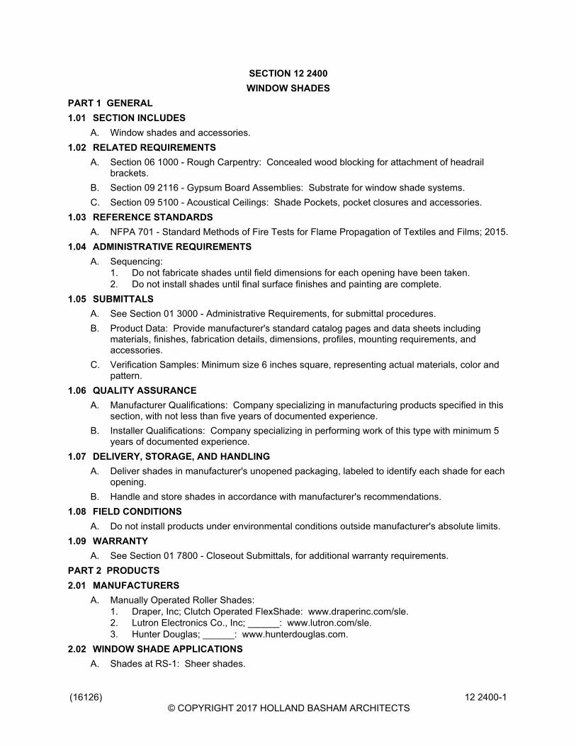
(16126)© COPYRIGHT 2017 HOLLAND BASHAM ARCHITECTS
12 2400-1
SECTION 12 2400WINDOW SHADES
PART 1 GENERAL1.01 SECTION INCLUDES
A. Window shades and accessories.1.02 RELATED REQUIREMENTS
A. Section 06 1000 - Rough Carpentry: Concealed wood blocking for attachment of headrailbrackets.
B. Section 09 2116 - Gypsum Board Assemblies: Substrate for window shade systems.C. Section 09 5100 - Acoustical Ceilings: Shade Pockets, pocket closures and accessories.
1.03 REFERENCE STANDARDSA. NFPA 701 - Standard Methods of Fire Tests for Flame Propagation of Textiles and Films; 2015.
1.04 ADMINISTRATIVE REQUIREMENTSA. Sequencing:
1. Do not fabricate shades until field dimensions for each opening have been taken.2. Do not install shades until final surface finishes and painting are complete.
1.05 SUBMITTALSA. See Section 01 3000 - Administrative Requirements, for submittal procedures.B. Product Data: Provide manufacturer's standard catalog pages and data sheets including
materials, finishes, fabrication details, dimensions, profiles, mounting requirements, andaccessories.
C. Verification Samples: Minimum size 6 inches square, representing actual materials, color andpattern.
1.06 QUALITY ASSURANCEA. Manufacturer Qualifications: Company specializing in manufacturing products specified in this
section, with not less than five years of documented experience.B. Installer Qualifications: Company specializing in performing work of this type with minimum 5
years of documented experience.1.07 DELIVERY, STORAGE, AND HANDLING
A. Deliver shades in manufacturer's unopened packaging, labeled to identify each shade for eachopening.
B. Handle and store shades in accordance with manufacturer's recommendations.1.08 FIELD CONDITIONS
A. Do not install products under environmental conditions outside manufacturer's absolute limits.1.09 WARRANTY
A. See Section 01 7800 - Closeout Submittals, for additional warranty requirements.PART 2 PRODUCTS2.01 MANUFACTURERS
A. Manually Operated Roller Shades:1. Draper, Inc; Clutch Operated FlexShade: www.draperinc.com/sle.2. Lutron Electronics Co., Inc; ______: www.lutron.com/sle.3. Hunter Douglas; ______: www.hunterdouglas.com.
2.02 WINDOW SHADE APPLICATIONSA. Shades at RS-1: Sheer shades.

(16126)© COPYRIGHT 2017 HOLLAND BASHAM ARCHITECTS
12 2400-2
1. Type: Roller shades.2. Mounting: Inside (between jambs).3. Operation: Manual and motorized, in locations indicated.
2.03 ROLLER SHADESA. Roller Shades: Fabric roller shades complete with mounting brackets, roller tubes, hembars,
hardware and accessories; fully factory-assembled.1. Drop: Regular roll.2. Size: As indicated on drawings.
B. Fabric: Non-flammable, color-fast, impervious to heat and moisture, and able to retain itsshape under normal operation; PVC-free; 100 percent recycled.1. Sheer Shades: Reduce glare yet still reveal considerable details to the outside; no
privacy; Openness Factor greater than 1 percent.2. Flammability: Pass NFPA 701 large and small tests.
C. Roller Tube: As required for type of operation, extruded aluminum with end caps.1. Fabric Attachment: Utilize extruded channel in tube to accept vinyl spline welded to fabric
edge.D. Hembars and Hembar Pockets: Wall thickness designed for weight requirements and
adaptation to uneven surfaces, to maintain bottom of shade straight and flat.E. Manual Operation: Clutch operated continuous loop; beaded ball chain.
2.04 ACCESSORIESA. Fascias: Size as required to conceal shade mounting.B. Brackets and Mounting Hardware: As recommended by manufacturer for mounting
configuration and span indicated.C. Fasteners: Non-corrosive, and as recommended by shade manufacturer.
2.05 FABRICATIONA. Fabricate shades to fit openings within specified tolerances.
1. Vertical Dimensions: Fill openings from head to sill with 1/2 inch space between bottombar and window stool.
PART 3 EXECUTION3.01 INSTALLATION
A. Install in accordance with manufacturer's instructions and approved shop drawings, usingmounting devices as indicated.
B. Installation Tolerances:1. Maximum Offset From Level: 1/16 inch.
C. Adjust level, projection and shade centering from mounting bracket. Verify there is notelescoping of shade fabric. Ensure smooth shade operation.
3.02 CLEANINGA. Clean soiled shades and exposed components as recommended by manufacturer.B. Replace shades that cannot be cleaned to "like new" condition.
3.03 PROTECTIONA. Protect installed products from subsequent construction operations.B. Touch-up, repair or replace damaged products before Substantial Completion.
3.04 MAINTENANCEA. See Section 01 7000 - Execution and Closeout Requirements, for additional requirements
relating to maintenance service.END OF SECTION

(16126)© COPYRIGHT 2017 HOLLAND BASHAM ARCHITECTS
12 2400-3

(16126)© COPYRIGHT 2017 HOLLAND BASHAM ARCHITECTS
12 2400-4

(16126)© COPYRIGHT 2017 HOLLAND BASHAM ARCHITECTS
12 3530-1
SECTION 12 3530RESIDENTIAL CASEWORK
PART 1 GENERAL1.01 SECTION INCLUDES
A. Kitchen cabinets.B. Vanity cabinets.C. Casework hardware.
1.02 RELATED REQUIREMENTSA. Section 12 3600 - Countertops.
1.03 REFERENCE STANDARDSA. BHMA A156.9 - American National Standard for Cabinet Hardware; 2010.B. KCMA A161.1 - Performance and Construction Standard for Kitchen and Vanity Cabinets;
2012.C. KCMA (DIR) - Directory of Certified Cabinet Manufacturers; current edition, online.
1.04 SUBMITTALSA. See Section 01 3000 - Administrative Requirements, for submittal procedures.B. Product Data: Provide component dimensions and construction details.C. Shop Drawings: Indicate casework locations, large scale plans, elevations, clearances
required, rough-in and anchor placement dimensions and tolerances, and ________.D. Samples: Submit two _________, ____x____ inch in size, illustrating each color of finish.
1.05 QUALITY ASSURANCEA. Products: Complying with KCMA A161.1 and KCMA Certified.B. Manufacturer: Company specializing in manufacturing the type of products specified in this
section, with minimum three years of documented experience.PART 2 PRODUCTS2.01 MANUFACTURERS
A. Residential Casework:1. Substitutions: See Section 01 6000 - Product Requirements.
2.02 COMPONENTSA. Cabinet Construction: Softwood lumber framing and particle board, tempered hardboard
gables.B. Countertops: As specified in Section 12 3600.C. Door and Drawer Fronts: Solid wood.D. Bolts, Nuts, Washers and Screws: Of size and type to suit application.E. Concealed Joint Fasteners: Threaded steel.
2.03 HARDWAREA. Hardware: Manufacturer's standard.B. Shelf Brackets: Manufacturer's Standard.C. Drawer and Door Pulls: Hafele #101.20.729 Stainless Steel, 3.78 inches wide or similar.D. Drawer Slides: Extension arms, steel construction.E. Hinges: 6 way adjustable, heavy-duty, self-closing, concealed.

(16126)© COPYRIGHT 2017 HOLLAND BASHAM ARCHITECTS
12 3530-2
2.04 FABRICATIONA. Shop assemble casework for delivery to site in units easily handled and to permit passage
through building openings.B. Fabricate corners and joints without gaps or inaccessible spaces or areas where dirt or
moisture could accumulate.2.05 FINISHES
A. Wood species: MapleB. Finish: See Color Schedue 09 0600
PART 3 EXECUTION3.01 INSTALLATION
A. Install casework, components and accessories in accordance with manufacturer's instructions.B. Use anchoring devices to suit conditions and substrate materials encountered.C. Set casework items plumb and square, securely anchored to building structure.
3.02 ADJUSTINGA. Adjust doors, drawers, hardware, fixtures, and other moving or operating parts to function
smoothly.3.03 CLEANING
A. Clean casework, countertops, shelves, and hardware.3.04 PROTECTION
A. Do not permit finished casework to be exposed to continued construction activity.END OF SECTION

(16126)© COPYRIGHT 2017 HOLLAND BASHAM ARCHITECTS
12 3600-1
SECTION 12 3600COUNTERTOPS
PART 1 GENERAL1.01 SECTION INCLUDES
A. Countertops for architectural cabinet work.B. Countertops for manufactured casework.C. Sinks molded into countertops.
1.02 RELATED REQUIREMENTSA. Section 06 4100 - Architectural Wood Casework.B. Section 12 3530 - Residential Casework.C. Section 22 4000 - Plumbing Fixtures: Sinks.
1.03 PRICE AND PAYMENT PROCEDURESA. See Section 01 2300 - Alternates, for product alternates affecting this section.
1.04 REFERENCE STANDARDSA. AWI (QCP) - Quality Certification Program; current edition at www.awiqcp.org.B. AWI/AWMAC/WI (AWS) - Architectural Woodwork Standards; 2014.C. AWMAC/WI (NAAWS) - North American Architectural Woodwork Standards, U.S. Version 3.0;
2016.D. ISFA 2-01 - Classification and Standards for Solid Surfacing Material; 2013.E. NEMA LD 3 - High-Pressure Decorative Laminates; 2005.F. PS 1 - Structural Plywood; 2009.
1.05 SUBMITTALSA. See Section 01 3000 - Administrative Requirements, for submittal procedures.B. Product Data: Manufacturer's data sheets on each product to be used, including:
1. Preparation instructions and recommendations.2. Storage and handling requirements and recommendations.3. Specimen warranty.
C. Shop Drawings: Complete details of materials and installation; combine with shop drawings ofcabinets and casework specified in other sections.
D. Verification Samples: For each finish product specified, minimum size 6 inches square,representing actual product, color, and patterns.
E. Test Reports: Chemical resistance testing, showing compliance with specified requirements.F. Maintenance Data: Manufacturer's instructions and recommendations for maintenance and
repair of countertop surfaces.1.06 QUALITY ASSURANCE
A. Installer Qualifications: Company specializing in performing work of the type specified in thissection, with not less than three years of documented experience.
B. Quality Certification: Comply with AWI (QCP) woodwork association quality certificationservice/program in accordance with requirements for work specified in this section.1. Provide labels or certificates indicating that the installed work complies with
AWI/AWMAC/WI (AWS) or AWMAC/WI (NAAWS) requirements for grade or gradesspecified.
2. Provide designated labels on shop drawings as required by certification program.3. Provide designated labels on installed products as required by certification program.

(16126)© COPYRIGHT 2017 HOLLAND BASHAM ARCHITECTS
12 3600-2
4. Submit certifications upon completion of installation that verifies this work is in compliancewith specified requirements.
1.07 DELIVERY, STORAGE, AND HANDLINGA. Store products in manufacturer's unopened packaging until ready for installation.B. Store and dispose of solvent-based materials, and materials used with solvent-based materials,
in accordance with requirements of local authorities having jurisdiction.1.08 FIELD CONDITIONS
A. Maintain environmental conditions (temperature, humidity, and ventilation) within limitsrecommended by manufacturer for optimum results. Do not install products underenvironmental conditions outside manufacturer's absolute limits.
PART 2 PRODUCTS2.01 COUNTERTOPS
A. Quality Standard: See Section 06 4100.B. Plastic Laminate Countertops: High-pressure decorative laminate (HPDL) sheet bonded to
substrate.1. Laminate Sheet, Type ___: NEMA LD 3, Grade HGS, ____ inch nominal thickness.
a. Manufacturers:1) Formica Corporation; _______: www.formica.com.2) Panolam Industries International, IncPionite; _____: www.pionitelaminates.com.3) Wilsonart; _____: www.wilsonart.com.
b. Finish: Matte or suede, gloss rating of 5 to 20.2. Exposed Edge Treatment: Square, substrate built up to minimum 1-1/4 inch thick;
covered with matching laminate.3. Back and End Splashes: Same material, same construction.4. Fabricate in accordance with AWI/AWMAC/WI (AWS) or AWMAC/WI (NAAWS), Section
11 - Countertops, Custom Grade.C. Solid Surfacing Countertops: Solid surfacing sheet or plastic resin casting over continuous
substrate.1. Flat Sheet Thickness: 1/4 inch, minimum.2. Solid Surfacing Sheet and Plastic Resin Castings: Complying with ISFA 2-01 and NEMA
LD 3; acrylic or polyester resin, mineral filler, and pigments; homogenous, non-porous andcapable of being worked and repaired using standard woodworking tools; no surfacecoating; color and pattern consistent throughout thickness.a. Finish on Exposed Surfaces: Matte, gloss rating of 5 to 20.
3. Other Components Thickness: 1/2 inch, minimum.4. Back and End Splashes: Same sheet material, square top; minimum 4 inches high.
D. Natural Stone Countertops: Stone slabs bonded to substrate; use as large pieces as possiblewith inconspicuous adhesive joints.1. Stone: Granite without cracks, voids, or pin holes; filling with matching epoxy resin is
acceptable.2. Color: ______.3. Quarry Name: ________; no substitutions.4. Stone Thickness: 1/2 inch, minimum.5. Surface Finish: Honed, non-glare.6. Back and End Splashes (Base Bid): Same material, same thickness; for field attachment.
2.02 MATERIALSA. Plywood for Supporting Substrate: PS 1 Exterior Grade, A-C veneer grade, minimum 5-ply;
minimum 3/4 inch thick; join lengths using metal splines.B. Adhesives: Chemical resistant waterproof adhesive as recommended by manufacturer of
materials being joined.

(16126)© COPYRIGHT 2017 HOLLAND BASHAM ARCHITECTS
12 3600-3
C. Joint Sealant: Mildew-resistant silicone sealant, clear.2.03 FABRICATION
A. Fabricate tops and splashes in the largest sections practicable, with top surface of joints flush.1. Join lengths of tops using best method recommended by manufacturer.2. Fabricate to overhang fronts and ends of cabinets 1 inch except where top butts against
cabinet or wall.3. Prepare all cutouts accurately to size; replace tops having improperly dimensioned or
unnecessary cutouts or fixture holes.B. Provide back/end splash wherever counter edge abuts vertical surface unless otherwise
indicated (Base Bid).1. Secure to countertop with concealed fasteners and with contact surfaces set in waterproof
glue.2. Height: 4 inches, unless otherwise indicated.
C. Solid Surfacing: Fabricate tops up to 144 inches long in one piece; join pieces with adhesivesealant in accordance with manufacturer's recommendations and instructions.
PART 3 EXECUTION3.01 EXAMINATION
A. Do not begin installation until substrates have been properly prepared.B. If substrate preparation is the responsibility of another installer, notify Architect of unsatisfactory
preparation before proceeding.C. Verify that wall surfaces have been finished and mechanical and electrical services and outlets
are installed in proper locations.3.02 PREPARATION
A. Clean surfaces thoroughly prior to installation.B. Prepare surfaces using the methods recommended by the manufacturer for achieving the best
result for the substrate under the project conditions.3.03 INSTALLATION
A. Securely attach countertops to cabinets using concealed fasteners. Make flat surfaces level;shim where required.
B. Attach plastic laminate countertops using screws with minimum penetration into substrateboard of 5/8 inch.
C. Seal joint between back/end splashes and vertical surfaces.3.04 TOLERANCES
A. Variation From Horizontal: 1/8 inch in 10 feet, maximum.B. Offset From Wall, Countertops: 1/8 inch maximum; 1/16 inch minimum.C. Field Joints: 1/8 inch wide, maximum.
3.05 CLEANINGA. Clean countertops surfaces thoroughly.
3.06 PROTECTIONA. Protect installed products until completion of project.B. Touch-up, repair or replace damaged products before Date of Substantial Completion.
END OF SECTION

(16126)© COPYRIGHT 2017 HOLLAND BASHAM ARCHITECTS
12 3600-4

HOLLAND BASHAM ARCHITECTS 1 1 9 S O U T H 4 9 A V E N U E O M A H A , N E B R A S K A 6 8 1 3 2 4 0 2 - 5 5 1 - 0 8 0 0 F A X : 4 0 2 - 5 5 1 - 2 2 9 5 E M A I L : H B A @ H B A 1 . C O M
DIVISION 14
CONVEYING EQUIPMENT
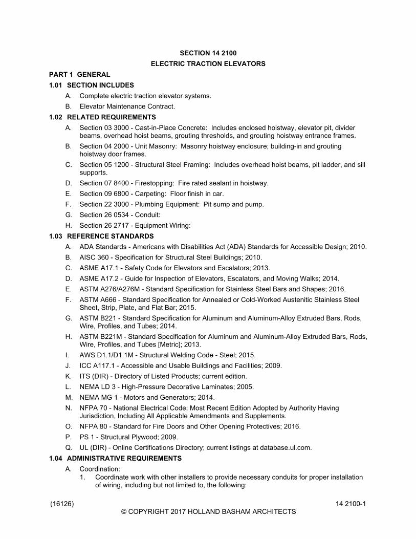
(16126)© COPYRIGHT 2017 HOLLAND BASHAM ARCHITECTS
14 2100-1
SECTION 14 2100ELECTRIC TRACTION ELEVATORS
PART 1 GENERAL1.01 SECTION INCLUDES
A. Complete electric traction elevator systems.B. Elevator Maintenance Contract.
1.02 RELATED REQUIREMENTSA. Section 03 3000 - Cast-in-Place Concrete: Includes enclosed hoistway, elevator pit, divider
beams, overhead hoist beams, grouting thresholds, and grouting hoistway entrance frames.B. Section 04 2000 - Unit Masonry: Masonry hoistway enclosure; building-in and grouting
hoistway door frames.C. Section 05 1200 - Structural Steel Framing: Includes overhead hoist beams, pit ladder, and sill
supports.D. Section 07 8400 - Firestopping: Fire rated sealant in hoistway.E. Section 09 6800 - Carpeting: Floor finish in car.F. Section 22 3000 - Plumbing Equipment: Pit sump and pump.G. Section 26 0534 - Conduit:H. Section 26 2717 - Equipment Wiring:
1.03 REFERENCE STANDARDSA. ADA Standards - Americans with Disabilities Act (ADA) Standards for Accessible Design; 2010.B. AISC 360 - Specification for Structural Steel Buildings; 2010.C. ASME A17.1 - Safety Code for Elevators and Escalators; 2013.D. ASME A17.2 - Guide for Inspection of Elevators, Escalators, and Moving Walks; 2014.E. ASTM A276/A276M - Standard Specification for Stainless Steel Bars and Shapes; 2016.F. ASTM A666 - Standard Specification for Annealed or Cold-Worked Austenitic Stainless Steel
Sheet, Strip, Plate, and Flat Bar; 2015.G. ASTM B221 - Standard Specification for Aluminum and Aluminum-Alloy Extruded Bars, Rods,
Wire, Profiles, and Tubes; 2014.H. ASTM B221M - Standard Specification for Aluminum and Aluminum-Alloy Extruded Bars, Rods,
Wire, Profiles, and Tubes [Metric]; 2013.I. AWS D1.1/D1.1M - Structural Welding Code - Steel; 2015.J. ICC A117.1 - Accessible and Usable Buildings and Facilities; 2009.K. ITS (DIR) - Directory of Listed Products; current edition.L. NEMA LD 3 - High-Pressure Decorative Laminates; 2005.M. NEMA MG 1 - Motors and Generators; 2014.N. NFPA 70 - National Electrical Code; Most Recent Edition Adopted by Authority Having
Jurisdiction, Including All Applicable Amendments and Supplements.O. NFPA 80 - Standard for Fire Doors and Other Opening Protectives; 2016.P. PS 1 - Structural Plywood; 2009.Q. UL (DIR) - Online Certifications Directory; current listings at database.ul.com.
1.04 ADMINISTRATIVE REQUIREMENTSA. Coordination:
1. Coordinate work with other installers to provide necessary conduits for proper installationof wiring, including but not limited to, the following:
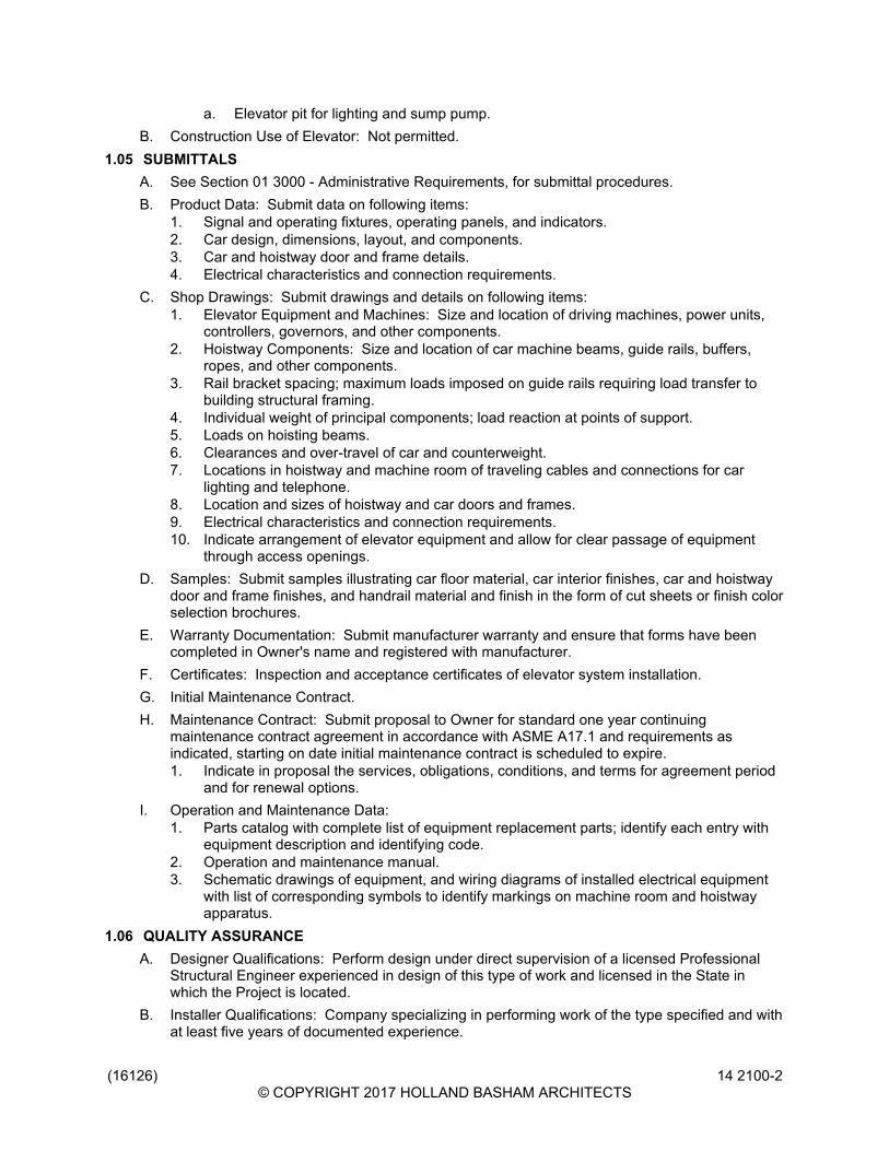
(16126)© COPYRIGHT 2017 HOLLAND BASHAM ARCHITECTS
14 2100-2
a. Elevator pit for lighting and sump pump.B. Construction Use of Elevator: Not permitted.
1.05 SUBMITTALSA. See Section 01 3000 - Administrative Requirements, for submittal procedures.B. Product Data: Submit data on following items:
1. Signal and operating fixtures, operating panels, and indicators.2. Car design, dimensions, layout, and components.3. Car and hoistway door and frame details.4. Electrical characteristics and connection requirements.
C. Shop Drawings: Submit drawings and details on following items:1. Elevator Equipment and Machines: Size and location of driving machines, power units,
controllers, governors, and other components.2. Hoistway Components: Size and location of car machine beams, guide rails, buffers,
ropes, and other components.3. Rail bracket spacing; maximum loads imposed on guide rails requiring load transfer to
building structural framing.4. Individual weight of principal components; load reaction at points of support.5. Loads on hoisting beams.6. Clearances and over-travel of car and counterweight.7. Locations in hoistway and machine room of traveling cables and connections for car
lighting and telephone.8. Location and sizes of hoistway and car doors and frames.9. Electrical characteristics and connection requirements.10. Indicate arrangement of elevator equipment and allow for clear passage of equipment
through access openings.D. Samples: Submit samples illustrating car floor material, car interior finishes, car and hoistway
door and frame finishes, and handrail material and finish in the form of cut sheets or finish colorselection brochures.
E. Warranty Documentation: Submit manufacturer warranty and ensure that forms have beencompleted in Owner's name and registered with manufacturer.
F. Certificates: Inspection and acceptance certificates of elevator system installation.G. Initial Maintenance Contract.H. Maintenance Contract: Submit proposal to Owner for standard one year continuing
maintenance contract agreement in accordance with ASME A17.1 and requirements asindicated, starting on date initial maintenance contract is scheduled to expire.1. Indicate in proposal the services, obligations, conditions, and terms for agreement period
and for renewal options.I. Operation and Maintenance Data:
1. Parts catalog with complete list of equipment replacement parts; identify each entry withequipment description and identifying code.
2. Operation and maintenance manual.3. Schematic drawings of equipment, and wiring diagrams of installed electrical equipment
with list of corresponding symbols to identify markings on machine room and hoistwayapparatus.
1.06 QUALITY ASSURANCEA. Designer Qualifications: Perform design under direct supervision of a licensed Professional
Structural Engineer experienced in design of this type of work and licensed in the State inwhich the Project is located.
B. Installer Qualifications: Company specializing in performing work of the type specified and withat least five years of documented experience.

(16126)© COPYRIGHT 2017 HOLLAND BASHAM ARCHITECTS
14 2100-3
C. Testing Agency Qualifications: Independent firm specializing in performing testing andinspections of the type specified in this section.
D. Products Requiring Fire Resistance Rating: Listed and classified by ITS (DIR), UL (DIR), ortesting agency acceptable to authorities having jurisdiction.
E. Products Requiring Electrical Connection: Listed and classified by UL (DIR) or testing agencyacceptable to authorities having jurisdiction as suitable for the purpose indicated in constructiondocuments.
1.07 WARRANTYA. See Section 01 7800 - Closeout Submittals, for additional warranty requirements.B. Provide manufacturer's warranty for elevator operating equipment and devices for one year
from Date of Substantial Completion.PART 2 PRODUCTS2.01 MANUFACTURERS
A. Basis of Design - Electric Traction Elevators: KONE; Ecospace.B. Other Acceptable Manufacturers - Electric Traction Elevators:
1. KONE, Inc.; Ecospace: www.us.kone.com.2. ThyssenKrupp Elevator; Synergy Self Support: www.thyssenkruppelevator.com.
C. Substitutions: See Section 01 6000 - Product Requirements.1. For any product not identified as Basis of Design, submit information as specified for
substitutions.D. Products other than Basis of Design are subject to compliance with specified requirements and
prior approval of Architect. By using products other than Basis of Design, the Contractoraccepts responsibility for costs associated with any necessary modifications to related work,including any design fees.
E. Source Limitations: Provide elevator and associated equipment and components produced bythe same manufacturer as the other elevator equipment used for this project and obtained froma single supplier .
2.02 ELECTRIC TRACTION ELEVATORSA. Electric Traction Elevator:
1. Electric Traction Elevator Equipment:a. Gearless Traction Machine: Single wrapped traction driving sheave, with single
brake.2. Drive System:3. Operation Control Type:4. Interior Car Height: 108 inch.5. Electrical Power: 480 volts; alternating current (AC); three phase; 60 Hz.6. Rated Net Capacity: 3500 pounds.7. Rated Speed: 150 feet per minute.8. Hoistway Size: As indicated on drawings.9. Interior Car Platform Size: 80 inch wide by 65 inch deep.10. Elevator Pit Depth: 60 inch.11. Overhead Clearance at Top Floor: As indicated on drawings.12. Travel Distance: As indicated on drawings.13. Number of Stops: 6.14. Number of Openings: 6 Front.15. Traction Machine Location: As indicated on drawings.
2.03 COMPONENTSA. Elevator Equipment:

(16126)© COPYRIGHT 2017 HOLLAND BASHAM ARCHITECTS
14 2100-4
1. Motors, Controllers, Controls, Buttons, Wiring, Devices, and Indicators: Comply withNFPA 70. Refer to Section 26 2717.
2. Guide Rails, Cables, Counterweights, Sheaves, Buffers, Attachment Brackets andAnchors: Design criteria for components includes safety factors in accordance withapplicable requirements of Elevator Code, ASME A17.1.
3. Buffers:4. Lubrication Equipment:
a. Provide grease fittings for periodic lubrication of bearings.b. Grease Cups: Automatic feed type.c. Lubrication Points: Visible and easily accessible.
B. Electrical Equipment:1. Motors: NEMA MG 1.2. Boxes, Conduit, Wiring, and Devices: As required by NFPA 70. Refer to Sections 26
0534 and 26 2717.3. Spare Conductors: Provide ten percent in extra conductors and two pairs of shielded
audio cables in traveling cables.4. Include wiring and connections to elevator devices remote from hoistway and between
elevator machine room. Provide additional components and wiring to suit machine roomlayout. Refer to Section 26 2717.
2.04 PERFORMANCE REQUIREMENTSA. Regulatory Requirements: Comply with ASME A17.1, applicable local codes, and authorities
having jurisdiction (AHJ).B. Accessibility Requirements: Comply with ADA Standards and ICC A117.1.C. Perform structural steel design, fabrication, and installation in accordance with AISC 360.D. Perform welding of steel in accordance with AWS D1.1/D1.1M.E. Fabricate and install door and frame assemblies in accordance with NFPA 80 and in
compliance with requirements of authorities having jurisdiction.F. Perform electrical work in accordance with NFPA 70.
2.05 OPERATION CONTROLSA. Elevator Controls: Provide landing operating panels, landing indicator panels, and hall
lanterns.1. Landing Operating Panels: Metallic type, one for originating "Up" and one for originating
"Down" calls, one button only at terminating landings; with illuminating indicators.2. Landing Indicator Panels: Illuminating.3. Comply with ADA Standards for elevator controls.
B. Interconnect elevator control system with building security, fire alarm, smoke alarm, andbuilding management control systems.
C. Door Operation Controls:1. Program door control to open doors automatically when car arrives at floor landing.2. Render "Door Close" button inoperative when car is standing at dispatch landing with
doors open.3. Door Safety Devices: Moveable, retractable safety edges, quiet in operation; equipped
with photo-electric light rays.D. Provide "Firefighter's Emergency Operation" in accordance with ASME A17.1, applicable
building codes, and authorities having jurisdiction (AHJ).1. Designated Landing: Main Lobby.2. Provide a lock box with a break-glass for the Elevator Hall Door Emergency key and also
the Firefighter Service keys. Locate these keys near the elevator(s) at the Designatedfloor for Firefighter access where directed by the Authority having Jurisdiction.

(16126)© COPYRIGHT 2017 HOLLAND BASHAM ARCHITECTS
14 2100-5
2.06 OPERATION CONTROL TYPEA. Two-Car Selective Collective Automatic (Duplex Collective Automatic) Operation Control:
Applies to cars in two elevator shafts.1. Park one car at main floor and designate other as free car, at landing last served or at a
predetermined upper floor landing.2. Arrange free car to answer landing calls either above or below landing where car is
standing except main floor and basement landing calls.3. When free car is answering calls, automatically start an alternate car to answer landing
calls under any of the following conditions:a. Registration of up calls from landings below the free car while it is traveling up by
alternate car below.b. Registration of up or down calls from landings above the free car while it is traveling
down by alternate car.c. Free car fails to clear registered landing calls within 40 seconds, or to move alternate
car in response to registered landing calls within this time frame.4. Register and answer calls by momentary pressure on one or more car buttons; cause car
to respond.5. Once started, either in response to car button calls, or to landing button calls, respond to
calls registered for the direction of the traveling car in the order that landings are reached,regardless of sequence that calls were registered.
6. Allow only one car to stop in response to any one landing call.7. Return first free car to main floor after answering landing calls.8. Should both cars finish their calls at main floor, designate one car as the free car.9. If no car buttons are pressed and car starts up in response to several landing down calls,
proceed first to the highest landing down call, then reverse to collect other landing downcalls. Collect up calls similarly when car starts down in response to such calls.
10. If a car stops for a landing call, and car button matching direction the car was traveling ispressed within a predetermined time interval after a landing stop, proceed in the samedirection regardless of other landing calls that are registered.
11. If down landing buttons are pressed while car is traveling up, do not stop at those landingsbut allow those calls to remain registered for answering by the next down traveling car.
12. After the highest car has responded to up landing calls, reverse car automatically andrespond to down landing calls.
13. When traveling down, a car will not respond to up calls. Allow those up calls to remainregistered to be answered by next available car on an up trip.
14. Include a time delay to hold car for an adjustable time interval at landings where stops aremade to enable passengers to enter or leave the car. Cancel the time interval uponregistration of a car call or pressure on the car door close button.
15. Permit a registered car call to establish the direction of travel when a car has answeredthe farthest car call, even if other landing calls are registered.
16. Answer calls to the basement landing with the car that is normally parked at the main floorunless the free car is at the basement.
17. If a car is removed from service, the other car shall answer landing calls.2.07 SERVICE CONTROL TYPE
A. Independent Service Control:1. Provide key operated "Independent Service" on car operating panel. Key activation will
remove that car from normal operation and cancel pre-registered car calls.2. Car will respond to selected floor. Car will not respond to any calls from landing call
buttons. Car will only respond to calls placed on the car operating panel. Doors willremain open at last landing requested. Doors will close with a constant pressure on "DoorClose" button.
3. Key activation to normal operation will return car to normal operation.

(16126)© COPYRIGHT 2017 HOLLAND BASHAM ARCHITECTS
14 2100-6
2.08 EMERGENCY POWERA. Set-up elevator operation to run with building emergency power supply when the normal
building power supply fails, and in compliance with ASME A17.1 requirements.B. Building Emergency Power Supply: Supplied by backup generator; provide elevator system
components as required for emergency power characteristics with phase rotation the same asfor normal power.1. Provide transfer switches and auxiliary contacts.2. Install connections to power feeders.
C. Emergency Lighting: Comply with ASME A17.1 elevator lighting requirements.D. Provide operational control circuitry for adapting the change from normal to emergency power.E. Upon transfer to emergency power, advance one elevator at a time to a pre-selected landing,
stop car, open doors, disable operating circuits, and hold in standby condition.2.09 MATERIALS
A. Stainless Steel Sheet: ASTM A666, Type 304; No. 4 Brushed finish unless otherwiseindicated.
B. Stainless Steel Bars, Shapes and Moldings: ASTM A276/A276M, Type 304.C. Extruded Aluminum: ASTM B221 (ASTM B221M), natural anodized finish unless otherwise
indicated.D. Plywood: PS 1, Structural I, Grade C-D or better, sanded.E. Carpet Flooring: As specified in Section 09 6800.F. Plastic Laminate: NEMA LD 3, Type HGS, color as selected by Architect from manufacturer's
standard line of colors.2.10 CAR AND HOISTWAY ENTRANCES
A. Elevator, _____:1. Car and Hoistway Entrances, Main Elevator Lobby:
a. Hoistway Fire Rating: As indicated on drawings.b. Elevator Door Fire Rating: 2 Hours.c. Framed Opening Finish and Material: Brushed stainless steel.d. Car Door Material: Stainless steel, with rigid sandwich panel construction.e. Hoistway Door Material: Stainless steel, with rigid sandwich panel construction.f. Door Type: Single leaf.g. Door Operation: Side opening, two speed.h. Door Width: ___ inch.i. Door Height: 84 inch.j. Sills: Extruded aluminum.
B. Sills/Thresholds: Configure to align with frame return and coordinate with floor finish.2.11 CAR EQUIPMENT AND MATERIALS
A. Elevator Car:1. Car Operating Panel: Provide main and auxiliary; flush-mounted applied face plate, with
illuminated call buttons corresponding to floors served with "Door Open/Door Close"buttons, "Door Open" button, "Door Close" button, and alarm button.a. Panel Material: Integral with front return; one per car.b. Car Floor Position Indicator: Above car operating panel with illuminating position
indicators.c. Locate alarm button where it is unlikely to be accidentally actuated; not more than 54
inch above car finished floor.d. Provide matching service cabinet integral with front return panel, with hinged door in
each car.

(16126)© COPYRIGHT 2017 HOLLAND BASHAM ARCHITECTS
14 2100-7
e. Provide following within service cabinet as part of car operating panel:1) Telephone cabinet and hard-wired connection with telephone.
2. Flooring: Carpeting.3. Front Return Panel: Match material of car door.4. Door Wall: Match material of car door.5. Side Walls: Plastic laminate on plywood.6. Rear Wall: Plastic laminate on plywood.7. Hand Rail: Stainless steel, at rear wall. Provide open clearance space 1-1/2 inch (38 mm)
wide to face of wall.a. Stainless Steel Finish: No. 4 Brushed.
8. Ceiling: a. Lighting: As selected from manufacturer's standard line.
9. Provide emergency access panel for egress from car at ceiling.B. Car Accessories:
1. Protective Pads: Canvas cover, padded with manufacturer's standard fill material, sewnwith piping edges; fire resistant in compliance with ASME A17.1; brass grommets forsupports, covering side and rear walls and front return, with cut-out for control panel;provide one set for each elevator.a. Color: As selected by Architect.b. Provide at least 4 inch clearance from bottom of pad to finished floor.c. Pad Supports: Stainless steel studs, and mounted from top of wall panels.
2.12 FINISHESPART 3 EXECUTION3.01 EXAMINATION
A. Verify existing conditions before starting this work.B. Verify that hoistway, pit, and machine room are ready for work of this section.C. Verify hoistway shaft and openings are of correct size and within tolerance.D. Verify location and size of machine foundation and position of machine foundation bolts.E. Verify that electrical power is available and of correct characteristics.
3.02 PREPARATIONA. Arrange for temporary electrical power for installation work and testing of elevator components.
Comply with requirements of Section 01 5000 - Temporary Facilities and Controls.B. Maintain elevator pit excavation free of water.
3.03 INSTALLATIONA. Coordinate this work with installation of hoistway wall construction.B. Install system components, and connect equipment to building utilities.C. Provide conduit, electrical boxes, wiring, and accessories. Refer to Sections 26 0534 and 26
2717.D. Mount machines and motors on vibration and acoustic isolators.
1. Place on structural supports and bearing plates.2. Securely fasten to building supports.3. Prevent lateral displacement.
E. Install hoistway, elevator equipment, and components in accordance with approved shopdrawings.
F. Install guide rails to allow for expansion and contraction movement of guide rails.G. Accurately machine and align guide rails, forming smooth joints with machined splice plates.

(16126)© COPYRIGHT 2017 HOLLAND BASHAM ARCHITECTS
14 2100-8
H. Install hoistway door sills, frames, and headers in hoistway walls; grout sills in place, sethoistway floor entrances in alignment with car openings, and align plumb with hoistway.
I. Structural Metal Surfaces: Clean surfaces of rust, oil or grease; wipe clean with solvent; primewith two coats.
J. Wood Surfaces not Exposed to Public View: Finish with one coat primer; one coat enamel.K. Adjust equipment for smooth and quiet operation.
3.04 TOLERANCESA. Guide Rail Alignment: Plumb and parallel to each other in accordance with ASME A17.1 and
ASME A17.2.B. Car Movement on Aligned Guide Rails: Smooth movement, without any objectionable lateral or
oscillating movement or vibration.3.05 FIELD QUALITY CONTROL
A. See Section 01 4000 - Quality Requirements, for additional requirements.B. Testing and inspection by regulatory agencies certified in accordance with ASME QEI 1 will be
performed at their discretion.1. Schedule tests with agencies and notify Owner and Architect.2. Obtain permits as required to perform tests.3. Document regulatory agency tests and inspections in accordance with requirements.4. Perform tests required by regulatory agencies.5. Furnish test and approval certificates issued by authorities having jurisdiction.
3.06 ADJUSTINGA. Adjust for smooth acceleration and deceleration of car to minimize passenger discomfort.B. Adjust with automatic floor leveling feature at each floor landing to reach 1/4 inch maximum
from flush with sill.3.07 CLEANING
A. Remove protective coverings from finished surfaces.B. Clean surfaces and components in accordance with manufacturers written instructions.
3.08 CLOSEOUT ACTIVITIESA. See Section 01 7800 - Closeout Submittals, for closeout submittals.B. Demonstrate proper operation of equipment to Owner's designated representative.
3.09 PROTECTIONA. Do not permit construction traffic within car after cleaning.B. Protect installed products until Date of Substantial Completion.C. Touch-up, repair, or replace damaged products and materials before Date of Substantial
Completion.3.10 MAINTENANCE
A. Provide Initial Maintenance Contract of elevator system and components in accordance withASME A17.1 and requirements as indicated for 3 months from Date of Substantial Completion.
B. Perform maintenance contract services using competent and qualified personnel under thesupervision and direct employ of the elevator manufacturer or installer.
C. Maintenance contract services shall not be assigned or transferred to any agent or other entitywithout prior written consent of Owner.
D. Examine system components bi-monthly.E. Include systematic examination, adjustment, and lubrication of elevator equipment.F. Replace wire ropes when necessary to maintain the required factor of safety.

(16126)© COPYRIGHT 2017 HOLLAND BASHAM ARCHITECTS
14 2100-9
G. Perform work without removing cars from use during peak traffic periods.H. Provide emergency call back service at all hours throughout period of this maintenance
contract.END OF SECTION

(16126)© COPYRIGHT 2017 HOLLAND BASHAM ARCHITECTS
14 2100-10

HOLLAND BASHAM ARCHITECTS 1 1 9 S O U T H 4 9 A V E N U E O M A H A , N E B R A S K A 6 8 1 3 2 4 0 2 - 5 5 1 - 0 8 0 0 F A X : 4 0 2 - 5 5 1 - 2 2 9 5 E M A I L : H B A @ H B A 1 . C O M
DIVISION 21
FIRE SUPRESSION

THE CENTERLINE APARTMENTS 16126
OMAHA, NE
GENERAL REQUIREMENTS FOR FIRE SUPPRESSION 210100 - 1
SECTION 210100 - GENERAL REQUIREMENTS FOR FIRE SUPPRESSION
PART 1 - GENERAL
1.1 RELATED DOCUMENTS
A. Drawings and general provisions of the Contract, including General and Supplementary
Conditions apply to this Section.
B. Division 21, 22 and 23 Conditions apply to this Section.
1.2 SUMMARY
A. This Section includes general mechanical requirements and shall apply to all phases of the work
specified, indicated on the drawings or required to provide for complete installation of fire
suppression systems.
B. Refer to Section 230100 for General Requirements for Mechanical
C. Refer to Section 230500 for Basic Mechanical Materials and Methods
D. Refer to Section 230505 for Basic Piping Materials and Methods
PART 2 - PRODUCTS (Not Applicable)
PART 3 - EXECUTION (Not Applicable)
END OF SECTION 210100

THE CENTERLINE APARTMENTS 16126
OMAHA, NE
WATER-BASED FIRE-SUPPRESSION SYSTEMS 211000 - 1
SECTION 211000 - WATER-BASED FIRE-SUPPRESSION SYSTEMS
PART 1 - GENERAL
1.1 RELATED DOCUMENTS
A. Drawings and general provisions of the Contract, including General and Supplementary
Conditions and Division 01 Specification Sections, apply to this Section.
1.2 SUMMARY
A. This Section includes the following fire-suppression piping inside the building:
1. Manual wet-type, Class I standpipe systems.
2. Wet-pipe sprinkler systems.
B. The project shall be provided with a manual wet-type, Class 1 standpipe system in each
stairway.
C. The project shall be protected throughout by a wet pipe fire sprinkler system. Apartment areas
shall be protected by a system in accordance with NFPA 13R. Garage areas shall be protected
by a system in accordance with NFPA 13.
D. The attic shall be provided with draft stops and will not require fire sprinkler protection.
E. All exterior patios and balconies shall be protected by fire sprinklers per NFPA 13R.
1.3 SYSTEM DESCRIPTIONS
A. Combined Standpipe and Sprinkler System: Fire-suppression system with both standpipe and
sprinkler systems. Sprinkler system is supplied from standpipe system.
B. Manual Wet-Type, Class I Standpipe System: Includes NPS 2-1/2 hose connections. Has small
water supply to maintain water in standpipes. Piping is wet, but water must be pumped into
standpipes to satisfy demand.
C. Wet-Pipe Sprinkler System: Automatic sprinklers are attached to piping containing water and
that is connected to water supply. Water discharges immediately from sprinklers when they are
opened. Sprinklers open when heat melts fusible link or destroys frangible device. Hose
connections are included if indicated.
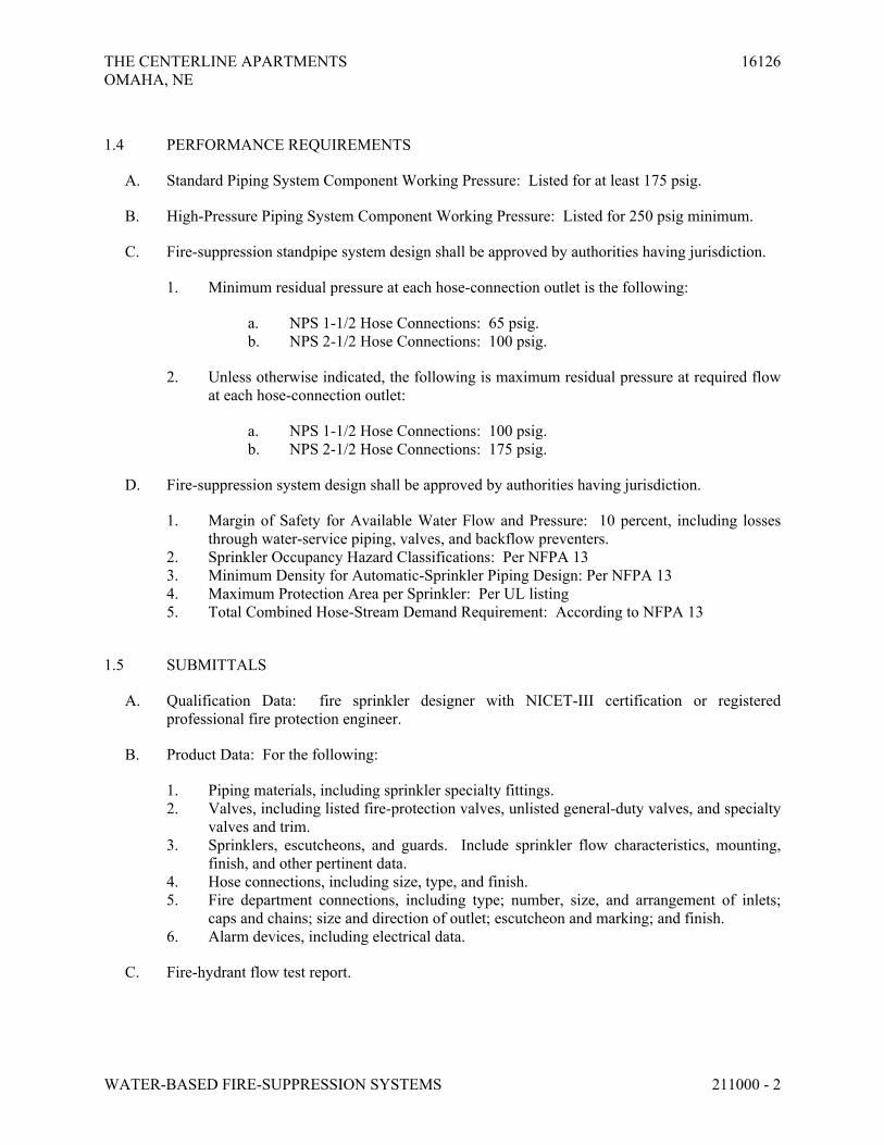
THE CENTERLINE APARTMENTS 16126
OMAHA, NE
WATER-BASED FIRE-SUPPRESSION SYSTEMS 211000 - 2
1.4 PERFORMANCE REQUIREMENTS
A. Standard Piping System Component Working Pressure: Listed for at least 175 psig.
B. High-Pressure Piping System Component Working Pressure: Listed for 250 psig minimum.
C. Fire-suppression standpipe system design shall be approved by authorities having jurisdiction.
1. Minimum residual pressure at each hose-connection outlet is the following:
a. NPS 1-1/2 Hose Connections: 65 psig.
b. NPS 2-1/2 Hose Connections: 100 psig.
2. Unless otherwise indicated, the following is maximum residual pressure at required flow
at each hose-connection outlet:
a. NPS 1-1/2 Hose Connections: 100 psig.
b. NPS 2-1/2 Hose Connections: 175 psig.
D. Fire-suppression system design shall be approved by authorities having jurisdiction.
1. Margin of Safety for Available Water Flow and Pressure: 10 percent, including losses
through water-service piping, valves, and backflow preventers.
2. Sprinkler Occupancy Hazard Classifications: Per NFPA 13
3. Minimum Density for Automatic-Sprinkler Piping Design: Per NFPA 13
4. Maximum Protection Area per Sprinkler: Per UL listing
5. Total Combined Hose-Stream Demand Requirement: According to NFPA 13
1.5 SUBMITTALS
A. Qualification Data: fire sprinkler designer with NICET-III certification or registered
professional fire protection engineer.
B. Product Data: For the following:
1. Piping materials, including sprinkler specialty fittings.
2. Valves, including listed fire-protection valves, unlisted general-duty valves, and specialty
valves and trim.
3. Sprinklers, escutcheons, and guards. Include sprinkler flow characteristics, mounting,
finish, and other pertinent data.
4. Hose connections, including size, type, and finish.
5. Fire department connections, including type; number, size, and arrangement of inlets;
caps and chains; size and direction of outlet; escutcheon and marking; and finish.
6. Alarm devices, including electrical data.
C. Fire-hydrant flow test report.

THE CENTERLINE APARTMENTS 16126
OMAHA, NE
WATER-BASED FIRE-SUPPRESSION SYSTEMS 211000 - 3
D. Preliminary Sprinkler Piping Drawings: Working plans, prepared according to NFPA 13,
submitted to architect/Engineer for preliminary review prior to submitting to authorities having
jurisdiction.
E. Approved Sprinkler Piping Drawings: Working plans, prepared according to NFPA 13, that
have been approved by authorities having jurisdiction, including hydraulic calculations, if
applicable.
F. Field Test Reports and Certificates: Indicate and interpret test results for compliance with
performance requirements and as described in NFPA 13 and NFPA 14. Include "Contractor's
Material and Test Certificate for Aboveground Piping" and "Contractor's Material and Test
Certificate for Underground Piping."
G. Operation and Maintenance Data: For standpipe and sprinkler specialties to include in
emergency, operation, and maintenance manuals.
1.6 QUALITY ASSURANCE
A. Installer Qualifications:
1. Installer's responsibilities include designing, fabricating, and installing fire-suppression
systems and providing professional engineering services needed to assume engineering
responsibility. Base calculations on results of fire-hydrant flow test.
a. Engineering Responsibility: Preparation of working plans, calculations, and
field test reports by a qualified fire sprinkler designer with NICET-III
certification or registered professional fire protection engineer.
B. Welding: Qualify processes and operators according to ASME Boiler and Pressure Vessel
Code: Section IX.
C. NFPA Standards: Fire-suppression-system equipment, specialties, accessories, installation, and
testing shall comply with the following:
1. NFPA 13, "Installation of Sprinkler Systems."
2. NFPA 13R, "Installation of Sprinkler Systems in Residential Occupancies up to and
Including Four Stories in Height."
3. NFPA 14, "Installation of Standpipe, Private Hydrant, and Hose Systems."
4. NFPA 24, "Installation of Private Fire Service Mains and Their Appurtenances."
5. NFPA 230, "Fire Protection of Storage."
1.7 COORDINATION
A. Coordinate layout and installation of sprinklers with other construction that penetrates ceilings,
including light fixtures, HVAC equipment, and partition assemblies.

THE CENTERLINE APARTMENTS 16126
OMAHA, NE
WATER-BASED FIRE-SUPPRESSION SYSTEMS 211000 - 4
1.8 EXTRA MATERIALS
A. Furnish extra materials described below that match products installed and that are packaged
with protective covering for storage and identified with labels describing contents.
1. Sprinkler Cabinets: Finished, wall-mounting, steel cabinet with hinged cover, with space
for minimum of six spare sprinklers plus sprinkler wrench. Include number of sprinklers
required by NFPA 13 and sprinkler wrench. Include separate cabinet with sprinklers and
wrench for each type of sprinkler on Project.
PART 2 - PRODUCTS
2.1 MANUFACTURERS
A. In other Part 2 articles where titles below introduce lists, the following requirements apply to
product selection:
1. Available Manufacturers: Subject to compliance with requirements, manufacturers
offering products that may be incorporated into the Work include, but are not limited to,
manufacturers specified.
2.2 DUCTILE-IRON PIPE AND FITTINGS
A. Mechanical-Joint, Ductile-Iron Pipe: AWWA C151, with mechanical-joint bell end and plain
end.
1. Mechanical-Joint, Ductile-Iron Fittings: AWWA C110, ductile- or gray-iron standard
pattern or AWWA C153, ductile-iron compact pattern.
2. Glands, Gaskets, and Bolts: AWWA C111, ductile- or gray-iron gland, rubber gasket,
and steel bolts and nuts.
2.3 STEEL PIPE AND FITTINGS
A. Threaded-End, Standard-Weight Steel Pipe: ASTM A 53/A 53M, ASTM A 135, or
ASTM A 795, hot-dip galvanized where applicable and with factory- or field-formed threaded
ends.
1. Cast-Iron Threaded Flanges: ASME B16.1.
2. Malleable-Iron Threaded Fittings: ASME B16.3.
3. Gray-Iron Threaded Fittings: ASME B16.4.
4. Steel Threaded Couplings: ASTM A 865.
B. Plain-End, Standard-Weight Steel Pipe: ASTM A 53/A 53M, ASTM A 135, or ASTM A 795.
1. Locking-Lug Fittings: UL 213, ductile-iron body with retainer lugs that require one-
quarter turn to secure pipe in fitting.

THE CENTERLINE APARTMENTS 16126
OMAHA, NE
WATER-BASED FIRE-SUPPRESSION SYSTEMS 211000 - 5
C. Plain-End, Standard-Weight Steel Pipe: ASTM A 53/A 53M, ASTM A 135, or ASTM A 795.
1. Steel Welding Fittings: ASTM A 234/A 234M, and ASME B16.9 or ASME B16.11.
2. Steel Flanges and Flanged Fittings: ASME B16.5.
D. Grooved-End, Standard-Weight Steel Pipe: ASTM A 53/A 53M, ASTM A 135, or
ASTM A 795, hot-dip galvanized where applicable and with factory- or field-formed, square-
cut- or roll-grooved ends.
1. Grooved-End Fittings: UL-listed, ASTM A 536, ductile-iron casting with OD matching
steel-pipe OD.
2. Grooved-End-Pipe Couplings: UL 213 and AWWA C606, rigid pattern, unless
otherwise indicated; gasketed fitting matching steel-pipe OD. Include ductile-iron
housing with keys matching steel-pipe and fitting grooves, prelubricated rubber gasket
listed for use with housing, and steel bolts and nuts.
E. Threaded-End, Schedule 30 Steel Pipe: ASTM A 135 or ASTM A 795, with wall thickness less
than Schedule 40 and equal to or greater than Schedule 30; or ASTM A 795 and
ASME B36.10M, Schedule 30 wrought-steel pipe; with factory- or field-threaded ends.
1. Cast-Iron Threaded Flanges: ASME B16.1.
2. Malleable-Iron Threaded Fittings: ASME B16.3.
3. Gray-Iron Threaded Fittings: ASME B16.4.
4. Steel Threaded Pipe Nipples: ASTM A 733, made of ASTM A 53/A 53M or
ASTM A 106, Schedule 40, seamless steel pipe. Include ends matching joining method.
5. Steel Threaded Couplings: ASTM A 865.
F. Plain-End, Schedule 30 Steel Pipe: ASTM A 135 or ASTM A 795, with wall thickness less
than Schedule 40 and equal to or greater than Schedule 30; or ASTM A 795 and
ASME B36.10M, Schedule 30 wrought-steel pipe.
1. Locking-Lug Fittings: UL 213, ductile-iron body with retainer lugs that require one-
quarter turn to secure pipe in fitting.
G. Plain-End, Schedule 30 Steel Pipe: ASTM A 135 or ASTM A 795, with wall thickness less
than Schedule 40 and equal to or greater than Schedule 30; or ASTM A 795 and
ASME B36.10M, Schedule 30 wrought-steel pipe.
1. Steel Welding Fittings: ASTM A 234/A 234M, and ASME B16.9 or ASME B16.11.
2. Steel Flanges and Flanged Fittings: ASME B16.5.
H. Grooved-End, Schedule 30 Steel Pipe: ASTM A 135 or ASTM A 795, with wall thickness less
than Schedule 40 and equal to or greater than Schedule 30; or ASTM A 795 and
ASME B36.10M, Schedule 30 wrought-steel pipe; with factory- or field-formed, roll-grooved
ends.
1. Grooved-End Fittings: UL-listed, ASTM A 536, ductile-iron casting with OD matching
steel-pipe OD.
2. Grooved-End-Pipe Couplings: UL 213 and AWWA C606, rigid pattern, unless
otherwise indicated; gasketed fitting matching steel-pipe OD. Include ductile-iron

THE CENTERLINE APARTMENTS 16126
OMAHA, NE
WATER-BASED FIRE-SUPPRESSION SYSTEMS 211000 - 6
housing with keys matching steel-pipe and fitting grooves, prelubricated rubber gasket
listed for use with housing, and steel bolts and nuts.
I. Threaded-End, Threadable, Thinwall Steel Pipe: ASTM A 135 or ASTM A 795, with wall
thickness less than Schedule 40 and greater than Schedule 10, and with factory- or field-formed
threaded ends.
1. Cast-Iron Threaded Flanges: ASME B16.1.
2. Malleable-Iron Threaded Fittings: ASME B16.3.
3. Gray-Iron Threaded Fittings: ASME B16.4.
4. Steel Threaded Pipe Nipples: ASTM A 733, made of ASTM A 53/A 53M or
ASTM A 106, Schedule 40, seamless steel pipe.
5. Steel Threaded Couplings: ASTM A 865.
J. Plain-End, Threadable, Thinwall Steel Pipe: ASTM A 135 or ASTM A 795, with wall
thickness less than Schedule 40 and greater than Schedule 10.
1. Locking-Lug Fittings: UL 213, ductile-iron body with retainer lugs that require one-
quarter turn to secure pipe in fitting.
K. Plain-End, Threadable, Thinwall Steel Pipe: ASTM A 135 or ASTM A 795, with wall
thickness less than Schedule 40 and greater than Schedule 10.
1. Steel Welding Fittings: ASTM A 234/A 234M, and ASME B16.9 or ASME B16.11.
2. Steel Flanges and Flanged Fittings: ASME B16.5.
L. Grooved-End, Threadable, Thinwall Steel Pipe: ASTM A 135 or ASTM A 795, with wall
thickness less than Schedule 40 and greater than Schedule 10, and with factory- or field-formed,
roll-grooved ends.
1. Grooved-End Fittings: UL-listed, ASTM A 536, ductile-iron casting with OD matching
steel-pipe OD.
2. Grooved-End-Pipe Couplings: UL 213 and AWWA C606, rigid pattern, unless
otherwise indicated; gasketed fitting matching steel-pipe OD. Include ductile-iron
housing with keys matching steel-pipe and fitting grooves, prelubricated rubber gasket
listed for use with housing, and steel bolts and nuts.
M. Plain-End, Schedule 10 Steel Pipe: ASTM A 135 or ASTM A 795, Schedule 10 in NPS 5 and
smaller; and NFPA 13-specified wall thickness in NPS 6 to NPS 10.
1. Locking-Lug Fittings: UL 213, ductile-iron body with retainer lugs that require one-
quarter turn to secure pipe in fitting.
N. Plain-End, Schedule 10 Steel Pipe: ASTM A 135 or ASTM A 795, Schedule 10 in NPS 5 and
smaller; and NFPA 13 specified wall thickness in NPS 6 to NPS 10.
1. Steel Welding Fittings: ASTM A 234/A 234M, and ASME B16.9 or ASME B16.11.
2. Steel Flanges and Flanged Fittings: ASME B16.5.

THE CENTERLINE APARTMENTS 16126
OMAHA, NE
WATER-BASED FIRE-SUPPRESSION SYSTEMS 211000 - 7
O. Grooved-End, Schedule 10 Steel Pipe: ASTM A 135 or ASTM A 795, Schedule 10 in NPS 5
and smaller; and NFPA 13-specified wall thickness in NPS 6 to NPS 10; with factory- or field-
formed, roll-grooved ends.
1. Grooved-End Fittings: UL-listed, ASTM A 536, ductile-iron casting with OD matching
steel-pipe OD.
2. Grooved-End-Pipe Couplings: UL 213 and AWWA C606, rigid pattern, unless
otherwise indicated; gasketed fitting matching steel-pipe OD. Include ductile-iron
housing with keys matching steel-pipe and fitting grooves, rubber gasket listed for use
with housing, and steel bolts and nuts.
2.4 COPPER TUBE AND FITTINGS
A. Plain-End, Hard Copper Tube: ASTM B 88, Type K (ASTM B 88M, Type A) or ASTM B 88,
Type L (ASTM B 88M, Type B), water tube, drawn temper.
1. Copper Fittings: ASME B16.18, cast-copper-alloy or ASME B16.22, wrought-copper,
solder-joint pressure type. Furnish only wrought-copper fittings if indicated.
2. Bronze Flanges: ASME B16.24, Class 150, with solder-joint end. Furnish Class 300
flanges if required to match tubing system.
3. Copper Unions: MSS SP-123, cast-copper-alloy, hexagonal-stock body with ball-and-
socket metal-to-metal seating surfaces, and solder-joint or threaded ends.
4. Copper, Mechanically Formed Tee Option: For forming T-branch on copper water tube.
5. Brazing Filler Metals: AWS A5.8, BCuP-3 or BCuP-4.
2.5 CPVC PIPE AND FITTINGS
A. CPVC Pipe: ASTM F 442/F 442M and UL 1821, SDR 13.5, for 175-psig rated pressure at 150
deg F , with plain ends. Include "Listed" and "CPVC Sprinkler Pipe" markings.
1. CPVC Fittings: UL-listed, for 175-psig rated pressure at 150 deg F, socket type. Include
"Listed" and "CPVC Sprinkler Fitting" markings.
a. NPS 3/4 to NPS 1-1/2: ASTM F 438 and UL 1821, Schedule 40.
b. NPS 2 to NPS 3: ASTM F 439 and UL 1821, Schedule 80.
2. Adhesive: ASTM F 493, solvent cement recommended by pipe and fitting manufacturer
and made for joining CPVC sprinkler pipe and fittings. Include cleaner or primer
recommended by manufacturer of pipe and fittings.
2.6 DIELECTRIC FITTINGS
A. Assembly shall be copper alloy, ferrous, and insulating materials with ends matching piping
system.

THE CENTERLINE APARTMENTS 16126
OMAHA, NE
WATER-BASED FIRE-SUPPRESSION SYSTEMS 211000 - 8
B. Dielectric Unions: Factory-fabricated assembly, designed for 250-psig minimum working
pressure at 180 deg F. Include insulating material that isolates dissimilar materials and ends
with inside threads according to ASME B1.20.1.
C. Dielectric Flanges: Factory-fabricated companion-flange assembly, for 175-psig minimum
working-pressure rating as required for piping system.
D. Dielectric Flange Insulation Kits: Components for field assembly shall include CR or phenolic
gasket, PE or phenolic bolt sleeves, phenolic washers, and steel backing washers.
E. Dielectric Couplings: Galvanized steel with inert and noncorrosive thermoplastic lining and
threaded ends and 300-psig working-pressure rating at 225 deg F.
F. Dielectric Nipples: Electroplated steel with inert and noncorrosive thermoplastic lining, with
combination of plain, threaded, or grooved ends and 300-psig working-pressure rating at 225
deg F.
2.7 SPRINKLER SPECIALTY FITTINGS
A. Sprinkler specialty fittings shall be UL listed or FMG approved, with 175-psig minimum
working-pressure rating, and made of materials compatible with piping.
B. Sprinkler Drain and Alarm Test Fittings: Cast- or ductile-iron body; with threaded or locking-
lug inlet and outlet, test valve, and orifice and sight glass.
C. Sprinkler Branch-Line Test Fittings: Brass body with threaded inlet, capped drain outlet, and
threaded outlet for sprinkler.
D. Sprinkler Inspector's Test Fitting: Cast- or ductile-iron housing with threaded inlet and drain
outlet and sight glass.
E. Drop-Nipple Fittings: UL 1474, adjustable with threaded inlet and outlet, and seals.
2.8 LISTED FIRE-PROTECTION VALVES
A. Valves shall be UL listed or FMG approved, with 175-psig minimum pressure rating.
B. Gate Valves with Wall Indicator Posts:
1. Gate Valves: UL 262, cast-iron body, bronze mounted, with solid disc, nonrising stem,
operating nut, and flanged ends.
2. Indicator Posts: UL 789, horizontal-wall type, cast-iron body, with hand wheel,
extension rod, locking device, and cast-iron barrel.
C. Ball Valves: Comply with UL 1091, except with ball instead of disc.
1. NPS 1-1/2 and Smaller: Bronze body with threaded ends.

THE CENTERLINE APARTMENTS 16126
OMAHA, NE
WATER-BASED FIRE-SUPPRESSION SYSTEMS 211000 - 9
2. NPS 2 and NPS 2-1/2: Bronze body with threaded ends or ductile-iron body with
grooved ends.
3. NPS 3: Ductile-iron body with grooved ends.
D. Butterfly Valves: UL 1091.
1. NPS 2 and Smaller: Bronze body with threaded ends.
2. NPS 2-1/2 and Larger: Bronze, cast-iron, or ductile-iron body; wafer type or with
flanged or grooved ends.
E. Check Valves NPS 2 and Larger: UL 312, swing type, cast-iron body with flanged or grooved
ends.
F. Gate Valves: UL 262, OS&Y type.
1. NPS 2 and Smaller: Bronze body with threaded ends.
2. NPS 2-1/2 and Larger: Cast-iron body with flanged ends.
G. Indicating Valves: UL 1091, with integral indicating device and ends matching connecting
piping.
1. Indicator: Electrical, 115-V ac, prewired, supervisory switch.
2. NPS 2 and Smaller: Ball or butterfly valve with bronze body and threaded ends.
3. NPS 2-1/2 and Larger: Butterfly valve with cast- or ductile-iron body; wafer type or with
flanged or grooved ends.
2.9 UNLISTED GENERAL-DUTY VALVES
A. Ball Valves NPS 2 and Smaller: MSS SP-110, 2-piece copper-alloy body with chrome-plated
brass ball, 600-psig minimum CWP rating, blowout-proof stem, and threaded ends.
B. Check Valves NPS 2 and Smaller: MSS SP-80, Type 4, Class 125 minimum, swing type with
bronze body, nonmetallic disc, and threaded ends.
C. Gate Valves NPS 2 and Smaller: MSS SP-80, Type 2, Class 125 minimum, with bronze body,
solid wedge, and threaded ends.
D. Globe Valves NPS 2 and Smaller: MSS SP-80, Type 2, Class 125 minimum, with bronze body,
nonmetallic disc, and threaded ends.
2.10 SPECIALTY VALVES
A. Sprinkler System Control Valves: UL listed or FMG approved, cast- or ductile-iron body with
flanged or grooved ends, and 175-psig minimum pressure rating.
THE CENTERLINE APARTMENTS 16126
OMAHA, NE
WATER-BASED FIRE-SUPPRESSION SYSTEMS 211000 - 10
1. Alarm Check Valves: UL 193, designed for horizontal or vertical installation, with
bronze grooved seat with O-ring seals, single-hinge pin, and latch design. Include trim
sets for bypass, drain, electrical sprinkler alarm switch, pressure gages, retarding
chamber, and fill-line attachment with strainer.
B. Pressure-Regulating Valves: UL 1468, brass or bronze, 400-psig minimum rating. Include
female NPS inlet and outlet, adjustable setting feature, and straight or 90-degree-angle pattern
design as indicated.
C. Automatic Drain Valves: UL 1726, NPS 3/4, ball-check device with threaded ends.
2.11 SPRINKLERS
A. Sprinklers shall be UL listed or FMG approved, with 175-psig minimum pressure rating.
B. Automatic Sprinklers: With heat-responsive element complying with the following:
1. UL 199, for nonresidential applications.
2. UL 1626, for residential applications.
3. UL 1767, for early-suppression, fast-response applications.
C. Sprinkler Types and Categories: Nominal 1/2-inch orifice for "Ordinary" temperature
classification rating, unless otherwise indicated or required by application.
D. Sprinkler types, features, and options as follows:
1. Extended-coverage sprinklers.
2. Pendent sprinklers.
3. Quick-response sprinklers.
4. Recessed sprinklers, including escutcheon.
5. Sidewall sprinklers.
6. Sidewall, dry-type sprinklers.
7. Upright sprinklers.
E. Sprinkler Finishes: Chrome plated, bronze, and painted.
F. Special Coatings: Wax, lead, and corrosion-resistant paint.
G. Sprinkler Escutcheons: Materials, types, and finishes for the following sprinkler mounting
applications. Escutcheons for concealed, flush, and recessed-type sprinklers are specified with
sprinklers.
1. Ceiling Mounting: Plastic, white finish.
2. Sidewall Mounting: Plastic, white finish.
H. Sprinkler Guards: Wire-cage type, including fastening device for attaching to sprinkler.

THE CENTERLINE APARTMENTS 16126
OMAHA, NE
WATER-BASED FIRE-SUPPRESSION SYSTEMS 211000 - 11
2.12 HOSE CONNECTIONS
1. Valve Operation: Nonadjustable type, unless pressure-regulating type is indicated.
2. Finish: Rough metal or chrome-plated.
2.13 FIRE DEPARTMENT CONNECTIONS
A. Wall-Type, Fire Department Connection: UL 405, 175-psig minimum pressure rating; with
corrosion-resistant-metal body with brass inlets, brass wall escutcheon plate, brass lugged caps
with gaskets and brass chains, and brass lugged swivel connections. Include inlets with threads
according to NFPA 1963 and matching local fire department sizes and threads, outlet with pipe
threads, extension pipe nipples, check devices or clappers for inlets, and escutcheon plate with
marking similar to "AUTO SPKR & STANDPIPE."
1. Type: Flush, with inlets as required for application and square or rectangular escutcheon
plate.
2. Type: Exposed, projecting, with two inlets and round escutcheon plate.
3. Finish: Polished brass.
2.14 ALARM DEVICES
A. Alarm-device types shall match piping and equipment connections.
B. Water-Flow Indicator: UL 346, electrical-supervision, paddle-operated-type, water-flow
detector with 250-psig pressure rating and designed for horizontal or vertical installation.
Include two single-pole, double-throw circuit switches for isolated alarm and auxiliary contacts,
7 A, 125-V ac and 0.25 A, 24-V dc; complete with factory-set, field-adjustable retard element to
prevent false signals and tamperproof cover that sends signal if removed.
C. Pressure Switch: UL 753, electrical-supervision-type, water-flow switch with retard feature.
Include single-pole, double-throw, normally closed contacts and design that operates on rising
pressure and signals water flow.
D. Valve Supervisory Switch: UL 753, electrical, single-pole, double-throw switch with normally
closed contacts. Include design that signals controlled valve is in other than fully open position.
E. Indicator-Post Supervisory Switch: UL 753, electrical, single-pole, double-throw switch with
normally closed contacts. Include design that signals controlled indicator-post valve is in other
than fully open position.
2.15 PRESSURE GAGES
A. Description: UL 393, 3-1/2- to 4-1/2-inch- diameter, dial pressure gage with range of 0 to
250 psig minimum.
1. Water System Piping: Include caption "WATER" or "AIR/WATER" on dial face.

THE CENTERLINE APARTMENTS 16126
OMAHA, NE
WATER-BASED FIRE-SUPPRESSION SYSTEMS 211000 - 12
PART 3 - EXECUTION
3.1 PREPARATION
A. Perform fire-hydrant flow test according to NFPA 13, NFPA 14, and NFPA 291. Use results
for system design calculations required in Part 1 "Quality Assurance" Article.
B. Report test results promptly and in writing.
3.2 EARTHWORK
A. Refer to Architectural and Civil documents for excavating, trenching, and backfilling.
3.3 EXAMINATION
A. Examine roughing-in for hose connections and stations to verify actual locations of piping
connections before installation.
B. Examine walls and partitions for suitable thicknesses, fire- and smoke-rated construction,
framing for hose-station cabinets, and other conditions where hose connections and stations are
to be installed.
C. Proceed with installation only after unsatisfactory conditions have been corrected.
3.4 PIPING APPLICATIONS, GENERAL
A. Shop weld pipe joints where welded piping is indicated.
B. Do not use welded joints for galvanized-steel pipe.
C. Flanges, flanged fittings, unions, nipples, and transition and special fittings with finish and
pressure ratings same as or higher than system's pressure rating may be used in aboveground
applications, unless otherwise indicated.
D. Piping between Fire Department Connections and Check Valves: Galvanized, standard-weight
steel pipe with threaded ends; or grooved joints.
E. Underground Service-Entrance Piping: Ductile-iron, mechanical-joint pipe and fittings and
restrained joints.
3.5 STANDPIPE SYSTEM PIPING APPLICATIONS
A. Standard-Pressure, Wet-Type Standpipe System, 175-psig Maximum Working Pressure: Steel
piping as allowed by NFPA 14 and Authority Having Jurisdiction.
THE CENTERLINE APARTMENTS 16126
OMAHA, NE
WATER-BASED FIRE-SUPPRESSION SYSTEMS 211000 - 13
3.6 SPRINKLER SYSTEM PIPING APPLICATIONS
A. Standard-Pressure, Wet-Pipe Sprinkler System, 175-psig Maximum Working Pressure:
1. Sprinkler Mains:
a. Steel piping as allowed by NFPA13, NFPA13R and Authority Having
Jurisdiction.
b. Copper piping as allowed by NFPA13, NFPA13R and Authority Having
Jurisdiction with wall thickness of schedule 10 or greater.
c. CPVC piping as allowed by NFPA13, NFPA13R and Authority Having
Jurisdiction.
2. Branch Piping:
a. Steel piping as allowed by NFPA13, NFPA13R and Authority Having
Jurisdiction with wall thickness of schedule 10 or greater.
b. Copper piping as allowed by NFPA13, NFPA13R and Authority Having
Jurisdiction.
c. CPVC piping as allowed by NFPA13, NFPA13R and Authority Having
Jurisdiction.
3.7 VALVE APPLICATIONS
A. Drawings indicate valve types to be used. Where specific valve types are not indicated, the
following requirements apply:
1. Listed Fire-Protection Valves: UL listed and FMG approved for applications where
required by NFPA 13 and NFPA 14.
a. Shutoff Duty: Use ball, butterfly, or gate valves.
2. Unlisted General-Duty Valves: For applications where UL-listed and FMG-approved
valves are not required by NFPA 13 and NFPA 14.
a. Shutoff Duty: Use ball, butterfly, or gate valves.
b. Throttling Duty: Use ball or globe valves.
3.8 JOINT CONSTRUCTION
A. Refer to Division 21 Section "Basic Piping Materials and Methods Fire Suppression" for basic
piping joint construction.
B. Threaded Joints: Comply with NFPA 13 for pipe thickness and threads. Do not thread pipe
smaller than NPS 8 (DN 200) with wall thickness less than Schedule 40 unless approved by
authorities having jurisdiction and threads are checked by a ring gage and comply with
ASME B1.20.1.

THE CENTERLINE APARTMENTS 16126
OMAHA, NE
WATER-BASED FIRE-SUPPRESSION SYSTEMS 211000 - 14
C. Twist-Locked Joints: Insert plain-end piping into locking-lug fitting and rotate retainer lug one-
quarter turn.
D. Pressure-Sealed Joints: Use UL-listed tool and procedure. Include use of specific equipment,
pressure-sealing tool, and accessories.
E. Grooved Joints: Assemble joints with listed coupling and gasket, lubricant, and bolts.
1. Ductile-Iron Pipe: Radius-cut-groove ends of piping. Use grooved-end fittings and
grooved-end-pipe couplings.
2. Steel Pipe: Square-cut or roll-groove piping as indicated. Use grooved-end fittings and
rigid, grooved-end-pipe couplings, unless otherwise indicated.
3. Copper Tube: Roll-groove tubing. Use grooved-end fittings and grooved-end-tube
couplings.
F. Dissimilar-Metal Piping Joints: Construct joints using dielectric fittings compatible with both
piping materials.
1. NPS 2 and Smaller: Use dielectric unions, couplings, or nipples.
2. NPS 2-1/2 to NPS 4: Use dielectric flanges.
3. NPS 5 and Larger: Use dielectric flange insulation kits.
3.9 SERVICE-ENTRANCE PIPING
A. Connect fire-suppression piping to water-service piping of size and in location indicated for
service entrance to building. Refer to Division 22 for exterior piping.
B. Install shutoff valve, backflow preventer, pressure gage, drain, and other accessories indicated
at connection to water-service piping. Refer to Division 22 for backflow preventers.
C. Install shutoff valve, check valve, pressure gage, and drain at connection to water service.
3.10 PIPING INSTALLATION
A. Refer to Division 21 Section "Basic Piping Materials and Methods for Fire Suppression" for
basic piping installation.
B. Deviations from approved working plans for piping require written approval from authorities
having jurisdiction. File written approval with Architect before deviating from approved
working plans.
C. Install underground ductile-iron service-entrance piping according to NFPA 24 and with
restrained joints.
D. Use approved fittings to make changes in direction, branch takeoffs from mains, and reductions
in pipe sizes.

THE CENTERLINE APARTMENTS 16126
OMAHA, NE
WATER-BASED FIRE-SUPPRESSION SYSTEMS 211000 - 15
E. Install unions adjacent to each valve in pipes NPS 2 and smaller. Unions are not required on
flanged devices or in piping installations using grooved joints.
F. Install flanges or flange adapters on valves, apparatus, and equipment having NPS 2-1/2 and
larger connections.
G. Install "Inspector's Test Connections" in sprinkler system piping, complete with shutoff valve,
sized and located according to NFPA 13.
H. Install sprinkler piping with drains for complete system drainage.
I. Install sprinkler zone control valves, test assemblies, and drain risers adjacent to standpipes
when sprinkler piping is connected to standpipes.
J. Install drain valves on standpipes.
K. Install ball drip valves to drain piping between fire department connections and check valves.
Drain to floor drain or outside building.
L. Install alarm devices in piping systems.
M. Hangers and Supports: Comply with NFPA 13 for hanger materials.
N. Install pressure gages on riser or feed main, at each sprinkler test connection, and at top of each
standpipe. Include pressure gages with connection not less than NPS 1/4 and with soft metal
seated globe valve, arranged for draining pipe between gage and valve. Install gages to permit
removal, and install where they will not be subject to freezing.
O. Fill wet-standpipe system piping with water.
P. Fill wet-pipe sprinkler system piping with water.
3.11 VALVE INSTALLATION
A. Install listed fire-protection valves, unlisted general-duty valves, specialty valves and trim,
controls, and specialties according to NFPA 13 and NFPA 14 and authorities having
jurisdiction.
B. Install listed fire-protection shutoff valves supervised-open, located to control sources of water
supply except from fire department connections. Install permanent identification signs
indicating portion of system controlled by each valve.
C. Install check valve in each water-supply connection. Install backflow preventers instead of
check valves in potable-water supply sources.
D. Specialty Valves:
1. Alarm Check Valves: Install in vertical position for proper direction of flow, including
bypass check valve and retarding chamber drain-line connection.

THE CENTERLINE APARTMENTS 16126
OMAHA, NE
WATER-BASED FIRE-SUPPRESSION SYSTEMS 211000 - 16
3.12 SPRINKLER APPLICATIONS
A. Drawings indicate sprinkler types to be used. Where specific types are not indicated, use the
following sprinkler types:
1. Rooms without Ceilings: Upright sprinklers.
2. Rooms with Suspended Ceilings: Recessed sprinklers.
3. Wall Mounting: Sidewall sprinklers.
4. Spaces Subject to Freezing: Sidewall, dry sprinklers.
5. Special Applications: Extended-coverage, flow-control, and quick-response sprinklers
where required.
6. Sprinkler Finishes:
a. Upright, Pendent, and Sidewall Sprinklers: White in finished spaces
exposed to view; rough bronze in unfinished spaces not exposed to view;.
b. Recessed Sprinklers: White with white escutcheon.
c. Residential Sprinklers: Dull chrome.
3.13 SPRINKLER INSTALLATION
A. Install sprinklers in suspended ceilings in center of acoustical ceiling panels and tiles.
B. Do not install pendent or sidewall, wet-type sprinklers in areas subject to freezing. Use dry-
type sprinklers with water supply from heated space.
3.14 HOSE-CONNECTION INSTALLATION
A. Install hose connections adjacent to standpipes, unless otherwise indicated.
B. Install freestanding hose connections for access and minimum passage restriction.
C. Install NPS 1-1/2 hose-connection valves with flow-restricting device, unless otherwise
indicated.
D. Install NPS 2-1/2 hose connections with quick-disconnect NPS 2-1/2 by NPS 1-1/2 reducer
adapter and flow-restricting device, unless otherwise indicated.
E. Install wall-mounting-type hose connections in cabinets. Include pipe escutcheons, with finish
matching valves, inside cabinet where water-supply piping penetrates cabinet. Install valves at
angle required for connection of fire hose. Refer to Division 10 Section "Fire Extinguisher
Cabinets" for cabinets.
3.15 FIRE DEPARTMENT CONNECTION INSTALLATION
A. Install wall-type, fire department connections in vertical wall.
B. Install ball drip valve at each check valve for fire department connection.
THE CENTERLINE APARTMENTS 16126
OMAHA, NE
WATER-BASED FIRE-SUPPRESSION SYSTEMS 211000 - 17
3.16 CONNECTIONS
A. Drawings indicate general arrangement of piping, fittings, and specialties.
B. Install piping adjacent to equipment to allow service and maintenance.
C. Connect water-supply piping to fire-suppression piping. Include backflow preventer between
potable-water piping and fire-suppression piping. Refer to Division 22 Section "Domestic
Water Piping Specialties" for backflow preventers.
D. Install ball drip valves at each check valve for fire department connection. Drain to floor drain
or outside building.
E. Connect piping to specialty valves, hose valves, specialties, fire department connections, and
accessories.
F. Electrical Connections: Power wiring is specified in Division 26.
G. Coordinate with Electrical contractor to connect alarm devices to fire alarm.
3.17 LABELING AND IDENTIFICATION
A. Install labeling and pipe markers on equipment and piping according to requirements in
NFPA 13 and NFPA 14.
3.18 FIELD QUALITY CONTROL
A. Perform the following field tests and inspections and prepare test reports:
1. Leak Test: After installation, charge system and test for leaks. Repair leaks and retest
until no leaks exist.
2. Test and adjust controls and safeties. Replace damaged and malfunctioning controls and
equipment.
3. Energize circuits to electrical equipment and devices.
4. Flush, test, and inspect sprinkler systems according to NFPA 13, "Systems Acceptance"
Chapter.
5. Flush, test, and inspect standpipe systems according to NFPA 14, "System Acceptance"
Chapter.
6. Coordinate with fire alarm tests. Operate as required.
7. Verify that equipment hose threads are same as local fire department equipment.
B. Report test results promptly and in writing to Architect and authorities having jurisdiction.
3.19 CLEANING AND PROTECTION
A. Clean dirt and debris from sprinklers.

THE CENTERLINE APARTMENTS 16126
OMAHA, NE
WATER-BASED FIRE-SUPPRESSION SYSTEMS 211000 - 18
B. Remove and replace sprinklers with paint other than factory finish.
C. Protect sprinklers from damage until Substantial Completion.
3.20 DEMONSTRATION
A. Engage a factory-authorized service representative to train Owner's maintenance personnel to
adjust, operate, and maintain specialty valves. Refer to Division 01 Section "Demonstration
and Training."
END OF SECTION 211000

HOLLAND BASHAM ARCHITECTS 1 1 9 S O U T H 4 9 A V E N U E O M A H A , N E B R A S K A 6 8 1 3 2 4 0 2 - 5 5 1 - 0 8 0 0 F A X : 4 0 2 - 5 5 1 - 2 2 9 5 E M A I L : H B A @ H B A 1 . C O M
DIVISION 22
PLUMBING

THE CENTERLINE APARTMENTS 16126
OMAHA, NE
GENERAL REQUIREMENTS FOR PLUMBING 220100 - 1
SECTION 220100 - GENERAL REQUIREMENTS FOR PLUMBING
PART 1 - GENERAL
1.1 RELATED DOCUMENTS
A. Drawings and general provisions of the Contract, including General and Supplementary
Conditions apply to this Section.
B. Division 21, 22 and 23 Conditions apply to this Section.
1.2 SUMMARY
A. This Section includes general mechanical requirements and shall apply to all phases of the work
specified, indicated on the drawings or required to provide for complete installation of plumbing
systems.
B. Refer to Section 230100 for General Requirements for Mechanical
C. Refer to Section 230500 for Basic Mechanical Materials and Methods
D. Refer to Section 230505 for Basic Piping Materials and Methods
PART 2 - PRODUCTS (Not Applicable)
PART 3 - EXECUTION (Not Applicable)
END OF SECTION 220100

THE CENTERLINE APARTMENTS 16126
OMAHA, NE
VALVES FOR PLUMBING 220523 - 1
SECTION 220523 - VALVES FOR PLUMBING
PART 1 - GENERAL
1.1 RELATED DOCUMENTS
A. Drawings and general provisions of the Contract, including General and Supplementary
Conditions and Division 1 Specification Sections, apply to this Section.
1.2 SUMMARY
A. This Section includes general duty valves common to several mechanical piping systems.
Special purpose valves are specified in Division 22 piping system Sections.
1.3 SUBMITTALS
A. General: Submit each item in this Article according to the Conditions of the Contract and
Division 1 Specification Sections.
B. Product Data for each valve type. Include body material, valve design, pressure and
temperature classification, end connection details, seating materials, trim material and
arrangement, dimensions and required clearances, and installation instructions. Include list
indicating valve and its application.
C. Maintenance data for valves to include in the operation and maintenance manual specified in
Division 1. Include detailed manufacturer's instructions on adjusting, servicing, disassembling,
and repairing.
1.4 QUALITY ASSURANCE
A. ASME Compliance: Comply with ASME B31.9 for building services piping and ASME B31.1
for power piping.
PART 2 - PRODUCTS
2.1 MANUFACTURERS
A. Manufacturers: Subject to compliance with requirements, provide products by one of the
following:
1. Gate Valves:

THE CENTERLINE APARTMENTS 16126
OMAHA, NE
VALVES FOR PLUMBING 220523 - 2
a. Crane Company; Valves and Fitting Division.
b. Hammond Valve Corporation.
c. Kitz Corp. of America.
d. Lunkenheimer/Cincinnati Valve Co.
e. Milwaukee Valve Company, Inc.
f. NIBCO Inc.
g. Powell: Wm. Powell Company (The).
h. Red-White Valve Corp.
i. Stockham Valves & Fittings, Inc.
2. Ball Valves:
a. Conbraco Industries, Inc.; Apollo Division.
b. Hammond Valve Corporation.
c. Milwaukee Valve Company, Inc.
d. NIBCO Inc.
e. Stockham Valves & Fittings, Inc.
f. Tyler Pipe.
g. Victaulic Company of America.
3. Butterfly Valves:
a. Center Line, Mark Controls Corporation.
b. Crane Company; Valves and Fitting Division.
c. General Signal; DeZurik Unit.
d. Grinnell Corp.
e. Hammond Valve Corporation.
f. Keystone Valve USA, Inc.
g. Milwaukee Valve Company, Inc.
h. NIBCO Inc.
i. Red-White Valve Corp.
j. Stockham Valves & Fittings, Inc.
k. Tyler Pipe.
l. Ultraflo Corporation.
m. Victaulic Company of America.
4. Check Valves:
a. Cla-Val Co.
b. Conbraco Industries, Inc.; Apollo Division.
c. Hammond Valve Corporation.
d. Keystone Valve USA, Inc.
e. Kitz Corp. of America.
f. Metraflex Company.
g. Milwaukee Valve Company, Inc.
h. NIBCO Inc.
i. Red-White Valve Corp.
j. Stockham Valves & Fittings, Inc.
k. Tyler Pipe.

THE CENTERLINE APARTMENTS 16126
OMAHA, NE
VALVES FOR PLUMBING 220523 - 3
l. Val-Matic Valve & Mfg. Corp.
m. Victaulic Company of America.
2.2 BASIC, COMMON FEATURES
A. Pressure and Temperature Ratings: As indicated in the "Application Schedule" of Part 3 of this
Section and as required to suit system pressures and temperatures.
B. Sizes: Same size as upstream pipe, unless otherwise indicated.
C. Operators: Use specified operators and handwheels, except provide the following special
operator features:
1. Handwheels: For valves other than quarter turn.
2. Lever Handles: For quarter-turn valves 6 inches and smaller, except for plug valves,
which shall have square heads. Furnish Owner with 1 wrench for every 10 plug valves.
3. Memory Stops: For balancing applications.
D. Extended Stems: Where insulation is indicated or specified, provide extended stems arranged to
receive insulation.
E. Threads: ASME B1.20.1.
F. Flanges: ASME B16.1 for cast iron, ASME B16.5 for steel, and ASME B16.24 for bronze
valves.
G. Solder Joint: ASME B16.18.
2.3 GATE VALVES
A. Gate Valves, 2-1/2 Inches and Smaller: MSS SP-80; Class 125, 200-psi cold working pressure
(CWP), or Class 150, 300-psi CWP; ASTM B 62 cast-bronze body and bonnet, solid-bronze
wedge, copper-silicon alloy rising stem, teflon-impregnated packing with bronze packing nut,
threaded or soldered end connections; and with aluminum or malleable-iron handwheel.
B. Gate Valves, 3 Inches and Larger: MSS SP-70, Class 125, 200-psi CWP, ASTM A 126 cast-
iron body and bonnet, solid cast-iron wedge, brass-alloy stem, outside screw and yoke, teflon-
impregnated packing with 2-piece packing gland assembly, flanged end connections; and with
cast-iron handwheel.
2.4 BALL VALVES
A. Ball Valves, 4 Inches and Smaller: MSS SP-110, Class 150, 600-psi CWP, ASTM B 584
bronze body and bonnet, 2-piece construction; chrome-plated brass ball, standard port for 1/2-
inch valves and smaller and conventional port for 3/4-inch valves and larger; blowout proof;
bronze or brass stem; teflon seats and seals; threaded or soldered end connections, lever handle
operator.

THE CENTERLINE APARTMENTS 16126
OMAHA, NE
VALVES FOR PLUMBING 220523 - 4
2.5 BUTTERFLY VALVES
A. Butterfly Valves: MSS SP-67, 200-psi CWP, 150-psi maximum pressure differential,
ASTM A 126 cast-iron body and bonnet, extended neck, stainless-steel stem, field-replaceable
EPDM or Buna N sleeve and stem seals, wafer, lug, or grooved style, nickel-plated ductile iron,
disk per application.
2.6 CHECK VALVES
A. Swing Check Valves, 2-1/2 Inches and Smaller: MSS SP-80; Class 125, 200-psi CWP, or
Class 150, 300-psi CWP; horizontal swing, Y-pattern, ASTM B 62 cast-bronze body and cap,
rotating bronze disc with rubber seat or composition seat, threaded or soldered end connections:
B. Swing Check Valves, 3 Inches and Larger: MSS SP-71, Class 125, 200-psi CWP,
ASTM A 126 cast-iron body and bolted cap, horizontal-swing bronze disc, flanged or grooved
end connections.
C. Wafer Check Valves: Class 125, 200-psi CWP, ASTM A 126 cast-iron body, bronze
disc/plates, stainless-steel pins and springs, Buna N seals, installed between flanges.
D. Lift Check Valves: Class 125, ASTM B 62 bronze body and cap (main components), horizontal
or vertical pattern, lift-type, bronze disc or Buna N rubber disc with stainless-steel holder
threaded or soldered end connections.
PART 3 - EXECUTION
3.1 EXAMINATION
A. Examine piping system for compliance with requirements for installation tolerances and other
conditions affecting performance of valves. Do not proceed with installation until
unsatisfactory conditions have been corrected.
B. Examine valve interior for cleanliness, freedom from foreign matter, and corrosion. Remove
special packing materials, such as blocks, used to prevent disc movement during shipping and
handling.
C. Operate valves from fully open to fully closed positions. Examine guides and seats made
accessible by such operation.
D. Examine threads on valve and mating pipe for form and cleanliness.
E. Examine mating flange faces for conditions that might cause leakage. Check bolting for proper
size, length, and material. Check gasket material for proper size, material composition suitable
for service, and freedom from defects and damage.
F. Do not attempt to repair defective valves; replace with new valves.

THE CENTERLINE APARTMENTS 16126
OMAHA, NE
VALVES FOR PLUMBING 220523 - 5
3.2 INSTALLATION
A. Install valves as indicated, according to manufacturer's written instructions.
B. Piping installation requirements are specified in other Division 22 Sections. Drawings indicate
the general arrangement of piping, fittings, and specialties.
C. Install valves with unions or flanges at each piece of equipment arranged to allow servicing,
maintenance, and equipment removal without system shutdown.
D. Locate valves for easy access and provide separate support where necessary.
E. Install valves in horizontal piping with stem at or above the center of the pipe.
F. Install valves in a position to allow full stem movement.
G. Installation of Check Valves: Install for proper direction of flow as follows:
1. Swing Check Valves: Horizontal position with hinge pin level.
2. Wafer Check Valves: Horizontal or vertical position, between flanges.
3. Lift Check Valve: With stem upright and plumb.
3.3 VALVE END SELECTION
A. Select valves with the following ends or types of pipe/tube connections:
1. Copper Tube Size, 2-1/2 Inches and Smaller: Solder ends, except provide threaded ends
for heating hot water and low-pressure steam service.
2. Steel Pipe Sizes, 2-1/2 Inches and Smaller: Threaded or grooved end.
3. Steel Pipe Sizes, 3 Inches and Larger: Grooved end or flanged.
3.4 APPLICATION SCHEDULE
A. General Application: Use gate, ball, and butterfly valves for shutoff duty; globe, ball, and
butterfly for throttling duty. Refer to piping system Specification Sections for specific valve
applications and arrangements.
B. Domestic Water Systems: Use the following valve types:
1. Gate Valves: Class 125, bronze or cast-iron body to suit piping system.
2. Ball Valves: Class 150, 600-psi CWP, with stem extension.
3. Butterfly Valves: Nickel-plated ductile iron, aluminum bronze, or elastomer-coated
ductile iron disc; EPDM or Buna N sleeve and stem seals.
4. Bronze Swing Check: Class 125, with rubber seat.
5. Check Valves: Class 125, swing or wafer type as indicated.
3.5 ADJUSTING

THE CENTERLINE APARTMENTS 16126
OMAHA, NE
VALVES FOR PLUMBING 220523 - 6
A. Adjust or replace packing after piping systems have been tested and put into service, but before
final adjusting and balancing. Replace valves if leak persists.
END OF SECTION 220523

THE CENTERLINE APARTMENTS 16126
OMAHA, NE
PIPE INSULATION FOR PLUMBING 220720 - 1
SECTION 220720 - PIPE INSULATION FOR PLUMBING
PART 1 - GENERAL
1.1 RELATED DOCUMENTS
A. Drawings and general provisions of the Contract, including General and Supplementary
Conditions and Division 1 Specification Sections, apply to this Section.
1.2 SUMMARY
A. This Section includes preformed, rigid and flexible pipe insulation; insulating cements; field-
applied jackets; accessories and attachments; and sealing compounds.
1.3 SUBMITTALS
A. Product Data: Include product data description, list of materials, thickness, density and k-values
for each product type, locations, manufacturer’s installation instructions, flames spread and
smoke developed ratings.
1.4 QUALITY ASSURANCE
A. Fire-Test-Response Characteristics: As determined by testing materials identical to those
specified in this Section according to ASTM E 84, by a testing and inspecting agency
acceptable to authorities having jurisdiction. Factory label insulation and jacket materials and
sealer and cement material containers with appropriate markings of applicable testing and
inspecting agency.
1. Insulation Installed Indoors: Flame-spread rating of 25 or less, and smoke-developed
rating of 50 or less.
2. Insulation Installed Outdoors: Flame-spread rating of 75 or less, and smoke-developed
rating of 150 or less.
PART 2 - PRODUCTS
2.1 MANUFACTURERS
A. Manufacturers: Subject to compliance with requirements, provide products by one of the
following:
1. Mineral-Fiber Insulation:

THE CENTERLINE APARTMENTS 16126
OMAHA, NE
PIPE INSULATION FOR PLUMBING 220720 - 2
a. CertainTeed Manson.
b. Knauf FiberGlass GmbH.
c. Owens-Corning Fiberglas Corp.
d. Schuller International, Inc.
2. Flexible Elastomeric Thermal Insulation:
a. Armstrong World Industries, Inc.
b. Rubatex Corp.
2.2 INSULATION MATERIALS
A. Mineral-Fiber Insulation: Glass fibers bonded with a thermosetting resin complying with the
following:
1. Preformed Pipe Insulation: Comply with ASTM C 547, Type 1, with factory-applied, all-
purpose, vapor-retarder jacket.
2. Blanket Insulation: Comply with ASTM C 553, Type II, without facing.
3. Fire-Resistant Adhesive: Comply with MIL-A-3316C in the following classes and
grades:
a. Class 1, Grade A for bonding glass cloth and tape to unfaced glass-fiber
insulation, for sealing edges of glass-fiber insulation, and for bonding
lagging cloth to unfaced glass-fiber insulation.
b. Class 2, Grade A for bonding glass-fiber insulation to metal surfaces.
4. Vapor-Retarder Mastics: Fire- and water-resistant, vapor-retarder mastic for indoor
applications. Comply with MIL-C-19565C, Type II.
5. Mineral-Fiber Insulating Cements: Comply with ASTM C 195.
6. Mineral-Fiber, Hydraulic-Setting Insulating and Finishing Cement: Comply with
ASTM C 449/C 449M.
B. Flexible Elastomeric Thermal Insulation: Closed-cell, sponge- or expanded-rubber materials.
Comply with ASTM C 534, Type I for tubular materials and Type II for sheet materials.
1. Adhesive: As recommended by insulation material manufacturer.
2. Ultraviolet-Protective Coating: As recommended by insulation manufacturer.
C. Prefabricated Thermal Insulating Fitting Covers: Comply with ASTM C 450 for dimensions
used in preforming insulation to cover valves, elbows, tees, and flanges.
D. Standard PVC Fitting Covers: Factory-fabricated fitting covers manufactured from 20-mil-
thick, high-impact, ultraviolet-resistant PVC.
1. Shapes: 45- and 90-degree, short- and long-radius elbows, tees, valves, flanges, reducers,
end caps, soil-pipe hubs, traps, mechanical joints, and P-trap and supply covers for
lavatories for the disabled.
2. Adhesive: As recommended by insulation material manufacturer.

THE CENTERLINE APARTMENTS 16126
OMAHA, NE
PIPE INSULATION FOR PLUMBING 220720 - 3
E. Aluminum Jacket: Aluminum roll stock, ready for shop or field cutting and forming to
indicated sizes. Comply with ASTM B 209, 3003 alloy, H-14 temper.
1. Finish and Thickness: Smooth finish, 0.010 inch thick.
2. Finish and Thickness: Corrugated finish, 0.010 inch thick.
3. Finish and Thickness: Stucco-embossed finish, 0.016 inch thick.
4. Finish and Thickness: Painted finish, 0.016 inch thick.
5. Moisture Barrier: 1-mil- thick, heat-bonded polyethylene and kraft paper.
6. Elbows: Preformed, 45- and 90-degree, short- and long-radius elbows; same material,
finish, and thickness as jacket.
2.3 ACCESSORIES AND ATTACHMENTS
A. Glass Cloth and Tape: Comply with MIL-C-20079H, Type I for cloth and Type II for tape.
Woven glass-fiber fabrics, plain weave, pre-sized a minimum of 8 oz./sq. yd, 4 inch tape width.
B. Bands: 3/4 inch wide, materials compatible with jacket:
C. Wire: 0.080-inch, nickel-copper alloy; 0.062-inch, soft-annealed, stainless steel; or 0.062-inch,
soft-annealed, galvanized steel.
2.4 VAPOR RETARDERS
A. Mastics: Materials recommended by insulation material manufacturer that are compatible with
insulation materials, jackets, and substrates.
PART 3 - EXECUTION
3.1 EXAMINATION AND PREPARATION
A. Examine substrates and conditions for compliance with requirements for installation and other
conditions affecting performance of insulation application.
B. Surface Preparation: Clean and dry pipe and fitting surfaces. Remove materials that will
adversely affect insulation application.
3.2 GENERAL APPLICATION REQUIREMENTS
A. Apply insulation materials, accessories, and finishes according to the manufacturer's written
instructions; with smooth, straight, and even surfaces; free of voids throughout the length of
piping, including fittings, valves, and specialties.
B. Refer to schedules at the end of this Section for materials, forms, jackets, and thicknesses
required for each piping system.

THE CENTERLINE APARTMENTS 16126
OMAHA, NE
PIPE INSULATION FOR PLUMBING 220720 - 4
C. Seal joints and seams with vapor-retarder mastic on insulation indicated to receive a vapor
retarder.
D. Apply insulation with tight longitudinal seams and end joints. Bond seams and joints with
adhesive recommended by the insulation material manufacturer.
E. Apply insulation with the least number of joints practical.
F. Apply insulation over fittings, valves, and specialties, with continuous thermal and vapor-
retarder integrity, unless otherwise indicated. Refer to special instructions for applying
insulation over fittings, valves, and specialties.
G. Hangers and Anchors: Where vapor retarder is indicated, seal penetrations in insulation at
hangers, supports, anchors, and other projections with vapor-retarder mastic.
H. Insulation Terminations: For insulation application where vapor retarders are indicated, taper
insulation ends. Seal tapered ends with a compound recommended by the insulation material
manufacturer to maintain vapor retarder.
I. Apply adhesives and mastics at the manufacturer's recommended coverage rate.
J. Apply insulation with integral jackets as follows:
1. Pull jacket tight and smooth.
2. Circumferential Joints: Cover with 3-inch- wide strips, of same material as insulation
jacket. Secure strips with adhesive and outward clinching staples along both edges of
strip and spaced 4 inches o.c.
3. Longitudinal Seams: Overlap jacket seams at least 1-1/2 inches. Apply insulation with
longitudinal seams at bottom of pipe. Clean and dry surface to receive self-sealing lap.
4. Vapor-Retarder Mastics: Where vapor retarders are indicated, apply mastic on seams and
joints and at ends adjacent to flanges, unions, valves, and fittings.
5. At penetrations in jackets for thermometers and pressure gages, fill and seal voids with
vapor-retarder mastic.
K. Roof Penetrations: Apply insulation for interior applications to a point even with top of roof
flashing.
L. Exterior Wall Penetrations: For penetrations of below-grade exterior walls, terminate insulation
flush with mechanical sleeve seal. Seal terminations with vapor-retarder mastic.
M. Interior Wall and Partition Penetrations: Apply insulation continuously through walls and
floors.
N. Floor Penetrations: Apply insulation continuously through floor assembly.
3.3 MINERAL-FIBER INSULATION APPLICATION
A. Apply insulation to straight pipes and tubes buy securing each layer of preformed pipe
insulation to pipe with wire, tape, or bands without deforming insulation materials.

THE CENTERLINE APARTMENTS 16126
OMAHA, NE
PIPE INSULATION FOR PLUMBING 220720 - 5
B. Apply preformed pipe insulation to outer diameter of pipe flange.
C. Apply insulation to fittings and elbows as follows:
1. Apply premolded insulation sections of the same material as straight segments of pipe
insulation when available. Secure according to manufacturer's written instructions.
2. When premolded insulation elbows and fittings are not available, apply mitered sections
of pipe insulation, or glass-fiber blanket insulation, to a thickness equal to adjoining pipe
insulation. Secure insulation materials with wire, tape, or bands.
3. Cover fittings with standard PVC fitting covers.
D. Apply insulation to valves and specialties as follows:
1. Apply premolded insulation sections of the same material as straight segments of pipe
insulation when available. Secure according to manufacturer's written instructions.
2. When premolded insulation sections are not available, apply glass-fiber blanket
insulation to valve body. Arrange insulation to permit access to packing and to allow
valve operation without disturbing insulation.
3. Use preformed standard PVC fitting covers for valve sizes where available. Secure
fitting covers with manufacturer's attachments and accessories. Seal seams with tape and
vapor-retarder mastic.
4. For larger sizes where PVC fitting covers are not available, seal insulation with canvas
jacket and sealing compound recommended by the insulation material manufacturer.
3.4 FLEXIBLE ELASTOMERIC THERMAL INSULATION APPLICATION
A. Apply insulation to straight pipes and tubes as follows:
1. Follow manufacturer's written instructions for applying insulation.
2. Seal longitudinal seams and end joints with manufacturer's recommended adhesive.
Cement to avoid openings in insulation that will allow passage of air to the pipe surface.
B. Apply pipe insulation to outer diameter of pipe flanges.
C. Apply insulation to fittings and elbows as follows:
1. Apply mitered sections of pipe insulation.
2. Secure insulation materials and seal seams with manufacturer's recommended adhesive.
Cement to avoid openings in insulation that will allow passage of air to the pipe surface.
D. Apply insulation to valves and specialties as follows:
1. Apply preformed valve covers manufactured of the same material as pipe insulation and
attached according to the manufacturer's written instructions.
2. Apply cut segments of pipe and sheet insulation to valve body. Arrange insulation to
permit access to packing and to allow valve operation without disturbing insulation.
3. Secure insulation to valves and specialties and seal seams with manufacturer's
recommended adhesive. Cement to avoid openings in insulation that will allow passage
of air to the pipe surface.

THE CENTERLINE APARTMENTS 16126
OMAHA, NE
PIPE INSULATION FOR PLUMBING 220720 - 6
3.5 INSULATION APPLICATION SCHEDULE
A. Items Not Insulated: Unless otherwise indicated, do not apply insulation to the following
systems, materials, and equipment:
1. Flexible connectors.
2. Vibration-control devices.
3. Fire-suppression piping.
4. Drainage piping located in crawl spaces, unless otherwise indicated.
5. Below-grade piping, unless otherwise indicated.
6. Chrome-plated pipes and fittings, unless potential for personnel injury.
7. Air chambers, unions, strainers, check valves, plug valves, and flow regulators.
B. Service: Domestic cold water (CW), from water service/meter assembly to isolation valve in
each apartment unit.
1. Insulation Material: Mineral fiber.
2. Insulation Thickness: 1/2”
3. Vapor Retarder Required: Yes.
C. Service: Domestic cold water (CW), downstream of isolation valve in each apartment unit
mechanical closet.
1. Insulation Material: None
2. Insulation Thickness: None
3. Vapor Retarder Required: NA
D. Service: Domestic hot water (HW): First 8 feet downstream from water heaters.
1. Insulation Material: Mineral fiber
2. Insulation Thickness: 1/2"
3. Vapor Retarder Required: No.
E. Service: Plumbing vents (V or AV), 2 foot section below roof.
1. Insulation Material: Mineral fiber.
2. Insulation Thickness: 1/2”
3. Vapor Retarder Required: Yes
F. Service: Sanitary waste piping.
1. Insulation Material: None.
END OF SECTION 220720

THE CENTERLINE APARTMENTS 16126
OMAHA, NE
WATER DISTRIBUTION PIPING 221116 - 1
SECTION 221116 - WATER DISTRIBUTION PIPING
PART 1 - GENERAL
1.1 RELATED DOCUMENTS
A. Drawings and general provisions of the Contract, including General and Supplementary
Conditions and Division 1 Specification Sections, apply to this Section.
1.2 SUMMARY
A. This Section includes water distribution piping from locations indicated to fixtures and
equipment inside building.
1.3 SYSTEM PERFORMANCE REQUIREMENTS
A. Provide components and installation capable of producing piping systems with the 125 psig
minimum working-pressure ratings, unless otherwise indicated:
1.4 QUALITY ASSURANCE
A. Provide listing/approval stamp, label, or other marking on piping made to specified standards.
B. Comply with ASME B31.9, "Building Services Piping," for materials, products, and
installation.
PART 2 - PRODUCTS
2.1 PIPES AND TUBES
A. General: Applications of the following pipe and tube materials are indicated in Part 3 "Piping
Applications" Article.
B. Soft Copper Tube: ASTM B 88, Types K, water tube, annealed temper.
C. Hard Copper Tube: ASTM B 88, Types L, water tube, drawn temper.
D. Ductile-Iron Pipe: AWWA C151, 250-psig minimum pressure rating with mechanical- or push-
on-joint bell, plain spigot end, and AWWA C104 cement-mortar lining. Include AWWA C111
ductile-iron gland, rubber gasket, and steel bolts with mechanical-joint pipe. Include
AWWA C111 rubber gasket with push-on-joint pipe.

THE CENTERLINE APARTMENTS 16126
OMAHA, NE
WATER DISTRIBUTION PIPING 221116 - 2
2.2 PIPE AND TUBE FITTINGS
A. General: Applications of the following pipe and tube fitting materials are indicated in Part 3
"Piping Applications" Article.
B. Copper, Solder-Joint Pressure Fittings: ASME B16.18 cast-copper alloy or ASME B16.22
wrought copper.
C. Copper, Grooved-End Fittings: ASTM B 75 copper tube or ASTM B 584 bronze castings.
D. Bronze Flanges: ASME B16.24, Class 150, with solder-joint end. Furnish Class 300 flanges if
required to match piping.
E. Copper Unions: ASME B16.18, cast-copper-alloy, hexagonal-stock body with ball-and-socket
joint, metal-to-metal seating surfaces, and solder-joint, threaded, or solder-joint and threaded
ends. Include threads conforming to ASME B1.20.1 on threaded ends.
F. Ductile-Iron, Mechanical- or Push-on-Joint Fittings: AWWA C110, ductile- or gray-iron
standard pattern; or AWWA C153, ductile-iron compact pattern; with 250-psig minimum
pressure rating and AWWA C104 cement-mortar lining. Include AWWA C111 ductile- or
gray-iron glands, rubber gaskets, and steel bolts with mechanical-joint fittings. Include
AWWA C111 rubber gaskets with push-on-joint fittings.
2.3 JOINING MATERIALS
A. General: Applications of the following piping joining materials are indicated in Part 3 "Piping
Applications" Article.
B. Refer to Division 23 Section "Basic Mechanical Materials and Methods" for commonly used
joining materials.
C. Solder: ASTM B 32, Alloy Sn95, Sn94, or E; lead free.
D. Brazing Filler Metal: AWS A5.8, BCuP, copper phosphorus or BAg, silver classification.
E. Transition Couplings: Coupling or other manufactured fitting same size as, with pressure rating
at least equal to, and with ends compatible with piping to be joined.
2.4 VALVES
A. Refer to Division 22 Section "Valves" for general-duty valves.
B. Refer to Division 22 Section "Plumbing Specialties" for special-duty valves.
PART 3 - EXECUTION
THE CENTERLINE APARTMENTS 16126
OMAHA, NE
WATER DISTRIBUTION PIPING 221116 - 3
3.1 PIPING APPLICATIONS
A. Transition and special fittings with pressure ratings at least equal to piping pressure rating may
be used in applications below, unless otherwise indicated.
B. Fitting Option: Mechanically formed tee-branch outlets and brazed joints may be used on
aboveground copper tubing.
C. Service Entrance Piping, Underground:
1. 2-1/2 Inch NPS and Smaller: Soft copper tube, Type K; copper, solder-joint pressure
fittings; and brazed joints.
2. 3- to 12-Inch NPS: Ductile-iron pipe and fittings, and mechanical or push-on joints.
D. Water Distribution Piping:
1. Aboveground: 1/2” to 6-Inch NPS: Hard copper tube, Type L; copper, solder-joint
fittings; and soldered joints.
2. Underground: Soft copper tube, Type K; wrought-copper, solder-joint pressure fittings;
and soldered joints.
3.2 VALVE APPLICATIONS
A. Drawings indicate valve types to be used. Where specific valve types are not indicated, the
following requirements apply:
1. Shutoff Duty: Use ball valves.
2. Throttling Duty: Use ball valves.
B. Grooved-end butterfly valves may be used with grooved-end piping.
3.3 PIPING INSTALLATION, GENERAL
A. Refer to Division 23 Section "Basic Piping Materials and Methods" for basic piping installation.
B. Install piping level without pitch or with 0.25 percent slope downward toward drain when
drains are indicated.
3.4 SERVICE ENTRANCE PIPING INSTALLATION
A. Extend service entrance piping to exterior water service piping in sizes and locations indicated
for service entrances into building.
B. Rough-in water piping for water meter installation according to utility company's requirements.
Verify water meter requirements with utility company. Provide water meters as required by
utility company.
THE CENTERLINE APARTMENTS 16126
OMAHA, NE
WATER DISTRIBUTION PIPING 221116 - 4
C. Install shutoff valve, hose-end drain valve, strainer, pressure gage, and test tee with valve,
inside building at each service entrance pipe.
D. Install water-pressure regulators downstream from shutoff valves. Refer to Division 22 Section
"Plumbing Specialties" for water-pressure regulators.
E. Ductile-Iron, Service Entrance Piping: Comply with AWWA C600. Install buried piping
between shutoff valve and connection to water service piping with restrained joints. Anchor
pipe to wall or floor at entrance. Include thrust-block supports at vertical and horizontal offsets.
F. Install wall penetration system at each service entrance pipe penetration through foundation
wall. Make installation watertight. Refer to Division 23 Section "Basic Mechanical Materials
and Methods" for wall penetration systems.
3.5 JOINT CONSTRUCTION
A. Refer to Division 23 Section "Basic Mechanical Materials and Methods" for basic piping joint
construction.
B. Mechanically Formed Outlets: Form tee in copper tube according to equipment manufacturer's
written instructions. Use tool designed for copper tube, drill pilot hole, form collar for outlet,
dimple tube forming seating stop, and braze branch tube into collar.
C. Grooved Joints: Assemble joints with coupling, gasket, lubricant, and bolts according to
coupling and fitting manufacturer's written instructions.
3.6 VALVE INSTALLATION
A. Shutoff Valves: Install shutoff valve on water supply to each apartment unit and at supply to
each plumbing fixtures without supply stops, and where indicated. Use ball valves.
B. Drain Valves: Install hose-end drain valves for equipment, at base of each water riser, at low
points in horizontal piping, and where required to drain water piping.
3.7 FIELD QUALITY CONTROL
A. Do not enclose, cover, or put piping into operation until it is inspected and approved by
authorities having jurisdiction.
B. Test service entrance piping and water distribution piping as follows:
1. Test for leaks and defects in new piping and parts of existing piping that have been
altered, extended, or repaired. If testing is performed in segments, submit separate report
for each test, complete with diagram of portion of piping tested.
2. Leave uncovered and unconcealed new, altered, extended, or replaced water piping until
it has been tested and approved. Expose work that has been covered or concealed before
it has been tested and approved.

THE CENTERLINE APARTMENTS 16126
OMAHA, NE
WATER DISTRIBUTION PIPING 221116 - 5
3. Cap and subject piping to static water pressure of 50 psig above operating pressure,
without exceeding pressure rating of piping system materials. Isolate test source and
allow to stand for 4 hours. Leaks and loss in test pressure constitute defects that must be
repaired.
4. Repair leaks and defects with new materials and retest piping or portion thereof until
satisfactory results are obtained.
5. Prepare reports for tests and required corrective action.
3.8 CLEANING
A. Clean and disinfect service entrance piping and water distribution piping as follows:
1. Purge new piping and parts of existing water piping that have been altered, extended, or
repaired before using.
2. Use purging and disinfecting procedure prescribed by authorities having jurisdiction or, if
method is not prescribed, procedure described in either AWWA C651 or AWWA C652
or as described below:
a. Flush piping system with clean, potable water until dirty water does not
appear at outlets.
b. Fill and isolate system according to either of the following:
1) Fill system or part thereof with water/chlorine solution with at least 50
ppm of chlorine. Isolate with valves and allow to stand for 24 hours.
2) Fill system or part thereof with water/chlorine solution with at least
200 ppm of chlorine. Isolate and allow to stand for 3 hours.
c. Flush system with clean, potable water until chlorine is no longer in water
coming from system after the standing time.
B. Prepare and submit reports for purging and disinfecting activities.
C. Clean interior of piping system. Remove dirt and debris as work progresses.
3.9 START-UP
A. Fill water piping. Check components to determine that they are not air bound and that piping is
full of water.
B. Perform the following steps before putting into operation:
1. Close drain valves, hydrants, and hose bibbs.
2. Open shutoff valves to fully open position.
3. Open throttling valves to proper setting.
4. Remove plugs used during testing of piping and plugs used for temporary sealing of
piping during installation.
5. Remove and clean strainer screens. Close drain valves and replace drain plugs.

THE CENTERLINE APARTMENTS 16126
OMAHA, NE
WATER DISTRIBUTION PIPING 221116 - 6
C. Check plumbing equipment and verify proper settings, adjustments, and operation. Do not
operate water heaters before filling with water.
D. Set water-pressure regulators at 80 psig maximum outlet pressure, unless otherwise indicated.
END OF SECTION 221116

THE CENTERLINE APARTMENTS 16126
OMAHA, NE
DRAINAGE AND VENT PIPING 221316 - 1
SECTION 221316 - DRAINAGE AND VENT PIPING
PART 1 - GENERAL
1.1 RELATED DOCUMENTS
A. Drawings and general provisions of the Contract, including General and Supplementary
Conditions and Division 1 Specification Sections, apply to this Section.
1.2 SUMMARY
A. This Section includes sanitary drainage and vent piping, and storm drainage piping inside
building and to locations indicated.
1.3 SYSTEM PERFORMANCE REQUIREMENTS
A. Provide components and installation capable of producing piping systems with following
minimum working-pressure ratings, unless otherwise indicated:
1. Soil, Waste, and Vent Piping: 10-foot head of water.
2. Storm Drainage Piping: 10-foot head of water.
1.4 SUBMITTALS
A. Test Results and Reports: Specified in "Field Quality Control" Article.
B. See “Submittal Schedule” located at the end of Section 220100 – General Requirements for
Plumbing.
1.5 QUALITY ASSURANCE
A. Provide listing/approval stamp, label, or other marking on piping made to specified standards.
B. Comply with ASME B31.9, "Building Services Piping," for materials, products, and
installation.
PART 2 - PRODUCTS
2.1 PIPES AND TUBES
THE CENTERLINE APARTMENTS 16126
OMAHA, NE
DRAINAGE AND VENT PIPING 221316 - 2
A. General: Applications of the following pipe and tube materials are indicated in Part 3 "Piping
Applications" Article.
B. Hub-and-Spigot, Cast-Iron Soil Pipe: ASTM A 74, Service and Extra Heavy classes. Include
ASTM C 564 rubber gasket, with dimensions required for pipe class, for each hub.
C. Hubless, Cast-Iron Soil Pipe: ASTM A 888 or CISPI 301.
D. PVC Plastic Pipe: ASTM D 2665, solid wall, Schedule 40.
2.2 PIPE AND TUBE FITTINGS
A. General: Applications of the following pipe and tube fitting materials are indicated in Part 3
"Piping Applications" Article.
B. Threaded-Fitting, End Connections: ASME B1.20.1.
C. Hub-and-Spigot, Cast-Iron, Soil-Pipe Fittings: ASTM A 74, Service and Extra Heavy classes,
hub and spigot. Include ASTM C 564 rubber gasket, with dimensions required for pipe class,
for each hub.
D. Hubless, Cast-Iron, Soil-Pipe Fittings: CISPI 301.
E. PVC Socket Fittings: ASTM D 2665, made to ASTM D 3311 drain, waste, and vent pipe
patterns.
2.3 JOINING MATERIALS
A. Refer to Division 22 Section "Basic Piping Materials and Methods for Plumbing" for commonly
used joining materials.
B. Hubless, Cast-Iron, Soil-Piping Couplings: CISPI 310/NSF assembly of metal housing,
corrosion-resistant fasteners, and ASTM C 564 rubber sleeve or gasket with integral, center
pipe stop. Neoprene Couplings with stainless steel clamps.
PART 3 - EXECUTION
3.1 PIPING APPLICATIONS
A. Transition and special fittings with pressure ratings at least equal to piping pressure rating may
be used in applications below, unless otherwise indicated.
B. Aboveground, Sanitary Waste and Vent Piping and Storm Piping:
1. In apartment areas:

THE CENTERLINE APARTMENTS 16126
OMAHA, NE
DRAINAGE AND VENT PIPING 221316 - 3
a. 1-1/4 to 12-Inch NPS: PVC plastic pipe, PVC socket fittings, and solvent-
cemented joints. Do not install PVC piping in return air plenums.
2. In Parking Garage, Elevator Lobby, Public Restrooms, Leasing Office, and Conference
Room areas (all areas below the horizontal garage fire separation) and extended a
minimum of 12 inches above the horizontal fire separation per Omaha Plumbing Code.
a. 1-1/2 to 10-Inch NPS: Hubless, cast-iron soil pipe; hubless, cast-iron, soil-
pipe fittings; and hubless, cast-iron, soil-piping couplings:
C. Underground, Sanitary Waste, and Vent Piping and Storm Piping: Use the following:
1. 2- to 12-Inch NPS: Hub-and-spigot, cast-iron soil pipe, Service class; hub-and-spigot,
cast-iron, soil-pipe fittings, Service class; and compression joints.
3.2 PIPING INSTALLATION
A. Refer to Division 22 Section "Basic Piping Materials and Methods for Plumbing" for basic
piping installation.
B. Extend building sanitary drain piping and connect to sanitary sewer piping in sizes and locations
indicated for service entrances into building. Install double grade cleanout and extension to
grade at connections of building sanitary drains with building sanitary sewers.
C. Extend building storm drain piping and connect to storm sewer piping in sizes and locations
indicated for service entrances into building. Install double grade cleanout and extension to
grade at connections of building storm drains and building storm sewers.
D. Install wall penetration system at each service entrance pipe penetration through foundation
wall. Make installation watertight. Refer to Division 22 Section "Basic Mechanical Materials
and Methods for Plumbing" for wall penetration systems.
E. Install cast-iron soil piping according to CISPI's "Cast Iron Soil Pipe and Fittings Handbook,"
Chapter IV, "Installation of Cast Iron Soil Pipe and Fittings."
F. Make changes in direction for drainage and vent piping using appropriate branches, bends, and
long-sweep bends. Sanitary tees and short-sweep 1/4 bends may be used on vertical stacks if
change in direction of flow is from horizontal to vertical. Use long-turn, double Y-branch and
1/8-bend fittings if 2 fixtures are installed back to back or side by side with common drain pipe.
Straight tees, elbows, and crosses may be used on vent lines. Do not make change in direction
of flow greater than 90 degrees. Use proper size of standard increasers and reducers if different
sizes of piping are connected. Reducing size of drainage piping in direction of flow is
prohibited.
G. Lay buried building drain piping beginning at low point of each system. Install true to grades
and alignment indicated, with unbroken continuity of invert. Place hub ends of piping
upstream. Install required gaskets according to manufacturer's written instructions for use of
lubricants, cements, and other installation requirements. Maintain swab in piping and pull past
each joint as completed.
THE CENTERLINE APARTMENTS 16126
OMAHA, NE
DRAINAGE AND VENT PIPING 221316 - 4
H. Install drainage and vent piping at the following minimum slopes, unless otherwise indicated:
1. Sanitary Drain: 1/4” per foot downward in direction of flow for piping 3-inch NPS and
smaller; 1/8” per foot downward in direction of flow for piping 4-inch NPS and larger.
2. Storm Drain: 1/8” per foot downward in direction of flow.
3. Vent Piping: 1/8” per foot downward toward vertical fixture vent or toward vent stack.
I. Cast-Iron, Soil-Piping Joints: Make joints according to CISPI's "Cast Iron Soil Pipe and
Fittings Handbook," Chapter IV, "Installation of Cast Iron Soil Pipe and Fittings."
1. Compression Joints: Make with rubber gasket matching class of pipe and fittings.
2. Hubless Joints: Make with rubber gasket and sleeve or clamp.
J. PVC Piping Joints: Join drainage piping according to ASTM D 2665.
K. Install indirect waste piping per local code requirements. Maintain code required air gaps.
3.3 FIELD QUALITY CONTROL
A. Do not enclose, cover, or put piping into operation until it is inspected and approved by
authorities having jurisdiction.
B. Test drainage and vent piping according to procedures of authorities having jurisdiction or, in
absence of published procedure, as follows:
1. Test for leaks and defects in new piping and parts of existing piping that have been
altered, extended, or repaired. If testing is performed in segments, submit separate report
for each test, complete with diagram of portion of piping tested.
2. Leave uncovered and unconcealed new, altered, extended, or replaced drainage and vent
piping until it has been tested and approved. Expose work that has been covered or
concealed before it has been tested and approved.
3. Roughing-In Plumbing Test Procedure: Test drainage and vent piping, except outside
leaders, on completion of roughing-in. Close openings in piping system and fill with
water to point of overflow, but not less than 10 feet of head. Water level must not drop
from 15 minutes before inspection starts through completion of inspection. Inspect joints
for leaks.
4. Finished Plumbing Test Procedure: After plumbing fixtures have been set and traps
filled with water, test connections and prove they are gastight and watertight. Plug vent-
stack openings on roof and building drains where they leave building. Introduce air into
piping system equal to pressure of 1-inch wg. Use U-tube or manometer inserted in trap
of water closet to measure this pressure. Air pressure must remain constant without
introducing additional air throughout period of inspection. Inspect plumbing fixture
connections for gas and water leaks.
5. Repair leaks and defects using new materials and retest piping or portion thereof until
satisfactory results are obtained.
6. Prepare reports for tests and required corrective action.
3.4 CLEANING AND PROTECTING
THE CENTERLINE APARTMENTS 16126
OMAHA, NE
DRAINAGE AND VENT PIPING 221316 - 5
A. Clean interior of piping system. Remove dirt and debris as work progresses.
B. Protect drains during remainder of construction period to avoid clogging with dirt and debris
and to prevent damage from traffic and construction work.
C. Place plugs in ends of uncompleted piping at end of day and when work stops.
END OF SECTION 221316

THE CENTERLINE APARTMENTS 16126
OMAHA, NE
PLUMBING SPECIALTIES 221319 - 1
SECTION 221319 - PLUMBING SPECIALTIES
PART 1 - GENERAL
1.1 RELATED DOCUMENTS
A. Drawings and general provisions of the Contract, including General and Supplementary
Conditions and Division 1 Specification Sections, apply to this Section.
1.2 SUMMARY
A. This Section includes plumbing specialties for the following:
1. Water distribution systems.
2. Soil, waste, and vent systems.
1.3 SYSTEM PERFORMANCE REQUIREMENTS
A. Provide components and installation capable of producing piping systems with following
minimum working-pressure ratings, unless otherwise indicated:
1. Water Distribution Piping: 125 psig.
2. Soil, Waste, and Vent Piping: 10-foot head of water.
1.4 SUBMITTALS
A. Product Data: For each plumbing specialty indicated. Include rated capacities of selected
equipment and shipping, installed, and operating weights. Indicate materials, finishes,
dimensions, required clearances, and methods of assembly of components; and piping and
wiring connections for the following plumbing specialty products:
1. Backflow preventers.
2. Water regulators.
3. Balancing valves.
4. Water hammer arresters.
5. Drain valves.
6. Hose bibbs and hydrants.
7. Outlet boxes.
8. Backwater valves.
9. Cleanouts.
10. Floor drains.
11. Vent caps, vent terminals, and roof flashing assemblies.
THE CENTERLINE APARTMENTS 16126
OMAHA, NE
PLUMBING SPECIALTIES 221319 - 2
B. Reports: Specified in "Field Quality Control" Article.
C. Maintenance Data: For specialties to include in the maintenance manuals. Include the
following:
1. Backflow preventers.
2. Water regulators.
3. Hose stations.
4. Sanitary hydrants.
5. Backwater valves.
D. See “Submittal Schedule” located at the end of Section 220100 – General Requirements for
Plumbing.
1.5 QUALITY ASSURANCE
A. Product Options: Drawings indicate size, profiles, dimensional requirements, and
characteristics of plumbing specialties and are based on the specific types and models indicated.
Other manufacturers' products with equal performance characteristics may be considered. Refer
to Division 1 Section "Substitutions."
B. Provide listing/approval stamp, label, or other marking on plumbing specialties made to
specified standards.
C. Listing and Labeling: Provide electrically operated plumbing specialties specified in this
Section that are listed and labeled as defined in National Electrical Code, Article 100.
D. Comply with ASME B31.9, "Building Services Piping," for materials, products, and
installation.
E. Comply with NFPA 70, "National Electrical Code," for electrical components.
PART 2 - PRODUCTS
2.1 MANUFACTURERS
A. Manufacturers: Subject to compliance with requirements, provide products by one of the
following:
1. Backflow Preventers:
a. Ames Co., Inc.
b. B & K Industries, Inc.
c. Cla-Val Co.
d. CMB Industries; Febco Div.
e. Conbraco Industries, Inc.
f. FLOMATIC Corp.

THE CENTERLINE APARTMENTS 16126
OMAHA, NE
PLUMBING SPECIALTIES 221319 - 3
g. Grinnell Corp.; Mueller Co. Marketing Group for Hersey Products Div.
h. IMI Cash Valve.
i. Sparco, Inc.
j. Watts Industries, Inc.; Water Products Div.
k. Zurn Industries, Inc.; Wilkins Div.
2. Water Pressure Regulators:
a. Bermad, Inc.
b. Cashco, Inc.
c. Cla-Val Co.
d. Conbraco Industries, Inc.
e. FLOMATIC Corp.
f. G A Industries, Inc.
g. Honeywell Braukmann.
h. IMI Cash Valve.
i. Kaye & Mac Donald, Inc.
j. Keckley: O.C. Keckley Co.
k. Spence Engineering Co., Inc.
l. Watts Industries, Inc.; Water Products Div.
m. Zurn Industries, Inc.; Wilkins Div.
3. Calibrated Balancing Valves:
a. Amtrol, Inc.
b. Armstrong Pumps, Inc.
c. Flow Design, Inc.
d. ITT Fluid Technology Corp.; ITT Bell & Gossett Div.
e. Taco, Inc.
f. Tour & Andersson, Inc.; Valve Div.
g. Watts Industries, Inc.; Water Products Div.
4. Memory-Stop Balancing Valves:
a. Crane Co.; Valve Div.
b. Grinnell Corp.
c. Hammond Valve Corp.
d. Milwaukee Valve Co., Inc.
e. Nibco, Inc.
5. Outlet Boxes:
a. Acorn Engineering Co.
b. Guy Gray Manufacturing Co., Inc.
c. IPS Corp.
d. LSP-Specialty Products Co.
e. Oatey Co.
f. Plastic Oddities, Inc.
g. Symmons Industries, Inc.

THE CENTERLINE APARTMENTS 16126
OMAHA, NE
PLUMBING SPECIALTIES 221319 - 4
6. Hydrants:
a. Enpoco, Inc.
b. Josam Co.
c. Murdock, Inc.
d. Smith: Jay R. Smith Mfg. Co.
e. Tyler Pipe; Wade Div.
f. Watts Industries, Inc.; Ancon Drain Div.
g. Watts Industries, Inc.; Water Products Div.
h. Woodford Manufacturing Co.
i. Zurn Industries, Inc.; Hydromechanics Div.
7. Water Hammer Arresters:
a. Amtrol, Inc.
b. Enpoco, Inc.
c. Josam Co.
d. Precision Plumbing Products, Inc.
e. Sioux Chief Manufacturing Co., Inc.
f. Smith: Jay R. Smith Mfg. Co.
g. Sparco, Inc.
h. Tyler Pipe; Wade Div.
i. Watts Industries, Inc.; Ancon Drain Div.
j. Watts Industries, Inc.; Water Products Div.
k. Zurn Industries, Inc.; Hydromechanics Div.
8. Floor Drains, Drain Specialties
a. Josam Co.
b. Sioux Chief Manufacturing Co., Inc.
c. Smith: Jay R. Smith Mfg. Co.
d. Tyler Pipe, Wade Div.
e. Watts Industries, Inc., Ancon Drain Div.
f. Zurn Industries, Inc., Hydromechanics Div.
2.2 BACKFLOW PREVENTERS
A. General: ASSE standard, backflow preventers, of size indicated for maximum flow rate and
maximum pressure loss indicated.
1. 2-Inch NPS and Smaller: Bronze body with threaded ends.
2. 2-1/2-Inch NPS and Larger: Bronze, cast-iron, steel, or stainless-steel body with flanged
ends.
a. Interior Lining: AWWA C550 or FDA-approved, epoxy coating for
backflow preventers having cast-iron or steel body.
3. Interior Components: Corrosion-resistant materials.
4. Exterior Finish: Polished chrome-plate if used in chrome-plated piping system.

THE CENTERLINE APARTMENTS 16126
OMAHA, NE
PLUMBING SPECIALTIES 221319 - 5
5. Strainer on inlet.
B. Pipe-Applied, Atmospheric-Type Vacuum Breakers: ASSE 1001, with floating disc and
atmospheric vent.
C. Hose-Connection Vacuum Breakers: ASSE 1011, nickel plated, with nonremovable and
manual drain features, and ASME B1.20.7 garden-hose threads on outlet. Units attached to
rough-bronze-finish hose connections may be rough bronze.
D. Intermediate Atmospheric-Vent Backflow Preventers: ASSE 1012, suitable for continuous
pressure application. Include inlet screen and 2 independent check valves with intermediate
atmospheric vent.
E. Reduced-Pressure-Principle Backflow Preventers: ASSE 1013, suitable for continuous pressure
application. Include outside screw and yoke gate valves on inlet and outlet, and strainer on
inlet; test cocks; and pressure-differential relief valve with ASME A112.1.2 air-gap fitting
located between 2 positive-seating check valves.
F. Double-Check Backflow Prevention Assemblies: ASSE 1015, suitable for continuous pressure
application. Include shutoff valves on inlet and outlet, and strainer on inlet; and test cocks with
2 positive-seating check valves.
2.3 WATER PRESSURE REGULATORS
A. General: water regulators, rated for initial working pressure of 150 psig minimum, of size, flow
rate, and inlet and outlet pressures indicated. Include integral factory-installed or separate field-
installed Y-pattern strainer.
1. 2-Inch NPS and Smaller: Bronze body, renewable nickel alloy seats, stainless steel
internal parts, with threaded ends.
2. 2-1/2-Inch NPS and Larger: Water-control valve – pilot operated, diaphragm-type, single
seated, main water-pressure control valve. Provide with low flow bypass, speed
controller, specialty fittings, sensor piping and valves to isolate pilot and bypass valve
trim without disrupting main building service. Cast or ductile iron body, flanged ends
with initial working pressure rating of 150 psig minimum. Provide with AWWA C550 or
FDA-approved, interior epoxy coating.
2.4 BALANCING VALVES
A. Calibrated Balancing Valves: Adjustable, with 2 readout ports and memory setting indicator.
Include manufacturer's standard hoses, fittings, valves, differential pressure meter, and carrying
case.
1. 2-Inch NPS and Smaller: Bronze body with brass ball, adjustment knob, calibrated
nameplate, and threaded or solder-joint ends.
2. 2-Inch NPS and Smaller: Bronze, Y-pattern body with adjustment knob and threaded
ends.

THE CENTERLINE APARTMENTS 16126
OMAHA, NE
PLUMBING SPECIALTIES 221319 - 6
3. 2-1/2-Inch NPS and Larger: Cast-iron, Y-pattern body with bronze disc and flanged or
grooved ends.
B. Memory-Stop Balancing Valves, 2-Inch NPS and Smaller: ball valve, rated for 400-psig
minimum CWP. Include 2-piece, ASTM B 62 bronze body with standard port, chrome-plated
brass ball, replaceable seats and seals, blowout-proof stem, solder-joint ends, and vinyl-covered
steel handle with memory-stop device.
2.5 THERMOSTATIC WATER MIXING VALVES
A. Single Fixture under counter thermostatic mixing valves. Rough chrome, thermostatic mixing
valve with adjustable outlet temperature, integral check valves on both inlets, elastomer seal to
prevent cross connection from hot to cold.
2.6 STRAINERS
A. Strainers: Y-pattern, unless otherwise indicated, and full size of connecting piping. Include
ASTM A 666, Type 304, stainless-steel screens with 3/64-inch round perforations, unless
otherwise indicated. Screwed screen retainer with centered blowdown with hose-end drain valve
2.7 OUTLET BOXES
A. General: Recessed-mounting outlet boxes with fittings complying with ASME A112.18.1M.
Include box with faceplate, services indicated for equipment connections, and wood-blocking
reinforcement.
B. Clothes Washer Outlet Boxes: With recessed box and faceplate, two ½” hose connections with
shut-off valves, 2” standpipe and drain, as indicated on drawings.
C. Ice Maker Outlet Boxes: With recessed box and faceplate, hose connection and shut-off valve.
2.8 HYDRANTS
A. Hose Bibb (HB-1): Bronze body, with renewable composition disc, 3/4-inch NPS threaded or
solder-joint inlet. Provide garden-hose threads on outlet and integral, non-removable, drainable,
hose-connection with anti-siphon vacuum breaker Woodford model 24 or equal.
1. Finish: Rough Chrome.
2. Operation: Wheel handle.
B. Wall Hydrants (WH-1), nonfreeze, automatic draining, antibackflow type, key operation, with
3/4-inch NPS threaded or solder-joint inlet, and garden-hose threads on outlet. Include
operating key for each hydrant. Woodford model 65 or equal.
1. Type: Surface Mount.
2. Finish: Rough Brass.

THE CENTERLINE APARTMENTS 16126
OMAHA, NE
PLUMBING SPECIALTIES 221319 - 7
3. Operation: Key Operated.
C. Roof Hydrants (RH-1): nonfreeze, cast iron, with vacuum breaker. Woodford model RHY1 or
equal.
1. Inlet: 1-inch NPS threaded.
2. Outlet: Integral or field-installed, nonremovable, drainable, hose-connection vacuum
breaker with ASME B1.20.7 garden-hose threads on outlet and tapped drain port in valve
housing.
3. Length: As required for installing inlet valve above roof a minimum of 30” above deck.
D. See Pluming Fixture Schedule on plans for additional information.
2.9 CLEANOUTS
A. Cleanout Plugs: Cast iron or brass, threads complying with ANSI B2.1, countersunk head.
Engrave heads to identify system.
B. Floor Cleanouts: Cast iron body and frame with cleanout plug and adjustable round nickel
bronze top. Provide to match floor system:
1. Exposed finish type, standard mill finish.
2. Exposed flush type, standard non-slip scored or abrasive finish.
3. Exposed flush type, standard mill finish and carpet marker.
4. Heavy duty for traffic applications.
C. Wall Cleanouts: Cast iron body adaptable to pipe with cast bronze, brass [or PVC] cleanout
plug; stainless steel cover, vandal proof screws.
2.10 FLOOR DRAINS
A. See Plumbing Fixture Schedule on plans.
2.11 FLASHING
A. Shower Drains: Non-plasticized , chlorinated, polyethylene, concealed, water-proof membrane,
0.40” thick, solvent weldable. Full size of shower basin plus 12”.
B. Floor Drains: Non-plasticized , chlorinated, polyethylene, concealed, water-proof membrane,
0.40” thick, solvent weldable. 48” square minimum.
C. Vents thru Roof (VTR): 24” square minimum
1. Non-plasticized , chlorinated, polyethylene, concealed, water-proof membrane, 0.40”
thick, solvent weldable.
2. Lead sheet, 2-1/2” lb/sf, concealed

THE CENTERLINE APARTMENTS 16126
OMAHA, NE
PLUMBING SPECIALTIES 221319 - 8
2.12 MISCELLANEOUS PIPING SPECIALTIES
A. Water Hammer Arresters: ASME A112.26.1M, ASSE 1010, or PDI-WH 201, bellows or piston
type with pressurized cushioning chamber. Sizes are based on water-supply fixture units,
ASME A112.26.1M sizes A through F and PDI-WH 201 sizes A through F.
B. Roof Flashing Assemblies: Manufactured assembly made of 4-lb/sq. ft., 0.0625-inch- thick,
lead flashing collar and skirt extending at least 8 inches from pipe with galvanized steel boot
reinforcement, and counterflashing fitting.
C. Floor-Drain Inlet Fittings: Cast iron, with threaded inlet and threaded or spigot outlet.
D. Air-Gap Fittings: ASME A112.1.2, cast iron or cast bronze, with fixed air gap, inlet for drain
pipe or tube, and threaded or spigot outlet.
E. Stack Flashing Fittings: Counterflashing-type, cast-iron fitting, with bottom recess for
terminating roof membrane, and with threaded or hub top for extending vent pipe.
F. Vent Terminals: Commercially manufactured, shop-fabricated or field-fabricated, frost-proof
assembly constructed of galvanized steel, copper, or lead-coated copper. Size to provide 1-inch
enclosed air space between outside of pipe and inside of flashing collar extension, with
counterflashing, as indicated.
G. Downspout Boots: ASTM A 74, Service class, hub-and-spigot, cast-iron soil pipe.
PART 3 - EXECUTION
3.1 PLUMBING SPECIALTY INSTALLATION
A. General: Install plumbing specialty components, connections, and devices according to
manufacturer's written instructions.
B. Install backflow preventers of type, size, and capacity indicated, at each water-supply
connection to mechanical equipment and systems, and to other equipment and water systems as
indicated. Comply with authorities having jurisdiction. Locate backflow preventers in same
room as connected equipment. Install air-gap fitting on units with atmospheric-vent connection
and pipe relief outlet drain to nearest floor drain. Do not install bypass around backflow
preventer.
C. Install pressure regulators with inlet and outlet shutoff valves and balance valve bypass. Install
pressure gages on inlet and outlet.
D. Install strainers on supply side of each control valve, pressure regulator, and solenoid valve, and
where indicated.
E. Install cleanouts in aboveground piping and building drain piping as indicated, and where not
indicated, according to the following:

THE CENTERLINE APARTMENTS 16126
OMAHA, NE
PLUMBING SPECIALTIES 221319 - 9
1. Size same as drainage piping up to 4-inch NPS. Use 4-inch NPS for larger drainage
piping unless larger cleanout is indicated.
2. Locate at each change in direction of piping greater than 45 degrees.
3. Locate at minimum intervals of 50 feet for piping 4-inch NPS and smaller and 100 feet
for larger piping.
4. Locate at base of each vertical soil and waste stack.
F. Install cleanout deck plates with top flush with finished floor, for floor cleanouts for piping
below floors.
G. Install cleanout wall access covers with frame and cover flush with finished wall, for cleanouts
located in concealed piping.
H. Install flashing flange and clamping device with each stack and cleanout passing through floors
with waterproof membrane.
I. Install vent flashing sleeves on stacks passing through roof. Secure over stack flashing
according to manufacturer's written instructions.
J. Install frost-proof vent caps on each vent pipe passing through roof. Maintain 1-inch clearance
between vent pipe and roof substrate.
K. Install floor drains at low points of surface areas to be drained. Set grates of drains flush with
finished floor or as indicated. Size outlets as indicated.
L. Install individual traps for floor drains connected to sanitary building drain, unless otherwise
indicated.
M. Install floor-drain flashing collar or flange so no leakage occurs between drain and adjoining
flooring. Maintain integrity of waterproof membranes where penetrated.
N. Position floor drains for easy access and maintenance.
O. Install individual stop valve in each water supply to plumbing specialties. Use ball, gate, or
globe valve if specific valve is not indicated. Install water-supply stop valves in accessible
locations.
P. Install traps on plumbing specialty drain outlets. Omit traps on indirect wastes unless trap is
indicated.
Q. Locate drainage piping as close as possible to bottom of floor slab supporting fixtures and
drains.
R. Install escutcheons at wall, floor, and ceiling penetrations in exposed finished locations and
within cabinets and millwork. Use deep-pattern escutcheons if required to conceal protruding
pipe fittings.
S. Install water hammer arrestor at each battery of plumbing fixture connections and additionally
as required to eliminate water hammer. Locate in easily accessible location.

THE CENTERLINE APARTMENTS 16126
OMAHA, NE
PLUMBING SPECIALTIES 221319 - 10
T. Install flashing on pipes, sleeves, and specialties passing through or embedded in floors and
roofs with waterproof membrane.
3.2 CONNECTIONS
A. Piping installation requirements are specified in other Division 22 Sections. Drawings indicate
general arrangement of piping, fittings, and specialties.
B. Arrange for electric-power connections to plumbing specialties and devices that require power.
Electric power, wiring, and disconnect switches are specified in Division 26 Sections.
C. Supply Runouts to Plumbing Specialties: Install hot- and cold-water-supply piping of sizes
indicated, but not smaller than required by authorities having jurisdiction
D. Drainage Runouts to Plumbing Specialties: Install drainage and vent piping, with approved
trap, of sizes indicated, but not smaller than required by authorities having jurisdiction.
3.3 START-UP
A. Before startup, perform the following checks:
1. System tests are complete.
2. Damaged and defective specialties and accessories have been replaced or repaired.
3. Clear space is provided for servicing specialties.
B. Before operating systems, perform the following steps:
1. Close drain valves, hydrants, and hose bibbs.
2. Open general-duty valves to fully open position.
3. Remove and clean strainers.
4. Verify that drainage and vent piping are clear of obstructions. Flush with water until
clear.
C. Startup Procedures: Follow manufacturer's written instructions. If no procedures are prescribed
by manufacturer, energize circuits for electrically operated units. Start and run units through
complete sequence of operations.
D. Adjust operation and correct deficiencies discovered during commissioning.
3.4 PROTECTION
A. Protect drains during remainder of construction period to avoid clogging with dirt and debris
and to prevent damage from traffic and construction work.
B. Place plugs in ends of uncompleted piping at end of each day or when work stops.
THE CENTERLINE APARTMENTS 16126
OMAHA, NE
PLUMBING SPECIALTIES 221319 - 11
3.5 DEMONSTRATION
A. Engage a factory-authorized service representative to train Owner’s maintenance personnel to
adjust, operate, and maintain, plumbing specialties.
END OF SECTION 221319
THE CENTERLINE APARTMENTS 16126
OMAHA, NE
SUMP PUMPS 221429 - 1
SECTION 221429 - SUMP PUMPS
PART 1 - GENERAL
1.1 RELATED DOCUMENTS
A. Drawings and general provisions of the Contract, including General and Supplementary
Conditions and Division 1 Specification Sections, apply to this Section.
1.2 SUMMARY
A. This Section includes the following sump pumps and accessories, inside the building:
1. Submersible sump pumps.
2. Sump pump basins.
1.3 SUBMITTALS
A. Product Data: For each type and size of sump pump specified. Include certified performance
curves with operating points plotted on curves, and rated capacities of selected models,
furnished specialties, and accessories.
B. Shop Drawings: Diagram power, signal, and control wiring.
C. Operation and Maintenance Data: For each sump pump to include in operation and
maintenance manuals.
D. See “Submittal Schedule” located at the end of Section 230100 – General Mechanical
Requirements.
1.4 QUALITY ASSURANCE
A. Product Options: Drawings indicate size, profiles, and dimensional requirements of sump
pumps and are based on the specific system indicated. Refer to Division 1 Section "Product
Requirements."
B. Electrical Components, Devices, and Accessories: Listed and labeled as defined in NFPA 70,
Article 100, by a testing agency acceptable to authorities having jurisdiction, and marked for
intended use.

THE CENTERLINE APARTMENTS 16126
OMAHA, NE
SUMP PUMPS 221429 - 2
PART 2 - PRODUCTS
2.1 MANUFACTURERS
A. Manufacturers: Subject to compliance with requirements, provide products by one of the
manufacturers specified.
1. Liberty Pumps
2. Federal Pump Corp.
3. Grundfos Pumps Corp.
4. Little Giant Pump Co.
5. Myers: F. E. Myers Co.
6. PACO Pumps, Inc.
7. Weil Pump Co.
B. Description: Factory-assembled and -tested, simplex, single-stage, centrifugal, end-suction,
submersible, direct-connected sump pumps complying with UL 778 and HI 1.1-1.2 and HI 1.3
for submersible sump pumps.
C. Casing and Impeller: Cast-iron casing with metal inlet strainer and brass, bronze, or cast-iron
impeller.
D. Pump and Motor Shaft: Steel, with factory-sealed, grease-lubricated ball bearings.
E. Motor: Hermetically sealed, capacitor-start type, with built-in overload protection; three-
conductor waterproof power cable of length required, and with grounding plug and cable-
sealing assembly for connection at pump.
F. Pump Discharge Piping: Factory or field fabricated, ASTM A 53/A 53M, Schedule 40,
galvanized-steel pipe.
G. Basin Cover: Cast iron or steel with bituminous coating and strong enough to support controls.
See Part 2 "Sump Pump Basins" Article for other requirements.
H. Simplex Controls: Diaphragm actuated micro switch or float switch to control on/off of pump.
2.2 SUMP PUMP BASINS
A. Description: Factory fabricated basin with sump, pipe connections, and separate cover.
B. Sump: Fabricate watertight, with sidewall openings for pipe connections.
1. Material: Cast iron or fiberglass.
2. Reinforcement: Mounting plates for pumps, fittings, and accessories.
3. Anchor Flange: Same material as or compatible with sump, cast in or attached to sump,
in location and of size required to anchor basin in concrete slab.
THE CENTERLINE APARTMENTS 16126
OMAHA, NE
SUMP PUMPS 221429 - 3
C. Cover: Fabricate with openings having gaskets, seals, and bushings, for access to pumps, pump
shafts, control rods, discharge piping, vent connections, and power cables.
1. Material: Cast iron or steel with bituminous coating.
2. Reinforcement: Steel or cast iron, capable of supporting foot traffic for basins installed
in foot-traffic areas.
PART 3 - EXECUTION
3.1 SUMP PUMP INSTALLATION
A. Install sump pumps according to applicable requirements in HI 1.4.
B. Install pumps and arrange to provide access for maintenance including removal of motors,
impellers, couplings, and accessories.
C. Set submersible sump pumps on basin or pit floor. Make direct connections to storm drainage
piping.
D. Install sump pump basins and connect to drainage piping. Brace interior of basins according to
manufacturer's written instructions to prevent distortion or collapse during concrete placement.
Set basin cover and fasten to basin top flange. Install cover so top surface is flush with finished
floor.
3.2 CONNECTIONS
A. Install piping adjacent to sump pumps to allow service and maintenance.
B. Connect drainage piping to pumps. Install discharge piping equal to or greater than size of
pump discharge piping.
3.3 STARTUP SERVICE
A. Perform startup service per manufacturer’s recommendations.
1. Complete installation and startup checks according to manufacturer's written instructions.
2. Verify that each pump is free to rotate by hand. If pump is bound or drags, do not
operate until cause of trouble is determined and corrected.
3. Verify that pump controls are correct for required application.
B. Start pumps without exceeding safe motor power:
1. Start motors.
2. Open discharge valves slowly.
3. Check general mechanical operation of pumps and motors.
THE CENTERLINE APARTMENTS 16126
OMAHA, NE
SUMP PUMPS 221429 - 4
C. Test and adjust controls and safeties.
D. Remove and replace damaged and malfunctioning components.
1. Pump Controls: Set pump controls for automatic start, stop, and alarm operation as
required for system application.
2. Set field-adjustable switches and circuit-breaker trip ranges as indicated, or if not
indicated, for normal operation.
3.4 DEMONSTRATION
A. Engage a factory-authorized service representative to train Owner's maintenance personnel to
adjust, operate, and maintain sump pumps.
END OF SECTION 221429

THE CENTERLINE APARTMENTS 16126
OMAHA, NE
DOMESTIC WATER HEATERS 223300 - 1
SECTION 223300 - DOMESTIC WATER HEATERS
PART 1 - GENERAL
1.1 RELATED DOCUMENTS
A. Drawings and general provisions of the Contract, including General and Supplementary
Conditions and Division 1 Specification Sections, apply to this Section.
1.2 SUMMARY
A. This Section includes the following electric water heaters:
1. Instantaneous electric water heaters.
2. Residential electric water heaters.
3. Compression tanks.
4. Water heater accessories.
1.3 SUBMITTALS
A. Product Data: For each type and size of water heater indicated. Include rated capacities,
operating characteristics, furnished specialties, and accessories.
B. Shop Drawings: Diagram power, signal, and control wiring.
C. Operation and Maintenance Data: For electric water heaters to include in operation and
maintenance manuals.
D. Warranty: Special warranty specified in this Section.
1.4 QUALITY ASSURANCE
A. Source Limitations: Obtain same type of water heaters through one source from a single
manufacturer.
B. Product Options: Drawings indicate size, profiles, and dimensional requirements of electric
water heaters and are based on the specific system indicated. Refer to Division 1 Section
"Product Requirements."
C. Electrical Components, Devices, and Accessories: Listed and labeled as defined in NFPA 70,
Article 100, by a testing agency acceptable to authorities having jurisdiction, and marked for
intended use.
THE CENTERLINE APARTMENTS 16126
OMAHA, NE
DOMESTIC WATER HEATERS 223300 - 2
D. ASME Compliance: Where indicated, fabricate and label commercial water heater storage
tanks to comply with ASME Boiler and Pressure Vessel Code: Section VIII, Division 1.
E. Comply with NSF 61, "Drinking Water System Components - Health Effects; Sections 1
through 9," for all components that will be in contact with potable water.
F. ASHRAE Standards: Comply with performance efficiencies prescribed for the following:
1. ASHRAE 90.1, "Energy Efficient Design of New Buildings except Low-Rise Residential
Buildings," for commercial water heaters.
2. ASHRAE 90.2, "Energy Efficient Design of New Low-Rise Residential Buildings," for
household water heaters.
1.5 WARRANTY
A. Special Warranty: Manufacturer's standard form in which manufacturer agrees to repair or
replace components of electric water heaters that fail in materials or workmanship within
specified warranty period.
1. Failures include, but are not limited to, the following:
a. Structural failures including storage tank and supports.
b. Faulty operation of controls.
c. Deterioration of metals, metal finishes, and other materials beyond normal
use.
2. Warranty Period(s): From date of Substantial Completion:
a. Instantaneous Electric Water Heaters: One year.
b. Electric Water Heaters:
1) Storage Tank: Three years.
2) Controls and Other Components: Three years.
c. Compression Tanks: One year.
PART 2 - PRODUCTS
2.1 MANUFACTURERS
A. In other Part 2 articles where titles below introduce lists, the following requirements apply to
product selection:
1. Manufacturers: Subject to compliance with requirements, provide products by one of the
manufacturers specified.
THE CENTERLINE APARTMENTS 16126
OMAHA, NE
DOMESTIC WATER HEATERS 223300 - 3
2.2 INSTANTANEOUS ELECTRIC WATER HEATERS
A. Instantaneous Electric Water Heaters: Comply with UL 499 for tankless electric (water heater)
heating appliance.
1. Manufacturers:
a. Chronomite Laboratories, Inc.
b. Controlled Energy Corporation.
c. Eemax, Inc.
d. Hot Aqua, Inc.
e. IMI Waterheating, Ltd.
f. Stiebel Eltron, Inc.
2. Construction: Copper piping or tubing complying with NSF 61 barrier materials for
potable water, without storage capacity.
a. Connections: ASME B1.20.1 pipe thread.
b. Pressure Rating: 150 psig.
c. Heating Element: Resistance heating system.
d. Temperature Control: Adjustable thermostat
e. Safety Control: High-temperature-limit cutoff device or system.
f. Jacket: Aluminum or steel with enameled finish or plastic.
3. Support: Bracket for wall mounting.
2.3 LIGHT-COMMERCIAL AND RESIDENTIAL ELECTRIC WATER HEATERS
A. Description: Comply with UL 174 for household, storage electric water heaters.
1. Manufacturers:
a. Rheem Water Heater Div.; Rheem Manufacturing Company.
b. Ruud Water Heater Div.; Rheem Manufacturing Company.
c. Smith, A. O. Water Products Company.
d. State Industries, Inc.
2. Storage-Tank Construction: Steel, vertical arrangement.
a. Tappings: ASME B1.20.1 pipe thread.
b. Pressure Rating: 150 psig.
c. Interior Finish: Comply with NSF 61 barrier materials for potable-water
tank linings, including extending lining material into tappings.
3. Factory-Installed Storage-Tank Appurtenances:
a. Anode Rod: Replaceable magnesium.
b. Dip Tube: Provide unless cold-water inlet is near bottom of tank.
c. Drain Valve: ASSE 1005.
THE CENTERLINE APARTMENTS 16126
OMAHA, NE
DOMESTIC WATER HEATERS 223300 - 4
d. Insulation: Comply with ASHRAE/IESNA 90.1 or ASHRAE 90.2.
e. Jacket: Steel with enameled finish.
f. Heat Trap Fittings: Inlet type in cold-water inlet and outlet type in hot-water
outlet.
g. Heating Elements: Screw-in immersion type; wired for simultaneous or
non-simultaneous operation as indicated on drawings.
h. Temperature Control: Adjustable thermostat for each element.
i. Safety Control: High-temperature-limit cutoff device or system.
j. Relief Valve: ASME rated and stamped and complying with
ASME PTC 25.3 for combination temperature and pressure relief valves.
Include relieving capacity at least as great as heat input, and include pressure
setting less than water heater working-pressure rating. Select relief valve
with sensing element that extends into storage tank.
2.4 COMPRESSION TANKS
A. Description: Steel pressure-rated tank constructed with welded joints and factory-installed
butyl-rubber diaphragm. Include air precharge to minimum system-operating pressure at tank.
1. Manufacturers:
a. AMTROL Inc.
b. Armstrong Pumps, Inc.
c. Flexcon Industries.
d. Honeywell Sparco.
e. Myers, F. E.; Pentair Pump Group (The).
f. Smith, A. O.; Aqua-Air Div.
g. State Industries, Inc.
h. Taco, Inc.
i. Watts Regulator Co.
j. Wessels Co.
2. Construction:
a. Tappings: Factory-fabricated steel, welded to tank before testing and
labeling. Include ASME B1.20.1, pipe thread.
b. Interior Finish: Comply with NSF 61 barrier materials for potable-water
tank linings, including extending finish into and through tank fittings and
outlets.
c. Air-Charging Valve: Factory installed.
2.5 WATER HEATER ACCESSORIES
A. Combination Temperature and Pressure Relief Valves: ASME rated and stamped and
complying with ASME PTC 25.3. Include relieving capacity at least as great as heat input, and
include pressure setting less than water heater working-pressure rating. Select relief valves with
sensing element that extends into storage tank.

THE CENTERLINE APARTMENTS 16126
OMAHA, NE
DOMESTIC WATER HEATERS 223300 - 5
B. Water Heater Stand and Drain-Pan Units: High-density-polyethylene-plastic, 18-inch- high,
enclosed-base stand complying with IAPMO PS 103 and IAS No. 2. Include integral or
separate drain pan with raised edge and NPS 1 drain outlet with ASME B1.20.1 pipe thread.
C. Water Heater Mounting Brackets: Water heater manufacturer's factory-fabricated steel bracket
for wall mounting and capable of supporting water heater and water.
D. Drain Pans: Corrosion-resistant metal with raised edge. Include dimensions not less than base
of water heater and include drain outlet not less than NPS 3/4.
PART 3 - EXECUTION
3.1 WATER HEATER INSTALLATION
A. Install water heaters level and plumb, according to layout drawings, original design, and
referenced standards. Maintain manufacturer's recommended clearances. Arrange units so
controls and devices needing service are accessible.
B. Install combination temperature and pressure relief valves in top portion of storage tanks. Use
relief valves with sensing elements that extend into tanks. Extend water-heater relief-valve
outlet, with drain piping same as domestic water piping in continuous downward pitch, and
discharge by positive air gap onto closest floor drain.
C. Install water-heater drain piping as indirect waste to spill by positive air gap into open drains or
over floor drains. Install hose-end drain valves at low points in water piping for water heaters
that do not have tank drains.
D. Fill water heaters with water.
E. Charge compression tanks with air.
3.2 CONNECTIONS
A. Piping installation requirements are specified in other Division 22 Sections. Drawings indicate
general arrangement of piping, fittings, and specialties.
B. Install piping adjacent to water heaters to allow service and maintenance. Arrange piping for
easy removal of water heaters.
C. Connect hot- and cold-water piping with shutoff valves and unions. Connect hot-water-
circulating piping with shutoff valve, check valve, and union.
D. Make connections with dielectric fittings where piping is made of dissimilar metal.
THE CENTERLINE APARTMENTS 16126
OMAHA, NE
DOMESTIC WATER HEATERS 223300 - 6
3.3 FIELD QUALITY CONTROL
A. Perform startup service per manufacturer’s recommendations.
B. In addition to manufacturer's written installation and startup checks, perform the following:
1. Test and adjust controls and safeties. Replace damaged and malfunctioning controls and
equipment.
2. Verify that piping system tests are complete.
3. Check for piping connection leaks.
4. Check for clear relief valve inlets, outlets, and drain piping.
5. Test operation of safety controls, relief valves, and devices.
6. Adjust hot-water-outlet temperature settings. Do not set above 140 deg F unless piping
system application requires higher temperature.
3.4 DEMONSTRATION
A. Train Owner's maintenance personnel to adjust, operate, and maintain water heaters.
1. Train Owner's maintenance personnel on procedures for starting and stopping,
troubleshooting, servicing, and maintaining equipment.
2. Review data in maintenance manuals.
3. Schedule training with Owner, through Architect, with at least seven days' advance
notice.
END OF SECTION 223300

THE CENTERLINE APARTMENTS 16126
OMAHA, NE
PLUMBING FIXTURES 224000 - 1
SECTION 224000 - PLUMBING FIXTURES
PART 1 - GENERAL
1.1 RELATED DOCUMENTS
A. Drawings and general provisions of the Contract, including General and Supplementary
Conditions and Division 1 Specification Sections, apply to this Section.
B. Reference Plumbing Fixture Schedule on Plans for fixture type and description.
1.2 SUMMARY
A. This Section includes plumbing fixtures and trim, faucets, other fittings, and related
components.
1.3 DEFINITIONS
A. Accessible: Plumbing fixture, building, facility, or portion thereof that can be approached,
entered, and used by physically handicapped, disabled, and elderly people.
1.4 SUBMITTALS
A. Product Data for each plumbing fixture category and type specified. Include selected fixture,
trim, fittings, accessories, appliances, appurtenances, equipment, and supports. Indicate
materials and finishes, dimensions, construction details, and flow-control rates.
B. Wiring diagrams from manufacturer for electrically operated units.
C. Maintenance data for plumbing fixtures and components to include in the operation and
maintenance manuals.
D. See “Submittal Schedule” located at the end of Section 220100 – General Requirements for
Plumbing.
1.5 QUALITY ASSURANCE
A. Regulatory Requirements: Comply with requirements of CABO A117.1, "Accessible and
Usable Buildings and Facilities"; Public Law 90-480, "Architectural Barriers Act"; and Public
Law 101-336, "Americans with Disabilities Act"; regarding plumbing fixtures for physically
handicapped people.

THE CENTERLINE APARTMENTS 16126
OMAHA, NE
PLUMBING FIXTURES 224000 - 2
B. Energy Policy Act Requirements: Comply with requirements of Public Law 102-486, "Energy
Policy Act," regarding water flow rate and water consumption of plumbing fixtures.
C. Select combinations of fixtures and trim, faucets, fittings, and other components that are
compatible.
1.6 EXTRA MATERIALS
A. Repair kits complete with all necessary washers, springs, pins, retainers, packings, O-rings,
sleeves and seats: Furnish quantity of identical units not less than 5 percent of each type and
size installed.
PART 2 - PRODUCTS
2.1 MANUFACTURERS
A. Manufacturers: Subject to compliance with requirements, provide products by one of the
following:
1. Vitreous-China and Enameled Fixtures:
a. Kohler Co.
b. American Standard, Inc.
c. Briggs Industries, Inc.
d. ProFlo (Manufactured by Briggs, supplied by Ferguson)
e. Crane Plumbing.
f. Eljer Industries.
2. Toilet Seats:
a. American Standard, Inc.
b. Bemis Mfg. Co.
c. Centoco Manufacturing Corp.
d. Church Seat Co.
e. Eljer Industries.
f. Kohler Co.
g. Olsonite Corp.
h. Sanderson Plumbing Products, Inc.; Beneke Industries, Ltd.
i. Sperzel.
3. Tub/Shower Enclosure:
a. Aquarius by Praxis
b. Aqua Bath Co., Inc.
c. Aqua Glass Corp.
d. Lasco Bathware, Inc.

THE CENTERLINE APARTMENTS 16126
OMAHA, NE
PLUMBING FIXTURES 224000 - 3
4. Supply Fittings and Faucets:
a. Alsons
b. American Standard, Inc.
c. Chicago Faucet Co.
d. Crane Plumbing.
e. Eljer Industries.
f. Kohler Co.
g. Masco Canada, Ltd.; Cambridge Brass Div.
h. Masco Corp.; Delta Faucet Co.
i. Moen, Inc.
j. Price Pfister, Inc.
k. Symmons Industries, Inc.
l. T & S Brass and Bronze Works, Inc.
m. Zurn Industries, Inc.
n. Home Selects by alternate bid only. See plans.
5. Shower Mixing-Valve Faucet and Miscellaneous Fittings:
a. Alsons Corp.
b. American Standard, Inc.
c. Crane Plumbing.
d. Eljer Industries.
e. Kohler Co.
f. Leonard Valve Co.
g. Mark Controls Corp.; Powers Process Controls.
h. Moen, Inc.
i. Sterling Plumbing Group, Inc.
j. Symmons Industries, Inc.
k. Wrightway Mfg.
l. Zurn Industries, Inc.; Temp-Gard Operations.
6. Stainless-Steel Sinks:
a. Elkay Manufacturing Co.
b. Just Manufacturing Co.
c. Kohler Co.
d. Moen, Inc.
7. Fitting Insulation Kit:
a. Brocar Products, Inc.
b. Engineered Brass Co.
c. McGuire Manufacturing Co., Inc.
d. Plumberex Specialty Products.
e. TCI Products.
f. TRUEBRO, Inc.
8. Mop-Sinks and Basins:
THE CENTERLINE APARTMENTS 16126
OMAHA, NE
PLUMBING FIXTURES 224000 - 4
a. Fiat Products, Inc.
b. Stern-Williams Co., Inc.
c. Aqua Glass Corp.
d. Mustee: E.L. Mustee & Sons, Inc.
e. Oasis
9. Fixture Carriers
a. J. R. Smith
b. Josam
c. Zurn
d. Wade
e. Acorn
2.2 FITTINGS
A. Fittings for Plumbing Fixtures: Refer to plumbing fixture schedules at the end of this Section
for materials for supplies, supply stops, supply risers, traps, and other fittings.
1. Supply Inlets: Brass pipe or copper tube, size required for final connection.
2. Supply Stops: Chrome-plated brass, angle or straight; compression, wheel-handle or
loose-key type; same size as supply inlet and with outlet matching supply riser.
3. Supply Risers: flexible copper tube with knob end. Use chrome-plated tube for exposed
applications.
4. Traps: Tubular brass with 0.045-inch wall thickness, slip-joint inlet, cleanout, wall
flange, escutcheons, and size to match equipment. Use chrome-plated tube for exposed
applications.
5. Continuous Waste: Tubular brass, 0.045-inch wall thickness, with slip-joint inlet, and
size to match equipment.
6. Indirect Waste: Tubular brass, 0.045-inch wall thickness, and size to match equipment.
PART 3 - EXECUTION
3.1 EXAMINATION
A. Examine roughing-in for potable, hot- and cold-water supply piping systems; soil, waste, and
vent piping systems; and supports. Verify that locations and sizes of piping and locations and
types of supports match those indicated, before installing and connecting fixtures. Use
manufacturer's roughing-in data when roughing-in data are not indicated.
3.2 APPLICATIONS
A. Include supports for plumbing fixtures according to the following:
1. Carriers: For wall-hanging water closets and fixtures supported from wall construction.

THE CENTERLINE APARTMENTS 16126
OMAHA, NE
PLUMBING FIXTURES 224000 - 5
2. Chair Carriers: For wall-hanging urinals, lavatories, sinks, drinking fountains, and
electric water coolers.
3. Heavy-Duty Chair Carriers: For accessible urinals, lavatories, and other fixtures where
indicated.
B. Include fitting insulation kits for accessible fixtures according to the following:
1. Lavatories: Cover hot- and cold-water supplies, stops and handles, drain, trap, and waste
to wall.
2. Sinks: Cover hot- and cold-water supplies, stops and handles, drain, trap, and waste to
wall.
3. Other Fixtures: Cover exposed fittings below fixture.
3.3 PLUMBING FIXTURE INSTALLATION
A. Field Measurements: Coordinate roughing-in and final fixture locations and verify that
plumbing fixtures can be installed to comply with original design and referenced standards.
B. Assemble plumbing fixtures and trim, fittings, faucets, and other components according to
manufacturers' written instructions.
C. Install fixtures level and plumb according to manufacturers' written instructions, roughing-in
drawings, and referenced standards.
D. Install floor-mounted, floor-outlet water closets with closet flanges and gasket seals.
E. Install wall hanging, back-outlet water closets with support manufacturer's tiling frame or
setting gage.
F. Install toilet seats on water closets.
G. Install wall hanging, back-outlet urinals with gasket seals.
H. Install flushometer valves for accessible water closets and urinals with handle mounted on wide
side of compartment. Install other actuators in locations that are easy for handicapped people to
reach.
I. Install tanks for accessible, tank-type water closets with lever handle mounted on wide side of
compartment.
J. Fasten wall-hanging plumbing fixtures securely to supports attached to building substrate when
supports are specified, and to building wall construction where no support is indicated.
K. Fasten floor-mounted fixtures to substrate. Fasten fixtures having holes for securing fixture to
wall construction, to reinforcement built into walls.
L. Fasten recessed, wall-mounted fittings to reinforcement built into walls.
M. Fasten wall-mounted fittings to reinforcement built into walls.
THE CENTERLINE APARTMENTS 16126
OMAHA, NE
PLUMBING FIXTURES 224000 - 6
N. Fasten counter-mounting plumbing fixtures to casework.
O. Secure supplies to supports or substrate within pipe space behind fixture.
P. Set shower receptors and mop basins in leveling bed of cement grout.
Q. Install individual stop valve in each water supply to fixture. Use gate or globe valve where
specific stop valve is not specified.
1. Exception: Omit stop valves on supplies to emergency equipment, except when
permitted by authorities having jurisdiction. When permitted, install valve chained and
locked in OPEN position.
R. Install water supply stop valves in accessible locations.
S. Install faucet, laminar-flow fittings with specified flow rates and patterns in faucet spouts when
faucets are not available with required rates and patterns. Include adapters when required.
T. Install supply, flow-control fittings with specified flow rates in fixture supplies at stop valves.
U. Install faucet, flow-control fittings with specified flow rates and patterns in faucet spouts when
faucets are not available with required rates and patterns. Include adapters when required.
V. Install shower, flow-control fittings with specified maximum flow rates in shower arms.
W. Install traps on fixture outlets. Omit traps on fixtures having integral traps. Omit traps on
indirect wastes, except where otherwise indicated.
X. Install escutcheons at wall, floor, and ceiling penetrations in exposed, finished locations and
within cabinets and millwork. Use deep-pattern escutcheons where required to conceal
protruding pipe fittings.
Y. Seal joints between fixtures and walls, floors, and counters using sanitary-type, 1-part, mildew-
resistant, silicone sealant. Match sealant color to fixture color.
3.4 CONNECTIONS
A. Supply and Waste Connections to Plumbing Fixtures: Refer to plumbing fixture schedules at
the end of this Section for fitting sizes and connection requirements for each plumbing fixture.
Install hot- and cold-water-supply, waste and vent piping of sizes indicated, but not smaller than
required by authorities having jurisdiction.
3.5 FIELD QUALITY CONTROL
A. Check that fixtures are complete with trim, faucets, fittings, and other specified components.
B. Inspect installed fixtures for damage. Replace damaged fixtures and components.

THE CENTERLINE APARTMENTS 16126
OMAHA, NE
PLUMBING FIXTURES 224000 - 7
C. Test installed fixtures after water systems are pressurized and demonstrate proper operation.
Replace malfunctioning fixtures and components, then retest. Repeat procedure until units
operate properly.
3.6 ADJUSTING AND CLEANING
A. Operate and adjust faucets and controls. Replace damaged and malfunctioning fixtures, fittings,
and controls.
B. Operate and adjust disposers, hot-water dispensers, and controls. Replace damaged and
malfunctioning units and controls.
C. Adjust water pressure at drinking fountains, electric water coolers, faucets, shower valves, and
flushometer valves having controls, to produce proper flow and stream.
D. Replace washers and seals of leaking and dripping faucets and stops.
E. Clean fixtures, faucets, and other fittings with manufacturers' recommended cleaning methods
and materials.
3.7 PROTECTION
A. Provide protective covering for installed fixtures and fittings.
B. Do not allow use of fixtures for temporary facilities, except when approved in writing by
Owner.
END OF SECTION 224000

HOLLAND BASHAM ARCHITECTS 1 1 9 S O U T H 4 9 A V E N U E O M A H A , N E B R A S K A 6 8 1 3 2 4 0 2 - 5 5 1 - 0 8 0 0 F A X : 4 0 2 - 5 5 1 - 2 2 9 5 E M A I L : H B A @ H B A 1 . C O M
DIVISION 23
HEATING, VENTILATING, AND AIR-CONDITIONING (HVAC)

THE CENTERLINE APARTMENTS 16126OMAHA, NE
GENERAL REQUIREMENTS FOR MECHANICAL SYSTEMS 230100 - 1
SECTION 230100 - GENERAL REQUIREMENTS FOR MECHANICAL SYSTEMS
PART 1 - GENERAL
1.1 RELATED DOCUMENTS
A. Drawings and general provisions of the Contract, including General and Supplementary Conditions apply to this Section.
1.2 SUMMARY
A. This Section includes general mechanical requirements and shall apply to all phases of the work specified, indicated on the drawings or required to provide for complete installation of all mechanical systems including: fire protection systems, plumbing systems; and heating, ventilation, and air conditioning (HVAC) systems.
1.3 WARRANTIES
A. All materials, workmanship and equipment shall be warranted against defects or against injury from proper and usual wear for a period of one year after the date of substantial completion. Any item which becomes defective within the warranty period shall be repaired or replaced, at no additional cost to the Owner.
B. All manufacture’s warranties shall run to the benefit of the Owner. No manufacturer’s warranties shall be voided or impaired.
C. Warranty shall include repair of faulty workmanship.
1.4 ALTERNATES
A. Alternates, if required, shall be as described in the “Alternates” section of this specification, as described on the proposal form or as indicated on the drawings.
1.5 INTERPRETATION OF DOCUMENTS
A. Any questions regarding the meaning of any portion of the contract documents shall be submitted to the Architect/Engineer for interpretation. Definitive interpretations or clarification will be published by addenda or supplemental information. Verbal interpretation not issued by addendum or supplemental information shall not be considered part of the contract documents.
B. The Architect/Engineer shall be the sole judge of interpretations of discrepancies within the contract documents.

THE CENTERLINE APARTMENTS 16126OMAHA, NE
GENERAL REQUIREMENTS FOR MECHANICAL SYSTEMS 230100 - 2
C. If ambiguities should appear in the contract documents, the Contractor shall request clarification from the Architect/Engineer before proceeding with the work. If the Contractor fails to make such request, no excuse will thereafter be entertained for failure to carry out the work in a manner satisfactory to the Architect/Engineer. Should a conflict occur within the contract documents, the Contractor is deemed to have estimated the more expensive way of doing the work unless a written clarification from the Architect/Engineer was requested and obtained before submission of proposed methods or materials.
1.6 DEFINITIONS ABREVIATIONS
A. The following shall apply throughout the contract documents
1. Code All applicable national state and local codes2. Furnish Supply and deliver to site ready for installation3. Indicated Noted, scheduled or specified4. Provide Furnish, install and connect complete and ready for final use by owner5. ADA Americans with Disabilities Act6. ANSI American National Standards Institute 7. ARI Air-Conditioning and Refrigeration Institute8. ASHRAE American Society of Heating, Refrigerating and Air-Conditioning
Engineers9. ASME American Society of Mechanical Engineers10. ASTM American Society for Testing and Materials11. NEC National Electric Code (NFPA 70)12. NEMA National Electrical Manufacturers Association13. NFPA National Fire Protection Association14. SMACNA Sheet Metal and Air Conditioning Contractors' National Association15. UL Underwriters Laboratories Inc.
1.7 CODES AND STANDARDS
A. All work shall be performed by competent craftsmen skilled in the trade involved and shall be done in a manner consistent with normal industry standards.
B. All work shall conform to the currently adopted edition of the National Electric Code (NEC), International Building Code with Omaha amendments, International Mechanical Code with Omaha amendments, Omaha Plumbing Code, International Energy Code with Omaha amendments, and all other applicable state and local codes or standards.
C. Where there is a conflict between the code and the contract documents, the code shall have precedence only then it is more stringent than the contract documents. Items that are allowed by the code but are less stringent than those specified shall not be substituted.
1.8 PERMITS

THE CENTERLINE APARTMENTS 16126OMAHA, NE
GENERAL REQUIREMENTS FOR MECHANICAL SYSTEMS 230100 - 3
A. Contractor shall become familiar and comply with all requirements regarding permits, fees, licenses, etc. All permits, licenses, inspections and arrangements required for the work shall be obtained by Contractor’s effort and expense. All utilities shall be installed in accordance with the local rules and regulations and all charges shall be paid by the Contractor. Capital facilities fees will be paid by owner.
1.9 SUBMITTALS
A. Division 1 section “Submittals” shall be adhered to if more stringent than this section.
B. Shop drawings shall be submitted to Architect/Engineer for review when required by other sections of this specification and for all equipment scheduled or specified on drawings.
1. A letter of transmittal shall be accompany each submittal. Submittals shall be numbered consecutively and list products covered.
2. Unless otherwise noted, submit a minimum of six (6) copies of shop drawing and product data for review. Submit one (1) sample of each item required.
C. Shop Drawings
1. Shop drawings include fabrication and installation drawings, diagrams, schedules of other data specifically prepared for the project. Include dimensions and notations showing compliance with specified standards.
2. Drawing sheet size shall be at least 8 ½” x 11” and not larger than 30”x42”. For sheets larger than 11”x17”, submit one sheet of reproducible media and one blue-line or photocopy print. Architect/Engineer action will be returned on reproducible media.
D. Product Data
1. Product data includes printed information, such as manufacture’s installation instructions, catalog cuts, standard color charts, rough-in diagrams, wiring diagrams and performance curves.
2. Each copy shall clearly indicate conformance with specified capacities, characteristics, dimensions and details. Mark all equipment with same item number as used on drawings. Mark each copy to clearly indicate applicable choices and options.
E. Samples
1. Samples are physical examples used to illustrate materials, equipment or workmanship
F. Architect/Engineer will review or take appropriate action for submittals. Review is only to determine general conformance with design shown in contract documents.
G. Architect/Engineer review of submittals shall not relieve contractor of responsibility for deviation from requirements of the contract documents or from errors or omissions within submittals.
H. No portion of the work requiring submittals shall be commenced until the Architect/Engineer has reviewed the submittal.

THE CENTERLINE APARTMENTS 16126OMAHA, NE
GENERAL REQUIREMENTS FOR MECHANICAL SYSTEMS 230100 - 4
I. Electronic Floor Plan Drawings in AutoCAD 2002 format may be requested for use in preparation of shop drawings. Morrissey Engineering reserves the right to reject requests for electronic drawings. Electronic files shall be prepaid at $50/sheet. Submit written request to Morrissey Engineering or email request to [email protected]. Indicate the project name, and floor plan sheets requested. The use of these drawings is intended solely for preparation of drawings required by this specification. Copyright law prohibits any other use. The user of the electronic files assumes full responsibility for the accuracy and scale of the drawings.
J. See “Submittal Schedule” at the end of Section 230100 – General Requirements for HVAC.
1.10 OPERATION AND MAINTENANCE MANUALS
A. Assemble (3) complete sets of operation and maintenance data indicating the operation and maintenance of each system, subsystem, and piece of equipment not part of a system. Include operation and maintenance data required in individual Specification Sections and as follows:
1. Operation Data:
a. Emergency instructions and procedures.b. System, subsystem, and equipment descriptions, including operating
standards.c. Operating procedures, including startup, shutdown, seasonal, and weekend
operations.d. Description of controls and sequence of operations.e. Piping and wiring diagrams.
2. Maintenance Data:
a. Manufacturer's information, including list of spare parts.b. Name, address, and telephone number of installer or supplier.c. Maintenance procedures.d. Maintenance and service schedules for preventive and routine maintenance.e. Maintenance record forms.f. Sources of spare parts and maintenance materials.g. Copies of maintenance service agreements.h. Copies of warranties and bonds.
B. Organize operation and maintenance manuals into suitable sets of manageable size. Bind and index data in heavy-duty, 3-ring, vinyl-covered, loose-leaf binders, in thickness necessary to accommodate contents, with pocket inside the covers to receive folded oversized sheets. Identify each binder on front and spine with the printed title "OPERATION AND MAINTENANCE MANUAL," Project name, and subject matter of contents.
1.11 PROJECT RECORD DOCUMENTS
A. Record Drawings: Maintain and submit one set of blue- or black-line white prints of Contract Drawings and Shop Drawings.
THE CENTERLINE APARTMENTS 16126OMAHA, NE
GENERAL REQUIREMENTS FOR MECHANICAL SYSTEMS 230100 - 5
1. Mark Record Prints to show the actual installation where installation varies from that shown originally.
2. Mark record sets with erasable, red-colored pencil. Use other colors to distinguish between changes for different categories of the Work at the same location.
3. Mark important additional information that was either shown schematically or omitted from original Drawings.
4. Note Construction Change Directive numbers, Change Order numbers, alternate numbers, and similar identification where applicable.
5. Identify and date each Record Drawing; include the designation "PROJECT RECORD DRAWING" in a prominent location.
B. Record Specifications: Submit one copy of Project's Specifications, including addenda and contract modifications. Mark copy to indicate the actual product installation where installation varies from that indicated in Specifications, addenda, and contract modifications.
C. Record Product Data: Submit one copy of each Product Data submittal. Mark one set to indicate the actual product installation where installation varies substantially from that indicated in Product Data.
PART 2 - PRODUCTS
2.1 MATERIALS
A. All materials and equipment used in the construction of the project shall be new unused and undamaged unless otherwise specified. Materials and equipment shall be of latest design standards of manufacturer specified.
B. Materials and equipment are limited by the requirements of the contract documents. Material and equipment shall be provided in accordance with the following:
1. Basis of Design Products: Basis of Design Products are those products around which the project was designed in terms of capacity, performance, physical size and quality. Basis of Design Products shall be provided unless substitutions are made in accordance with this specification.
2. Substitutions: Substitutions are product of manufacturers other than listed as Basis of Design. Substitutions shall meet each of the following requirements:
a. The product shall be manufactured by one of the acceptable manufacturers listed in the contract documents.
b. The product shall meet or exceed the requirements of the contract documents in terms of quality, performance, suitability, appearance and characteristics.
c. The contractor providing the substitution shall bear the total cost of all changes due to substitutions. These may include but are not limited to redesign costs and increased work by other contractors or the owner.
d. The Architect/Engineer shall be the sole judge of the suitability of the substation items.

THE CENTERLINE APARTMENTS 16126OMAHA, NE
GENERAL REQUIREMENTS FOR MECHANICAL SYSTEMS 230100 - 6
C. Verify installation details and requirements for materials and equipment furnished by others and installed under this contract.
PART 3 - EXECUTION
3.1 DEMONSTRATION AND TRAINING
A. Instruction: Instruct Owner's personnel to adjust, operate, and maintain systems, subsystems, and equipment not part of a system.
1. Provide instructors experienced in operation and maintenance procedures.2. Provide instruction at mutually agreed-on times. For equipment that requires seasonal
operation, provide similar instruction at the start of each season.3. Schedule training with Owner and Architect/Engineer with at least seven days' advance
notice.
B. Program Structure. Include instruction for the following:
1. System design and operational philosophy.2. Review of documentation.3. Operations.4. Adjustments.5. Troubleshooting.6. Maintenance.7. Safety.
3.2 STARTING AND ADJUSTING
A. Start and test all equipment and operating components to confirm proper operation. Test and adjust all systems to achieve designed capacity and performance.
B. Provide three (3) copies of all test report to the Architect/Engineer for review prior to date of substantial completion.
C. All equipment and systems discrepancies shall be corrected prior to final acceptance.
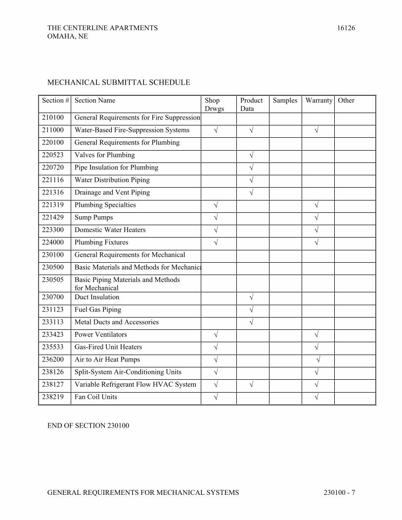
THE CENTERLINE APARTMENTS 16126OMAHA, NE
GENERAL REQUIREMENTS FOR MECHANICAL SYSTEMS 230100 - 7
MECHANICAL SUBMITTAL SCHEDULE
Section # Section Name Shop Drwgs
Product Data
Samples Warranty Other
210100 General Requirements for Fire Suppression
211000 Water-Based Fire-Suppression Systems
220100 General Requirements for Plumbing
220523 Valves for Plumbing
220720 Pipe Insulation for Plumbing
221116 Water Distribution Piping
221316 Drainage and Vent Piping
221319 Plumbing Specialties
221429 Sump Pumps
223300 Domestic Water Heaters
224000 Plumbing Fixtures
230100 General Requirements for Mechanical
230500 Basic Materials and Methods for Mechanical
230505 Basic Piping Materials and Methods for Mechanical
230700 Duct Insulation
231123 Fuel Gas Piping
233113 Metal Ducts and Accessories
233423 Power Ventilators
235533 Gas-Fired Unit Heaters
236200 Air to Air Heat Pumps
238126 Split-System Air-Conditioning Units
238127 Variable Refrigerant Flow HVAC System
238219 Fan Coil Units
END OF SECTION 230100

THE CENTERLINE APARTMENTS 16126
OMAHA, NE
BASIC MECHANICAL MATERIALS AND METHODS 230500 - 1
SECTION 230500 - BASIC MECHANICAL MATERIALS AND METHODS
PART 1 - GENERAL
1.1 RELATED DOCUMENTS
A. Drawings and general provisions of the Contract, including General and Supplementary
Conditions and Division 1 Specification Sections, apply to this Section.
1.2 SUMMARY
A. This Section includes the following basic mechanical materials and methods and shall apply to
all phases of the work specified, indicated on the drawings or required to provide for complete
installation of mechanical systems.
1. Indenting Devices and Labels
2. Grout
3. Sealants
4. Access Doors
5. Electrical Requirements
6. Motors
7. Mechanical Equipment Installation
8. Labeling and Identifying
9. Construction Layout
10. Data and Measurements
1.3 DEFINITIONS
A. Finished Spaces: Spaces other than mechanical and electrical equipment rooms, furred spaces,
pipe and duct shafts, unheated spaces immediately below roof, spaces above ceilings,
unexcavated spaces, crawl spaces, and tunnels.
B. Exposed, Interior Installations: Exposed to view indoors. Examples include finished occupied
spaces and mechanical equipment rooms.
C. Exposed, Exterior Installations: Exposed to view outdoors, or subject to outdoor ambient
temperatures and weather conditions. Examples include rooftop locations.
D. Concealed, Interior Installations: Concealed from view and protected from physical contact by
building occupants. Examples include above ceilings and in duct shafts.
E. Concealed, Exterior Installations: Concealed from view and protected from weather conditions
and physical contact by building occupants, but subject to outdoor ambient temperatures.
Examples include installations within unheated shelters.
THE CENTERLINE APARTMENTS 16126
OMAHA, NE
BASIC MECHANICAL MATERIALS AND METHODS 230500 - 2
1.4 SUBMITTALS
A. Product Data: For sealants and identification materials and devices.
B. Shop Drawings: Detail fabrication and installation for metal and wood supports and anchorage
for mechanical materials and equipment.
C. See “Submittal Schedule” at the end of Section 230100 – General Requirements for HVAC.
1.5 QUALITY ASSURANCE
A. Comply with ASME A13.1 for lettering size, length of color field, colors, and viewing angles of
identification devices.
B. Equipment Selection: Equipment of higher electrical characteristics, physical dimensions,
capacities, and ratings may be furnished provided such proposed equipment is approved in
writing and connecting mechanical and electrical services, circuit breakers, conduit, motors,
bases, and equipment spaces are increased. Additional costs shall be approved in advance by
appropriate Contract Modification for these increases. If minimum energy ratings or
efficiencies of equipment are specified, equipment must meet design and commissioning
requirements.
1.6 DELIVERY, STORAGE, AND HANDLING
A. Each contractor shall make provisions for delivery and safe storage of materials. Materials shall
be delivered in a timely manner to expedite the work.
B. Protect stored piping, supplies and equipment from cold, moisture and dirt. Elevate above
grade. Do not exceed structural capacity of floor, if stored inside.
1.7 COORDINATION
A. Coordinate mechanical equipment installation with other building components.
B. Arrange for pipe, duct and equipment spaces, chases, slots, and openings in building structure
during progress of construction to allow for mechanical installations.
C. Coordinate installation of required supporting devices and set sleeves in poured-in-place
concrete and other structural components, as they are constructed.
D. Sequence, coordinate, and integrate installations of mechanical materials and equipment for
efficient flow of the Work. Coordinate installation of large equipment requiring positioning
before closing in building.
E. Coordinate connection of mechanical systems with exterior underground and overhead utilities
and services. Comply with requirements of governing regulations, franchised service
companies, and controlling agencies.
THE CENTERLINE APARTMENTS 16126
OMAHA, NE
BASIC MECHANICAL MATERIALS AND METHODS 230500 - 3
F. Coordinate requirements for access panels and doors if mechanical items requiring access are
concealed behind finished surfaces.
G. Coordinate installation of identifying devices after completing covering and painting, if devices
are applied to surfaces. Install identifying devices before installing acoustical ceilings and
similar concealment.
H. Motors, equipment, controls, etc. shall be furnished, mounted and connected according to the
following schedule unless otherwise noted (E =Electrical Contractor, M = Mechanical
Contractor):
PART 2 - PRODUCTS
2.1 IDENTIFYING DEVICES AND LABELS
A. General: Manufacturer's standard products of categories and types required for each application
as referenced in other Division 23 Sections. If more than one type is specified for application,
selection is Installer's option, but provide one selection for each product category.
B. Equipment Nameplates: Metal nameplate with operational data engraved or stamped;
permanently fastened to equipment.
1. Data: Manufacturer, product name, model number, serial number, capacity, operating
and power characteristics, labels of tested compliances, and similar essential data.
2. Location: Accessible and visible location.
C. Engraved Plastic-Laminate Signs: ASTM D 709, Type I, cellulose, paper-base, phenolic-resin-
laminate engraving stock; Grade ES-2, black surface, black phenolic core, with white melamine
subcore, unless otherwise indicated.
1. Fabricate in sizes required for message.
2. Engraved with engraver's standard letter style, of sizes and with wording to match
equipment identification.
D. Fasteners: Self-tapping stainless-steel screws or contact-type permanent adhesive.
E. Valve Tags: 19 gauge, 1-1/2” diameter, polished brass, stamped or engraved ¼” high piping
system abbreviation in and ½” high sequenced valve numbers.
1. Valve tag fastener: solid brass wire link or beaded chain, or ‘S’-hook or size required for
proper attachment of tags to valves.
F. Snap-on Plastic Pipe Markers: Manufacturer's standard preprinted, semirigid, snap on, color-
coded, complying with ASME A13.1.
G. Pressure-Sensitive Pipe Markers: Manufacturer's standard preprinted, permanent adhesive,
color-coded, pressure-sensitive vinyl, complying with ASME A13.1.

THE CENTERLINE APARTMENTS 16126
OMAHA, NE
BASIC MECHANICAL MATERIALS AND METHODS 230500 - 4
H. Lettering and Graphics: Coordinate names, abbreviations, and other designations used in
mechanical identification, with corresponding designations indicated. Use numbers, lettering,
and wording indicated for proper identification and operation/maintenance of mechanical
systems and equipment.
Item Furnished By Set in place or
mounted by
Power wiring and
connection by
Control Wiring
and connection
by
1) Disconnect switches, thermal
overload switches, manual
operating switches
a) Furnished as part of factory
wired mechanical equipment
M M E --
b) Loose mounted E E E --
2) Transformers
a) Serving 24 Volt control
power
M(1) M E M
3) Push-button stations, pilot lights E E E E
4) Low voltage controls and
thermostats
M M M M(2)
5) Motorized valves, and float
controls for tanks and sumps
M M E M
6) Motorized control valves, damper
motors, solenoid valves, etc.
a) Line Voltage M M E M
b) Low Voltage M M M M
7) Factory pre-wired control/power
panels including remote sensing
devices
M M E M(3)
8) Electric wall and unit heaters E E E E
9) Fire protection controls M M E E
10) Fire Smoke Dampers
a) At air handling unit (24 Volt) M M M M
b) In space (120 Volt) M M E E(4)
11) Fire and smoke detectors
including relays for fan shutdown
E E E E(5)
I. Notes:
1. When control power is not available, mechanical contractor shall provide control
transformers as required to power all valves, dampers, etc.
2. Conduit rough-in for thermostats by electrical contractor where indicated on plans.
3. Remote condensing units and heat pumps control wiring including wiring of remote
sensors by mechanical. Control circuit feeders by mechanical unless shown otherwise.
4. Smoke dampers will be specified as 115 volt (verify) with wiring by Electrical Contractor
and control from the fire alarm panel. Smoke detectors furnished by electrical contractor
are required to make dampers operate.
5. Wiring from alarm contacts to alarm system by Electrical; control function wiring by
Mechanical.

THE CENTERLINE APARTMENTS 16126
OMAHA, NE
BASIC MECHANICAL MATERIALS AND METHODS 230500 - 5
2.2 GROUT
A. Nonshrink, Nonmetallic Grout: ASTM C 1107, Grade B.
1. Characteristics: Post-hardening, volume-adjusting, dry, hydraulic-cement grout,
nonstaining, noncorrosive, nongaseous, and recommended for interior and exterior
applications.
2. Design Mix: 5000-psig, 28-day compressive strength.
3. Packaging: Premixed and factory packaged.
2.3 SEALANTS
A. Polyurethane Sealant: Single component, chemical curing, non-staining, non-bleeding, capable
of continuous water immersion, non-sagging for application in vertical and horizontal joints.
Color as selected by architect.
B. Accessories: Primer, joint cleaner, joint backing and bond breaker as recommended by sealant
manufacturer to suit application.
C. Firestopping Materials: Provide firestopping material to maintain required rating of all fire-
resistive assemblies according to requirements of “Firestopping” section of this specification.
2.4 ACCESS DOORS
A. Prime Coated 14 gauge steel, flush, with screw driver operated cam lock. Frame to
accommodate construction type; size as indicated.
B. Architectural access panel with concealed hardware and gypsum board inlay. Provide with
concealed frame, latch, and hinge. Panel shall be Access Panel Solutions Inc. Bauco Plus II or
approved equal.
2.5 ELECTRICAL REQUIREMENTS
A. Compliance for HVAC Equipment
1. Comply with applicable requirements of the National Electric Code (NFPA 70)
2. Provide equipment and accessories that are listed and labeled as defined in NFPA 70
3. Comply with applicable requirements of Underwriters Laboratory (UL)
4. Comply with applicable requirements of NEMA standards
B. Electrical Wire
1. Wiring material shall be in accordance with the latest version of the National Electric
Code (NFPA 70) and all applicable local codes and carry the UL label where applicable.
2. All exposed wiring in return air plenums shall be rate cable for fire and smoke spread.

THE CENTERLINE APARTMENTS 16126
OMAHA, NE
BASIC MECHANICAL MATERIALS AND METHODS 230500 - 6
2.6 MOTORS
A. BASIC MOTOR REQUIREMENTS
1. Motors ¾ HP and Larger shall be polyphase. Motors Smaller than ¾ HP shall be single
phase unless otherwise indicated
2. Frequency Rating shall be 60 Hz. Voltage Rating is determined by voltage of circuit to
which motor is connected.
3. Service Factor: According to NEMA MG 1, unless otherwise indicated.
4. Capacity and Torque Characteristics: Rated for continuous duty and sufficient to start,
accelerate, and operate connected loads at designated speeds, in indicated environment,
with indicated operating sequence, and without exceeding nameplate ratings or
considering service factor.
5. Enclosure: Open dripproof, unless otherwise indicated.
B. POLYPHASE MOTORS
1. General
a. Design Characteristics: NEMA MG 1, Design B, Energy-Efficient Design,
unless otherwise indicated.
b. Stator: Copper windings, unless otherwise indicated. Multispeed motors
have separate winding for each speed.
c. Rotor: Squirrel cage, unless otherwise indicated.
d. Bearings: Double-shielded, prelubricated ball bearings suitable for radial
and thrust loading.
e. Temperature Rise: Match insulation rating, unless otherwise indicated.
f. Insulation: Class F, unless otherwise indicated.
2. Motors Used with Reduced-Inrush Controllers: Match wiring connection requirements
for indicated controller, with required motor leads brought to motor terminal box to suit
control method.
3. Motors Used with Variable-Frequency Controllers: Ratings, characteristics, and features
coordinated with and approved by controller manufacturer. Inverter rated motors used in
conjunction with variable speed drives shall be equipped with a shaft grounding ring.
Grounding ring shall be AEGIS Model SGR uKIT, either solid or split ring design.
Grounding ring may be epoxy mounted if manufacturer's conductive epoxy adhesive is
used.
4. Rugged-Duty Motors: Where indicated, motors are totally enclosed with 1.25 minimum
service factor, greased bearings, integral condensate drains, and capped relief vents.
Windings are insulated with nonhygroscopic material. External finish is chemical-
resistant paint over corrosion-resistant primer.
C. SINGLE-PHASE MOTORS
1. Permanent-split capacitor, Split-phase start, capacitor run or capacitor start, capacitor run
as indicated or selected by manufacturer, to suit starting torque and other requirements of
specific motor application.

THE CENTERLINE APARTMENTS 16126
OMAHA, NE
BASIC MECHANICAL MATERIALS AND METHODS 230500 - 7
2. Thermal Protection: Where indicated or required, internal protection automatically opens
power supply circuit to motor when winding temperature exceeds a safe value calibrated
to temperature rating of motor insulation. Thermal protection device automatically resets
when motor temperature returns to normal range, unless otherwise indicated.
3. Bearings: Ball-bearing type for belt-connected motors and other motors with high radial
forces on motor shaft. Sealed, prelubricated sleeve bearings for other single-phase
motors.
PART 3 - EXECUTION
3.1 EQUIPMENT INSTALLATION
A. Install equipment to provide maximum possible headroom, if mounting heights are not
indicated.
B. Install equipment according to approved submittal data. Portions of the Work are shown only in
diagrammatic form. Refer conflicts to Architect.
C. Install equipment level and plumb, parallel and perpendicular to other building systems and
components in exposed interior spaces, unless otherwise indicated.
D. Install mechanical equipment to facilitate service, maintenance, and repair or replacement of
components. Connect equipment for ease of disconnecting, with minimum interference to other
installations. Extend grease fittings to accessible locations.
E. Install equipment giving right of way to piping installed at required slope.
3.2 POSITION OF DEVICES
A. Devices shall be installed at the height indicated below unless otherwise noted. All heights of
outlets are measured from finished floor to centerline of device. Locate devices mounted on
finish surfaces with regards to furring, trim, etc. Heights may be adjusted as necessary to clear
wall mounted cabinets, electrical devices, etc. Where installed in masonry walls, mounting
heights may be adjusted to correspond to block coursing. In no case shall devices requiring
handicapped accessibility be mounted above 54”.
1. Thermostats
a. Typical Apartments: 54”
b. ANSI Type A Apartments: 44"
c. Public Areas: 44"
2. Space Sensors (without set point adjustment): 54”
3. Temperature Control Panels:
a. Not requiring occupant interface: 60”
b. Requiring occupant interface: 48"

THE CENTERLINE APARTMENTS 16126
OMAHA, NE
BASIC MECHANICAL MATERIALS AND METHODS 230500 - 8
3.3 LABELING AND IDENTIFYING
A. Piping Systems: Install pipe markers on each system. Include arrows showing normal direction
of flow.
1. Plastic markers, with application systems. Install on insulation segment if required for
hot, uninsulated piping.
2. Locate pipe markers as follows if piping is exposed in finished spaces, machine rooms,
and accessible maintenance spaces, such as shafts, tunnels, plenums, and exterior
nonconcealed locations:
a. Near each valve and control device.
b. Near each branch, excluding short takeoffs for fixtures and terminal units.
Mark each pipe at branch, if flow pattern is not obvious.
c. Near locations if pipes pass through walls, floors, ceilings, or enter
nonaccessible enclosures.
d. At access doors, manholes, and similar access points that permit view of
concealed piping.
e. Near major equipment items and other points of origination and termination.
f. Spaced at maximum of 50-foot intervals along each run. Reduce intervals to
25 feet in congested areas of piping and equipment.
g. On piping above removable acoustical ceilings, except omit intermediately
spaced markers.
B. Equipment: Install engraved plastic-laminate sign or equipment marker on or near each major
item of mechanical equipment.
C. Valve Tags:
1. Install valve tag at all valves in piping systems listed below
a. Domestic water (excluding individual fixture isolation valves)
2. Provide reproducible set of drawings indicating all valve locations.
D. Label duct access doors at fire and smoke damper locations per NFPA 90A.
E. Adjusting: Relocate identifying devices as necessary for unobstructed view in finished
construction.
3.4 FIRESTOPPING
A. Apply firestopping to all duct and pipe penetrations of fire-rated floor and wall assemblies to
achieve fire-resistance rating of the assembly.
3.5 CONCRETE BASES

THE CENTERLINE APARTMENTS 16126
OMAHA, NE
BASIC MECHANICAL MATERIALS AND METHODS 230500 - 9
A. Construct concrete bases of dimensions indicated, but not less than 3-1/2” inches larger in both
directions than supported unit. Follow supported equipment manufacturer's setting templates
for anchor bolt and tie locations. Use 3000-psig, 28-day compressive-strength concrete and
reinforcement
CUTTING AND PATCHING
B. Cut, channel, chase, and drill floors, walls, partitions, ceilings, and other surfaces necessary for
installations. Perform cutting by skilled mechanics of trades involved.
C. Repair cut surfaces to match adjacent surfaces.
3.6 CONSTRUCTION LAYOUT
A. Layout work in advance of installation using data and measurements from the site, the
appropriate architectural and structural drawings and shop drawings.
B. Confirm adequate clearance for installation, operation, maintenance and code required clearance
including items installed by other contractors.
C. If layout to provide clearance is not possible, promptly notify Architect/Engineer for
clarification.
3.7 DATA AND MEASUREMENTS
A. The data given herein and on the drawings is as accurate as could be secured. The existence and
location of construction as indicated is not guaranteed. Before beginning work investigate and
verify the existence and location of items affecting work. Obtain exact locations,
measurements, levels, etc., at the site and adapt work to actual conditions.
B. Only site measurements may be utilized in calculations. Mechanical and electrical drawings are
diagrammatic or schematic.
3.8 PAINTING AND FINISHING
A. Refer to individual sections for paint materials, surface preparation, and application of paint.
B. Do not paint piping specialties with factory-applied finish.
C. Damage and Touchup: Repair marred and damaged factory-painted finishes with materials and
procedures to match original factory finish.
3.9 ERECTION SUPPORTS AND ANCHORAGE

THE CENTERLINE APARTMENTS 16126
OMAHA, NE
BASIC MECHANICAL MATERIALS AND METHODS 230500 - 10
A. Cut, fit, and place miscellaneous metal supports accurately in location, alignment, and elevation
to support and anchor mechanical materials and equipment.
B. Field Welding: Comply with applicable codes and standards.
3.10 GROUTING
A. Install nonmetallic, non-shrink, grout for mechanical equipment base bearing surfaces, pump
and other equipment base plates, and anchors. Mix and place and cure grout according to
manufacturer's written instructions.
3.11 ACCESS
A. Provide access to all equipment, valves, controls, etc. as required for operation, repair and
maintenance.
B. Access doors shall be provided when access through ceilings, chases, etc. is not provided by
others.
3.12 ELECTRICAL WIRING
A. Install all electrical wiring in accordance with the National Electric Code and Division 26 of
this specification.
B. All line voltage wire shall be installed in metal raceways.
C. All low voltage wire in exposed in equipment rooms shall be installed in metal raceways.
END OF SECTION 230500

THE CENTERLINE APARTMENTS 16126
OMAHA, NE
BASIC MECHANICAL PIPING MATERIALS AND METHODS 230505 - 1
SECTION 230505 - BASIC MECHANICAL PIPING MATERIALS AND METHODS
PART 1 - GENERAL
1.1 RELATED DOCUMENTS
A. Drawings and general provisions of the Contract, including General and Supplementary
Conditions and Division 1 Specification Sections, apply to this Section.
1.2 SUMMARY
A. This Section includes the following basic mechanical materials and methods to complement
other Division 21, 22 and 23 Sections.
1. Piping materials and installation instructions common to mechanical piping systems.
2. Escutcheons.
3. Dielectric fittings.
4. Flexible connectors.
5. Mechanical sleeve seals.
6. Pipe hangers and supports
7. Meters and gages
B. Pipe and pipe fitting materials are specified in Division 23 piping system Sections.
1.3 DEFINITIONS
A. MSS: Manufacturer’s Standardization Society for the Valve and Fittings Industry.
B. Terminology: As defined in MSS SP-90, "Guidelines on Terminology for Pipe Hangers and
Supports."
1.4 PERFORMANCE REQUIREMENTS
A. Design support systems for piping to support multiple pipes capable of supporting combined
weight of supported systems, system contents, and test water.
1.5 SUBMITTALS
A. Product Data: For dielectric fittings, mechanical sleeve seals, and each type of pipe hanger,
channel support system component, and thermal-hanger shield insert indicated. Include scale
range, ratings, and calibrated performance curves for each meter, gage, fitting, specialty, and
accessory specified.

THE CENTERLINE APARTMENTS 16126
OMAHA, NE
BASIC MECHANICAL PIPING MATERIALS AND METHODS 230505 - 2
B. Maintenance Data: For meters and gages to include in maintenance manuals. Submit valve
schedules to include in maintenance manuals for each piping system. Valve schedule shall
indicate valve number, piping system and location of valve.
1.6 QUALITY ASSURANCE
A. Welders shall be qualified in accordance with applicable codes. Welding procedures and testing
shall comply with ANSI B31.10 “Standard for Pressure Piping. Power Piping” and AWS
Welding Handbook.
PART 2 - PRODUCTS
2.1 MANUFACTURERS
A. Available Manufacturers: Subject to compliance with requirements, manufacturers offering
products that may be incorporated into the Work include, but are not limited to, the following:
1. Dielectric Unions, Couplings, Flanges:
a. Capitol Manufacturing Co.
b. Central Plastics Co.
c. Eclipse, Inc.; Rockford-Eclipse Div.
d. Epco Sales Inc.
e. Hart Industries International, Inc.
f. Watts Industries, Inc.; Water Products Div.
g. Zurn Industries, Inc.; Wilkins Div.
2. Mechanical Sleeve Seals:
a. Calpico, Inc.
b. Metraflex Co.
c. Thunderline/Link-Seal.
3. Pipe Hangers and Supports:
a. AAA Technology and Specialties Co., Inc.
b. B-Line Systems, Inc.
c. Carpenter & Patterson, Inc.
d. Grinnell Corp. B-Line Systems, Inc.
e. Grinnell Corp.; Power-Strut Unit.
f. GS Metals Corp.
g. Michigan Hanger Co., Inc.; O-Strut Div.
h. National Pipe Hanger Corp.
i. Thomas & Betts Corp.
j. Unistrut Corp.
k. Wesanco, Inc.
l. Thermal-Hanger Shield Inserts

THE CENTERLINE APARTMENTS 16126
OMAHA, NE
BASIC MECHANICAL PIPING MATERIALS AND METHODS 230505 - 3
4. Thermometers:
a. AMETEK, Inc.; U.S. Gauge Div
b. Dresser Industries, Inc.; Instrument Div.; Ashcroft Commercial Sales
Operation.
c. Dresser Industries, Inc.; Instrument Div.; Weksler Instruments Operating
Unit.
d. Ernst Gage Co.
e. Marshalltown Instruments
f. Miljoc Corporation
g. Noshok, Inc.
h. Reotemp Instrument Corp.
i. Tel-Tru Manufacturing Co., Inc.
j. Trerice: H. O. Trerice Co.
k. Weiss Instruments, Inc.
l. Winter's Thermogauges, Inc.
5. Pressure Gages:
a. AMETEK, Inc.; U.S. Gauge Div.
b. Dresser Industries, Inc.; Instrument Div.; Ashcroft Commercial Sales
Operation.
c. Dresser Industries, Inc.; Instrument Div.; Weksler Instruments Operating
Unit.
d. Ernst Gage Co.
e. Marsh Bellofram.
f. Miljoco Corporation
g. Noshok, Inc.
h. Trerice: H. O. Trerice Co.
i. Weiss Instruments, Inc.
j. WIKA Instruments Corp.
k. Winter's Thermogauges, Inc.
6. Test Plugs:
a. Flow Design, Inc.
b. MG Piping Products Co.
c. Miljoco Corporation
d. National Meter.
e. Peterson Equipment Co., Inc.
f. Sisco Manufacturing Co.
g. Trerice: H. O. Trerice Co.
h. Watts Industries, Inc.; Water Products Div.
2.2 PIPE AND PIPE FITTINGS
A. Refer to individual Division 23 piping Sections for pipe and fitting materials and joining
methods.

THE CENTERLINE APARTMENTS 16126
OMAHA, NE
BASIC MECHANICAL PIPING MATERIALS AND METHODS 230505 - 4
B. Pipe Threads: ASME B1.20.1 for factory-threaded pipe and pipe fittings.
2.3 JOINING MATERIALS
A. Refer to individual Division 23 piping Sections for special joining materials not listed below.
B. Pipe-Flange Gasket Materials: Suitable for chemical and thermal conditions of piping system
contents.
1. ASME B16.21, nonmetallic, flat, asbestos-free, 1/8-inch maximum thickness, unless
thickness or specific material is indicated.
a. Full-Face Type: For flat-face, Class 125, cast-iron and cast-bronze flanges.
b. Narrow-Face Type: For raised-face, Class 250, cast-iron and steel flanges.
2. AWWA C110, rubber, flat face, 1/8 inch thick, unless otherwise indicated; and full-face
or ring type, unless otherwise indicated.
C. Flange Bolts and Nuts: ASME B18.2.1, carbon steel, unless otherwise indicated.
D. Plastic, Pipe-Flange Gasket, Bolts, and Nuts: Type and material recommended by piping
system manufacturer, unless otherwise indicated.
E. Solder Filler Metals: ASTM B 32.
1. Alloy Sn95 or Alloy Sn94: Approximately 95 percent tin and 5 percent silver, with 0.10
percent lead content.
2. Alloy E: Approximately 95 percent tin and 5 percent copper, with 0.10 percent
maximum lead content.
3. Alloy HA: Tin-antimony-silver-copper zinc, with 0.10 percent maximum lead content.
4. Alloy HB: Tin-antimony-silver-copper nickel, with 0.10 percent maximum lead content.
5. Alloy Sb5: 95 percent tin and 5 percent antimony, with 0.20 percent maximum lead
content.
F. Brazing Filler Metals: AWS A5.8.
1. BCuP Series: Copper-phosphorus alloys.
2. BAg1: Silver alloy.
G. Welding Filler Metals: Comply with AWS D10.12 for welding materials appropriate for wall
thickness and chemical analysis of steel pipe being welded.
H. Solvent Cements: Manufacturer's standard solvent cements for PVC Piping. ASTM D 2564.
Include primer according to ASTM F 656.
I. Flanged, Ductile-Iron Pipe Gasket, Bolts, and Nuts: AWWA C110, rubber gasket, carbon-steel
bolts and nuts.
J. Couplings: Iron-body sleeve assembly, fabricated to match OD of plain-end, pressure pipes.

THE CENTERLINE APARTMENTS 16126
OMAHA, NE
BASIC MECHANICAL PIPING MATERIALS AND METHODS 230505 - 5
1. Sleeve: ASTM A 126, Class B, gray iron.
2. Followers: ASTM A 47 malleable iron or ASTM A 536 ductile iron.
3. Gaskets: Rubber.
4. Bolts and Nuts: AWWA C111.
5. Finish: Enamel paint.
2.4 DIELECTRIC FITTINGS
A. General: Assembly or fitting with insulating material isolating joined dissimilar metals, to
prevent galvanic action and stop corrosion.
B. Description: Combination of copper alloy and ferrous; threaded, solder, plain, and weld-neck
end types and matching piping system materials.
C. Insulating Material: Suitable for system fluid, pressure, and temperature.
D. Factory-fabricated, union assembly, for 250-psig minimum working pressure at 180 deg F.
2.5 MECHANICAL SLEEVE SEALS
A. Description: Modular design, with interlocking rubber links shaped to continuously fill annular
space between pipe and sleeve. Include connecting bolts and pressure plates.
2.6 PIPING SPECIALTIES
A. Sleeves: The following materials are for wall, floor, slab, and roof penetrations:
1. Steel Sheet Metal: 0.0239-inch minimum thickness, galvanized, round tube closed with
welded longitudinal joint.
2. Steel Pipe: ASTM A 53, Type E, Grade A, Schedule 40, galvanized, plain ends.
3. Cast Iron: Cast or fabricated "wall pipe" equivalent to ductile-iron pressure pipe, with
plain ends and integral waterstop, unless otherwise indicated.
4. PVC: Manufactured, permanent, with nailing flange for attaching to wooden forms.
5. PVC Pipe: ASTM D 1785, Schedule 40.
B. Escutcheons: Manufactured wall, ceiling, and floor plates; deep-pattern type if required to
conceal protruding fittings and sleeves.
1. ID: Closely fit around pipe, tube, and insulation of insulated piping.
2. OD: Completely cover opening.
3. Stamped Steel: One piece, with set screw, spring clips, concealed hinge and chrome-
plated finish.
2.7 PIPE HANGERS AND SUPPORTS
A. Pipe Hangers, Supports, and Components: factory-fabricated components.

THE CENTERLINE APARTMENTS 16126
OMAHA, NE
BASIC MECHANICAL PIPING MATERIALS AND METHODS 230505 - 6
1. Galvanized, Metallic Coatings: For piping and equipment that will not have field-applied
finish.
2. Nonmetallic Coatings: On attachments for electrolytic protection where attachments are
in direct contact with copper tubing.
B. Channel Support Systems: MFMA-2, factory-fabricated components for field assembly.
1. Coatings: Manufacturer's standard finish, unless bare metal surfaces are indicated.
2. Nonmetallic Coatings: On attachments for electrolytic protection where attachments are
in direct contact with copper tubing.
C. Thermal-Hanger Shield Inserts: 100-psi minimum compressive-strength insulation, encased in
sheet metal shield. ASTM C 552, Type I cellular glass or water-repellent-treated,
ASTM C 533, Type I calcium silicate with vapor barrier
2.8 MISCELLANEOUS PIPE SUPPORTING MATERIALS
A. Powder-Actuated Drive-Pin Fasteners: Powder-actuated-type, drive-pin attachments with pull-
out and shear capacities appropriate for supported loads and building materials where used.
B. Mechanical-Anchor Fasteners: Insert-type attachments with pull-out and shear capacities
appropriate for supported loads and building materials where used.
C. Structural Steel: ASTM A 36/A 36M, steel plates, shapes, and bars, black and galvanized.
D. Grout: ASTM C 1107, Grade B, factory-mixed and -packaged, nonshrink and nonmetallic, dry,
hydraulic-cement grout.
2.9 THERMOMETERS, GENERAL
A. Scale Range: Temperature ranges for services listed are as follows:
1. Domestic Hot Water: 30 to 300 deg F, with 2-degree scale divisions.
2. Condenser Water: 0 to 160 deg F, with 2-degree scale divisions.
3. Chilled Water: 0 to 120 deg F, with 1-degree scale divisions.
4. Steam and Condensate: 50 to 400 deg F, with 5-degree scale divisions.
5. Heat Pump Loop Water: 0 to 160 deg F.
B. Accuracy: Plus or minus 1 percent of range span or plus or minus one scale division to
maximum of 1.5 percent of range span.
2.10 LIQUID-IN-GLASS THERMOMETERS
A. Case: Die-cast aluminum with hard powder-coat finish, acrylic front, 9 inches long.
B. Adjustable Joint: Finish to match case, 180-degree adjustment in vertical plane, 360-degree
adjustment in horizontal plane, with locking device.
THE CENTERLINE APARTMENTS 16126
OMAHA, NE
BASIC MECHANICAL PIPING MATERIALS AND METHODS 230505 - 7
C. Tube: Blue reading, organic-liquid filled with magnifying lens.
D. Scale: Satin-faced nonreflective aluminum with permanently etched markings or white finished
aluminum with black markings.
E. Stem: Die-cast aluminum for separable socket; of length to suit installation.
2.11 DIRECT-MOUNTING, FILLED-SYSTEM DIAL THERMOMETERS
A. Description: Vapor-actuated, universal-angle dial type.
B. Case: Stainless steel with 4-1/2-inch diameter, clear acrylic lens.
C. Adjustable Joint: Brass, 180-degree adjustment in vertical plane, with locking device.
D. Thermal Bulb: Copper with phosphor-bronze bourdon pressure tube.
E. Movement: Brass, precision geared.
F. Scale: Progressive, white finished aluminum with black markings.
G. Stem: Copper for separable socket; of length to suit installation.
2.12 SEPARABLE SOCKETS (THERMOWELLS)
A. Description: Fitting with protective socket for installation in threaded pipe fitting to hold fixed
thermometer stem.
1. Material: to match piping.
2. Extension-Neck Length: Nominal thickness of 2 inches, but not less than thickness of
insulation. Omit extension neck for sockets for piping not insulated.
3. Insertion Length: To extend to one-third of diameter of pipe or 2 inches into pipe.
2.13 PRESSURE GAGES
A. Description: ASME B40.1, phosphor-bronze bourdon-tube type with bottom connection; dry
type, unless liquid-filled-case type is indicated.
B. Case: Stainless steel with 4-1/2-inch diameter, clear acrylic lens.
C. Connector: Brass, NPS 1/4.
D. Scale: White-coated aluminum with permanently etched markings or white finished aluminum
with black markings.
E. Accuracy: Grade 1A, plus or minus 1 percent of full scale.

THE CENTERLINE APARTMENTS 16126
OMAHA, NE
BASIC MECHANICAL PIPING MATERIALS AND METHODS 230505 - 8
F. Range: Comply with the following:
1. Vacuum: 30 inches Hg of vacuum to 15 psig of pressure.
2. Fluids under Pressure: Two times the operating pressure.
G. Gage Fitting Valves: NPS 1/4 brass or stainless-steel needle type.
2.14 TEST PLUGS
A. Description: Brass-body test plug in NPS 1/2 fitting.
B. Body: Length as required to extend beyond insulation.
C. Pressure Rating: 500 psig minimum.
D. Core Inserts: Two self-sealing valves, suitable for inserting 1/8-inch OD probe from dial-type
thermometer or pressure gage adapter with probe.
E. Core Material for Air and Water: Nordel, good up to 350 deg F.
F. Core material for Natural Gas: Neoprene, good up to 200 deg F.
G. Test-Plug Cap: Gasketed and threaded cap, of same material as plug.
H. Test Kit: Pressure gage and adapter with probe, two 5-inch pocket testing thermometers with
magnifying lens, and protective carrying case.
1. Pressure Gage and Thermometer Ranges: Approximately two times the system's
operating conditions.
PART 3 - EXECUTION
3.1 PIPING SYSTEMS - COMMON REQUIREMENTS
A. General: Install piping as described below, unless piping Sections specify otherwise.
Individual Division 21, 22 and 23 piping Sections specify unique piping installation
requirements.
B. General Locations and Arrangements: Drawing plans, schematics, and diagrams indicate
general location and arrangement of piping systems. Indicated locations and arrangements were
used to size pipe and calculate friction loss, expansion, pump sizing, and other design
considerations.
C. Install piping at indicated slope.
D. Install components with pressure rating equal to or greater than system operating pressure.
THE CENTERLINE APARTMENTS 16126
OMAHA, NE
BASIC MECHANICAL PIPING MATERIALS AND METHODS 230505 - 9
E. Install piping in concealed interior and exterior locations, except in equipment rooms and
service areas.
F. Install piping free of sags and bends.
G. Install exposed interior and exterior piping at right angles or parallel to building walls.
Diagonal runs are prohibited, unless otherwise indicated.
H. Install piping tight to slabs, beams, joists, columns, walls, and other building elements. Allow
sufficient space above removable ceiling panels to allow for ceiling panel removal.
I. Install piping to allow application of insulation plus 1-inch clearance around insulation.
J. Locate groups of pipes parallel to each other, spaced to permit valve servicing.
K. Install fittings for changes in direction and branch connections.
L. Install couplings according to manufacturer's written instructions.
M. Install pipe escutcheons for pipe penetrations of concrete and masonry walls, wall board
partitions, and suspended ceilings.
N. Install sleeves for pipes passing through concrete and masonry walls, and concrete floor and
roof slabs.
1. Cut sleeves to length for mounting flush with both surfaces.
a. Exception: Extend sleeves installed in floors of mechanical equipment areas
or other wet areas 2 inches above finished floor level. Extend cast-iron
sleeve fittings below floor slab as required to secure clamping ring if ring is
specified.
2. Build sleeves into new walls and slabs as work progresses.
3. Install sleeves large enough to provide 1/4-inch annular clear space between sleeve and
pipe or pipe insulation. Use the following sleeve materials:
O. Aboveground, Exterior-Wall, Pipe Penetrations: Seal penetrations using sleeves and
mechanical sleeve seals. Size sleeve for 1-inch annular clear space between pipe and sleeve for
installing mechanical sleeve seals.
P. Underground, Exterior-Wall, Pipe Penetrations: Install cast-iron "wall pipes" for sleeves. Seal
pipe penetrations using mechanical sleeve seals. Size sleeve for 1-inch annular clear space
between pipe and sleeve for installing mechanical sleeve seals.
Q. Fire-Barrier Penetrations: Maintain indicated fire rating of walls, partitions, ceilings, and floors
at pipe penetrations. Seal pipe penetrations with firestopping materials
R. Verify final equipment locations for roughing-in.

THE CENTERLINE APARTMENTS 16126
OMAHA, NE
BASIC MECHANICAL PIPING MATERIALS AND METHODS 230505 - 10
S. Refer to equipment specifications in other Sections of these Specifications for roughing-in
requirements.
T. Piping Joint Construction: Join pipe and fittings as follows and as specifically required in
individual piping specification Sections:
1. Ream ends of pipes and tubes and remove burrs. Bevel plain ends of steel pipe.
2. Remove scale, slag, dirt, and debris from inside and outside of pipe and fittings before
assembly.
3. Soldered Joints: Construct joints according to AWS's "Soldering Manual," Chapter "The
Soldering of Pipe and Tube"; or CDA's "Copper Tube Handbook."
4. Brazed Joints: Construct joints according to AWS's "Brazing Handbook," Chapter "Pipe
and Tube."
5. Threaded Joints: Thread pipe with tapered pipe threads according to ASME B1.20.1.
Cut threads full and clean using sharp dies. Ream threaded pipe ends to remove burrs
and restore full ID. Join pipe fittings and valves as follows:
6. Welded Joints: Construct joints according to AWS D10.12, "Recommended Practices
and Procedures for Welding Low Carbon Steel Pipe," using qualified processes and
welding operators according to "Quality Assurance" Article.
7. Flanged Joints: Align flange surfaces parallel. Select appropriate gasket material, size,
type, and thickness for service application. Install gasket concentrically positioned.
Assemble joints by sequencing bolt tightening to make initial contact of flanges and
gaskets as flat and parallel as possible. Use suitable lubricants on bolt threads. Tighten
bolts gradually and uniformly using torque wrench.
8. Plastic Piping Solvent-Cement Joints: Clean and dry joining surfaces by wiping with
clean cloth or paper towels. Join pipe and fittings according to manufacturer’s
recommendations.
U. Piping Connections: Make connections according to the following, unless otherwise indicated:
1. Install unions, in piping 2-inch NPS and smaller, adjacent to each valve and at final
connection to each piece of equipment with 2-inch NPS or smaller threaded pipe
connection.
2. Install flanges, in piping 2-1/2-inch NPS and larger, adjacent to flanged valves and at
final connection to each piece of equipment with flanged pipe connection.
3. Install dielectric unions and flanges to connect piping materials of dissimilar metals.
3.2 HANGER AND SUPPORT APPLICATIONS
A. Comply with MSS SP-69 for pipe hanger selections and applications.
B. Comply with MSS SP-89 for fabrication and installation procedures.
C. Horizontal-Piping Hangers and Supports: Use swivel ring or clelvis type hangers.
D. Vertical-Piping: Use riser clamps.
E. Saddles and Shields: Install of length recommended by manufacturer to prevent crushing
insulation.

THE CENTERLINE APARTMENTS 16126
OMAHA, NE
BASIC MECHANICAL PIPING MATERIALS AND METHODS 230505 - 11
3.3 HANGER AND SUPPORT INSTALLATION
A. Pipe Hanger and Support Installation: Comply with MSS SP-69 and MSS SP-89. Install
hangers, supports, clamps, and attachments as required to properly support piping from building
structure.
B. Channel Support System Installation: Arrange for grouping of parallel runs of piping and
support together on field-assembled channel systems. Field assemble and install according to
manufacturer's written instructions.
C. Heavy-Duty Steel Trapeze Installation: Arrange for grouping of parallel runs of horizontal
piping and support together on field-fabricated, heavy-duty trapezes.
D. Install building attachments within concrete slabs or attach to structural steel. Install additional
attachments at concentrated loads, including valves, flanges, guides, strainers, and expansion
joints, and at changes in direction of piping. Install concrete inserts before concrete is placed;
fasten inserts to forms and install reinforcing bars through openings at top of inserts.
E. Install hangers and supports complete with necessary inserts, bolts, rods, nuts, washers, and
other accessories.
F. Install hangers and supports to allow controlled thermal movement of piping systems, to permit
freedom of movement between pipe anchors, and to facilitate action of expansion joints,
expansion loops, expansion bends, and similar units.
G. Load Distribution: Install hangers and supports so that piping live and dead loads and stresses
from movement will not be transmitted to connected equipment.
H. Pipe Slopes: Install hangers and supports to provide indicated pipe slopes and so maximum
pipe deflections allowed by ASME B31.9, "Building Services Piping," is not exceeded.
I. Insulated Piping: Comply with the following:
1. Piping Operating above Ambient Air Temperature: Clamp may project through
insulation.
2. Piping Operating below Ambient Air Temperature: Use thermal-hanger shield insert
with clamp sized to match OD of insert.
3. Do not exceed pipe stress limits according to ASME B31.9.
4. Install protection saddles or thermal hanger shields, if insulation without vapor barrier is
indicated. Fill interior voids with insulation that matches adjoining insulation.
5. Install protective shields on cold piping with vapor barrier. Shields shall span arc of 180
degrees.
J. Support vertical piping and tubing at base and at each floor.
K. Install hangers for copper tubing with the following maximum spacing and minimum rod
diameters:
1. 3/4-Inch NPS and Smaller: Maximum horizontal spacing, 60 inches with 3/8-inch
minimum rod diameter; maximum vertical spacing, 10 feet.

THE CENTERLINE APARTMENTS 16126
OMAHA, NE
BASIC MECHANICAL PIPING MATERIALS AND METHODS 230505 - 12
2. 1-Inch NPS: Maximum horizontal spacing, 72 inches with 3/8-inch minimum rod
diameter; maximum vertical spacing, 10 feet.
3. 1-1/4-Inch NPS: Maximum horizontal spacing, 72 inches with 3/8-inch minimum rod
diameter; maximum vertical spacing, 10 feet.
4. 1-1/2 and 2-Inch NPS: Maximum horizontal spacing, 96 inches with 3/8-inch minimum
rod diameter; maximum vertical spacing, 10 feet.
5. 2-1/2-Inch NPS: Maximum horizontal spacing, 108 inches with 1/2-inch minimum rod
diameter; maximum vertical spacing, 10 feet.
6. 3-Inch NPS: Maximum horizontal spacing, 10 feet with 1/2-inch minimum rod diameter;
maximum vertical spacing, 10 feet.
7. 4- and 5-Inch NPS: Maximum horizontal spacing, 10 feet with 1/2-inch minimum rod
diameter; maximum vertical spacing, 10 feet.
8. 6-Inch NPS: Maximum horizontal spacing, 10 feet with 5/8-inch minimum rod diameter;
maximum vertical spacing, 10 feet.
9. 8-Inch NPS: Maximum horizontal spacing, 10 feet with 3/4-inch minimum rod diameter;
maximum vertical spacing, 10 feet.
L. Install hangers for steel and ductile-iron piping with the following maximum spacing and
minimum rod diameters:
1. 1-1/4-Inch NPS and Smaller: Maximum horizontal spacing, 84 inches with 3/8-inch
minimum rod diameter; maximum vertical spacing, 15 feet.
2. 1-1/2-Inch NPS: Maximum horizontal spacing, 108 inches with 3/8-inch minimum rod
diameter; maximum vertical spacing, 15 feet.
3. 2-Inch NPS: Maximum horizontal spacing, 10 feet with 3/8-inch minimum rod diameter;
maximum vertical spacing, 15 feet.
4. 2-1/2-Inch NPS: Maximum horizontal spacing, 11 feet with 1/2-inch minimum rod
diameter; maximum vertical spacing, 15 feet.
5. 3-Inch NPS: Maximum horizontal spacing, 12 feet with 1/2-inch minimum rod diameter;
maximum vertical spacing, 15 feet.
6. 4- and 5-Inch NPS: Maximum horizontal spacing, 12 feet with 5/8-inch minimum rod
diameter; maximum vertical spacing, 15 feet.
7. 6-Inch NPS: Maximum horizontal spacing, 12 feet with 3/4-inch minimum rod diameter;
maximum vertical spacing, 15 feet.
8. 8- through 12-Inch NPS: Maximum horizontal spacing, 12 feet with 7/8-inch minimum
rod diameter; maximum vertical spacing, 15 feet.
M. Install hangers for PVC plastic piping with the following maximum spacing and minimum rod
diameters:
1. 2-Inch NPS and Smaller: Maximum horizontal spacing, 48 inches with 3/8-inch
minimum rod diameter; maximum vertical spacing, 48 inches.
2. 2-1/2- to 3-1/2-Inch NPS: Maximum horizontal spacing, 48 inches with 1/2-inch
minimum rod diameter; maximum vertical spacing, 48 inches.
3. 4- and 5-Inch NPS: Maximum horizontal spacing, 48 inches with 5/8-inch minimum rod
diameter; maximum vertical spacing, 48 inches.
4. 6-Inch NPS: Maximum horizontal spacing, 48 inches with 3/4-inch minimum rod
diameter; maximum vertical spacing, 48 inches.

THE CENTERLINE APARTMENTS 16126
OMAHA, NE
BASIC MECHANICAL PIPING MATERIALS AND METHODS 230505 - 13
5. 8-Inch NPS: Maximum horizontal spacing, 48 inches with 7/8-inch minimum rod
diameter; maximum vertical spacing, 48 inches.
3.4 EQUIPMENT SUPPORTS
A. Fabricate structural-steel stands to suspend equipment from structure above or to support
equipment above floor.
B. Grouting: Place grout under supports for equipment and make smooth bearing surface.
C. Cut, drill, and fit miscellaneous metal fabrications for heavy-duty steel trapezes and equipment
supports.
D. Hanger Adjustment: Adjust hangers to distribute loads equally on attachments and to achieve
indicated slope of pipe.
3.5 METER AND GAGE INSTALLATION, GENERAL
A. Install meters, gages, and accessories according to manufacturer's written instructions for
applications where used.
B. Install meters and gages adjacent to machines and equipment to allow service and maintenance.
C. Calibrate meters and gauges according to manufacturer's written instructions, after installation
3.6 THERMOMETER INSTALLATION
A. Install thermometers and adjust vertical and tilted positions.
B. Install thermometers at locations indicated on plans.
C. Install separable sockets in vertical position in piping tees where fixed thermometers are
indicated.
D. When thermometers are installed in piping 1” and smaller, install well in 1-1/4” with reducers to
prevent restriction of flow.
3.7 PRESSURE-GAGE INSTALLATION
A. Install pressure gages in piping tees with pressure-gage valve located on pipe at most readable
position.
B. Install pressure gages at locations indicated on plans and the following.
1. Discharge of each pressure-reducing valve.

THE CENTERLINE APARTMENTS 16126
OMAHA, NE
BASIC MECHANICAL PIPING MATERIALS AND METHODS 230505 - 14
END OF SECTION 230505

THE CENTERLINE APARTMENTS 16126
OMAHA, NE
DUCT INSULATION 230700 - 1
SECTION 230700 - DUCT INSULATION
PART 1 - GENERAL
1.1 RELATED DOCUMENTS
A. Drawings and general provisions of the Contract, including General and Supplementary
Conditions and Division 1 Specification Sections, apply to this Section.
1.2 SUMMARY
A. This Section includes semirigid and flexible duct, plenum; acoustical duct liner; accessories and
attachments; and sealing compounds.
1.3 SUBMITTALS
A. Product Data: Include product data description, list of materials, thickness, density, k-values
and r-values for each product type, locations, manufacturer’s installation instructions, flames
spread and smoke developed ratings.
B. See “Submittal Schedule” located at the end of Section 230100 – General Requirements for
HVAC.
1.4 QUALITY ASSURANCE
A. Fire-Test-Response Characteristics: As determined by testing materials identical to those
specified in this Section according to ASTM E 84, by a testing and inspecting agency
acceptable to authorities having jurisdiction. Factory label insulation and jacket materials and
sealer and cement material containers with appropriate markings of applicable testing and
inspecting agency.
1. Insulation Installed Indoors: Flame-spread rating of 25 or less, and smoke-developed
rating of 50 or less.
2. Insulation Installed Outdoors: Flame-spread rating of 75 or less, and smoke-developed
rating of 150 or less.
PART 2 - PRODUCTS
2.1 MANUFACTURERS
THE CENTERLINE APARTMENTS 16126
OMAHA, NE
DUCT INSULATION 230700 - 2
A. Manufacturers: Subject to compliance with requirements, provide products by one of the
following:
1. Insulation:
a. CertainTeed
b. Armaflex
c. Rubatex
d. Knauf
e. Owens-Corning
f. Halstead
g. Armstrong
h. Manville
i. Pittsburgh Corning
2.2 INSULATION MATERIALS
A. Mineral-Fiber Board Thermal Insulation: Glass fibers bonded with a thermosetting resin.
Comply with ASTM C 612, Type IB, without facing and with all-service jacket manufactured
from kraft paper, reinforcing scrim, aluminum foil, and vinyl film.
B. Mineral-Fiber Blanket Thermal Insulation: Glass fibers bonded with a thermosetting resin.
Comply with ASTM C 553, Type I, 0.75 pcf density, without facing and with all-service jacket
manufactured from kraft paper, reinforcing scrim, aluminum foil, and vinyl film.
C. Acoustical duct liner: ASTM C 518 with resin and black mat coated surface exposed to air
stream to prevent erosion of glass fibers. Thermal Conductivity (k-Value): 0.26 at 75 deg F
mean temperature. Nominal Density 1.5 lbs per cubic foot, minimum noise reduction
characteristic shall be 0.55 for 1” thickness; rated for 6000 fpm air velocity; air friction
multiplier less than 1.6 at 2000 fpm.
D. Exterior Jacket: Alumaguard 60 or equal. UV Resistant, watertight, laminated waterproofing
and vapor barrier membrane.
2.3 ACCESSORIES AND ATTACHMENTS
A. Glass Cloth and Tape: Comply with MIL-C-20079H, Type I for cloth and Type II for tape.
Woven glass-fiber fabrics, plain weave, presized a minimum of 8 oz./sq. yd..
B. Bands: 3/4 inch wide, materials compatible with jacket:
C. Wire: 0.080-inch, nickel-copper alloy; 0.062-inch, soft-annealed, stainless steel; or 0.062-inch,
soft-annealed, galvanized steel.
D. Weld-Attached Anchor Pins and Washers: Copper-coated steel pin for capacitor-discharge
welding and galvanized speed washer. Pin length sufficient for insulation thickness indicated.
THE CENTERLINE APARTMENTS 16126
OMAHA, NE
DUCT INSULATION 230700 - 3
E. Adhesive-Attached Anchor Pins and Speed Washers: Galvanized steel plate, pin, and washer
manufactured for attachment to duct and plenum with adhesive. Pin length sufficient for
insulation thickness indicated.
2.4 VAPOR RETARDERS
A. Mastics: Materials recommended by insulation material manufacturer that are compatible with
insulation materials, jackets, and substrates.
PART 3 - EXECUTION
3.1 EXAMINATION AND PREPARATION
A. Examine substrates and conditions for compliance with requirements for installation and other
conditions affecting performance of insulation application. Proceed with installation only after
unsatisfactory conditions have been corrected.
B. Surface Preparation: Clean and dry surfaces to receive insulation. Remove materials that will
adversely affect insulation application.
3.2 MINERAL-FIBER INSULATION APPLICATION
A. Apply insulation materials, accessories, and finishes according to the manufacturer's written
instructions; with smooth, straight, and even surfaces; and free of voids throughout the length of
ducts and fittings.
B. Refer to schedules at the end of this Section for materials, forms, jackets, and thicknesses
required for each duct system.
C. Seal joints and seams with vapor-retarder mastic on insulation indicated to receive a vapor
retarder.
D. Apply insulation with tight longitudinal seams and end joints. Bond seams and joints with
adhesive recommended by the insulation material manufacturer.
E. Apply insulation with the least number of joints practical.
F. Apply insulation over fittings and specialties, with continuous thermal and vapor-retarder
integrity, unless otherwise indicated.
G. Hangers and Anchors: Where vapor retarder is indicated, seal penetrations in insulation at
hangers, supports, anchors, and other projections with vapor-retarder mastic. Apply insulation
continuously through hangers and around anchor attachments.
H. Apply insulation with integral jackets as follows:

THE CENTERLINE APARTMENTS 16126
OMAHA, NE
DUCT INSULATION 230700 - 4
1. Pull jacket tight and smooth.
2. Joints and Seams: Cover with tape and vapor retarder as recommended by insulation
material manufacturer to maintain vapor seal.
3. Vapor-Retarder Mastics: Where vapor retarders are indicated, apply mastic on seams and
joints and at ends adjacent to duct flanges and fittings.
I. Roof Penetrations: Apply insulation for interior applications to a point even with top of roof
flashing.
J. Interior Wall and Partition Penetrations: Apply insulation continuously through walls and
partitions, except fire-rated walls and partitions.
K. Fire-Rated Wall and Partition Penetrations: Terminate insulation at fire/smoke damper sleeves
for fire-rated wall and partition penetrations.
L. Floor Penetrations: Terminate insulation at underside of floor assembly and at floor support at
top of floor.
M. Secure insulation with adhesive and anchor pins and speed washers.
3.3 SHOP APPLICATION OF LINER IN RECTANGULAR DUCTS
A. Adhere a single layer of indicated thickness of duct liner with 90 percent coverage of adhesive
at liner contact surface area. Multiple layers of insulation to achieve indicated thickness are
prohibited.
B. Butt transverse joints without gaps and coat joint with adhesive.
C. Fold and compress liner in corners of rectangular ducts or cut and fit to ensure butted-edge
overlapping.
D. Do not apply liners in rectangular ducts with longitudinal joints, except at corners of ducts,
unless duct size and standard liner product dimensions make longitudinal joints necessary.
E. Secure liner with mechanical fasteners 4 inches from corners and at intervals not exceeding 12
inches transversely around perimeter; at 3 inches from transverse joints and at intervals not
exceeding 18 inches longitudinally.
F. Secure transversely oriented liner edges facing the airstream with metal nosings that have either
channel or "Z" profile or are integrally formed from duct wall.
G. Ductwork sizes indicated on drawings are the free area size. Ductwork sizes shall be increased
to accommodate the addition of liner to maintain the plan indicated free area size.
3.4 DUCT AND PLENUM APPLICATION SCHEDULE
A. Items Not Insulated: Unless otherwise indicated, do not apply insulation to the following
systems, materials, and equipment:

THE CENTERLINE APARTMENTS 16126
OMAHA, NE
DUCT INSULATION 230700 - 5
1. Fibrous-glass ducts.
2. Factory-insulated flexible ducts.
3. Factory-insulated plenums, casings, terminal boxes, and filter boxes and sections.
4. Flexible connectors.
5. Vibration-control devices.
6. Testing agency labels and stamps.
7. Nameplates and data plates.
8. Access panels and doors in air-distribution systems.
B. Service: SUPPLY AIR – Rectangular, routed in floor/ceiling assembly or exposed within
building envelope (not routed in attic).
1. Thickness / Material: None
2. Minimum R-Value: NA
3. Vapor Retarder Required: NA
C. Service: SUPPLY AIR – Rectangular, routed in attic.
1. Thickness / Material: 3” Mineral-fiber blanket.
2. Minimum R-Value: R8
3. Vapor Retarder Required: Yes.
D. Service: SUPPLY AIR –Round runouts, routed in floor/ceiling assembly.
1. Thickness / Material:
a. Galvanized sheet steel duct: No insulation required
b. Flex duct: Pre-insulated with R5 insulation
2. Minimum R-Value: R5 for pre-insulated flex duct
3. Vapor Retarder Required: NA
E. Service: SUPPLY AIR –Round runouts, galvanized sheet steel, exposed within building
envelope
1. Thickness / Material: None
2. Minimum R-Value: NA
3. Vapor Retarder Required: NA.
4. No exposed flex duct allowed
F. Service: SUPPLY AIR –Round runouts, routed in attic.
1. Thickness / Material:
a. Galvanized sheet steel duct: 3” Mineral-fiber blanket.
b. Flex duct: Pre-insulated R8 insulation
2. Minimum R-Value: R8
3. Vapor Retarder Required: Yes.

THE CENTERLINE APARTMENTS 16126
OMAHA, NE
DUCT INSULATION 230700 - 6
G. Service: RETURN AIR – Rectangular, in floor/ceiling assembly or exposed in space within
building envelope (not routed in attic).
1. Thickness / Material: None.
2. Minimum R-Value: NA
3. Vapor Retarder Required: NA
H. Service: RETURN AIR - Rectangular, routed in attic.
1. Thickness / Material: 3” Mineral-fiber blanket.
2. Minimum R-Value: R8
3. Vapor Retarder Required: Yes.
I. Service: OUTSIDE AIR
1. Thickness / Material: 2” Mineral-fiber blanket.
2. Minimum R-Value: R5
3. Vapor Retarder Required: Yes.
J. Service: EXHAUST AIR
1. Thickness / Material: None
2. Minimum R-Value: NA
3. Vapor Retarder Required: NA
END OF SECTION 230700
THE CENTERLINE APARTMENTS 16126
OMAHA, NE
FUEL GAS PIPING 231123 - 1
SECTION 231123 - FUEL GAS PIPING
PART 1 - GENERAL
1.1 RELATED DOCUMENTS
A. Drawings and general provisions of the Contract, including General and Supplementary
Conditions and Division 1 Specification Sections, apply to this Section.
1.2 SUMMARY
A. This Section includes fuel gas piping, specialties, and accessories within the building.
1.3 PROJECT CONDITIONS
A. Gas System Pressures: Two pressure ranges. Primary pressure is more than 0.5 psig but not
more than 2.0 psig, and is reduced to secondary pressure of 0.5 psig or less.
B. Design values of fuel gas supplied for these systems are; Nominal Heating Value of 1000
Btu/cu. ft. and Nominal Specific Gravity: 0.6.
1.4 SUBMITTALS
A. Product Data: For the following:
1. Specialty valves. Include pressure rating, capacity, settings, and electrical connection
data of selected models.
2. Pressure regulators. Include pressure rating, capacity, and settings of selected models.
B. Maintenance Data: For natural gas specialties and accessories to include in maintenance
manuals.
C. See “Submittal Schedule” located at the end of Section 230100 – General Requirements for
HVAC.
1.5 QUALITY ASSURANCE
A. Electrical Components and Devices: Listed and labeled as defined in NFPA 70, Article 100, by
testing agency acceptable to authorities having jurisdiction, and marked for intended use.
B. ANSI Standard: Comply with ANSI Z223.1, "National Fuel Gas Code."
THE CENTERLINE APARTMENTS 16126
OMAHA, NE
FUEL GAS PIPING 231123 - 2
C. UL Standard: Provide components listed in UL's "Gas and Oil Equipment Directory" if
specified to be UL listed.
PART 2 - PRODUCTS
2.1 MANUFACTURERS
A. Manufacturers: Subject to compliance with requirements, provide products by one of the
following:
1. Pressure Regulators:
a. Fisher Controls International, Inc.
b. Maxitrol Co.
2.2 PIPES, TUBES, FITTINGS, AND JOINING MATERIALS
A. Steel Pipe: ASTM A 53; Type E or S; Grade B; Schedule 40; black.
1. Malleable-Iron Threaded Fittings: ASME B16.3, Class 150, standard pattern, with
threaded ends according to ASME B1.20.1.
2. Unions: ASME B16.39, Class 150, malleable iron with brass-to-iron seat, ground joint,
and threaded ends according to ASME B1.20.1.
3. Cast-Iron Flanges and Flanged Fittings: ASME B16.1, Class 125.
4. Steel Welding Fittings: ASME B16.9, wrought steel or ASME B16.11, forged steel.
5. Steel Threaded Fittings: ASME B16.11, forged steel with threaded ends according to
ASME B1.20.1.
6. Joint Compound and Tape: Suitable for natural gas.
7. Steel Flanges and Flanged Fittings: ASME B16.5.
8. Gasket Material: Thickness, material, and type suitable for natural gas.
B. Hard Copper Tube: ASTM B 88, Type L, water tube, drawn temper.
1. Copper Fittings: ASME B16.22, wrought copper, streamlined pattern.
2. Brazing Filler Metals: AWS A5.8, Silver Classification BAg-1. Filler metal containing
phosphorus is prohibited.
3. Bronze Flanges and Flanged Fittings: ASME B16.24, Class 150.
4. Gasket Material: Thickness, material, and type suitable for natural gas.
C. Transition Fittings: Type, material, and end connections to match piping being joined.
D. Common Joining Materials: Refer to Division 23 Section "Basic Materials and Methods for
HVAC" for joining materials not in this Section.
2.3 PIPING SPECIALTIES AND VALVES

THE CENTERLINE APARTMENTS 16126
OMAHA, NE
FUEL GAS PIPING 231123 - 3
A. Flexible Connectors: ANSI Z21.24, copper alloy.
B. Quick-Disconnect Devices: ANSI Z21.41, convenience outlets and matching plug connector.
C. Valves, NPS 2 and Smaller: Threaded ends according to ASME B1.20.1 for pipe threads.
D. Valves, NPS 2-1/2 and Larger: Flanged ends according to ASME B16.5 for steel flanges and
according to ASME B16.24 for copper and copper-alloy flanges.
E. Gas Stops: Bronze body with AGA stamp, plug type with bronze plug and flat or square head,
ball type with chrome-plated brass ball and lever handle, or butterfly valve with stainless-steel
disc and fluorocarbon elastomer seal and lever handle; 2-psig minimum pressure rating.
F. Gas Valves, NPS 2 and Smaller: ASME B16.33 and IAS-listed bronze body and 125-psig
pressure rating.
G. General-Duty Valves, NPS 2-1/2 and Larger: ASME B16.38, cast-iron body, suitable for fuel
gas service, with "WOG" indicated on valve body, and 125-psig pressure rating.
1. Gate Valves: MSS SP-70, OS&Y type with solid wedge.
2. Butterfly Valves: MSS SP-67, lug type with lever handle.
2.4 PRESSURE REGULATORS
A. Description: Single stage and suitable for fuel gas service. Include steel jacket and corrosion-
resistant components, elevation compensator, and atmospheric vent.
1. NPS 2 and Smaller: Threaded ends according to ASME B1.20.1 for pipe threads.
2. NPS 2-1/2 and Larger: Flanged ends according to ASME B16.5 for steel flanges and
according to ASME B16.24 for copper and copper-alloy flanges.
3. Line Pressure Regulators: ANSI Z21.80 with 2-psig- minimum inlet pressure rating.
4. Appliance Pressure Regulators: ANSI Z21.18. Regulator may include vent limiting
device, instead of vent connection, if approved by authorities having jurisdiction.
PART 3 - EXECUTION
3.1 PIPING APPLICATIONS
A. Flanges, unions, transition, and special fittings with pressure ratings same as or higher than
system pressure rating may be used in applications below, unless otherwise indicated.
B. Fuel Gas Piping, Use one of the following:
1. NPS 2 and Smaller Steel pipe, malleable-iron threaded fittings, and threaded joints.
2. NPS 2-1/2 and Larger: Steel pipe, steel welding fittings, and welded joints.
3. Hard copper tube, copper fittings, and brazed joints.

THE CENTERLINE APARTMENTS 16126
OMAHA, NE
FUEL GAS PIPING 231123 - 4
C. Underground Fuel Gas Piping: Steel pipe, steel welding fittings, and welded joints. Encase in
containment conduit of steel pipe, steel welding fittings, and welded joints.
3.2 PIPING INSTALLATION
A. Refer to Division 23 Section "Basic Piping Materials and Methods for HVAC" for basic piping
installation requirements.
B. Install fuel gas piping per NFPA 54 “National Fuel Gas Code” and Metropolitan Utilities
District Rules and Regulations.
C. Concealed Locations: Except as specified below, install concealed gas piping in airtight conduit
constructed of Schedule 40, seamless, black steel pipe with welded joints. Vent conduit to
outside and terminate with screened vent cap.
1. Above-Ceiling Locations: Gas piping may be installed in accessible spaces, subject to
approval of authorities having jurisdiction, whether or not such spaces are used as
plenums. Do not locate valves above ceilings.
2. In Partitions: Do not install concealed piping in solid partitions. Protect tubing from
physical damage when installed inside partitions or hollow walls. Piping may pass
through partitions or walls.
3. Prohibited Locations: Do not install gas piping in or through circulating air ducts, clothes
or trash chutes, chimneys or gas vents (flues), ventilating ducts, or dumbwaiter or
elevator shafts.
D. Drips and Sediment Traps: Install drips at points where condensate may collect. Include outlets
of service meters. Locate where readily accessible for cleaning and emptying. Do not install
where condensate would be subject to freezing.
1. Construct drips and sediment traps using tee fitting with bottom outlet plugged or capped.
Use minimum-length nipple of 3 pipe diameters, but not less than 3 inches long, and
same size as connected pipe. Install with space between bottom of drip and floor for
removal of plug or cap.
E. Conceal pipe installations in walls, pipe spaces, utility spaces, above ceilings, below grade or
floors, and in floor channels, unless indicated to be exposed to view.
F. Install fuel gas piping at uniform grade of 0.1 percent slope upward toward risers.
G. Use eccentric reducer fittings to make reductions in pipe sizes. Install fittings with level side
down.
H. Connect branch piping from top or side of horizontal piping.
I. Install unions in pipes NPS 2 and smaller, adjacent to each valve, at final connection to each
piece of equipment, and elsewhere as indicated. Unions are not required on flanged devices.
Install flanges on valves, specialties, and equipment having NPS 2-1/2 and larger connections.

THE CENTERLINE APARTMENTS 16126
OMAHA, NE
FUEL GAS PIPING 231123 - 5
J. Install corrugated, stainless-steel tubing system according to manufacturer's written instructions.
Include striker plates to protect tubing from puncture where tubing is restrained and cannot
move.
K. Install strainer on inlet of each line pressure regulator and automatic and electrically operated
valve.
L. Install vent piping for gas pressure regulators and gas trains, extend outside building, and vent
to atmosphere. Terminate vents with turned-down, reducing-elbow fittings with corrosion-
resistant insect screens in large end.
M. Install piping adjacent to appliances to allow service and maintenance.
N. Connect piping to appliances using gas with shutoff valves and unions. Install valve upstream
from and within 72 inches of each appliance. Install union downstream from valve.
3.3 FIELD QUALITY CONTROL
A. Inspect, test, and purge piping according to ANSI Z223.1, Part 4 "Inspection, Testing, and
Purging," and requirements of authorities having jurisdiction.
B. Repair leaks and defects with new materials and retest system until satisfactory results are
obtained.
C. Adjust controls and safety devices. Replace damaged and malfunctioning controls and safety
devices.
END OF SECTION 231123
THE CENTERLINE APARTMENTS 16126
OMAHA, NE
METAL DUCTS AND ACCESSORIES 233113 - 1
SECTION 233113 - METAL DUCTS AND ACCESSORIES
PART 1 - GENERAL
1.1 RELATED DOCUMENTS
A. Drawings and general provisions of the Contract, including General and Supplementary
Conditions and Division 1 Specification Sections, apply to this Section.
1.2 SUMMARY
A. This Section includes metal ducts and accessories for heating, ventilating, and air-conditioning
systems, diffusers, registers and grilles, and gas vents.
1.3 DEFINITIONS
A. Pressure Classification for Ductwork: As defined by to SMACNA's "HVAC Duct Construction
Standards--Metal and Flexible” and applicable codes.
1. Low Pressure: Maximum 2500 fpm velocity; maximum 2.0” WG positive or –2.0” WG
negative static pressure class.
2. Medium Pressure: Maximum 4000 fpm velocity; maximum 4.0” WG positive or –3.0”
WG negative static pressure class.
1.4 SUBMITTALS
A. Product data including product construction, installation instructions and performance data for
the following:
1. Sealing materials.
2. Backdraft dampers.
3. Manual-volume dampers.
4. Fire and smoke dampers.
5. Duct-mounted access doors and panels.
6. Flexible ducts
7. Diffuser’s Registers & Grilles
8. Gas Vents
B. No requirement for shop drawings if after examining the contract documents and actual
conditions, contractor agrees system can be installed as shown.
C. Shop Drawings: Show details of the following:

THE CENTERLINE APARTMENTS 16126
OMAHA, NE
METAL DUCTS AND ACCESSORIES 233113 - 2
1. Fabrication, assembly, and installation, including plans, elevations, sections, components,
and attachments to other work.
2. Duct layout indicating pressure classifications and sizes on plans.
3. Fittings.
4. Reinforcement and spacing.
5. Seam and joint construction.
6. Penetrations through fire-rated and other partitions.
7. Terminal unit, coil, and humidifier installations.
8. Hangers and supports, including methods for building attachment, vibration isolation,
seismic restraints, and duct attachment.
D. Field Test Reports: Indicate and interpret test results for compliance with performance
requirements.
E. Record Drawings: Indicate actual routing, fitting details, reinforcement, support, and installed
accessories and devices.
F. See “Submittal Schedule” located at the end of Section 230100 – General Requirements for
HVAC.
1.5 QUALITY ASSURANCE
A. Comply with NFPA 90A, "Installation of Air Conditioning and Ventilating Systems," unless
otherwise indicated.
PART 2 - PRODUCTS
2.1 MANUFACTURERS
A. Manufacturers: Subject to compliance with requirements, provide products by one of the
following:
1. Backdraft and Volume Dampers
a. Greenheck
b. Air Balance
c. American Warming
d. Cesco
e. Louvers and Dampers, Inc.
f. Penn
g. Prefco
h. Carnes
i. Ruskin
j. Vent Products
2. Fire and Smoke Dampers

THE CENTERLINE APARTMENTS 16126
OMAHA, NE
METAL DUCTS AND ACCESSORIES 233113 - 3
a. Greenheck
b. Air Balance
c. American Warming
d. Cesco
e. Louvers and Dampers, Inc.
f. Penn
g. Pottorff
h. Prefco
i. Carnes
j. Ruskin
k. Vent Products
l. Nailor Industries
3. Duct Silencers
a. Industrial Acoustics
b. Rink
c. Aerosonics
d. Commercial Acoustics
e. Semco
f. Vibro-Acoustics
g. United McGill
h. Dynasonics
i. Transonics
4. Flexible Ducts
a. Flexible Air Products
b. Flexmaster
c. Thermaflex
d. Certainteed
e. Wiremold
f. General Flex Corp
g. H.K. Porter
5. Duct Access Doors
a. Air Balance
b. American Warming
c. Cesco
d. Ventfrabrics
e. Penn
f. Prefco
g. Carnes
h. Ruskin
i. Kees
j. United McGill
k. Nailor Industries

THE CENTERLINE APARTMENTS 16126
OMAHA, NE
METAL DUCTS AND ACCESSORIES 233113 - 4
6. Diffusers, Registers, Grilles
a. Carnes
b. J & J Register
c. Krueger
d. Reliable
e. Price
f. Tuttle and Bailey
g. Metal-Aire
h. Titus
i. Hart and Cooly
j. Anemostat
k. Nailor Industies
7. Louvers
a. American Warming
b. Dowco
c. Louvers and Dampers, Inc.
d. Airline
e. Greenheck
f. Ruskin
g. Aerolite
h. Vent Products
i. Arrow
j. Reliable
k. Pottorff
8. Roof Hoods
a. Acme
b. Greenheck
c. Cook
d. Louvers and Dampers, Inc.
e. Carnes
f. ILG
g. Penn
9. Gas Vents:
a. American Metal Products; a Masco Company.
b. General Products Co.; Air-Jet Div.
c. Hart & Cooley, Inc.
d. Metal Fab
e. Selkirk Metalbestos.
f. Simpson Dura-Vent Co., Inc.
g. United McGill Corp.; Airflow Group.
h. Van-Packer Co.

THE CENTERLINE APARTMENTS 16126
OMAHA, NE
METAL DUCTS AND ACCESSORIES 233113 - 5
2.2 SHEET METAL MATERIALS
A. Galvanized, Sheet Steel: Lock-forming quality; ASTM A 653/A 653M, G90 coating
designation; mill-phosphatized finish for surfaces of ducts exposed to view.
B. Reinforcement Shapes and Plates: Galvanized steel reinforcement where installed on
galvanized, sheet metal ducts; compatible materials for aluminum and stainless-steel ducts.
2.3 SEALANT MATERIALS
A. Duct Sealant: UL classified, non-combustible, flame spread 25 or less, smoke developed rating
of 540 or less, resistant to water, pressure rupture rating of 16” WG minimum, suitable for use
alone or with tape, application an operational temperature ranges appropriate for usage.
2.4 MANUFACTURED DUCT JOINTS
A. Manufactured duct joining system to consistent of roll formed angles, corner pieces, metal
cleats and gasket material. Construct and join ductwork in accordance with the latest
SMACNA test data and joint reinforcement schedule corresponding to duct gauge used. Corners
to be down set design, no bolt design except bolting is required for medium pressure
applications. Reinforcements requirement for sheet metal to comply with latest SMACNA for
manufactured duct Joining technique appropriate to get to pressure class.
2.5 BACKDRAFT DAMPERS
A. Dampers to be multi-blade, parallel action, counter-balanced backdraft dampers of galvanized
steel or extruded aluminum, with center pivoted blades linked together with blade edge seals,
brass or steel bearings, and plated steel pivot pin.
2.6 MANUAL-VOLUME DAMPERS
A. Fabricate in accordance with latest edition of SMACNA HVAC Duct Construction Standards –
Metal and Flexible and as indicated.
B. Fabricate single blade dampers for duct sizes 9 ½: high x 30” width maximum. Single blade
dampers to have spring end bearing regulator. Provide end brace for static pressure greater than
2.0” WG. Provide end brace for static pressure greater than 2.0”.
C. Fabricate multi-blade damper of opposed blade pattern using minimum 16 gauge steel with
maximum blade sizes 6” x 48”. Where width exceeds 48”, provide regulator at both ends.
Assemble center and edge crimped blades in 16 gauge channel frame with suitable hardware.
Blades and frame to be galvanized or prime coated steel except where indicated for special
application.
D. Provide end bearings with end seals for pressure class required except in round duct 12” in
diameter and smaller.

THE CENTERLINE APARTMENTS 16126
OMAHA, NE
METAL DUCTS AND ACCESSORIES 233113 - 6
2.7 FIRE DAMPERS
A. General: Labeled to UL 555, One and one-half hours fire rating with 165ºF fusible link unless
otherwise indicated.
B. Frame: SMACNA Type A with blades in airstream; fabricated with roll-formed, 0.034-inch-
thick galvanized steel; with mitered and interlocking corners. Allowed only if duct free area loss
is less than 5%.
C. Frame: SMACNA Type B with blades out of airstream; fabricated with roll-formed, 0.034-
inch- thick galvanized steel; with mitered and interlocking corners.
D. Mounting Sleeve: Factory- or field-installed galvanized, sheet steel.
1. Minimum Thickness: 0.052 inch or 0.138 inch thick as indicated, and length to suit
application.
2. Exceptions: Omit sleeve where damper frame width permits direct attachment of
perimeter mounting angles on each side of wall or floor, and thickness of damper frame
complies with sleeve requirements.
E. Mounting Orientation: Vertical or horizontal as indicated.
F. Blades: Roll-formed, interlocking, 0.034-inch- thick, galvanized, sheet steel. In place of
interlocking blades, use full-length, 0.034-inch- thick, galvanized steel blade connectors.
G. Horizontal Dampers: Include a blade lock and stainless-steel negator closure spring.
2.8 CEILING FIRE DAMPERS
A. General: Labeled to UL 555C, ; comply with construction details for tested floor- and roof-
ceiling assemblies as indicated in UL's "Fire Resistance Directory."
B. Frame: 0.040-inch- thick, galvanized, sheet steel; round or rectangular; style to suit ceiling
construction.
C. Blades: 0.034-inch- thick, galvanized, sheet steel with nonasbestos refractory insulation.
D. Volume Adjustment: UL-labeled, fusible volume-control adjustment.
E. Fusible Link: Replaceable, 165 deg F rated unless otherwise indicated.
2.9 SMOKE DAMPERS
A. General: Labeled to UL 555S. Combination fire and smoke dampers shall be labeled for one-
and-one-half-hour rating to UL 555.
B. Fusible Link: Replaceable, 165 deg F unless otherwise as indicated.
THE CENTERLINE APARTMENTS 16126
OMAHA, NE
METAL DUCTS AND ACCESSORIES 233113 - 7
C. Frame and Blades: 0.064-inch- thick, galvanized, sheet steel.
D. Mounting Sleeve: Factory-installed, 0.052-inch- thick, galvanized, sheet steel; length to suit
wall or floor application.
E. Damper Motors: 115 V, single phase, 60 Hz., provide for modulating or two-position action per
application.
2.10 DUCT SILENCERS
A. General: Factory-fabricated and -tested, round or rectangular silencer with performance
characteristics and physical requirements as indicated.
B. Fire Performance: Adhesives, sealers, packing materials, and accessory materials shall have
fire ratings not exceeding 25 for flame spread and 50 for smoke developed when tested
according to ASTM E 84.
C. Fabricate casings with a minimum of 0.034-inch- thick, solid sheet metal for outer casing and
0.022-inch- thick, perforated sheet metal for inner casing.
D. Sheet Metal Perforations: 1/8-inch diameter for inner casing and baffle sheet metal.
E. Fill Material: Inert, vermin-proof and moisture proof material, packed under not less than 5
percent compression.
F. Fabricate silencers to form rigid units that will not pulsate, vibrate, rattle, or otherwise react to
system pressure variations.
G. Silencer acoustical performance as indicated. Test results of manufacture’s standard unit
substantiated by a nationally recognized independent test laboratory approved by AMCA.
2.11 TURNING VANES
A. Fabricate to comply with SMACNA's "HVAC Duct Construction Standards--Metal and
Flexible."
B. Manufactured Turning Vanes: Fabricate of 1-1/2-inch- wide, curved blades set 3/4 inch o.c.;
support with bars perpendicular to blades set 2 inches on center; and set into side strips suitable
for mounting in ducts.
2.12 DUCT-MOUNTED ACCESS DOORS AND PANELS
A. General: Fabricate doors and panels airtight and suitable for duct pressure class.
B. Frame: Galvanized, sheet steel, with bend-over tabs and foam gaskets.

THE CENTERLINE APARTMENTS 16126
OMAHA, NE
METAL DUCTS AND ACCESSORIES 233113 - 8
C. Door: Double-wall, galvanized, sheet metal construction with insulation fill and thickness, and
number of hinges and locks as indicated for duct pressure class. Include vision panel where
indicated. Include 1-by-1-inch butt or piano hinge and cam latches.
D. Seal around frame attachment to duct and door to frame with neoprene or foam rubber.
E. Insulation: 1-inch- thick, fibrous-glass or polystyrene-foam board.
F. Label: Label access doors at fire and smoke damper locations per NFPA 90A.
2.13 FLEXIBLE CONNECTORS
A. General: Flame-retarded or noncombustible fabrics, coatings, and adhesives complying with
UL 181, Class 1.
B. Neoprene double-coated woven glass fibber fabric in accordance with NFPA 90A, suitable for
temperatures and pressures of application, approximately 6” wide, crimped into metal edge
strip.
2.14 FLEXIBLE DUCTS
A. General: Comply with UL 181, Class 1.
B. Factory-fabricated, insulated, round duct, with an outer jacket enclosing glass-fiber insulation
around a continuous inner liner.
1. Reinforcement: Steel-wire helix encapsulated in inner liner.
2. Outer Jacket: Polyethylene film or Glass-reinforced, silver Mylar with a continuous
hanging tab, integral fibrous-glass tape, and nylon hanging cord.
3. Inner Liner: Polyethylene film.
C. Pressure Rating: 4-inch wg positive, 3/4-inch wg negative.
D. Minimum R-value: R-5 for ducts inside building envelope. R-8 for ducts in unconditioned
spaces.
E. Un-insulated flex duct is not allowed for the project
2.15 DIFFUSER, REGISTERS AND GRILLES
A. General: Sizes, types and capacities as indicated. Verify ceiling and wall frame types and
dimensions from architectural drawings. Factory baked enamel finish with color selected by
Architect unless otherwise indicated.
B. Diffusers: Circular, square, or rectangular air distribution outlet comprised of deflecting
members discharging supply air in various directions and planes and arranged to promote
mixing of primary air with secondary room air. Opposed blade dampers.

THE CENTERLINE APARTMENTS 16126
OMAHA, NE
METAL DUCTS AND ACCESSORIES 233113 - 9
C. Grilles: Streamlined blades, single or double deflection as indicated.
D. Registers: Combination grille and opposed damper assembly.
2.16 LOUVERS
A. Ruskin ELF375DX (unless noted otherwise on plans), Extruded aluminum; 4” deep frame,
drainable and storm-proof blade configuration, 0.90” frame and 0.81” nominal wall thickness
blades, 3 ½” blade spacing, 50% minimum free area based on 48”x 48” louver size; ¾”
aluminum mesh birdscreen. Finish baked enamel, color selected by architect.
2.17 LOUVER BLANK-OFF PANELS
A. Double wall construction with minimum 22 gauge galvanized steel sheet metal and 2” rigid
insulation. Paint louver size flat black. Seal weathertight to frame.
2.18 ROOF HOODS
A. Aluminum construction; 19 gauge x ½” galvanized mesh screen; motorized damper, 12” roof
curb. Intake shall be 20” minimum above roof.
B. Intake hoods shall be designed for intake velocity of 50% or neck. Relief hoods shall be
designed for equal velocity to neck.
2.19 STEEL, POSITIVE-PRESSURE, DOUBLE-WALL VENTS
A. Description: Double-wall metal stacks complying with NFPA 211, suitable for use with
building heating equipment burning gas, solid, or liquid fuels.
B. Construction: Inner and outer metal shells separated by at least 1/2-inch airspace, with positive
sealing joints.
C. Inner Shell: ASTM A 666, Type 304 stainless steel, 0.035 inch thick.
D. Outer Jacket: Aluminum-coated steel, 0.025 inch thick.
E. Accessories: Tees, elbows, increasers, draft hood connectors, termination, adjustable roof
flashing, storm collar, support assembly, thimbles, firestop spacers, and fasteners; fabricated of
similar materials and designs as vent-pipe straight sections.
2.20 ACCESSORY HARDWARE
A. Flexible Duct Clamps: Stainless-steel band with cadmium-plated hex screw to tighten band
with a worm-gear action, in sizes 3 to 18 inches to suit duct size.
THE CENTERLINE APARTMENTS 16126
OMAHA, NE
METAL DUCTS AND ACCESSORIES 233113 - 10
B. Adhesives: High strength, quick setting, neoprene based, waterproof, and resistant to gasoline
and grease.
2.21 HANGERS AND SUPPORTS
A. Building Attachments: Concrete inserts, powder-actuated fasteners, or structural-steel fasteners
appropriate for building materials.
B. Hanger Materials: Galvanized, sheet steel or round, threaded steel rod. Comply with
SMACNA's "HVAC Duct Construction Standards--Metal and Flexible" for sheet steel width
and thickness and for steel rod diameters
C. Duct Attachments: Sheet metal screws, blind rivets, or self-tapping metal screws; compatible
with duct materials.
PART 3 - EXECUTION
3.1 DUCT FABRICATION
A. General: Fabricate ducts, elbows, transitions, offsets, branch connections, and other
construction with galvanized, sheet steel, according to SMACNA's "HVAC Duct Construction
Standards--Metal and Flexible." Comply with requirements for metal thickness, reinforcing
types and intervals, tie-rod applications, and joint types and intervals.
B. Low Pressure duct
1. Seams and Joints (Rectangular Ducts): Longitudinal seams shall be Pittsburg lock,
grooved seams or button punch snap lock. Transverse joints shall be drive slip. Joints
36” and larger shall be manufactured duct joining system with downset corners, or
SMACNA T-25 formed on flanges with corner and cleat. Contractor option on smaller
sizes
2. Seams and Joints (Concealed Round Duct): Transverse joints in low velocity concealed
round ducts shall be slip type secured with sheet metal screws equally spaced on 6”
centers maximum with a minimum of three screws per joint. Joints shall be sealed with
mastic during joining. Exposed inside edge of duct at joint shall point in direction of
airflow. All duct joints exposed to weather shall be caulked weathertight.
3. Seams and joints (Exposed Round Duct): Longitudinal seams shall be lock type spiral or
grooved seams rolled spirally. Transverse joints shall be slip type up to 36” in diameter
and shall be sealed with mastic during joining. Flanged and gasketed joints shall be used
on size larger than 36” diameter.
C. Medium Pressure duct
1. Seams and Joints (Rectangular Ducts): Longitudinal seams shall be grooved seams with
sealant and center punched at 12” maximum intervals or Pittsburg lock type with sealant.
Transverse joints shall be flanged and gasketed manufactured duct joining system with
downset corners bolted corners.

THE CENTERLINE APARTMENTS 16126
OMAHA, NE
METAL DUCTS AND ACCESSORIES 233113 - 11
2. Seams and joints (Oval or Round Duct): Longitudinal seams shall be lock type spiral or
grooved seams rolled spirally. Transverse joints shall be slip type up to 36” in diameter
and shall be sealed with mastic during joining. Flanged and gasketed joints shall be used
on size larger than 36” diameter.
3. Duct Seal Requirements: Ductwork shall be sealed per SMACNA Seal Class “B”.
Sealant material shall be installed per manufacturer’s recommendations.
D. Double-Wall (Insulated) Ducts: Fabricate double-wall (insulated) ducts with an outer shell and
an inner liner. Dimensions indicated on internally insulated ducts are inside dimensions.
E. Rectangular fittings: Construct tees, bends and elbows with centerline radius of 1-1/2 times
width of duct.
F. Round Elbows: Fabricate in die-formed, gored, pleated, or mitered construction. Fabricate
bend radius of die-formed, gored, and pleated elbows one and one-half times elbow diameter.
Unless elbow construction type is indicated, fabricate elbows as follows:
G. Static-Pressure Classifications: Unless otherwise indicated, construct ducts to low pressure
standards:
H. Cross Breaking or Cross Beading: Cross break or cross bead duct sides 19 inches and larger
and 0.0359 inch thick or less, with more than 10 sq. ft. of unbraced panel area, unless ducts are
lined.
I. Sizes shown on plans are inside clear dimensions. Ductwork utilizing duct liner shall be
increased in size to accommodate the duct liner thickness.
3.2 DUCT INSTALLATION
A. Drawings indicate general arrangement of ducts, fittings, and accessories. Minor modifications
to route, size and shape of duct may be required to meet structural and other interference.
Changes which could affect system performance shall be reviewed by Architect/Engineer prior
to fabrication or installation of duct.
B. Construct and install each duct system for the specific duct pressure classification indicated.
C. Install ducts with fewest possible joints.
D. Install fabricated fittings for changes in directions, changes in size and shape, and connections.
E. Install couplings tight to duct wall surface with a minimum of projections into duct.
F. Install ducts, unless otherwise indicated, vertically and horizontally, parallel and perpendicular
to building lines; avoid diagonal runs.
G. Install ducts close to walls, overhead construction, columns, and other structural and permanent
enclosure elements of building.
H. Install ducts with a clearance of 1 inch, plus allowance for insulation thickness.

THE CENTERLINE APARTMENTS 16126
OMAHA, NE
METAL DUCTS AND ACCESSORIES 233113 - 12
I. Conceal ducts from view in finished spaces. Do not encase horizontal runs in solid partitions,
unless specifically indicated.
J. Coordinate layout with suspended ceiling, fire- and smoke-control dampers, lighting layouts,
and similar finished work.
K. Electrical Equipment Spaces: Route ductwork to avoid passing through transformer vaults and
electrical equipment spaces and enclosures.
L. Non-Fire-Rated Partition Penetrations: Where ducts pass through interior partitions and
exterior walls, and are exposed to view, conceal space between construction opening and duct
or duct insulation with sheet metal flanges of same metal thickness as duct. Overlap opening on
four sides by at least 1-1/2 inches.
M. Fire-Rated Partition Penetrations: Where ducts pass through interior partitions and exterior
walls, install appropriately rated fire damper, sleeve, and firestopping sealant.
3.3 PROTECTION OF DUCTWORK ON SITE
A. Ductwork stored on site as well as installed ductwork that is left open to construction activities
shall be covered. Provide protective coverings on open ends of ductwork to prevent excessive
accumulation of dust and debris on interior surfaces. Protection and storage of ductwork shall
be in accordance to SMACNA's 'Duct Cleanliness for New Construction'.
3.4 SEAM AND JOINT SEALING
A. Low Pressure Ductwork: Seal per SMACNA Seal Class “C”. Sealant material shall be
installed per manufacturer’s recommendations.
B. Medium Pressure Ductwork: Seal per SMACNA Seal Class “B”. Sealant material shall be
installed per manufacturer’s recommendations
C. Seal externally insulated ducts before insulation installation.
3.5 HANGING AND SUPPORTING
A. Install rigid round, rectangular, and flat-oval metal duct with support systems indicated in
SMACNA's "HVAC Duct Construction Standards--Metal and Flexible."
B. Support horizontal ducts within 24 inches of each elbow and within 48 inches of each branch
intersection.
C. Support vertical ducts at a maximum interval of 16 feet and at each floor.
3.6 DUCT ACCESSORY INSTALLATION

THE CENTERLINE APARTMENTS 16126
OMAHA, NE
METAL DUCTS AND ACCESSORIES 233113 - 13
A. Install duct accessories according to applicable details shown in SMACNA's "HVAC Duct
Construction Standards--Metal and Flexible" for metal ducts.
B. Install volume dampers at locations indicated and at all branch take-offs to air outlets and inlets.
C. Provide fire and smoke dampers at locations indicated and where required by applicable codes.
Install fire and smoke dampers according to manufacturer's UL-approved written instructions.
D. Provide turning vanes in all mitered elbows and duct turns.
E. Install duct access panels for access to inlet side of coils, equipment, control dampers, fire
dampers, and smoke dampers.
F. Final connections to air outlets and terminal units may be made with flexible duct. Install
flexible ducts with metal collars or sleeves with draw bands. Length of flexible duct shall not
exceed 36”, path shall not exceed 45º. As allowed by Omaha Mechanical Code, runouts may be
entirely composed of insulated flexible duct. Uninsulated flexible duct is not allowed.
G. Provide flexible connections to motor driven equipment. Secure fabric to duct or fan collar with
3/16” rivets space not more than 5” on center. Provide thrust restraints so that connections are
not in tension with equipment in operation.
H. Install diffusers, registers, and grilles level and plumb, according to manufacturer's written
instructions, Coordination Drawings, original design, and referenced standards. Examine areas
where diffusers, registers, and grilles are to be installed for compliance with requirements for
installation tolerances and other conditions affecting performance of equipment. Do not
proceed with installation until unsatisfactory conditions have been corrected.
I. Install gas vents, chimneys, and stacks according to manufacturer's written instructions and
NFPA 54. Locate to comply with minimum clearances from combustibles.
3.7 ADJUSTING
A. Adjust volume-control dampers in ducts, outlets, and inlets to achieve design airflow. Refer to
Division 23 Section "Testing, Adjusting, and Balancing" for detailed procedures.
B. Adjust duct accessories for proper settings and actions.
3.8 CLEANING
A. After completing system installation, inspect the system. Vacuum ducts before final acceptance
to remove dust and debris.
B. After installation of diffusers, registers, and grilles, inspect exposed finish. Clean exposed
surfaces to remove burrs, dirt, and smudges. Replace diffusers, registers, and grilles that have
damaged finishes.

THE CENTERLINE APARTMENTS 16126
OMAHA, NE
METAL DUCTS AND ACCESSORIES 233113 - 14
END OF SECTION 233113

THE CENTERLINE APARTMENTS 16126
OMAHA, NE
POWER VENTILATORS 233423 - 1
SECTION 233423 - POWER VENTILATORS
PART 1 - GENERAL
1.1 RELATED DOCUMENTS
A. Drawings and general provisions of the Contract, including General and Supplementary
Conditions and Division 1 Specification Sections, apply to this Section.
1.2 SUMMARY
A. This Section includes the following:
1. Ceiling-mounting ventilators.
2. Propeller fans.
1.3 SUBMITTALS
A. Product Data: Include rated capacities, furnished specialties, and accessories for each type of
product indicated and include the following:
1. Certified fan performance curves with system operating conditions indicated.
2. Certified fan sound-power ratings.
3. Motor ratings and electrical characteristics, plus motor and electrical accessories.
4. Material gages and finishes, including color charts.
5. Dampers, including housings, linkages, and operators.
B. Shop Drawings: Detail equipment assemblies and indicate dimensions, weights, loads, required
clearances, method of field assembly, components, and location and size of each field
connection.
1. Wiring Diagrams: Power, signal, and control wiring. Differentiate between
manufacturer-installed and field-installed wiring.
C. Maintenance Data: For power ventilators to include in operation and maintenance manuals.
1.4 QUALITY ASSURANCE
A. Electrical Components, Devices, and Accessories: Listed and labeled as defined in NFPA 70,
Article 100, by a testing agency acceptable to authorities having jurisdiction, and marked for
intended use.
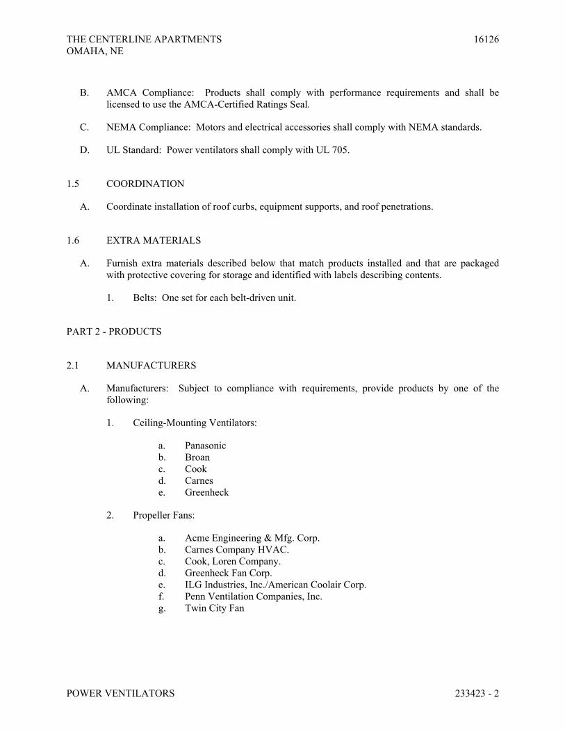
THE CENTERLINE APARTMENTS 16126
OMAHA, NE
POWER VENTILATORS 233423 - 2
B. AMCA Compliance: Products shall comply with performance requirements and shall be
licensed to use the AMCA-Certified Ratings Seal.
C. NEMA Compliance: Motors and electrical accessories shall comply with NEMA standards.
D. UL Standard: Power ventilators shall comply with UL 705.
1.5 COORDINATION
A. Coordinate installation of roof curbs, equipment supports, and roof penetrations.
1.6 EXTRA MATERIALS
A. Furnish extra materials described below that match products installed and that are packaged
with protective covering for storage and identified with labels describing contents.
1. Belts: One set for each belt-driven unit.
PART 2 - PRODUCTS
2.1 MANUFACTURERS
A. Manufacturers: Subject to compliance with requirements, provide products by one of the
following:
1. Ceiling-Mounting Ventilators:
a. Panasonic
b. Broan
c. Cook
d. Carnes
e. Greenheck
2. Propeller Fans:
a. Acme Engineering & Mfg. Corp.
b. Carnes Company HVAC.
c. Cook, Loren Company.
d. Greenheck Fan Corp.
e. ILG Industries, Inc./American Coolair Corp.
f. Penn Ventilation Companies, Inc.
g. Twin City Fan

THE CENTERLINE APARTMENTS 16126
OMAHA, NE
POWER VENTILATORS 233423 - 3
2.2 CEILING-MOUNTING VENTILATORS
A. Description: Centrifugal fans designed for installing in ceiling or wall or for concealed in-line
applications.
B. Housing: Steel, lined with acoustical insulation.
C. Fan Wheel: Centrifugal wheels directly mounted on motor shaft. Fan shrouds, motor, and fan
wheel shall be removable for service.
D. Grille: Plastic, louvered grille with flange on intake and thumbscrew attachment to fan housing.
E. Electrical Requirements: Junction box for electrical connection on housing and receptacle for
motor plug-in.
F. Accessories:
1. Variable-Speed Controller: Solid-state control to reduce speed from 100 percent to less
than 50 percent.
2. Ceiling Radiation Damper: Fire-rated assembly with ceramic blanket, stainless-steel
springs, and fusible link.
3. Isolation: Rubber-in-shear vibration isolators.
4. Manufacturer's standard roof jack or wall cap, and transition fittings.
G. Controls: As indicated on plans; one of the following.
1. Wall switch with humidity sensor
2. Continuous operation
3. Time Clock
2.3 PROPELLER FANS
A. Description: Belt-driven or direct-driven propeller fans consisting of fan blades, hub, housing,
orifice ring, motor, drive assembly, and accessories.
B. Housing: Galvanized steel sheet with flanged edges and integral orifice ring with baked-enamel
finish coat applied after assembly.
C. Steel Fan Wheels: Formed-steel blades riveted to heavy-gage steel spider bolted to cast-iron
hub.
D. Fan Wheel: Replaceable, aluminum, airfoil blades fastened to cast-aluminum hub; factory set
pitch angle of blades.
E. Belt-Driven Drive Assembly: Resiliently mounted to housing, statically and dynamically
balanced and selected for continuous operation at maximum rated fan speed and motor
horsepower, with final alignment and belt adjustment made after installation.
1. Service Factor Based on Fan Motor: 1.4.

THE CENTERLINE APARTMENTS 16126
OMAHA, NE
POWER VENTILATORS 233423 - 4
2. Fan Shaft: Turned, ground, and polished steel; keyed to wheel hub.
3. Shaft Bearings: Permanently lubricated, permanently sealed, self-aligning ball bearings.
a. Ball-Bearing Rating Life: ABMA 9, L10 of 100,000 hours.
4. Pulleys: Cast iron with split, tapered bushing; dynamically balanced at factory.
5. Motor Pulleys: Adjustable pitch for use with motors through 5 hp; fixed pitch for use
with motors larger than 5 hp. Select pulley so pitch adjustment is at the middle of
adjustment range at fan design conditions.
6. Belts: Oil resistant, nonsparking, and nonstatic; matched sets for multiple belt drives.
7. Belt Guards: Fabricate of steel for motors mounted on outside of fan cabinet.
F. Accessories:
1. Gravity Shutters: Aluminum blades in aluminum frame; interlocked blades with nylon
bearings.
2. Motor-Side Back Guard: Galvanized steel, complying with OSHA specifications,
removable for maintenance.
3. Wall Sleeve: Galvanized steel to match fan and accessory size.
4. Weathershield Hood: Galvanized steel to match fan and accessory size.
5. Weathershield Front Guard: Galvanized steel with expanded metal screen.
6. Variable-Speed Controller: Solid-state control to reduce speed from 100 percent to less
than 50 percent.
7. Disconnect Switch: Nonfusible type, with thermal-overload protection mounted inside
fan housing, factory wired through an internal aluminum conduit.
2.4 MOTORS
A. Comply with requirements in Division 23 Section "Basic Materials and Methods for HVAC."
B. Enclosure Type: Guarded dripproof.
2.5 SOURCE QUALITY CONTROL
A. Sound-Power Level Ratings: Comply with AMCA 301, "Methods for Calculating Fan Sound
Ratings from Laboratory Test Data." Factory test fans according to AMCA 300, "Reverberant
Room Method for Sound Testing of Fans." Label fans with the AMCA-Certified Ratings Seal.
B. Fan Performance Ratings: Establish flow rate, pressure, power, air density, speed of rotation,
and efficiency by factory tests and ratings according to AMCA 210, "Laboratory Methods of
Testing Fans for Rating."

THE CENTERLINE APARTMENTS 16126
OMAHA, NE
POWER VENTILATORS 233423 - 5
PART 3 - EXECUTION
3.1 INSTALLATION
A. Install power ventilators level and plumb.
B. Secure roof-mounting fans to roof curbs with cadmium-plated hardware.
C. Ceiling Units: Suspend units from structure; use vibration isolating hangers.
D. Support suspended units from structure using threaded steel rods and vibration isolators.
E. Install units with clearances for service and maintenance.
3.2 CONNECTIONS
A. Duct installation and connection requirements are specified in other Division 23 Sections.
Drawings indicate general arrangement of ducts and duct accessories. Make final duct
connections with flexible connectors.
B. Install ducts adjacent to power ventilators to allow service and maintenance.
3.3 FIELD QUALITY CONTROL
A. Equipment Startup Checks:
1. Verify that shipping, blocking, and bracing are removed.
2. Verify that unit is secure on mountings and supporting devices and that connections to
ducts and electrical components are complete. Verify that proper thermal-overload
protection is installed in motors, starters, and disconnect switches.
3. Verify that cleaning and adjusting are complete.
4. Disconnect fan drive from motor, verify proper motor rotation direction, and verify fan
wheel free rotation and smooth bearing operation. Reconnect fan drive system, align and
adjust belts, and install belt guards.
5. Verify lubrication for bearings and other moving parts.
6. Verify that manual and automatic volume control and fire and smoke dampers in
connected ductwork systems are in fully open position.
7. Disable automatic temperature-control operators.
B. Starting Procedures:
1. Energize motor and adjust fan to indicated rpm.
2. Measure and record motor voltage and amperage.
C. Operational Test: After electrical circuitry has been energized, start units to confirm proper
motor rotation and unit operation. Remove malfunctioning units, replace with new units, and
retest.

THE CENTERLINE APARTMENTS 16126
OMAHA, NE
POWER VENTILATORS 233423 - 6
D. Test and adjust controls and safeties. Replace damaged and malfunctioning controls and
equipment.
E. Refer to Division 23 Section "Testing, Adjusting, and Balancing" for testing, adjusting, and
balancing procedures.
F. Replace fan and motor pulleys as required to achieve design airflow.
G. Repair or replace malfunctioning units. Retest as specified above after repairs or replacements
are made.
3.4 ADJUSTING
A. Adjust damper linkages for proper damper operation.
B. Adjust belt tension.
C. Lubricate bearings.
3.5 CLEANING
A. On completion of installation, internally clean fans according to manufacturer's written
instructions. Remove foreign material and construction debris. Vacuum fan wheel and cabinet.
B. After completing system installation, including outlet fitting and devices, inspect exposed
finish. Remove burrs, dirt, and construction debris and repair damaged finishes.
3.6 DEMONSTRATION
A. Engage a factory-authorized service representative to train Owner's maintenance personnel to
adjust, operate, and maintain power ventilators.
1. Train Owner's maintenance personnel on procedures and schedules for starting and
stopping, troubleshooting, servicing, and maintaining equipment and schedules.
2. Review data in maintenance manuals.
3. Schedule training with Owner, through Architect, with at least seven days' advance
notice.
END OF SECTION 233423

THE CENTERLINE APARTMENTS 16126
OMAHA, NE
GAS-FIRED UNIT HEATERS 235533 - 1
SECTION 235533 - GAS-FIRED UNIT HEATERS
PART 1 - GENERAL
1.1 RELATED DOCUMENTS
A. Drawings and general provisions of the Contract, including General and Supplementary
Conditions and Division 01 Specification Sections, apply to this Section.
1.2 SUMMARY
A. Section includes gas-fired unit heaters.
1.3 ACTION SUBMITTALS
A. Product Data: For each type of gas-fired unit heater.
1. Include rated capacities, operating characteristics, and accessories.
B. Shop Drawings: For gas-fired unit heaters. Include plans, elevations, sections, and attachment
details.
C. Sample Warranty: For special warranty.
D. Operation and Maintenance Data: For gas-fired unit heaters to include in emergency, operation,
and maintenance manuals.
1.4 MAINTENANCE MATERIAL SUBMITTALS
A. Furnish extra materials that match products installed and that are packaged with protective
covering for storage and identified with labels describing contents.
1. Fan Belts: One for each belt-driven fan size.
1.5 QUALITY ASSURANCE
A. ASHRAE/IES 90.1 Compliance: Applicable requirements in ASHRAE/IES 90.1, Section 6 -
"Heating, Ventilating, and Air-Conditioning."

THE CENTERLINE APARTMENTS 16126
OMAHA, NE
GAS-FIRED UNIT HEATERS 235533 - 2
1.6 WARRANTY
A. Special Warranty: Manufacturer agrees to repair or replace heat exchanger of gas-fired unit
heater that fails in materials or workmanship within specified warranty period.
1. Warranty Period: Five years from date of Substantial Completion.
PART 2 - PRODUCTS
2.1 MANUFACTURERS
A. Manufacturers: Subject to compliance with requirements, provide products by one of the
following:
1. Lennox International, Inc.
2. Modine Manufacturing Company.
3. Reznor/Thomas & Betts Corporation.
4. Sterling HVAC Products; Div. of Mestek Technology Inc.
5. Trane; a brand of Ingersoll Rand.
2.2 PERFORMANCE REQUIREMENTS
A. Electrical Components, Devices, and Accessories: Listed and labeled as defined in NFPA 70, by
a qualified testing agency, and marked for intended location and application.
2.3 MANUFACTURED UNITS
A. Description: Factory assembled, piped, and wired, and complying with ANSI Z83.8/CSA 2.6.
B. Gas Type: Design burner for natural gas having characteristics same as those of gas available at
Project site.
C. Type of Venting: Indoor, separated combustion, power vented.
D. Housing: Steel, with integral draft hood and inserts for suspension mounting rods.
1. External Casings and Cabinets: Baked enamel over corrosion-resistant-treated surface.
2. Discharge Louvers: Independently adjustable, horizontal blades.
E. Accessories:
1. Four-point suspension kit.
2. Power Venter: Centrifugal aluminized-steel fan, with stainless-steel shaft; 120-V ac
motor.

THE CENTERLINE APARTMENTS 16126
OMAHA, NE
GAS-FIRED UNIT HEATERS 235533 - 3
3. Concentric, Terminal Vent Assembly: Combined combustion-air inlet and power-vent
outlet with wall or roof caps. Include adapter assembly for connection to inlet and outlet
pipes, and flashing for wall or roof penetration.
F. Heat Exchanger: Aluminized steel.
G. Burner Material: Aluminized steel with stainless-steel inserts.
H. Propeller Unit Fan:
1. Formed-steel or Aluminum propeller blades riveted to heavy-gage steel spider bolted to
cast-iron hub, dynamically balanced, and resiliently mounted.
2. Fan-Blade Guard: Galvanized steel, complying with OSHA specifications, removable for
maintenance.
I. Centrifugal Unit Fan:
1. Steel, centrifugal fan dynamically balanced and resiliently mounted.
2. Belt-Driven Drive Assembly:
a. Resiliently mounted to housing, with the following features:
1) Fan Shaft: Turned, ground, and polished steel; keyed to wheel hub.
2) Shaft Bearings: Permanently lubricated, permanently sealed, self-
aligning ball bearings.
3) Pulleys: Cast-iron, adjustable-pitch motor pulley.
J. Motors:
1. Comply with NEMA designation, temperature rating, service factor, and efficiency
requirements for motors specified in Section 230513 "Common Motor Requirements for
HVAC Equipment."
2. Enclosure Materials: Rolled steel.
3. Efficiency: Premium efficient.
K. Controls: Regulated redundant gas valve containing pilot solenoid valve, electric gas valve,
pilot filter, pressure regulator, pilot shutoff, and manual shutoff all in one body.
1. Gas Control Valve: Single stage.
2. Ignition: Electronically controlled electric spark with flame sensor.
3. Fan Thermal Switch: Operates fan on heat-exchanger temperature.
4. Vent Flow Verification: Flame rollout switch.
5. Control transformer.
6. High Limit: Thermal switch or fuse to stop burner.
7. Thermostat: Devices and wiring are specified in Section 230900 "Instrumentation and
Control for HVAC."
8. Wall-Mounted Thermostat:
a. Single stage.
b. Fan on-off-automatic switch.

THE CENTERLINE APARTMENTS 16126
OMAHA, NE
GAS-FIRED UNIT HEATERS 235533 - 4
c. 24-V ac.
d. 50 to 90 deg F operating range.
L. Electrical Connection: Factory wire motors and controls for a single electrical connection.
PART 3 - EXECUTION
3.1 INSTALLATION
A. Install and connect gas-fired unit heaters and associated gas and vent features and systems
according to NFPA 54, applicable local codes and regulations, and manufacturer's written
instructions.
3.2 EQUIPMENT MOUNTING
A. Suspended Units: Suspend from substrate using threaded rods, spring hangers, and building
attachments. Secure rods to unit hanger attachments. Adjust hangers so unit is level and plumb.
3.3 CONNECTIONS
A. Piping installation requirements are specified in other Sections. Drawings indicate general
arrangement of piping, fittings, and specialties.
B. Where installing piping adjacent to gas-fired unit heater, allow space for service and
maintenance.
C. Gas Piping: Comply with Section 231123 "Facility Natural-Gas Piping." Connect gas piping to
gas train inlet; provide union with enough clearance for burner removal and service.
D. Vent Connections: Comply with Section 235100 "Breechings, Chimneys, and Stacks."
E. Ground equipment according to Section 260526 "Grounding and Bonding for Electrical
Systems."
F. Connect wiring according to Section 260519 "Low-Voltage Electrical Power Conductors and
Cables."
3.4 FIELD QUALITY CONTROL
A. Manufacturer's Field Service: Engage a factory-authorized service representative to test and
inspect components, assemblies, and equipment installations, including connections.
B. Perform the following tests and inspections:

THE CENTERLINE APARTMENTS 16126
OMAHA, NE
GAS-FIRED UNIT HEATERS 235533 - 5
1. Test and adjust controls and safeties. Replace damaged and malfunctioning controls and
equipment.
2. Verify bearing lubrication.
3. Verify proper motor rotation.
C. Gas-fired unit heater will be considered defective if it does not pass tests and inspections.
D. Prepare test and inspection reports.
3.5 ADJUSTING
A. Adjust initial temperature and humidity set points.
B. Adjust burner and other unit components for optimum heating performance and efficiency.
3.6 DEMONSTRATION
A. Train Owner's maintenance personnel to adjust, operate, and maintain gas-fired unit heaters.
END OF SECTION 235533

THE CENTERLINE APARTMENTS 16126
OMAHA, NE
AIR TO AIR HEAT PUMPS 236200 - 1
SECTION 236200 - AIR-TO-AIR HEAT PUMPS
PART 1 - GENERAL
1.1 RELATED DOCUMENTS
A. Drawings and general provisions of the Contract, including General and Supplementary
Conditions and other Division 1 Specification Sections, apply to this Section.
1.2 SUMMARY
A. This Section includes air-to-air heat pumps units; 1 to 5 tons.
1.3 SUBMITTALS
A. Product Data: Include rated capacities; shipping, installed, and operating weights; dimensions;
required clearances; methods for assembling components; furnished specialties; accessories;
and installation and startup instructions for each model indicated.
B. Wiring Diagrams: Detail wiring for power, signal, and control systems and differentiate
between manufacturer-installed and field-installed wiring.
C. Maintenance Data: For each condensing unit to include in the maintenance manuals. Include a
parts list for each condensing unit, control, and accessory; troubleshooting maintenance guide;
and servicing and preventive maintenance procedures and schedule.
D. Warranties: Special warranties specified in this Section.
E. See “Submittal Schedule” located at the end of Section 230100 – General Mechanical
Requirements.
1.4 QUALITY ASSURANCE
A. Listing and Labeling: Provide electrically operated equipment specified in this Section that is
listed and labeled as defined in NFPA 70, Article 100.
B. Comply with NFPA 70.
C. Comply with UL 303, "Refrigeration and Air-Conditioning Condensing and Compressor Units."
1.5 COORDINATION
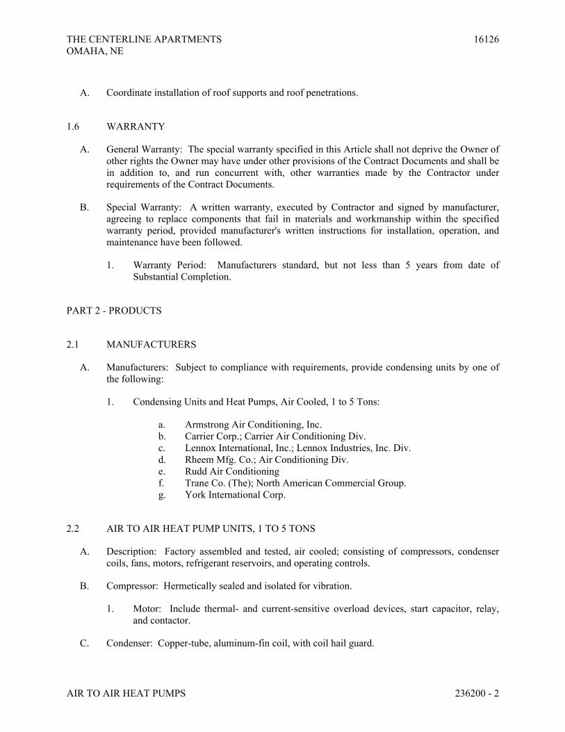
THE CENTERLINE APARTMENTS 16126
OMAHA, NE
AIR TO AIR HEAT PUMPS 236200 - 2
A. Coordinate installation of roof supports and roof penetrations.
1.6 WARRANTY
A. General Warranty: The special warranty specified in this Article shall not deprive the Owner of
other rights the Owner may have under other provisions of the Contract Documents and shall be
in addition to, and run concurrent with, other warranties made by the Contractor under
requirements of the Contract Documents.
B. Special Warranty: A written warranty, executed by Contractor and signed by manufacturer,
agreeing to replace components that fail in materials and workmanship within the specified
warranty period, provided manufacturer's written instructions for installation, operation, and
maintenance have been followed.
1. Warranty Period: Manufacturers standard, but not less than 5 years from date of
Substantial Completion.
PART 2 - PRODUCTS
2.1 MANUFACTURERS
A. Manufacturers: Subject to compliance with requirements, provide condensing units by one of
the following:
1. Condensing Units and Heat Pumps, Air Cooled, 1 to 5 Tons:
a. Armstrong Air Conditioning, Inc.
b. Carrier Corp.; Carrier Air Conditioning Div.
c. Lennox International, Inc.; Lennox Industries, Inc. Div.
d. Rheem Mfg. Co.; Air Conditioning Div.
e. Rudd Air Conditioning
f. Trane Co. (The); North American Commercial Group.
g. York International Corp.
2.2 AIR TO AIR HEAT PUMP UNITS, 1 TO 5 TONS
A. Description: Factory assembled and tested, air cooled; consisting of compressors, condenser
coils, fans, motors, refrigerant reservoirs, and operating controls.
B. Compressor: Hermetically sealed and isolated for vibration.
1. Motor: Include thermal- and current-sensitive overload devices, start capacitor, relay,
and contactor.
C. Condenser: Copper-tube, aluminum-fin coil, with coil hail guard.

THE CENTERLINE APARTMENTS 16126
OMAHA, NE
AIR TO AIR HEAT PUMPS 236200 - 3
D. Condenser Fan: Direct-drive, aluminum propeller fan; with permanently lubricated fan motor
with thermal-overload protection.
E. Accessories include the following:
1. Low ambient kit to permit cooling operation down to temperature scheduled on drawings.
2. Crankcase heater.
3. Automatic reset timer to prevent compressor rapid cycle.
F. Refrigerant piping: Annealed-copper suction and liquid lines factory cleaned, dried, pressurized,
and sealed, expansion device, service valves, drier, sight glass.
G. Casing: Steel, finished with baked enamel; with removable panels for access to controls, weep
holes for water drainage, and mounting holes in base. Mount service valves, fittings, and gage
ports on exterior of casing.
H. Motor: NEMA MG 1, general purpose, continuous duty, Design B, single point connection,
motor overload protection.
I. Reversing Valve: Reverse direction of refrigerant flow in air-to-air heat pump to change from
heating mode to cooling mode.
2.3 SOURCE QUALITY CONTROL
A. Verification of Performance: Rate condensing units according to ARI 210/240.
B. Test and inspect shell and tube condensers according to ASME Boiler and Pressure Vessel
Code: Section VIII, "Pressure Vessels," Division 1.
C. Testing Requirements: Factory test sound-power-level ratings according to ARI 270.
PART 3 - EXECUTION
3.1 INSTALLATION
A. Install condensing units or heat pumps according to manufacturer's written instructions.
B. Install units level and plumb, firmly anchored in locations indicated; maintain manufacturer's
recommended clearances.
C. Install ground mounted units on reinforce concrete base. Coordinate site of base with General
Contractor.
D. Install roof-mounted units on heat pump supports. See plans for details.
E. Connect refrigerant piping to air-cooled condensing units or air-to-air heat pumps; maintain
required access to unit. Install furnished field-mounted accessories.

THE CENTERLINE APARTMENTS 16126
OMAHA, NE
AIR TO AIR HEAT PUMPS 236200 - 4
3.2 FIELD QUALITY CONTROL
A. Leak Test: After installation, charge systems with refrigerant and oil and test for leaks. Repair
leaks and replace lost refrigerant and oil.
B. Operational Test: After electrical circuitry has been energized, start units to confirm proper
operation, product capability, and compliance with requirements.
1. Test and adjust controls and safeties. Replace damaged and malfunctioning controls and
equipment.
C. Remove and replace malfunctioning units with new units and retest.
3.3 CLEANING
A. After completing system installation, including outlet fittings and devices, inspect exposed
finish. Clean units to remove dirt and construction debris and repair damaged finishes.
3.4 DEMONSTRATION
A. Startup Services: Engage a factory-authorized service representative to train Owner's
maintenance personnel as specified below:
1. Train Owner's maintenance personnel on procedures and schedules related to startup and
shutdown, troubleshooting, servicing, and preventive maintenance.
2. Review data in the maintenance manuals.
3.5 REBATES
A. The Electric utility company may offer a rebate for the installation of heat pumps. The
mechanical contractor shall receive the rebates for the project. The mechanical contractor shall
adjust their bid price accordingly due to any applicable rebates. The contractor shall be
responsible for filing all paperwork and coordinating all inspections necessary for receipt of the
rebates.
END OF SECTION 236200
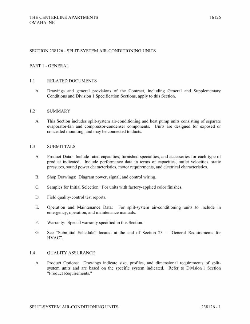
THE CENTERLINE APARTMENTS 16126
OMAHA, NE
SPLIT-SYSTEM AIR-CONDITIONING UNITS 238126 - 1
SECTION 238126 - SPLIT-SYSTEM AIR-CONDITIONING UNITS
PART 1 - GENERAL
1.1 RELATED DOCUMENTS
A. Drawings and general provisions of the Contract, including General and Supplementary
Conditions and Division 1 Specification Sections, apply to this Section.
1.2 SUMMARY
A. This Section includes split-system air-conditioning and heat pump units consisting of separate
evaporator-fan and compressor-condenser components. Units are designed for exposed or
concealed mounting, and may be connected to ducts.
1.3 SUBMITTALS
A. Product Data: Include rated capacities, furnished specialties, and accessories for each type of
product indicated. Include performance data in terms of capacities, outlet velocities, static
pressures, sound power characteristics, motor requirements, and electrical characteristics.
B. Shop Drawings: Diagram power, signal, and control wiring.
C. Samples for Initial Selection: For units with factory-applied color finishes.
D. Field quality-control test reports.
E. Operation and Maintenance Data: For split-system air-conditioning units to include in
emergency, operation, and maintenance manuals.
F. Warranty: Special warranty specified in this Section.
G. See “Submittal Schedule” located at the end of Section 23 – “General Requirements for
HVAC”.
1.4 QUALITY ASSURANCE
A. Product Options: Drawings indicate size, profiles, and dimensional requirements of split-
system units and are based on the specific system indicated. Refer to Division 1 Section
"Product Requirements."

THE CENTERLINE APARTMENTS 16126
OMAHA, NE
SPLIT-SYSTEM AIR-CONDITIONING UNITS 238126 - 2
B. Electrical Components, Devices, and Accessories: Listed and labeled as defined in NFPA 70,
Article 100, by a testing agency acceptable to authorities having jurisdiction, and marked for
intended use.
C. Energy-Efficiency Ratio: Equal to or greater than prescribed by ASHRAE 90.1, "Energy
Efficient Design of New Buildings except Low-Rise Residential Buildings."
D. Coefficient of Performance: Equal to or greater than prescribed by ASHRAE 90.1, "Energy
Efficient Design of New Buildings except Low-Rise Residential Buildings."
1.5 WARRANTY
A. Special Warranty: Manufacturer's standard form in which manufacturer agrees to repair or
replace components of split-system air-conditioning units that fail in materials or workmanship
within specified warranty period.
1. Warranty Period: Five years from date of Substantial Completion.
1.6 EXTRA MATERIALS
A. Furnish extra materials described below that match products installed and that are packaged
with protective covering for storage and identified with labels describing contents.
1. Filters: One set of filters for each unit.
2. Fan Belts: One set of belts for each unit.
PART 2 - PRODUCTS
2.1 MANUFACTURERS
A. Manufacturers: Subject to compliance with requirements, provide products by one of the
following:
1. Carrier
2. Daikin
3. Mitsubishi
4. Trane
5. Fujitsu
6. Toshiba
2.2 EVAPORATOR-FAN COMPONENTS
A. Wall Mounted Cabinet: Enameled steel with removable panels on front and ends in color
selected by Architect, and discharge drain pans with drain connection

THE CENTERLINE APARTMENTS 16126
OMAHA, NE
SPLIT-SYSTEM AIR-CONDITIONING UNITS 238126 - 3
B. Refrigerant Coil: Copper tube, with mechanically bonded aluminum fins, complying with
ARI 210/240, and with thermal-expansion valve.
C. Fan: Forward-curved, double-width wheel of galvanized steel; directly connected to motor.
D. Fan Motors: Multitapped, multispeed with internal thermal protection and permanent
lubrication.
E. Disposable Filters: 1 inch thick, in fiberboard frames.
F. Wiring Terminations: Connect motor to chassis wiring with plug connection.
2.3 AIR-COOLED, COMPRESSOR-CONDENSER COMPONENTS
A. Casing: Steel, finished with baked enamel in color selected by Architect, with removable
panels for access to controls, weep holes for water drainage, and mounting holes in base.
Provide brass service valves, fittings, and gage ports on exterior of casing.
B. Compressor: Hermetically sealed with crankcase heater and mounted on vibration isolation.
Compressor motor shall have thermal- and current-sensitive overload devices, start capacitor,
relay, and contactor.
1. Compressor Type: Scroll.
2. Two-speed compressor motor with manual-reset high-pressure switch and automatic-
reset low-pressure switch.
3. Refrigerant Charge: R-410A
C. Refrigerant Coil: Copper tube, with mechanically bonded aluminum fins, complying with
ARI 210/240, and with liquid subcooler.
D. Fan: Aluminum-propeller type, directly connected to motor.
E. Motor: Permanently lubricated, with integral thermal-overload protection.
F. Low Ambient Kit: Permits operation down to -20° F.
2.4 ACCESSORIES
A. Thermostat: Low voltage with subbase to control compressor and evaporator fan.
B. Thermostat: Wired wall mounted controller to remotely control compressor and evaporator fan,
with the following features:
1. Compressor time delay.
2. 24-hour time control of system stop and start.
3. Liquid-crystal display indicating temperature, set-point temperature, time setting,
operating mode, and fan speed.
4. Fan-speed selection, including auto setting.

THE CENTERLINE APARTMENTS 16126
OMAHA, NE
SPLIT-SYSTEM AIR-CONDITIONING UNITS 238126 - 4
C. Automatic-reset timer to prevent rapid cycling of compressor.
D. Refrigerant Line Kits: Soft-annealed copper suction and liquid lines factory cleaned, dried,
pressurized, and sealed; factory-insulated suction line with flared fittings at both ends.
PART 3 - EXECUTION
3.1 INSTALLATION
A. Install units level and plumb.
B. Install evaporator-fan components using manufacturer's standard mounting devices securely
fastened to building structure.
C. Install ground-mounting, compressor-condenser components on 4-inch-thick, reinforced
concrete base; 4 inches larger on each side than unit.
D. Install roof-mounting compressor-condenser components on wood sleepers.
E. Install refrigerant piping per manufacturer’s recommendations. Install piping to allow access to
unit.
3.2 CONNECTIONS
A. Drawings indicate general arrangement of piping, fittings, and specialties.
B. Install piping adjacent to unit to allow service and maintenance.
C. Duct Connections: Drawings indicate the general arrangement of ducts. Connect ducts to split-
system air-conditioning units with flexible duct connectors.
3.3 STARTUP SERVICE
A. Engage a factory-authorized service representative to perform startup service. Complete
installation and startup checks according to manufacturer's written instructions.
3.4 DEMONSTRATION
A. Engage a factory-authorized service representative to train Owner's maintenance personnel to
adjust, operate, and maintain units. Refer to Division 1 Sections.
END OF SECTION 238126
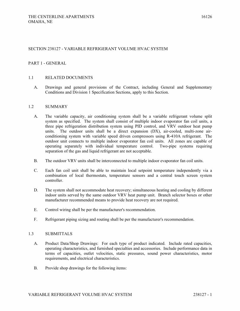
THE CENTERLINE APARTMENTS 16126
OMAHA, NE
VARIABLE REFRIGERANT VOLUME HVAC SYSTEM 238127 - 1
SECTION 238127 - VARIABLE REFRIGERANT VOLUME HVAC SYSTEM
PART 1 - GENERAL
1.1 RELATED DOCUMENTS
A. Drawings and general provisions of the Contract, including General and Supplementary
Conditions and Division 1 Specification Sections, apply to this Section.
1.2 SUMMARY
A. The variable capacity, air conditioning system shall be a variable refrigerant volume split
system as specified. The system shall consist of multiple indoor evaporator fan coil units, a
three pipe refrigeration distribution system using PID control, and VRV outdoor heat pump
units. The outdoor units shall be a direct expansion (DX), air-cooled, multi-zone air-
conditioning system with variable speed driven compressors using R-410A refrigerant. The
outdoor unit connects to multiple indoor evaporator fan coil units. All zones are capable of
operating separately with individual temperature control. Two-pipe systems requiring
separation of the gas and liquid refrigerant are not acceptable.
B. The outdoor VRV units shall be interconnected to multiple indoor evaporator fan coil units.
C. Each fan coil unit shall be able to maintain local setpoint temperature independently via a
combination of local thermostats, temperature sensors and a central touch screen system
controller.
D. The system shall not accommodate heat recovery; simultaneous heating and cooling by different
indoor units served by the same outdoor VRV heat pump unit. Branch selector boxes or other
manufacturer recommended means to provide heat recovery are not required.
E. Control wiring shall be per the manufacturer's recommendation.
F. Refrigerant piping sizing and routing shall be per the manufacturer's recommendation.
1.3 SUBMITTALS
A. Product Data/Shop Drawings: For each type of product indicated. Include rated capacities,
operating characteristics, and furnished specialties and accessories. Include performance data in
terms of capacities, outlet velocities, static pressures, sound power characteristics, motor
requirements, and electrical characteristics.
B. Provide shop drawings for the following items:

THE CENTERLINE APARTMENTS 16126
OMAHA, NE
VARIABLE REFRIGERANT VOLUME HVAC SYSTEM 238127 - 2
1. Detail equipment assemblies and indicate dimensions, weights, loads, required
clearances, method of field assembly, components, and location and size of each field
connection.
2. Wiring Diagrams: For power, signal, and control wiring.
3. Outdoor VRV Units (include capacities, electrical connection data, etc.)
4. Indoor VRV Units (include rated capacities, airflow, static pressure, installation
configurations, required clearance, electrical connection data, etc.)
5. All required accessory equipment
6. System schematics showing refrigerant piping system
7. System schematics showing control wiring requirements
C. Operation and Maintenance Data: For all HVAC system equipment to include in emergency,
operation, and maintenance manuals.
D. Warranty: Sample of special warranty.
1.4 QUALITY ASSURANCE
A. Electrical Components, Devices, and Accessories: Listed and labeled as defined in NFPA 70,
by a qualified testing agency, and marked for intended location and application.
B. The units shall be listed by Electrical Laboratories (ETL) and bear the cETL label.
C. All wiring shall be in accordance with the National Electric Code (NEC).
D. The system will be produced in an ISO 9001 and ISO 14001 facility, which are standards set by
the International Standard Organization (ISO). The system shall be factory tested for safety and
function.
E. The outdoor units will be factory charged with R-410A.
F. ASHRAE Compliance:
1. Fabricate and label refrigeration system to comply with ASHRAE 15, "Safety Standard
for Refrigeration Systems."
2. ASHRAE Compliance: Applicable requirements in ASHRAE 62.1-2004, Section 4 -
"Outdoor Air Quality," Section 5 - "Systems and Equipment," Section 6 - " Procedures,"
and Section 7 - "Construction and System Start-Up."
G. ASHRAE/IESNA Compliance: Applicable requirements in ASHRAE/IESNA 90.1-2004.
1.5 COORDINATION
A. Coordinate sizes and locations of equipment with actual equipment provided, building structure,
ceilings, architectural features, other mechanical and electrical equipment.
B. Ceiling space may be limited. Acceptable alternate manufacturers must coordinate with space
available.
THE CENTERLINE APARTMENTS 16126
OMAHA, NE
VARIABLE REFRIGERANT VOLUME HVAC SYSTEM 238127 - 3
1.6 WARRANTY
A. Special Warranty: Manufacturer's standard form in which manufacturer agrees to repair or
replace any components of the HVAC system that fails in materials or workmanship within
specified warranty period.
1. Warranty Period:
a. For Compressor: Five year(s) from date of Substantial Completion.
b. For other equipment: One year from date of Substantial Completion.
c. For Parts: One year from date of Substantial Completion.
d. For Labor: One year from date of Substantial Completion.
B. Installation Requirements
1. The system must be installed by a factory trained contractor/dealer. The bidders shall be
required to submit training certification proof with bid documents. The mechanical
contractor’s installation price shall be based on the systems installation requirements.
The mechanical contractor bids with complete knowledge of the HVAC system
requirements. Untrained contractors who wish to bid this project may contact local
manufacturer’s representative to coordinate. Training must be completed prior to
installation.
1.7 EXTRA MATERIALS
A. Furnish extra materials that match products installed and that are packaged with protective
covering for storage and identified with labels describing contents.
1. Filters: One set for each indoor fan coil unit.
PART 2 - PRODUCTS
2.1 MANUFACTURERS
A. Manufacturers: Subject to compliance with requirements, provide products by one of the
following:
1. Basis of Design: Mitsubishi
2. Alternate Manufacturers:
a. Daikin
b. Sanyo
c. LG
d. Trane

THE CENTERLINE APARTMENTS 16126
OMAHA, NE
VARIABLE REFRIGERANT VOLUME HVAC SYSTEM 238127 - 4
B. Alternate Manufacturer: Alternate equipment supplier shall provide a complete submittal
indicating any changes in electrical requirements, refrigerant pipe design and routing, or control
systems wiring or requirements different than the base specified system.
2.2 OUTDOOR UNITS
A. General:
1. The outdoor unit shall be factory assembled and pre-wired with all necessary
electronic and refrigerant controls. The refrigeration circuit of the condensing
unit shall consist of scroll compressors, motors, fans, condenser coil, electronic
expansion valves, solenoid valves, 4-way valve, distribution headers, capillaries,
filters, shut off valves, oil separators, service ports and refrigerant regulator.
High/low pressure gas line, liquid and suction lines must be individually
insulated between the outdoor and indoor units.
2. Each outdoor system shall be able to support the connection of multiple indoor
units as indicated on the plans.
3. The system will automatically restart operation after a power failure without loss
of system control settings.
4. The following safety devices shall be included on the condensing unit; high
pressure switch, control circuit fuses, crankcase heaters, fusible plug, high
pressure switch, overload relay, inverter overload protector, thermal protectors
for compressor and fan motors, over current protection for the inverter and anti-
recycling timers.
5. To ensure the liquid refrigerant does not flash when supplying the fan coil units,
the circuit shall be provided with a sub-cooling feature.
6. Oil recovery cycle shall be automatic; occurring 2 hours after start of operation
and then every 8 hours of operation.
7. The outdoor unit shall be capable of heating operation at 0°F dry bulb ambient
temperature.
8. The system shall continue to provide heat to the indoor units in heating operation
while in the defrost mode.
B. Unit Cabinet:
1. The outdoor unit shall be completely weatherproof and corrosion resistant. The
unit shall be constructed from rust-proofed mild steel panels coated with a baked
enamel finish.
C. Fan:
1. The condensing unit shall consist of one or more propeller type, direct-drive fan
motors with variable speed operation .
2. The fan shall be a vertical discharge configuration with.
3. Nominal sound pressure levels shall be no more than 63 dB(A).
4. The fan motor shall have permanently lubricated bearings.
5. The fan motor shall be provided with a fan guard.

THE CENTERLINE APARTMENTS 16126
OMAHA, NE
VARIABLE REFRIGERANT VOLUME HVAC SYSTEM 238127 - 5
6. Night setback control of the fan motor for low noise operation by way of
automatically limiting the maximum speed shall be provided.
D. Condenser Coil:
1. The condenser coil shall be manufactured from copper tubes expanded into
aluminum fins.
E. Compressor:
1. Provide hermetically sealed inverter scroll compressors, variable speed
controlled to follow the variations in total cooling and heating load.
2. Compressors shall be spring mounted.
3. Each compressor shall be equipped with a crankcase heater, high pressure safety
switch, internal thermal overload protector, and oil separators as required.
F. Control: The outdoor unit shall have controls provided by the manufacturer to perform input
functions necessary to operate the system. Controls shall be installed by the mechanical
contractor.
2.3 VRV INDOOR UNITS
A. General: Indoor units shall operate with R-410A refrigerant and shall be equipped
with an electronic expansion valve and computerized PID controls.
B. General
1. DX cooling using R-410A refrigerant
2. Factory assembled and tested with factory wiring, piping, expansion valve,
control circuit board, and fan motor.
3. Direct drive fan motor
4. Condensate pan and factory condensate pump where indicated on plans.
C. Filter: Manufacturer's standard washable filter in ceiling cartridge units. 1" pleated
disposable filters with ducted units.
D. Coil: Copper direct expansion refrigerant coil.
E. Control: Manufacturer's standard microprocessor based controls.
F. Provide branch selector boxes for VRV systems requiring heat recover; simultaneous
heating and cooling for indoor units served by the same outdoor unit.
G. Accessories:
1. Fresh air intake and supply air duct connections where indicated on plans.
2. Remote wall mounted temperature sensor or thermostat where indicated on plans.
3. Condensate pumps where required and not integral.

THE CENTERLINE APARTMENTS 16126
OMAHA, NE
VARIABLE REFRIGERANT VOLUME HVAC SYSTEM 238127 - 6
PART 3 - EXECUTION
3.1 INSTALLATION
A. Install units level and plumb.
B. Install evaporator-fan components using manufacturer's standard mounting devices securely
fastened to building structure.
C. Install roof-mounted, outdoor equipment per support details on plans or manufacturer's
recommendations.
D. Install and connect refrigerant piping per manufacturer’s recommendations.
3.2 CONNECTIONS
A. Piping installation requirements are specified in other Division 23 Sections. Drawings indicate
general arrangement of piping, fittings, and specialties.
B. Where piping is installed adjacent to unit, allow space for access, service and maintenance of
unit.
C. Duct Connections: Duct installation requirements are specified in Division 23 Section "Metal
Ducts." Drawings indicate the general arrangement of ducts. Connect supply and return ducts
to indoor VRV units with flexible duct connectors. Flexible duct connectors are specified in
Division 23 Section "Duct Accessories."
3.3 FIELD QUALITY CONTROL
A. Manufacturer's Field Service: Engage a factory-authorized service representative to inspect,
test, and adjust components, assemblies, and equipment installations, including connections.
B. Perform tests and inspections.
1. Manufacturer's Field Service: Engage a factory-authorized service representative to
inspect components, assemblies, and equipment installations, including connections, and
to assist in testing.
C. Tests and Inspections:
1. Leak Test: After installation, charge system and test for leaks. Repair leaks and retest
until no leaks exist.
2. Operational Test: After electrical circuitry has been energized, start units to confirm
proper motor rotation and unit operation.
3. Test and adjust controls and safeties. Replace damaged and malfunctioning controls and
equipment.
THE CENTERLINE APARTMENTS 16126
OMAHA, NE
VARIABLE REFRIGERANT VOLUME HVAC SYSTEM 238127 - 7
D. Remove and replace malfunctioning units and retest as specified above.
E. Prepare test and inspection reports.
3.4 STARTUP SERVICE
A. Engage a factory-authorized service representative to perform startup service for the entire VRV
HVAC system.
B. Factory-authorized service representative shall provide full training of the VRV system to the
owner/operator.
3.5 DEMONSTRATION
A. Engage a factory-authorized service representative to train Owner's maintenance personnel to
adjust, operate, and maintain units.
END OF SECTION 238127

THE CENTERLINE APARTMENTS 16126
OMAHA, NE
FAN-COIL UNITS 238219 - 1
SECTION 238219 - FAN-COIL UNITS
PART 1 - GENERAL
1.1 RELATED DOCUMENTS
A. Drawings and general provisions of the Contract, including General and Supplementary
Conditions and Division 1 Specification Sections, apply to this Section.
1.2 SUMMARY
A. This Section includes fan-coil units and accessories.
1.3 SUBMITTALS
A. Product Data: Include specialties and accessories for each unit type and configuration.
B. Shop Drawings: Submit the following for each fan-coil unit type and configuration:
1. Plans, elevations, sections, and details.
2. Power, signal, and control wiring diagrams. Differentiate between manufacturer-installed
and field-installed wiring.
3. Equipment schedules to include rated capacities; shipping, installed, and operating
weights; furnished specialties; and accessories.
C. Field Test Reports: Written reports of tests specified in Part 3 of this Section.
D. Maintenance Data: For fan-coil units to include in maintenance manuals specified in
Division 1. Include the following:
1. Maintenance schedules and repair parts lists for motors, coils, integral controls, and
filters.
E. See Submittal Schedule located at the end of Section 230100 – General Mechanical
Requirements.
1.4 QUALITY ASSURANCE
A. Electrical Components, Devices, and Accessories: Listed and labeled as defined in NFPA 70,
Article 100, by a testing agency acceptable to authorities having jurisdiction, and marked for
intended use.
THE CENTERLINE APARTMENTS 16126
OMAHA, NE
FAN-COIL UNITS 238219 - 2
1.5 EXTRA MATERIALS
A. Furnish extra materials described below that match products installed and that are packaged
with protective covering for storage and identified with labels describing contents.
1. Fan-Coil Unit Filters: Furnish one spare filter for each filter installed.
PART 2 - PRODUCTS
2.1 MANUFACTURERS
A. Manufacturers: Subject to compliance with requirements, provide products by one of the
following:
1. Armstrong Air Conditioning, Inc.
2. Carrier Corp.; Carrier Air Conditioning Div.
3. Lennox International, Inc.; Lennox Industries, Inc. Div.
4. Rheem Mfg. Co.; Air Conditioning Div.
5. Ruud Air Conditioning.
6. Trane Co. (The); North American Commercial Group.
7. York International Corp.
2.2 CONFIGURATION
A. Wall mounted Units: An assembly, including cabinet, filter, chassis, coil, drain pan, fan, and
motor in blow-through configuration with direct-expansion cooling coil and electric heating
coil. Unit shall be wall mounted with open return configuration.
B. Multi-position Units: An assembly, including cabinet, filter, chassis, coil, drain pan, fan, and
motor in blow-through configuration with direct-expansion cooling coil and electric heating
coil. Unit shall be capable of operating in upflow or horizontal configuration.
2.3 MATERIALS
A. Chassis: Galvanized steel, with flanged edges.
B. Coil Section Insulation: 1-inch duct liner complying with ASTM C 1071 and attached with
adhesive complying with ASTM C 916.
1. Fire-Hazard Classification: Duct liner and adhesive shall have a maximum flame-spread
rating of 25 and smoke-developed rating of 50 when tested according to ASTM E 84.
C. Drain Pans: Galvanized steel, with connection for drain. Drain pan shall be insulated with
polystyrene or polyurethane insulation. Drain pan shall be formed to slope from all directions
to drain connection.
THE CENTERLINE APARTMENTS 16126
OMAHA, NE
FAN-COIL UNITS 238219 - 3
D. Cabinet: Galvanized steel, with removable front panel.
2.4 DIRECT-EXPANSION REFRIGERANT COILS
A. Evaporator Coil: Copper tubes mechanically expanded into aluminum fins. Comply with
ARI 210/240, "Unitary Air-Conditioning and Air-Source Heat Pump Equipment." Match size
with fan coil unit. Match remote heat pump unit specified in Division 23 Section "Air to Air
Heat Pumps" with type, capacity, pressure-drop ratings, restricted distributor, or expansion
valve. Include condensate drain pan with accessible drain outlet.
B. Evaporator Coil Enclosure: Steel, matching furnace and evaporator coil, with access panel and
flanges for integral mounting at or on furnace cabinet and galvanized sheet metal drain pan
coated with black asphaltic base paint.
C. Refrigerant Line Kits: Annealed-copper suction and liquid lines factory cleaned, dried,
pressurized with nitrogen, and sealed. Insulate suction line with minimum 3/8-inch- thick,
flexible elastomeric tubular insulation complying with ASTM C 534, Type I. Flared or sweat
ends compatible with coil and condensing unit connections. Provide all refrigerant accessories
required for long line set applications as required for roof top mounting. See plans and
mechanical schedules for additional information.
2.5 ELECTRIC-RESISTANCE HEATING ELEMENTS
A. Nickel-chromium heating wire, free from expansion noise and 60-Hz hum, embedded in
magnesium-oxide insulating refractory and sealed in high-mass steel or corrosion-resistant
metallic sheath with fins no closer than 0.16 inch. Element ends shall be enclosed in terminal
box. Fin surface temperature shall not exceed 550 deg F at any point during normal operation.
1. Circuit Protection and Disconnects: Provide unit mounted disconnects and circuit
breakers as indicated on mechanical schedules.
2. Wiring Terminations: Match conductor materials and sizes indicated.
2.6 FAN
A. Centrifugal, with forward-curved, double-width wheels and fan scrolls made of galvanized steel
or thermoplastic material; directly connected to or V-belt driven from motor.
2.7 FAN MOTORS
A. Motors for Direct-Drive Units: Multispeed motor with integral thermal-overload protection and
resilient mounts.
B. Wiring Terminations: Match conductor materials and sizes of connecting power circuit.
Connect motor to chassis wiring with plug connection.
THE CENTERLINE APARTMENTS 16126
OMAHA, NE
FAN-COIL UNITS 238219 - 4
2.8 ACCESSORIES
A. Filters: 1-inch- thick, throwaway filters in fiberboard frames.
2.9 CONTROLS
A. Fan coil unit controls: Include components required for satisfactory operation of fan coil unit
and auxiliary equipment in all seasons.
B. Control Transformer: 24-V ac output, factory installed, and wired in fan coil unit.
C. Cooling Relay: To start heat pump unit.
D. Blower Fan Control: Fan on-automatic.
E. Thermostat: 24-V ac, solid-state, 7-day programmable, microprocessor-based wall-mounting
heat pump unit with automatic switching from heating to cooling, preferential rate control,
multiple temperature presets selectable by day and time, battery backup protection of program
settings against power failure.
F. Provide temperature sensors with remote mounted 7-day programmable thermostats where
indicated on plans.
2.10 SOURCE QUALITY CONTROL
A. Test and rate units according to ARI 440.
B. Test unit coils according to ASHRAE 33.
PART 3 - EXECUTION
3.1 EXAMINATION
A. Examine areas to receive fan-coil units for compliance with requirements for installation
tolerances and other conditions affecting performance.
B. Examine roughing-in for piping and electrical connections to verify actual locations before fan-
coil unit installation.
C. Proceed with installation only after unsatisfactory conditions have been corrected.
3.2 INSTALLATION
A. Install fan-coil units level and plumb.

THE CENTERLINE APARTMENTS 16126
OMAHA, NE
FAN-COIL UNITS 238219 - 5
B. Install fan-coil units to comply with NFPA 90A.
C. Install wall-mounting thermostats and switch controls in electrical outlet boxes at heights to
match lighting controls. Provide temperature sensors and remote mounted thermostats where
indicated on plans.
D. Install refrigerant piping per manufacturer’s recommendations. Insulate refrigerant piping per
specification section 220720, Piping Insulation. Comply with manufacturer’s long line set
requirements.
3.3 CONNECTIONS
A. Ground equipment.
B. Tighten electrical connectors and terminals according to manufacturer's published torque-
tightening values. If manufacturer's torque values are not indicated, use those specified in
UL 486A and UL 486B.
3.4 FIELD QUALITY CONTROL
A. Testing: Perform the following field quality-control testing and report results in writing:
1. After electrical circuitry has been energized, start units to confirm proper motor rotation
and unit operation.
2. Operate electric heating elements through each stage to verify proper operation and
electrical connections.
3. Test and adjust controls and safeties.
B. Repair or replace malfunctioning units. Retest as specified above after repairs or replacements
are made.
3.5 CLEANING
A. After installing units, inspect unit cabinet for damage to finish. Remove paint splatters and
other spots, dirt, and debris. Repair damaged finish to match original finish.
B. After installing units, clean fan-coil units internally according to manufacturer's written
instructions.
C. Install new filters in each fan-coil unit within two weeks after Substantial Completion.
3.6 STARTUP
A. Replace construction filter with new filter.
B. Energize fan coil unit.

THE CENTERLINE APARTMENTS 16126
OMAHA, NE
FAN-COIL UNITS 238219 - 6
C. Set room thermostat at temperature above or below indoor ambient temperature.
D. Set room thermostat to HEAT or COOL (based on indoor ambient temperature) and fan control
to ON. Operate fan coil unit for at least 15 minutes.
E. Verify airflow at all supply air registers.
F. Check system refrigerant charge. Verify refrigerant pressure and temperature. Verify
refrigerant pressure and temperature are in accordance with manufacturer’s recommendations.
G. Verify operation of fan coil unit backup resistance heat.
3.7 DEMONSTRATION
A. Engage a factory-authorized service representative to train Owner's maintenance personnel to
adjust, operate, and maintain fan-coil units.
1. Train Owner's maintenance personnel on procedures and schedules for starting and
stopping, troubleshooting, servicing, and maintaining equipment.
2. Review data in maintenance manuals. Refer to Division 1 Section "Closeout
Procedures."
3. Review data in maintenance manuals. Refer to Division 1 Section "Operation and
Maintenance Data."
4. Schedule training with Owner, through Architect, with at least seven days' advance
notice.
END OF SECTION 238219
HOLLAND BASHAM ARCHITECTS 1 1 9 S O U T H 4 9 A V E N U E O M A H A , N E B R A S K A 6 8 1 3 2 4 0 2 - 5 5 1 - 0 8 0 0 F A X : 4 0 2 - 5 5 1 - 2 2 9 5 E M A I L : H B A @ H B A 1 . C O M
DIVISION 26
ELECTRICAL

THE CENTERLINE APARTMENTS 16126OMAHA, NE
GENERAL ELECTRICAL REQUIREMENTS 260100 - 1
SECTION 260100 – GENERAL ELECTRICAL REQUIREMENTS
PART 1 - GENERAL
1.1 RELATED DOCUMENTS
A. Drawings and general provisions of the Contract, including General and Supplementary Conditions apply to this Section.
1.2 SUMMARY
A. This Section includes general electrical requirements and shall apply to all phases of the work specified, indicated on the drawings or required to provide for complete installation of electrical systems.
1.3 WARRANTIES
A. All materials, workmanship and equipment shall be warranted against defects or against injury from proper and usual wear for a period of one year after the date of substantial completion. Certain equipment shall be warranted beginning at the time of final acceptance or for longer periods of time as specified in those sections of the Project Manual. Any item which becomes defective within the warranty period shall be repaired or replaced, at no additional cost to the Owner.
B. All manufactures warranties shall run to the benefit of the Owner. No manufacturer’s warranties shall be voided or impaired.
C. Warranty shall include repair of faulty workmanship.
1.4 ALTERNATES
A. Alternates, if required, shall be as described in the “Alternates” section of this specification, as described on the proposal form or as indicated on the drawings.
1.5 INTERPRETATION OF DOCUMENTS
A. Any questions regarding the meaning of any portion of the contract documents shall be submitted to the Architect/Engineer for interpretation. Addenda or supplemental information will publish definitive interpretations or clarification. Verbal interpretation not issued by addendum or supplemental information shall not be considered part of the contract documents.

THE CENTERLINE APARTMENTS 16126OMAHA, NE
GENERAL ELECTRICAL REQUIREMENTS 260100 - 2
B. The Architect/Engineer shall be the sole judge of interpretations of discrepancies within the contract documents.
C. If ambiguities should appear in the contract documents, the Contractor shall request clarification from the Architect/Engineer before proceeding with the work. If the Contractor fails to make such request, no excuse will thereafter be entertained for failure to carry out the work in a manner satisfactory to the Architect/Engineer. Should a conflict occur within the contract documents, the Contractor is deemed to have estimated the more expensive way of doing the work unless a written clarification from the Architect/Engineer was requested and obtained before submission of proposed methods or materials.
1.6 DEFINITIONS ABREVIATIONS
A. The following shall apply throughout the contract documents
1. Code All applicable national state and local codes2. Furnish Supply and deliver to site ready for installation3. Indicated Noted, scheduled or specified4. Provide Furnish, install and connect complete and ready for final use by
Owner5. ADA Americans with Disabilities Act6. ANSI American National Standards Institute 7. ASTM American Society for Testing and Materials8. FM Factory Mutual System9. IRI HSB Industrial Risk Insurers10. NEC National Electric Code (NFPA 70)11. NEMA National Electrical Manufacturers Association12. NFPA National Fire Protection Association13. UL Underwriters Laboratories Inc.
1.7 CODES AND STANDARDS
A. All work shall be performed by competent craftsmen skilled in the trade involved and shall be done in a manner consistent with normal industry standards.
B. All work shall conform to the currently adopted edition of the National Electric Code (NEC), Local Building Code, and all other applicable state and local codes or standards.
C. Where there is a conflict between the code and the contract documents, the code shall have precedence only when it is more stringent than the contract documents. Items that are allowed by the code but are less stringent than those specified shall not be substituted.
1.8 PERMITS
A. Contractor shall become familiar and comply with all requirements regarding permits, fees, licenses, etc. All permits, licenses, inspections and arrangements required for the work shall be obtained by Contractor’s effort and expense. All utilities shall be installed in accordance with the
THE CENTERLINE APARTMENTS 16126OMAHA, NE
GENERAL ELECTRICAL REQUIREMENTS 260100 - 3
local rules and regulations and all charges shall be paid by the Contractor. Capital facilities fees will be paid by Owner.
1.9 SUBMITTALS
A. Division 1 section “Submittals” shall be adhered to if more stringent than this section.
B. Shop drawings shall be submitted to Architect/Engineer for review when required by other sections of this specification and for all equipment scheduled or specified on drawings.
1. A letter of transmittal shall accompany each submittal. Submittals shall be numbered consecutively and list products covered.
2. Unless otherwise noted, submit a electronic copy of shop drawings and product data for review on Submittal Exchange.
C. Shop Drawings
1. Shop drawings include fabrication and installation drawings, diagrams, schedules of other data specifically prepared for the project. Include dimensions and notations showing compliance with specified standards.
2. Drawing sheet size shall be at least 8 ½” x 11” and no longer than 30” x 42”. For sheets larger than 11” x 17”, submit one sheet of reproducible media or photocopy print. Architect/Engineer action will be returned on reproducible media.
D. Product Data
1. Product data includes printed information, such as manufacturer’s installation instructions, catalog cuts, standard color charts, rough-in diagrams, wiring diagrams and performance curves.
2. Each copy shall clearly indicate conformance with specified capacities, characteristics, dimensions and details. Mark all equipment with same item number as used on drawings. Mark each copy to clearly indicate applicable choices and options.
E. Architect/Engineer will review or take appropriate action for submittals. Review is only to determine general conformance with design shown in contract documents.
F. Architect/Engineer review of submittals shall not relieve contractor of responsibility for deviation from requirements of the contract documents or from errors or omissions within submittals.
G. No portion of the work requiring submittals shall be commenced until the Architect/Engineer has reviewed the submittal.
H. Electronic Floor Plan Drawings in AutoCAD 2002 format may be requested for use in preparation of shop drawings. Morrissey Engineering reserves the right to reject requests for electronic drawings. Electronic files shall be prepaid at $50/sheet. Submit written request to Morrissey Engineering or email request to [email protected]. Indicate the project name, and floor plan sheets requested. The use of these drawings is intended solely for preparation of drawings required by this specification. Copyright law prohibits any other use. The user of the electronic files assumes full responsibility for the accuracy and scale of the drawings.
THE CENTERLINE APARTMENTS 16126OMAHA, NE
GENERAL ELECTRICAL REQUIREMENTS 260100 - 4
I. See “Submittal Schedule” at the end of Section 260100 – General Electrical Requirements.
1.10 OPERATION AND MAINTENANCE MANUALS
A. Assemble three (3) complete sets of operation and maintenance data indicating the operation and maintenance of each system, subsystem, and piece of equipment not part of a system. Include operation and maintenance data required in individual Specification Sections and as follows:
1. Operation Data:
a. System, subsystem, and equipment descriptions, including operating standards.
b. Operating procedures, including startup, shutdown, seasonal, and weekend operations.
c. Description of controls and sequence of operations.d. Piping and wiring diagrams.
2. Maintenance Data:
a. Manufacturer's information, including list of spare parts.b. Name, address, and telephone number of installer or supplier.c. Maintenance procedures.d. Maintenance and service schedules for preventive and routine maintenance.e. Maintenance record forms.f. Sources of spare parts and maintenance materials.g. Copies of maintenance service agreements.h. Copies of warranties and bonds.
B. Organize operation and maintenance manuals into suitable sets of manageable size. Bind and index data in heavy-duty, 3-ring, vinyl-covered, loose-leaf binders, in thickness necessary to accommodate contents, with pocket inside the covers to receive folded oversized sheets. Identify each binder on front and spine with the printed title "OPERATION AND MAINTENANCE MANUAL," Project name, and subject matter of contents.
C. Record Product Data: Submit one copy of each Product Data submittal. Mark one set to indicate the actual product installation where installation varies substantially from that indicated in Product Data.
PART 2 - PRODUCTS
2.1 MATERIALS
A. All materials and equipment used in the construction of the project shall be new unused and undamaged unless otherwise specified. Materials and equipment shall be of latest design standards of manufacturer specified.
THE CENTERLINE APARTMENTS 16126OMAHA, NE
GENERAL ELECTRICAL REQUIREMENTS 260100 - 5
B. Materials and equipment are limited by the requirements of the contract documents. Material and equipment shall be provided in accordance with the following:
1. Basis of Design Products: Basis of Design Products are those products around which the project was designed in terms of capacity, performance, physical size and quality. Basis of Design Products shall be provided unless substitutions are made in accordance with this specification.
2. Substitutions: Substitutions are product of manufacturers other than listed as Basis of Design. Substitutions shall meet each of the following requirements and shall be subject to prior approval. Submissions requesting prior approval shall be received by the engineer no less than ten (10) days prior to project bid date.
a. The product shall be manufactured by one of the acceptable manufacturers listed in the contract documents.
b. The product shall meet or exceed the requirements of the contract documents in terms of quality, performance, suitability, appearance and characteristics.
c. The contractor providing the substitution shall bear the total cost of all changes due to substitutions. These may include but are not limited to redesign costs and increased work by other contractors or the Owner.
d. The Architect/Engineer shall be the sole judge of the suitability of the substitution items.
C. Verify installation details and requirements for materials and equipment furnished by others and installed under this contract.
PART 3 - EXECUTION
3.1 DEMONSTRATION AND TRAINING
A. Instruction: Instruct Owner's personnel to adjust, operate, and maintain systems, subsystems, and equipment not part of a system. Provide 3 hours training in up to two separate sessions.
1. Provide instructors experienced in operation and maintenance procedures.2. Provide instruction at mutually agreed-on times. For equipment that requires seasonal
operation, provide similar instruction at the start of each season.3. Schedule training with Owner and Architect/Engineer with at least seven days' advance
notice.
3.2 STARTING AND ADJUSTING
A. Start and test all equipment and operating components to confirm proper operation. Test and adjust all systems to achieve designed capacity and performance.
B. Provide three (3) copies of all test report to the Architect/Engineer for review prior to date of substantial completion.
C. All equipment and systems discrepancies shall be corrected prior to final acceptance.
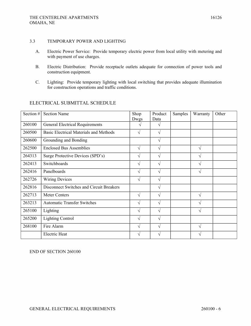
THE CENTERLINE APARTMENTS 16126OMAHA, NE
GENERAL ELECTRICAL REQUIREMENTS 260100 - 6
3.3 TEMPORARY POWER AND LIGHTING
A. Electric Power Service: Provide temporary electric power from local utility with metering and with payment of use charges.
B. Electric Distribution: Provide receptacle outlets adequate for connection of power tools and construction equipment.
C. Lighting: Provide temporary lighting with local switching that provides adequate illumination for construction operations and traffic conditions.
ELECTRICAL SUBMITTAL SCHEDULE
Section # Section Name Shop Dwgs
Product Data
Samples Warranty Other
260100 General Electrical Requirements
260500 Basic Electrical Materials and Methods
260600 Grounding and Bonding
262500 Enclosed Bus Assemblies
264313 Surge Protective Devices (SPD’s)
262413 Switchboards
262416 Panelboards
262726 Wiring Devices
262816 Disconnect Switches and Circuit Breakers
262713 Meter Centers
263213 Automatic Transfer Switches
265100 Lighting
265200 Lighting Control
268100 Fire Alarm
Electric Heat
END OF SECTION 260100
THE CENTERLINE APARTMENTS 16126
OMAHA, NE
BASIC ELECTRICAL MATERIALS AND METHODS 260500 - 1
SECTION 260500 - BASIC ELECTRICAL MATERIALS AND METHODS
PART 1 - GENERAL
1.1 RELATED DOCUMENTS
A. Drawings and general provisions of the Contract, including General and Supplementary
Conditions and Division 1 Specification Sections, apply to this Section.
1.2 SUMMARY
A. This Section includes the following basic electrical materials and methods and shall apply to all
phases of the work specified, indicated on the drawings or required to provide for complete
installation of electrical systems.
1. Conduits.
2. Building wire and connectors.
3. Supporting devices for electrical components.
4. Outlet boxes.
5. Electrical identification.
6. Cutting and patching for electrical construction.
7. Fire Stopping.
8. Touchup painting.
1.3 MATERIAL QUALITY ASSURANCE
A. Electrical components, devices, and accessories: Listed and labeled as defined in NFPA 70,
Article 100, by a testing agency acceptable to authorities having jurisdiction, and marked for
intended use.
B. Comply with NFPA 70.
1.4 COORDINATION
A. Coordinate chases, slots, inserts, sleeves, and openings with general construction work and
arrange in building structure during progress of construction to facilitate the electrical
installations that follow.
1. Set inserts and sleeves in poured-in-place concrete, masonry work, and other structural
components as they are constructed.
B. Sequence, coordinate, and integrate installing of electrical materials and equipment with other
trades.

THE CENTERLINE APARTMENTS 16126
OMAHA, NE
BASIC ELECTRICAL MATERIALS AND METHODS 260500 - 2
C. Coordinate location of access panels and doors for electrical items that are concealed by finished
surfaces.
D. Where electrical identification devices are applied to field-finished surfaces, coordinate
installation of identification devices with completion of finished surface.
E. Where electrical identification markings and devices will be concealed by acoustical ceilings and
similar finishes, coordinate installation of these items before ceiling installation.
F. Motors, equipment, controls, etc. shall be furnished, mounted and connected according to the
following schedule unless otherwise noted (E =Electrical Contractor, M =Mechanical
Contractor):
G.
Item Furnished By Set in place or
mounted by
Power wiring and
connection by
Control Wiring
and connection
by
1) Disconnect switches, thermal
overload switches, manual
operating switches
a) Furnished as part of factory
wired mechanical equipment
M M E --
b) Loose mounted E E E --
2) Transformers
a) Serving 24 Volt control power M(1) M E M
3) Push-button stations, pilot lights E E E E
4) Low voltage controls and
thermostats
M M M M(2)
5) Motorized valves, and float
controls for tanks and sumps
M M E M
6) Motorized control valves, damper
motors, solenoid valves, etc.
a) Line Voltage M M E M
b) Low Voltage M M M M
7) Factory pre-wired control/power
panels including remote sensing
devices
M M E M(3)
8) Electric wall and unit heaters E E E E
9) Fire protection controls M M E E
10) Fire Smoke Dampers
a) At air handling unit (24 Volt) M M M M
b) In space (120 Volt) M M E E(4)
11) Fire and smoke detectors including
relays for fan shutdown
E E E E(5)
H. Notes:
1. When control power is not available, mechanical contractor shall provide control
transformers as required to power all valves, dampers, etc.
THE CENTERLINE APARTMENTS 16126
OMAHA, NE
BASIC ELECTRICAL MATERIALS AND METHODS 260500 - 3
2. Conduit rough-in for thermostats by electrical contractor where indicated on plans.
3. Remote condensing units and heat pumps control wiring including wiring of remote
sensors by mechanical. Control circuit feeders by mechanical unless shown otherwise.
4. Smoke dampers will be specified as 115 volt (verify) with wiring by Electrical Contractor
and control from the fire alarm panel. Smoke detectors furnished by electrical contractor
are required to make dampers operate.
5. Wiring from alarm contacts to alarm system by Electrical; control function wiring by
Mechanical.
1.5 DELIVERY, STORAGE, AND HANDLING
A. Each contractor shall make provisions for delivery and safe storage of materials. Materials shall
be delivered in a timely manner to expedite the work.
B. Protect stored piping, supplies and equipment from cold, moisture and dirt. Elevate above grade.
Do not exceed structural capacity of floor, if stored inside.
PART 2 - PRODUCTS
2.1 CONDUITS
A. Electrical metallic tubing (EMT): ANSI C80.3 and UL 797, zinc-coated steel with steel or die
cast, set-screw or compression type fittings.
B. Flexible metal conduit (FMC): UL 1, Zinc-coated steel.
C. Type NM cable: UL Standard 83, UL Standard 719.
D. Liquidtight flexible metal conduit (LFMC): Flexible steel conduit with PVC jacket and
complying with UL 360.
E. Rigid nonmetallic conduit (RNC): NEMA TC 2 and UL 651, EPC-40 (schedule 40) PVC, with
NEMA TC3 fittings.
F. Electrical Nonmetallic Tubing (ENT): NEMA TC 13 and UL 1569.
G. Metal Clad Cable (MC): NEMA WC 70 and UL 1653.
H. Uses Permitted:
1. Use the following raceways for apartment (residential) indoor installations:
a. Exposed branch circuits: EMT
b. Concealed branch circuits: Type NM Cable, MC Cable
c. Connection to vibrating equipment: FMC; except in wet or damp locations,
use LFMC.

THE CENTERLINE APARTMENTS 16126
OMAHA, NE
BASIC ELECTRICAL MATERIALS AND METHODS 260500 - 4
d. Boxes and enclosures: NEMA 250, Type 1, unless otherwise indicated.
Fiberglass where Type NM cable is used
e. Panelboard feeders: EMT, PVC
2. Use the following raceways for apartment corridor installations:
a. Exposed branch circuits: EMT.
b. Concealed branch circuits: EMT, ENT.
c. Underground branch circuits: PVC
d. Connection to vibrating equipment: FMC; except in wet or damp locations,
use LFMC.
e. Boxes and enclosures: NEMA 250, Type 1, unless otherwise indicated
f. Panelboard feeders: EMT, PVC
3. Use the following raceways for commons areas and parking garages:
a. Exposed branch circuits: EMT.
b. Concealed branch circuits: EMT, ENT.
c. Underground branch circuits: PVC
d. Connection to vibrating equipment: FMC; except in wet or damp locations,
use LFMC.
e. Boxes and enclosures: NEMA 250, Type 1, unless otherwise indicated.
f. Panelboard feeders: EMT, PVC
4. At motors:
a. Connect motors and equipment subject to vibration, noise transmission, or
movement with FMC of 72-inch maximum length.
b. Damp locations: LFMC.
I. Conduit fittings: Specifically designed for the conduit type with which used. Comply with
NEMA FB 1 and UL 514B.
2.2 CONDUCTORS
A. Conductors and conductor insulation: Comply with NEMA WC 70.
B. Conductors, No. 10 AWG and Smaller: Solid or stranded copper.
C. Conductors, larger than No. 10 AWG: Stranded copper.
D. Insulation: Thermoplastic, rated at 75 deg C minimum.
1. Feeders: Type THHN/THWN insulated conductors in conduit.
2. Underground Feeders and Branch Circuits: Type THWN in conduit.
3. Branch Circuits: Type THHN/THWN insulated conductors in conduit.
4. Circuits over 100 feet from GFCI devices: Low-leakage XHHW in conduit.

THE CENTERLINE APARTMENTS 16126
OMAHA, NE
BASIC ELECTRICAL MATERIALS AND METHODS 260500 - 5
E. Wire connectors and splices: Units of size, ampacity rating, material, type, and class suitable for
service indicated.
F. Unless otherwise indicated on the drawings, circuits are to be 20 amps with #12 AWG wire. #14
AWG wire for 15 amp circuits is permitted for use in apartment units only.
G. A green ground shall be installed with all branch and feeder circuits. Unless otherwise indicated
on the drawings, ground wires are to be #12 AWG.
H. Provide a dedicated neutral conductor for each 120V branch circuit unless otherwise indicated on
drawings. At Contractor’s option, handle-ties for multi-wire branch circuits with a shared neutral
shall be allowed.
2.3 SUPPORTING DEVICES
A. Material: Cold-formed steel, with corrosion-resistant coating acceptable to authorities having
jurisdiction.
B. Metal items for use outdoors or in damp locations: Hot-dip galvanized steel.
C. Slotted-steel channel supports: Flange edges turned toward web, and 9/16-inch- diameter slotted
holes at a maximum of 2 inches o.c., in webs.
D. Conduit and cable supports: Manufactured clevis hangers, riser clamps, straps, threaded C-
clamps with retainers, ceiling trapeze hangers, wall brackets, and spring-steel clamps or click-
type hangers.
1. In general, use the following support methods for outdoor conduit installations:
a. Individual exposed conduit: 1” and smaller; 2 hole straps.
b. Individual exposed conduit: 1-1/4” and larger; Minerallac.
c. Paired individual exposed conduit: Minerallac.
d. Rack exposed conduit: Unistrut with strut straps.
e. Concealed in concrete pour: Approved iron tie wire.
2. In general, use the following support methods for indoor conduit installations:
a. Individual exposed conduit: 1” and smaller; 2 hole straps.
b. Individual exposed conduit: 1-1/4” and larger; Minerallac.
c. Individual lighting and power above lay-in ceilings: Dedicated ceiling wire
with Caddy clips.
d. Racked exposed or concealed conduit: Unistrut with strut straps.
E. Pipe sleeves: ASTM A 53, Type E, Grade A, Schedule 40, galvanized steel, plain ends.
F. Expansion anchors: Carbon-steel wedge or sleeve type.
G. Toggle bolts: All-steel springhead type.

THE CENTERLINE APARTMENTS 16126
OMAHA, NE
BASIC ELECTRICAL MATERIALS AND METHODS 260500 - 6
H. Powder-driven threaded studs: Heat-treated steel.
2.4 BOXES
A. Hollow wall and ceiling spaces: Outlet boxes for concealed applications shall be 4” square with
single or multiple gang plaster ring in round or square configuration to match the device or fixture
being installed. Depth of ring shall be selected so that face of ring is recessed back from face of
finished surface by approximately 1/8”.
B. Masonry walls: Outlet boxes in masonry walls shall be 4” square with single or multiple gang
masonry rings with square edges. Masonry boxes may also be used where 4” square boxes are
impractical. Slush boxes in place to prevent movement within walls. Flush mounted boxes and
conduit are to be used unless otherwise indicated.
C. Exposed exterior boxes: Where exposed boxes are required, they shall be the cast type with
threaded hubs and gasketed covers. Use of these boxes is by approval only. Flush mounted boxes
and conduit are to be used unless otherwise indicated.
D. Interior junction boxes: Interior junction boxes shall be 4” square minimum with knock outs as
required. Larger boxes may be required and shall be sized per NEC. Provide a flat steel
coverplate. Match junction box type to raceway or conductor system:
1. EMT: Sheet Metal Outlet and Device Boxes: Comply with NEMA OS 1 and UL 514A.
2. RNC: Type EPC-40-PVC, complying with NEMA TC 2 and UL 651 unless otherwise
indicated.
3. NM Cable: Fiberglass nonmetallic outlet and device boxes. Comply with NEMA OS 2 and
UL 514C.
E. Specialty junction boxes larger than 4 11/16”: Junction and pull boxes shall be sized per NEC
and arranged to facilitate pulling or splicing. Boxes shall be steel without knock outs, with hinged
or screw on cover plates.
F. Floor boxes: See “Wiring Devices” Specification or the drawings.
2.5 ELECTRICAL IDENTIFICATION
A. Underground warning tape: Permanent, bright-colored, continuous-printed, vinyl tape with the
following features:
1. Not less than 6 inches wide by 4 mils thick.
2. Compounded for permanent direct-burial service.
3. Embedded continuous metallic strip or core.
4. Printed legend that indicates type of underground line.
B. Tape markers for wire: Vinyl or vinyl-cloth, self-adhesive, wraparound type with preprinted
numbers and letters.

THE CENTERLINE APARTMENTS 16126
OMAHA, NE
BASIC ELECTRICAL MATERIALS AND METHODS 260500 - 7
C. Engraved-plastic labels, signs, and instruction plates: Engraving stock, melamine plastic laminate
punched or drilled for mechanical fasteners 1/16-inch minimum thickness for signs up to 20 sq.
in. and 1/8-inch minimum thickness for larger sizes. Engraved legend in black letters on white
background.
2.6 ACCESS DOORS
A. Prime coated 14 gauge steel, flush, with screw driver operated cam lock. Frame to accommodate
construction type; size as indicated.
PART 3 - EXECUTION
3.1 UTILITY COORDINATION
A. Utility locations indicated on drawings are approximate and the most accurate information
available at the time of design. Prior to equipment and conduit installation, the contractor shall
coordinate exact installation details and modify work plan accordingly to meet utility
requirements. Correspond with utility company prior to any site development that may impact
the installation such as irrigation installation, concrete or asphalt installation, landscaping, etc.
B. Contact utility locating services prior to digging. Coordinate all final utility equipment locations
with Engineer prior to pouring pads.
3.2 ELECTRICAL EQUIPMENT INSTALLATION
A. Neatness and craftsmanship shall be a priority. Installations shall be subject to regular
observations performed by the Engineer or the Engineer’s Representative. If an installation is
deemed unsatisfactory by the Engineer or the Engineer’s Representative due to quality of
workmanship, code conflicts or deviations from the Construction Drawings or Specifications, the
Contractor shall remedy the installation to the satisfaction of the Engineer.
B. Inspect installed components for damage and faulty work, including the following:
1. Conduits.
2. Building wire and connectors.
3. Supporting devices for electrical components.
4. Electrical identification.
5. Concrete bases.
6. Cutting and patching for electrical construction.
7. Touchup painting.
C. Headroom maintenance: If mounting heights or other location criteria are not indicated, arrange
and install components and equipment to provide the maximum possible headroom.
D. Materials and components: Install level, plumb, and parallel and perpendicular to other building
systems and components, unless otherwise indicated.

THE CENTERLINE APARTMENTS 16126
OMAHA, NE
BASIC ELECTRICAL MATERIALS AND METHODS 260500 - 8
E. Equipment: Install to facilitate service, maintenance, and repair or replacement of components.
Connect for ease of disconnecting, with minimum interference with other installations.
F. Right of way: Give to conduits and piping systems installed at a required slope.
3.3 CONDUIT AND CABLE INSTALLATION
A. Conceal conduit and cables, unless otherwise indicated, within finished walls, ceilings, and floors.
B. Install conduit and cables at least 6 inches away from parallel runs of flues or hot-water pipes.
Locate horizontal conduit runs above water piping.
C. Use temporary conduit caps to prevent foreign matter from entering.
D. Make conduit bends and offsets so ID is not reduced. Keep legs of bends in the same plane and
straight legs of offsets parallel, unless otherwise indicated.
E. Use conduit and cable fittings compatible with conduit and cables and suitable for use and
location.
F. Conduits may be installed embedded in concrete under the following conditions:
1. Contractor shall receive approval from a structural engineer if conduit is to be located in
structural concrete.
2. Leave at least 2-inch concrete cover.
3. Do not displace more than 1/3 of the concrete thickness of the slab. For example, if the slab
thickness is 3”, maximum conduit size is to be 1” OD.
4. Secure conduit to reinforcing rods to prevent sagging or shifting during concrete
placement.
5. Where multiple conduits are run in an area, space conduit laterally to prevent voids in
concrete. Fan out conduit runs for a minimum spacing of no less than 3 times the diameter
of the larger conduit in a group. Do not place conduits within 12” of supporting beams,
walls and columns.
6. Install conduit larger than 1-inch trade size parallel to or at right angles to main
reinforcement. Where conduit is at right angles to reinforcement, place conduit close to
slab support.
7. Where floor finish is to be exposed concrete, avoid excessive underfloor conduits and
maximize cover over conduits to avoid floor cracking.
8. Transition from nonmetallic tubing to Schedule 80 nonmetallic conduit, rigid steel conduit,
or IMC before rising above floor.
G. Make bends in exposed parallel or banked runs from same centerline to make bends parallel. Use
factory elbows where elbows can be installed parallel; otherwise, provide field bends for exposed
parallel conduits.
H. Install pull wires in empty conduits. Use No. 14 AWG zinc-coated steel or monofilament plastic
line with not less than 200-lb tensile strength. Leave at least 12 inches of slack at each end of the
pull wire.

THE CENTERLINE APARTMENTS 16126
OMAHA, NE
BASIC ELECTRICAL MATERIALS AND METHODS 260500 - 9
I. Install interior telephone and signal system conduits in maximum lengths of 150 feet and with a
maximum of two 90-degree bends or equivalent. Separate lengths with pull or junction boxes
where necessary to comply with these requirements, in addition to requirements above.
J. Install exterior telephone and signal system conduits in maximum lengths of 500 feet and with a
minimal number of 90-degree bends.
K. Utilize sweep elbows for all telephone and signal system conduits 2” and larger.
L. All conduits routed through unfinished spaces shall be routed as high as allowable to avoid future
conflicts with build out.
M. Route conduits parallel to building structural members in a neat and orderly manner.
3.4 CONDUIT SUPPORT INSTALLATION
A. Install support devices to securely and permanently fasten and support electrical components.
B. Install individual and multiple conduit hangers and riser clamps to support conduits. Provide U-
bolts, clamps, attachments, and other hardware necessary for hanger assemblies and for securing
hanger rods and conduits.
C. Size supports for multiple conduits so capacity can be increased by a 25 percent minimum in the
future.
D. Install 1/4-inch diameter or larger threaded steel hanger rods, unless otherwise indicated.
E. Separately support cast boxes that are threaded to conduits and used for fixture support. Support
sheet-metal boxes directly from the building structure or by bar hangers. If bar hangers are used,
attach bar to conduits on opposite sides of the box and support the conduit with an approved
fastener not more than 24 inches from the box.
F. Install metal channel racks for mounting cabinets, panelboards, disconnect switches, control
enclosures, pull and junction boxes, transformers, and other devices unless components are
mounted directly to structural elements of adequate strength. Use factory hardware for all
connections and assemblies including 45 and 90 degree attachment hardware.
G. Install sleeves for cable and conduit penetrations of concrete slabs and walls unless core-drilled
holes are used. Install sleeves for cable and conduit penetrations of masonry and fire-rated
gypsum walls and of all other fire-rated floor and wall assemblies. Install sleeves during erection
of concrete and masonry walls.
H. Install PVC sleeves for grounding cable riser penetrations of concrete slabs. Where ground wires
are run through metal sleeves use grounding bushings on both ends of the conduit or sleeve.
I. Securely fasten electrical items and their supports to the building structure, unless otherwise
indicated. Perform fastening according to the following unless other fastening methods are
indicated:

THE CENTERLINE APARTMENTS 16126
OMAHA, NE
BASIC ELECTRICAL MATERIALS AND METHODS 260500 - 10
1. Masonry: Toggle bolts on hollow masonry units and expansion bolts on solid masonry
units.
2. New concrete: Concrete inserts with machine screws and bolts.
3. Light steel: Sheet-metal screws.
4. Fasteners: Select so the load applied to each fastener does not exceed 25 percent of its
proof-test load.
3.5 WIRING INSTALLATION
A. Install splices and taps that are compatible with conductor material and that possess equivalent or
better mechanical strength and insulation ratings than unspliced conductors.
B. Install wiring at outlets with at least 12 inches of slack conductor at each outlet.
C. Connect outlet and component connections to wiring systems and to ground. Tighten electrical
connectors and terminals, according to manufacturer's published torque-tightening values.
3.6 POSITION OF DEVICE OUTLETS
A. Outlets shall be installed at the height indicated below unless otherwise noted. All heights of
outlets are measured from finished floor to centerline of device. Heights may be adjusted as
necessary to clear wall mounted cabinets, fin tube convectors, unit heaters, etc. Where installed
in masonry walls, mounting heights may be adjusted to correspond to block coursing. In no case
shall outlets be mounted below 15” or switches above 48”:
1. Wall switches 44”.
2. Receptacle outlet (general) 16”.
3. Receptacle outlet serving countertops 4” above counter or top of backsplash unless
otherwise noted.
4. Exterior receptacles 24”
5. Communications outlet Match adjacent outlets.
6. Communication system call station 48” to the highest button.
7. Fire alarm signals 82” or 6” below ceiling (whichever is lower).
8. Fire alarm pull stations 48”.
9. Exit lights 4” between top of door frame and bottom of
exit light where possible.
3.7 ELECTRICAL IDENTIFICATION
A. Install at locations for most convenient viewing without interference with operation and
maintenance of equipment.
B. Coordinate names, abbreviations, colors, and other designations used for electrical identification
with corresponding designations indicated in the Contract Documents or required by codes and
standards. Use consistent designations throughout Project.

THE CENTERLINE APARTMENTS 16126
OMAHA, NE
BASIC ELECTRICAL MATERIALS AND METHODS 260500 - 11
C. Self-Adhesive Identification Products: Clean surfaces before applying.
D. Tag and label circuits designated to be extended in the future. Identify source and circuit numbers
in each cabinet, pull and junction box, and outlet box. Color-coding may be used for voltage and
phase identification.
E. Install warning markers directly above power and communication lines during trench backfilling
for underground power, control, signal, and communication lines. Locate marker 6 to 8 inches
below finished grade unless required otherwise by NEC. Markers shall be continuous and
detectable with a metal detector from above ground after backfilling. Provide one strip of marker
for each 16 inches of width if multiple lines are installed in a common trench or concrete envelope.
F. Color-code 208/120-V system secondary service, feeder, and branch-circuit conductors
throughout the secondary electrical system as follows:
1. Phase A: Black.
2. Phase B: Red.
3. Phase C: Blue.
4. Neutral: White.
5. Ground: Green.
3.8 FIRESTOPPING
A. Apply firestopping to cable and raceway penetrations of fire-rated floor and wall assemblies to
achieve fire-resistance rating of the assembly and to resist passage of smoke and other gases.
Products designed to achieve a fire or smoke resistance rating shall not be used in locations where
such ratings are not required by AHJ. Coordinate location requirements with other disciplines and
AHJ prior to installation.
1. Limit air leakage to 5.0cfm per square foot tested in accordance with UL 1479.
2. Materials labeled by a qualified testing agency acceptable to AHJ.
3. Comply with manufacturer's written installation instructions and published drawings
4. Identify penetration firestopping with preprinted metal or plastic labels. Attach labels
permanently to surfaces adjacent to and within 6 inches of firestopping edge so labels will
be visible to anyone seeking to remove penetrating items or firestopping. Use mechanical
fasteners or self-adhering-type labels with adhesives capable of permanently bonding
labels to surfaces on which labels are placed. Include the following information on labels:
a. The words "Warning - Penetration Firestopping - Do Not Disturb. Notify
Building Management of Any Damage."
b. Contractor's name, address, and phone number.
c. Designation of applicable testing and inspecting agency.
d. Date of installation.
e. Manufacturer's name.
f. Installer's name.
B. All firestopping assemblies shall be from one manufacturer. Match manufacturer used by other
trades or as directed by general contractor.

THE CENTERLINE APARTMENTS 16126
OMAHA, NE
BASIC ELECTRICAL MATERIALS AND METHODS 260500 - 12
C. Where electrical outlets are to be installed in fire rated walls, provide FlameSafe FSP1077 putty
pads or equal to maintain adequate fire rating.
D. Where lighting fixtures or other electrical devices are to be installed in fire rated ceilings, provide
Tenmat Fire Rated Light Covers or equal to maintain adequate fire rating.
3.9 HOUSEKEEPING PADS
A. Provide a 3-1/2 inch tall concrete housekeeping pad for all floor mounted interior electrical
equipment as follows:
1. Pad shall extend 4-6” beyond all sides of equipment, except in the back for switchboards
mounted tight against the wall.
2. Constructed of 3000 psi concrete.
3. Provide 6” x 6” #4 welded wire mesh.
4. Securely bond pad to floor by roughing the floor and coating with cement grout.
3.10 CUTTING AND PATCHING
A. Cut, channel, chase, and drill floors, walls, partitions, ceilings, and other surfaces necessary for
electrical installations. Perform cutting by skilled mechanics of trades involved.
B. Repair cut surfaces to match adjacent surfaces.
3.11 CONSTRUCTION LAYOUT
A. Layout work in advance of installation using data and measurements from the site, the appropriate
architectural and structural drawings and shop drawings.
B. Confirm adequate clearance for installation, operation, maintenance and code required clearance
including items installed by other contractors.
C. If layout to provide clearance is not possible, promptly notify Architect/Engineer for clarification.
3.12 DATA AND MEASUREMENTS
A. The data given herein and on the drawings is as accurate as could be secured. The existence and
location of construction as indicated is not guaranteed. Before beginning work investigate and
verify the existence and location of items affecting work. Obtain exact locations, measurements,
levels, etc., at the site and adapt work to actual conditions.
B. Only Architectural drawings, Structural drawings, and site measurements may be utilized in
calculations. Mechanical and electrical drawings are diagrammatic or schematic.
3.13 REFINISHING AND TOUCHUP PAINTING

THE CENTERLINE APARTMENTS 16126
OMAHA, NE
BASIC ELECTRICAL MATERIALS AND METHODS 260500 - 13
A. Refinish and touch up paint.
1. Clean damaged and disturbed areas and apply primer, intermediate, and finish coats to suit
the degree of damage at each location.
2. Follow paint manufacturer's written instructions for surface preparation and for timing and
application of successive coats.
3. Repair damage to galvanized finishes with zinc-rich paint recommended by manufacturer.
4. Repair damage to PVC or paint finishes with matching touchup coating recommended by
manufacturer.
3.14 CLEANING AND PROTECTION
A. On completion of installation, including outlets, fittings, and devices, inspect exposed finish.
Remove burrs, dirt, paint spots, and construction debris.
B. Protect equipment and installations and maintain conditions to ensure that coatings, finishes, and
cabinets are without damage or deterioration at time of Substantial Completion.
END OF SECTION 260500

THE CENTERLINE APARTMENTS 16126
OMAHA, NE
GROUNDING AND BONDING 260600 - 1
SECTION 260600 - GROUNDING AND BONDING
PART 1 - GENERAL
1.1 RELATED DOCUMENTS
A. Drawings and general provisions of the Contract, including General and Supplementary
Conditions and Division 1 Specification Sections, apply to this Section.
1.2 SUMMARY
A. This Section includes methods and materials for grounding systems and equipment.
1.3 SUBMITTALS
A. Product Data: For each type of product indicated.
B. Field quality-control test reports.
C. Operation and Maintenance Data: For grounding, include the following in emergency, operation,
and maintenance manuals:
1. Instructions for periodic testing and inspection of grounding features at grounding
connections for separately derived systems based on NFPA 70B.
a. Tests shall be to determine if ground resistance or impedance values remain
within specified maximums, and instructions shall recommend corrective
action if they do not.
b. Include recommended testing intervals.
1.4 QUALITY ASSURANCE
A. Electrical Components, Devices, and Accessories: Listed and labeled as defined in NFPA 70,
Article 100, by a testing agency acceptable to authorities having jurisdiction, and marked for
intended use.
B. Comply with UL 467 for grounding and bonding materials and equipment.

THE CENTERLINE APARTMENTS 16126
OMAHA, NE
GROUNDING AND BONDING 260600 - 2
PART 2 - PRODUCTS
2.1 CONDUCTORS
A. Insulated Conductors: Copper wire or cable insulated for 600 V unless otherwise required by
applicable Code or authorities having jurisdiction.
B. Bare Copper Conductors:
1. Solid Conductors: ASTM B 3.
2. Stranded Conductors: ASTM B 8.
3. Tinned Conductors: ASTM B 33.
4. Bonding Conductor: See riser diagram.
C. Grounding Bus Bars:
1. Rectangular annealed copper bar
2. .25” nominal thickness
3. Dimensions: See drawings
4. Stainless steel wall brackets with insulators, 5/8” diameter mounting bolts with lock
washers
D. Rectangular bars of annealed copper with pre-drilled hole pattern, per details on the drawings;
with insulators.
2.2 CONNECTORS
A. Listed and labeled by a nationally recognized testing laboratory acceptable to authorities having
jurisdiction for applications in which used, and for specific types, sizes, and combinations of
conductors and other items connected.
B. Bolted Connectors for Conductors and Pipes: Copper or copper alloy, bolted pressure-type, with
at least two bolts.
1. Pipe Connectors: Clamp type, sized for pipe.
2. Bus Bars: Compression type, two hole.
C. Welded Connectors: Exothermic-welding kits of types recommended by kit manufacturer for
materials being joined and installation conditions.
2.3 GROUNDING ELECTRODES
A. Ground Rods: Copper-clad steel, 5/8” diameter by 120 inches.
B. Ufer Ground (Concrete-Encased Grounding Electrode): #4 bare copper in 25’ of concrete footing.

THE CENTERLINE APARTMENTS 16126
OMAHA, NE
GROUNDING AND BONDING 260600 - 3
PART 3 - EXECUTION
3.1 APPLICATIONS
A. Conductors: Install solid conductor for No. 8 AWG and smaller, and stranded conductors for
No. 6 AWG and larger, unless otherwise indicated.
B. Underground Grounding Conductors: Install bare copper conductor, No. 4 AWG minimum.
1. Bury at least 24 inches (600 mm) below grade.
C. Grounding Bus Bars: Install in electrical and telephone equipment rooms, in rooms housing
service equipment, and elsewhere as indicated.
1. See plans for bus requirements.
D. Conductor Terminations and Connections:
1. Pipe and Equipment Grounding Conductor Terminations: Bolted connectors.
2. Underground Connections: Welded connectors
3. Connections to Ground Rods: Bolted connectors.
4. Connections to Conduits: Insulated grounding bushings
5. Connections to Busbars: Bolted connections.
3.2 GROUNDING UNDERGROUND DISTRIBUTION SYSTEM COMPONENTS
A. Comply with IEEE C2 grounding requirements.
B. Install two parallel ground rods if resistance to ground by a single, ground-rod electrode exceeds
25 ohms.
C. Drive ground rods until tops are 12 inches (300 mm) below finished grade in undisturbed earth.
D. Ground-Rod Connections: Install bolted connectors for underground connections and
connections to rods.
E. Protect grounding conductors running on surface of wood poles with molding extended from
grade level up to and through communication service and transformer spaces.
3.3 EQUIPMENT GROUNDING
A. Install insulated equipment grounding conductors with all feeders and branch circuits.
B. Install insulated equipment grounding conductors with the following items, in addition to those
required by NFPA 70:
1. All feeders and branch circuits, including:

THE CENTERLINE APARTMENTS 16126
OMAHA, NE
GROUNDING AND BONDING 260600 - 4
a. Feeders and branch circuits.
b. Lighting circuits.
c. Receptacle circuits.
d. Single-phase motor and appliance branch circuits.
e. Three-phase motor and appliance branch circuits.
f. Flexible raceway runs.
g. Armored and metal-clad cable runs.
h. Grounding and bonding of the pool and pool equipment per NEC 680.6 and
680.26
3.4 INSTALLATION
A. Grounding Conductors: Route along shortest and straightest paths possible, unless otherwise
indicated or required by Code. Avoid obstructing access or placing conductors where they may
be subjected to strain, impact, or damage.
B. Ground Rods: Drive rods until tops are 2 inches (50 mm) below finished floor or final grade,
unless otherwise indicated.
1. Interconnect ground rods with grounding electrode conductor below grade and as otherwise
indicated. Make connections without exposing steel or damaging coating, if any.
C. Bonding Straps and Jumpers: Install in locations accessible for inspection and maintenance,
except where routed through short lengths of conduit.
1. Bonding to Structure: Bond straps directly to basic structure, taking care not to penetrate
any adjacent parts.
2. Bonding to Equipment Mounted on Vibration Isolation Hangers and Supports: Install so
vibration is not transmitted to rigidly mounted equipment.
3. Use exothermic-welded connectors for outdoor locations, but if a disconnect-type
connection is required, use a bolted clamp.
D. Bonding for Metal Enclosed Panelboards: Provide insulated grounding bushings and #4 AWG
jumper on conduit that does not terminate in panelboard enclosure bottom plate.
E. Grounding and Bonding for Piping:
1. Metal Water Service Pipe, Including Fire Service: Install insulated copper grounding
conductors, in conduit, from building's main service equipment, or grounding bus, to main
metal water service entrances to building. Connect grounding conductors to main metal
water service pipes, using a bolted clamp connector or by bolting a lug-type connector to
a pipe flange, using one of the lug bolts of the flange. Where a dielectric main water fitting
is installed, connect grounding conductor on street side of fitting. Bond metal grounding
conductor conduit or sleeve to conductor at each end.
2. Water Meter Piping: Use braided-type bonding jumpers to electrically bypass water
meters. Connect to pipe with a bolted connector.
3. Bond each aboveground portion of gas piping system downstream from equipment shutoff
valve.

THE CENTERLINE APARTMENTS 16126
OMAHA, NE
GROUNDING AND BONDING 260600 - 5
F. Ufer Ground (Concrete-Encased Grounding Electrode): Install according to NFPA 70, using a
minimum of 25’ of bare copper conductor not smaller than No. 4 in concrete footing.
1. Bond grounding conductor to reinforcing steel in at least four locations and to anchor bolts.
3.5 FIELD QUALITY CONTROL
A. Perform tests and inspections.
1. Manufacturer's Field Service: Engage a factory-authorized service representative to
inspect components, assemblies, and equipment installations, including connections, and
to assist in testing.
B. Tests and Inspections:
1. After installing grounding system but before permanent electrical circuits have been
energized, test for compliance with requirements.
2. Inspect physical and mechanical condition. Verify tightness of accessible, bolted,
electrical connections with a calibrated torque wrench according to manufacturer's written
instructions.
3. Test completed grounding system at each location where a maximum ground-resistance
level is specified, at service disconnect enclosure grounding terminal, and at individual
ground rods. Make tests at ground rods before any conductors are connected.
a. Measure ground resistance no fewer than two full days after last trace of
precipitation and without soil being moistened by any means other than
natural drainage or seepage and without chemical treatment or other artificial
means of reducing natural ground resistance.
b. Perform tests by fall-of-potential method according to IEEE 81.
4. Prepare dimensioned Drawings locating each test well, ground rod and ground-rod
assembly, and other grounding electrodes. Identify each by letter in alphabetical order,
and key to the record of tests and observations. Include the number of rods driven and their
depth at each location, and include observations of weather and other phenomena that may
affect test results. Describe measures taken to improve test results.
C. Grounding system will be considered defective if it does not pass tests and inspections.
D. Prepare test and inspection reports.
E. Report measured ground resistances that exceed the following values:
1. Power and Lighting Equipment or System with Capacity of 500 to 1000 kVA: 5 ohms.
F. Excessive Ground Resistance: If resistance to ground exceeds specified values, notify
Architect/Engineer promptly and include recommendations to reduce ground resistance.
END OF SECTION 260600

THE CENTERLINE APARTMENTS 16126
OMAHA, NE
SWITCHBOARDS 262413 - 1
SECTION 262413 - SWITCHBOARDS
PART 1 - GENERAL
1.1 RELATED DOCUMENTS
A. Drawings and general provisions of the Contract, including General and Supplementary
Conditions and Division 1 Specification Sections, apply to this Section.
1.2 SUMMARY
A. This Section includes service and distribution switchboards, overcurrent protective devices, and
associated auxiliary equipment rated 600 V and less.
B. Related Sections include the following:
1. Division 26 Section "General Electrical Requirements."
2. Division 26 Section "Basic Electrical Materials and Methods."
3. Division 26 Section "Grounding."
4. Division 26 Section "Surge Protective Devices (SPDs)."
1.3 SUBMITTALS
A. Product Data: For each type of switchboard, overcurrent protective device, ground-fault
protector, accessory, and component indicated. Include dimensions and manufacturers' technical
data on features, performance, electrical characteristics, ratings, and finishes.
B. Shop Drawings: For each switchboard and related equipment.
1. Dimensioned plans, elevations, sections, and details, including required clearances and
service space around equipment. Show tabulations of installed devices, equipment
features, and ratings. Include the following:
a. Enclosure types and details for types other than NEMA 250, Type 1.
b. Bus materials, configuration, current, and voltage ratings.
c. Short-circuit current rating of switchboards and overcurrent protective
devices.
d. Descriptive documentation of options or accessories such as barriers specified
for electrical insulation and isolation, metering, controls, interlocks, etc.
e. Utility company's metering provisions with indication of approval by utility
company.
f. UL listing for series rating of installed devices.
g. Features, characteristics, ratings, and factory settings of individual
overcurrent protective devices, and auxiliary components.

THE CENTERLINE APARTMENTS 16126
OMAHA, NE
SWITCHBOARDS 262413 - 2
h. SPD devices when integrated into equipment.
2. Wiring Diagrams: Diagram power, signal, and control wiring and differentiate between
manufacturer-installed and field-installed wiring.
C. Maintenance Data: For switchboards and components to include in maintenance manuals
specified in Division 1. In addition to requirements specified in Division 1 Section "Contract
Closeout," include the following:
1. Routine maintenance requirements for switchboards and all installed components.
2. Manufacturer's written instructions for testing and adjusting overcurrent protective devices.
3. Time-current curves, including selectable ranges for each type of overcurrent protective
device.
1.4 QUALITY ASSURANCE
A. Product Selection for Restricted Space: Drawings indicate maximum dimensions for
switchboards, including clearances between switchboards, and adjacent surfaces and other items.
Comply with indicated maximum dimensions.
1.5 DELIVERY, STORAGE, AND HANDLING
A. Deliver in sections of lengths that can be moved past obstructions in delivery path.
B. Store indoors in clean dry space with uniform temperature to prevent condensation. Protect from
exposure to dirt, fumes, water, corrosive substances, and physical damage.
1.6 PROJECT CONDITIONS
A. Installation Pathway: Remove and replace access fencing, doors, lift-out panels, and structures
to provide pathway for moving switchboards into place.
B. Existing Utilities: Do not interrupt utilities serving facilities occupied by Owner or others unless
permitted under the following conditions and then only after arranging to provide temporary
utility services according to requirements indicated:
1. Notify Architect/Engineer not less than seven days in advance of proposed utility
interruptions. Identify extent and duration of utility interruptions.
2. Indicate method of providing temporary utilities.
3. Proceed with utility interruptions only after receiving Architect/Engineer's written
authorizations.
1.7 COORDINATION

THE CENTERLINE APARTMENTS 16126
OMAHA, NE
SWITCHBOARDS 262413 - 3
A. Coordinate layout and installation of switchboards and components with other construction,
including conduit, piping, equipment, and adjacent surfaces. Maintain required workspace
clearances and required clearances for equipment access doors and panels.
B. Coordinate size and location of concrete bases. Cast anchor-bolt inserts into bases.
PART 2 - PRODUCT
2.1 MANUFACTURERS
A. Manufacturers: Subject to compliance with requirements, provide products by one of the
following:
1. Switchboards, Overcurrent Protective Devices, and Accessories:
a. Eaton Corp.; Cutler-Hammer Products.
b. General Electric Co.; Electrical Distribution & Control Div.
c. Siemens Energy & Automation, Inc.
d. Square D Co.
2.2 MANUFACTURED UNITS
A. Front-Connected, Front-Accessible Switchboard: Panel-mounted main device(s) and sections
rear aligned.
B. Nominal System Voltage: 208 Y/120 V.
C. Main-Bus Continuous: See power riser diagram and schedules for switchboard bus information.
2.3 FABRICATION AND FEATURES
A. Enclosure: Steel.
B. Enclosure Finish for Indoor Units: Factory-applied finish in manufacturer's standard gray finish
over a rust-inhibiting primer on treated metal surface.
C. Barriers: Between adjacent switchboard sections.
D. Bus Transition and Incoming Pull Sections: Matched and aligned with basic switchboard.
E. Removable, Hinged Rear Doors and Compartment Covers: Secured by captive thumb screws,
for access to rear interior of switchboard.
F. Buses and Connections: Three phase, four wire, unless otherwise indicated. Include the
following features:

THE CENTERLINE APARTMENTS 16126
OMAHA, NE
SWITCHBOARDS 262413 - 4
1. Phase- and Neutral-Bus Material: Hard-drawn copper of 98 percent conductivity or tin-
plated, high-strength, electrical-grade aluminum alloy.
a. If bus is aluminum, use copper or tin-plated aluminum for circuit-breaker line
connections.
b. If bus is copper, use copper for feeder circuit-breaker line connections.
2. Load Terminals: Insulated, rigidly braced, silver-plated, copper runback bus extensions
equipped with pressure connectors for outgoing circuit conductors. Provide load terminals
for future circuit-breaker positions at full ampere rating of circuit-breaker position.
3. Ground Bus: 1/4-by-2-inch minimum size, drawn-temper copper of 98 percent
conductivity, equipped with pressure connectors for feeder and branch-circuit ground
conductors. For busway feeders, extend insulated equipment grounding cable to busway
ground connection and support cable at intervals in vertical run.
4. Contact Surfaces of Buses: Silver plated.
5. Horizontal Main Phase Buses, Neutral Buses, and Equipment Ground Buses: Uniform
capacity for entire length of switchboard's main and distribution sections. Provide for
future extensions from both ends.
6. Vertical Main Phase Buses, Neutral Buses: Extend vertical bus from top to bottom of each
distribution section to allow maximum mounting of current and future devices.
7. Isolation Barrier Access Provisions: Permit checking of bus-bolt tightness.
8. Neutral Buses: 100 percent of the ampacity of the phase buses, unless otherwise indicated,
equipped with pressure connectors for outgoing circuit neutral cables. Bus extensions for
busway feeder neutral bus is braced.
G. Future Devices: Equip compartments with mounting brackets, supports, bus connections, and
appurtenances at full rating of circuit-breaker compartment.
2.4 SURGE PRORTECTIVE DEVICE (SPD)
A. Panelboard configured to physically accommodate integration of a SPD.
B. Panelboard phase, neutral, and ground busses configured to accommodate an integral SPD with
leads for each mode no longer than 12”.
2.5 OVERCURRENT PROTECTIVE DEVICES
A. Main Molded-Case Circuit Breaker: NEMA AB 1, with interrupting capacity to meet available
fault currents.
1. Electronic Trip Unit Circuit Breakers: RMS sensing; field-replaceable rating plug; with
the following field-adjustable settings:
a. Instantaneous trip.
b. Long- and short-time pickup levels.
c. Long- and short-time time adjustments.
2. Main Breaker Features and Accessories:

THE CENTERLINE APARTMENTS 16126
OMAHA, NE
SWITCHBOARDS 262413 - 5
a. Lugs: Mechanical style, suitable for number, size, trip ratings, and material
of conductors.
B. Arc Energy Reducing Maintenance Switch: For each circuit breaker rated 1200A or higher,
provide a selector switch to switch the circuit breaker instantaneous tripping characteristics to an
alternate setting temporarily during maintenance activity. Switch shall be lockable in either the
OFF or ON (maintenance mode) position. Provide with an LED indicator light to indicate that
switch is in maintenance mode. Provide with NO and NC contact for connection to building
management or alarm system.
PART 3 - EXECUTION
3.1 PROTECTION
A. Temporary Heating: Apply temporary heat to maintain temperature according to manufacturer's
written instructions.
3.2 EXAMINATION
A. Examine elements and surfaces to receive switchboards for compliance with installation
tolerances and other conditions affecting performance.
1. Proceed with installation only after unsatisfactory conditions have been corrected.
3.3 INSTALLATION
A. Install switchboards and accessories according to NEMA PB 2.1.
B. Support switchboards on concrete bases, 3 1/2-inch nominal thickness.
C. Temporary Lifting Provisions: Remove temporary lifting eyes, channels, and brackets and
temporary blocking of moving parts from switchboard units and components.
D. Operating Instructions: Frame and mount the printed basic operating instructions for
switchboards, including control and key interlocking sequences and emergency procedures.
Fabricate frame of finished wood or metal and cover instructions with clear acrylic plastic. Mount
on front of switchboards.
3.4 IDENTIFICATION
A. Identify field-installed conductors, interconnecting wiring, and components; provide warning
signs as specified in Division 26 Section "Basic Electrical Materials and Methods."

THE CENTERLINE APARTMENTS 16126
OMAHA, NE
SWITCHBOARDS 262413 - 6
B. Switchboard Nameplates: Label each switchboard compartment and overcurrent protective
device with engraved metal or laminated-plastic nameplate mounted with corrosion-resistant
screws.
3.5 CONNECTIONS
A. Install equipment grounding connections for switchboards with ground continuity to main
electrical ground bus.
B. Tighten electrical connectors and terminals according to manufacturer's published torque-
tightening values.
3.6 FIELD QUALITY CONTROL
A. Prepare for acceptance tests as follows:
1. Test insulation resistance for each switchboard bus, component, connecting supply, feeder,
and control circuit.
2. Test continuity of each circuit.
3.7 ADJUSTING
A. Set field-adjustable switches and circuit-breaker trip ranges.
3.8 CLEANING
A. On completion of installation, interior and exterior of switchboards. Remove paint splatters and
other spots. Vacuum dirt and debris; do not use compressed air to assist in cleaning. Repair
exposed surfaces to match original finish.
END OF SECTION 262413

THE CENTERLINE APARTMENTS 16126
OMAHA, NE
PANELBOARDS 262416 - 1
SECTION 262416 - PANELBOARDS
PART 1 - GENERAL
1.1 RELATED DOCUMENTS
A. Drawings and general provisions of the Contract, including General and Supplementary
Conditions and Division 1 Specification Sections, apply to this Section.
1.2 SUMMARY
A. This Section includes load centers and panelboards, overcurrent protective devices and associated
auxiliary equipment rated 600V and less for the following types:
1. Lighting and appliance branch-circuit panelboards.
2. Distribution panelboards.
B. Related Sections include the following:
1. Division 26 Section "General Electrical Requirements."
2. Division 26 Section "Basic Electrical Materials and Methods."
3. Division 26 Section "Grounding."
1.3 SUBMITTALS
A. Product Data: For each type of panelboard, overcurrent protective device, accessory, and
component indicated. Include dimensions and manufacturers' technical data on features,
performance, electrical characteristics, ratings, and finishes.
B. Shop Drawings: For each panelboard and related equipment.
1. Dimensioned plans, elevations, sections, and details. Show tabulations of installed devices,
equipment features, and ratings. Include the following:
a. Enclosure types and details for types other than NEMA 250, Type 1.
b. Panel designation (same as on drawings).
c. Bus configuration, current, and voltage ratings.
d. Short-circuit current rating of panelboards and overcurrent protective devices.
e. UL listing for series rating of installed devices.
f. Features, characteristics, ratings, and factory settings of individual
overcurrent protective devices, and auxiliary components.
g. Accessories (ground bar, contactor, door lock, etc.)
h. Mounting (flush or surface).
THE CENTERLINE APARTMENTS 16126
OMAHA, NE
PANELBOARDS 262416 - 2
2. Wiring Diagrams: Diagram power, signal, and control wiring and differentiate between
manufacturer-installed and field-installed wiring.
C. Maintenance Data: For panelboards and components to include in maintenance manuals specified
in Division 1. In addition to requirements specified in Division 1 Section "Contract Closeout,"
include the following:
1. Manufacturer's written instructions for testing and adjusting overcurrent protective devices.
2. Time-current curves, including selectable ranges for each type of overcurrent protective
device.
1.4 COORDINATION
A. Coordinate layout and installation of panelboards and components with other construction that
penetrates walls or is supported by them, including electrical and other types of equipment,
raceways, piping, and encumbrances to workspace clearance requirements.
1.5 EXTRA MATERIALS
A. Keys: Four spares of each type of panelboard cabinet lock.
PART 2 - PRODUCTS
2.1 MANUFACTURERS
A. Manufacturers: Subject to compliance with requirements, provide products by one of the
following:
1. Panelboards, Overcurrent Protective Devices, Controllers, Contactors, and Accessories:
a. Eaton Corp.; Cutler-Hammer Products.
b. General Electric Co.; Electrical Distribution & Control Div.
c. Siemens Energy & Automation, Inc.
d. Square D Co.
2. Fused Coordination Panelboards, Overcurrent Protective Devices, and Accessories:
a. Cooper-Bussman – Quick Spec Coordination Panelboard.
b. Mersen Fused Coordination Panelboard
2.2 FABRICATION AND FEATURES
A. Enclosures: Flush- and surface mounted cabinets. NEMA PB 1, Type 1, to meet environmental
conditions at installed location.
THE CENTERLINE APARTMENTS 16126
OMAHA, NE
PANELBOARDS 262416 - 3
1. Outdoor Locations: NEMA 250, Type 3R.
2. Other Wet or Damp Indoor Locations: NEMA 250, Type 4.
B. Front: Secured to box with concealed trim clamps. For surface-mounted fronts, match box
dimensions; for flush-mounted fronts, overlap box.
C. Finish: Manufacturer's standard enamel finish over corrosion-resistant treatment or primer coat.
D. Directory Card: With transparent protective cover, mounted inside metal frame, inside
panelboard door.
E. Bus: Hard-drawn copper, 98 percent conductivity or Tin-plated aluminum.
F. Main and Neutral Lugs: Mechanical type suitable for use with conductor material.
G. Equipment Ground Bus: Adequate for feeder and branch-circuit equipment ground conductors;
bonded to box.
H. Service Equipment Label: UL labeled for use as service equipment for panelboards with main
service disconnect switches.
I. Future Devices: Mounting brackets, bus connections, and necessary appurtenances required for
future installation of devices.
J. Feed-through Lugs: Mechanical type suitable for use with conductor material. Locate at opposite
end of bus from incoming lugs or main device, where indicated on the drawings.
2.3 PANELBOARD SHORT-CIRCUIT RATING
A. Series rated to interrupt symmetrical short-circuit current available at terminals.
2.4 LOAD CENTERS
A. Overcurrent Protective Devices: Plug-in, full-module circuit breaker.
B. Conductor Connectors: Mechanical type for main, neutral, and ground lugs and buses.
C. Load centers shall be used for apartment dwelling units only.
2.5 LIGHTING AND APPLIANCE BRANCH-CIRCUIT PANELBOARDS
A. Branch Overcurrent Protective Devices: Bolt-on (Plug-in for load centers only) circuit breakers,
replaceable without disturbing adjacent units.
B. Doors: Front mounted with concealed hinges; secured with flush latch with tumbler lock; keyed
alike.

THE CENTERLINE APARTMENTS 16126
OMAHA, NE
PANELBOARDS 262416 - 4
C. Load center construction shall not be acceptable other than installed in apartment units.
2.6 FUSED COORDINATION PANELBOARDS
A. Branch overcurrent protective devices: 1-, 2-, and 3-pole branch disconnects of ampacity listed
on the schedule.
B. Doors: Front mounted with concealed hinges; secured with flush latch with tumbler lock; keyed
alike.
C. Selective Coordination: Panelboards shall be specifically designed to address NEC selective
coordination requirements.
D. Provide with integral SPD
E. Spare Fuses: Provide six (6) spare fuses in spare fuse compartment. Spare fuse selection shall
match size of branch fuses with at least one of each size and quantities in proportion to quantity
of circuits in panel.
2.7 DISTRIBUTION PANELBOARDS
A. Doors: Front mounted, except omit in fused-switch panelboards; secured with vault-type latch
with tumbler lock; keyed alike.
B. Main Overcurrent Protective Devices: Circuit breaker.
C. Branch overcurrent protective devices shall be one of the following:
1. For Circuit-Breaker Frame Sizes 125 A and Smaller: Bolt-on (Plug-in for load centers
only) circuit breakers.
2. For Circuit-Breaker Frame Sizes Larger Than 125 A: Bolt-on circuit breakers; plug-in
circuit breakers where individual positive-locking device requires mechanical release for
removal.
D. Lighting and appliance branch-circuit panelboard construction shall not be acceptable.
2.8 OVERCURRENT PROTECTIVE DEVICES
A. Molded-Case Circuit Breaker: NEMA AB 1, with interrupting capacity to meet available fault
currents.
1. Thermal-Magnetic Circuit Breakers: Inverse time-current element for low-level overloads,
and instantaneous magnetic trip element for short circuits. Adjustable magnetic trip setting
for circuit-breaker frame sizes 250 A and larger.
2. Electronic Trip Unit Circuit Breakers for breaker frame sizes 800 A and larger: RMS
sensing; field-replaceable rating plug; with the following field-adjustable settings:

THE CENTERLINE APARTMENTS 16126
OMAHA, NE
PANELBOARDS 262416 - 5
a. Instantaneous trip.
b. Long- and short-time pickup levels.
c. Long- and short-time time adjustments.
d. Ground-fault pickup level, time delay, and I2t response.
3. GFCI Circuit Breakers: Single- and two-pole configurations with trip sensitivity in
accordance with the NEC.
4. Arc Fault Circuit Breakers: Single pole configuration provides protection from effects of
arc faults by recognizing characteristics unique to arcing, and then de-energizing the circuit
upon detection of an arc fault. Utilize within resident units as required in NEC 210.12.
B. Molded-Case Circuit-Breaker Features and Accessories. Standard frame sizes, trip ratings, and
number of poles.
1. Lugs: Mechanical style, suitable for number, size, trip ratings, and material of conductors.
2. Application Listing: Appropriate for application; Type SWD for switching fluorescent
lighting loads; Type HACR for heating, air-conditioning, and refrigerating equipment.
3. Type AFCI for circuits in dwelling units as required by NEC 2017 section 210.12.
2.9 ACCESSORY COMPONENTS AND FEATURES
A. Accessory Set: Tools and miscellaneous items required for overcurrent protective device test,
inspection, maintenance, and operation.
PART 3 - EXECUTION
3.1 INSTALLATION
A. Install panelboards and accessories according to NEMA PB 1.1.
B. Mounting Heights – Commons and House Areas: Top of trim 74 inches above finished floor,
unless otherwise indicated.
C. Mounting Heights – Dwelling Units: Top of trim 74 inches above finished floor, unless otherwise
indicated. In ANSI or adaptable dwelling units, mount with highest operable circuit breaker no
higher than 48 inches above finished floor.
D. Mounting: Plumb and rigid without distortion of box. Mount recessed panelboards with fronts
uniformly flush with wall finish.
E. Circuit Directory: Create a directory to indicate installed circuit loads after balancing panelboard
loads. Obtain approval before installing. Use a computer or typewriter to create directory;
handwritten directories are not acceptable.
F. Install filler plates in unused spaces.

THE CENTERLINE APARTMENTS 16126
OMAHA, NE
PANELBOARDS 262416 - 6
G. Provision for Future Circuits at Flush Panelboards: Stub four 1-inch empty conduits from
panelboard into accessible ceiling space or space designated to be ceiling space in the future. Stub
four 1-inch empty conduits into raised floor space or below slab not on grade.
H. Wiring in Panelboard Gutters: Arrange conductors into groups and bundle and wrap with wire
ties after completing load balancing.
3.2 IDENTIFICATION
A. Identify field-installed conductors, interconnecting wiring, and components; provide warning
signs as specified in Division 26 Section "Basic Electrical Materials and Methods"
B. Panelboard Nameplates: Label each panelboard with engraved metal or laminated-plastic
nameplate mounted with corrosion-resistant screws.
3.3 CONNECTIONS
A. Install equipment grounding connections for panelboards with ground continuity to main
electrical ground bus.
B. Tighten electrical connectors and terminals according to manufacturer's published torque-
tightening values.
3.4 FIELD QUALITY CONTROL
A. Prepare for acceptance tests as follows:
1. Test insulation resistance for each panelboard bus, component, connecting supply, feeder,
and control circuit.
2. Test continuity of each circuit.
B. Balancing Loads: After Substantial Completion, but not more than 60 days after Final
Acceptance, measure load balancing and make circuit changes as follows:
1. Measure as directed during period of normal system loading.
2. Perform load-balancing circuit changes outside normal occupancy/working schedule of the
facility and at time directed. Avoid disrupting critical 24-hour services such as fax
machines and on-line data-processing, computing, transmitting, and receiving equipment.
3. After circuit changes, recheck loads during normal load period. Record all load readings
before and after changes and submit test records.
4. Tolerance: Difference exceeding 20 percent between phase loads, within a panelboard, is
not acceptable. Rebalance and recheck as necessary to meet this minimum requirement.
3.5 ADJUSTING
A. Set field-adjustable switches and circuit-breaker trip ranges.

THE CENTERLINE APARTMENTS 16126
OMAHA, NE
PANELBOARDS 262416 - 7
3.6 CLEANING
A. On completion of installation, inspect interior and exterior of panelboards. Remove paint splatters
and other spots. Vacuum dirt and debris; do not use compressed air to assist in cleaning. Repair
exposed surfaces to match original finish.
END OF SECTION 262416

THE CENTERLINE APARTMENTS 16126
OMAHA, NE
ENCLOSED BUS ASSEMBLIES 262500 - 1
SECTION 262500 - ENCLOSED BUS ASSEMBLIES
PART 1 - GENERAL
1.1 RELATED DOCUMENTS
A. Drawings and general provisions of the Contract, including General and Supplementary
Conditions and Division 01 Specification Sections, apply to this Section.
1.2 SUMMARY
A. This Section includes the following:
1. Feeder-bus assemblies.
1.3 ACTION SUBMITTALS
A. Shop Drawings: For each type of bus assembly and termination device.
1. Show fabrication and installation details for enclosed bus assemblies. Include plans,
elevations, and sections of components. Designate components and accessories, including
clamps, brackets, hanger rods, connectors, straight lengths, and fittings.
2. Show fittings, materials, fabrication, and installation methods for listed fire-stop barriers.
3. Indicate required clearances, method of field assembly, and location and size of each field
connection.
4. Detail connections to switchboards and meter centers.
5. Wiring Diagrams: Power wiring.
1.4 INFORMATIONAL SUBMITTALS
A. Coordination Drawings: Floor plans and sections, drawn to scale. Include scaled bus-assembly
layouts and relationships between components and adjacent structural, mechanical, and electrical
elements. Show the following:
1. Vertical and horizontal enclosed bus-assembly runs, offsets, and transitions.
2. Clearances for access above and to the side of enclosed bus assemblies.
3. Vertical elevation of enclosed bus assemblies above the floor or bottom of structure.
B. Product Certificates: For each type of enclosed bus assembly, signed by product manufacturer.
C. Field quality-control test reports.

THE CENTERLINE APARTMENTS 16126
OMAHA, NE
ENCLOSED BUS ASSEMBLIES 262500 - 2
1.5 CLOSEOUT SUBMITTALS
A. Operation and Maintenance Data: For enclosed bus assemblies to include in emergency,
operation, and maintenance manuals.
1.6 QUALITY ASSURANCE
A. Source Limitations: Obtain enclosed bus assemblies through one source from a single
manufacturer.
B. Electrical Components, Devices, and Accessories: Listed and labeled as defined in NFPA 70,
Article 100, by a testing agency acceptable to authorities having jurisdiction, and marked for
intended use.
C. Comply with NEMA BU 1, "Busways."
D. Comply with NFPA 70.
1.7 DELIVERY, STORAGE, AND HANDLING
A. Deliver, store, and handle enclosed bus assemblies according to NEMA BU 1.1, "General
Instructions for Proper Handling, Installation, Operation and Maintenance of Busway Rated 600
Volts or Less."
1.8 PROJECT CONDITIONS
A. Derate enclosed bus assemblies for continuous operation at indicated ampere ratings for ambient
temperature not exceeding 122 deg F (50 deg C).
1.9 COORDINATION
A. Coordinate layout and installation of enclosed bus assemblies and suspension system with other
construction that penetrates ceilings or floors or is supported by them, including light fixtures,
HVAC equipment, fire-suppression system, and partition assemblies.
B. Coordinate size and location of concrete curbs around openings for vertical bus. Concrete,
reinforcement, and formwork requirements are specified with concrete.
PART 2 - PRODUCTS
2.1 MANUFACTURERS
A. Manufacturers: Subject to compliance with requirements, provide products by one of the
following:
THE CENTERLINE APARTMENTS 16126
OMAHA, NE
ENCLOSED BUS ASSEMBLIES 262500 - 3
1. Eaton Electrical Inc.; Cutler-Hammer Products.
2. General Electric Company; Electrical Distribution & Control Division.
3. Siemens Energy & Automation, Inc.
4. Square D; Schneider Electric.
2.2 ENCLOSED BUS ASSEMBLIES
A. Feeder-Bus Assemblies: NEMA BU 1, low-impedance bus assemblies in nonventilated housing;
single-bolt joints; ratings as indicated.
1. Seismic Fabrication Requirements: Fabricate mounting provisions and attachments for
feeder-bus assemblies with reinforcement strong enough to withstand seismic forces
defined in Section 260548 "Vibration and Seismic Controls for Electrical Systems" when
mounting provisions and attachments are anchored to building structure
2. Voltage: 120/208 V; 3 phase; 100 percent neutral capacity.
3. Ampacity: See power riser diagram in the drawings.
4. Temperature Rise: 55 deg C above 40 deg C ambient maximum for continuous rated
current.
5. Bus Materials: Current-carrying aluminum conductors, fully insulated with Class 130C
insulation except at joints; plated surface at joints.
6. Ground:
a. 50 percent capacity internal bus bars of material matching bus material.
7. Enclosure: Steel with manufacturer's standard finish, sealed seams, and removable
closures.
8. Fittings and Accessories: Manufacturer's standard.
9. Mounting: Arranged flat, edgewise, or vertically without derating.
PART 3 - EXECUTION
3.1 INSTALLATION
A. Support bus assemblies independent of supports for other elements such as equipment enclosures
at connections to panelboards and switchboards, pipes, conduits, ceilings, and ducts.
1. Design each fastener and support to carry 200 lb (90 kg) or 4 times the weight of bus
assembly, whichever is greater.
2. Support bus assembly to prevent twisting from eccentric loading.
3. Support bus assembly with not less than 3/8-inch (10-mm) steel rods. Install side bracing
to prevent swaying or movement of bus assembly. Modify supports after completion to
eliminate strains and stresses on bus bars and housings.
4. Fasten supports securely to building structure according to Section 260529 "Hangers and
Supports for Electrical Systems."

THE CENTERLINE APARTMENTS 16126
OMAHA, NE
ENCLOSED BUS ASSEMBLIES 262500 - 4
B. Install expansion fittings at locations where bus assemblies cross building expansion joints.
Install at other locations so distance between expansion fittings does not exceed manufacturer's
recommended distance between fittings.
C. Construct rated fire-stop assemblies where bus assemblies penetrate fire-rated elements such as
walls, floors, and ceilings. Seal around penetrations according to Section 078413 "Penetration
Firestopping."
D. Install a concrete curb at least 4 inches (100 mm) high around bus-assembly floor penetrations.
E. Coordinate bus-assembly terminations to equipment enclosures to ensure proper phasing,
connection, and closure.
F. Tighten bus-assembly joints with torque wrench or similar tool recommended by bus-assembly
manufacturer. Tighten joints again after bus assemblies have been energized for 30 days.
G. Install bus-assembly, plug-in units. Support connecting conduit independent of plug-in unit.
3.2 CONNECTIONS
A. Ground equipment according to Section 260526 "Grounding and Bonding for Electrical
Systems."
B. Connect wiring according to Section 260519 "Low-Voltage Electrical Power Conductors and
Cables."
3.3 FIELD QUALITY CONTROL
A. Manufacturer's Field Service: Engage a factory-authorized service representative to inspect, test,
and adjust components, assemblies, and equipment installations, including connections. Report
results in writing.
B. Perform tests and inspections and prepare test reports.
1. Manufacturer's Field Service: Engage a factory-authorized service representative to
inspect components, assemblies, and equipment installations, including connections, and
to assist in testing.
C. Tests and Inspections:
1. Perform each visual and mechanical inspection and electrical test stated in NETA
Acceptance Testing Specification. Certify compliance with test parameters.
D. Remove and replace units that do not pass tests and inspections and retest as specified above.
E. Infrared Scanning: Two months after Substantial Completion, perform an infrared scan of bus
assembly including joints and plug-in units.
THE CENTERLINE APARTMENTS 16126
OMAHA, NE
ENCLOSED BUS ASSEMBLIES 262500 - 5
1. Use an infrared-scanning device designed to measure temperature or detect significant
deviations from normal values. Provide documentation of device calibration.
2. Perform 2 follow-up infrared scans of bus assembly, one at 4 months and the other at 11
months after Substantial Completion.
3. Prepare a certified report identifying bus assembly checked and describing results of
scanning. Include notation of deficiencies detected, remedial action taken, and scanning
observations after remedial action.
F. Test Labeling: On completion of satisfactory testing of each unit, attach a dated and signed
"Satisfactory Test" label to tested component.
3.4 ADJUSTING
A. Set field-adjustable, circuit-breaker trip ranges as indicated.
3.5 CLEANING
A. Vacuum dirt and debris; do not use compressed air to assist in cleaning.
3.6 PROTECTION
A. Provide final protection to ensure that moisture does not enter bus assembly.
END OF SECTION 262500

THE CENTERLINE APARTMENTS 16126
OMAHA, NE
METER CENTERS 262713 - 1
SECTION 262713 – METER CENTERS
PART 1 - GENERAL
1.1 RELATED DOCUMENTS
A. Drawings and general provisions of the Contract, including General and Supplementary
Conditions and Division 1 Specification Sections, apply to this Section.
1.2 SUMMARY
A. This Section includes meter centers for use in multi-tenant metering service entrance locations.
Meter centers shall consist of main service disconnect device or terminal box with lugs only,
wireways, tenant meter socket modules, and tenant feeder circuit breakers arranged in adjacent
vertical sections, complete with interconnecting buses.
1.3 SUBMITTALS
A. Product Data: For each meter center. Include dimensions and manufacturer's technical data on
features, performance, electrical characteristics, ratings, and finishes.
B. Shop Drawings: For each meter center.
1. Dimensioned plans, elevations, sections, and details, including required clearances and
service space around equipment. Show tabulations of installed devices, equipment
features, and ratings. Include the following:
a. Enclosure types and details.
b. Meter center designation (same as on drawings).
c. Bus configuration, current, and voltage ratings.
d. Short-circuit current rating of busses and overcurrent protective devices.
e. UL listing for series rating of installed devices.
f. Features, characteristics, ratings, and factory settings of individual
overcurrent protective devices, and auxiliary components.
g. Mounting and anchorage information.
C. Maintenance Data: For meter centers and components to include in maintenance manuals
specified in Division 1. In addition to requirements specified in Division 1 Section "Contract
Closeout," include the following:
1. Manufacturer's written instructions for testing and adjusting overcurrent protective devices.
2. Time-current curves, including selectable ranges for each type of overcurrent device.

THE CENTERLINE APARTMENTS 16126
OMAHA, NE
METER CENTERS 262713 - 2
1.4 COORDINATION
A. Coordinate layout and installation of meter centers with other construction including conduit,
piping, equipment, and adjacent surfaces. Maintain required workspace clearances and required
clearances for equipment access.
1.5 DELIVERY, STORAGE, AND HANDLING
A. Deliver in sections of lengths that can be moved past obstructions in delivery path.
B. Store indoors in clean dry space with uniform temperature to prevent condensation. Protect from
exposure to dirt, fumes, water, corrosive substances, and physical damage.
PART 2 - PRODUCTS
2.1 MANUFACTURERS
A. Manufacturers: Subject to compliance with requirements, provide products by one of the
following:
1. Meter Centers:
a. Eaton Corp.; Cutler-Hammer Products.
b. General Electrical Distribution & Control.
c. Siemens/Furnas Controls.
d. Square D Co.
2.2 METER CENTERS
A. Refer to Drawings for layout and location of equipment and components; current ratings of
devices, bus bars, and components; voltage ratings of devices, components and assemblies; and
other required details.
B. Meter Center Input: 208/120V, 3 phase, 4 wire
C. Meter Center Output: 208/120V, 1 phase, 3 wire
D. Horizontal cross bus material: Hard-drawn copper of 98 percent conductivity or Tin-plated, high-
strength, electrical-grade aluminum alloy.
E. Minimum Short Circuit Rating: 65,000 amperes symmetrical at rated voltage.
F. Enclosure: NEMA 250, Type 1.
G. Enclosure Finish for Indoor Units: Factory-applied finish in manufacturer's standard gray finish
over a rust-inhibiting primer on treated metal surface.

THE CENTERLINE APARTMENTS 16126
OMAHA, NE
METER CENTERS 262713 - 3
H. Main Disconnect Device: Circuit breaker or Terminal box with main lugs only
I. Tenant Feeder Circuit Breakers: Series combination rated molded case units, rated to protect
circuit breakers in downstream tenant and house loadcenters which have a 10,000 A interrupting
capacity.
1. Tamper resistant cover with hasp for padlock.
J. Meter Sockets: Sockets shall include meter guides and reinforcing springs and front removable
jaws. Fifth jaw kits shall be available for 208Y/120VAC systems, field installable in the nine, six,
or three o’clock positions.
K. All unmetered current carrying parts shall be barriered and sealable.
L. Provide factory fittings for inside corners. See drawings for locations.
M. Incoming lugs: Factory furnished connections compatible with busway assemblies.
PART 3 - EXECUTION
3.1 INSTALLATION
A. Install meter centers and accessories according to NEMA PB 2.1.
B. Mounting: Plumb and rigid without distortion of box.
C. All meters shall be furnished by the local utility company. Coordinate ring type with utility
company prior to ordering.
D. Install filler plates in unused spaces.
3.2 IDENTIFICATION
A. Identify field-installed conductors, interconnecting wiring, and components; provide warning
signs as specified in Division 26 Section "Basic Electrical Materials and Methods."
B. Meter Center Nameplates: Label each meter socket and overcurrent protective device with
engraved metal or laminated-plastic nameplate mounted with corrosion-resistant screws.
3.3 CONNECTIONS
A. Conduit installation requirements are specified in other Division 26 Sections. Drawings indicate
general arrangement of conduit, fittings, and specialties.
B. Install equipment grounding connections for meter centers with ground continuity to main
electrical ground bus.

THE CENTERLINE APARTMENTS 16126
OMAHA, NE
METER CENTERS 262713 - 4
C. Tighten electrical connectors and terminals according to manufacturer's published torque-
tightening values.
3.4 FIELD QUALITY CONTROL
A. Prepare for acceptance tests as follows:
1. Test insulation resistance for each meter center bus, component, connecting supply, and
feeder.
2. Test continuity of each circuit.
3.5 CLEANING
A. On completion of installation, inspect interior and exterior of meter centers. Remove paint
splatters and other spots. Vacuum dirt and debris; do not use compressed air to assist in cleaning.
Repair exposed surfaces to match original finish.
END OF SECTION 262713

THE CENTERLINE APARTMENTS 16126
OMAHA, NE
WIRING DEVICES 262726 - 1
SECTION 262726 - WIRING DEVICES
PART 1 - GENERAL
1.1 RELATED DOCUMENTS
A. Drawings and general provisions of the Contract, including General and Supplementary
Conditions and Division 1 Specification Sections, apply to this Section.
1.2 SUMMARY
A. This Section includes receptacles, connectors, switches, and finish plates.
B. This Section includes floor boxes and poke-thru floor fittings.
1.3 DEFINITIONS
A. GFCI: Ground-fault circuit interrupter.
B. DL: Damp location as defined in NFPA 70, Article 100.
C. WP: Weatherproof for wet locations as defined in NFPA 70, Article 100.
1.4 SUBMITTALS
A. Product Data: For each product specified.
1.5 QUALITY ASSURANCE
A. Electrical Components, Devices, and Accessories: Listed and labeled as defined in NFPA 70,
Article 100, by a testing agency acceptable to authorities having jurisdiction.
B. Comply with NEMA WD 1.
C. Comply with NFPA 70.
1.6 COORDINATION
A. Receptacles for Owner-Furnished Equipment: Match plug configurations.
1. Cord and Plug Sets: Match equipment requirements.

THE CENTERLINE APARTMENTS 16126
OMAHA, NE
WIRING DEVICES 262726 - 2
PART 2 - PRODUCTS
2.1 MANUFACTURERS
A. Manufacturers: Subject to compliance with requirements, provide products by one of the
following:
1. Bryant Electric, Inc.
2. Cooper Wiring Devices.
3. Hubbell, Inc.; Wiring Devices Div.
4. Leviton Manufacturing Co., Inc.
5. Pass & Seymour/Legrand; Wiring Devices Div.
2.2 RECEPTACLES
A. Description: Impact-resistant nylon face with finder groove, thermoplastic back body, and one-
piece triple-wipe power contacts. Side and back wired, back wire terminals use screw pressure
plates.
B. Duplex Straight-Blade Receptacles: Specification grade; 20 ampere, 125 volt rated.
1. Equal to: Pass & Seymour #5850
C. Simplex Straight-Blade Receptacles: Specification grade; 20 ampere, 125 volt rated.
1. Equal to: Pass & Seymour #5351.
D. GFCI Receptacles: Design units for installation in a 2-3/4-inch deep outlet box without an
adapter.
1. Equal to: Pass & Seymour #2095TRS.
E. Dryer Receptacle: Specification grade; 30 ampere, 3 pole, 4 wire, 125/250 volt rated.
1. Verify plug configuration.
2. Equal to: Pass & Seymour #3864.
F. Range Receptacle: Specification grade; 50 ampere, 3 pole, 4 wire, 125/250 volt rated.
1. Verify plug configuration of installed equipment.
2. Equal to: Pass & Seymour #3894.
G. Tamper resistant Receptacles: Specification grade; 15/20 ampere, 125 volt rated.
1. Tamper resistant with thermoplastic shutter. Shutter in closed position covers access to
contacts, insertion of object into any one side of outlet does not open shutter. Two-
bladed plug or grounding plug compresses spring and simultaneously opens both shutters.
2. Equal to: Pass & Seymour #TR5252/TR5352.

THE CENTERLINE APARTMENTS 16126
OMAHA, NE
WIRING DEVICES 262726 - 3
2.3 CORD AND PLUG SETS
A. Description: Match voltage and current ratings and number of conductors to requirements of
equipment being connected.
1. Cord: Rubber-insulated, stranded-copper conductors, with type SOW-A jacket. Green-
insulated grounding conductor, and equipment-rating ampacity plus a minimum of 30
percent.
2. Plug: Nylon body and integral cable-clamping jaws. Match cord and receptacle type for
connection.
2.4 SWITCHES
A. Snap Switches: Specification grade; 20 ampere, 120/277 volt rated; side and back wired; quiet
type.
1. Poles: Provide switches in single-pole, double-pole, three-way, and four-way
configurations as indicated on the drawings.
2. Equal to: Pass & Seymour #CS20AC.
2.5 WALL PLATES
A. Single and combination types match corresponding wiring devices.
1. Plate-Securing Screws: Metal with head color to match plate finish.
2. Material for Finished Spaces:
a. Material for Finished Spaces: Smooth thermoplastic to match device color.
b. Ceiling mounted wall plates to match ceiling color.
3. Material for Unfinished Spaces: Galvanized steel.
4. Weatherproof plates in damp locations (DL): Heavy cast aluminum; hinged, gasketed,
equal to Pass & Seymour #4511 for horizontal mount or #4512 for vertical mount. These
covers shall be installed outdoors in a location protected from the weather such as roofed
open porches, canopies, eves, and the like or in other damp locations where the receptacle
will not be subject to beating rain or water run-off.
5. Weatherproof while-in-use plates in wet locations (WP): Self-closing white non-metallic
flat flush cover integral to one-piece non-metallic backbox for full recess mounting in
building exterior, the integrity of which is not affected when the attachment plug cap is
inserted. Equal to Arlington Industries Low Profile In-Box, select box and trim types to
coordinate with building materials at installed location.
6. Weatherproof while-in-use plates in wet locations (WP): Self closing transparent cover,
lockable weatherproof enclosure, the integrity of which is not affected when the
attachment plug cap is inserted. Equal to Cooper Wiring Devices Weatherbox.
7. Weatherproof Mortared-in applications: Heavy cast aluminum; hinged, gasketed,
lockable, equal to Pass & Seymour #4600

THE CENTERLINE APARTMENTS 16126
OMAHA, NE
WIRING DEVICES 262726 - 4
2.6 FINISHES
A. Color:
1. Apartments: White, unless otherwise indicated for normal circuits.
2. Commons areas: Black, unless otherwise indicated for normal circuits.
a. Ceiling mounted devices to match ceiling color.
3. Garage and mechanical rooms: Grey, unless otherwise indicated for normal circuits.
PART 3 - EXECUTION
3.1 INSTALLATION
A. Install devices and assemblies plumb and secure.
B. Install wall plates when painting is complete.
C. Arrangement of Devices: Unless otherwise indicated, mount flush, with long dimension
vertical, and grounding terminal of receptacles on bottom. Group adjacent switches under
single, multigang wall plates.
D. Protect devices and assemblies during painting.
E. Provide a GFCI receptacle for each device indicated on the drawings. Do not connect GFCI
receptacles to protect downstream devices.
3.2 IDENTIFICATION
A. Comply with Division 26 Section "Basic Electrical Materials and Methods."
1. Switches: Where three or more switches are ganged, and elsewhere as indicated, identify
each switch with approved legend engraved on wall plate.
2. Receptacles: Identify serving panelboard and circuit number on faceplate of all
receptacles.
3. Conductors Serving Receptacles: Identify serving panelboard and circuit number. Use
durable wire markers or tags within outlet boxes.
3.3 CONNECTIONS
A. Connect wiring device grounding terminal to outlet box with bonding jumper.
B. Connect wiring device grounding terminal to branch-circuit equipment grounding conductor.

THE CENTERLINE APARTMENTS 16126
OMAHA, NE
WIRING DEVICES 262726 - 5
C. Tighten electrical connectors and terminals according to manufacturer’s published torque-
tightening values.
3.4 FIELD QUALITY CONTROL
A. Test wiring devices for proper polarity and ground continuity.
B. Test GFCI operation with fault simulations according to manufacturer's written instructions.
C. Replace damaged or defective components.
3.5 CLEANING
A. Internally clean devices, device outlet boxes, and enclosures. Replace stained or improperly
painted wall plates or devices.
END OF SECTION 262726

THE CENTERLINE APARTMENTS 16126
OMAHA, NE
DISCONNECT SWITCHES AND CIRCUIT BREAKERS 262816 - 1
SECTION 262816 - DISCONNECT SWITCHES AND CIRCUIT BREAKERS
PART 1 - GENERAL
1.1 RELATED DOCUMENTS
A. Drawings and general provisions of the Contract, including General and Supplementary
Conditions and Division 1 Specification Sections, apply to this Section.
1.2 SUMMARY
A. This Section includes enclosed individually mounted switches and circuit breakers used for the
following:
1. Feeder and equipment disconnect switches.
2. Feeder branch-circuit protection.
3. Motor disconnect switches.
4. Elevator feeder switches.
B. Related Sections: The following Sections contain requirements that relate to this Section:
1. Division 26 Section "Wiring Devices" for attachment plugs and receptacles, and snap
switches used for disconnect switches.
1.3 SUBMITTALS
A. General: Submit each item in this Article according to the Conditions of the Contract and
Division 1 Specification Sections.
B. Product Data: For each type of switch, circuit breaker, accessory, and component indicated.
Include dimensions and manufacturers' technical data on features, performance, electrical
characteristics, ratings, and finishes. Include data for overcurrent protective device coordination:
1. Descriptive data and time-current curves.
2. Let-through current curves for overcurrent protective devices with current-limiting
characteristics.
3. Coordination charts and tables and related data.
C. Shop Drawings: For each switch, circuit breaker, and related equipment.
THE CENTERLINE APARTMENTS 16126
OMAHA, NE
DISCONNECT SWITCHES AND CIRCUIT BREAKERS 262816 - 2
1. Dimensioned plans, elevations, sections, and details, including required clearances and
service space around equipment. Show tabulations of installed devices and accessories,
equipment features, and ratings. Include the following:
a. Enclosure types and details.
b. Bus materials, configuration, current, and voltage ratings.
c. Short-circuit current rating of switches and circuit breakers.
d. Descriptive documentation of options or accessories such as auxiliary devices,
controls, interlocks, etc.
e. Features, characteristics, ratings, and factory settings of overcurrent protective
devices and auxiliary components.
f. Fuse product data for fusible devices.
2. Wiring Diagrams: Diagram power, signal, and control wiring and differentiate between
manufacturer-installed and field-installed wiring.
D. Field test results indicating and interpreting test results.
E. Maintenance Data: For switches and circuit breakers to include in operation and maintenance
manuals specified in Division 1. In addition to requirements specified in Division 1 Section
"Contract Closeout," include the following:
1. Routine maintenance requirements for switches, circuit breakers, and all installed
components.
2. Manufacturer's written instructions for testing and adjusting switches and overcurrent
protective devices.
3. Time-current curves, including selectable ranges for each type of overcurrent protective
device.
1.4 QUALITY ASSURANCE
A. Source Limitations: Obtain switches and circuit breakers from one source and by a single
manufacturer.
B. Comply with NFPA 70 for components and installation.
C. Listing and Labeling: Provide switches and circuit breakers specified in this Section that are
listed and labeled.
1. The Terms "Listed" and "Labeled": As defined in the National Electrical Code,
Article 100.

THE CENTERLINE APARTMENTS 16126
OMAHA, NE
DISCONNECT SWITCHES AND CIRCUIT BREAKERS 262816 - 3
2. Listing and Labeling Agency Qualifications: A "Nationally Recognized Testing
Laboratory" (NRTL) as defined in OSHA Regulation 1910.7.
PART 2 - PRODUCTS
2.1 MANUFACTURERS
A. Manufacturers: Subject to compliance with requirements, provide switches and circuit breakers
by one of the following:
1. Enclosed Disconnect Switches, Enclosed Molded Case Switches, and Enclosed Molded
Case Circuit Breakers:
a. General Electric Co.; Electrical Distribution and Control Division.
b. Siemens Energy & Automation, Inc.
c. Square D Co.
d. Eaton Corp.; Cutler-Hammer Products.
2. Elevator Power Module Disconnect Switches:
a. Cooper - Bussman
2.2 ENCLOSURES
A. Enclosure: NEMA KS 1, Type 1, unless otherwise specified or required to meet environmental
conditions of installed location.
1. Outdoor Locations: Type 3R.
2. Other Wet or Damp Indoor Locations: Type 4.
2.3 ENCLOSED DISCONNECT SWITCHES
A. Enclosed, Nonfusible Switch: NEMA KS 1, Type HD Heavy Duty, with lockable handle.
B. Enclosed, Fusible Switch, 800 A and Smaller: NEMA KS 1, Type HD Heavy Duty, clips to
accommodate specified fuses, enclosure consistent with environment where located, handle
lockable with 2 padlocks, and interlocked with cover in CLOSED position.
C. Features and Accessories:
1. Lugs: Mechanical lugs and power-distribution connectors for number, size, and material
of conductors indicated.
THE CENTERLINE APARTMENTS 16126
OMAHA, NE
DISCONNECT SWITCHES AND CIRCUIT BREAKERS 262816 - 4
2.4 DWELLING UNIT AIR CONDITIONING DISCONNECT SWITCHES
A. Non-fused pullout switch. Handles can be stored within the compartment in the OFF position
B. NEMA 3R
C. Padlockable cover
2.5 ENCLOSED MOLDED CASE SWITCHES
A. Enclosed, Molded-Case Switch: NEMA AB 1, with lockable handle and without trip units.
B. Characteristics: Frame size, number of poles, and auxiliary devices as indicated.
C. Application Listing: Appropriate for application, including switching fluorescent lighting loads
or heating, air-conditioning, and refrigerating equipment.
D. Features and Accessories:
1. Lugs: Mechanical lugs and power-distribution connectors for number, size, and material
of conductors indicated.
2. Shunt Trip: 120-V trip coil energized from separate circuit.
3. Auxiliary Switch: Two SPDT switches with "a" and "b" contacts; "a" contacts mimic
circuit-breaker contacts, "b"contacts operate in reverse of circuit-breaker contacts.
2.6 ENCLOSED CIRCUIT BREAKERS
A. Enclosed, Molded-Case Thermal-Magnetic Circuit Breaker: NEMA AB 1, with lockable handle.
Inverse time-current element for low-level overloads, and instantaneous magnetic trip element
for short circuits. Adjustable magnetic trip setting for circuit-breaker frame sizes 250 A and
larger.
B. Characteristics: Frame size, trip rating, number of poles, and auxiliary devices as indicated.
C. Application Listing: Appropriate for application, including switching fluorescent lighting loads
or heating, air-conditioning, and refrigerating equipment.
D. Electronic Trip Unit Circuit Breakers for breaker frame sizes 800 A and larger: RMS sensing;
field-replaceable rating plug; with the following field-adjustable settings:
a. Instantaneous trip.
b. Long- and short-time pickup levels.
c. Long- and short-time time adjustments.
THE CENTERLINE APARTMENTS 16126
OMAHA, NE
DISCONNECT SWITCHES AND CIRCUIT BREAKERS 262816 - 5
d. Ground-fault pickup level, time delay, and I2t response.
E. Current-Limiting Trips: Where indicated, let-through ratings less than NEMA FU 1, Class RK-
5.
F. Features and Accessories:
1. Lugs: Mechanical lugs and power-distribution connectors for number, size, and material
of conductors indicated.
2.7 ELEVATOR POWER MODULE DISCONNECT SWITCHES
A. 600Vac fusible switch with shunt trip capabilities, auxiliary contacts, control power transformer,
test switch, and relays mounted in a single enclosure.
B. Enclosure: NEMA 1
C. Amperage Rating: 200 amps.
D. Control Transformer Voltage: 208
E. Features and Accessories:
1. Key to test switch.
2. Pilot light: Green
3. Auxiliary Contacts: 1P normally closed (required for hydraulic elevators with automatic
recall)
4. Fire Alarm Voltage Monitoring Relay with 120 Vac or 24 Vdc coil. Coordinate with fire
alarm supplier.
PART 3 - EXECUTION
3.1 INSTALLATION
A. All disconnect switches shall be non-fused type unless otherwise indicated on the drawings.
B. Install switches and circuit breakers in locations as indicated, according to manufacturer's written
instructions.
C. Install switches and circuit breakers level and plumb.
D. Install wiring between switches and circuit breakers, control, accessories, and indication devices.

THE CENTERLINE APARTMENTS 16126
OMAHA, NE
DISCONNECT SWITCHES AND CIRCUIT BREAKERS 262816 - 6
E. Operating Instructions: Frame and mount the printed basic operating instructions for switches
and circuit breakers, including control and key interlocking sequences and emergency procedures.
Fabricate frame of finished wood or metal and cover instructions with clear acrylic plastic. Mount
on front of switch or circuit breaker enclosure.
F. Connect switches, circuit breakers, and components to wiring system and to ground as indicated
and instructed by manufacturer.
1. Tighten electrical connectors and terminals according to manufacturer's published torque-
tightening values.
3.2 IDENTIFICATION
A. Identify field-installed conductors, interconnecting wiring, and components; provide warning
signs as specified in Division 26 Section "Basic Electrical Materials and Methods."
B. Switch and Circuit-Breaker Nameplates: Label each switch and circuit breaker with engraved
metal or laminated-plastic nameplate mounted with corrosion-resistant screws.
3.3 FIELD QUALITY CONTROL
A. Testing: After installing switches and circuit breakers and after electrical circuitry has been
energized, demonstrate product capability and compliance with requirements.
1. Procedures: Perform each visual and mechanical inspection and electrical test stated in
NETA ATS, Section 7.5 for disconnect switches and Section 7.6 for molded-case circuit
breakers. Certify compliance with test parameters.
B. Correct malfunctioning units on-site, where possible, and retest to demonstrate compliance;
otherwise, remove and replace with new units and retest.
3.4 ADJUSTING
A. Set field-adjustable switches and circuit-breaker trip ranges as indicated.
3.5 CLEANING
A. After completing system installation, including outlet fittings and devices, inspect exposed finish.
Remove burrs, dirt, and construction debris and repair damaged finish including chips, scratches,
and abrasions.
END OF SECTION 262816

THE CENTERLINE APARTMENTS 16126
OMAHA, NE
PACKAGED ENGINE GENERATORS 263213 - 1
SECTION 263213 - PACKAGED ENGINE GENERATORS
PART 1 - GENERAL
1.1 RELATED DOCUMENTS
A. Drawings and general provisions of the Contract, including General and Supplementary
Conditions and Division 1 Specification Sections, apply to this Section.
1.2 SUMMARY
A. This Section includes packaged diesel-engine generator sets with the following features and
accessories:
1. Battery charger.
2. Starting battery.
3. Engine-generator set.
4. Muffler.
5. Outdoor enclosure with sound attenuation.
6. Remote annunciator.
7. Remote stop switch.
8. Transfer switch.
B. General description of unit:
1. Unit supports the elevator as an accessible means of egress, elevator room HVAC loads,
and generator accessories.
2. 100 kW natural engine generator, 208/120V, 3-phase, 4-wire output
3. Outdoor enclosure with sound attenuation.
4. Output circuit breaker – see drawings
5. Critical silencer – located within enclosure
6. Transfer switch: 200 amp, 3-pole, 208/120V, 3-phase, 4-wire, NEMA 1
1.3 SUBMITTALS
A. For packaged engine generator and accessories, the manufacturer shall provide six (6) sets of
printed literature describing the standard series of equipment specified, including performance
data and environmental requirements.
1. Indicate fabrication details, dimensions, weights, loads, required clearances, method of
field assembly, components, and location and size of each field connection.
2. Shop Drawing Dimensioned outline plan and elevation drawings of engine generator set
and other components specified.
THE CENTERLINE APARTMENTS 16126
OMAHA, NE
PACKAGED ENGINE GENERATORS 263213 - 2
3. Wiring Diagrams: Detail wiring for power and control connections and differentiate
between factory-installed and field-installed wiring.
4. Transfer switches.
B. Field Test and Observation Reports: Indicate and interpret test results and inspection records
relative to compliance with performance requirements.
C. Field test report of tests specified in Part 3.
D. Operations and Maintenance Manuals: For each packaged engine generator and accessories to
include in maintenance manuals. The manufacturer shall supply three (3) complete sets of printed
literature containing diagrams, part number lists, and description sufficient for the owners'
personnel to operate the equipment and perform normal maintenance.
1. Include the following:
a. List of tools and replacement items recommended to be stored at the Project
for ready access. Include part and drawing numbers, current unit prices, and
source of supply.
b. Detail operating instructions for both normal and abnormal conditions.
E. Test Reports:
1. Report of factory test on units to be shipped for this Project, showing evidence of
compliance with specified requirements.
2. Report of sound generation.
3. Report of exhaust emissions showing compliance with applicable regulations.
4. Field quality-control test reports.
F. Operation and Maintenance Data: For packaged engine generators to include in emergency,
operation, and maintenance manuals. In addition to items specified in Division 1 Section
"Closeout Procedures" include the following:
1. List of tools and replacement items recommended to be stored at the Project for ready
access. Include part and drawing numbers, current unit prices, and source of supply.
2. Detail operating instructions for both normal and abnormal conditions.
1.4 QUALITY ASSURANCE
A. Manufacturer Qualifications: Maintain a service center capable of emergency maintenance and
repairs at the Project with eight hours' maximum response time.
B. Source Limitations: Obtain packaged engine generator and auxiliary components specified in this
Section through one source from a single manufacturer.
C. Electrical Components, Devices, and Accessories: Listed and labeled as defined in NFPA 70,
Article 100, by a testing agency acceptable to authorities having jurisdiction.
D. Comply with NFPA 37.

THE CENTERLINE APARTMENTS 16126
OMAHA, NE
PACKAGED ENGINE GENERATORS 263213 - 3
E. Comply with NFPA 70.
F. Comply with NFPA 99.
G. Comply with NFPA 110 requirements for Level 1 emergency power supply system.
H. Engine Exhaust Emissions: Comply with applicable state and local government requirements.
I. Noise Emission: Comply with applicable state and local government requirements other for
maximum noise level at adjacent property boundaries due to sound emitted by generator set
including engine, engine exhaust, engine cooling-air intake and discharge, and other components
of installation.
1.5 COORDINATION
A. Coordinate size and location of concrete bases.
B. Coordinate wire counts and connection locations with reviewed shop drawings.
1.6 DELIVERY, STORAGE, AND HANDLING
A. Deliver engine generator set and system components to their final locations in protective
wrappings, containers, and other protection that will exclude dirt and moisture and prevent
damage from construction operations. Remove protection only after equipment is safe from such
hazards.
B. The supplier will be responsible for off loading the generator onto concrete pad at the job site.
Furnish all necessary rigging equipment and labor. Coordinate delivery time with owner and
electrical contractor.
1.7 WARRANTY
A. Special Warranty: Manufacturer's standard form in which manufacturer agrees to repair or
replace components of packaged engine generators and associated auxiliary components that fail
in materials or workmanship within specified warranty period.
1. Warranty Period: One year from date of Substantial Completion.
1.8 MAINTENANCE SERVICE
A. Initial Maintenance Service: Beginning at Substantial Completion, provide 12 months' full
maintenance by skilled employees of manufacturer's designated service organization. Include
quarterly exercising to check for proper starting, load transfer, and running under load. Include
routine preventive maintenance as recommended by manufacturer and adjusting as required for
proper operation. Include annual lube oil and filter replacement. Maintenance agreements shall
include parts and supplies as used in manufacture and installation of original equipment.

THE CENTERLINE APARTMENTS 16126
OMAHA, NE
PACKAGED ENGINE GENERATORS 263213 - 4
1.9 EXTRA MATERIALS
A. Furnish extra materials described below that match products installed and that are packaged with
protective covering for storage and identified with labels describing contents.
1. Fuses: One for every 10 of each type and rating, but not less than one of each.
2. Indicator Lamps: Two for every six of each type used, but not less than two of each.
3. Filters: One set each of lubricating oil, fuel, and combustion-air filters.
PART 2 - PRODUCTS
2.1 MANUFACTURERS
A. Manufacturers: Subject to compliance with requirements, provide products by one of the
following:
1. Caterpillar; Engine Div.
2. Onan Corp./Cummins Power Generation; Industrial Business Group.
3. Kohler
4. Generac
2.2 ENGINE-GENERATOR SET
A. Packaged engine-generator set shall be a coordinated assembly of compatible components.
B. Power Output Ratings: Nominal ratings as indicated, with capacity as required to operate as a
unit as evidenced by records of prototype testing.
C. Output Connections: Three phase, four wire.
D. Provide unit with suitable spring-type vibration isolators and mount on structural steel base.
2.3 GENERATOR-SET PERFORMANCE FOR SENSITIVE LOADS
A. Oversizing generator compared with the rated power output of the engine is permissible to meet
specified performance.
1. Nameplate Data for Oversized Generator: Show ratings required by the Contract
Documents rather than ratings that would normally be applied to generator size installed.
B. Steady-State Voltage Operational Bandwidth: 2 percent of rated output voltage from no load to
full load.
C. Steady-State Voltage Modulation Frequency: Less than 1 Hz.

THE CENTERLINE APARTMENTS 16126
OMAHA, NE
PACKAGED ENGINE GENERATORS 263213 - 5
D. Transient Voltage Performance: Not more than 10 percent variation for 50 percent step-load
increase or decrease. Voltage shall recover and remain within the steady-state operating band
within 0.5 second.
E. Steady-State Frequency Operational Bandwidth: Plus or minus 0.25 percent of rated frequency
from no load to full load.
F. Steady-State Frequency Stability: When system is operating at any constant load within the rated
load, there shall be no random speed variations outside the steady-state operational band and no
hunting or surging of speed.
G. Transient Frequency Performance: Less than 2-Hz variation for a 50 percent step-load increase
or decrease. Frequency shall recover and remain within the steady-state operating band within
three seconds.
H. Output Waveform: At no load, harmonic content measured line to neutral shall not exceed 2
percent total with no slot ripple. The telephone influence factor, determined according to
NEMA MG 1, shall not exceed 50 percent.
I. Sustained Short-Circuit Current: For a 3-phase, bolted short circuit at system output terminals,
the system shall supply a minimum of 300 percent of rated full-load current for not less than 10
seconds and then clear the fault automatically, without damage to winding insulation or other
generator system components.
J. Excitation System: Performance shall be unaffected by voltage distortion caused by nonlinear
load.
K. Start Time: Comply with NFPA 110, Type 10, system requirements.
2.4 SERVICE CONDITIONS
A. Environmental Conditions: Engine-generator system shall withstand the following
environmental conditions without mechanical or electrical damage or degradation of performance
capability:
1. Ambient Temperature: Minus 15 to plus 40 deg C.
2. Altitude: 1100 ft above sea level.
2.5 ENGINE
A. Fuel: Natural gas
B. Rated Engine Speed: 1800 rpm.
C. Maximum Piston Speed for Four-Cycle Engines: 2250 fpm (11.4 m/s).
D. Lubrication System: The following items are mounted on engine or skid:
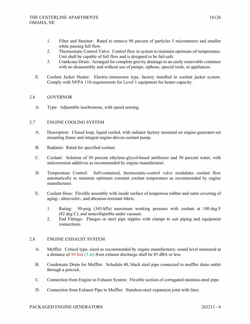
THE CENTERLINE APARTMENTS 16126
OMAHA, NE
PACKAGED ENGINE GENERATORS 263213 - 6
1. Filter and Strainer: Rated to remove 90 percent of particles 5 micrometers and smaller
while passing full flow.
2. Thermostatic Control Valve: Control flow in system to maintain optimum oil temperature.
Unit shall be capable of full flow and is designed to be fail-safe.
3. Crankcase Drain: Arranged for complete gravity drainage to an easily removable container
with no disassembly and without use of pumps, siphons, special tools, or appliances.
E. Coolant Jacket Heater: Electric-immersion type, factory installed in coolant jacket system.
Comply with NFPA 110 requirements for Level 1 equipment for heater capacity.
2.6 GOVERNOR
A. Type: Adjustable isochronous, with speed sensing.
2.7 ENGINE COOLING SYSTEM
A. Description: Closed loop, liquid cooled, with radiator factory mounted on engine-generator-set
mounting frame and integral engine-driven coolant pump.
B. Radiator: Rated for specified coolant.
C. Coolant: Solution of 50 percent ethylene-glycol-based antifreeze and 50 percent water, with
anticorrosion additives as recommended by engine manufacturer.
D. Temperature Control: Self-contained, thermostatic-control valve modulates coolant flow
automatically to maintain optimum constant coolant temperature as recommended by engine
manufacturer.
E. Coolant Hose: Flexible assembly with inside surface of nonporous rubber and outer covering of
aging-, ultraviolet-, and abrasion-resistant fabric.
1. Rating: 50-psig (345-kPa) maximum working pressure with coolant at 180 deg F
(82 deg C), and noncollapsible under vacuum.
2. End Fittings: Flanges or steel pipe nipples with clamps to suit piping and equipment
connections.
2.8 ENGINE EXHAUST SYSTEM
A. Muffler: Critical type, sized as recommended by engine manufacturer; sound level measured at
a distance of 10 feet (3 m) from exhaust discharge shall be 85 dBA or less.
B. Condensate Drain for Muffler: Schedule 40, black steel pipe connected to muffler drain outlet
through a petcock.
C. Connection from Engine to Exhaust System: Flexible section of corrugated stainless-steel pipe.
D. Connection from Exhaust Pipe to Muffler: Stainless-steel expansion joint with liner.

THE CENTERLINE APARTMENTS 16126
OMAHA, NE
PACKAGED ENGINE GENERATORS 263213 - 7
E. Exhaust Piping External to Engine: ASTM A 53/A 53M, Schedule 40, welded, black steel, with
welded joints and fittings.
2.9 COMBUSTION-AIR INTAKE
A. Description: Standard-duty, engine-mounted air cleaner with replaceable dry-filter element and
"blocked filter" indicator.
2.10 STARTING SYSTEM
A. Description: 12 or 24-V electric, with negative ground and including the following items:
1. Components: Sized so they will not be damaged during a full engine-cranking cycle with
ambient temperature at maximum specified in "Environmental Conditions" Paragraph in
"Service Conditions" Article.
2. Cranking Motor: Heavy-duty unit that automatically engages and releases from engine
flywheel without binding.
3. Cranking Cycle: As required by NFPA 110 for system level specified.
4. Battery: Adequate capacity within ambient temperature range specified in "Environmental
Conditions" Paragraph in "Service Conditions" Article to provide specified cranking cycle
at least three times without recharging.
5. Battery Cable: Size as recommended by engine manufacturer for cable length indicated.
Include required interconnecting conductors and connection accessories.
6. Battery-Charging Alternator: Factory mounted on engine with solid-state voltage
regulation and 35-A minimum continuous rating.
7. Battery Charger: Current-limiting, automatic-equalizing and float-charging type. Unit
shall comply with UL 1236 and include the following features:
a. Operation: Equalizing-charging rate of 10 A shall be initiated automatically
after battery has lost charge until an adjustable equalizing voltage is achieved
at battery terminals. Unit shall then be automatically switched to a lower
float-charging mode and shall continue to operate in that mode until battery is
discharged again.
b. Automatic Temperature Compensation: Adjust float and equalize voltages
for variations in ambient temperature from minus 40 deg C to plus 60 deg C
to prevent overcharging at high temperatures and undercharging at low
temperatures.
c. Automatic Voltage Regulation: Maintain constant output voltage regardless
of input voltage variations up to plus or minus 10 percent.
d. Ammeter and Voltmeter: Flush mounted in door. Meters shall indicate
charging rates.
e. Safety Functions: Sense abnormally low battery voltage and close contacts
providing low battery voltage indication on control and monitoring panel.
Sense high battery voltage and loss of ac input or dc output of battery charger.
Either condition shall close contacts that provide a battery-charger
malfunction indication at system control and monitoring panel.

THE CENTERLINE APARTMENTS 16126
OMAHA, NE
PACKAGED ENGINE GENERATORS 263213 - 8
f. Enclosure and Mounting: NEMA 250, Type 1, wall-mounted cabinet, within
exterior generator housing.
g. Battery Pad Heaters: Thermostatically controlled heaters arranged to
maintain battery above 10 deg C regardless of external ambient temperature
within range. Furnished with 120 volt plug in connection.
2.11 CONTROL AND MONITORING
A. Functional Description: When mode-selector switch on the control and monitoring panel is in
the automatic position, remote-control contacts in one or more separate automatic transfer
switches initiate starting and stopping of the generator set. When mode-selector switch is
switched to the on position, the generator set starts. The off position of the same switch initiates
generator-set shutdown. When generator set is running, specified system or equipment failures
or derangements automatically shut down the generator set and initiate alarms. Operation of a
remote emergency-stop switch also shuts down the generator set.
B. Configuration: Operating and safety indications, protective devices, basic system controls, and
engine gages shall be grouped in a common control and monitoring panel mounted on the
generator set. Mounting method shall isolate the control panel from generator-set vibration.
C. Indicating and protective devices and controls shall include those required by NFPA 110 for a
Level 1 system, and the following:
D. Indicating and Protective Devices and Controls:
1. Unit equipped with Control Panel with the following features
a. Microprocessor-based control of engine and alternator functions
b. Digital fault codes
c. Analog or digital display panel
d. UL 508 listed; meets NFPA 110 for level 1 systems
e. Adjustable time delay start and stop
2. Selector Switches
a. Run-Off-Auto Switch
b. Emergency Stop Switch
c. Reset Switch
d. Menu Switch
e. Voltmeter/Ammeter phase selector switch with phase and scale indicating
lamps
f. Panel lights switch, with 10 minute auto switch off
3. Display-AC Alternator Data
a. AC Voltage Line to Line
b. AC Voltage Line to Neutral
c. AC Current by Phase
d. AC Kilowatts
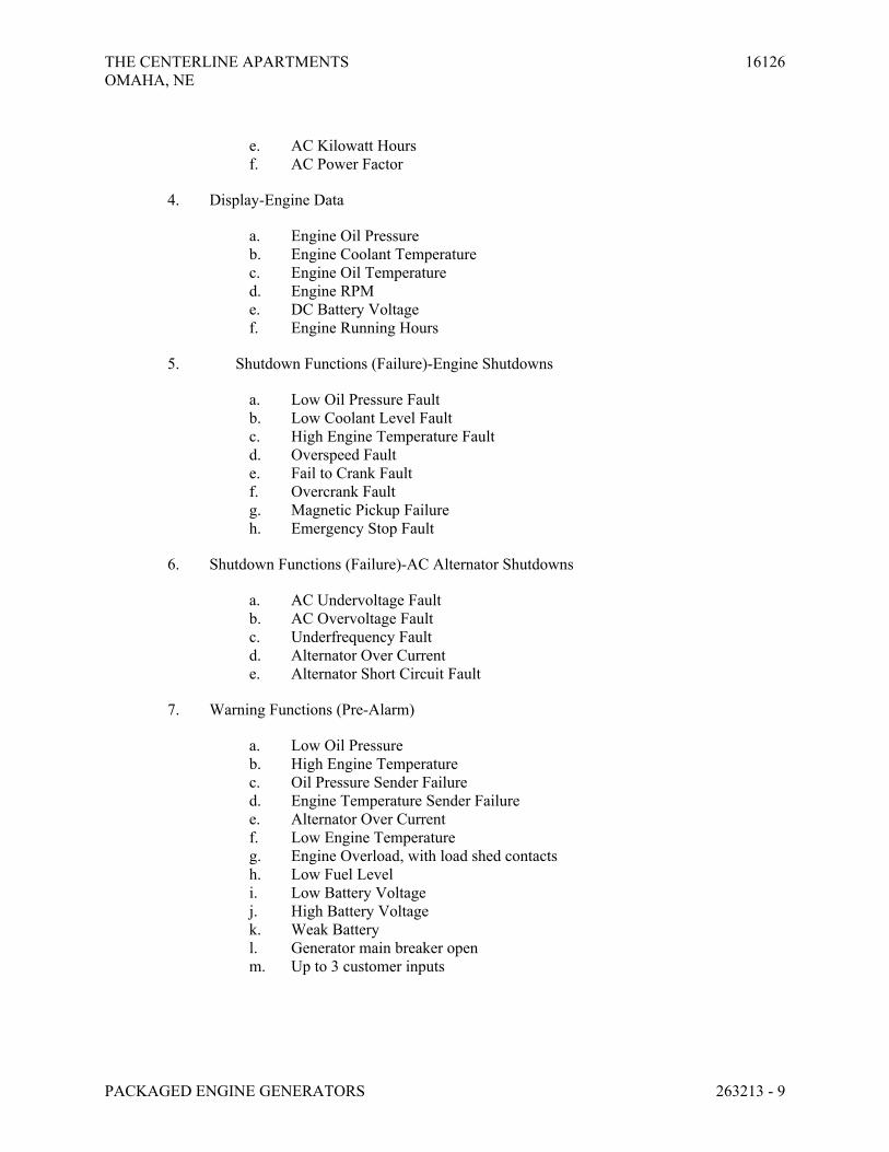
THE CENTERLINE APARTMENTS 16126
OMAHA, NE
PACKAGED ENGINE GENERATORS 263213 - 9
e. AC Kilowatt Hours
f. AC Power Factor
4. Display-Engine Data
a. Engine Oil Pressure
b. Engine Coolant Temperature
c. Engine Oil Temperature
d. Engine RPM
e. DC Battery Voltage
f. Engine Running Hours
5. Shutdown Functions (Failure)-Engine Shutdowns
a. Low Oil Pressure Fault
b. Low Coolant Level Fault
c. High Engine Temperature Fault
d. Overspeed Fault
e. Fail to Crank Fault
f. Overcrank Fault
g. Magnetic Pickup Failure
h. Emergency Stop Fault
6. Shutdown Functions (Failure)-AC Alternator Shutdowns
a. AC Undervoltage Fault
b. AC Overvoltage Fault
c. Underfrequency Fault
d. Alternator Over Current
e. Alternator Short Circuit Fault
7. Warning Functions (Pre-Alarm)
a. Low Oil Pressure
b. High Engine Temperature
c. Oil Pressure Sender Failure
d. Engine Temperature Sender Failure
e. Alternator Over Current
f. Low Engine Temperature
g. Engine Overload, with load shed contacts
h. Low Fuel Level
i. Low Battery Voltage
j. High Battery Voltage
k. Weak Battery
l. Generator main breaker open
m. Up to 3 customer inputs

THE CENTERLINE APARTMENTS 16126
OMAHA, NE
PACKAGED ENGINE GENERATORS 263213 - 10
E. Supporting Items: Include sensors, transducers, terminals, relays, and other devices and include
wiring required to support specified items. Locate sensors and other supporting items on engine
or generator, unless otherwise indicated.
F. Common Remote Audible Alarm: Comply with NFPA 110 requirements for Level 1 systems.
Include necessary contacts and terminals in control and monitoring panel.
G. Remote Annunciator Panel – NFPA 110 Solid State: NFPA-110 requirements for remote
annunciation shall be satisfied by a remote mounted solid state panel which includes a common
red indicating light and silenceable alarm horn to annunciate all alarms and shutdowns provided
by the generator set control panel when equipped with the NFPA-110 alarm module. This panel
shall include a 12 light remote annunciator.
a. Run (green)
b. Overcrank shutdown (red)
c. Overspeed shutdown (red)
d. High coolant temperature shutdown (red)
e. Low oil-pressure shutdown (red)
f. High coolant temperature pre-warning (yellow)
g. Low oil pressure pre-warning (yellow)
h. Low coolant temperature (yellow)
i. Generator set not in auto (flashing red)
j. Low fuel supply (yellow)
k. Two customer selected faults (red)
H. Remote Emergency-Stop Switch – Flush; wall mounted, unless otherwise indicated; and labeled.
Push button shall be protected from accidental operation.
2.12 GENERATOR OVERCURRENT AND FAULT PROTECTION
A. Generator Circuit Breaker: Molded-case, thermal-magnetic type; 100 percent rated; complying
with NEMA AB 1 and UL 489.
1. Tripping Characteristic: Designed specifically for generator protection.
2. Trip Rating: Matched to generator rating.
3. Shunt Trip: Battery voltage operated and connected to trip breaker when generator set is
shut down by other protective devices.
4. Mounting: Adjacent to or integrated with control and monitoring panel.
2.13 GENERATOR, EXCITER, AND VOLTAGE REGULATOR
A. Comply with NEMA MG 1 and specified performance requirements.
B. Drive: Generator shaft shall be directly connected to engine shaft. Exciter shall be rotated
integrally with generator rotor.
C. Electrical Insulation: Class H or Class F.
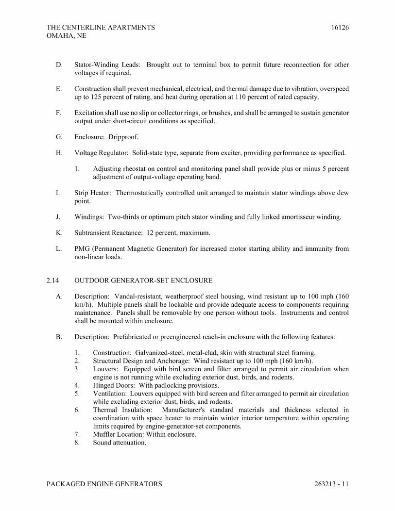
THE CENTERLINE APARTMENTS 16126
OMAHA, NE
PACKAGED ENGINE GENERATORS 263213 - 11
D. Stator-Winding Leads: Brought out to terminal box to permit future reconnection for other
voltages if required.
E. Construction shall prevent mechanical, electrical, and thermal damage due to vibration, overspeed
up to 125 percent of rating, and heat during operation at 110 percent of rated capacity.
F. Excitation shall use no slip or collector rings, or brushes, and shall be arranged to sustain generator
output under short-circuit conditions as specified.
G. Enclosure: Dripproof.
H. Voltage Regulator: Solid-state type, separate from exciter, providing performance as specified.
1. Adjusting rheostat on control and monitoring panel shall provide plus or minus 5 percent
adjustment of output-voltage operating band.
I. Strip Heater: Thermostatically controlled unit arranged to maintain stator windings above dew
point.
J. Windings: Two-thirds or optimum pitch stator winding and fully linked amortisseur winding.
K. Subtransient Reactance: 12 percent, maximum.
L. PMG (Permanent Magnetic Generator) for increased motor starting ability and immunity from
non-linear loads.
2.14 OUTDOOR GENERATOR-SET ENCLOSURE
A. Description: Vandal-resistant, weatherproof steel housing, wind resistant up to 100 mph (160
km/h). Multiple panels shall be lockable and provide adequate access to components requiring
maintenance. Panels shall be removable by one person without tools. Instruments and control
shall be mounted within enclosure.
B. Description: Prefabricated or preengineered reach-in enclosure with the following features:
1. Construction: Galvanized-steel, metal-clad, skin with structural steel framing.
2. Structural Design and Anchorage: Wind resistant up to 100 mph (160 km/h).
3. Louvers: Equipped with bird screen and filter arranged to permit air circulation when
engine is not running while excluding exterior dust, birds, and rodents.
4. Hinged Doors: With padlocking provisions.
5. Ventilation: Louvers equipped with bird screen and filter arranged to permit air circulation
while excluding exterior dust, birds, and rodents.
6. Thermal Insulation: Manufacturer's standard materials and thickness selected in
coordination with space heater to maintain winter interior temperature within operating
limits required by engine-generator-set components.
7. Muffler Location: Within enclosure.
8. Sound attenuation.
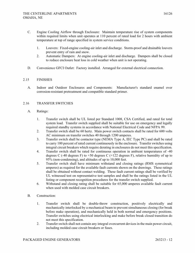
THE CENTERLINE APARTMENTS 16126
OMAHA, NE
PACKAGED ENGINE GENERATORS 263213 - 12
C. Engine Cooling Airflow through Enclosure: Maintain temperature rise of system components
within required limits when unit operates at 110 percent of rated load for 2 hours with ambient
temperature at top of range specified in system service conditions.
1. Louvers: Fixed-engine cooling-air inlet and discharge. Storm-proof and drainable louvers
prevent entry of rain and snow.
2. Automatic Dampers: At engine cooling-air inlet and discharge. Dampers shall be closed
to reduce enclosure heat loss in cold weather when unit is not operating.
D. Convenience GFCI Outlet: Factory installed. Arranged for external electrical connection.
2.15 FINISHES
A. Indoor and Outdoor Enclosures and Components: Manufacturer's standard enamel over
corrosion-resistant pretreatment and compatible standard primer.
2.16 TRANSFER SWITCHES
A. Ratings:
1. Transfer switch shall be UL listed per Standard 1008, CSA Certified, and rated for total
system load. Transfer switch supplied shall be suitable for use on emergency and legally
required standby systems in accordance with National Electrical Code and NFPA 99.
2. Transfer switch shall be 60 hertz. Main power switch contacts shall be rated for 600 volts
AC minimum on transfer switches 40 through 1200 amperes.
3. Transfer switch shall be contactor type (NEMA Type A, IEC Type PC) and shall be rated
to carry 100 percent of rated current continuously in the enclosure. Transfer switches using
integral circuit breakers which require derating in enclosures do not meet this specification.
4. Transfer switch shall be rated for continuous operation in ambient temperatures of -40
degrees C (-40 degrees F) to +50 degrees C (+122 degrees F), relative humidity of up to
95% (non-condensing), and altitudes of up to 10,000 feet.
5. Transfer switch shall have minimum withstand and closing ratings (RMS symmetrical
amperes) as required for the available fault currents shown on the drawings. These ratings
shall be obtained without contact welding. These fault current ratings shall be verified by
UL witnessed test on representative test samples and shall be the ratings listed in the UL
listing or component recognition procedures for the transfer switch supplied.
6. Withstand and closing rating shall be suitable for 65,000 amperes available fault current
when used with molded case circuit breakers.
B. Construction:
1. Transfer switch shall be double-throw construction, positively electrically and
mechanically interlocked by a mechanical beam to prevent simultaneous closing (for break
before make operation), and mechanically held in both normal and emergency positions.
Transfer switches using electrical interlocking and make before break closed transition do
not meet this specification.
2. Transfer switch shall not contain any integral overcurrent devices in the main power circuit,
including molded case circuit breakers or fuses.

THE CENTERLINE APARTMENTS 16126
OMAHA, NE
PACKAGED ENGINE GENERATORS 263213 - 13
3. Manual operating handles and all control switches shall be accessible to authorized
personnel only by opening the lockable door.
4. Transfer switch shall be equipped with direct acting linear operators for simple, reliable
and fast acting transfer during automatic operation.
5. Switch shall have cover which allows visual determination of main contact position.
6. Main switch contacts shall be high-pressure silver alloy contacts to resist burning and
pitting for long life operation. Switch shall have arc chutes of heat absorbing material and
metal leaves for positive extinguishing of arcs. Arc chutes shall have insulating covers to
prevent interphase flashover.
7. Transfer switches shall have one Form C, 10 Amp 250 Volt AC auxiliary switch on both
normal and emergency sides, operated by the transfer switch. These switches shall be
factory wired to an easy access terminal block and shall be used to monitor transfer switch
position for controlling indicator lights or other peripheral equipment.
8. Complete AL-CU lugs, UL listed and CSA certified, shall be provided for normal,
emergency, and load positions. Wiring bending space at normal, emergency, load, and
neutral lugs inside the switch cabinets shall comply with NEC Article 373.
9. Transfer switch shall be mounted in separate UL listed, NEMA 1 cabinet with key-locking
front door.
C. Automatic Controls:
1. Control shall be mounted inside of main lockable cabinet door, to allow for ease of service
access. Control disconnect plugs shall be provided to de-energize control circuits to avoid
shock hazard while making control adjustments. The solid-state voltage sensors and time
delay modules shall be plug-in circuit boards with gold contacts for ease of service. The
control shall be designed for a high level of immunity to power line surges and transients
and tested to IEEE Standard 587-1980. The control shall have optically isolated logic
inputs, high isolation transformers for AC inputs, and relays on all outputs.
2. Solid-state undervoltage sensors shall simultaneously monitor all phases of the normal
source and all phases of the emergency source to provide adjustable range sensors for field
adjustment for specific application needs. Pick-up setting shall be adjustable from
minimum of 85% to maximum of 98% of nominal voltage. Dropout settings shall be
adjustable from minimum of 75% to maximum of 98% of pick-up setting with fixed
dropout time delay of 0.5 seconds. Voltage sensors shall be temperature compensated over
the temperature range of -25 degrees F (-32 degrees C) to +175 degrees F (+79 degrees C).
Voltage sensors shall allow for adjustment to sense partial loss of voltage on any phase of
normal or emergency source, even where motor feedback voltages exist.
3. Controls shall signal the engine-generator set to start upon signal from normal source
voltage sensors. Solid-state time delay start, adjustable from 0 to 15 seconds shall avoid
nuisance start-ups on momentary voltage dips for momentary interruptions.
4. Switch shall transfer the load to the emergency power system after the generator set reaches
proper voltage and frequency. Solid-state time delay transfer, adjustable from 2 to 120
second shall allow the engine-generator set to stabilize before application of load.
5. The transfer switch shall control the generator set to allow the engine-generator set to start
and transfer load within 10 seconds after the normal source power failure. It shall be the
responsibility of the supplier of the emergency power system that this requirement is met.
6. Switch shall retransfer the load to the normal source after normal power restoration. Solid-
state time delay retransfer, adjustable from 0 to 30 minutes shall allow normal power to

THE CENTERLINE APARTMENTS 16126
OMAHA, NE
PACKAGED ENGINE GENERATORS 263213 - 14
stabilize before retransfer and shall allow staggered retransfer of loads to multiple transfer
switch systems.
7. Controls shall signal the engine-generator set to stop after load retransfer to normal source.
Solid-state time delay stop, adjustable from 0 to 10 minutes shall maintain availability of
emergency source in event that normal source fails shortly after retransfer and shall permit
engine to run unloaded for cool down before shut down.
8. The operating power for transfer and retransfer shall be obtained from the source to which
the load is being transferred. Controls shall provide an automatic retransfer of the load
from emergency source to normal source if emergency source fails when normal source is
available.
9. Controls shall provide built-in control mode status indicators, consisting of light emitting
diodes to indicate functions the following:
a. Source 1 OK
b. Start Gen Set
c. Source 2 OK
d. Transfer Timing
e. Transfer Complete
f. Retransfer Timing
g. Retransfer Complete
h. Timing for Stop
10. These indicators shall allow the operator to determine that the controls are properly
sequencing and shall assist in determining sequence of any malfunctions that might occur.
11. Start contacts for the engine control shall be gold type, dry contacts wired to easy access
terminal block and compatible with the generator set control equipment furnished.
D. Front Panel Devices:
1. Provide devices mounted inside main cabinet door consisting of switch position indicator
lamps (NORMAL and EMERGENCY), normal source available (green), emergency
source available (red), and a selector switch to provide the following positions and
functions:
a. TEST - Simulated normal power loss to control unit for testing of generator
set, including transfer of load. Controls shall provide for a system test without
load transfer. Controls shall include provisions to automatically return the
system to the normal power source if the generator set fails during any test or
exercise period.
b. NORMAL - This is a normal operating position and it restores the load to the
normal source after test and after time delays.
c. RETRANSFER - Momentary position to override retransfer time delay and
cause immediate return to normal source after test or actual outage.
E. Accessory Items:
1. Digital exercise clock installed in the transfer switch. Provide with/without load tester
switch.

THE CENTERLINE APARTMENTS 16126
OMAHA, NE
PACKAGED ENGINE GENERATORS 263213 - 15
2. Elevator pre-transfer signal relay module. Signals elevator system that transfer is pending
and delays transfer for pre-set period to prevent a power interruption during elevator
operation.
F. Transfer switch shall be provided with the following additional equipment, all installed in the
transfer switch enclosure:
1. Automatic adjustable low voltage sensors, all lines, normal side
2. Automatic adjustable low voltage sensors, all lines, emergency side
3. Automatic adjustable time delay on start, stop, transfer and retransfer
4. Manual operators
5. Program transition phase angle protection system or delayed neutral transfer position.
6. Auxiliary contacts, both normal and emergency
7. Volt, amp and frequency meters with phase selector switch, installed; meters are capable
monitoring both the normal and emergency sources when CT’s are installed on the load
side of the transfer switch
8. Phase rotation monitoring
9. Phase imbalance monitoring
10. Source available lights
11. Normal/emergency lights
PART 3 - EXECUTION
3.1 EXAMINATION
A. Examine areas, equipment bases, and conditions, with Installer present, for compliance with
requirements for installation and other conditions affecting packaged engine-generator
performance.
B. Examine roughing-in of piping systems and electrical connections. Verify actual locations of
connections before packaged engine-generator installation.
C. Proceed with installation only after unsatisfactory conditions have been corrected.
3.2 PERMITS
A. Provide all required fuel permits for the State of Nebraska and City of LaVista.
3.3 CONCRETE BASES
A. Coordinate size and location of concrete bases.
3.4 INSTALLATION

THE CENTERLINE APARTMENTS 16126
OMAHA, NE
PACKAGED ENGINE GENERATORS 263213 - 16
A. Conductors: All conductors connected to the generator shall be stranded. Use short sections of
flexible metal conduit for attachment of conduit to generator or stub up conduits in designated
conduit stub up area. Ductseal all underground conduits after conductor installation.
B. Comply with packaged engine-generator manufacturers' written installation and alignment
instructions and with NFPA 110.
C. Install packaged engine generators level on concrete base.
D. Install packaged engine generator to provide access, without removing connections or
accessories, for periodic maintenance.
E. Electrical Wiring: Install electrical devices furnished by equipment manufacturers but not
specified to be factory mounted.
3.5 CONNECTIONS
A. Tighten electrical connectors and terminals according to manufacturer's published torque-
tightening values.
B. Provide control wiring in conduit from elevator pre-transfer signal relay module within automatic
transfer switch to elevator control equipment. Verify wiring requirements with Elevator Installer.
3.6 IDENTIFICATION
A. Identify system components according to Basic Electrical Materials and Methods.
3.7 FLUID FILL
A. Electrical contractor shall provide initial fuel fill and refill system after testing is complete.
Supplier shall provide and all other fluid fills.
3.8 FIELD QUALITY CONTROL
A. Manufacturer's Field Service: Engage a factory-authorized service representative to inspect, test,
and adjust field-assembled components and equipment installation, including connections, and to
assist in field testing. Report results in writing.
B. Perform the following field tests and inspections and prepare test reports:
1. Perform tests recommended by manufacturer.
2. NFPA 110 Acceptance Tests: Perform tests required by NFPA 110.
3. Battery Tests: Equalize charging of battery cells according to manufacturer's written
instructions. Record individual cell voltages.
THE CENTERLINE APARTMENTS 16126
OMAHA, NE
PACKAGED ENGINE GENERATORS 263213 - 17
a. Measure charging voltage and voltages between available battery terminals
for full-charging and float-charging conditions. Check electrolyte level and
specific gravity under both conditions.
b. Test for contact integrity of all connectors. Perform an integrity load test and
a capacity load test for the battery.
c. Verify acceptance of charge for each element of the battery after discharge.
d. Verify that measurements are within manufacturer's specifications.
4. Battery-Charger Tests: Verify specified rates of charge for both equalizing and float-
charging conditions.
5. System Integrity Tests: Methodically verify proper installation, connection, and integrity
of each element of engine-generator system before and during system operation. Check
for air, exhaust, and fluid leaks.
6. Acceptance Load Testing:
a. The genset supplier and the Electrical Contractor shall have joint
responsibility for acceptance load testing of the emergency power generating
system. All testing will be done at the convenience of the Owner and may be
performed during non-business hours or on weekends. The Engineer shall be
notified of the test a minimum of seven (7) days prior to testing. The genset
supplier and the Electrical Contractor shall be responsible for providing as
many tests as required to demonstrate proper system operation to the
satisfaction of the Owner and Engineer.
b. The system shall be complete and ready for load testing prior to test start-up.
c. The test shall be performed through the use of resistive load banks. The load
banks shall be connected to load side of the generator control panel breaker
for testing. A minimum of 100KW of load banks shall be provided.
d. Block loading of the generation system shall be performed as follows:
Load Duration
50% 1hours
75% 1 hours
100% 2 hours
e. A recording meter shall be provided by the generator supplier to read and
provide hard copy records of the following data:
1) Transient responses including:
a) Voltage dips
b) Frequency dips
c) Recovery time period
7. At the completion of the acceptance load test, a complete building load test in compliance
with NFPA 110 shall be conducted.
a. Open transition testing: With the building load operating at normal, initiate a
power failure by disconnecting the normal power supply to the facility.
Monitor and record required test information as specified in NFPA 110 for
voltage frequency and paralleling operation. Monitor battery charge rate at 5
minute intervals for the first 15 minutes and 15 minute intervals thereafter.

THE CENTERLINE APARTMENTS 16126
OMAHA, NE
PACKAGED ENGINE GENERATORS 263213 - 18
Continue monitoring and recording load test for 2 hours noting any abnormal
resultant effects on voltage, frequency and current from load changes. After
the 2 hour running test, return normal power to the facility and record the time
delays to retransfer and engine-generator shutdown. Wait for 5 minutes after
shutdown and immediately initiate another normal power failure.
Immediately upon reaching rated frequency, apply full rated nameplate kW
(facility load with supplemental load bank if required) in one step. Record all
test data as specified earlier, operate the engine-generator at nameplate kW
for one hour noting any abnormal voltage, current or frequency changes.
System supplier shall provide lube oil, 50% solution of ethylene glycol, initial
fill of diesel fuel and refill of fuel after test.
b. Utility paralleling test (To be witnessed by engineer and power company):
With the building load operating at normal, initiate the starting of the
generator, and parallel with utility and export power to utility grid Monitor
and record required test information as specified in NFPA 110 for voltage
frequency and paralleling operation. Monitor battery charge rate at 5 minute
intervals for the first 15 minutes and 15 minute intervals thereafter. Continue
monitoring and recording load test for 2 hours noting any abnormal resultant
effects on voltage, frequency and current from load changes. After the 2 hour
running test, return normal power to the facility and record the time delays to
retransfer and engine-generator shutdown. Record all test data as specified
earlier, operate the engine-generator at nameplate kW for one hour noting any
abnormal voltage, current or frequency changes. System supplier shall
provide lube oil, 50% solution of ethylene glycol, initial fill of diesel fuel and
refill of fuel after test.
8. Test reports shall be submitted to the Engineer and shall be included with the operations
and maintenance manuals.
C. Coordinate tests with tests for transfer switches and run them concurrently.
D. Test and adjust controls and safeties. Replace damaged and malfunctioning controls and
equipment.
E. Retest: Correct deficiencies identified by tests and observations and retest until specified
requirements are met.
F. Report results of tests and inspections in writing. Record adjustable relay settings and measured
insulation resistances, time delays, and other values and observations. Attach a label or tag to
each tested component indicating satisfactory completion of tests.
3.9 STARTUP SERVICE
A. Engage a factory-authorized service representative to perform startup service.
B. Inspect field-assembled components and equipment installation, including piping and electrical
connections. Report results in writing.
C. Complete installation and startup checks according to manufacturer's written instructions.
THE CENTERLINE APARTMENTS 16126
OMAHA, NE
PACKAGED ENGINE GENERATORS 263213 - 19
3.10 DEMONSTRATION
A. Engage a factory-authorized service representative to train Owner's maintenance personnel to
adjust, operate, and maintain packaged engine generators.
1. Coordinate this training with that for transfer switches.
2. Train Owner's maintenance personnel on procedures and schedules for starting and
stopping, troubleshooting, servicing, and maintaining equipment.
3. Review data in maintenance manuals.
4. Schedule training with Owner, through Engineer, with at least seven days' advance notice.
5. Instruction Period: After the test is completed, the supplier shall provide four (4), one (1)
hour classes to the owner pertaining to general maintenance inspection and testing of the
entire system.
6. Video Recording: Video record training sessions for future use by the Owner.
END OF SECTION 263213

THE CENTERLINE APARTMENTS 16126
OMAHA, NE
SURGE PROTECTIVE DEVICES (SPD'S) 264313 - 1
SECTION 264313 – SURGE PROTECTIVE DEVICES (SPD’S)
PART 1 - GENERAL
1.1 RELATED DOCUMENTS
A. Drawings and general provisions of the Contract, including General and Supplementary
Conditions and Division 01 Specification Sections, apply to this Section.
1.2 SUMMARY
A. Section includes permanently installed, factory or field mounted, 1kV or less surge protective
device (SPD) equipment.
1.3 DEFINITIONS
A. Type 2 SPD: Referred to as hardwired transient voltage surge suppressors (TVSS) prior to the
2008 NEC. These devices are designed for installation at any location on the load side of the
service disconnect. External overcurrent protection is allowed.
B. Type 4 SPD: SPD components intended to be part of a complete SPD.
C. VPR: Voltage protection rating.
1.4 ACTION SUBMITTALS
A. Product Data: For each type of product indicated. Include rated capacities, operating weights,
electrical characteristics, furnished specialties, and accessories.
1.5 CLOSEOUT SUBMITTALS
A. Operation and Maintenance Data: For SPD devices to include in emergency, operation, and
maintenance manuals.
1.6 QUALITY ASSURANCE
A. Electrical Components, Devices, and Accessories: Listed and labeled as defined in NFPA 70, by
a testing agency, and marked for intended location and application.
B. Comply with IEEE C62.41.2 and test devices according to IEEE C62.45.

THE CENTERLINE APARTMENTS 16126
OMAHA, NE
SURGE PROTECTIVE DEVICES (SPD'S) 264313 - 2
C. Comply with UL 1449 3rd Edition.
D. Comply with NFPA 70, 2008 Edition.
1.7 PROJECT CONDITIONS
A. Service Conditions: Rate SPDs for continuous operation under the following conditions unless
otherwise indicated:
1. Maximum Continuous Operating Voltage: Not less than 125 percent of nominal system
operating voltage.
2. Operating Temperature: 30 to 120 deg F.
3. Humidity: 0 to 85 percent, noncondensing.
4. Altitude: Less than 20,000 feet above sea level.
1.8 WARRANTY
A. Special Warranty: Manufacturer's standard form in which manufacturer agrees to repair or
replace components of surge suppressors that fail in materials or workmanship within specified
warranty period.
1. Warranty Period: Ten years from date of Substantial Completion.
PART 2 - PRODUCTS
2.1 MANUFACTURERS
A. Designed for integration into selected switchgear/switchboard/panelboard manufacturer’s
equipment.
1. Panel arrangement allowing maximum lead length to phase, neutral, and ground bus
connection points of 8”.
B. Subject to compliance with requirements, provide product by one of the following:
1. Cutler-Hammer; Eaton Business Unit.
2. GE Zenith.
3. Siemens.
4. Surgelogic/Square D; Schneider Electric Business Unit.
C. SPD for Service Entrance Equipment Location (Primary Protection)
1. UL listed to UL 1449 3rd Edition
2. Type 1 (installed downstream of main breaker) or Type 2.
3. 20kA nominal discharge (In).
THE CENTERLINE APARTMENTS 16126
OMAHA, NE
SURGE PROTECTIVE DEVICES (SPD'S) 264313 - 3
4. Short-circuit current rating (SCCR) complying with UL 1449, and matching or exceeding
the connected equipment short-circuit rating.
5. 7 modes of protection (L-N, L-G, N-G).
6. Peak surge current rating: 200kA per phase.
7. VPR: Not to exceed 700V for 208Y/120V systems.
8. System voltage: match service entrance equipment.
9. EMI/RFI noise rejection filter: Noise attenuation of 50 dB from 10 kHz to 100 MHz using
the MIL-STD-220A insertion loss test method.
10. LED indicator lights for power and protection status.
11. Audible alarm, with silencing switch, to indicate when protection has failed.
12. Form-C contacts rated at 5 A and 250-V ac, one normally open and one normally closed,
for remote monitoring of protection status. Contacts shall reverse on failure of any surge
diversion module or on opening of any current-limiting device. Coordinate with building
power monitoring and control system.
13. Six-digit transient-event counter set to totalize transient surges.
D. SPDs for Non-Service Entrance Equipment Locations (Secondary Protection)
1. UL listed to UL 1449 3rd Edition
2. Type 1 (installed downstream of main breaker) or Type 2.
3. 20kA nominal discharge (In).
4. Short-circuit current rating (SCCR) complying with UL 1449, and matching or exceeding
the connected equipment short-circuit rating and.
5. 7 modes of protection (L-N, L-G, N-G).
6. Peak surge current rating: 100kA per phase.
7. VPR: Not to exceed 700V for 208Y/120V systems.
8. System voltage: match connected equipment.
9. EMI/RFI noise rejection filter: Noise attenuation of 50 dB from 10 kHz to 100 MHz using
the MIL-STD-220A insertion loss test method.
10. LED indicator lights for power and protection status.
11. Audible alarm, with silencing switch, to indicate when protection has failed.
12. Form-C contacts rated at 5 A and 250-V ac, one normally open and one normally closed,
for remote monitoring of protection status. Contacts shall reverse on failure of any surge
diversion module or on opening of any current-limiting device. Coordinate with building
power monitoring and control system.
2.2 ENCLOSURES
A. Indoor Enclosures: NEMA 250.
PART 3 - EXECUTION
3.1 INSTALLATION
A. Install SPD devices at service entrance on load side of main disconnect, with ground lead bonded
to service entrance ground.

THE CENTERLINE APARTMENTS 16126
OMAHA, NE
SURGE PROTECTIVE DEVICES (SPD'S) 264313 - 4
B. Install SPD devices for panelboards and auxiliary panels with conductors or buses between
suppressor and points of attachment as short and straight as possible. Do not exceed
manufacturer's recommended lead length. Do not bond neutral and ground.
1. Comply with manufacturer's written recommendation for conductor and circuit-breaker
size for connecting SPD devices to distribution system.
C. Tests and Inspections:
1. Perform each visual and mechanical inspection and electrical test stated in NETA ATS,
"Surge Arresters, Low-Voltage Surge Protection Devices" Section. Certify compliance
with test parameters.
2. After installing SPD devices but before electrical circuitry has been energized, test for
compliance with requirements.
3. Complete startup checks according to manufacturer's written instructions.
4. Coordinate with commissioning agent. Supply requested product documentation.
D. SPD device will be considered defective if it does not pass tests and inspections.
E. Prepare test and inspection reports.
3.2 STARTUP SERVICE
A. Do not energize or connect to their sources until SPDs are installed and connected.
B. Do not perform insulation resistance tests of the distribution wiring equipment with the SPD
installed. Disconnect before conducting insulation resistance tests, and reconnect immediately
after the testing is over.
3.3 DEMONSTRATION
A. Train Owner's maintenance personnel to maintain SPD devices.
END OF SECTION 264313

THE CENTERLINE APARTMENTS 16126
OMAHA, NE
LIGHTING 265100 - 1
SECTION 265100 – LIGHTING
PART 1 - GENERAL
1.1 RELATED DOCUMENTS
A. Drawings and general provisions of the Contract, including General and Supplementary
Conditions and Division 1 Specification Sections, apply to this Section.
1.2 SUMMARY
A. This Section includes lighting fixtures, lighting controls, lighting fixtures mounted on exterior
building surfaces, exterior lighting, lamps, ballasts, emergency lighting units, emergency
fluorescent power supply units, and accessories.
1.3 SUBMITTALS
A. Product Data: For each lighting fixture type, arranged in order of fixture designation. Include
data on features, accessories, and the following:
1. Dimensions of fixtures.
2. Emergency lighting unit battery and charger.
B. Product Data: For each type of lighting control.
C. Occupancy Sensor Layout Drawings: Scaled floor plans with lighting control manufacturer’s
layout of occupancy sensors. Sensor layout and quantity shall completely cover each area
indicated, show coverage patterns for each sensor.
D. Maintenance Data: For lighting fixtures to include in maintenance manuals specified in
Division 1.
1.4 QUALITY ASSURANCE
A. Fixtures Emergency Lighting Units, Emergency Fluorescent Power Supply Units, and
Accessories: Listed and labeled as defined in NFPA 70, Article 100, by a testing agency
acceptable to authorities having jurisdiction.
B. Comply with NFPA 70.
C. NFPA 101 Compliance: Comply with visibility and luminance requirements for exit signs.

THE CENTERLINE APARTMENTS 16126
OMAHA, NE
LIGHTING 265100 - 2
1.5 COORDINATION
A. Fixtures, Mounting Hardware, and Trim: Coordinate layout and installation of lighting fixtures
with ceiling system and other construction.
1.6 WARRANTY
A. Emergency Battery Warranty: 3-year pro-rated warranty.
B. LED Driver/ Light System Warranty: 5-year replacement warranty.
1.7 EXTRA MATERIALS
A. Furnish extra materials described below that match products installed and that are packaged with
protective covering for storage and identified with labels describing contents.
1. Lamps: 10 for every 100 of each type and rating installed. Furnish at least one of each
type.
2. LED Driver/System: Provide 5 for every 100 of each type and rating installed. Furnish at
least two of each type.
PART 2 - PRODUCTS
2.1 MANUFACTURERS
A. Products: Subject to compliance with requirements, provide one of the products indicated for
each designation in the Lighting Fixture Schedules on the drawings.
2.2 FIXTURES AND FIXTURE COMPONENTS, GENERAL
A. Metal Parts: Free from burrs, sharp corners, and edges.
B. Sheet Metal Components: Steel, unless otherwise indicated. Form and support to prevent
warping and sagging.
C. Doors, Frames, and Other Internal Access: Smooth operating, free from light leakage under
operating conditions, and arranged to permit relamping without use of tools. Arrange doors,
frames, lenses, diffusers, and other pieces to prevent accidental falling during relamping and when
secured in operating position.
D. Reflecting Surfaces: Minimum reflectance as follows, unless otherwise indicated:
1. White Surfaces: 85 percent.
2. Specular Surfaces: 83 percent.
3. Diffusing Specular Surfaces: 75 percent.
THE CENTERLINE APARTMENTS 16126
OMAHA, NE
LIGHTING 265100 - 3
4. Laminated Silver Metallized Film: 90 percent.
E. Lenses, Diffusers, Covers, and Globes: 100 percent virgin acrylic plastic or annealed crystal
glass, unless otherwise indicated.
1. Plastic: High resistance to yellowing and other changes due to aging, exposure to heat, and
ultraviolet radiation.
2. Lens Thickness: 0.125 inch (3 mm) minimum, unless greater thickness is indicated.
2.3 LED DRIVERS
A. General Requirements: Unless otherwise indicated, features include the following:
1. 0-10V Dimming
2. Total Harmonic Distortion Rating: Less than 20 percent.
3. Ambient temperature rating: -40° to +55° C
4. Power Factor (100% output): >0.95
2.4 EXIT SIGNS
A. General Requirements: Comply with UL 924 and the following:
1. Sign Colors and Lettering Size: Comply with authorities having jurisdiction.
B. Internally Lighted Signs: As follows:
1. Lamps for AC Operation: Light-emitting diodes, 70,000 hours minimum rated lamp life.
2.5 EMERGENCY LIGHTING UNITS
A. General Requirements: Self-contained units, wall or ceiling mounted. Comply with UL 924.
Units include the following features:
1. Battery: Sealed, maintenance-free, lead-acid type with minimum 5-year nominal life and
warranty.
2. Charger: Fully automatic, solid-state type with sealed transfer relay.
3. Operation: Relay automatically turns lamp on when supply circuit voltage drops to 80
percent of nominal voltage or below. Lamp automatically disconnects from battery when
voltage approaches deep-discharge level. When normal voltage is restored, relay
disconnects lamps, and battery is automatically recharged and floated on charger.
2.6 LED LIGHT MODULE
A. General Requirements: Unless otherwise indicated, features include the following:

THE CENTERLINE APARTMENTS 16126
OMAHA, NE
LIGHTING 265100 - 4
1. L70 (70% light output) life rating: minimum 50,000 hours, as defined by IES LM80 and
TM21
2. Minimum Color-Rendering Index: 80 CRI
2.7 FIXTURE SUPPORT COMPONENTS
A. Comply with Division 26 Section "Basic Electrical Materials and Methods," for channel- and
angle-iron supports and nonmetallic channel and angle supports.
B. Twin-Stem Hangers: Two, 1/2-inch (12-mm) steel tubes with single canopy arranged to mount a
single fixture. Finish same as fixture.
C. Rod Hangers: 3/8-inch minimum diameter, cadmium-plated, threaded steel rod.
2.8 FINISHES
A. Fixtures: Manufacturer's standard, unless otherwise indicated.
1. Paint Finish: Applied over corrosion-resistant treatment or primer, free of defects.
2. Metallic Finish: Corrosion resistant.
PART 3 - EXECUTION
3.1 INSTALLATION
A. Fixtures: Set level, plumb, and square with ceiling and walls, and secure according to
manufacturer's written instructions and approved submittal materials. Install lamps in each
fixture.
B. Support for Fixtures in or on Grid-Type Suspended Ceilings: Use grid for support.
1. Install a minimum of two ceiling support system rods or wires for each fixture. Locate not
more than 6 inches (150 mm) from fixture corners.
2. Support Clips: Fasten to fixtures and to ceiling grid members at or near each fixture corner.
3. Fixtures of Sizes Less Than Ceiling Grid: Arrange as indicated on reflected ceiling plans
or center in acoustical panel, and support fixtures independently with at least two 3/4-inch
(20-mm) metal channels spanning and secured to ceiling tees.
C. Suspended Fixture Support: As follows:
1. Pendants and Rods: Where longer than 48 inches (1200 mm), brace to limit swinging.
2. Continuous Rows: Suspend from cable installed according to fixture manufacturer's
written instructions and details on Drawings.
D. Burn-In: Continuously illuminate (burn-in) lamps and fixtures per lamp manufacturer’s
recommendations.

THE CENTERLINE APARTMENTS 16126
OMAHA, NE
LIGHTING 265100 - 5
3.2 CONNECTIONS
A. Ground equipment.
1. Tighten electrical connectors and terminals according to manufacturer's published torque-
tightening values.
3.3 FIELD QUALITY CONTROL
A. Inspect each installed fixture for damage. Replace damaged fixtures and components.
B. Provide instruments to make and record test results.
C. Tests: As follows:
1. Verify normal operation of each fixture after installation.
2. Emergency Lighting: Interrupt electrical supply to demonstrate proper operation.
3. Verify normal transfer to battery source and retransfer to normal.
4. Malfunctioning Fixtures and Components: Replace or repair, then retest. Repeat
procedure until units operate properly.
3.4 CLEANING AND ADJUSTING
A. Clean fixtures internally and externally after installation. Use methods and materials
recommended by manufacturer.
B. Adjust aimable fixtures to provide required light intensities.
END OF SECTION 265100
THE CENTERLINE APARTMENTS 16126
OMAHA, NE
LIGHTING CONTROL 265200 - 1
SECTION 265200 – LIGHTING CONTROL
PART 1 - GENERAL
1.1 RELATED DOCUMENTS
A. Drawings and general provisions of the Contract, including General and Supplementary
Conditions and Division 1 Specification Sections, apply to this Section.
1.2 SUMMARY
A. This Section includes lighting control panels, lighting control devices, and accessories.
B. Related Requirements:
1. See section 262726 "Wiring Devices" for wall-box dimmers and manual light switches.
1.3 SUBMITTALS
A. Product Data: For each lighting control panel and device. Include data on features, accessories,
and the following:
1. Lighting control panels and devices.
2. Dimensions of control panels and devices.
3. Lighting control system one line diagram.
B. Occupancy Sensor Layout Drawings: Scaled floor plans with lighting control manufacturer’s
layout of occupancy sensors. Sensor layout and quantity shall completely cover each area
indicated, show coverage patterns for each sensor.
C. Maintenance Data: For lighting control panels and devices to include in maintenance manuals
specified in Division 1.
1.4 QUALITY ASSURANCE
A. Listed and labeled as defined in NFPA 70, Article 100, by a testing agency acceptable to
authorities having jurisdiction.
B. Comply with NFPA 70.
PART 2 - PRODUCTS
THE CENTERLINE APARTMENTS 16126
OMAHA, NE
LIGHTING CONTROL 265200 - 2
2.1 MANUFACTURERS
A. Lighting Control Equipment: Subject to compliance with requirements, provide lighting control
equipment from one of the following manufacturers, all equipment should be from one consistent
manufacturer:
1. Sensor Switch / Lighting Control & Design (LC&D)
2. Hubbell Building Automation
3. WattStopper
2.2 RELAY PANELS:
A. NEMA 1 rated enclosure with screw cover or hinged door. Other NEMA types per drawings.
B. 16 AWG steel barrier shall separate the high voltage and low voltage compartments of the panel
and separate 120v and 277v.
C. LCP input power shall be capable of accepting 120v or 277v without rewiring
D. Control electronics in the low voltage section shall be capable of driving 2 to 48, 30a, 14,000
SCCR rated latching relays, control any individual or group of relays, provide individual relay
overrides, provide a master override for each panel, store all programming in non-volatile
memory, after power is restored return system to current state, provide programmable blink warn
timers for each relay and every zone, and be able to control relays that default to Open, Normally
Open Latching (NOL) or relays that default to Closed, Normally Closed Latching (NCL).
E. NC Relays shall be UL924 listed for use as an emergency lighting switching device. If NC relays
are not UL924 listed provide UL924 switch bypass devices as necessary to bypass relays serving
to life safety circuits.
F. Control electronics shall include a dial-up modem with free lifetime dial-up factory programming.
G. Lighting control system shall be digital and consist of a Master LCP, Slave LCPs, Micro LCPs
with up to 8 individual relays, digital switches, and digital interface cards. All system components
shall connect and be controlled via a single Category 5, 4 twisted pair cable with RJ45 connectors,
providing real time two-way communication with each system component. Analog systems are
not acceptable.
H. LC&D, GR2400 series.
2.3 DIGITAL ENTRY STATIONS
A. Device, button, and faceplate color shall match other electrical devices per division 26 "Wiring
Devices".
B. Provide with quantity of buttons per drawings.

THE CENTERLINE APARTMENTS 16126
OMAHA, NE
LIGHTING CONTROL 265200 - 3
C. Provide permanent factory applied or engraved labels. Coordinate labels with Engineer/Owner
prior to ordering.
D. Entry stations shall communicate with lighting system controller digitally via cat 5 with RJ45
connectors.
E. LC&D, Chelsea Digital Switch.
2.4 LIGHTING CONTROL SYSTEM CABLING
A. Provide J-Hook style supports for low voltage cabling above accessible ceilings. Where exposed
structure occurs run low voltage cabling concealed in conduit.
B. Provide plenum rated pre-terminated low voltage cabling as manufactured by lighting control
manufacturer. Provide lengths necessary for installation, cables shall be as short as practical with
a minimum 10' cable length.
2.5 OCCUPANCY SENSORS
A. Low Voltage Ceiling Sensors:
1. Passive Dual Technology: Infrared and microphonic sensors integrated into one housing.
2. Performance and Coverage: Passive Infrared (PIR) shall engage sensor and PIR or
microphonic shall detect continued occupancy. 360 degree field of view. Minimum
coverage of 20 foot radius at 9' mounting height, with sensor centered in coverage area.
Provide accessory power packs and connect to power sensor.
3. Mounting: Sensor shall flush horizontal mount tight to ceiling surface. Sensors that
protrude from ceiling or utilize drop-down mounting brackets shall not be acceptable.
4. Finish: White.
5. Load Rating: Provide accessory power packs with relay; connect to switch load. Relay in
power packs shall be rated 20A for ballast loads.
6. Sensor Switch CM PDT 10 or approved equivalent. Provide associated power packs with
sensor power supply and load switching relay.
B. Line Voltage Single Pole Wall Box Sensors:
1. Passive Dual Technology: Infrared and microphonic sensors integrated into one housing.
2. Performance and Coverage: Passive Infrared (PIR) shall engage sensor and PIR or
microphonic shall detect continued occupancy. 180 degree field of view. Capable of
sensing small motion up to 20' at 4' mounting height.
3. On Modes
a. Automatic on - Sensor turns load on based on sensing occupancy of monitored
area.
b. Manual on - sensor requires pressing the pushbutton on sensor face to turn
load on.

THE CENTERLINE APARTMENTS 16126
OMAHA, NE
LIGHTING CONTROL 265200 - 4
c. Reduced turn on - sensor automatically turns load on with detection of large
motion, automatically switches minor motion detection on after load is
initially powered on.
4. Switch Off Modes
a. Predictive off mode - occupant can turn lights off manually or lights
automatically turn off after time out period. If lights are manually turned off,
the sensor shall revert to automatic on after sensor sees no motion during time
out period.
b. Permanent off mode - pressing the switch turns the lights off, lights will not
turn on until switch is pressed again.
c. Switch disable - prevents user from manually turning lights off.
5. Mounting: Sensor shall mount in wall box with decorator style faceplate.
6. Load Rating: Switch integral in sensor housing
a. Rated for 800 watt ballast or incandescent load at 120V
b. Rated for ¼ horsepower motor load at 120V
7. Sensor Switch WSD PDT or approved equivalent.
8. Passive Dual Technology: Infrared and microphonic sensors integrated into one housing.
9. Performance and Coverage: Passive Infrared (PIR) shall engage sensor and PIR or
microphonic shall detect continued occupancy. 120 degree field of view. Minimum
coverage of 40' minor motion detection at 8' mounting height, with sensor at center of field
of view. Provide accessory power packs and connect to power sensor.
10. Mounting: Sensor shall flush horizontal mount tight to ceiling surface. Sensors that
protrude from ceiling or utilize drop-down mounting brackets shall not be acceptable.
11. Finish: White.
12. Load Rating: Provide accessory power packs with relay; connect to switch load. Relay in
power packs shall be rated 20A for ballast loads.
13. Sensor Switch WV PDT 16 or approved equivalent. Provide associated power packs with
sensor power supply and load switching relay.
PART 3 - EXECUTION
3.1 INSTALLATION
A. Coordinate layout and installation of ceiling-mounted devices with other construction that
penetrates ceilings or is supported by them, including light fixtures, HVAC equipment, smoke
detectors, fire-suppression systems, and partition assemblies.
B. Occupancy Sensors: Provide required power packs with sensor power supply and load switching
relay. Connect power packs per manufacturer’s instructions. Adjust settings of occupancy
sensors, tailor to configuration and use of room served.
C. After Substantial Completion, but not more than 60 days after Final Acceptance, re-adjust
occupancy sensors for Owner’s actual pattern of use.

THE CENTERLINE APARTMENTS 16126
OMAHA, NE
LIGHTING CONTROL 265200 - 5
3.2 FIELD QUALITY CONTROL
A. Tests: As follows:
1. Verify normal operation of each lighting control per lighting control sequence of
operations.
B. Malfunctioning Lighting Controls: Replace or repair, then retest. Repeat procedure until units
operate properly.
C. Prepare test and inspection reports.
3.3 ADJUSTING
A. Occupancy Adjustments: When requested within 12 months from date of Substantial
Completion, provide on-site assistance in adjusting sensors to suit actual occupied conditions.
Provide up to two visits to Project during other-than-normal occupancy hours for this purpose.
1. For occupancy and motion sensors, verify operation at outer limits of detector range. Set
time delay to suit Owner's operations.
2. For daylighting controls, adjust set points and deadband controls to suit Owner's
operations.
3.4 DEMONSTRATION
A. Train Owner's maintenance personnel to adjust, operate, and maintain lighting control devices.
END OF SECTION 265200
THE CENTERLINE APARTMENTS 16126
OMAHA, NE
FIRE ALARM 268100 - 1
SECTION 268100 – FIRE ALARM
PART 1 - GENERAL
1.1 RELATED DOCUMENTS
A. Drawings and general provisions of the Contract, including General and Supplementary
Conditions and Division 1 Specification Sections, apply to this Section.
1.2 SUMMARY
A. This Section includes fire alarm systems with control panel, manual stations, detectors, signal
equipment, controls, and devices.
B. FACP: Fire alarm control panel.
C. LED: Light-emitting diode.
D. Definitions in NFPA 72 apply to fire alarm terms used in this Section.
1.3 SYSTEM DESCRIPTION
A. General: Noncoded, analog-addressable system; and multiplexed signal transmission dedicated
to fire alarm service only.
1.4 SUBMITTALS
A. Product Data: For each type of product indicated.
B. Shop Drawings:
1. Drawings: Prepare project specific information, drawn accurately to scale. Do not base
Shop Drawings on reproductions of the Contract Documents or standard printed media.
2. Wiring Diagrams: Detail wiring and differentiate between manufacturer-installed and
field-installed wiring. Include diagrams for equipment and for system with all terminals
and interconnections identified.
C. Operating Instructions: For mounting at the FACP.
D. Submissions to Authorities Having Jurisdiction: Submit to authorities having jurisdiction.
Include copies of annotated Contract Drawings as needed to depict component locations to
facilitate review. Resubmit if required to make clarifications or revisions to obtain approval. On
receipt of comments from authorities having jurisdiction, submit them to Engineer for review.

THE CENTERLINE APARTMENTS 16126
OMAHA, NE
FIRE ALARM 268100 - 2
E. Certificate of Completion: Comply with NFPA 72.
1.5 QUALITY ASSURANCE
A. Installer Qualifications: An experienced installer who is an authorized representative of the
FACP manufacturer for both installation and maintenance of units required for this Project.
B. Manufacturer Qualifications: A firm experienced in manufacturing systems similar to those
indicated for this Project and with a record of successful in-service performance.
C. Source Limitations: Obtain fire alarm system components through one source from a single
manufacturer.
D. Compliance with Local Requirements: Comply with applicable building code, local ordinances
and regulations, and requirements of authorities having jurisdiction.
E. Comply with NFPA 72.
1.6 EXTRA MATERIALS
A. Furnish extra materials described below that match products installed and that are packaged with
protective covering for storage and identified with labels describing contents.
1. Lamps for Remote Indicating Lamp Units: Quantity equal to 10 percent of amount
installed, but not less than 1 unit.
2. Lamps for Strobe Units: Quantity equal to 10 percent of amount installed, but not less than
1 unit.
3. Smoke, Fire, and Flame Detectors: Quantity equal to 10 percent of amount of each type
installed, but not less than 1 unit of each type.
4. Detector Bases: Quantity equal to 2 percent of amount of each type installed, but not less
than 1 unit of each type.
5. Keys and Tools: One extra set for access to locked and tamperproofed components.
6. Audible and Visual Notification Appliances: One of each type installed.
7. Fuses: Two of each type installed in the system.
PART 2 - PRODUCTS
2.1 MANUFACTURERS
A. Manufacturers: Subject to compliance with requirements, provide products by one of the
following:
1. Cerberus Pyrotronics.
2. Notifier; Div. of Pittway Corp.
3. Edwards Systems Technology; Unit of General Signal.
4. Fire Lite Alarms, Inc.

THE CENTERLINE APARTMENTS 16126
OMAHA, NE
FIRE ALARM 268100 - 3
5. Fire Control Instruments
6. Silent Knight
2.2 PERFORMANCE REQUIREMENTS
A. Comply with NFPA 72.
B. Premises protection includes type 1A and 5A construction, and type R-2, B, and S-2 occupancies.
C. Fire alarm signal initiation shall be by one or more of the following devices:
1. Manual stations.
2. Heat detectors.
3. Smoke detectors.
4. Automatic sprinkler system water flow.
D. Fire alarm signal shall initiate the following actions:
1. Alarm notification appliances shall operate continuously.
2. Identify alarm at the FACP and remote annunciators.
3. De-energize electromagnetic door holders.
4. Transmit an alarm signal to the remote alarm receiving station.
5. Unlocking of electric door locks in designated egress paths.
6. Release of fire and smoke doors held open by magnetic door holders if alarm was initiated
by a detector on either side of the door.
7. Recall of elevators if alarm was initiated by a detector at elevator lobby, elevator shaft, or
elevator machine room.
8. Shutdown of fans and other air-handling equipment serving zone where alarm was
initiated.
9. Closing of smoke dampers in air ducts of system serving zone where alarm was initiated
by opening a fire alarm relay to interrupt power to smoke dampers located in air supply
ducts across smoke partitions in the area of the alarm.
10. Record events in the system memory.
E. Supervisory signal initiation shall be by one or more of the following devices or actions:
1. Operation of a fire-protection system valve tamper.
F. System trouble signal initiation shall be by one or more of the following devices or actions:
1. Open circuits, shorts and grounds of wiring for initiating device, signaling line, and
notification-appliance circuits.
2. Opening, tampering, or removal of alarm-initiating and supervisory signal-initiating
devices.
3. Loss of primary power at the FACP.
4. Ground or a single break in FACP internal circuits.
5. Abnormal ac voltage at the FACP.
6. A break in standby battery circuitry.
7. Failure of battery charging.

THE CENTERLINE APARTMENTS 16126
OMAHA, NE
FIRE ALARM 268100 - 4
8. Abnormal position of any switch at the FACP or annunciator.
G. System Trouble and Supervisory Signal Actions: Ring trouble bell and annunciate at the
FACP and remote annunciators. Record the event on system printer.
H. Elevator Controls: Operation of a heat detector in elevator shaft or machine room shuts down
elevator power by operating a shunt trip in a circuit breaker feeding the elevator.
2.3 MANUAL PULL STATIONS
A. Description: Fabricated of metal or plastic, and finished in red or brushed aluminum with molded
operating instructions of contrasting color.
1. Single-action mechanism initiates an alarm. With integral addressable module, arranged to
communicate manual-station status (normal, alarm, or trouble) to the FACP.
2. Station Reset: Key or wrench operated.
2.4 SMOKE DETECTORS
A. General Description:
1. UL 268 listed, operating at 24-V dc, nominal.
2. Integral Addressable Module: Arranged to communicate detector status (normal, alarm,
or trouble) to the FACP.
3. Plug-in Arrangement: Detector and associated electronic components shall be mounted in
a plug-in module that connects to a fixed base. Provide terminals in the fixed base for
connection of building wiring.
4. Self-Restoring: Detectors do not require resetting or readjustment after actuation to restore
them to normal operation.
5. Integral Visual-Indicating Light: LED type. Indicating and power-on status.
B. Photoelectric Smoke Detectors:
1. Detector style: Low Profile.
2. Sensor: LED or infrared light source with matching silicon-cell receiver.
3. Detector Sensitivity: Between 2.5 and 3.5 percent/foot smoke obscuration when tested
according to UL 268A.
C. Duct Smoke Detectors:
1. Photoelectric Smoke Detectors:
a. Sensor: LED or infrared light source with matching silicon-cell receiver.
b. Detector Sensitivity: Between 2.5 and 3.5 percent/foot smoke obscuration
when tested according to UL 268A.
2. UL 268A listed, operating at 24-V dc, nominal.

THE CENTERLINE APARTMENTS 16126
OMAHA, NE
FIRE ALARM 268100 - 5
3. Integral Addressable Module: Arranged to communicate detector status (normal, alarm,
or trouble) to the FACP.
4. Plug-in Arrangement: Detector and associated electronic components shall be mounted in
a plug-in module that connects to a fixed base. The fixed base shall be designed for
mounting directly to the air duct. Provide terminals in the fixed base for connection to
building wiring.
5. Self-Restoring: Detectors shall not require resetting or readjustment after actuation to
restore them to normal operation.
6. Integral Visual-Indicating Light: LED type. Indicating and power-on status.
7. Remote Control: Unless otherwise indicated, detectors shall be analog-addressable type,
individually monitored at the FACP for calibration, sensitivity, and alarm condition, and
individually adjustable for sensitivity from the FACP.
8. Each sensor shall have multiple levels of detection sensitivity.
9. Sampling Tubes: Design and dimensions as recommended by manufacturer for the specific
duct size, air velocity, and installation conditions where applied.
10. Relay for Fan Shutdown: Rated to interrupt fan motor-control circuit.
2.5 OTHER DETECTORS
A. Heat Detector, Combination Type: Actuated by either a fixed temperature of 135 deg F or rate
of rise of temperature that exceeds 15 deg F per minute, unless otherwise indicated.
1. Mounting: Low profile plug-in base, interchangeable with smoke detector bases.
2. Integral Addressable Module: Arranged to communicate detector status (normal, alarm,
or trouble) to the FACP.
2.6 NONSYSTEM SMOKE DETECTORS FOR APARTMENTS
A. Single-Station Smoke Detectors:
1. UL 217 listed, suitable for NFPA 101, Section 9.6.2.9 occupancies, operating at 120-V
ac, with 9-V dc battery as the secondary power source. Provide with "low" or "missing"
battery chirping-sound device.
2. Auxiliary Relays: One Form A and 1 form C, both rated at 0.5 A.
3. Audible Notification Appliance: Piezoelectric sounder rated at 90 dBA at 10 feet (3 m)
according to UL 464.
4. Heat sensor, 135 deg F (57 deg C) combination rate-of-rise and fixed temperature.
5. Visible Notification Appliance: 177 candela strobe (ADA units only)
6. Test Switch: Push-to-test, simulates smoke at rated obscuration.
7. Tandem Connection: Allow tandem connection of number of indicated detectors; alarm
on one detector shall actuate notification on all connected detectors.
8. Plug-in Arrangement: Detector and associated electronic components shall be mounted in
a plug-in module that connects to a fixed base. Provide terminals in the fixed base for
connection to building wiring.
9. Self-Restoring: Detectors shall not require resetting or readjustment after actuation to
restore them to normal operation.

THE CENTERLINE APARTMENTS 16126
OMAHA, NE
FIRE ALARM 268100 - 6
10. Integral Visual-Indicating Light: LED type. Indicating and power-on status.
11. Relay for Fan Shutdown: Rated to interrupt fan coil motor-control circuit in event of alarm
condition from any dwelling unit detector
2.7 NOTIFICATION APPLIANCES
A. Description: Equip for mounting as indicated and have screw terminals for system connections.
1. Combination Devices: Factory-integrated audible and visible devices in a single-mounting
assembly.
2. All alarm devices shall be semi-flush mounted unless otherwise indicated.
B. Horns: Electric-vibrating-polarized type, 24-V dc; with provision for housing the operating
mechanism behind a grille. Horns produce a sound-pressure level of 90 dB, measured 10 feet
from the horn.
C. Visible Alarm Devices: Synchronized Xenon strobe lights listed under UL 1971 with clear or
nominal white polycarbonate lens. Mount lens on an aluminum faceplate. The word "FIRE" is
engraved in minimum 1-inch- high letters on the lens.
1. Rated Light Output: Per NFPA.
D. Voice/Tone Speakers:
1. UL 1480 listed.
2. High-Range Units: Rated 2 to 15 W.
3. Low-Range Units: Rated 1 to 2 W.
4. Mounting: Flush, semirecessed, or surface mounted; bidirectional as indicated.
5. Matching Transformers: Tap range matched to the acoustical environment of the speaker
location.
E. Color: White.
2.8 MAGNETIC DOOR HOLDERS
A. Description: Units are equipped for wall or floor mounting as indicated and are complete with
matching door plate.
1. Electromagnet: Requires no more than 3 W to develop 25-lbf (111-N) holding force.
2. Wall-Mounted Units: Flush mounted, unless otherwise indicated.
3. Rating: 24-VDC served from fire alarm power supply.
4. Relay: Furnish one relay (or detector auxiliary contacts) per door or pair of doors and
interrupt power to holder and operate doors only from alarm condition of detectors on
either side of door (s).
B. Material and Finish: Match door hardware.
THE CENTERLINE APARTMENTS 16126
OMAHA, NE
FIRE ALARM 268100 - 7
C. Door holders which are indicated to be integral with a door closer shall be furnished by the
General Contractor. All wiring of door holders shall be furnished by the Electrical Contractor.
Door holders shall be normally energized at 24VDC from fire alarm power supply.
2.9 CENTRAL FACP
A. General Description:
1. Modular, power-limited design with electronic modules, UL 864 listed.
2. Addressable initiation devices that communicate device identity and status.
a. Smoke sensors shall additionally communicate sensitivity setting and allow
for adjustment of sensitivity at the FACP.
b. Temperature sensors shall additionally test for and communicate the
sensitivity range of the device.
3. Addressable control circuits for operation of mechanical equipment.
B. Alphanumeric Display and System Controls: Arranged for interface between human operator at
the FACP and addressable system components including annunciation and supervision. Display
alarm, supervisory, and component status messages and the programming and control menu.
1. Annunciator and Display: Liquid-crystal type.
2. Keypad: Arranged to permit entry and execution of programming, display, and control
commands and to indicate control commands to be entered into the system for control of
smoke-detector sensitivity and other parameters.
C. Circuits:
1. Signaling Line Circuits: NFPA 72, Class B.
a. System Layout: Install no more than 50 addressable devices on each signaling
line circuit.
b. Furnish system with a minimum of 25% spare device capacity.
2. Notification-Appliance Circuits: NFPA 72, Class B.
3. Actuation of alarm notification appliances annunciation, elevator recall, and actuation of
suppression systems shall occur within 10 seconds after the activation of an initiating
device.
D. Smoke-Alarm Verification:
1. Initiate audible and visible indication of an "alarm verification" signal at the FACP.
2. Activate a listed and approved "alarm verification" sequence at the FACP and the detector.
3. Record events by the system printer.
4. Sound general alarm if the alarm is verified.
5. Cancel FACP indication and system reset if the alarm is not verified.
E. Elevator Controls: Heat detector operation shuts down elevator power by operating a shunt trip
in a circuit breaker feeding the elevator.

THE CENTERLINE APARTMENTS 16126
OMAHA, NE
FIRE ALARM 268100 - 8
1. A field-mounted relay actuated by the fire detector or the FACP closes the shunt trip circuit
and operates building notification appliances and annunciator.
F. Power Supply for Supervision Equipment: Supply for audible and visual equipment for
supervision of the ac power shall be from a dedicated dc power supply, and power for the dc
component shall be from the ac supply.
G. Alarm Silencing, Trouble, and Supervisory Alarm Reset: Manual reset at the FACP and remote
annunciators, after initiating devices are restored to normal.
1. Silencing-switch operation halts alarm operation of notification appliances and activates
an "alarm silence" light. Display of identity of the alarm zone or device is retained.
2. Subsequent alarm signals from other devices or zones reactivate notification appliances
until silencing switch is operated again.
3. When alarm-initiating devices return to normal and system reset switch is operated,
notification appliances operate again until alarm silence switch is reset.
H. Walk Test: A test mode to allow one person to test alarm and supervisory features of initiating
devices. Enabling of this mode shall require the entry of a password. The FACP and annunciators
shall display a test indication while the test is underway. If testing ceases while in walk-test
mode, after a preset delay, the system shall automatically return to normal.
I. Transmission to Remote Alarm Receiving Station: Automatically transmit alarm, trouble, and
supervisory signals to a remote alarm station through a digital alarm communicator transmitter
and telephone lines.
J. Primary Power: 24-V dc obtained from 120-V ac service and a power-supply module. Initiating
devices, notification appliances, signaling lines, trouble signal, supervisory and digital alarm
communicator transmitter shall be powered by the 24-V dc source.
1. The alarm current draw of the entire fire alarm system shall not exceed 80 percent of the
power-supply module rating.
2. Power supply shall have a dedicated fused safety switch for this connection at the service
entrance equipment. Paint the switch box red and identify it with "FIRE ALARM
SYSTEM POWER."
K. Secondary Power: 24-V dc supply system with batteries and automatic battery charger and an
automatic transfer switch.
1. Batteries: Sealed lead calcium.
2. Battery and Charger Capacity: Comply with NFPA 72.
L. Instructions: Computer printout or typewritten instruction card mounted behind a plastic or glass
cover in a stainless-steel or aluminum frame. Include interpretation and describe appropriate
response for displays and signals. Briefly describe the functional operation of the system under
normal, alarm, and trouble conditions.
M. Voice/Alarm Signaling Service: A central emergency communication system with redundant
microphones, preamplifiers, amplifiers, and tone generators provided as a special module that is
part of the FACP.

THE CENTERLINE APARTMENTS 16126
OMAHA, NE
FIRE ALARM 268100 - 9
1. Indicated number of alarm channels for automatic, simultaneous transmission of different
announcements to different zones, or for manual transmission of announcements by use of
the central-control microphone. Amplifiers shall be UL 1711 listed.
a. Allow the application of an evacuation signal to indicated number of zones
and, at the same time, allow voice paging to the other zones selectively or in
any combination.
1) One (1) alarm message indicating floor with alarm condition.
2) Alarm is recorded on involved, floor above, and floor below.
b. Programmable tone and message sequence selection.
c. Standard digitally recorded messages for "Evacuation" and "All Clear".
Wording as directed by the Owner and approved by the authority having
jurisdiction.
d. Alarm tone sounds for a maximum 10 seconds followed by the automatic
voice evacuation message. Sequence shall repeat two (2) times. At the end
of the second voice evacuation message, the alarm sequence shall continue
flashing indicating lights only.
2. Notification-Appliance Circuits: NFPA 72, Class B.
3. Status Annunciator: Indicate the status of various voice/alarm speaker zones.
N. Preamplifiers, amplifiers, and tone generators shall automatically transfer to backup units, on
primary equipment failure.
2.10 REMOTE EMERGENCY POWER SUPPLY (WHERE APPLICABLE)
A. General: Components include recombinant lead calcium battery; charger; and an automatic
transfer switch.
1. Batteries: Sealed lead calcium.
2. Battery and Charger Capacity: Comply with NFPA 72.
B. Integral Automatic Transfer Switch: Transfers the load to the battery without loss of signals or
status indications when normal power fails.
2.11 ADDRESSABLE INTERFACE DEVICE
A. Description: Microelectronic monitor module listed for use in providing a system address for
listed alarm-initiating devices for wired applications with normally open contacts.
B. Integral Relay: Capable of providing a direct signal to the elevator controller to initiate elevator
recall to a circuit-breaker shunt trip for power shutdown, open smoke damper control circuits,
open magnetic door holder circuits, etc.
2.12 DIGITAL ALARM COMMUNICATOR TRANSMITTER

THE CENTERLINE APARTMENTS 16126
OMAHA, NE
FIRE ALARM 268100 - 10
A. Listed and labeled under UL 864 and NFPA 72.
B. Functional Performance: Unit receives an alarm, supervisory, or trouble signal from the FACP
panel, and automatically captures one or two telephone lines and dials a preset number for a
remote central station. When contact is made with the central station(s), the signal is transmitted.
The unit supervises up to two telephone lines. Where supervising two lines, if service on either
line is interrupted for longer than 45 seconds, the unit initiates a local trouble signal and transmits
a signal indicating loss of telephone line to the remote alarm receiving station over the remaining
line. When telephone service is restored, unit automatically reports that event to the central
station. If service is lost on both telephone lines, the local trouble signal is initiated.
C. Secondary Power: Integral rechargeable battery and automatic charger. Battery capacity is
adequate to comply with NFPA 72 requirements.
D. Self Test: Conducted automatically every 24 hours with report transmitted to central station.
2.13 REMOTE ANNUNCIATOR
A. Description: Duplicate annunciator functions of the FACP for alarm, supervisory, and trouble
indications.
1. Mounting: Flush cabinet, NEMA 250, Class 1.
B. Display Type and Functional Performance:
1. Alpha Numeric display for each device, same as the FACP.
2. Lamp test button.
3. Keyed controls shall permit acknowledging, silencing, resetting, and testing functions,
same as the FACP.
2.14 WIRE
A. NFPA 70, Types FPL, FPLR, or FPLP, as recommended by manufacturer.
B. Non-Power-Limited Circuits: Solid-copper conductors with 600-V rated, 75 deg C, color-coded
insulation.
PART 3 - EXECUTION
3.1 EQUIPMENT INSTALLATION
A. Connect the FACP with a disconnect switch or breaker with breaker lock.
B. Mount FACP and annunciator with top of cabinets not more than 72” above the finished floor.
C. Manual Pull Stations: Mount semi-flush in recessed back boxes.

THE CENTERLINE APARTMENTS 16126
OMAHA, NE
FIRE ALARM 268100 - 11
D. Water-Flow Detectors and Valve Supervisory Switches: Connect for each sprinkler valve station
required to be supervised. Verify quantities and locations with fire sprinkler shop drawings.
E. Ceiling-Mounted Smoke Detectors: Not less than 4 inches from a sidewall to the near edge.
F. Wall-Mounted Smoke Detectors: At least 4 inches, but not more than 12 inches, below the
ceiling.
G. Smoke Detectors near Air Registers: Install no closer than 60 inches.
H. Provide 110-Volt connection to apartment smoke detectors with alarm sounder and strobe light
from nearest lighting circuit. Connect reporting lead together such that all detectors in the living
unit annunciate upon alarm.
I. Heat Detectors in Elevator Shafts: Coordinate temperature rating and location with sprinkler
rating and location.
J. Provide an exterior horn.
K. Provide connection to fire sprinkler PIV valve.
L. Provide 120 volt circuit for fire sprinkler bell.
M. Audible Alarm-Indicating Devices: Install not less than 6 inches below the ceiling. Install on
flush-mounted back boxes with the device-operating mechanism concealed behind a grille.
Combine audible and visible alarms at the same location into a single unit.
3.2 INTERCONNECTION TO OTHER SYSTEMS
A. Alarm Indicating: Provide 18/2 cables in ¾” conduit as required for alarm and trouble contacts
in fire alarm control panel to security panel. Coordinate with Security Contractor.
B. Alarm Transmitting: Provide CAT 3 telephone cables in ¾” conduit as required from Digital
Alarm Transmitter in fire alarm control panel to telephone board.
C. Damper control: Provide all necessary wiring to smoke dampers.
D. Access/Security Control: Provide a relay for each electrically locked exit door. Connect so relay
will interrupt power to the locking device under alarm condition.
3.3 WIRING INSTALLATION
A. Wiring within Enclosures: Separate power-limited and non-power-limited conductors as
recommended by the manufacturer. Install conductors parallel with or at right angles to sides and
back of the enclosure. Bundle, lace, and train conductors to terminal points with no excess.
Connect conductors that are terminated, spliced, or interrupted in any enclosure associated with
the fire alarm system to terminal blocks. Mark each terminal according to the system's wiring

THE CENTERLINE APARTMENTS 16126
OMAHA, NE
FIRE ALARM 268100 - 12
diagrams. Make all connections with approved crimp-on terminal spade lugs, pressure-type
terminal blocks, or plug connectors.
B. Cable Taps: Use numbered terminal strips in junction, pull and outlet boxes, cabinets, or
equipment enclosures where circuit connections are made.
C. Color-Coding: Color-code fire alarm conductors differently from the normal building power
wiring. Use one color-code for alarm circuit wiring and a different color-code for supervisory
circuits. Color-code audible alarm-indicating circuits differently from alarm-initiating circuits.
Use different colors for visible alarm-indicating devices. Paint fire alarm system junction boxes
and covers red.
D. Free air wiring: It shall be acceptable to run fire alarm wiring concealed above ceilings. Provide
conduit stub ups from wall-mounted devices to above accessible ceilings. Use conduit where
wiring will be exposed such as in storage and mechanical rooms.
3.4 IDENTIFICATION
A. Identify system components, wiring, cabling, and terminals according to Division 26 Section
"Basic Electrical Materials and Methods."
B. Install instructions frame in a location visible from the FACP.
C. Paint power-supply breaker red and lock. Label "FIRE ALARM."
3.5 FIELD QUALITY CONTROL
A. Manufacturer's Field Service: Engage a factory-authorized service representative to inspect field-
assembled components and connections and to supervise pretesting, testing, and adjustment of
the system. Report results in writing.
B. Final Test Notice: Provide a minimum of 10 days' notice in writing when the system is ready for
final acceptance testing.
C. Minimum System Tests: Test the system according to procedures outlined in NFPA 72.
Minimum required tests are as follows:
1. Verify the absence of unwanted voltages between circuit conductors and ground.
2. Test all conductors for short circuits using an insulation-testing device.
3. With each circuit pair, short circuit at the far end of the circuit and measure the circuit
resistance with an ohmmeter. Record the circuit resistance of each circuit on record
drawings.
4. Verify that the control unit is in the normal condition as detailed in the manufacturer's
operation and maintenance manual.
5. Test initiating and indicating circuits for proper signal transmission under open circuit
conditions. One connection each should be opened at not less than 10 percent of initiating
and indicating devices. Observe proper signal transmission according to class of wiring
used.

THE CENTERLINE APARTMENTS 16126
OMAHA, NE
FIRE ALARM 268100 - 13
6. Test each initiating and indicating device for alarm operation and proper response at the
control unit. Test smoke detectors with actual products of combustion.
7. Test the system for all specified functions according to the approved operation and
maintenance manual. Systematically initiate specified functional performance items at
each station, including making all possible alarm and monitoring initiations and using all
communications options. For each item, observe related performance at all devices
required to be affected by the item under all system sequences. Observe indicating lights,
displays, signal tones.
8. Test Both Primary and Secondary Power: Verify by test that the secondary power system
is capable of operating the system for the period and in the manner specified.
D. Retesting: Correct deficiencies indicated by tests and completely retest work affected by such
deficiencies. Verify by the system test that the total system meets Specifications and complies
with applicable standards.
3.6 CLEANING AND ADJUSTING
A. Cleaning: Remove paint splatters and other spots, dirt, and debris. Touch up scratches and
marred finish to match original finish. Clean unit internally using methods and materials
recommended by manufacturer.
3.7 DEMONSTRATION
A. Engage a factory-authorized service representative to train Owner's maintenance personnel as
specified below:
1. Train Owner's maintenance personnel on procedures and schedules for starting and
stopping, troubleshooting, servicing, adjusting, and maintaining equipment and schedules.
Provide a minimum of 4 hours training.
2. Schedule training with Owner with at least seven days' advance notice.
3.8 ON-SITE ASSISTANCE
A. Occupancy Adjustments: When requested within one year of date of Substantial Completion,
provide on-site assistance in adjusting sound levels, controls, and sensitivities to suit actual
occupied conditions. Provide up to two requested visits to Project site for this purpose.
END OF SECTION 268100

HOLLAND BASHAM ARCHITECTS 1 1 9 S O U T H 4 9 A V E N U E O M A H A , N E B R A S K A 6 8 1 3 2 4 0 2 - 5 5 1 - 0 8 0 0 F A X : 4 0 2 - 5 5 1 - 2 2 9 5 E M A I L : H B A @ H B A 1 . C O M
DIVISION 31
EARTHWORK
(16126)© COPYRIGHT 2017 HOLLAND BASHAM ARCHITECTS
31 2200-1
SECTION 31 2200GRADING
PART 1 GENERAL1.01 SECTION INCLUDES
A. Removal and storage of topsoil.B. Rough grading the site for site structures, building pads, and pavement.C. Topsoil and finish grading .
1.02 RELATED REQUIREMENTSA. Section 31 2323 - Fill: Filling and compaction.
1.03 SUBMITTALSA. Project Record Documents: Accurately record actual locations of utilities remaining by
horizontal dimensions, elevations or inverts, and slope gradients.1.04 QUALITY ASSURANCE
A. Perform Work in accordance with State of ________, Highway Department standards.1. Maintain one copy on site.
PART 2 PRODUCTS2.01 MATERIALSPART 3 EXECUTION3.01 EXAMINATION
A. Verify that survey bench mark and intended elevations for the Work are as indicated.3.02 PREPARATION
A. Identify required lines, levels, contours, and datum.B. Stake and flag locations of known utilities.C. Locate, identify, and protect from damage above- and below-grade utilities to remain.D. Notify utility company to remove and relocate utilities.E. Protect site features to remain, including but not limited to bench marks, survey control points,
existing structures, fences, sidewalks, paving, and curbs, from damage by grading equipmentand vehicular traffic.
F. Protect trees to remain by providing substantial fencing around entire tree at the outer tips of itsbranches; no grading is to be performed inside this line.
G. Protect plants, lawns, rock outcroppings, and other features to remain as a portion of finallandscaping.
3.03 ROUGH GRADINGA. Remove topsoil from areas to be further excavated, re-landscaped, or re-graded, without
mixing with foreign materials.B. Do not remove topsoil when wet.C. Remove subsoil from areas to be further excavated, re-landscaped, or re-graded.D. Do not remove wet subsoil, unless it is subsequently processed to obtain optimum moisture
content.E. When excavating through roots, perform work by hand and cut roots with sharp axe.F. See Section 31 2323 for filling procedures.G. Benching Slopes: Horizontally bench existing slopes greater than 1:4 to key fill material to
slope for firm bearing.H. Stability: Replace damaged or displaced subsoil to same requirements as for specified fill.

(16126)© COPYRIGHT 2017 HOLLAND BASHAM ARCHITECTS
31 2200-2
3.04 SOIL REMOVAL AND STOCKPILING3.05 FINISH GRADING
A. Before Finish Grading:1. Verify building and trench backfilling have been inspected.2. Verify subgrade has been contoured and compacted.
B. Remove debris, roots, branches, stones, in excess of 2 inch in size. Remove soil contaminatedwith petroleum products.
C. In areas where vehicles or equipment have compacted soil, scarify surface to depth of 3inches.
D. Place topsoil during dry weather.E. Remove roots, weeds, rocks, and foreign material while spreading.F. Fine grade topsoil to eliminate uneven areas and low spots. Maintain profiles and contour of
subgrade.3.06 TOLERANCES
A. Top Surface of Subgrade: Plus or minus 0.10 foot (1-3/16 inches) from required elevation.B. Top Surface of Finish Grade: Plus or minus 0.04 foot (1/2 inch).
3.07 REPAIR AND RESTORATIONA. Existing Facilities, Utilities, and Site Features to Remain: If damaged due to this work, repair or
replace to original condition.B. Trees to Remain: If damaged due to this work, trim broken branches and repair bark wounds;
if root damage has occurred, obtain instructions from Architect as to remedy.C. Other Existing Vegetation to Remain: If damaged due to this work, replace with vegetation of
equivalent species and size.3.08 FIELD QUALITY CONTROL
A. See Section 31 2323 for compaction density testing.3.09 CLEANING
A. Leave site clean and raked, ready to receive landscaping.END OF SECTION

(16126)© COPYRIGHT 2017 HOLLAND BASHAM ARCHITECTS
31 2316-1
SECTION 31 2316EXCAVATION
PART 1 GENERAL1.01 SECTION INCLUDES
A. Excavating for building volume below grade, footings, pile caps, slabs-on-grade, paving, sitestructures, and utilities within the building.
B. Trenching for utilities outside the building to utility main connections.1.02 RELATED REQUIREMENTS
A. Section 01 7000 - Execution and Closeout Requirements: General requirements fordewatering of excavations and water control.
B. Section 31 2200 - Grading: Soil removal from surface of site.C. Section 31 2200 - Grading: Grading.D. Section 31 2323 - Fill: Fill materials, filling, and compacting.
PART 2 PRODUCTS - NOT USEDPART 3 EXECUTION3.01 EXAMINATION
A. Verify that survey bench mark and intended elevations for the work are as indicated.3.02 PREPARATION
A. Identify required lines, levels, contours, and datum locations.B. See Section 31 2200 for additional requirements.
3.03 EXCAVATINGA. Excavate to accommodate new structures, construction operations, and paving.B. Notify Architect of unexpected subsurface conditions and discontinue affected Work in area
until notified to resume work.C. Slope banks of excavations deeper than 4 feet to angle of repose or less until shored.D. Do not interfere with 45 degree bearing splay of foundations.E. Cut utility trenches wide enough to allow inspection of installed utilities.F. Hand trim excavations. Remove loose matter.G. Correct areas that are over-excavated and load-bearing surfaces that are disturbed; see
Section 31 2323.H. Grade top perimeter of excavation to prevent surface water from draining into excavation.I. Remove excavated material that is unsuitable for re-use from site.J. Remove excess excavated material from site.
3.04 FIELD QUALITY CONTROLA. See Section 01 4000 - Quality Requirements, for general requirements for field inspection and
testing.B. Provide for visual inspection of load-bearing excavated surfaces before placement of
foundations.3.05 PROTECTION
A. Prevent displacement of banks and keep loose soil from falling into excavation; maintain soilstability.
B. Protect bottom of excavations and soil adjacent to and beneath foundation from freezing.END OF SECTION

(16126)© COPYRIGHT 2017 HOLLAND BASHAM ARCHITECTS
31 2316-2
(16126)© COPYRIGHT 2017 HOLLAND BASHAM ARCHITECTS
31 2323-1
SECTION 31 2323FILL
PART 1 GENERAL1.01 SECTION INCLUDES
A. Filling, backfilling, and compacting for building volume below grade, footings, pile caps,slabs-on-grade, paving, site structures, and utilities within the building.
B. Backfilling and compacting for utilities outside the building to utility main connections.1.02 RELATED REQUIREMENTS
A. Section 03 3000 - Cast-in-Place Concrete.B. Section 31 2200 - Grading: Site grading.C. Section 31 2316 - Excavation: Removal and handling of soil to be re-used.
1.03 DEFINITIONSA. Finish Grade Elevations: Indicated on drawings.
1.04 REFERENCE STANDARDSA. AASHTO T 180 - Standard Specification for Moisture-Density Relations of Soils Using a 4.54
kg (10-lb) Rammer and a 457 mm (18 in.) Drop; 2010.B. ASTM D698 - Standard Test Methods for Laboratory Compaction Characteristics of Soil Using
Standard Effort (12,400 ft-lbf/ft3 (600 kN-m/m3)); 2012.C. ASTM D1557 - Standard Test Methods for Laboratory Compaction Characteristics of Soil Using
Modified Effort (56,000 ft-lbf/ft3 (2,700 kN m/m3)); 2012.1.05 SUBMITTALS
A. See Section 01 3000 - Administrative Requirements, for submittal procedures.B. Materials Sources: Submit name of imported materials source.C. Compaction Density Test Reports.
1.06 DELIVERY, STORAGE, AND HANDLINGA. Provide sufficient quantities of fill to meet project schedule and requirements. When
necessary, store materials on site in advance of need. Coordinate fill requirements withpreloading requirements per the soils report.
B. When fill materials need to be stored on site, locate stockpiles where designated.1. Separate differing materials with dividers or stockpile separately to prevent intermixing.2. Prevent contamination.3. Protect stockpiles from erosion and deterioration of materials.
PART 2 PRODUCTS2.01 FILL MATERIALS
A. All fill and backfill shall consist of approved material free of organic matter and debris. Use lowplasticity cohesive soil having a liquid limit less than 45 percent and a plasticity index between10 and 20 percent.
B. Concrete for Fill: Lean concrete.C. Granular Fill - Granular material which is pervious, with 3/4 inch maximum size and less than 5
percent passing a #200 sieve.2.02 ACCESSORIES
A. Geotextile Fabric: Non-biodegradable, non-woven .B. Vapor Barrier: As specified in Section 03 3000 - Cast-in-Place Concrete.
(16126)© COPYRIGHT 2017 HOLLAND BASHAM ARCHITECTS
31 2323-2
2.03 SOURCE QUALITY CONTROLA. See Section 01 4000 - Quality Requirements, for general requirements for testing and analysis
of soil material.B. Where fill materials are specified by reference to a specific standard, testing of samples for
compliance will be provided before delivery to site.C. If tests indicate materials do not meet specified requirements, change material and retest.D. Provide materials of each type from same source throughout the Work.
PART 3 EXECUTION3.01 EXAMINATION
A. Verify that survey bench marks and intended elevations for the Work are as indicated.B. Identify required lines, levels, contours, and datum locations.C. See Section 31 2200 for additional requirements.D. Verify subdrainage, dampproofing, or waterproofing installation has been inspected.E. Verify structural ability of unsupported walls to support imposed loads by the fill.
3.02 PREPARATIONA. Scarify subgrade surface to a depth of 6 inches to identify soft spots.B. Cut out soft areas of subgrade not capable of compaction in place. Backfill with general fill.C. Compact subgrade to density equal to or greater than requirements for subsequent fill material.D. Until ready to fill, maintain excavations and prevent loose soil from falling into excavation.
3.03 FILLINGA. Fill to contours and elevations indicated using unfrozen materials.B. Fill up to subgrade elevations unless otherwise indicated.C. Employ a placement method that does not disturb or damage other work.D. Systematically fill to allow maximum time for natural settlement. Do not fill over porous, wet,
frozen or spongy subgrade surfaces.E. Maintain optimum moisture content of fill materials to attain required compaction density.F. Granular Fill: Place and compact materials in equal continuous layers not exceeding 6 inches
loose depth.G. Soil Fill: Place and compact material in equal continuous layers not exceeding ____ inches
loose depth.H. Slope grade away from building minimum 2 inches in 10 feet, unless noted otherwise. Make
gradual grade changes. Blend slope into level areas.I. Correct areas that are over-excavated.
1. Load-bearing foundation surfaces: Fill with concrete or fill, compacted as specified.2. Other areas: Fill, compacted as specified.
J. Compaction Density Unless Otherwise Specified or Indicated:1. Under paving, slabs-on-grade, ______, and similar construction: ___ percent of
maximum dry density.2. At _______: ___ percent of maximum dry density.3. At other locations: ___ percent of maximum dry density.
K. Reshape and re-compact fills subjected to vehicular traffic.3.04 TOLERANCES
A. Top Surface: Plus or minus 1 inch from required elevations.
(16126)© COPYRIGHT 2017 HOLLAND BASHAM ARCHITECTS
31 2323-3
3.05 FIELD QUALITY CONTROLA. See Section 01 4000 - Quality Requirements, for general requirements for field inspection and
testing.B. Evaluate results in relation to compaction curve determined by testing uncompacted material in
accordance with ASTM D 698 ("standard Proctor"), ASTM D 1557 ("modified Proctor"), orAASHTO T 180.
C. If tests indicate work does not meet specified requirements, remove work, replace and retest.D. Proof roll compacted fill at surfaces that will be under slabs-on-grade, pavers, paving, and
________.3.06 CLEANING
A. See Section 01 7419 - Construction Waste Management and Disposal, for additionalrequirements.
B. Leave unused materials in a neat, compact stockpile.C. Remove unused stockpiled materials, leave area in a clean and neat condition. Grade
stockpile area to prevent standing surface water.D. Leave borrow areas in a clean and neat condition. Grade to prevent standing surface water.
END OF SECTION

(16126)© COPYRIGHT 2017 HOLLAND BASHAM ARCHITECTS
31 2323-4
(16126)© COPYRIGHT 2017 HOLLAND BASHAM ARCHITECTS
31 3116-1
SECTION 31 3116TERMITE CONTROL
PART 1 GENERAL1.01 SECTION INCLUDES
A. Chemical soil treatment.1.02 REFERENCE STANDARDS
A. Title 7, United States Code, 136 through 136y - Federal Insecticide, Fungicide and RodenticideAct; 1947 (Revised 2001).
1.03 SUBMITTALSA. See Section 01 3000 - Administrative Requirements, for submittal procedures.B. Product Data: Indicate toxicants to be used, composition by percentage, dilution schedule,
intended application rate.C. Test Reports: Indicate regulatory agency approval reports when required.D. Manufacturer's Certificate: Certify that toxicants meet or exceed specified requirements.E. Manufacturer's Application Instructions: Indicate caution requirement.F. Record and document moisture content of soil before application.G. Maintenance Data: Indicate re-treatment schedule .H. Warranty: Submit warranty and ensure that forms have been completed in Owner's name.
1.04 QUALITY ASSURANCEA. Installer Qualifications: Company specializing in performing this type of work and:
1. Having minimum of three (3) years documented experience.2. Approved by manufacturer of treatment materials.3. Licensed in the State in which the Project is located.
1.05 WARRANTYA. See Section 01 7800 - Closeout Submittals, for additional warranty requirements.B. Provide five year installer's warranty against damage to building caused by termites.
1. Include coverage for repairs to building and to contents damaged due to building damage. Repair damage and, if required, re-treat.
2. Inspect annually and report in writing to Owner. Provide inspection service for 5 yearsfrom Date of Substantial Completion.
PART 2 PRODUCTS2.01 CHEMICAL SOIL TREATMENT
A. Toxicant Chemical: EPA (Title 7, United States Code, 136 through 136y) approved;synthetically color dyed to permit visual identification of treated soil.
B. Diluent: Recommended by toxicant manufacturer.PART 3 EXECUTION3.01 EXAMINATION
A. Verify that soil surfaces are unfrozen, sufficiently dry to absorb toxicant, and ready to receivetreatment.
B. Verify final grading is complete.3.02 APPLICATION - CHEMICAL TREATMENT
A. Comply with requirements of U.S. EPA and applicable state and local codes.B. Spray apply toxicant in accordance with manufacturer's instructions.

(16126)© COPYRIGHT 2017 HOLLAND BASHAM ARCHITECTS
31 3116-2
C. Apply extra treatment to structure penetration surfaces such as pipe or ducts, and soilpenetrations such as grounding rods or posts.
D. Re-treat disturbed treated soil with same toxicant as original treatment.E. If inspection or testing identifies the presence of termites, re-treat soil and re-test.
3.03 PROTECTIONA. Do not permit soil grading over treated work.
END OF SECTION
HOLLAND BASHAM ARCHITECTS 1 1 9 S O U T H 4 9 A V E N U E O M A H A , N E B R A S K A 6 8 1 3 2 4 0 2 - 5 5 1 - 0 8 0 0 F A X : 4 0 2 - 5 5 1 - 2 2 9 5 E M A I L : H B A @ H B A 1 . C O M
DIVISION 33
UTILITIES

(16126)© COPYRIGHT 2017 HOLLAND BASHAM ARCHITECTS
33 4100-1
SECTION 33 4100SUBDRAINAGE
PART 1 GENERAL1.01 SECTION INCLUDES
A. Building Perimeter, Retaining Wall, and Under-Slab Drainage Systems.B. Filter aggregate and fabric and bedding.
1.02 RELATED REQUIREMENTSA. Section 31 2316 - Excavation: Excavating for subdrainage system piping and surrounding filter
aggregate.B. Section 31 2323 - Fill: Backfilling over filter aggregate, up to subgrade elevation.
1.03 REFERENCE STANDARDSA. ASTM D2729 - Standard Specification for Poly(Vinyl Chloride) (PVC) Sewer Pipe and Fittings;
2011.1.04 SUBMITTALS
A. See Section 01 3000 - Administrative Requirements, for submittal procedures.B. Project Record Documents: Record location of pipe runs, connections, cleanouts and principal
invert elevations.PART 2 PRODUCTS2.01 PIPE MATERIALS
A. Polyvinyl Chloride Pipe: ASTM D2729; plain end, 4 inch inside diameter; with required fittings.2.02 AGGREGATE AND BEDDING
A. Filter Aggregate and Bedding Material: Granular fill as specified in Section 31 2323.2.03 ACCESSORIES
A. Pipe Couplings: Solid plastic.B. Filter Fabric: Water pervious type, black polyolefin.
PART 3 EXECUTION3.01 EXAMINATION
A. Verify that trench cut is ready to receive work and excavations, dimensions, and elevations areas indicated on layout Drawings.
3.02 PREPARATIONA. Hand trim excavations to required elevations. Correct over-excavation with lean concrete.B. Remove large stones or other hard matter that could damage drainage piping or impede
consistent backfilling or compaction.3.03 INSTALLATION
A. Install and join pipe and pipe fittings in accordance with pipe manufacturer's instructions.B. Place drainage pipe on clean cut subsoil.C. Lay pipe to slope gradients noted on Drawings; with maximum variation from true slope of 1/8
inch in 10 feet.D. Place pipe with perforations facing down. Mechanically join pipe ends.E. Install pipe couplings.F. Install filter aggregate at sides, over joint covers and top of pipe. Provide top cover compacted
thickness of 12 inches.

(16126)© COPYRIGHT 2017 HOLLAND BASHAM ARCHITECTS
33 4100-2
G. Place filter fabric over levelled top surface of aggregate cover prior to subsequent backfillingoperations.
H. Place aggregate in maximum 6 inch lifts, consolidating each lift.I. Refer to Section 31 2323 for compaction requirements. Do not displace or damage pipe when
compacting.J. See Civil drawings for termination.
3.04 PROTECTIONA. Protect pipe and aggregate cover from damage or displacement until backfilling operation
begins.END OF SECTION