project five star 2012 - department of public works star... · south african police service project...
TRANSCRIPT

SOUTH AFRICAN POLICE SERVICE
PROJECT FIVE STAR 2012
SPECIFICATIONS FOR NEW AND EXISTING POLICE CELLS

TABLE OF CONTENTS

1. MINIMUM ACCOMMODATION REQUIREMENTS 1 2. CELLS 2
2.1. General Requirements 2.2. General Construction 2.3. Windows 2.4. Doors and Gates 2.5. Electrical 2.6. Plumbing
3. EXERCISE YARDS 7
3.1. General Requirements 3.2. General Construction 3.3. Windows 3.4. Doors and Gates 3.5. Electrical
4. SECURITY PASSAGE 9
4.1. General Requirements 4.2. General Construction 4.3. Windows 4.4. Doors and Gates 4.5. Electrical 4.6. Plumbing
5. CELL KITCHEN & PANTRY 11
5.1. General Requirements 5.2. General Construction 5.3. General Equipment 5.4. Windows 5.5. Doors and Gates 5.6. Electrical 5.7. Electrical Equipment 5.8. Plumbing
6. KITCHEN YARD 13
6.1. General Requirements 6.2. General Construction 6.3. Windows 6.4. Doors and Gates 6.5. Electrical 6.6. Plumbing

7. VISITOR’S ROOM 14 7.1. General Requirements 7.2. General Construction 7.3. Windows 7.4. Doors and Gates 7.5. Electrical 7.6. Plumbing
8. PRISONER’S PROPERTY STORE 15
8.1. General Requirements 8.2. General Construction 8.3. Windows 8.4. Doors and Gates 8.5. Electrical 8.6. Plumbing
9. BLANKET STORE 16
9.1. General Requirements 9.2. General Construction 9.3. Windows 9.4. Doors and Gates 9.5. Electrical 9.6. Plumbing
10. HOT WATER GEYSERS AND HEATPUMPS 17
10.1. General Requirements 10.2. General Installation 10.3. Electrical 10.4. Plumbing
11. ADMITTANCE AREA 18
11.1. General Requirements 11.2. General Construction 11.3. Windows 11.4. Doors and Gates 11.5. Electrical 11.6. Plumbing
12. TEMPORARY HOLDING CELL 19
12.1. General Requirements 12.2. General Construction 12.3. Windows 12.4. Doors and Gates 12.5. Electrical 12.6. Plumbing
13. SECURITY SERVICE DUCT 20 13.1. General Requirements 13.2. General Construction 13.3. Windows 13.4. Doors and Gates 13.5. Electrical 13.6. Plumbing
14. ELECTRICAL GENERAL 21
15. SECURE OFF-LOADING AREA 22
15.1. General Requirements 15.2. General Construction
16. IDENTIFICATION PARADE ROOM 22
16.1. General Requirements 16.2. General Construction 16.3. Windows 16.4. Doors and Gates 16.5. Electrical 16.6. Recording equipment 16.7. Plumbing
17. GENERAL NOTES 24

-1-
1. MINIMUM ACCOMMODATION REQUIREMENTS The following rooms are essential for the effective functioning of any cell block.
All of the rooms, have to be provided under the project (see Annexure “A”). The norms as applied by the Department of Public Works, are also provided. These norms are an indication of the ideal, but can be changed, due to limited space available on site. Any deviations from these norms are to be indicated on plan and motivated to SAPS : Supply Chain Management : Expert Services, for approval.
1.1. Cells (with ablution) : 37.81 m² (male) and 20.20 m² (female) 1.2. Exercise Yards : 18.70 m² (male) and 12 m² (female) 1.3. Security Passage to Cells : 1,5 m wide 1.4. Cell Kitchen : 18.00 m² for 4 cells plus 2 m² for every additional 3 cells 1.5. Pantry : 6 m² for 4 cells plus 2 m² for every additional 3 cells 1.6. Kitchen Yard : 16 m² 1.7. Kitchen Toilet : 2 m² 1.8. Visitor’s Room : 18 m² for (2 cubicles) plus 1 for every additional 3 cells 1.9. Prisoner’s Property Store : 6 m² for 4 cells plus 2 m² for every additional 3 cells 1.10. Blanket Store : 12 m² for 4 cells plus 2 m² for every additional 3 cells 1.11. Admittance Area : 25 m² for 4 cells plus 2 m² for every additional 3 cells. (Including cell guard office and fingerprint area). (Toilet for cell guard to be provided in large cell blocks +6) 1.12. Waiting Lobby : 6 m² 1.13. Declaration of Statements : 8 m² 1.14. Holding Cell : 10 m² for 4 cells plus 2 m² for every additional 3 cells 1.15 Secure Off-loading Area : 50 m² 1.16. Security Service Duct : 1,2 m wide behind cell block 1.17. Surge Room (adjacent to : 2 m² Visitors room) 1.19. ID Photo Room : 10 m²

-2-
IDENTIFICATION PARADE ROOM Waiting Room No 1 : 7 m² Waiting Cubicle No 1 : 1.8 m² Viewing Room : 18 m² Line Up Area : 29 m² Waiting Cubicle No 2 : 1.8m² Waiting Room No 2 : 10.5 m² Toilet Waiting Room 1 : 3.2 m² Toilet Waiting Room 2 : 3.2m² The cell block should consist of at least four (4) cells with yards. SAPS: Expert Services (Lt.Col. Dirk Els / Capt. Kobus Swart)
ALL SKETCH PLANS AND WORKING DRAWINGS HAVE TO BE SUBMITTED TO SYPPLY CHAIN MANAGEMENT : EXPERT SERVICES FOR APPROVAL PRIOR TO CALLING OF TENDERS. THE SKETCH PLANS SHOULD CONSIST OF AT LEAST A FLOOR PLAN, SITE PLAN AND TYPICAL SECTION.
Plans can be posted to: S.A.P.S. Supply Chain Management: Expert Services Private Bag X254 Pretoria 0001
Plans can be couriered to: S.A.P.S. Supply Chain Management: Expert Services 18 De Havilland Crescent Acacia Building Persequor Technopark Pretoria
2. CELLS 2.1 GENERAL REQUIREMENTS
2.1.1 All cells must have ablution facilities, namely, a toilet, shower and drinking fountain inside the cell. See Annexure A, B & C
2.2 GENERAL CONSTRUCTION 2.2.1 All brickwork to be 230mm brick walls. A high tensile steel mesh
of 100mm x 200mm x 5mm thick, is to be built in cells, cell yards, kitchen, pantry or visitors area into the wall, between skins, in the perimeter walls of the cells (See Annexure “A”). The wall behind the toilet to be 330mm (built up to sill height), with steel mesh between skins. (POL2012/S1)
2.2.2 Walls have to be painted to specification in heavy-duty, light coloured oil base coating. Proposed colours: ivory, light grey, etc. Approved undercoat Alkali resistant primer. No Contractors PVA. “See Annexure E” Underside of concrete slab to be painted white

-3-
2.2.3 A concrete bench must be built against the wall dividing the cell and the cell yard.
2.2.4 All cells, kitchens, pantry and visitors areas must have concrete ceilings with a minimum height of 3000mm and finished with a conventional roof over.
2.2.5 All screen walls to the toilets and showers are to be 230mm walls, built up to concrete slab/ceiling. Screen walls are to be added beside and in front of the toilet in accordance with the relevant Annexure. Free space between the front of the drinking fountain and screen wall to be 700mm to 900mm.
2.2.6 All floors have to be finished in a steel/wooden trowel grano finish as specified with a 250mm high monolithic upwards sloping concave skirting. See POL2012/B1
2.2.7 Insides of shower walls and floors to be waterproofed with Duraflex, “ABE” product or similar approved. Apply to manu-factures specification and allow product to dry.
2.2.8 The floor to be finished with a 250mm high monolithic upwards sloping concave grano skirting and sealed same as 2.2.7. The shower must be provided with a 170mm threshold. See Annexure “A”.
2.3 WINDOWS
2.3.1 Wire mesh- and expanded metal screens inside and outside windows, according to specifications, expanded metal, with a thickness of 3mm, web width 10mm and openings of 10mm x 40mm, of the approved type Flatex/345 (Pigmesh). Openings in screens, for opening windows, to be finished so that NO sharp extrusions exists. Screen openings only on the inside screens of windows, NO openings on outside screens. (POL2012/W1 to W3)
2.3.2 Screen frames to be according to typical drawing POL2012/ W1, W2 and W3. The heavy-duty padlocks as specified on the drawings are to be included in the contract, on a master key system. The keys are to be handled in a similar fashion to the cell lock keys (see 2.4.7). Alternatively M10x30mm long bolt and nut can be used and tag welded instead of pad locks.
2.3.3 Glazing in cell windows to be 6,5mm clear laminated glass. There must be a sufficient number of windows to ensure good ventilation of the cell.
2.3.4 Where windows and mesh are to be installed, all steel to be hot dipped galvanised. Galvanised steel work to be left unpainted and welding joints to be cold galvanised on site. The putty to galvanised windows to be painted with silver enamel paint.

-4-
2.3.5 The windows in the external wall to be built in as high as possible. Note that at least 2 brick courses are to be left between underside of concrete ceiling and window soffit. The windows in the wall between the cell and the yard are to be built in at a standard soffit height of 2100mm from finished floor level.
2.3.6 At least one window per cell is not to be installed until after the cell door and -gate have been built in and allowed to set (see 2.4.8).
2.4 DOORS AND GATES 2.4.1 All hinges in accordance with the specifications as per drawing
no. POL2012/D4, and to be greased monthly after installation. 2.4.2 All frames, doors, gates and trellis work have to be in
accordance with drawings POL2012/D1;D1a;D2;D3;D4 and D5. The cell door and gate lock box to have a keyhole only on the
exercise yard side. Cell side to be blocked off. 2.4.3 Doors and gates have to be hot dipped galvanised.
NOTE: NO PAINT ON GALVANISED FINISHES 2.4.4 ALL doors and gates have to open against the wall. See
Annexure “A” and “B”. 2.4.5 ALL cell type locks have to be ordered from SAPS: Project and
Building Management Services (Tel: 012 841 7351). The cost of the locks have to be budgeted for in the contract amount, as SAPS Project and Building Management Services is only responsible for the ordering and co-ordinating. ALL CELLS LOCKS ARE TO BE ACCOUNTED FOR BY THE CONTRACTOR AT THE END OF THE CONTRACT. THE CONTRACTOR MAY NOT TAKE POSSESSION OF ANY CELL LOCKS. EXTRA CELL LOCKS TO BE RETURNED TO SAPS:PROJECT AND BUILDING MANAGEMENT SERVICES.
2.4.6 A total of two suites for the cell door and trellis door locks, have to be used in the entire cell complex. The locks are to be 4 lever, see drawing POL2012/D5. One suite has to be used for trellis and solid doors, to all cells and exercise yards, as well as the trellis gate in the passage, between the kitchen yard and the first exercise yard. The other suite has to be used for the trellis gate to the kitchen yard, the main entrance to the security passage, as well as any other trellis gates or solid doors. The Project Manager of Department of Public Works must confirm the number of different locks with the Commander of SAPS Project and Building Management Services in writing. A floor plan of cell block to be included.

-5-
THE LOCKS HAVE TO BE ORDERED WELL IN ADVANCE, AS THE DELIVERY TIME CAN BE AS LONG AS TWO TO THREE MONTHS.
2.4.7 UNDER NO CIRCUMSTANCES may the contractor or any other party, except the Station Commissioner of the station or his nominated representative, take possession of the keys of the locks. The keys have to be provided to the Station Commissioner or representative, in a sealed envelope (signed for) and kept in the safe of the station, for safekeeping.
2.4.8 The door, gate and frame are delivered to site as a unit, welded closed. Under no circumstances may the doors be cut open until after it has been built in completely and ten (10) days settlement. For this reason, the doors have to be built in before the windows, or one window per cell is not to be built in, until after the door has been built in, to allow access to the cell. (See 2.3.6).
2.5 ELECTRICAL
2.5.1 Vandal proof wall and ceiling lights with metal bases for fixing to structure and polycarbonate screens to be used throughout. See Annexure “D”.
2.5.2 Lights in cells to be fixed out of reach, against the ceiling and never near any element that can serve as a possible foothold. The lights to be used in the cells to be a vandal proof fluorescent light with a built in PL9 night-light (with a guaranteed working life of 4000 hours) See Annexure “D”.
2.5.3 A shorter light fitting, but of the same type as for the cell, to be used in the wc cubicle. See Annexure “A” and “D” (without a night light).
2.5.4 All light fittings to be positioned similar to Annexure “A”
2.6 PLUMBING 2.6.1 Drinking fountains: To be installed in all cells in accordance with
drawing POL2012/S2. Drinking fountains to be of the approved type, and equipped with push button faucets, serviceable from the front, built into drinking fountain. Fountains to be installed with the underside, at a min height of 1200mm from finished floor level.
2.6.2 All toilets to be vandal proof stainless steel toilets, as specified in drawing POL2012/S1.
2.6.3 Toilets to be activated with push button type flush valves, only letting through measured amounts of water under high pressure and stopping automatically, concealed toilet flush valve with integral non-hold open, vacuum breaker and shut front-entry

-6-
hidden and closed flow control valve or similar approved valves, for pressures between 30 kPa and 250 kPa at a height of 1500mm above floor level in the cell. See drawing POL2012/S1.
2.6.3.1 Alternately in areas with a high lime content use low level cistern with 1.75” High Flow Flush Valve only to SABS 1509-1990 or 1.75” Kingfisher Syphonic Valve. To be mounted in secure service duct.
2.6.4 Where any sanitary fittings, e.g. wc’s are to be fitted against an external wall, Provide steel mesh between brick skins, in accordance with drawing POL2012/S1.
2.6.5 Warm water has to be laid and a proper water mixer provided. One 200 Litre warm water cylinder and a heatpump has to be provided for every 2 cells, a 200 Litre warm water cylinder and an heatpump to be added for every 2 cells thereafter. The engineer must determine if solar heating panels with geysers at the cell block can be utilised. Such solar panel systems must comply with the latest Standard Building Regulations. Refer to Annexure “F”.
2.6.6 Showers to be activated with push button metre valve that allows only measured and pre-mixed amounts of water and automatically cuts off, e.g. a push button metering non hold open valve and with extension ring, fixed at a height of 1500mm above shower floor level. See drawing POL2012/S3.
2.6.7 A 50mm diameter sleeve has to be poured into the concrete, to house a stainless steel showerhead, as on drawing no. POL2012/S3.
2.6.8 Installations where push button flush and metre valves are used and the water pressure is less than 30 kPa, see 2.6.3 and 15.1.
2.6.9 Where the provision of a pressure tank and -pump is not possible, externally mounted low level cisterns can be used, after consultation with SAPS: Expert Services. (See 2.6.3.1).
2.6.10 Where the water pressure exceeds 250 kPa, a pressure reducing valve is to be installed on the water supply line.
2.6.11 A water filter/in line strainer, easily serviceable and cleanable, to be provided in ALL water supply networks to cells and exercise yards to intercept any impurities and ensuring the effective use of push button flush- and metre valves.
2.6.12 Where push button flush- and water valves are used, the total water supply network has to be PROPERLY rinsed before use, to remove any dirt and impurities, under the supervision of the responsible consultant.
2.6.13 The service of the water filter, pressure pump (if installed), all pipes, valves and faucets; must be possible from outside the cell and exercise yard except where practically impossible.

-7-
2.6.14 All water pipes to be chased into walls and serviceable from outside the exercise yards. Normal screw type taps to be replaced with push button faucets.
2.6.15 The consultant responsible must investigate the frequency of water shortages, and supply a buffer tank, with a 36 hour reservoir capacity, under the contract if the need exists.
2.6.16 The quality of the water has to be tested, and if it is of poor quality, or ANY lime is present, SAPS: Expert Services, has to be contacted with the proposed solutions, for discussion and approval.
3. EXERCISE YARDS
3.1 GENERAL REQUIREMENTS
3.1.1 Each cell must have a separate exercise yard, the full width of the cell, and built out to a length of 3,5 m in front of the cell. See Annexure “A” and “B”.
3.2 GENERAL CONSTRUCTION 3.2.1 The height of the walls of the cell yards to be min 4500mm high.
Where the finish of the walls is face brick, the joints have to be filled in flush with the surface (new cells). The last eight (8) inner brick layers of the 230mm brick walls at the following areas: cell exercise yards; kitchen yard; cell passage; maintenance passage and off-loading area are to be of solid bricks. If hollow bricks are used, holes must be filled with cement to ensure that mesh screens can be properly installed.
3.2.2 If the existing finish of the walls is plaster and paint, the walls are to be prepared and painted with a heavy-duty oil base paint. (Annexure E ) (THIS ONLY APPLIES FOR UPGRADING OF EXISTING POLICE CELLS).
3.2.3 The approved type of high tensile metal mesh screen to be installed at a min height of 4000mm from finished floor level (see drawing POL 2012/G1). A 3mm solid steel plate of at least 1,2m x 1,2m, is to be welded to the mesh, over all door openings into the cell yard, according to POL 2012/G1. All steel to be hot dipped galvanised and welding spots to be finished with cold galvanising on site.

-8-
3.2.4 Approved Type Mesh: a) Galvanised Carbon Hardened Woven Steel Mesh (Screenex
see “Annexure G”) b) Mesh Aperture: 10.00mm x 10.00mm c) Wire Diameter: 4.80mm d) Coating : High Carbon (Spring Steel)
Hot Dipped Galvanised SABS 763 (Before weaving) ISO 1461
e) Weave Type: SW f) Company : Screenex wire Weaving Manufacturers g) Assist. Sales Manager: Basil Shelver Tel number : (011) 864 2773 Fax number: (011) 864 6800
3.2.5 358 Betafence Doubleskin (Zincalu) Welded Mesh (see “Annexure H”) a) Mesh Aperture: 8.7mm x 8.7mm b) Wire Diameter: 3.96mm Zincalu c) Company : Betafence d) Sales Consultant:
Johan Goosen Tap Nortier Cell: 082 560 5656 Cell: 082 889 0733 E-mail: [email protected] [email protected]
3.2.6 Floors of yards (only plastered walls) are to be finished in a wooden trowel grano finish with a 250mm high monolithic upwards sloping concave skirting. The floor is to have a fall towards the door to the passage, to drain water under the door and into the passage.
3.2.7 The finished floor levels at the lowest point of the exercise yards, are to be at least 170mm lower than the floor level of the cells, and 85mm higher than the floor level of the passage.
3.2.8 Concrete capping to be provided on all external walls against weather with water drip.
3.3 WINDOWS 3.3.1 All screens to cell windows are to be in accordance with drawing
no. POL 2012/W1 to W3. No protrusions are allowed, that may serve as a possible foothold. Screens and windows between yards and cells are to be installed at a soffit height of 2100mm from finished floor level.
-9-
3.4. DOORS AND GATES 3.4.1 Hinges in accordance with the specifications as per drawing no.
POL 2012/D4. 3.4.2 Frames, doors, gates or trellis work are to be in accordance with
drawings POL2012/D1, D2, D3, D4 and D5. 3.4.3 The cell door and gate lock box to have a keyhole only on the
exercise yard side. Cell side to be blocked off. 3.4.4 ALL doors and gates have to open against the wall, see
Annexure “A” and “B”. 3.4.5 The finishes and specifications of doors and gates, are the same
as in 2.4. 3.4.6 ALL trellis gates are to be supplied with an opening to pass a
plate through, see drawing no. POL 2012/D1.
3.5 ELECTRICAL 3.5.1 Lights in exercise yard to be fixed against the walls between the
yard and passage, directly under steel mesh, preferably at a minimum of 3,7 metres from the finished floor level. The type of light fitting to be installed is the same as for the cells. See Annexure “D”.
3.5.2 All light fittings to be positioned similar to Annexure “A”.
4. SECURITY PASSAGE 4.1 GENERAL REQUIREMENTS
4.1.1 A 1,5m wide security passage has to be provided in front of all exercise yards, for the length of the cell block.
See Annexure “A - C”. 4.1.2 The passage to be divided into a high security area and a lower
security lobby. The different zones to be divided by trellis gates. The two trellis gates have to be built in, one at the entrance to the passage, and the other in the passage, between the entrances to the kitchen yard and the first of the exercise yards. See Annexure “A”.
4.2 GENERAL CONSTRUCTION 4.2.1 The height of the walls of the passage to be minimum 3000mm
high. The walls are to be flush jointed, smooth face brick. 4.2.2 The passage is to be covered with a conventional roof structure,
e.g. tiles or corrugated iron. “Mentex 70” mesh screen to be installed as a ceiling, at a min height of 2700mm from finished floor level (see drawing POL 2012/G1) Preferable directly below trusses. Before installation of "Mentex 70" mesh all trusses to be

-10-
treated with Carbolinium paint. All steel to be hot dipped galvanised and welding spots to be finished with cold galvanising on site.
4.2.3 The floor is to be finished with a wooden trowel grano finish with a 250mm high monolithic upwards sloping concave skirting. The floor is to have a fall towards the seep holes in the external wall, or covered drains in the passage, with outlets to the exterior. Lid on drain to be bolted onto drain framework.
4.2.4 The finished floor level of the passage is to be at least 85mm lower than the finished floor level of the exercise yards.
4.3 WINDOWS 4.3.1 Breezeblock openings can be built into the external wall, but Not
directly opposite any doors to exercise yards, and Not in the wall between the yards and passage. Expanded metal screens (Annexure G and H) in angle iron frames, are to be bolted to the inside wall over the full area of the openings. Screens and breeze openings are to be installed as high as possible, and should not extend to below 1500mm from finished floor level.
4.4. DOORS AND GATES 4.4.1 A solid cell door with viewing panel and grill gate combination
(as on drawing no. POL2012/D1 to D4) has to be built in, as entrance to the admission area and secured passage. Door handles on both sides of solid doors.
4.4.2 Hinges in accordance with the specifications on drawing no. POL 2012/D4.
4.4.3 Frames, gates or trelliswork are damaged beyond repair, it has to be replaced in accordance with drawings POL2012/D1, D2, D3, D4 and D5.
4.4.4 Only trellis gates (no solid doors) are to be installed in the passage. The gates have to open against the wall, see Annexure “A”.
4.5 ELECTRICAL 4.5.1 Lights in the passage are to be fixed directly under the mesh,
against the external walls, opposite the doors to the yards. See Annexure “A”. The lights are to be the same as used in the cells (see Annexure “D”) but without a night light.
-11-
4.5.2 Two light switches (one for the cell lights and one for the yard lights) have to be positioned in the passage outside each door, out of reach of persons in custody inside the yards, 500 mm away from door frame. Light switches to be watertight rotatable switchgear, of an industrial type. The switches for the cell lights to be two-way switches, to allow for the operation of the night-light.
4.5.3 No power points allowed.
4.6 PLUMBING
4.6.1 A fire hose reel has to be provided in accordance to the National Building Regulations, but must not be accessible from the exercise yards. (All cells must be reached).
5. CELL KITCHEN AND PANTRY 5.1 GENERAL REQUIREMENTS
5.1.1 The cell kitchen must preferably be built next to the first cell, with the same depth as the cells. The pantry is to be accessed off the cell kitchen. The kitchen is to be accessed via the kitchen yard, via a secured lobby off the admissions area. See Annexure “A”.
5.2 GENERAL CONSTRUCTION 5.2.1 The walls are to be 230mm conventional brickwork, with a
concrete ceiling over the kitchen and pantry. A conventional roof structure is to be installed over all concrete ceilings.
5.2.2 Walls to be painted in heavy duty, light coloured oil base coating. Proposed colours: ivory, light grey, etc. Approved undercoat Alkali resistant primer. No Contractors PVA. “See Annexure E”
5.2.3 All floors have to be finished in a steel trowel grano finish with a 250mm high monolithic upwards sloping concave skirting.
5.2.4 Architect to ensure that all door frames between off loading and kitchen (see drw. POL2012/D1A/Annexure A) to be a minimum of 1100 mm to accommodate an oil jacketed boiling pot, if specified under contract.
5.3 GENERAL EQUIPMENT
5.3.1 A stainless steel work top with shelf below is to be provided (Length ±1500mm min).
5.3.2 A stainless steel (PS-L or PS-R) double combination pot sink is

-12-
to be built in with bib tap extension peaces and flange. All equipment to be stainless steel grade 304.
5.3.3 A handheld 4,5kg CO² and DCP fire extinguishers are to be fixed to a wall in an accessible position.
5.3.4 Meranti or Supawood shelves (350mm) have to be provided in the pantry, in accordance with drawing no. POL 2012/F1. The room has to be properly ventilated.
5.3.5 Coastal Manufacturing GT700 or similar approved Stainless Steel grade 304 grease trap with a flow rate of 1.8lt/sec. to be installed in the kitchen.
5.4 WINDOWS 5.4.1 Cell windows have to be built into the wall between the kitchen
and yard, at a soffit height of 2100mm. The pantry is to be provided with ventilation bricks built into the external wall.
5.5. DOORS AND GATES
5.5.1 Both the kitchen and the pantry have to be provided with a solid meranti door, type T4 fitted with a cylinder lock and aluminium louver (300mm x 300mm) in bottom half.
5.5.2 When a oil jacketed boiling pot is specified for the kitchen, a wider door and frame to be installed. (See POL2012/D1A).
5.6 ELECTRICAL 5.6.1 At least two double plugs have to be provided in the kitchen. 5.6.2 A double plug has to be provided in the pantry, to make provision
for a fridge or freezer. An alternative position for the fridge needs to be provided in the cell kitchen as well.
5.6.3 The approved type of cell light (without night light) has to be installed in the kitchen and pantry. See Annexure “D”. Light switches to be watertight rotatable switchgear, of an industrial type, as used for the cells.
5.7 ELECTRICAL EQUIPMENT 5.7.1 The kitchen is to be fitted with a three phase industrial type
stove, with solid plates without oven, type Vulcan RE-3, T OR Bakers Price equipment OR similar and approved product. Other types of stoves can be investigated and the proposals submitted to SAPS: Expert Services for final approval.
5.7.2 A Stainless steel extractor hood with isolator has to be provided over stove and boiler pan in kitchen.
-13-
5.8 PLUMBING 5.8.1 The double combination pot wash sink to be provided with heavy
duty bib taps, extension pieces and flanges. (1 x hot and 1 x cold for each bowl)
5.8.2 One 100 litre geyser to be installed for kitchen.
6. KITCHEN YARD 6.1 GENERAL REQUIREMENTS
6.1.1 A yard has to be built out to a length of 3,5m in front of the kitchen.
6.1.2 The kitchen yard is of a similar construction to the exercise yards. The kitchen has to be accessed from the yard. The yard is accessed from a secured lobby off the admissions area. See Annexure “A”.
6.1.3 A concrete double bowl washing trough to be installed with heavy duty 19mm bib taps. Only the cold-water tap to be a hose type tap and hot water a union tap. (See 6.6.1).
6.2 GENERAL CONSTRUCTION 6.2.1 The height of the walls of the kitchen yards to be min 4500mm
high. Where the finish of the walls is face brick, the joints have to be filled in flush with the surface (new cells).
6.2.2 Finishing of the walls is plaster and paint. Walls to be painted in heavy-duty, light coloured oil base coating. Proposed colours: ivory, light grey, etc. Approved undercoat Alkali resistant primer. No Contractors PVA. “See Annexure E” (existing cells).
6.2.3 The approved type of high tensile metal mesh screen to be installed at a min height of 4000mm from finished floor level (see drawing POL 2012/G1) similar as exercise yards. All steel to be hot dipped galvanised and welding spots to be finished with cold galvanising on site.
6.2.4 The floors of the yard, are to be finished in a steel trowel grano finish with a 250mm high monolithic upwards sloping concave skirting. The floor is to have a fall towards the door to the passage to drain water under the door and into the passage.
6.2.5 The finished floor levels of the kitchen yards, is to be at least 170mm lower than the floor level of the kitchen.
6.2.6 A drying line, constructed of R10 reinforcing rods, or solid rods, welded to 50mm x 50mm mild steel angle iron sections, bolted to the walls, has to be provided in a corner of the yard as indicated on Annexure “A”.

-14-
6.3 WINDOWS
6.3.1 Cell windows have to be built into the wall between the kitchen and yard, at a soffit height of 2100mm. The pantry is to be provided with ventilation bricks built into the external wall.
6.4. DOORS AND GATES
6.4.1 A cell trellis gate to be provided from the passage, with the door swing against the wall. No solid cell door to be provided.
6.5 ELECTRICAL 6.5.1 Lights in the kitchen yard to be fixed against the walls between
the yard and passage, directly under steel mesh, preferably at a minimum of 3,7 metres from the finished floor level. The type of light fitting to be installed is the same as for the cells. See Annexure “D”.
6.5.2 All light fittings to be positioned similar to Annexure “A”.
6.6 PLUMBING 6.6.1 A concrete double bowl wash trough with bib taps has to be built
in as shown on Annexure “A”. (Cold water, hose type, Bib-tap to be provided for hosing down of cell block).
7. VISITOR’S ROOM 7.1 GENERAL REQUIREMENTS
7.1.1 The visitor’s room is to be accessed from two sides, one from the secured passage or -lobby by the detainee and the other from the outside by the public. No contact can take place between the two parties. See Annexure “A”. Dividing walls between cubicles to be 230mm brick walls built up to underside of concrete ceiling. Room to be accessible for disabled. No electrical points at detainee’s side.
7.2 GENERAL CONSTRUCTION 7.2.1 The walls to be conventional 230mm brick work walls, with a
concrete ceiling, with conventional roof structure over the slab. 7.2.2 Walls to be painted in heavy duty, light coloured oil base coating.
Proposed colours: ivory, light grey, etc. Approved undercoat Alkali resistant primer. No Contractors PVA. “See Annexure E”

-15-
7.2.3 The floor to be finished in a steel trowel grano finish with a 250mm high monolithic upwards sloping concave skirting.
7.2.4 The finished floor level of the visitor’s room is to be at least 85mm higher than the floor level of the passage.
7.2.5 The entrance from the visitor’s side is to be ramped, to allow for disabled access.
7.2.6 Seats and counters to be built in according to drawing no. POL2012/V1, V2, & V3.
7.3 WINDOWS 7.3.1 Cell windows and grilles have to be built into an external wall, on
the detainee’s side, as high as possible, in accordance with the standard drawings. The visitor’s side is to be provided with a conventional window in an external wall. The security window between the two areas to be in accordance with POL2012/V1 to V3 with 16mm diameter mild steel vertical bars at 80mm centres over glass on detainees side.
7.4. DOORS AND GATES
7.4.1 A cell trellis gate to be provided from the passage, on the detainee’s side. A solid meranti door type T4 with a cylinder lock to be provided on the visitor’s / public’s side.
7.5 ELECTRICAL 7.5.1 Cell type light to be fixed on the detainee’s side, similar to cells,
against concrete ceiling. See Annexure “D” Conventional bulkhead to be fixed on visitor’s side, on ceiling. No plugs are needed in detainees side.
7.6 PLUMBING 7.6.1 Nothing to be noted.
8. PRISONER’S PROPERTY STORE (SAP22) 8.1 GENERAL REQUIREMENTS
8.1.1 The prisoner’s property store is a secured store with built in shelves, and steel cabinets (min 4 x 300w x 450d x 1.8h) with 4 louver lockable doors preferably off the admissions area. See Annexure “A”.
8.2 GENERAL CONSTRUCTION 8.2.1 The walls to be conventional 230mm brick work walls, with a
concrete ceiling, with conventional roof structure over the slab.

-16-
8.2.2 Walls to be painted in heavy duty, light coloured oil base coating. Proposed colours: ivory, light grey, etc. Approved undercoat Alkali resistant primer. No Contractors PVA. “See Annexure E”
8.2.3 The floor to be finish in a steel trowel grano finish with a 250mm high monolithic upwards sloping concave skirting.
8.2.4 Shelving (+350mm) to be in accordance with drawing no. POL2012/F1.
8.3 WINDOWS 8.3.1 The room must be well ventilated, by means of vent bricks, or
similar and approved methods, while still ensuring the security of the room.
8.4. DOORS AND GATES
8.4.1 A solid meranti door type T4 with a cylinder lock to be provided.
8.5 ELECTRICAL 8.5.1 Conventional bulkhead to be fixed to ceiling. No plugs are
needed.
8.6 PLUMBING 8.6.1 Nothing to be noted.
9. BLANKET STORE 9.1 GENERAL REQUIREMENTS
9.1.1 The blanket store is for the storage of blankets and mattresses. It can be provided off the admissions area, or off the secured passage. See Annexure “
9.2 GENERAL CONSTRUCTION 9.2.1 The walls to be conventional 230mm brick work walls, with a
concrete ceiling, with conventional roof structure over the slab. 9.2.2 Walls to be painted in heavy duty, oil base coating. Proposed
colours: ivory, light grey, etc. Approved undercoat Alkali resistant primer. No Contractors PVA. “See Annexure E”
9.2.3 The floor to be finished in a steel trowel grano finish with a 250mm high monolithic upwards sloping concave skirting.
9.2.4 Shelving (+450mm) to be in accordance with drawing no POL2012/F1.

-17-
9.3 WINDOWS 9.3.1 The room must be well ventilated, by means of vent bricks, or
similar and approved methods, while still ensuring the security of the room.
9.4. DOORS AND GATES 9.4.1 A solid meranti door type T4 with a cylinder lock to be provided.
9.5 ELECTRICAL 9.5.1 Conventional bulkhead to be fixed to ceiling. No plugs are
needed.
9.6 PLUMBING 9.6.1 Nothing to be noted.
10. HOT WATER GEYERS AND HEATPUMPS 10.1 GENERAL REQUIREMENTS
10.1.1 The Cell hot water system will consist of a 5Kw heatpump and a 200 Litre geyser for every two cells. (Refer to Annexure “F”).
10.1.2 The water to be pre mixed to an acceptable temperature. (Max 25 – 30). The engineer must determine if solar heating panels with geysers at the cell block can be utilised. Such solar panel systems must comply with the latest Standard Building Regulations.
10.2 GENERAL INSTALLATION 10.2.1 The 200 Litre geyser will be wall mounted with wall mounting
brackets on the outside of the 230mm cell wall inside the secure service passage/duct. Refer to Annexure “F”
10.2.2 The heatpump will be wall mounted with wall mounting brackets on the outside of the 230mm cell wall inside the secure service passage/duct. Refer to Annexure “F”
10.2.3 The geyser to be fully wrapped with an appropriate geyser blanket for the purpose of hot water geyser isolation. Refer to Annexure “F”.
10.2.4 The installation shall comprise a fully functional installation consisting of all items as required for the successful operation of the system. The exclusion of any material and/or the installation thereof shall render the system incomplete and be for the account of the installer. Refer to Annexure “F”

-18-
10.3 ELECTRICAL 10.3.1 The electrical supply of the heatpump will be the normal power
section of the main distribution board of the cell block complex. Refer to Annexure “F”
10.4. PLUMBING 10.4.1 Refer to Annexure “F”
11. ADMITTANCE AREA 11.1 GENERAL REQUIREMENTS
11.1.1 This room is to be built onto all cell blocks under Project Five Star. This room is for the processing and booking of detainees before they are admitted to the cells. It also serves as access control for the cell block. See Annexure “A”.
11.1.2 See POL2012/A – Admission Counter
11.2 GENERAL CONSTRUCTION 11.2.1 The walls to be conventional 230mm brick work walls, with the
approved high tensile steel mesh between the skins. A concrete ceiling at ± 3,0m high is to be provided over the area, with a conventional roof structure over the slab.
11.2.2 Walls to be painted in heavy duty, light coloured oil base coating. Proposed colours: ivory, light grey, etc. Approved undercoat Alkali resistant primer. No Contractors PVA. “See Annexure E”
11.2.3 The floor to be finished in a steel trowel grano finish with a 250mm high monolithic upwards sloping concave skirting. The finished floor level has to be 85mm higher than the secured passage.
11.2.4 A counter with brick support and steel trowel grano, with a drop in stainless steel prep bowl, has to be constructed in accordance with POL2012/A. See Annexure “A”.
11.2.5 A concrete bench, similar to those in the cells has to be built against one of the walls. See Annexure “A” and POL2012/B1
11.3 WINDOWS 11.3.1 Cell windows and screens according to drawing no.
POL2012/W1 to W3 has to be built in as high as possible from finished floor level.
11.3.2 11.4. DOORS AND GATES
11.4.1 A solid cell door with viewing panel and grill gate combination (as on drawing no. POL2012/D1 to D4) has to be built in, as

-19-
entrance to the admission area and secured passage. Door handles on both sides of solid doors. A trellis gate has to be built in as access to the secured lobby. See Annexure “A”. When an oil jacketed boiling pot is specified for the kitchen, a wider door and frame to be installed. (See POL2012/D1A).
11.5 ELECTRICAL 11.5.1 Vandal proof wall and ceiling lights, as for cells, but without night-
lights, are to be used throughout. See Annexure “D”. 11.5.2 Lights to be fixed out of reach, against the ceiling and never near
any element that can serve as a possible foothold. The lights to be a vandal proof fluorescent light without a night-light. See Annexure “A” and “D”.
11.5.3 A lock-able sub-distribution board is to be installed behind the counter to house the network for the entire cell block. Two plugs and one computer plug must be provided in cell guard office. (Power skirting as per specification.)
11.5.4 3 way power skirting to be installed (data cable, IT cable and power point.
11.6 PLUMBING 11.6.1 The taps used with the prep bowl have to be robust and vandal
proof as far as possible. See POL2012/A.
12. TEMPORARY HOLDING CELL 12.1 GENERAL REQUIREMENTS
12.1.1 This room is for the holding of detainees while they are being processed/booked. It should be directly off the admittance area. See Annexure “A”.
12.2 GENERAL CONSTRUCTION
12.2.1 The side and back walls to be conventional 230mm brick work walls, with the approved high tensile steel mesh between the skins in the exterior walls. The front face to be manufactured of 16 mm round bar framework, 90mm centre to centre with steel bracing, and a grill gate similar to cells. A concrete ceiling (± 3,0m high) is to be provided over the area, with a conventional roof structure over the slab.
12.2.2 Walls to be painted in heavy duty, light coloured oil base coating. Proposed colours: ivory, light grey, etc. Approved undercoat Alkali resistant primer. No Contractors PVA. “See Annexure E”
12.2.3 The floor to be finished in a steel trowel grano finish with a

-20-
250mm high monolithic upwards sloping concave skirting. The finished floor level has to be 85 mm higher than the secured passage.
12.2.4 A concrete bench, similar to those in the cells, see Annexure “A”
12.3 WINDOWS 12.3.1 No windows are necessary, as the area is ventilated via the gate.
12.4. DOORS AND GATES
12.4.1 A trellis gate (as on drawing no. POL2012/D1 to D4) has to be built in according to Annexure “A”. Blank off inside keyhole.
12.5 ELECTRICAL 12.5.1 Vandal proof ceiling lights, as for cells, are to be used
throughout. See Annexure “D”. 12.5.2 Lights to be fixed out of reach, against the ceiling and never near
any element that can serve as a possible foothold. The lights to be a vandal proof fluorescent light without a night-light. See Annexure “A” and “D”.
12.5.3 No plugs are needed.
12.6 PLUMBING 12.6.1 No plumbing to this area. 13. SECURED SERVICE DUCT 13.1 GENERAL REQUIREMENTS
13.1.1 A secured service duct is to be built behind all external windows, to prevent access to the windows and plumbing services. See Annexure “A”.
13.2 GENERAL CONSTRUCTION 13.2.1 The walls to be conventional 230mm face brick walls of ±3m
high (height will be dictated by roof height and -overhang), with flush joints. Wall to be built in 3000 mm segments with an expansion joint between sections. A 460mm column to be built on each end of segment.
13.2.2 “Mentex 70” steel mesh to be hot dipped galvanised (according to drawing no. POL2012/G1) and to be built in over entire duct area.

-21-
13.2.3 A concrete apron to be provided around cell block, and extended to the screen wall in the service duct, to serve as a floor for this area.
13.3 WINDOWS 13.3.1 No windows are necessary.
13.4. DOORS AND GATES 13.4.1 A trellis gate (as on drawing no. POL2012/D1 to D4) has to be
built in according to Annexure “A”, at one end of the duct. 13.5 ELECTRICAL
13.5.1 1 Waterproof (outdoor) plug is needed in the duct. 13.5.2 Bulkhead light fitting to be fixed above the trellis gate and linked
to the existing external lighting circuit. One bulkhead light has to be provided between windows at max. 6 metre centres.
13.6 PLUMBING
13.6.1 No plumbing to this area. The main sewerage line from the cell block to be either located inside this duct or just outside it, according to National Building Regulations, with the cleaning eyes, etc. clearly marked.
14. ELECTRICAL GENERAL 14.1 The electrical consultant must inspect the condition of the electrical
reticulation for compliance with Regulations. Everything found to be non-compliant, to be replaced or repaired under the contract. The contractor has to leave at least 10 lamps of each type on site after completion of the contract. These are to be handed to the station commissioner for safekeeping.
14.2 The external lighting, especially around the cell block, has to be sufficient to ensure a secure environment. The lighting can either be wall-mounted fittings against the cell block, but not positioned as to blind any person doing inspections of the area. Another alternative is to provide conventional post top lighting on powder coated galvanised poles.
14.3 Where conduit has to be laid/chased in the walls or slabs (inside cells), a SABS approved PVC conduit has to be used for wiring. Where wiring has to be surface mounted (only allowed in rare circumstances, and only on external surfaces and out of reach of detainees) the type of conduit to be of the galvanised type.
-22-
14.4 The present bulk electricity supply has to be investigated in terms of consistency of supply, the installation of a new emergency generator needs to be investigated and included under the contract. This generator has to be able to service the essential areas in the station and cell block. (Entire cell block, security/external/passage lights, station commissioner office, entire community service centre, radio room and computer rooms). See Annexure “D”. To ensure uniformity nationally, the type and size of generator to be discussed with:
14.5 Where needed 3-way power skirtings to be installed (data cable, IT cable and power point).
15. SECURE OFF-LAODING AREA 15.1 GENERAL REQUIREMENTS The off-loading area must be built on to the cell admittance area under
Project Five Star. This area is for save off-loading of detainees before processing and booking take place (see Annexure "A").
15.2 GENERAL CONSTRUCTION The height of the walls of the secure off-loading to be minimum 3500
mm high x 10500 mm long. The vehicle entrance minimum 3000mm high x 4250 mm wide. The walls to be conventional 230 mm face brick walls with flush joints. (The height closer to the admittance area will be dictated by roof height and overhang) See Annexure A.
15.3 The floor to be finished in a steel trowel grano finish. The finished floor level has to be 85 mm lower than the cell admittance area.
15.4 "Mentex 70" steel mesh to be hot dipped galvanised (according to drawing No POL2012/G1) and to be built in over the entire off-loading area and to Engineer Specification.
15.5 Steel doors to be manufactured to POL2012/D1A. 15.6 Vehicle entrance gates to be manufactured to POL2012/D6, position of
building and space available will determine if either a sliding gate or swing gates will be used.
16. IDENTIFICATION PARADE ROOM 16.1 GENERAL REQUIREMENTS This room is to be built on to cell block complex under Project Five
Star. It is mainly used for identification purposes. 16.2 GENERAL CONSTRUCTION
16.2.1 The walls to be conventional 230mm brick work walls, with the approved high tensile steel mesh between the skins.
16.2.2 A concrete ceiling is to be provided over the area with a

-23-
conventional roof structure over the slab. 16.2.3 1200x600mm acoustic suspended ceilings tiles hung from
standard aluminium hangers fixed to concrete slab in only the Control Room and Waiting Rooms. (See DRW IPR/100)
16.2.4 To ensure that sound transfer between rooms are eliminated the walls in the Control Room to be clad with 500x500mm Needlepunch Stain proof fibre tiles to total thickness of 6mm laid in accordance with the SABS 0186-2000 fitting code of practice and fixed with an approved acrylic emulsion adhesive.
16.2.5 Lighting in Parade Room to be minimum seven (7) times additional intensity to those in the Control Room.
16.2.6 All rooms except toilets to be air-conditioned. (Refer to DRW IPR/100 for information and typical layout)
16.3 WINDOWS 16.3.1 The Viewing Panel to be min. 6000mm x 1300mm aluminium
frame. The underside of the lintol to be 2100mm from FFL. The Viewing Panel to be positioned in the middle of the wall dividing the Control Room and Parade Room. (See DWG IPR/100)
16.3.2 Glazing to be provided in the aluminium Viewing Panel frame to consist of min. 9.5mm one way laminated reflective safety glass (High Impact). Colour of reflective coating to be silver.
15.3.3 Conventional steel frame windows to be used in toilets. Windows to be fitted with 12mmØ burglar bars. Windows must be positioned as far as practically possible away from each other to prohibit communication between witnesses in toilets.
16.4 DOORS AND GATES 16.4.1 Solid steel door to be provided for detainees entering Parade
Room from cell block complex. (See DRW POL2012/D1) 16.4.2 All other door in ID Parade to be solid timber doors except in
toilets. Toilets to receive hollow core timber doors. 16.4.3 Door from Control Room entering Parade Room to be a solid
timber door with handle only provided on the Control Room side.
16.4.4 All doors in the Control Room to be clad with 500x500mm Needlepunch Stain proof fibre tiles to total thickness of 6mm laid in accordance with the SABS 0186-2000 fitting code of practice and fixed with an approved acrylic emulsion adhesive.

-24-
16.5 ELECTRICAL 16.5.1 Two way intercom system to be installed in the Control Room
and Parade Room. Position of the system to be similar as indicated in DRW IPR/100.
16.5.2 Power points to be provided only in the Control Room and Waiting Rooms, NO power points to be provided in Parade Room. (See: DRW: IPR/100)
16.5.3 Green and Red indicator lights to be provided in the Waiting Rooms. (See: DRW IPR/100)
16.5.4 Please refer to Annexure “D”: ‘Technical Specification for Luminaries for Cell Block and Police Parade Rooms’ for additional information.
16.6 RECORING EQUIPMENT 16.6.1 All electrical recording equipment to be supplied by SAPS and
does not form part of the building contract unless otherwise stated in writing.
16.7 PLUMBING 16.7.1 All plumbing in the ID Parade Room complex to be conventional
plumbing fixtures and fittings to comply with SANS 10400. 17. GENERAL NOTES
17.1 Where the suitability of the water supply is suspect, a consultant has to be appointed as a disbursement under the architect’s appointment, to do a complete investigation and compile a report about the suitability of the water for human consumption, the water pressure, the lime concentration, the consistency of the water supply, and any other relevant factors. Recommendations have to be made about booster pumps, filtering systems, de-liming systems, etc. (see 2.6.3)
17.2 Screen frame to be bolted at least a minimum of 6 brick layers below top edge of wall. The last eight (8) inner brick layers of the 230 mm brick walls at the following areas: cell exercise yards; kitchen yard; cell passage; maintenance passage and off-loading area are to be of solid bricks. If hollow bricks are used, holes must be filled with cement to ensure that mesh screens can be properly installed.
17.3 All plumbing and storm water drainage must be inspected by the consultant responsible, and be supplied under the contract. An adequate number of manholes must be provided, to enable easy cleaning, as foreign objects often block the sewerage system.
17.4 A 1 metre wide apron is to be built around the cell block, where possible, but especially where there are entrances to the building.

-25-
17.5 Should circumstances necessitate it, changes to all or some of the aforementioned requirements will be determined by the surveying team during inspections.
17.6 Proposals for similar approved products or materials to be submitted to Division: Supply Chain Management, Expert Services, South African Police Service; through the regional office of the Department of Public Works, for evaluation and approval.
17.7 The perimeter- or boundary wall adjacent to the cell block has to be built as part of the contract, to ensure strict security of the area around the cell block.
17.8 Concrete capping must be provided on all external walls against weather with water drip.
17.9 Where there is no concrete roof/ceiling, and it is not possible to install a concrete ceiling, a 3mm thick mild steel plate has to be fixed, under the existing ceiling. 3mm thick mild steel plate to be welded to steel framework and built into walls, similar to drawing POL2012/G1 (Upgrading of cells only) THE FINAL DOCUMENTATION HAS TO BE APPROVED AND SIGNED BY SAPS: EXPERT SERVICES, PRIOR TO TENDERS. THIS SECTION HAS TO BE INFORMED OF ALL SITE MEETINGS AND PROGRESS OF THE PROJECT.
17.10 Signage also has to be provided under the contract. All exercise yards have to be numbered and named in the passage, namely: Male and Female. All other rooms also have to be named, e.g. Kitchen, Pantry, Visitor’s Room, etc. Signage components, like plates, screws, etc. must not be accessible to detainees in the cell yards. No cell capacity indications allowed.
17.11 For more information on cell blocks or questions on this document, contact: Expert Services
Division: Supply Chain Management Private Bag X254 Pretoria 0001
Lt.Col. Dirk Els Capt. Kobus Swart (012) 845-8726 (T) (012) 349-6068 (T) (012) 845-8762 (F) (012) 845-8762 (F) (082) 499-0335 (C) (071) 688-7000 (C) [email protected] [email protected]
-26-
17.12 The abovementioned office has to be kept informed as to dates for site hand over, and ALL dates for site meetings, during the construction phase. All site meeting minutes, etc are to be forwarded to the above address and/or fax numbers.
17.13 Initial concept layouts can be faxed to the above numbers for inputs/comments, to enable possible changes to be made at an early stage of the project.
17.14 All steelwork and door frames to be inspected by Expert Services at manufacturers' premises before galvanizing. (SAPS to supply certificate of approval).
17.15 Manufacturers of cell windows, using manganese bars and overhead screens for the entire cell complex have to submit certificates from material suppliers stating that correct material used as specified in the 5-Star specification 2012 before payment certificate can be issued.
17.16 The principal agent and contractor will be held responsible and liable for any deviations and additional costs due to any unapproved deviations from this 5 Star Specification.
17.17 This 2012 version of the 5 STAR Specification with all attached drawings and annexure’s, supersedes the previous 2006 5 STAR Specifications with all drawings and annexure’s. The principal agent and contractors must ensure that they work from the latest specifications. The principal agent and contractor will be held responsible and liable for any deviations and additional cost due to work conducted from older specifications.
SAPS 5-STAR PROJECT
PAINT SPECIFICATIONS
UPGRADE OF PAINTED SURFACES
1
“ANNEXURE E”
SPECIFICATIONS FOR THE UPGRADE OF PAINTED SURFACES
Cleaning of unsound surfaces - plaster cracks and holes, peeling paint, lichen and algae, dirt and debris, greasy, chalky, and powdery surfaces. Dirty, greasy surfaces, as well as paint coatings that have chalked, should be washed with a solution of SUGAR SOAP, or a water-soluble degreaser. Rinse the complete wall surface thoroughly with clean water, removing residues of the cleaning solution and at the same time cleaning off dirt and debris from the walls. The following conditions may cause poor adhesion of paint: Moisture within the structure. Friable or powdery substrate. Numerous or excessively thick paint coatings. Plaster cracks. All loose and flaking paint should be removed down to sound substrate, using a sharp paint scraper and firm hand pressure. It is not necessary to remove well-bonded layers of paint. Any existing waterproofing membrane must be completely removed. Chalked and friable filling material must be removed. It is recommended that crosshatch tests be done on all areas where the adhesion of paint is suspect. Edges of tightly bonded paint are to be “feathered” with coarse to medium grit sandpaper to smooth them off and provide an even surface. The sanding will also serve to provide a profile. Opened cracks, as well as all damp areas should be scrubbed with either of the following solutions in order to kill lichen and fungal growth: HTH (chlorine) and water 1 - 4 (20% solution), or JIK (sodium hypochlorite). Ensure that the cracks are completely saturated, and allow the solution to react for a minimum of four (4) hours. Rinse the complete wall surface thoroughly with clean water, removing residues of the cleaning solution and at the same time cleaning off dirt and debris from the walls. The best method of cleaning away debris from walls is by high-pressure water blast - using a rotating nozzle, at a pressure of between 150 to 250 bars.

2
Filling of unsound surfaces - plaster cracks and holes, as well as the treatment of delaminating plaster. It is recommended that all existing plaster with extensive crazed cracking be removed and re-plastered. Parapet wall tops between cells should be waterproofed (see below). Every crack must be opened as follows: Fine hair cracks (-0,3 mm) may just be sanded lightly. Medium cracks (+0,3 mm and -2 mm) are to be raked out with a scraper blade. Large cracks (+2 mm) must be opened out with a carborundum disk in an inverted V-shape to 3 mm or larger. Medium cracks and holes should be filled with PROFILL, in accordance with the manufacturer’s instructions. Large cracks, as well as cracks occurring at joints or around windows, which are subject to movement, are to be filled with a soft, flexible crack filler, such as PRATLEY FLEXISEAL. Ensure that the FLEXISEAL is forced right inside the crack and filled to the top. An industrial pump-gun may be used for this purpose. It is recommended that all filling material be removed from joints and replaced with PRATLEY FLEXISEAL, or similar. VERY LARGE CRACKS may be cleaned and wetted, then filled with a sand/cement mix. Plaster of which the adhesion is suspect (de-lamination) must be removed down to sound brickwork, and replaced. Mortar, which is soft and friable, must be scraped out between the bricks and replaced. Water ingress on parapet wall tops After all defects have been remedied in accordance with the instructions in this specification, all causes of water ingress must be established and cured. The waterproofing should be done after cleaning and filling; and just before the final finishing coats of paint. One of the recommended methods of waterproofing is with an approved high build and membrane water proofing system. The system should be taken up, over, and down parapets, and extended 10 cm down the sides. Special care should be taken to work the waterproofing system well into the substrate to prevent capillary reaction (water cohesion), thereby causing water ingress again.

3
“E” Unsound Concrete Concrete where carbonating occurs must be chipped away and removed. Ensure that all concrete areas with a negative Ph (less than 12) be removed and repaired. Damaged and rusted steel reinforcing is to be prepared and painted in accordance with an approved paint supplier specification for structural steel. If left un-remedied, it may lead to further contamination of the concrete. V-Joints, and medium to large cracks and holes may be filled with a flexible exterior crack filler in accordance with the manufacturer’s instructions. We recommend PRATLEY FLEXISEAL - pure acrylic mastic. Suspected water leaks within the structure or on roofs. All causes of water ingress and leaks on roofs or within the structure, such as blocked or rusted pipes, must be established and repaired, or replaced. The walls must be allowed to dry out thoroughly - no more than 12% moisture content. Rising dampness at or near ground level. Floors in showers, toilets, and kitchens: In order to protect the walls from rising dampness, it is recommended that the floors be given an upwards sloping, concave skirting. Rising dampness is a common cause of paint failure at or near ground level if the plaster has been continued below ground level, thereby breaching the damp proof course. A reputable waterproofing specialist should remedy the problem in accordance with approved waterproofing methods. Alternatively, the following reasonably simple method may be used to remedy the situation: Using an angle grinder, cut a slot through the plaster as near to ground/paving level as possible, the entire length of the wall (the width of a masonry disc is sufficient), until red brick dust is noticed. Blow out all dust and debris, and fill the slot with PRATLEY FLEXISEAL, or similar product, flush with surrounding plaster. Allow to dry/cure thoroughly. This acts as a second damp proof course and should prevent further problems. Below the slot, remove all the paint and coat with a RUBBERISED WATERPROOFER. Above the slot, remove all paint and efflorescence and allow the wall to dry out thoroughly. Fill any cracks or holes in the bare plaster with PROFILL, or similar product, and allow to dry/cure. Finish with the required coating system.

4
”E” Efflorescence and lime bloom. Efflorescence and lime bloom are a result of water within the structure, dissolving salts and lime, then evaporating and leaving a white deposit on the surface. It should be brushed down and wiped with a dampened (not wet) sponge. The brushing/wiping must be repeated as often as the deposits appear. Painting must not commence until efflorescence has ceased. Repainting of damaged painted surfaces Where newly painted walls have been damaged, the same principle applies as for the redecoration of existing surfaces - any patching must be done from corner to corner. Where patching is done on a wall, there will be a colour difference due to the extra depth of colour on that one spot. The patch will also stand slightly proud on the walls, which will result in an uneven appearance, from which the light reflectance will differ. Touch-ups and patching are usually done with a brush and these brush marks will contribute to the difference in appearance, against a background where a roller was previously used. The effect of spot-patching are usually done with a brush and these brush marks will contribute to the difference in appearance, against a background where a roller was previously used.

5
“E” Before painting can commence, every problem must be remedied in strict accordance of the Paint Supplier specifications, after which the surfaces must be allowed to dry out thoroughly - the moisture content should not exceed 12%. Apply COAT 1 as a patch primer (alkali resistant primer) taking special care to seal bare and repaired substrate areas. COAT 1 may be thinned up to 15% with mineral turpentine to aid absorption. Finish with COATS 2 and 3 to achieve a closed film and solid colour.

6
“ANNEXURE F” EXTERIOR AND INTERIOR MILD STEEL DOORFRAMES, WINDOW FRAMES, MESH GRILLES Inspect surface thoroughly. Use paint remover, scraping or other suitable means to remove all loose and defective paint. All corrosion products must be removed from the bare steel. Rusted areas may be wire-brushed, chipped or sanded until a bright metal condition is achieved. Edges of tightly bonded paint are to be “feathered” with sandpaper to smooth them off and provide an even surface. The sanding will also serve to provide a profile. Clean bare steel patches with a solvent wash (rags dipped in lacquer thinner). Change rags frequently. NB: A rust remover may be used on areas where hand cleaning is
ineffective. To clean, rust-free steel areas, apply COAT 1 as a patch primer, and allow overnight drying. Apply COAT 2 as an overall undercoat to the whole surface, and allow overnight drying. COAT 2 may be used to build-up flaked patches. Finish with COATS 3 AND 4, to achieve a closed film and solid colour. The spreading rate per square metre per litre is approximate only as it may be influenced by profile, texture or porous surfaces.
COATING SYSTEM
COAT 1 Patching
APPROVED PAINT SUPPLIER SPECIFICATION PRIMER FOR STEEL
COAT 2 UNIVERSAL UNDERCOAT
COAT 3 GLOSS ENAMEL
COAT 4 GLOSS ENAMEL

Annexure G
Galvanised Carbon Hardened Woven Steel Mesh
Mesh Aperture : 10.00 mm x 10.00 mm Wire Diameter : 4.80 mm Coating : High Carbon (Spring Steel)
Hot Dipped Galvanised SABS 763 (Before weaving) ISO 1461
Weave Type : SW Company : Screenex wire Weaving Manufacturers Assist. Sales Manager : Basil Shelver Tel number : (011) 864 2773 Fax number : (011) 864 6800
N.T.S.

Annexure H
358 Betafence Doubleskin (Zincalu) Welded Mesh
Mesh Aperture : 8.70 mm x 8.70 mm (Inner) Wire Diameter : 4.00 mm Horizontal Coating : Zincalu coated in accordance to SANS 10244-2 Company : Betafence Sales Consultant : Johan Goosen Cell number : 082 560 5656 Tel number : 021 868 7300 Fax Number : 021 868 7301
N.T.S.

Annexure H

Annexure I
FUNCTIONAL REQUIREMENTS & SPECIFICATION FOR SAPS CELLS HEATPUMPS
SOUTH AFRICAN POLICE SERVICE NATIONAL
OCTOBER 2011

SOUTH AFRICAN POLICE SERVICE - NATIONAL Functional Requirements & Specification
For Holding Cells Heatpumps
Page 2 of 4
INDEX ITEM DESCRIPTION PAGE
1 INTRODUCTION 3
2 INSTALLATION SPECIFICATION 3
3 HEATPUMP SPECIFICATION 3
Compiled By: SCM – Expert Services Col SWJ Grobbelaar

SOUTH AFRICAN POLICE SERVICE - NATIONAL Functional Requirements & Specification
For Holding Cells Heatpumps
Page 3 of 4
1. INTRODUCTION The purpose of this specification is to provide the requirements, in terms of supply and installation, of hot water geysers and heatpumps for new premises holding cells.
2. INSTALLATION SPECIFICATION The holding cell hot water system will consist of a 5kW heatpump and 200 liter geyser, installed in the service passage. The geyser will be installed with the hot water outlet at an equal height as the through wall hole to the dispensing unit. The heatpump will be installed with the hot water outlet at a height equal to the inlet of the geyser. The hot water outlet of the geyser shall be not further away than 1 meter from the through wall hole to the dispensing unit. The geyser will be wall mounted with wall mounting brackets specifically designed for wall mounting of the specified geyser. The geyser will be fully wrapped with a geyser blanket of the correct size and will be specifically designed for the intended purpose of hot water geyser isolation. The heatpump will be wall mounted with wall mounting brackets specifically designed for wall mounting of the specified heatpump and be correctly rated for the weight of the unit. The electrical supply of the heatpump will be obtained from the normal power section of the main distribution board of the facility. A 20A 1-pole circuit breaker with prospective fault current rating equal or above the distribution board fault current rating will be installed in the distribution board. The mounting interface of the circuit breaker will be the same as that of the distribution board. No mounting adapters will be allowed for the mounting of the circuit breaker. In the event of the electrical distribution being of three phase type the installation of the heatpump will include load balancing of the electrical load. The supply wiring from the distribution board to the heat pump isolator shall be made of 6mm2 PVC insulated (general purpose house wire) or 6mm2 twin plus earth surfix wiring. Both types of wiring will be installed along the complete route, from distribution to heatpump isolator, in a 20mm diameter galvanised conduit route mounted on galvanised raised saddles, elbows, draw boxes and conduit ends. PVC conduit routes installed within brick walls, concrete walls and slabs will be permissible. No cable joints will be allowed. A 30A 2-pole isolator will be wall mounted within 1 meter from the heatpump unit and at the opposite side of the heatpump as the geyser unit. The isolator will be mounted within a weather proof enclosure with sliding lid. The heatpump unit must be earthed to the earth bar within the electrical distribution board. The Certificate of Compliance (COC) for the premises will include the electrical installation made for the heatpump system. If the heatpump system installation is made as a separate installation a COC must be issued separately for the complete electrical installation of the heatpump system. All water piping that forms part of the installation shall be insulated for heat loss using only insulation material specifically designed for the intended purpose. The return cycle water pipe between the geyser and heatpump will also be fully insulated. The installation shall comprise a fully functional installation consisting of all items as required for the successful operation of the system. The exclusion of any material and/or the installation thereof shall render the system incomplete and be for the account of the installer. The electrical installation shall be made in accordance to SANS 10142, National Building Regulations and this specification.
SOUTH AFRICAN POLICE SERVICE - NATIONAL Functional Requirements & Specification
For Holding Cells Heatpumps
Page 4 of 4
On the date of first delivery inspection the contractor must have two handover files available, containing the following documentation:
Certificate of compliance Equipment manuals Contractor company profile including all contact details As built drawings
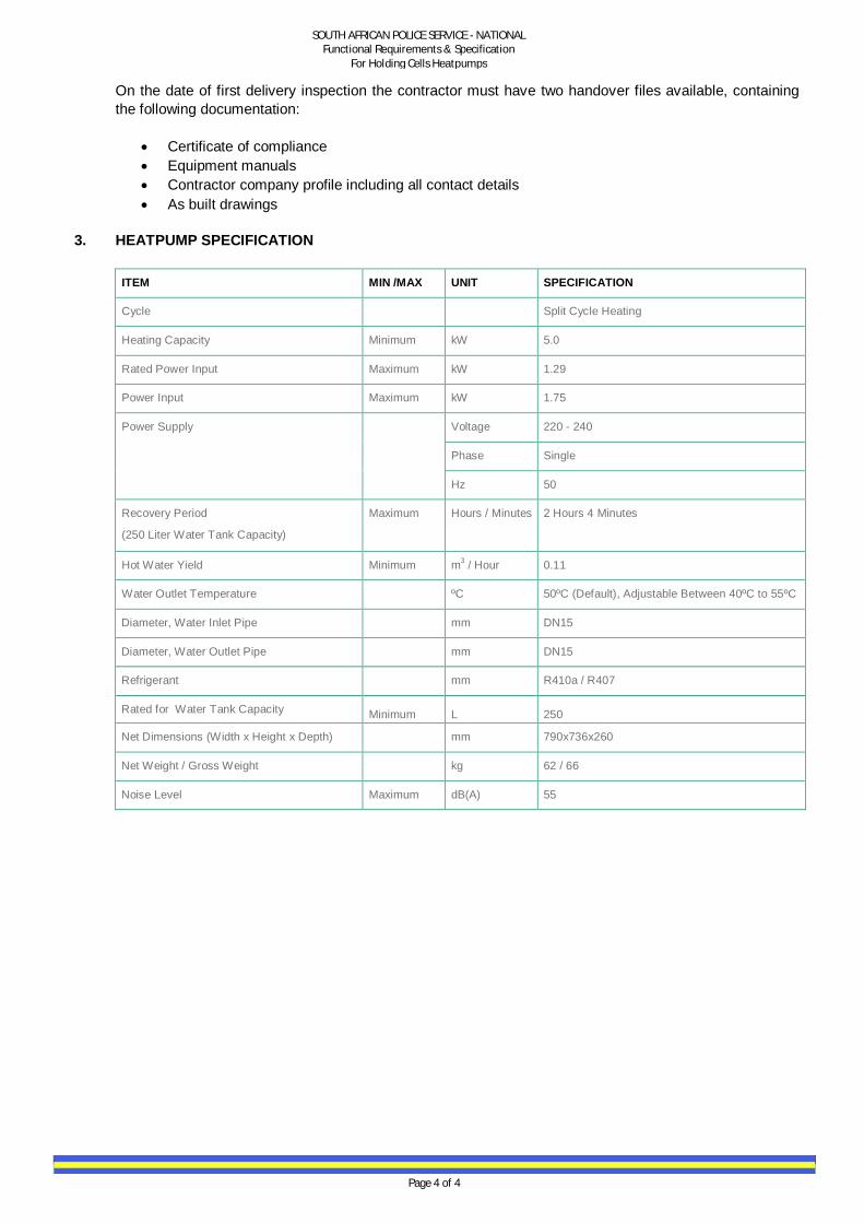
3. HEATPUMP SPECIFICATION
ITEM MIN /MAX UNIT SPECIFICATION
Cycle Split Cycle Heating
Heating Capacity Minimum kW 5.0
Rated Power Input Maximum kW 1.29
Power Input Maximum kW 1.75
Power Supply Voltage 220 - 240
Phase Single
Hz 50
Recovery Period
(250 Liter Water Tank Capacity)
Maximum Hours / Minutes 2 Hours 4 Minutes
Hot Water Yield Minimum m3 / Hour 0.11
Water Outlet Temperature ºC 50ºC (Default), Adjustable Between 40ºC to 55ºC
Diameter, Water Inlet Pipe mm DN15
Diameter, Water Outlet Pipe mm DN15
Refrigerant mm R410a / R407
Rated for Water Tank Capacity Minimum L 250
Net Dimensions (Width x Height x Depth) mm 790x736x260
Net Weight / Gross Weight kg 62 / 66
Noise Level Maximum dB(A) 55

SAPS EXPERT SERVICES
TECHNICAL SPECIFICATION FOR LUMINAIRES FOR CELL BLOCK AND POLICE ID PARADE
ROOMS ONLY
ADDENDUM D
VERSION:- 1.1 UPDATED:- DEC 2011

TECHNICAL SPECIFICATION MM01-11:- ROUGHGUARD POLICE HOLDING CELL LUMINAIRE.
1 | P a g e
ADDENDUM D VANDAL-PROOF FLUORESCENT LUMINAIRE FOR USE IN HOSTILE AND VANDAL-PRONE ENVIRONMENTS. The luminaire shall consist of a rigid high pressure die cast marine grade aluminium body with a robust, one-piece injection moulded clear polycarbonate,vandal proof diffuser. The diffuser shall have a smooth outer surface and be designed to proved sufficient upward light distribution to illuminate the ceiling, thus providing adequate light for seaching of the holding cell. The luminaire shall be designed to operate 14/28/35/54W T5 linear fluorescent lamps. As an option the luminaire can be supplied with 3*1 Watt LED's to serve as a nightlight. The luminaire shall bear the SANS 60598-2-1 safety mark. The luminaire shall have a degree of protection that complies with SANS 60598-1: Lamp compartment: IP65. The IP rating shall be certified by a SANS Test Report. The luminaire shall have no dust collecting edges and it shall not be possible to manually grip the luminaire once mounted. A minimum of mounting studs shall be provided for mounting the luminaire. A cable entry of 20mm shall be provided in centre of the body. There shall be no sharp edges or corners along any accessable surfaces of the luminaire. The vandal-proof diffuser shall be secured the the aluminium body by means of 6 (six) tamper-proof (TPS/MJM/M6) Stainless Steel Allen Cap Screws. A silicone sponge gasket shall ensure reliable IP65 rating, as certified. The removable gear tray shall be manufactured from 0.7mm mild steel, powder coated white to optimise luminaire efficiency. All paint finishes shall be done in accordance with the SANS 1274 Standard. All holes and cut-outs on the gear tray shall be done prior to powder coating. All control gear components shall be mounted on the gear tray. The gear tray can be removed by loosening four Allen Cap screws in keyhole slots, which allow the gear tray to be relieved into a suspended position, ensuring ease of maintenance. All electronic control gear components shall be removable and bear the relevant SABS mark. All screws, bolts and metal parts shall be stainless steel or non-corrosive material. Mains connections shall be by means of a suitable screw terminal block with a wire clamping contact. All internal wiring to the lampholders or LED's shall be hidden behind the gear tray and not be visible through the diffuser. The luminaire shall be power factor corrected to a minimum of 0,9. The luminaire must be able to withstand an ambient temprature of at least 45 deg C, without resulting in any electrical or mechanical components exceeding it's maximum allowed operating tempreture. Certified proof from an authorizes testing facility shall be available on request.

TECHNICAL SPECIFICATION MM01-11:- ROUGHGUARD POLICE HOLDING CELL LUMINAIRE.
2 | P a g e
Picture for Illustration Purposes ONLY
TECHNICAL SPECIFICATION MM05-11:- DECORATIVE RND LED BULKHEAD FOR GENERAL LIGHTING AROUND POLICE STATIONS. ADDENDUM D
1 | P a g e
DESIGNED FOR DECORATIVE AND EFFICIENT BULKHEAD LIGHTING IN VANDAL-PRONE INDOOR OR OUTDOOR APPLICATIONS.
The luminaire shall consist of a high pressure die cast aluminium base and trim ring, and an opal high impact acrylic diffuser. It shall be designed to operate 6* High Power LEDs driven at 700mA.
The luminaire shall bear the SANS 60598-1 safety mark. The luminaire shall have a degree of protection that complies with SANS 60598-2-1: Lamp compartment: IP65
The IP rating shall be certified by a SABS test report.
All base castings shall be manufactured from high pressure die cast aluminium, finished both outside and inside in white epoxy powder coating for added protection and reflectivity. It shall be simple to install due to four mounting holes provided outside the lamp compartment through lugs that form part of the base casting. The trim ring casting shall be mounted onto the base casting by 4 stainless steel M5 Allen head screws, located outside the lamp compartment. These screws can be supplied in the Tamper-proof type (TPS/MM/M5) as well as the fixing holes can be supplied with stainless steel helicoil inserts on request. An opal non-discolouring high impact acrylic injection moulded diffuser shall be used throughout the range. It shall offer excellent vandal resistance, be highly translucent and shall not discolour even when subjected to the harshest UV environments. A silicon sponge gasket shall be fitted into a special groove in the diffuser to prevent damage to the gasket during installation and to achieve the certified ingress protection rating of IP65. The lamp compartment shall be permanently sealed to the base casting The trim ring casting shall be manufactured from high pressure die cast aluminium and shall be finished in a special multi-stage epoxy powder surface coating. The control gear shall be mounted directly onto the base casting, ensuring cool operation. It shall be suitable for operation with the specified rating of the lamp on a 230V +3%/-10% 50Hz single phase system. All inter-connecting wiring shall be Teflon® insulated with protective sleeving to prevent damage by possible abrasion. All external screws, bolts and metals shall be stainless steel or non-corrosive material. Mains connections shall be by means of a suitable screw terminal block with a wire clamping contact. The luminaire shall be power factor corrected to a minimum of 0.9. In the LED version, the diffuser shall be permanently sealed by means of silicon to the aluminium base and shall be supplied with a 300mm supply lead. The LED's and control gear are designed to ensure a maintenance-free operation of no less than 50 000 hrs.The control gear shall incorporate an automatic reversible over temperature protection. The unit shall be EMC compliant to the EN55015 and EN61347-1 standard. And conform to IEC 61347-2-13, IEC 62384, IEC 61000-3-2, IEC 61000-3-3, and IEC 61547.

TECHNICAL SPECIFICATION MM05-11:- DECORATIVE RND LED BULKHEAD FOR GENERAL LIGHTING AROUND POLICE STATIONS. ADDENDUM D
2 | P a g e
In terms of a LED version, the LEDs have to provide a light of a neutral colour temperature (4,500K). A report from the LED vendor, for LED’s used in the luminaire, shall be submitted, which shall include the following documentary evidence: • Measured LED junction temperature for a given test condition and extrapolated for
an ambient temperature of 35°C. • LED drive current. • LED manufacturer data that clearly correlates LED junction temperature and LED
drive current to lumen maintenance. • The LED datasheets, indicating the Byy, Lxx data, as provided by the LED
manufacturer.
PICTURES FOR ILLUSTRATION PURPOSES ONLY
TECHNICAL SPECIFICATION MM07-11:- VANDAL RESISTANT RND LED BULKHEAD FOR EXERCISE YARDS IN CELL BLOCKS. ADDENDUM D
1 | P a g e
DESIGNED FOR DECORATIVE AND EFFICIENT BULKHEAD LIGHTING IN VANDAL-PRONE INDOOR OR OUTDOOR APPLICATIONS.
The luminaire shall consist of a high pressure die cast aluminium base and trim ring, and an opal high impact acrylic diffuser. It shall be designed to operate 6* High Power LEDs driven at 700mA.
The luminaire shall bear the SANS 60598-1 safety mark. The luminaire shall have a degree of protection that complies with SANS 60598-2-1: Lamp compartment: IP65
The IP rating shall be certified by a SABS test report.
All base castings shall be manufactured from high pressure die cast aluminium, finished both outside and inside in white epoxy powder coating for added protection and reflectivity. It shall be simple to install due to four mounting holes provided outside the lamp compartment through lugs that form part of the base casting. The trim ring casting shall be mounted onto the base casting by 4 stainless steel M5 Allen head screws, located outside the lamp compartment. These screws can be supplied in the Tamper-proof type (TPS/MM/M5) as well as the fixing holes can be supplied with stainless steel helicoil inserts on request. An opal non-discolouring high impact acrylic injection moulded diffuser shall be used throughout the range. It shall offer excellent vandal resistance, be highly translucent and shall not discolour even when subjected to the harshest UV environments. A silicon sponge gasket shall be fitted into a special groove in the diffuser to prevent damage to the gasket during installation and to achieve the certified ingress protection rating of IP65. The lamp compartment shall be permanently sealed to the base casting The trim ring casting shall be manufactured from high pressure die cast aluminium and shall be finished in a special multi-stage epoxy powder surface coating. The control gear shall be mounted directly onto the base casting, ensuring cool operation. It shall be suitable for operation with the specified rating of the lamp on a 230V +3%/-10% 50Hz single phase system. All inter-connecting wiring shall be Teflon® insulated with protective sleeving to prevent damage by possible abrasion. All external screws, bolts and metals shall be stainless steel or non-corrosive material. Mains connections shall be by means of a suitable screw terminal block with a wire clamping contact. The luminaire shall be power factor corrected to a minimum of 0.9. In the LED version, the diffuser shall be permanently sealed by means of silicon to the aluminium base and shall be supplied with a 300mm supply lead. The LED's and control gear are designed to ensure a maintenance-free operation of no less than 50 000 hrs.The control gear shall incorporate an automatic reversible over temperature protection. The unit shall be EMC compliant to the EN55015 and EN61347-1 standard. And conform to IEC 61347-2-13, IEC 62384, IEC 61000-3-2, IEC 61000-3-3, and IEC 61547.

TECHNICAL SPECIFICATION MM07-11:- VANDAL RESISTANT RND LED BULKHEAD FOR EXERCISE YARDS IN CELL BLOCKS. ADDENDUM D
2 | P a g e
In terms of a LED version, the LEDs have to provide a light of a neutral colour temperature (4,500K). A report from the LED vendor, for LED’s used in the luminaire, shall be submitted, which shall include the following documentary evidence: • Measured LED junction temperature for a given test condition and extrapolated for
an ambient temperature of 35°C. • LED drive current. • LED manufacturer data that clearly correlates LED junction temperature and LED
drive current to lumen maintenance. • The LED datasheets, indicating the Byy, Lxx data, as provided by the LED
manufacturer.
PICTURES FOR ILLUSTRATION PURPOSES ONLY

TECHNICAL SPECIFICATION MM09.1-11:- LED WALL WASHER LUMINAIRE LED BEAM 1200 FOR POLICE ID PARADE ROOMS(OPTION 1) ADDENDUM D
1 | P a g e
DESIGNED FOR DECORATIVE IDENTIFICATION AND FAÇADE LIGHTING APPLICATIONS IN INDOOR AND OUTDOOR ENVIRONMENTS The luminaire shall consist of an aluminium extrusion body and die-cast aluminium end-caps creating the best thermal environment for LEDs. Cable entry shall be available in different positions. SANS 60598-2-5 safety mark. IP66 in compliance with SANS 60598-2-5. The IP-rating is certified by an SABS test report. The LED Package Shall be 48w 24*2 – 3840 lumen Luminaire body shall be 1200mm in length. The luminaire housing shall be robustly constructed, weather proof, hail proof, corrosion proof and vandal resistant. It shall be manufactured from corrosion-resistant aluminium. A silicon gasket, between the flush-mounted PMMA front cover and housing, shall ensure the sealing of the luminaire. The gasket sealing shall be made to match the extended lifetime of the LEDs (50 000 hours). The LED’s shall have a minimum 50 000hrs lifetime. Effective high-power OSRAM LED, 4500K at a colour rendering index >85. The incorporated lens system shall be available in Narrow Beam, Middle Beam, Wide Beam and Elliptical Beam. The LED drivers shall be incorporated in the luminaire housing and powered with 24V DC. An optional external power supply for operation on a 230V ±10% 50 Hz single-phase system shall be located in an external compartment due to thermal and maintenance reasons. Optional DMX or DALI dimming (0%-100%) can be incorporated into the external control gear compartment. The luminaire shall be linearly dimmable to achieve the required 1:7 dimming ratio. The luminaire shall be supplied with an adjustable mounting bracket to ensure that the correct distribution angle can be achieved on site.
PICTURES ARE FOR ILLUSTRATION PURPOSES ONLY
TECHNICAL SPECIFICATION MM09.2-11:-ADJUSTABLE DSR FLOURESCENT WALL WASHER LUMINAIRE FOR POLICE ID PARADE ROOMS (OPTION 2)
1 | P a g e
ADDENDUM D DESIGNED FOR FLUORESCENT LIGHTING IN ID PARADE ROOMS WHERE ADJUSTABE LINEAR LIGHTING IS REQUIRED. The luminaire shall consist of an injection-moulded, flame-retardant GRP body and lid with clip in lamp holders for both single and double lamp versions. It shall be designed to operate fluorescent lamps up to 1*58W. The luminaire shall bear the SANS 60598-2-1 safety mark. The luminaire shall have a degree of protection that complies with SANS 60598-2-1: Lamp compartment: IP65 Body: IP65 The body shall be manufactured from injection-moulded, flame-retardant glass fibre reinforced polyester and shall be provided with a knockout facility at each end, making it suitable for surface wiring. Four plastic bolts shall be clipped into the body onto which the lid screws tight. A silicon sponge gasket shall be fitted into a groove arrangement on the body. For mounting, two holes shall be provided in the base of the body. The lid shall be manufactured from the same material as the body and shall be designed in such a way that it can accommodate the applicable control gear for the various lamp wattages. The lid shall be screwed down onto the body by four GRP wingnut shaped fasteners that screw into the stainless steel bolts provided in the body. External access to the starter shall be achieved by removing a screw cap cover. Two rectangular shaped holes shall be provided on the lid to accommodate the clip-in lamp holders, which shall be provided with gaskets to ensure the integrity of the IP rating. The DIMMABLE ELECTRONIC ballast shall be mounted directly onto bosses provided on the lid,The Dimmable ECG shall ensure that the required 7:1 ration between both rooms can be achieved. All control gear components shall be removable and shall bear the relevant SABS mark. Mains connections shall be by means of a suitable screw terminal block with a wire clamping contact. The luminaire shall be power factor corrected to a minimum of 0,9 The luminaire shall be equipped with an adjustable enclosed DSR reflector system. This reflector shall be manufactured of polycarbonate and be vacuum metalised in the inside to proved even, clear illumination.
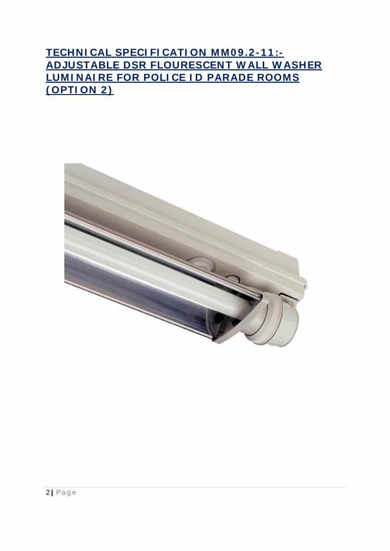
TECHNICAL SPECIFICATION MM09.2-11:-ADJUSTABLE DSR FLOURESCENT WALL WASHER LUMINAIRE FOR POLICE ID PARADE ROOMS (OPTION 2)
2 | P a g e

TECHNICAL SPECIFICATION MM10-11:- DECORATIVE RND LED BULKHEAD LUMINAIRE FOR STAFF AND PUBLIC TOILETS IN POLICE STATIONS. ADDENDUM D
1 | P a g e
DESIGNED FOR DECORATIVE AND EFFICIENT BULKHEAD LIGHTING IN VANDAL-PRONE INDOOR OR OUTDOOR APPLICATIONS.
The luminaire shall consist of a high pressure die cast aluminium base and trim ring, and an opal high impact acrylic diffuser. It shall be designed to operate 6* High Power LEDs driven at 700mA.
The luminaire shall bear the SANS 60598-1 safety mark. The luminaire shall have a degree of protection that complies with SANS 60598-2-1: Lamp compartment: IP65
The IP rating shall be certified by a SABS test report.
All base castings shall be manufactured from high pressure die cast aluminium, finished both outside and inside in white epoxy powder coating for added protection and reflectivity. It shall be simple to install due to four mounting holes provided outside the lamp compartment through lugs that form part of the base casting. The trim ring casting shall be mounted onto the base casting by 4 stainless steel M5 Allen head screws, located outside the lamp compartment. These screws can be supplied in the Tamper-proof type (TPS/MM/M5) as well as the fixing holes can be supplied with stainless steel helicoil inserts on request. An opal non-discolouring high impact acrylic injection moulded diffuser shall be used throughout the range. It shall offer excellent vandal resistance, be highly translucent and shall not discolour even when subjected to the harshest UV environments. A silicon sponge gasket shall be fitted into a special groove in the diffuser to prevent damage to the gasket during installation and to achieve the certified ingress protection rating of IP65. The lamp compartment shall be permanently sealed to the base casting The trim ring casting shall be manufactured from high pressure die cast aluminium and shall be finished in a special multi-stage epoxy powder surface coating. The control gear shall be mounted directly onto the base casting, ensuring cool operation. It shall be suitable for operation with the specified rating of the lamp on a 230V +3%/-10% 50Hz single phase system. All inter-connecting wiring shall be Teflon® insulated with protective sleeving to prevent damage by possible abrasion. All external screws, bolts and metals shall be stainless steel or non-corrosive material. Mains connections shall be by means of a suitable screw terminal block with a wire clamping contact. The luminaire shall be power factor corrected to a minimum of 0.9. In the LED version, the diffuser shall be permanently sealed by means of silicon to the aluminium base and shall be supplied with a 300mm supply lead. The LED's and control gear are designed to ensure a maintenance-free operation of no less than 50 000 hrs.The control gear shall incorporate an automatic reversible over temperature protection. The unit shall be EMC compliant to the EN55015 and EN61347-1 standard. And conform to IEC 61347-2-13, IEC 62384, IEC 61000-3-2, IEC 61000-3-3, and IEC 61547.

TECHNICAL SPECIFICATION MM10-11:- DECORATIVE RND LED BULKHEAD LUMINAIRE FOR STAFF AND PUBLIC TOILETS IN POLICE STATIONS. ADDENDUM D
2 | P a g e
In terms of a LED version, the LEDs have to provide a light of a neutral colour temperature (4,500K). A report from the LED vendor, for LED’s used in the luminaire, shall be submitted, which shall include the following documentary evidence: • Measured LED junction temperature for a given test condition and extrapolated for
an ambient temperature of 35°C. • LED drive current. • LED manufacturer data that clearly correlates LED junction temperature and LED
drive current to lumen maintenance. • The LED datasheets, indicating the Byy, Lxx data, as provided by the LED
manufacturer.
PICTURES FOR ILLUSTRATION PURPOSES ONLY

TECHNICAL SPECIFICATION MM11-11:- CIRCULAR RECESSED CFL DOWNLIGHTER FOR OFFICES AND PASSAGES IN POLICE STATIONS.(OPTION1) ADDENDUM D
1 | P a g e
DESIGNED FOR DECORATIVE LIGHTING APPLICATIONS IN MODERN OR HI-TECH ENVIRONMENTS The luminaire shall consist of a pressed metal ceiling trim, reflector, ceiling brackets and reinforced luminaire frame supporting the lamp holder and enclosed control gear. It shall be designed to operate incandescent lamps up to 100W and compact fluorescent lamps in the Dulux S range and Dulux D range up to 2x26W. The easy-fixing ceiling brackets shall be made of spring steel to ensure rigid and positive mounting in the ceiling, eliminating any sagging of the luminaire. The ceiling trim shall be manufactured from pressed metal for rigidity which shall be iron phosphated against rust before finally being coated with a pigmented UV blocking hybrid polyester powder and thereafter oven baked at 210°C. The luminaire shall bear the SANS 60598-2-1 safety mark. HORIZONTAL LAMP POSITION The RONDO-H shall be designed for lamps used in the horizontal position. The 99.9% pure aluminium reflector shall be made from pressed grade 1050 aluminium alloy. The surface finish of the reflector shall be achieved by a vacuumed metalised coating with a thickness of 30-40 microns. The reflector shall be finished in a diamond faceted and orange peel appearance to give a superior photometric distribution with high spacing to mounting height ratios and low glare ratings. VERTICAL LAMP POSITION The RONDO-V shall be designed for lamps used in the vertical position. The 99.9% pure aluminium reflector shall be made from pressed grade 1050 aluminium alloy. The surface finish of the reflector shall be achieved by a vacuumed metalised coating with a thickness of 30-40 microns. The reflector shall be finished in a striped and dot pattern with a sand blast appearance to give a superior photometric distribution with high spacing to mounting height ratios and low glare ratings. The lamp holder shall comply with VC 8011 as well as VDE and IEC standards. The control gear shall be integral. The luminaire shall be available in either an electro-magnetic ballast or electronic control gear. It shall be suitable for operation with the specified rating of the lamp on a 230V +3%/-10% 50Hz single phase system. All internal wiring shall be Teflon® coated with protective sleeving to prevent damage by possible abrasion. All screws, bolts, nuts and metal parts shall be stainless steel or of non-corrosive material. Mains connections shall be by means of a suitable screw terminal block. The downlight shall be supplied with 6Amp plug-top on 3m cabtyre. The luminaire shall be power factor corrected to a minimum of 0,9.

TECHNICAL SPECIFICATION MM11-11:- CIRCULAR RECESSED CFL DOWNLIGHTER FOR OFFICES AND PASSAGES IN POLICE STATIONS.(OPTION1) ADDENDUM D
2 | P a g e
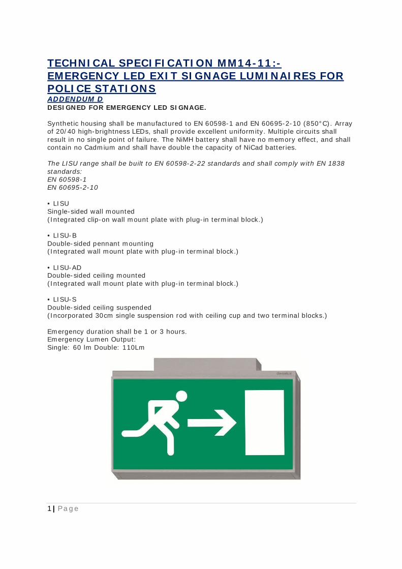
TECHNICAL SPECIFICATION MM14-11:- EMERGENCY LED EXIT SIGNAGE LUMINAIRES FOR POLICE STATIONS ADDENDUM D
1 | P a g e
DESIGNED FOR EMERGENCY LED SIGNAGE. Synthetic housing shall be manufactured to EN 60598-1 and EN 60695-2-10 (850°C). Array of 20/40 high-brightness LEDs, shall provide excellent uniformity. Multiple circuits shall result in no single point of failure. The NiMH battery shall have no memory effect, and shall contain no Cadmium and shall have double the capacity of NiCad batteries. The LISU range shall be built to EN 60598-2-22 standards and shall comply with EN 1838 standards: EN 60598-1 EN 60695-2-10 • LISU Single-sided wall mounted (Integrated clip-on wall mount plate with plug-in terminal block.) • LISU-B Double-sided pennant mounting (Integrated wall mount plate with plug-in terminal block.) • LISU-AD Double-sided ceiling mounted (Integrated wall mount plate with plug-in terminal block.) • LISU-S Double-sided ceiling suspended (Incorporated 30cm single suspension rod with ceiling cup and two terminal blocks.) Emergency duration shall be 1 or 3 hours. Emergency Lumen Output: Single: 60 lm Double: 110Lm
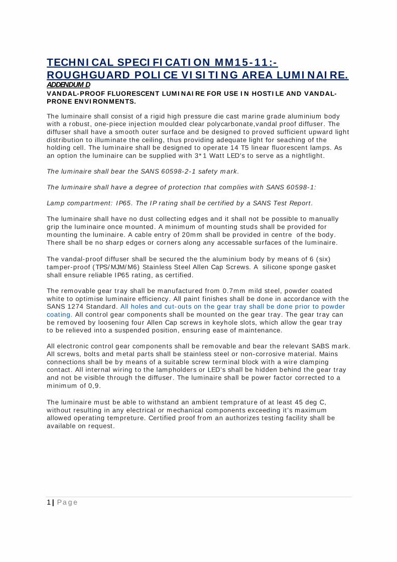
TECHNICAL SPECIFICATION MM15-11:- ROUGHGUARD POLICE VISITING AREA LUMINAIRE.
1 | P a g e
ADDENDUM D VANDAL-PROOF FLUORESCENT LUMINAIRE FOR USE IN HOSTILE AND VANDAL-PRONE ENVIRONMENTS. The luminaire shall consist of a rigid high pressure die cast marine grade aluminium body with a robust, one-piece injection moulded clear polycarbonate,vandal proof diffuser. The diffuser shall have a smooth outer surface and be designed to proved sufficient upward light distribution to illuminate the ceiling, thus providing adequate light for seaching of the holding cell. The luminaire shall be designed to operate 14 T5 linear fluorescent lamps. As an option the luminaire can be supplied with 3*1 Watt LED's to serve as a nightlight. The luminaire shall bear the SANS 60598-2-1 safety mark. The luminaire shall have a degree of protection that complies with SANS 60598-1: Lamp compartment: IP65. The IP rating shall be certified by a SANS Test Report. The luminaire shall have no dust collecting edges and it shall not be possible to manually grip the luminaire once mounted. A minimum of mounting studs shall be provided for mounting the luminaire. A cable entry of 20mm shall be provided in centre of the body. There shall be no sharp edges or corners along any accessable surfaces of the luminaire. The vandal-proof diffuser shall be secured the the aluminium body by means of 6 (six) tamper-proof (TPS/MJM/M6) Stainless Steel Allen Cap Screws. A silicone sponge gasket shall ensure reliable IP65 rating, as certified. The removable gear tray shall be manufactured from 0.7mm mild steel, powder coated white to optimise luminaire efficiency. All paint finishes shall be done in accordance with the SANS 1274 Standard. All holes and cut-outs on the gear tray shall be done prior to powder coating. All control gear components shall be mounted on the gear tray. The gear tray can be removed by loosening four Allen Cap screws in keyhole slots, which allow the gear tray to be relieved into a suspended position, ensuring ease of maintenance. All electronic control gear components shall be removable and bear the relevant SABS mark. All screws, bolts and metal parts shall be stainless steel or non-corrosive material. Mains connections shall be by means of a suitable screw terminal block with a wire clamping contact. All internal wiring to the lampholders or LED's shall be hidden behind the gear tray and not be visible through the diffuser. The luminaire shall be power factor corrected to a minimum of 0,9. The luminaire must be able to withstand an ambient temprature of at least 45 deg C, without resulting in any electrical or mechanical components exceeding it's maximum allowed operating tempreture. Certified proof from an authorizes testing facility shall be available on request.

TECHNICAL SPECIFICATION MM15-11:- ROUGHGUARD POLICE VISITING AREA LUMINAIRE.
2 | P a g e
Picture for Illustration Purposes ONLY

TECHNICAL SPECIFICATION MM16-11:- VANDAL-RESISTANT LED BULKHEAD FOR POLICE SERVICE DUCTS AND STORE ROOMS. ADDENDUM D
1 | P a g e
DESIGNED FOR INDUSTRIAL AND PUBLIC LIGHTING APPLICATIONS WHERE EFFICIENCY, VANDAL RESISTANCE AND MECHANICAL RELIABILITY ARE ESSENTIAL.
The luminaire shall consist of a high pressure die cast aluminium body and a structured clear high impact acrylic diffuser. It shall be rectangular in shape and shall be designed to operate 6* HIGH POWERED LED'S.The luminaire shall be equipped a hot dipped galvanized wire guard. The luminaire shall bear the SANS 60598--2-1 safety mark. The luminaire shall have a degree of protection that complies with SANS 60598-2-1: Lamp compartment: IP65 The IP rating shall be certified by a SABS test report. The body shall be manufactured from high pressure die cast aluminium, powder coated in the colour specified for added protection. It shall be suitable for surface mounting and shall allow for surface conduits to enter. A silicone sponge gasket shall be fitted into a groove in the body. Mounting holes, complete with nylon washers, can be provided on request. The LED version shall be supplied with the /ML accessory. The diffuser shall be manufactured from injection-moulded, high-impact, non-discolouring acrylic. It shall be structured on the inside and smooth on the outside. The diffuser shall be held to the body by four captive stainless steel Allen head screws. A tongue arrangement provided on the diffuser shall ensure the integrity of the IP rating. The geartray shall be manufactured from 1.6mm galvanised and passivated steel, powder coated white to prevent corrosion and improve reflectance. All electrical components and lamp holders shall be mounted on the geartray. It shall be suitable for operation with the specified rating of the lamp on a 230V +3%/-10% 50Hz single phase system. All control gear components shall be removable and bear the relevant SABS mark. All internal wiring shall be Teflon® coated with protective sleeving to prevent damage by possible abrasion. All screws, bolts and metal parts shall be stainless steel or non corrosive material. Mains connections shall be by means of a suitable screw terminal block with a wire clamping contact. The luminaire shall be power factor corrected to a minimum of 0,9. In the LED version, the diffuser shall be permanently sealed to the aluminium base and shall be supplied with a 0.5m long 1mm2 silicone cabtyre. The control gear shall incorporate an automatic reversible over temperature protection. The LED's and control gear shall be designed to ensure a maintenance-free operation of no less than 50000 hrs. The unit shall be EMC compliant to the EN 55015 and EN 61347-1 Standard. It Shall also conform to IEC613-2-13, IEC62384, IEC61000-3-2, IEC61000-3-3 and IEC61547. The LED's in the luminaire shall provide a light of a (4500K) Neutral colour temp.
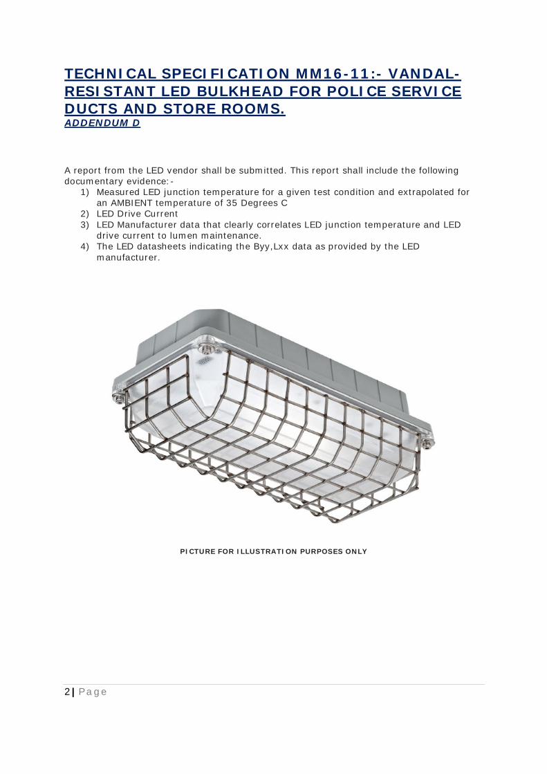
TECHNICAL SPECIFICATION MM16-11:- VANDAL-RESISTANT LED BULKHEAD FOR POLICE SERVICE DUCTS AND STORE ROOMS. ADDENDUM D
2 | P a g e
A report from the LED vendor shall be submitted. This report shall include the following documentary evidence:-
1) Measured LED junction temperature for a given test condition and extrapolated for an AMBIENT temperature of 35 Degrees C
2) LED Drive Current 3) LED Manufacturer data that clearly correlates LED junction temperature and LED
drive current to lumen maintenance. 4) The LED datasheets indicating the Byy,Lxx data as provided by the LED
manufacturer.
PICTURE FOR ILLUSTRATION PURPOSES ONLY