project 3.1 retrofit fluorescent dimming with integrated ... · pdf filecalifornia energy...
TRANSCRIPT

CALIFORNIA ENERGY
COMMISSION
PIER Lighting Research ProgramProject 3.1 Retrofit Fluorescent Dimming with
Integrated Lighting Controls
FINAL REPORT
Con
sulta
nt R
epor
t
November 2004 500-01-041-A-5
Arnold Schwarzenegger, Governor

Deliverable 3.1.10 Final Report LBNL/Architectural Energy Corporation
PIER Lighting Research Program 2 500-01-041
CALIFORNIA
ENERGY
COMMISSION
Prepared By: Lawrence Berkeley National Laboratory Frances Rubinstein, Project Lead Berkeley, CA Managed By: Architectural Energy Corporation Judie Porter Program Director Boulder, CO CEC Contract # 500-01-041 Prepared For: Don Aumann Contract Manager Nancy Jenkins PIER Buildings Program Manager DISCLAIMER This report was prepared as the result of work sponsored by the
California Energy Commission. It does not necessarily represent the views of the Energy Commission, its employees or the State of California. The Energy Commission, the State of California, its employees, contractors and subcontractors make no warrant, express or implied, and assume no legal liability for the information in this report; nor does any party represent that the uses of this information will not infringe upon privately owned rights. This report has not been approved or disapproved by the California Energy Commission nor has the California Energy Commission passed upon the accuracy or adequacy of the information in this report.

Deliverable 3.1.10 Final Report LBNL/Architectural Energy Corporation
PIER Lighting Research Program 3 500-01-041
Contact Information: Subcontract Project Manager Francis Rubinstein Lawrence Berkeley National Laboratory 1 Cyclotron Rd., Building 90R3111 Berkeley, CA 94720 510 486-4096 – Voice 510 486-4089 – Fax [email protected]
AEC Program Director Judie Porter Architectural Energy Corporation 2540 Frontier Avenue Boulder, CO 80301 303-444-4149 – Voice 303-444-4304 - Fax [email protected]
Prepared By: Francis Rubinstein, Lawrence Berkeley National Laboratory Pete Pettler, Vistron Joel Snook, Vistron Project Team: Francis Rubinstein, Lawrence Berkeley National Laboratory Pete Pettler, Vistron Joel Snook, Vistron Erik Engelking, Vistron Jim Galvin, Lawrence Berkeley National Laboratory Dennis DiBartolomeo, Lawrence Berkeley National Laboratory Sila Kiliccote, Lawrence Berkeley National Laboratory
This work was completed under contract to Lawrence Berkeley National Laboratory as part of the California Energy Commission’s Lighting Research Program. This program is supported by the California Energy Commission’s Public Interest Energy Research (PIER) Buildings Program and the Assistant Secretary for Energy Efficiency and Renewable Energy, Office of Building Technology, Building Technologies Program, of the U.S. Department of Energy under Contract No. DE-AC03-76SF00098.

Deliverable 3.1.10 Final Report LBNL/Architectural Energy Corporation
PIER Lighting Research Program 4 500-01-041
Acknowledgements The Team wishes to acknowledge George Loisos for his leadership of the Demand Responsive Element and his organization of the project and the Technical Advisory Group meetings. The Team also wishes to thank the members of Technical Advisory Group, especially AJ Glaser (Hunt Dimming Controls) and Stuart Berjansky (Advance Transformer) for contributing their expertise and technical wisdom. The Team wishes to acknowledge the invaluable assistance of PG&E in the testing of the original Integrated Lighting Control system, especially Steve Blanc and Dixon Kerr, who arranged for the technical testing to be performed at PG&E’s Thermal Testing Facility in San Ramon, and Dan Kaufman and who actually performed the tests. The Team wishes to acknowledge the contribution of the below individuals: Program Advisory Committee: Ron Lewis, Department of Energy; Jerry Mills, Easy Lite; Gregg Ander, SCE; Bill Daiber, WFD Associates; James Bryan, Arden Realty; Neall Digert, Solatube; Jim Benya, Benya Lighting; Dennis Tiede, Sempra Utilities; Noah Horowitz, NRDC; Amy Cortese, Northwest Energy Efficiency Alliance; Pekka Hakkarainen, Lutron; Peter Turnbull, PG&E; Michael Waxer, Carmel Development Co; Kit Tuveson, Tuveson & Associates; David Kaneda, Integrated Design Associates, Inc; Connie Buchan, SMUD. Program and Contract Management: Eric Stubee and Nancy Jenkins, California Energy Commission; Karl Johnson, CIEE; Judie Porter, Architectural Energy Corporation; Don Aumann, CLTC.

Deliverable 3.1.10 Final Report LBNL/Architectural Energy Corporation
PIER Lighting Research Program 5 500-01-041
Table of Contents Acknowledgements ......................................................................................................................... 4 Preface ............................................................................................................................................. 8 Executive Summary ........................................................................................................................ 9
Project Objectives ....................................................................................................................... 9 Project Outcomes ...................................................................................................................... 10 Conclusions............................................................................................................................... 11 Recommendations..................................................................................................................... 11 Benefits to California ................................................................................................................ 12
Abstract ......................................................................................................................................... 14 Introduction ................................................................................................................................... 15
Background and Overview........................................................................................................ 15 Project Objectives ..................................................................................................................... 16 Report Organization.................................................................................................................. 16
Project Approach........................................................................................................................... 18 Project Tasks ............................................................................................................................. 18 Changes and Modifications....................................................................................................... 18
Project Outcomes .......................................................................................................................... 19 Summary of Project Outcomes ................................................................................................. 19 System Overview ...................................................................................................................... 19 Development of the Intelligent Junction Box and PCC System (Task 3.1.1) ........................... 21 Environmental Sensor (Task 3.1.2)........................................................................................... 25 Interfacing the Multi-Sensor to PC (Task 3.1.3)....................................................................... 28 Bluetooth Communications Link (Task 3.1.4 and 3.1.5) .......................................................... 29 Control Software (Task 3.1.6).................................................................................................. 30 Data collection .......................................................................................................................... 30 Bluetooth communications ....................................................................................................... 32 User Interface............................................................................................................................ 33 Desktop Demonstration System................................................................................................ 35 Elapsed Energy Consumption ................................................................................................... 38 Workstation Occupancy Sensor ................................................................................................ 39 Date and Time Stamp................................................................................................................ 39 Benefits of Proposed System (Task 3.1.7) ................................................................................ 41 Codes and Standards ................................................................................................................. 45
Conclusions and Recommendations.............................................................................................. 47 Recommendations..................................................................................................................... 47 Commercialization Potential ..................................................................................................... 47 Benefits to California ................................................................................................................ 48 Conclusions............................................................................................................................... 49
Appendix A. Guide to operation of the Phase Cut Carrier System .............................................. 50 Appendix B. Firmware Documentation for Phase Cut Carrier Encoder ...................................... 59 Appendix C. Instructions for Making an Environmental Sensor ................................................. 69

Deliverable 3.1.10 Final Report LBNL/Architectural Energy Corporation
PIER Lighting Research Program 6 500-01-041
List of Figures Figure 1. Diagram of the Phase-Cut Carrier System. ................................................................... 20 Figure 2. Total harmonic current for four different ballasts operating two T-8 lamps under full
light output and dimmed to five percent light output. Data from Advance Transformer Atlas 2002-2003. ............................................................................................................................ 22
Figure 3. Proposed Retrofit Fluorescent Dimming System.......................................................... 23 Figure 4. Comparison of (a) current THD and (b) power values for different operating conditions.
.............................................................................................................................................. 24 Figure 5. Screen captures showing current THD for the encoder at (a) 100% and (b) 25%. ....... 24 Figure 6. Graphic representation of pushbutton operation. .......................................................... 25 Figure 7. Percent error for measuring daylight with photocell calibrated with SP35 fluorescent
lamp. ..................................................................................................................................... 27 Figure 8. Prototype of the environmental sensor.......................................................................... 28 Figure 9. Screen capture of PCC control panel, shown in expanded mode.................................. 33 Figure 10. Entire desktop demonstration of the Phase Cut Carrier system. ................................. 35 Figure 11. Closer view of the entire desktop demonstration of the Phase Cut Carrier system. ... 35 Figure 12. View of the lights at the top of the desktop demonstration of the Phase Cut Carrier
system. .................................................................................................................................. 36 Figure 13. Closeup of the PCC Decoder and the electronic dimming ballast (0-10 VDC)
controlled by the system. ...................................................................................................... 36 Figure 14. Closeup shot of the PCC Decoder showing the electrical connections between the
decoder and the ballast.......................................................................................................... 36 Figure 15. Closer view of the PCC Encoder and attached junction box (which collectively form
the “intelligent junction box”). Also shown to the left is the environmental sensor that is attached to the wall. Note the location of the illuminance sensor within the environmental sensor. ................................................................................................................................... 37
Figure 16A. Lighting power and workplane illuminance July 24, 2004. ..................................... 40 Figure 16B. Temperature at the workplane, as measured by environmental sensor, for July 24,
2004 ...................................................................................................................................... 40 Figure 17A. Lighting power and workplane illuminance July 25, 2004. ..................................... 40 Figure 17B. Temperature at the workplane, as measured by environmental sensor, for July 25,
2004 ...................................................................................................................................... 40 Figure 18A. Lighting power and workplane illuminance July 26, 2004. ..................................... 41 Figure 18B. Temperature at the workplane, as measured by environmental sensor, for July 26,
2004 ...................................................................................................................................... 41 Figure 19. Cost of Avoided Energy.............................................................................................. 43 Figure 20. Simple Payback for Proposed System......................................................................... 45 Figure 21. Lighting energy usage for commercial building lighting in California 2000.............. 48

Deliverable 3.1.10 Final Report LBNL/Architectural Energy Corporation
PIER Lighting Research Program 7 500-01-041
List of Tables Table 1. Sample output from the log.txt file................................................................................. 31 Table 2. Instantaneous wattage consumed at eight dimming levels. ............................................ 38 Table 3. Results of illumance measurements with handheld meter. ............................................ 38

Deliverable 3.1.10 Final Report LBNL/Architectural Energy Corporation
PIER Lighting Research Program 8 500-01-041
Preface The Public Interest Energy Research (PIER) Program supports public interest energy research and development that will help improve the quality of life in California by bringing environmentally safe, affordable, and reliable energy services and products to the marketplace. The PIER Program, managed by the California Energy Commission, annually awards up to $62 million to conduct the most promising public interest energy research by partnering with Research, Development, and Demonstration (RD&D) organizations, including individuals, businesses, utilities, and public or private research institutions. PIER funding efforts are focused on the following six RD&D program areas:
• Buildings End-Use Energy Efficiency • Industrial/Agricultural/Water End-Use Energy Efficiency
• Renewable Energy
• Environmentally-Preferred Advanced Generation
• Energy-Related Environmental Research
• Strategic Energy Research
What follows is the final report for Project 3.1 under the Lighting Research Program, Contract #500-01-041 conducted by Lawrence Berkeley National Laboratory. The report is entitled Retrofit Fluorescent Dimming with Integrated Lighting Controls. This project contributes to the PIER Lighting Research Program. For more information on the PIER Program, please visit the Commission’s web site at www.energy.ca.gov/research/index.html or contact the Commission’s Publications Unit at (916) 654-5200.

Deliverable 3.1.10 Final Report LBNL/Architectural Energy Corporation
PIER Lighting Research Program 9 500-01-041
Executive Summary Introduction Lighting control systems that exploit control strategies, such as daylighting, personal controls, and load shedding, have enormous potential to reduce lighting energy consumption and peak demand in commercial buildings, enhance occupant comfort, and improve organizational efficiency. However, even with new advances in digital lighting technology, such as the DALI protocol, the benefits of integrated lighting controls are slowly being realized only in newly constructed buildings. The huge untapped reservoir of energy savings in California lies not in new buildings but in the 7 billion square feet of existing commercial building floor space. Until now, retrofitting advanced lighting controls into existing buildings required adding control wiring, which is usually cost-prohibitive because of installation labor costs. The key to deploying integrated lighting controls into existing buildings is a lighting control solution that does not require additional control wiring or skilled commissioners. The goal of this research was to develop and test a dimmable fluorescent lighting system that is suitable for easy retrofit into existing commercial buildings and to demonstrate the benefits to the lighting community. This system dims commercially available 0-10VDC fluorescent dimming ballasts down to 20 percent light output without negatively affecting power quality, and is controllable by the following manual and automatic means:
1. Manual dimming from a wallbox 2. Automatic lighting control using a PC-connected “multi-sensor” 3. Manual dimming from a PC control panel 4. Utility-triggered load shedding via an Intranet-connected PC 5. IJB “auto-pilot” mode, automatically enabled when the PC, multi-sensor, or IP
connection are not in service Combining a dimmable fluorescent lighting with the above control options results in an integrated, yet highly flexible lighting control system. This unique lighting solution is particularly suited to retrofit applications since the installation requires no added wiring. Project Objectives The specific technical objectives for this project were as follows: • Prototype and lab test an intelligent junction box that can operate commercially available 0-
10VDC dimming ballasts over the entire dimming range (about 20 percent). • Verify in the laboratory that most of the electrical harmonic distortion caused by the IJB and
dimming ballast system can be mitigated over the dimming range and that any residual harmonics are contained within the controlled lighting circuit.
• Develop and demonstrate two alternative means for controlling the output of the IJB from a
wallbox. A powerline carrier transmitter will form one alternative. A lower cost, non-PLC option will also be demonstrated.

Deliverable 3.1.10 Final Report LBNL/Architectural Energy Corporation
PIER Lighting Research Program 10 500-01-041
• Adapt the multi-purpose environmental sensor (“multi-sensor”) from the ongoing PIER High Performance Commercial Buildings (HPCBS) R&D Program to interface the “multi-sensor” with a personal computer via the serial communications or USB port. The addition of the multi-sensor will allow user-friendly implementation of daylighting and occupancy sensing.
• Demonstrate wireless communications link between the personal computer and the IJB. A
wireless link between PC and IJB will allow the intelligence that resides in the PC to operate and re-program the IJB, thus proving a “future-proof” solution.
• Enhance control software developed by LBNL to allow data collection from the multi-sensor
and Bluetooth communication between PC and IJB. • Obtain the participation of ballast and controls manufacturers in the development program. • Produce a small table-top demonstration system that shows the key concepts of this
technology in a clear and understandable manner. Project Outcomes The project substantively met all the project objectives as given above. The following are the primary outcomes of this project: • Completed and tested a prototype of the intelligent junction box (IJB, later named the PCC
Encoder). • Verified satisfactory remediation of electrical harmonic distortion caused by the IJB and
dimming ballast system. • Developed the Phase-Cut Carrier method of controlling the IJB from a wired, wall-mounted
transmitter designed as a retrofit for the existing wall switch. Determined that powerline methods for controlling the IJB were not cost-effective at the current state of technology.
• Improved the performance of the environmental sensor developed in the HPCBS program by using an improved photo-diode and adding a custom built diffuser to the light sensor.
• Demonstrated a successful Bluetooth wireless communications link between the PC and IJB. • Developed an enhanced software package that runs on a standard Windows XP PC for data
collection and Bluetooth communication. • Produced a functional demonstration system to show the key features of the technology. The Phase-Cut Carrier (PCC) System (see figure below) developed by LBNL and Vistron requires that static fluorescent ballasts be replaced with “4-wire” (aka 0-10 VDC dimming) dimmable ballasts. The Encoder uses PCC signaling to communicate with downstream lighting fixtures fitted with PCC Decoders. Because the PCC signaling technique communicates over the in-place power lines, no additional control wiring need be run in the ceiling plenum. Using the PCC system, the occupant can manually dim the lights from a Wall Control Box, or from a “virtual slider” on the PC. The PC and Encoders communicate bi-directionally by means of Bluetooth transceivers. Additionally, the light levels can be regulated automatically according to available daylight and occupancy as detected by the Environmental Sensor. The operator enables demand limiting by manipulating a slider in the Light Controller program.

Deliverable 3.1.10 Final Report LBNL/Architectural Energy Corporation
PIER Lighting Research Program 11 500-01-041
Diagram of the Phase-Cut Carrier System Concept
Conclusions This project has demonstrated that it is possible to design an integrated lighting control system that implements all the major lighting control strategies without having to run additional control wiring in the ceiling. The Phase Cut Carrier signaling technology demonstrated in this project shows that integrated lighting controls can be implemented in existing building where it is cost-prohibitive to add even low-voltage control wiring to the ceiling. The project also showed the power of implementing a full-fledged lighting control and data monitoring system using a wirelessly-enabled personal computer as the “brains” behind the control system. Although a number of technical hurdles need to be overcome before this is a practical system for manufacturing and deployment, the system shows great promise in bringing the benefits of integrated lighting controls to today’s vast existing building market. The energy and non-energy benefits have been evaluated and this system would benefit the State of California and commercial building owners. Recommendations Based on our experience designing and building this ambitious “proof-of-concept” system, we have several recommendations, primarily of a technical nature, for further research and development.

Deliverable 3.1.10 Final Report LBNL/Architectural Energy Corporation
PIER Lighting Research Program 12 500-01-041
1. Add addressing to the Phase Cut Carrier protocol. This would allow decoders with
different addresses to be controlled differently by a single encoder. Adding addressibility would increase the number of applications where the control system can be employed since it would increase the number of strategies that can be implemented.
2. Implement option to Encoder that would permit the Encoder to control phase-cut style ballasts (aka Mark X) as well as 0-10 VDC dimming.
3. Work with ballast companies to explore how to reduce the cost of embedding the PCC decoder into existing 0-10 VDC ballasts
4. Work with switch and dimmer companies to explore how to reduce the cost of the Encoder.
Benefits to California According to the California Energy Commission data, all lighting energy in all California commercial buildings is 25,000 GigaWatt Hours (GWh) annually (see figure below).
Of this total energy expenditure, there is roughly 16,000 GWh/year consumed annually for fluorescent lighting systems in the office, retail, foodstore, schools, and colleges building types. Based on our measurements of the performance of the integrated control system in our local facility, the savings potential of using daylighting alone is between 45% and 50% (of course, not all spaces are daylit). Other strategies, such as personal controls, promises an additional energy savings of 15-35% depending on the pre-installation conditions. Assuming that, conservatively, the integrated control system can save 50% energy on average where applied, and 50% of offices, retail, foodstores and schools adopt the technology, the potential benefit to California business owners is about 50% of 50% of 16,000 GWh, or 4,000 GWh/annually. The value of this energy savings

Deliverable 3.1.10 Final Report LBNL/Architectural Energy Corporation
PIER Lighting Research Program 13 500-01-041
to California energy consumers is $300 million saved annually. National implications are even more significant.

Deliverable 3.1.10 Final Report LBNL/Architectural Energy Corporation
PIER Lighting Research Program 14 500-01-041
Abstract This report describes the results of a research effort to develop and test a dimmable fluorescent lighting system that is suitable for easy retrofit into existing commercial buildings and to demonstrate the benefits to the lighting community. This system dims 0-10VDC fluorescent dimming ballasts down to 20 percent light output without negatively affecting power quality, and is controllable by both manual and automatic means. The specific technical objectives were to: (1) prototype and lab test an intelligent junction box to operate 0-10 VDC dimming ballasts, (2) verify harmonic remediation, (3) develop two means of wallbox control, (4) adapt a multi-sensor for interfacing to PC, (5) demonstrate a wireless communications link between the PC and IJB, (6) develop control software, and (7) produce a small table-top demonstration system. Each of the seven technical objectives of this project were successfully achieved. The major change to the work plan involved the development of a Phase-Cut Carrier method of controlling the IJB, after it was determined that powerline methods were not cost-effective at the current state of technology.

Deliverable 3.1.10 Final Report LBNL/Architectural Energy Corporation
PIER Lighting Research Program 15 500-01-041
Introduction Background and Overview Lighting control systems that exploit control strategies, such as daylighting, personal controls, and load shedding, have enormous potential to reduce lighting energy consumption and peak demand in commercial buildings, enhance occupant comfort, and improve organizational efficiency. However, even with new advances in digital lighting technology, such as the DALI protocol, the benefits of integrated lighting controls are slowly being realized only in newly constructed buildings. The huge untapped reservoir of energy savings in California lies not in new buildings but in the 7 billion square feet of existing commercial building floor space. Until now, retrofitting advanced lighting controls into existing buildings required adding control wiring, which is usually cost-prohibitive because of installation labor costs. The key to deploying integrated lighting controls into existing buildings is a lighting control solution that does not require additional control wiring. There are several emerging technologies that enable control (dimming) of downstream fluorescent lamp ballasts. There are three categories of physical media: wired, powerline carrier and wireless. In terms of wired systems, DALI (digital addressable lighting interface) has recently been adopted by most of the major US ballast manufacturers, which adds significantly to its market appeal. However, DALI requires additional wiring – two wires, actually -- which limits its usefulness for retrofit applications. Powerline carrier (PLC) techniques (primarily X-10) have been explored over the past two decades as a means of sending control signals over existing power lines without the need to install additional wiring. Early attempts at PLC using the X-10 protocol met with only mixed success due to a number of factors. One of the most common issues was the difficulty of consistently receiving clear signals sent over long wire runs in imperfect electrical systems. A few years ago, the patents concerning X-10 expired, which cleared the path for the new A-10 protocol. A-10 is much more robust than X-10 and is thought to be applicable to controlling commercial building lighting systems. For example, in a previous PIER High Performance Commercial Buildings (HPCBS) contract, Lawrence Berkeley National Laboratory (LBNL) demonstrated the feasibility of using PLC control techniques to switch fixture-mounted relays, thus implementing bi-level lighting without the need to run additional wiring [HPCBS 1 Final Report at www.energy.ca.gov/pier/final_project_reports/500-03-097f.html]. But high costs without proven reliability remain problematic for PLC technology. Wireless communications methods, such as Bluetooth and WiFi, are potentially useful for lighting controls, but not at the individual ballast level, where they are cost-prohibitive. Zigbee (IEEE 802.15.4 compliant) networks as well as mesh networking systems may be cost effective at the granularity of individual ballasts, but that is technology for the future.
LBNL’s success in the prior PIER work led to the current project detailed in this report, which targets dimming rather than switching applications. The goal of this research was to develop and test a dimmable fluorescent lighting system that is suitable for easy retrofit into existing commercial buildings and to demonstrate the benefits to the lighting community. This system dims 0-10VDC fluorescent dimming ballasts down to 20 percent light output without negatively affecting power quality, and is controllable by the following manual and automatic means:
• Manual dimming from a wallbox • Automatic lighting control using a PC-connected “multi-sensor”

Deliverable 3.1.10 Final Report LBNL/Architectural Energy Corporation
PIER Lighting Research Program 16 500-01-041
• Manual dimming from a PC control panel • Utility-triggered load shedding via an Intranet-connected PC • IJB “auto-pilot” mode, automatically enabled when the PC, multi-sensor, or IP
connection are not in service Combining a dimmable fluorescent lighting with the above control options will result in an integrated, yet highly flexible lighting control system. This unique lighting solution is particularly suited to retrofit applications since the installation requires no added wiring. Project Objectives The specific technical objectives for this project were as follows: • Prototype and lab test an intelligent junction box that can operate commercially available 0-
10VDC dimming ballasts over the entire dimming range (about 20 percent). • Verify in the laboratory that most of the electrical harmonic distortion caused by the IJB and
dimming ballast system can be mitigated over the dimming range and that any residual harmonics are contained within the controlled lighting circuit.
• Develop and demonstrate two alternative means for controlling the output of the IJB from a
wallbox. A powerline carrier transmitter will form one alternative. A lower cost, non-PLC option will also be demonstrated.
• Adapt the multi-purpose environmental sensor from the ongoing PIER HPCBS R&D
Program to interface the “multi-sensor” with a personal computer via the serial communications or USB port. The addition of the multi-sensor will allow user-friendly implementation of daylighting and occupancy sensing.
• Demonstrate wireless communications link between the personal computer and the IJB. A
wireless link between PC and IJB will allow the intelligence that resides in the PC to operate and re-program the IJB, thus proving a “future-proof” solution.
• Enhance control software developed by LBNL to allow data collection from the multi-sensor
and Bluetooth communication between PC and IJB. • Obtain the participation of ballast and controls manufacturers in the development program. • Produce a small table-top demonstration system that shows the key concepts of this
technology in a clear and understandable manner.
Report Organization This report presents the results of work performed to date by Lawrence Berkeley National Laboratory (LBNL) related to Project 3.1: Retrofit Fluorescent Dimming with Integrated Lighting Control. The Project Outcomes section begins by introducing the Phase-Cut Carrier (PCC) system concept. Each component of the system is then described individually in detail. Each of

Deliverable 3.1.10 Final Report LBNL/Architectural Energy Corporation
PIER Lighting Research Program 17 500-01-041
these subsections generally corresponds to a Task in the Project Scope of Work and describes the technical work performed in that Task. Finally, the Outcomes section concludes by describing the wireless communications protocol and software interface used to control the PCC system.

Deliverable 3.1.10 Final Report LBNL/Architectural Energy Corporation
PIER Lighting Research Program 18 500-01-041
Project Approach Project Tasks The proposed research and development tasks for this project were as follows:
1. Develop, test, and demonstrate IJB 2. Adapt multi-sensor from PIER HPCBS program 3. Interface multi-sensor to PC 4. Demonstrate wireless link between PC and IJB 5. Demonstrate multi-channel wireless dimming control 6. Develop control software 7. Technology Transfer Activities 8. Production Readiness Plan
Changes and Modifications The following are the primary changes and modifications made to the work plan during the course of the project: • The newly developed Phase Cut Carrier (PCC) technology was used in place of powerline
carrier to communicate between the IJB and the downstream ballasts. • The names of components were changed: IJB became PCC Encoder. All the functionality
that we planned for the IJB became incorporated into the PCC Encoder. • The scope was limited to control of 0-10 VDC ballasts only. “Phase cut” ballast control
could be implemented as an option to the Encoder with additional funding. • Bluetooth was selected as the means of communicating between the PC and the Encoder
instead of IR. Bluetooth is the least expensive way to add wireless communications since modern PCs come with Bluetooth.
• We elected not to split the sensor and instead improved the performance of the light detector so that it more closely measures true illuminance.
The above changes supported the successful, positive outcome of the project.

Deliverable 3.1.10 Final Report LBNL/Architectural Energy Corporation
PIER Lighting Research Program 19 500-01-041
Project Outcomes Summary of Project Outcomes The following are the primary outcomes of this project: • Completed and tested a prototype of the intelligent junction box (PCC Encoder). • Verified satisfactory remediation of electrical harmonic distortion caused by the IJB and
dimming ballast system. • Developed the Phase-Cut Carrier method of controlling the IJB from a wired, wall-mounted
transmitter designed as a retrofit for the existing wall switch. Determined that powerline methods for controlling the IJB were not cost-effective at the current state of technology.
• Improved the performance of the environmental sensor developed in the HPCBS program by adding a custom built diffuser to the light.
• Demonstrated a successful Bluetooth wireless communications link between the PC and IJB. • Developed an enhanced software package to be installed on the PC for data collection and
Bluetooth communication. • Produced a functional demonstration system to show the key features of the technology. These outcomes will be discussed in detail in the sections below. System Overview The Phase-Cut Carrier (PCC) System (Figure 1) developed by LBNL and Vistron requires that static fluorescent ballasts be replaced with “4-wire” (aka 0-10 VDC dimming) dimmable ballasts. The Intelligent Junction Box (IJB) (3) using Phase Cut Carrier (PCC) to communicate with downstream lighting fixtures is fitted with PCC decoders (9). Using the PCC system, the occupant can manually dim the lights from a Wall Control (2), or from a “virtual slider” on the PC (1). The PC and IJB communicate bi-directionally by means of Bluetooth transceivers (4) in the IJB and (5) in the PC. Additionally, the light levels can be regulated automatically according to available daylight as detected by the environmental sensor (6), occupancy as detected by the occupancy sensor (10) or the environmental sensor (6). The operator enables demand limiting by manipulating a slider in the Light Controller program.

Deliverable 3.1.10 Final Report LBNL/Architectural Energy Corporation
PIER Lighting Research Program 20 500-01-041
Figure 1. Diagram of the Phase-Cut Carrier System. How PCC signaling works Phase-Cut Carrier technology allows dimming commands to be sent to controllable ballasts over the existing powerlines in a building. Four-wire dimmable ballasts are used in order to avoid significantly degrading the power line quality. PCC signaling is accomplished by briefly sending a coded series of phase cuts (the type produced by incandescent lamp dimmers) when a change in dim level is required. The series of phase cuts, effectively encodes a digital bit stream “on top” of the voltage waveform. PCC can encode a bit on both the positive and negative parts of the voltage waveform, though the speed of communication is limited to 120 bits per second (twice the 60 Hz power frequency). The PCC Encoder is attached to the junction box that receives power from the lighting panel and it sends PCC dimming commands to the Decoders on the lighting wiring. For this proof-of-concept, the decoders are external to the dimming ballasts that they control. In practice, the ballast manufacturer will incorporate the decoder directly into the dimming ballast. This will add a significant advantage because installing the PCC-enabled ballast will be identical to conventional ballast replacement. Typically, ballast replacement does not require an electrician, which reduces the labor cost of applying our solution to existing buildings. Whether embedded in the ballast or not, the Decoders are able to convert the PCC-encoded dimming commands to 0-10V signals for controlling the ballasts. Multiple Decoders may be controlled by a single Encoder, subject to loading considerations. All Decoders receive the same light level commands, and there are no unintended receivers of the dimming commands or interference with other systems because the Encoder modulates the AC power only to the loads down stream from it. Light levels are not affected by the small phase cuts occurring during PCC transmission because the ballasts have power factor correcting power supplies. Additionally, because the phase cuts are present only briefly, the poor Total Harmonic Distortion and power factor caused by the phase cuts is insignificant. A complete guide to the operation of the PCC System can be found in Appendix A.

Deliverable 3.1.10 Final Report LBNL/Architectural Energy Corporation
PIER Lighting Research Program 21 500-01-041
Development of the Intelligent Junction Box and PCC System (Task 3.1.1) Harmonic Distortion Issues When LBNL proposed Project 3.1, “Retrofit Fluorescent Dimming with Integrated Lighting Controls,” researchers had assumed that dimming commands could be sent to commercially-available ballasts over the existing branch power lines without producing an objectionable level of line current harmonics. It was anticipated that this objective could be met using “in-line” dimming ballasts (aka “phase-cut”) – a type of dimmable ballast that is controlled over the existing power lines using incandescent-type dimmers (which employ silicon-controlled rectifiers (SCR) or TRIAC switching devices). Ballast manufacturers’ product literature for in-line ballasts often skirts the Total Harmonic Distortion (THD) issues and presents little harmonic performance data on in-line ballasts under dimmed operation. LBNL originally anticipated that even if the current harmonics from dimming the in-line ballasts was higher than desirable, reduced THD performance could be mitigated under dimmed conditions by employing harmonic filtering at each branch circuit to form a “firewall” for harmonic pollution. Given these questions about the possible increase in harmonics from in-line ballasts, LBNL elected to explore this potential harmonic problem at the outset of the project, and performed cursory testing on a small sample of commercially-available ballasts representing the major ballast types. Vistron ran initial baseline power quality measurements on two types of in-line ballasts and one type of 0-10 VDC controllable ballast at several different dimming levels. Researchers also investigated commercially available means to mitigate harmonics from in-line electronic dimming ballasts. Measurements indicated that the harmonics of in-line (also sometimes designated as “2-wire”) style ballasts increased under dimmed operation as compared to the 0-10 VDC dimming ballast tested. However, researchers only measured a few ballasts and the scope of work did not allow for a more thorough testing program. The key question the researchers sought to answer was whether the increased harmonics from a heavily dimmed in-line ballast would be higher than the harmonics from a standard (undimmed) ballast. The reasoning was that the absolute value of the current harmonics from a dimmed ballast should not exceed that of the ballast to be replaced. Cursory measurements indicated that, even with affordable filtering, the two samples of in-line ballasts have significantly higher total current harmonic than a 0-10 VDC controllable ballast at all dimming levels. However, the small sample size did not allow LBNL to quantify these differences to an adequate degree. In order to get a better handle on the current harmonic issues for different types of ballasts, researchers examined publicly available technical performance data from Advance Transformer, a leading manufacturer of electronic and magnetic ballasts. According to Dr. Oliver Morse (www.advancetransformer.com/literature/), it is the Total Harmonic Current (THC), not Total Harmonic Distortion (THD), that is the key factor in analyzing the effects of harmonic distortion on building electrical systems. Using the total harmonic current data given on page 2-14 of the Advance Atlas, the total harmonic content for four types of commercially-available ballasts can be plotted (Figure 2). Because of the many differences between various manufacturers’ products, LBNL thought it best to limit this comparison to ballasts from one major manufacturer. These comparisons, using manufacturers’ data for four different ballasts, show that the 0-10 VDC ballasts (Mark VII) have superior performance with regard to total harmonic current (THC) as compared to the in-line ballasts (Mark X), the standard electronic ballast, and the magnetic ballasts.

Deliverable 3.1.10 Final Report LBNL/Architectural Energy Corporation
PIER Lighting Research Program 22 500-01-041
Figure 2. Total harmonic current for four different ballasts operating two T-8 lamps under full light output and dimmed to five percent light output. Data from Advance Transformer Atlas 2002-2003.
In Project 3.1, it is assumed that an existing ballast will be replaced in the ceiling with an improved ballast (and other components). In California, with its rich tradition of energy efficiency, it is likely that a standard electronic ballast exists in place, or possibly an energy efficient magnetic ballast if the building is old enough. According to Advance’s data, the standard electronic and magnetic ballasts have THC’s of 0.1 and 0.12A, respectively. The Mark X ballast with matched dimmer has a THC of 0.09A at full light output, which is a 10 percent improvement over the standard electronic ballast. At five percent light output, however, the THC increases to 0.13A. Although this is not remarkably high, it is significantly higher than the standard electronic ballast (the most likely base case ballast) and somewhat higher than the energy efficient magnetic ballast that might be in the ceiling. Furthermore, Advance’s data is for a matched dimmer and ballast, both manufactured by Advance. A different in-line ballast that is technically inferior to Advance’s Mark X coupled with an unmatched dimmer could result in even higher levels. By contrast, Advance’s Mark VII ballast at full light output has 44 percent less THC than an equivalent Mark X at full light output. At five percent light output, the differences between the THC from the Mark VII and Mark X are more extreme. At this level, the Mark X produces 0.13A THC, while the THC from the Mark VII is only 0.02A – over six times lower. Our measurements did not reveal any significant harmonic problems with the Mark X ballast. However, we worried that even the slightly elevated THC from the Mark X style ballast could conceivably have unintended consequences if implemented over a large number of ballasts. To avoid even this possible problem, LBNL determined not to continue researching the in-line ballast as a solution, especially since the cost of the Mark X and Mark VII is about the same. Furthermore, the PCC system we developed eliminated the remaining drawback to the Mark VII ballast system– the need to run additional control wiring. Prototype Development and Testing

Deliverable 3.1.10 Final Report LBNL/Architectural Energy Corporation
PIER Lighting Research Program 23 500-01-041
Based on the results of the measurements described above, LBNL detailed the different components that the system would require to meet the proposed project objectives. The original proposed system is shown in diagrammatic form in Figure 3 below.
Figure 3. Proposed Retrofit Fluorescent Dimming System. An inexpensive and robust technique called “Phase Cut Carrier” (PCC) has been perfected, which will allow 0-10 VDC ballasts to be controlled over existing power lines in essentially the same manner as the in-line ballasts. The PCC technology permits researchers to realize the best characteristics of both ballast types. LBNL successfully completed engineering feasibility models demonstrating this PCC communications technique in December 2002. Pete Pettler of Vistron demonstrated an early prototype of the intelligent junction box (IJB) and two different types of decoders (one for a 0-10 VDC controllable ballast and the other for a multi-level switching system). The devices worked well after some minor electrical adjustments. PCC permits the transmission of digitally coded signals on the branch circuit power lines in a way that is ideally matched to the inherent operating characteristics of electronic ballasts. Since PCC eliminates the one drawback to the 0-10 VDC ballast relative to the in-line ballasts (i.e., the need for extra control wiring), and since there is little or no difference in the cost of the two ballast types, no generality is lost with this solution. The prototype PCC system was tested at PG&E’s thermal testing facility from August to November 2003 to evaluate performance and identify areas for improvement. Over the course of the testing, several performance anomalies were observed and subsequently corrected by Vistron and LBNL. The testing was conducted for groupings of one to six fixtures wired in circuits. The fixtures used Advance Mark VII dimmable ballasts. All possible light levels were recorded. A data acquisition system was used to record the line voltage and current, and the relative light output of fixtures. The most important results are summarized in Figures 4 and 5 below. These measurements show that even when fully dimmed (25% light output), the THD was under 15%. This is well below ANSI requirements (33%). Note also that the encoder circuit consumes very little power when the lamps are switched off.

Deliverable 3.1.10 Final Report LBNL/Architectural Energy Corporation
PIER Lighting Research Program 24 500-01-041
8.8
14.8
0
2
4
6
8
10
12
14
16
Encoder @ 100% Encoder @25%
Cu
rren
t T
HD
(%
)
375.7
159.3
1.80
50
100
150
200
250
300
350
400
Encoder @ 100% Encoder @ 25% ballast off
Po
wer
(watt
s co
nsu
med
)
Figure 4. Comparison of (a) current THD and (b) power values for different operating conditions.
Figure 5. Screen captures showing current THD for the encoder at (a) 100% and (b) 25%. Wallbox Control The purpose of the wallbox control is to allow the occupant to set local light levels using a familiar wall control. Personal control is a useful side benefit of dimmable lighting particularly from the occupant’s standpoint. Since the occupant can select different levels of light, the standard ON-OFF wall switch is replaced with a “raise-lower” switch with an UP arrow and a DOWN arrow. A total of eight light levels and off may be selected using the wallbox control. These are: 25%, 36%, 46%, 57%, 67%, 79%, 89% and 100% of rated light output and OFF. The two momentary pushbuttons on the Wallbox Control are labeled Brighter and Dimmer. Pressing the Brighter button results in more light output, while pressing the Dimmer button results in less light output. There are special cases at lights off, minimum brightness, and maximum brightness. Pressing the Brighter button when the lights are off will turn on the lights at 25%. Repeatedly pressing the Brighter button will cause the lights to get brighter until 100% brightness has been reached. Pressing the Brighter button with the lights at 100% turns off the lights. Pressing the Dimmer button when the lights are off will cause the lights to come on at 100% brightness. Repeatedly pressing the Dimmer button will cause the lights to get dimmer until 25% brightness has been reached. Pressing Dimmer button with the lights at 25% turns off the lights. If the Brighter or Dimmer button is held down for more than one second, the button will begin to auto repeat every half second. Auto repeating buttons will stop at 25% or 100% brightness and will not turn off the lights; but will continue to repeatedly send the 25% or 100% brightness commands every half second for as long as the user continues to hold down that button.

Deliverable 3.1.10 Final Report LBNL/Architectural Energy Corporation
PIER Lighting Research Program 25 500-01-041
Releasing and pressing the same button again after the auto repeat has arrived at 25% or 100% will turn off the lights. The light level control diagram (Figure 6) gives a graphical representation of button operation.
Figure 6. Graphic representation of pushbutton operation.
The buttons will be recognized if pressed for more than 50ms, and must be released for at least 50ms to be recognized again. The PCC code requires 130 to 200 ms to send the light output commands. If the user is able to command changes in light output more rapidly than they can be sent; the most recently commanded light output will be sent when the next message is started. The PCC Encoder 1 will respond normally to the first button it recognizes if both button are simultaneously pressed. The second button will be ignored until the first button is no longer pressed. A load shedding Dim Level Limit can be set via the Light Controller program that will cap the dim level possible. The present dim level will be reduced to this level if it was above it, and the user will not be able to increase the dim level above this cap. This cap will be lost if the Lighting Controller program is exited and the Encoder is turned off and on. Environmental Sensor (Task 3.1.2) The purpose of the environmental sensor is to obtain environmental information about the local conditions in the room or cubicle for both monitoring and control purposes. The environmental sensor adapted for this project was required to be able to measure light level (i.e. illuminance), temperature, and workstation occupancy. We made significant enhancements and modifications to an existing commercial occupancy sensor, rather than creating our own, in order to reduce sensor development time. Adapting the HPCBS Multi-Sensor
Light Control Diagram
Dimmer
rev 1, J.S. 5/13/03
25%
Lights Off
36%
46%
57%67%
79%
89%
100%
Brighter
Dimmer
Dimmer
Dimmer
Dimmer,unlessauto
repeating
Dimmer
Dimmer
Dimmer
Dimmer
Brighter
Brighter
Brighter
Brighter,unlessauto
repeating
Brighter
Brighter
Brighter
Brighter

Deliverable 3.1.10 Final Report LBNL/Architectural Energy Corporation
PIER Lighting Research Program 26 500-01-041
The measured performance of the environmental sensor for the earlier HPCBS program indicated that the multi-sensor produced for that project would require modification before it could be used for this project, especially with regards to precise light level measurement. In addition, we wanted the environmental sensor to use parasitic power from a two-wire network rather than requiring separate supply power wiring. Parasitically powered sensors In previous work under the HPCBS Program, researchers questioned the practicality of requiring separate low-voltage power to operate sensors and actuators. It would seem that requiring four wires in a low voltage cable should not be much more expensive or difficult to install than a two wire cable system. After all, the linear cost of two-conductor cable is not significantly less than four-conductors. However, after conversations with industry experts, LBNL concurred that every cable connection is an opportunity to introduce a wiring error. Wiring errors committed by cable installers are the hobgoblin for wired building control systems. Because of these considerations, LBNL elected to redesign the environmental sensor to operate without the external power that had been available with the former four-wire network infrastructure. This necessitated the use of a parasitic powering scheme that stores small amounts of excess energy from the network during the quiescent intervals between transmitted message packets. To accommodate this requirement, a new 50-microampere maximum current (~235 microwatts) guideline was established for the general-purpose designs of IBECS sensor and actuator nodes. This will require challenging micropower techniques to be incorporated in such future designs. Illuminance Measurement Improving the performance of the light measuring portion of the environmental sensor was a key focus of this task. Specifically, we wanted to improve the color-correction of the light sensor. Considerable work was performed in selecting the particular photodiode to use in the illuminance sensor. Of particular concern was the need to use a photodiode with a spectral response curve reasonably close to that of the human eye. The spectral response of several different photodiodes was compared and the relative error calculated from each under a range of lighting conditions (see Figure 7 below) A summary of the calculations of spectral error is given in Figure 7 below. The results of this analysis will be presented as a separate research note and should be of interest to lighting control device manufacturers.

Deliverable 3.1.10 Final Report LBNL/Architectural Energy Corporation
PIER Lighting Research Program 27 500-01-041
Figure 7. Percent error for measuring daylight with photocell calibrated with SP35 fluorescent lamp.
Engineering prototypes for the new environmental sensor were fabricated for the project. The illuminance and temperature sensor portion uses a blue-enhanced photodiode with integrated amplifier (Taos TSLG257 with Hoya CM500 filter) to measure illuminance and an embedded battery monitor chip (Dallas/Maxim DS2438). The occupancy portion of the sensor uses a modified PIR detector and embeds a single addressable switch (DS2405). In order to be able to read these devices, the software must be able to communicate with both types of Dallas/MAXIM device. (see “Control Software” section).

Deliverable 3.1.10 Final Report LBNL/Architectural Energy Corporation
PIER Lighting Research Program 28 500-01-041
Figure 8. Prototype of the environmental sensor Detailed instructions for converting the standard Isole Personal Sensor into an environmental sensor are given in Appendix C. It should be noted that LBNL takes no responsibility for making these modifications to a commercial product. It will definitely void the warranty on the sensor. Interfacing the Multi-Sensor to PC (Task 3.1.3) This task required researchers to read the digital data values of light level, temperature and occupancy from the environmental sensor onto a personal computer. To leverage earlier networking research at LBNL and to minimize development costs, LBNL used the 1-Wire communications protocol from MAXIM/Dallas Semiconductor for the network protocol. To connect the environmental sensor to the PC requires a small adaptor called a “port adaptor”. This port adaptor allows the environmental sensor to be read by a program or application running on the PC. It is important to note that unlike other network systems, including DALI, port adaptors for 1-Wire are inexpensive, as low as $14/unit. As a first step, a port adaptor was installed on a personal computer running Windows XP Professional and software was installed that would allow the two-part sensor connected to the port adaptor to be read. There are several methods available for reading the environmental sensor from the PC-equipped with a port adaptor: • TMEX software from Dallas Semiconductor/MAXIM. TMEX is available free and is capable
of querying and operating devices that embed DS microchips. The software is supported and frequently updated by Maxim. TMEX can serve as a “template” for producing application specific control software. However, no control algorithms have been written for this platform.
• As of this writing, a few small companies make data acquisition software, particularly for environmental monitoring applications, that support the 1-wire chip set and protocol used in the environmental sensor. Roso controls (rosocontrol.com), and 316 Controls (http://www.316controls.com/index.html) are good examples of this type of software. 316 Controls supports the development of control algorithms through an interesting mechanism referred to as “control policies”.
• Data acquisition software. Several firms make software that can serve as a “front-end” to a generalized data acquisition and control system. An example of this software that supports the 1-wire protocol is LabView from National Instruments.
Although being able to read the connected environmental sensor with minimal software is a necessary objective for the project, unnecessary resources were not spent on this piece of the

Deliverable 3.1.10 Final Report LBNL/Architectural Energy Corporation
PIER Lighting Research Program 29 500-01-041
problem since much of the task of creating truly useful software is developing the user interface for the control software. In the lighting control applications area, there are several key users of the software, each with different requirements and each requiring a different user interface. A less ambitious route has been taken of identifying the advantages and disadvantages of the above three approaches and reporting on these findings. Bluetooth Communications Link (Task 3.1.4 and 3.1.5) The original scope of work anticipated the use of an IR data link between the PC and the IJB. Although IR has some advantages as a medium for communicating without wires (primarily cost), we found that it had several significant disadvantages for lighting control applications. The IJB will usually have to be electrically connected to a junction box that is ordinarily in the ceiling plenum. If the IJB is typically to be located in the ceiling plenum, then it would be necessary to pierce the ceiling plane to mount an optical transceiver with an unobstructed optical path for the data link. Also, the most widely accepted standard for bi-directional IR data communications is IrDA, which is now widely integrated in most Personal Digital Assistants (PDAs). Unfortunately, as it is commonly implemented this scheme only has an effective distance range of several meters. This range limitation was felt to be marginally acceptable for this application. To overcome these problems, alternate types of data links were examined. The recent emergence of Bluetooth as a more widely available peripheral communications infrastructure indicated that it would be a desirable replacement for IR. Its indoor range is at least an order of magnitude longer, and, because it uses a radio frequency link, it will easily penetrate the materials commonly used for suspended ceilings. Also, many new PCs now offer Bluetooth options. Pricing for these options is rapidly declining in step with the wider usage of this technology. Based on the reasoning summarized above, LBNL concluded that the design would proceed on the basis of employing a Bluetooth data link. A vendor of suitable Bluetooth modules was selected and demonstration units were procured. Preliminary testing of a sample module contained within a metallic mock-up of the IJB enclosure with an external 4’’ whip antenna showed error-free performance over distances well in excess of 100 feet. In the final prototype PCC system, commercial "BlueWAVE" modules are utilized to conduct two-way Bluetooth data communications between the PCC Type 1 Encoder and the host PC via a class 1, 100-meter Bluetooth link. The modules appear to operate without problems over indoor distances well in excess of 100 feet in the presence of drill motors and similar noise sources. The PCC Encoder 1’s RS232 port connects to a class 1 BlueWAVE wireless RS232 cable DCE (Data Circuit-Terminating Equipment) internal to the unit. The Encoder’s BlueWAVE module has a green LED that blinks once at power up and comes on steadily when the PC has established a Bluetooth link with the Encoder’s DCE. This LED is visible through a cutout in the Encoder’s case next to the BlueWAVE module’s antenna and is intended for use during commissioning only. The PC uses a class 1 BlueWAVE wireless RS232 cable DTE (Data Terminal Equipment) plugged into an RS232 port, or a class 1 USB Bluetooth dongle depending on customer preference (LBNL has yet to identify a reliable USB to Bluetooth adaptor, thus the USB option is future expansion). The PC software must locate the port used by the Bluetooth device and establish a connection via a COM port. In the case of a BlueWAVE RS232 cable, the PC must issue AT commands to cause the PC’s Bluetooth DTE to connect to the PCC Encoder 1’s Bluetooth DCE. The PC will communicate with the PCC Encoder 1 every 30 seconds to get status to update the displays, report the MultiSensor occupancy sensor status and detect communication link failure. The PCC Encoder 1 will assume the MultiSensor occupancy sensor

Deliverable 3.1.10 Final Report LBNL/Architectural Energy Corporation
PIER Lighting Research Program 30 500-01-041
is unoccupied if the PC has not reported its status for a minute, so that it will no longer be used to keep the lights on. More detailed instructions for interfacing to and controlling the PCC Encoder 1 can be found in the section on “Encoder 1 Commands” in Appendix B. Control Software (Task 3.1.6) The goals of this task were to 1) develop control software resident on the PC that will read data from the multi-sensor and commit this data to hard disk, 2) produce software capable of driving an wireless transmitter and communicating with the wireless receiver connected to the IJB, and 3) produce user-friendly software capable of dimming the overhead lighting both from a local PC and from the Internet. This section describes the control software requirements and the environmental monitoring and control software that researchers wrote to accomplish the project’s software objectives. Data collection The software of the PC was designed to provide meters and displays to give the user the following information:
- Instantaneous wattage consumed by the office lighting. Obtained from PCC Encoder 1 status.
- Average wattage consumed by the office lighting. Obtained from PCC Encoder 1 status. - Watt-hours of office lighting used that day calculated from the average wattage and
measured time. Reset to zero at midnight. - The dim level the lights are commanded to. Obtained from PCC Encoder 1 status. - The occupancy sensor status. Obtained from PCC Encoder 1 status. - Hours the room has been occupied that day calculated from the PCC Encoder 1’s
occupancy sensor or with the Multi-Sensor’s Motion Sensor and measured time. Reset to zero at midnight.
- PCC Encoder 1 ballast type. Obtained from PCC Encoder 1 status and PCC Encoder 1 maximum dim level possible. This is labeled as Ballast Type and coded as xxn where xx is the ballast type, 4W = four wire, and n = the maximum dim level possible.
- Load shedding status and limit placed on PCC Encoder 1 dim level, if any. Obtained from the PCC Encoder 1 status. This is labeled Dim Limit and is the present cap on dimming. No load shedding is occurring if the Dim Level is the same as the maximum dim level possible.
- Room light level. Obtained from MultiSensor sensor status. - Motion sensor status. Obtained from MultiSensor sensor status. - Room temperature. Obtained from the multi-sensor status. - The time of day and date the readings were captured.
The log file can be used to study user habits and energy usage. This log file will be appended to if already existing. The PC program can not update the log file if the user has it open for viewing; but it may be copied at any time for viewing or pasting into an Excel file. It is expected that the computer used to control this system will be run continuously so that it will be available to log data. Column headers are written to the status file, and the data logs start the Watt-hours of Energy Consumed and Hours Occupied running totals at zero each time the control program is started. An excerpt from the log file is given in Table 1 below.

Deliverable 3.1.10 Final Report LBNL/Architectural Energy Corporation
PIER Lighting Research Program 31 500-01-041
Table 1. Sample output from the log.txt file Date Time Light
State Dim Level
Dim Limit
Instant Wattage
Average Wattage
Occupancy Sensor
Motion Sensor
Override State
Hours Occupied
Hours On
Watt-Hours Consumed
Brightness Sensor
Temperature Ballast Type
2/1/2004 2:01:56 PM 0 7 7 NA NA 1 0 0 0 0 0 0 0 4W7
2/1/2004 2:01:57 PM 0 7 7 0 0 1 0 0 0 0 0 42 21.6 4W7
2/1/2004 2:02:39 PM 0 7 7 0 0 1 1 0 0.01 0.00 0 35 21.7 4W7
2/1/2004 2:03:41 PM 1 7 7 54 42 1 1 0 0.03 0.01 10 630 21.8 4W7
2/1/2004 2:04:41 PM 1 4 7 33 36 1 1 0 0.04 0.03 19 419 21.8 4W7
2/1/2004 2:05:43 PM 1 7 7 52 48 1 1 0 0.06 0.05 31 595 21.8 4W7
2/1/2004 2:06:44 PM 1 5 7 51 46 1 1 0 0.08 0.06 43 893 21.9 4W7
2/1/2004 2:07:44 PM 1 4 7 35 38 1 1 0 0.09 0.08 53 646 21.9 4W7
2/1/2004 2:08:44 PM 1 4 7 35 37 1 1 0 0.11 0.10 62 653 22.0 4W7
2/1/2004 2:09:44 PM 1 4 7 36 36 1 1 0 0.13 0.11 71 650 22.0 4W7
2/1/2004 2:10:44 PM 1 4 7 37 37 1 1 0 0.14 0.13 80 67 22.0 4W7
2/1/2004 2:11:46 PM 1 7 7 56 49 1 1 0 0.16 0.15 93 336 22.1 4W7
2/1/2004 2:12:49 PM 1 7 7 56 56 1 1 0 0.18 0.17 107 336 22.1 4W7
2/1/2004 2:13:51 PM 1 7 7 56 56 1 1 0 0.20 0.18 121 336 22.1 4W7
2/1/2004 2:14:55 PM 1 7 7 56 56 1 1 0 0.21 0.20 135 336 22.1 4W7
2/1/2004 2:15:57 PM 1 7 7 55 55 1 1 0 0.23 0.22 149 323 22.2 4W7
2/1/2004 2:17:01 PM 1 7 7 55 55 1 1 0 0.25 0.24 163 314 22.2 4W7

Deliverable 3.1.10 Final Report LBNL/Architectural Energy Corporation
PIER Lighting Research Program 32 500-01-041
The PC creates a separate file error.log for communication errors to the PCC Encoder 1 that include the type of error and the time of day and date it occurred. This can be used to study the integrity of the PC to PCC Encoder 1 wireless link as installed. This log file will be appended to if already existing. Status.log and error.log are created in the directory from the launched the application. They are Excel compatible tab delimited ASCII. Updates occur at least every 15 minutes when the PCC Encoder 1 reports average current status. The status.log file includes the name of each parameter stored as a column heading appended to the file when the PC program is launched. Units are the same as those shown on the user interface screen in expanded mode, watts, watt hours, Lux, and degrees C. Since the data is in ASCII format, it is easily imported into Excel (or any other spreadsheet program capable of accepting tab-separated ASCII data) for subsequent post-processing and graphing. Bluetooth communications Researchers used a programmable System-on-a-Chip (PsoC) to embed the intelligent control into the encoder. Flowcharting of the firmware control routines was completed for the encoder and is detailed in Appendix B. The PsoC that researchers used has associated firmware that defines the PsoC responses to all combinations of control conditions. This firmware has been written in the industry-standard C programming language. Researchers have created firmware program modules, which configure the various PsoC peripheral hardware functions, synchronize the processor time base to the AC line waveform, and encode the phase cuts precisely at the AC waveform’s zero crossing for minimum harmonic distortion. Routines have also been included to monitor the status of the occupancy sensor and to then issue a “courtesy wink” prior to extinguishing the lights after a period of sustained no occupancy. The wall control pushbuttons are monitored with routines that permit button depressions to vary the dim level with an auto-repeat function and provisions to override the occupancy sensor if it is reporting an unoccupied status while the user is depressing the push buttons. Additional firmware routines were written to implement full-duplex Bluetooth communications between the IJB and a “Blue Wire” adaptor, which plugs into a serial port of the PC. The Bluetooth link carries commands from the PC to the IJB and returns status information, including dim level, instantaneous/averaged current consumption on the controlled lighting branch, etc. The IJB control code includes a provision to limit the maximum dim level that is permitted under load shedding conditions. Flowcharting of the firmware control routines has begun for the encoder that is at the heart of the IJB. The PCC code protocol was expanded to improve noise immunity and to enhance the speed/integrity of decoder synchronization during system initialization. Firmware revisions for Encoder 2 were written. The firmware routines have been expanded for the IJB to modulate the lighting branch voltage waveforms to convey either Phase Cut Carrier or Phase Cut dimming commands. This feature has the prospect of substantially broadening the utility of the IJB control architecture. Provisions have been added in the firmware to permit the selection between the two types of in-line dimming control (0-10 VDC or in-line) as a commissioning option. The same basic encoder can be used to communicate with either ballast. Obviously, the details of the communications scheme would not be the same. Nonetheless, there are significant advantages to having these different ballast types controlled by a similar architecture. Although, for this project the 0-10 VDC control will be the only one pursued to completion. A preliminary (crude) RF noise survey using a handheld AM radio indicates that Radio Frequency Interference (RFI) that caused interference on an earlier pulse-width modulation

Deliverable 3.1.10 Final Report LBNL/Architectural Energy Corporation
PIER Lighting Research Program 33 500-01-041
control scheme tested by PG&E will not be present with the new PCC system. The firmware for both the PCC Type 1 Decoder and Type 1 Encoder was revised to incorporate an expanded, unambiguous synchronization code format. System testing was performed to validate the stability of the revised decoding firmware to operate under noise and line voltage extremes. A design change was devised to add an electro-mechanical relay to the PCC Encoder. This revision will minimize power dissipation and heating in the encoder package during the long intervals when PCC codes are not being transmitted. LBNL added a new protocol command to the PCC encoder repertoire for a “slow fade” mode in order to have an inconspicuous transition between dimming levels. The associated changes to the PCC Decoder 1 firmware have, however, not yet been implemented. Preliminary documentation of the firmware and related software for operation of the Phase Cut Carrier Encoder are given in Appendix B. User Interface The user can launch the Lighting Control Program from the windows explorer, program menu or a desktop icon. The initial mode is intended for a user to control the room lighting with a minimum of controls and indicators in a small window. Pressing an Expand button causes the window to enlarge and provide the remaining displays and controls. The Expand button becomes the Reduce button to allow returning to the non expanded mode.
Figure 9. Screen capture of PCC control panel, shown in expanded mode Normal user Controls and indicators The program initially displays only on / off and dim level controls, load limit restrictions if any, and a status display, which details the progress and state of the connection to the PCC Encoder 1 or MultiSensor, and an unmarked checkbox that allows disabling the MultiSensor so the program can run without it during system development. The unmarked checkbox can be removed if desired. Keyboard shortcuts are provided for some controls when the user interface window has

Deliverable 3.1.10 Final Report LBNL/Architectural Energy Corporation
PIER Lighting Research Program 34 500-01-041
focus. Page Up increases the dim level and Page Down decreases it. ^n turns the lights on, ^f turns the lights off. ^u increases the dim limit and ^d decreases it. Capitalization of the control character is irrelevant. The PC provides a user control for commanding the dim level of the office lights. This slider is a control and indicator. The dim level slider will indicate the valid dim range when load limiting has reduced it. An entry box allows typing in the dim level directly. The mouse scroll wheel will actuate the slider bar if it has focus. Separate ON and OFF switches allow turning the lights on and off independently of the dim level. The On / Off status is indicated by a light switch icon. The user can set the light level while the lights are off that will be in effect when the lights are turned on. The lights will come on at the last dim level used. At power up of the PCC Encoder 1, the lights default to off and the lowest dim level, if the lights have not been adjusted by the wall switch prior to running the PC program. Otherwise, they reflect the setting commanded by the wall switch prior to running the PC program. An Expand button enables the commissioning / study mode screen. Expanded User Controls Load shedding limit. Load shedding is the process of limiting the current draw of the office lights in response to a utility over load situation. To turn off load shedding, the limit is set to maximum. In the future, the command to turn on and off load shedding will be received by the LAN, but for now, it will be in response to a user software control as a test feature. The user cannot command the office lights to exceed the dim limit when in load shedding mode via the PC’s dim level controls or by the wall switches. The PC provides a slider control for commanding the load shedding limit. An entry box allows typing in the load limit level directly. Automatic Illumination Control. This feature is included for experimental use only and is not expected to produce high quality results. A much more sophisticated algorithm and / or sensor(s) that are beyond the scope of this project will likely be required. This mode should only be used with the Expanded screen visible as it competes with the user’s control of the Dim Level. When Disable Automatic Illumination Control is checked, automatic illumination control will not occur and the user is in full control of the light’s dim level. When Disable Automatic Illumination Control is not checked, the Illumination Control Target slider and the Illumination Control Sensitivity slider tune the automatic illumination control process. The Dim Level will be raised by one dim level every 10 seconds while the illumination should be increased, or lowered by one dim level every 10 seconds while the illumination should be decreased. The PC issues “slow dim” commands to adjust the light level. Slow dim commands slew the light level by one dim level every 10 seconds so changes in dim level are not noticed by the user. The Illumination Control Target sets the goal for the regulation process in Lux. It is important to note that the control range of the Illumination Control Target must be equal to the possible range of illumination that is calculated from a 0 to 5V Multi-Sensor Vad illumination input. The goal is compared to the Multi-Sensor’s Brightness Sensor level, and changes in dim level will be commanded if the error between the goal and actual levels is greater than the Illumination Control Sensitivity value. This provides hysteresis to eliminate hunting and oscillation due to system delays, and the fact that there are only 8 discrete dim levels that may be commanded. The user is responsible to set the hysteresis level to a value high enough to avoid oscillation. The automatic illumination control process will not turn the lights on or off, but it will move the Dim Level slider as required to achieve the desired illumination goal when the lights are on. If the user changes the Dim Level, the change will be honored, but the automatic illumination process will then change the dim level to a value that satisfies the goal.
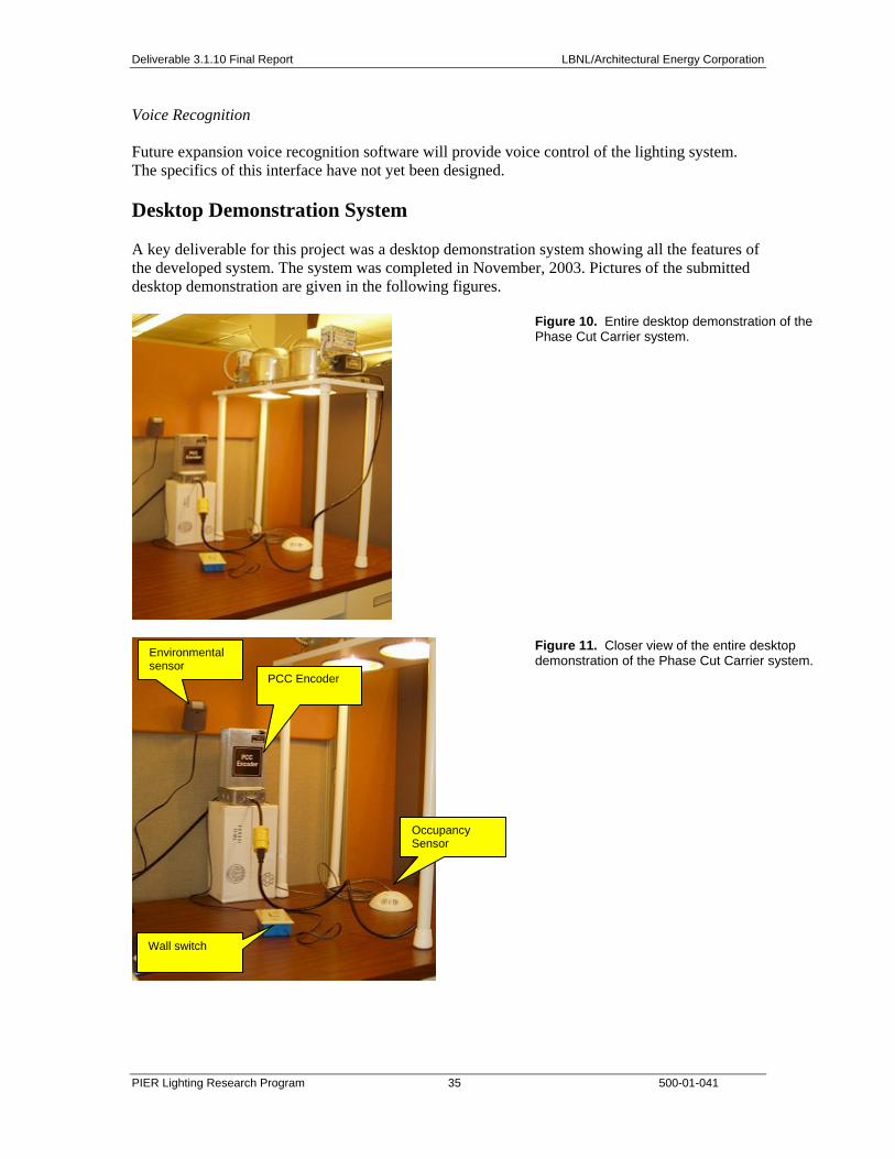
Deliverable 3.1.10 Final Report LBNL/Architectural Energy Corporation
PIER Lighting Research Program 35 500-01-041
Voice Recognition Future expansion voice recognition software will provide voice control of the lighting system. The specifics of this interface have not yet been designed. Desktop Demonstration System A key deliverable for this project was a desktop demonstration system showing all the features of the developed system. The system was completed in November, 2003. Pictures of the submitted desktop demonstration are given in the following figures.
Figure 10. Entire desktop demonstration of the Phase Cut Carrier system.
Figure 11. Closer view of the entire desktop demonstration of the Phase Cut Carrier system. Environmental
sensor PCC Encoder
Wall switch
Occupancy Sensor

Deliverable 3.1.10 Final Report LBNL/Architectural Energy Corporation
PIER Lighting Research Program 36 500-01-041
Figure 12. View of the lights at the top of the desktop demonstration of the Phase Cut Carrier system.
Figure 13. Closeup of the PCC Decoder and the electronic dimming ballast (0-10 VDC) controlled by the system.
Figure 14. Closeup shot of the PCC Decoder showing the electrical connections between the decoder and the ballast.

Deliverable 3.1.10 Final Report LBNL/Architectural Energy Corporation
PIER Lighting Research Program 37 500-01-041
Figure 15. Closer view of the PCC Encoder and attached junction box (which collectively form the “intelligent junction box”). Also shown to the left is the environmental sensor that is attached to the wall. Note the location of the illuminance sensor within the environmental sensor.
The desktop demonstration unit was set up at LBNL in an unoccupied daylit office between July 21st and 30th for testing its overall performance as well as the automatic response to daylight. During this period, the occupancy sensor was disabled and the system was set to run on control mode. The target light level was set to 500 lux with maximum deviation from this target illuminance set to +/-40 lux. The PCC system’s capability as a data acquisition system was exploited to simply data collection. A log file, called “status.log”, is initiated by the PCC software and collected the following information: • Instantaneous wattage • Average wattage • The dimming level recorded as a value between 0 and 7 • Occupancy sensor status: Since this sensor was overridden, sensor data field yields
“occupied” during the test period. • Illuminance level at the multi sensor • Motion sensor status: This sensor’s reading was bypassed. Therefore, although it continued to
collect the occupancy sensor information, this information was not used. • Room temperature recorded in Celsius • Time of day and date Prior to the data collection and analysis of the PCC control system, the data points are studied. Their relevance to the control system analysis is considered below: Instantaneous Wattage Table 2 below shows the instantaneous wattage consumed at eight dimming levels with the corresponding percentage of light output. At minimum light output (25%), the system draws 36.7% of maximum power. This loss in efficacy at full dim is typical of fluorescent lighting systems. The specific locations of the steps in light output are under firmware control. We have elected to make the steps evenly spaced with the minimum level set to 25% light output. Different ranges, step sizes, and step spacing are easily changed by changing the firmware in the PCC Encoder and Decoder. In production, the manufacturer of the ballast would dictate the values of these parameters.
Illuminance sensor

Deliverable 3.1.10 Final Report LBNL/Architectural Energy Corporation
PIER Lighting Research Program 38 500-01-041
Table 2. Instantaneous wattage consumed at eight dimming levels.
Dimming Level Instantaneous
Power (watts) % Light Output
0 18 25 1 21 36 2 25 46 3 28 57 4 32 67 5 38 79 6 42 89 7 49 100
Elapsed Energy Consumption The accumulated energy consumption (in watt-hours) of the lighting circuit fed through the Encoder is indicated in the display. It appears that this annunciator is not properly calibrated for our setup as the accumulated energy consumption was too high by at least a factor of 5. This may be because some parameters are not set correctly. Dimming Level The value of this field varies from 0 to 7 (see table above) and corresponds with the instantaneous wattage fluctuations. Even though the absolute values of the instant wattage are not verified, the synchronous movement of these two values show that the system’s data collection and recording capability are working. Occupancy Sensor Status This occupancy sensor is connected directly to the PCC Encoder. It is intended as a room-based detector. The override placed during the duration of testing forces the value of the data field to “on”. Therefore, the collected data shows that the value of this field is always on. This verifies two issues: 1) the occupancy sensor can be overridden; 2) during the period when the tests were conducted, the occupancy sensor was not an operational part of this system’s control scheme. Environmental Sensor The three following components, specifically illuminance sensor, workstation occupancy detection, and temperature, are all integrated into one device. Illuminance Sensor To test the linearity of the illuminance sensor portion of the environmental sensor, a handheld Minolta illuminance meter is used. The dimming levels are varied in a non-daylit environment and readings are taken at the same point with both the illuminance meter and the multi-sensor. The results are summarized below: Table 3. Results of illumance measurements with handheld meter.

Deliverable 3.1.10 Final Report LBNL/Architectural Energy Corporation
PIER Lighting Research Program 39 500-01-041
Multi Sensor (lux) Minolta (lux) Normalized Multi sensor
Normalized Minolta
Error
128 163 0.267 0.267 0.00 182 234 0.379 0.384 0.00 243 313 0.506 0.513 0.01 294 377 0.613 0.618 0.01 358 455 0.746 0.746 0.00 397 510 0.827 0.836 0.01 435 560 0.906 0.918 0.01 480 610 1.000 1.000 0.00
The normalized values of the multi sensor and the handheld Minolta match closely with 0-0.01 error range. The results show that the sensor responds linearly to changes in light output as expected. Workstation Occupancy Sensor The motion sensor is functioning as specified. The time delay adjustment was 30 seconds during the testing period. The motion detector was temporarily bypassed so it did not interfere with the control system tests. Temperature Sensor A Radio Shack digital thermometer was used to compare the temperature reading of the multi-sensor. Spot measurements concur with multi-sensor readings. Date and Time Stamp The date and time stamp values of the log file coincide with the date and time settings of the computer. Evaluation of Daylight Responsive Element In this test, the PCC control system was evaluated in terms of its ability to respond to the changing daylight conditions and to keep the illuminance at the environmental sensor constant within prescribed limits. The PCC system’s response to variation in indoor illuminance The PCC system can be set to save energy by adjusting the electrical light component, as available daylight increases. To confirm this, the system was set up for automatic control. Using the data logging feature of the PCC system, data was collected in 1-minute intervals. To enable automatic daylight control, the user expands the view of the user interface, checks the “Disable Automatic Controls” box and sets the target illuminance to the desired level. For our test, we used 500 lux that prior measurements in the test room had showed was roughly equal to the maximum daylight level alone. This meant that the room would have enough daylight that the test would be meaningful. Three days of usable data was extracted from the data collected over 9 days. July 24, 25 and 26 were selected for analysis because the motion sensor recorded minimum occupancy for those dates. The power, illuminance and temperature profiles for July 24, 25, and 26 are displayed in Figures 16, 17, and 18.

Deliverable 3.1.10 Final Report LBNL/Architectural Energy Corporation
PIER Lighting Research Program 40 500-01-041
The data confirms that the PCC control system is effective in responding to the variations in the indoor illuminance. The systems starts dimming to maintain 500 lux as the daylight contribution increases. The dimming profile is clean and free of evidences for hunting and spikes. For example, on the 24th, starting at 8:43 am and around 500 lux, the dimming of the system is utilized constantly for 2 hours and 20 minutes. The length of the dimming period iterates the fact that when daylight availability of a space is limited, dimming capability plays a bigger role in the design of lighting systems.
Figure 16A. Lighting power and workplane illuminance July 24, 2004.
Figure 16B. Temperature at the workplane, as measured by environmental sensor, for July 24, 2004
Lighting Power and Workplane Illuminance on 7-25-2004
0
200
400
600
800
1000
1200
1400
1600
1800
6:00 A
M
6:31 A
M
7:02 A
M
7:33 A
M
8:03 A
M
8:33 A
M
9:03 A
M
9:33 A
M
10:03
AM
10:33
AM
11:03
AM
11:33
AM
12:03
PM
12:32
PM
1:02 P
M
1:32 P
M
2:02 P
M
2:32 P
M
3:02 P
M
3:32 P
M
4:02 P
M
4:31 P
M
5:01 P
M
5:31 P
M
6:01 P
M
6:31 P
M
7:01 P
M
7:31 P
M
8:01 P
M
Time of Day
0
10
20
30
40
50
60
Inst
ant P
ower
(W)
Power in Watts (right scale)
Illuminance in lux (left scale)
Figure 17A. Lighting power and workplane illuminance July 25, 2004.
Figure 17B. Temperature at the workplane, as measured by environmental sensor, for July 25, 2004

Deliverable 3.1.10 Final Report LBNL/Architectural Energy Corporation
PIER Lighting Research Program 41 500-01-041
Figure 18A. Lighting power and workplane illuminance July 26, 2004.
Figure 18B. Temperature at the workplane, as measured by environmental sensor, for July 26, 2004
The PCC system’s ability to keep within the target illuminance Figures 16, 17 and 18 suggest that the system is successful in maintaining the 500 lux target illuminance on the work surface where the multi-sensor is located. The system’s response at the end of the day when the multi sensor moves from direct sunlight to sunset as evidenced by the temperature sensor, is even more sudden and a better test. Even when the conditions change abruptly, the system is able to track and respond to these changes as designed. We used the data collected on the log file to calculate the energy savings for each day of the test. Using 6 AM to 6 PM as the hours of operation, the energy savings are 44, 49, and 49% for July 24, 25, and 26, respectively, This shows conclusively that the daylight responsive portion of the control system works correctly, saves significant energy, and reduces light power most during utility peak hours (12 noon – 6 PM). Benefits of Proposed System (Task 3.1.7) Energy and Demand Savings Potential The proposed system saves energy and reduces demand through a number of means, both automatic and manual. A number of case studies of lighting controls in existing buildings have demonstrated the enormous energy savings potential of lighting controls. Lighting controls save energy by exploiting a variety of control strategies, especially: daylight linking, light level tuning, and scheduling. Load shedding is another key strategy for demand reduction. These strategies, and the best available estimate of the energy savings potential of each in a typical building application based on case studies, are given below.
Lighting Control Strategy Strategy Definition Estimated energy savings potential

Deliverable 3.1.10 Final Report LBNL/Architectural Energy Corporation
PIER Lighting Research Program 42 500-01-041
Lighting Control Strategy Strategy Definition Estimated energy savings potential Daylight-linking Automatically lowering electric light
levels in response to increased daylight levels
35% in daylit areas -- 12% averaged over daylit & non-daylit space
Light level tuning Reducing electric light levels according to occupant preferences
25%
Load shedding, demand responsive
Reducing light levels in response to power capacity shortages
N/A. Saves little energy but significant benefits for power generation
Scheduling Turning lights off automatically after space is vacated
25% relative to manual switching
All strategies combined 50% Daylighting. Thirty-five percent savings from daylighting controls in daylit spaces are typical of documented energy savings from available, monitored case studies. For example, the testing at the San Francisco Federal Building indicates that the savings potential from daylighting is between 16-41 percent (estimated annual savings). Since only a fraction of building space is daylit (estimate 35 percent), the 35 percent savings is diluted by 35 percent to obtain average energy savings of 12 percent across all floor space.
Tuning. Measurements at the National Center for Atmospheric Research [Mannicia 2000] suggest that the energy potential of light level tuning is about 15 percent. Measurements of the effectiveness of energy of bi-level switching [Rubinstein 1998] indicate that the savings from tuning could be as high as 25 percent if the switches are well utilized by the occupants. Studies on the energy saving impact on tuning light levels according to spectral content suggest a 25 percent savings from that technique alone.
Scheduling. Occupancy sensors will capture some savings and coupled with the use of intelligent dimming strategies will further increase the energy savings in many applications. LBNL assumed that integrated lighting controls would result in an additional 10 percent energy savings compared to that from occupant sensors alone.
All strategies combined. Based on the case studies, LBNL estimated that an automatic lighting control system combined with the above strategies in the identified target application space has the potential to reduce lighting energy consumption by about 50 percent on average over the year compared to a lighting system of equivalent efficacy that is not controlled.
Although the system is designed for existing buildings, it would be suitable for new construction and would be more economical to install as well, because most of the installation labor charges would have occurred even if a standard lighting system were installed. LBNL estimated: • The target commercial application space for the technology is 4.6 billion square feet in
California commercial buildings. • At present, fluorescent lighting systems in this market consume 21,000 GWhs annually at a
cost to California businesses and institutions of $1.9 billion (in 2000). • The average lighting energy intensity in this sector is 4.5 kWh/square foot/yr. • Using an accepted operating hours of 3200 hours per year, an average power density of 1.43
watts/square foot is imputed. Non-Energy Benefits

Deliverable 3.1.10 Final Report LBNL/Architectural Energy Corporation
PIER Lighting Research Program 43 500-01-041
One benefit of the proposed system is the ability of the occupant to dim their overhead lights to whatever they choose. Although research in this field is sketchy, there is evidence that improved occupant control over lighting and environmental systems in buildings has positive non-energy benefits for occupants in terms of improved comfort and satisfaction with the lighting system. There are many benefits to improved occupant comfort and satisfaction although quantification is difficult:
1. Rental space with added comfort features may command a higher rental value
2. Improved employee retention
3. Accommodation of modern workplace practices such as “hot-desking”, where one workstation is used by more than one individual on different days.
Societal Avoided Costs (for potential incentive payments) Making some assumptions about energy saving potential and the energy intensities in the target sector, the societal avoided energy costs for the project can be computed. First, the energy intensity is obtained by dividing the fluorescent lighting energy consumption in the aggregate total market (21,000 GWh) by the applicable floorspace (4.6 billion square feet in CA).
Energy Intensity: 4.5 kWh/sf-yr Hours of Operation: 3200 hours Imputed Power Density: 1.43 w/sf Energy Savings: 50% Equivalent Power Density Reduction: 0.71 w/sf Time Horizon for Analysis: 5 year
Cost of Avoided Energy
0.09
0.11
0.13
0.15
0.18
0.00
0.02
0.04
0.06
0.08
0.10
0.12
0.14
0.16
0.18
0.20
1 1.25 1.5 1.75 2
Installed Cost ($/square foot)
Avoided Cost ($/kWh)
Figure 19. Cost of Avoided Energy.
From this analysis, LBNL can state that if the new system cost $1/square foot to install, this results in an avoided cost to the end-user of $0.09/kWh. Since that is essentially identical to the
Societal Avoided Cost

Deliverable 3.1.10 Final Report LBNL/Architectural Energy Corporation
PIER Lighting Research Program 44 500-01-041
average societal avoided cost, it follows that no additional utility incentives would be required. However, if the installed cost is, for example, $1.75/square foot, the avoided energy cost to the end-user is $0.15/kWh, considerably higher than the average societal avoided cost of $0.09/kWh. In this case, it would be logical to seek a utility incentive for the technology investment which would “buy-down” the cost of the investment so that effective avoided cost to the end-user was $0.09/kWh. In the example shown, the utility would rebate $0.75 out of the $1.75/square foot total investment (43 percent) to “buy-down” the end-users cost.
Installation-Related Costs The installation of the system requires: 1) replacing the existing ballasts in the ceiling system with dimming ballasts with embedded decoders, 2) replacing the wall switch with the wall control and 3) attaching the encoder to the existing junction box above the wall switch. Each of these steps requires an qualified electrician, but the actual labor activities associated with installing the new system all have analogs in standard practice. In terms of labor expenditure, it should be no more expensive to install a PCC ballast than a standard ballast. Replacing the existing wall switch with a wall control would also be similar in labor cost. Installation of the encoder may the costliest part, since the junction box where the installer would mount the PCC encoder is often above a false ceiling with possibly restricted access. In terms of labor, LBNL anticipates that installing the encoder would be similar to installing another junction box in the ceiling. The Means Cost Guide can be used to estimate all of the above labor costs.
Commissioning costs would likely be incurred in the proposed system. LBNL does not have the necessary information to estimate commissioning costs for the system at this time.
Effects on O&M Cost LBNL anticipates no significant positive or negative changes in maintenance, replacement or repair costs relative to a standard lighting system.
Payback Period and Return on Investment Because the system costs are not yet fixed, LBNL cannot perform a standard payback analysis on this technology. However, armed with estimates of the anticipated energy reduction for the technology, the installed cost can be “back calculated” to determine what amount would have to be to meet to achieve desired payback criteria (two or five year payback, for example). The graphic below summarizes the results of this analysis and plots the target costs for the control system assuming energy costs of $0.08 and $0.15/kWh and payback periods of two, five, seven and 10 years.

Deliverable 3.1.10 Final Report LBNL/Architectural Energy Corporation
PIER Lighting Research Program 45 500-01-041
Target Costs for Control System Assuming Different Payback Times and Energy Costs
0.37
0.921.29
1.84
0.69
1.73
2.42
3.45
0.00
0.50
1.00
1.50
2.00
2.50
3.00
3.50
4.00
2 5 7 10
Simple Payback Period (years)
$0.08/kWh$0.15/kWh
Installed Cost ($/square foot)
Figure 20. Simple Payback for Proposed System.
If the range of “acceptable” installed costs is $1.00 - $2.00/square foot, then the payback for the technology is probably about five years. For the technology to pay back in two years, it would require a target installed cost of $0.37/square foot and $0.69/square foot for energy costs of $0.08 and $0.15/kWh, respectively. It is unlikely that the technology will come down to that price even in a mature market.
Codes and Standards Code-Change Vulnerability: The product’s energy-saving and cost advantages do not depend on any current or scheduled code requirements. If controls credits are still in use in Title 24, then the proposed system should qualify for a number of those credits. If the code changes to eliminate the controls credits, the economics for the end-user would not change significantly. If codes are changed to more of an energy intensity level rather than a power density limit, the proposed technology could benefit from said changes.
Code-Change Dependency: No new code requirements are needed to encourage the adoption of the system. However, a building code requiring dimming ballasts in some applications would be a major stimulant to the proposed technology since the price of the dimming ballast is a major economic hurdle for any dimming system.
The proposed system has built-in energy monitoring capabilities meaning that it could track a building energy usage for code compliance purposes. One possible code change to consider would be providing some sort of credit, if a facility deploys energy monitoring capabilities for a control system. With energy monitoring, codes could be changed to limit kWh rather than just power density.

Deliverable 3.1.10 Final Report LBNL/Architectural Energy Corporation
PIER Lighting Research Program 46 500-01-041

Deliverable 3.1.10 Final Report LBNL/Architectural Energy Corporation
PIER Lighting Research Program 47 500-01-041
Conclusions and Recommendations Recommendations Based on our experience designing and building this ambitious “proof-of-concept” system, we have several recommendations, primarily of a technical nature, for further research and development.
• Add addressing to the Phase Cut Carrier protocol. This would allow decoders with different addresses to be controlled differently by a single encoder. Adding addressibility would increase the number of applications where the control system can be employed since it would increase the number of strategies that can be implemented.
• Implement option to Encoder that would permit the Encoder to control phase-cut style ballasts (aka Mark X) as well as 0-10 VDC dimming.
• Work with ballast companies to explore how to reduce the cost of embedding the PCC decoder into existing 0-10 VDC ballasts
• Work with switch and dimmer companies to explore how to reduce the cost of the Encoder.
Commercialization Potential With the addition of the technical recommendations given above, the integrated lighting control system developed in this project is ready to be commercialized. Because the system developed under Project 3.1 involves various components, more than one type of manufacturer needs to be engaged to provide the necessary resources. The system consists of three basic components: encoder, decoders and wall controls. The decoder has the greatest cost pressure since one decoder is required for each ballast or fixture to be controlled. LBNL will continue to work with ballast manufacturers to obtain realistic estimates as to what the manufacturer’s cost would be to embed the decoder directly into a modern dimming ballast. The wall control is similar to other existing raise/lower wall switches and the cost can be easily estimated. The encoder design has not yet been thoroughly tested so it is premature to perform detailed cost evaluation. Once the design of the encoder has been fixed, LBNL plans to work with a controls manufacturer to obtain a manufacturer’s cost estimate. The cost of the encoder has the greatest uncertainty associated with it. During the course of the project, LBNL held discussions with a number of ballast and control manufacturers concerning their potential interest in adopting the technology. LBNL also prepared a technology transfer brief on the project to distribute to manufacturers and other stakeholders at LightFair. Several manufacturers were engaged in discussion concerning their interest in adopting some or all of the technology embodied in the Integrated Control System. These conversations are described below without identifying the manufacturers. Switch/dimmer manufacturer: Potentially interested in adopting the encoder into their switching product. They would need some modest funding to reduce the cost of the encoder component. Would prefer a non-exclusive licensing arrangement for the Phase Cut Carrier technology. Have concerns with respect to product maintenance. Product is viewed as being

Deliverable 3.1.10 Final Report LBNL/Architectural Energy Corporation
PIER Lighting Research Program 48 500-01-041
complicated and possibly requiring highly trained individuals to provide field support unless the system is extremely easy to install and operate. Integrated control system manufacturer: Potentially interested in a powerline carrier version of the environmental sensor that we use in junction with Integrated Control System. This is an unexpected turn of events that we are examining. Dimming ballast manufacturer: Potentially interested in embedding the Phase Cut Carrier decoder into their new ballast. This would be inexpensive for them to do since their product already sniffs the powerline for superimposed signals. Therefore for them, embedding the decoder could be a zero cost option. There may be patent issues though since the manufacturer has other methods of achieving some of the same performance using IP that they fully control. The lighting market in commercial buildings is primarily static (non-dimming) fluorescent lighting fixtures. Although dimming ballasts are available, they represent only three percent of the total ballast market due to current market conditions and high costs. One barrier to the increased use of dimming ballasts is the lack of a dimming ballast controller that is easy to retrofit into existing buildings. To maximize the penetration of dimming controllers into the market, it should be possible to install the new system without requiring new power circuit wiring or additional low-voltage control wiring. Benefits to California According to Energy Commission data, all lighting energy in all California commercial buildings is 25,000 GWh annually (see Figure 20).
Figure 21. Lighting energy usage for commercial building lighting in California 2000.
Of this total energy expenditure, there is roughly 16,000 GWh/year consumed annually for fluorescent lighting systems in the office, retail, foodstore, schools and colleges building types.

Deliverable 3.1.10 Final Report LBNL/Architectural Energy Corporation
PIER Lighting Research Program 49 500-01-041
Based on our measurements of the performance of the integrated control system in our local facility, the savings potential of using daylighting alone is between 45% and 50% (of course, not all spaces are daylit). Other strategies, such as personal controls, promises an additional energy savings of 15-35% depending on the pre-installation conditions. Assuming that, conservatively, the integrated control system can save 50% energy on average where applied, and that 50% of offices, retail, foodstores and schools adopt the technology, the potential benefit to California business owners is about 50% of 50% of 16,000 GWh, or 4,000 GWh/annually. This value of this energy savings to California energy consumers is $300 million saved annually, just in the State of California. Conclusions This project has demonstrated that it is possible to design an integrated lighting control system that implements all the major lighting control strategies that doesn’t require additional control wiring in the ceiling. The Phase Cut Carrier signaling technology demonstrated in this project shows that integrated lighting controls can be implemented in existing buildings where it is cost-prohibitive to add even low-voltage control wiring to the ceiling. The project also showed the power of implementing a full-fledged lighting control and data monitoring system using a wirelessly-enabled personal computer as the “brains” behind the control system. Although a number of technical hurdles need to be overcome before this is a practical system for manufacturing and deployment, the system shows great promise in bringing the benefits of integrated lighting controls to today’s vast existing building market. The proposed system has the potential to provide energy and non-energy benefits to the State of California and commercial building owners with an acceptable payback period.

Deliverable 3.1.10 Final Report LBNL/Architectural Energy Corporation
PIER Lighting Research Program 50 500-01-041
Appendix A. Guide to operation of the Phase Cut Carrier System Environmental Parameters The maximum ambient temperature allowable for the PCC Encoder 1’s and Decoder 1’s is 55C. The system requires a dry environment without significant condensation, and they are not hardened against shock or high vibration.
Power and Form Factor Requirements The power and form factor requirements for the PCC system are presented below.
1. 277 VAC version of the PCC Encoder 1: Maximum load current 2.4Arms. Supply range is 249 to 305VAC.
2. 120 VAC version of the PCC Encoder 1: Maximum load current 6.0Arms. Supply range is 105 to 134VAC.
Lower line voltages than these will not cause damage to the PCC Encoder 1 or PCC Decoder 1 as long as the current to the load does not exceed the maximum. However, voltages above the maximum may cause permanent damage. To reduce noise that could interfere with PCC communications, the system is to be powered by a branch used only to power lighting. to reduce noise that could interfere with PCC communications. The PCC Encoder 1 is protected by transient suppression located after a 4A (277V system) or 8A (120V system), 250V, 5x20mm, fast blow fuse. All power to the system will be lost if the fuse blows. The fuse should be replaced only with Wickmann 1941400000 (4A) or 1941800000 (8A). Unusually lengthy or high powered transients may cause the fuse to blow, but they typically cause the transient absorbers to remain a short between Line and Return, requiring factory repair. The fuse is located in a fuse holder at the top of the PCC Encoder 1. The 4.6" x 2" top plate must be removed to access the fuse holder. A flat blade screwdriver is required to open the fuse holder by twisting the top of the fuse holder. Short circuits between Line Out and Return of the PCC Encoder 1 may damage the semiconductors or the bypass relay with or without blowing the fuse. To power an occupancy sensor, the Encoder produces 24VDC power. This power is not regulated, but is designed to provide up to 33mA at 19.2 to 28.8VDC. The PCC Encoder 1 is mounted to a 4" x 4" cover plate suitable for use as a lid for a standard junction box. The Encoder’s box is 6” tall, 4.6” wide and 2” thick. The PCC Decoder 1 is mounted to the ballast it controls. The Decoder’s box is 1.5” tall, 2.1” wide and 3.9” long. It has two mounting ears on 3.5” centers with 0.19” diameter holes. Changing Dim Levels A total of eight light levels and off may be selected using the PCC system. These are: 25%, 36%, 46%, 57%, 67%, 79%, 89% and 100% of rated light output. The two momentary pushbuttons on the Pushbutton Control Panel are labeled Brighter and Dimmer. Pressing the Brighter button results in more light output, while pressing the Dimmer button results in less light output. There are special cases at lights off, minimum brightness and maximum brightness. Pressing the Brighter button when the lights are off will turn on the lights at 25%. Repeatedly pressing the Brighter button will cause the lights to get brighter until 100% brightness has been

Deliverable 3.1.10 Final Report LBNL/Architectural Energy Corporation
PIER Lighting Research Program 51 500-01-041
reached. Pressing the Brighter button with the lights at 100% turns off the lights. Pressing the Dimmer button when the lights are off will cause the lights to come on at 100% brightness. Repeatedly pressing the Dimmer button will cause the lights to get dimmer until 25% brightness has been reached. Pressing Dimmer button with the lights at 25% turns off the lights. If the Brighter or Dimmer button is held down for more than one second, the button will begin to auto repeat every half second. Auto repeating buttons will stop at 25% or 100% brightness and will not turn off the lights; but will continue to repeatedly send the 25% or 100% brightness commands every half second for as long as the user continues to hold down that button. Releasing and pressing the same button again after the auto repeat has arrived at 25% or 100% will turn off the lights. The buttons will be recognized if pressed for more than 50ms, and must be released for at least 50ms to be recognized again. The PCC code requires 130 to 200 ms to send the light output commands. If the user is able to command changes in light output more rapidly than they can be sent; the most recently commanded light output will be sent when the next message is started. The PCC Encoder 1 will respond normally to the first button it recognizes if both button are simultaneously pressed. The second button will be ignored until the first button is no longer pressed. A load shedding Dim Level Limit can be set via the Light Controller program that will cap the dim level possible. The present dim level will be reduced to this level if it was above it, and the user will not be able to increase the dim level above this cap. This cap will be lost if the Lighting Controller program is exited and the Encoder is turned off and on. Controlling the Ballasts The PCC Decoder 1's 0 to 10V control output is tuned specifically for the model of ballast delivered with the system and may not produce expected dimming levels for other ballasts. The system can control up to 8 PCC Decoder 1s. This limit is due only to the inductance of the Decoder’s power supply transformer interfering with PCC communication. The PCC Decoder 1’s output performs as if it is a variable voltage with series a 220 ohm protection resistor. Loading by the ballast inputs depends on the type of ballast. The maximum number of ballasts that can be hooked to a single Decoder is generally limited by noise pickup on the 0 to 10V control lines and maximum wattage that can be controlled by the Encoder. The limit due to loads imposed by the ballast control inputs typically is much higher. Occupancy Detection and Control The PCC Encoder 1 will turn off the lights if the room is detected to be unoccupied. The room is considered to be occupied if either the Occupancy Sensor hooked to the PCC Encoder 1 or the motion sensor of the Multi-Sensor is active. The user’s commanded dim level is restored when the room becomes occupied again. The user can over ride faulty occupancy sensors for an hour by commanding a change in dim level from the Pushbutton Control Panel or from the Light Controller program. Commanding the dim level presently in force from the Light Controller program by pressing ON, or clicking on the Level slider’s present position will also activate the occupancy over ride. The occupancy over ride will be cleared if the room is detected to be occupied during the over ride period. The Occupancy Sensor hooked to the PCC Encoder 1 is active if it produces a voltage on the Occupancy In wire of more than 2.5 volts DC. The Occupancy In wire is pulled to ground by a 10K resistor. The PCC Encoder 1 will consider its Occupancy Sensor to be active for 10 seconds

Deliverable 3.1.10 Final Report LBNL/Architectural Energy Corporation
PIER Lighting Research Program 52 500-01-041
after power is applied to the Encoder to allow the Occupancy Sensor time to detect the occupant and pull up the Occupancy In wire. The Multi-Sensor’s motion sensor will report an occupant for up to two minutes after the Lighting Controller program has been started whether there is an occupant or not. The PCC Encoder 1 will timeout the state of the motion sensor to inactive one minute after receiving the last report of activity. This is required to allow autonomous operation when the Lighting Controller program is exited. The unoccupied time delay control on the Multi-Sensor adjusts from a minimum of 30 seconds to a maximum of 30 minutes.
The PCC Encoder 1 produces a courtesy wink if the lights are on and the occupant is no longer detected or the occupancy over ride has ended. The courtesy wink is composed of a half second at full illumination, a half second at minimum illumination and then 10 seconds of the commanded illumination before the lights are turned off. The lights will stay on (or come back on) if an occupant is detected or occupancy over ride occurs. Illumination Control The Lighting Controller program can use the Multi-Sensor’s Illumination Sensor as feedback to regulate the work surface illumination. The user can turn this feature on or off with the Disable Automatic Illumination Control button in the Lighting Controller program. The desired level is set via the Illumination Control Target slider or number entry box. The Lighting Controller program will raise or lower the dim level by 1 every 30 seconds if the measured illumination is not within the Illumination Control Sensitivity setting of the Illumination Control Target. The Lighting Controller program can send “slow dim” commands that cause the PCC Decoder 1 to slew between the present dim level and the commanded dim level at about one dim level per 10 seconds. The user’s dim controls are active in this mode, but the Automatic Illumination Control feature will over ride the user’s dim setting if it produces illumination outside of the desired window. The user or occupancy sensors turning off the lights will over ride the Automatic Illumination Control until the lights are turned back on. Slow dim commands do not over ride the occupancy sensor’s detecting no occupant as the normal Lighting Controller dim commands do. User Option Switch The PCC Encoder 1 has a User Options switch, SW1, located under the cover that has the hole for the BlueWAVE module’s antenna in it. This cover can be removed by removing two screws securing this cover from each end of the Encoder, leaving the bottom cover and end plates in place. The first section of the switch allows selecting between controlling 4-Wire ballasts through PCC codes or 2-Wire ballasts by sending continuous phase cuts. The 2-Wire mode has not been finished and should not be used. The selections are labeled 2 Wire dim and 4 Wire dim. The unlabeled second section of switch SW1 is used to select between Demo Mode timing and Normal Timing. The PCC Encoder normally reports an Average Current value once every 15 minutes. The Light Controller program updates the Energy Consumed and the Wattage and Illuminance graphs each time this report is made. In Demo mode, the Average Current reports are made every minute to show activity, so the Energy Consumed is 15 times the actual value and the Wattage and Illuminance graphs run 15 times normal speed. Demo mode timing is selected by pressing the side of the switch nearest U2. Current Management

Deliverable 3.1.10 Final Report LBNL/Architectural Energy Corporation
PIER Lighting Research Program 53 500-01-041
The PCC Encoder 1 measures the average load current and reports it to the Light Controller program that calculates the Instant Wattage value. The Encoder averages its current reports for 15 minutes (1 minute in Demo Mode) and reports it to the Light Controller program, which calculates the Average Wattage value and Energy Consumed. Auto calibration of the PCC Encoder 1’s zero current measuring error will be done by the PC control program only if the lights are turned off when the program is started and remain off for 30 seconds to allow the PCC Encoder to measure an accurate instantaneous current value. This calibration need only be done once and will greatly improve current measuring accuracy at low current values. Data Gathering The Light Controller program saves data to a log file status.log: Lights on or off, the dim level the lights are commanded to, load shedding limit, Instantaneous and average wattage consumed by the office lighting, occupancy and motion sensor status, occupancy over ride status, hours the room has been occupied that day (reset to zero at midnight), hours the lights have been on that day (reset to zero at midnight), Watt-hours of office lighting used that day (reset to zero at midnight), work surface illuminance, room temperature, PCC Encoder 1 ballast type set by the User Option switch, and maximum dim level possible. The ballast type and maximum dim level possible is labeled as Ballast Type and coded as xxn where xx is the ballast type, 4W = four wire, and n = the maximum dim level possible. Maximum dim level possible is the range of dim levels the Encoder will command if there is no load limit in effect. The time of day and date the readings were captured is also recorded. The PC creates an error.log file for communication errors to the PCC Encoder 1 that include the type of error and the time of day and date it occurred. This can be used to study the integrity of the PC to PCC Encoder 1 wireless link as installed. Status.log and error.log are created in the directory the application was launched from. They are Excel compatible tab delimited ASCII. The these files will be appended to if already existing. The Light Controller program can not update a log file if the user has it open for viewing; but it may be copied at any time for viewing or pasting into an Excel file. It is expected that the computer used to control this system will be run continuously so that it will be available to log data. Column headers are written to the status file, and the Watt-hours of Energy Consumed and Hours Occupied running totals start at zero each time the control program is started. PCC Encoder to Decoder Communication Firmware The PCC Encoder 1 and PC communicate by a Bluetooth serial port. The details of this protocol are described in Section 4. The Lighting Controller program searches for the serial port that the PCC Encoder 1 is attached to. It examines serial ports that the operating system lists as free. When the Lighting Controller program detects the BlueWAVE RS232 to Bluetooth adaptor it will cause it to pair with the Encoder’s BlueWAVE RS232 to Bluetooth adaptor. Once an RS232 link to the Encoder has been established, the Light Controller program attempts to communicate with the Encoder. Lighting Controller status messages indicate which serial ports are being examined, the progress of the Bluetooth pairing and when communication with the Encoder has been established. The Lighting Controller program’s status window displays the status string sent by the Encoder when in Expanded mode. This is used for debugging and development purposes. The class 1 Bluetooth devices used in this system have a typical range of 100 meters. Pressure must not be put on the BlueWAVE module’s antenna that sticks out of the Encoder’s case. The Encoder has a BlueWAVE module LED visible through the antenna cutout in its box. This LED flashes once when power is first applied, flashes continuously while attempting to pair and is on steadily once paired. The PC uses the same type of BlueWAVE module as the Encoder, but it is

Deliverable 3.1.10 Final Report LBNL/Architectural Energy Corporation
PIER Lighting Research Program 54 500-01-041
in a case that may be positioned near the PC and hooks to the PC by a serial cable. This module requires external power from a wall wart supply. PCC Protocol The PCC Encoder 1 can modulate the AC Line Out to the PCC Decoder 1s and the ballasts. PCC, Phase Cut Carrier modulation, is accomplished by selectively turning off the Line Out for the first 60 degrees of conduction after a zero crossing. A combination of phase cuts (ones) and no phase cuts (zeros) are used to send digital codes to the Decoders when a new dim level is to be sent. The Encoder disconnects the Line Out to turn off the ballasts and Decoders. The Encoder’s phase cut modulator dissipates significant energy at higher currents due to its on resistance. The Encoder shorts across the modulator with a low contact resistance bypass relay after 11 seconds of not sending PCC codes. This improves efficiency and reduces cooling requirements. The 11 second period allows the user to make a number of closely spaced dim changes without shortening the relays life time by excessive switching. The Encoder must synchronize to the AC line. It has minimum and maximum values for line frequency and the time it detects the AC line to be near zero, that are used to reject noise. The Decoder differentiates between the no phase cut zero time, the phase cut zero time and rejects noise spikes and brown outs by timing windows. The present implementation of PCC Decoder 1s use transformer based power supplies. The transformers source current during a phase cut and can eliminate the Decoder’s ability to measure phase cuts. The Encoder has a capacitor bank that is hooked across the Line Out when it is ready to send PCC codes. The capacitor switching occurs only at zero crossing to reduce surge currents. The capacitor bank cancels the inductive effects of the Decoder’s transformer so that the phase cuts can be read. It is possible to measure leading power factor while these capacitors are hooked up. The capacitors are only hooked up when a PCC message is about to occur or is in process. The capacitors and associated zero crossing switch will not be required if the Decoders are built into a PFC ballast or if the Decoders are changed to use a switching supply rather than the linear supply. The PCC phase cuts degrade AC line’s THD and Power Factor only while being sent. The effects are similar to those caused by using a lamp dimmer to command a 2-Wire ballast near full light output. PCC code does not introduce a DC offset to the AC line and improves noise detection by sending equal numbers of phase cuts on both AC polarities. Each bit of the message requires two AC zero crossings to encode. The table below represents zero crossings followed by a phase cut with a 1 and zero crossing not followed by a phase cuts with a 0. A start symbol of 01111 is sent to assure synching up to the message even if messages are sent back to back. The LSB is sent after the start symbol and a parity symbol is sent last. A one is represented by 10 and a zero by 01. If successive bits are the same, the repeated symbol 00 is used. The codes may arbitrarily start on the positive or negative phase of the AC line. The AC polarity is not measured by the Encoder or Decoders. A PCC message requires 15 AC half cycles, or 0.125ms plus, minor over head that may occur in the Encoder’s code.
code result phase cuts MSB parity 0 fast dim 0, 25%, least light 01111 01 00 00 00 10 1 fast dim 1, 36% 01111 10 01 00 00 00 2 fast dim 2, 46% 01111 01 10 01 00 10 3 fast dim 3, 57% 01111 10 00 01 00 00 4 fast dim 4, 68% 01111 01 00 10 01 10 5 fast dim 5, 79% 01111 10 01 10 01 00 6 fast dim 6, 89% 01111 01 10 00 01 10 7 fast dim 7, 100%, full light 01111 10 00 00 01 00

Deliverable 3.1.10 Final Report LBNL/Architectural Energy Corporation
PIER Lighting Research Program 55 500-01-041
8 slow dim 0, 25%, least light 01111 01 00 00 10 00 9 slow dim 1, 36% 01111 10 01 00 10 01 A slow dim 2, 46% 01111 01 10 01 10 00 B slow dim 3, 57% 01111 10 00 01 10 01 C slow dim 4, 68% 01111 01 00 10 00 00 D slow dim 5, 79% 01111 10 01 10 00 01 E slow dim 6, 89% 01111 01 10 00 00 00 F slow dim 7, 100%, full light 01111 10 00 00 00 01
The Decoders ignore messages that contain encoding errors or incorrect parity. The previous dim level will be maintained. The system relies on the user or Automatic Illumination Control to re-send the dim level should errors occur. The Decoders require power for a brief period before they can decode PCC when power to the lights has just been turned on. The Encoder sends 0, no phase cuts, for 18 zero crossings, 0.15 seconds, before sending the first PCC message. The ballasts will typically be exhibiting startup behavior when power has just been applied that make this delay irrelevant. The Decoders output 0 volts when power has just been applied but no valid dim level decoded. This commands the ballast’s minimum light level that will be less than dim 0. The Decoder will slew the output voltage to the dim 0 value over about 30 seconds unless a valid dim command is received. The Decoder’s voltage output is tuned for the Mark VII IZT-IT42-M2-LD ballasts used in the LBL demo:
dim 7, 8.2V dim 6, 6.0V dim 5, 5.0V dim 4, 4.1V dim 3, 3.2V dim 2, 2.7V dim 1, 2.0V dim 0, 1.5V
Wiring Wiring for the PCC system is shown below in Figure 4 (will insert full-sheet PDF in final draft). Explanation for this wiring is shown in Table 1 below.
Table 1. Description of wiring for PCC system.
Terminal Encoder Block System wire color pin # wire color use black 1 black AC Line in white 2 white AC Return in orange 3 black AC Line out (jumper to pin 2) 4 white AC Return out (jumper to pin 1) 5 black AC Line to Pushbutton Control Panel, ½ paired zip cord brown 6 black w / white stripe AC signal from Pushbutton Control Panel, ½ paired zip cord red, 22AWG 7 red +24V to Occupancy Sensor blue, 22AWG 8 blue Signal from Occupancy Sensor black, 22AWG 9 black Ground to Occupancy Sensor

Deliverable 3.1.10 Final Report LBNL/Architectural Energy Corporation
PIER Lighting Research Program 56 500-01-041
Decoder Ballast wire color wire color use black black AC Line white white AC Return violet violet 10V+ grey grey 10V- (signal ground)
It is not necessary to ground the case of the PCC Encoder 1 when not hooked to the junction box. Commissioning The PCC system requires commissioning when installed. Calibration values are stored in a file control.ini that is read when the Light Controller program is run. The Expanded User Controls screen is required to commission the system. Nominal office lighting power line voltage is entered in the Lighting Voltage text box. Range checking limits this to between 100 and 500VAC. This value is highlighted in red, as are the Instant Wattage, Average Wattage and Energy Consumed values until the user has updated it from the default value of 120VAC. It is necessary to update this value at commissioning even if 120V is the desired value, which can be done by selecting the text entry box and hitting carriage return. The PCC system requires an Illumination Constant to be entered into the Lux Constant text box. This constant is used to convert Multi-Sensor Vad voltage into LUX. This is set at commissioning because the sensitivity of the illumination sensor is presently in a state of flux. The default is 320 LUX per Volt. This value is highlighted in red, as is the Brightness Sensor value until the user has updated it from the default value. It is necessary to update this value at commissioning even if the default is the desired value, which can be done by selecting the text entry box and hitting carriage return Troubleshooting If the system does not operate, it is possible to isolate the problem to a subsystem. The PCC Encoder 1 can operate independently of the PC under control of the Pushbutton Control Panel. An AC plug is used to connect the switched power out of the Encoder to the Decoders and ballasts. The Decoders and ballasts can be plugged directly into a wall socket and should slowly dim up to 25% light output. A non dimming load can be plugged into the Encoder’s switched power output to verify it can power a load. Occupancy sensors turning off the lights can always be over ridden by manually changing the dim level, though the over ride will end if the occupancy sensors briefly report occupancy. The PCC Encoder must be synchronized to the AC line frequency to operate properly. If it can not synchronize due to poor power quality or noise, the following symptoms will occur:
- The lights will not turn on or off and will not change dim level. - Commands from the wall switch will have no effect. - Commands from the PC will not cause the light to turn on or change dim level, but the
status reports will indicate that the commanded change has occurred. The Instant Wattage and Average Wattage will be 0, or very close to 0, even when the lights are commanded to be on.
- The Occupancy sensor is always reported as ON (the power up condition) or the last state if synchronization is lost after power up.
- Occupancy Override from the Lighting Controller program can occur and be reported by status, but will never time out or be cleared by the Motion Sensor coming back ON.
- The Multi-Sensor is fully functional.

Deliverable 3.1.10 Final Report LBNL/Architectural Energy Corporation
PIER Lighting Research Program 57 500-01-041
The Bluetooth communications components were intended for use over distances typically found when used in an office environment. Bluetooth communication may fail if the PCC Encoder 1 is placed within a few feet of the PC’s Bluetooth transceiver. If communication failure occurs, the Light Controller program will search all serial ports for a Bluetooth link to the PCC Encoder 1. It may find the Bluetooth link and fail to connect and resume searching ports. Try moving the system components further apart, or removing the antenna from the PC’s BlueWAVE module. The use of USB to Serial converters can compound other system problems. A USB to Serial converter should not be used for the Bluetooth link due to excessively slow operation when finding the Bluetooth link. This same slow operation will occur if a USB to Serial port converter is present in the system and that port is searched. The USB’s Com port should always be a higher number than a real serial port, so it should never be searched for a Bluetooth link by the Lighting Controller program in normal operation. If the converter is present in the system, used for the Multi-Sensor for example, it will cause the Light Controller program to hang up for minutes searching the USB to Serial converter’s Com port should the Light Controller program not find the Bluetooth link on the first attempt, or lose communication. The Light Controller program can not be exited by clicking on the red X while in this condition. Using the task manager to end the program will corrupt the operating system so that the Lighting Controller program can not be successfully run until the PC has been re-booted. If the PCC Encoder has received a change of dim command, the bypass relay can be heard to click off immediately and back on in about 11 seconds after the last command is issued. This confirms the Encoder received the command even if the light output does not change due to other problems. The Mark VII ballasts will output 100% light if either control lead is disconnected. The ballasts will output approximately 5% light output if the control leads are shorted together. Disconnecting the power to a PCC Decoder 1 will cause the controlled ballast to go to its minimum light output of approximately 5%. The PCC Encoder 1 does not detect the power up of a PCC Decoder 1 and re-send the light output command. Turning off power to individual PCC Decoders will cause them to be out of synch with the rest of the system until the next command is sent. The system cannot be powered through a lamp dimmer as it will interfere with PCC communications. The PCC Encoder 1 and PCC Decoder 1 modules are rated to operate up to 55C ambient. Excessive heat can cause temporary or permanent malfunction. Brown outs may cause some system components to exhibit power up behavior, while other components may continue in their previous state. The PCC Decoder 1s are typically less likely to be affected by a brown out than the PCC Encoder 1. It is normal ballast behavior to briefly flash to full brightness upon power up. This will occur even if the power up command is 25%, because the command input is ignored during this flash. The ballasts shipped with this system can take many seconds to achieve significant light output if they have not been run for a long time. If the system is first turned on while the occupancy sensor and motion sensor are not detecting an occupant, pressing a dim button to set the light level while the system is timing out the power up default occupied status will not cause occupancy over ride to occur. This is because the Encoder believes the room is occupied. Once the power up default occupied state has timed out, the Encoder will consider the room to be unoccupied and turn off the lights if the user does not change dim levels during the courtesy wink timing.

Deliverable 3.1.10 Final Report LBNL/Architectural Energy Corporation
PIER Lighting Research Program 58 500-01-041
The PCC Encoder 1 and PCC Decoder 1 modules use transformer isolated power supplies. The AC switching output and transient protection of the PCC Encoder 1 is not transformer isolated. The PCC Encoder 1’s isolated ground is hooked to the Occupancy Ground output. The PCC Decoder 1's ground is connected to the Grey wire 10V- output. Holding a button in auto repeat even after the system has been commanded to minimum or maximum light is a way to cause PCC commands to be issued every 1/2 second. Over heating may occur if this is done for a long time at a substantial fraction of full load as the bypass relay will not engage.

Deliverable 3.1.10 Final Report LBNL/Architectural Energy Corporation
PIER Lighting Research Program 59 500-01-041
Appendix B. Firmware Documentation for Phase Cut Carrier Encoder
SYSTEM COMMUNICATIONS OVERVIEW The office PC and the local PCC Encoder 1 communicate by RS232 that is transmitted via
BlueWAVE RS232 to Blue Tooth adapters. The PC sends commands to the PCC Encoder 1,
which returns status to the PC. The status returned will allow verifying that the PC’s commands
have been received. The PCC Encoder 1 will spontaneously send status about once every 15
minutes when it has new average current values to report. The PC must initiate a connection
between the BlueWAVE module it is hooked to and the BlueWAVE module in the PCC Encoder
1 before it will be able to send commands or receive status.
RS232 RS232 settings are 115,200 Bits Per Second, 8 Data Bits, No Parity, 1 Stop Bit,
Hardware Flow Control.
ASCII The data is ASCII. The left most character in commands or status is sent first.
Null, 00 hex, must never be sent as it is interpreted as no character received by
the PCC Encoder 1’s firmware. The characters are case sensitive.
Blue Wire The PC must initialize the BlueWAVE DTE unit that is connected to the PC’s
RS232 port to establish a wireless connection to the BlueWAVE DCE unit in the
PCC Encoder 1. No other Blue Tooth master devices may connect to the PCC
Encoder 1’s DCE while the PC’s DTE unit is connected. The PIN # of the
BlueWAVE DCE module is 1111. The address of the local PCC Encoder 1 must
be discovered after installation while no other unknown Blue Wire devices are
within RF range of the PC’s DTE unit.
DATA Mode
On power up the BlueWAVE RS232 Wireless Cable units will be in DATA
mode. In this mode, all data passed from one BlueWAVE module will be sent
through the other BlueWAVE module to the RS232 port and vice versa once it
has been connected. The power up condition is that the BlueWAVE module is

Deliverable 3.1.10 Final Report LBNL/Architectural Energy Corporation
PIER Lighting Research Program 60 500-01-041
not connected to any other BlueWAVE modules. Once connected, the
BlueWAVE units act as a cable, but only if the specified RS232 settings are used.
COMMAND Mode
COMMAND mode is used to configure and control the PC’s BlueWAVE module. COMMAND mode can be entered by sending three consecutive ASCII ‘+’ characters which are more than 100ms apart over the RS232 interface. In command mode, no data is received from the remote Bluetooth device. Data entered on the local RS232 interface is passed to the local BlueWAVE unit. This implementation is consistent with most modem interfaces. The Configuration commands are listed below. The configuration, other than establishing the connection, is stored in the BlueWAVE DTE’s non volatile memory and will only require setup once. The factory default configuration of the BlueWAVE DTE units are 115200 baud, no parity, 1 stop bit and 8 data bits.
Configuration Commands
The following commands can be used to connect with or configure the BlueWAVE DTE device. Simply send the command as shown, then a carriage return, and an ‘OK’ or ‘ERROR’ string will be returned to indicate success.
Commands required to connect to the PCC Encoder 1 after each power up of the PCC
Encoder 1 or the PC.
COMMAND FUNCTION
+++ Place local BlueWAVE DTE in command mode. No status or
echo returned. Separate +s by 0.1 second or more.
AT+BWI
Discover available Blue Tooth devices to connect to. Status
returns the ID of available devices, followed by “OK” on the
next line. The local PCC Encoder 1’s expected address will be
discovered if it is operating correctly. Other PCC Encoder 1’s
within RF range will also be discovered, but should not be
connected to.
AT+BWC=address,PIN#
Connect to the PCC Encoder 1’s DCE. The address is the value
returned by the AT+BWI status for the desired PCC Encoder 1’s
DCE, followed by a “,” and then the PCC Encoder 1’s DCE
PIN# which is a default of 1111. There will be a status of
“CONNECT” returned after a significant delay, when the PCC
Encoder 1’s DCE has connected.
AT+BWE Exit COMMAND mode – return to DATA mode. Required to

Deliverable 3.1.10 Final Report LBNL/Architectural Energy Corporation
PIER Lighting Research Program 61 500-01-041
send data to the PCC Encoder 1 after connecting. Status of
“OK” will be returned.
Configuration Commands, not required for connection.
COMMAND FUNCTION
ATE0 Turn local echo Off
ATE1 Turn local echo On
AT+BWB=0 Set baud rate to 1200 baud
AT+BWB=1 Set baud rate to 2400 baud
AT+BWB=2 Set baud rate to 4800 baud
AT+BWB=3 Set baud rate to 9600 baud
AT+BWB=4 Set baud rate to 19200 baud
AT+BWB=5 Set baud rate to 38400 baud
AT+BWB=6 Set baud rate to 57600 baud
AT+BWB=7 Set baud rate to 115200 baud
AT+BWB=8 Set baud rate to 230400 baud
AT+BWP=N Set Parity to None
AT+BWP=O Set Parity to Odd
AT+BWP=E Set Parity to Even
AT+BWS=1 Set Stop Bits to 1
AT+BWS=2 Set Stop Bits to 2
Information Commands, not required for connection.
COMMAND FUNCTION
ATI3 Display the BlueWAVE Model
ATI6 Display the firmware version
ATI8 Display the date of software build
ATI9 Display the country of manufacture
Control Commands, not required for connection.
COMMAND FUNCTION
AT+BWN=nnnn Set Bluetooth™ PIN to nnnn. Pin should consist of between 4 and
8 characters
AT+BWZ Allow the unit to go into sleep mode.

Deliverable 3.1.10 Final Report LBNL/Architectural Energy Corporation
PIER Lighting Research Program 62 500-01-041
AT+BWM=xxxx Set the Bluetooth™ unit name. The name is the identity by which
the device is seen by other Bluetooth™ systems. This does not
effect the Bluetooth™ address.
PCC ENCODER 1 COMMAND SET
Dim levels
fx, sx, and mx commands and the dx and cx status refer to dim levels. The dim level relates to
light output as follows for PCC Decoder 1s (4 wire, 0 to 10V) and Phase Cut (2 wire) ballasts:
dim f, 0% of rating, ballast receives no AC power, is off.
dim 0, 25% of rating, least illumination
dim 1, 36% of rating
dim 2, 46% of rating
dim 3, 57% of rating
dim 4, 68% of rating
dim 5, 79% of rating
dim 6, 89% of rating
dim 7, 100% of rating, full illumination
PCC Decoder 2s (step dim) will use dim 0 as their least bright setting that is on, plus as many
higher dim settings as are available from the ballasts. The upper limit may be set by the PC
with the mx command in the general case, or can be hard coded in the PCC Encoder 1 in
custom systems.
Commands from PC
Command Characters
fast dim f0 … f7, ff
slow dim s0 .. s7, sf
maximum dim m0 … m7
encoder status bad eb

Deliverable 3.1.10 Final Report LBNL/Architectural Energy Corporation
PIER Lighting Research Program 63 500-01-041
The PC must not over run the PCC Encoder 1’s RS232 receiver. Hardware flow control is
used to tell the PC to stop sending characters after each character received by the PCC
Encoder 1. The flow control will enable to the PC to send more characters when the PCC
Encoder 1 has room to receive them and has finished any status report in progress. The PCC
Encoder 1 will honor hardware flow control commands sent by the PC. Each PC command is
two ASCII bytes with no carriage return or line feed. The PCC Encoder 1 will respond to
each received command with a status string.
fx PC command will cause the PCC Encoder 1 to command the PCC Decoders or
Ballasts to go to the specified dim level or turn off. The response will not be
deliberately delayed beyond the fraction of a second required for noise filtering and
the time to send the message by PCC to the PCC Decoders if any. fx will over ride a
previous dim level set by the user’s wall switch or the PC. If the PCC Encoder 1
detects that the room is unoccupied an fx and will cause the same occupancy sensor
over ride as if the user had pressed a wall switch button. Each command re-starts the
occupancy over ride timer. The lights will be turned back on for one hour if they had
been turned off due to an unoccupied room. Turning off the lights with an ff or by
the wall switch will abort any occupancy sensor over ride in process. No action other
than issuing a pb status will occur if the PC attempts to command a dim level higher
than the maximum allowed as reported by the cx bytes of the status report.
sx PC command will cause the PCC Encoder 1 to command the PCC Decoders to slowly
slew to the newly specified dim level. Used to command new dim levels as part of a
light regulation or daylight harvesting control system. The rate of change is about 10
seconds per dim level change for ballasts controlled by PCC Decoder 1s. This rate of
change is not easily noticed by the room’s occupant. Phase Cut (2 wire) ballasts and
PCC Decoder 2s (step dim) will respond to this command without delay, as if it were
a fx command. sx will over ride a previous dim level set by the user’s wall switch or
PC, and it is the PC’s responsibility to restore the user’s dim level if light regulation
is turned off, and to notice if the user increments or decrements this level. Light
regulation is over ridden by the room being unoccupied. The sx command will be
illegal if the lights are off due to the PCC Encoder 1’s occupancy sensor indicating
that the room is unoccupied. The sf command will not abort the occupancy sensor
over ride time as the ff command does. The sx commands do not restart the

Deliverable 3.1.10 Final Report LBNL/Architectural Energy Corporation
PIER Lighting Research Program 64 500-01-041
occupancy over ride timer if in process. Because 0 is the minimum dim level that can
be commanded, the sf command causes the PCC Encoder 1 to turn off the ballasts
without delay. The PCC Decoder 1s slew between their present 0 to 10V output and
the target 0 to 10V output at the slew rate. They will pass through light levels
between the defined dim levels while slewing; but the target dim level will be a
defined dim level. Changing the dim level with a new sx command while slewing
will update the target to the last commanded value and can change the direction of
the slew. Sending an fx command will cancel any slewing in process and cause the
new fx command to be applied without delay. Changes due to an mx command can
over ride the target of a slew in process, but will not cancel slewing. No action other
than issuing a pb status will occur if the PC attempts to command a dim level higher
than the maximum allowed as reported by the cx bytes of the status report.
mx PC command limits the dim level set by the user’s wall switch and PC commands.
The PCC Encoder 1’s present dim level will be reduced to this value if it was set to a
higher light output. This can be used to achieve load shedding. The PCC Encoder 1
will forget this value if it loses power. The PCC Encoder 1 will not remember the
previous dim level setting if it is reduced by the mx command so PC should
remember and restore the user’s dim level after the end of the load shedding when the
PC raises the mx limit. The mx commands do not affect the occupancy over ride
timer if in process. If the PC is turned off while in load shedding, the PCC Encoder 1
may still have a dim limit imposed by the mx command when the PC is turned back
on after load shedding is over. The status bxx and cx allow detecting this condition
so that it can be corrected by sending the maximum allowed mx command. mx
commands greater than the default maximum dim level as reported by the bxx status
will not be allowed.
eb PC command will cause the PCC Encoder 1 to send its present status. The PCC
Encoder 1 has no further error recovery behavior in response to this command, so it
may be used to request status.
Status from Encoder
Status Characters

Deliverable 3.1.10 Final Report LBNL/Architectural Energy Corporation
PIER Lighting Research Program 65 500-01-041
dim level d0 … d7, df
occupancy sensor on, off, on , of, oo
over ride
Ballast is Phase Cut, PCC bpx , bcx where x is the maximum dim level, not
changed by mx limit.
instant mA ixxxx , where xxxx is current in mA
15min average mA axxxxtx , where xxxx is current in mA, and x is
relative time counter 0 to 7.
cap on dim level c0 … c7 where x is the maximum dim level that
can be commanded.
PC command bad pb sent instead of above status lines if a bad
command has been received.
delimiter <space> separates symbols.
end of message <cr lf> terminates status.
All status messages in response to a valid PC message will contain “dx ox bxx ixxxx
axxxxtx cx <cr lf>”.
dx status reports the dim level presently in force. This dim level will be the final dim
level while the PCC Decoder 1s are slewing to a final dim level in response to an sx
command. The PC can figure out the approximate light output while the PCC
Decoder 1s are slewing by reading the instantaneous current or calculating that the
rate of change in response to sx commands is about 10 seconds per dim level. User
light level input from the wall switch will act as if an fx command has been sent. It is
expected that light level regulation will not send changes in dimming of more than
one dim level, or faster than the PCC Decoder 1s can slew to the new level. Failure
to follow these constraints could result in confusion if the user changes dim level
based on the target dim level, not the instantaneous dim level, should they be more
than one dim level apart. The PCC Encoder 1 will default to ballasts off after power
up. When the occupancy sensor has turned off the light, as indicated by status “of”,
the dim level reported is the one that will be in effect if the occupancy sensor turns
the lights back on. The dim level not equal to “df” does not indicate that the light is
on if the occupancy status is “of”.

Deliverable 3.1.10 Final Report LBNL/Architectural Energy Corporation
PIER Lighting Research Program 66 500-01-041
ox status reports the PCC Encoder 1’s occupancy sensor state. “on” will be returned
while the occupancy sensor is detected to be on or has not been debounced for more
than 10 seconds in the off state. The occupancy sensor is assumed to be “on” after
the PCC Encoder 1 has been powered up till after the debounce period has expired.
If the occupancy sensor state is “of”, or a courtesy wink in process, the status will be
“of”. If the occupancy sensor has been over ridden by f0 .. 7 commands from the PC
or user dim 0 .. 7 commands from the wall switch, the status will be occupancy
sensor over ride, “oo”. Occupancy over ride state lasts about 1 hour after the last
over ride.
bxx status reports the type of power line communication in use and the maximum dim
level allowed by the PCC Encoder 1’s firmware. The type of power line
communication is selected by the PCC vs. Lamp Dimmer dip switch in the PCC
Encoder 1. bpx indicates that the PCC Encoder 1 is in Phase Cut, 2 wire, continuous
dimming mode. This selection is tuned for use with Advance Mark X ballasts and
does not require PCC Decoders. bcx indicates that the PCC Encoder 1 is in Phase
Cut Carrier, PCC, 4 wire, 0 – 10V mode. Phase cuts are sent only during commands
from the PCC Encoder 1 to the PCC Decoders. The type and tuning of PCC Decoder
must match the ballast it controls. The standard maximum dim level reported is 7.
Customization of the PCC Encoder 1’s firm ware is required to change this. This
value is the maximum allowable dim level that can be set by the mx command.
ixxxx status reports the last reading of the instantaneous current consumed by the ballasts
under the control of the PCC Encoder 1. New readings are taken approximately once
per second and are averaged over about a second before being digitized. This
represents the average of the current waveform after it has been full wave rectified,
not the RMS value. The PC can calculate the RMS value from this average if the
load draws sinusoidal current as is typical of 4 wire, 0 – 10V ballasts above the lower
dim levels. For sine waves: Vrms = Vave * Pi / (2 * sqrt(2) ). Power consumption in
Watts is the RMS line voltage times the RMS current. Good accuracy converting
average to RMS when controlling 2 Wire ballasts and all ballasts at low light level
will require calibration software in the PC. The PCC Encoder 1 does not presently
do any calibration of the current readings for zero current offset, gain or linearity to
improve the accuracy of the average value it measures. Better accuracy of the current

Deliverable 3.1.10 Final Report LBNL/Architectural Energy Corporation
PIER Lighting Research Program 67 500-01-041
reading can be obtained by calibrating the zero current offset with the load off (can
be done without user assistance), and the gain / linearity at each dim level with the
aid of an RMS current meter. The current reading accuracy is good enough to assure
that it is monotonic, and the best accuracy is achieved at the higher dim levels. The
current is reported in 2s complement with the least significant bit equal to 1mA.
Zero current offsets can result in negative current values being reported, but ideally
only positive current values should be reported due to the absolute value process in
the PCC Encoder 1 hardware. Treat negative current values as being the result of an
offset error. Changing their polarity is not a correct way to calibrate negative values;
clipping them to zero would be preferred if they can not be calibrated out. It is
expected that negative current values will not occur when at least one ballast is
turned on and commanded to a dim level above off. Only the lower 13 bits of the
current value are used for magnitude. The sign is extended across the remaining bits
13 .. 15. The current is digitized by a 12 bit A/D, with ideally no values in the
negative half of the range. The ideally 11 bits are scaled to the desired 1mA LSB
which requires 13 bits to represent. The current value is hexadecimal ASCII, not
BCD or true binary. Possible current values that will be reported are +/- 6.649A if no
calibration occurs in the PCC Decoder 1. The maximum possible current values that
can be represented in 13 bits are -8.192A to 8.191A, E000 to 1FFF.
axxxxtx status reports an average of the ixxxx current values. The average is updated
about every 15 minutes, with new samples added to the average about every second,
1024 samples total. This averaging process significantly improves the accuracy and
resolution of the axxxx value above the ixxxx value if the load is constant during the
averaging period. The value reported by axxxx is the last 15 minute average that has
been completed, so it could be out of date by up to 15 minutes. The value reported
before the first average has been accumulated after power up is 0. This is not a
running average, the average starts over each 15 minute period. The tx portion of
axxxxtx identifies which 15 minute period is being reported. The x in tx can be 0 to
7, starting at 1 after power up, incrementing after each average has been
accumulated, and rolling over to 0 after 7. The axxxxtx value will be reported every
15 minutes. It is possible for the report requirement to be satisfied through a status
report in response to a command from the PC. The tx value allows detecting this
condition. The tx value can be used to tell when a new average has been completed

Deliverable 3.1.10 Final Report LBNL/Architectural Energy Corporation
PIER Lighting Research Program 68 500-01-041
if the PC polls for 15 minute average current status rather than relying on
spontaneous reporting of this value. If the PC is off, or tells the PCC Encoder 1 to
stop sending data, for more than about 2 hours there is potential for confusion as the
tx number may be the same as that sent before communication was stopped, but will
represent a different sample. An unsent average is replaced by the most recent one,
not qued for sending.
cx status reports the maximum allowed dim level in force. This is the default maximum
dim level reported by the bxx status unless changed by the mx command. The PC
must use the mx command to raise the maximum allowed dim before commanding
dim levels above the cx dim level.
pb status reports that the last two characters received by the PCC Encoder 1 were not
interpreted as a valid command and no additional action has been taken. The PC
should re-send the last command. Improper command syntax, illegal commands or
communication errors will cause a status of “pb <cr lf>”. If this condition persists, it
may be due to an extra character being received, or a missed character. Noting that
the pb response occurs after what the PC considers to be the first character of a two
byte command detects this out of synch condition. The out of synch condition can be
corrected by sending any illegal character, such as $, which will cause the pb status
and ready the PCC Encoder 1 for the next valid command

Deliverable 3.1.10 Final Report LBNL/Architectural Energy Corporation
PIER Lighting Research Program 69 500-01-041
Appendix C. Instructions for Making an Environmental Sensor
1. Set the Time Delay control to Max. Remove the top lid from
base and the electronics. This is accomplished by placing the unit with the top of the lid (side with the translucent window, and LED light pipe showing) in the palm of one hand and insert a small screw driver into the crack between the lid and the base near the translucent end. Avoid breaking the tabs (just above the screwdriver in the photo) in the lid when inserting the screwdriver. Open the translucent end by prying, and then carefully separate the lid from the base starting at the translucent end and not losing the Time delay knob, which may stay with the top lid.
2. A TAOS TSLG257 photo sensor is to be mounted on a mounting plate, which will be mounted to the RJ-11 jack of the occupancy sensor. Cut the mounting plate from 0.07” thick plastic. Use a #41 drill to make a hole for the photo sensor’s visibility and mill a slot to accommodate a ridge on the photo sensor. See file “Mounting Plate.pdf” for a to scale version of the drawing shown here.
3. The photo sensor must be mounted on the correct side of the mounting plate. The
photo sensor’s pin 3 must be next to the outer edge of the mounting plate. Trim the sensor leads to about 0.35” from the body of the photo sensor. When the correct side of the mounting plate has been identified, align the bump on the top side of the photo

Deliverable 3.1.10 Final Report LBNL/Architectural Energy Corporation
PIER Lighting Research Program 70 500-01-041
sensor in the hole of the mounting plate and place the sensor’s ridge in the slot. Clamp with an alligator clip and apply epoxy around the periphery of the photo sensor. Keep the sensor’s face very flat against the bottom of the mounting plate to preserve aim.
4. Extract the board from the bottom lid of the occupancy sensor by prying with a screw driver under the board near a retention arm.
5. Cut traces to pins 3 and 4 of J1 on the
top side of the board. See photo for locations. CUT1 & 2 on schematic. 6. Drill a #41 hole in PCB to allow running wires to the bottom side of the board. The
hole should be located approximately on a line between R5 and J1 intersecting with a line from C11 to VR1, as indicated in the photo. Avoid all traces.
7. When the photo sensor to mounting plate epoxy has dried, epoxy the sensor and mounting plate to the occupancy sensor board’s RJ-11 jack J1. The mounting plate must align with the edges of the RJ-11 jack on two sides. See photo for orientation

Deliverable 3.1.10 Final Report LBNL/Architectural Energy Corporation
PIER Lighting Research Program 71 500-01-041
and alignment. Make the photo sensor’s front face upwards, away from the board’s surface. Keep the mounting plate very flat against the RJ-11 to preserve aim.
8. The RJ-11 jack J1 on the board has pin numbers 1 and 6 etched in copper on the back side of the board. These pin numbers are the opposite of the usual numbering convention, but will be used in this document. See photo for all RJ-11 pin numbers.
9. The Dallas Semiconductor / Maxim DS2438Z’s pin 1 can be identified by referring to the photo and noting the orientation of the writing on its top surface. The writing is difficult to see under most lighting conditions and viewing angles and may require magnification.
10. Epoxy the DS2438Z to the board approximately in the location shown in the photo. Be careful not to get epoxy on the chip’s leads. See successive photos for sample wiring. The added parts are documented in the schematic “Multi-Sensor Added Parts.pdf”.
11. Wire “jump 1” from J1 pin 2 on the bottom side
of the board to the photo sensor, TSLG257, U802 pin 2 on the top side with red 30AWG wire.
12. Wire “jump 2” from U802 pin 2 to U801, DS2438Z, pin 5 on the bottom side with red 30AWG wire.
13. Wire “jump 3” from the positive pin of C15 to Test Point 8 on bottom side with orange 30AWG wire.
14. Wire “jump 4” from J1 pin 1 to J1 pin 3 to J1 pin 5 on the bottom side, to R801, 10K 1/8W 5%, pin 1 on the top side with black 30AWG wire.
15. Trim the leads of R801 pin 2 and R802, 22K, 5%, 1/8W, pin 2 to about 0.2”, bend to 90 degrees near their bodies and solder them together. See photos. Note that the pin 1 or 2 designation of resistors is arbitrary.
16. Wire “jump 6” from R801 pin 2 to U801 pin 2 on the top side with white 30AWG wire. 17. Wire “jump 7” from U801 pin 3 to C801’s “–“ pin with an inch long black 30AWG wire.
Solder to C801 near C801’s body. 18. Trim the leads of C801, 10uF, 6V or more, tantalum or ceramic capacitor as required
to wire C801’s positive pin to U801 pin 4 and C801’s negative pin to U801 pin 1. See photos for the desired result.
19. Wire “jump 5” from R16 pin 2 to U802 pin 1 to C801’s “+” pin with Black 30AWG wire. Melt off some insulation at U802 to allow the intermediate connection.
20. Wire “jump 8” from Test Point 18 on the bottom side to R802 pin1 on top side with white 30AWG wire.
21. Epoxy R801 and R802 to the top side of the board. See photos for approximate location.
22. Wire “jump 9” from J1 pin 4 on bottom side to U801 pin 8 on top side with yellow 30AWG wire.
23. Trim the leads of R803, 22K, 5%, 1/8W to about 0.15”. 24. Hook R803 pin 1 to C801’s “+” pin on the top side of the board, with R803’s body
aimed toward U801 pin 5.

Deliverable 3.1.10 Final Report LBNL/Architectural Energy Corporation
PIER Lighting Research Program 72 500-01-041
25. Wire “jump 10” from R803 pin 2 to U802 pin 3 with a white 30AWG wire on top side of the board.

Deliverable 3.1.10 Final Report LBNL/Architectural Energy Corporation
PIER Lighting Research Program 73 500-01-041
26. A plastic light shield and aperture glued directly to the top of the mounting plate were
used when some of these photos were taken. The light shield curved under the sensor has been replaced and the aperture is now taped to the underside of the top lid as described later.
27. Silicon light shield: Completely cover the back side and exposed side of the photo sensor with a blob of black silicon. Also cover the slot above the sensor, but be careful not to get silicon elsewhere on the mounting plate’s top surface, especially over the sensor’s optics.
28. The Multi-Sensor requires 5V power on pin 1 of its RJ-11 to operate. The recommended solution is to use an AAG DS9097U-S09, RS232 1-Wire adaptor for a DB9 serial port that provides the required 5V power and has the same pin out as the Multi-Sensor. Note that Dallas Semiconductor

Deliverable 3.1.10 Final Report LBNL/Architectural Energy Corporation
PIER Lighting Research Program 74 500-01-041
adaptors of the same part number do not provide the required 5V power. The AAG part is labeled with a single line of text “9097U-S09-X”, while the Dallas part has three lines of text on its label. See www.aagelectronica.com to purchase. A 4 conductor, non flipped, RJ-11 cable is required to connect the Multi-Sensor to the AAG DS9097U-S09. Make sure the cable connects pin 1 to pin 1, through pin 4 to pin 4. Some commercially available “phone” cables swap pins.
RJ-11 pin # 1 5V 2 GND for 5V 3 1-Wire Data 4 1-Wire GND
29. Drill a letter B hole in the lid, approximately ½” from the inside of the rear lip curved edge (end with time delay knob) & 0.05” to the left of the centerline marked by the “+” embossed mark (on the underside of the lid) using a drilling guide that exactly positions the hole above the center of the installed sensor.
30. A 6 MM ground glass diffuser Edmund Scientific part number NT45-650. See www.edmundoptics.com to purchase. The diffusing surface must face the outer surface of the lid. Press the diffuser into the hole in the lid made by the letter B drill bit such that the diffusing surface is far enough below the top surface of the top lid to prevent undiffused light leaks. Do not press the diffuser in far enough that the bottom of the diffuser extends past the underside of the lid. Tape on the underside of the diffuser, or epoxy coating the hole, may be used to secure it in place if the press fit is not sufficient. Do not use superglue as it can fog the optics. Use non-yellowing tape for this and the following procedure.
31. An aperture is used to restrict the amount and angle of light falling on the photo sensor. Precision apertures with the required high density opaque area are available from LANmark Circuits. The size range is 0.015 to 0.0395” diameter in 0.5 thousands increments. See quote to order. Due to the large variation in component sensitivity it may be necessary to select the aperture size for each unit individually. The aperture can be selected by trial and testing vs. a reference unit. Each trial will require temporarily affixing the aperture with tape and reattaching the top lid. LBL must determine the allowed error to end the selection process. Note that any misalignment of the optical sensor, aperture or diffuser hole will affect unit sensitivity. 25 thousands is the recommended starting point, but may change with different sensor lots.
32. The aperture must be cut out of the sheet and taped over the bottom side of the diffuser on the underside of the lid. The aperture’s hole must be centered with respect to the diffuser. The aperture has quadrant marks that will be of assistance in centering if an X is drawn through the center point of the diffuser hole. Tape the aperture to the bottom side of the lid when centered. Epoxy or silicon at the edges of the aperture can be used instead of tape, but the centering of the aperture must be verified before adhesive setup has occurred. Viewing the diffuser from the lid’s outer surface with the lid held up to a light will enable verifying that the aperture is properly centered in the diffuser.

Deliverable 3.1.10 Final Report LBNL/Architectural Energy Corporation
PIER Lighting Research Program 75 500-01-041
33. Press the round snap in mounting base supplied with the occupancy sensor into the hole in the bottom of the Multi-Sensor from the outside. Remove the protective sheet from one side of the supplied square of double sided foam tape and apply to the square depression in the mounting base. The top layer of the foam tape can be used to mount the Multi-Sensor in its installed location. See photo for finished product.
34. Snap the Multi-Sensor board into the case bottom, making sure that both retention arms capture the board.
35. Reattach the top lid by setting the Time Delay knob in the board’s potentiometer in the Max orientation, see photo. Mate the board to the end of the lid with the Time Delay Control first, seating the rest of the lid once the Time Delay Control knob has entered the hole in the top lid. Apply pressure until the top lid has snapped into the bottom lid in all 4 places.
36. Hookup the Multi-Sensor to the 1-Wire adaptor and use appropriate software, such as the i-Button viewer 32, to read the serial number of the DS2438 chip inside the Multi-Sensor. 7A00000021EC6426 in the example screen shot, located to the upper left of the screen. Make an adhesive label calling out the serial number of the DS2438. See photo for approximate size, style and location. The type of diffuser was formerly selectable, but is now limited to Ground Glass, so it is no longer necessary to include the diffuser type on the label.

Deliverable 3.1.10 Final Report LBNL/Architectural Energy Corporation
PIER Lighting Research Program 76 500-01-041
Establish a location and orientation with repeatable illumination to test the Multi-Sensors
against a reference unit for quality control. Set the Time Delay control to minimum.
Compare the VAD Voltage as the illumination level. Also verify that the Vsens value is
approximately 0mV for no activity (unit covered by a box) and approximately 190mV for
activity (waving your hand over it) after allowing 15 to 40 seconds for the occupancy
sensor to change state. Verify the temperature reported is reasonably accurate.