progressive fracture of composite structures
TRANSCRIPT

American Institute of Aeronautics and Astronautics
1
Progressive Fracture of Composite Structures
Christos C. Chamis1 NASA Glenn Research Center, Cleveland, OH 44135
Levon Minnetyan2 Clarkson University Potsdam, NY 13699
A new approach is described for evaluating fracture in composite structures. This approach is independent of classical fracture mechanics parameters like fracture toughness. It relies on computational simulation and is programmed in a stand-alone integrated computer code. It is multiscale, multifunctional because it includes composite mechanics for the composite behavior and finite element analysis for predicting the structural response. It contains seven modules; layered composite mechanics (micro, macro, laminate), finite element, updating scheme, local fracture, global fracture, stress based failure modes, and fracture progression. The computer code is called CODSTRAN (Composite Durability Structural ANalysis). It is used in the present paper to evaluate the global fracture of four composite shell problems and one composite built-up structure. Results show that the composite shells and the built-up composite structure global fracture are enhanced when internal pressure is combined with shear loads.
I. Introduction he global fracture behavior of fiber composite structures has become of increasing interest in recent years, because of the multitude of benefits that composites offer in practical engineering applications such as
lightweight airframes, engine structures, space structures, marine and other transportation structures, high-precision machinery, and structural members in robotic manipulators. Composite structures lend themselves to tailoring to achieve desirable characteristics such as a high strength to weight ratio, dimensional stability under extreme thermal and hygral fluctuations, and the capability to allow controlled detectability such as in the Stealth technology. Because of the numerous possibilities with material combinations, composite geometry, ply orientations, and loading conditions, it is essential to have a reliable computational capability to predict the behavior of composites under any loading, geometry, composite material combination, and boundary conditions. A computational capability is also essential to design effective experiments for the further development of composite micromechanics theories, and to utilize existing experimental results in the most productive manner. In summary, the development of reliable computational simulation methods is necessary for the commercial maturation of composites technology.
The behavior of composites during progressive fracture has been investigated both experimentally and by computational simulation.1 Recent additions to the computational simulation have enabled monitoring the variations in structural properties such as natural frequencies, vibration mode shapes, and buckling modes during progressive fracture.2 Existing computational capabilities in the simulation of structural damage and fracture of composite structures have been implemented in the CODSTRAN (COmposite Durability STRuctural Analysis) computer program.3 The ICAN (Integrated Composite ANalyzer) and MHOST computer codes4,5,6 are coupled to form CODSTRAN. The description herein is mainly to show what can be done by progressive structural fracture. Details cannot be included because of space limitations by conference proceedings. However, references are cited for the interested readers.
II. Fundamental Concept It is instructive to briefly describe the fundamental concepts on the origin of CODSTRAN and the related
concepts. The most obvious one is that classical fracture mechanics are not applicable to composite structural fracture. A physical consideration on how a structure will fracture is very important in describing any new approach.
1Senior Aerospace Scientist, Research and Technology Directorate, 21000 Brookpark Road, Fellow. 2 Professor, Department Civil Engineering, Box 5710, Member.
T
American Institute of Aeronautics and Astronautics
2
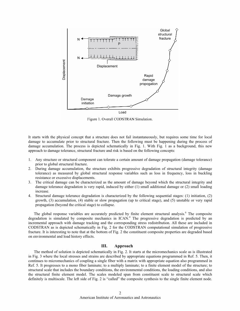
It starts with the physical concept that a structure does not fail instantaneously, but requires some time for local damage to accumulate prior to structural fracture. Then the following must be happening during the process of damage accumulation. The process is depicted schematically in Fig. 1. With Fig. 1 as a background, this new approach to damage tolerance, structural fracture and risk is based on the following concepts: 1. Any structure or structural component can tolerate a certain amount of damage propagation (damage tolerance)
prior to global structural fracture. 2. During damage accumulation, the structure exhibits progressive degradation of structural integrity (damage
tolerance) as measured by global structural response variables such as loss in frequency, loss in buckling resistance or excessive displacements.
3. The critical damage can be characterized as the amount of damage beyond which the structural integrity and damage tolerance degradation is very rapid, induced by either (1) small additional damage or (2) small loading increase.
4. Structural damage tolerance degradation is characterized by the following sequential stages: (1) initiation, (2) growth, (3) accumulation, (4) stable or slow propagation (up to critical stage), and (5) unstable or very rapid propagation (beyond the critical stage) to collapse.
The global response variables are accurately predicted by finite element structural analysis.6 The composite
degradation is simulated by composite mechanics in ICAN.4 The progressive degradation is predicted by an incremental approach with damage tracking and the corresponding stress redistribution. All these are included in CODSTRAN as is depicted schematically in Fig. 2 for the CODSTRAN computational simulation of progressive fracture. It is interesting to note that at the bottom of Fig. 2 the constituent composite properties are degraded based on environmental and load history effects.
III. Approach The method of solution is depicted schematically in Fig. 2. It starts at the micromechanics scale as is illustrated
in Fig. 3 where the local stresses and strains are described by appropriate equations programmed in Ref. 5. Then, it continues to micromechanics of coupling a single fiber with a matrix with appropriate equation also programmed in Ref. 5. It progresses to a mono fiber laminate; to a multiply laminate; to a finite element model of the structure; to structural scale that includes the boundary conditions, the environmental conditions, the loading conditions, and also the structural finite element model. The scales modeled span from constituent scale to structural scale which definitely is multiscale. The left side of Fig. 2 is “called” the composite synthesis to the single finite element node.

American Institute of Aeronautics and Astronautics
3
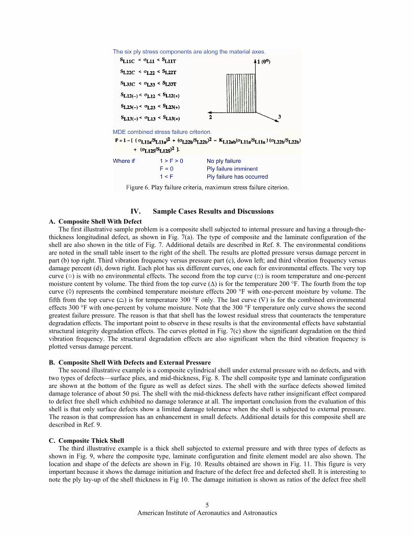
The ICAN code is run for each ply in the laminate and saved so that each finite element node has its own ICAN code run to expedite decomposition. These ICAN runs are saved for the downward composite structural decomposition as noted in the right side of Fig. 2. Once the finite element solution of the first load increment with internal forces/displacements has been obtained at each node then the downward decomposition starts. It is noted that the finite element solution requires nodal information because it is computationally more expedient for the composite decomposition to be performed. Then the decomposition is repeated by using the ply information stored in the synthesis process. The mono ply stresses/strains are then evaluated by using the schematic in Fig. 3 where the local failures are identified. If any failures occurred at this level, the respective stiffness and fractured region are eliminated for the second simulation. The process continues until local incremental convergence has occurred. At this point the load is increased by the second increment. Loading increments are progressively larger at the beginning until local fracture is detected. Then the load increment is reverted back to the last increment and is progressively halved until convergence is achieved and the next load increment is applied by a value equal to the previous load increment. Fig. 4 illustrates this concept. Therefore, the solution is incremental from the micromechanics scale to the structural local/global convergent scale. The structural dynamics equations solved by the finite element in CODSTRAN, which have global variable convergence criteria, are summarized in the chart as is depicted in Fig. 5. These equations are solved at each load increment. There is another level of ply failure criteria. This is a stress failure criterion with a combined stress failure function as depicted in Fig. 6. The combined stress failure criterion is applied first. Then ply dominant stress is identified and that stress is used in the constituents to identify which region has failed. Therefore, the solution is robust and quite reliable as will be illustrated subsequently by the solution results of the sample cases.

American Institute of Aeronautics and Astronautics
4
American Institute of Aeronautics and Astronautics
5
IV. Sample Cases Results and Discussions A. Composite Shell With Defect
The first illustrative sample problem is a composite shell subjected to internal pressure and having a through-the-thickness longitudinal defect, as shown in Fig. 7(a). The type of composite and the laminate configuration of the shell are also shown in the title of Fig. 7. Additional details are described in Ref. 8. The environmental conditions are noted in the small table insert to the right of the shell. The results are plotted pressure versus damage percent in part (b) top right. Third vibration frequency versus pressure part (c), down left; and third vibration frequency versus damage percent (d), down right. Each plot has six different curves, one each for environmental effects. The very top curve (○) is with no environmental effects. The second from the top curve (□) is room temperature and one-percent moisture content by volume. The third from the top curve (∆) is for the temperature 200 °F. The fourth from the top curve (◊) represents the combined temperature moisture effects 200 °F with one-percent moisture by volume. The fifth from the top curve (∩) is for temperature 300 °F only. The last curve (∇) is for the combined environmental effects 300 °F with one-percent by volume moisture. Note that the 300 °F temperature only curve shows the second greatest failure pressure. The reason is that that shell has the lowest residual stress that counteracts the temperature degradation effects. The important point to observe in these results is that the environmental effects have substantial structural integrity degradation effects. The curves plotted in Fig. 7(c) show the significant degradation on the third vibration frequency. The structural degradation effects are also significant when the third vibration frequency is plotted versus damage percent.
B. Composite Shell With Defects and External Pressure The second illustrative example is a composite cylindrical shell under external pressure with no defects, and with
two types of defects—surface plies, and mid-thickness, Fig. 8. The shell composite type and laminate configuration are shown at the bottom of the figure as well as defect sizes. The shell with the surface defects showed limited damage tolerance of about 50 psi. The shell with the mid-thickness defects have rather insignificant effect compared to defect free shell which exhibited no damage tolerance at all. The important conclusion from the evaluation of this shell is that only surface defects show a limited damage tolerance when the shell is subjected to external pressure. The reason is that compression has an enhancement in small defects. Additional details for this composite shell are described in Ref. 9.
C. Composite Thick Shell The third illustrative example is a thick shell subjected to external pressure and with three types of defects as
shown in Fig. 9, where the composite type, laminate configuration and finite element model are also shown. The location and shape of the defects are shown in Fig. 10. Results obtained are shown in Fig. 11. This figure is very important because it shows the damage initiation and fracture of the defect free and defected shell. It is interesting to note the ply lay-up of the shell thickness in Fig 10. The damage initiation is shown as ratios of the defect free shell

American Institute of Aeronautics and Astronautics
6
which is unity (1.0). The damage initiation of the defect free shell is 0.84. This value indicates that the shell has 16 percent damage tolerance from initiation to global fracture. The mid-thickness defects exhibited a 0.75 initiation and 0.77 global fracture. The damage tolerance of the shell with the mid-thickness defects had almost no damage tolerance. That is the shell exhibited a rather brittle behavior. The shell with the inner surface defects had a 0.45 damage initiation and 0.85 global fracture. This shell had the greatest damage tolerance of 40 percent from its initial damage to its global fracture. For additional details see Ref. 10.

American Institute of Aeronautics and Astronautics
7

American Institute of Aeronautics and Astronautics
8
D. Composite Thick Shell Global Degradation The fourth illustrative example is another thick shell under external pressure as shown in Fig. 12 where the shell
composite system, laminate configuration, finite element model are also shown. This shell was analyzed for degradation in the frequency and the buckling load as the damage propagated along the longitudinal direction as shown in Fig. 13. The buckling load did not degrade until the damage length was about 28 in. long. After that the buckling load degradation was relatively great with global collapse of about 80 psi down from 340 or a degradation of about 260 psi. This is a very interesting result because it indicates the buckling of a composite thick shell has a relative large damage tolerance with respect to buckling resistance. Though frequency degradations are not shown here, these degrade slower than the buckling load. Additional details are described in Ref. 11.
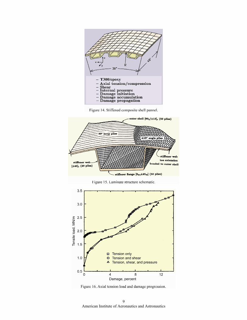
E. Composite Built-Up Structure The fifth illustrative example is for the fracture of a built-up composite structure. The schematic of this structure
is depicted in Fig. 14 where the composite type and a global finite element model are shown of a segment of the composite structure as well as the loading conditions. The composite laminate configuration is shown in Fig. 15 where the finite element model of the internal structure is also shown. The tensile results are summarized in Fig. 16 where the load is plotted against damage percent. Fig. 16 illustrates the load which initiated damage and the load at which global fracture occurred. The points to be observed in Fig. 16 are: (1) the tensile load initial damage starts later and caused maximum damage propagation at fracture; (2) shear with tension exhibited the least damage propagation; and (3) the combination of axial tension with shear and with pressure had the intermediate damage propagation and tensile load to fracture. An important conclusion is that the internal pressure stabilizes fracture and shear load.
American Institute of Aeronautics and Astronautics
9
American Institute of Aeronautics and Astronautics
10
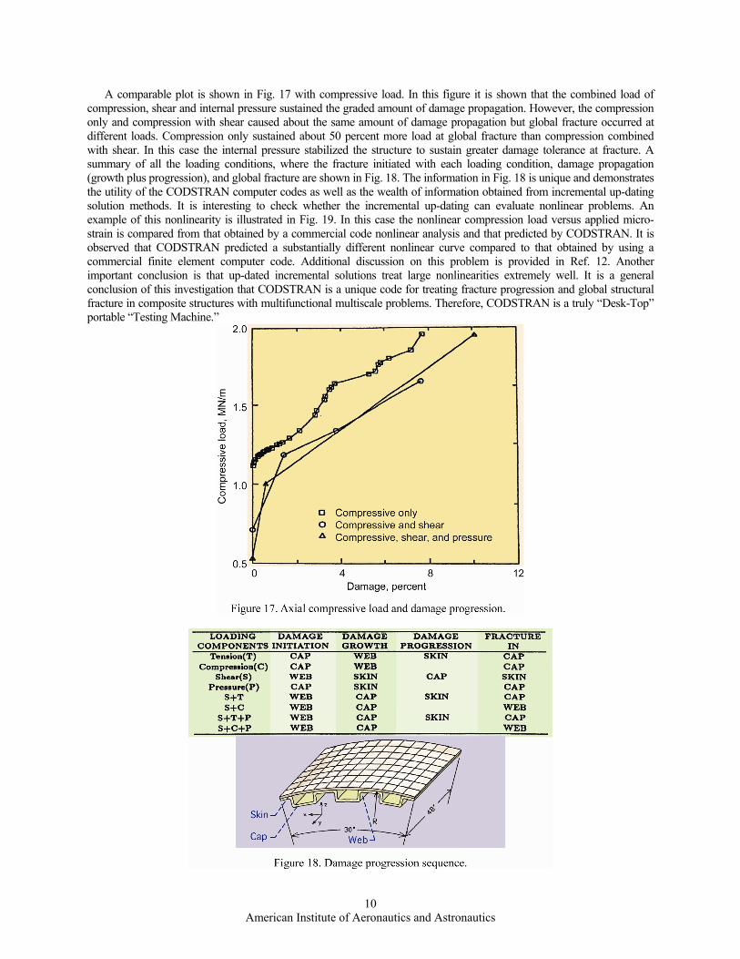
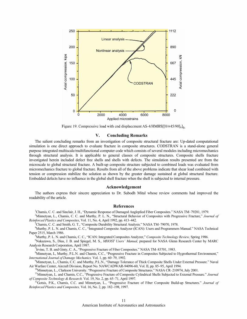
A comparable plot is shown in Fig. 17 with compressive load. In this figure it is shown that the combined load of compression, shear and internal pressure sustained the graded amount of damage propagation. However, the compression only and compression with shear caused about the same amount of damage propagation but global fracture occurred at different loads. Compression only sustained about 50 percent more load at global fracture than compression combined with shear. In this case the internal pressure stabilized the structure to sustain greater damage tolerance at fracture. A summary of all the loading conditions, where the fracture initiated with each loading condition, damage propagation (growth plus progression), and global fracture are shown in Fig. 18. The information in Fig. 18 is unique and demonstrates the utility of the CODSTRAN computer codes as well as the wealth of information obtained from incremental up-dating solution methods. It is interesting to check whether the incremental up-dating can evaluate nonlinear problems. An example of this nonlinearity is illustrated in Fig. 19. In this case the nonlinear compression load versus applied micro-strain is compared from that obtained by a commercial code nonlinear analysis and that predicted by CODSTRAN. It is observed that CODSTRAN predicted a substantially different nonlinear curve compared to that obtained by using a commercial finite element computer code. Additional discussion on this problem is provided in Ref. 12. Another important conclusion is that up-dated incremental solutions treat large nonlinearities extremely well. It is a general conclusion of this investigation that CODSTRAN is a unique code for treating fracture progression and global structural fracture in composite structures with multifunctional multiscale problems. Therefore, CODSTRAN is a truly “Desk-Top” portable “Testing Machine.”
American Institute of Aeronautics and Astronautics
11
.
V. Concluding Remarks The salient concluding remarks from an investigation of composite structural fracture are: Up-dated computational
simulation is one direct approach to evaluate fracture in composite structures. CODSTRAN is a stand-alone general purpose integrated multiscale/multifunctional computer code which consists of several modules including micromechanics through structural analysis. It is applicable to general classes of composite structures. Composite shells fracture investigated herein included defect free shells and shells with defects. The simulation results presented are from the microscale to global structural fracture. A built-up composite structure subjected to combined loads was evaluated from micromechanics fracture to global fracture. Results from all of the above problems indicate that shear load combined with tension or compression stabilize the solution as shown by the greater damage sustained at global structural fracture. Embedded defects have no influence in the global shell fracture when the shell is subjected to internal pressure.
Acknowledgement The authors express their sincere appreciation to Dr. Subodh Mital whose review comments had improved the
readability of the article.
References 1Chamis, C. C. and Sinclair, J. H., “Dynamic Response of Damaged Angleplied Fiber Composites.” NASA TM–79281, 1979. 2Minnetyan, L., Chamis, C. C. and Murthy, P. L. N., “Structural Behavior of Composites with Progressive Fracture,” Journal of Reinforced Plastics and Composites, Vol. 11, No. 4, April 1992, pp. 413–442. 3Chamis, C. C. and Smith, G. T., “Composite Durability Structural Analysis.” NASA TM–79070, 1978. 4Murthy, P. L. N. and Chamis, C. C., “Integrated Composite Analyzer (ICAN): Users and Programmers Manual.” NASA Technical Paper 2515, March 1986. 5Murthy, P. L. N. and Chamis, C. C., “ICAN: Integrated Composites Analyzer,” Composite Technology Review, Spring 1986. 6Nakazawa, S., Dias, J. B. and Spiegel, M. S., MHOST Users’ Manual, prepared for NASA Glenn Research Center by MARC Analysis Research Corporation, April 1987. 7Irvine, T. B. and Ginty, C. A., “Progressive Fracture of Fiber Composites.” NASA TM–83701, 1983. 8Minnetyan, L, Murthy, P.L.N. and Chamis, C.C., “Progressive Fracture in Composites Subjected to Hygrothermal Environment,” International Journal of Damage Mechanics. Vol. 1, pp. 60–79, 1992. 9Minnetyan, L., Chamis, C.C. and Murthy, P.L.N., “Damage Tolerance of Thick Composite Shells Under External Pressure.” Naval Air Warfare Center, Aircraft Division, Report No. NAWCADWAR-94096-60, Vol. II, pp. 85–95, April 1994. 10Minnetyan, L., Clarkson University. “Progressive Fracture of Composite Structures.” NASA CR–210974, July 2001. 11Minnetyan, L. and Chamis, C.C., “Progressive Fracture of Composite Cylindrical Shells Subjected to External Pressure.” Journal of Composite Technology & Research. Vol. 19, No. 2, pp. 65–71, April 1997. 12Gotsis, P.K., Chamis, C.C. and Minnetyan, L., “Progressive Fracture of Fiber Composite Build-up Structures.” Journal of Reinforced Plastics and Composites, Vol. 16, No. 2, pp. 182–198, 1997.