programming the freescale mc908jl16 in c - usc ming...
TRANSCRIPT
Ming Hsieh Department of Electrical Engineering
EE 459Lx - Embedded Systems Design Laboratory
Programming the Freescale MC908JL16 in C
(for CodeWarrior V6.x)
by
Allan G. Weber and Mark Redekopp
1 Introduction
This document discusses the use of the CodeWarrior for Microcontrollers, Special Edition software for pro-gramming the Freescale HC08 microcontrollers in C. Much if this document is generic and applies to anyprocessor in the HC08 family. However parts that discuss things like memory layout are specific to theprocessor currently being used in the class. The class is currently using the MC908JL16 (sometimes listed asMC68HC908JL16.) If the CodeWarrior compiler is used for other HC08 processors the information in theseareas will have to be adjusted to match the other processor.
2 Installation Instructions
The CodeWarrior installation software can be obtained from the instructor if you wish to install the softwareon your own system. It should run on any Windows XP or Windows 7 system. To install the software:
• Copy the installation file to your hard drive. Depending on the version it will have a name like“CW_MCUs_V6_3.exe”.
• Double-click on the file you just copied. There may also be some patch or updates file with it.
• Proceed through the series of questions and agreements posed to you. The program will try to installitself under the Program Files folder of your C drive. Feel free to change that if you desire. When youare asked what type of installation you desire, choose “Complete”.
• If there are any update files these can also be installed.
• After the installation is complete, reboot your system.
The CodeWarrior application can be found in the Start menu under “All Programs”, “Freescale Code-Warrior”, “CW for Microcontrollers V6.x”, “CodeWarrior IDE”. You should now be ready to run the Code-Warrior development system to create software for your microcontroller.
3 Starting a New Project
In order to create a program for your microcontroller, you must first have CodeWarrior create a project. ACodeWarrior project is a folder that contains all the necessary files and configuration information to buildthe project. Start CodeWarrior from the desktop icon or the Start menu and follow these steps.
• File. . . New Project. . . . This will bring up the new project wizard to gather information about yourproject.
EE 459Lx, Rev. 5/29/13 1
• On the Device and Connection screen select the microcontroller you will be using. For most of theclass projects it should be the MC68HC908JL16. Open up the “HC08” list and then open the “JK/JLFamily” list. Click on the microcontroller being used.
In the “Connections” box, select “P&E Multilink/Cyclone Pro” if you will be using the USB program-ming hardware, or “Mon08 Interface” to use the Freescale development boards. See Sec. 9 for moreinformation on the programming hardware. Click “Next”.
• On the Project Parameters screen, select the programming language. C is recommended since it allowsfor larger projects. Selecting C++ limits the program size to only 1KB. Type a project a name in thetext box. CodeWarrior will create a folder of this name under your “My Documents” folder or you canchange the location. Click “Next”.
• On the Add Additional Files screen you can add source files to the project (this can also be done later.)Select the files to add and then click on “Add”. If the “Copy files to project” button is selected thefiles will be copied into the “Sources” folder in the project folder the new project wizard is creating.Use this option if you are going to create your project by modifying one of the demo or template files.If this option is not selected, the source files are left in their original location.
One file in the project must contain the “main()” routine. If the “Create main.c/main.asm file” boxis checked, CodeWarrior will add a main.c file to your project containing this routine. You can lateredit this file to add your own code. Alternatively you can uncheck the main.c box and add your ownfile that contains a main routine. This method is easier if you are copying a main program from someother project. However it is done there must be one, and only one, file that contains a main routine.Click “Next”.
• On the Processor Expert screen, select “None” when it asks about Rapid Application DevelopmentOptions. Click “Next”.
• On the C/C++ Options screen:
– Select “ANSI startup code”.
– For the memory model select “Small”. The small memory model allows access to all of the 512bytes of RAM in the JL16 processor. If you know you only need a few bytes of RAM you can selectthe “Tiny” memory model which restricts access to only 160 bytes. It’s highly recommended thatyou use the “Small” model.
– For floating point, select “None” if your project has no need to do calculations in floating pointarithmetic. If your project requires doing floating point calculations, select one of the choices forthe size of “double” variables, either 32 bits or 64 bits. In either case “float” variables will be32 bits. For more on using floating point see Sec. 5.11.
– Click “Next”;
• On the PC-Lint screen select “No”. Click on “Finish”.
At this point CodeWarrior will create the project folder and bring up the project window.
4 Navigating Through Your Project
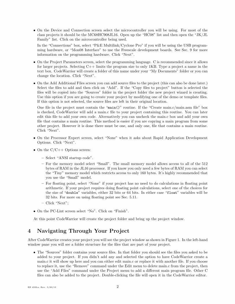
After CodeWarrior creates your project you will see the project window as shown in Figure 1. In the left-handwindow pane you will see a folder structure for the files that are part of your project.
• The “Sources” folder contains your source files. In that folder you should see the files you asked to beadded to your project. If you didn’t add any and selected the option to have CodeWarrior create amain.c it will show up here and you can either edit main.c or replace it with another file. If you chooseto replace it, use the “Remove” command under the Edit menu to delete main.c from the project, thenuse the “Add Files” command under the Project menu to add a different main program file. Other Cfiles can also be added to the project. Double-clicking the file will open it in the CodeWarrior editor.
EE 459Lx, Rev. 5/29/13 2
Figure 1: New C Language Project Structure
• The “Includes” folder contains files specific to model of microcontroller you are using. Your programshould reference the “derivative.h” file which then references the correct include file for your micro-controller. These files declare variable names you can use to read and write the internal registers ofyour microcontroller. It also defines bit names that allow you to read, set, or clear any bit in one ofthe internal registers. You should use these variables rather than trying to create your own system ofaddressing the internal registers.
• The “Libs” Folder contains files to support the specific model of microcontroller being used as well asthe ANSI-C libraries you may use. There should not be any reason to modify the files in this folder.
• The “Startup Code” folder contains code used to allow the processor to run C-language code. Youshould NOT modify this code.
• The “Linker Files” folder, contains files used the CodeWarrior program to compile and link yourprogram. The only file you should be interested in is the “.prm” file that specifies the overall memorymap of your program and also provides the ability to register your interrupt service routines (ISR’s).Initially a new project has a file named “Project.prm” in this folder. As with the main C program file,you can either edit this file or remove it and replace it with another. See Sec. 6 for more information.
5 Writing Code
Writing C code to be run on a microcontroller requires you to manage some of the low-level details of thesystem since a microcontroller has no operating system. Not only are you writing the application to be run onthe system but also the essential portions of OS code. The low-level details you must manage include readingand writing internal registers, writing assembly routines, registering interrupt service routines, dealing withmemory addressing issues, and some basic optimization issues.
EE 459Lx, Rev. 5/29/13 3
More information can be found in the HC08 Manuals included with CodeWarrior, namely the Compilerreference and Linker reference. Copies of these manuals in PDF format can be found on the EE 459Lx website.
5.1 Program Initialization
CodeWarrior automatically includes in a project the necessary start-up code to do things like initialize globalvariables and set up the processor stack.
The HC08 processors have a “Computer Operating Properly” (COP) timer that will cause the processorto execute a reset operation if the COP timer isn’t cleared before it overflows. This is to prevent the chipfrom becoming essentially dead due to a runaway program.
For the programs in EE 459 the COP function isn’t normally needed so the COP timer should be disabled.Put another way, the COP timer MUST be disabled unless your program includes the instructions to resetthe timer periodically. Disabling the COP timer can be done with the instruction below, preferably near thestart of the program.
CONFIG1_COPD = 1; // disable COP reset
5.2 Program Termination
Unlike writing a program on a larger computer, the microcontroller does not have an operating system thatcan take over control once the program is finished and exits. This means the program should never exit. Itshould always be doing something, such as running in an endless loop.
while (1) {
}
If you are not using interrupts, you can also include the assembly language instruction “WAIT” at the endof the program which essentially makes the processor stop and wait for the next interrupt to occur.
5.3 Declaring Variables
In most cases memory can be allocated the same as it would with any C program. However the microcon-trollers have much less memory than is available for C programs on a general purpose computer so it isimportant to make efficient use it. Fixed-point variables, as opposed to floating point variables, should beused whenever possible since they take up less space in memory. The JL16 processor does not have internalfloating point hardware so using floating point can slow down execution speed and increase program size. Ifthe program requires floating point, see Sec. 5.11 for tips on using it.
The native size for operating on data in the microcontroller is 8 bits. Whenever possible variables shouldbe declared as 8-bit values in order to reduce both the amount of RAM memory used and the amount ofcode generated to operate on the variables. Unless a values being stored in a variable are known to exceedthe limits of 8-bits, variables (and functions) should be declared as either “unsigned char” for unsigned 0to 255 values, or “signed char” for -128 to +127 values. Variables can also be declared as type “byte”which is defined as an unsigned char. The table below summarizes the sizes and ranges of the fixed-pointvariables.
Depending on the C compiler the type “char” is sometimes implemented as the same as unsigned char
and sometimes the same as signed char. To avoid confusion, it’s recommended that you always declare thevariable with either the signed or unsigned modifier. The types “int8_t”, “uint8_t”, “int16_t”, etc. thatare defined in some C compilers are not supported in CodeWarrior unless you define these yourself.
Using the smallest variable type necessary is also important for improving execution times in the program.Since the processor can only operate on 8-bit (single byte) quantities, whenever it has to add two or fourbytes quantities this requires multiple instructions. Using a two or four byte variable for something like aloop index can cause the loop to run much slower than expected due to the amount of work that has to bedone each time the index is incremented.
EE 459Lx, Rev. 5/29/13 4
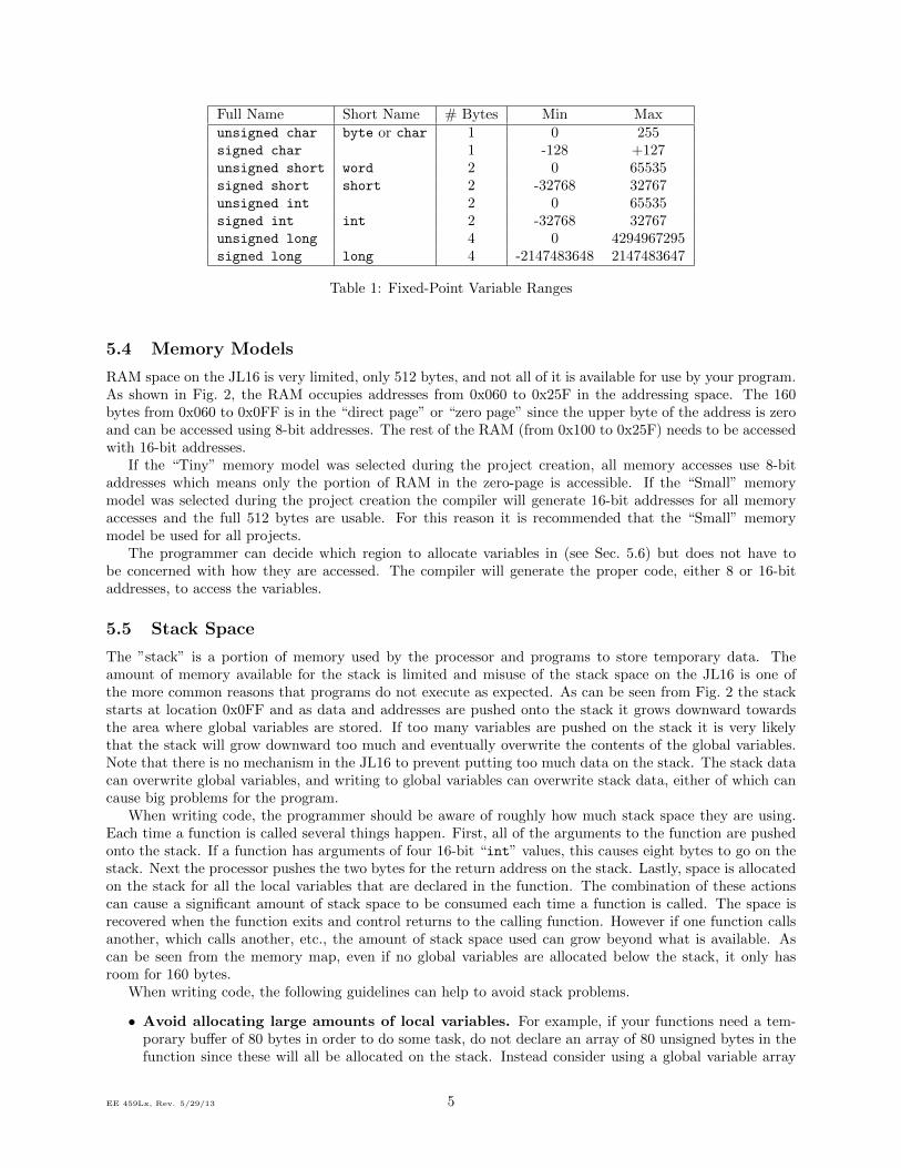
Full Name Short Name # Bytes Min Maxunsigned char byte or char 1 0 255signed char 1 -128 +127unsigned short word 2 0 65535signed short short 2 -32768 32767unsigned int 2 0 65535signed int int 2 -32768 32767unsigned long 4 0 4294967295signed long long 4 -2147483648 2147483647
Table 1: Fixed-Point Variable Ranges
5.4 Memory Models
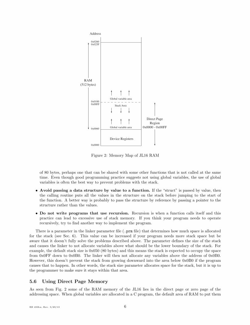
RAM space on the JL16 is very limited, only 512 bytes, and not all of it is available for use by your program.As shown in Fig. 2, the RAM occupies addresses from 0x060 to 0x25F in the addressing space. The 160bytes from 0x060 to 0x0FF is in the “direct page” or “zero page” since the upper byte of the address is zeroand can be accessed using 8-bit addresses. The rest of the RAM (from 0x100 to 0x25F) needs to be accessedwith 16-bit addresses.
If the “Tiny” memory model was selected during the project creation, all memory accesses use 8-bitaddresses which means only the portion of RAM in the zero-page is accessible. If the “Small” memorymodel was selected during the project creation the compiler will generate 16-bit addresses for all memoryaccesses and the full 512 bytes are usable. For this reason it is recommended that the “Small” memorymodel be used for all projects.
The programmer can decide which region to allocate variables in (see Sec. 5.6) but does not have tobe concerned with how they are accessed. The compiler will generate the proper code, either 8 or 16-bitaddresses, to access the variables.
5.5 Stack Space
The ”stack” is a portion of memory used by the processor and programs to store temporary data. Theamount of memory available for the stack is limited and misuse of the stack space on the JL16 is one ofthe more common reasons that programs do not execute as expected. As can be seen from Fig. 2 the stackstarts at location 0x0FF and as data and addresses are pushed onto the stack it grows downward towardsthe area where global variables are stored. If too many variables are pushed on the stack it is very likelythat the stack will grow downward too much and eventually overwrite the contents of the global variables.Note that there is no mechanism in the JL16 to prevent putting too much data on the stack. The stack datacan overwrite global variables, and writing to global variables can overwrite stack data, either of which cancause big problems for the program.
When writing code, the programmer should be aware of roughly how much stack space they are using.Each time a function is called several things happen. First, all of the arguments to the function are pushedonto the stack. If a function has arguments of four 16-bit “int” values, this causes eight bytes to go on thestack. Next the processor pushes the two bytes for the return address on the stack. Lastly, space is allocatedon the stack for all the local variables that are declared in the function. The combination of these actionscan cause a significant amount of stack space to be consumed each time a function is called. The space isrecovered when the function exits and control returns to the calling function. However if one function callsanother, which calls another, etc., the amount of stack space used can grow beyond what is available. Ascan be seen from the memory map, even if no global variables are allocated below the stack, it only hasroom for 160 bytes.
When writing code, the following guidelines can help to avoid stack problems.
• Avoid allocating large amounts of local variables. For example, if your functions need a tem-porary buffer of 80 bytes in order to do some task, do not declare an array of 80 unsigned bytes in thefunction since these will all be allocated on the stack. Instead consider using a global variable array
EE 459Lx, Rev. 5/29/13 5
0x0260
0x0100
0x0060
Device Registers
RAM(512 bytes)
0x0000
Direct PageRegion
0x0000 - 0x00FF
Stack Area
Address
Global variable area
Global variable area
0x025F
0x00FF
Figure 2: Memory Map of JL16 RAM
of 80 bytes, perhaps one that can be shared with some other functions that is not called at the sametime. Even though good programming practice suggests not using global variables, the use of globalvariables is often the best way to prevent problems with the stack.
• Avoid passing a data structure by value to a function. If the “struct” is passed by value, thenthe calling routine puts all the values in the structure on the stack before jumping to the start ofthe function. A better way is probably to pass the structure by reference by passing a pointer to thestructure rather than the values.
• Do not write programs that use recursion. Recursion is when a function calls itself and thispractice can lead to excessive use of stack memory. If you think your program needs to operaterecursively, try to find another way to implement the program.
There is a parameter in the linker parameter file (.prm file) that determines how much space is allocatedfor the stack (see Sec. 6). This value can be increased if your program needs more stack space but beaware that it doesn’t fully solve the problems described above. The parameter defines the size of the stackand causes the linker to not allocate variables above what should be the lower boundary of the stack. Forexample, the default stack size is 0x050 (80 bytes) and this means the stack is expected to occupy the spacefrom 0x0FF down to 0x0B0. The linker will then not allocate any variables above the address of 0x0B0.However, this doesn’t prevent the stack from growing downward into the area below 0x0B0 if the programcauses that to happen. In other words, the stack size parameter allocates space for the stack, but it is up tothe programmer to make sure it stays within that area.
5.6 Using Direct Page Memory
As seen from Fig. 2 some of the RAM memory of the JL16 lies in the direct page or zero page of theaddressing space. When global variables are allocated in a C program, the default area of RAM to put them
EE 459Lx, Rev. 5/29/13 6
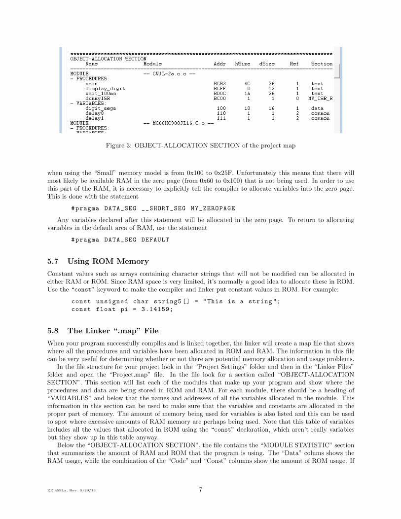
Figure 3: OBJECT-ALLOCATION SECTION of the project map
when using the “Small” memory model is from 0x100 to 0x25F. Unfortunately this means that there willmost likely be available RAM in the zero page (from 0x60 to 0x100) that is not being used. In order to usethis part of the RAM, it is necessary to explicitly tell the compiler to allocate variables into the zero page.This is done with the statement
#pragma DATA_SEG __SHORT_SEG MY_ZEROPAGE
Any variables declared after this statement will be allocated in the zero page. To return to allocatingvariables in the default area of RAM, use the statement
#pragma DATA_SEG DEFAULT
5.7 Using ROM Memory
Constant values such as arrays containing character strings that will not be modified can be allocated ineither RAM or ROM. Since RAM space is very limited, it’s normally a good idea to allocate these in ROM.Use the “const” keyword to make the compiler and linker put constant values in ROM. For example:
const unsigned char string5 [] = "This is a string ";
const float pi = 3.14159;
5.8 The Linker “.map” File
When your program successfully compiles and is linked together, the linker will create a map file that showswhere all the procedures and variables have been allocated in ROM and RAM. The information in this filecan be very useful for determining whether or not there are potential memory allocation and usage problems.
In the file structure for your project look in the “Project Settings” folder and then in the “Linker Files”folder and open the “Project.map” file. In the file look for a section called “OBJECT-ALLOCATIONSECTION”. This section will list each of the modules that make up your program and show where theprocedures and data are being stored in ROM and RAM. For each module, there should be a heading of“VARIABLES” and below that the names and addresses of all the variables allocated in the module. Thisinformation in this section can be used to make sure that the variables and constants are allocated in theproper part of memory. The amount of memory being used for variables is also listed and this can be usedto spot where excessive amounts of RAM memory are perhaps being used. Note that this table of variablesincludes all the values that allocated in ROM using the “const” declaration, which aren’t really variablesbut they show up in this table anyway.
Below the “OBJECT-ALLOCATION SECTION”, the file contains the “MODULE STATISTIC” sectionthat summarizes the amount of RAM and ROM that the program is using. The “Data” colums shows theRAM usage, while the combination of the “Code” and “Const” columns show the amount of ROM usage. If
EE 459Lx, Rev. 5/29/13 7
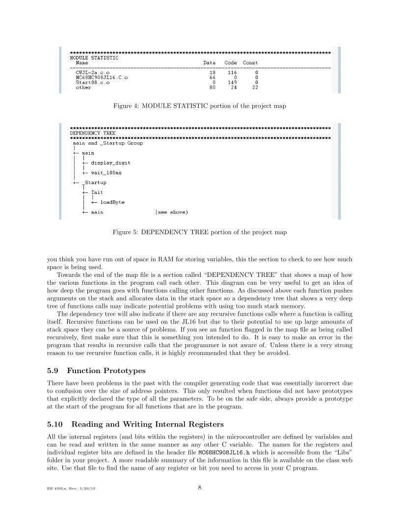
Figure 4: MODULE STATISTIC portion of the project map
Figure 5: DEPENDENCY TREE portion of the project map
you think you have run out of space in RAM for storing variables, this the section to check to see how muchspace is being used.
Towards the end of the map file is a section called “DEPENDENCY TREE” that shows a map of howthe various functions in the program call each other. This diagram can be very useful to get an idea ofhow deep the program goes with functions calling other functions. As discussed above each function pushesarguments on the stack and allocates data in the stack space so a dependency tree that shows a very deeptree of functions calls may indicate potential problems with using too much stack memory.
The dependency tree will also indicate if there are any recursive functions calls where a function is callingitself. Recursive functions can be used on the JL16 but due to their potential to use up large amounts ofstack space they can be a source of problems. If you see an function flagged in the map file as being calledrecursively, first make sure that this is something you intended to do. It is easy to make an error in theprogram that results in recursive calls that the programmer is not aware of. Unless there is a very strongreason to use recursive function calls, it is highly recommended that they be avoided.
5.9 Function Prototypes
There have been problems in the past with the compiler generating code that was essentially incorrect dueto confusion over the size of address pointers. This only resulted when functions did not have prototypesthat explicitly declared the type of all the parameters. To be on the safe side, always provide a prototypeat the start of the program for all functions that are in the program.
5.10 Reading and Writing Internal Registers
All the internal registers (and bits within the registers) in the microcontroller are defined by variables andcan be read and written in the same manner as any other C variable. The names for the registers andindividual register bits are defined in the header file MC68HC908JL16.h which is accessible from the “Libs”folder in your project. A more readable summary of the information in this file is available on the class website. Use that file to find the name of any register or bit you need to access in your C program.
EE 459Lx, Rev. 5/29/13 8

Register Name Hexadecimal AddressPTA 0x0000PTB 0x0001PTD 0x0003DDRA 0x0004DDRB 0x0005DDRD 0x0007
Table 2: I/O Register Names and Addresses
For example, ports A, B, and D are defined by variables named PTA, PTB, and PTD. You may performoperations on these variables just as you would any other.
PTA = 0xf4;
PTD = 5 * PTB + 2;
unsigned char my_var = PTA;
PTB += 1;
Individual bits in the registers can be accessed using the names defined for each bit. For example, the namePTA_PTA0 will access the LSB of Port A.
PTB_PTB4 = 1;
if (PTD_PTD2 == 0) { ... }
Alternatively, you can use bitwise operations such as AND and OR.
bit0 = PTA & 0x01;
bit3 = PTA & 0x08;
When writing individual bits in the registers it is important to be aware that this will cause the micro-controller to first read the full eight-bit byte, modify the byte, and then write the full byte back. Some ofthe internal functions of the microcontroller are affected by reading a register so it is important to be awareof any potential side effects when accessing the registers.
5.10.1 Defining Groups of Register Bits
In some applications groups of bits in the I/O registers are part of a multi-bit quantity and it is preferableto refer to all the bits together rather than individually. Groups of bits can be defined as a single quantityand operations can be performed on them as a group. For example, let’s assume we want to refer to portB, bits 1, 2 and 3 as a three bit quantity (VidMode), and to also refer to bits 6 and 7 as a two bit quantity(RAMSel). The following code defines these groups of bits.
volatile struct {
unsigned char :1; /* bit 0 (LSB) - no name assigned */
unsigned char VidMode :3; /* bits 1-3 = VidMode */
unsigned char :2; /* bits 4-5 - no name assigned */
unsigned char RAMSel :2; /* bits 6-7 (MSB) = RAMSel */
} MyPTB @0x0001; /* 0x0001 = address of PTB */
#define VidMode MyPTB.VidMode
#define RAMSel MyPTB.RAMSel
The last line of the struct declaration above assigns the data structure to the numerical address of theregister, in this case 0x0001 for PTB. A list of addresses for the more commonly used registers is shown inTable 2. A complete list of all register addresses is in the microcontroller manual.
Once these names are defined the groups of register bits can be accessed in the program as single numericalquantities. For example
EE 459Lx, Rev. 5/29/13 9
if (RAMSel == 2) {
VidMode = 6;
}
Bits are assigned in the “struct” in the order LSB (bit 0) to MSB (bit 7.) It is necessary to list all eightbits in the data structure but a name does not have be assigned to all the bits, just the ones where you wantto group them together, or to refer to it by some name other than the one defined by the system.
The multi-bit quantities are oriented the same as the full register as far as the least significant and mostsignificant bits. In the example above, bit 3 is the MSB and bit 1 is the LSB of the VidMode group of threebits. The instruction “Vidmode = 6” will result in a one stored in PTB3 and PTB2, and a zero stored inPTB1. This is important to remember when deciding how to assign functions to the different bits.
Bits can still be referred to in the program with the names defined for them by the standard header files.For example, if we use the definition above, then the following lines of code
PTB_PTB6 = 1;
PTB_PTB7 = 1;
do the same thing as
RAMSel = 3;
5.11 Floating Point
The CodeWarrior compiler can generate code that does floating point calculations. This allows programs tobe written in a style very similar to how it would be written for a larger computer. However programmersshould keep in mind that the JL16 processor does not contain any floating point arithmetic hardware soall floating point calculations are implemented by doing multiple 8-bit integer arithmetic operations. Theresulting code can be relatively slow to execute. Programs should not use floating point unless there arecompelling reasons to do so. Whenever possible, integer arithmetic should be used instead.
When floating point arithmetic is used, CodeWarrior will add library routines that do the floating pointoperations to the final binary program. This can dramatically increase the size of the program. For example,a program that does a few floating point multiplies, adds and square root operations will cause the executablecode to be about 4KB larger than without the floating point operations. This can be a problem if the programis close to filling out all the ROM space in the processor.
If using floating point, do not use 64-bit “double” variables unless absolutely necessary since doing 64-bitoperations requires a larger number of 8-bit operations that must be done for each floating point operations.
5.12 Standard C Library
CodeWarrior includes a standard C library that contains many of the routines that programmers are usedto having available to use in their programs. Routines like “sprintf” and “sscanf” can be used the sameway as on larger systems. Routines that would do I/O operations are not usable since the system does nothave a file system or other I/O capability.
The CodeWarrior linker will include any needed routines from the standard C library in the binary outputwhen the program is compiled and linked. Programmers must keep in mind that these can significantlyincrease the size of their final executable program. For example, using “sprintf” in a program to createformatted strings of characters will cause about 3.5KB of extra code to be included in the final executableprogram.
5.13 Including Assembly Language Code in C
You can write assembly instructions and call assembly language routines from within your C code by usingthe “asm{ }” construct. Below are some guidelines for writing assembly code.
• Within the brackets you may write one assembly instruction per line.
• Labels must be defined on their own line.
EE 459Lx, Rev. 5/29/13 10
• The “;” is used for comments.
• Global variables can be accessed using their name.
• Local variables in a function are stored as part of the stack frame and must be accessed using the stackpointer.
• Upon completing your assembly code. You must ensure that the stack is returned to its original stateit was before starting your assembly code. What that means is that if you add variables to the stackor call another routine from your assembly code you must be sure to pop the stack or use the RTSinstruction as appropriate.
See the program samples on the class web site for some examples of using assembly code in C programs.For more information on this see the HC08 Compiler Manual, page 543.
5.14 Using Interrupts
If your program uses interrupts, either external one from the IRQ input or internal ones from the timer,ADC, etc., then you need to include the following at some point in the program to clear the processor’sinterrupt mask
EnableInterrupts;
This command is sufficient to allow the IRQ input to cause an interrupt. However this is not enough toenable interrupts for any of the modules. Each module has its own interrupt enable bit in the register forthe module and this bit must be set to the enable state for the module to generate an interrupt.
Any interrupt that is enabled must have a corresponding interrupt service routine (ISR) to handle theinterrupt. The ISRs are written just like any other C function but ISRs must generate code that returns fromthe routine with an RTI (Return From Interrupt) instruction rather than an RTS (Return From Subroutine)instruction. The compiler will generate the proper return instruction if told that the routine is an ISR. Thiscan be done in a couple of ways. The keyword “interrupt” can be used in the routine declaration, as isshown below.
void interrupt myISR(void)
{
// ISR code
}
Another way is to use a #pragma keyword to tell the compiler it is an ISR.
#pragma TRAP_PROC
void myISR(void)
{
// ISR code
}
After you have written your ISR, you must enter its address into microcontroller’s interrupt vector table.The vector table runs from address 0xFFDE up to 0xFFFE. See the table on page 25 of the MC908JL16manual for a list of vectors. You can register your ISR in the vector table in the PRM file of your project.Use the command
VECTOR ADDRESS 0xADDR myISR
where “ADDR” is the address of the interrupt vector you are using. For example the following registers“myTimerISR” as the ISR for the TIM1 overflow interrupt.
VECTOR ADDRESS 0xFFF2 myTimerISR
You may also use the vector number rather than specifying the vector address.
VECTOR 5 myTimerISR
This will register the routine named myTimerISR to the vector table entry 5.
EE 459Lx, Rev. 5/29/13 11
5.15 Code Optimization
A good reference on optimizing C programs for the HC08 processors is Freescale’s application note AN2093which is available on the class web site. The information below summarizes much of what is contained inthat document.
As stated above, always use the smallest variable possible. Don’t use a 16-bit “int” if a 8-bit “char” or“byte” will work. The processor does all arithmetic operations eight bits at a time so using a 16-bit valuecan more than double the amount of work needed to do calculations.
When implementing loops, if possible make the loop index count down to zero rather than counting upto some number. The processor is more efficient at checking for a zero value than doing compares againsta non-zero value. If a loop is always going to be performed the same small number of times, consider“unrolling” the loop and simply repeating the instructions the required number of times.
Make use of the direct page RAM location when storing values that will be accessed often. Someinstructions only work with direct page addresses and in general access time to direct page locations issignificantly faster than for those requiring a 16-bit address.
Do not use complex data structures. Referencing elements of a data structure often require doing multi-plications to find the proper element and this can be very slow on an 8-bit processor. It’s better to insteaduse multiple one-dimensional arrays of a simple data type.
Different #pragma statements can be used to tell the compiler how to handle translation of certainfunctions. A list of these pragmas can be found starting at page 355 of the Compiler Manual.
6 The PRM File
The PRM file controls where procedures and data are put in memory. It defines “SEGMENTS” whichidentify portions of memory and your code and variables can be placed in those segments. One or more codesegments and data segments are defined to cover the areas supported by the microcontroller (0x60-0x25F fordata and 0xBC00 - 0xFBFF for code). The example below from a PRM file defines two areas for variables(Z RAM and RAM) and one for code (ROM). The “Z RAM” segment covers the range 0x60 to 0xff wheredata can be accessed using only an 8-bit address. The remainder of the RAM area (0x100 to 0x25f) iscovered by the “RAM” segment. The ROM segment starts at 0xBC00 and all the program code is storedthere.
/* Here all RAM/ROM areas are listed. Used in PLACEMENT below. */
SEGMENTS
Z_RAM = READ_WRITE 0x0060 TO 0x00FF;
RAM = READ_WRITE 0x0100 TO 0x025F;
ROM = READ_ONLY 0xBC00 TO 0xFBFF;
END
/* Here all predefined and users segments are placed
into the SEGMENTS defined above. */
PLACEMENT
DEFAULT_RAM , INTO RAM /* non -zero page variables */
PRESTART , /* startup code */
STARTUP , /* startup data structures */
STRINGS , /* string literals */
DEFAULT_ROM INTO ROM;
_DATA_ZEROPAGE ,
MY_ZEROPAGE INTO Z_RAM; /* zero page variables */
END
The “PLACEMENT” section of the PRM file defines the names are associated with each segment. Inyour C code you can use the “#pragma” statements to indicate which segment code should be placed into(see the examples). It is probably a good idea just to use the example as a template for your PRM file and
EE 459Lx, Rev. 5/29/13 12
your allocation of code. More information on using #pragma statements for memory allocation can be foundon page 536 of the Compiler Manual. Information for the PRM file can be found in the Linker Manual.
The size of the processor stack can be adjusted using the “STACKSIZE” command. For example,
STACKSIZE 0x60
sets the stack size to 96 bytes. As discussed in Sec. 5.5, this only sets the amount of space allocated for thestack, it doesn’t actively limit the stack to staying within this region.
7 Building your Application
You can compile and link your project by using the “Make” command under the “Project” menu. This willcompile any source files that have changed since the last time the project was built, and then link it together.Whenever you successfully “make” your application, a file called “Project.abs.s19” will be generated in yourproject directory in the “bin” subfolder. This file contains the binary data that must be programmed intothe microcontroller.
8 Sample Programs
On the computers in the EE 459 lab, in the “JL16 Samples” folder in the EE 459 account are the followingfiles that may be of interest to those writing C programs. These programs are also available on the EE 459library web site.
jl16.c This is a template file with the required declaration and initialization code but nothing else. It canbe used as a starting point for writing a program in C.
jl16-0.c A very simple program for showing the micro is working. It loops forever turning bit zero in portA (PTA0) on and off as rapidly as possible.
jl16-1.c This program reads a switch input and turns an LED on and off.
jl16-2a.c This program counts up and down on a seven-segment display. The program uses nested loops toimplement the counter delay.
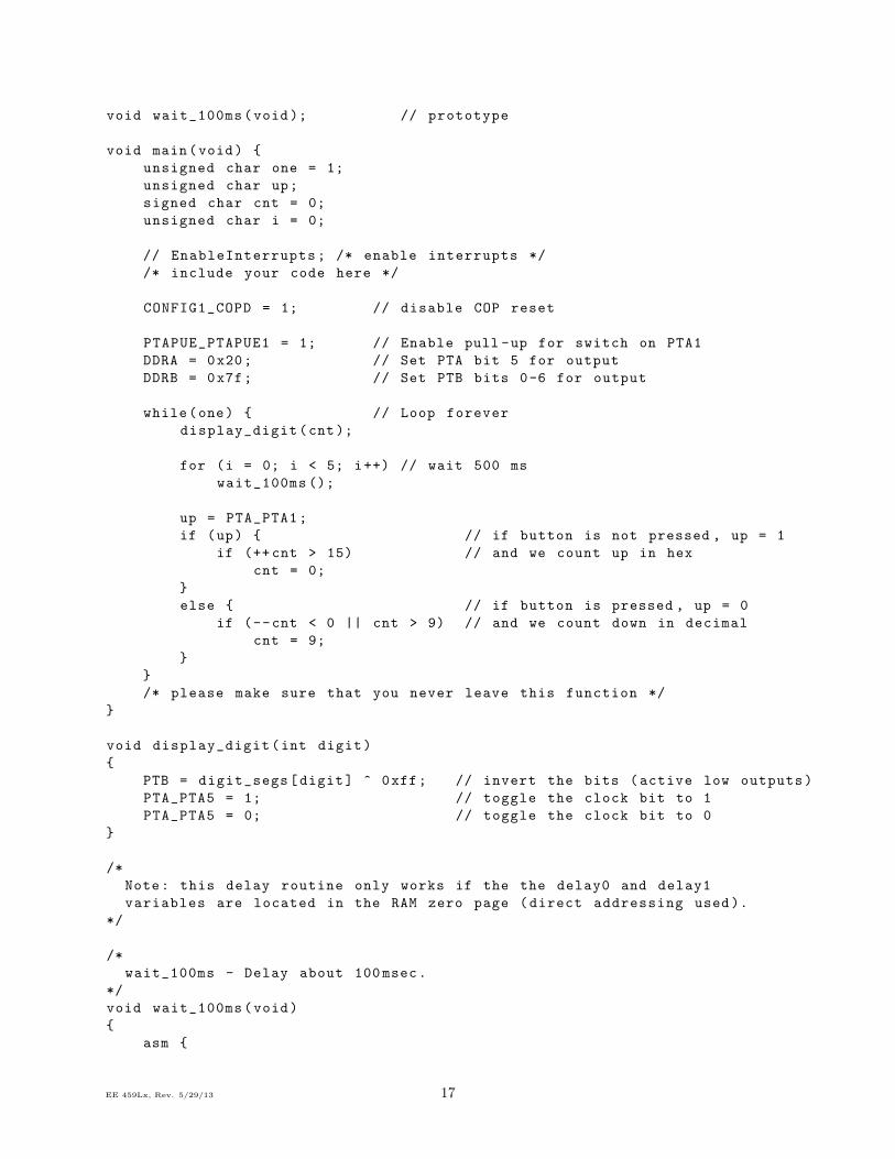
jl16-2b.c Similar to jl16-2a.c but shows how to allocate variables into the zero-page of RAM for moreefficient access. See Appendix A for a listing.
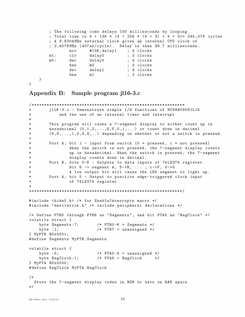
jl16-3.c Similar to jl16-2a.c but uses an internal timer and interrupts to implement the delay. Use linkerparameter file jl16-3.prm for this sample program. See Appendix B for a listing.
jl16-4.c Demonstrates interfacing to an LCD display using an 8-bit interface. Puts up a short message onthe display.
jl16-5.c Similar to jl16-4.c but uses a 4-bit interface to the LCD
jl16-6.c This program demonstrates using an RS-232 serial interface to control an LCD display.
jl16-7.c Examples of reading and writing data to an EEPROM using an I2C bus.
jl16-8.c Shows how to stores and retrieves data in the JL16 FLASH memory under program control.
EE 459Lx, Rev. 5/29/13 13
9 Programming the JL16 from CodeWarrior
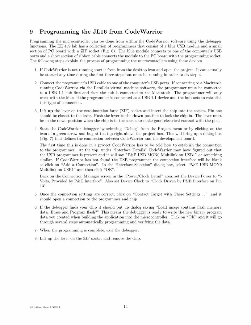
Programming the microcontroller can be done from within the CodeWarrior software using the debuggerfunctions. The EE 459 lab has a collection of programmers that consist of a blue USB module and a smallsection of PC board with a ZIF socket (Fig. 6). The blue module connects to one of the computer’s USBports and a short section of ribbon cable connects the module to the PC board with the programming socket.The following steps explain the process of programming the microcontrollers using these devices.
1. If CodeWarrior is not running start it from from the desktop icon and open the project. It can actuallybe started any time during the first three steps but must be running in order to do step 4.
2. Connect the programmer’s USB cable to one of the computer’s USB ports. If connecting to a Macintoshrunning CodeWarrior via the Parallels virtual machine software, the programmer must be connectedto a USB 1.1 hub first and then the hub is connected to the Macintosh. The programmer will onlywork with the Macs if the programmer is connected as a USB 1.1 device and the hub acts to establishthis type of connection.
3. Lift up the lever on the zero-insertion force (ZIF) socket and insert the chip into the socket. Pin oneshould be closest to the lever. Push the lever to the down position to lock the chip in. The lever mustbe in the down position when the chip is in the socket to make good electrical contact with the pins.
4. Start the CodeWarrior debugger by selecting “Debug” from the Project menu or by clicking on theicon of a green arrow and bug at the top right above the project box. This will bring up a dialog box(Fig. 7) that defines the connection between CodeWarrior and the development board.
The first time this is done in a project CodeWarrior has to be told how to establish the connectionto the programmer. At the top, under “Interface Details” CodeWarrior may have figured out thatthe USB programmer is present and it will say ”P&E USB MON0 Multilink on USB1” or somethingsimilar. If CodeWarrior has not found the USB programmer the connection interface will be blankso click on “Add a Connection”. In the “Interface Selection” dialog box, select “P&E USB MON0Multilink on USB1” and then click “OK”.
Back on the Connection Manager screen in the “Power/Clock Detail” area, set the Device Power to “5Volts, Provided by P&E Interface”. Also set Device Clock to “Clock Driven by P&E Interface on Pin13”.
5. Once the connection settings are correct, click on “Contact Target with These Settings. . . ” and itshould open a connection to the programmer and chip.
6. If the debugger finds your chip it should put up dialog saying “Load image contains flash memorydata. Erase and Program flash?” This means the debugger is ready to write the new binary programdata you created when building the application into the microcontroller. Click on “OK” and it will gothrough several steps automatically programming and verifying the data.
7. When the programming is complete, exit the debugger.
8. Lift up the lever on the ZIF socket and remove the chip.
EE 459Lx, Rev. 5/29/13 14
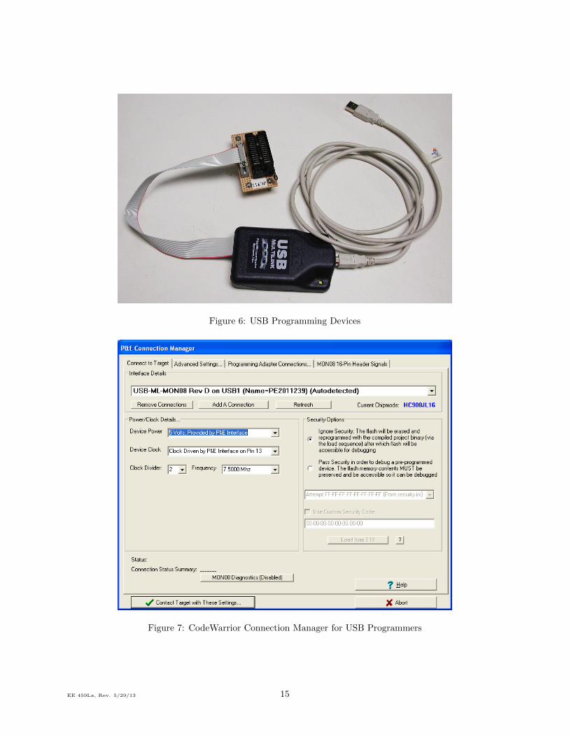
Figure 6: USB Programming Devices
Figure 7: CodeWarrior Connection Manager for USB Programmers
EE 459Lx, Rev. 5/29/13 15
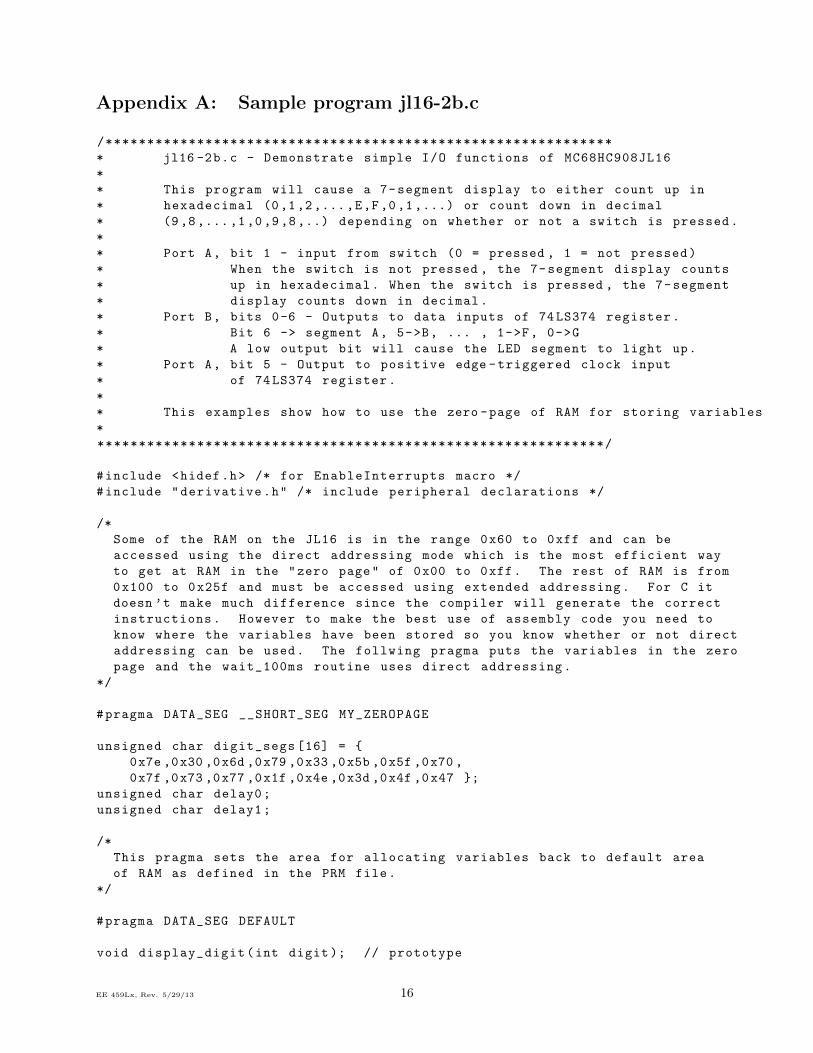
Appendix A: Sample program jl16-2b.c
/*************************************************************
* jl16 -2b.c - Demonstrate simple I/O functions of MC68HC908JL16
*
* This program will cause a 7-segment display to either count up in
* hexadecimal (0,1,2,...,E,F,0 ,1 ,...) or count down in decimal
* (9,8,...,1,0,9,8,..) depending on whether or not a switch is pressed.
*
* Port A, bit 1 - input from switch (0 = pressed , 1 = not pressed)
* When the switch is not pressed , the 7-segment display counts
* up in hexadecimal. When the switch is pressed , the 7-segment
* display counts down in decimal.
* Port B, bits 0-6 - Outputs to data inputs of 74LS374 register.
* Bit 6 -> segment A, 5->B, ... , 1->F, 0->G
* A low output bit will cause the LED segment to light up.
* Port A, bit 5 - Output to positive edge -triggered clock input
* of 74LS374 register.
*
* This examples show how to use the zero -page of RAM for storing variables
*
*************************************************************/
#include <hidef.h> /* for EnableInterrupts macro */
#include "derivative.h" /* include peripheral declarations */
/*
Some of the RAM on the JL16 is in the range 0x60 to 0xff and can be
accessed using the direct addressing mode which is the most efficient way
to get at RAM in the "zero page" of 0x00 to 0xff. The rest of RAM is from
0x100 to 0x25f and must be accessed using extended addressing. For C it
doesn ’t make much difference since the compiler will generate the correct
instructions. However to make the best use of assembly code you need to
know where the variables have been stored so you know whether or not direct
addressing can be used. The follwing pragma puts the variables in the zero
page and the wait_100ms routine uses direct addressing.
*/
#pragma DATA_SEG __SHORT_SEG MY_ZEROPAGE
unsigned char digit_segs [16] = {
0x7e ,0x30 ,0x6d ,0x79 ,0x33 ,0x5b ,0x5f ,0x70 ,
0x7f ,0x73 ,0x77 ,0x1f ,0x4e ,0x3d ,0x4f ,0x47 };
unsigned char delay0;
unsigned char delay1;
/*
This pragma sets the area for allocating variables back to default area
of RAM as defined in the PRM file.
*/
#pragma DATA_SEG DEFAULT
void display_digit(int digit); // prototype
EE 459Lx, Rev. 5/29/13 16
void wait_100ms(void); // prototype
void main(void) {
unsigned char one = 1;
unsigned char up;
signed char cnt = 0;
unsigned char i = 0;
// EnableInterrupts; /* enable interrupts */
/* include your code here */
CONFIG1_COPD = 1; // disable COP reset
PTAPUE_PTAPUE1 = 1; // Enable pull -up for switch on PTA1
DDRA = 0x20; // Set PTA bit 5 for output
DDRB = 0x7f; // Set PTB bits 0-6 for output
while(one) { // Loop forever
display_digit(cnt);
for (i = 0; i < 5; i++) // wait 500 ms
wait_100ms ();
up = PTA_PTA1;
if (up) { // if button is not pressed , up = 1
if (++ cnt > 15) // and we count up in hex
cnt = 0;
}
else { // if button is pressed , up = 0
if (--cnt < 0 || cnt > 9) // and we count down in decimal
cnt = 9;
}
}
/* please make sure that you never leave this function */
}
void display_digit(int digit)
{
PTB = digit_segs[digit] ^ 0xff; // invert the bits (active low outputs)
PTA_PTA5 = 1; // toggle the clock bit to 1
PTA_PTA5 = 0; // toggle the clock bit to 0
}
/*
Note: this delay routine only works if the the delay0 and delay1
variables are located in the RAM zero page (direct addressing used).
*/
/*
wait_100ms - Delay about 100 msec.
*/
void wait_100ms(void)
{
asm {
EE 459Lx, Rev. 5/29/13 17
; The following code delays 100 milliseconds by looping.
; Total time is 4 + 136 * (3 + 256 * (4 + 3) + 4 + 3)= 245 ,076 cycles
; A 9.8304 MHz external clock gives an internal CPU clock of
; 2.4576 MHz (407ns/cycle ). Delay is then 99.7 milliseconds.
mov #136, delay1 ; 4 clocks
m1: clr delay0 ; 3 clocks
m0: dec delay0 ; 4 clocks
bne m0 ; 3 clocks
dec delay1 ; 4 clocks
bne m1 ; 3 clocks
}
}
Appendix B: Sample program jl16-3.c
/*************************************************************
* jl16 -3.c - Demonstrate simple I/O functions of MC68HC908JL16
* and the use of an internal timer and interrupt
*
* This program will cause a 7-segment display to either count up in
* hexadecimal (0,1,2,...,E,F,0 ,1 ,...) or count down in decimal
* (9,8,...,1,0,9,8,..) depending on whether or not a switch is pressed.
*
* Port A, bit 1 - input from switch (0 = pressed , 1 = not pressed)
* When the switch is not pressed , the 7-segment display counts
* up in hexadecimal. When the switch is pressed , the 7-segment
* display counts down in decimal.
* Port B, bits 0-6 - Outputs to data inputs of 74LS374 register.
* Bit 6 -> segment A, 5->B, ... , 1->F, 0->G
* A low output bit will cause the LED segment to light up.
* Port A, bit 5 - Output to positive edge -triggered clock input
* of 74LS374 register.
*
*************************************************************/
#include <hidef.h> /* for EnableInterrupts macro */
#include "derivative.h" /* include peripheral declarations */
/* Define PTB0 through PTB6 as "Segments", and bit PTA5 as "RegClock" */
volatile struct {
byte Segments :7; /* PTB0 -6 = Segments */
byte :1; /* PTB7 = unassigned */
} MyPTB @0x0001;
#define Segments MyPTB.Segments
volatile struct {
byte :5; /* PTA0 -4 = unassigned */
byte RegClock :1; /* PTA5 = RegClock */
} MyPTA @0x0000;
#define RegClock MyPTA.RegClock
/*
Store the 7-segment display codes in ROM to save on RAM space
*/
EE 459Lx, Rev. 5/29/13 18
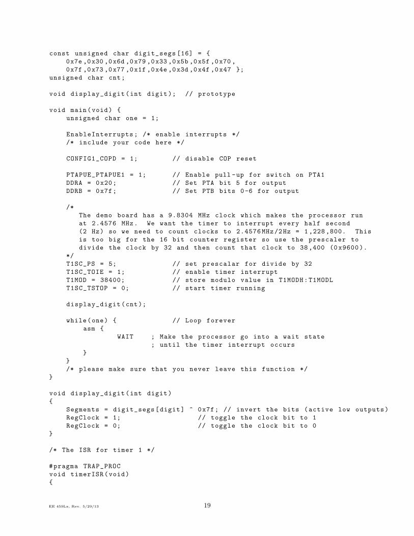
const unsigned char digit_segs [16] = {
0x7e ,0x30 ,0x6d ,0x79 ,0x33 ,0x5b ,0x5f ,0x70 ,
0x7f ,0x73 ,0x77 ,0x1f ,0x4e ,0x3d ,0x4f ,0x47 };
unsigned char cnt;
void display_digit(int digit); // prototype
void main(void) {
unsigned char one = 1;
EnableInterrupts; /* enable interrupts */
/* include your code here */
CONFIG1_COPD = 1; // disable COP reset
PTAPUE_PTAPUE1 = 1; // Enable pull -up for switch on PTA1
DDRA = 0x20; // Set PTA bit 5 for output
DDRB = 0x7f; // Set PTB bits 0-6 for output
/*
The demo board has a 9.8304 MHz clock which makes the processor run
at 2.4576 MHz. We want the timer to interrupt every half second
(2 Hz) so we need to count clocks to 2.4576 MHz/2Hz = 1 ,228 ,800. This
is too big for the 16 bit counter register so use the prescaler to
divide the clock by 32 and then count that clock to 38,400 (0 x9600).
*/
T1SC_PS = 5; // set prescalar for divide by 32
T1SC_TOIE = 1; // enable timer interrupt
T1MOD = 38400; // store modulo value in T1MODH:T1MODL
T1SC_TSTOP = 0; // start timer running
display_digit(cnt);
while(one) { // Loop forever
asm {
WAIT ; Make the processor go into a wait state
; until the timer interrupt occurs
}
}
/* please make sure that you never leave this function */
}
void display_digit(int digit)
{
Segments = digit_segs[digit] ^ 0x7f; // invert the bits (active low outputs)
RegClock = 1; // toggle the clock bit to 1
RegClock = 0; // toggle the clock bit to 0
}
/* The ISR for timer 1 */
#pragma TRAP_PROC
void timerISR(void)
{
EE 459Lx, Rev. 5/29/13 19
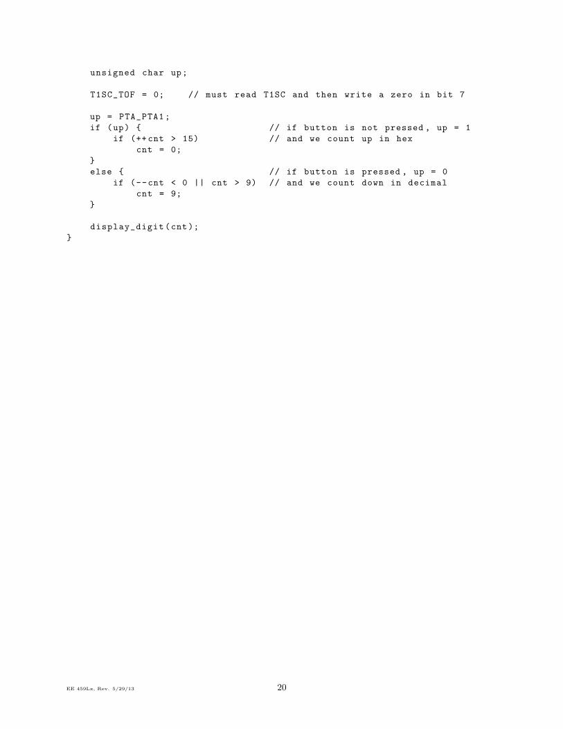
unsigned char up;
T1SC_TOF = 0; // must read T1SC and then write a zero in bit 7
up = PTA_PTA1;
if (up) { // if button is not pressed , up = 1
if (++ cnt > 15) // and we count up in hex
cnt = 0;
}
else { // if button is pressed , up = 0
if (--cnt < 0 || cnt > 9) // and we count down in decimal
cnt = 9;
}
display_digit(cnt);
}
EE 459Lx, Rev. 5/29/13 20