programming guide nuscan 2400 / 4100 - adesso · 5 1.3.2 scan engine interface without decoding...
TRANSCRIPT

Programming Guide Nuscan 2400 / 4100
Table of Contents
About this manual .................................................................................. I
Introduction .......................................................................................... I
Caution ................................................................................................. I
Service information ............................................................................... I
Manual apply to the following models .................................................. I
Revised version ..................................................................................... I
1. Product Specifications ....................................................................... 1
1.1 Technical parameters ...................................................................... 1
1.2 Barcode default parameters ............................................................ 2
1.3 Interface specifications ................................................................... 3
1.3.1 Scan module interface CMOS ....................................................................4
1.3.2 Scan engine interface without decoding .....................................................5
1.3.3 Standard serial port (DB9) .........................................................................6
1.3.4 RS485 interface .........................................................................................7
1.3.5 USB interface ............................................................................................8
1.3.6 PS2 Keyboard wedge .................................................................................9
2. Command instructions .................................................................... 10
2.1 Barcode command instructions .................................................... 10
2.2 Serial port command instructions ................................................. 11
2.3 Command table ............................................................................ 12
2.4 Quick command (HEX format) .................................................... 13
3. General command data format ....................................................... 14
3.1 SET & END ................................................................................. 14
3.2 Defaults parameter ....................................................................... 15
3.3 TRIGGER_SCAN & STOP_SCAN ............................................. 16
3.4 Version ......................................................................................... 17
3.5 OPEN_BEEPER .......................................................................... 18
3.6 ACK Handshaking ....................................................................... 20
4. Modify parameters command ......................................................... 21
4.1 Data output mode ......................................................................... 21
4.2 Keyboard language ...................................................................... 22
4.3 Buzzer & LED control ................................................................. 23
4.4 Serial port setting ......................................................................... 24
4.5 Serial port respond ....................................................................... 26
4.6 Transmit “No Read” Message ...................................................... 27
4.7 Power mode ................................................................................. 28
4.8 Trigger mode & read mode .......................................................... 29
4.9 Delay for repeating to read the same barcode ............................... 30
4.10 Light delay after triggering the scanner caused by the trigger pin .............................................................................................................. 31
4.11 Light delay after triggering the scanner caused by the serial port commands/auto trigger........................................................................... 32
4.12 Laser mode & Swing plate boot mode ........................................ 33
4.13 Auto trigger ................................................................................ 34
4.14 Barcode setting........................................................................... 35
4.14.1 EAN13 & UPC-A .................................................................................. 36
4.14.2 EAN8..................................................................................................... 37
4.14.3 UPC-E ................................................................................................... 38
4.14.4 CODABAR (NW-7) ............................................................................... 39
4.14.5 CODE 39 ............................................................................................... 41
4.14.6 CODE 93 ............................................................................................... 44
4.14.7 INTERLEAVED 2 OF 5......................................................................... 46
4.14.8 STANDARD 2 of 5 (Industrial 2 of 5) .................................................... 48
4.14.9 MATRIX 2 of 5 ...................................................................................... 50
4.14.10 CODE 128 & EAN/UCC 128 ............................................................... 51
4.14.11 CODE 11 ............................................................................................. 53
4.14.12 CHINESE POST .................................................................................. 55
4.14.13 Set Positive/Negative Barcodes ............................................................ 56
4.14.14 All barcodes setting .............................................................................. 57
4.15 Case control ............................................................................... 58
4.16 Set prefix .................................................................................... 59
4.17 Set suffix .................................................................................... 60
4.18 Customize prefix/suffix .............................................................. 61
4.19 Update firmware mode ............................................................... 70
Appendixes ........................................................................................... 71
Appendix 1: Barcode test card ........................................................... 71
Appendix 2: ASCII code table............................................................ 72
Appendix 3: Example codes ............................................................... 77
I
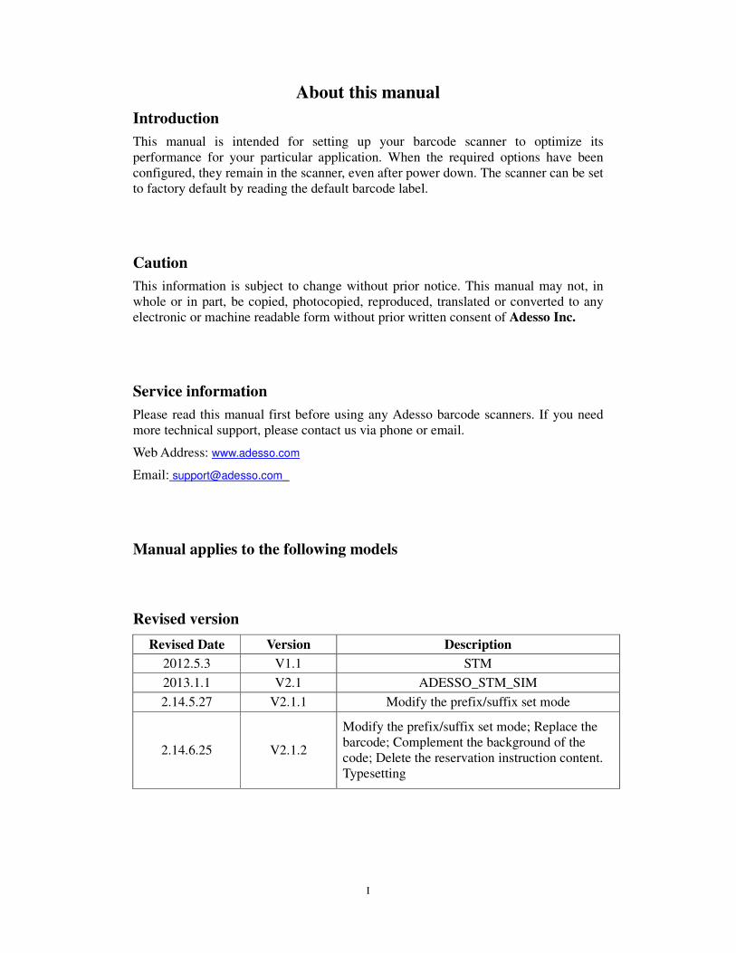
About this manual
Introduction
This manual is intended for setting up your barcode scanner to optimize its performance for your particular application. When the required options have been configured, they remain in the scanner, even after power down. The scanner can be set to factory default by reading the default barcode label.
Caution
This information is subject to change without prior notice. This manual may not, in whole or in part, be copied, photocopied, reproduced, translated or converted to any electronic or machine readable form without prior written consent of Adesso Inc.
Service information
Please read this manual first before using any Adesso barcode scanners. If you need more technical support, please contact us via phone or email.
Web Address: www.adesso.com
Email: [email protected]
Manual applies to the following models
Revised version
Revised Date Version Description
2012.5.3 V1.1 STM
2013.1.1 V2.1 ADESSO_STM_SIM
2.14.5.27 V2.1.1 Modify the prefix/suffix set mode
2.14.6.25 V2.1.2
Modify the prefix/suffix set mode; Replace the barcode; Complement the background of the code; Delete the reservation instruction content. Typesetting

1
1. Product Specifications
1.1 Technical parameters
Details can be referred to the related product brochures.
2
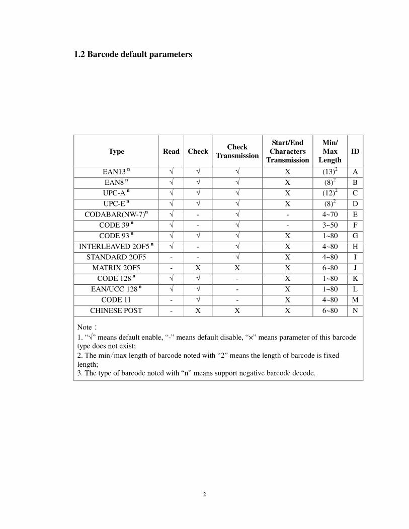
1.2 Barcode default parameters
Type Read Check Check
Transmission
Start/End Characters
Transmission
Min/ Max
Length ID
EAN13 n √ √ √ X (13)2 A
EAN8 n √ √ √ X (8)2 B
UPC-A n √ √ √ X (12)2 C
UPC-E n √ √ √ X (8)2 D
CODABAR(NW-7)n √ - √ - 4~70 E
CODE 39 n √ - √ - 3~50 F
CODE 93 n √ √ √ X 1~80 G
INTERLEAVED 2OF5 n √ - √ X 4~80 H
STANDARD 2OF5 - - √ X 4~80 I
MATRIX 2OF5 - X X X 6~80 J
CODE 128 n √ √ - X 1~80 K
EAN/UCC 128 n √ √ - X 1~80 L
CODE 11 - √ - X 4~80 M
CHINESE POST - X X X 6~80 N
Note:
1. “√” means default enable, “-” means default disable, “×” means parameter of this barcode type does not exist;
2. The min/max length of barcode noted with “2” means the length of barcode is fixed
length; 3. The type of barcode noted with “n” means support negative barcode decode.

3
1.3 Interface specifications
All Netum readers can be equipped with USB Keyboard, TTL/RS232 (DB9 female), RS485 (DB9 male), PS2 keyboard or any other customized interfaces. Different product’s standard interface is different. So please confirm it before purchase. Other interfaces can be customized according to customer’s demand.
4
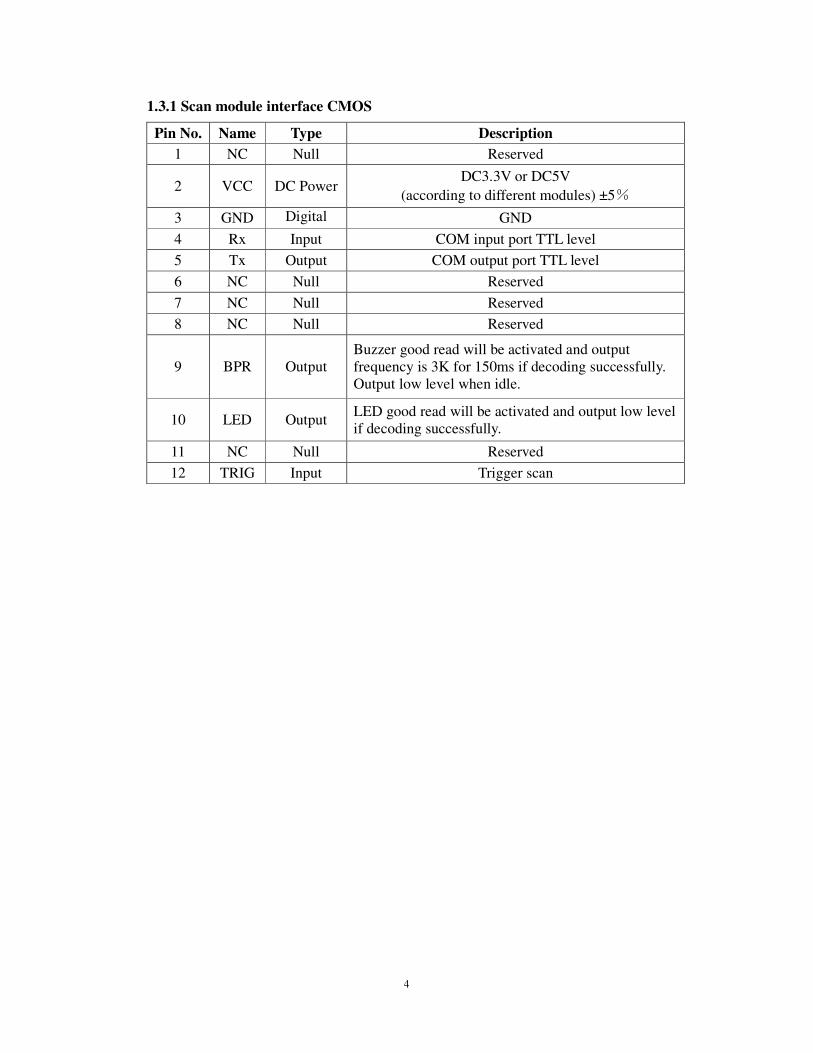
1.3.1 Scan module interface CMOS
Pin No. Name Type Description
1 NC Null Reserved
2 VCC DC Power DC3.3V or DC5V
(according to different modules) ±5%
3 GND Digital Ground
GND
4 Rx Input COM input port TTL level
5 Tx Output COM output port TTL level
6 NC Null Reserved
7 NC Null Reserved
8 NC Null Reserved
9 BPR Output Buzzer good read will be activated and output frequency is 3K for 150ms if decoding successfully. Output low level when idle.
10 LED Output LED good read will be activated and output low level if decoding successfully.
11 NC Null Reserved
12 TRIG Input Trigger scan

5
1.3.2 Scan engine interface without decoding
Interface circuit is a ZIP (0.5mm-8p) interface which communicates with outside world. It’s the microprocessor that controls the scan engine’s work and takes the data to decode.
Pin NO. Pin Name Description
1、2 GND Ground
3 SOS
Scan starting signal: When the laser line reaches the edge, the signal will transform from high to low or from low to high in order to detect the start and finish of a scan.
4 DATA The width of the DATA signal stands for the width of black and white bars. The output is CMOS level. High level=Bars, Low level=Spaces
5 TRIG
Allowing Trigger scanning signal: TRIG=High: The scan engine will enter a power-saving mode; TRIG=Low: The scan circuit will be activated to the ready state.
6 LASER-EN
Activation signal LASER-EN=High or not connected: The laser will be closed; LASER-EN=Low and TRIG=Low: The scan engine circuit will be activated and ready to scan barcodes. The laser will open.
7 IR-TRIG Optional, IR trigger pin, only for WSL3000
8 VCC Power Supply: DC 5V

6
1.3.3 Standard serial port (DB9)
NO. Function
1 Trigger(optional)
2 Rx
3 Tx
5 GND
9 DC 5V(optional)
When pin 1 receives low level for 10ms, it means trigger and scan. (optional)
Pin 6 is only used in trigger mode. It will output low level for 100ms if it detects no barcode after trigger. (value added service)
7
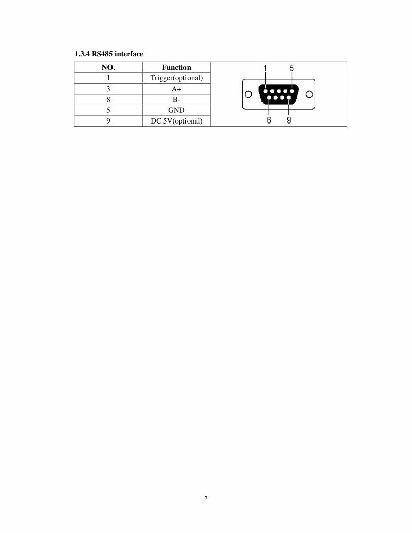
1.3.4 RS485 interface
NO. Function
1 Trigger(optional)
3 A+
8 B-
5 GND
9 DC 5V(optional)
8
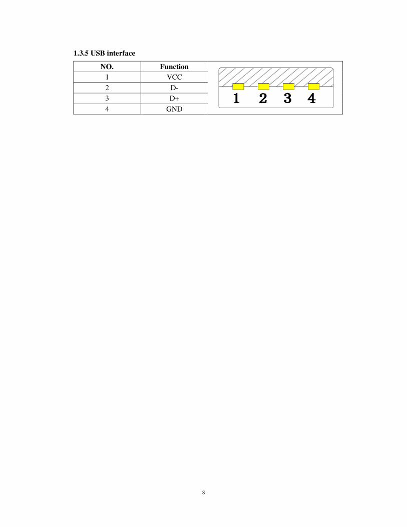
1.3.5 USB interface
NO. Function
1 VCC
2 D-
3 D+
4 GND

9
1.3.6 PS2 Keyboard wedge
Omission
10
2. Command instructions
2.1 Barcode command instructions
A. Command barcodes are printed via Code 128 CODE B barcode set. Command
barcode is same as serial port command value(Detail as Chart 2.2-1).
B. Note with “*” means factory default parameter.
(a) “%SET”: Enter setting mode; It will drop out setting mode automatically if it not scans next command barcode in 30s; (b) Modify parameters command: It can scan one or several command barcodes; (c) “%END”: Save & Exit.
11
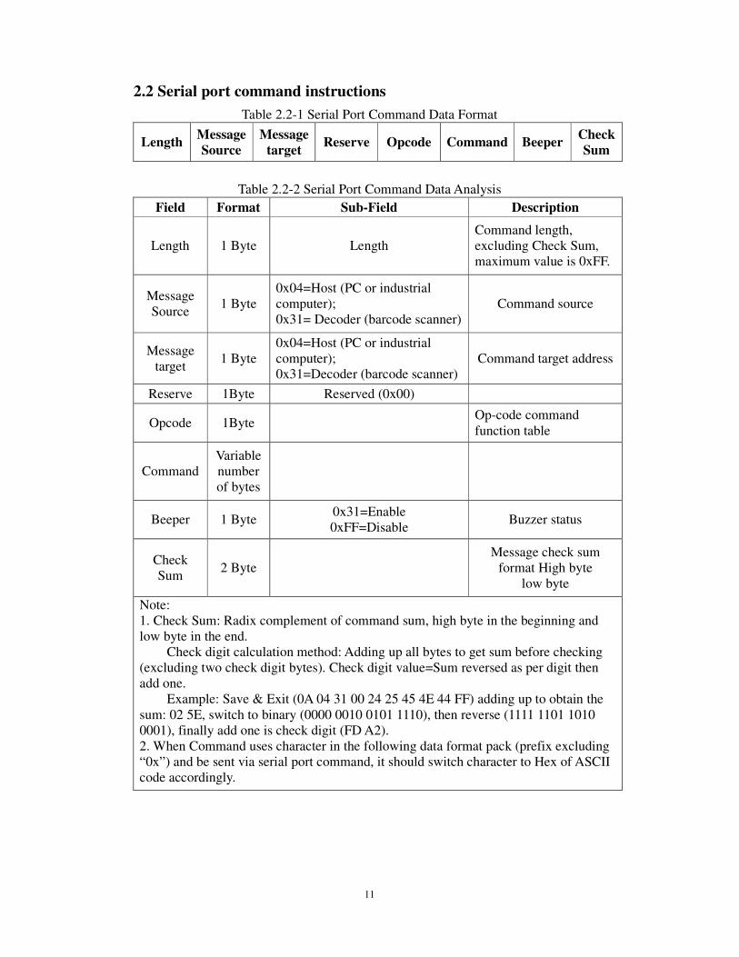
2.2 Serial port command instructions
Table 2.2-1 Serial Port Command Data Format
Length Message Source
Message target
Reserve Opcode Command Beeper Check Sum
Table 2.2-2 Serial Port Command Data Analysis
Field Format Sub-Field Description
Length 1 Byte Length Command length, excluding Check Sum, maximum value is 0xFF.
Message Source
1 Byte 0x04=Host (PC or industrial computer); 0x31= Decoder (barcode scanner)
Command source
Message target
1 Byte 0x04=Host (PC or industrial computer); 0x31=Decoder (barcode scanner)
Command target address
Reserve 1Byte Reserved (0x00)
Opcode 1Byte Op-code command function table
Command Variable number of bytes
Beeper 1 Byte 0x31=Enable 0xFF=Disable
Buzzer status
Check Sum
2 Byte Message check sum
format High byte low byte
Note: 1. Check Sum: Radix complement of command sum, high byte in the beginning and low byte in the end.
Check digit calculation method: Adding up all bytes to get sum before checking (excluding two check digit bytes). Check digit value=Sum reversed as per digit then add one.
Example: Save & Exit (0A 04 31 00 24 25 45 4E 44 FF) adding up to obtain the sum: 02 5E, switch to binary (0000 0010 0101 1110), then reverse (1111 1101 1010 0001), finally add one is check digit (FD A2). 2. When Command uses character in the following data format pack (prefix excluding “0x”) and be sent via serial port command, it should switch character to Hex of ASCII code accordingly.
12
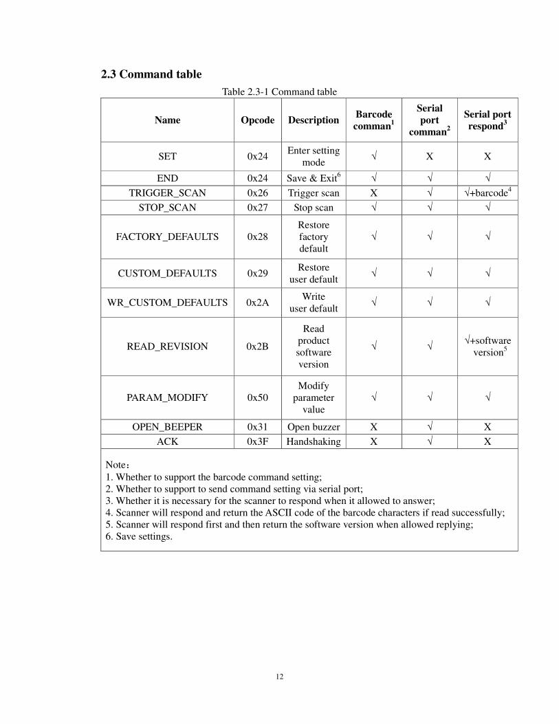
2.3 Command table
Table 2.3-1 Command table
Name Opcode Description Barcode comman1
Serial port
comman2
Serial port respond3
SET 0x24 Enter setting
mode √ X X
END 0x24 Save & Exit6 √ √ √
TRIGGER_SCAN 0x26 Trigger scan X √ √+barcode4
STOP_SCAN 0x27 Stop scan √ √ √
FACTORY_DEFAULTS 0x28 Restore factory default
√ √ √
CUSTOM_DEFAULTS 0x29 Restore
user default √ √ √
WR_CUSTOM_DEFAULTS 0x2A Write
user default √ √ √
READ_REVISION 0x2B
Read product software version
√ √ √+software
version5
PARAM_MODIFY 0x50 Modify
parameter value
√ √ √
OPEN_BEEPER 0x31 Open buzzer X √ X
ACK 0x3F Handshaking X √ X
Note:
1. Whether to support the barcode command setting; 2. Whether to support to send command setting via serial port; 3. Whether it is necessary for the scanner to respond when it allowed to answer; 4. Scanner will respond and return the ASCII code of the barcode characters if read successfully; 5. Scanner will respond first and then return the software version when allowed replying; 6. Save settings.

13
2.4 Quick command (HEX format)
Quick command can be used in the following conditions: Message Source=0x04 (PC or Industrial Computer); Message target=0x31 (barcode scanner 0x31); Beeper=0xFF (Closed).
Table 2.4-1 Host to Scanner
Function Command(HEX format)
Common command:
Save & Exit (%END) 0A 04 31 00 24 25 45 4E 44 FF FD A2
Trigger scan (LT) 08 04 31 00 26 4C 54 FF FD FE
Stop scan (LS) 08 04 31 00 27 4C 53 FF FD FE
Restore factory default (DF) 08 04 31 00 28 44 46 FF FE 12
Restore user default (DC) 08 04 31 00 29 44 43 FF FE 14
Write user default (WC) 08 04 31 00 2A 57 43 FF FE 00
Read product batch version (RV) 08 04 31 00 2B 52 56 FF FD F1
Modify parameter command:
Single read (F0000) 0B 04 31 00 50 46 30 30 30 30 FF FD 6B
Continuous read (F0001) 0B 04 31 00 50 46 30 30 30 31 FF FD 6A
Disable repeat read (F0100) 0B 04 31 00 50 46 30 31 30 30 FF FD 6A
Enable repeat read (F0101) 0B 04 31 00 50 46 30 31 30 31 FF FD 69
Multiple read (F0102) 0B 04 31 00 50 46 30 31 30 32 FF FD 68
TTL/RS232 output (A0000) 0B 04 31 00 50 41 30 30 30 30 FF FD 70
USB HID Keyboard output (A0001) 0B 04 31 00 50 41 30 30 30 31 FF FD 6F
Disable respond (E0000) 0B 04 31 00 50 45 30 30 30 30 FF FD 6C
Enable respond (E0001) 0B 04 31 00 50 45 30 30 30 31 FF FD 6B
Disable transmit NR (G0000) 0B 04 31 00 50 47 30 30 30 30 FF FD 6A
Enable transmit NR (G0001) 0B 04 31 00 50 47 30 30 30 31 FF FD 69
Enable transmit NR (protocol) (G0002) 0B 04 31 00 50 47 30 30 30 32 FF FD 68
Disable read all barcodes (I1000) 0B 04 31 00 50 49 31 30 30 30 FF FD 67
Enable read all barcodes (I1001) 0B 04 31 00 50 49 31 30 30 31 FF FD 66
Table 2.4-2 Scanner to Host
Function Command(HEX format)
Respond if setting succeed 07 31 04 00 01 06 FF FE BE
Respond if setting fail 07 31 04 00 01 15 FF FE AF
Enable transmit NR (protocol) 08 31 04 00 02 4E 52 FF FE 22

14
3. General command data format
3.1 SET & END
Data format:
Length Message Source
Message target
Reserve Opcode Command beeper Check Sum
0x0A 0x04 0x31 0x00 0x24 %END
Command:
Enter setting mode %SET
Save & Exit %END
15
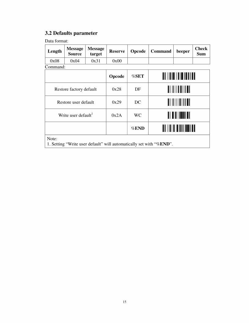
3.2 Defaults parameter
Data format:
Command:
Opcode %SET
Restore factory default 0x28 DF
Restore user default 0x29 DC
Write user default1 0x2A WC
%END
Note: 1. Setting “Write user default” will automatically set with “%END”.
Length Message Source
Message target
Reserve Opcode Command beeper Check Sum
0x08 0x04 0x31 0x00

16
3.3 TRIGGER_SCAN & STOP_SCAN
Data format:
Length Message Source
Message target
Reserve Opcode Command beeper Check Sum
0x08 0x04 0x31 0x00
Command:
Opcode %SET
Trigger scan 0x26 LT
Stop scan 0x27 LS
%END
17
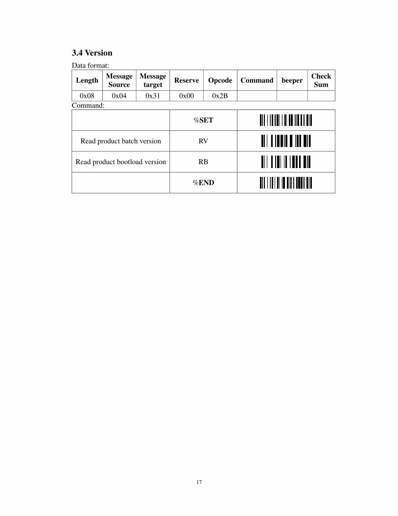
3.4 Version
Data format:
Length Message Source
Message target
Reserve Opcode Command beeper Check Sum
0x08 0x04 0x31 0x00 0x2B
Command:
%SET
Read product batch version RV
Read product bootload version RB
%END
18
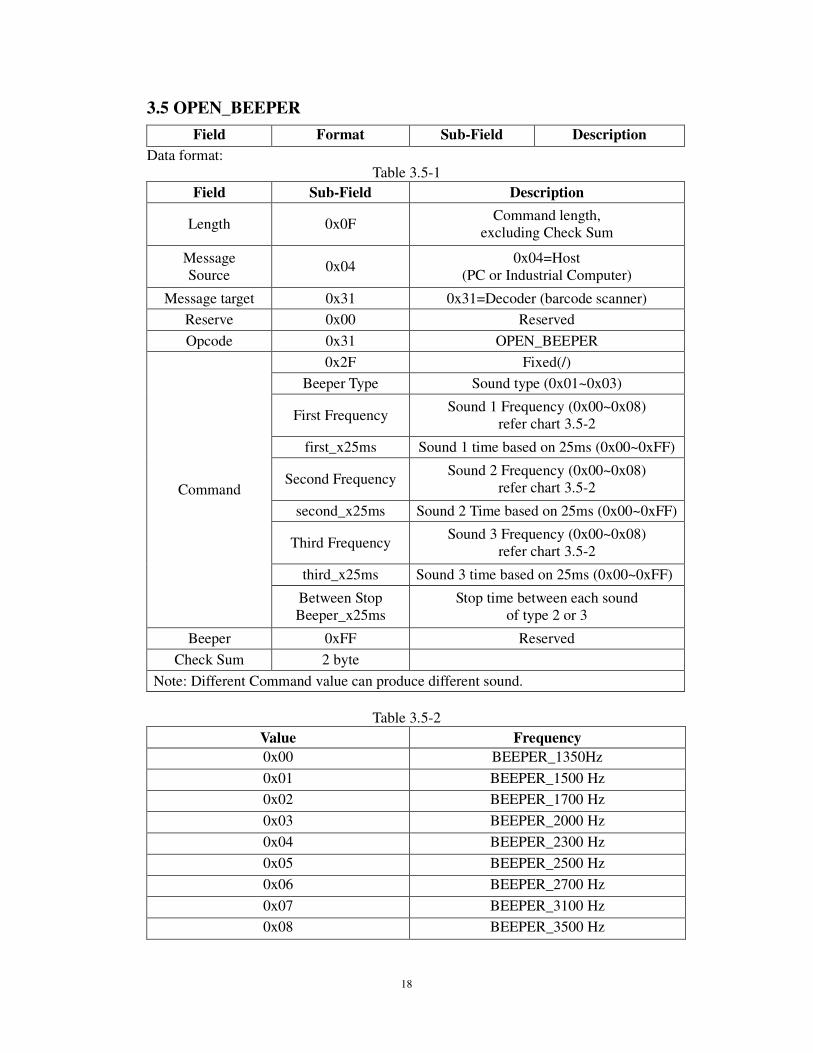
3.5 OPEN_BEEPER
Field Format Sub-Field Description
Data format: Table 3.5-1
Field Sub-Field Description
Length 0x0F Command length,
excluding Check Sum
Message Source
0x04 0x04=Host
(PC or Industrial Computer)
Message target 0x31 0x31=Decoder (barcode scanner)
Reserve 0x00 Reserved
Opcode 0x31 OPEN_BEEPER
Command
0x2F Fixed(/)
Beeper Type Sound type (0x01~0x03)
First Frequency Sound 1 Frequency (0x00~0x08)
refer chart 3.5-2
first_x25ms Sound 1 time based on 25ms (0x00~0xFF)
Second Frequency Sound 2 Frequency (0x00~0x08)
refer chart 3.5-2
second_x25ms Sound 2 Time based on 25ms (0x00~0xFF)
Third Frequency Sound 3 Frequency (0x00~0x08)
refer chart 3.5-2
third_x25ms Sound 3 time based on 25ms (0x00~0xFF)
Between Stop Beeper_x25ms
Stop time between each sound of type 2 or 3
Beeper 0xFF Reserved
Check Sum 2 byte
Note: Different Command value can produce different sound.
Table 3.5-2
Value Frequency
0x00 BEEPER_1350Hz
0x01 BEEPER_1500 Hz
0x02 BEEPER_1700 Hz
0x03 BEEPER_2000 Hz
0x04 BEEPER_2300 Hz
0x05 BEEPER_2500 Hz
0x06 BEEPER_2700 Hz
0x07 BEEPER_3100 Hz
0x08 BEEPER_3500 Hz
19
Example 1 (hex): ring 3 times
Sound 1 (2500Hz), last for 100ms; sound 2 (1500Hz), last for 100ms; sound 3 (2500Hz), last for 100ms; stop time between each sound is 250ms. Setting command: 0F 04 31 00 31 2F 03 05 04 01 04 05 04 0A FF FE 39
Example 2 (hex): ring once
Sound 1 (2500Hz), last for 250ms; sound 2 (1350Hz), last for 0ms; sound 3 (1350Hz), last for 0ms; stop time between each sound is 0ms. Setting command: 0F 04 31 00 31 2F 01 05 0A 00 00 00 00 00 FF FE 4D If set to ring once, the frequency of sound 2 and 3 will be invalid; last time and stop time between each sound should be set at 0ms.
20
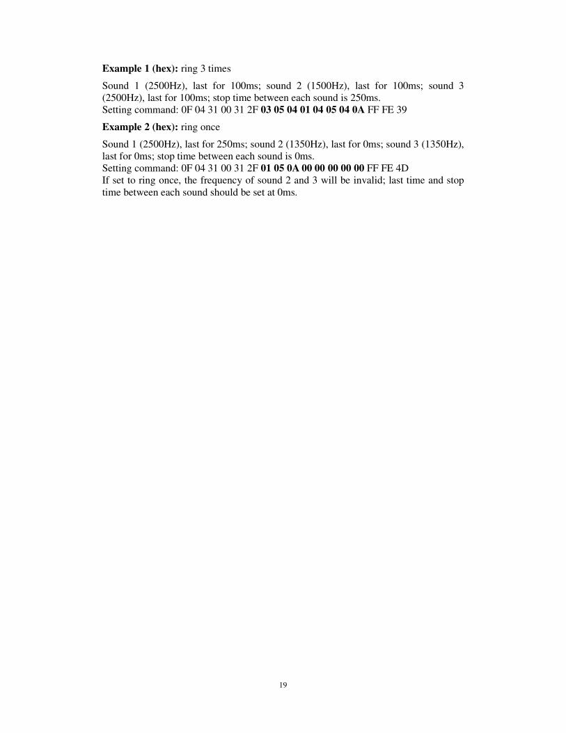
3.6 ACK Handshaking
Data format:
Length Message Source
Message target
Reserve Opcode Command beeper Check Sum
0x07 0x04 0x31 0x00 0x3F 0x2F
Scanner->Host: handshaking respond (protocol) data format:
Length Message Source
Message target
Reserve Opcode data beeper Check Sum
0x0D 0x31 0x04 0x00 0x3F ND-V201 0xFF
Example (hex):
Host->Scanner: 07 04 31 00 3F 2F FF FE 57
Scanner->Host: 0D 31 04 00 3F 4E 44 2D 56 32 30 31 FF FC D8
21
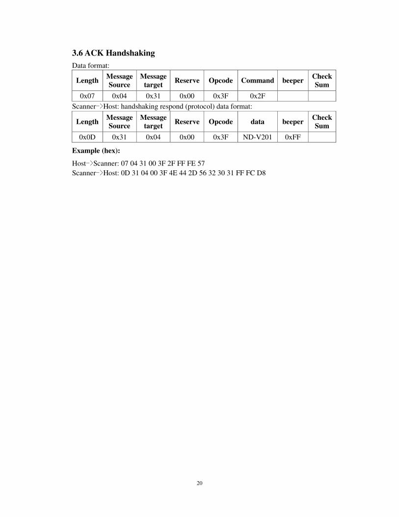
4. Modify parameters command
4.1 Data output mode
Data format:
Length Message Source
Message target
Reserve Opcode Command beeper Check Sum
0x0B 0x04 0x31 0x00 0x50
Command:
%SET
*TTL/RS232 A0000
*USB HID Keyboard A0001
USB virtual com port A0002
USB HID communication A0003
RS485 A0004
PS2 Keyboard A0005
%END
22
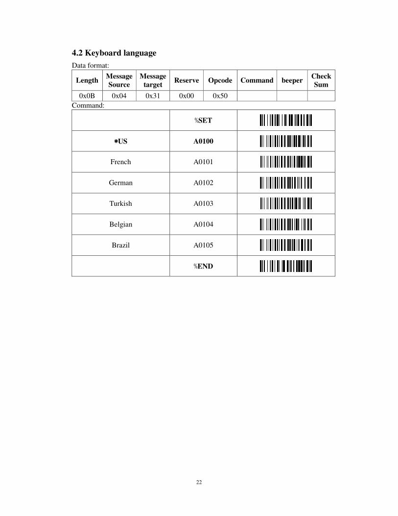
4.2 Keyboard language
Data format:
Length Message Source
Message target
Reserve Opcode Command beeper Check Sum
0x0B 0x04 0x31 0x00 0x50
Command:
%SET
****US A0100
French A0101
German A0102
Turkish A0103
Belgian A0104
Brazil A0105
%END
23
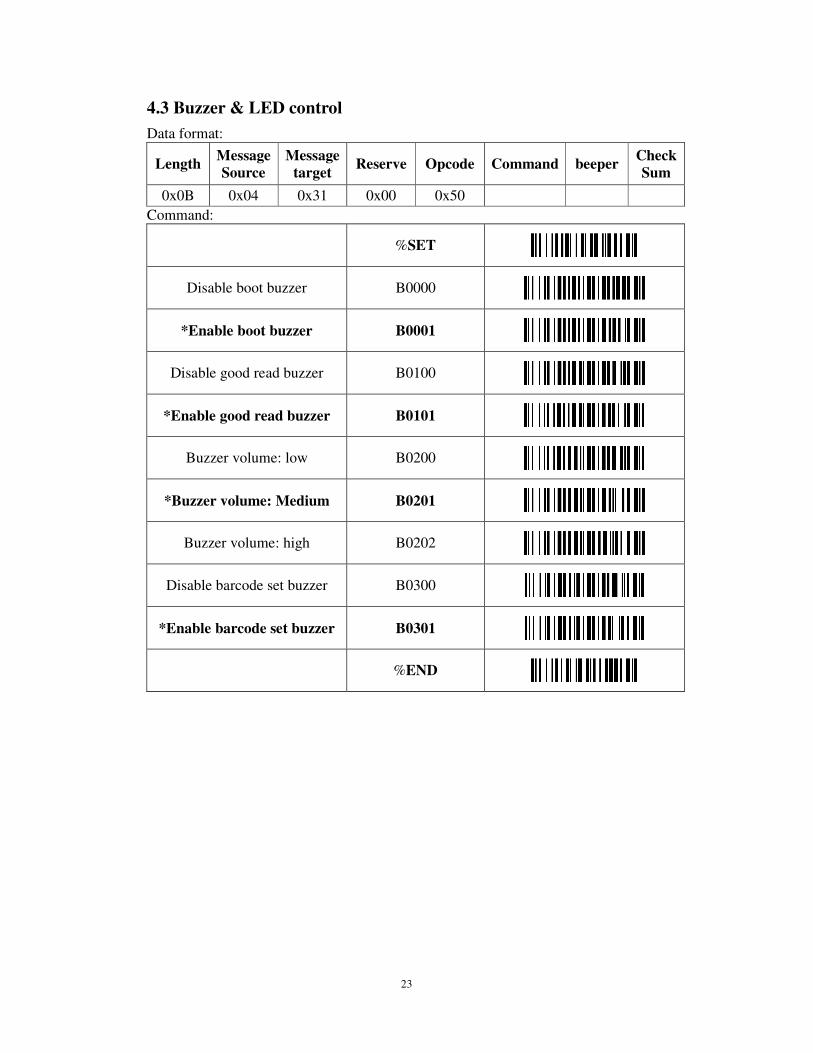
4.3 Buzzer & LED control
Data format:
Length Message Source
Message target
Reserve Opcode Command beeper Check Sum
0x0B 0x04 0x31 0x00 0x50
Command:
%SET
Disable boot buzzer B0000
*Enable boot buzzer B0001
Disable good read buzzer B0100
*Enable good read buzzer B0101
Buzzer volume: low B0200
*Buzzer volume: Medium B0201
Buzzer volume: high B0202
Disable barcode set buzzer B0300
*Enable barcode set buzzer B0301
%END

24
4.4 Serial port setting
Data format:
Length Message Source
Message target
Reserve Opcode Command beeper Check Sum
0x0B 0x04 0x31 0x00 0x50
The baud rate is the rate at which bits are transmitted from the reader to the host, and vice verse. Both the reader and the host should be set to the same baud rate.
The data characters may be transferred in one of the following formats:
A parity bit may be added to every character so that the total number of 1’s in the data bits, together with the parity bit, is odd for odd parity or even for even parity.
Command:
%SET
2400 baud C0000
4800 baud C0001
*9600 baud C0002
19200 baud C0003
38400 baud C0004
57600 baud C0005
115200 baud C0006
7 data bits C0100
*8 data bits C0101
*1 stop bit C0200
2 stop bit C0201
*No parity C0300
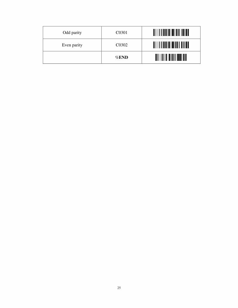
25
Odd parity C0301
Even parity C0302
%END
26
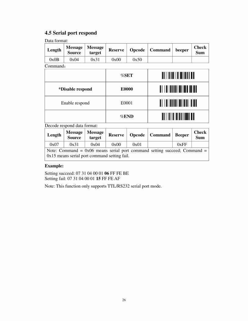
4.5 Serial port respond
Data format:
Length Message Source
Message target
Reserve Opcode Command beeper Check Sum
0x0B 0x04 0x31 0x00 0x50
Command:
%SET
*Disable respond E0000
Enable respond E0001
%END
Decode respond data format:
Length Message Source
Message target
Reserve Opcode Command Beeper Check Sum
0x07 0x31 0x04 0x00 0x01 0xFF
Note: Command = 0x06 means serial port command setting succeed; Command = 0x15 means serial port command setting fail.
Example:
Setting succeed: 07 31 04 00 01 06 FF FE BE Setting fail: 07 31 04 00 01 15 FF FE AF
Note: This function only supports TTL/RS232 serial port mode.
27
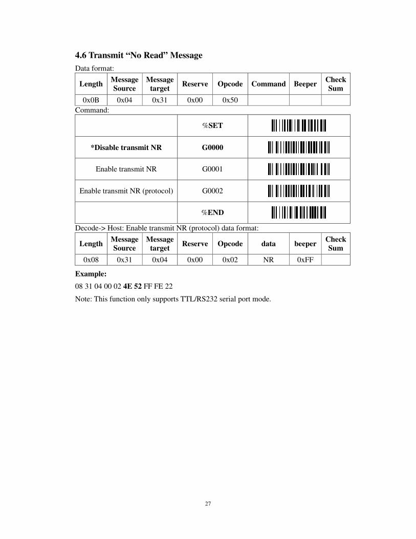
4.6 Transmit “No Read” Message
Data format:
Length Message Source
Message target
Reserve Opcode Command Beeper Check Sum
0x0B 0x04 0x31 0x00 0x50
Command:
%SET
*Disable transmit NR G0000
Enable transmit NR G0001
Enable transmit NR (protocol) G0002
%END
Decode-> Host: Enable transmit NR (protocol) data format:
Length Message Source
Message target
Reserve Opcode data beeper Check Sum
0x08 0x31 0x04 0x00 0x02 NR 0xFF
Example:
08 31 04 00 02 4E 52 FF FE 22
Note: This function only supports TTL/RS232 serial port mode.
28
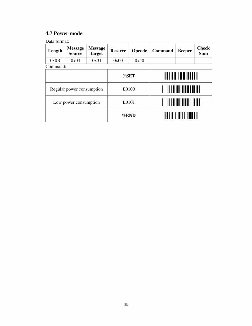
4.7 Power mode
Data format:
Length Message Source
Message target
Reserve Opcode Command Beeper Check Sum
0x0B 0x04 0x31 0x00 0x50
Command:
%SET
Regular power consumption E0100
Low power consumption E0101
%END
29
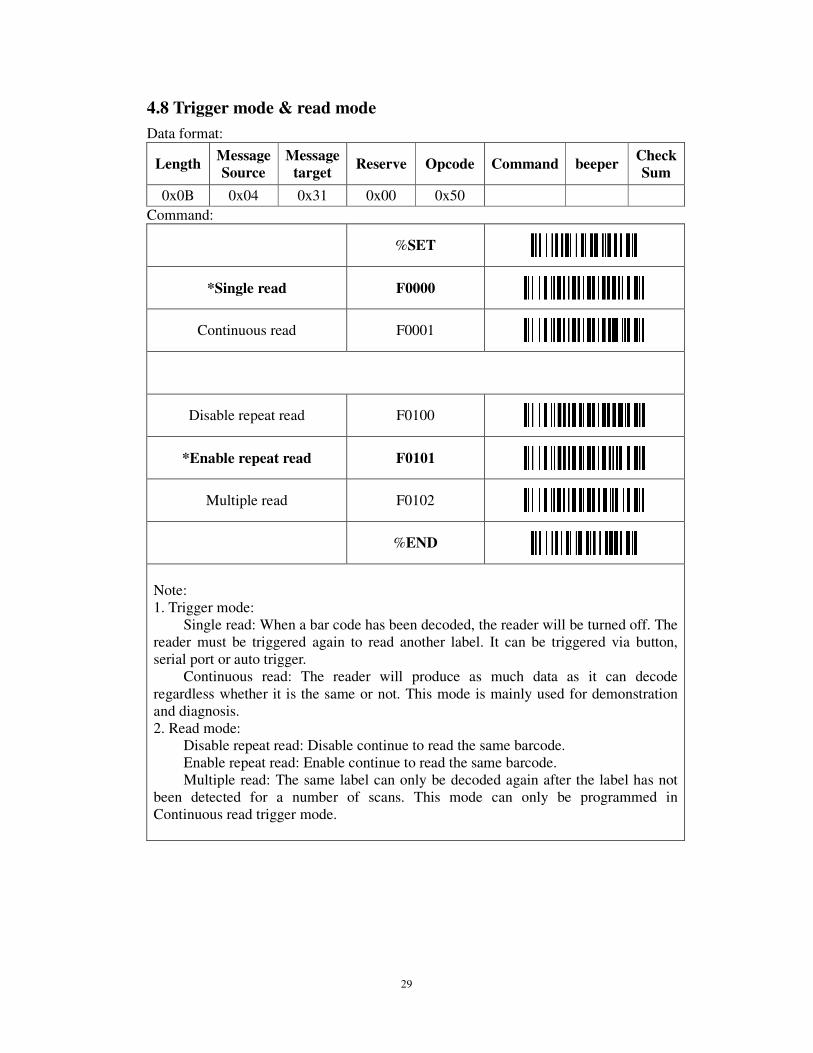
4.8 Trigger mode & read mode
Data format:
Length Message Source
Message target
Reserve Opcode Command beeper Check Sum
0x0B 0x04 0x31 0x00 0x50
Command:
%SET
*Single read F0000
Continuous read F0001
Disable repeat read F0100
*Enable repeat read F0101
Multiple read F0102
%END
Note: 1. Trigger mode:
Single read: When a bar code has been decoded, the reader will be turned off. The reader must be triggered again to read another label. It can be triggered via button, serial port or auto trigger.
Continuous read: The reader will produce as much data as it can decode regardless whether it is the same or not. This mode is mainly used for demonstration and diagnosis. 2. Read mode:
Disable repeat read: Disable continue to read the same barcode. Enable repeat read: Enable continue to read the same barcode. Multiple read: The same label can only be decoded again after the label has not
been detected for a number of scans. This mode can only be programmed in Continuous read trigger mode.
30
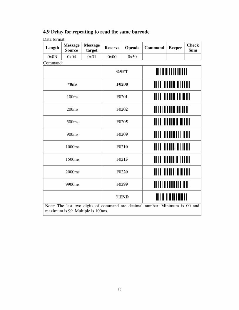
4.9 Delay for repeating to read the same barcode
Data format:
Length Message Source
Message target
Reserve Opcode Command Beeper Check Sum
0x0B 0x04 0x31 0x00 0x50
Command:
%SET
*0ms F0200
100ms F0201
200ms F0202
500ms F0205
900ms F0209
1000ms F0210
1500ms F0215
2000ms F0220
9900ms F0299
%END
Note: The last two digits of command are decimal number. Minimum is 00 and maximum is 99. Multiple is 100ms.

31
4.10 Light delay after triggering the scanner caused by the trigger pin
Data format:
Length Message Source
Message target
Reserve Opcode Command Beeper Check Sum
0x0B 0x04 0x31 0x00 0x50
Command:
%SET
*0ms F0300
100ms F0301
200ms F0302
500ms F0305
900ms F0309
1000ms F0310
1500ms F0315
2000ms F0320
4000ms F0340
6000ms F0360
9900ms F0399
%END
Note: 1. The last two digits of command are decimal number. Minimum is 00 and maximum is 99. Multiple is 100ms. 2. When trigger scan waiting time is 0ms with low level signal, it will continuously scan unless decode or high level signal. There will be no overtime under this condition. 3. When trigger scan waiting time is not 0ms, it will start to scan with low level signal. It will automatically time out and stop scanning if not decode in the required waiting time.
32
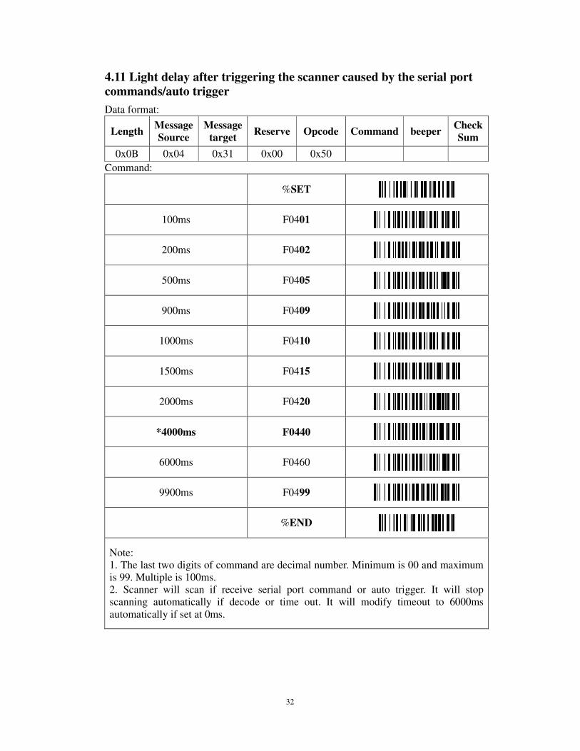
4.11 Light delay after triggering the scanner caused by the serial port commands/auto trigger
Data format:
Length Message Source
Message target
Reserve Opcode Command beeper Check Sum
0x0B 0x04 0x31 0x00 0x50
Command:
%SET
100ms F0401
200ms F0402
500ms F0405
900ms F0409
1000ms F0410
1500ms F0415
2000ms F0420
*4000ms F0440
6000ms F0460
9900ms F0499
%END
Note: 1. The last two digits of command are decimal number. Minimum is 00 and maximum is 99. Multiple is 100ms. 2. Scanner will scan if receive serial port command or auto trigger. It will stop scanning automatically if decode or time out. It will modify timeout to 6000ms automatically if set at 0ms.
33
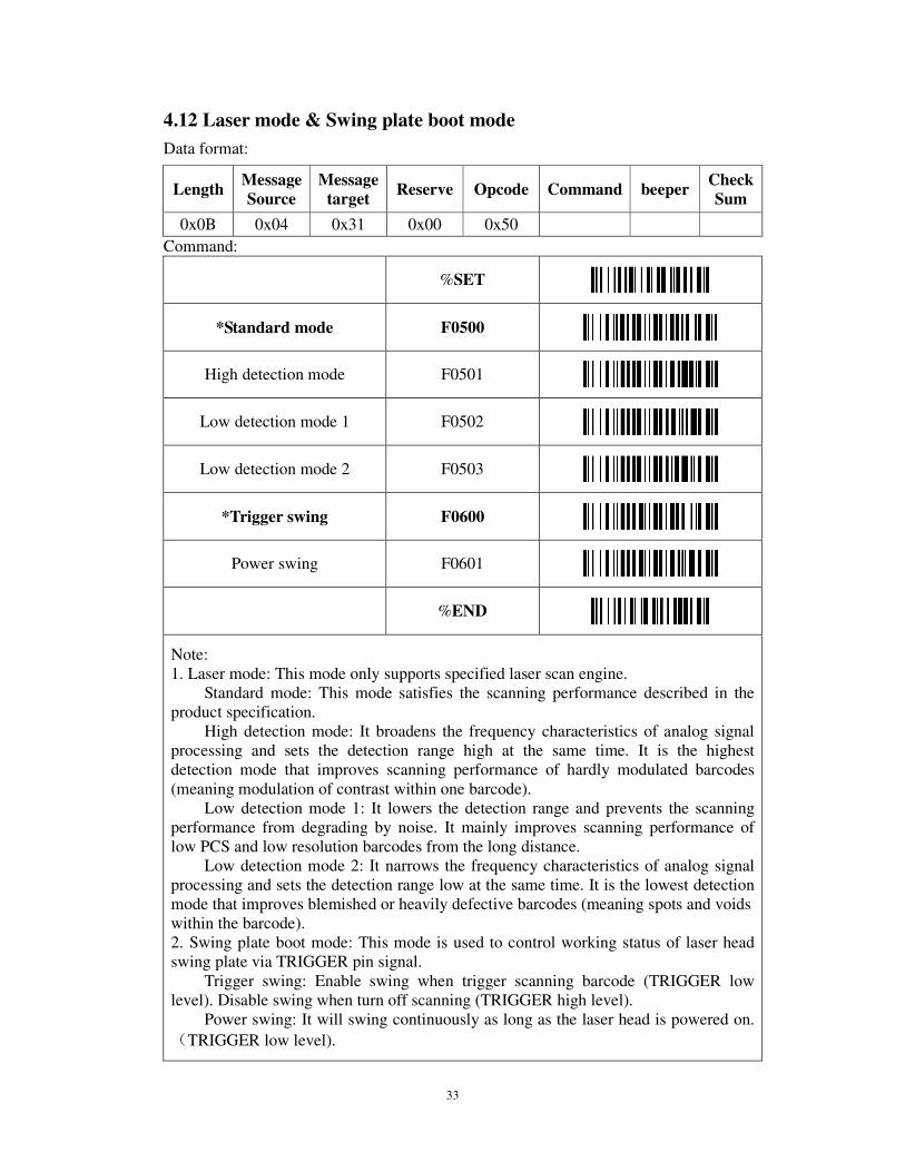
4.12 Laser mode & Swing plate boot mode
Data format:
Command:
%SET
*Standard mode F0500
High detection mode F0501
Low detection mode 1 F0502
Low detection mode 2 F0503
*Trigger swing F0600
Power swing F0601
%END
Note: 1. Laser mode: This mode only supports specified laser scan engine.
Standard mode: This mode satisfies the scanning performance described in the product specification.
High detection mode: It broadens the frequency characteristics of analog signal processing and sets the detection range high at the same time. It is the highest detection mode that improves scanning performance of hardly modulated barcodes (meaning modulation of contrast within one barcode).
Low detection mode 1: It lowers the detection range and prevents the scanning performance from degrading by noise. It mainly improves scanning performance of low PCS and low resolution barcodes from the long distance.
Low detection mode 2: It narrows the frequency characteristics of analog signal processing and sets the detection range low at the same time. It is the lowest detection mode that improves blemished or heavily defective barcodes (meaning spots and voids within the barcode). 2. Swing plate boot mode: This mode is used to control working status of laser head swing plate via TRIGGER pin signal.
Trigger swing: Enable swing when trigger scanning barcode (TRIGGER low level). Disable swing when turn off scanning (TRIGGER high level).
Power swing: It will swing continuously as long as the laser head is powered on.
(TRIGGER low level).
Length Message Source
Message target
Reserve Opcode Command beeper Check Sum
0x0B 0x04 0x31 0x00 0x50

34
4.13 Auto trigger
Data format:
Length Message Source
Message target
Reserve Opcode Command beeper Check Sum
0x0B 0x04 0x31 0x00 0x50
Command:
%SET
Disable H0000
*Enable H0001
%END
35
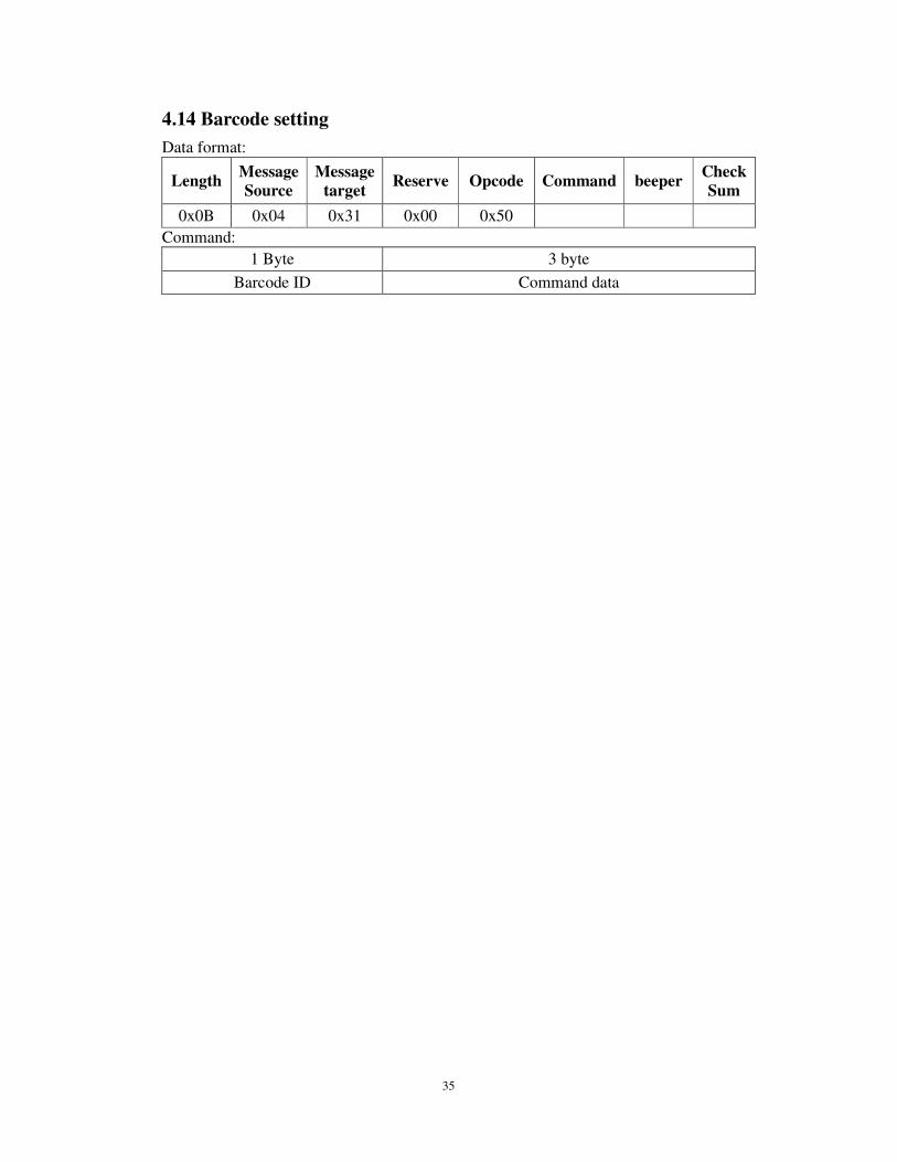
4.14 Barcode setting
Data format:
Length Message Source
Message target
Reserve Opcode Command beeper Check Sum
0x0B 0x04 0x31 0x00 0x50
Command:
1 Byte 3 byte
Barcode ID Command data
36
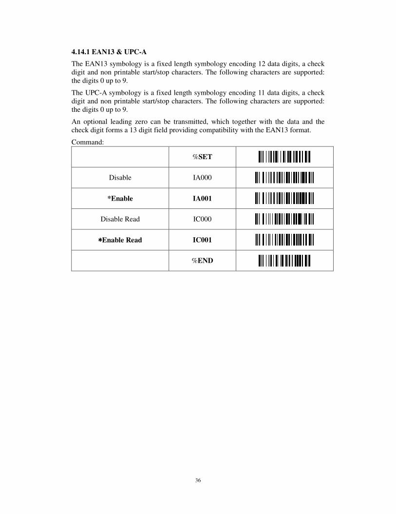
4.14.1 EAN13 & UPC-A
The EAN13 symbology is a fixed length symbology encoding 12 data digits, a check digit and non printable start/stop characters. The following characters are supported: the digits 0 up to 9.
The UPC-A symbology is a fixed length symbology encoding 11 data digits, a check digit and non printable start/stop characters. The following characters are supported: the digits 0 up to 9.
An optional leading zero can be transmitted, which together with the data and the check digit forms a 13 digit field providing compatibility with the EAN13 format.
Command:
%SET
Disable IA000
*Enable IA001
Disable Read IC000
****Enable Read IC001
%END
37
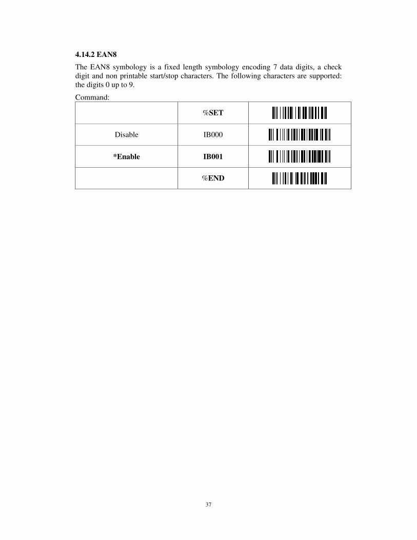
4.14.2 EAN8
The EAN8 symbology is a fixed length symbology encoding 7 data digits, a check digit and non printable start/stop characters. The following characters are supported: the digits 0 up to 9.
Command:
%SET
Disable IB000
*Enable IB001
%END

38
4.14.3 UPC-E
The UPC-E symbology is a fixed length symbology encoding 6 data digits, a check digit and non printable start/stop characters. The following characters are supported: the digits 0 up to 9.
An optional leading digit can be transmitted, which together with the data and the check digit forms a 8 digit field providing compatibility with the EAN8 format.
Command :
%SET
Disable ID000
*Enable ID001
Enable UPC-E convert to UPC-A
ID100
*Disable UPC-E convert to UPC-A
ID101
%END
39
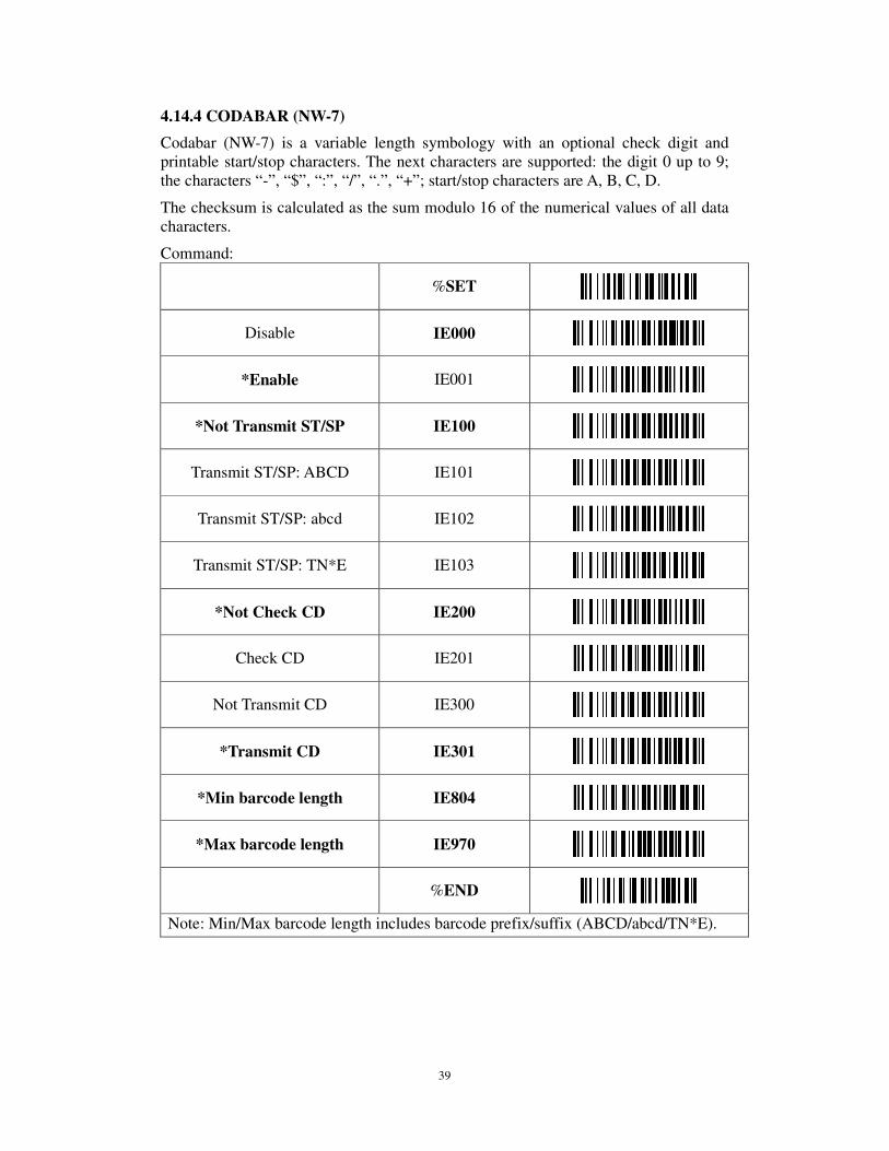
4.14.4 CODABAR (NW-7)
Codabar (NW-7) is a variable length symbology with an optional check digit and printable start/stop characters. The next characters are supported: the digit 0 up to 9; the characters “-”, “$”, “:”, “/”, “.”, “+”; start/stop characters are A, B, C, D.
The checksum is calculated as the sum modulo 16 of the numerical values of all data characters.
Command:
%SET
Disable IE000
*Enable IE001
*Not Transmit ST/SP IE100
Transmit ST/SP: ABCD IE101
Transmit ST/SP: abcd IE102
Transmit ST/SP: TN*E IE103
*Not Check CD IE200
Check CD IE201
Not Transmit CD IE300
*Transmit CD IE301
*Min barcode length IE804
*Max barcode length IE970
%END
Note: Min/Max barcode length includes barcode prefix/suffix (ABCD/abcd/TN*E).

40
Codabar Min/Max barcode length
%SET
Min barcode length(5) IE805
Min barcode length(6) IE806
Min barcode length(7) IE807
Min barcode length(8) IE808
Min barcode length(10) IE810
Min barcode length(12) IE812
Min barcode length(14) IE814
Min barcode length(16) IE816
Max barcode length(10) IE910
Max barcode length(12) IE912
Max barcode length(14) IE914
Max barcode length(16) IE916
Max barcode length(18) IE918
Max barcode length(20) IE920
Max barcode length(22) IE922
Max barcode length(24) IE924
%END

41
4.14.5 CODE 39
Code 39 is a variable length symbology with an optional check digit and printable start/stop characters. The following characters are supported: the digit 0 up to 9; the upper case characters A up to Z; the characters “-”, “$”, “%”, “/”, “.”, “+”, SPACE; start/stop character is “*”.
The checksum is calculated as the sum modulo 43 of the numerical values of the data characters. In full ASCII mode, all 128 ASCII characters are supported. This is done by combining one of the characters “$”, “%”, “+” or “/” with one of the alpha characters (A up to Z).
Command:
%SET
Disable IF000
*Enable IF001
*Not Transmit ST/SP IF100
Transmit ST/SP: * IF101
*Not Check CD IF200
Check CD IF201
Not Transmit CD IF300
*Transmit CD IF301
*Disable Full ASCII code39 IF400
Enable Full ASCII code39 IF401
*Min barcode length IF803
*Max barcode length IF950
*Disable Code39 convert to Code32 (Italian Pharmacode)
IF500
Enable Code39 convert to Code32 (Italian Pharmacode)
IF501
42
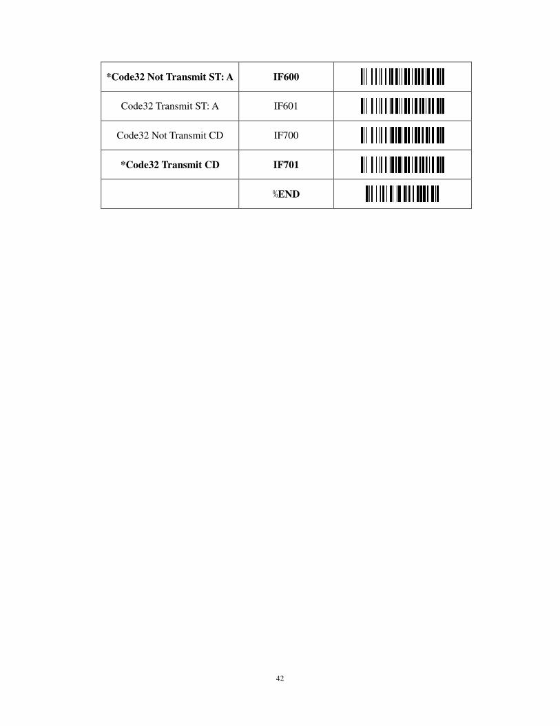
*Code32 Not Transmit ST: A IF600
Code32 Transmit ST: A IF601
Code32 Not Transmit CD IF700
*Code32 Transmit CD IF701
%END
43
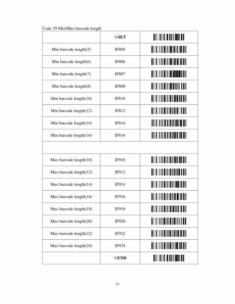
Code 39 Min/Max barcode length
%SET
Min barcode length(5) IF805
Min barcode length(6) IF806
Min barcode length(7) IF807
Min barcode length(8) IF808
Min barcode length(10) IF810
Min barcode length(12) IF812
Min barcode length(14) IF814
Min barcode length(16) IF816
Max barcode length(10) IF910
Max barcode length(12) IF912
Max barcode length(14) IF914
Max barcode length(16) IF916
Max barcode length(18) IF918
Max barcode length(20) IF920
Max barcode length(22) IF922
Max barcode length(24) IF924
%END
44
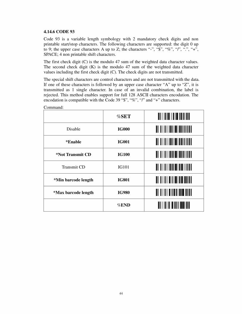
4.14.6 CODE 93
Code 93 is a variable length symbology with 2 mandatory check digits and non printable start/stop characters. The following characters are supported: the digit 0 up to 9; the upper case characters A up to Z; the characters “-”, “$”, “%”, “/”, “.”, “+”, SPACE; 4 non printable shift characters.
The first check digit (C) is the modulo 47 sum of the weighted data character values. The second check digit (K) is the modulo 47 sum of the weighted data character values including the first check digit (C). The check digits are not transmitted.
The special shift characters are control characters and are not transmitted with the data. If one of these characters is followed by an upper case character “A” up to “Z”, it is transmitted as 1 single character. In case of an invalid combination, the label is rejected. This method enables support for full 128 ASCII characters encodation. The encodation is compatible with the Code 39 “$”, “%”, “/” and “+” characters.
Command:
%SET
Disable IG000
*Enable IG001
*Not Transmit CD IG100
Transmit CD IG101
*Min barcode length IG801
*Max barcode length IG980
%END

45
Code 93 Min/Max barcode length
%SET
Min barcode length(2) IG802
Min barcode length(4) IG804
Min barcode length(6) IG806
Min barcode length(8) IG808
Min barcode length(10) IG810
Min barcode length(12) IG812
Min barcode length(14) IG814
Min barcode length(16) IG816
Max barcode length(10) IG910
Max barcode length(12) IG912
Max barcode length(14) IG914
Max barcode length(16) IG916
Max barcode length(18) IG918
Max barcode length(20) IG920
Max barcode length(22) IG922
Max barcode length(24) IG924
%END

46
4.14.7 INTERLEAVED 2 OF 5
This symbology encodes a pair of digits in each symbol. The number of digits is therefore always an even number. Information is carried in the bars and spaces. The start and stop pattern are not unique inside the code. It is therefore essential to use the fixed length option to prevent partial reads.
Command:
%SET
Disable IH000
*Enable IH001
*Not Check CD IH100
Check CD IH101
Not Transmit CD IH200
*Transmit CD IH201
*Min barcode length IH804
*Max barcode length IH970
%END
47
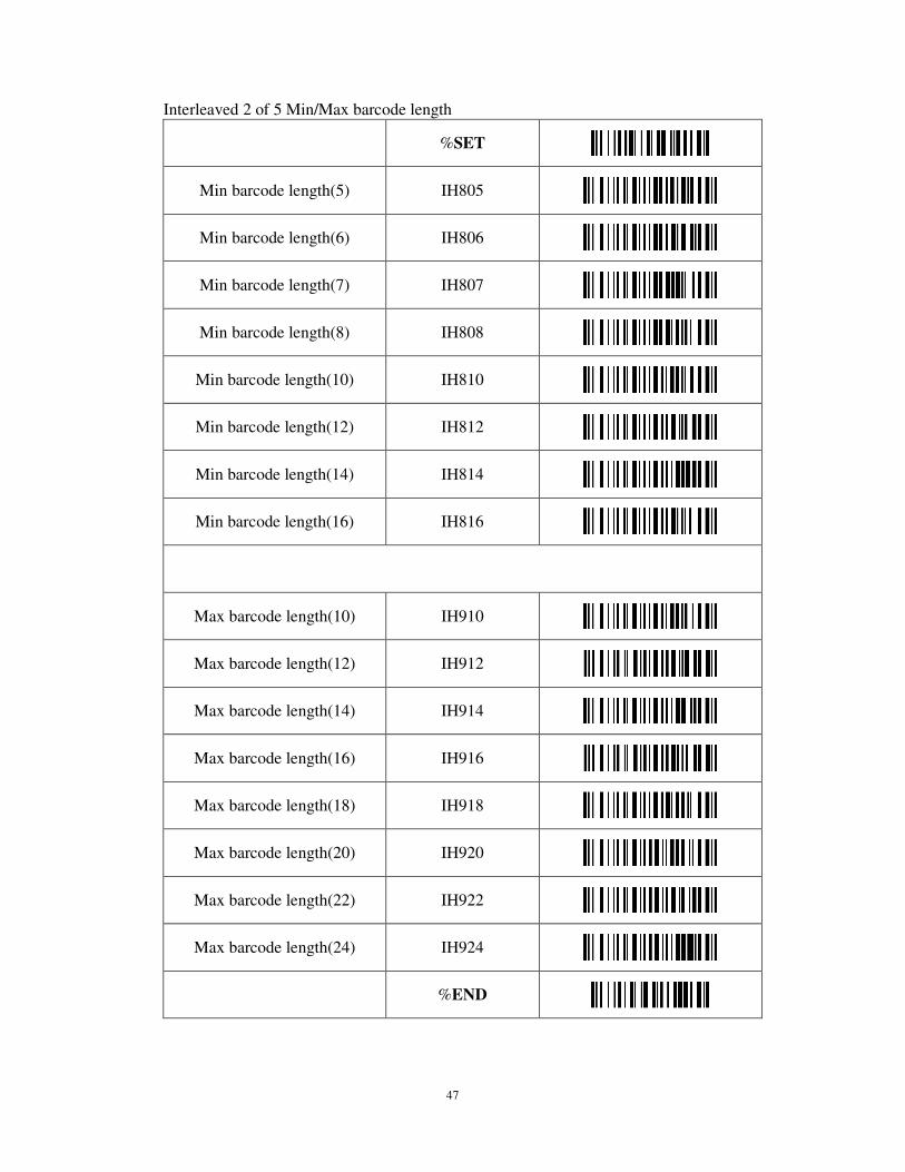
Interleaved 2 of 5 Min/Max barcode length
%SET
Min barcode length(5) IH805
Min barcode length(6) IH806
Min barcode length(7) IH807
Min barcode length(8) IH808
Min barcode length(10) IH810
Min barcode length(12) IH812
Min barcode length(14) IH814
Min barcode length(16) IH816
Max barcode length(10) IH910
Max barcode length(12) IH912
Max barcode length(14) IH914
Max barcode length(16) IH916
Max barcode length(18) IH918
Max barcode length(20) IH920
Max barcode length(22) IH922
Max barcode length(24) IH924
%END
48
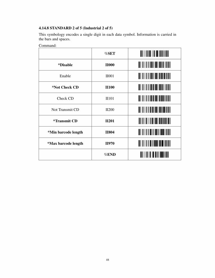
4.14.8 STANDARD 2 of 5 (Industrial 2 of 5)
This symbology encodes a single digit in each data symbol. Information is carried in the bars and spaces.
Command:
%SET
*Disable II000
Enable II001
*Not Check CD II100
Check CD II101
Not Transmit CD II200
*Transmit CD II201
*Min barcode length II804
*Max barcode length II970
%END
49
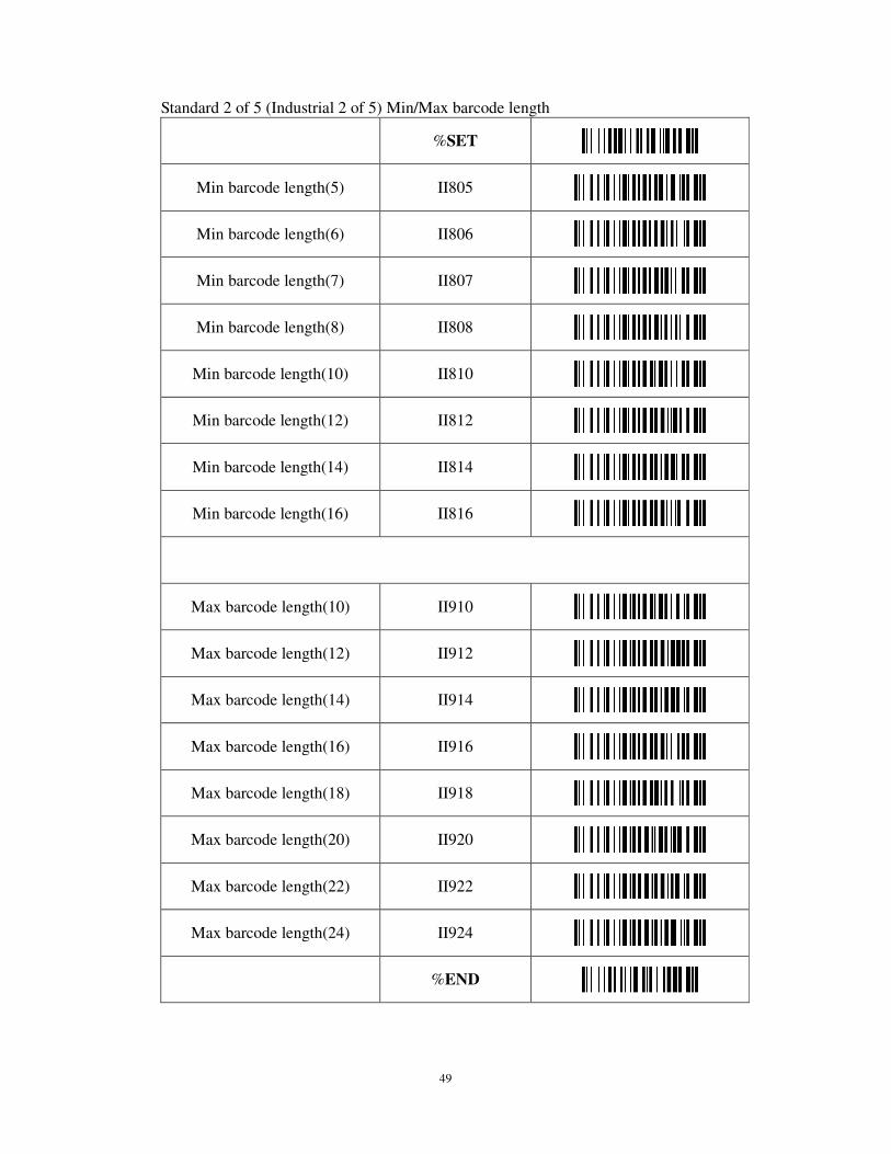
Standard 2 of 5 (Industrial 2 of 5) Min/Max barcode length
%SET
Min barcode length(5) II805
Min barcode length(6) II806
Min barcode length(7) II807
Min barcode length(8) II808
Min barcode length(10) II810
Min barcode length(12) II812
Min barcode length(14) II814
Min barcode length(16) II816
Max barcode length(10) II910
Max barcode length(12) II912
Max barcode length(14) II914
Max barcode length(16) II916
Max barcode length(18) II918
Max barcode length(20) II920
Max barcode length(22) II922
Max barcode length(24) II924
%END
50
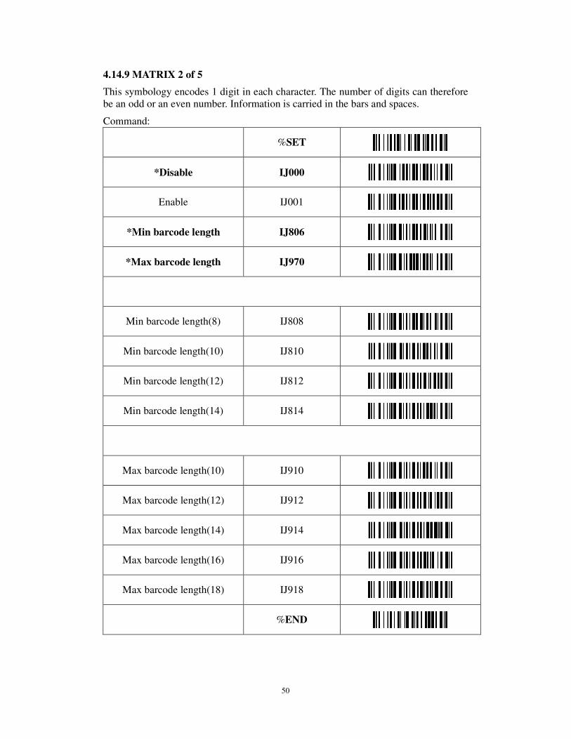
4.14.9 MATRIX 2 of 5
This symbology encodes 1 digit in each character. The number of digits can therefore be an odd or an even number. Information is carried in the bars and spaces.
Command:
%SET
*Disable IJ000
Enable IJ001
*Min barcode length IJ806
*Max barcode length IJ970
Min barcode length(8) IJ808
Min barcode length(10) IJ810
Min barcode length(12) IJ812
Min barcode length(14) IJ814
Max barcode length(10) IJ910
Max barcode length(12) IJ912
Max barcode length(14) IJ914
Max barcode length(16) IJ916
Max barcode length(18) IJ918
%END
51
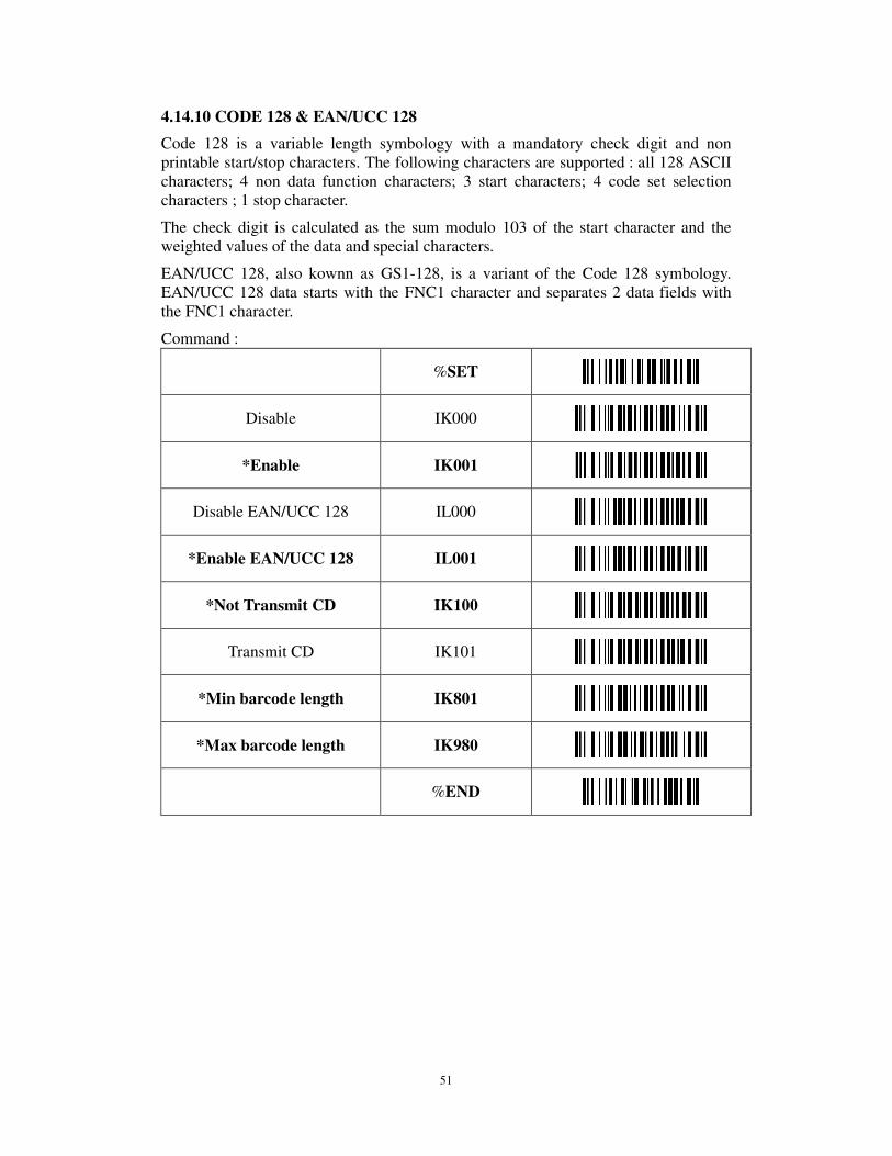
4.14.10 CODE 128 & EAN/UCC 128
Code 128 is a variable length symbology with a mandatory check digit and non printable start/stop characters. The following characters are supported : all 128 ASCII characters; 4 non data function characters; 3 start characters; 4 code set selection characters ; 1 stop character.
The check digit is calculated as the sum modulo 103 of the start character and the weighted values of the data and special characters.
EAN/UCC 128, also kownn as GS1-128, is a variant of the Code 128 symbology. EAN/UCC 128 data starts with the FNC1 character and separates 2 data fields with the FNC1 character.
Command :
%SET
Disable IK000
*Enable IK001
Disable EAN/UCC 128 IL000
*Enable EAN/UCC 128 IL001
*Not Transmit CD IK100
Transmit CD IK101
*Min barcode length IK801
*Max barcode length IK980
%END

52
Code 128 & EAN/UCC128 Min/Max barcode length
%SET
Min barcode length(4) IK804
Min barcode length(6) IK806
Min barcode length(7) IK807
Min barcode length(8) IK808
Min barcode length(10) IK810
Min barcode length(12) IK812
Min barcode length(14) IK814
Min barcode length(16) IK816
Max barcode length(10) IK910
Max barcode length(12) IK912
Max barcode length(14) IK914
Max barcode length(16) IK916
Max barcode length(18) IK918
Max barcode length(20) IK920
Max barcode length(22) IK922
Max barcode length(24) IK924
%END
53
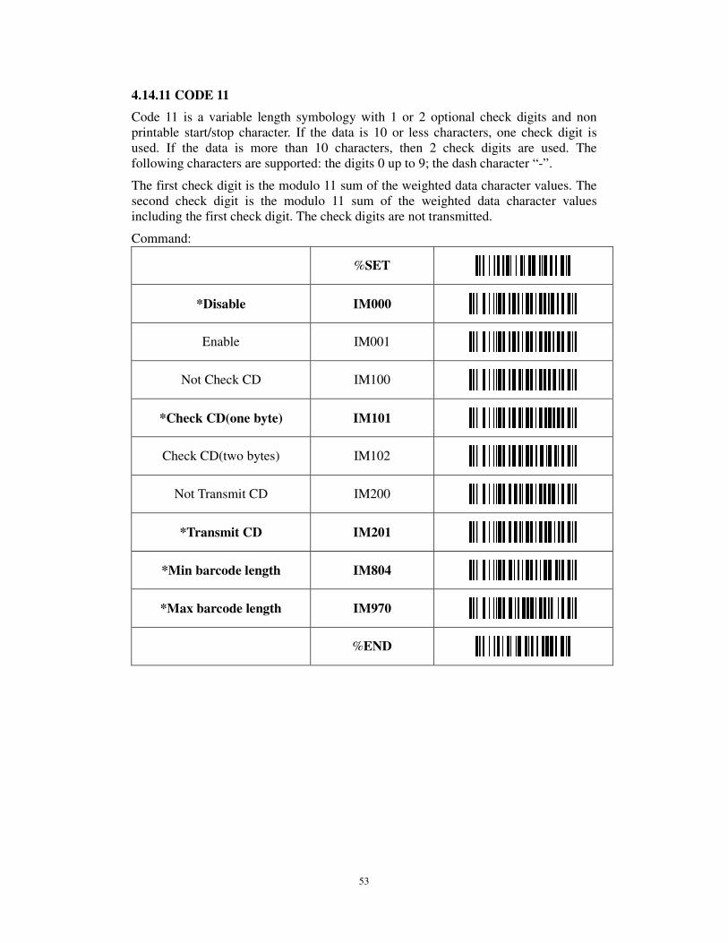
4.14.11 CODE 11
Code 11 is a variable length symbology with 1 or 2 optional check digits and non printable start/stop character. If the data is 10 or less characters, one check digit is used. If the data is more than 10 characters, then 2 check digits are used. The following characters are supported: the digits 0 up to 9; the dash character “-”.
The first check digit is the modulo 11 sum of the weighted data character values. The second check digit is the modulo 11 sum of the weighted data character values including the first check digit. The check digits are not transmitted.
Command:
%SET
*Disable IM000
Enable IM001
Not Check CD IM100
*Check CD(one byte) IM101
Check CD(two bytes) IM102
Not Transmit CD IM200
*Transmit CD IM201
*Min barcode length IM804
*Max barcode length IM970
%END
54
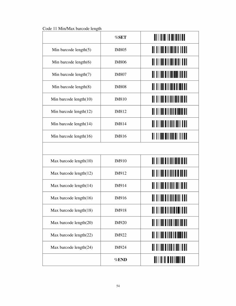
Code 11 Min/Max barcode length
%SET
Min barcode length(5) IM805
Min barcode length(6) IM806
Min barcode length(7) IM807
Min barcode length(8) IM808
Min barcode length(10) IM810
Min barcode length(12) IM812
Min barcode length(14) IM814
Min barcode length(16) IM816
Max barcode length(10) IM910
Max barcode length(12) IM912
Max barcode length(14) IM914
Max barcode length(16) IM916
Max barcode length(18) IM918
Max barcode length(20) IM920
Max barcode length(22) IM922
Max barcode length(24) IM924
%END
55
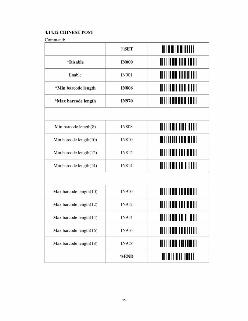
4.14.12 CHINESE POST
Command:
%SET
*Disable IN000
Enable IN001
*Min barcode length IN806
*Max barcode length IN970
Min barcode length(8) IN808
Min barcode length(10) IN810
Min barcode length(12) IN812
Min barcode length(14) IN814
Max barcode length(10) IN910
Max barcode length(12) IN912
Max barcode length(14) IN914
Max barcode length(16) IN916
Max barcode length(18) IN918
%END
56
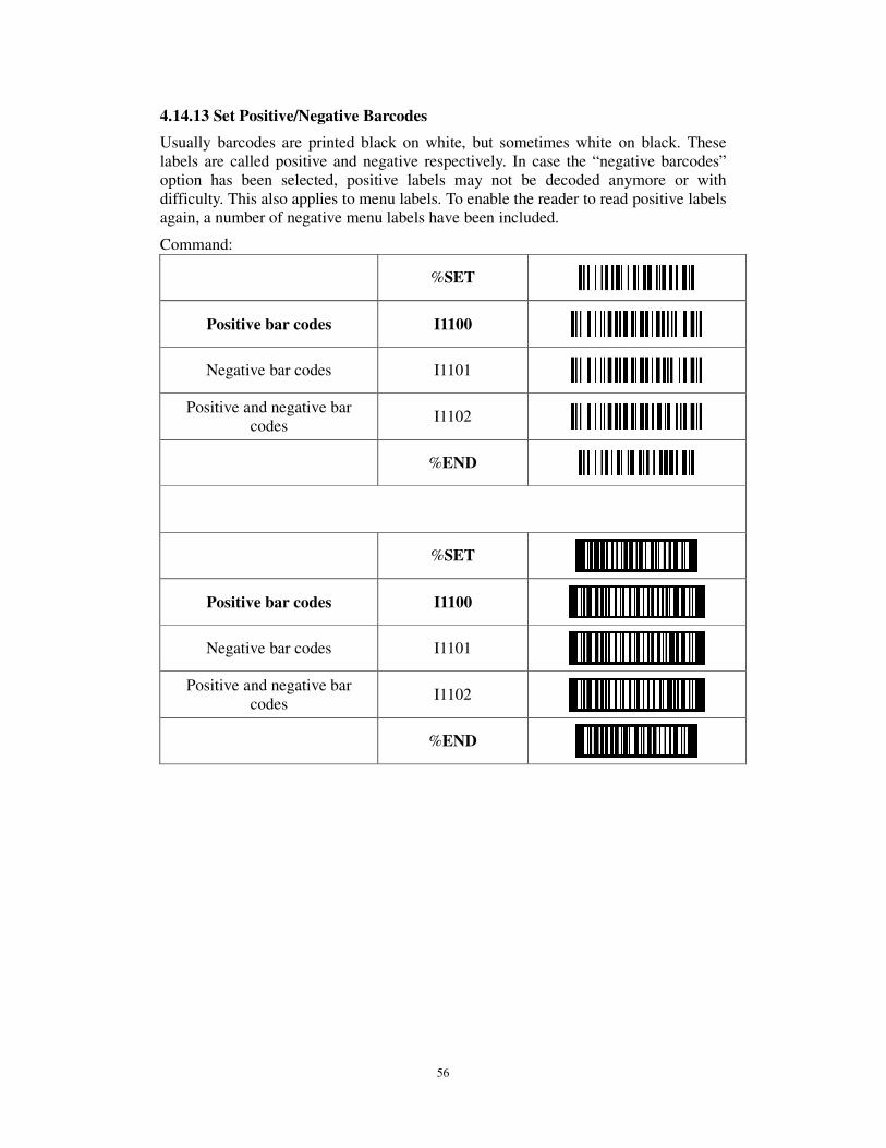
4.14.13 Set Positive/Negative Barcodes
Usually barcodes are printed black on white, but sometimes white on black. These labels are called positive and negative respectively. In case the “negative barcodes” option has been selected, positive labels may not be decoded anymore or with difficulty. This also applies to menu labels. To enable the reader to read positive labels again, a number of negative menu labels have been included.
Command:
%SET
Positive bar codes I1100
Negative bar codes I1101
Positive and negative bar codes
I1102
%END
%SET
Positive bar codes I1100
Negative bar codes I1101
Positive and negative bar codes
I1102
%END
57
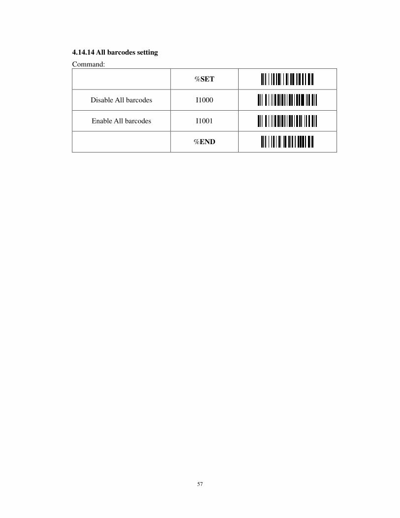
4.14.14 All barcodes setting
Command:
%SET
Disable All barcodes I1000
Enable All barcodes I1001
%END
58
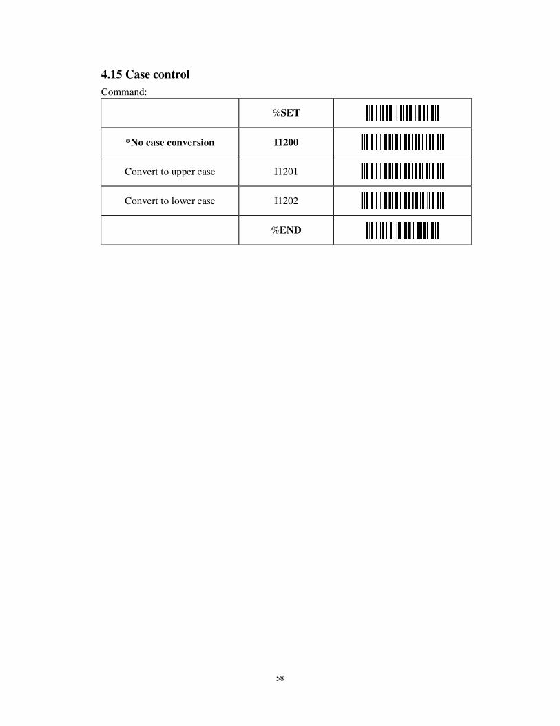
4.15 Case control
Command:
%SET
*No case conversion I1200
Convert to upper case I1201
Convert to lower case I1202
%END
59
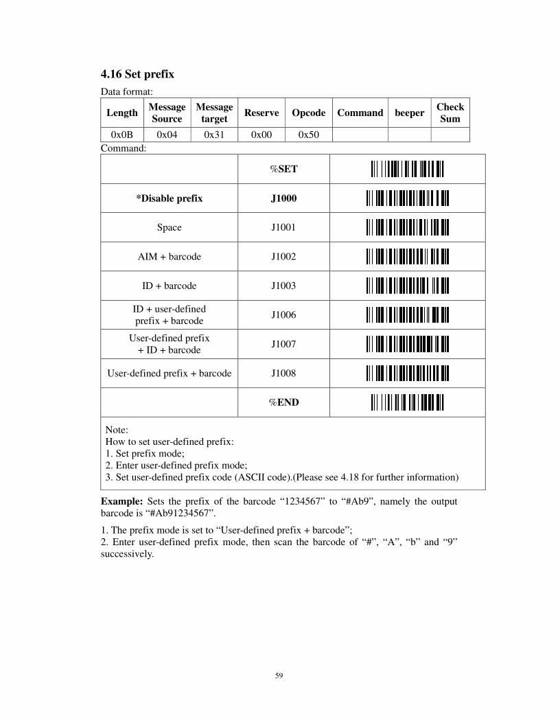
4.16 Set prefix
Data format:
Length Message Source
Message target
Reserve Opcode Command beeper Check Sum
0x0B 0x04 0x31 0x00 0x50
Command:
%SET
*Disable prefix J1000
Space J1001
AIM + barcode J1002
ID + barcode J1003
ID + user-defined prefix + barcode
J1006
User-defined prefix + ID + barcode
J1007
User-defined prefix + barcode J1008
%END
Note: How to set user-defined prefix: 1. Set prefix mode; 2. Enter user-defined prefix mode; 3. Set user-defined prefix code (ASCII code).(Please see 4.18 for further information)
Example: Sets the prefix of the barcode “1234567” to “#Ab9”, namely the output barcode is “#Ab91234567”.
1. The prefix mode is set to “User-defined prefix + barcode”; 2. Enter user-defined prefix mode, then scan the barcode of “#”, “A”, “b” and “9” successively.
60
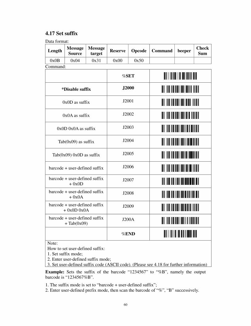
4.17 Set suffix
Data format:
Length Message Source
Message target
Reserve Opcode Command beeper Check Sum
0x0B 0x04 0x31 0x00 0x50
Command:
%SET
*Disable suffix J2000
0x0D as suffix J2001
0x0A as suffix J2002
0x0D 0x0A as suffix J2003
Tab(0x09) as suffix J2004
Tab(0x09) 0x0D as suffix J2005
barcode + user-defined suffix J2006
barcode + user-defined suffix + 0x0D
J2007
barcode + user-defined suffix + 0x0A
J2008
barcode + user-defined suffix + 0x0D 0x0A
J2009
barcode + user-defined suffix + Tab(0x09)
J200A
%END
Note: How to set user-defined suffix: 1. Set suffix mode; 2. Enter user-defined suffix mode; 3. Set user-defined suffix code (ASCII code). (Please see 4.18 for further information)
Example: Sets the suffix of the barcode “1234567” to “%B”, namely the output barcode is “1234567%B”.
1. The suffix mode is set to “barcode + user-defined suffix”; 2. Enter user-defined prefix mode, then scan the barcode of “%”, “B” successively.

61
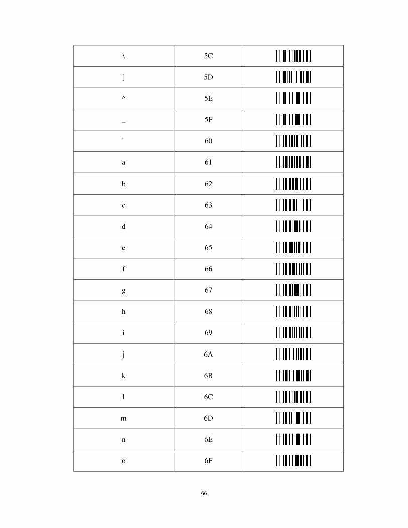
4.18 Customize prefix/suffix
Command:
%SET
Enter user-defined prefix mode
JA100
Enter user-defined suffix mode
JA200
Control character Hex
^@ (NULL) 00
^A (SOH) 01
^B (STX) 02
^C (ETX) 03
^D (EOT) 04
^E (ENQ) 05
^F (ACK) 06
^G (BEL) 07
^H (BS) 08
^I (HT) 09
^J (LF) 0A
^K (VT) 0B
^L (FF) 0C
^M (CR) 0D

62
^N (SO) 0E
^O (SI) 0F
^P (DLE) 10
^Q (DC1) 11
^R (DC2) 12
^S (DC3) 13
^T (DC4) 14
^U (NAK) 15
^V (SYN) 16
^W (ETB) 17
^X (CAN) 18
^Y (EM) 19
^Z (SUB) 1A
^[ (ESC) 1B
^\ (FS) 1C
^] (GS) 1D
^^ (RS) 1E
^_ (US) 1F
SPC 20

63
Character Hex
! 21
" 22
# 23
$ 24
% 25
& 26
' 27
( 28
) 29
* 2A
+ 2B
, 2C
- 2D
. 2E
/ 2F
0 30
1 31
2 32
3 33

64
4 34
5 35
6 36
7 37
8 38
9 39
: 3A
; 3B
< 3C
= 3D
> 3E
? 3F
@ 40
A 41
B 42
C 43
D 44
E 45
F 46
G 47

65
H 48
I 49
J 4A
K 4B
L 4C
M 4D
N 4E
O 4F
P 50
Q 51
R 52
S 53
T 54
U 55
V 56
W 57
X 58
Y 59
Z 5A
[ 5B
66
\ 5C
] 5D
^ 5E
_ 5F
` 60
a 61
b 62
c 63
d 64
e 65
f 66
g 67
h 68
i 69
j 6A
k 6B
l 6C
m 6D
n 6E
o 6F
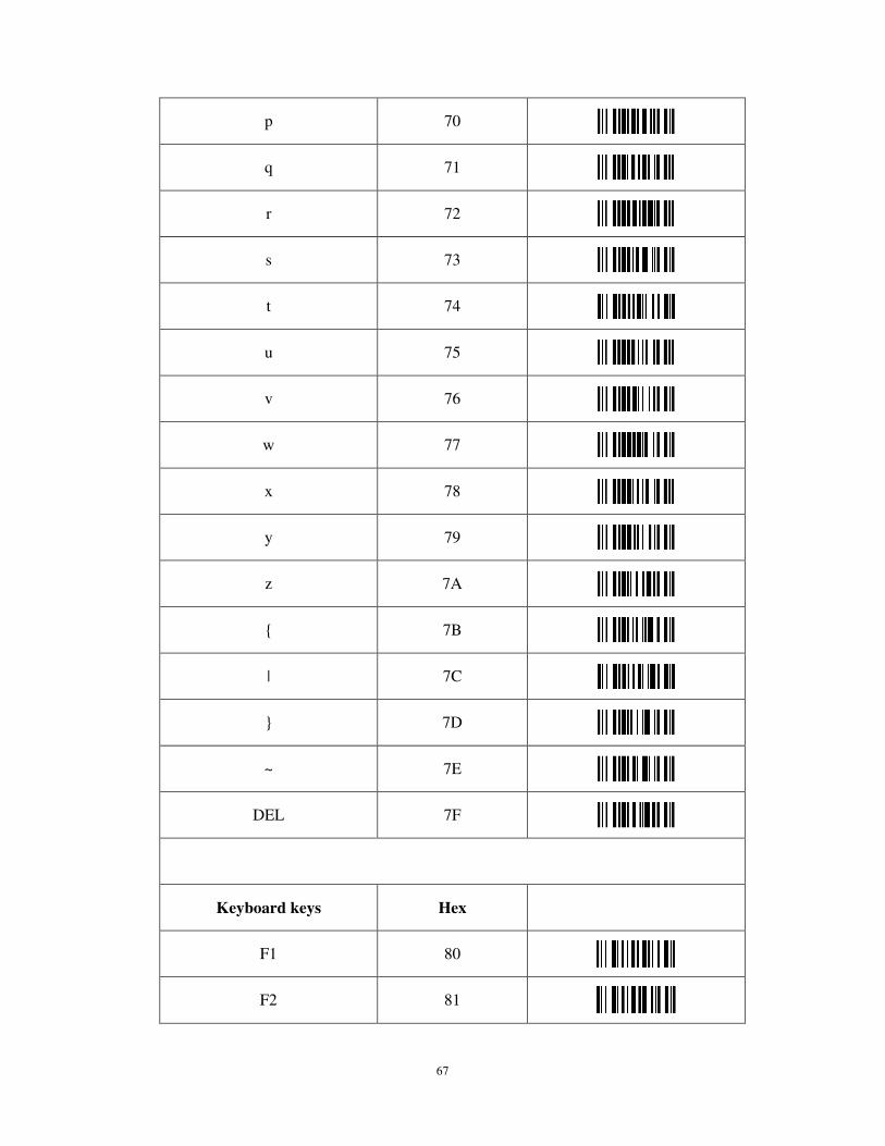
67
p 70
q 71
r 72
s 73
t 74
u 75
v 76
w 77
x 78
y 79
z 7A
{ 7B
| 7C
} 7D
~ 7E
DEL 7F
Keyboard keys Hex
F1 80
F2 81
68
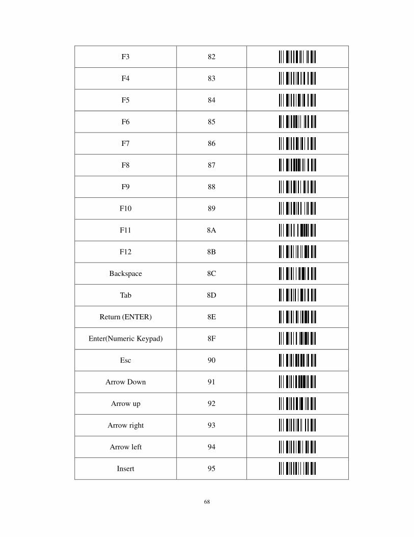
F3 82
F4 83
F5 84
F6 85
F7 86
F8 87
F9 88
F10 89
F11 8A
F12 8B
Backspace 8C
Tab 8D
Return (ENTER) 8E
Enter(Numeric Keypad) 8F
Esc 90
Arrow Down 91
Arrow up 92
Arrow right 93
Arrow left 94
Insert 95
69
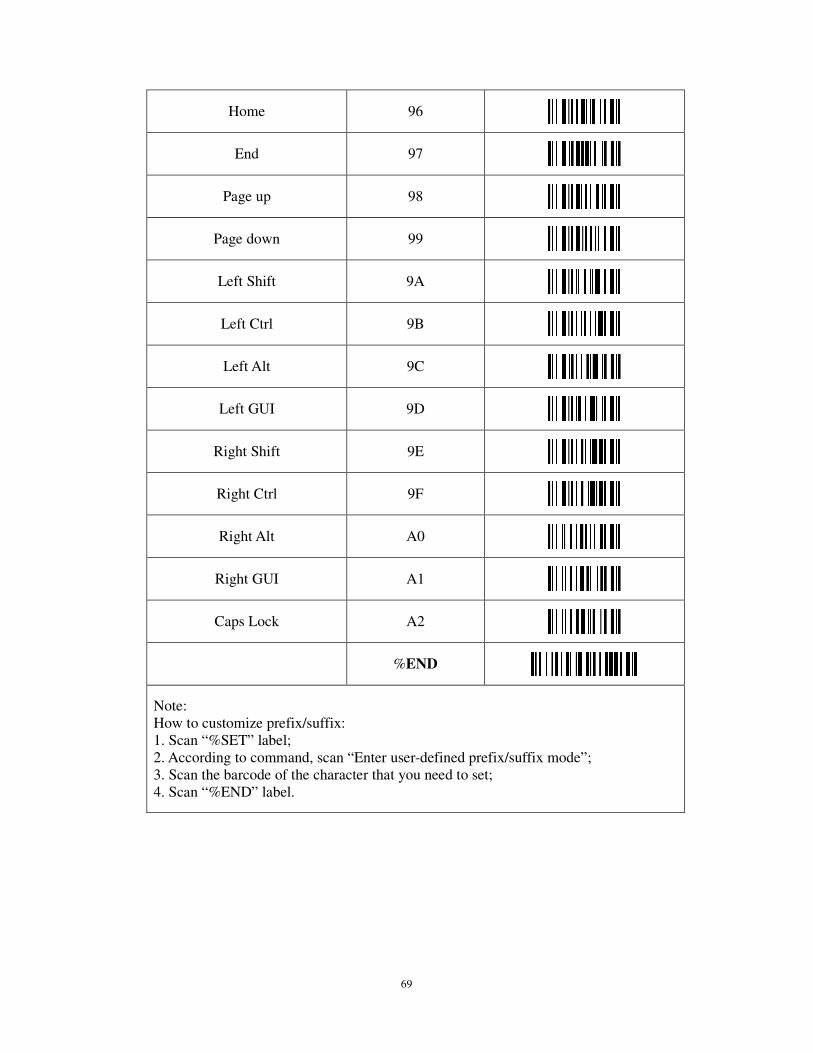
Home 96
End 97
Page up 98
Page down 99
Left Shift 9A
Left Ctrl 9B
Left Alt 9C
Left GUI 9D
Right Shift 9E
Right Ctrl 9F
Right Alt A0
Right GUI A1
Caps Lock A2
%END
Note: How to customize prefix/suffix: 1. Scan “%SET” label; 2. According to command, scan “Enter user-defined prefix/suffix mode”; 3. Scan the barcode of the character that you need to set; 4. Scan “%END” label.

70
4.19 Update firmware mode
Command:
%SET
Update firmware mode $down
%END
Note: 1. This feature only supports USB interface. When you don’t need to update the firmware, please use caution. 2. When switching to update firmware mode and then repowering the product, it will automatically virtualize the USB keyboard wedge to serial port and allow to update the product’s firmware.When the update is complete, it will automatically switch to normal mode. If you give up updating the firmware, you can restore the factory default or reset the interface and also can switch to the normal mode.

71
Appendixes
Appendix 1: Barcode test card
72
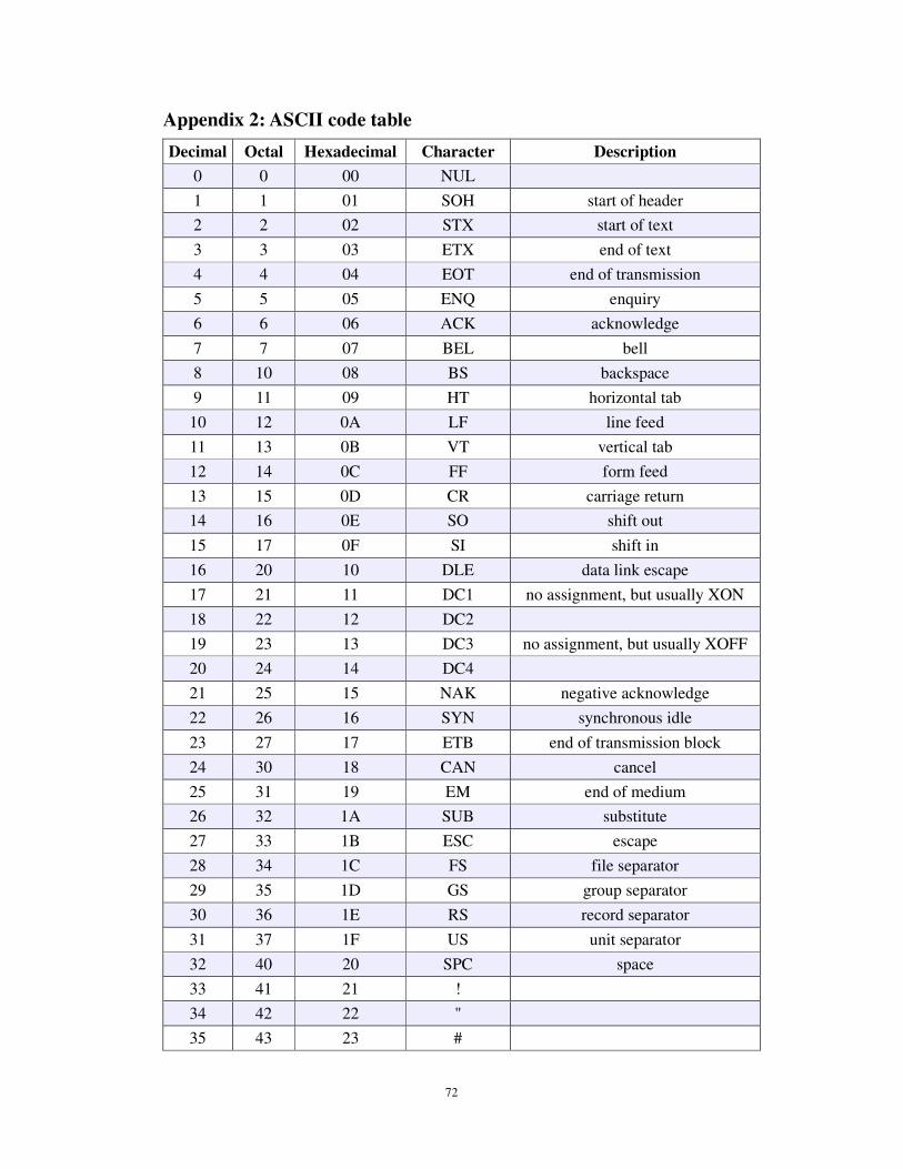
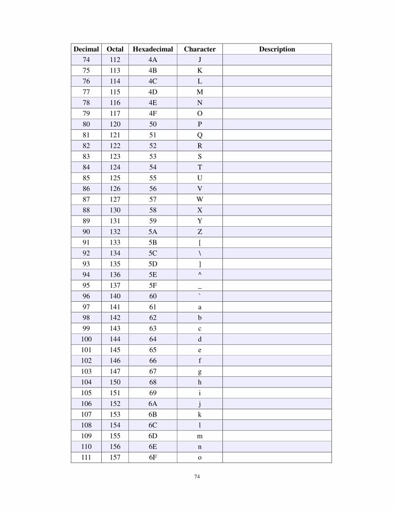
Appendix 2: ASCII code table
Decimal Octal Hexadecimal Character Description
0 0 00 NUL
1 1 01 SOH start of header
2 2 02 STX start of text
3 3 03 ETX end of text
4 4 04 EOT end of transmission
5 5 05 ENQ enquiry
6 6 06 ACK acknowledge
7 7 07 BEL bell
8 10 08 BS backspace
9 11 09 HT horizontal tab
10 12 0A LF line feed
11 13 0B VT vertical tab
12 14 0C FF form feed
13 15 0D CR carriage return
14 16 0E SO shift out
15 17 0F SI shift in
16 20 10 DLE data link escape
17 21 11 DC1 no assignment, but usually XON
18 22 12 DC2
19 23 13 DC3 no assignment, but usually XOFF
20 24 14 DC4
21 25 15 NAK negative acknowledge
22 26 16 SYN synchronous idle
23 27 17 ETB end of transmission block
24 30 18 CAN cancel
25 31 19 EM end of medium
26 32 1A SUB substitute
27 33 1B ESC escape
28 34 1C FS file separator
29 35 1D GS group separator
30 36 1E RS record separator
31 37 1F US unit separator
32 40 20 SPC space
33 41 21 !
34 42 22 "
35 43 23 #
73
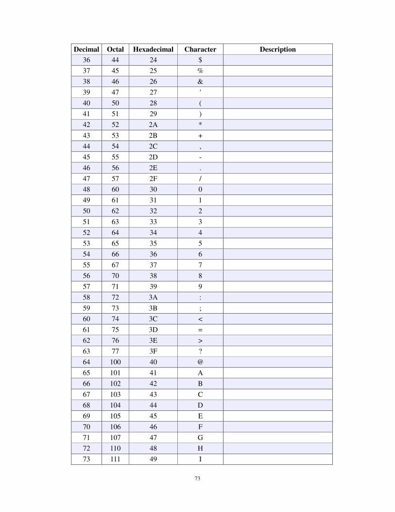
Decimal Octal Hexadecimal Character Description
36 44 24 $
37 45 25 %
38 46 26 &
39 47 27 '
40 50 28 (
41 51 29 )
42 52 2A *
43 53 2B +
44 54 2C ,
45 55 2D -
46 56 2E .
47 57 2F /
48 60 30 0
49 61 31 1
50 62 32 2
51 63 33 3
52 64 34 4
53 65 35 5
54 66 36 6
55 67 37 7
56 70 38 8
57 71 39 9
58 72 3A :
59 73 3B ;
60 74 3C <
61 75 3D =
62 76 3E >
63 77 3F ?
64 100 40 @
65 101 41 A
66 102 42 B
67 103 43 C
68 104 44 D
69 105 45 E
70 106 46 F
71 107 47 G
72 110 48 H
73 111 49 I
74
Decimal Octal Hexadecimal Character Description
74 112 4A J
75 113 4B K
76 114 4C L
77 115 4D M
78 116 4E N
79 117 4F O
80 120 50 P
81 121 51 Q
82 122 52 R
83 123 53 S
84 124 54 T
85 125 55 U
86 126 56 V
87 127 57 W
88 130 58 X
89 131 59 Y
90 132 5A Z
91 133 5B [
92 134 5C \
93 135 5D ]
94 136 5E ^
95 137 5F _
96 140 60 `
97 141 61 a
98 142 62 b
99 143 63 c
100 144 64 d
101 145 65 e
102 146 66 f
103 147 67 g
104 150 68 h
105 151 69 i
106 152 6A j
107 153 6B k
108 154 6C l
109 155 6D m
110 156 6E n
111 157 6F o
75
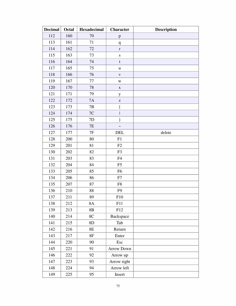
Decimal Octal Hexadecimal Character Description
112 160 70 p
113 161 71 q
114 162 72 r
115 163 73 s
116 164 74 t
117 165 75 u
118 166 76 v
119 167 77 w
120 170 78 x
121 171 79 y
122 172 7A z
123 173 7B {
124 174 7C |
125 175 7D }
126 176 7E ~
127 177 7F DEL delete
128 200 80 F1
129 201 81 F2
130 202 82 F3
131 203 83 F4
132 204 84 F5
133 205 85 F6
134 206 86 F7
135 207 87 F8
136 210 88 F9
137 211 89 F10
138 212 8A F11
139 213 8B F12
140 214 8C Backspace
141 215 8D Tab
142 216 8E Return
143 217 8F Enter
144 220 90 Esc
145 221 91 Arrow Down
146 222 92 Arrow up
147 223 93 Arrow right
148 224 94 Arrow left
149 225 95 Insert

76
Decimal Octal Hexadecimal Character Description
150 226 96 Home
151 227 97 End
152 230 98 Page up
153 231 99 Page down
154 232 9A Left Shift
155 233 9B Left Ctrl
156 234 9C Left Alt
157 235 9D Left GUI
158 236 9E Right Shift
159 237 9F Right Ctrl
160 240 A0 Right Alt
161 241 A1 A
Right GUI
162 242 A2 Caps Lock
77
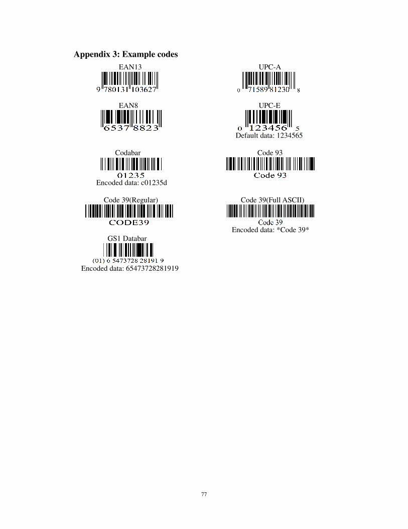
Appendix 3: Example codes
EAN13 UPC-A
EAN8 UPC-E
Default data: 1234565
Codabar Code 93
Encoded data: c01235d
Code 39(Regular) Code 39(Full ASCII)
Encoded data: *Code 39*
GS1 Databar
Encoded data: 65473728281919