specification of cortex board - lcdtek.co.uk · mipi1 mipi dsi interface aj752-b-s-51_b edp 1 0.5mm...
TRANSCRIPT

DDaattaa SShheeeett
~ 1 ~
Specification of Cortex Board (LVDS, HDMI, eDP , MIPI supportable)
Model Name : Orion RK3288 Part No. : ORN–3288– xxx….xxx
(xxx...xxx : mating LCD part number)
June 2016

DDaattaa SShheeeett
~ 2 ~
Revision History
PCB Version Rev. date Revision Details
0.0 Nov. 2014 Initial Version issue
0.0 Dec. 2014 CON3 Pin Map Update
1.0 May. 2015 Update about the supportability of 4k-2k through the HDMI output
1.0 July. 2015 Addition of some Connectors' name & Role Assignment
2.0 Aug. 2015
-. Change the mounting holes : from 1.9 Ø x 5 numbers to 3.4 Ø x 4 numbers -. Removal of Optical Audio Port on the PCB Refer to the Appendix from page 15 to page 18
2.0 June. 2016 Addition of all Connectors' name & Role Assignment 2.0 Jan. 2017 Update Spec detail.

DDaattaa SShheeeett
~ 3 ~
Contents
1 Spec Summary ------------------------------------------ 4
2 General Description ----------------------------------- 5 3 RK3288 Block Diagram ------------------------------- 6
4 Dimension ------------------------------------------------- 7
5 Pictures ---------------------------------------------------- 8
6 Connectors and Pin information -------------------- 9 ~15 Appendix A. ---------------------------------------------------- 16~19
The information presented in this document may form a part of quotation or contract under the agreement of both parties. Otherwise, this datasheet is subject to change without notice.

DDaattaa SShheeeett
~ 4 ~
1. Spec Summary
l RockChip RK3288 Quadcore l 2GByte DDR3 Memory ( Optional upto 4GByte) l 16GByte eMMC Memory l Dual-channels TFT LCD interface with 4-layers, 3840x2160 maximum display size. l 1CH/2CH LVDS Interface for LCD – 6bits, 8 bits, 10bits l 1lane/2lane/4lane eDP interface for LCD – 1.62Gbps/2.7Gbps l HDMI v2.0 Support (4K2K support) l MIPI DSI Interface l 3-Port USB – external 2port / internal 1port l IEEE802.3 10/100/1000Mbps with Twisted-Pare l IEEE802.11b/g/n WIFI with Bluetooth 4.0(Optional IEEE802.11a/b/g/n/ac) l MicroSD/SDHC 1 Slot(Max. 32GByte) l RS-232C : external 1Port l UART : internal 1port l External Speaker : 2W + 2W (8Ω), 2.9W + 2.9W(4Ω) l Headset interface port(stereo headphone with MIC) l 3G/4G modem interface with daughter board(optional) l MicroUSB OTG 1port l Camera Interface : 2port – MIPI CSI, 12bits CCIR Camera I/F(CIF) l Keypad Interface : ESC, Volume+/-, PowerOn(Option board) l IR Remote control interface l Form factor: 150 x 110 x 20 mm l I2C Interface for Touch(Option) l Operating temperature: 0 to 50 l Power: 12V DC Power adaptor, SMPS (Optional select)

DDaattaa SShheeeett
~ 5 ~
2. General Description RK3288 is a low power, high performance processor for mobile phones, personal mobile internet device and other digital multimedia applications, and integrates quad-core Cortex-A17 with separately NEON and FPU coprocessor. Many embedded powerful hardware engines provide optimized performance for high-end application. RK3288 supports almost full-format; include H.265 decoder by 2160p@60fps, H.264 decoder by 2160p@24fps, also support H.264/MVC/VP8 encoder by 1080p@30fps, high-quality JPEG encoder/decoder, and special image preprocessor and postprocessor. Embedded 3D GPU makes RK3288 completely compatible with OpenGL ES1.1/2.0/3.0, OpenCL 1.1 and DirectX 11. Special 2D hardware engine with MMU will maximize display performance and provide very smoothly operation. RK3288 has high-performance dual channel external memory interface (DDR3/DDR3L /LPDDR2/LPDDR3) capable of sustaining demanding memory bandwidth, also provides a complete set of peripheral interface to support very flexible applications. The HDMI quality of this ARM board is real FHD resolution at the true color 30 bit(RGBx10bits) setting [ Special Note ] : the reserved firmware status for the GUI / Graphic User Interface -. the first Product Group : for the users of " Digital Signage Monitor " the adoption of " Android " : version 4.4.4 so called " KitKat " Linux Kernel Version : 3.10.49 the adoption of " Android " : version 5.1.x so called " Lollipop " Linux Kernel Version : 3.10.79 the adoption of " Android " : version 6.0.x so called " Marshmallow " under development Linux Kernel Version : 3.10.92 -. the second Product Group : for the users of " Industrial ARM based Monitor " the adoption of " Ubuntu " : version 14.04 so called "LXDE" Linaro Image Linux Kernel Version : 3.10.49 The default type of product is Android 4.4.4 KitKat, so if any user need to adopt others such as Android 5.1.x Lollipop or Uubuntu 14.04 LXDE, the customers are requested to instruct the demand on the order sheet correctly.

DDaattaa SShheeeett
~ 6 ~
3. RK3288 Block Diagram
DDaattaa SShheeeett
~ 7 ~
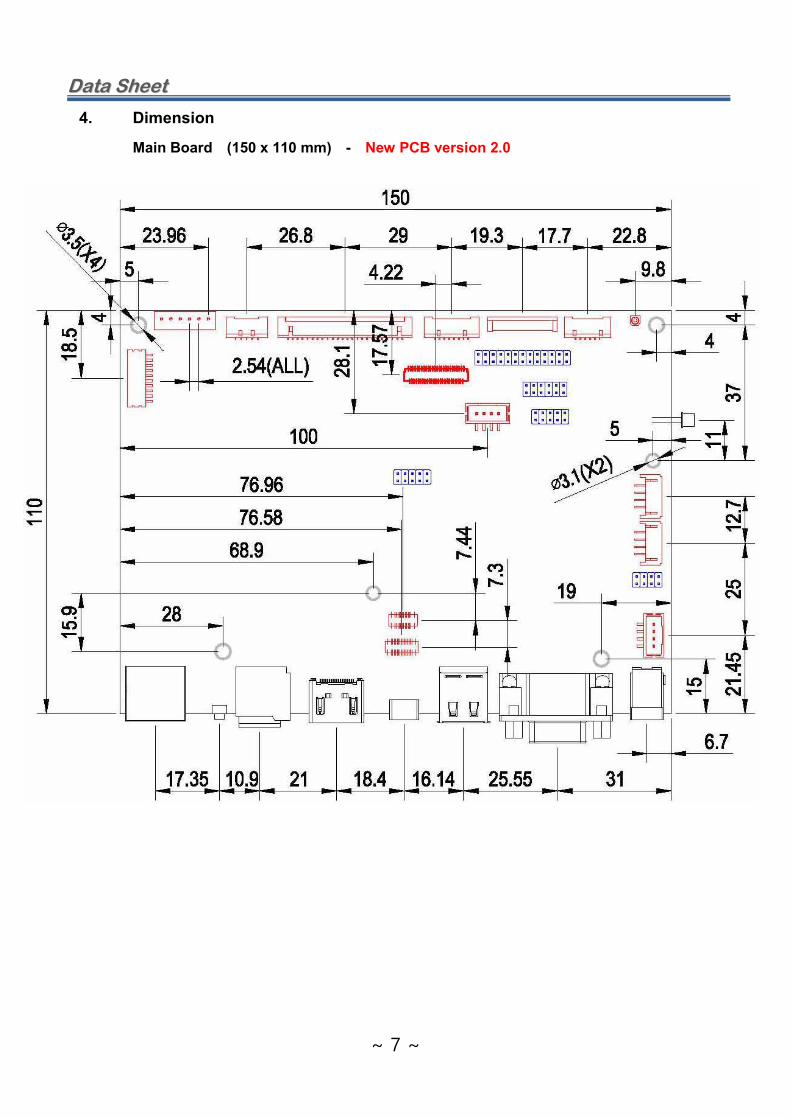
4. Dimension Main Board (150 x 110 mm) - New PCB version 2.0

DDaattaa SShheeeett
~ 8 ~
5. Pictures : New PCB version 2.0 Top Side View

DDaattaa SShheeeett
~ 9 ~
Rear Side View

DDaattaa SShheeeett
~ 10 ~
6. Connectors and Pin information 6.1 Connectors Summary
Connector No Description Type Manufacturer CON1 Headset Output DF14-5P-1.25H Hirose CON2 Speaker Output S4B-PH-SM4-TB(LF)(SN) JST CON3 Touch Screen Interface DF14-6P-1.25H Hirose CON5 Panel Extra Power DF14-5P-1.25H Hirose CON6 Extra LVDS pair for 10-bit DF14-8P-1.25H Hirose CON7 Dual LVDS DF14-25P-1.25H Hirose CON8 Backlight Power Supply DF13-10P-1.25H Hirose
J1 Micro USB HUM011D-5-S J2 Micro SDHC J3 HIDMI Output 51L019S-333N J4 Front Camera AXT624124 Female J5 DC Power In DC-005(3.5PAI) J6 GPIO - Optional I/O 2.0mm, 2row 6p, S/T Pin Header 12 pin (Hirose) J7 D-Sub (DB9) for RS-232C DB09M-A02301 J8 3G interface - 1 2.0mm, 2row 4p, S/T Pin Header 8 pin (Hirose) J9 Rear Camera AXT630124 Female
J10 3G interface - 2 2.0mm, 2row 5p, S/T Pin Header 10 pin (Hirose) J17 Internal USB Host B4B-PH-SM4-TB JST J22 Function Keypad 2.54mm 2row 5p Pin Header 10 pin (Hirose) J26 External USB Host 2 stories, Dual USB Host J28 12V DC Extra Power Input B4B-PH-SM4-TB JP1 Ethernet Port RJ45S 100M
MIPI1 MIPI DSI Interface AJ752-B-S-51_B eDP 1 0.5mm Bottom contact FFC type 05002HR-H30J05 Yeon-Ho eDP 2 2.0mm, 2row 13p, S/T Pin Header 87331-13,HEAD 26 pin (Hirose) CN1 I/R Port (Direct Insert) 2.0mm, 1row 6p,

DDaattaa SShheeeett
~ 11 ~

DDaattaa SShheeeett
~ 12 ~
6.2 Pin Information Detail 6.2.1 CON1 : Headset Output : Mating connector - DF14-5S-1.25C Pin No. Function Pin No. Function
1 GND 4 HPO_L 2 HP Detect 5 MIC 3 HPO_R
6.2.2 CON2 : Speaker Out : Mating connector – PHR-4 Pin No. Function Pin No. Function
1 SP_RP 3 SP_LN 2 SP_RN 4 SP_LP
l 2W + 2W (8Ω), 2.9W + 2.9W(4Ω)
6.2.3 CON3 : Touch Screen Interface : Mating connector - DF14-6S-1.25C Pin No. Function Pin No. Function
1 VCC(3.3V) 4 TP_SDA 2 TP_INT 5 TP_SCL 3 TP_Reset 6 GND
6.2.4 CON5 : GPIO function and Panel Extra Power : Mating connector - DF14-5S-1.25C Pin No. Function Pin No. Function Pin No. Function
1 LVDS_OPT_0 2,3 Switched panel power 4,5 GND [Note] the pin no 1 is for GPIO, then all others are for Panel Extra Power. 6.2.5 CON6 : Extra LVDS pair for 10-bit : Mating connector - DF14-8S-1.25C Pin No Function Pin No Function Pin No Function
1 GND 4 LVDS_D9P 7 LVDS_OPT_2 2 LVDS_D4P 5 LVDS_D9N 8 LVDS_OPT_3 3 LVDS_D4N 6 LVDS_OPT_1
6.2.6 CON7 : LVDS Connector : Mating connector - DF14-25S-1.25C Pin No. Function Pin No Function
1* SVcc 14 LVDS_D0N 2* SVcc 15 LVDS_D8P 3 GND 16 LVDS_D8N 4 GND 17 LVDS_CLK1P 5 LVDS_D3P 18 LVDS_CLK1N 6 LVDS_D3N 19 LVDS_D7P 7 LVDS_CLK0P 20 LVDS_D7N 8 LVDS_CLK0N 21 LVDS_D6P 9 LVDS_D2P 22 LVDS_D6N
10 LVDS_D2N 23 LVDS_D5P 11 LVDS_D1P 24 LVDS_D5N 12 LVDS_D1N 25 Enable Backlight 13 LVDS_D0P
[Note] SVcc is the Panel Power, which can be programmable by kernel setting – +3.3V/+5V/+12V

DDaattaa SShheeeett
~ 13 ~
6.2.7 CON8 : Backlight Supply Connector : Mating connector - DF13-10S-1.25C Pin No. Function Pin No. Function
1 +12V 6 +5V 2 GND 7 +12V 3 BKLT_EN 8 +12V 4 BKLT_CTRL 9 GND 5 +5V 10 GND
6.2.8 J5 : 12V DC In : DC3-3.5 (Barrel Jack type) Pin No. Function Pin No. Function Pin No. Function
1 +12V 2 Detect 3 GND 6.2.9 J6 : Optional GPIO : 2.0mm 2x6 Header Pin No. Function Pin No Function
1 SPI_CLK 7 UART1_RX 2 SPI_CSN0 8 UART1_TX 3 SPI2_RXD 9 UART1_CTS 4 SPI2_TXD 10 UART1_RTS 5 VCC_OUT 11 I2C1_SDA 6 GND 12 I2C2_SCL
6.2.10 J7 : RS-232C (9 pin D-Sub) Pin No. Function Pin No. Function
1 NC 6 NC 2 RXD 7 RTS 3 TXD 8 CTS 4 NC 9 NC 5 GND
6.2.11 J17 Internal USB : Pin No. Function Pin No. Function Pin No. Function Pin No. Function
1 +5V 2 DM 3 DP 4 GND 6.2.12 J22 : Function Keypad : Pin No. Function Pin No. Function Pin No. Function
1 VOL+ 5 ESC 9 Ground 2 Power LED + 6 Power On Key 10 NC 3 VOL- 7 OPT 4 Power LED - 8 P KEY_V
6.2.13 J28 : wire type DC 12V Power Input connector : Pin No. Function Pin No. Function Pin No. Function Pin No. Function
1 +12V 2 +12V 3 GND 4 GND

DDaattaa SShheeeett
~ 14 ~
6.2.14 J4 : Camera Port : Front Camera – AXT624124 Female Pin No Function Pin No Function Pin No Function
1 PWDN1 9 PCLK 17 D7 2 SDA 10 D2 18 D8 3 SCL 11 D3 19 D9 4 VS 12 AFVDD 20 DVDD(1.8V) 5 HS 13 GND 21 PWDN0 6 DOVDD(1.8V) 14 D4 22 RST 7 MCLK 15 D5 23 AVDD(2.8V) 8 DGND 16 D6 24 AGND
6.2.15 J9 : Camera Port : Rear Camera – AXT630124 Female Pin No Function Pin No Function Pin No Function
1 AF-GND 11 RST 21 GND 2 AF-VDD(2.8V) 12 PWDN 22 D1P 3 DVDD(1.5V) 13 GND 23 D1N 4 DOVDD(1.8V) 14 MCLK 24 GND 5 NC 15 GND 25 CLK_P 6 AGND 16 D3P 26 CLK_N 7 AVDD(2.8V) 17 D3N 27 GND 8 DGND 18 GND 28 D0P 9 I2C-SDA 19 D2P 29 D0N
10 I2C-SCL 20 D2N 30 GND 6.2.16 3G Module Board interface – 2.0mm 2x4 pin J8 : 2.0mm 2x4 pin Pin No. Function Pin No Function
1 DC5VB 5 HSIC_STROBE 2 VCC_IO 6 HSIC_DATA 3 GND 7 HUB_RESET_N 4 GND 8 GSENSOR_INT
6.2.17 3G Module Board interface – 2.0mm 2x5 pin J10 : 2.0mm 2x5 pin Pin No. Function Pin No Function
1 I2C1_SCL 6 3G_WK_OUT 2 I2C1_SDA 7 3G_RESET 3 VDD_10 8 3G_W_DIS 4 GND 9 3G_PWR_EN 5 SUSPEND 10 VCC_18
6.2.18 CN1 : IR Sensor : Remote Controller Signal – 2.0mm 1x6 pin Pin No. Function Pin No. Function Pin No. Function
1 NC 2 NC 3 NC 4 IR_VCC 5 GND 6 IR_INT

DDaattaa SShheeeett
~ 15 ~
6.2.19 eDP1 : embedded Display Port : 2.0mm 2x13pin header type Pin No Function Pin No Function Pin No Function
1 VIDEO_ON 10 GND 19 eDP_TX0_N 2 HPD 11 eDP_TX2_N 20 eDP_TX0_P 3 eDP_AUX_N 12 eDP_TX2_P 21 GND 4 eDP_AUX_P 13 GND 22 GND 5 GND 14 GND 23 Panel_Power 6 GND 15 eDP_TX1_N 24 Panel_Power 7 eDP_TX3_N 16 eDP_TX1_P 25 NC 8 eDP_TX3_P 17 GND 26 Panel_Power 9 GND 18 GND
6.2.20 eDP2 : embedded Display Port : 0.5mm 30pin FFC - 05002HR-30 Pin No Function Pin No Function Pin No Function
1 NC 11 GND 21 GND(LED) 2 GND 12 VCC(+3.3V) 22 LED_EN 3 LANE1N 13 VCC(+3.3V) 23 PWM 4 LANE1P 14 NC 24 NC 5 GND 15 GND 25 NC 6 LANE0N 16 GND 26 VLED 7 LANE0P 17 HPD 27 VLED 8 GND 18 GND(LED) 28 VLED 9 AUX_P 19 GND(LED) 29 VLED
10 AUX_N 20 GND(LED) 30 NC 6.2.21 MIPI1 : MIPI DSI Interface : Pin No Function Pin No Function Pin No Function
1 TE(NC) 18 MIPI_TX/RX_D2N 35 VCC_LCD(3.3V) 2 MIPI_TX/RX_D3N 19 GND 36 MIPID1+ 3 GND 20 MIPI_TX/RX_D2P 37 VCC_LCD(3.3V) 4 MIPI_TX/RX_D3P 21 GND 38 MIPID2- 5 GND 22 MIPID3- 39 HSYNC(NC) 6 MIPI_TX/RX_D0N 23 GND 40 MIPID2+ 7 GND 24 MIPID3+ 41 LCD_EN_MIPI 8 MIPI_TX/RX_D0P 25 GND 42 GND 9 GND 26 MIPID0- 43 PWM_IN
10 MIPI_TX/RX_CLKN 27 GND 44 LED- 11 GND 28 MIPID0+ 45 BL_PWM_OUT 12 MIPI_TX/RX_CLKP 29 GND 46 LED- 13 GND 30 MIPICLK 47 LED+ 14 MIPI_TX/RX_D1N 31 VCC_LCD(3.3V) 48 LED- 15 GND 32 MIPICLK+ 49 LED+ 16 MIPI_TX/RX_D1P 33 VCC_LCD(3.3V) 50 LED- 17 GND 34 MIPID1- 51 LED+

DDaattaa SShheeeett
~ 16 ~
Appendix - A : Old version PCB Data From Nov 2014 to July 2015, the PCB version was 1/0 which has two different points than the latest version 2.o as follows. Different Point - 1 : there were totally 7 numbers Mounting Holes on the old version PCB 1.9 Ø x 5 numbers Holes 3.1 Ø x 2 numbers Holes [Note] : there are totally 6 numbers Mounting Holes on the latest version PCB 3.4 Ø x 4 numbers Holes 3.1 Ø x 2 numbers Holes Different Point - 2 : there was an Optical Audio Port (SPDIF) on the old version PCB. It was removed for a suitable plug-In the relevant I/O Input Jacks without interference of each connector header due to the narrow gap issue. In this regards, the mini OTG, HDMI & micro SD Card Slot were rearranged the positions. Here is the dimensional drawing of old version PCB
Next 4 pages show the old product version such as pictures of real shape of old PCB board, the Dimensional Drawing & Connectors' positions.

DDaattaa SShheeeett
~ 17 ~
the real shape picture of old PCB board (top side view)
This Optical Audio Jack was deleted on the new PCB.
This mounting hole was deleted on the new PCB.
The mini OTG, HDMI, SD Card Slot, Reset Switch Button move to the left on new PCB.

DDaattaa SShheeeett
~ 18 ~
the real shape picture of old PCB board (bottom side view)

DDaattaa SShheeeett
~ 19 ~
MIPI 1 : MIPI
CN1 : IR Port CON 5 : GPIO + Panel Power
CON 7 : LVDS CON 7 : LVDS 10 bit
EDP 2
EDP 1
CON 3 : Touch Screen
Extension Cable Connector of Wifi Antenna
J6 : GPIO ( I2C / SPI / UART)
J22 : Key Board Mic J17 : USB Host
J10 : 3G Interface 2
CON 2 : Speaker
CON 1 : Head Set
J8 : 3G Interface 1
J28 : 12V DC In J9 : Rear Camera Interface
J4 : Front Camera Interface
CON8 : Backlight
Ethernet Port
12V DC
Jack 9 Pin
D-Sub Micro SD
Card
HDMI Port Mini OTG Port 2 x USB
Port SPDIF (Optical Audio)
Reset S/W : Recovery
old PCB version 1.0