programming and operations manual - hurco...programming and operations manual iv revision d hurco...
TRANSCRIPT

704-0101-657 Programming and
Operations Manual Autobend 7
August, 1999 Revision D
Programming and Operations Manual
Autobend 7
This manual is for the Autobend 7 control system:
(Record Serial Number here)
Hurco Companies, Inc. reserves the right to incorporate any modifications or improvements in machines and machine specifications which it considers necessary, and does not assume any obligation to make any said changes in machines or equipment previously sold.

Autobend 7 August, 1999 i
The information in this document is subject to change without notice and does not representa commitment on the part of Hurco Companies, Inc. (Hurco). The software described in thisdocument is furnished under the License Agreement to customers. It is against the law tocopy the software on any medium except as specifically allowed in the license agreement.The purchaser may make copies of the software for backup purposes. No part of thisdocument may be reproduced or transmitted in any form or by any means, electronic ormechanical, including photocopying, for any purpose without the express written permissionof Hurco.
1999 Hurco Companies, Inc. All rights reserved.
Patents: U.S. Patents B14,477,754; 5,453,933; Canadian Patent 1,102,434;Japanese Patents 1,649,006 and 1,375,124; other Patents pending.
Autobend and Hurco are Registered Trademarks of Hurco Companies, Inc.
Many of the designations used by manufacturers and sellers to distinguish their productsare claimed as trademarks. Hurco has listed here all trademarks of which it is aware.
For more information on Hurco products and services, contact the corporate headquartersin Indianapolis, Indiana or one of the subsidiaries listed below:
Hurco Companies, Inc. Autocon Technologies, Inc. Hurco Southeast Asia Pte LtdOne Technology WayP.O. Box 68180Indianapolis, Indiana 46268-0180
38455 Hills Tech DriveFarmington Hills, Michigan48331-5751
27 Ubi Road 4 #01 01CFifth Avenue BuildingSingapore 408618
TEL 317.293.5309 TEL 248.488.0440 TEL (65)742 6177FAX 317.328.2812 FAX 248.488.0430 FAX (65) 745 7664Autobend ServiceTEL 317.298.2639FAX 317.328.2806
Hurco Europe Ltd. Hurco s.a.r.l. Hurco GmbHLincoln RoadCressex Industrial EstatesHigh WycombeBuckinghamshire, England HP12 3TH
Centre HurcoBelgique, Espagne, France, PortugalParc d’activité Charles de Gaulle4, rue Jean Monnet - BP 70295197 Goussainville Cedex France
Benzstrasse 885551 KirchheimMunich, Germany
TEL (01494) 442222 TEL (1) 39.88.64.00 TEL (089) 9050 9434FAX (01494) 444646 FAX (1) 39.92.94.83 FAX (089) 9050 9450

ii Revision D Hurco
Hurco is committed to designing reliable, easy-to-operate machines whichpromote greater productivity. This system will provide a modern, efficientmethod of meeting metal forming needs. To prevent serious bodily injury,always observe the safety precautions listed in this manual when installing,operating, and servicing the Hurco press brake.
These and other safety precautions are discussed in the American NationalStandards Institute’s “Standard for Machine Tools - Power Press Brakes -Safety Requirements for Construction, Care, and Use” (ANSI B11.3). Thepress brake operator’s responsibility regarding his or her own safety, thesafety of assigned helpers, and the safety of others affected by the pressbrake operator’s acts are explained in this ANSI publication which isavailable from:
American National Standards Institute
1430 Broadway
New York, NY 10018
In preparing these instructions, we have attempted to recommend the mosteffective methods and cautions to warn against actions that could causepersonal injury or make the equipment unsafe. It is important tounderstand that Hurco cannot anticipate or list all conceivable methodsand warn of all possible hazards. In the interest of promoting safety, Hurcoadvises that service personnel and operators should always make sure thatpersonal safety, the safety of the operator, and the safe operation of themachine will not be adversely affected by their actions. Review the list ofsafety precautions before attempting to service or operate the system.
Please read all information for safe, efficient use of the Autobend 7 controlsystem.

Autobend 7 August, 1999 iii
Using this Manual
The Programming and Operations Manual describes how to program andoperate the Autobend 7 control system. This manual employs severalconventions to explain the system concepts and point out key concepts.These conventions are described in this section.
Sections of the ManualThis manual is divided into these chapters:
Chapter 1 - System Basics
Chapter 2 - Programming and Operations
Chapter 3 - Programming Examples
Chapter 4 - Communication Port
Chapter 5 - Troubleshooting
There is also an index that cross-references the material presented in themanual.
Style GuideIndexed terms are italicized within the text paragraphs that define them.Titles of books also appear in italic print to meet the English languageconvention for titles. References to chapter and section names within thetext are set in quotation marks for the same reason.
Screen titles and button names begin with capital letters within the textand in the index to help the reader identify the exact reference as it appearson the system screen or on the console.

Programming and Operations Manual
iv Revision D Hurco
Standard Text IconsThis manual contains several icons to mark important sections:
Important
The information marked with this arrow icon must be carefully studied toensure proper operation of the machine and/or the control.
Caution
A “Caution” message tells the operator that the machine may be damagedor a part ruined if the described procedure is not followed.
Warning
A “Warning” message indicates that the operator may beinjured and the machine tool severely damaged if thedescribed procedure is not followed.
Using this Manual
Autobend 7 August, 1999 v
References to KeysConsole keys are described by the name used on the console. For example,the operator may be instructed to press the Enter Adv key or the Runbutton. The capitalized words in the example indicate the names of thebuttons as they are labeled on an Autobend 7 control.
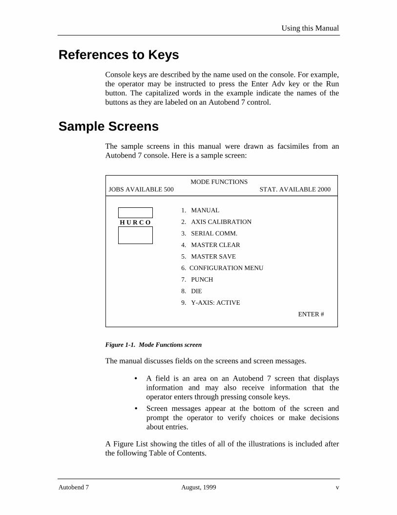
Sample ScreensThe sample screens in this manual were drawn as facsimiles from anAutobend 7 console. Here is a sample screen:
JOBS AVAILABLE 500MODE FUNCTIONS
STAT. AVAILABLE 2000
1. MANUAL
2. AXIS CALIBRATION
3. SERIAL COMM.
4. MASTER CLEAR
5. MASTER SAVE
6. CONFIGURATION MENU
7. PUNCH
8. DIE
9. Y-AXIS: ACTIVE
ENTER #
H U R C O
Figure 1-1. Mode Functions screen
The manual discusses fields on the screens and screen messages.
• A field is an area on an Autobend 7 screen that displaysinformation and may also receive information that theoperator enters through pressing console keys.
• Screen messages appear at the bottom of the screen andprompt the operator to verify choices or make decisionsabout entries.
A Figure List showing the titles of all of the illustrations is included afterthe following Table of Contents.

Programming and Operations Manual
vi Revision D Hurco

Autobend 7 August, 1999 vii
Table of Contents
Chapter 1 - System Basics
Press Brake, Autobend 7 Control, and Gauges ....................................................1-1Console Stop Button ................................................................................1-2
Power Cabinet and Console Location ......................................................1-3
Gauges......................................................................................................1-4
Axes’ Orientation .....................................................................................1-5
Safety Precautions ................................................................................................1-6Owner’s Responsibilities..........................................................................1-6
Machine Modification ..................................................................1-7Safety Hardware and Software.....................................................1-7Installation....................................................................................1-8Maintenance .................................................................................1-8Safety Signs..................................................................................1-9
Operators’ Responsibilities ....................................................................1-11
Training .....................................................................................1-11Clothing and Other Apparel .......................................................1-11Personal Care..............................................................................1-11
System Operation ...................................................................................1-12
Part Dimensions and Fixturing...............................................................1-14
Travel Limits ..........................................................................................1-14
Part Bending...........................................................................................1-15
Subsystem Failure ..................................................................................1-16
Electrical Systems ......................................................................1-16Procedures for Handling Printed Circuit Boards........................1-18
Fire Prevention and Fighting..................................................................1-19
Additional Safety Information................................................................1-19
Service Department ............................................................................................1-20Maintenance Schedule........................................................................................1-21
X-Axis ....................................................................................................1-21
R-Axis ....................................................................................................1-21
Y-Axis Downacting Hydraulic...............................................................1-21
Y-Axis Upacting ....................................................................................1-22
Y-Axis Positive Stop..............................................................................1-22
Control Console .....................................................................................1-22

Programming and Operations Manual
viii Revision D Hurco
Chapter 1- System Basics (continued)
Console Keypad Functions.................................................................................1-23Calibration..........................................................................................................1-26
Standard Downacting Hydraulic Calibration .........................................1-26
Upacting Linear Scale Calibration .........................................................1-27
Ram Calibration On Rotary Vane Press Brakes.....................................1-28
Tool 0 Calibration ..................................................................................1-29
Re-Calibration ....................................................................................................1-32Start-up Procedure..............................................................................................1-32Shut-down Procedure .........................................................................................1-33
Chapter 2 - Programming and Operations
Initial System Setup..............................................................................................2-2Mode Functions Screen............................................................................2-2
Manual Jog ...............................................................................................2-4
Axes Calibration.......................................................................................2-5
Serial Communications ............................................................................2-6
Master Clear .............................................................................................2-7
Master Save ..............................................................................................2-8
Configuration Menu .................................................................................2-9
Punch......................................................................................................2-11
Punch Programming...................................................................2-11Return to the Punch Number......................................................2-12Delete a Punch............................................................................2-12
Die .......................................................................................................2-13
Die Programming .......................................................................2-14Return to the Die Number ..........................................................2-15Delete a Die................................................................................2-15
Y-Axis Mode..........................................................................................2-16
Job Programming ...............................................................................................2-17Job List Screen .......................................................................................2-17
Single-Axis Job List Fields ........................................................2-20Two-Axis Job List Fields ...........................................................2-20
Job Setup Screen ....................................................................................2-21
Single-Axis Job Setup Fields .....................................................2-23Two-Axis Job Setup Fields ........................................................2-24
Deleting a Single Job..............................................................................2-25
Deleting All Jobs in Memory .................................................................2-25

Table of Contents
Autobend 7 August, 1999 ix
Station Programming..........................................................................................2-26Station Setup Screen...............................................................................2-26
Single-Axis Station Setup Fields ...............................................2-29Two-Axis Station Setup Fields ..................................................2-30
Two-Axis PLC Software Station Setup Fields...............2-31Two-Axis, Upacting, Linear Scale, PLC Software
Station Setup Fields..................................................2-31Two-Axis, Downacting, Hydraulic Ram Control
Station Setup Fields..................................................2-32R-Axis Station Setup Fields .......................................................2-33
Two-Axis R-Axis Station Setup Field ...........................2-33R-Axis Zero Position Setups..........................................2-33Multiple Depth Stop Ram Control Setup Field..............2-33
Station List Screen .................................................................................2-34
Inserting a Station...................................................................................2-36
Deleting a Station ...................................................................................2-36
Single Axis Quick Job Setup..............................................................................2-37Tool 0 Programming ..........................................................................................2-38
Tooling Fields ........................................................................................2-38
Tool 0 Job Programming Procedures .....................................................2-39
Selecting the Gauging Surface ...........................................................................2-45Flip Fingers ............................................................................................2-46
Gauge Blocks .........................................................................................2-46
Referencing the Gauging Surface.......................................................................2-47Setting the Retract at Pinch Sensor ....................................................................2-50
Upacting Press Brakes............................................................................2-50
Downacting Press Brakes.......................................................................2-52
Hydraulic Ram Control ..........................................................................2-53
Tool Qualification ..............................................................................................2-55Verifying Tool Height ............................................................................2-55
Verifying Die Opening and Shoulder Radius.........................................2-56
Measuring Die Opening .........................................................................2-56
TSD Measurement......................................................................2-57OSD Measurement .....................................................................2-58
Adjusting the Die Opening.....................................................................2-59
Measuring the Shoulder Radius .............................................................2-59
Adjusting the Shoulder Radius...............................................................2-59

Programming and Operations Manual
x Revision D Hurco
Chapter 2 - Programming and Operations (continued)
Run Cycle Selection ...........................................................................................2-60Auto Run ................................................................................................2-60
Punch and Die Tool Verification ...............................................2-61Adjusting Stations and Jobs .......................................................2-62
Single Run..............................................................................................2-64
Chapter 3 - Programming Examples
Gauge Dimension Programming..........................................................................3-1Enter a Job Number..................................................................................3-2
Program the Job Setup..............................................................................3-3
Program the First Station..........................................................................3-4
Program the Remaining Stations..............................................................3-5
Before Making a Trial Bend.....................................................................3-7
Making a Trial Bend and Forming Parts ..................................................3-7
X- and Y-Axes Programming Example ...............................................................3-9Program the Punch .................................................................................3-11
Program the Die .....................................................................................3-13
Enter a Job Number................................................................................3-15
Program the Job Setup............................................................................3-16
Program the First Station........................................................................3-17
Program the Remaining Stations............................................................3-19
Before Making a Trial Bend...................................................................3-21
Making a Trial Bend and Forming Parts ................................................3-22
X-, Y-, and R-Axes Programming Example ......................................................3-23Program the Punch ................................................................................3-24
Program the Example Die ......................................................................3-26
Enter the Job Number.............................................................................3-28
Program the Job Setup............................................................................3-29
Program the First Station........................................................................3-31
Program the Remaining Stations............................................................3-33
Before Making a Trial Bend...................................................................3-35
Making a Trial Bend and Forming Parts ................................................3-36

Table of Contents
Autobend 7 August, 1999 xi
Chapter 4- Communication Port
Optional RS-232-C Serial Port.............................................................................4-1Port Location ............................................................................................4-1
Connector Types.......................................................................................4-1
9-Pin D-Type Port Specifications.............................................................4-2
Pin Assignments.......................................................................................4-3
Cable Recommendations..........................................................................4-3
Cable Diagrams ........................................................................................4-4
25-Pin to 9-Pin Cable Diagram ....................................................4-49-Pin to 9-Pin Cable Diagrams.....................................................4-5
Cable Configurations................................................................................4-6
Chaapter 5- Troubleshooting
Troubleshooting Guide.........................................................................................5-1Hardware Diagnostics ..............................................................................5-2
Keyboard Test ..........................................................................................5-8
Application and Tooling Diagnostics.......................................................5-9
Screen Messages.................................................................................................5-10Glossary..............................................................................................................5-13
Index

Programming and Operations Manual
xii Revision D Hurco

Autobend 7 August, 1999 xiii
Figure List
Figure 1-1. Autobend 7 Control Console.................................................................................................. 1-2Figure 1-2. Side view of press brake with Autobend power cabinet ........................................................ 1-3Figure 1-3. Side view of press brake with Autobend 7 console ............................................................... 1-3Figure 1-4. Autobend Gauges ................................................................................................................... 1-4Figure 1-5. Typical Axes’ Configuration .................................................................................................. 1-5Figure 1-6. Warning Decal ....................................................................................................................... 1-9Figure 1-7. Caution Tape .......................................................................................................................... 1-9Figure 1-8. Warning and Danger Decals................................................................................................. 1-10Figure 1-9. Autobend 7 Console ............................................................................................................. 1-23Figure 1-10. Tool Calibration screen........................................................................................................ 1-29Figure 1-11. Tool Calibration screen with Die Top entered ..................................................................... 1-30Figure 1-12. Tool Calibration screen with Die Top and Die Bottom entered........................................... 1-31
Figure 2-1. Single-Axis Mode Functions screen....................................................................................... 2-2Figure 2-2. Two-Axis Mode Functions screen.......................................................................................... 2-3Figure 2-3. Manual Jog screen.................................................................................................................. 2-4Figure 2-4. Axes Calibration screen.......................................................................................................... 2-5Figure 2-5. Serial Communications screen ............................................................................................... 2-6Figure 2-6. Master Clear screen................................................................................................................ 2-7Figure 2-7. Master Save screen................................................................................................................. 2-8Figure 2-8. Configuration Menu screen .................................................................................................... 2-9Figure 2-9. Punch Library screen............................................................................................................ 2-11Figure 2-10. Die Library screen................................................................................................................ 2-13Figure 2-11. Mode Functions screen ........................................................................................................ 2-16Figure 2-12. Job Key ................................................................................................................................ 2-17Figure 2-13. Single-Axis Job List screen.................................................................................................. 2-18Figure 2-14. Two-Axis Job List screen with PLC software on Hurco Press Brake .................................. 2-19Figure 2-15. Single-Axis Job Setup screen ............................................................................................... 2-21Figure 2-16. Two-Axis Job Setup screen with PLC software on Hurco Press Brake ............................... 2-22Figure 2-17. Stat and New Stat Keys ......................................................................................................... 2-26Figure 2-18. Single-Axis Station Setup screen ......................................................................................... 2-27Figure 2-19. Two-Axis Station Setup screen with PLC software on Hurco Press Brake.......................... 2-28Figure 2-20. Single-Axis Station List screen ............................................................................................ 2-34Figure 2-21. Two-Axis Station List screen ............................................................................................... 2-35Figure 2-22. Insert and Delete Keys ......................................................................................................... 2-36Figure 2-23. Job List screen...................................................................................................................... 2-39Figure 2-24. Job Setup screen with PLC software for Hurco Press Brakes .............................................. 2-40Figure 2-25. Station Setup screen with PLC software on Hurco Press Brake.......................................... 2-41Figure 2-26. Need Die Information screen ............................................................................................... 2-42Figure 2-27. “Servos Not Latched Depress Run” message....................................................................... 2-43Figure 2-28. Tool Calibration Verification Warning screen ..................................................................... 2-44Figure 2-29. Flip Fingers and Gauge Block.............................................................................................. 2-45Figure 2-30. Zero Reference bars ............................................................................................................. 2-47Figure 2-31. Gauge calibration ................................................................................................................. 2-49Figure 2-32. Retract Sensor mounted on an upacting press brake ............................................................ 2-51Figure 2-33. Retract Sensor mounted on a downacting press brake ......................................................... 2-52Figure 2-34. Methods of Measuring the Die Opening .............................................................................. 2-56Figure 2-35. Measuring the TSD Die Opening......................................................................................... 2-57

Programming and Operations Manual
xiv Revision D Hurco
Figure 2-36. Measuring the Die Opening for standard software.............................................................. 2-58Figure 2-37. Tool Verification screen....................................................................................................... 2-61Figure 2-38. Single-Axis Auto Run screen ............................................................................................... 2-62Figure 2-39. Two-Axis Auto Run screen .................................................................................................. 2-63Figure 2-40. Single-Axis Single Run screen ............................................................................................. 2-64Figure 2-41. Two-Axis Single Run screen................................................................................................ 2-65
Figure 3-1. X-Axis Programming Example Part ....................................................................................... 3-1Figure 3-2. Job List screen........................................................................................................................ 3-2Figure 3-3. Job Setup screen..................................................................................................................... 3-3Figure 3-4. Station #1 Setup screen .......................................................................................................... 3-4Figure 3-5. Station List screen .................................................................................................................. 3-6Figure 3-6. X- and Y-Axes Example Part Bend Sequence........................................................................ 3-9Figure 3-7. Isometric View of X- and Y-Axes Example Part ................................................................. 3-10Figure 3-8. Punch measurements ............................................................................................................ 3-11Figure 3-9. Punch Library screen............................................................................................................ 3-12Figure 3-10. Die measurements ................................................................................................................ 3-13Figure 3-11. Die Library List screen......................................................................................................... 3-14Figure 3-12. Job Setup screen................................................................................................................... 3-15Figure 3-13. Job Setup screen................................................................................................................... 3-16Figure 3-14. Station Setup screen ............................................................................................................. 3-18Figure 3-15. X-, Y-, and R-Axes Example Part ........................................................................................ 3-23Figure 3-16. Punch.................................................................................................................................... 3-24Figure 3-17. Punch Library screen............................................................................................................ 3-25Figure 3-18. Die........................................................................................................................................ 3-26Figure 3-19. Die Library List screen......................................................................................................... 3-27Figure 3-20. Job List screen...................................................................................................................... 3-28Figure 3-21. Job Setup screen................................................................................................................... 3-30Figure 3-22. Station #1 Setup screen ........................................................................................................ 3-32Figure 3-23. Station List screen ................................................................................................................ 3-34
Figure 4-1. Male 9-Pin D-Type (DB-9) Connector................................................................................... 4-3Figure 4-2. 25-pin to 9-pin Cable Connections......................................................................................... 4-4Figure 4-3. 9-pin to 9-pin Cable Connections........................................................................................... 4-5Figure 4-4. 9-pin to 9-pin Cable Connections........................................................................................... 4-5
Figure 5-1. Keyboard Test Chart .............................................................................................................. 5-8

Autobend 7 August, 1999 1-1
Chapter 1
System Basics
This chapter prepares you to operate the Autobend 7 system by coveringthe following topics:
• Gauging System
• Safety Precautions
• Service Department
• Maintenance Schedule
• Autobend 7 Console Keypad Functions
• Calibration, Start-up, and Shut-down Procedures
Press Brake, Autobend 7 Control, and GaugesThe Hurco Autobend 7 Control system does not reduce or eliminate theneed for its users to follow the safety and operating instructions the pressbrake manufacturer provides. Do not ignore safety policies andsafeguarding circuits of the press brake’s controls. Errors in setup orprogramming can damage the press brake and cause severe personalinjury.
Be familiar with the following safety issues regarding the press brake andthe Autobend 7 system:
• Control Console Stop Button
• Power Cabinet and Console Location
• Gauges
• Axes’ Orientation

Programming and Operations Manual
1-2 Revision D Hurco
Console Stop Button
Always press the Stop button on the Autobend 7 console if a jam occursbetween the gauging surface and the tooling, or any time an emergencysituation arises involving the Autobend equipment.
Figure 1-1. Autobend 7 Control Console
Important
The Stop button does not force the press brake to stop unless aninterlock is wired from the Ram Enable relay (K1) to the press brakelogic.
The press brake’s Stop or E-Stop does not force the Autobend 7 tostop unless an interlock is wired from the press brake logic to theAutobend relay coil spare relay (K3).

System Basics
Autobend 7 August, 1999 1-3
Power Cabinet and Console Location
Before operating the gauging system on a press brake, become familiarwith the machine’s components. The figures below show press brakeswith the Autobend power cabinet and the control console attached.
Figure 1-2. Side view of press brake with Autobend power cabinet
Figure 1-3. Side view of press brake with Autobend 7 console

Programming and Operations Manual
1-4 Revision D Hurco
Gauges
The Autobend 7 control operates all models of Autobend gauges. Thesegauges are mounted to the rear of different types of press brakes asdiscussed in the “Component Mounting” chapter of the Installation andUpgrade manual. The figure below illustrates several models. The gaugebar length and horizontal adjustment varies among the gauges. The S8gauge can be mounted horizontally or vertically.
Figure 1-4. Autobend Gauges

System Basics
Autobend 7 August, 1999 1-5
Axes’ Orientation
The axes’ orientation is best observed from the front of the press brake asshown below. The X-axis positions the gauge bar for the desired flangelengths. The R-axis controls the height of the gauge bar so the gaugingsurface can be positioned as needed. The Y-axis controls the stoppingpoint of the press brake’s ram for the desired bend to occur. For hydraulicdownacting press brakes, the Y-axis can also control the ram’s openingheight and speed change point.
Figure 1-5. Typical Axes’ Configuration

Programming and Operations Manual
1-6 Revision D Hurco
Safety PrecautionsIt is important to follow all of Hurco and the press brake manufacturer’ssafety precautions to avoid personal injury, damage to the machine, andunproductive downtime. Installers must also follow the safety regulationsof their shops.
This section is included to address the safety hazards normallyencountered with the intended use and the foreseeable misuse of theAutobend 7 system. This product was intended to be used by trainedoperators who create metal bending programs either on the console or anoff-line system. These operators then run the programs to bend metal.While running the machines, the operators must use their experience andtraining to make any necessary adjustments and improve the efficiency oftheir programs.
This safety section describes common problems seen by Hurco Servicerepresentatives with suggestions for avoiding or dealing with the problemsin a safe manner. However, this information is not an exhaustivedescription of all of the possible misuses of the machine nor is it asubstitute for operator training, skill, and good judgment. Hurco does notaccept any liability for operator error.
Owner’s Responsibilities
The Autobend 7 system owner has several responsibilities regardingsafety. First, the owner must read this section of the manual andimplement the safety requirements described. Then the owner must becertain that the operators in the shop are properly trained and are using themachine as it was intended to be used. The owner must be certain that theoperator assigned to run the Hurco Autobend 7 is trained by Hurco.
If the Hurco trained operator leaves the shop, the owner is responsible forproviding training for the new operator assigned to run the machine. Theowner may wish to send operators to Hurco training classes or classes heldby distributors. Refer to the addresses and telephone numbers in thebeginning of this manual for Hurco subsidiaries. If there are no trainingsites in the vicinity of the shop, call the nearest Hurco facility forinformation about on-site training or other special training opportunities.
The owner must also establish proper procedures to prevent fires andprovide approved fire extinguishers to put out small fires. Of course, largefires must be extinguished by professional fire fighters. As a safetyprecaution, many shops have regular fire drills so that all employees knowtheir responsibilities during an emergency situation.

System Basics
Autobend 7 August, 1999 1-7
Machine Modification
The Autobend 7 system was designed to meet a wide range of customerneeds. If the owner feels that the machine needs to be modified in any wayto meet the special needs of the shop, Hurco recommends that the ownercall Hurco Technical Support or an authorized Hurco distributor formodification assistance and a written authorization to proceed.
If the owner modifies the machine in any way without Hurco’s assistanceand a written authorization, the machine warranty becomes invalid. Inaddition, such unauthorized modifications may cause safety hazards thatmay injure the operator and damage the machine. The owner is fullyresponsible for any accidents resulting from unauthorized modifications.
Safety Hardware and Software
If the owner or an operator modifies the hardware or software byremoving, altering, disabling, or tampering with any safety circuit, safetyswitch, or any safety operation and then continues to operate the machinewith those modifications, such operation is extremely hazardous, aforeseeable misuse of the machine, and voids the Hurco warranty. If theowner or an operator finds that such modifications have been made, thatperson must immediately switch off the machine and prevent use of themachine until it has been repaired. The owner must then contact a Hurcoservice representative for assistance in restoring the machine to safeoperation.
Important
In many locales, machine hardware or software modification tooverride safety protections and continued operation of such amodified machine is illegal and punishable with a fine and/orimprisonment.

Programming and Operations Manual
1-8 Revision D Hurco
Installation
The owner is responsible for proper site preparation before the machine isinstalled as described in the Installation and Upgrade Manual. A HurcoField Service Engineer or authorized distributor representative must installthe machine in the prepared location. This location must not subject themachine to uncontrolled cabinet temperatures or unfavorable workenvironment conditions that could cause electronic component failure.
If the owner decides later to move the press brake from its installedlocation, Hurco recommends that the owner call Hurco for assistance. Ifthis is not possible, Hurco recommends that the owner use a competentrigger with the necessary equipment to move the machine to the desiredlocation.
Maintenance
The owner must be certain that the shop’s press brake maintenancepersonnel are trained.
Warning
This machine must not be serviced, repaired, ormaintained by unqualified and untrained personnel.
If at any time the operator or owner determines that the electrical cabinetmust be opened, the power must be shut off to the machine before thedoors are opened.
The only exception to this rule is when the machine is being serviced forelectrical problems. Under those circumstances, only a competentelectronics technician directed by Hurco Field Service should perform thework.

System Basics
Autobend 7 August, 1999 1-9
Safety Signs
Safety-related signs pertaining to the Hurco Autobend 7 system are affixedto appropriate system components. These signs are illustrated below.Customers may order replacements at no charge by contacting Hurco.Please have the serial number for the Autobend 7 system available whenplacing an order.
Figure 1-6. Warning Decal
A warning sign (Hurco Part No. 703-0006-049) must be affixed at the rearof the control console. It also appears on safety decals that must be affixedto specific areas on the Autobend components. The warning signs alertoperators of the possibility of personal injury and damage to the pressbrake if they do not follow the described procedure.
Figure 1-7. Caution Tape
The yellow and black caution tape (Hurco Part No. 703-0003-009) mustbe applied across the top rear of the gauge carriage(s) and the gauge bar(s)alerting operators to a hazardous area.

Programming and Operations Manual
1-10 Revision D Hurco
Hurco ships safety-related decals like those illustrated below with eachAutobend 7 system. It is important that these decals are affixed asillustrated below. They pertain to operator safety and must be affixed tothe press brake as shown.
Customers may order replacements at no charge by contacting Hurco.Please have the Autobend serial number available when placing an order.
Figure 1-8. Warning and Danger Decals

System Basics
Autobend 7 August, 1999 1-11
Operators’ Responsibilities
To avoid serious personal injury, damage to the machine, andunproductive down-time, the operator must pay careful attention to safetyprecautions and proper maintenance of the machine. Press brake operationis often a dangerous task, so operators must stay alert and be aware ofpotential hazards. Operators must also follow the safety regulations oftheir shops.
Training
All operators must be trained operators in order to operate an Autobend 7system. The operators who are going to run the press brake must betrained by Hurco or a Hurco authorized distributor. Before attempting tooperate the machine, the operator should study this manual and becomefamiliar with the machine functions and safety features.
While studying the manual, the operator should make special note of thecaution and warning messages in the manuals and all warning andinstruction plates/decals on the press brake.
Clothing and Other Apparel
Operators should always wear eye protection and safety shoes while in thework area. Safety glasses with side shields are recommended. Theoperator should not wear items such as loose-fitting clothing, watches,necklaces, rings, and neckties that could become caught in the movingparts of the machine.
Personal Care
Operators must follow established working practices and personal hygienestandards. As part of this effort, they must avoid frequent or prolongedskin contact with fluids and oils on the sheet metal. Some operators weargloves or use a special hand cream to protect their hands from thesechemicals. If operators get chemicals on their hands, they must wash theirhands immediately upon leaving the machine and before taking a break.They must also change clothing that has become contaminated with fluidsand oils.
For complete information about handling industrial chemicals used inmachining, refer to the international Control of Substances Hazardous toHealth (COSHH) materials from the chemical suppliers.

Programming and Operations Manual
1-12 Revision D Hurco
System Operation
When operating an Autobend 7 system, always follow these safety rules:
Warning
• Review all safety information and operating instructions thepress brake manufacturer provides before attempting anyoperation.
• Use proper point of operation safeguarding.
• Use the press brake’s Emergency Stop circuits to controlemergency situations involving the press brake.
• Check the installation of the carriage arrestor bars beforeoperating the system.
• Adjust the gauging system from the rear of the press brake.
• When testing the Autobend 7 system, check the ramadjustment before stroking the press brake. Set the downlimit switch as required per the press brake’s manufacturer.Tooling must not bottom out before the ram reaches the lowend of its stroke.
• Be sure that the gauge bar and flip fingers are correctlyreferenced to the press brake’s tooling before attemptingoperation.
• Turn the operator control(s) to Off before attempting toadjust the system.

System Basics
Autobend 7 August, 1999 1-13
• Keep hands out of the point of operation and clear of thepress brake’s forming tools.
• Never reach across the press brake tooling to make anyadjustment.
• Never attempt to make any adjustment to the system byreaching through the press brake point of operation.
• When testing and running the Autobend 7 system, neverattempt to bend metal that requires tonnage beyond thecapacity of the press brake or the tooling, whichever is less.
• Never operate a disassembled system.
• Disconnect the external power source before attempting toconnect or make adjustments within the power supply boxor the Autobend power supply cabinet. Only qualifiedpersonnel should service this equipment.
• Before operating the system be sure that installers oroperators will not be struck by the rapid movement ofthe gauge bar. Also make certain that nothing interfereswith the gauge movement in either direction.
• To prevent damaging the tooling and harming the operator,tooling dimensions must be accurate when configured with aY axis.
• To prevent damaging the tooling and harming the operator,the Die Opening Measurement must be measured correctly.
For controls on Hurco Press Brakes, the Die MeasurementPoint field of the Die Library List screen must be set to OSDor TSD depending on the tooling measurement. Refer to the“Die” section of the “Programming and Operations” chapterfor details.
Note
This list does not include all of the possible hazards regarding theAutobend 7 system.
Programming and Operations Manual
1-14 Revision D Hurco
Part Dimensions and Fixturing
Operators should never bend a part on the gauging system that is largerthan the working surface of the press brake or juts out on any side beyondthe edges of the press brake. If a part requires a range that is greater thanthe guarding allows, the work must be performed on another machinehaving the necessary work volume capability.
Operators must follow procedures for referencing the bending materialbefore starting the machine. Remember that loose objects, such aswrenches and chuck keys, can become flying projectiles if not removedfrom the gauge bar before the machine is started. Operators should also beaware of protruding machine members (such as hoses, piping, ductwork)when working around the machine.
Travel Limits
Safety limit switches provided for each system must not be removed orbypassed in order to obtain more travel or take short cuts. Serious damageto the machine and personal injury to the operator may result from suchactions. It is also dangerous to bend a part that requires operation outsidethe limits of the machine. A larger press brake should be used for such apart.

System Basics
Autobend 7 August, 1999 1-15
Part Bending
Operators should always know the locations of the Stop button on thepress brake and console. The operator must be very careful when workingin the area of the gauge. To prevent injury, the gauge should becompletely stopped before the operator attempts to make adjustments to awork piece or the gauging surface.
Warning
When running programs, operators should alwaysfollow these rules:
• Never press the Run button without knowing exactly whatthe machine will do!
• Never start the machine when the back gauge is in contactwith the work piece.
• Never stand in the rear inside area of the press brake whilethe gauge is moving.
• Never leave the machine unattended.
The operator must work within reach of the Stop buttons and must be ableto observe the operation of the gauge. If the operator is running a programand cannot reach a Stop button nor observe the gauge, that is consideredunattended operation and is viewed as a foreseeable misuse of themachine.

Programming and Operations Manual
1-16 Revision D Hurco
Subsystem Failure
Maintenance personnel and trained operators need to understand themaintenance requirements and possible problems associated with the pressbrake subsystems. They can become familiar with the subsystemmaintenance requirements by studying the press brake’s MaintenanceManual and by attending a Hurco training class.
Electrical Systems
Clean AC source power, as defined in the ANSI/NFPA 79 standard, isessential to the successful operation and continued reliability of themachine. Therefore, the gauging system must be properly connected to itspower source as described in detail in the Installation and UpgradeManual. The machine must be attached to a dedicated, fused, and isolatedline with incoming power that matches the specified, factory-wired, powercabinet voltages, and current requirements of the system.
Warning
If the machine is not properly connected to its powersource, there may be noise on the line that will affectmachine safety, performance, and the warranty. Inaddition, brownout conditions may occur in the shop,and the electrical components may fail and requirereplacement.

System Basics
Autobend 7 August, 1999 1-17
Use these electrical safety guidelines before operating the Autobend 7system:
1. Always provide a clean source of electrical power with aseparate dedicated incoming power line (hot, neutral andground wire).
2. This source must be free of inductive loads that might causehigh-frequency noise. Ensure that this source is free fromhigh/low voltage, spikes, surges, and noise.
3. The machine’s electrical control systems are interconnectedto terminate at the central point ground terminal locatedinside the Autobend power cabinet. This single point groundmust be connected to the ground circuit of the electricalpower source so that it provides only one conducting path(between the machine and the extension cord). This methodof grounding prevents an unwanted ground loop that mayappear.
4. Route all Autobend 7 cables to prevent close contact (6" -10", 150 mm. - 250 mm.) with any press brake control,voltage line, motor, or other noise-generating devices.
5. Attach all system cables properly to the press brake’s frame.Loop cables with excessive length. Use the extra large tiewraps and 3/8" self-tapping screws provided to attach thecables to the frame.

Programming and Operations Manual
1-18 Revision D Hurco
Procedures for Handling Printed Circuit Boards
Static charges are present at all times and in all environments. Damage tosensitive electronics occurs at lower voltage levels than people can sense.Static damage may cause total failure or degrade the circuits’ performanceand can eventually lead to intermittent or total failure. Prevent componentdamage by discharging static electricity to a ground. Follow theprocedures below.
Before touching, adjusting, or removing a printed circuit board (PCB),wear a wrist strap grounded to the cabinet or enclosure ground point. If agrounding wrist strap is not available, touch a grounded point within theenclosure each time before touching a PCB or electronic assembly. Anexample of a grounding point is the metal cabinet’s screws.
Caution
Limit the direct handling of the PCB to reduce the chance ofdamage.
Keep the PCB in a protective bag until it is installed. Use statichandling procedures before opening the bag and removing the circuitboard. Return all replaced PCBs to the static protective bag.

System Basics
Autobend 7 August, 1999 1-19
Fire Prevention and Fighting
There are some obvious causes of fires that should be avoided in all shops:
• Storing or handling flammable materials near heat sources.
• Failing to keep the work area clear of debris such as shopcloths, cartons, and other shop supplies that could catch fire.
If a fire does occur, the operator must press the Stop button on the consoleand on the press brake and activate the factory fire alarm system toevacuate personnel who are not directly involved with extinguishing asmall fire. Shop personnel may be able to put out small fires usingextinguishers approved for the conditions in their shops. However if it isclear the fire is uncontrolled or too large for the shop extinguishers,professional fire fighters must be called after all shop personnel areevacuated.
If a fire has occurred and the shop personnel have extinguished it, it maystill be wise to contact the fire department or fire prevention authorities foradvice to be certain the fire has been completely extinguished and to helpprevent future fires. Fire extinguishers should be tested for properoperation at least three times a year by a trained and certified inspector.
Additional Safety Information
For additional safety information Hurco recommends the followingsources:
1. National Safety Council
444 N. Michigan Avenue
Chicago, Illinois 60611
2. State, provincial, and local safety codes.
3. Loss prevention department of a worker’s compensationcarrier.
4. Manufacturer of the press brake.
Programming and Operations Manual
1-20 Revision D Hurco
Service Department
The goal of Hurco’s Service Department is to provide customers withservices necessary to help ensure success in their investment. If customersexperience problems with the Autobend 7 system components such asscreen errors, lack of power to the components, or gauge performance thatare not solved by suggestions in the “Troubleshooting” chapter, theyshould contact Hurco’s Service Department by calling the appropriatephone number listed in the first section of this manual. The ServiceDepartment personnel will attempt to correct problems in an efficient andtimely manner, saving the company downtime.
Please provide the following information when calling Hurco’s ServiceDepartment:
1. The serial number of the machine is located on the door ofthe power cabinet’s data plate.
Record the serial number here for reference:
2. Company name and telephone number.
3. Your name and telephone extension.
4. A brief, accurate description of the problem and its specificsymptom(s).
The Hurco Service Department is committed to helping customers obtainthe maximum benefits from investing in its products.

System Basics
Autobend 7 August, 1999 1-21
Maintenance Schedule
For best results in keeping the Autobend 7 system in good condition,follow this maintenance schedule:
X-Axis
1. Clean and lubricate the leadscrew and ways on a weeklybasis; if the shop environment is dirty, clean them daily. Uselightweight oil to lubricate lead screw, and grease tolubricate the ways.
2. Every six months inspect belts, couplings, and pulleys forwear or looseness. Tighten as necessary.
3. Every six months inspect the gauge harness for cutinsulation or wires. Replace if damaged.
R-Axis
1. Clean and lubricate the leadscrew and ways on a weeklybasis; if the shop environment is dirty, clean them daily. Uselightweight oil to lubricate lead screw and grease tolubricate the ways.
2. Every six months inspect belts, couplings, and pulleys forwear or looseness. Tighten as necessary.
3. Every six months inspect the gauge bar’s mounting bolts forlooseness. Level the bar and tighten screws as required.
4. Every six months inspect the R-axis harness for cutinsulation or wires. Replace if damaged.
Y-Axis Downacting Hydraulic
1. Every six months check the linear scale mounting bolts,linkage rod, rod mounting bolts, and bracket for looseness.Tighten as required.
2. Every three months remove the linear scale cover and cleanand lubricate the linear way. Use lightweight oil.
3. Every six months inspect the Y-axis linear scale harness forcut insulation or wires. Replace if damaged.

Programming and Operations Manual
1-22 Revision D Hurco
Y-Axis Upacting
1. Clean and lubricate the leadscrew on a weekly basis usinglightweight oil; if the shop environment is dirty, clean thelead screw daily.
2. Every six months inspect belts, couplings, and pulleys forwear or looseness. Tighten as necessary.
3. Every six months inspect the Y-axis harness for cutinsulation or wires. Replace if damaged.
Y-Axis Positive Stop
1. Every six months inspect belts, couplings, and pulleys forwear or looseness. Tighten as necessary.
2. Every six months inspect the Y-axis harness for cutinsulation or wires. Replace if damaged.
Control Console
1. Clean the front panel and screen with a mild detergent on aweekly basis; daily if the shop environment is dirty.
2. Master Save all part programs on a monthly basis.
3. Every six months inspect the control console harness for cutinsulation or wires. Replace if damaged.

System Basics
Autobend 7 August, 1999 1-23
Console Keypad Functions
The illustration below shows the Autobend 7 console with its membranekeypad, Run and Stop buttons, and Protect keyswitch.
Figure 1-9. Autobend 7 Console

Programming and Operations Manual
1-24 Revision D Hurco
The membrane keys on the console keypad perform the followingfunctions:
Key Function
Mode Displays the Mode Functions screen.
Job Displays the Job List screen and advances the cursorto the next Job # field.
Stat Displays the Station List screen and advances thecursor to the next Station # field.
New Stat Creates a new station by duplicating the last stationin the job presently selected. Adds this new stationat the end of the list.
Back Moves the cursor backwards one position until thecursor is at the top of the screen. Thereafter, movesback to the previously displayed screen.
Number Pad
(0 through 9)
Contains numerical keys used for data entriesrequiring number values.
Yes + Enters Yes for questions requiring a positiveresponse and a “+” sign for prompts requiringnumber inputs. Positive numbers do not require a“+” sign.
No - Enters No for questions requiring a negativeresponse and a “-” sign for prompts requiringnumber inputs.
Enter Adv Advances the cursor to the next prompt. Alsoadvances the gauge to the next programmed stationwhen in Single Run mode.
Next Advances the cursor to the next programmedStation screen when in Station Setup.
Insert In the Station List screen, inserts a new station atthe location displayed in the Station # prompt.
Delete Erases the selected Job # or Station # from memory.
Out � Moves the gauge backwards when operating inManual Jog.
In � Moves the gauge forward when operating in ManualJog.
Clear Clears the input data for any entry requiring anumerical input.
• Inserts a decimal point.
System Basics
Autobend 7 August, 1999 1-25
The Run and Stop buttons perform the following functions:
Button Function
Run Starts operations in Auto mode; press again and theoperation runs in the Single mode.
Stop Stops all axes operation; screen blanks.
The Protect Keyswitch limits access to programming functions anddisables programming, but it allows operation of the gauges. The ProtectKeyswitch must be in the vertical, Off position to enable programmingfunctions.

Programming and Operations Manual
1-26 Revision D Hurco
Calibration
The axes automatically calibrate and position to the first station duringstart-up when a job is programmed and the Run button is pressed. Thereare additional calibration procedures to follow for upacting linear scalepress brakes, rotary vane press brakes equipped with ram control, and forTool 0 Job programming.
Standard Downacting Hydraulic Calibration
The following procedures apply to all downacting hydraulic press brakes:
1. Program the job. Refer to the “Programming andOperations” chapter for more information about jobprogramming.
2. Press the Run button.
3. Verify that the tooling being used matches the toolingprogrammed.
4. Press the Run button.
5. Raise the ram to the Top of Stroke (T.O.S.).
6. Press the Back button.
7. Lower the ram downward until the calibration mark islocated.
The calibration is complete when the calibration mark is passed. Thesystem positions the axes for the displayed Station.

System Basics
Autobend 7 August, 1999 1-27
Upacting Linear Scale Calibration
The following procedures apply to Hurco PH Series upacting press brakesequipped with PLC software and a linear scale:
1. Program the job. Refer to the “Programming andOperations” chapter for more information about jobprogramming.
2. Press the Run button.
3. Verify that the tooling being used matches the toolingprogrammed.
4. Press the Run button. All servo axes are calibrated beforethe linear scale is calibrated.
5. When the servo axes calibration is complete, this messageappears on the screen:
Move Ram to Full Open Position
Press Back Key
6. Press the Back key. This message appears on the screen:
Move Toward Full Closed Position
to Calibrate
7. Raise the ram until the calibration mark is located. Thecalibration is complete when the calibration mark is passed.The system positions the axes for the displayed Station.
Important
If the marker pulse is not located, the ram moves up until the punchbottoms out into the die. Ensure that the tooling will withstand theavailable bending force.

Programming and Operations Manual
1-28 Revision D Hurco
Ram Calibration On Rotary Vane Press Brakes
When calibrating the ram on a rotary vane press brake, both the ramadjustment and stroke adjustment assemblies must be positioned to allowthe ram to reach its maximum opening. The ram adjustment is made toallow the tooling to meet when the stroke adjustment is at the bottom of itstravel. Calibrate the ram on a rotary vane press brake by following theseinstructions:
1. Start the press brake and the Autobend 7 following thedirections in the previous section.
2. Using the ram adjustment assembly raise the ram to itshighest opening position.
3. Position the indicator on the stroke control assembly to theside that is controlled by the Autobend 7 control.
4. Raise the ram so the stroke control is at the top of its travel.
5. Select a job on the console and press the Run button. Referto the “Job Programming” section of the “Programming andOperations” chapter for more information about selectingjobs.
6. The axes move toward their calibration positions and thescreen displays the message “Move Ram to T.O.S. and PressBack.”
7. When the console displays the message “Move Ram Downto Calibrate,” inch the ram down past the calibration mark.
8. After the ram is past the calibration mark, the Autobend 7moves the axes to their programmed positions. Continuemoving the ram down until it reaches the bottom of theindicator on the stroke control assembly.
9. Inch the ram down with the ram adjustment assembly untilthe punch is at the deepest penetration required.
10. Raise the ram to its programmed open height. If the job hasmore than one station, the axes advance to Station 2.
11. This completes the ram calibration procedure. Reset the jobto Station 1 and operate.

System Basics
Autobend 7 August, 1999 1-29
Tool 0 Calibration
Before running a Tool 0 job, calibrate the axes if the system has notcalibrated since powering up.
1. After completing the Die Information screen (refer to the“Programming and Operations” chapter for more Tool 0Programming information), press the Run button to beginram calibration. The Calibration screen appears with thecursor positioned at the Die Top field.
>>>> DIE TOP ****
DIE BOTTOM ****
CALIBRATION: 7.296
TOOL CALIBRATION
Figure 1-10. Tool Calibration screen
Programming and Operations Manual
1-30 Revision D Hurco
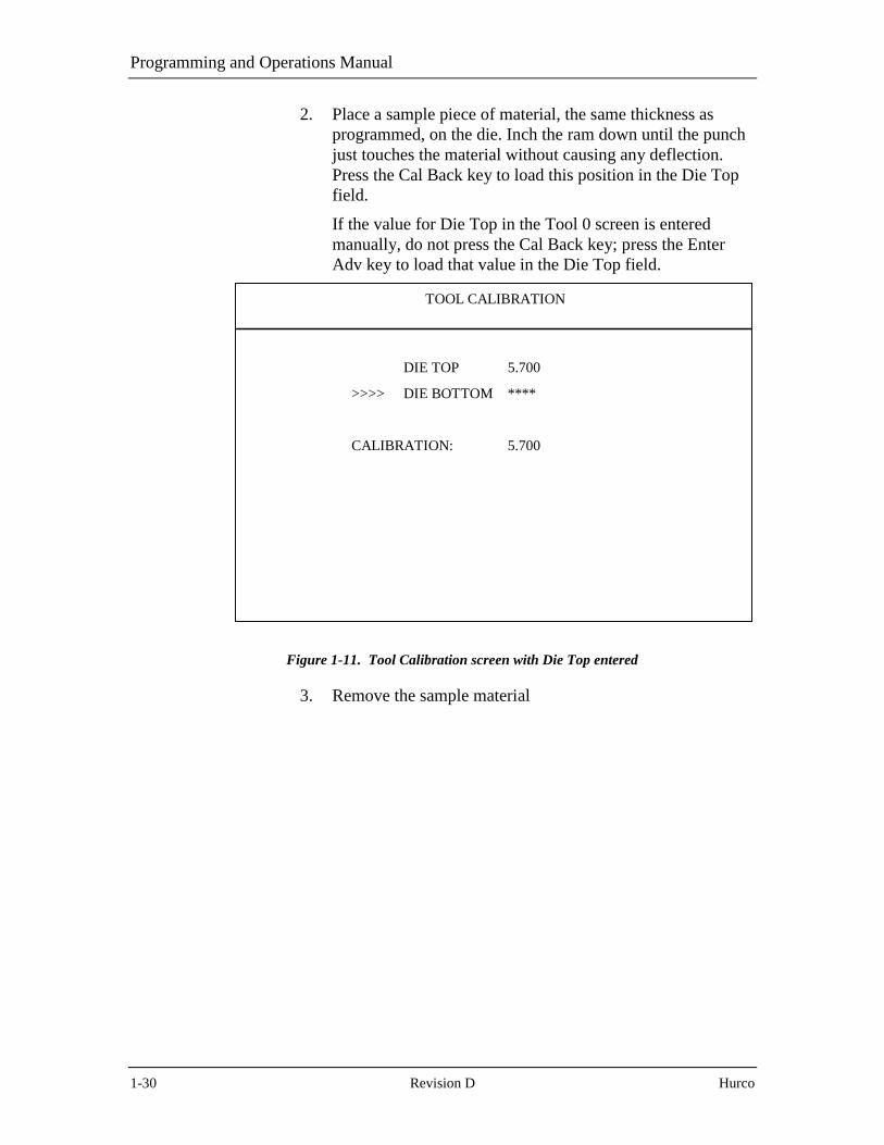
2. Place a sample piece of material, the same thickness asprogrammed, on the die. Inch the ram down until the punchjust touches the material without causing any deflection.Press the Cal Back key to load this position in the Die Topfield.
If the value for Die Top in the Tool 0 screen is enteredmanually, do not press the Cal Back key; press the EnterAdv key to load that value in the Die Top field.
DIE TOP 5.700
>>>> DIE BOTTOM ****
CALIBRATION: 5.700
TOOL CALIBRATION
Figure 1-11. Tool Calibration screen with Die Top entered
3. Remove the sample material

System Basics
Autobend 7 August, 1999 1-31
4. The cursor advances to the Die Bottom field. Inch the ramdown until the tooling bottoms out. Press the Enter Adv keyto load this position in the Die Bottom field. OK appears inthe Die Bottom field.
DIE TOP 5.700
>>>> DIE BOTTOM OK
CALIBRATION: 5.196
*** MOVE RAM UP TO T.O.S.***
DEPRESS RUN
TOOL CALIBRATION
Figure 1-12. Tool Calibration screen with Die Top and Die Bottom entered
5. Once the “Move Ram to T.O.S.” message is displayed, raisethe ram fully.
6. Press the Run button to begin operation.
7. The calibration is complete.

Programming and Operations Manual
1-32 Revision D Hurco
Re-CalibrationTo clear the axes’ calibration in the Mode Functions screen, perform thefollowing steps:
1. Press the Mode key to display the Mode Functions screen.
2. Select the Axes Calibration screen. The present axes’calibration states are displayed.
3. Press the Clear key to clear all prior calibration values. TheMode Functions screen appears.
4. Press the Run button to start re-calibration.
Start-up ProcedureFollow these instructions to start up the Autobend 7 control:
1. Turn on the power to the control using the switch on the sideof the Autobend power cabinet. The Job List display appearswith the most recently programmed job on the screen.
2. Turn on the power to the press brake and start the pumpmotor by following the manufacturer’s instructions.
3. Select a job from memory by entering a Job Number in theJob List screen. Program the job if it is not alreadyprogrammed. (Refer to the “Programming and Operations”chapter for more information.)
4. The axes calibrate and then position to the first station.
5. The bending operation may begin.

System Basics
Autobend 7 August, 1999 1-33
Shut-down ProcedureTo shut down the control, follow these steps:
1. Block the press brake’s ram and turn off the power to thepress brake by following the manufacturer’s instructions.
2. Press the Stop button. This blanks the screen and de-energizes the axes.
3. For an extended shut-down, select Master Save from theMode Functions screen, and turn off the power to theAutobend 7 and the press brake. The backup battery is ratedfor 15 days. The Flash EPROM memory device operatesindefinitely. For more information refer to the “MasterSave” section of the “Programming and Operations”chapter.

Autobend 7 August, 1999 2-1
Chapter 2
Programming and Operations
The Autobend 7 has multiple screens for auxiliary and programmingfunctions. The mode functions screens are for auxiliary functions, and themain screens—Job and Station—are dedicated to programming andsystem operation.
Auxiliary functions not directly related to programming and running arecontained in the Mode Functions screens. These functions pertain to themanual positioning of the gauge(s), calibration of the axes, management ofthe memory, and the system configuration.
The Autobend 7 uses prompt programming. Programs are referred to asjobs, and bends are referred to as stations. Tooling libraries are used toprogram punches and dies. Programming a job consists of two parts:
1. Programming the Job.
2. Programming the Stations.
The system has two Run modes: Auto and Single. In the Auto Run mode,the gauge advances automatically with each ram stroke. In the Single Runmode, the gauge remains stationary until the Enter Adv key is pressedregardless of how many ram strokes are made.
The fields on these screens vary depending on the axes or press brakeconfiguration:
• For systems that only control a back gauge (X-axis), the Joband Station screens do not display information pertaining toram control, tooling, and gauge height.
• For systems that only control the back gauge and gaugeheight, the screens do not display information pertaining toram control.
• For systems on Hurco Press Brakes, screens contain fieldsfor programming Part Length Compensation (PLC). Refer tothe “Die,” “Two-Axis Station Setup,” “Die Programming,”and “Measuring Die Opening and Shoulder Radius” sectionsfor details.
Programs can also be backed up on a non-volatile Flash EPROM by usingMaster Save in the Mode Functions screen. This saves all information incase of a battery backup failure during a power outage.

Programming and Operations Manual
2-2 Revision D Hurco
Initial System Setup
The Mode Functions screen, displayed by pressing the Mode key, allowsinitial system setup functions not included in the Job and Stationoperations.
Mode Functions Screen
From this screen the operator can select to manually jog the gauges,manage memory, calibrate the axes, and set the system configuration. Usethe Up and Down arrow keys to move the cursor to highlight selectionsand press the Enter Adv key after making selections.
Important
The Protect keyswitch must be in the vertical, Off position to enableprogramming functions.
Below is a Mode Functions screen for a single-axis configuration:
JOBS AVAILABLE 500MODE FUNCTIONS
STAT. AVAILABLE 2000
1. MANUAL
2. AXIS CALIBRATION
3. SERIAL COMM.
4. MASTER CLEAR
5. MASTER SAVE
6. CONFIGURATION MENU
ENTER #
H U R C O
Figure 2-1. Single-Axis Mode Functions screen

Programming and Operations
Autobend 7 August, 1999 2-3
Here is a Mode Functions screen for a two-axis configuration:
JOBS AVAILABLE 500MODE FUNCTIONS
STAT. AVAILABLE 2000
1. MANUAL
2. AXIS CALIBRATION
3. SERIAL COMM.
4. MASTER CLEAR
5. MASTER SAVE
6. CONFIGURATION MENU
7. PUNCH
8. DIE
9. Y-AXIS: ACTIVE
ENTER #
H U R C O
Figure 2-2. Two-Axis Mode Functions screen

Programming and Operations Manual
2-4 Revision D Hurco
Manual Jog
Axes can be positioned manually by selecting Manual Jog from the ModeFunctions screen.
1. To begin jogging the axes, press the Run button.
2. Press the Next key to select the axis to jog. The arrow cursor(>>>) toggles between the axis selections (X-Axis Dim, Y-Axis Dim, and R-Axis Dim).
3. Select the axis jog speed by pressing the Enter Adv key.
a. The arrow cursor toggles between Rapid Jog, SlowJog, ± 0.100 in., ± 0.010 in., and ± 0.001".
b. If the axes have not been calibrated, the axisposition displays Uncalibrated. The Y-axis has notbeen calibrated in the sample screen below.
c. There is no R-axis so no text message appearsunder that heading on the screen.
The values displayed are absolute, so tooling has no impact on them.Below is a sample Manual Jog screen:
MANUAL JOG
>>> X-AXIS DIM.
24.000
R-AXIS DIM.
Y-AXIS DIM.
UNCALIBRATED
RAPID JOG
>>> SLOW JOG
+ 0.100 IN
+ 0.010 IN
+ 0.001 IN
Figure 2-3. Manual Jog screen

Programming and Operations
Autobend 7 August, 1999 2-5
Axes Calibration
To check the axes’ calibration status and the marker pulse position duringcalibration, select Axis Calibration from the Mode Functions menu. Thescreen below appears:
JOBS AVAILABLE 499AXIS CALIBRATION
STAT. AVAILABLE 1999
X1
Y1
R1
UNCALIBRATED
UNCALIBRATED
UNCALIBRATED
158.4
179.4
104.7
DEPRESS CLEAR TO RESET. . .
Figure 2-4. Axes Calibration screen
In the first column on this screen, the back gauge appears as X1, X2, etc.Optional ram control is listed as Y1, and the optional automatic gaugeheight is listed as R1, R2, etc.
The calibration status appears in the middle column as Calibrated,Calibrating, or Uncalibrated. The encoder marker pulse position shows upunder the third column as an angle. Obtain the proper spacing for themarker pulse to the calibration switch with this angle.
The numbers shown in the third column coincide with the amount ofmotor rotation from the calibration switch contact transition. For example,when 180 is listed, it signifies that the marker pulse occurs ½ of a motorrevolution from the switch. The acceptable range for the marker is 90° to270° with 180° being the target value. An asterisk (*) signifies that themarker pulse location is outside the acceptable range.
To re-calibrate the axes press the Clear key. The axes uncalibrate and theMode Function screen appears. The next time the Run button is pressed,the axes automatically re-calibrate.

Programming and Operations Manual
2-6 Revision D Hurco
Serial Communications
The entire memory may be transferred to or from a personal computer viathe RS-232-C port located on the top of the Autobend 7 power cabinet.This feature is available when used with the optional Hurco softwarepackage. Refer to the “Communication Port” chapter for more informationabout the RS-232-C port.
Select Serial Communications from the Mode Functions menu.Communication direction is selected to perform one of the followingfunctions:
Write Program to PC Transfers the entire memory from theAutobend 7 to the PC.
Read Program From PC Transfers an entire memory part program filefrom the PC to the Autobend 7.
The baud rate selection is displayed below the Write/Read fields on thescreen. This rate is selected in the Configuration Menu. Refer to the“Configuration Menu” section later in this chapter for more information.
Select Write Program to PC or Read Program from PC, and the controlwaits until the PC commands it to begin transferring. The message“Writing” or “Reading” appears in the lower left-hand corner of thescreen until the transfer is complete.
JOBS AVAILABLE 499SERIAL COMM.
STAT. AVAILABLE 1999
1 - WRITE PROGRAM TO PC
2 - READ PROGRAM FROM PC
9600 BAUD
ENTER #
Figure 2-5. Serial Communications screen

Programming and Operations
Autobend 7 August, 1999 2-7
Master Clear
Master Clear erases all battery-backed memory of the Autobend 7. SelectMaster Clear from the Mode Functions menu, and the message “Are YouSure? No” appears at the bottom of the screen. To enter a Yes responseand erase the memory, press the Yes key.
JOBS AVAILABLE 499MASTER CLEAR
STAT. AVAILABLE 1999
ARE YOU SURE? NO
Figure 2-6. Master Clear screen

Programming and Operations Manual
2-8 Revision D Hurco
Master Save
To save the battery-backed memory in a non-volatile Flash EPROMdevice, select Master Save from the Mode Functions menu. The screenbelow appears with the “Saving Part Programs...” message.
Master save the memory regularly to reduce the possibility of memoryloss due to a battery backup failure during a power outage.
JOBS AVAILABLE 499MASTER SAVE
STAT. AVAILABLE 1999
SAVING PART PROGRAMS. . .
Figure 2-7. Master Save screen
Important
Memory is maintained with power Off, provided the battery isfunctional.

Programming and Operations
Autobend 7 August, 1999 2-9
Configuration Menu
Although the Configuration Menu is set at the factory to suit mostapplications, changing some of the parameters may better suit a particularapplication. Below is a Configuration Menu with the factory-setparameters:
CONFIGURATION MENU
MEASUREMENT UNITSLANGUAGE TYPEAUDIBLE BEEPERSTART-UP SCREENMODE OF OPERATIONRETRACT AT PINCHBAUD RATE
ENGLISHENGLISHDISABLEDHURCO LOGONORMAL (RUN) MODEDISABLED9600
SAVE AND EXITEXIT WITHOUT SAVING
USE ARROWS, +, -, TO SELECT ITEM, USE (ENTER) TO SELECT ENTRIES
Figure 2-8. Configuration Menu screen
To change the Configuration Menu parameters, follow these directions:
1. Press the Mode key to display the Mode Functions screen.Select the Configuration Menu.
2. Press the � key to move the cursor up one field.
3. After selecting the field to be changed, press the Enter Advkey. The fields toggle between choices each time the EnterAdv key is pressed. These choices are listed on thefollowing page.

Programming and Operations Manual
2-10 Revision D Hurco
The fields on the Configuration Menu screen perform the followingfunctions:
Field Function
MeasurementUnits
Selects the measurement units (English or metric) forprogramming.
Language Type Selects the text language used by the Autobend 7.
Audible Beeper When Enabled, every key pressed sounds a beeper toverify selection entry. Selecting Disabled turns Off thebeeper.
Start-up Screen Switches the logo displayed on the Mode Functionsscreen.
Mode ofOperation
Selects whether the Autobend 7 operates in a DemoMode or a Normal (Run) Mode. Normal (Run) Modemust be selected to operate gauges.
Retract at Pinch Selects whether the gauge retracts at the materialpinching point. Possible selections are Enabled orDisabled.
The selections for systems with hydraulic downactingram control are Disabled, Linear Scale @ 5%, LinearScale @ 10% or Linear Scale @ 15%.
Baud Rate Selects the communication rate for the RS-232-C port:9600 or 19200 baud.
Save and Exit Saves all changes made to the Configuration Menu.
If changes are made, they must be saved prior to exitingthe Configuration Menu or the previous values will berestored.
Exit WithoutSaving
Exits to the Mode Function screen without acceptingany changes made in the Configuration Menu.

Programming and Operations
Autobend 7 August, 1999 2-11
Punch
The Autobend 7 console can store up to 45 punches in memory forsystems equipped with ram control. The stored information allows theAutobend 7 to recall the ram positioning information so parts can be madequickly without having to re-calibrate the ram. Select Punch in the ModeFunctions menu and the Punch Library screen appears.
Punch Programming
Follow these steps to program a punch:
1. While in the Punch Library screen, press the Next key to listthe next screen of punches.
2. Press the Back key to list the previous screen of punches.
3. Use the up or down arrow keys to navigate to the punchnumber.
4. Press the Enter Adv key to enter the punch numberhighlighted by the cursor. That punch can now beprogrammed or edited.
Note
The Punch Library is only displayed when the system is equippedwith ram control (Y-axis).
PUNCH LIBRARY
NUMBER:
123
>>>456789
101112131415
RADIUS
0.0320.0130.3000.0150.025
HEIGHT
2.1253.3753.7503.2502.500
ANGLE
89.045.060.075.590.0
OFFSET
0.3750.0000.000.1000.000
+, - TO SELECT TOOL | NEXT - NEXT PAGE | CURRENT TOOL # 4<ENTER> TO EDIT | BACK - PREV PAGE | ENTER # __
Figure 2-9. Punch Library screen
Programming and Operations Manual
2-12 Revision D Hurco
Here are definitions for the fields in the Punch Library screen:
Field Definition
Number Punch number.
Radius The measurement of the punch tip’s radius, which is used inbend allowance and ram position calculations.
Height The measurement from the tip of the punch to its top edge.This field is used to identify the tooling and to calculate theram position.
Angle The tip angle of the punch measured as an inside angle. Thisfield is compared to the programmed angle and the die angleto ensure that the bend can be made. It is also used to identifythe tooling. The minimum angle that can be programmed is14°.
Offset The measurement of the punch’s tip offset to the center of theram, which is used to offset the dimension so the gauge doesnot require re-referencing when the tooling centerlinechanges.
Important
Accurate measurements and tooling parameter entries are importantfor the reliable operation of the Autobend 7 and press brake.
Return to the Punch Number
Press the Back key to step the cursor out of the Punch Parameters to thePunch Number column.
Delete a Punch
To delete a punch, enter that punch number and then press the Delete key.For example, press 3 and the Delete key to delete the informationdisplayed with punch #3.

Programming and Operations
Autobend 7 August, 1999 2-13
Die
The Autobend 7 can store 45 dies in memory for systems equipped withram control. Select Die from the Mode Functions menu, and the DieLibrary List screen appears.
The control software for Hurco Press Brakes provides Part LengthCompensation (PLC). This feature is used in conjunction with theprecision tooling offered with Hurco press brakes. With PLC, the DieLibrary List contains an additional column, Die Measurement Pt, withfields that toggle between OSD and TSD. This column does not appear onscreens for other press brakes.
Refer to the “Tool Qualification Measuring Die Opening and ShoulderRadius” section for details about the methods used to measure the dieopening.
Note
The Die Measurement Point column only appears on controlsattached to Hurco Press Brakes.
DIE LIBRARY LIST
NUMBER:
1234
>>>56789
101112131415
OPENING
0.5001.0000.7500.2501.375
HEIGHT
4.2502.1253.5002.0005.575
ANGLE
89.060.030.088.090.0
DIEMEASUREMENT
POINT
OSDTSDTSDOSDOSD
+, - TO SELECT TOOL | NEXT - NEXT PAGE | CURRENT TOOL # 5<ENTER> TO EDIT | BACK - PREV PAGE | ENTER # __
RADIUS
0.0310.0900.0600.0310.125
SAFETY
1.0001.1250.7500.3001.500
Figure 2-10. Die Library screen
Programming and Operations Manual
2-14 Revision D Hurco
Die Programming
When the Die List screen appears, press the Next key to list the nextscreen of dies.
Press the Back key to list the previous screen.
Use the up or down arrow keys to navigate to the die number.
Press the Enter Adv key to enter the die number highlighted by the cursor.Information about this die can now be programmed or edited.
Note
The Die Library is displayed only when system is equipped with ramcontrol (Y-axis).
Below are the definitions for the fields in the Die List screen:
Field DefinitionNumber The Die number.
Opening The measurement of the opening at the top of the V-groove,which is used in ram position calculations whenprogrammed by angles. Refer to the "Tool Qualification -Measuring Die Opening and Shoulder Radius" section inthis chapter for instructions about making this measurement.
NoteThe Die Openings may need to be adjusted, dependingon the condition of the tooling. Generally, worn toolingdoes not have a consistent opening dimension.
Height The measurement from the top of the die to its bottom edge.This field is used in the calculation of the ram position andalso for tooling identification.
Angle The inside angle measured at the bottom of the V-opening.This field is compared to the programmed angle and theselected punch angle to determine if the bend can be made.Also used in tooling identification.
Radius The measurement of the die’s shoulder radius. This field isused to calculate the ram position with programming angles.
Continued on next page.

Programming and Operations
Autobend 7 August, 1999 2-15
Continued from previous page.
Field DefinitionSafety This value limits the minimum programmable gauge
dimension. Calculate this value by measuring the distancefrom the center of the die opening to the rear edge of thedie, plus a recommended additional 0.100" (2.54 mm).
DieMeasurementPoint (Thisfield is onlyavailablewith PLCsoftware onHurco PressBrakes.)
Select the die opening measurement points on a per diebasis:
• Outside Shoulder Dimension (OSD) is the tangent pointbetween the die radius and the top of the die. The defaultis OSD.
• Theoretical Sharp Dimension (TSD) is the measurementbetween the inside of the shoulder radii.
Use the + or - key to toggle between the two choices.
Important
Accurate measurements and tooling parameter entries are importantfor the reliable operation of the Autobend 7 control and press brakesystem.
Return to the Die Number
Press the Back key to return the cursor to the Die Number column.
Delete a Die
To delete a die, enter that die number and press the Delete key. Forexample, press 3 and the Delete key. This deletes die number 3. Allinformation shown for die number 3 disappears.

Programming and Operations Manual
2-16 Revision D Hurco
Y-Axis Mode
The state of the ram control (Y-axis) is displayed as Active, Jog, orStandby Manual on the Mode Functions screen. The state is toggled byselecting Y-Axis Mode then pressing the Enter Adv key. When the state ischanged from Active, re-calibration of the ram is required. The statereturns to Active following a power shut down.
Note
The Y-Axis Mode is displayed only when the system is equippedwith ram control (Y-axis).
JOBS AVAILABLE 499MODE FUNCTIONS
STAT. AVAILABLE 1998
1. MANUAL
2. AXIS CALIBRATION
3. SERIAL COMM.
4. MASTER CLEAR
5. MASTER SAVE
6. CONFIGURATION MENU
7. PUNCH
8. DIE
9. Y-AXIS: ACTIVE
ENTER #
H U R C O
Figure 2-11. Mode Functions screen
Below are the definitions for the ram control states on the Mode Functionsscreen:
Ram Control State DefinitionActive Ram control On; the Autobend 7 controls the ram
positions.
Jog Ram control Off; the Autobend 7 only controls theadjustment of the ram stop when the external jogbox is installed.
Standby Manual Ram control Off; the Autobend 7 has no control ofthe ram positions.

Programming and Operations
Autobend 7 August, 1999 2-17
Job Programming
The Job List screen and the Job Setup screen contain specific parametersfor each job programmed. Access jobs on the Job List screen. Program thesetup parameters through the Job Setup screen.
Job List Screen
Press the Job console key and the Job List screen appears. The figurebelow shows the Job key on the Autobend 7 console:
Figure 2-12. Job Key

Programming and Operations Manual
2-18 Revision D Hurco
This screen lists all jobs presently programmed in the Autobend 7. The listdisplays the job number and specific job parameters. Repeated pressing ofthe Job key increments the displayed Job # entry to the next number in thelist.
If no jobs have been programmed in memory, the center area of the screenis blank and Jobs Available equals 600 with the standard softwarepackage. Up to 500 jobs are available with the Part Length Compensation(PLC) software package for Hurco Press Brakes. When the number of jobsprogrammed exceeds the amount that can be listed on the screen, amessage at the bottom of the screen prompts the operator to use the Nextkey to list the next screen of jobs and the Back key to list the prior screenof jobs.
A job number can consist of up to 17 digits that do not have to besequential. The − and • keys can be entered in the job number. If there is apossibility of using the Autobend Off-line Programming software(ABPC), the job number should contain a maximum of 8 charactersbecause of MS-DOS filename limitations.
The Job List screen below is for a single-axis configuration:
JOBS AVAILABLE 599JOB LIST
STAT. AVAILABLE 2398
JOB #
1
COMPLETED PARTS
25
# STN’S
2
END OF JOB LIST
MAT. THICK
0.125
JOB # 1
Figure 2-13. Single-Axis Job List screen

Programming and Operations
Autobend 7 August, 1999 2-19
This Job List screen is for a two-axis configuration with the Part LengthCompensation (PLC) software for Hurco Press Brakes.
JOBS AVAILABLE 499JOB LIST
STAT. AVAILABLE 1998
JOB #
1
COMPLETED PARTS
25
# STN’S
2
END OF JOB LIST
MAT. THICK
0.125
JOB # 1
DIE #
1
PUNCH #
1
Figure 2-14. Two-Axis Job List screen with PLC software on Hurco Press Brake

Programming and Operations Manual
2-20 Revision D Hurco
Single-Axis Job List Fields
The following fields are displayed on the Job List screen for single-axisconfigurations and perform these functions:
Field Function
Job # The programmed job number.
CompletedParts
Displays the number of fully completed cycles madeby the control. The value shown increments by oneafter the control cycles through all the stationsprogrammed in the job. This value can be cleared bypressing the Clear key. It can also be programmed byentering a numerical value.
# Stn's The number of stations (bends) programmed for thejob.
Mat. Thick. The actual thickness of the part to be formed. Used inautomatic calculation of the bend allowance. Insystems with ram control, it is also used indetermining the stopping point of the ram for theprogrammed angle.
Two-Axis Job List Fields
The following additional fields are displayed on the Job List screen fortwo-axis configurations and perform these functions:
Field Function
Die # The die number programmed in the Die Library.
Punch # The punch number programmed in the Punch Library.

Programming and Operations
Autobend 7 August, 1999 2-21
Job Setup Screen
From the Job List screen, type in a new job number and press the EnterAdv key. The Job Setup screen appears:
JOBS AVAILABLE 598JOB # 2
STAT. AVAILABLE 2400
MAT. THICK 0.125 AUTO BEND ALL.? NO
COMPLETED PARTS 0
Figure 2-15. Single-Axis Job Setup screen

Programming and Operations Manual
2-22 Revision D Hurco
Here is a Job Setup screen for a two-axis configuration with the PartLength Compensation (PLC) software for Hurco Press Brakes.
Important
The standard software for a two-axis configuration does not containthe Material Type field.
JOBS AVAILABLE 498JOB # 2
STAT. AVAILABLE 1997
PROGRAM RAM DIM? NO
PUNCH # 1
MAT. THICK 0.125
DIE # 1
MAT. TYPE STAINLESS STEEL
AUTO BEND ALL.? YES
COMPLETED PARTS 0
Figure 2-16. Two-Axis Job Setup screen with PLC software on Hurco Press Brake
Program the information pertaining to all the stations (bends) of this job asdescribed in the “Station Programming” section. The fields displayed inthe Setup screen vary with system configuration (X, X/R, X/Y or X/R/Y).
After advancing the cursor past the last field (Completed Parts), themessage “Job Programmed” appears in the bottom left-hand corner of thescreen. This signifies that the stations can now be programmed.
The Job Setup screen for the PLC software contains an additional field,Material Type.

Programming and Operations
Autobend 7 August, 1999 2-23
Single-Axis Job Setup Fields
The following fields are displayed on the Job Setup screen for single axisconfigurations and perform these functions:
Field Function
Mat. Thick. The actual thickness of the part to be formed. Used inautomatic calculation of the bend allowance. Insystems with ram control, it is also used indetermining the stopping point of the ram for theprogrammed angle.
Auto BendAll.?
Automatic Bend Allowance. When programmed Yes,the control automatically calculates an offset for allgauge dimensions. The offset is used for bending partswith outside dimensions.
For systems without ram control, the calculation isalways based on a 90° angle.
For systems with ram control, this calculation is basedon the programmed angle for each dimension.
CompletedParts
Displays the number of fully completed cycles madeby the control. The value shown increments by oneafter the control cycles through all the stationsprogrammed in the job. This value can be cleared bypressing the Clear key. It can also be programmed byentering a numerical value.
Punch Radius This field appears when Auto Bend All? isprogrammed Yes. Measure and enter the punch radius,and the Autobend 7 control calculates the bendallowance.

Programming and Operations Manual
2-24 Revision D Hurco
Two-Axis Job Setup Fields
The following additional fields are present on the Job Setup screen whenthe system configuration has ram control (Y-axis):
Program RamDim?
Selects the manner in which the ram position isprogrammed.
• Enter No to toggle the control to Angle mode.
• Enter Yes to toggle the control to Ram Dimensionmode.
Die # The die number programmed in the Die Library.
Punch # The punch number programmed in the Punch Library.
Mat. Type(Only availablewith PLCsoftware onHurco PressBrakes.)
Select the type of material for bending. Choices areMild Steel, Aluminum, and Stainless Steel. Use the +or – key to scroll through and select the material type.

Programming and Operations
Autobend 7 August, 1999 2-25
Deleting a Single Job
To delete a job, follow these steps:
1. Press the Job key to display the Job List screen.
2. Select the job to be deleted in the Job # field by pressing theJob key until the number is displayed in the Job # field or byentering the number using the number keys.
3. Press the Delete key.
a. The job shown in the Job # field is now deletedfrom memory.
b. The Jobs Available count and the Stat Availablecount each increase.
Deleting All Jobs in Memory
Use the Master Clear screen to delete all jobs in memory as follows:
1. Press the Mode key to display the Mode Functions screen.
2. Select the Master Clear screen. The message “Are YouSure? No” appears on this screen to prevent accidentalerasures.
3. Press the Yes key and then the Enter Adv key to erase alljobs.
a. All of the jobs are now erased from memory.
b. The Jobs and Stations Available counts return totheir maximum numbers.

Programming and Operations Manual
2-26 Revision D Hurco
Station Programming
The Station Setup screen and the Station List screen contain specificstation parameters for individual jobs.
Station Setup Screen
Program specific parameters of each bend through the Station Setupscreen. Access stations to be edited or setup through the Station Listscreen.
If no stations have been programmed for the job, the Station Setup screenis displayed when the Stat key is pressed. The Station Setup screen showsall the parameters programmable for one bend. The parameters shownvary according to the axis configuration.
Press the Stat key to display the Station Setup screen for Station #1. Thefigure below shows the Stat and New Stat keys on the Autobend 7console:
Figure 2-17. Stat and New Stat Keys

Programming and Operations
Autobend 7 August, 1999 2-27
The fields displayed in the Station Setup screen vary according to thesystem configuration. Below is a sample completed single-axis StationSetup screen with standard software:
JOB # 1STATION # 1
STAT. AVAILABLE 2399
DIMENSION 5.000
RET. TIME 5 SEC.
BEND ALL. -0.051
RET DIM 3.000
Figure 2-18. Single-Axis Station Setup screen

Programming and Operations Manual
2-28 Revision D Hurco
This sample screen is a two-axis Station Setup screen with the Part LengthCompensation (PLC) software for Hurco Press Brakes.
Important
The standard software for a two-axis configuration does not containthe Length Compensation and Part Length fields.
JOB # 1STATION # 1
STAT. AVAILABLE 1999
DIMENSION 5.000
LENGTH COMPEN. DISABLED
BEND ALL. -0.051
RET. TIME 5 SEC.
RAM OPEN 2.000
ANGLE 180.0 DEG.
PART LENGTH 0.000
ANG. ADJ. 0 DEG.
RET DIM 3.000
RAM SPEED 0.5
Figure 2-19. Two-Axis Station Setup screen with PLC software on Hurco Press Brake
After the cursor has advanced past the last field, the message “StationProgrammed” is displayed in the lower left-hand corner of the screen. Themessage “No Stat Programmed” appears if values are not entered.
Press the New Stat key to display the Setup screen for Station #2. Valuesin each of the fields are carried over automatically from Station #1.Program the new values for Station #2. Only changes need to be entered.
Use the New Stat key for every new station required, and continue thissequence until all the stations are programmed.

Programming and Operations
Autobend 7 August, 1999 2-29
Single-Axis Station Setup Fields
The following fields are displayed on the Station Setup screen for singleaxis configurations and are defined as follows:
Field Definition
Dimension The length of the flange to be bent.
Bend All. The correct value added to the Dimension for the correctflange length. The bend allowance can be calculatedautomatically if the required information has beenprogrammed.
This value may be modified incrementally or entered inabsolute form.
• To incrementally adjust the value currently shown, enterthe sign key (+ or -) before the numerical value.
• To replace the value currently shown with an absoluteadjustment, enter the numerical value before the sign key(+ or -).
Ret. Time Defines the amount of time (0 - 15 seconds) the gaugeremains at the retract position. The time units are inseconds and start when the ram returns to the top of itsstroke.
Ret. Dim Defines the distance the gauge moves away from thetooling. It waits at that location until the ram stoke iscompleted and the Retract Time has elapsed.
The retract can be programmed either at the pinch point ofthe material or at the top of the ram stroke. Refer to the“Configuration Menu” section of this chapter.

Programming and Operations Manual
2-30 Revision D Hurco
Two-Axis Station Setup Fields
The following additional fields are displayed on the Station Setup screenfor systems with ram control (Y-axis) and are defined as follows:
Field Definition
Angle orRam Dim.
Defines the bottom stopping position of the ram. Theformat (Angle or Ram Dimension) depends on theselection made in the job setup.
When Angle is selected, the bottom position of the ram isexpressed in degrees. The acceptable range is from 180°to the value shown in the Tooling Library. Programming180° results in no bending of the part.
When Ram Dimension is selected, the bottom position isdefined in inch or metric values. The value programmeddefines the amount of tooling penetration. The zeroposition is defined as the position where the tip of thepunch pinches the material without beginning the bendingprocess.
A positive value results in the punch penetrating the die; anegative value stops the punch before reaching the die.
• To incrementally adjust the value currently shown, enterthe sign key (+ or -) before the numerical value.
• To replace the value currently shown with an absoluteadjustment, enter the sign key (+ or -) after thenumerical value.
Angle Adj. A correction value added to the programmed Angle. It isonly displayed when the job setup selection for ProgramMode is set to Angle. It may be adjusted incrementally orentered in absolute form.
• To incrementally adjust the value currently shown, enterthe sign key (+ or -) before the numerical value.
• To replace the value currently shown with an absoluteadjustment, enter the sign key (+ or -) after thenumerical value.

Programming and Operations
Autobend 7 August, 1999 2-31
Two-Axis PLC Software Station Setup Fields
These fields are displayed on the Station Setup screen for systems withram control (Y-axis) and the Part Length Compensation (PLC) softwarefor Hurco Press Brakes.
Part Length Compensation is a control-calculated offset value added to thetarget position of the Y axis. The offset value compensates for press brakedeflection, which occurs as a bend is made and increases with part length.To calculate the offset, the control uses previously measured data from testbends performed on different part lengths and three types of materials.
The Two-Axis Station Setup fields with PLC software are defined asfollows:
Field Definition
LengthCompensation
See the definition of PLC software above. Use the + or –key to select Enable or Disable for this field. If this field isenabled, the control uses the PLC offset value.
Part Length The measurement of the material from the left to the rightas viewed from the front of the press brake.
Two-Axis, Upacting, Linear Scale, PLC Software Station Setup Fields
These fields are displayed on the Station Setup screen for systems withram control (Y-axis), a linear scale, and the Part Length Compensation(PLC) software for Hurco Press Brakes.
For these systems, the Ram Open field appears for systems configuredwith a Ram Open limit valve. The Ram Speed field appears when thesystem is configured with a Ram Speed limit valve.
Field Definition
Ram Open Defines the opening height of the ram after the bend ismade. This position is measured from the top of thematerial placed on the tooling.
Ram Speed Defines the ram slow down position. The actual speeds ofthe ram depend on the press brake’s control settings. Theposition is measured from the top of the material placedon the tooling.

Programming and Operations Manual
2-32 Revision D Hurco
Two-Axis, Downacting, Hydraulic Ram Control Station Setup Fields
These fields are displayed on the Station Setup screen for systems withdownacting hydraulic ram control (Y-axis).
Field Definition
Ram Open Defines the opening height of the ram after the bend ismade. This position is measured from the top of thematerial placed on the tooling.
Ram Speed Defines the ram slow down position. The actual speeds ofthe ram depend on the press brake’s control settings. Theposition is measured from the top of the material placedon the tooling.
Programming and Operations
Autobend 7 August, 1999 2-33
R-Axis Station Setup Fields
These additional fields are displayed on the Station Setup screen forsystems with an R axis:
Two-Axis R-Axis Station Setup Field
This field is displayed on the Station Setup screen for systems withautomatic gauge height (R-axis), and is defined as follows:
R-Axis Dim. The value programmed defines the gauge height. Thevalue may be changed incrementally or entered inabsolute form:
• To incrementally adjust the value currently shown,enter the sign key (+ or -) before the numerical value.
• To replace the value currently shown with an absoluteadjustment, enter the sign key (+ or -) after thenumerical value.
R-Axis Zero Position Setups
The following setups determine the zero position of the R-axis and aredefined as follows:
Field Definition
Ram Control For systems configured with ram control, the zeroposition is defined as the dimension where the bottom ofthe gauge (fingers) is equal to the top of the programmeddie.
NoRam Control
For systems configured without ram control, the zeroposition is defined as the dimension where the gaugeheight is at its lowest point of travel.
Multiple Depth Stop Ram Control Setup Field
The following field is displayed on the Station Setup screen for systemswith multiple depth stop ram control. It is defined as follows:
Depth Stop A value from 1 to 6 may be programmed to select whichdepth stop switches on the press brake will be activatedto control the ram’s bottom stop position.

Programming and Operations Manual
2-34 Revision D Hurco
Station List Screen
Press the Stat key to display the Station List screen for the job currentlyselected. The list shows all the stations for this particular job along withstation fields. Verify that the station information is correct on the StationList screen. The parameters listed depend on the system’s axesconfiguration. At the top right-hand corner of the screen is the StationsAvailable count. The maximum number of programmable stations is 2400with the standard software. Up to 2000 stations can be programmed withthe Part Length Compensation (PLC) software for Hurco Press Brakes.
When the amount of stations programmed in the job exceeds the amountthat can be viewed on the screen, a message prompts you to use the Nextkey to list the next screen of stations and the Back key to return to theprevious screen of stations.
Below is a single-axis Station List screen with standard software:
JOB # 1STATION LIST
STAT. AVAILABLE 2397
STATION #
1
2
DIMENSION
1.375
5.580
BEND ALL.
-0.051
-0.051
END OF STATION LISTSTATION # 1
Figure 2-20. Single-Axis Station List screen

Programming and Operations
Autobend 7 August, 1999 2-35
The screen below is a two-axis Station List screen :
JOB # 1STATION LIST
STAT. AVAILABLE 1397
STATION #
1
2
DIMENSION
3.745
18.950
BEND ALL.
-0.051
-0.051
END OF STATION LISTSTATION # 1
ANGLE
90 DEG.
90 DEG.
ANG. ADJ.
0 DEG.
0 DEG.
Figure 2-21. Two-Axis Station List screen

Programming and Operations Manual
2-36 Revision D Hurco
Inserting a Station
Follow these steps to insert a station:
1. Select the station number to be inserted. If there are threestations currently programmed and a new station is to beinserted between Stations 2 and 3, enter 3 in the Station #field.
2. Press the Insert key.
• This new Station 3 is inserted.
• The remaining station moves down one number.
3. After programming the new information for Station #3, theoperation is complete.
Deleting a Station
If Station #3 from the preceding example is not needed, follow these stepsto delete it:
1. Press the Stat key to display the Station List screen.
2. Press 3 to load the number 3 in the Station # field.
3. Press the Delete key.
• All information for Station #3 is removed.
• The station below Station #3 moves up onenumber.
The figure below shows the Insert and Delete keys on the console:
Figure 2-22. Insert and Delete Keys

Programming and Operations
Autobend 7 August, 1999 2-37
Single Axis Quick Job Setup
The following setup is for single-axis systems only:
The Quick Job allows quick programming of the stations. This isaccomplished by skipping the Job Setup programming. Whenprogramming a simple job, only the Job Number and Station Dimensionsneed to be programmed.
Program a quick job with one station as follows:
1. Press the Job key to display the Job List screen.
2. Type in the Job Number and press the Enter Adv key.
3. Press the Stat key to display the Station Setup for Station #1.
4. Program the required information.
a. For multiple station jobs, press the New Stat key toprogram the remaining stations.
b. Change values as necessary.
5. Press the Run button to begin the job.
Note
Because the Job Setup is not programmed, Off is entered for theAuto Bend All field (Automatic Bend Allowance).

Programming and Operations Manual
2-38 Revision D Hurco
Tool 0 Programming
For hydraulic downacting press brakes, it is possible to program withoutusing the tooling libraries. Jobs programmed in this manner are calledTool 0 Jobs.
A Tool 0 Job is created by programming the Die and Punch numbers to 0on the Job List screen and the Job Setup screen. This setting disables thetooling libraries for this Job. Only a few pieces of tooling information willnow be needed for the job.
To operate a Tool 0 Job the ram must first be calibrated. The calibrationconsists of manually positioning the ram and entering the position into thecontrol. Refer to the “System Basics” chapter for more information aboutcalibration. The positions required are Die Top and Die Bottom.
Tooling Fields
The fields listed below appear on the Tool 0 Programming Setup screenswhich are discussed in this section. They are defined as follows:
Field DefinitionPunch Radius The radius of the punch tip is used in calculating the
bend allowance. This field is not displayed when No isprogrammed for the Auto Bend Allowance.
Opening The die’s V-opening measurement is used to calculatethe ram position needed for angle programming. Thisfield is not displayed if Yes is entered for Program RamDimension.Refer to the "Tool Qualification - Measuring DieOpening and Shoulder Radius" section in this chapterfor instructions about making this measurement.
Height The die height measurement is used in positioning theR-Axis. This field is displayed only when an R-Axis isinstalled.
Die Top This is the position where the material bending begins.The value can be manually re-entered the next time theJob is used.
Die Bottom This is the position where the tooling bottoms out.
Calibration This is a direct readout of the ram position and is usefulfor accurate positioning of the ram during toolingcalibration.

Programming and Operations
Autobend 7 August, 1999 2-39
Tool 0 Job Programming Procedures
In the screen below both the Die and Punch for Job 3-2494 are set at 0.This indicates a Tool 0 Job.
1. Enter a new Job Number in the Job List screen.
JOBS AVAILABLE 497JOB LIST STAT. AVAILABLE 1388
JOB #
1111
3-2494
10.01.93
COMPLETED PARTS
87
6
42
# STN’S
6
2
4
END OF JOB LIST
MAT. THICK
0.060
0.035
0.050
JOB # 1034
DIE #
1
0
23
PUNCH #
1
0
12
Figure 2-23. Job List screen

Programming and Operations Manual
2-40 Revision D Hurco
2. The Job Setup screen appears as shown below. Tool 0 isenabled by entering a 0 for both the Die and Punch fields.
Important
It is not possible to enter 0 for only one of these fields (Punch orDie #).
The Material Type field does not appear with standard software.
JOBS AVAILABLE 499JOB # 1034
STAT. AVAILABLE 1997
PROGRAM RAM DIM? NO
PUNCH # 0
MAT. THICK 0.125
DIE # 0
MAT. TYPE STAINLESS STEEL
AUTO BEND ALL.? NO
COMPLETED PARTS 25
Figure 2-24. Job Setup screen with PLC software for Hurco Press Brakes
Note
An additional field, Punch Radius, is displayed only if Yes is enteredin the Auto Bend Allowance field.
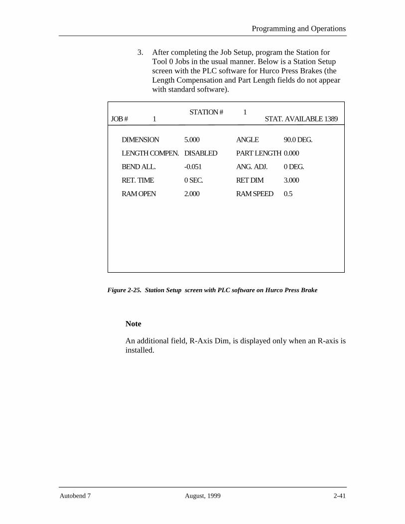
Programming and Operations
Autobend 7 August, 1999 2-41
3. After completing the Job Setup, program the Station forTool 0 Jobs in the usual manner. Below is a Station Setupscreen with the PLC software for Hurco Press Brakes (theLength Compensation and Part Length fields do not appearwith standard software).
JOB # 1STATION # 1
STAT. AVAILABLE 1389
DIMENSION 5.000
LENGTH COMPEN. DISABLED
BEND ALL. -0.051
RET. TIME 0 SEC.
RAM OPEN 2.000
ANGLE 90.0 DEG.
PART LENGTH 0.000
ANG. ADJ. 0 DEG.
RET DIM 3.000
RAM SPEED 0.5
Figure 2-25. Station Setup screen with PLC software on Hurco Press Brake
Note
An additional field, R-Axis Dim, is displayed only when an R-axis isinstalled.

Programming and Operations Manual
2-42 Revision D Hurco
4. Press the Run button. The Need Die Information screenappears. This screen is used for entering the specific dieparameters.
Important
The Die Top field should only be programmed when the correctvalue is known. Otherwise, leave it at 0.000.
JOB # 1034
NEED DIE INFORMATION:
ENTER DIE PARAMETERS:
>>>> OPENING0.500
DIE TOP
Figure 2-26. Need Die Information screen
Note
Opening is displayed only when No is entered for the Program RamDim? field (for angle programming) in Job Setup. An additionalfield, Height, is displayed only when an R-Axis is installed.

Programming and Operations
Autobend 7 August, 1999 2-43
5. After programming these fields, press the Run button andthis screen appears:
SERVOS NOT LATCHED
DEPRESS RUN
Figure 2-27. “Servos Not Latched Depress Run” message
6. Press the Run button and the Tool Calibration screenappears with the cursor at the Die Top field. Refer to the“Calibration” section of the “System Basics” chapter forinformation about calibrating the Tool 0 Job.
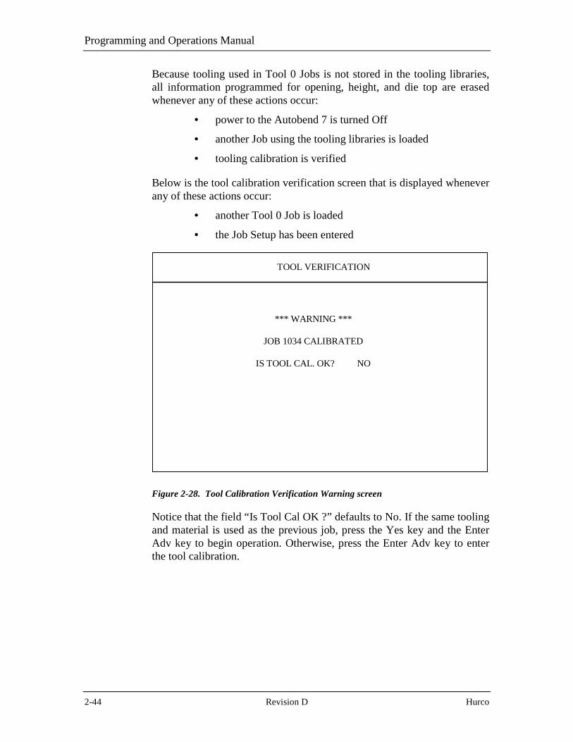
Programming and Operations Manual
2-44 Revision D Hurco
Because tooling used in Tool 0 Jobs is not stored in the tooling libraries,all information programmed for opening, height, and die top are erasedwhenever any of these actions occur:
• power to the Autobend 7 is turned Off
• another Job using the tooling libraries is loaded
• tooling calibration is verified
Below is the tool calibration verification screen that is displayed wheneverany of these actions occur:
• another Tool 0 Job is loaded
• the Job Setup has been entered
*** WARNING ***
JOB 1034 CALIBRATED
IS TOOL CAL. OK? NO
TOOL VERIFICATION
Figure 2-28. Tool Calibration Verification Warning screen
Notice that the field “Is Tool Cal OK ?” defaults to No. If the same toolingand material is used as the previous job, press the Yes key and the EnterAdv key to begin operation. Otherwise, press the Enter Adv key to enterthe tool calibration.

Programming and Operations
Autobend 7 August, 1999 2-45
Selecting the Gauging Surface
The gauge bar provided with the Autobend 7 system provides variousmethods of referencing the material to be formed. For best results do notplace material directly against the gauge bar’s front edge or face. Thissurface should be used to hold the flip fingers and gauge blocks suited tothis task. Ideally using two stops per bend is recommended since toolingcenterlines and material edges are typically not straight.
Figure 2-29. Flip Fingers and Gauge Block
Warning
Ensure that the carriage arrestor bars are correctly seton the gauge(s) to prevent any part of the gauge bar,finger(s), or block(s) from contacting the tooling in anunsafe manner. All adjustments should be made fromthe rear of the press brake. Do not reach across thetooling or in through the bed and ram.

Programming and Operations Manual
2-46 Revision D Hurco
Flip Fingers
Flip fingers permit closer gauge positioning to the tooling. The fingers’tilting action allows reverse bending, with the length of the reverse benddependent on the type of part to be formed.
Fingers can be manufactured by customers to suit their individual formingneeds. For the most accurate results, always reference the flip fingers priorto using them after changing the tooling setup. Refer to the “Referencingthe Gauging Surface” section that follows.
Install the flip fingers at any location along the gauge bar to best suit therequirements of the part. These fingers allow approximately 0.090" ofhorizontal micro-adjustment for close-tolerance forming. Fingers rotate in90° increments for narrow or wide target area selection. Each finger tiltson a leveling adjustment screw at the front bottom of the body. Thelocking screw at the end of the flip finger assembly is used to lock it inplace along the gauge bar.
When two flip fingers are used, both must be set to the same length, asmeasured from the back of the body to the tip of the finger. Otherwise,the parts will not have equal flange lengths on both ends.
Gauge Blocks
Gauge blocks provide a large target area suited for work involving large-scale parts and long flanges.
Install gauge blocks at any location along the gauge bar to best suit therequirements of the part. The locking screw at the end of the gauge blockis used to lock the block in place on the gauge bar. For the most accurateresults, always reference the gauge blocks prior to using them afterchanging the tooling setup. Refer to the “Referencing the GaugingSurface” section that follows.

Programming and Operations
Autobend 7 August, 1999 2-47
Referencing the Gauging Surface
Prior to forming parts, the gauging surface must be referenced to theforming tools. The programmed dimension is the distance from thegauging surface to the punch centerline. This centerline changes for eachset of tooling.
Two zero reference bars are provided with each Autobend 7 to provide aquick and controlled method of squaring the gauge bar. Each zeroreference bar has a 90° “V” notch in the center and a machined edge onone end. The distance from the center of the “V” notch to the machinededge is 5" (127 mm).
Warning
Do not use the reference bars if the rubber pad isdamaged or missing. This pad is a safety feature toreduce the possibility of breakage from slight over-pressure. The pads will not prevent the bars frombreaking in the event of severe over-pressure from thepress brake.
Figure 2-30. Zero Reference bars

Programming and Operations Manual
2-48 Revision D Hurco
Follow these instructions to reference the gauge bar:
1. For systems equipped with Ram control, enter the ModeFunctions screen and toggle the Y-Axis Mode field toStandby Manual. For other systems, proceed as follows:
2. Place the flip fingers or gauge blocks on the gauge bars atthe extreme ends of the tooling to ensure that the gauge baris parallel to the tooling.
3. Loosen the clamp bolts on the lower part of the verticalsupports. Slightly pull back the support.
4. Loosen the carriage arrestor bars.
5. Program a single station job with a 5" (127 mm) dimensionand 0 bend allowance. Refer to the “Job Programming” and“Station Programming” sections for more information.
6. Press the Run button.
7. Insert the zero reference bars so the machined edges face thegauging surface with the “V” notches aligning with thepunch centerline.
8. Carefully jog the ram until the tooling firmly clamps thezero reference bars. Lock the ram in this position.
9. Adjust the gauge bar’s height so the gauging surface isaligned with the reference bars.
Note
For systems equipped with ram control, the Autobend 7 allows offsetprogramming for each punch in memory. This offset is thedifference from the punch tip to the machine centerline.

Programming and Operations
Autobend 7 August, 1999 2-49
10. Push the vertical supports forward so the gauging surface isflush against the zero reference bars. For the most accurateresults, use a 0.002" feeler gauge to verify that the gaugesurface is flush with the machined edge of the zero referencebars.
Figure 2-31. Gauge calibration
11. Lock the clamping bolts at the bottom of the verticalsupports.
12. Return the ram to its open position. Remove the zeroreference bars and store them in a safe place.
13. Press the Stop button on the Autobend 7 console.
14. Return the Y-Axis Mode field to Active.

Programming and Operations Manual
2-50 Revision D Hurco
Setting the Retract at Pinch Sensor
The retract at pinch sensor is used for all Autobend 7 Systems exceptdownacting hydraulic press brakes with ram control, which do not have asensor. Refer to the “Hydraulic Ram Control” section that follows forretract at pinch on ram control.
Upacting Press Brakes
Following are directions for setting the retract at pinch sensor on anupacting press brake:
The field for Retract at Pinch is found in the Configuration Menu. Twochoices are possible, Disable and Enable. Select Enable. Save and Exit theConfiguration Menu.
1. Load the appropriate tooling.
2. Place a sample part across the tooling.
3. Slowly raise the table until the part is firmly pinched in thetooling so that it cannot move. Hold the table in this positionso the sensor can be adjusted.
4. Adjust the coarse setting on the retract sensor to position thesensor above the actuating magnet. The LED should remainOn. If it turns Off, raise the sensor until it turns On.
5. Lower the height of the sensor with the fine adjustmentsetting. Adjust the height until the moment the LED turnsOff.
The sensor is now set for this particular tooling/material combination.Repeat this procedure whenever the tooling or material changes.
Warning
For correct operation of the retract at pinch, the sensormust be positioned so that the gauge begins the retractafter the part is firmly pinched by the tooling. Failure todo so might allow the gauge to retract before the part isfirmly pinched, resulting in the part moving.

Programming and Operations
Autobend 7 August, 1999 2-51
The figure below illustrates the fine and coarse setting adjustments on anupacting press brake:
Figure 2-32. Retract Sensor mounted on an upacting press brake

Programming and Operations Manual
2-52 Revision D Hurco
Downacting Press Brakes
Before setting the retract at pinch sensor on a downacting press brake,enable the Retract at Pinch field in the Configuration Menu screen byselecting Enable. Save and Exit the Configuration Menu. Follow thesedirections for setting the retract at pinch sensor on a downacting pressbrake:
1. Load the appropriate tooling.
2. Place a sample part across the tooling.
3. Slowly jog the ram until the part is firmly pinched in thetooling so it cannot move. Hold the ram in this position sothe sensor can be adjusted.
4. Adjust the coarse setting of the retract sensor to position thesensor below the actuating magnet. The LED should remainOn. If it turns Off, lower the sensor until it turns On.
5. Raise the height of the sensor with the fine adjustmentsetting. Adjust the height until the moment the Led turnsOff.
The sensor is now set for this particular tooling/material combination.Repeat this procedure whenever the tooling or material changes.
Figure 2-33. Retract Sensor mounted on a downacting press brake

Programming and Operations
Autobend 7 August, 1999 2-53
Hydraulic Ram Control
Before setting the retract at pinch on a hydraulic press brake, make theappropriate selection for the Retract at Pinch field on the ConfigurationMenu screen. There are four possible choices: Disable, Linear Scale @5%, 10% and 15%. These percentages represent the amount the punch haspenetrated the material before the gauge begins to retract. The greater thepercentage, the larger the penetration. The retract point can be adjusted forvarious material thickness. To turn Off the Retract at Pinch feature selectDisable. Any retract programmed then occurs only when the ram returnsto the top of stroke.
Follow these directions for setting the retract at pinch:
1. Press the Mode key. The Mode Functions screen appears.
2. Select the Configuration Menu screen.
3. Move the cursor to the Retract at Pinch field.
4. Press the Enter Adv key until Linear Scale @ 15% appears.
5. Move the cursor to the Save and Exit field.
6. Press the Enter Adv key to exit the Configuration Menu.
Warning
Incorrect programming of the retract at pinch or toolinginformation may result in the gauge retracting beforethe material is firmly pinched between the tooling.Always ensure that the programming is correct beforeusing retract at pinch.

Programming and Operations Manual
2-54 Revision D Hurco
Set the percentage at 15% initially and test it. If the gauge retracts too late,the percentage can be lowered until the gauge retracts at the proper time.To test the Retract at Pinch setting, follow these steps:
1. Load the appropriate tooling.
2. Program a job with a retract of 10" (254 mm) and a 5-second delay.
3. Press the Run button.
4. Place a sample part across the tooling.
5. Slowly jog the ram until the part is firmly pinched in thetooling. The gauge should begin to retract immediately asthe material begins to bend.
a. If retract begins before the material is firmlypinched, check the tooling libraries for incorrectinformation.
b. If retract occurs too late, adjust Retract at Pinchsetting and repeat the procedure.
6. Continue to adjust the percentage setting until the gaugeretract is at the correct point.
The setup is correct for this particular tooling/material combination.Repeat this procedure whenever the tooling or material is changed.

Programming and Operations
Autobend 7 August, 1999 2-55
Tool Qualification
Verify programming for tooling using the procedures below to ensure thatthe programmed values are correct. These are the steps to qualify a tool:
1. Verify height.
2. Verify die opening and shoulder radius.
3. Measure die opening.
4. Adjust die opening, if necessary.
5. Measure shoulder radius.
6. Adjust shoulder radius, if necessary.
Hints and tricks
Since it may be difficult to accurately measure the die opening andshoulder radius on frequently used dies, bend several pieces ofmaterial of a known thickness with shallow, medium, and deepbends. Record the angles after each bend.
Verifying Tool Height
To verify tool height, follow these steps:
1. Locate and install the tooling.
2. Locate and measure the sample material.
3. Program a job with the tool(s) to be qualified. Be sure toprogram the measured material thickness.
4. Program a ram dimension of 0 (angle 180°).
5. Press the Run button and insert the sample material.
6. Stroke the ram fully to the depth limit.
7. Verify that the material is only pinched by the tooling andnot bent.
8. Adjust the tool height so the material is only being pinched.
If the material is being bent, increase the tool height. If the material is notmaking contact with the punch, decrease the tool height.

Programming and Operations Manual
2-56 Revision D Hurco
Verifying Die Opening and Shoulder Radius
After completing tool height verification as described in the previoussection, follow these steps to verify the die opening and shoulder radius:
1. Program an angle that the tooling is capable of producing(i.e., 45°, 90°).
2. Form a sample part.
3. Measure the angle.
Important
If the result varies by more than 15° of the programmed value,confirm that the programmed die opening and shoulder radius arecorrect.
Measuring Die Opening
The die opening is measured depending on the software option installed.Outside Shoulder Dimension (OSD) applies to both standard software andto Part Length Compensation (PLC) software for Hurco Press Brakes.Theoretical Sharp Dimension (TSD) applies only to PLC software. TheDie Library List shows which measurement type is used for each die withthe PLC software.
The figure below illustrates the two different points to measure the dieopening:
Figure 2-34. Methods of Measuring the Die Opening

Programming and Operations
Autobend 7 August, 1999 2-57
TSD Measurement
The Hurco Press Brake Tooling Catalog contains the TSD measurementsfor die openings.
Important
Tooling specifications are subject to change without prior notice.
Perform the tool qualification procedure to ensure proper toolingsetup.
To manually measure the die opening to determine TSD, follow thesesteps:
1. Determine the intersection of a line ascending from theinside of the die opening to the top with a line continuingfrom the flat area on the top of the die. (Refer to theprevious figure.)
2. Measure the distance from these intersecting lines on bothsides of the die opening.
The figure below illustrates the points for measuring the TSD die opening:
Figure 2-35. Measuring the TSD Die Opening
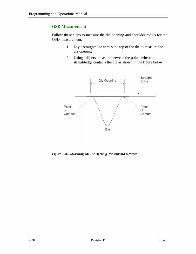
Programming and Operations Manual
2-58 Revision D Hurco
OSD Measurement
Follow these steps to measure the die opening and shoulder radius for theOSD measurement:
1. Lay a straightedge across the top of the die to measure thedie opening.
2. Using calipers, measure between the points where thestraightedge contacts the die as shown in the figure below.
Figure 2-36. Measuring the Die Opening for standard software

Programming and Operations
Autobend 7 August, 1999 2-59
Adjusting the Die Opening
If the bend angles are uniformly opened or closed over the entire range ofbends, the die opening needs to be adjusted. Make adjustments to theprogrammed die opening on the Die Library List screen's Opening field.
• If the actual die opening is larger than the valueprogrammed, the bend angles will be open. Increase the dieopening.
• If the actual die opening is smaller than the valueprogrammed, the bend angle will be closed. Decrease the dieopening.
When adjusting the die opening, use increments no larger than 0.03".Change the die opening and perform another series of bends.
Measuring the Shoulder Radius
Use a radius guide set to measure the die radius. Select the guide that bestfits the shoulder radius and enter the value of that guide.
Since it may be difficult to accurately measure the die opening andshoulder radius on frequently used dies, bend several pieces of material ofa known thickness with shallow, medium, and deep bends. Record theangles after each bend.
Adjusting the Shoulder Radius
If the bend angles are uniformly opened or closed between the shallow andmedium bends, but greater between the medium and deep bends, theshoulder radius needs to be adjusted. Make adjustments to theprogrammed shoulder radius on the Die Library List screen's Radius field.
• If the actual shoulder radius is larger than the valueprogrammed, the bend angles will be closed. Increase theshoulder radius.
• If the actual shoulder radius is smaller than the valueprogrammed, the bend angles will be open. Decrease theshoulder radius
When adjusting the shoulder radius, use increments no larger than 0.02".Change the shoulder radius and perform another series of bends.
Important
Persistent large angle corrections after tool qualification indicate alarge amount of either springback or press brake deflection.

Programming and Operations Manual
2-60 Revision D Hurco
Run Cycle Selection
The Autobend 7 has two run cycles: Auto and Single. Auto operationadvances the stations automatically with each ram stroke, while Singleoperation holds the axes at the station displayed until the Enter Adv key ispressed, then the axes advance to the next programmed station.
Note
For press brakes with optional ram control, refer to the “Y-AxisMode” and “Punch and Die Tool Verification” sections forinformation relative to these options; otherwise, proceed to the“Adjusting Stations and Jobs” section.
Auto Run
Press the Run button to select the Auto Run mode. The axes calibrate andmove to their programmed positions. Upon completion of a ram stroke,the control automatically advances the axes to their next programmedpositions. To stop axes movement, press the Stop button. The axes de-energize and the screen blanks.

Programming and Operations
Autobend 7 August, 1999 2-61
Punch and Die Tool Verification
For systems equipped with optional ram control, when the Run button ispressed, the Tool Verification screen appears to verify that the toolingloaded in the press brake matches the tooling programmed in theAutobend 7 control.
1. Press the Run button.
a. The Tool Verification screen appears. See thesample screen below.
b. Verify that the tooling installed matches the toolingprogrammed before proceeding.
VERIFY TOOLING
PUNCH # 1
DIE # 1
DEPRESS RUN
Figure 2-37. Tool Verification screen
2. If the tooling matches, press the Run button. The axesautomatically calibrate and position to the first station. If thetooling does not match, make the appropriate correctionsand press the Run button.
3. After the axes calibrate, the bending operation may begin.

Programming and Operations Manual
2-62 Revision D Hurco
Adjusting Stations and Jobs
Station information is displayed in double-height characters on the screenand automatically updates as the job advances.
To make station adjustments while in the Auto Run screen, press the Statkey. The Station Setup screen for the station currently displayed appears.To select another station, press the Next key until the desired stationnumber is displayed. To display the Station List screen, press the Stat keyagain.
If job setup or parts count need adjustment while in the Auto Run screen,press the Job key once and the Job Setup screen for the current jobappears. Press it again to display the Job List screen. After making allrequired changes, press the Run button to return to Auto Run Mode.
Here is a single-axis Auto Run screen:
MODE: AUTO
STATION # 1
DIMENSION 5.000
BEND ALL. 0.000
COMPLETED PARTS 0
JOB # 222
Figure 2-38. Single-Axis Auto Run screen
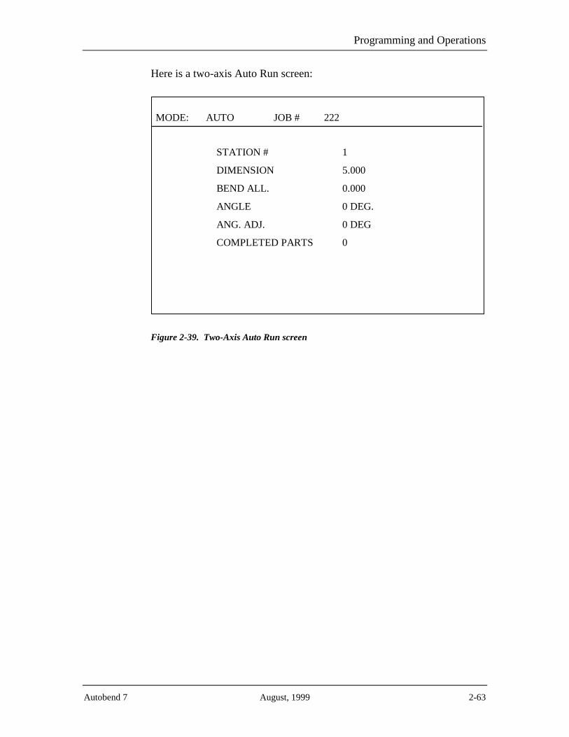
Programming and Operations
Autobend 7 August, 1999 2-63
Here is a two-axis Auto Run screen:
MODE: AUTO
STATION # 1
DIMENSION 5.000
BEND ALL. 0.000
ANGLE 0 DEG.
ANG. ADJ. 0 DEG
COMPLETED PARTS 0
JOB # 222
Figure 2-39. Two-Axis Auto Run screen

Programming and Operations Manual
2-64 Revision D Hurco
Single Run
The Single Run screen provides a method of running only a specificstation in a job. Press the Run button while in the Auto Run mode to selectthe Single Run mode. The axes remain stationary at their current positionuntil the Enter Adv key is pressed. Press the Enter Adv key and the stationdisplayed changes to the next station programmed and the axes advance totheir programmed positions. The station cannot be advanced unless theEnter Adv key is pressed.
To stop the axes’ movement, press the Stop button. The axes de-energizeand the screen blanks.
To return to Auto, press the Run button again.
Note
Retract at pinch is not supported.
The sample screen below is a single-axis Single Run screen:
MODE: SINGLE
STATION # 1
DIMENSION 5.000
BEND ALL. 0.000
COMPLETED PARTS 0
JOB # 222
Figure 2-40. Single-Axis Single Run screen

Programming and Operations
Autobend 7 August, 1999 2-65
The sample screen below is a two-axis Single Run screen:
MODE: SINGLE
STATION # 1
DIMENSION 5.000
BEND ALL. 0.000
ANGLE 0 DEG.
ANG. ADJ. 0 DEG.
COMPLETED PARTS 0
JOB # 222
Figure 2-41. Two-Axis Single Run screen
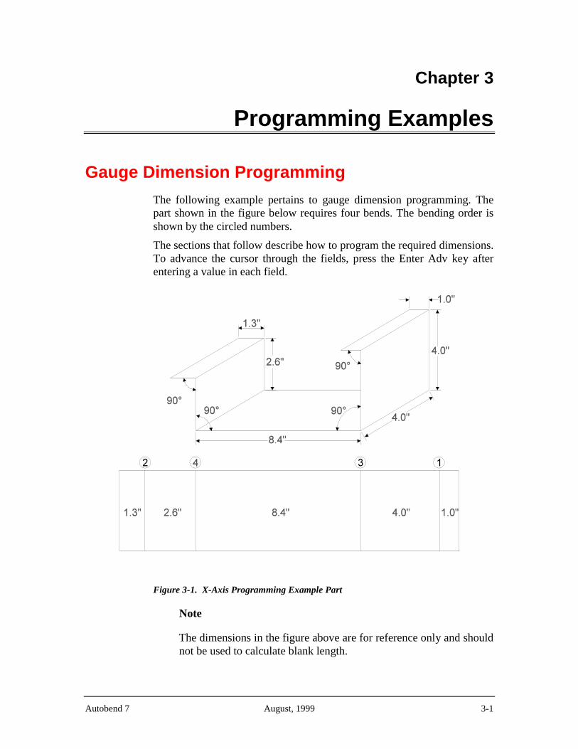
Autobend 7 August, 1999 3-1
Chapter 3
Programming Examples
Gauge Dimension Programming
The following example pertains to gauge dimension programming. Thepart shown in the figure below requires four bends. The bending order isshown by the circled numbers.
The sections that follow describe how to program the required dimensions.To advance the cursor through the fields, press the Enter Adv key afterentering a value in each field.
Figure 3-1. X-Axis Programming Example Part
Note
The dimensions in the figure above are for reference only and shouldnot be used to calculate blank length.

Programming and Operations Manual
3-2 Revision D Hurco
Enter a Job Number
To program the four-bend part for this example, perform the followingprocedures:
1. Press Job. The Job List screen appears.
2. Enter the job’s number (1 2 3 in this example).
JOBS AVAILABLE 500JOB LIST
STAT. AVAILABLE 2000
JOB # COMPLETED PARTS # STN’S
END OF JOB LIST
MAT. THICK
JOB # 123
Figure 3-2. Job List screen
3. Press the Enter Adv key. The Job Setup screen appears.

Programming Examples
Autobend 7 August, 1999 3-3
Program the Job Setup
Follow these steps to program the job setup:
1. Press the Yes key at the Auto Bend All? field.
2. Enter .031 in the Punch Radius field.
3. Enter .06 in the Material field.
4. Leave the value at zero for the Completed Parts field sincethis is a new program.
5. Press the Enter Adv key and the message “JobProgrammed” appears as shown in the screen below,signifying that all the fields have been programmed.
JOBS AVAILABLE 499JOB SETUP
STAT. AVAILABLE 2000
AUTO BEND ALL? YES
MATERIAL 0.060
COMPLETE PARTS 0
PUNCH RADIUS 0.031
JOB PROGRAMMED
Figure 3-3. Job Setup screen
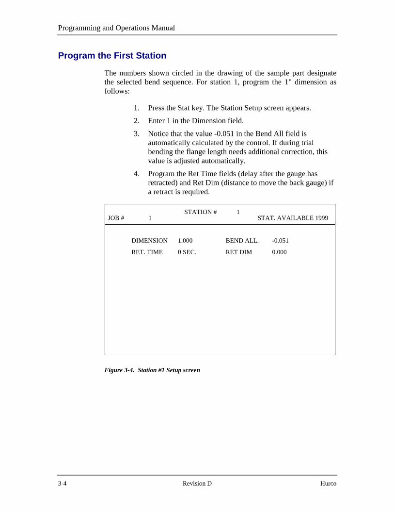
Programming and Operations Manual
3-4 Revision D Hurco
Program the First Station
The numbers shown circled in the drawing of the sample part designatethe selected bend sequence. For station 1, program the 1" dimension asfollows:
1. Press the Stat key. The Station Setup screen appears.
2. Enter 1 in the Dimension field.
3. Notice that the value -0.051 in the Bend All field isautomatically calculated by the control. If during trialbending the flange length needs additional correction, thisvalue is adjusted automatically.
4. Program the Ret Time fields (delay after the gauge hasretracted) and Ret Dim (distance to move the back gauge) ifa retract is required.
JOB # 1STATION # 1
STAT. AVAILABLE 1999
DIMENSION 1.000
RET. TIME 0 SEC.
BEND ALL. -0.051
RET DIM 0.000
Figure 3-4. Station #1 Setup screen

Programming Examples
Autobend 7 August, 1999 3-5
Program the Remaining Stations
Follow these steps to program the remaining stations:
1. Press the New Stat key. The Station #2 Setup screenappears. Notice the values shown for the fields are the sameas those programmed for Station #1.
2. Re-program only entries requiring new values.
3. Enter 1.3 in the Dimension field to change Bend 2’sdimension.
4. Press the New Stat key since the rest of the fields do notrequire new values. The Station Setup screen for Station #3appears.
5. Enter 4 in the Dimension field to change Bend 3’sdimension.
6. Press the New Stat key since the rest of the fields do notrequire new values. The Station Setup screen for Station #4appears.
7. Enter 2.6 in the Dimension field to change Bend 4’sdimension.
8. This last bend requires a retract to allow Bend 2’s flange toclear the gauge.
a. Enter 5 in the Ret Dim field to program a 5"retract.
b. Enter 3 in the Ret Time field to program a 3 seconddelay.
9. The message “Station Programmed” appears in the lowerleft-hand corner of the Station Setup screen.

Programming and Operations Manual
3-6 Revision D Hurco
10. Press the Stat key to display a list of all stations for review.
JOB # 1STATION LIST
STAT. AVAILABLE 1996
STATION #
1
2
3
4
DIMENSION
1.000
1.300
4.000
2.600
BEND ALL.
-0.051
-0.051
-0.051
-0.051
END OF STATION LISTSTATION # 1
Figure 3-5. Station List screen

Programming Examples
Autobend 7 August, 1999 3-7
Before Making a Trial Bend
Follow these steps:
1. Load the correct tooling into the press brake.
2. Select and reference the gauging surface to the tooling asdescribed in the “Selecting the Gauging Surface” and the“Referencing the Gauge Surface” sections in the“Programming and Operations” chapter of this manual.
3. Adjust the ram stroke to achieve the desired angle.
4. Adjust the gauge bar’s height so the material touches thegauging surface.
5. Adjust the Retract at Pinch sensor as described in the“Setting the Retract at Pinch Sensor” section in the“Programming and Operations” chapter of this manual.
Making a Trial Bend and Forming Parts
Follow these steps:
1. Press the Run button twice. The display shows the SingleRun screen. In this mode the control advances the gauge tothe next programmed station when the Enter Adv key ispressed.
2. When the gauge has positioned to the dimension for Station#1, square the material to the gauging surface. Adjust thegauge height if necessary.
3. Stroke the ram to form the flange.
4. Measure the flange.
5. Adjust the Bend All value to achieve the desired flangelength, if necessary. Press the Stat key to return to theStation List screen. Press 1 and the Enter Adv key to editStation #1.
6. If the angles and flange lengths for all the bends are thesame, enter the same Bend All adjustment for the remainingbends.

Programming and Operations Manual
3-8 Revision D Hurco
7. Press the Run button twice and form another flange. Checkand re-adjust if necessary.
8. Press the Enter Adv key to advance the gauge.
9. Form the flange and check the part.
10. Repeat the previous two steps until all flanges are formedcorrectly.
11. Press the Run button one time to enter the Auto Run modewith Station #1 displayed.
12. Form parts.
13. When production is complete, press the Stop button to de-energize the gauge and blank the screen.

Programming Examples
Autobend 7 August, 1999 3-9
X- and Y-Axes Programming Example
This example is for a two-axis system. The axes programmed are the backgauge(s) and ram control. Multiple angles and flanges are programmed inthis example. The part shown in the figure below requires 8 bends to formthe part. Determine the bending sequence before forming this part. Theorder selected for this example is shown by the circled numbers next to theangles.
After determining the bend sequence, program the required dimensions,allowances, and angles for each bend. First program the tooling to formthis part. Depending on the type of press brake additional parameters, ramopening heights, and ram speed change point may also be programmed.Last, program any required retracts.
To advance the cursor through the fields, press the Enter Adv key afterentering values in each field.
The sample screens in this example are from the Optional Part LengthCompensation software.
Figure 3-6. X- and Y-Axes Example Part Bend Sequence
Note
The dimensions in the figure above are for reference only and shouldnot be used to calculate blank length.

Programming and Operations Manual
3-10 Revision D Hurco
Here is an isometric view of this example part:
Figure 3-7. Isometric View of X- and Y-Axes Example Part

Programming Examples
Autobend 7 August, 1999 3-11
Program the Punch
Follow these steps to program the punch:
1. Press the Mode key. The Mode Functions screen appears.
2. Select Punch. The Punch Library screen appears.
3. Press the � key until the cursor appears at punch number 3.
4. Enter .031 in the Radius field.
5. Enter 3.7 in the Height field.
6. Enter 30 in the Angle field.
7. Enter 0 in the Offset field.
Here is the punch described in this example:
Figure 3-8. Punch measurements

Programming and Operations Manual
3-12 Revision D Hurco
Here is a completed Punch Library screen for this example:
PUNCH LIBRARY
NUMBER:
12
>>3456789
1011121314
RADIUS
0.032
0.031
HEIGHT
2.125
3.700
ANGLE
89.0
30.0
OFFSET
0.375
0.000
+, - TO SELECT TOOL | NEXT - NEXT PAGE | CURRENT TOOL # 3<ENTER> TO EDIT | BACK - PREV PAGE | ENTER # __
Figure 3-9. Punch Library screen

Programming Examples
Autobend 7 August, 1999 3-13
Program the Die
Follow these steps to program the die;
1. Press the Mode key. The Mode Functions screen appears.(See the Mode screen figure previously shown in thissection.)
2. Select Die. The Die Library List screen appears.
3. Press the � key until the cursor appears at the die number 3field.
4. Enter .5 in the Opening field.
5. Press 2 in the Height field.
6. Enter 30 in the Angle field.
7. Enter .047 in the Radius field.
8. Enter .6 in the Safety field.
The figure below shows this die’s measurements:
Figure 3-10. Die measurements

Programming and Operations Manual
3-14 Revision D Hurco
Here is a Die Library List screen with the die’s measurementsprogrammed:
DIE LIBRARY LIST
NUMBER:
12
>>>3456789
1011121314
OPENING
0.500
0.500
HEIGHT
4.250
2.000
ANGLE
89.0
30.0
SAFETY
1.000
0.600
+, - TO SELECT TOOL | NEXT - NEXT PAGE | CURRENT TOOL # 3<ENTER> TO EDIT | BACK - PREV PAGE | ENTER # __
RADIUS
0.012
0.047
Figure 3-11. Die Library List screen

Programming Examples
Autobend 7 August, 1999 3-15
Enter a Job Number
Follow these steps to enter a job number:
1. Press the Job key to display the Job List screen.
2. Enter 456 for the Job Number and press the Enter Adv keyto display the Job Setup screen.
JOBS AVAILABLE 499JOB # 456
STAT. AVAILABLE 2000
PROGRAM RAM DIM? NO
PUNCH # 1
MAT. THICK 0.000
DIE # 1
AUTOBEND ALL? NO
COMPLETED PARTS 0
Figure 3-12. Job Setup screen

Programming and Operations Manual
3-16 Revision D Hurco
Program the Job Setup
Follow these steps to program the Job Setup:
1. Press the No key at the Program Ram Dim? Field to selectthe angle format.
2. Enter 3 in the Die # field. This selects die number 3 from thedie library.
3. Enter 3 in the Punch # field. This selects punch number 3from the library.
4. Enter .06 in the Mat Thick field. For best results, alwaysenter the actual measured material thickness.
5. Press the Yes key at the Auto Bend All? field. The controlautomatically calculates bend allowances.
6. Press the Enter Adv key at the Completed Parts field so themessage “Job Programmed” appears at the bottom of thescreen as shown below:
JOBS AVAILABLE 499JOB # 456
STAT. AVAILABLE 2000
PROGRAM RAM DIM? NO
PUNCH # 3
MAT. THICK 0.060
DIE # 3
AUTOBEND ALL? YES
COMPLETED PARTS 0
JOB PROGRAMMED
Figure 3-13. Job Setup screen

Programming Examples
Autobend 7 August, 1999 3-17
Program the First StationThe numbers circled in the drawing for this example designate the selectedbend sequence. For Station #1 the dimension and angle to program are4.00" and 110°.
1. Press the Stat key; the Station #1 Setup screen appears.
2. Enter 4 in the Dimension field.
3. Enter 110 in the Angle field.
4. At the Bend All field, the control has automaticallycalculated a compensation value of -0.051". If furtheradjustment is required, this value will be changedautomatically.
5. Program any angle adjustment required in the Angle Adjfield.
6. Program the Ret Time and Ret Dim fields when a gaugeretract is required. Remember that the retract is selectable soit can occur at either the material pinching point or at ramtop of stroke. This selection is made in the ConfigurationMenu as discussed in that section of the “Programming andOperations” chapter.
7. For downacting hydraulic ram control only, enter 4.3 in theRam Open field, and enter 5 in the Ram Speed field.

Programming and Operations Manual
3-18 Revision D Hurco
Here is the Station #1 screen for this job:
JOB # 1STATION # 1
STAT. AVAILABLE 1999
DIMENSION 4.000
BEND ALL. -0.051
RET. TIME 0 SEC.
RAM OPEN 4.300
ANGLE 110.0 DEG.
ANG. ADJ. 0 DEG.
RET DIM 0.000
RAM SPEED 0.5
Figure 3-14. Station Setup screen

Programming Examples
Autobend 7 August, 1999 3-19
Program the Remaining Stations
Follow these steps to program the remaining stations:
1. Press the New Stat key. The Station #2 Setup screenappears. Notice that all the fields have the same values asthose programmed for Station #1. Only the fields thatrequire new values need to be programmed.
2. Press the New Stat key since no fields require re-programming to complete this bend. The Station #3 Setupscreen appears.
3. Enter 1 in the Dimension field.
4. For downacting hydraulic ram control only: enter 1.5 in theRam Open field.
5. Press the New Stat key since no other fields require re-programming to complete this bend. The Station #4 Setupscreen appears.
6. Press the New Stat key since no fields require re-programming to complete this bend. The Station #5 Setupscreen appears.
7. Enter 90 in the Angle field.
8. Press the New Stat key since no other fields require re-programming to complete this bend. The Station #6 Setupscreen appears.
9. Enter 3 in the Dimension field.
10. Program a retract because a bend flange is referenced at thegauge.
a. Enter 5 in the Ret Dim field and press the EnterAdv key.
b. Enter 2 in the Ret Time field and press the EnterAdv key.
11. For downacting hydraulic ram control only: in the RamOpen field enter 3.5.
12. Press the New Stat key since no other fields require re-programming for this bend. The Station #7 Setup screenappears.
13. Enter 1 in the Dimension field.
14. Enter 0 in the Ret Dim field.

Programming and Operations Manual
3-20 Revision D Hurco
15. Enter 0 in the Ret Time field.
16. For downacting hydraulic ram control only: enter 1.5 in theRam Open field.
17. Press the New Stat key since no other fields require re-programming to complete this part. The Station #8 Setupscreen appears.
18. Enter 3 in the Dimension field.
19. Program a retract because a bend flange is referenced at thegauge.
a. Enter 5 in the Ret Dim field.
b. Enter 2 in the Ret Time field.
20. For downacting hydraulic ram control only: enter 3.5 in theRam Open field.
21. Press the Stat key to list all 8 stations, review informationprogrammed, and correct any errors in programming.

Programming Examples
Autobend 7 August, 1999 3-21
Before Making a Trial Bend
Follow these steps:
1. Load the correct tooling into the press brake.
2. Select and reference the gauging surface to the tooling asdescribed in the “Selecting the Gauging Surface” and“Referencing the Gauge Surface” sections of the“Programming and Operations” chapter.
3. In the Mode Functions screen, set the Y-Axis Mode field toActive by pressing the Stat key until Active appears.
4. Press the Run button. The screen displays the “Verifytooling” message. Confirm that the tooling installed matchesthe tooling programmed before proceeding.
5. Press the Run button. The Y-axis automatically calibrates onupacting and positive stop press brakes. For downactinghydraulic, raise the ram to the top of stroke and then lowerthe ram to calibrate.
6. Adjust the gauge height so the material hits the gaugingsurface.
7. Adjust the Retract at Pinch sensor described in the “Settingthe Retract at Pinch Sensor” or “Setting the Retract at Pinchon Hydraulic Ram Control” sections in the “Programmingand Operations” chapter. For downacting hydraulic ramcontrol, adjust Retract at Pinch as described in the “Start-up” section in the “System Basics” chapter.

Programming and Operations Manual
3-22 Revision D Hurco
Making a Trial Bend and Forming Parts
Follow these steps:
1. Press the Run button twice to display the Single Run screen.The gauge advances to the next programmed station afterthe Enter Adv key is pressed.
2. When the gauge has positioned to the dimension for Station#1, insert the material squarely to the gauging surface.
3. Stroke the ram to form the flange.
4. Measure the flange and angle.
5. Press the Enter Adv key. The gauge advances to Station #2.
6. Insert the material for the second bend. Stroke the ram toform the flange.
7. Measure the flange and angle.
8. Repeat the previous three steps until the part is completelyformed.
9. If corrections are necessary, return to the Station Setupscreens and adjust the Bend All and Angle Adj values toachieve the desired flange lengths and angles.
a. Press the Stat key to return to the Station Listscreen.
b. Press 1 and the Enter Adv key to edit Station #1.
c. Press the Next key to display the next stationscreen.
10. Press the Run button to form another part. Check all flangesand angles; adjust if necessary.
11. Form parts.
12. When production is complete, press the Stop button to de-energize the axes and blank the screen.

Programming Examples
Autobend 7 August, 1999 3-23
X-, Y-, and R-Axes Programming Example
This example is for programming a three-axis system. The axesprogrammed are the back gauge(s), gauge bar height, and ram control.Multiple angles and flanges are programmed in this example. The partshown in the figure below requires six bends to form the part. Determinethe bending sequence before forming this part.
After determining the sequence, program the required dimensions,allowances, retracts and angles for each bend. Example tooling to formthis part will be programmed first. Depending on the type of press brake,additional parameters, e.g., ram opening heights and ram speed changepoints, may also be programmed.
The sample screens in this example are from the Optional Part LengthCompensation software.
Figure 3-15. X-, Y-, and R-Axes Example Part
Note
The dimensions illustrated above are for reference only and shouldnot be used to calculate blank length.

Programming and Operations Manual
3-24 Revision D Hurco
Program the Punch
To program this punch follow these steps:
1. Press the Mode key; the Mode Function screen appears.
2. Select Punch. The Punch Library screen appears.
3. Press the � key until the cursor appears at punch number 3.
4. Enter .031 in the Radius field.
5. Enter 3.75 in the Height field.
6. Enter 30 in the Angle field.
7. Enter 0 in the Offset field.
Here is the punch with the measurements discussed in this example:
Figure 3-16. Punch

Programming Examples
Autobend 7 August, 1999 3-25
Here is the completed Punch Library screen:
PUNCH LIBRARY
NUMBER:
12
>>3456789
1011121314
RADIUS
0.032
0.031
HEIGHT
2.125
3.750
ANGLE
89.0
30.0
OFFSET
0.375
0.000
+, - TO SELECT TOOL | NEXT - NEXT PAGE | CURRENT TOOL # 3<ENTER> TO EDIT | BACK - PREV PAGE | ENTER # __
Figure 3-17. Punch Library screen

Programming and Operations Manual
3-26 Revision D Hurco
Program the Example Die
Follow these steps to program the die:
1. Press the Mode key, and the Mode Functions screenappears. (See the Mode screen figure previously shown inthis section.)
2. Select Die, and the Die Library List screen appears.
3. Press the � key until the cursor appears at die number 3.
4. Enter 5 in the Die Opening field.
5. Enter 2 in the Height field.
6. Enter 30 in the Angle field.
7. Enter .031 in the Radius field.
8. Enter .7 in the Safety field.
Here is a die with the measurements discussed in this example:
Figure 3-18. Die
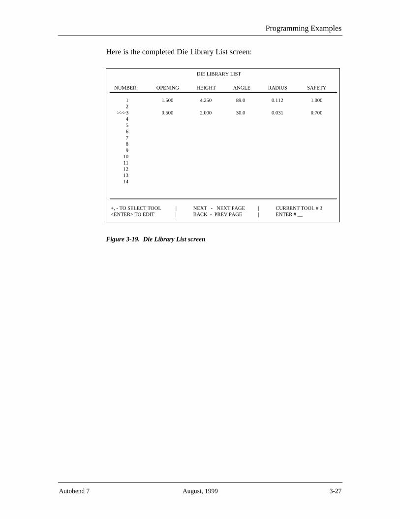
Programming Examples
Autobend 7 August, 1999 3-27
Here is the completed Die Library List screen:
DIE LIBRARY LIST
NUMBER:
12
>>>3456789
1011121314
OPENING
1.500
0.500
HEIGHT
4.250
2.000
ANGLE
89.0
30.0
SAFETY
1.000
0.700
+, - TO SELECT TOOL | NEXT - NEXT PAGE | CURRENT TOOL # 3<ENTER> TO EDIT | BACK - PREV PAGE | ENTER # __
RADIUS
0.112
0.031
Figure 3-19. Die Library List screen

Programming and Operations Manual
3-28 Revision D Hurco
Enter the Job Number
Follow these steps to program the job:
1. Press the Job key to display the Job List screen.
2. Enter 789 for the Job Number.
JOBS AVAILABLE 499JOB LIST
STAT. AVAILABLE 2000
JOB #
1
COMPLETED PARTS
25
# STN’S
2
END OF JOB LIST
MAT. THICK
0.125
JOB # 789
DIE #
1
PUNCH #
1
Figure 3-20. Job List screen
3. Press the Enter Adv key to display the Job Setup screen.

Programming Examples
Autobend 7 August, 1999 3-29
Program the Job Setup
Follow these steps to program this job:
1. Press the Enter Adv key to advance the cursor. At theProgram Ram Dim? field the No does not need to bechanged since angle format is desired.
2. Enter 3 in the Die # field to select example die number 3from the die library.
3. Enter 3 in the Punch # field. This selects example punchnumber 3 from the punch library.
4. Enter .06 in the Material Thickness field. For best results,always enter the actual measured material thickness.
5. Press the Yes key at the Auto Bend All? field. The controlautomatically calculates bend allowances.
6. Press the Enter Adv key at the Completed Parts field so themessage “Job Programmed” appears in the lower left-handcorner of the screen.

Programming and Operations Manual
3-30 Revision D Hurco
Here is the Job Setup screen for job number 789:
JOBS AVAILABLE 499JOB # 789
STAT. AVAILABLE 2000
PROGRAM RAM DIM? NO
PUNCH # 3
MAT. THICK 0.060
DIE # 3
AUTOBEND ALL? YES
COMPLETED PARTS 0
JOB PROGRAMMED
Figure 3-21. Job Setup screen

Programming Examples
Autobend 7 August, 1999 3-31
Program the First Station
The circled numbers in the drawing for this example designate the selectedbend sequence. For Station #1, the dimension and angle to program are 1"and 90°.
1. Press the Stat key, and the Station #1 Setup screen appears.
2. Enter 1 in the Dimension field.
3. Enter 90 in the Angle field.
4. The control automatically calculates the compensation valueof -0.051" at the Bend All field. If further adjustment isrequired, this value will be changed automatically.
5. Any adjustment to the angle of the part is programmed at theAngle Adj field.
6. When a gauge retract is required, program the Ret Dim andRet Time fields. Remember that the retract is selectable sothat it can occur at either the material pinching point or atthe ram’s top of stroke. This selection is made in theConfiguration Menu as discussed in that section in the“Programming and Operations” chapter.
7. For downacting hydraulic ram control only, enter 1.3 in theRam Open field.
8. Enter .5 in the Ram Speed field.
9. Enter 0 in the R-Axis Dim field.

Programming and Operations Manual
3-32 Revision D Hurco
Here is the Station Setup screen with the first station programmed:
JOB # 789STATION # 1
STAT. AVAILABLE 1999
DIMENSION 1.000
BEND ALL. -0.051
RET. TIME 5 SEC.
RAM OPEN 1.300
R-AXIS DIM 0.000
ANGLE 90.0 DEG.
ANG. ADJ. 0 DEG.
RET DIM 3.000
RAM SPEED 0.5
Figure 3-22. Station #1 Setup screen

Programming Examples
Autobend 7 August, 1999 3-33
Program the Remaining Stations
Follow these steps to program the remaining stations:
1. Press the New Stat key; the Station #2 Setup screen appears.Notice that all fields have the same values as thoseprogrammed for Station #1. Only the fields that require newvalues must be re-programmed.
2. Enter 5 in the Dimension field.
3. Enter 4.5 in the Ram Open field.
4. Enter .5 in the R-Axis Dim field. This raises the gaugesurface 0.5" above the die.
5. Press the New Stat key since no other fields require re-programming for this bend, and the Station #3 Setup screenappears.
6. Enter 1 in the Dimension field.
7. Enter 135 in the Angle field.
8. For downacting hydraulic ram control only, enter 4.3 in theRam Open field.
9. Enter .5 and press the - key in the R-Axis Dim field. Thislowers the gauging surface 0.5" below the die.
10. Press the New Stat key since no other fields require re-programming for this bend. The Station #4 Setup screenappears.
11. Enter 90 in the Angle field.
12. For downacting hydraulic ram control only, enter 1 in theRam Open field.
a. Enter 0 in the R-Axis Dim field.
b. Since no other fields require re-programming forthis bend, press the New Stat key. The Station #5Setup screen appears.
13. Enter 135 in the Angle field.
14. Enter .5 and press the - key in the R-Axis Dim field.

Programming and Operations Manual
3-34 Revision D Hurco
15. Since no other fields require re-programming for this bend,press the New Stat key. The Station #6 Setup screenappears.
16. Enter 10 in the Dimension field.
17. Enter 90 in the Angle field.
18. For downacting hydraulic ram control only, enter 4.5 in theRam Open field.
19. Enter 1 in the R-Axis Dim field. This raises the gaugingsurface 1" above the die.
20. Press the Stat key to list all 6 stations as shown in thesample screen below. Review all the information on thescreen and correct any errors that may have been madeduring programming.
JOB # 789STATION LIST
STAT. AVAILABLE 1994
STATION #
1
2
3
4
5
6
DIMENSION
1.000
5.000
1.000
1.000
1.000
10.000
BEND ALL.
-0.051
-0.051
-0.018
-0.051
-0.018
-0.051
END OF STATION LIST
STATION # 1
ANGLE
90
90
135
90
135
90
ANGLE ADJ.
0.000
0.000
0.000
0.000
0.000
0.000
Figure 3-23. Station List screen

Programming Examples
Autobend 7 August, 1999 3-35
Before Making a Trial Bend
Follow these steps:
1. Load the correct tooling into the press brake.
2. Select and reference the gauging surface to the tooling asdescribed in the “Selecting the Gauging Surface” and the“Referencing the Gauge Surface” sections in the“Programming and Operations” chapter.
3. On the Mode Functions screen, set the Y-Axis Mode field toActive. Press 9 until Active appears.
4. Press the Run button. The screen displays the “VerifyTooling” message. Confirm that the tooling matches thetooling programmed before proceeding.
5. Press the Run button. The Y-axis calibrates on upacting andpositive stop press brakes. For downacting hydraulic pressbrakes, raise the ram to the top of stroke and then lower theram.
6. Adjust the gauge height so the material hits the gaugingsurface.
7. Adjust the Retract at Pinch sensor as described in the“Setting the Retract at Pinch Sensor” section in the“Programming and Operations” chapter.
8. For downacting hydraulic ram controls, adjust the Retract atPinch as described in “Setting the Retract at Pinch onHydraulic Ram Control” section in the “Programming andOperations” chapter.
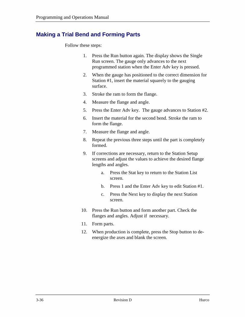
Programming and Operations Manual
3-36 Revision D Hurco
Making a Trial Bend and Forming Parts
Follow these steps:
1. Press the Run button again. The display shows the SingleRun screen. The gauge only advances to the nextprogrammed station when the Enter Adv key is pressed.
2. When the gauge has positioned to the correct dimension forStation #1, insert the material squarely to the gaugingsurface.
3. Stroke the ram to form the flange.
4. Measure the flange and angle.
5. Press the Enter Adv key. The gauge advances to Station #2.
6. Insert the material for the second bend. Stroke the ram toform the flange.
7. Measure the flange and angle.
8. Repeat the previous three steps until the part is completelyformed.
9. If corrections are necessary, return to the Station Setupscreens and adjust the values to achieve the desired flangelengths and angles.
a. Press the Stat key to return to the Station Listscreen.
b. Press 1 and the Enter Adv key to edit Station #1.
c. Press the Next key to display the next Stationscreen.
10. Press the Run button and form another part. Check theflanges and angles. Adjust if necessary.
11. Form parts.
12. When production is complete, press the Stop button to de-energize the axes and blank the screen.

Autobend 7 May, 1999 4-1
Chapter 4
Communication Port
The RS-232-C serial communication port is a standard feature on theAutobend 7 control system (AB7).
Optional RS-232-C Serial Port
The RS-232-C serial port provides uploading or downloading of the entirememory block between the AB7 control and a personal computer. For bestresults, be familiar with the following information concerning location,connector types, cables, and pins before operating the system with thisoption.
Port Location
RS-232-C connection to the AB7 is located on the power cabinet. Connectthe port to a computer to download or upload files.
Connector Types
Since the communications industry standard for connectors has changedover the years, Hurco has adapted its controls to incorporate thesechanges. The RS-232-C serial port on the Hurco control uses a 9-pin D-type connector.
A 9-pin D-type connector (DB-9) is illustrated in the figure that followsthis section. Refer to the table on the following page for additionalinformation pertaining to DB-9 serial port connections.
Note
While the signals listed in the table on the following page conform tothe RS-232-C standard, it should be noted that not all standard RS-232-C signals are available at this port. Some peripheral devices mayhave provisions for RS-232-C control signals not available at theports described here. However, such devices can usually be adaptedto these ports. In some cases, it may be necessary to add jumpers tothe connector for the peripheral device.

Programming and Operations Manual
4-2 Revision C Hurco
9-Pin D-Type Port Specifications
The table below shows pin signal definitions for the 9-pin port. The figureon the following page illustrates the pin assignments of the 9-pin port inthe AB7 power cabinet. The RS-232-C DB-9 connector in the AB7 iswired as a DTE device. When using a PC with a DB-9 connector, wire thecable using the diagram shown in the 9-pin to 9-pin Cable Connectionsfigure at the end of this chapter. Typically, the RTS and CTS pins are notused.
RS-232-C Signals Available at 9-Pin Serial Ports
Pin 1 - DCD This pin connection is not used by the machine control.
Pin 2 - RXD(Receive Data)
Data received by the control in serial format from peripheraldevice on this line.
Pin 3 - TXD(Transmit Data)
Data transmitted by the control to peripheral device in serialformat on this line.
Pin 4 - DTR(Data Terminal Ready)
This pin connection is not used by the machine control.
Pin 5 - SG(Signal Ground)
Line establishing the common ground reference potential forall interface.
Pin 6 - DSR(Data Set Ready)
This pin connection is not used by the machine control.
Pin 7 - RTS(Request-to-Send)
This pin connection is not used by the machine control.
Pin 8 - CTS(Clear-to-Send)
This pin connection is not used by the machine control.
Pin 9 - RI(Ring Indicator)
This pin connection is not used by the machine control.
Note
Consult the manual of the peripheral device being connected to theAutobend control and determine whether it is a Data TerminalEquipment (DTE) or Data Communication Equipment (DCE)device. Different connections are used between DTE and DCEdevices. All Autobend controls are considered DTE devices.

Communication Port
Autobend 7 May, 1999 4-3
Pin Assignments
The figure below illustrates the pin assignments of the 9-pin port in theAB7 power cabinet:
Figure 4-1. Male 9-Pin D-Type (DB-9) Connector
Cable Recommendations
Follow these cable recommendations:
1. Use double-shielded low capacitance cable designed for thispurpose.
2. Use six-conductor cable for connectors.
3. Use 22-gauge stranded wire, minimum size.
4. Do not use cable lengths over 100 feet.
5. Connect cable shield(s) only to the PG pin (protective/frameground) at the Hurco machine. Do not connect shield(s) tothe opposite end of cable (peripheral device).
6. Route cables away from fluorescent lighting fixtures orother possible sources of electrical noise (i.e., power cables,contactors, transformers, arc welders, etc.).

Programming and Operations Manual
4-4 Revision C Hurco
Cable Diagrams
The cable configuration diagrams define the required connections betweenthe AB7 and IBM or compatible PC. Refer to the 25-pin to 9-pin and the9-pin to 9-pin figures that follow. Note that all cables use the TXD, RXD,and SG signals, and only those computers that use hardware handshakingrequire the additional RTS and CTS signals.
Note
If a standard cable is purchased, it can be inter-connected with a nullmodem.
25-Pin to 9-Pin Cable Diagram
Follow the cable diagram below when making a cable to connect an AB7to a computer (25-pin port).
Note
Connect CTS and RTS signals if using CTS/RTS Protocol.
Figure 4-2. 25-pin to 9-pin Cable Connections

Communication Port
Autobend 7 May, 1999 4-5
9-Pin to 9-Pin Cable Diagrams
Follow the cable diagrams in the figures below when making a cable toconnect an AB7 control to a computer (9-pin port) or to another AB7control. There are two options for RTS and CTS connections with 9-pinto 9-pin cables:
Figure 4-3. 9-pin to 9-pin Cable Connections
Figure 4-4. 9-pin to 9-pin Cable Connections
Note
Connect CTS and RTS signals if using CTS/RTS Protocol.

Programming and Operations Manual
4-6 Revision C Hurco
Cable Configurations
Because of the variety of connectors used at the PC and the Autobend(AB) control, there are several cable configurations. These cables followthe standard RS-232-C wiring configuration. Make or buy the cable tomatch the configuration.
25-Pin to 9-Pin Cable Configuration
PC, 25-Pin Connector AB, 9-Pin Connector
Signal Pin Pin Signal
Transmit Data (TX) 2 2 Receive Data (RX)
Receive Data (RX) 3 3 Transmit Data (TX)
Clear To Send (CTS) 5 7 Request To Send (RTS)
Signal Ground (GND) 7 5 Signal Ground (GND)
Request To Send (RTS) 4 8 Clear To Send (CTS)
Shield 7 (Shield not connected)

Communication Port
Autobend 7 May, 1999 4-7
9-Pin to 9-Pin Cable Configuration(RTS to CTS Option 1)
PC, 9-Pin Connector AB, 9-Pin Connector
Signal Pin Pin Signal
Transmit Data (TX) 3 2 Receive Data (RX)
Receive Data (RX) 2 3 Transmit Data (TX)
Clear To Send (CTS)Jumpered to PC 7
8 Request To Send (RTS)(Not connected)
Signal Ground (GND) 5 5 Signal Ground (GND)
Request To Send (RTS)Jumpered to PC 8
7 Clear To Send (CTS)(Not connected)
Shield 5 (Shield not connected)
9-Pin to 9-Pin Cable Configuration(RTS to CTS Option 2)
PC, 9-Pin Connector AB, 9-Pin Connector
Signal Pin Pin Signal
Transmit Data (TX) 3 2 Receive Data (RX)
Receive Data (RX) 2 3 Transmit Data (TX)
Clear To Send (CTS) 8 7 Request To Send (RTS)
Signal Ground (GND) 5 5 Signal Ground (GND)
Request To Send (RTS) 7 8 Clear To Send (CTS)
Shield 5 (Shield not connected)

Programming and Operations Manual
4-8 Revision C Hurco

Autobend 7 August, 1999 5-1
Chapter 5
Troubleshooting
This chapter provides information about hardware, application, andtooling diagnostics for troubleshooting, screen messages, and a glossary ofterms. Refer to this chapter to help determine solutions to problems shouldthey occur.
Troubleshooting Guide
Here is a guide to follow while troubleshooting.
Warning
Turn Off the power whenever possible duringtroubleshooting. Use extreme caution when working inor around equipment that is powered.
Review these procedures and questions to evaluate the problem:
Procedures Questions
1. Recognize symptoms. • What is really wrong?
2. Elaborate symptoms. • How is the problem apparent?
3. List probable faulty functions. • Is it always that way?
4. Localize the faulty function. • If intermittent, under what conditions?
5. Localize trouble to the circuit. • Was there any abuse? (heat, vibration,contamination, etc.)
6. Perform failure analysis. • Did the problem occur suddenly orgradually?
• Did the problem occur during operation?
• Does the problem affect other functions?
• Any additional details?
• Has anyone tried to fix it? If so, how?

Programming and Operations Manual
5-2 Revision D Hurco
Hardware Diagnostics
The following table lists possible difficulties and procedures to follow tocorrect each one:
Problem Possible Cause Correction
No consoledisplay or partialconsole display.
Incoming power not turned on. Turn power on.
Power not applied according tovoltage tag.
Correct per voltage tag.
Incoming power fuse blown. Replace fuses.
Control cable not correctlyplugged into the connector onthe Mainboard located in thepower cabinet or to the ConsoleInterface board.
Correct if wrong.
Power Supply is defective. If the CRT is fluctuating orlooks like it is “breathing,”check for ±10% of 12 volts onthe power supply. Also, checkfor the following voltages atthese Mainboard test points:TP2 for +5 VDC ± 10%TP3 for +12 VDC ± 10%TP4 for -12 VDC ± 10%(Use TP1 for GroundReference.) Replace ifnecessary.
Display/CRT is defective. Select an existing program inthe control and run it. If thegauge functions, the CRT isdefective.
If gauge does not function,unplug display/CRT and re-runprogram. If the gauge nowworks, display/CRT isdefective.
Mainboard is defective. Check the Mainboard to seethat the Run LED is on. If not,replace Mainboard.

Troubleshooting
Autobend 7 August, 1999 5-3
Problem Possible Cause Correction
When Run ispressed, thegauge does notmove.
“Motion error”fault may also bedisplayed.
Servo control relay, K1 isnot being energized on theMainboard.
Check the servo enable signal onthe Mainboard at connector J4 pin12. If not present, check that K1relay circuit on the Mainboard isenergizing. If not, replaceMainboard.
Gauge cable is damaged. Inspect and replace if damaged.
The motor is damaged. Check for damage by:
1. disconnecting power to theAutobend power cabinet
2. using DVM (Ohmmeter) forohms.
3. checking motor contacts forohm reading. Rotate every 20 to30°. Look for similar readings.
4. looking for inconsistentmeasurements and replacingMTE.
5. using DVM on low (20 VDC)scale.
6. placing leads on motor contactsand manually moving thecarriage. A 2-3 VDC readingshould be measured (dependingon carriage speed). If not,replace motor.
Continued on next page.

Programming and Operations Manual
5-4 Revision D Hurco
Continued from previous page.
Problem Possible Cause Correction
When Run ispressed, thegauge does notmove.
“Motion error”fault may also bedisplayed. (Continued)
Servo amplifier damaged. 1. Check for 45 to 65 VDC at theservo amplifier. If not, checkfusing and connections.
2. Check for servo enable input.When servo enable is active,input should be low. Tracesignal back to Mainboard. Ifsignal is not present, replaceMainboard.
3. Check for limit switch input.When switches are not actuated,input should be low. Trace inputto switches then to motionmodule, replace if necessary.
If these steps have been tried andeverything checks out OK, replacethe drive amplifier.
DAC signal not present atamplifier due to damagedmotion module or cable.
Trace signal to motion module. Ifnot found, replace motion module.

Troubleshooting
Autobend 7 August, 1999 5-5
Problem Possible Cause Correction
Control display isLocking-up
Incoming power source isincorrect
Ensure incoming power source is athree-wire system (hot, neutral,and ground) and that the voltagerate is correct for the unit on adedicated line for the Autobend.Correct if not.
Power supply is defective. Check test points on mainboard.
• TP2 for +5VDC ±10%
• TP3 for +12VDC ±10%
• TP4 for -12VDC ±10%
If voltages are missing, checkpower supply outputs.
Gauge movesonly when Runbutton is pressed.
Defective latching relay K1on the Mainboard.
Check for cold solder jointsaround the relay. If none arefound, replace the Mainboard.
Defective Run or Stopbuttons.
Check the continuity of the Runand Stop keys. Replace ifdefective.

Programming and Operations Manual
5-6 Revision D Hurco
Problem Possible Cause Correction
Gauge drifts outof position oroscillates.
Balance pot on servo amplifierneeds adjustment.
Adjust if necessary.
Motor needs cleaned. Remove the motor, check thebrushes, and clean carbon fromthe motor. Re-balance pot onservo amplifier.
Defective Encoder. Check encoder signals. Replaceif necessary.
Servo amp defective. If problem remains, replaceservo amp.
Gauge notpositioningcorrectly.
Defective Encoder. Check encoder signals. Replaceif necessary.
Cables damaged or connectionsloose.
Check cables for damage.Replace if necessary. Tightenany loose connections.
Drive belt loose or damaged. Check drive belt. Make sure it istightened properly and is notworn. Replace or tighten ifnecessary.
Mechanical binding or drag. Check linear ways andleadscrew for obstructions.Replace worn parts if necessary.
Calibration incorrect. If, after calibration, the gaugepositions ¼" off, re-position themarker pulse in relationship withthe calibration switch. Loosenthe drive belt and turn motorpulley (without moving theleadscrew pulley) approximately¼ - ½ turn; tighten belt.

Troubleshooting
Autobend 7 August, 1999 5-7
Problem Cause Correction
Duringcalibration, thegauge moves tothe rear and stays.
Calibration switch orcable is damaged or loose.
Complete a continuity check of theswitch with the cable unplugged.Replace if damaged. Check continuityof the cable. Replace if damaged.Tighten any loose connections.
Motion module isdefective.
Check for proper outputs from themotion module. If not, replace themotion module board.
Servo amplifier isdamaged.
Check for valid enable signals. Ifpresent, replace servo amplifier.
The Run cycle isinterrupted ordoes not occur.One of thefollowing errormessages isdisplayed:
Dimension error. The back gauge has a programmeddimension greater than 24". Check theprogram to be sure it is correct.
Missing encoder counts ormissing marker pulse.
Check encoder signals. Replace ifnecessary.
Motion error. 1. Check gauge travel for binding.Repair if necessary.
2. Check for 45 to 65 VDC at theservo amplifier. Replace fuse orpower supply if not present.
3. Check for enable signals atamplifier. Replace motion moduleor Mainboard if not present.
4. If above checks out, replace servoamplifier.
Keyboard doesnot function.
Keyboard is damaged. Check keyboard per the keyboard testprocedure outlined in the KeyboardTest Chart that follows this section.Check all the keys in question. Ifdefective, replace the keyboard. If thekeyboard passes, replace theMainboard.
Check keyboard wiring.

Programming and Operations Manual
5-8 Revision D Hurco
Keyboard Test
Follow these steps to test the keyboard:
1. Disconnect the keyboard connector J7 at the ControlConsole Connection Board.
2. With an ohmmeter, measure across the pins on J7, verifyingthe operation of each key according to the chart. As eachkey is depressed the meter should read 0 ohms, and as eachkey is released the meter should read infinite ohms.
1. Mode 8. Stat. 15. N/A 22. Job
2. #1 9. #4 16. #7 23. decimal(.)
3. #2 10. #5 17. #8 24. #0
4. #3 11. #6 18. #9 25. Clear
5. Yes 12. No 19. Insert 26. Delete
6. Next 13. Out 20. N/A 27. In
7. Enter Adv. 14. Back 21. N/A 28. New Stat
Figure 5-1. Keyboard Test Chart

Troubleshooting
Autobend 7 August, 1999 5-9
Application and Tooling Diagnostics
Problem Cause Correction
Angleprogrammed isnot obtained with<10° of correction
Wrong tooling (die opening, dieradius, punch radius, etc.)programmed.
Check that the toolinginstalled is the same asspecified in the Job Setupscreen for the active job.
Verify measurements andcorrect if necessary.
Material thickness varies Check material being useddoes not vary from blank-to-blank.
Verify measurements andcorrect if necessary.
Tooling not appropriate foroperation.
Check that tooling installed isappropriate.
Verify measurements andcorrect if necessary.
Tooling in poor condition orinstalled incorrectly.
Check that the tooling is ingood condition and properlyinstalled.
Ram tilt not level. Form parts on each end ofmachine. Level machine.
Inadequate die crowing. Shim tooling to obtainconsistent angle along bendlength.
Press brake control switchesimproperly set.
Verify that press brakecontrol switches are set sothey cannot be actuated (whenY-axis is Active). Try othersettings for Ram Speedselection, Stop, On, SpeedChange, etc., to improve pressbrake reliability. Refer to thepress brake manufacturer’smanual for instructions.
Insufficient stroke length. Raise the open height of theram by increasing the RamOpen parameter.

Programming and Operations Manual
5-10 Revision D Hurco
Screen Messages
There are two types of screen messages. One type of message verifiesprogramming and operation functions. Error messages alert the operator ofpotential problems. The system can still be operated normally under theseconditions. Error messages are cleared by pressing the Stop button.
Programming andOperation Messages Definition
Are You Sure Question used to qualify a previous response, allowingan operator to be certain that the selections are correct.
Auto Run cycle that advances the stations automatically witheach ram stroke.
Calibrating Message to indicate that gauge(s) are establishing anelectronic reference position, prior to operation.
Do not confuse this with referencing the gauge bar.
Cleared Indicates selected input was erased from the systemmemory.
Deleted Indicates selected job or station was removed from thesystem’s memory.
Depress Run Message for operator to enable axes.
End of Job List Indicates the last job available in the system memory.
End of Station List Indicates the last station available in the selected job.
Manual Jog Method to manually move the axes.
New Job Notification that a new job number was created.
No Job Programmed Indicates no jobs exist in memory.
No Stat Programmed Indicates no stations exist in memory for the jobselected.
Not Available Indicates there is not enough memory available tocontinue programming.
Not Found Indicates a non-existent job or station requested.
Protected Access Programming disabled; the control’s keyswitch lockedin Operation Only mode and unable to acceptprogramming.

Troubleshooting
Autobend 7 August, 1999 5-11
Programming andOperation Messages
(continued) Definition
Servos Not Latched Indicates that the servo relay did not latch.
Single Run cycle that holds the axes at the station displayeduntil the Enter Adv key is pressed. Then the axesadvance to the next programmed station.
Station Programmed Indicates the completion of programming for thecurrent station.
Uncalibrated Indicates operation is selected and the axes have notbeen calibrated.
Verify Tooling Confirms tooling loaded in program is actually thetooling used.
Error Messages Definition
Amplifier Fault An error signal from the amplifier shows that theamplifier is not operational.
Configuration Error The system setup is not correct.
Dimension Error Programmed dimension exceeds maximum travel limits.
Entry Error Improper data input or command.
Dim + Tool Height > Max The ram dimension and tool height exceeds the Ymaximum parameter.
Dimension < Tool Safety The gauge dimension is less than the safety programmedin the die library.
IO Task Indicates that an I/O command is incorrect. Indicates apotential hardware problem. Contact Hurco.
Illegal Angle Angle is below minimum (die/punch library).
Illegal Depth Stop The Depth Stop number is not 1 through 6.
Illegal Die Top The Tool 0 calibration is incorrect.
Illegal Die Bottom The Tool 0 calibration is incorrect.
Illegal Ram Open The value programmed for Ram Open is not between 0and the Y-maximum value.
Illegal Ram Stroke The ram was stroked while the other axes were stillpositioning.

Programming and Operations Manual
5-12 Revision D Hurco
Error Messages(continued) Definition
Illegal Speed Change The value programmed for Speed Change is notbetween 0 and the Y-maximum value.
Illegal State Specifies the type of I/O task error. Contact Hurco.
Invalid Entry Improper selection or command.
Invalid Message Command to change states is incorrect. Contact Hurco.
Job Not Fully Programmed The job programming is not complete.
Keystroke TerminationError
An error created because of a possible hardwareproblem.
Limit Switch Reports an unexpected limit switch operation duringoperation.
Marker Not Found The electronic pulse from the encoder was not detectedduring calibration.
Missing Cal Switch Displayed when the limit switch input is not detectedduring calibration.
Missing Limit Switch Displayed when the limit switch input is not detectedduring calibration.
Missing Encoder Counts The electronic pulses from the encoder are not detected.
Missing Marker Displayed when the electronic calibration signal was notdetected during calibration.
Motion Error Axis movement has occurred incorrectly or not at all.
Net Gauge Dimension The sum of the gauge parameters (dimension, bendallowance, retract dimension) exceed the maximumdimension limit.
Punch Angle > Die Angle Angle of punch is greater than the die’s angle.
Run Task Indicates that an operation command was not handledproperly.
Warning: Low Battery Message displayed at power up indicating battery islow.

Troubleshooting
Autobend 7 August, 1999 5-13
Glossary
Angle The desired programmed bend of a part, measured as an insideangle. Used when equipped with ram control.
Axis The term used to describe the system’s control of the gauge (X-axis), ram (Y-axis), and gauge height (R-axis).
Bend Allowance Programmable offset to the gauge position that compensates formaterial growth or shrinkage due to bending. Can be manuallyentered or calculated automatically by the control.
Configuration Menu The system setup screen used to configure the control for thespecific axes.
Cursor The flashing line or arrows on the screen that indicate the dataentry point.
Dimension The programmed position of the gauging surface.
Flash EPROM Memory storage device.
Job Number Numerical sequence of up to 17 digits that identifies the jobsprogrammed.
Jobs Available The number of new jobs that may be programmed. Afterprogramming a new job, this number decreases by one.
Manual Jog Provides a method to manually move the axes.
Master Clear Erases the entire memory.
Master Save Stores the entire memory in Flash EPROM.
Measurement Units Global selection of inch or metric measurement.
Mode Functions The screen that allows auxiliary functions to be performed.
Outside ShoulderDimension (OSD)
The tangent point between the die radius and the top of the dieused for measuring die opening.
Part LengthCompensationSoftware
Software offered with the Hurco Press Brake that handles PartLength Compensation. With Part Length Compensation, thelength of the part is programmed by the software to compensatefor angle adjustment on longer parts. This software includes afield for selecting the type of metal used.
Pinch Point The point of operation where the part is firmly clamped by thepress brake’s tooling.
Programming The process of entering data in the Autobend 7 control.
Protected Access A keyswitch lock disables programming when switched Off.
R-Axis Describes the control of the gauge bar’s height.
Ram Control The ability to control the press brake’s ram stroke position.Referred to as second-axis control and Y-axis.
Ram Dimension The programmed depth of the punch into the die.Continued on next page.

Programming and Operations Manual
5-14 Revision D Hurco
Continued from previous page.
Ram Open The position of the punch above the die at the completion of thebend.
Ram Speed The position where the punch changes speeds.
Read Program Transfers an entire memory block from a personal computer to theAutobend 7 via the RS-232-C port.
Retract Dimension The programmed gauge(s) movement away from the press brake’stooling. Activated either at the pinch point of the tooling or at thetop of stroke.
Retract Delay The programmed timer delay when the gauge has retracted. Thetimer begins when the ram has returned to the top of stroke. Aftercompletion of the delay the gauge(s) move to the nextprogrammed dimension.
Second Axis The term used to control the press brake’s ram positions. Referredto as ram control and Y-axis.
SerialCommunications
Provides the uploading/downloading of the entire memory blockof the Autobend 7 and a personal computer via the RS-232-C port.
Station A bend programmed within a job.
Stations Available The number of new stations that can be programmed into thesystem. Programming a new station decreases this number.
Theoretical SharpDimension (TSD)
The measurement between the inside of the shoulder radii used formeasuring die opening. The Hurco Press Brake Tooling Catalogcontains the TSD measurements for die openings.
Write Program Transfers an entire memory block from the Autobend 7 to apersonal computer via the RS-232-C port.
X-Axis The term used to describe the control of the gauge.
Y-Axis The term used to describe the control of the press brake’s ram.Also referred to as ram control and second axis.

Index
Autobend 7 August, 1999 I-1
AActive, 2-16Amplifier Fault message, 5-11Angle, 2-12, 2-14, 2-30, 5-13Angle Adj, 2-30Application diagnostics, 5-9Are You Sure? message, 2-7, 5-10Audible beeper, 2-10Auto Bend All.?, 2-23Auto message, 5-10Auto run cycle, 2-60
job setup adjustments, 2-62parts count adjustments, 2-62station adjustments, 2-62
Auto Run screensingle axis, 2-62two axis, 2-63
Autobend 7 Gauges, 1-4Autobend power cabinet, 1-3Automatic Bend Allowance, 2-23Automatic calculation
bend allowance, 2-29Axes, 5-13
orientation, 1-5R-axis, 1-5X-axis, 1-5Y-axis, 1-5
Axis Calibration screen, 2-5
BBack - Prev Page message, 2-18Back key, 1-24Baud rate, 2-6, 2-10Bend All, 2-29Bend Allowance, 5-13
CCable
configuration, 4-4recommendations, 4-3specifications, 4-4
Calibrating message, 5-10Calibration, 1-26
downacting hydraulic, 1-26ram, 1-28status, 2-5Tool 0, 1-29, 2-38upacting linear scale, 1-27
Calibration switchmotor rotation, 2-5proper spacing, 2-5
Carriage arrestor bars, 1-12, 2-45Caution tape, 1-9Clear key, 1-24Cleared message, 5-10Communication direction, 2-6Completed Parts, 2-20, 2-23Configuration Error message, 5-11Configuration Menu screen, 2-9, 5-13Console keys, 1-24
•, 1-24Back, 1-24Clear, 1-24Delete, 1-24Emergency Stop, 1-15Enter Adv, 1-24In, 1-24Insert, 1-24Job, 1-24Mode, 1-24New Stat, 1-24Next, 1-24No -, 1-24number pad, 1-24Out, 1-24Run button, 1-15Stat, 1-24Yes +, 1-24
Programming and Operations Manual
I-2 Revision D Hurco
Control console, 1-3, 1-23keys, 1-23maintenance schedule, 1-22membrane keys, 1-24Protect keyswitch, 1-23, 1-25Run button, 1-23, 1-25Stop button, 1-2, 1-23, 1-25
Cursor, 5-13
DDelete
all jobs, 2-25single job, 2-25station, 2-36
Delete key, 1-24, 2-36Deleted message, 5-10Depress Run message, 5-10Depth Stop, 2-33Die
angle, 2-14delete, 2-15height, 2-14measurement, 2-13, 2-15, 2-56number, 2-24opening, 2-14programming, 2-13radius, 2-14return to die number, 2-15safety, 2-15Tool 0, 2-38
Die Bottom Tool 0, 2-38Die opening verification, 2-56Die Top Tool 0, 2-38Dim + Tool Height > Max message,
5-11Dimension, 2-29, 5-13Dimension < Tool Safety, 5-11Dimension Error message, 5-11Downacting hydraulic
calibration, 1-26
EElectrical
grounding point, 1-18printed circuit boards, 1-18static, 1-18systems, 1-16
Emergency stop circuits, 1-12Encoder marker pulse position, 2-5End of Job List message, 5-10End of Station message, 5-10Entry Error message, 5-11EPROM, 2-8Erasing programs, 2-7Error Limit Switch, Axis message, 5-12Error Missing Cal Switch message, 5-12Error Missing Marker message, 5-12Error Motion Error, Axis message, 5-12Exit without Saving, 2-10
FFire hazards, 1-19Fixturing, 1-14
safety, 1-14Flange length, 2-29Flash EPROM, 2-8, 5-13Flip fingers, 1-12, 2-46Foreseeable misuse, 1-6
from operator error, 1-6machine modification, 1-7tampering with safety devices, 1-7unattended operation, 1-15
GGauge
blocks, 2-46height, 2-5, 2-33
Gauge barlength, 1-4referencing, 2-48
Gauge movementretract position, 2-29
Gauging surface, 2-45flip fingers, 2-46gauge blocks, 2-46referencing, 2-47zero reference bars, 2-47

Index
Autobend 7 August, 1999 I-3
HHardware diagnostics, 5-2Height, 2-12, 2-14
Tool 0, 2-38Horizontal adjustment, 1-4Hydraulic
downacting calibration, 1-26
IIllegal Angle message, 5-11Illegal Depth Stop message, 5-11Illegal Die Bottom message, 5-11Illegal Die Top message, 5-11Illegal message, 5-12Illegal Ram Open message, 5-11Illegal Ram Stroke message, 5-11Illegal Speed Change message, 5-12Illegal State message, 5-12In key, 1-24Insert key, 1-24, 2-36Insert station, 2-36Invalid Entry message, 5-12IO Task message, 5-11
JJob key, 1-24, 2-17Job List screen, 2-17
single axis, 2-18two axis, 2-19
Job Not Fully Programmed message,5-12
Job number, 5-13maximum digits, 2-18Quick Job Setup, 2-37Station Dimensions, 2-37
Job Programmed message, 2-22Job Programming, 2-17Job Setup screen, 2-21
single axis, 2-21two axis, 2-22
Jobsavailable, 2-18, 5-13current station list, 2-34programmed, 2-18
job number, 2-18parameters, 2-18
Jog, 2-16
KKeyboard test, 5-8Keypad, 1-23Keystroke Termination Error message,
5-12
LLanguage type, 2-10Length Compensation, 2-31Limit switches, 1-14Linear scale
Part Length Compensation, 2-31upacting calibration, 1-27
Linear Scale @ 10%, 2-53Linear Scale @ 15%, 2-53Linear Scale @ 5%, 2-53
MMaintenance schedule, 1-21
control console, 1-22R-axis, 1-21X-axis, 1-21Y-axis, 1-21, 1-22
Manual Jog, 5-13Manual Jog message, 5-10Manual Jog screen, 2-4Marker Not Found message, 5-12Marker pulse
outside acceptable range, 2-5proper spacing, 2-5
Master Clear screen, 2-7, 5-13Master Save screen, 2-8, 5-13Mat. Thick.?, 2-20, 2-23Measurement units, 2-10, 5-13Memory
transfer from PC, 2-6transfer to PC, 2-6
Messages, 2-28, 5-10Amplifier Fault, 5-11Are You Sure?, 2-7, 5-10Auto, 5-10Back - Prev Page, 2-18, 2-34Calibrating, 5-10
Programming and Operations Manual
I-4 Revision D Hurco
Messages (continued)Cleared, 5-10Configuration Error, 5-11Deleted, 5-10Depress Run, 5-10Dim + Tool Height > Max, 5-11Dimension < Tool Safety, 5-11Dimension Error, 5-11End of Job List, 5-10End of Station, 5-10Entry Error, 5-11Error Limit Switch, Axis, 5-12Error Missing Cal Switch, 5-12Error Missing Marker, 5-12Error Motion Error, Axis, 5-12Illegal Angle, 5-11Illegal Depth Stop, 5-11Illegal Die Bottom, 5-11Illegal Die Top, 5-11Illegal Ram Open, 5-11Illegal Ram Stroke, 5-11Illegal Speed Change, 5-12Illegal State, 5-12Invalid Entry, 5-12Invalid Message, 5-12IO Task, 5-11Job Not Fully Programmed, 5-12Job Programmed, 2-22Keystroke Termination Error, 5-12Manual Jog, 5-10Marker Not Found, 5-12Missing Encoder Counts, 5-12Missing Limit Switch, 5-12Move Ram to T.O.S., 1-31Net Gauge Dimension, 5-12New Job, 5-10Next - Next Page, 2-18, 2-34No Job Programmed, 5-10No Stat Programmed, 2-28, 5-10Not Available, 5-10Not Found, 5-10Protected Access, 5-10Punch Angle > Die Angle, 5-12Reading, 2-6Run Task, 5-12
Messages (continued)Saving Part Programs, 2-8Servos Not Energized Depress Run,
2-43Servos Not Latched, 5-11Single, 5-11Station Programmed, 5-11Uncalibrated, 5-11Verify Tooling, 5-11Warning Low Battery, 5-12Writing, 2-6
Missing Encoder Counts message, 5-12Mode Functions screen, 2-16, 5-13
single axis, 2-2two axis, 2-3
Mode key, 1-24Mode of operation, 2-10Move Ram to T.O.S. message, 1-31
NNeed Die Information screen, 2-42Net Gauge Dimension message, 5-12New Job message, 5-10New Stat key, 1-24, 2-26Next - Next Page message, 2-18Next key, 1-24No - key, 1-24No Job Programmed message, 5-10No Stat Programmed message, 2-28,
5-10Not Available message, 5-10Not Found message, 5-10Number
die, 2-14punch, 2-12
Number pad, 1-24
OOffset, 2-12Offset calculation, 2-23Opening, 2-14
Tool 0, 2-38

Index
Autobend 7 August, 1999 I-5
Operator, 1-11appropriate apparel, 1-11error, 1-6personal care, 1-11qualifications, 1-6training, 1-11
Out key, 1-24Outside shoulder dimension (OSD),
2-56, 2-58
PPart bending
safety, 1-15Part Length, 2-31Part Length Compensation, 2-31
Die Measurement Point, 2-15die programming, 2-13linear scale, 2-31measuring die opening and shoulder
radius, 2-56Pinch point, 2-29, 5-13Pinch retract, 2-50PLC, 2-13, 2-15, 2-31, 2-56Power cabinet
location, 1-3safety decals, 1-10
Power connection, 1-16Press brake, 1-3
electro-mechanical failures, 1-16emergency stop circuits, 1-12foreseeable misuse, 1-6owner responsibilities, 1-6unattended operation, 1-15
Program Ram Dim?, 2-24Programming, 5-13Programming examples, 3-1
gauge dimension, 3-1X- and Y-axes, 3-9
Die Library List screen, 3-14die programming, 3-13example part, 3-9forming parts, 3-22isometric example part, 3-10Job Setup screen, 3-15, 3-16Punch Library screen, 3-12punch programming, 3-11
Programmign ExamplesX- and Y-axes (continued)
station programming, 3-17, 3-19Station Setup screen, 3-18trial bend, 3-21, 3-22
X-, Y-, and R-axes, 3-23Die Library List screen, 3-27die programming, 3-26example part, 3-23forming parts, 3-36Job List screen, 3-28job setup, 3-29Job Setup screen, 3-30Punch Library screen, 3-25punch programming, 3-24Station List screen, 3-34station programming, 3-31, 3-33Station Setup screen, 3-32trial bend, 3-35, 3-36
X-axisexample part, 3-1forming parts, 3-7job setup, 3-3Job Setup screen, 3-3Station List screen, 3-4, 3-6station programming, 3-4, 3-5trial bend, 3-7
Programming examples, 3-1Protect keyswitch, 1-23, 1-25, 2-2Protected Access, 5-13Protected Access message, 5-10Punch
angle, 2-12delete, 2-12height, 2-12number, 2-24offset, 2-12radius, 2-12, 2-23return to punch number, 2-12Tool 0, 2-38
Punch Angle > Die Angle message, 5-12Punch Radius, 2-23
Tool 0, 2-38

Programming and Operations Manual
I-6 Revision D Hurco
QQuick Job Setup, 2-37
RRadius, 2-12, 2-14Ram calibration rotary vane press
brakes, 1-28Ram control, 2-33, 5-13
Angle mode, 2-24bottom stop position, 2-30, 2-33correction value, 2-30die, 2-11opening height, 2-31, 2-32Ram Dimension mode, 2-24slow down position, 2-31, 2-32stopping point, 2-20, 2-23tool verification, 2-61
Ram Dim, 2-30Ram dimension, 5-13Ram Open, 2-31, 2-32, 5-14Ram Speed, 2-31, 2-32, 5-14R-axis, 1-5, 5-13
maintenance schedule, 1-21zero position, 2-33
R-Axis Dim, 2-33Read Program message, 5-14Reading message, 2-6Re-calibration, 1-32, 2-5Referencing
gauge bar, 2-48gauging surface, 2-47zero reference bars, 2-47
Ret Dim, 2-29, 5-14Ret Time, 2-29, 5-14Retract at pinch, 2-10, 2-50
coarse setting, 2-51, 2-52downacting press brakes, 2-52fine setting, 2-51, 2-52hydraulic ram control, 2-53
Disable, 2-53Linear Scale @ 10%, 2-53Linear Scale @ 15%, 2-53Linear Scale @ 5%, 2-53
sensor, 2-50setting, 2-50upacting press brakes, 2-50
Rotary vane press brakes, 1-28RS-232-C Serial port, 4-1Run button, 1-15, 1-23, 1-25Run cycle
Auto, 2-60Single, 2-60
Run Task message, 5-12
SS6 gauge, 1-4S7 gauge, 1-4S8 gauges, 1-4Safety, 1-6, 2-15
additional sources, 1-19Autobend system, 1-1carriage arrestor bars, 1-12emergency stop circuits, 1-12external power source, 1-13fire prevention, 1-6, 1-19fixturing, 1-14gauge bar, 1-12gauging fingers, 1-12glasses, 1-11grounding point, 1-18hardware/software, 1-7limit switches, 1-14operator training, 1-11owner responsibilities, 1-6press brake, 1-1, 1-12printed circuit boards, 1-18proper apparel, 1-11ram, 1-12sign, 1-9static, 1-18subsystem failure, 1-16travel limits, 1-14while operating press brake, 1-15while running program, 1-15
Safety decals, 1-9, 1-10, 1-11caution tape, 1-9warning sign, 1-9
Save and Exit, 2-10Saving Part Programs message, 2-8Saving programs, 2-8

Index
Autobend 7 August, 1999 I-7
ScreensAuto Run, 2-60Axis Calibration, 2-5Configuration Menu, 2-9Die Library, 2-13Job List, 2-17Job Programming, 2-17Job Setuo, 2-17Manual Jog, 2-4Master Clear, 2-7Master Save, 2-8Mode Functions, 2-2, 2-16Need Die Information, 2-42Punch Library, 2-11Serial Communications, 2-6Single Run, 2-64Station List, 2-34Station Programming, 2-26Station Setup, 2-26Tool 0 Job List, 2-39, 2-40Tool 0 Station Setup, 2-41Tool Calibration Verification, 2-44
Second axis, 5-14Serial communications, 5-14
read program to PC, 2-6write program to PC, 2-6
Serial Communications screen, 2-6Serial port, 4-1
9-pin D-type, 4-2cable recommendations, 4-3cable specifications, 4-4, 4-5connector types, 4-1location, 4-1pin assignments, 9-pin D-type, 4-3specifications, 4-2
Servicedepartment, 1-20gauge performance, 1-20lack of power, 1-20preparation for call, 1-10, 1-20safety decals, 1-10screen errors, 1-20
Servos Not Energized Depress Runmessage, 2-43
Servos Not Latched message, 5-11
Shoulder radius verification, 2-56Shut-down, 1-33
block ram, 1-33flash EPROM, 1-33Master Save, 1-33
Single Axis Quick Job Setup, 2-37Single message, 5-11Single Run screen
single axis, 2-64two axis, 2-65
Standby Manual, 2-16Start-up, 1-32Start-up screen, 2-10Stat key, 1-24, 2-26Station, 5-14
advance automatically, 2-60available count, 2-34, 5-14delete, 2-36hold axes, 2-60insert, 2-36parameters, 2-26
Station List screensingle axis, 2-34two axis, 2-35
Station Programmed message, 2-28,5-11
Station Programming, 2-26Station Setup screen
single axis, 2-27Stop button, 1-23, 1-25
TTheoretical sharp dimension (TSD),
2-56, 2-57Tool 0 Job List screen, 2-39, 2-41Tool 0 Job Setup screen, 2-40Tool 0 jobs
die, 2-38erased, 2-44programming, 2-38, 2-39punch, 2-38
Tool Calibration Verification screen2-44
Tool height verification, 2-55Tool qualification, 2-55

Programming and Operations Manual
I-8 Revision D Hurco
Tooling diagnostics, 5-9Top of stroke, 2-29Troubleshooting, 5-1
application diagnostics, 5-9hardware diagnostics, 5-2keyboard test, 5-8tooling diagnostics, 5-9
UUnattended operation, 1-15Uncalibrated message, 5-11Upacting linear scale
calibration, 1-27
VVerify
die opening, 2-56shoulder radius, 2-56
Verify tool height, 2-55Verify Tooling message, 5-11Vertical supports, 2-49
WWarning sign, 1-9Write Program message, 5-14Writing message, 2-6
XX-axis, 1-5, 5-14
maintenance schedule, 1-21
YY-axis, 1-5, 5-14
Active, 2-16Jog, 2-16maintenance schedule, 1-21, 1-22mode, 2-16Standby Manual, 2-16
Yes + key, 1-24Zero reference bars, 2-47