programmable dc power suppliesa g r e a t e r m e a s u r e o f c o n f i d e n c e series 2200...
TRANSCRIPT

ECNEDIFNOCFOERUSAEMRETAERGA
Series 2200Programmable DC Power SuppliesReference Manual2200S-901-01 Rev. A / November 2011
Test Equipment Depot - 800.517.8431 - 99 Washington Street Melrose, MA 02176 - TestEquipmentDepot.com

Programmable DC Power Supplies
Reference Manual
© 2011, Keithley Instruments, Inc.
Cleveland, Ohio, U.S.A.
All rights reserved.
Any unauthorized reproduction, photocopy, or use the information herein, in whole or in part, without the prior written approval of Keithley Instruments, Inc. is strictly prohibited.
All Keithley Instruments product names are trademarks or registered trademarks of Keithley Instruments, Inc. Other brand names are trademarks or registered trademarks of their respective
holders.
Document number: 2200S-901-01 Rev. A / November 2011
Series 2200

11/07
Safety Precautions The following safety precautions should be observed before using this product and any associated instrumentation. Although some instruments and accessories would normally be used with nonhazardous voltages, there are situations where hazardous conditions may be present.
This product is intended for use by qualified personnel who recognize shock hazards and are familiar with the safety precautions required to avoid possible injury. Read and follow all installation, operation, and maintenance information carefully before using the product. Refer to the user documentation for complete product specifications.
If the product is used in a manner not specified, the protection provided by the product warranty may be impaired.
The types of product users are:
Responsible body is the individual or group responsible for the use and maintenance of equipment, for ensuring that the equipment is operated within its specifications and operating limits, and for ensuring that operators are adequately trained.
Operators use the product for its intended function. They must be trained in electrical safety procedures and proper use of the instrument. They must be protected from electric shock and contact with hazardous live circuits.
Maintenance personnel perform routine procedures on the product to keep it operating properly, for example, setting the line voltage or replacing consumable materials. Maintenance procedures are described in the user documentation. The procedures explicitly state if the operator may perform them. Otherwise, they should be performed only by service personnel.
Service personnel are trained to work on live circuits, perform safe installations, and repair products. Only properly trained service personnel may perform installation and service procedures.
Keithley Instruments products are designed for use with electrical signals that are rated Measurement Category I and Measurement Category II, as described in the International Electrotechnical Commission (IEC) Standard IEC 60664. Most measurement, control, and data I/O signals are Measurement Category I and must not be directly connected to mains voltage or to voltage sources with high transient over-voltages. Measurement Category II connections require protection for high transient over-voltages often associated with local AC mains connections. Assume all measurement, control, and data I/O connections are for connection to Category I sources unless otherwise marked or described in the user documentation.
Exercise extreme caution when a shock hazard is present. Lethal voltage may be present on cable connector jacks or test fixtures. The American National Standards Institute (ANSI) states that a shock hazard exists when voltage levels greater than 30 V RMS, 42.4 V peak, or 60 VDC are present. A good safety practice is to expect that hazardous voltage is present in any unknown circuit before measuring.
Operators of this product must be protected from electric shock at all times. The responsible body must ensure that operators are prevented access and/or insulated from every connection point. In some cases, connections must be exposed to potential human contact. Product operators in these circumstances must be trained to protect themselves from the risk of electric shock. If the circuit is capable of operating at or above 1000V, no conductive part of the circuit may be exposed.
Do not connect switching cards directly to unlimited power circuits. They are intended to be used with impedance-limited sources. NEVER connect switching cards directly to AC mains. When connecting sources to switching cards, install protective devices to limit fault current and voltage to the card.
Before operating an instrument, ensure that the line cord is connected to a properly-grounded power receptacle. Inspect the connecting cables, test leads, and jumpers for possible wear, cracks, or breaks before each use.
When installing equipment where access to the main power cord is restricted, such as rack mounting, a separate main input power disconnect device must be provided in close proximity to the equipment and within easy reach of the operator.
For maximum safety, do not touch the product, test cables, or any other instruments while power is applied to the circuit under test. ALWAYS remove power from the entire test system and discharge any capacitors before: connecting or disconnecting cables or jumpers, installing or removing switching cards, or making internal changes, such as installing or removing jumpers.
Do not touch any object that could provide a current path to the common side of the circuit under test or power line (earth) ground. Always make measurements with dry hands while standing on a dry, insulated surface capable of withstanding the voltage being measured.
The instrument and accessories must be used in accordance with its specifications and operating instructions, or the safety of the equipment may be impaired.

11/07
Do not exceed the maximum signal levels of the instruments and accessories, as defined in the specifications and operating information, and as shown on the instrument or test fixture panels, or switching card.
When fuses are used in a product, replace with the same type and rating for continued protection against fire hazard.
Chassis connections must only be used as shield connections for measuring circuits, NOT as safety earth ground connections.
If you are using a test fixture, keep the lid closed while power is applied to the device under test. Safe operation requires the use of a lid interlock.
If a screw is present, connect it to safety earth ground using the wire recommended in the user documentation.
The symbol on an instrument means caution, risk of danger. The user should refer to the operating instructions located in the user documentation in all cases where the symbol is marked on the instrument.
The symbol on an instrument means caution, risk of electric shock. Use standard safety precautions to avoid personal contact with these voltages.
The symbol on an instrument shows that the surface may be hot. Avoid personal contact to prevent burns.
The symbol indicates a connection terminal to the equipment frame.
If this symbol is on a product, it indicates that mercury is present in the display lamp. Please note that the lamp must be properly disposed of according to federal, state, and local laws.
The WARNING heading in the user documentation explains dangers that might result in personal injury or death. Always read the associated information very carefully before performing the indicated procedure.
The CAUTION heading in the user documentation explains hazards that could damage the instrument. Such damage may invalidate the warranty.
Instrumentation and accessories shall not be connected to humans.
Before performing any maintenance, disconnect the line cord and all test cables.
To maintain protection from electric shock and fire, replacement components in mains circuits — including the power transformer, test leads, and input jacks — must be purchased from Keithley Instruments. Standard fuses with applicable national safety approvals may be used if the rating and type are the same. Other components that are not safety-related may be purchased from other suppliers as long as they are equivalent to the original component (note that selected parts should be purchased only through Keithley Instruments to maintain accuracy and functionality of the product). If you are unsure about the applicability of a replacement component, call a Keithley Instruments office for information.
To clean an instrument, use a damp cloth or mild, water-based cleaner. Clean the exterior of the instrument only. Do not apply cleaner directly to the instrument or allow liquids to enter or spill on the instrument. Products that consist of a circuit board with no case or chassis (e.g., a data acquisition board for installation into a computer) should never require cleaning if handled according to instructions. If the board becomes contaminated and operation is affected, the board should be returned to the factory for proper cleaning/servicing.

Introduction ............................................................................................................... 1-1
Welcome .............................................................................................................................. 1-1
Extended warranty ............................................................................................................... 1-1
Contact information .............................................................................................................. 1-1
CD-ROM contents ................................................................................................................ 1-2
Key features ......................................................................................................................... 1-2
Standard accessories ........................................................................................................... 1-2
Optional accessories ............................................................................................................ 1-3
Services available ................................................................................................................ 1-3
Specifications ....................................................................................................................... 1-3 Electrical ratings for the power connection ................................................................................ 1-4 Environmental performance ...................................................................................................... 1-4 Nominal voltage ratings ............................................................................................................. 1-4 Float voltage rating .................................................................................................................... 1-4
General operation ..................................................................................................... 2-1
Operating requirements ....................................................................................................... 2-1
Installing the system ............................................................................................................. 2-3 Power the instrument on and off ............................................................................................... 2-3 Check the output ....................................................................................................................... 2-3
Operating basics .................................................................................................................. 2-5 Front panel at a glance ............................................................................................................. 2-5 Rear panel at a glance ............................................................................................................ 2-13 110 V/220 V selector switch .................................................................................................... 2-15 Front panel operation .............................................................................................................. 2-15 Rear panel operation ............................................................................................................... 2-26
Operation examples ........................................................................................................... 2-29 Saving setups example ........................................................................................................... 2-29 Timer example ........................................................................................................................ 2-30 List mode example .................................................................................................................. 2-31
Default setup ...................................................................................................................... 2-34
Clear and sanitize procedures ........................................................................................... 2-34 Terms ...................................................................................................................................... 2-35 Memory devices ...................................................................................................................... 2-36 Data export devices ................................................................................................................ 2-37
Remote operation ..................................................................................................... 3-1
Section overview .................................................................................................................. 3-1
Communication interfaces.................................................................................................... 3-1 Using the USB ........................................................................................................................... 3-1 Using the GPIB ......................................................................................................................... 3-2 Command timing ....................................................................................................................... 3-2
Command syntax ................................................................................................................. 3-3
Table of Contents

Table of Contents Series 2200 Programmable DC Power Supplies Reference Manual
ii 2200S-901-01 Rev. A/November 2011
Command and query structure .................................................................................................. 3-4 Command entry ......................................................................................................................... 3-5
Command groups ................................................................................................................. 3-9
Command reference ................................................................................................. 4-1
Commands listed in alphabetical order ................................................................................ 4-2
*CLS (no query form) ........................................................................................................... 4-2
CONFigure:SOUNd[:STATe] ............................................................................................... 4-3
*ESE ..................................................................................................................................... 4-3
*ESR? (query only) .............................................................................................................. 4-4
FETCh:CURRent[:DC]? (query only) ................................................................................... 4-4
FETCh:VOLTage[:DC]? (query only) ................................................................................... 4-5
FETCh[:SCALar]:POWer? (query only) ............................................................................... 4-5
*IDN? (query only) ................................................................................................................ 4-6
MEASure:CURRent[:DC]? (query only) ............................................................................... 4-6
MEASure:VOLTage[:DC]? (query only) ............................................................................... 4-7
*OPC .................................................................................................................................... 4-7
*PSC..................................................................................................................................... 4-8
*RCL (no query form) ........................................................................................................... 4-9
*RST (no query form) ........................................................................................................... 4-9
*SAV (no query form) ......................................................................................................... 4-10
[SOURce:]CURRent[:LEVel] .............................................................................................. 4-10
[SOURce:]DIGital:DATA .................................................................................................... 4-11
[SOURce:]DIGital:FUNCtion .............................................................................................. 4-12
[SOURce:]FUNCtion:MODE .............................................................................................. 4-13
[SOURce:]LIST:COUNt ...................................................................................................... 4-13
[SOURce:]LIST:CURRent[:LEVel] ..................................................................................... 4-14
[SOURce:]LIST:MODE ....................................................................................................... 4-15
[SOURce:]LIST:RCL (no query form) ................................................................................ 4-15
[SOURce:]LIST:SAVe (no query form) .............................................................................. 4-16
[SOURce:]LIST:STEP ........................................................................................................ 4-16
[SOURce:]LIST:VOLTage[:LEVel] ..................................................................................... 4-17
[SOURce:]LIST:WIDth ....................................................................................................... 4-18
[SOURce:]OUTPut:DFI:SOURce ....................................................................................... 4-19
[SOURce:]OUTPut:PON[:STATe] ...................................................................................... 4-20
[SOURce:]OUTPut:PROTection:CLEar (no query form) ................................................... 4-20
[SOURce:]OUTPut:RI:MODE ............................................................................................ 4-21

Series 2200 Programmable DC Power Supplies Reference Manual Table of Contents
2200S-901-01 Rev. A/November 2011 iii
[SOURce:]OUTPut[:STATe] ............................................................................................... 4-22
[SOURce:]OUTPut:TIMer:DELay ....................................................................................... 4-23
[SOURce:]OUTPut:TIMer[:STATe] .................................................................................... 4-24
[SOURce:]VOLTage[:LEVel] .............................................................................................. 4-25
[SOURce:]VOLTage:PROTection[:LEVel] ......................................................................... 4-26
[SOURce:]VOLTage:PROTection:STATe.......................................................................... 4-27
[SOURce:]VOLTage:RANGe ............................................................................................. 4-28
*SRE................................................................................................................................... 4-29
STATus:OPERation:CONDition? (query only) ................................................................... 4-29
STATus:OPERation:ENABle ............................................................................................. 4-30
STATus:OPERation[:EVENt]? (query only) ....................................................................... 4-31
STATus:QUEStionable:CONDition? (query only) .............................................................. 4-31
STATus:QUEStionable:ENABle ......................................................................................... 4-32
STATus:QUEStionable[:EVENt]? (query only) .................................................................. 4-33
STATus:QUEStionable:NTRansition ................................................................................. 4-34
STATus:QUEStionable:PTRansition .................................................................................. 4-35
*STB? (query only) ............................................................................................................. 4-36
SYSTem:ERRor? (query only) ........................................................................................... 4-36
SYSTem:KEY ..................................................................................................................... 4-37
SYSTem:LOCal (no query form) ........................................................................................ 4-38
SYSTem:POSetup ............................................................................................................. 4-38
SYSTem:REMote (no query form) ..................................................................................... 4-39
SYSTem:RWLock (no query form) .................................................................................... 4-39
SYSTem:VERSion? (query only) ....................................................................................... 4-39
*TRG (no query form) ......................................................................................................... 4-40
TRIGger[:IMMediate] (no query form) ................................................................................ 4-40
TRIGger:SOURce .............................................................................................................. 4-41
*TST? (query only) ............................................................................................................. 4-41
*WAI (no query form) ......................................................................................................... 4-42
Programming examples ..................................................................................................... 4-42 Example 1 ............................................................................................................................... 4-43 Example 2 ............................................................................................................................... 4-45 Example 3 ............................................................................................................................... 4-45 Example 4 ............................................................................................................................... 4-46
Troubleshooting guide ............................................................................................. 5-1
What to do if the power supply does not turn on ................................................................. 5-1

Table of Contents Series 2200 Programmable DC Power Supplies Reference Manual
iv 2200S-901-01 Rev. A/November 2011
Next Steps ................................................................................................................. 6-1
Additional Series 2200 information ...................................................................................... 6-1
Maintenance .............................................................................................................. A-1
Cleaning ............................................................................................................................... A-1
Calibration ................................................................................................................. B-1
Performance verification ...................................................................................................... B-1 Test record ................................................................................................................................ B-2 DC voltage accuracy with remote sense ................................................................................... B-3 DC voltage accuracy without remote sense .............................................................................. B-4 DC voltage readback accuracy ................................................................................................. B-5 DC voltage line regulation ......................................................................................................... B-6 DC voltage load regulation ........................................................................................................ B-6 DC overvoltage detection .......................................................................................................... B-6 DC current accuracy ................................................................................................................. B-7 DC current readback accuracy .................................................................................................. B-8 DC current line regulation.......................................................................................................... B-9 DC current load regulation ........................................................................................................ B-9 Voltage noise at 7 MHz ........................................................................................................... B-10 Voltage noise at 20 MHz ......................................................................................................... B-10 Current noise at 20 MHz ......................................................................................................... B-10
Performance verification procedures ................................................................................. B-11 Performance verification conditions ........................................................................................ B-11 Equipment required ................................................................................................................. B-11 Test equipment ....................................................................................................................... B-12 Self test ................................................................................................................................... B-13 Check DC voltage accuracy with remote sense ...................................................................... B-14 Check DC voltage accuracy without remote sense and voltage readback accuracy ............... B-17 Check DC voltage line regulation ............................................................................................ B-19 Check DC voltage load regulation ........................................................................................... B-21 Check DC overvoltage detection ............................................................................................. B-23 Check DC current and DC current readback accuracy ........................................................... B-25 Check DC current line regulation ............................................................................................ B-27 Check DC current load regulation ........................................................................................... B-29 Check voltage noise (7 MHz) .................................................................................................. B-31 Check voltage noise (20 MHz) ................................................................................................ B-33 Check current noise ................................................................................................................ B-35
Status model ............................................................................................................. C-1
Status and events ................................................................................................................ C-1
Status reporting structure ..................................................................................................... C-1
Registers .............................................................................................................................. C-3 Status registers ......................................................................................................................... C-3 Enable registers ........................................................................................................................ C-7 Queues ..................................................................................................................................... C-8 Messages and codes ................................................................................................................ C-9
Display character codes ........................................................................................... D-1
ASCII code chart .................................................................................................................. D-2

Series 2200 Programmable DC Power Supplies Reference Manual Table of Contents
2200S-901-01 Rev. A/November 2011 v
Index ........................................................................................................................... I-1


In this section:
Welcome .................................................................................. 1-1 Extended warranty ................................................................... 1-1 Contact information .................................................................. 1-1 CD-ROM contents .................................................................... 1-2 Key features ............................................................................. 1-2 Standard accessories ............................................................... 1-2 Optional accessories ................................................................ 1-3 Services available .................................................................... 1-3 Specifications ........................................................................... 1-3
Welcome Thank you for using a Keithley Instruments product. The Series 2200 Programmable DC Power Supplies provide a wide range of voltage outputs to address the testing and characterization of components, circuits, modules, and complete devices whether you are in a research laboratory, in design and development, or in production test. The Series 2200 consists of five models with output voltages from 20 V to 72 V that can deliver 86W, 96W, 100W, and 150W of power. In addition, these power supplies can act as constant current sources as well as constant voltage sources. The Series 2200 power supplies offer an excellent combination of performance, versatility, and ease of use that allow you to obtain quality test data as quickly as possible. They perform as effectively in automated test systems as they do in manual instrument configurations.
Extended warranty Additional years of warranty coverage are available on many products. These valuable contracts protect you from unbudgeted service expenses and provide additional years of protection at a fraction of the price of a repair. Extended warranties are available on new and existing products. Contact your local Keithley Instruments representative for details.
Contact information If you have any questions after reviewing this information, please use the following sources:
1.2. Keithley web forum3. Call Keithley Instruments corporate headquarters (toll-free inside the U.S. and Canada only) at
Section 1
Introduction

Section 1: Introduction Series 2200 Programmable DC Power Supplies Reference Manual
1-2 2200S-901-01 Rev. A/November 2011
CD-ROM contents A CD-ROM is shipped with each Series 2200 order.
The Series 2200 Product Information CD-ROM contains: Reference Manual: Includes advanced operation topics and maintenance information. Programmers
looking for a command reference, and users looking for an in-depth description of the way theinstrument works (including troubleshooting and optimization), should refer to the Reference Manual.
Drivers and release notes: IVI Instrument Driver, driver for National Instruments LabVIEW™, and
related release notes. Additional product information: The product specifications are also included on the CD-ROM.
Key features The Series 2200 offers:
Single-output, DC power Linear regulation 0.03 percent basic voltage accuracy 0.05 percent basic current accuracy Less than 1 mVrms ripple and noise 40 user-defined setup memories USB 2.0 device port on rear panel for PC connectivity and remote programming IEEE-488.2 General Purpose Interface Bus (GPIB) interface for PC connectivity and remote
programming
Model Description 2200-20-5 Programmable DC power supply. 20 V, 5 A, 1 channel, USB, GPIB 2200-30-5 Programmable DC power supply. 30 V, 5 A, 1 channel, USB, GPIB 2200-32-3 Programmable DC power supply. 32 V, 3 A, 1 channel, USB, GPIB 2200-60-2 Programmable DC power supply. 60 V, 2.5 A, 1 channel, USB, GPIB 2200-72-1 Programmable DC power supply. 72 V, 1.2 A, 1 channel, USB, GPIB
Standard accessories
Accessory Keithley part number Rear panel mating connector CS-1638-12 Documentation and Driver CD 2200S-950-01 Certification of calibration

Series 2200 Programmable DC Power Supplies Reference Manual Section 1: Introduction
2200S-901-01 Rev. A/November 2011 1-3
Optional accessories Optional accessory Keithley part number IEEE-488.2 Interface Board for the PCI Bus KPCI-488LPA USB Cable Type A to B 1m (3.2 ft) USB-B-1 USB Cable Type A to B 3m (10 ft) USB-B-3 Fixed Rack Mount Kit 4299-7 Double Shielded Premium IEEE-488 Interface Cables, 0.5m (1.6 ft) 7007-05 Double Shielded Premium IEEE-488 Interface Cables, 1m (3.2 ft) 7007-1 Double Shielded Premium IEEE-488 Interface Cables, 2m (6.5 ft) 7007-2 Double Shielded Premium IEEE-488 Interface Cables, 3m (10 ft) 7007-3 Double Shielded Premium IEEE-488 Interface Cables, 4m (13 ft) 7007-4
Services available Services Keithley part number 1-year factory warranty extended to 3 years from date of shipment 2200-3Y-EW-STD 3 calibrations within 3 years of purchase C/2200-3Y-STD 3 (ANSI-Z540-1 compliant) calibrations within 3 years of purchase C/2200-3Y-DATA
Specifications This topic provides information about:
Electrical ratings for the power connection Environmental performance Nominal Voltage Ratings Float Voltage Rating
For additional specifications, refer to Series 2200 Programmable DC Power Supplies Specifications (document number SPEC-2200S) on the Product Information CD-ROM that came with your Series 2200.

Section 1: Introduction Series 2200 Programmable DC Power Supplies Reference Manual
1-4 2200S-901-01 Rev. A/November 2011
Electrical ratings for the power connection
Model Line selector switch setting
Frequency Fuse rating Max power
2200-20-5 110 V / 220 V 50 / 60 Hz For 110 V: 5 A TH, 250 V For 220 V: 2.5 A TH, 250 V
350 VA
2200-30-5 110 V / 220 V 50 / 60 Hz For 110 V: 5 A TH, 250 V For 220 V: 2.5 A TH, 250 V
500 VA
2200-32-3 110 V / 220 V 50 / 60 Hz For 110 V: 5 A TH, 250 V For 220 V: 2.5 A TH, 250 V
350 VA
2200-60-2 110 V / 220 V 50 / 60 Hz For 110 V: 5 A TH, 250 V For 220 V: 2.5 A TH, 250 V
500 VA
2200-72-1 110 V / 220 V 50 / 60 Hz For 110 V: 5 A TH, 250 V For 220 V: 2.5 A TH, 250 V
350 VA
Environmental performance
Parameter 2200-20-5 2200-30-5 2200-32-3 2200-60-2 2200-72-1 Temperature Temperature Operating: +0 °C to +40 °C Humidity Operating:
5 percent to 95 percent relative humidity ( percent RH) at up to 40 °C, non-condensing Pollution degree 2, For indoor use only.
Altitude Operating: 100 percent capability up to 2,000 meters.
Nominal voltage ratings There are two ranges for all models, selectable by the line-voltage selector switch. Check the voltage select switch on the bottom of the power supply before turning it on:
110 V setting, 110 / 115 / 120 VAC 220 V setting, 220 / 230 / 240 VAC
Fluctuations must not exceed 10 percent of the nominal rated voltage.
Float voltage rating Float voltage rating: up to 100 V (DC + peak AC) between earth ground and any output terminal.

In this section:
Operating requirements ........................................................... 2-1 Installing the system ................................................................. 2-3 Operating basics ...................................................................... 2-5 Operation examples ............................................................... 2-29 Default setup .......................................................................... 2-34 Clear and sanitize procedures ................................................ 2-34
Operating requirements This section provides information about operating requirements for the Series 2200 instruments.
Observe all safety precautions listed in Safety Precautions (on page 1-1) and in this topic before using the Series 2200 instruments and any associated instruments.
Read and follow all installation, operation, and maintenance information carefully before using the Series 2200 instruments.
Refer to the following sources for complete product specifications:
Specifications (on page 1-3) Series 2200 Programmable DC Power Supplies Specifications (document number SPEC-2200S)
on the Product Information CD-ROM that came with your Series 2200.
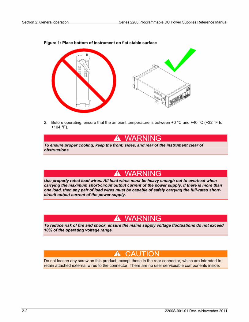
1. Place the bottom of the instrument on a bench or similar surface. Do not stand the instrument onit's rear panel. Refer to the following figure for an illustration of how to position the instrument.
Do not stand the instrument on its rear panel. This position is unstable and the instrument might tip over and be damaged or fall on someone and cause injury. To avoid damage or bodily injury, place the bottom of the instrument flat on a stable surface.
Section 2
General operation
Section 2: General operation Series 2200 Programmable DC Power Supplies Reference Manual
2-2 2200S-901-01 Rev. A/November 2011
Figure 1: Place bottom of instrument on flat stable surface
2. Before operating, ensure that the ambient temperature is between +0 °C and +40 °C (+32 °F to +104 °F).
To ensure proper cooling, keep the front, sides, and rear of the instrument clear of obstructions
Use properly rated load wires. All load wires must be heavy enough not to overheat when carrying the maximum short-circuit output current of the power supply. If there is more than one load, then any pair of load wires must be capable of safely carrying the full-rated short-circuit output current of the power supply.
To reduce risk of fire and shock, ensure the mains supply voltage fluctuations do not exceed 10% of the operating voltage range.
Do not loosen any screw on this product, except those in the rear connector, which are intended to retain attached external wires to the connector. There are no user serviceable components inside.
Series 2200 Programmable DC Power Supplies Reference Manual Section 2: General operation
2200S-901-01 Rev. A/November 2011 2-3
Installing the system This section contains information on how to install your Model 2200 power supply.
Unpack the instrument and check that you received all the items listed as standard accessories. Check that you also received any other accessories that you ordered with your instrument.
To verify that the power supply is ready to use, follow the procedures to:
Power the instrument on and off (on page 2-3) Check the output (on page 2-3)
Power the instrument on and off To power on the instrument follow these steps:
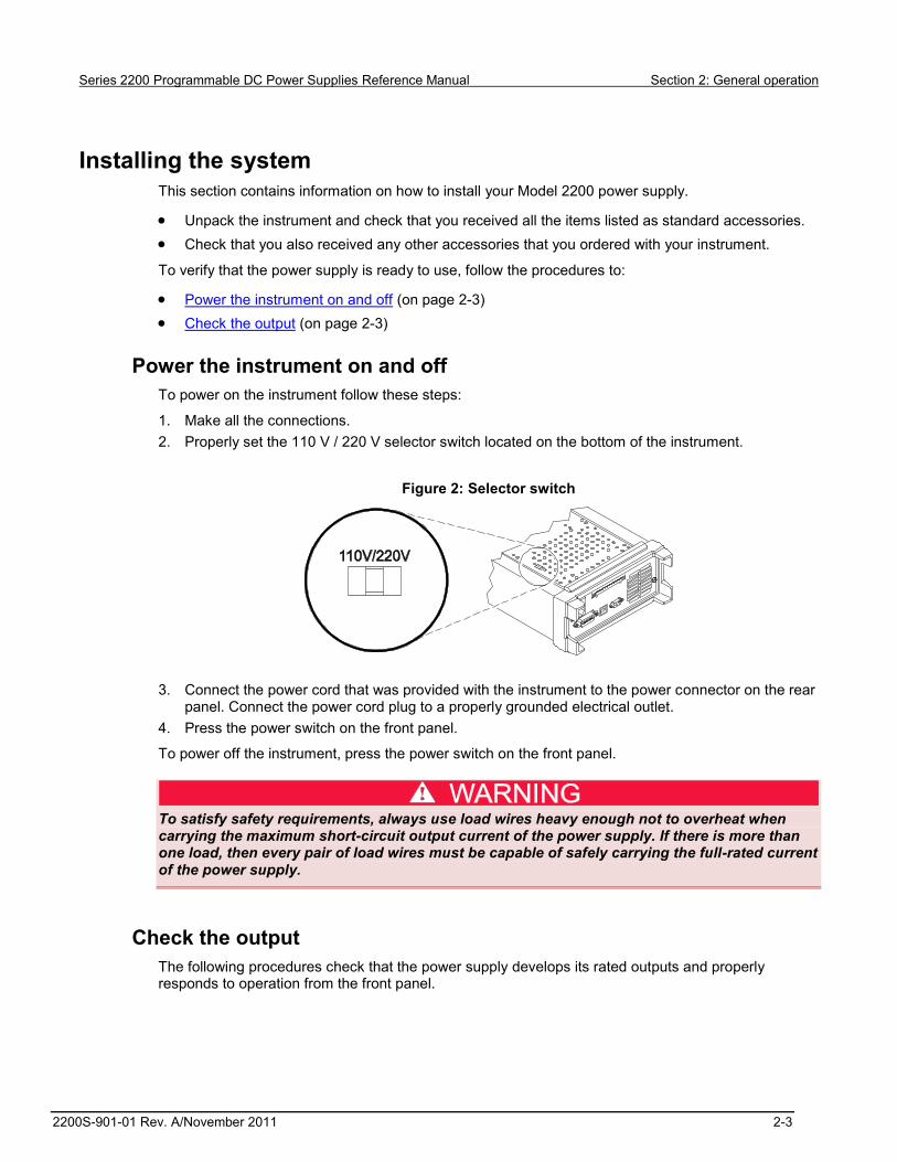
1. Make all the connections. 2. Properly set the 110 V / 220 V selector switch located on the bottom of the instrument.
Figure 2: Selector switch
3. Connect the power cord that was provided with the instrument to the power connector on the rear
panel. Connect the power cord plug to a properly grounded electrical outlet. 4. Press the power switch on the front panel.
To power off the instrument, press the power switch on the front panel.
To satisfy safety requirements, always use load wires heavy enough not to overheat when carrying the maximum short-circuit output current of the power supply. If there is more than one load, then every pair of load wires must be capable of safely carrying the full-rated current of the power supply.
Check the output The following procedures check that the power supply develops its rated outputs and properly responds to operation from the front panel.

Section 2: General operation Series 2200 Programmable DC Power Supplies Reference Manual
2-4 2200S-901-01 Rev. A/November 2011
Voltage output check To verify basic voltage functions without a load, follow these steps.
1. Remove all leads from the output connectors. 2. Turn on the power supply. 3. Press Shift and Menu (1). >Default Set shows on the display. 4. Press Enter to bring up the default settings options. No and Yes appear on the display. 5. Press the right arrow key to select Yes. Press Enter to enable the default settings. 6. Press the front-panel On/Off key to enable the output. The OFF message on the display turns off
and the CV message on the display turns on. The upper line of the display shows the actual output voltage and current. The lower line shows the settings.
7. Check that the front-panel voltmeter properly responds to pressing keys on the numeric keypad. Press V-set, use the numeric keypad to set the voltage value to 0 and press Enter. Check if the displayed voltage value is approximately 0 V and check if the displayed current value is approximately 0 A. You can confirm the 0 V setting with a voltmeter.
8. Press V-set and use the numeric keys and Enter to set the voltage value to the maximum allowable for your power supply, as indicated on the instrument’s front panel.
9. Check if the displayed voltage value is approximately the same value as the voltage setting.
Current output check To verify the basic current functions with a short across the power supply output, follow these steps:
1. Remove all leads from the output connectors. 2. Turn on the power supply. 3. Press Shift and Menu (1). >Default Set shows on the display. 4. Press Enter to bring up the default settings options. No and Yes appear on the display. 5. Press the right arrow key to select Yes. Press Enter to enable the default settings. 6. Ensure that the output is disabled and the display OFF message is turned on. If needed, press the
On/Off key to ensure that the output is disabled and the OFF message is turned on. 7. Use an insulated test lead to connect a short across the (+) and (-) output terminals.
Use a wire size sufficient to handle the maximum current. You should use at least a 22 gauge wire.
To satisfy safety requirements, always use load wires heavy enough not to overheat when carrying the maximum short-circuit output current of the power supply. If there is more than one load, then every pair of load wires must be capable of safely carrying the full-rated current of the power supply.
8. Press the On/Off key to enable the output. The CC message should be lit. 9. Press I-set and use the numeric keypad and Enter key to set the current value to 0 A. Check if
the displayed current value is approximately 0 A. 10. Press I-set and use the numeric keys and Enter to set the current value to the maximum
allowable for your current supply. Check if the displayed current value is approximately the same value as the maximum allowable.
11. Turn off the power supply and remove the short wire from the (+) and (-) output terminals.

Series 2200 Programmable DC Power Supplies Reference Manual Section 2: General operation
2200S-901-01 Rev. A/November 2011 2-5
Operating basics
Front panel at a glance The front panel of the Keithley Instruments Series 2200 contains the following items:
Power switch Display Arrow keys The navigation wheel Output connectors Keys Number keys
You can use the keys, display, and the navigation wheel to access, view, and edit the configuration menu items and set values.
For additional information about the front panel, see the Front panel operation (on page 2-15) section.
The front panel of the Series 2200 is shown in the following figure.
Figure 3: Front panel
(1) Display The display shows information.

Section 2: General operation Series 2200 Programmable DC Power Supplies Reference Manual
2-6 2200S-901-01 Rev. A/November 2011
(2) Information During operation, the display provides information about the output (top row) and settings (bottom row) for volts (left column) and current (right column). During configuration, the display shows the configuration menus (bottom row).
(3) Arrow keys Up, down, right, and left arrow keys (▲ and ▼) and Enter key.
(4) Navigation wheel Rotate the navigation wheel to increase or decrease digits or to select menu items.
(5) Output connectors Three banana jack output connectors provide high, low, and chassis ground connections.
(6) Save and recall keys See Key descriptions (on page 2-7) for descriptions of these keys.
(7) Numeric keypad The numeric keypad provides number keys (0 to 9 and Esc) for direct numeric entry.
(8) V-Set, I-Set, Shift, and Output On/Off keys See Key descriptions (on page 2-7) for descriptions of these keys.
(9) Power switch Press the power switch to turn the instrument on (|). Press it again to turn the instrument off (0).

Series 2200 Programmable DC Power Supplies Reference Manual Section 2: General operation
2200S-901-01 Rev. A/November 2011 2-7
Key descriptions The keys provide front panel control and configuration. See Front panel at a glance (on page 2-5) for an illustration of each key location. The following tables describe how to use each key.
Key descriptions
Keys Description
V-set Sets the voltage limit. See Setting the voltage limit (on page 2-17) for more information.
I-set Sets the current limit. See Setting the current limit (on page 2-17) for more information. Save Saves the present settings to a specified setup memory location (1 to 40). See Save
and recall setups (on page 2-18) for more information. Recall Recalls a saved setting from a specified setup memory location (1 to 40). See Save
and recall setups (on page 2-18) for more information. Shift Used to access secondary functions of the numeric keys. For example, when the Shift
key is used with the 1 key, the combination displays the configuration menu. See the following table for more information on Shift + numeric keypad descriptions.
Output On/Off
Turns on or off the output channel of the power supply. The regulation mode, constant voltage (CV) or constant current (CC), is shown on the display when the output is turned on.
Esc Backs out of the selected function. If the instrument’s focus is in a menu, pressing Esc will back up one menu level.
Shift + numeric keypad descriptions
Key Numeric keypad
Description
Shift 1 Brings up the configuration menus. Turn the navigation wheel or press the up or down keys to scroll through the list of menus. Press Enter to select which menu to use.
Shift 2 Brings up the list selection. Turn the navigation wheel or press the up or down arrow keys to scroll through the various lists you can run.
Shift 3 Generates a manual trigger event. Shift 7 Returns control from remote operation to local front panel control. This
operation generates a return to local message.

Section 2: General operation Series 2200 Programmable DC Power Supplies Reference Manual
2-8 2200S-901-01 Rev. A/November 2011
Keypad special operations See the following table for the Series 2200 keypad special operations.
Operation Key press Display the instrument firmware version. Shift + 8 Display the internal temperature of the instrument. Shift + . (decimal point) + 1
Perform a factory reset. All setups and lists are erased. Shift + . (decimal point) + 2 Unlock the keypad. If the instrument's keypad and front panel controls
are locked, you will need a password to unlock them. If you forget the password, enter the appropriate default code for the model instrument you are using: Model Default code 2200-20-5 4205 2200-30-5 4305 2200-32-3 4323 2200-60-2 4602 2200-70-1 4721
Cycling the instrument power also unlocks the keypad.

Series 2200 Programmable DC Power Supplies Reference Manual Section 2: General operation
2200S-901-01 Rev. A/November 2011 2-9
Configuration menus description Use the configuration menus to configure (setup) the instrument. Sometimes the configuration menus are called the settings menus. See the following table for information on the primary menu selections, secondary menu selections, options, and a brief description of each selection. The following table indicates default settings in bold.
Primary menu
Secondary menu First option Additional option(s)
Allows you to ...
>Default Set
No Yes Return the instrument to the factory default configuration. See Initializing to the default setup (on page 2-17) for more information.
>Protect >Reset Protect No Yes Reset Protect menu selections to the factory default configuration.
>Max Volt Set Off Turn maximum output voltage setting off.
On Max = Set or edit maximum output voltage for the instrument. See Setting the maximum voltage (on page 2-18) for more information.
>OVP Set Off Turn overvoltage protection (OVP) off.
On OVP = Turn overvoltage protection on and set or edit the voltage threshold. See Setting the overvoltage protection (on page 2-19) for more information.
>Out Time Set Off Turn out time mode off. On Time = Turn out time mode on and set or edit
the time period. See Timer example (on page 2-30) for an example of setting a timer with Out Time Set.
>Key Lock Password = unlock Indicates that no password is set to lock all front panel controls except power switch and output on/off key. Enter up to 4 digits to set a password.
Lck Indicates that a password has been set.
>Edit
List >Recall 1-7 Empty Recall or edit lists saved in up to 7
locations. Empty indicates no saved list. See Define a list of voltage and current steps (on page 2-24) for more information.
Continuous Repeat = Set instrument to continuous mode. If set, the instrument executes the entire sequence of steps as soon as it receives the next trigger signal. Repeat allows you to set or edit number of times to repeat the list. List Steps allows you to indicate the number of steps in the list. See List mode example (on page 2-31) for a list example.
Step Repeat = Set instrument to step mode. If set,

Section 2: General operation Series 2200 Programmable DC Power Supplies Reference Manual
2-10 2200S-901-01 Rev. A/November 2011
Primary menu
Secondary menu First option Additional option(s)
Allows you to ...
the instrument will advance to each step only after it receives a trigger signal. Repeat allows you to set or edit number of steps. List Steps allows you to indicate the number of steps in the list.
>User >Reset User No Yes Reset User menu selections to the factory default configuration.
>Output Recall Off Turn output recall mode off. On Set power output state to that which
was in use before power was last turned off. See Recall the power supply ON/OFF output state at power on (on page 2-20) for more information.
>Save Last On Save last operating parameters in use before turning instrument off. Restores saved parameters when instrument turned on. See Recall the power supply operating parameters at power on (on page 2-21) for more information.
Off Turns save last mode off. >Key Beep Off Turns off key press notification
sound. On Turns on key press notification
sound. See Setting the key sound (on page 2-21) for more information.
>Knob Lock Off Unlocks navigation wheel . On Locks navigation wheel . See Lock
the navigation wheel (on page 2-22) for more information.
>System >Reset System No Yes Reset System menu selections to the factory default configuration.
>Port Mode Trigger Set port mode input to trigger. You must also set the trigger source (Trig Source).
RI/Def Set port mode input and output to RI/Def. You must also set the remote inhibit mode (RI mode).
Digital Set port mode input and output to digital. This setting is for programmable interface commands described in Commands listed in alphabetical order (on page 4-2).
>Trig Source Manual Set rear panel port mode to manual trigger.
External Set rear panel port mode to external trigger.
Bus Set rear panel port mode to bus trigger.

Series 2200 Programmable DC Power Supplies Reference Manual Section 2: General operation
2200S-901-01 Rev. A/November 2011 2-11
Primary menu
Secondary menu First option Additional option(s)
Allows you to ...
Immediate Set rear panel port mode to immediate trigger.
>RI Mode Off Turn remote inhibit (RI) mode off. Latching Set remote inhibit mode to latching.
Latching mode turns the output channel off when the instrument detects a high-to-low transition (5 V to 0 V).
Live Set remote inhibit mode to live. Live mode the output channel off when the RI input is low (0 V) and on when the RI input is high (5 V)
>DFI Source Off Turn the discrete fault input (DFI) source mode off.
Ques Set the DFI source to question (Ques).
Oper Set the DFI source to operation (Oper).
ESB Set the DFI source to error status byte (ESB).
RQS Set the DFI source to request service (RQS.
>Communication USBTMC Set the communications mode to USBTMC.
GPIB Address=22 Set the communications mode to GPIB. Set or edit the GPIB primary address. See To change GPIB address settings (on page 3-2) for more information.
RS232 9600,8,N,1 Set the communication mode to RS232. Set or edit the RS232 address. USBTCM and GPIB are the recommended communication modes.

Section 2: General operation Series 2200 Programmable DC Power Supplies Reference Manual
2-12 2200S-901-01 Rev. A/November 2011
Upper display messages The instrument shows messages on the upper row of the display to indicate output operating and error conditions. See Configuring the instrument for your application (on page 2-16) for general information about these messages. See the following tables for the messages and a description of what the messages indicate.
Operating conditions
Messages Description
OFF Power supply output is off. CV Instrument is operating in constant voltage (CV) mode. CC Instrument is operation in constant current (CC) mode. RI Instrument output has been turned off by the remote inhibit (RI) input. See
[SOURce:]DIGital:FUNCtion (on page 4-12) for more information.
Error conditions
Messages Description
OVP Instrument has sensed a voltage level above the threshold set for overvoltage control and turned off the output. See Setting the overvoltage protection (on page 2-19) for more information.
RSV Instrument has sensed a reverse remote sense polarity condition and turned the output off. Polarities of source and sense connections must be the same. See Using remote sense (on page 2-23) for more information.
OTP Instrument has sensed an excessive internal temperature and turned off the output.
If the instrument displays the OTP message, the instrument should be shut down immediately .Do not operate the instrument when temperatures are above the internal temperature trip level to avoid damaging internal components.
Lower display messages The instrument shows the following messages on the lower row of the display.
Message Description
OVP If overvoltage protection (OVP) is set, the instrument displays the OVP message to Indicates that OVP is set. Flashes when OVP has tripped. See Setting the overvoltage protection (on page 2-19) for more information.
Lck If the front-panel controls are locked, the instrument displays the Lck message. See Configuration menus description (on page 2-9) for information on the >Protect >Key Lock configuration. See Keypad special operations (on page 2-8) for information on unlocking the front panel controls.
Series 2200 Programmable DC Power Supplies Reference Manual Section 2: General operation
2200S-901-01 Rev. A/November 2011 2-13
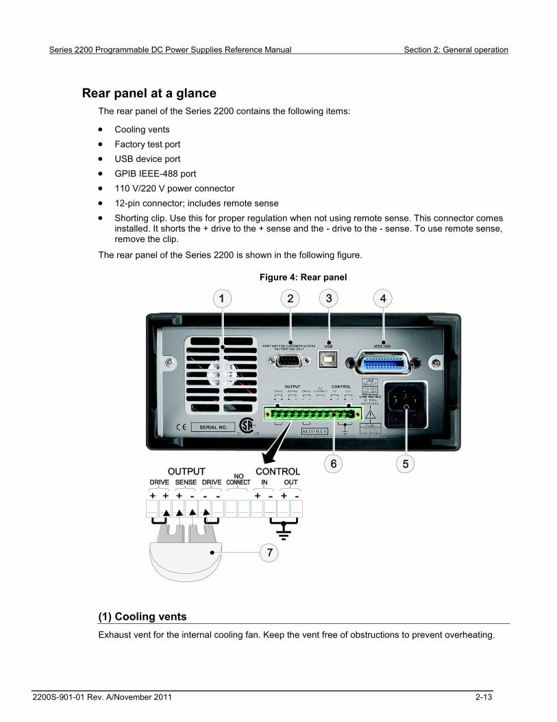
Rear panel at a glance The rear panel of the Series 2200 contains the following items:
Cooling vents Factory test port USB device port GPIB IEEE-488 port 110 V/220 V power connector 12-pin connector; includes remote sense Shorting clip. Use this for proper regulation when not using remote sense. This connector comes
installed. It shorts the + drive to the + sense and the - drive to the - sense. To use remote sense, remove the clip.
The rear panel of the Series 2200 is shown in the following figure.
Figure 4: Rear panel
(1) Cooling vents Exhaust vent for the internal cooling fan. Keep the vent free of obstructions to prevent overheating.

Section 2: General operation Series 2200 Programmable DC Power Supplies Reference Manual
2-14 2200S-901-01 Rev. A/November 2011
(2) Factory test port Do not use the factory test port.
Unauthorized use of the factory test port could damage this product.
(3) USB device port The USB 2.0 high-speed device port supports remote control and data transfer to a PC.
(4) General purpose interface bus (GPIB) connector The GPIB supports remote control and data transfer to a PC.
(5) 110 V/220 V power connector Using the supplied line cord, connect to a grounded AC power outlet.
(6) 12-pin connector The 12-pin connector includes remote sense. The illustration of the 12-pin connector (see Rear panel at a glance (on page 2-13).) shows the location of the following output and control connectors:
Two "Output Drive + " connectors are equivalent to the front-panel output + connector Two "Output Drive - " connectors are equivalent to the front-panel output - connector Two connectors: "Output Sense + " and "Output Sense - " are used for remote sensing Two No Connect connectors on the rear panel terminal strip are unused Four connectors "Control In + ", Control In - ", "Control Out + ", and Control In - " on the rear panel
terminal strip are configured by the port mode controls. They support the trigger, RI/DFI, and digital I/O functions. See >System in Configuration menus description (on page 2-9) for more information about the port mode controls.
(7) Shorting clip Use the shorting clip for proper regulation when not using remote sense. This connector comes installed. It shorts the + output drive to the + sense and the - output drive to the - sense for local sensing at the output terminals. To use remote sense, remove the clip.

Series 2200 Programmable DC Power Supplies Reference Manual Section 2: General operation
2200S-901-01 Rev. A/November 2011 2-15
110 V/220 V selector switch The 110 V/220 V selector switch is located on the bottom of the instrument as shown in the following figure.
Figure 5: Selector switch
Front panel operation Within a few seconds after turning on, the power supply displays the actual voltage and current output value on the display’s top line and the voltage and current settings on the bottom line.
You can enable or disable the output of the power supply from the front panel by pressing the Output On/Off key. When the output is off, the OFF message displays to the right of the current and voltage values.
The display shows the present operating status of the power supply with display messages. When the power supply operates in constant voltage mode, the CV message displays. When the power supply operates in the constant current mode, the CC message displays.
If the front panel was locked with a password, enter the correct password after you press a key (V-set, I-set, Save, Recall, or Shift), then you can change the settings.
To cancel a function operation (V-set, I-set, Save, Recall, or Shift), press Esc.

Section 2: General operation Series 2200 Programmable DC Power Supplies Reference Manual
2-16 2200S-901-01 Rev. A/November 2011
Configuring the instrument for your application The configuration menus (see Configuration menus description (on page 2-9)) includes settings, like OVP and Max Volt, that determine the maximum voltage output of the power supply. The menu system also includes settings, like Save Last and Output Recall, that determine how the instrument initializes itself when it is turned on.
This power supply features a constant voltage/constant current automatic crossover. This feature permits continuous operation in the transition from constant-voltage mode to constant-current mode as the load changes. The intersection of the constant-current and constant-voltage modes is called the crossover point.
For example, if the load is such that the power supply is operating in constant-voltage mode, the power supply provides a regulated output voltage. The output voltage remains constant as the load increases until the preset current limit is reached. Then the crossover occurs. At that point, the output current becomes constant and the output voltage drops in proportion to further load increases.
Crossover is indicated by the front panel CC and CV messages. If the CV message appears, the instrument is operating in constant-voltage mode. If the CC message appears, the instrument is operating in constant-current mode.
Crossover from the constant-current mode to the constant-voltage mode also occurs automatically in response to a decrease in load. For example, suppose you are charging a 12 V battery. Initially, the open circuit voltage of the power supply is preset for 13.8 V. A low-battery places a heavy load on the power supply, and it operates in constant-current mode. You adjust the instrument to charge the battery at the rate of 1 A. As the battery becomes charged and its voltage approaches 13.8 V, the load decreases to the point where the battery no longer demands the full 1 A charging rate. The power supply then crosses over to constant-voltage mode.

Series 2200 Programmable DC Power Supplies Reference Manual Section 2: General operation
2200S-901-01 Rev. A/November 2011 2-17
Initializing to the default setup Use the default setup to get the power supply into a default initial state:
1. Remove all leads from the output connectors. 2. Turn on the power supply. 3. Press Shift and Menu (1) to access the configuration menus. >Default Set shows on the
display. 4. Press Enter to bring up the default settings menu. No and Yes show on the display. 5. Press the right arrow key or navigation wheel to select Yes. 6. Press Enter to enable the default settings.
See the following table for the default settings.
Default setting Output On/Off OFF V-Set 1.000 V I-Set 0.1000 A Max Volt Set Off OVP Set Off Out Time Set Off Key Lock Off Output Recall Off Save Last On Key Beep Off Knob Lock Off Port Mode Trigger Trig Source Manual RI Mode Off DFI Source Off Communication RS232
Setting the current limit You may set the current limit from 0 A to the maximum current value of each model. The maximum current rating is shown on the instrument name plate.
1. Press I-set. 2. Use the arrow keys, numeric keypad, or the navigation wheel to enter the current limit. 3. Press Enter to set the current limit.
Setting the voltage limit You may set the voltage limit from 0 V to the maximum voltage rating shown on the instrument name plate.
1. Press V-set. 2. Use the arrow keys, numeric keypad, or the navigation wheel to enter the voltage limit. 3. Press Enter to set the voltage limit.
Section 2: General operation Series 2200 Programmable DC Power Supplies Reference Manual
2-18 2200S-901-01 Rev. A/November 2011
Save and recall setups You can store up to 40 different setups in setup memory locations (1 to 40). Each setup includes the set voltage limit, the set current limit, and the protection menu settings. When shipped from the factory, setup memories 1 through 40 are empty. Save and recall setups as follows:
To save a setup: 1. After you set up the power supply, (voltage and current limits and the protection menu settings),
push the Save key. 2. Use the arrow keys, numeric keypad, or the navigation wheel to select the setup memory (1 to
40) that you want to store the values in. 3. Press Enter to confirm the memory location.
To recall a setup: 1. Press Recall. 2. Use the arrow keys, numeric keypad, or the navigation wheel to select the setup memory that
you want to recall from. 3. Press Enter.
Setting the maximum voltage The Max Volt Set control determines the maximum voltage that you can set using the V-set control. This can help keep accidental over-voltage from being applied to sensitive loads. Set the maximum voltage as follows:
To set the maximum voltage: 1. Press Shift and Menu (1) to access the configuration menus. 2. Use the arrow keys, numeric keypad, or the navigation wheel to select >Protect. 3. Press Enter and turn the navigation wheel one click clockwise. >Max Volt Set shows on
the display. 4. Press Enter. Off (default) shows on the display. 5. Use the arrow keys, numeric keypad, or the navigation wheel to select On. 6. Press Enter to turn on the maximum voltage feature. 7. Use the numeric keys, arrow keys, or navigation wheel to change the voltage value. The value
must be less than the maximum voltage output noted on the nameplate of the power supply. 8. Press Enter. 9. Press Esc to exit the menu system.
When you adjust the voltage value to the maximum voltage limit, the voltage setting flashes back at you.
The default maximum voltage is the full voltage range of the particular power supply being used.

Series 2200 Programmable DC Power Supplies Reference Manual Section 2: General operation
2200S-901-01 Rev. A/November 2011 2-19
Setting the overvoltage protection The OVP Set control turns overvoltage protection (OVP) on or off. If overvoltage protection is turned on and the instrument senses a voltage level above the threshold set for over-voltage control, the instrument will turn off the output and clamp the voltage on the output to below one volt.
To set the overvoltage protection: 1. Press Shift and Menu (1) to access the configuration menus. 2. Use the arrow keys, numeric keypad, or navigation wheel to select >Protect. 3. Press Enter. 4. Use the up or down arrow keys to select >OVP Set. 5. Press Enter. 6. Select On. 7. Press Enter. 8. Enter the desired OVP value with the numeric keypad, arrow keys, or navigation wheel . 9. Press Enter
The lower display shows OVP when the overvoltage protection feature is activated. The OVP indicator will flash on and off when the overvoltage protection feature detects an overvoltage condition.
The default value for the Max Volt Set parameter is On.
Resetting the power supply after an overvoltage trip To reset the power supply after an overvoltage trip: 1. Determine and remove the source of the overvoltage. Overvoltage may be caused by setting the
voltage limit too high, external voltage sources, or equipment failure. 2. Press the Output On/Off key to clear the OVP status. This will put the power supply output in the
off state.
Section 2: General operation Series 2200 Programmable DC Power Supplies Reference Manual
2-20 2200S-901-01 Rev. A/November 2011
Recall the power supply ON/OFF output state at power on The Output Recall control determines the On or Off output state after the power supply is powered on. If you select On, the power supply will restore the state of the output to that which was in use before the power was last turned off. If the output was turned on when the power supply is turned off or loses power then the output will return to the On state when the power supply is turned back on or power is restored. Selecting Off will disable this function and the output channel will always be set to Off after the power supply is powered on.
To enable or disable this control: 1. Press the Shift and Menu (1) to access the configuration menus. 2. Use the up and down arrow keys to select >User. 3. Press Enter. 4. Use the up and down arrow keys to select >Output Recall. 5. Press Enter. 6. Use the up or down arrow keys to select >On or >Off. 7. Press Enter. 8. Press Esc to exit the menu system.
Wait 3 seconds after changing the settings to allow the settings to be completely stored before powering off the instrument.
The default value for the Output Recall control is Off.

Series 2200 Programmable DC Power Supplies Reference Manual Section 2: General operation
2200S-901-01 Rev. A/November 2011 2-21
Recall the power supply operating parameters at power on The Save Last control determines whether the power supply saves its most recent settings, such as voltage and current, and restores these settings at power on. If you set this control to Off then the power supply returns to the default settings at power on. If you select On, the power supply will restore the state to that which was in use before the power was last turned off.
To enable or disable this control: 1. Press Shift and then Menu (1) to access the configuration menus. 2. Use the arrow keys to select >User. 3. Press Enter. 4. Use the arrow keys to select >Save Last. 5. Press Enter. 6. Use the arrow keys to select >On or >Off. 7. Press Enter. 8. Press Esc to exit the menu system.
Wait 3 seconds after changing the settings to allow the settings to be completely stored before powering off the instrument
The default value for the Save Last control is On.
Setting the key sound The Key Beep control can switch on or off the beeper that sounds when you press any button or press any key.
To set the key sound: 1. Press Shift and Menu (1) to access the configuration menus. 2. Use the arrow keys, numeric keypad, or navigation wheel to select >User. 3. Press Enter. 4. Use the arrow keys to select >Key Beep. 5. Press Enter. 6. Use the arrow keys to select >On or >Off. 7. Press Enter. 8. Press Esc to exit the menu system.
The default value for the Key Beep control is Off.

Section 2: General operation Series 2200 Programmable DC Power Supplies Reference Manual
2-22 2200S-901-01 Rev. A/November 2011
Lock the navigation wheel The Knob Lock control can be used to lock the navigation wheel so it cannot be used to change settings or to select menu items.
To lock the navigation wheel : 1. Press Shift and Menu (1) to access the configuration menus. 2. Use the arrow keys, numeric keypad, or navigation wheel to select >User. 3. Press Enter. 4. Use the arrow keys, numeric keypad, or navigation wheel to select >Knob Lock. 5. Press Enter. 6. Use the arrow keys, numeric keypad, or navigation wheel to select >On or >Off. 7. Press Enter. 8. Press Esc to exit the menu system.
The default value for the Knob Lock control is Off.
Using local sense Configuring the power supply for local sense allows connection to the device under test with two lead wires, but does not compensate for voltage drop in the leads.
To configure for local sense: 1. On the rear panel terminal strip, install wires between DRIVE + and SENSE +, and between
DRIVE - and SENSE -. You may also use the included shorting clip described in Rear panel at a glance.
2. Connect to your device under test using two wires from either the front panel binding posts or the rear panel DRIVE + and DRIVE - terminals.

Series 2200 Programmable DC Power Supplies Reference Manual Section 2: General operation
2200S-901-01 Rev. A/November 2011 2-23
Using remote sense Use remote sensing to regulate the output voltage at the device under test. This feature lets you compensate for the voltage drop in the leads between the power supply front-end terminals and the device-under-test.
To set the remote sensing mode: 1. Remove any jumpers or shorting clip on the rear panel terminal strip connectors between DRIVE
+ and SENSE + and between DRIVE – and SENSE –. 2. See the following figure and connect a pair of sense leads from SENSE + and SENSE - to the
device under test.
To assure system stability, use a jacketed, twisted-pair cable between the remote sense terminals of the Series 2200 and the load.
3. Connect a pair of drive leads from the DRIVE + and DRIVE - to the device under test.
Figure 6: Load (device under test)
Section 2: General operation Series 2200 Programmable DC Power Supplies Reference Manual
2-24 2200S-901-01 Rev. A/November 2011
Define a list of voltage and current steps The Edit List feature lets you create up to seven sequences of steps, each with a voltage level, current level, and time duration.
To define and save a sequence, do the following: 1. Press Shift and Menu (1) to access the configuration menus. The instrument displays:
>Default Set 2. Use the arrow keys, numeric keypad, or navigation wheel to select >Edit List The instrument
displays: >Edit List
3. Press Enter. The instrument displays: Recall 1
4. Rotate the navigation wheel to select the number of the list to define or edit.You can choose from 1 to 7. The instrument displays: Recall 1
5. Press Enter. The instrument displays: Continuous
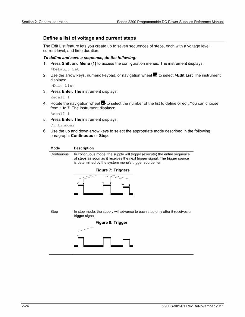
6. Use the up and down arrow keys to select the appropriate mode described in the following paragraph: Continuous or Step. Mode Description Continuous In continuous mode, the supply will trigger (execute) the entire sequence
of steps as soon as it receives the next trigger signal. The trigger source is determined by the system menu’s trigger source item.
Figure 7: Triggers
Step In step mode, the supply will advance to each step only after it receives a
trigger signal.
Figure 8: Trigger

Series 2200 Programmable DC Power Supplies Reference Manual Section 2: General operation
2200S-901-01 Rev. A/November 2011 2-25
7. Press Enter. The instrument displays:
Repeat 1 8. Use the keypad or navigation wheel to select the number of times to repeat the list. In this
example, 2 is used. This means that the instruction will run through the list of steps two times before stopping. The instrument displays: Repeat 2
9. Press Enter. The instrument displays: List Steps 4
10. Rotate the navigation wheel to select the number of steps in the list. In the example, 3 is used. The instrument displays: List Steps 3
11. Press Enter. The instrument displays: S 001 = 4.800 V
12. Use the keypad to set the voltage for this step. In the example, the voltage is set to 4.00 volts. The instrument displays: S 001 = 4.00 V.
13. Press Enter. The instrument displays: S 001 = 0.1000 A
14. Use the keypad to set the current for this step. In the example, the current is set to 1.500 amps. The instrument displays: S 001 = 1.500 A
15. Press Enter.The instrument displays: S 001 = 0.250 S
16. Use the keypad to set the time duration for this step. In the example, the duration is set to 0.100 seconds. The instrument displays: S 001 = 0. 100 S
17. Press Enter. The instrument displays: S 002 = 4.500 V
18. Repeat steps 11 through 17 for each of the number of steps selected in step 10 above. The instrument displays: Save List 1
19. Press the up or down arrow key to select the number of the list to save the current list to. In step 4 of this example, you started by selecting list 1. Now, you can save it in any of the 7 lists available to you. The instrument displays: >Edit List
20. Press Enter to save the list.
Running a list does not turn the output channel on. Before running a list, be sure to set the appropriate voltage and current and turn the output on.
21. Press Esc to exit the menu system.

Section 2: General operation Series 2200 Programmable DC Power Supplies Reference Manual
2-26 2200S-901-01 Rev. A/November 2011
Run a list of voltage and current steps To run a defined list of voltage and current steps, do the following: 1. Set the output voltage to what you want it to be set at before running the list and press the
Output On/Off key to turn the output on. 2. Press Shift and List (2). 3. Use the keypad or navigation wheel to select the list to run. 4. Press Enter. The power supply will wait for a trigger to start executing the list. The trigger source
depends on the setting of the Trigger Source control. See Configuration menus description (on page 2-9) for information on setting the >System >Trig Source control.
5. To run the selected list with a manual trigger, press Shift and Trigger (3). 6. To stop the list from running any more and to turn the output to off, press Esc.
See the Commands listed in alphabetical order (on page 4-2) section and Example 1 (on page 4-43) for information on programming the List Mode Function.
Rear panel operation The Series 2200 instrument supports two remote interfaces:
GPIB (general purpose interface bus) USB
The Series 2200 can only be controlled from one remote interface at a time. The unit will remote to the first interface on which it receives a message. It will ignore the other interface until the unit is taken back to local operation.
Connect to an external computer with IEEE-488 This topic contains information about GPIB standards, bus connections, and primary address selection.
GPIB standards
The GPIB is the IEEE-488 instrumentation data bus with hardware and programming standards originally adopted by the IEEE (Institute of Electrical and Electronic Engineers) in 1975. The instrument is IEEE Std 488.1 compliant and supports IEEE Std 488.2 common commands and status model topology.
Connect the GPIB cable
To connect a Series 2200 to the GPIB bus, use a cable equipped with standard IEEE-488 connectors, as shown below.

Series 2200 Programmable DC Power Supplies Reference Manual Section 2: General operation
2200S-901-01 Rev. A/November 2011 2-27
Figure 9: IEEE-488 connector
To allow many GPIB connections to other instruments, stack the cable connectors. Two screws are located on each connector to ensure that connections remain secure. The figure below shows a typical connection scheme for a multi-unit test system.
Figure 10: Series 2200 multiple parallel connections
To avoid possible mechanical damage, stack no more than three connectors on any one unit. To minimize interference caused by electromagnetic radiation, use only shielded IEEE-488 cables. Contact Keithley Instruments for shielded cables.

Section 2: General operation Series 2200 Programmable DC Power Supplies Reference Manual
2-28 2200S-901-01 Rev. A/November 2011
To connect the Series 2200 to the IEEE-488 bus, line up the cable connector with the connector located on the rear panel. Install and tighten the screws securely, making sure not to overtighten them (see Rear panel at a glance (on page 2-13) for the location of the connections).
Connect any additional connectors from other instruments as required for your application. Make sure the other end of the cable is properly connected to the controller. You can only have 15 devices connected to an IEEE-488 bus, including the controller. The maximum cable length is either 20 meters or two meters multiplied by the number of devices, whichever is less. Not observing these limits may cause erratic bus operation.
Primary address
The Series 2200 ships from the factory with a GPIB primary address of 22. You can set the address to a value from 0 to 30, but do not assign the same address to another device or to a controller that is on the same GPIB bus (controller addresses are usually 0 or 21).
Terminator
When receiving data over the GPIB, the instrument terminates messages on any line feed character or any data byte with EOI asserted (line feed with EOI asserted is also valid). When sending data, it appends a line feed character to all outgoing messages. The EOI line is asserted with the terminating line feed character.
Connect to an external computer with USB To connect to an external computer with USB: 1. Install a VISA driver on your computer. This driver is available on the Keithley Instruments
website. 2. Connect the instrument to the computer with a USB cable. The computer will then recognize the
power supply as a USB device.
Figure 11: Connect the instrument to the computer

Series 2200 Programmable DC Power Supplies Reference Manual Section 2: General operation
2200S-901-01 Rev. A/November 2011 2-29
Operation examples You can save tests in 40 memory locations to save up to 40 setups or use the Series 2200 List mode to define custom test sequences of up to 80 steps. This makes it easy to perform tests such as analyzing how your circuit or device under test performs at each voltage level within a range of voltages.
This topic provides examples of these operations. Each example describes how to complete the operation using both of the following methods:
Front-panel keystrokes Programming commands
Saving setups example This example describes how to set up the power supply to output 3.33 V, 1.6 A and save the setup in location 29 of the 40 setup memory locations available.
Keystrokes Perform the following steps using the keys on the instrument's front panel to save the test setup.
To configure the power supply: 1. Press V-Set. 2. Use the arrow keys, navigation wheel , or the keypad to input 3.33 V. Press Enter. 3. Press I-Set. 4. Use the arrow keys, navigation wheel , or the keypad to input 1.6 A. Press Enter.
To save the setup: 1. Press Save. 2. Use the arrow keys, navigation wheel , or the keypad to select memory location 29. Press
Enter.
To recall the setup:
Use the following keystrokes to recall the setup saved in memory location 29.
1. Press Recall. 2. Use the arrow keys, navigation wheel , or the keypad to select memory location 29. Press
Enter. The condition previously set displays.
Programming commands To configure and save the setup: *RST
SOURCE:FUNC:MODE FIX
SOURCE:VOLT 3.33V
SOURCE:CURR 1.6A
*SAV 29
To recall the setup:
Program the following command: *RCL 29

Section 2: General operation Series 2200 Programmable DC Power Supplies Reference Manual
2-30 2200S-901-01 Rev. A/November 2011
Timer example This example sets up the power supply to output 6 V, 1 A for 7 seconds before the output automatically turns off.
Keystrokes Perform the following procedure using the keys on the instrument's front panel to save the test setup.
To configure the duration of the timer and enable the timer feature: 1. Press Shift and Menu (1) to access the configuration menus. 2. Use the arrow keys, navigation wheel , or the keypad to select Protect. Press Enter. 3. Use the arrow keys, navigation wheel , or the keypad to select Out Time Set. Press Enter. 4. Use the arrow keys, navigation wheel , or the keypad to select On. Press Enter. 5. Use the arrow keys, navigation wheel , or the keypad to input Time = 7.00 S. Press
Enter. 6. Press Esc a few times to return to the initial screen. 7. Press V-Set. 8. Use the arrow keys, navigation wheel , or the keypad to input 6 V. Press Enter. 9. Press I-Set. 10. Use the arrow keys, navigation wheel , or the keypad to input 1 A. Press Enter. 11. Press Output On/Off to turn on the output.
Wait for 7 seconds. The output will turn off automatically
Programming commands *RST
SOURCE:FUNC:MODE FIX
SOURCE:VOLT 6V
SOURCE:CURR 1A
To configure the duration of the timer: OUTPUT:TIMER:DELAY 7S
To enable the timer feature: OUTPUT:TIMER:STATE ON
OUTPUT:STATE ON
To disable the timer feature: OUTPUT:TIMER:STATE OFF

Series 2200 Programmable DC Power Supplies Reference Manual Section 2: General operation
2200S-901-01 Rev. A/November 2011 2-31
List mode example This example configures a 5 step list to be executed 2 times in continuous mode. The list is saved in location 3. The instrument runs the list upon entering the list mode operation.
Step number Voltage level (V) Current level (A) Duration (sec) 1 2 5 0.001 2 5 5 0.001 3 1 1 1.000 4 7 3 0.001 5 3 1 0.001
Keystrokes
Use the following procedures to configure the list parameters,create the list steps, save the list, run, and stop running the list. In these procedures, you can use the arrow keys, numeric keypad, or the navigation wheel to select or enter numbers.
To configure the list parameters: 1. Press Shift and 1 to display the configuration menu. 2. Select Edit List. Press Enter. The display shows Recall 1. 3. Indicate that you want to save the list you are creating in location 3 by selecting 3 and pressing
Enter. The display shows Continuous. 4. Indicate that you want the continuous mode by selecting Continuous and pressing Enter. The
display shows Repeat 1. 5. Indicate that you want to repeat the sequence twice by selecting 2 and press Enter. The
display shows List Steps 1. 6. Indicate that there will be 5 steps in the list by selecting 5 and pressing Enter. The display shows
S 001= 0.000 V.
This completes entering the list parameters. You are ready to configure the first step.
To configure the first step in the list: 1. Input S 001= 2.000 V. Press Enter. The display shows S 001= 0.0000A. 2. Input S 001= 5.000 A as the current limit. Press Enter. The display shows S 001= 1.001S. 3. Input S 001= 0.001 S as the duration of the step. Press Enter. The display shows S 002=
0.000V.
This completes the configuration of the first step. You are ready to configure the second step.

Section 2: General operation Series 2200 Programmable DC Power Supplies Reference Manual
2-32 2200S-901-01 Rev. A/November 2011
To configure the second step in the list: 1. Input S 002= 5.000 V. Press Enter. The display shows S 002= 0.0000A. 2. Input S 002= 5.000 A as the current limit. Press Enter. The display shows
S 002= 1.0000A. 3. Input S 002= 0.001 S as the duration of the step. The display shows S 002= 0.001S. Press
Enter. The display shows S 003= 0.000V.
This completes the configuration of the second step. You are ready to configure the third step.
To configure the third step in the list: 1. Input S 003= 1.000 V. Press Enter. The display shows S 003= 0.0000A. 2. Input S 003= 1.000 A as the current limit. Press Enter. The display shows
S 003= 1.0000S. 3. Input S 003= 1.000 S as the duration of the step. The display shows S 003= 0.001S. Press
Enter. The display shows S 004= 0.000V.
This completes the configuration of the third step. You are ready to configure the fourth step.
To configure the fourth step in the list: 1. Input S 004= 7.000 V. Press Enter. The display shows S 004= 0.0000A 2. Input S 004= 3.000 A as the current limit. Press Enter. The display shows
S 004= 1.0000A. 3. Input S 004= 0.001 S as the duration of the step. The display shows S 004= 0.001S.
Press Enter.The display shows S 5= 0.000V.
This completes the configuration of the fourth step. You are ready to configure the fifth step.
To configure the fifth step in the list: 1. Input S 005= 3.000 V. Press Enter. The display shows S 005= 0.0000A. 2. Input S 005= 1.000 A as the current limit. Press Enter. S 003= 0.0001S. 3. Input S 005= 0.001 S as the duration of the step. Press Enter. The display shows
Save List 1.
This completes the configuration of the fifth step.
To save the list to location 3:
Input 3. Press Enter. This saves the list to location 3. The display shows >Edit List.
The list is now complete and saved. You are ready to run the list.
To run the list: 1. Press Output On/Off to turn on the output. 2. Press Shift and 2 to display the available list. 3. Use the arrow keys, the navigation wheel , or the keypad to select 3 as the location of the
saved list. 4. Press Enter. L3:EE is displayed while the power supply waits for a trigger. 5. Press Shift and 3 to to run the list.
You are ready to stop running the list.

Series 2200 Programmable DC Power Supplies Reference Manual Section 2: General operation
2200S-901-01 Rev. A/November 2011 2-33
To stop running the list: 1. Press Output On/Off to turn off the output 2. Press ESC to exit the list mode.
Programming commands To reset the power supply: *RST
To set the trigger source to be internal: TRIGGER:SOURCE:BUS
To configure the list: SOURCE:LIST:STEP 5
SOURCE:LIST:MODE CONT
SOURCE:LIST:COUT 2
SOURCE:LIST:VOLT 1, 2V
SOURCE:LIST:VOLT 2, 5V
SOURCE:LIST:VOLT 3, 1V
SOURCE:LIST:VOLT 4, 3V
SOURCE:LIST:VOLT 5, 7V
SOURCE:LIST:CURR 1, 5A
SOURCE:LIST:CURR 2, 5A
SOURCE:LIST:CURR 3, 1A
SOURCE:LIST:CURR 4, 3A
SOURCE:LIST:CURR 5, 1A
SOURCE:LIST:WIDTH 1, 0.001S
SOURCE:LIST:WIDTH 2, 0.001S
SOURCE:LIST:WIDTH 3, 1S
SOURCE:LIST:WIDTH 4, 0.001S
SOURCE:LIST:WIDTH 5, 0.001S
SOURCE:LIST:SAV 3
To run the list: OUTPUT ON
SOURCE:FUNC:MODE LIST
*TRG
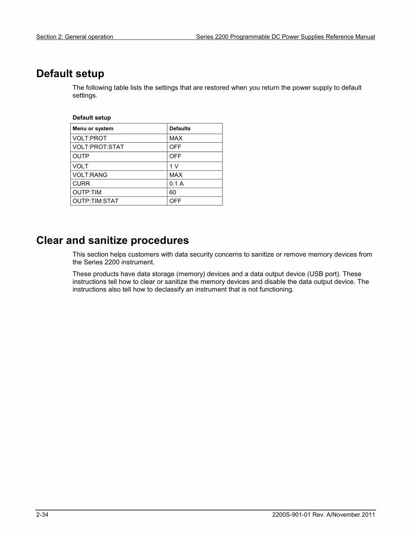
Section 2: General operation Series 2200 Programmable DC Power Supplies Reference Manual
2-34 2200S-901-01 Rev. A/November 2011
Default setup The following table lists the settings that are restored when you return the power supply to default settings.
Default setup
Menu or system Defaults
VOLT:PROT MAX VOLT:PROT:STAT OFF OUTP OFF
VOLT 1 V VOLT:RANG MAX CURR 0.1 A OUTP:TIM 60 OUTP:TIM:STAT OFF
Clear and sanitize procedures This section helps customers with data security concerns to sanitize or remove memory devices from the Series 2200 instrument.
These products have data storage (memory) devices and a data output device (USB port). These instructions tell how to clear or sanitize the memory devices and disable the data output device. The instructions also tell how to declassify an instrument that is not functioning.

Series 2200 Programmable DC Power Supplies Reference Manual Section 2: General operation
2200S-901-01 Rev. A/November 2011 2-35
Terms The following terms may be used in this topic.
Clear. This removes data on media/memory before reusing it in a secured area. All reusable memory is cleared to deny access to previously stored information by standard means of access.
Erase. This is equivalent to clear. Media storage/data export device. Any of several devices that can be used to store or export
data from the instrument, such as a USB port. Nonvolatile memory. Data is retained when the instrument is powered off. Power off. Some instruments have a “Standby” mode, in which power is still supplied to the
instrument. For the purpose of clearing data, putting the instrument in Standby mode does not qualify as powering off. For these products, you will need to either press a rear-panel OFF switch or remove the power source from the instrument.
Remove. This is a physical means to clear the data by removing the memory device from the instrument.
Sanitize. This eradicates the data from media/memory so that the data cannot be recovered by other means or technology. This is typically used when the device will be moved (temporarily or permanently) from a secured area to a non-secured area.
Scrub. This is equivalent to sanitize. User-modifiable. The user can write to the memory device during normal instrument operation,
using the instrument interface or remote control. Volatile memory. Data is lost when the instrument is powered off.

Section 2: General operation Series 2200 Programmable DC Power Supplies Reference Manual
2-36 2200S-901-01 Rev. A/November 2011
Memory devices The following tables list nonvolatile and volatile memory devices. Detailed procedures to sanitize or clear these devices are shown after the tables.
Nonvolatile memory devices
Type and minimum size
Function User modifiable
Data input method
Location To sanitize
EEPROM, 8k x 8 bit
Current setup, saved setups, and calibration constants
Yes Firmware operations and user input
Main board
See Clear nonvolatile memory devices procedure (on page 2-36).
Flash 8k x bit
List Data Yes Firmware operations and user input
Main board
See Clear nonvolatile memory devices procedure (on page 2-36).
AT91SAM7X256, 256k Flash
No Firmware update
CPU board See Clear volatile memory devices procedure (on page 2-36).
STM32F103C8, 64k – 128k Flash
No Firmware update
Main board See Clear volatile memory devices procedure (on page 2-36).
Volatile memory devices
Type and minimum size
Function User modifiable
Data input method
Location To clear
AT91SAM7X256, 64k SRAM
No Firmware operations
CPU board
Cycle power with minimum of 15 seconds off
STM32F103C8, 20k SRAM
No Firmware operations
Main board
Cycle power with minimum of 15 seconds off
Clear nonvolatile memory devices procedure This procedure clears the flash and EEPROM memory. After performing this procedure, the power supply will return to the factory default settings.
1. Press the front-panel Shift key. 2. Press the front-panel . (decimal point) key. 3. Press the front-panel 2 key.
Clear volatile memory devices procedure This procedure clears the STM32F103 and AT91SAM.
1. Press the front-panel power button to turn the instrument off. 2. Wait at least 15 seconds before turning the instrument back on.

Series 2200 Programmable DC Power Supplies Reference Manual Section 2: General operation
2200S-901-01 Rev. A/November 2011 2-37
Data export devices The following table lists the data export device. There are no procedures to disable these devices.
Data export device
Type and minimum size
Function User modifiable
Data input method Location To disable
USB dvice port Supports remote control and data transfer to a PC
Yes Remote control through USBTMC
Rear-panel of instrument
Cannot be disabled
GPIB port Supports remote control and data transfer to a PC
Yes Remote control through IEEE 488
Rear-panel of instrument
Cannot be disabled


In this section:
Section overview ...................................................................... 3-1 Communication interfaces ........................................................ 3-1 Command syntax ..................................................................... 3-3 Command groups ..................................................................... 3-9
Section overview This chapter explains how to use commands for remotely controlling the Series 2200 instruments. With this information, you can write computer programs to perform functions, such as setting the controls, taking measurements, performing statistical calculations, and exporting data for use in other programs.
The Commands listed in alphabetical order (on page 4-2) section provides detailed descriptions of each command.
Communication interfaces Your power supply has a USB 2.0 high-speed device port to control the power supply using the USBTMC protocol. The USBTMC protocol allows USB devices to communicate using IEEE-488.2 style messages.
You can also remotely communicate between your power supply and PC over General Purpose Interface Bus (GPIB).
Using the USB Start by connecting a USB cable (Keithley Instruments Model USB-B - 1) between the USB 2.0 high-speed device port on the rear panel of your power supply and a computer.
In order for the computer to recognize the power supply, a USBTMC driver must be installed on the computer.
Once the USBTMC driver is loaded, your computer will establish communication with the power supply upon USB cable connection.
Section 3
Remote operation

Section 3: Remote operation Series 2200 Programmable DC Power Supplies Reference Manual
3-2 2200S-901-01 Rev. A/November 2011
Using the GPIB Connector for IEEE-488 (GPIB) operation. Use a shielded cable, such as the Keithley Instruments Model 7007-1 or Model 7007-2.
Connect a GPIB cable from the Series 2200 instrument to your PC.
GPIB requirements Before setting up the power supply for remote communication using the electronic (physical) GPIB interface, you should familiarize yourself with the following recommendations:
A unique device address should be assigned to each device on the bus. No two devices should share the same device address.
No more than 15 devices can be connected to any one bus. Only one device should be connected for every 6 feet (2 meters) of cable used. No more than 65 feet (20 meters) of cable should be used to connect devices to a bus. At least two-thirds of the devices on the network should be on while using the network. Connect the devices on the network in a star or linear configuration. Do not use loop or parallel
configurations.
To change GPIB address settings Your power supply must have a unique device address to function properly. The default setting for the GPIB configuration is GPIB Address 22. If there is more than one GPIB instrument on the bus, you will need to change the default setting on the power supply.
To change the GPIB address settings, do the following: 1. On the instrument front-panel, press Shift and Menu (1). 2. Press the down arrow key or navigation wheel until you see System on the display, then press
Enter. 3. Press the down arrow key or navigation wheel until you see Communication on the display,
then press Enter. 4. Press the down arrow key or navigation wheel until you see GPIB on the display, then press
Enter. The display shows the GPIB address. For example, if the GPIB address is 22, the display will show Address=22.
5. Use the arrow keys, numeric keypad, or navigation wheel to change the GPIB address, then press Enter.
The power supply is now set up for bidirectional communication with your controller.
Command timing The average time it takes to both send and receive every command is approximately 20 ms. In the case of more complex commands, more time may be required to complete transmission.

Series 2200 Programmable DC Power Supplies Reference Manual Section 3: Remote operation
2200S-901-01 Rev. A/November 2011 3-3
Command syntax You can control the power supply through the GPIB or USB interface using commands and queries.
This section describes the syntax these commands and queries use and the conventions the power supply uses to process them. The commands and queries themselves are listed by group (see Command groups (on page 3-9)) and alphabetically (see Commands listed in alphabetical order (on page 4-2)).
You transmit commands to the power supply using the enhanced American Standard Code for Information Interchange (ASCII) character encoding. Appendix A contains a chart of the ASCII character set. The Backus Naur Form (BNF) notation listed in the following table is used in this manual to describe commands and queries.
BNF notation
Symbol Meaning
Defined element Is defined as Exclusive OR Group; one element is required Optional; can be omitted Previous element(s) may be repeated Comment

Section 3: Remote operation Series 2200 Programmable DC Power Supplies Reference Manual
3-4 2200S-901-01 Rev. A/November 2011
Command and query structure Commands consist of set commands and query commands (usually simply called commands and queries). Commands change power supply settings or perform a specific action. Queries cause the power supply to return data and information about its status.
Most commands have both a set form and a query form. The query form of the command is the same as the set form except that it ends with a question mark.
For example, the set command STATus:OPERation:ENAble has a query form STATus:OPERation:ENAble?. Not all commands have both a set and a query form; some commands are set only and some are query only.
A command message is a command or query name, followed by any information the power supply needs to execute the command or query. Command messages consist of five different element types described in the following table.
Command message elements
Symbol Meaning
<Header> The basic command name. If the header ends with a question mark, the command is a query. The header may begin with a colon (:) character; if the command is concatenated with other commands the beginning colon is required. The beginning colon can never be used with command headers beginning with a star (*).
<Mnemonic> A header subfunction. Some command headers have only one mnemonic. If a command header has multiple mnemonics, they are always separated from each other by a colon (:) character.
<Argument> A quantity, quality, restriction, or limit associated with the header. Not all commands have an argument, while other commands have multiple arguments. Arguments are separated from the header by a <Space>. Arguments are separated from each other by a <Comma>.
<Comma> A single comma between arguments of multiple-argument commands. It may optionally have white space characters before and after the comma.
<Space> A white space character between command header and argument. It may optionally consist of multiple white space characters.
The following figure shows the five command message elements.
Figure 12: Command message elements
Series 2200 Programmable DC Power Supplies Reference Manual Section 3: Remote operation
2200S-901-01 Rev. A/November 2011 3-5
Commands Commands cause the power supply to perform a specific function or change one of its settings. Commands have the structure: [:]<Header>[<Space><Argument>[<Comma><Argument>]...]
A command header is made up of one or more mnemonics arranged in a hierarchical or tree structure. The first mnemonic is the base or root of the tree and each subsequent mnemonic is a level or branch off of the previous one. Commands at a higher level in the tree may affect those at a lower level. The leading colon (:) always returns you to the base of the command tree.
Queries Queries cause the power supply to return information about its status or settings. Queries have the structure: [:]<Header>
[:]<Header>[<Space><Argument>[<Comma><Argument>]...]
You can specify a query command at any level within the command tree unless otherwise noted. These branch queries return information about all the mnemonics below the specified branch or level.
Query responses When a query is sent to the power supply, only the values are returned. When the returned value is a mnemonic, it is noted in abbreviated format, as shown in the following table.
Query response examples
Query Response
MEASure:VOLTage:DC? 5.0011 SOURce:FUNCtion:MODE? LIST
Command entry Follow these general rules when entering commands:
Enter commands in upper or lower case. You can precede any command with white space characters. White space characters include any
combination of the ASCII control characters 00 through 09 and 0B through 20 hexadecimal (0 through 9 and 11 through 32 decimal).
The power supply ignores commands that consists of just a combination of white space characters and line feeds.

Section 3: Remote operation Series 2200 Programmable DC Power Supplies Reference Manual
3-6 2200S-901-01 Rev. A/November 2011
SCPI commands and queries The power supply uses a command language based on the Standard Commands for Programmable Instruments (SCPI) standard. The SCPI standard was created by a consortium to provide guidelines for remote programming of instruments.
These guidelines provide a consistent programming environment for instrument control and data transfer. This environment uses defined programming messages, instrument responses and data formats that operate across all SCPI instruments, regardless of manufacturer.
The SCPI language is based on a hierarchical or tree structure that represents a subsystem. The top level of the tree is the root node; it is followed by one or more lower-level nodes as shown in the following figure.
Figure 13: Example of SCPI subsystem hierarchy tree
You can create commands and queries from these subsystem hierarchy trees. Commands specify actions for the instrument to perform. Queries return measurement data and information about parameter settings.
Message terminators This manual uses the term <EOM> (End of message) to represent a message terminator.
USB end of message (EOM) terminators.
See the USB Test and Measurement Class Specification (USBTMC) section 3.2.1 for details. The power supply terminates messages by setting the EOM bit in the USB header of the last transfer of a message to the host (USBTMC Specification section 3.3.1), and by terminating messages with a LF.
When receiving, the power supply expects a LF and an asserted EOM bit as a message terminator.

Series 2200 Programmable DC Power Supplies Reference Manual Section 3: Remote operation
2200S-901-01 Rev. A/November 2011 3-7
Parameter types Many power supply commands require parameters. Parameters are indicated by angle brackets, such as <file_name>. There are several different types of parameters, as listed in the following table. The parameter type is listed after the parameter. Some parameter types are defined specifically for the arbitrary/ function generator command set and some are defined by SCPI.
Types of parameters
Parameter type Description Example
boolean Boolean numbers or values ON or 0 OFF or 0
discrete A list of specific values MIN, MAX NR1 numeric Integers 0, 1, 15, -1 NR2 numeric Decimal numbers 1.2, 3.141516, -6.5 NR3 numeric Floating point numbers 3.1415E-9, -16.1E5 NRf numeric Flexible decimal number that may be type
NR1, NR2,or NR3 See NR1, NR2, NR3 examples in this table
string Alphanumeric characters (must be within quotation marks)
"Testing 1, 2, 3"
Abbreviating commands, queries, and parameters You can abbreviate most SCPI commands, queries, and parameters to an accepted short form. This manual shows these commands as a combination of upper and lower case letters. The upper case letters indicate the accepted short form of a command, as shown in the following figure. The accepted short form and the long form are equivalent and request the same action of the instrument.
Figure 14: Example of abbreviating a command

Section 3: Remote operation Series 2200 Programmable DC Power Supplies Reference Manual
3-8 2200S-901-01 Rev. A/November 2011
Chaining commands and queries You can chain several commands or queries together into a single message. To create a chained message, first create a command or query, then add a semicolon (;), and finally add more commands or queries and semicolons until you are done. If the command following a semicolon is a root node, precede it with a colon (:). The following figure illustrates a chained message consisting of several commands and queries. The chained message should end in a command or query, not a semicolon. Responses to any queries in your message are separated by semicolons.
Figure 15: Example of chaining commands and queries
If a command or query has the same root and lower-level nodes as the previous command or query, you can omit these nodes. In the following figure, the second command has the same root node (STAT:QUES) as the first command, so these nodes can be omitted.
Figure 16: Example of omitting root and lower level nodes
General rules for using SCPI commands The following are three general rules for using SCPI commands, queries, and parameters:
You can use single (‘ ’) or double (“ ”) quotation marks for quoted strings, but you cannot use both types of quotation marks for the same string.
correct “This string uses quotation marks correctly.” correct ‘This string also uses quotation marks correctly.’ incorrect “This string does not use quotation marks correctly.’

Series 2200 Programmable DC Power Supplies Reference Manual Section 3: Remote operation
2200S-901-01 Rev. A/November 2011 3-9
You can use upper case, lower case, or a mixture of both. No embedded spaces are allowed between or within nodes.
:SOURCE:FREQUENCY 10MHZ
is the same as :source:frequency 10mhz
and :SOURCE:frequency 10MHZ
No embedded spaces are allowed between or within nodes. correct :OUTPUT:FILTER:LPASS:FREQUENCY 200MHZ
incorrect :OUTPUT: FILTER: LPASS:FREQUENCY 200MHZ
Command groups This manual lists the power supply commands in two ways. First, it presents them by functional groups. Then, it lists them alphabetically. The functional group list starts below. The Commands listed in alphabetical order (on page 4-2) section provides details on each command.
The power supply interface conforms to Keithley standard codes and formats except where noted. The GPIB interface also conforms to IEEE Std 488.2–1987 except where noted. The USB interface also conforms to USB Test and Measurement Class, Subclass USB488 Specification, except where noted. Arguments are not mentioned in the group command descriptions, but are listed under the commands in the Commands listed in alphabetical order (on page 4-2) section of this manual.


In this section:
Commands listed in alphabetical order .................................... 4-2 *CLS (no query form) ............................................................... 4-2 CONFigure:SOUNd[:STATe] .................................................... 4-3 *ESE ........................................................................................ 4-3 *ESR? (query only) .................................................................. 4-4 FETCh:CURRent[:DC]? (query only) ....................................... 4-4 FETCh:VOLTage[:DC]? (query only) ....................................... 4-5 FETCh[:SCALar]:POWer? (query only) .................................... 4-5 *IDN? (query only) .................................................................... 4-6 MEASure:CURRent[:DC]? (query only) ................................... 4-6 MEASure:VOLTage[:DC]? (query only) ................................... 4-7 *OPC ........................................................................................ 4-7 *PSC ........................................................................................ 4-8 *RCL (no query form) ............................................................... 4-9 *RST (no query form) ............................................................... 4-9 *SAV (no query form) ............................................................. 4-10 [SOURce:]CURRent[:LEVel] .................................................. 4-10 [SOURce:]DIGital:DATA ........................................................ 4-11 [SOURce:]DIGital:FUNCtion .................................................. 4-12 [SOURce:]FUNCtion:MODE................................................... 4-13 [SOURce:]LIST:COUNt .......................................................... 4-13 [SOURce:]LIST:CURRent[:LEVel] .......................................... 4-14 [SOURce:]LIST:MODE ........................................................... 4-15 [SOURce:]LIST:RCL (no query form) ..................................... 4-15 [SOURce:]LIST:SAVe (no query form) ................................... 4-16 [SOURce:]LIST:STEP ............................................................ 4-16 [SOURce:]LIST:VOLTage[:LEVel] .......................................... 4-17 [SOURce:]LIST:WIDth ........................................................... 4-18 [SOURce:]OUTPut:DFI:SOURce ........................................... 4-19 [SOURce:]OUTPut:PON[:STATe] .......................................... 4-20 [SOURce:]OUTPut:PROTection:CLEar (no query form) ........ 4-20 [SOURce:]OUTPut:RI:MODE ................................................. 4-21 [SOURce:]OUTPut[:STATe] ................................................... 4-22 [SOURce:]OUTPut:TIMer:DELay ........................................... 4-23 [SOURce:]OUTPut:TIMer[:STATe] ......................................... 4-24 [SOURce:]VOLTage[:LEVel] .................................................. 4-25 [SOURce:]VOLTage:PROTection[:LEVel] .............................. 4-26 [SOURce:]VOLTage:PROTection:STATe .............................. 4-27 [SOURce:]VOLTage:RANGe ................................................. 4-28 *SRE ...................................................................................... 4-29 STATus:OPERation:CONDition? (query only) ....................... 4-29 STATus:OPERation:ENABle .................................................. 4-30 STATus:OPERation[:EVENt]? (query only) ............................ 4-31 STATus:QUEStionable:CONDition? (query only) ................... 4-31 STATus:QUEStionable:ENABle ............................................. 4-32 STATus:QUEStionable[:EVENt]? (query only) ....................... 4-33 STATus:QUEStionable:NTRansition ...................................... 4-34 STATus:QUEStionable:PTRansition ...................................... 4-35 *STB? (query only) ................................................................. 4-36 SYSTem:ERRor? (query only) ............................................... 4-36
Section 4
Command reference

Section 4: Command reference Series 2200 Programmable DC Power Supplies Reference Manual
4-2 2200S-901-01 Rev. A/November 2011
SYSTem:KEY ......................................................................... 4-37 SYSTem:LOCal (no query form) ............................................ 4-38 SYSTem:POSetup ................................................................. 4-38 SYSTem:REMote (no query form) ......................................... 4-39 SYSTem:RWLock (no query form) ......................................... 4-39 SYSTem:VERSion? (query only) ........................................... 4-39 *TRG (no query form) ............................................................. 4-40 TRIGger[:IMMediate] (no query form) .................................... 4-40 TRIGger:SOURce .................................................................. 4-41 *TST? (query only) ................................................................. 4-41 *WAI (no query form) ............................................................. 4-42 Programming examples ......................................................... 4-42
Commands listed in alphabetical order You can use commands to either set instrument features or query instrument values. You can use some commands to do both, some only to set and some only to query. This document marks set-only commands with the words “No Query Form” included with the command name. It marks query-only commands with a question mark appended to the header, and includes the words “Query Only” in the command name.
This document spells out headers, mnemonics, and arguments with the minimal spelling shown in uppercase. For example, to use the abbreviated form of the MEASure:SCALar:VOLTage:DC? command, type MEAS:SCAL:VOLT:DC?.
*CLS (no query form)
The *CLS command clears all event registers and queues.
Group Status
Syntax *CLS
Related Commands *ESR? (query only) (on page 4-4)
*STB? (query only) (on page 4-36)

Series 2200 Programmable DC Power Supplies Reference Manual Section 4: Command reference
2200S-901-01 Rev. A/November 2011 4-3
CONFigure:SOUNd[:STATe]
This command turns the key beep sound on or off.
Group System
Syntax CONFigure:SOUNd[:STATe] {0|1|ON|OFF} CONFigure:SOUNd[:STATe]?
Arguments 0 or OFF turns the key beep sound off. 1 or ON turns the key beep sound on.
Returns 0|1
Examples CONF:SOUN:OFF CONF:SOUN? might return 0, indicating the key beeper is turned off.
*ESE
Sets and queries the bits in the Event Status Enable Register (ESER). The ESER is an eight-bit mask register that determines which bits in the Standard Event Status Register(SESR) will set the ESB bit in the Status Byte Register (SBR) See Appendix C, Registers (on page C-3) for more information about registers.
Group Status
Syntax *ESE <mask> *ESE?
Related Commands *CLS (no query form) (on page 4-2)
*ESR? (query only) (on page 4-4)
Arguments <mask>::=<NR1>
where:
<NR1> is a value in the range from 0 through 255. The binary bits of the ESER are set according to this value.
The power-on default for ESER is 0 if *PSC is 1. If *PSC is 0, the ESER maintains its value through a power cycle.
Examples *ESE 145 sets the ESER to binary 10010001, which enables the PON, EXE, and OPC bits.
*ESE might return the string *ESE 186, showing that the ESER contains the binary value 10111010.

Section 4: Command reference Series 2200 Programmable DC Power Supplies Reference Manual
4-4 2200S-901-01 Rev. A/November 2011
*ESR? (query only)
Returns the contents of the Standard Event Status Register (SESR). *ESR? also clears the SESR (since reading the SESR clears it) See Appendix C, Registers (on page C-3) for more information about SESR.
Group Status
Syntax *ESR?
Related Commands *CLS (no query form) (on page 4-2)
*OPC (on page 4-7) *SRE (on page 4-29)
Returns <NR1>, which is a decimal representation of the contents of the Standard Event Status Register (SESR).
Examples *ESR? might return the value 149, showing that the SESR contains binary 10010101.
FETCh:CURRent[:DC]? (query only)
This command returns the last measured output current stored in the communications buffer of the power supply. A new measurement is not initiated by this command.
Group Measurement
Syntax FETCh:CURRent[:DC]?
Related Commands MEASure:CURRent[:DC]? (query only) (on page 4-6)
Returns <NR2>, which gives is the measured output current in amperes.
Examples FETC:VOLT? might return 5.0011, which would be the measured voltage across the power supply outputs in volts.

Series 2200 Programmable DC Power Supplies Reference Manual Section 4: Command reference
2200S-901-01 Rev. A/November 2011 4-5
FETCh:VOLTage[:DC]? (query only)
This command returns the last measured output voltage stored in the communications buffer of the power supply. A new measurement is not initiated by this command.
Group Measurement
Syntax FETCh:VOLTage[:DC]?
Related Commands MEASure:VOLTage[:DC]? (query only) (on page 4-7)
Returns <NR2> is the measured output voltage in volts.
Examples FETC:VOLT? might return 5.0011, which would be the measured voltage across the power supply outputs in volts.
FETCh[:SCALar]:POWer? (query only)
This command returns the last measured output current stored in the communications buffer of the power supply. A new measurement is not initiated by this command. The power calculation in the instrument is performed approximately every 100 ms. Insure that the voltage and current are stable longer than this for good results.
Group Measurement
Syntax FETCh[:SCALar]:POWer?
Returns <NR2> is the measured output power in watts.
Examples FETCh:POW? might return 6.01667, which would be the power measured at the output of t he power supply in watts.

Section 4: Command reference Series 2200 Programmable DC Power Supplies Reference Manual
4-6 2200S-901-01 Rev. A/November 2011
*IDN? (query only)
Returns the power supply identification code in IEEE 488.2 notation.
Group Status
Syntax *IDN?
Returns A string that includes <manufacturer>, <model>, <serial number>, and <firmware_version> as defined in the following table.
<manufacturer> <model> <serial number> <firmware_version>
Keithley Instruments 2200-XX-X XX-X.XX. X.XX-X.XX
Examples *IDN? might return the following response for a 2200-72-1 instrument:
Keithley Instruments, 2200-72-1, 081003126672201022, 1.25-1.23
MEASure:CURRent[:DC]? (query only)
This command initiates and executes a new current measurement, and returns the measured output current of the power supply.
Group Measurement
Syntax MEASure:CURRent[:DC]?
Related Commands FETCh:VOLTage[:DC]? (query only) (on page 4-5)
Returns <NR2> is the measured output current in amperes.
Examples MEAS:CURR? might return 0.09998, which would be the measured current on the output of the power supply in amperes.

Series 2200 Programmable DC Power Supplies Reference Manual Section 4: Command reference
2200S-901-01 Rev. A/November 2011 4-7
MEASure:VOLTage[:DC]? (query only)
This command initiates and executes a new voltage measurement, and returns the measured output voltage of the power supply.
Group Measurement
Syntax MEASure:VOLTage[:DC]?
Related Commands FETCh:VOLTage[:DC]? (query only) (on page 4-5)
Returns <NR2> is the measured output voltage in volts.
Examples MEAS:VOLT? might return 5.0011 which would be the voltage measured across the power supply output in volts.
*OPC
This command configures the instrument to generate an operation complete message by setting bit 0 of the Standard Event Status Register (SESR) when all pending commands that generate an OPC message are complete.
The query command places the ASCII character "1" into the output queue when all such OPC commands are complete.
Group Synchronization
Syntax *OPC *OPC?
Examples *OPC? might return 1 to indicate that all pending OPC operations are finished.

Section 4: Command reference Series 2200 Programmable DC Power Supplies Reference Manual
4-8 2200S-901-01 Rev. A/November 2011
*PSC
Sets and queries the power-on status flag that controls the automatic power-on execution of SRER and ESER. When *PSC is true, the SRER and ESER are set to 0 at power-on. When *PSC is false, the current values in the SRER and ESER are preserved in nonvolatile memory when power is shut off and are restored at power-on.
Group Source
Syntax *PSC <NR1> *PSC?
Related Commands *RST (no query form)
*OPC (on page 4-7)
Arguments <NR1> = 0 sets the power-on status clear flag to false, disables the power-on clear, and allows the power supply to possibly assert SRQ after power on.
<NR1> ≠ 0 sets the power-on status clear flag to true. Sending *PSC 1 therefore enables the power-on status clear and prevents any SRQ assertion after power-on.
Returns 0|1
Examples *PSC 0 sets the power-on status clear flag to false.
*PSC? might return 1, indicating that the power-on status clear flag is set to true.

Series 2200 Programmable DC Power Supplies Reference Manual Section 4: Command reference
2200S-901-01 Rev. A/November 2011 4-9
*RCL (no query form)
Restores the state of the power supply from a copy of its settings stored in the setup memory. The settings are stored using the *SAV command. If the specified setup memory is deleted, this command causes an error.
Group Save and Recall
Syntax *RCL <NR1>
Related Commands *SAV (no query form) (on page 4-10)
Arguments <NR1> is an integer value in the range from 0 to 40 and specifies the location of setup memory.
Examples *RCL 3 sets the power supply to settings stored in memory location 3.
*RST (no query form)
This command resets the power supply to default settings, but does not purge any stored settings.
Sending the *RST command does the following:
Returns the power supply settings to the defaults described in Default setup (on page 2-34).
Clears the pending operation flag and associated operations
The *RST command does not change the following items:
State of the USB or GPIB interface Calibration data that affects device specifications Current GPIB power supply address Stored settings Output queue Service Request Enable Register settings Standard Event Status Enable Register settings Power-On Status Clear flag setting front-panel LOCK state
Group Status
Syntax *RST
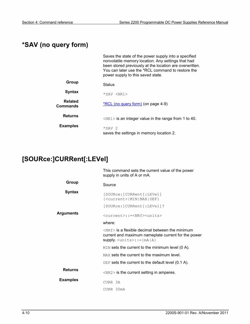
Section 4: Command reference Series 2200 Programmable DC Power Supplies Reference Manual
4-10 2200S-901-01 Rev. A/November 2011
*SAV (no query form)
Saves the state of the power supply into a specified nonvolatile memory location. Any settings that had been stored previously at the location are overwritten. You can later use the *RCL command to restore the power supply to this saved state.
Group Status
Syntax *SAV <NR1>
Related Commands *RCL (no query form) (on page 4-9)
Returns <NR1> is an integer value in the range from 1 to 40.
Examples *SAV 2 saves the settings in memory location 2.
[SOURce:]CURRent[:LEVel]
This command sets the current value of the power supply in units of A or mA.
Group Source
Syntax [SOURce:]CURRent[:LEVel]
{<current>|MIN|MAX|DEF}
[SOURce:]CURRent[:LEVel]?
Arguments <current>::=<NRf><units>
where:
<NRf> is a flexible decimal between the minimum current and maximum nameplate current for the power supply. <units>::={mA|A}
MIN sets the current to the minimum level (0 A).
MAX sets the current to the maximum level.
DEF sets the current to the default level (0.1 A).
Returns <NR2> is the current setting in amperes.
Examples CURR 3A
CURR 30mA

Series 2200 Programmable DC Power Supplies Reference Manual Section 4: Command reference
2200S-901-01 Rev. A/November 2011 4-11
CURR MIN
CURR? might return 2.0000, which would be the current setting in amperes.
[SOURce:]DIGital:DATA
This command sets the output state of the rear-panel TTL control output and queries the state of the rear-panel TTL control input. When the port mode is DIGITAL, this command is enabled.
Group Source
Syntax [SOURce:]DIGital:DATA <NR1>
[SOURce:]DIGital:DATA?
Arguments <NR1>::={0|1} sets the binary state of the rear-panel TTL control output to low or high state, respectively.
Returns <NR1>::={0|1|2|3} is a decimal representation of the state of the rear-panel TTL control output and input.
Value Input Pin 9 & 10
Output Pin 11 & 12
0 Low Low
1 Low High
2 High Low
3 High High
Examples DIGITAL:DATA ON
DIGITAL:DATA? might return 3, which would indicate that the TTL control input is high and the output is also high.

Section 4: Command reference Series 2200 Programmable DC Power Supplies Reference Manual
4-12 2200S-901-01 Rev. A/November 2011
[SOURce:]DIGital:FUNCtion
This command sets or queries the function of the TTL control lines on the rear panel of the power supply.
*RST value is TRIGger.
Group Source
Syntax [SOURce:]DIGital:FUNCtion {TRIGger|RIDFi|DIGital}
[SOURce:]DIGital:FUNCtion?
Related Commands TRIGger:SOURce (on page 4-41)
[SOURce:]OUTPut:DFI:SOURce (on page 4-19) [SOURce:]DIGital:DATA (on page 4-11)
Arguments Port Mode: TRIGger In: Trigger In Out: N/A Description: Configures the TTL control input as an external trigger source.
Port Mode: RIDFi In: RI Out: DFI Description: Configures the TTL control input as a remote inhibit (RI) input. The RI input can be used to turn the power supply output on or off from an external signal.
Configures the TTL control output as a Discrete Fault Input (DFI). The DFI output provides a signal indicating that an overvoltage, over-temperature, or improper remote sense connection fault has occurred.
Port Mode: DIGital In: DI Out: DO Description: It can read and control the output port state by command. It configures the TTL input and output for direct control using the [SOURce:]DIGital:DATA command.
Returns TRIG|RIDF|DIG
Examples DIGITAL:FUNCTION TRIGGER
DIG:FUNC? might return RIDF, which would indicate that the TTL input and output are configure to function as remote inhibit and discrete fault input respectively.

Series 2200 Programmable DC Power Supplies Reference Manual Section 4: Command reference
2200S-901-01 Rev. A/November 2011 4-13
[SOURce:]FUNCtion:MODE
This command configures the power supply to respond to discrete commands or to operate in list mode. Use this command with the FIXed parameter to exit list mode and prepare the instrument to respond to discrete settings changes.
Group Source
Syntax [SOURce:]FUNCtion:MODE {FIXed|LIST}
[SOURce:]FUNCtion:MODE?
Arguments FIXed configures the power supply to respond to discrete commands.
LIST configures the power supply to operate in list mode.
Returns FIX|LIST
Examples [SOURCE:]FUNCTION:MODE LIST
[SOURce:]LIST:COUNt
This command configures the number of times the active list will execute before stopping.
Group Source
Syntax [SOURce:]LIST:COUNt {<NR1>|ONCE|REPeat} [SOURce:]LIST:COUNt?
Related Commands [SOURce:]LIST:MODE (on page 4-15)
[SOURce:]LIST:COUNt (on page 4-13)
Arguments <NR1> is an integer between 2 and 65535. It determines the number of times the active list will execute. ONCe: configures the lists to execute once and stop. REPeat: configures the lists to loop continuously.
Returns <NR1> is the number of times the active list is set to execute.
Examples LIST:COUNT 6 would set the active list to execute 6 times before stopping.

Section 4: Command reference Series 2200 Programmable DC Power Supplies Reference Manual
4-14 2200S-901-01 Rev. A/November 2011
[SOURce:]LIST:CURRent[:LEVel]
This command sets the current for a list step in units of A or mA.
Group Source
Syntax [SOURce:]LIST:CURRent[:LEVel] <NR1>,<current> [SOURce:]LIST:CURRent[:LEVel]? <NR1>
Related Commands [SOURce:]LIST:VOLTage[:LEVel] (on page 4-17)
[SOURce:]LIST:WIDth (on page 4-18)
Arguments <NR1> is an integer in the range from 1 to 80, , which is a step number in the active list.
<current>::=<NRf>[<units] where <NRf> is a flexible decimal number used to specify a current setting in the range 0 amperes to the nameplate current rating of the power supply. <units>::={A|mA}
Returns <NR2> is a decimal representing the current setting in amperes for the step specified in the query.
Examples LIST:CURR 1, 3A
LIST:CURR? 1 might respond with 3.0000, which indicates the current level setting for step number 1.

Series 2200 Programmable DC Power Supplies Reference Manual Section 4: Command reference
2200S-901-01 Rev. A/November 2011 4-15
[SOURce:]LIST:MODE
This command determines the response of the power supply to a trigger in list mode.
Group Source
Syntax [SOURce:]LIST:MODE
{CONTinuous|STEP}[SOURce:]LIST:MODE?
Related Commands [SOURce:]LIST:COUNt (on page 4-13),
[SOURce:]LIST:STEP (on page 4-16)
Arguments CONTinuous: Sets the power supply to execute the entire list in response to a trigger.
STEP: Sets the power supply to execute one step per trigger.
Returns CONT|STEP
Examples LIST:MODE CONT
LIST:MODE? might respond with STEP to indicate that the active list is configured to wait for one trigger for each step.
[SOURce:]LIST:RCL (no query form)
This command recalls a previously saved list from the specified storage location and makes it the active list for editing or execution.
Group Source: List
Syntax [SOURce:]LIST:RCL <NR1>
Related Commands [SOURce:]LIST:SAVe (no query form) (on page 4-16)
Arguments <NR1> is an integer in the range from 1 to 8, representing a list storage location.
Examples LIST:RCL 5 would make the list stored in location 5 the active list for editing or execution.

Section 4: Command reference Series 2200 Programmable DC Power Supplies Reference Manual
4-16 2200S-901-01 Rev. A/November 2011
[SOURce:]LIST:SAVe (no query form)
This command saves the active list file to a storage location in non-volatile memory.
Group Source
Syntax [SOURce:]LIST:SAVe <NR1>
Related Commands [SOURce:]LIST:RCL (no query form) (on page 4-15)
Arguments <NR1> is an integer in the range from 1 to 8, representing a list storage location.
Examples LIST:SAV 4 saves the active list in list storage location 4.
[SOURce:]LIST:STEP
This command configures the number of steps in the active list. The number of steps must be configured before loading the voltage levels, current levels, and/or durations of the steps.
Group Source
Syntax [SOURce:]LIST:STEP {<NR1>|MIN|MAX} [SOURce:]LIST:STEP?
Related Commands [SOURce:]LIST:COUNt (on page 4-13),
[SOURce:]LIST:MODE (on page 4-15)
Arguments <NR1> is an integer in the range from 2 to 80, representing the number of steps to be configured in the list.
Returns <NR1> is the number of steps configured in the active list.
Examples Examples are provided in Programming examples (on page 4-42).

Series 2200 Programmable DC Power Supplies Reference Manual Section 4: Command reference
2200S-901-01 Rev. A/November 2011 4-17
[SOURce:]LIST:VOLTage[:LEVel]
This command sets the voltage level of a specified step in a list in units of V or mV.
Group Source: List
Syntax [SOURce:]LIST:VOLTage[:LEVel] <NR1>,<voltage>
Arguments <NR1> is an integer in the range from 1 to 80, which is a step number in the active list.
<voltage>::=<NRf><units>
where:
<NRf> is a flexible decimal that sets the voltage level fro the step. <units>::={V|mV}
Returns <NR2>
Examples LIST:VOLT 1, 3V
LIST:VOLT? 1 might return 3.0000, which would be the voltage level for step number 1.

Section 4: Command reference Series 2200 Programmable DC Power Supplies Reference Manual
4-18 2200S-901-01 Rev. A/November 2011
[SOURce:]LIST:WIDth
This command sets the duration of a specified step in a list.
Group Source
Syntax [SOURce:]LIST:WIDth <NR1>,{<duration>|MIN|MAX} [SOURce:]LIST:WIDth? <NR1>
Related Commands [SOURce:]LIST:VOLTage[:LEVel] (on page 4-17)
[SOURce:]LIST:CURRent[:LEVel] (on page 4-14)
Arguments <NR1> is an integer in the range from 1 to 80, which is a step number in the active list. <duration>::=<NRf><units>
where:
<NRf> is the time duration of the step <units>::={s|ms}
Returns <NR2>
Examples LIST:WIDTH 12, 100ms
LIST:WIDTH? 12 might return 0.1, which would be the duration of step 12.

Series 2200 Programmable DC Power Supplies Reference Manual Section 4: Command reference
2200S-901-01 Rev. A/November 2011 4-19
[SOURce:]OUTPut:DFI:SOURce
This command associates the DFI TTL output on the rear panel with a specified bit in the status byte register (SBR). Once the bit is associated with the DFI signal, the DFI signal will reflect the state of the specified bit. The port needs to be in the DFI or RI mode before using this command. Use the [SOURce:]DIGital:FUNCtion (on page 4-12) command to set the port mode.
*RST value is OFF.
Group Source: Digital I/O
Syntax [SOURce:]OUTPut:DFI:SOURce
{OFF|QUES|OPER|ESB|RQS}
[SOURce:]OUTPut:DFI:SOURce?
Related Commands [SOURce:]DIGital:FUNCtion (on page 4-12)
Arguments OFF: the output level of the DFI output pin remains high.
QUES: the output level of the DFI output pin reflects the complement of the state of the QUES bit. For example, when the QUES bit is 1, the DFI output pin is low.
OPER: the output level of the DFI output pin reflects the state of the OPER bit.
ESB: the output level of the DFI output pin reflects the state of the ESB bit.
RQS: the output level of the DFI output pin reflects the state of the RQS bit.
Returns OFF|QUES|OPER|ESB|RQS
Examples OUTput:DFI:SOURCE QUES sets the DFI signal to respond to the state of the QUES bit in the status byte register (SBR).

Section 4: Command reference Series 2200 Programmable DC Power Supplies Reference Manual
4-20 2200S-901-01 Rev. A/November 2011
[SOURce:]OUTPut:PON[:STATe]
This command configures the power supply to power up with its output turned off, or to return the output to the state it was in when it powered down.
Group Source
Syntax [SOURce:]OUTPut:PON[:STATe] {RST|RCL0}
[SOURce:]OUTPut:PON[:STATe]?
Arguments RST sets the power supply to power-up with output off.
RCL0 sets the power supply to power-up with the output in the last state before power was removed.
Returns RST|RCL0
Examples OUTPUT:PON RST
OUTPUT:PON? might return RCL0, which would indicate that the instrument will return to the present output state if the power is cycled.
[SOURce:]OUTPut:PROTection:CLEar (no query form)
This command clears a trip condition caused by over voltage (OV), over temperature (OT), or remote inhibit (RI).
Group Source
Syntax [SOURce:]OUTPut:PROTection:CLEar
Related Commands [SOURce:]VOLTage:PROTection[:LEVel] (on page 4-26)
Examples OUTP:PROT:CLE

Series 2200 Programmable DC Power Supplies Reference Manual Section 4: Command reference
2200S-901-01 Rev. A/November 2011 4-21
[SOURce:]OUTPut:RI:MODE
This command sets the input mode of the RI (remote inhibit) input pin. In order for this command to be effective, the rear panel TTL input and output must be configured in RI/DFI mode using the [SOURce:]DIGital:FUNCtion (on page 4-12) command.
Group Source
Syntax [SOURce:]OUTPut:RI:MODE {OFF|LATChing|LIVE} [SOURce:]OUTPut:RI:MODE?
Related Commands [SOURce:]DIGital:FUNCtion (on page 4-12)
Arguments OFF: The level of the RI input pin does not affect the output state of the power supply.
LATChing: When the level of the RI input pin changes from high to low, the output of power supply turns off.
LIVE: The output state of power supply changes according to the level of the RI input pin. While the level is TTL high, the output will be on. While the level is TTL low, the output of the power supply will be off.
Returns OFF|LATC|LIVE
Examples OUTP:RI:MODE LATC
OUTP:RI:MODE? might return OFF, which would indicate that remote inhibit is not controlling the output of the instrument.

Section 4: Command reference Series 2200 Programmable DC Power Supplies Reference Manual
4-22 2200S-901-01 Rev. A/November 2011
[SOURce:]OUTPut[:STATe]
This command turns the power supply output channel on or off.
Group Source
Syntax [SOURce:]OUTPut[:STATe] {0|1|ON|OFF} [SOURce:]OUTPut[:STATe]?
Related Commands [SOURce:]VOLTage:PROTection[:LEVel] (on page 4-26)
[SOURce:]VOLTage:RANGe (on page 4-28)
Arguments 0 or OFF turns the power supply output off.
1 or ON turns the power supply output on.
Returns 1|0
Examples OUTPUT ON
OUTPUT? might return 0, which would indicate that the output is off.

Series 2200 Programmable DC Power Supplies Reference Manual Section 4: Command reference
2200S-901-01 Rev. A/November 2011 4-23
[SOURce:]OUTPut:TIMer:DELay
This command sets the time duration of the output timer. When the timer is activated and a duration is set, the output of the power supply will turn off automatically if left on longer than the specified duration. In order to ensure proper operation of the output timer, the timer must be activated using the [SOURce:]OUTPut:TIMer[:STATe] (on page 4-24) command before turning the output on.
Group Source
Syntax [SOURce:]OUTPut:TIMer:DELay
{<duration>|MIN|MAX|DEF}
[SOURce:]OUTPut:TIMer:DELay?
Related Commands [SOURce:]OUTPut:TIMer[:STATe] (on page 4-24)
[SOURce:]OUTPut[:STATe] (on page 4-22)
Arguments <duration> ::= <NRf><units>
where:
<NRf> is a flexible decimal specifying time in the range 0.01s (or 10ms) to 60000s.
<units>::={S|ms}
MIN: The minimum time of the output timer (0.01 s).
MAX: The maximum time of the output timer (60,000 s).
DEF: The default time of the output timer (60 s).
Returns <NR2> is the timer duration in seconds.
Examples OUTP:TIM:DEL MIN
OUTP:TIM:DEL? might return 60.2, which would represent the maximum time, in seconds, that the output of the instrument could be turned on if the timer is active.
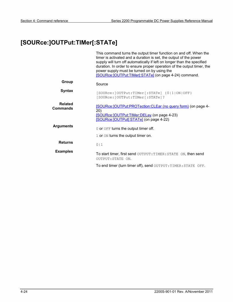
Section 4: Command reference Series 2200 Programmable DC Power Supplies Reference Manual
4-24 2200S-901-01 Rev. A/November 2011
[SOURce:]OUTPut:TIMer[:STATe]
This command turns the output timer function on and off. When the timer is activated and a duration is set, the output of the power supply will turn off automatically if left on longer than the specified duration. In order to ensure proper operation of the output timer, the power supply must be turned on by using the [SOURce:]OUTPut:TIMer[:STATe] (on page 4-24) command.
Group Source
Syntax [SOURce:]OUTPut:TIMer[:STATe] {0|1|ON|OFF} [SOURce:]OUTPut:TIMer[:STATe]?
Related Commands [SOURce:]OUTPut:PROTection:CLEar (no query form) (on page 4-
20) [SOURce:]OUTPut:TIMer:DELay (on page 4-23) [SOURce:]OUTPut[:STATe] (on page 4-22)
Arguments 0 or OFF turns the output timer off.
1 or ON turns the output timer on.
Returns 0|1
Examples To start timer, first send OUTPUT:TIMER:STATE ON, then send OUTPUT:STATE ON.
To end timer (turn timer off), send OUTPUT:TIMER:STATE OFF.

Series 2200 Programmable DC Power Supplies Reference Manual Section 4: Command reference
2200S-901-01 Rev. A/November 2011 4-25
[SOURce:]VOLTage[:LEVel]
This command sets the voltage value of the power supply.
Group Source
Syntax [SOURce:]VOLTage[:LEVel] {<NRf>|MIN|MAX|DEF}
[SOURce:]VOLTage[:LEVel]?
Related Commands [SOURce:]CURRent[:LEVel] (on page 4-10)
Arguments <voltage>
where:
<voltage>::=<NRf><units>
<NRf> is a flexible decimal specifying the voltage setting, ranging from 0 to the maximum nameplate voltage of the power supply.
<units>::={V|mV|kV}
MIN sets the voltage to the minimum level (0 V).
MAX sets the voltage to the maximum level (note that the maximum level may be somewhat higher than the nameplate).
DEF is the default level (1 V).
Returns NR2 is the voltage setting in volts.
Examples VOLTAGE:MIN
VOLTAGE? might return 1.05, which would be the voltage setting in volts.

Section 4: Command reference Series 2200 Programmable DC Power Supplies Reference Manual
4-26 2200S-901-01 Rev. A/November 2011
[SOURce:]VOLTage:PROTection[:LEVel]
This command sets the over voltage protection (OVP) threshold level.
Group Source
Syntax [SOURce:]VOLTage:PROTection[:LEVel]
{<voltage>|MIN|MAX|DEF}
[SOURce:]VOLTage:PROTection[:LEVel]?
Related Commands [SOURce:]VOLTage:PROTection[:LEVel] (on page 4-26)
[SOURce:]VOLTage:RANGe (on page 4-28)
Arguments <voltage>::=<NRf><units>
where:
<NRf> is a flexible decimal that specifies the OVP threshold, ranging from 0 to the maximum OVP level <units> ::={V|mV}
MIN: sets the minimum OVP level (1 V).
MAX: sets the maximum OVP level, which is approximately 10% higher than the maximum output voltage rating of the power supply.
DEF: sets the OVP level to the default level, which is equal to MAX.
Returns <NR2> is the OVP threshold in volts.
MIN: set to minimum OVP level.
MAX: set to maximum OVP level.
Examples VOLT:PROT 30V
VOLT:PROT? might return 30, which would be the OVP threshold in volts.

Series 2200 Programmable DC Power Supplies Reference Manual Section 4: Command reference
2200S-901-01 Rev. A/November 2011 4-27
[SOURce:]VOLTage:PROTection:STATe
This command activates, deactivates, or checks the status of overvoltage protection (OVP).
Group Source
Syntax [SOURce:]VOLTage:PROTection:STATe {0|1|OFF|ON}
[SOURce:]VOLTage:PROTection:STATe?
Related Commands [SOURce:]VOLTage:PROTection[:LEVel] (on page 4-26)
[SOURce:]VOLTage:RANGe (on page 4-28)
Arguments 0 or OFF sets the over voltage protection to off.
1 or ON sets the over voltage protection to on.
Returns 0|1 means the over voltage protection is off.
Examples VOLT:PROT:STAT 1
VOLT:PROT:STAT? might return 1, which would indicate that overvoltage protection is active.

Section 4: Command reference Series 2200 Programmable DC Power Supplies Reference Manual
4-28 2200S-901-01 Rev. A/November 2011
[SOURce:]VOLTage:RANGe
This command limits the maximum voltage that can be programmed on the power supply. This command corresponds to the front-panel Max Voltage setting that can be found under the Protection submenu. This function is different from OVP, since it cannot turn the output off.
Group Source
Syntax [SOURce:]VOLTage:RANGe {<voltage>|MIN|MAX|DEF}
[SOURce:]VOLTage:RANGe?
Related Commands [SOURce:]VOLTage:PROTection[:LEVel] (on page 4-26)
[SOURce:]VOLTage:PROTection:STATe (on page 4-27)
Arguments <voltage>::=<NRf><units>
where:
<NRf> is a flexible decimal that sets the maximum output voltage, ranging from 0 to the maximum nameplate voltage
<units>::={V|mV|kV}
MIN: sets the voltage limit to the minimum value (0 V).
MAX: sets the voltage limit to the maximum value which is slightly higher than the maximum nameplate voltage.
DEF: sets the voltage limit to the default value, which equals MAX.
Returns <NR2> is the voltage limit in volts.
Examples VOLT:RANG 3.2V
VOLT:RANG? might return 3.2, which would be the maximum programmable voltage in volts.

Series 2200 Programmable DC Power Supplies Reference Manual Section 4: Command reference
2200S-901-01 Rev. A/November 2011 4-29
*SRE
Service request enable (SRE) sets and queries the bits in the service request enable register (SRER). See Appendix C, Registers (on page C-3) for more information about SRER.
Group Status
Syntax *SRE <NR1> *SRE?
Related Commands *CLS (no query form) (on page 4-2)
*ESR? (query only) (on page 4-4) *PSC (on page 4-8)
Arguments <NR1> is an integer value in the range from 0 to 255. The binary bits of the SRER are set according to this value. Using an out-of-range value causes an execution error. The power-on default for SRER is 0 if *PSC is 1. If *PSC is 0, the SRER maintains its value through a power cycle.
Examples *SRE 48 sets the bits in the SRER to 00110000 binary.
*SRE? might return a value of 32, showing that the bits in the SRER have the binary value 00100000.
STATus:OPERation:CONDition? (query only)
This command returns the contents of the operation condition register (OCR). Details on the OCR are available in Appendix C, Registers (on page C-3).
Group Status
Syntax *SRE <NR1>
*SRE?
Related Commands *CLS (no query form) (on page 4-2)
*ESR? (query only) (on page 4-4) *PSC (on page 4-8)
Arguments <NR1> is an integer value in the range from 0 to 255. The binary bits of the service request enable register (SRER) are set according to this value. Using an out-of-range value causes an execution error. The power-on default for SRER is 0 if *PSC is 1. If *PSC is 0, the SRER maintains its value through a power cycle.
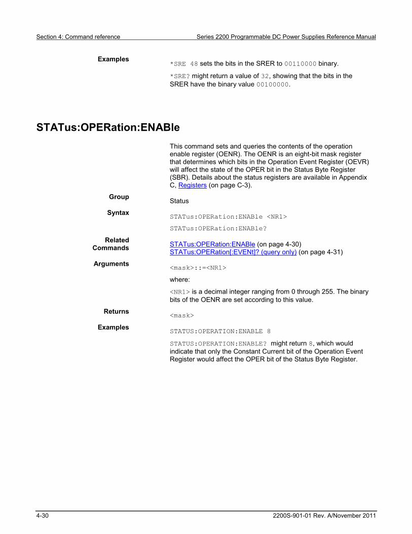
Section 4: Command reference Series 2200 Programmable DC Power Supplies Reference Manual
4-30 2200S-901-01 Rev. A/November 2011
Examples *SRE 48 sets the bits in the SRER to 00110000 binary.
*SRE? might return a value of 32, showing that the bits in the SRER have the binary value 00100000.
STATus:OPERation:ENABle
This command sets and queries the contents of the operation enable register (OENR). The OENR is an eight-bit mask register that determines which bits in the Operation Event Register (OEVR) will affect the state of the OPER bit in the Status Byte Register (SBR). Details about the status registers are available in Appendix C, Registers (on page C-3).
Group Status
Syntax STATus:OPERation:ENABle <NR1>
STATus:OPERation:ENABle?
Related Commands STATus:OPERation:ENABle (on page 4-30)
STATus:OPERation[:EVENt]? (query only) (on page 4-31)
Arguments <mask>::=<NR1>
where:
<NR1> is a decimal integer ranging from 0 through 255. The binary bits of the OENR are set according to this value.
Returns <mask>
Examples STATUS:OPERATION:ENABLE 8
STATUS:OPERATION:ENABLE? might return 8, which would indicate that only the Constant Current bit of the Operation Event Register would affect the OPER bit of the Status Byte Register.

Series 2200 Programmable DC Power Supplies Reference Manual Section 4: Command reference
2200S-901-01 Rev. A/November 2011 4-31
STATus:OPERation[:EVENt]? (query only)
This command returns the contents of the operation event register (OEVR). After executing this command the operation event register is reset. Details about the status registers are available in Appendix C, Registers (on page C-3).
Group Status
Syntax STATus:OPERation[:EVENt]?
Related Commands STATus:OPERation:CONDition? (query only) (on page 4-29)
STATus:OPERation[:EVENt]? (query only) (on page 4-31)
Arguments <NR1> is a decimal integer representation of the contents of the Operation Event Register (OEVR), ranging from 0 to 255.
Examples STATUS:OPERATION:EVENT? might return 10, which indicates that the power supply is waiting for trigger and is in a constant current mode.
STATus:QUEStionable:CONDition? (query only)
This command returns the contents of the questionable condition register (QCR).Details about the status registers are available in Appendix C, Registers (on page C-3).
Group Status
Syntax STATus:QUEStionable:CONDition?
Related Commands STATus:QUEStionable:ENABle (on page 4-32)
STATus:QUEStionable[:EVENt]? (query only) (on page 4-33)
Returns <NR1> is a decimal integer representation of the contents of the Questionable Condition Register (OCR), ranging from 0 to 255.
Examples STATUS:QUESTIONABLE:CONDITION? might return 1, which would indicate an over voltage condition.

Section 4: Command reference Series 2200 Programmable DC Power Supplies Reference Manual
4-32 2200S-901-01 Rev. A/November 2011
STATus:QUEStionable:ENABle
This command sets and queries the contents of the questionable enable register (QENR). The QENR is an eight-bit mask register that determines which bits in the Questionable Event Register (QEVR) will affect the state of the QUES bit in the Status Byte Register (SBR).
Group Status
Syntax STATus:QUEStionable:ENABle <mask>
STATus:QUEStionable:ENABle?
Related Commands STATus:QUEStionable[:EVENt]? (query only) (on page 4-33)
STATus:QUEStionable:CONDition? (query only) (on page 4-31)
STATus:QUEStionable:PTRansition (on page 4-35)
STATus:QUEStionable:NTRansition (on page 4-34)
*PSC (on page 4-8)
Arguments <mask>::=<NR1>
where:
<NR1> is a decimal integer ranging from 0 through 255. The binary bits of the QENR are set according to this value.
Returns <mask>
Examples STATUS:QUESTIONABLE:ENABLE 8
STATUS:QUESTIONABLE:ENABLE? might return 8, which would indicate that only a transition of the Remote Inhibit bit of the QCR would affect the QUES bit of the Status Byte Register.

Series 2200 Programmable DC Power Supplies Reference Manual Section 4: Command reference
2200S-901-01 Rev. A/November 2011 4-33
STATus:QUEStionable[:EVENt]? (query only)
This command returns the contents of the questionable event register (QEVR). After executing this command, the quest event register is reset. Details about the QEVR are available in Appendix C, Registers (on page C-3).
Group Status
Syntax STATus:QUEStionable[:EVENt]?
Related Commands STATus:QUEStionable[:EVENt]? (query only) (on page 4-33)
STATus:QUEStionable:CONDition? (query only) (on page 4-31)
STATus:QUEStionable:PTRansition (on page 4-35)
STATus:QUEStionable:NTRansition (on page 4-34)
Arguments <mask>::=<NR1>
where:
<NR1> is a decimal integer ranging from 0 through 255. The binary bits of the QENR are set according to this value.
Returns <mask>
Examples STATUS:QUESTIONABLE:ENABLE 8
STATUS:QUESTIONABLE:ENABLE? might return 8, which would indicate that only a transition of the Remote Inhibit bit of the QCR would affect the QUES bit of the Status Byte Register.

Section 4: Command reference Series 2200 Programmable DC Power Supplies Reference Manual
4-34 2200S-901-01 Rev. A/November 2011
STATus:QUEStionable:NTRansition
This command sets the negative transition filter of the questionable event register. The filter contents cause the corresponding bit in the questionable event register to become 1 when the bit value of the questionable condition register transitions from 1 to 0.
Group Status
Syntax STATus:QUEStionable:NTRansition <mask>
STATus:QUEStionable:NTRansition?
Related Commands STATus:QUEStionable:ENABle (on page 4-32)
STATus:QUEStionable[:EVENt]? (query only) (on page 4-33)
STATus:QUEStionable:CONDition? (query only) (on page 4-31)
STATus:QUEStionable:PTRansition (on page 4-35)
Arguments <mask>::=<NR1>
where:
<NR1> is a number ranging from 0 through 255. The binary bits of the Questionable NTR register are set according to this value.
Returns <mask>
Examples STATUS:QUESTIONABLE:NTRANSITION 8
STATUS:QUESTIONABLE:NTRANSITION? might return 8, which would indicate that a negative transition on the Remote Inhibit bit of the questionable condition register would be registered as an event.

Series 2200 Programmable DC Power Supplies Reference Manual Section 4: Command reference
2200S-901-01 Rev. A/November 2011 4-35
STATus:QUEStionable:PTRansition
This command sets the positive transition filter of the questionable event register. The filter contents cause the corresponding bit in the questionable event register to become 1 when the bit value of the questionable condition register transitions from 0 to 1.
Group Status
Syntax STATus:QUEStionable:PTRansition <mask>
STATus:QUEStionable:PTRansition?
Related Commands STATus:QUEStionable:ENABle (on page 4-32)
STATus:QUEStionable[:EVENt]? (query only) (on page 4-33)
STATus:QUEStionable:CONDition? (query only) (on page 4-31)
STATus:QUEStionable:NTRansition (on page 4-34)
Arguments <mask>::=<NR1>
where:
<NR1> is a number ranging from 0 through 255. The binary bits of the questionable PTR register are set according to this value.
Returns <mask>
Examples STATUS:QUESTIONABLE:PTRANSITION 8
STATUS:QUESTIONABLE:PTRANSITION? might return 8 which would indicate that a positive transition on the Remote Inhibit bit of the questionable condition register would be registered as an event.

Section 4: Command reference Series 2200 Programmable DC Power Supplies Reference Manual
4-36 2200S-901-01 Rev. A/November 2011
*STB? (query only)
The byte query returns the contents of the status byte register (SBR) using the Master Summary Status (MSS) bit. Refer to Appendix C, Registers (on page C-3) for more information.
Group Status
Syntax *SRE <NR1>
*SRE?
Related Commands *CLS (no query form) (on page 4-2)
*ESR? (query only) (on page 4-4) *PSC (on page 4-8)
Arguments <NR1> is an integer value in the range from 0 to 255. The binary bits of the SRER are set according to this value. Using an out-of-range value causes an execution error. The power-on default for SRER is 0 if *PSC is 1. If *PSC is 0, the SRER maintains its value through a power cycle.
Returns *SRE 48 sets the bits in the SRER to 00110000 binary.
Examples *SRE? might return a value of 32, showing that the bits in the SRER have the binary value 00100000.
SYSTem:ERRor? (query only)
This command queries the error code and error information of the power supply and returns both values. See Messages and codes (on page C-9) for information about the codes.
Group System
Syntax SYSTem:ERRor?
Returns <NR1>,<error_text>
<error_text> ::= <string>
where:
<string> is a description of the error.
Examples SYSTEM:ERROR? might return 110, which means No Input Command to parse.
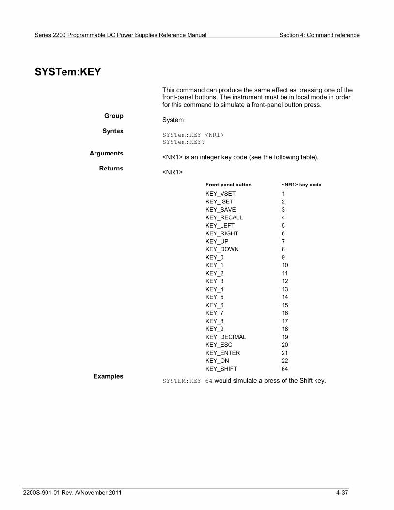
Series 2200 Programmable DC Power Supplies Reference Manual Section 4: Command reference
2200S-901-01 Rev. A/November 2011 4-37
SYSTem:KEY
This command can produce the same effect as pressing one of the front-panel buttons. The instrument must be in local mode in order for this command to simulate a front-panel button press.
Group System
Syntax SYSTem:KEY <NR1> SYSTem:KEY?
Arguments <NR1> is an integer key code (see the following table).
Returns <NR1>
Front-panel button <NR1> key code
KEY_VSET 1 KEY_ISET 2 KEY_SAVE 3 KEY_RECALL 4 KEY_LEFT 5 KEY_RIGHT 6 KEY_UP 7 KEY_DOWN 8 KEY_0 9 KEY_1 10 KEY_2 11 KEY_3 12 KEY_4 13 KEY_5 14 KEY_6 15 KEY_7 16 KEY_8 17 KEY_9 18 KEY_DECIMAL 19 KEY_ESC 20 KEY_ENTER 21 KEY_ON 22 KEY_SHIFT 64
Examples SYSTEM:KEY 64 would simulate a press of the Shift key.

Section 4: Command reference Series 2200 Programmable DC Power Supplies Reference Manual
4-38 2200S-901-01 Rev. A/November 2011
SYSTem:LOCal (no query form)
This command sets the power supply for control from the front-panel.
Group System
Syntax SYSTem:LOCal
Related Commands SYSTem:LOCal (no query form) (on page 4-38)
SYSTem:RWLock (no query form) (on page 4-39)
Examples SYS:LOC
SYSTem:POSetup
This command determines how the power supply initializes when its power switch is turned on. This command configures the instrument to power up with default settings, or power up with the settings that were in effect when the instrument was turned off.
Group System
Syntax SYSTem:POSetup {RST|RCL0}
SYSTem:POSetup?
Arguments RST: initializes the power supply to default settings after a power cycle.
RCL0: saves the most recent settings and restores these after a power cycle.
Returns RST: default settings are applied after a power cycle.
RCL0: most recent settings are saved and restored after a power cycle.
Examples SYST:POS RST
SYSTEM:POSETUP? might respond with RST, which would indicate that the power supply is configured to restore the power supply to default settings when it powers up.
Series 2200 Programmable DC Power Supplies Reference Manual Section 4: Command reference
2200S-901-01 Rev. A/November 2011 4-39
SYSTem:REMote (no query form)
This command sets the power supply to remote control mode.
Group System
Syntax SYSTem:REMote
Related Commands SYSTem:LOCal (no query form) (on page 4-38)
SYSTem:RWLock (no query form) (on page 4-39)
Arguments None.
Examples SYSTEM:REMOTE
SYSTem:RWLock (no query form)
If the power supply is in remote mode, this command locks out the front panel LOCAL button. This command has no effect if the instrument is in local mode.
Group System
Syntax SYSTem:RWLock
Related Commands SYSTem:REMote (no query form) (on page 4-39)
SYSTem:LOCal (no query form) (on page 4-38)
Arguments None
Examples SYSTEM:RWLOCK
SYSTem:VERSion? (query only)
This command returns SCPI version of the instrument.
Group System
Syntax SYSTem:VERSion?
Returns <NR2> is the software version of the power supply.
Section 4: Command reference Series 2200 Programmable DC Power Supplies Reference Manual
4-40 2200S-901-01 Rev. A/November 2011
Examples SYSTEM:VERSION? might return 1991.0, which is the SCPI version number.
*TRG (no query form)
This command generates a trigger event.
Group Trigger
Syntax *TRG
Related Commands TRIGger[:IMMediate] (no query form) (on page 4-40)
Examples *TRG
TRIGger[:IMMediate] (no query form)
This command forces an immediate trigger event.
Group Trigger
Syntax RIGger[:IMMediate]
Related Commands *TRG (no query form) (on page 4-40)
Arguments None
Examples TRIGGER

Series 2200 Programmable DC Power Supplies Reference Manual Section 4: Command reference
2200S-901-01 Rev. A/November 2011 4-41
TRIGger:SOURce
This command sets the source of trigger events.
Group Trigger
Syntax TRIGger:SOURce {MANual|IMMediate|EXTernal|BUS}
TRIGger:SOURce?
Related Commands [SOURce:]DIGital:FUNCtion (on page 4-12)
*TRG (no query form) (on page 4-40) TRIGger[:IMMediate] (no query form) (on page 4-40)
Arguments MANual: When this value is sent, the power supply will wait for a trigger from the front-panel. Press Shift + Trigger (3) to trigger the power supply.
IMMediate: When this value is sent, the power supply will wait for a TRIgger:IMMediate bus command.
EXTernal: When this value is sent, the power supply can be triggered with a
TTL pulse applied to pin 1 of the terminal connector in the rear. The pulse width should be at least 5 ms.
BUS: When this value is sent, the power supply can be triggered by sending a *TRG or TRIgger:IMMediate command to the power supply.
Examples TRIGGER:SOURCE BUS
*TST? (query only)
Initiates a self-test and reports any errors.
Group Diagnostic
Syntax *TST?
Returns <NR1>
where:
<NR1>= 0 indicates that the self-test completed with no errors.
<NR1> not equal to 0 indicates that the self test detected an error. Self test code descriptions are described in Self test errors (on page C-11).

Section 4: Command reference Series 2200 Programmable DC Power Supplies Reference Manual
4-42 2200S-901-01 Rev. A/November 2011
*WAI (no query form)
This command prevents the instrument from executing further commands or queries until all pending commands are complete.
Group Synchronization
Syntax *WAI
Examples *WAI
Programming examples This topic provides the following programming examples:

Series 2200 Programmable DC Power Supplies Reference Manual Section 4: Command reference
2200S-901-01 Rev. A/November 2011 4-43
Example 1 This example is written in the C programming language, the Virtual Instrument Software Architecture (VISA) standard can be used. It demonstrates basic communication with the power supply and error checking. The program establishes communication with the power supply, and puts it into remote mode. It then initializes the voltage and current and turns the output on. It sends new values for the voltage and current, and reads back the actual meter values before turning off the power supply output and closing communications. // pws_visa.cpp
//
#include "stdafx.h"
#include <visa.h>
#include <stdio.h>
#include <string.h>
#include <time.h>
#include <conio.h>
#include <stdlib.h>
ViSession defaultRM; //Resource manager id
ViSession PWS4000; //Identifies the power supply
long ErrorStatus;
char commandString[256];
char ReadBuffer[256];
void OpenPort();
void SendSCPI(char* pString);
void CheckError(char* pMessage);
void delay(clock_t wait);
void ClosePort();
int main(int argc, _TCHAR* argv[])
{
double voltage;
char Buffer[256];
double current;
OpenPort();
//Query the power supply id, read response and print it
sprintf(Buffer, "*IDN?");
SendSCPI(Buffer);
printf("Instrument identification string:%s \n", Buffer);
SendSCPI("*RST"); //reset the power supply
SendSCPI("CURRENT 0.1A"); //set the current to 0.1A
SendSCPI("VOLTAGE 3V"); //set the voltage to 3V
SendSCPI("OUTPUT 1"); // turn output on
voltage=5.0;
current=0.2;
printf("Setting voltage(V) & current(A): %f,%f \n",
voltage, current);
ErrorStatus = viPrintf(PWS4000,"VOLT %f\n",voltage); //set
the output voltage
CheckError("Unable to set voltage");
ErrorStatus = viPrintf(PWS4000,"CURRENT %f\n",current);
//set the output current
CheckError("Unable to set current");
ErrorStatus = viPrintf(PWS4000,"MEASURE:VOLTAGE?\n");
//measure the output voltage
CheckError("Unable to write the device");
ErrorStatus = viScanf(PWS4000,"%f",&voltage); //retrieve

Section 4: Command reference Series 2200 Programmable DC Power Supplies Reference Manual
4-44 2200S-901-01 Rev. A/November 2011
reading
CheckError("Unable to read voltage");
ErrorStatus = viPrintf(PWS4000,"MEASURE:CURRENT?\n");
//measure the output current
CheckError("Unable to write the device");
ErrorStatus = viScanf(PWS4000,"%f",¤t); //retrieve
reading
CheckError("Unable to read current");
printf("Measured voltage(V) & current(A): %f,%f \n",
voltage, current);
SendSCPI("OUTPUT 0"); //turn output off
ClosePort();
while(1);
//return 0;
}
void OpenPort()
{
//Open communication session with the power supply, and
put the power supply in remote
ErrorStatus = viOpenDefaultRM(& defaultRM);
ErrorStatus =viOpen(defaultRM,
"USB0::0X0699::0X0391::006002206573001001::INSTR",0,0,&PWS4000);
CheckError("Unable to open the port");
SendSCPI("SYSTEM:REMOTE");
}
void SendSCPI(char* pString)
{
char* pdest;
strcpy(commandString,pString);
strcat(commandString, "\n");
ErrorStatus = viPrintf(PWS4000, commandString);
CheckError("Can't Write to Power Supply");
pdest = strchr(commandString, '?'); //Search for query
command
if (pdest != NULL)
{
ErrorStatus = viBufRead(PWS4000, (ViBuf)ReadBuffer,
sizeof(ReadBuffer), VI_NULL);
CheckError("Can't read from driver");
strcpy(pString, ReadBuffer);
}
}
void ClosePort()
{
viClose(PWS4000);
viClose(defaultRM);
}
void CheckError(char* pMessage)
{
if(ErrorStatus != VI_SUCCESS)
{
printf("\n %s",pMessage);
ClosePort();
exit(0);
}
}
void delay(clock_t wait)

Series 2200 Programmable DC Power Supplies Reference Manual Section 4: Command reference
2200S-901-01 Rev. A/November 2011 4-45
{
clock_t goal;
goal = wait + clock();
while(goal > clock());
}
Example 2 This example shows a command sequence that configures a three-step list to execute once in continuous mode. It saves the list in location 1, and then places the instrument in list mode and runs the list. SYSTEM:REMOTE
*RST
TRIGGER:SOURCE BUS
LIST:MODE CONT
LIST:COUNT ONCE
LIST:STEP 3
LIST:VOLT 1,2V
LIST:CURRENT 1,1.0A
LIST:WIDTH 1,5s
LIST:VOLT 2,4V
LIST:CURRENT 2,1.0A
LIST:WIDTH 2,10s
LIST:VOLT 3,0V
LIST:CURRENT 3,0.1A
LIST:WIDTH 3,2s
LIST:SAVE 1
FUNCTION:MODE LIST
OUTPUT ON
TRIGGER IMMEDIATE
Example 3 This example shows a command sequence that configures a two-step list to execute 20 times. It saves the list in location 1, and then places the instrument in list mode and runs the list. SYSTEM:REMOTE
*RST
TRIGGER:SOURCE BUS
LIST:MODE CONT
LIST:COUNT 20
LIST:STEP 2
LIST:VOLTAGE 1,5V
LIST:CURRent 1,1.0A
LIST:WIDTH 1,10s
LIST:VOLTAGE 2,5.5V
LIST:CURRent 2,1.0A
LIST:WIDTH 2,5s
LIST:SAVE 1
FUNCTION:MODE LIST
OUTPUT ON
TRIGGER:IMMEDIATE

Section 4: Command reference Series 2200 Programmable DC Power Supplies Reference Manual
4-46 2200S-901-01 Rev. A/November 2011
Example 4 This example is written in the C programming language; NI VISA can be used. The program demonstrates setting up and executing a list. It shows how to use the Operation Condition Register to determine when the list has finished executing. // pws_visa.c
//
#undef MICROSOFT // Change this to #define if Microsoft
#ifdef MICROSOFT
#include “stdafx.h”
#include <conio.h>
#else
typedef char_TCHAR;
#endif
#include <visa.h>
#include <stdio.h>
#include <string.h>
#include <time.h>
#include <stdlib.h>
ViSession defaultRM; //Resource manager id
ViSession PWS4000; //Identifies the power supply
long ErrorStatus;
char commandString[256];
char ReadBuffer[256];
//
// Some compilers do not require that void arguments be
declared, however, all should accept declaration of
// void argument lists.
//
void OpenPort(); // void added
void SendSCPI(char* pString);
void CheckError(char* pMessage);
void delay(clock_t wait);
void ClosePort(); // void added
int main(int argc, _TCHAR* argv[])
{
double voltage;
char Buffer[256];
double current;
int OPERreg,i;
float meas_voltage, meas_current;
int List_count=10;
int List_step =3;
double List_Volt[3]= {3.0, 4.0, 6.0};
double List_Curr[3] = {0.1, 0.1, 0.1};
int List_Time[3]= {1,2,3};
}
OpenPort();
//Query the power supply id, read response and print it
sprintf(Buffer, "*IDN?");
SendSCPI(Buffer);
printf("Instrument identification string:%s \n", Buffer);
SendSCPI("*RST"); //reset the power supply
delay(100)
SendSCPI("CURRENT 0.1A"); //set the current to 0.1A

Series 2200 Programmable DC Power Supplies Reference Manual Section 4: Command reference
2200S-901-01 Rev. A/November 2011 4-47
SendSCPI("VOLTAGE 0V"); //set the voltage to 0V
SendSCPI("OUTPUT 1"); // turn output on
SendSCPI("TRIGGER:SOURCE BUS"); //set trigger source to bus
/* configure the list*/
SendSCPI("LIST:MODE CONT"); //set the list mode to
continuous
ErrorStatus = viPrintf(PWS4000,"LIST:COUNT
%d\n",List_count); //set the list count
CheckError("Unable to set list count");
ErrorStatus = viPrintf(PWS4000,"LIST:STEP %d\n",List_step);
//set the list step
CheckError("Unable to set list step");
/*set the list voltage, current and time */
for(i = 1; i<= List_step; i+=1)
{
ErrorStatus = viPrintf(PWS4000,"LIST:CURRent %d, %f\n", i,
List_Curr[i-1]); //set the step current
CheckError("Unable to set list current");
ErrorStatus = viPrintf(PWS4000,"LIST:VOLTage %d, %f\n",
i, List_Volt[i-1]); //set the step voltage
CheckError("Unable to set list voltage");
ErrorStatus = viPrintf(PWS4000,"LIST:WIDTH %d, %f\n", i,
List_Time[i-1]); //set the output voltage
CheckError("Unable to set list time");
}
SendSCPI("LIST:SAVE 1"); // save the list
SendSCPI("FUNCTION:MODE LIST"); // set the power supply in
list mode
SendSCPI("TRIGGER"); // trigger the list
printf("List is running\n");
/*Check the state of bit 5 of the Operation Condition
Register to determine if list is still running. */
do
{
delay(500);
ErrorStatus = viPrintf(PWS4000,
"STATus:OPERation:CONDition?\n");
CheckError("Unable to write the device");
ErrorStatus = viScanf(PWS4000,"%d",&OPERreg);
} while (OPERreg & 0x20);
printf("List finished\n");
ClosePort();
while(1); //return 0;
}
void OpenPort()
{
//Open communication session with the power supply
ErrorStatus = viOpenDefaultRM(& defaultRM);
ErrorStatus =viOpen(defaultRM,
"USB0::0X0699::0X0391::006002206573001001::INSTR",0,0,&PWS4000);
CheckError("Unable to open the port");
SendSCPI("SYSTEM:REMOTE");
}
void SendSCPI(char* pString)
{
char* pdest;
strcpy(commandString,pString);

Section 4: Command reference Series 2200 Programmable DC Power Supplies Reference Manual
4-48 2200S-901-01 Rev. A/November 2011
strcat(commandString, "\n");
ErrorStatus = viPrintf(PWS4000, commandString);
CheckError("Can't Write to Power Supply");
pdest = strchr(commandString, '?'); //Search for query
command
if (pdest != NULL)
{
ErrorStatus = viBufRead(PWS4000, (ViBuf)ReadBuffer,
sizeof(ReadBuffer), VI_NULL);
CheckError("Can't read from driver");
strcpy(pString, ReadBuffer);
}
}
void ClosePort()
{
viClose(PWS4000);
viClose(defaultRM);
}
void CheckError(char* pMessage)
{
if(ErrorStatus != VI_SUCCESS)
{
printf("\n %s",pMessage);
ClosePort();
exit(0);
}
}
void delay(clock_t wait)
{
clock_t goal;
goal = wait + clock();
while(goal > clock());
}

In this section:
What to do if the power supply does not turn on ...................... 5-1
What to do if the power supply does not turn on To solve problems you might encounter when turning on the instrument, follow these steps:
1. Verify that there is AC power to the power supply. First, check that the AC power cord is firmly plugged into the power connector on the rear panel of the power supply. You should also make sure that the AC power source you plugged the power supply into is energized. Then, check that the power supply is turned on.
2. Verify the power-line voltage settings. Check that the line voltage selector switch on the bottom of the instrument is set to the proper value for your country (110 VAC or 220 VAC). Change the voltage setting if it is not correct.
Under certain circumstances, powering the instrument from a mains voltage for which it is not configured can cause the mains fuse to open.
3. Verify that the correct power-line fuse is installed. If the fuse is damaged, replace the fuse for your power supply. If you set the line selection to 110 V, use a 5 A, TH 250 V fuse. If you set the line selection to 220 V, use a 2.5 A, TH 250 V fuse.
4. If you need more help, see Additional Series 2200 information (on page 6-1) for information.
Section 5
Troubleshooting guide

In this section:
Additional Series 2200 information ........................................... 6-1
Additional Series 2200 information This manual has prepared you to start using your new Series 2200 instrument.
For additional information on the Series 2200, refer to:
The Product Information CD-ROM (ships with the product): Contains software tools, drivers, andproduct documentation.
information; from the website, you can access: The Knowledge Center, which contains the following handbooks:
The Low Level Measurements Handbook: Precision DC Current, Voltage, and ResistanceMeasurements
Switching Handbook: A Guide to Signal Switching in Automated Test Systems Application notes Updated drivers
Your local Field Applications Engineer can help you with product selection, configuration, andusage. Check the website for contact information.
Section 6
Next Steps

Section 6: Next Steps Series 2200 Programmable DC Power Supplies Reference Manual
6-2 2200S-901-01 Rev. A/November 2011

In this appendix:
Cleaning ................................................................................... A-1
Cleaning Inspect the power supply as often as operating conditions require. To clean the exterior surface, perform the following steps:
1. Remove loose dust on the outside of the power supply with a lint-free cloth. Use care to avoid scratching the display.
2. Use a soft cloth dampened with water to clean the power supply. Use an aqueous solution of 75% isopropyl alcohol for more efficient cleaning.
To avoid damage to the surface of the power supply, do not use any abrasive or chemical cleaning agents.
Appendix A
Maintenance

Appendix A: Maintenance Series 2200 Programmable DC Power Supplies Reference Manual
A-2 2200S-901-01 Rev. A/November 2011

In this appendix:
Performance verification ........................................................... B-1 Performance verification procedures ...................................... B-11
Performance verification This topic contains performance verification procedures. Additional test equipment is required to complete the verification procedures. (See Test equipment (on page B-12).
These procedures cover the 2200-20-5, 2200-30-5, 2200-32-3, 2200-60-2, and 2200-72-1 models. Ignore procedures that do not apply to the specific model you are testing.
Print the Test record (on page B-2), and use it to record the performance test results for your power supply.
Completion of the performance verification procedure does not update the stored time and date of the latest successful adjustment. The date and time are updated only when the factory adjustment procedures are successfully completed.
The performance verification procedures verify the performance of your instrument. They do not adjust your instrument. If your instrument fails any of the performance verification tests, you should contact Keithley service.
Appendix B
Calibration
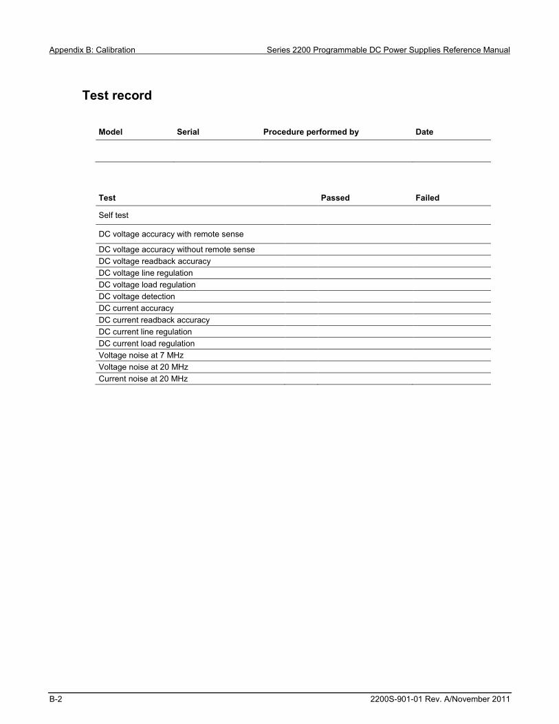
Appendix B: Calibration Series 2200 Programmable DC Power Supplies Reference Manual
B-2 2200S-901-01 Rev. A/November 2011
Test record
Model Serial Procedure performed by Date
Test Passed Failed
Self test
DC voltage accuracy with remote sense
DC voltage accuracy without remote sense DC voltage readback accuracy DC voltage line regulation DC voltage load regulation DC voltage detection DC current accuracy DC current readback accuracy DC current line regulation DC current load regulation Voltage noise at 7 MHz Voltage noise at 20 MHz Current noise at 20 MHz

Series 2200 Programmable DC Power Supplies Reference Manual Appendix B: Calibration
2200S-901-01 Rev. A/November 2011 B-3
DC voltage accuracy with remote sense
Instrument DUT voltage Test current Min Measured Max 0% Test Voltage
2200-20-5 0 V 2.5 A -0.0030 V __________ 0.0030 V
2200-30-5 0 V 2.5 A -0.0030 V __________ 0.0030 V 2200-32-3 0 V 1.5 A -0.0030 V __________ 0.0030 V 2200-60-2 0 V 1.25 A -0.0060 V __________ 0.0060 V 2200-70-1 0 V 0.63 A -0.0060 V __________ 0.0060 V 25% Test Voltage 2200-20-5 5 V 2.5 A 4.9955 V __________ 5.0045 V 2200-30-5 7.5 V 2.5 A 7.49475 V __________ 7.50525 V 2200-32-3 8 V 1.5 A 7.9946 V __________ 8.0054 V 2200-60-2 15 V 1.25 A 14.9895 V __________ 15.0105 V 2200-70-1 18 V 0.63 A 17.9886 V __________ 18.0114 V 50% Test Voltage 2200-20-5 10 V 2.5 A 9.9940 V __________ 10.0060 V 2200-30-5 15 V 2.5 A 14.9925 V __________ 15.0075 V 2200-32-3 16 V 1.5 A 15.9922 V __________ 16.0078 V 2200-60-2 30 V 1.25 A 29.9850 V __________ 30.0150 V
2200-70-1 36 V 0.63 A 35.9832 V __________ 36.0168 V 75% Test Voltage 2200-20-5 15 V 2.5 A 14.9925 V __________ 15.00750 V 2200-30-5 22.5 V 2.5 A 22.49025 V __________ 22.50975 V 2200-32-3 24 V 1.5 A 23.9898 V __________ 24.0102 V 2200-60-2 45 V 1.25 A 44.9805 V __________ 45.0195 V 2200-70-1 54 V 0.63 A 53.9778 V __________ 54.0222 V 100% Test Voltage 2200-20-5 20 V 2.5 A 19.9910 V __________ 20.0090 V 2200-30-5 30 V 2.5 A 29.9880 V __________ 30.0120 V 2200-32-3 32 V 1.5 A 31.9874 V __________ 32.0126 V 2200-60-2 60 V 1.25 A 59.9760 V __________ 60.0240 V 2200-70-1 72 V 0.63 A 71.9724 V __________ 72.0276 V
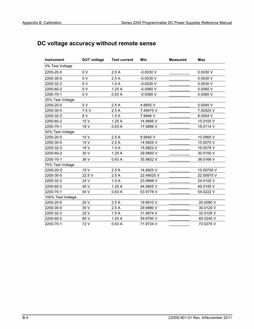
Appendix B: Calibration Series 2200 Programmable DC Power Supplies Reference Manual
B-4 2200S-901-01 Rev. A/November 2011
DC voltage accuracy without remote sense
Instrument DUT voltage Test current Min Measured Max 0% Test Voltage
2200-20-5 0 V 2.5 A -0.0030 V __________ 0.0030 V
2200-30-5 0 V 2.5 A -0.0030 V __________ 0.0030 V 2200-32-3 0 V 1.5 A -0.0030 V __________ 0.0030 V 2200-60-2 0 V 1.25 A -0.0060 V __________ 0.0060 V 2200-70-1 0 V 0.63 A -0.0060 V __________ 0.0060 V 25% Test Voltage 2200-20-5 5 V 2.5 A 4.9955 V __________ 5.0045 V 2200-30-5 7.5 V 2.5 A 7.49475 V __________ 7.50525 V 2200-32-3 8 V 1.5 A 7.9946 V __________ 8.0054 V 2200-60-2 15 V 1.25 A 14.9895 V __________ 15.0105 V 2200-70-1 18 V 0.63 A 17.9886 V __________ 18.0114 V 50% Test Voltage 2200-20-5 10 V 2.5 A 9.9940 V __________ 10.0060 V 2200-30-5 15 V 2.5 A 14.9925 V __________ 15.0075 V 2200-32-3 16 V 1.5 A 15.9922 V __________ 16.0078 V 2200-60-2 30 V 1.25 A 29.9850 V __________ 30.0150 V
2200-70-1 36 V 0.63 A 35.9832 V __________ 36.0168 V 75% Test Voltage 2200-20-5 15 V 2.5 A 14.9925 V __________ 15.00750 V 2200-30-5 22.5 V 2.5 A 22.49025 V __________ 22.50975 V 2200-32-3 24 V 1.5 A 23.9898 V __________ 24.0102 V 2200-60-2 45 V 1.25 A 44.9805 V __________ 45.0195 V 2200-70-1 54 V 0.63 A 53.9778 V __________ 54.0222 V 100% Test Voltage 2200-20-5 20 V 2.5 A 19.9910 V __________ 20.0090 V 2200-30-5 30 V 2.5 A 29.9880 V __________ 30.0120 V 2200-32-3 32 V 1.5 A 31.9874 V __________ 32.0126 V 2200-60-2 60 V 1.25 A 59.9760 V __________ 60.0240 V 2200-70-1 72 V 0.63 A 71.9724 V __________ 72.0276 V

Series 2200 Programmable DC Power Supplies Reference Manual Appendix B: Calibration
2200S-901-01 Rev. A/November 2011 B-5
DC voltage readback accuracy
Instrument DUT voltage Test current Measured voltage
Voltage readout
Absolute difference
Maximum difference
0% Test Voltage
2200-20-5 0 V 2.5 A __________ __________ __________ 0.0030 V
2200-30-5 0 V 2.5 A __________ __________ __________ 0.0025 V 2200-32-3 0 V 1.5 A __________ __________ __________ 0.0030 V 2200-60-2 0 V 1.25 A __________ __________ __________ 0.0060 V 2200-70-1 0 V 0.63 A __________ __________ __________ 0.0050 V 25% Test Voltage 2200-20-5 5 V 2.5 A __________ __________ __________ 0.0040 V 2200-30-5 7.5 V 2.5 A __________ __________ __________ 0.0040 V 2200-32-3 8 V 1.5 A __________ __________ __________ 0.0046 V 2200-60-2 15 V 1.25 A __________ __________ __________ 0.0090 V 2200-70-1 18 V 0.63 A __________ __________ __________ 0.0086 V 50% Test Voltage 2200-20-5 10 V 2.5 A __________ __________ __________ 0.0050 V 2200-30-5 15 V 2.5 A __________ __________ __________ 0.0050 V 2200-32-3 16 V 1.5 A __________ __________ __________ 0.0062 V 2200-60-2 30 V 1.25 A __________ __________ __________ 0.0120 V
2200-70-1 36 V 0.63 A __________ __________ __________ 0.0122 V 75% Test Voltage 2200-20-5 15 V 2.5 A __________ __________ __________ 0.0060 V 2200-30-5 22.5 V 2.5 A __________ __________ __________ 0.0070 V 2200-32-3 24 V 1.5 A __________ __________ __________ 0.0078 V 2200-60-2 45 V 1.25 A __________ __________ __________ 0.0150 V 2200-70-1 54 V 0.63 A __________ __________ __________ 0.0158 V 100% Test Voltage 2200-20-5 20 V 2.5 A __________ __________ __________ 0.0070 V 2200-30-5 30 V 2.5 A __________ __________ __________ 0.0085 V 2200-32-3 32 V 1.5 A __________ __________ __________ 0.0094 V 2200-60-2 60 V 1.25 A __________ __________ __________ 0.0180 V 2200-70-1 72 V 0.63 A __________ __________ __________ 0.0194 V

Appendix B: Calibration Series 2200 Programmable DC Power Supplies Reference Manual
B-6 2200S-901-01 Rev. A/November 2011
DC voltage line regulation
Instrument Min line Max line Nom - Min Max - Nom Largest Max value 2200-20-5 __________ __________ __________ __________ __________ 0.0080 V
2200-30-5 __________ __________ __________ __________ __________ 0.0100 V 2200-32-3 __________ __________ __________ __________ __________ 0.0104 V 2200-60-2 __________ __________ __________ __________ __________ 0.0160 V 2200-70-1 __________ __________ __________ __________ __________ 0.0184 V
DC voltage load regulation
Instrument Min load Ref load Max load Ref - Min Max - Ref
(Max - Ref) / 0.98
Largest Max value
2200-20-5 ________ ________ ________
________
________
________ ________ 0.00800 V
2200-30-5 ________ ________ ________
________
________
________ ________ 0.01000 V
2200-32-3 ________ ________ ________
________
________
________ ________ 0.01040 V
2200-60-2 ________ ________ ________
________
________
________ ________ 0.01600 V
2200-70-1 ________ ________ ________
________
________
________ ________ 0.01840 V
DC overvoltage detection
Instrument
Min trigger voltage Measured trigger voltage Max trigger voltage
2200-20-5 4.75 V ___________ 5.525 V
2200-30-5 4.75 V ___________ 5.525 V 2200-32-3 4.75 V ___________ 5.525 V 2200-60-2 4.75 V ___________ 5.525 V 2200-70-1 4.75 V ___________ 5.525 V
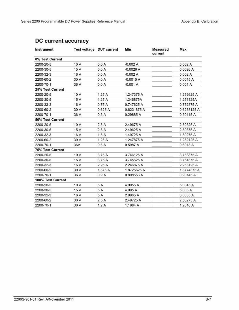
Series 2200 Programmable DC Power Supplies Reference Manual Appendix B: Calibration
2200S-901-01 Rev. A/November 2011 B-7
DC current accuracy Instrument Test voltage DUT current Min Measured
current Max
0% Test Current 2200-20-5 10 V 0.0 A -0.002 A __________ 0.002 A 2200-30-5 15 V 0.0 A -0.0026 A __________ 0.0026 A 2200-32-3 16 V 0.0 A -0.002 A __________ 0.002 A 2200-60-2 30 V 0.0 A -0.0015 A __________ 0.0015 A 2200-70-1 36 V 0.0 A -0.001 A __________ 0.001 A 25% Test Current 2200-20-5 10 V 1.25 A 1.247375 A __________ 1.252625 A 2200-30-5 15 V 1.25 A 1.246875A __________ 1.253125A 2200-32-3 16 V 0.75 A 0.747625 A __________ 0.752375 A 2200-60-2 30 V 0.625 A 0.6231875 A __________ 0.6268125 A 2200-70-1 36 V 0.3 A 0.29885 A __________ 0.30115 A 50% Test Current 2200-20-5 10 V 2.5 A 2.49675 A __________ 2.50325 A 2200-30-5 15 V 2.5 A 2.49625 A __________ 2.50375 A 2200-32-3 16 V 1.5 A 1.49725 A __________ 1.50275 A 2200-60-2 30 V 1.25 A 1.247875 A __________ 1.252125 A 2200-70-1 36V 0.6 A 0.5987 A __________ 0.6013 A 75% Test Current 2200-20-5 10 V 3.75 A 3.746125 A __________ 3.753875 A 2200-30-5 15 V 3.75 A 3.745625 A __________ 3.754375 A 2200-32-3 16 V 2.25 A 2.246875 A __________ 2.253125 A 2200-60-2 30 V 1.875 A 1.8725625 A __________ 1.8774375 A 2200-70-1 36 V 0.9 A 0.898553 A __________ 0.90145 A 100% Test Current 2200-20-5 10 V 5 A 4.9955 A __________ 5.0045 A 2200-30-5 15 V 5 A 4.995 A __________ 5.005 A 2200-32-3 16 V 5 A 2.9965 A __________ 3.0035 A 2200-60-2 30 V 2.5 A 2.49725 A __________ 2.50275 A 2200-70-1 36 V 1.2 A 1.1984 A __________ 1.2016 A
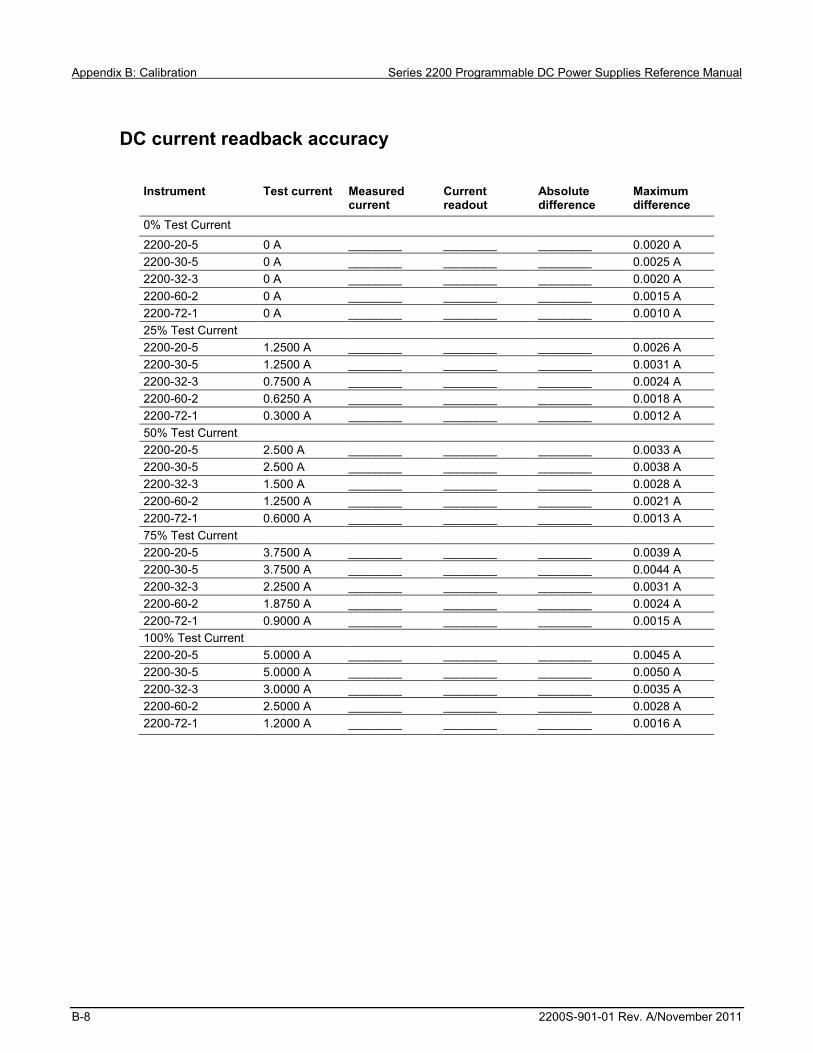
Appendix B: Calibration Series 2200 Programmable DC Power Supplies Reference Manual
B-8 2200S-901-01 Rev. A/November 2011
DC current readback accuracy
Instrument Test current Measured current
Current readout
Absolute difference
Maximum difference
0% Test Current
2200-20-5 0 A ________ ________ ________ 0.0020 A 2200-30-5 0 A ________ ________ ________ 0.0025 A 2200-32-3 0 A ________ ________ ________ 0.0020 A 2200-60-2 0 A ________ ________ ________ 0.0015 A 2200-72-1 0 A ________ ________ ________ 0.0010 A 25% Test Current 2200-20-5 1.2500 A ________ ________ ________ 0.0026 A 2200-30-5 1.2500 A ________ ________ ________ 0.0031 A 2200-32-3 0.7500 A ________ ________ ________ 0.0024 A 2200-60-2 0.6250 A ________ ________ ________ 0.0018 A 2200-72-1 0.3000 A ________ ________ ________ 0.0012 A 50% Test Current 2200-20-5 2.500 A ________ ________ ________ 0.0033 A 2200-30-5 2.500 A ________ ________ ________ 0.0038 A 2200-32-3 1.500 A ________ ________ ________ 0.0028 A 2200-60-2 1.2500 A ________ ________ ________ 0.0021 A 2200-72-1 0.6000 A ________ ________ ________ 0.0013 A 75% Test Current 2200-20-5 3.7500 A ________ ________ ________ 0.0039 A 2200-30-5 3.7500 A ________ ________ ________ 0.0044 A 2200-32-3 2.2500 A ________ ________ ________ 0.0031 A 2200-60-2 1.8750 A ________ ________ ________ 0.0024 A 2200-72-1 0.9000 A ________ ________ ________ 0.0015 A 100% Test Current 2200-20-5 5.0000 A ________ ________ ________ 0.0045 A 2200-30-5 5.0000 A ________ ________ ________ 0.0050 A 2200-32-3 3.0000 A ________ ________ ________ 0.0035 A 2200-60-2 2.5000 A ________ ________ ________ 0.0028 A 2200-72-1 1.2000 A ________ ________ ________ 0.0016 A

Series 2200 Programmable DC Power Supplies Reference Manual Appendix B: Calibration
2200S-901-01 Rev. A/November 2011 B-9
DC current line regulation
Instrument Test voltage
Min line Max line Nom line Nom - Min Max - Nom
Largest Max value
2200-20-5 10 V ______ ________ ________ ________ ________ ________ ________ 0.0052 A
2200-30-5 15 V ______ ________ ________ ________ ________ ________ ________ 0.0052 A 2200-32-3 16 V ______ ________ ________ ________ ________ ________ ________ 0.0032 A 2200-60-2 30 V ______ ________ ________ ________ ________ ________ ________ 0.0026 A 2200-72-1 36 V ______ ________ ________ ________ ________ ________ ________ 0.0014 A
DC current load regulation
Instrument Meas @ min volts
Meas @ ref volts
Meas @ max volts
Ref Min Max - Ref Largest Maximum difference
2200-20-5 ________ ________ ________ ________ ________ ________ 0.0021 A 2200-30-5 _______ ________ ________ ________ ________ ________ 0.0035 A 2200-32-3 ________ ________ ________ ________ ________ ________ 0.0013 A 2200-60-2 ________ ________ ________ ________ ________ ________ 0.0016 A 2200-72-1 ________ ________ ________ ________ ________ ________ 0.00098 A
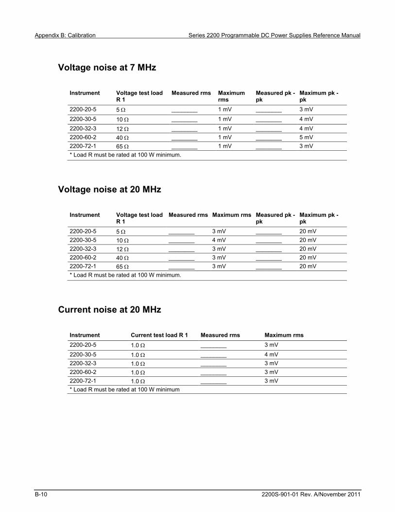
Appendix B: Calibration Series 2200 Programmable DC Power Supplies Reference Manual
B-10 2200S-901-01 Rev. A/November 2011
Voltage noise at 7 MHz
Instrument Voltage test load R 1
Measured rms Maximum rms
Measured pk -pk
Maximum pk -pk
2200-20-5 5 ________ 1 mV ________ 3 mV
2200-30-5 10 ________ 1 mV ________ 4 mV 2200-32-3 12 ________ 1 mV ________ 4 mV 2200-60-2 40 ________ 1 mV ________ 5 mV 2200-72-1 65 ________ 1 mV ________ 3 mV * Load R must be rated at 100 W minimum.
Voltage noise at 20 MHz
Instrument Voltage test load R 1
Measured rms Maximum rms Measured pk -pk
Maximum pk -pk
2200-20-5 5 ________ 3 mV ________ 20 mV 2200-30-5 10 ________ 4 mV ________ 20 mV 2200-32-3 12 ________ 3 mV ________ 20 mV 2200-60-2 40 ________ 3 mV ________ 20 mV 2200-72-1 65 ________ 3 mV ________ 20 mV * Load R must be rated at 100 W minimum.
Current noise at 20 MHz
Instrument Current test load R 1 Measured rms Maximum rms 2200-20-5 1.0 ________ 3 mV
2200-30-5 1.0 ________ 4 mV 2200-32-3 1.0 ________ 3 mV 2200-60-2 1.0 ________ 3 mV 2200-72-1 1.0 ________ 3 mV * Load R must be rated at 100 W minimum
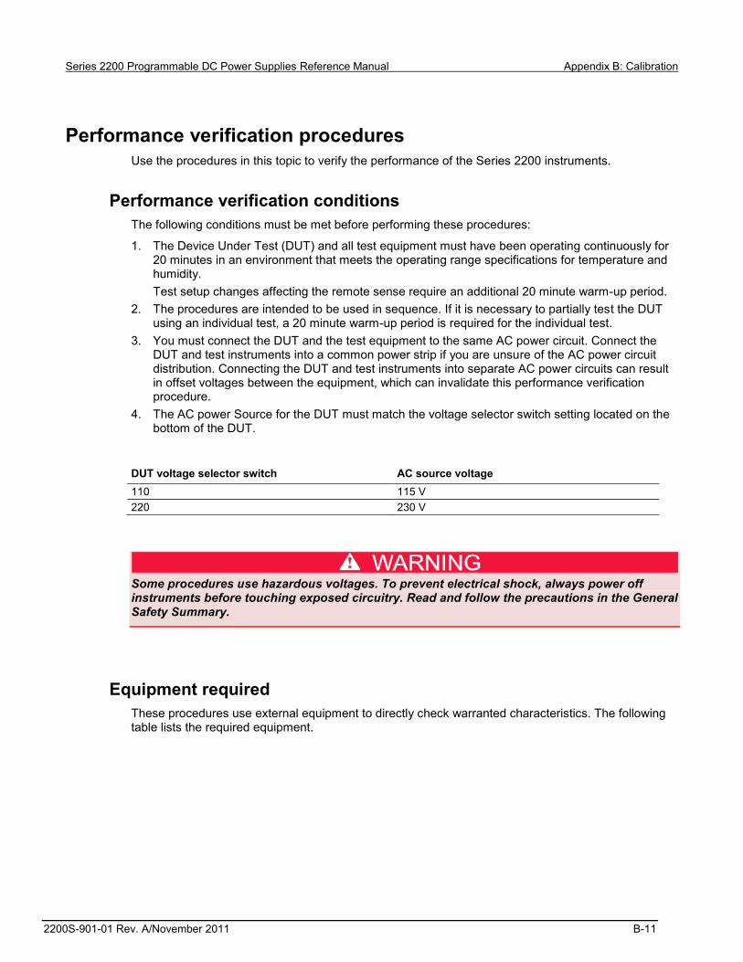
Series 2200 Programmable DC Power Supplies Reference Manual Appendix B: Calibration
2200S-901-01 Rev. A/November 2011 B-11
Performance verification procedures Use the procedures in this topic to verify the performance of the Series 2200 instruments.
Performance verification conditions The following conditions must be met before performing these procedures:
1. The Device Under Test (DUT) and all test equipment must have been operating continuously for 20 minutes in an environment that meets the operating range specifications for temperature and humidity. Test setup changes affecting the remote sense require an additional 20 minute warm-up period.
2. The procedures are intended to be used in sequence. If it is necessary to partially test the DUT using an individual test, a 20 minute warm-up period is required for the individual test.
3. You must connect the DUT and the test equipment to the same AC power circuit. Connect the DUT and test instruments into a common power strip if you are unsure of the AC power circuit distribution. Connecting the DUT and test instruments into separate AC power circuits can result in offset voltages between the equipment, which can invalidate this performance verification procedure.
4. The AC power Source for the DUT must match the voltage selector switch setting located on the bottom of the DUT.
DUT voltage selector switch AC source voltage 110 115 V 220 230 V
Some procedures use hazardous voltages. To prevent electrical shock, always power off instruments before touching exposed circuitry. Read and follow the precautions in the General Safety Summary.
Equipment required These procedures use external equipment to directly check warranted characteristics. The following table lists the required equipment.

Appendix B: Calibration Series 2200 Programmable DC Power Supplies Reference Manual
B-12 2200S-901-01 Rev. A/November 2011
Test equipment
Item Connectors Minimum requirements Example 1. Connectors Connectors for hook up wire assemblies and test
resistors, item numbers 5, 6, 9, 10, and 11. (Qty. 6) #10 fork lugs similar to Tyco part number
52951 (Qty, 14) Stackable, gold plated, banana plugs/jacks
similar to Pomona model 4897-0. Used for lower current connections, and connection to the load resistors (items 10 and 11) used for noise testing.
(Qty. 4) Sheathed banana jacks similar to Pomona model 4834 to put connectors on the Resistors (item 9)
2. AC power source Variable AC output from 90 to 265 VAC with at least 750 VA capacity
Kikusui PCR2000M
3. Electronic load Variable DC Load capable of 6 ADC and 75 VDC B&K Precision 8510
4. DC voltmeter Voltage measurement at 12 mV through 72 V to better than 100 ppm accuracy with the ability to multiply the result by a scalar.
KI 2000
5. High current hook up wire (High current connections are indicated with bold lines in the setup illustrations)
18 AWG (minimum) hookup wire assemblies. TO perform all tests, the following wire assemblies need to be created: #10 fork lug to #10 fork lug, Qty 2, (included in
Guildline 92301 if used). Stackable banana to #10 fork lug, Qty 2
Wire lengths are not critical.
6. Low current hook up wire (Low current connections are indicated with light lines in the setup illustrations)
22 AWG (minimum) hookup wires To perform all tests, the following wire assemblies need to be created: Banana plug to banana plug, Qty 2 Bare wire to stackable banana, Qty 2 Bare wire to banana, Qty 2
Wire lengths are not critical.
7. 50m precision shunt resistor
0.050 ±100 ppm at 25 W ±4 ppm/°C temperature coefficient
Guildline 9230A-50
8. Current sense resistor cabling
Kelvin 4 terminal measuring cables for shunt resistor to voltmeter
Guildline 92301 cable set
9. 50 m resistor for Remote Sense testing (2 required) One of these 50 mresistors may be substituted with item 7.
0.050 , 5 W. To perform the tests as illustrated, both leads of each resistor require a banana jack connector (e.g. Pomona model 4834).
OHMITE 15FR050E
10. Load resistor for Voltage Noise testing
Loading resistors for high current in voltage mode, and high voltage in current mode All resistors should be rated for at least 100 W. Ohms tolerance within 5%. Resistor composition is not critical. To perform the tests as illustrated, both leads of the load resistor require a banana plug/jack (or equivalent) to connect to the power supply.

Series 2200 Programmable DC Power Supplies Reference Manual Appendix B: Calibration
2200S-901-01 Rev. A/November 2011 B-13
Item Connectors Minimum requirements Example 2200-20-5 5 HL10006E5R000JJ
2200-30-5 10 HL10006E10R00JJ 2200-32-3 12 HL10006E12R00JJ 2200-60-2 40 HL10006E40R00JJ 2200-72-1 65 HL10006E65R00JJ
11. Load Resistor for Current Noise testing
1 , 100 W, 5% To perform the tests as illustrated, both leads of the load resistor require a Banana plug/jack (or equivalent) to connect to the power supply.
Vishay/Dale HL10006Z1R000JJ
12. Oscilloscope 20 MHz bandwidth limited oscilloscope at 1 mV/division
Tektronix DPO3012
13. Oscilloscope probe Low capacitance 1 M/10 M 1X/10X 6 MHz/200 MHz probe
Tektronix P2220, 1X probe
14. Oscilloscope probe Low capacitance 10 M 500 MHz probe Tektronix P6139A, 10X probe
15. Coaxial cable 50 BNC, male-to-male Tektronix part number: 012-0482-00
16. BNC adapter BNC female to banana breakout Pomona Electronics 3073
Self test This procedure uses internal routines to verify that the DUT functions and passes its internal self tests. No test equipment or hookups are required.
1. Disconnect all cables from the DUT outputs. 2. Power on the DUT. The front-panel display will light up briefly while the DUT performs its power-
on self test. All the display annunciators will light up at once. 3. Review the display with all the annunciators. Visually check if there are any strokes lost on any
annunciator.
Figure 17: Display
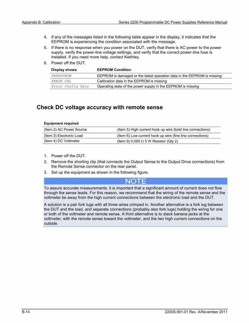
Appendix B: Calibration Series 2200 Programmable DC Power Supplies Reference Manual
B-14 2200S-901-01 Rev. A/November 2011
4. If any of the messages listed in the following table appear in the display, it indicates that the EEPROM is experiencing the condition associated with the message.
5. If there is no response when you power on the DUT, verify that there is AC power to the power supply, verify the power-line voltage settings, and verify that the correct power-line fuse is installed. If you need more help, contact Keithley.
6. Power off the DUT. Display shows EEPROM Condition ERREEPROM EEPROM is damaged or the latest operation data in the EEPROM is missing ERROR CAL Calibration data in the EEPROM is missing Error Config Data Operating state of the power supply in the EEPROM is missing
Check DC voltage accuracy with remote sense
Equipment required (Item 2) AC Power Source (Item 5) High current hook up wire (bold line connections)
(Item 3) Electronic Load (Item 6) Low current hook up wire (fine line connections) (Item 4) DC Voltmeter (Item 9) 0.050 5 W Resistor (Qty 2)
1. Power off the DUT. 2. Remove the shorting clip (that connects the Output Sense to the Output Drive connections) from
the Remote Sense connector on the rear panel. 3. Set up the equipment as shown in the following figure.
To assure accurate measurements, it is important that a significant amount of current does not flow through the sense leads. For this reason, we recommend that the wiring of the remote sense and the voltmeter be away from the high current connections between the electronic load and the DUT.
A solution is a pair fork lugs with all three wires crimped in. Another alternative is a fork lug between the DUT and the load, and separate connections (probably also fork lugs) holding the wiring for one or both of the voltmeter and remote sense. A third alternative is to stack banana jacks at the voltmeter, with the remote sense toward the voltmeter, and the two high current connections on the outside.

Series 2200 Programmable DC Power Supplies Reference Manual Appendix B: Calibration
2200S-901-01 Rev. A/November 2011 B-15
Figure 18: DC voltage accuracy with remote sense test setup

Appendix B: Calibration Series 2200 Programmable DC Power Supplies Reference Manual
B-16 2200S-901-01 Rev. A/November 2011
4. Power on the DUT.
Ensure the warm-up criteria has been met as described in the Performance Verification Conditions.
5. Set the voltmeter as follows: a. Set to measure DC volts. b. Set to auto range. c. Verify that the Math mX+b function is disabled (shift Dcv), assuring that volts are being read.
6. Set the electronic load as follows: a. Set to Constant Current. b. Set to draw a constant current at the test current specified for the DUT in the table DC voltage accuracy with remote sense (on page B-3).
7. Set the DUT to the full scale (FS) output current. 8. Set the DUT to 0% of the FS output voltage (0 V). 9. Turn the DUT output on. 10. Enter the voltmeter reading into the table DC voltage accuracy with remote sense (on page B-3). 11. Increase the DUT output voltage by 25% of the FS output voltage. 12. Repeat steps 10 and 11 until you complete testing at 100% of the FS. 13. Power off the DUT. 14. Disconnect the hook up wires from the Remote Sense connector and reinstall the shorting clip
between the Output Sense and Output Drive connectors as shown in the following figure.
Figure 19: Installing shorting clip on remote sense connector
15. Power on the DUT.
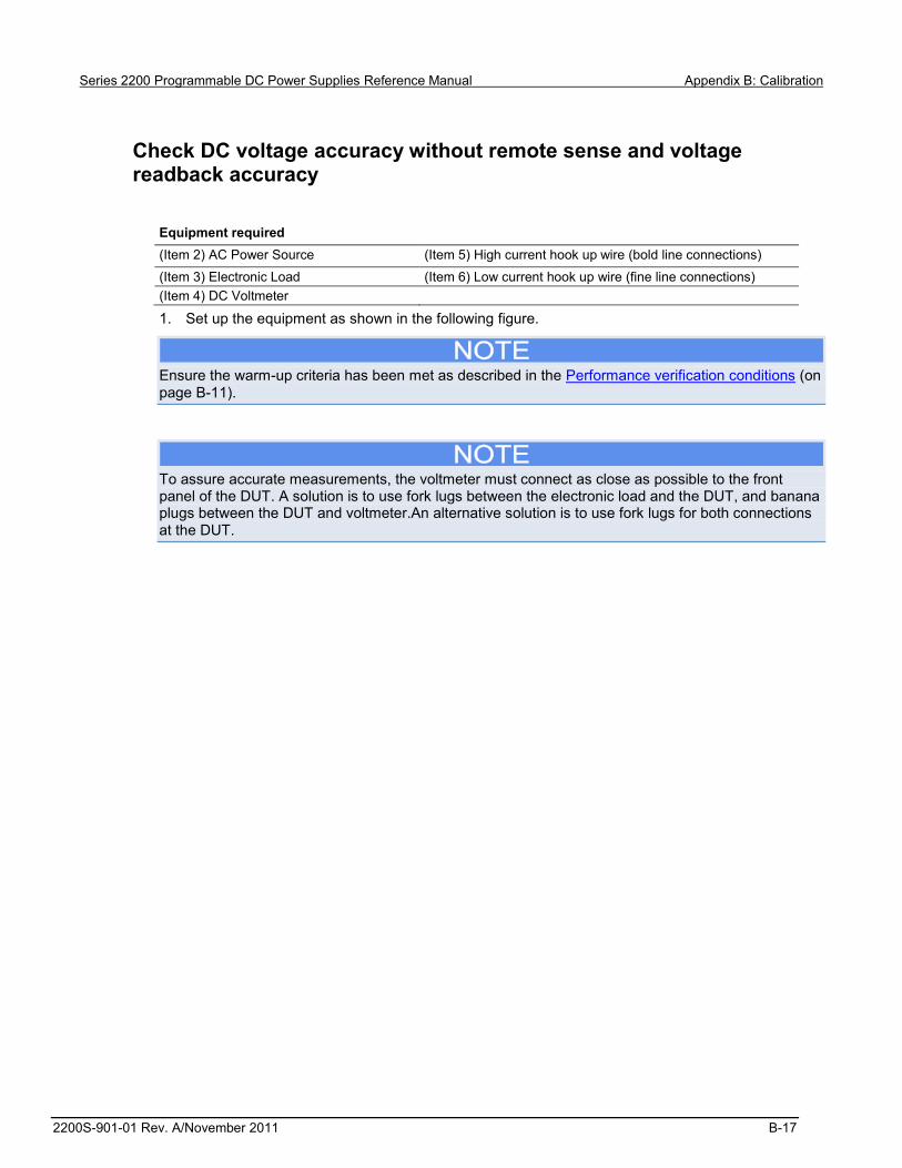
Series 2200 Programmable DC Power Supplies Reference Manual Appendix B: Calibration
2200S-901-01 Rev. A/November 2011 B-17
Check DC voltage accuracy without remote sense and voltage readback accuracy
Equipment required (Item 2) AC Power Source (Item 5) High current hook up wire (bold line connections)
(Item 3) Electronic Load (Item 6) Low current hook up wire (fine line connections) (Item 4) DC Voltmeter
1. Set up the equipment as shown in the following figure.
Ensure the warm-up criteria has been met as described in the Performance verification conditions (on page B-11).
To assure accurate measurements, the voltmeter must connect as close as possible to the front panel of the DUT. A solution is to use fork lugs between the electronic load and the DUT, and banana plugs between the DUT and voltmeter.An alternative solution is to use fork lugs for both connections at the DUT.

Appendix B: Calibration Series 2200 Programmable DC Power Supplies Reference Manual
B-18 2200S-901-01 Rev. A/November 2011
Figure 20: Voltage accuracy regulation and protection test setup
2. Set the voltmeter as follows:
a. Set to measure DC volts. b. Set to auto range. c. Verify that the Math mX+b function is disabled (shift Dcv), assuring that volts are being read.
3. Set the electronic load as follows: a. Set to Constant Current. b. Set to draw a constant current at the test current specified for the DUT in the table DC voltage accuracy without remote sense (on page B-4).
4. Set the DUT to the full scale (FS) output current. 5. Set the DUT to 0% of the FS output voltage (0 V). 6. Turn the DUT output on. 7. Enter the voltmeter reading into the table DC voltage accuracy without remote sense (on page B-
4). 8. Enter the voltmeter reading into the table DC voltage readback accuracy (on page B-5). 9. Enter the DUT Readback Voltage into the table DC voltage readback accuracy (on page B-5). 10. Calculate the difference of the two measurements taken in steps 8 and 9 and enter the absolute
value into the difference column of the table. DC voltage readback accuracy (on page B-5). 11. Increase the DUT output voltage by 25% of the FS output voltage. 12. Repeat steps 7 through 11 until you complete testing at 100% of FS.

Series 2200 Programmable DC Power Supplies Reference Manual Appendix B: Calibration
2200S-901-01 Rev. A/November 2011 B-19
Check DC voltage line regulation This check procedure uses the same test setup as the previous procedure. (see Check DC voltage accuracy without remote sense and voltage readback accuracy (on page B-17)).
1. Change the AC Power Source output to the minimum voltage specified in the following table. DUT voltage selector switch AC power source voltage 110 98 V 220 196 V
Ensure the warm-up criteria has been met as described in the Performance Verification Conditions.
2. Set the voltmeter as follows:
a. Set to measure DC volts. b. Set to auto range. c. Verify that the Math mX+b function is disabled (shift Dcv), assuring that volts are being read.
3. Set the electronic load as follows: a. Set to Constant Current. b. Set to draw the specified test current. Instrument Test current 2200 - 20 - 5 2.5 A 2200 - 30 - 5 2.5 A
2200 - 32 - 3 1.5 A 2200 - 60 - 2 1.25 A 2200 - 72 - 1 0.63 A
4. Set the DUT to 100% of the full scale (FS) output current. 5. Set the DUT to 100% of the FS output voltage. 6. Turn the DUT output on. 7. Enter the voltmeter reading into the table DC voltage line regulation (on page B-6) under the Min
column for your product. 8. Change the AC Power Source output to the maximum voltage specified in the following table.
DUT voltage selector switch AC power source voltage 110 132 V 220 264 V
9. Enter the voltmeter reading into the table DC voltage line regulation (on page B-6) under the Max
column for your product.
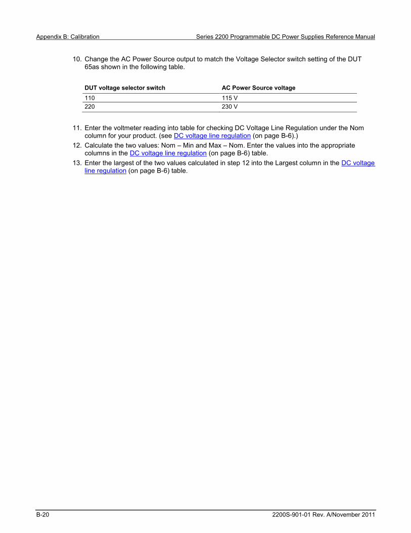
Appendix B: Calibration Series 2200 Programmable DC Power Supplies Reference Manual
B-20 2200S-901-01 Rev. A/November 2011
10. Change the AC Power Source output to match the Voltage Selector switch setting of the DUT 65as shown in the following table. DUT voltage selector switch AC Power Source voltage 110 115 V 220 230 V
11. Enter the voltmeter reading into table for checking DC Voltage Line Regulation under the Nom
column for your product. (see DC voltage line regulation (on page B-6).) 12. Calculate the two values: Nom – Min and Max – Nom. Enter the values into the appropriate
columns in the DC voltage line regulation (on page B-6) table. 13. Enter the largest of the two values calculated in step 12 into the Largest column in the DC voltage
line regulation (on page B-6) table.

Series 2200 Programmable DC Power Supplies Reference Manual Appendix B: Calibration
2200S-901-01 Rev. A/November 2011 B-21
Check DC voltage load regulation This check procedure uses the same test setup as the previous procedure. (see Check DC voltage accuracy without remote sense and voltage readback accuracy (on page B-17))
Ensure the warm-up criteria has been met as described in the Performance Verification Conditions.
1. Set the voltmeter as follows:
a. Set to measure DC volts. b. Set to auto range. Verify that the Math mX+b function is disabled (shift Dcv), assuring that volts are being read.
2. Set the electronic load as follows: a. Set to Constant Current. b. Set to draw 0 Amps.
3. Set the DUT to 100% of the full scale (FS) output current. 4. Set the DUT to 100% of the FS output voltage. 5. Turn the DUT output on. 6. Enter the voltmeter reading into the table DC voltage load regulation (on page B-6) under the Min
column for your product. 7. Increase the electronic load to the reference load test current value.
Instrument Test current 2200- 20 - 5 2.5 A 2200 - 30 - 5 2.5 A
2200 - 32 - 3 1.5 A 2200 - 60 - 2 1.25 A 2200 - 72 - 1 0.6 A
8. Enter the voltmeter reading into the table DC voltage load regulation (on page B-6) under the
reference load column for your product. 9. Increase the electronic load to the maximum load test current value.
Instrument Test current 2200- 20 - 5 4.9 A 2200 - 30 - 5 4.9 A
2200 - 32 - 3 2.94 A 2200 - 60 - 2 2.45 A 2200 - 72 - 1 1.17 A
10. Enter the voltmeter reading into table for checking DC Voltage Load Regulation under the Nom
column for your product. (see DC voltage load regulation (on page B-6).) 11. Calculate the three values: Ref – Min, Max – Ref, and (Max – Ref)/0.98. Enter the values into the
appropriate columns in the DC voltage load regulation (on page B-6) table.

Appendix B: Calibration Series 2200 Programmable DC Power Supplies Reference Manual
B-22 2200S-901-01 Rev. A/November 2011
12. Enter the largest of the three values calculated in step 11 into the Largest column in the DC voltage load regulation (on page B-6) table.

Series 2200 Programmable DC Power Supplies Reference Manual Appendix B: Calibration
2200S-901-01 Rev. A/November 2011 B-23
Check DC overvoltage detection This check procedure uses the same test setup as the previous procedure. (see Check DC voltage accuracy without remote sense and voltage readback accuracy (on page B-17))
Ensure the warm-up criteria has been met as described in the Performance Verification Conditions.
1. Set the voltmeter as follows:
a. Set to measure DC volts. b. Set to auto range. c. Verify that the Math mX+b function is disabled (shift Dcv), assuring that volts are being read.
2. Set the electronic load as follows: a. Set to Constant Current. b. Set to draw 1 Amp.
3. Set the DUT to 100% of the full scale (FS) output current. 4. Set the DUT to 4 V output voltage.
OVP and Max Volt Set are submenus of the Protect menu.
5. Set the DUT OVP (Over Voltage Protection) to ON, set the OVP threshold to 5 V, and turn Max
Volt off as follows: a. Press Shift and Menu (1). b. Press the down arrow until Protect is shown and press Enter. c. Press the down arrow until OVP Set is shown and press Enter. d. Press the down arrow until On is shown and press Enter. e. Press 5 and press Enter. f. Press the down arrow until Max Volt Set is shown and press Enter. g. Press the down arrow until Off is shown and press Enter. h. Press the Esc key as needed to exit the menu system.
6. Turn the DUT output on.
During the next step, closely monitor the voltmeter reading. Noting the highest output voltage achieved before OVP is triggered.
7. Slowly increase the DUT output voltage until OVP is triggered. When triggered, the output voltage
abruptly drops below 1 V, signals with beeps, and OVP is indicated in the display.

Appendix B: Calibration Series 2200 Programmable DC Power Supplies Reference Manual
B-24 2200S-901-01 Rev. A/November 2011
8. Enter the voltmeter reading (where OVP triggering occurred) into the DC overvoltage detection (on page B-6) table for checking DC Overvoltage Detection.
9. Reset OVP. a. Press Shift and Menu (1). b. Press the down arrow until Protect is shown and press Enter. c. Press the down arrow until Reset Protect is shown and press Enter. d. Press the right arrow to select Yes and press Enter. e. Press the Esc key as needed to exit the menu system.

Series 2200 Programmable DC Power Supplies Reference Manual Appendix B: Calibration
2200S-901-01 Rev. A/November 2011 B-25
Check DC current and DC current readback accuracy
Equipment required (Item 2) AC Power Source (Item 5) High current hook up wire (bold line connections)
(Item 3) Electronic Load (Item 7) High Accuracy 0.05 Ω Resistor (Item 4) DC Voltmeter (Item 8) Current Shunt Resistor Cabling
1. Set up the equipment as shown in the following figure.
Ensure the warm-up criteria has been met as described in the Performance verification conditions (on page B-11).
Figure 21: DC current accuracy and regulation test setup

Appendix B: Calibration Series 2200 Programmable DC Power Supplies Reference Manual
B-26 2200S-901-01 Rev. A/November 2011
2. Set the voltmeter as follows:
a. Set to measure DC volts. b. Set to auto range. c. Set to show amps (instead of volts) by multiplying the voltmeter result by 20.
Press Shift DC V (mX+B) Use the arrow key to move the cursor as far to the right as it can go until it is positioned on the ^. Press the up range button once: M=10.00000 Move the arrow key to the 1's digit and up range once: M=20.00000 Press Enter. The display shows B=0 Press Enter. The display shows Units: Use the arrow keys to modify the display to show AMP. Adjust each letter individually.
3. Set the electronic load as follows:
a. Set to Constant Voltage. b. Set to the specified voltage for your DUT (see DC current accuracy (on page B-7)).
4. Set the DUT to 0% of the full scale (FS) output current. 5. Set the DUT to 100% of the FS output voltage. 6. Turn the DUT output on. 7. Enter the voltmeter reading into the table DC current accuracy (on page B-7). 8. Enter the voltmeter reading into the table DC current readback accuracy (on page B-8). 9. Enter the DUT current readout into the table DC current readback accuracy (on page B-8) under
the current readout column. 10. Calculate the difference of the two measurements taken in steps 8 and 9. Enter the absolute
value of the calculated value into the difference column of the table. DC current readback accuracy (on page B-8).
11. Increase the DUT output current by 25% of the FS output current. 12. Repeat steps 7 through 11 until you complete testing at 100% of the FS output current.
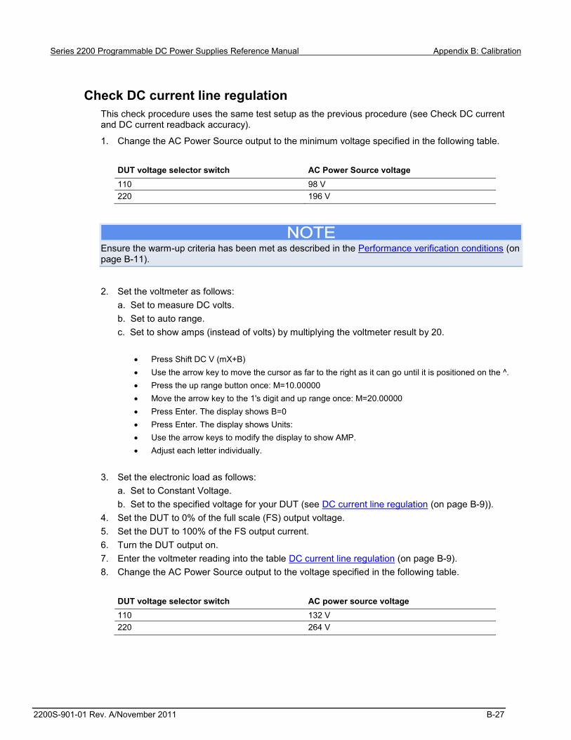
Series 2200 Programmable DC Power Supplies Reference Manual Appendix B: Calibration
2200S-901-01 Rev. A/November 2011 B-27
Check DC current line regulation This check procedure uses the same test setup as the previous procedure (see Check DC current and DC current readback accuracy).
1. Change the AC Power Source output to the minimum voltage specified in the following table. DUT voltage selector switch AC Power Source voltage 110 98 V 220 196 V
Ensure the warm-up criteria has been met as described in the Performance verification conditions (on page B-11).
2. Set the voltmeter as follows:
a. Set to measure DC volts. b. Set to auto range. c. Set to show amps (instead of volts) by multiplying the voltmeter result by 20.
Press Shift DC V (mX+B) Use the arrow key to move the cursor as far to the right as it can go until it is positioned on the ^. Press the up range button once: M=10.00000 Move the arrow key to the 1's digit and up range once: M=20.00000 Press Enter. The display shows B=0 Press Enter. The display shows Units: Use the arrow keys to modify the display to show AMP. Adjust each letter individually.
3. Set the electronic load as follows:
a. Set to Constant Voltage. b. Set to the specified voltage for your DUT (see DC current line regulation (on page B-9)).
4. Set the DUT to 0% of the full scale (FS) output voltage. 5. Set the DUT to 100% of the FS output current. 6. Turn the DUT output on. 7. Enter the voltmeter reading into the table DC current line regulation (on page B-9). 8. Change the AC Power Source output to the voltage specified in the following table.
DUT voltage selector switch AC power source voltage 110 132 V 220 264 V

Appendix B: Calibration Series 2200 Programmable DC Power Supplies Reference Manual
B-28 2200S-901-01 Rev. A/November 2011
9. Enter the voltmeter reading into the Max line for your product.in the table DC current line regulation (on page B-9).
10. Change the AC Power Source output to the voltage specified in the following table. DUT voltage selector switch AC power source voltage 110 115 V 220 230 V
11. Enter the voltmeter reading into the Nom line for your product in the table DC current line
regulation (on page B-9). 12. Calculate the two values: Nom – Min and Max – Nom. Enter the values into the appropriate
columns in the DC current line regulation (on page B-9) table. 13. Select the largest of the two calculations from step 12 and enter the value into the Largest column
in the DC current line regulation (on page B-9) table. 14. Turn the DUT output off.

Series 2200 Programmable DC Power Supplies Reference Manual Appendix B: Calibration
2200S-901-01 Rev. A/November 2011 B-29
Check DC current load regulation This check procedure uses the same test setup as the previous procedure (see Check DC current line regulation (on page B-27)).
1. Set the voltmeter as follows: a. Set to measure DC volts. b. Set to auto range. c. Set to show amps (instead of volts) by multiplying the voltmeter result by 20.
Press Shift DC V (mX+B) Use the arrow key to move the cursor as far to the right as it can go until it is positioned on the ^. Press the up range button once: M=10.00000 Move the arrow key to the 1's digit and up range once: M=20.00000 Press Enter. The display shows B=0 Press Enter. The display shows Units: Use the arrow keys to modify the display to show AMP. Adjust each letter individually.
2. Set the electronic load as follows:
a. Set to Constant Voltage. b. Set to the minimum test voltage level. Instrument Minimum test voltage 2200 - 20 - 5 2.0 V 2200 - 30 - 5 3.0 V
2200 - 32 - 3 3.2 V 2200 - 60 - 2 6.0 V 2200 - 72 - 1 7.2 V
3. Set the DUT to 100% of the FS output current for your product. 4. Set the DUT to 100% of the FS output voltage for your product. 5. Turn the DUT output on. 6. Enter the voltmeter reading into the DC current load regulation table for checking current load
regulation at the minimum voltage for your product. 7. Increase the electronic load to the Reference test voltage level.
Instrument Minimum test voltage 2200 - 20 - 5 10.0 V 2200 - 30 - 5 15.0 V
2200 - 32 - 3 16.0 V 2200 - 60 - 2 30.0 V 2200 - 72 - 1 36.0 V

Appendix B: Calibration Series 2200 Programmable DC Power Supplies Reference Manual
B-30 2200S-901-01 Rev. A/November 2011
8. Enter the voltmeter reading into the DC current load regulation table for checking current load regulation at the reference test voltage for your product.
9. Increase the electronic load to the Maximum test voltage level. Instrument Minimum test voltage 2200 - 20 - 5 18.0 V 2200 - 30 - 5 27.0 V
2200 - 32 - 3 28.8 V 2200 - 60 - 2 54.0 V 2200 - 72 - 1 64.8 V
10. Enter the voltmeter reading into the DC current load regulation table for checking current load
regulation at the maximum voltage for your product. 11. Calculate the two values: REF – Min and Max – REF. Enter the values into the appropriate
columns in the DC current load regulation table. 12. Power off the DUT and test equipment.

Series 2200 Programmable DC Power Supplies Reference Manual Appendix B: Calibration
2200S-901-01 Rev. A/November 2011 B-31
Check voltage noise (7 MHz)
Equipment required (Item 5) High current hook up wire (bold line connections)
(Item 12) Oscilloscope
(Item 10) Load Resistor (Item 13) Oscilloscope 1X probe
1. Plug the DUT into your local line power from the mains. 2. Plug the test oscilloscope into the same mains outlet as the DUT.
Some AC Power Sources create large amounts of high frequency noise on the power line that the instrument may not fully reject. Noise directly on the mains is typically better controlled.
Use the same mains outlet for both the DUT and test oscilloscope to avoid ground loops which may cause noise.
3. Power on the DUT and test oscilloscope.
Ensure the warm-up criteria has been met as described in the Performance verification conditions (on page B-11).
4. Set up the equipment as shown in the following figure.
Use the appropriate load resistor depending on the model of the DUT. See Voltage noise at 7 MHz (on page B-10) for information.
Figure 22: 7 MHz test setup

Appendix B: Calibration Series 2200 Programmable DC Power Supplies Reference Manual
B-32 2200S-901-01 Rev. A/November 2011
5. Set the oscilloscope as follows:
a. 1 mV/division b. 1 M input resistance c. 20 MHz bandwidth (BW) limit d. AC Coupled e. Auto-trigger f. 1 ms/div g. Set to measure Vp-p and VRMS
6. Set the oscilloscope probe to 1X mode. 7. Set the DUT to the 100% FS output voltage. 8. Set the DUT to the 100% FS output current. 9. Turn the DUT output on.
Do not touch the load resistor. The load resistor may become hot enough to cause burns.
10. Enter the oscilloscope measurements into the Voltage noise at 7 MHz (on page B-10) table for
checking Noise at 7 MHz.

Series 2200 Programmable DC Power Supplies Reference Manual Appendix B: Calibration
2200S-901-01 Rev. A/November 2011 B-33
Check voltage noise (20 MHz)
Equipment required (Item 5) High current hook up wire (bold line connections)
(Item 15) Coaxial cable (BNC M-M)
(Item 10) Load Resistor (Item 16) BNC F-to-Banana (Item 12) Oscilloscope
1. Plug the DUT into your local line power from the mains. 2. Plug the test oscilloscope into the same mains outlet as the DUT.
Some AC Power Sources create large amounts of high frequency noise on the power line that the instrument may not fully reject. Noise directly on the mains is typically better controlled.
Use the same mains outlet for both the DUT and test oscilloscope to avoid ground loops which may cause noise.
3. Power on the DUT and test oscilloscope.
Ensure the warm-up criteria has been met as described in the Performance Verification Conditions.
4. Set up the equipment as shown in the following figure. Use the appropriate load resistor depending on the model of the DUT. See Voltage noise at 20 MHz (on page B-10) for information.

Appendix B: Calibration Series 2200 Programmable DC Power Supplies Reference Manual
B-34 2200S-901-01 Rev. A/November 2011
Figure 23: 20 MHz voltage noise test setup
5. Set the oscilloscope as follows: a. 1 mV/division b. 1 M input resistance c. 20 MHz bandwidth (BW) limit d. AC Coupled e. Auto-trigger f. 1 ms/div g. Set to measure Vp-p and VRMS
6. Set the DUT to the 100% FS output voltage. 7. Set the DUT to the 100% FS output current. 8. Turn the DUT output on.
Do not touch the load resistor. The load resistor may become hot enough to cause burns.
9. Enter the oscilloscope measurements into the Voltage noise at 20 MHz (on page B-10) table for
checking Noise at 20 MHz.

Series 2200 Programmable DC Power Supplies Reference Manual Appendix B: Calibration
2200S-901-01 Rev. A/November 2011 B-35
Check current noise
Equipment required (Item 5) High current hook up wire (bold line connections)
(Item 12) Oscilloscope
(Item 11) 1 Load Resistor (Item 14) Oscilloscope 10X probe
1. Plug the DUT into your local line power from the mains. 2. Plug the test oscilloscope into the same mains outlet as the DUT.
Some AC Power Sources create large amounts of high frequency noise on the power line that the instrument may not fully reject. Noise directly on the mains is typically better controlled.
Use the same mains outlet for both the DUT and test oscilloscope to avoid ground loops which may cause noise.
3. Power on the DUT and test oscilloscope.
Ensure the warm-up criteria has been met as described in the Performance Verification Conditions.
4. Set up the equipment as shown in the following figure. Use the appropriate load resistor depending on the model of the DUT. See Voltage noise at 20 MHz (on page B-10) for information.
Figure 24: 20 MHz current noise test setup

Appendix B: Calibration Series 2200 Programmable DC Power Supplies Reference Manual
B-36 2200S-901-01 Rev. A/November 2011
5. Set the oscilloscope as follows: a. 1 mV/division b. 1 M input resistance c. 20 MHz bandwidth (BW) limit d. AC Coupled e. Auto-trigger f. 1 ms/div g. Set to measure Vp-p and VRMS
6. Set the DUT to the 100% FS output voltage. 7. Set the DUT to the 100% FS output current. 8. Turn the DUT output on.
Do not touch the load resistor. The load resistor may become hot enough to cause burns.
9. Enter the oscilloscope measurements into the Current noise at 20 MHz (on page B-10) table for
checking current noise. 10. Power off the DUT and test equipment.
This completes the performance verification procedure.

Series 2200 Programmable DC Power Supplies Reference Manual Appendix B: Calibration
2200S-901-01 Rev. A/November 2011 B-37


In this appendix:
Status and events .................................................................... C-1 Status reporting structure ........................................................ C-1 Registers ................................................................................. C-3
Status and events This appendix provides details about the status information and events the power supply reports.
Status reporting structure A diagram is provided showing an outline of the power supply error and event reporting function.
The error and event reporting system consists of the following three blocks:
Standard/Event Status Operation Status Questionable Status
The operations processed in these blocks are summarized in status bytes, which provide the error and event data.
Appendix C
Status model

Appendix C: Status model Series 2200 Programmable DC Power Supplies Reference Manual
C-2 2200S-901-01 Rev. A/November 2011
Figure 25: Error and event handling process

Series 2200 Programmable DC Power Supplies Reference Manual Appendix C: Status model
2200S-901-01 Rev. A/November 2011 C-3
Registers The registers in the event reporting system fall into two functional groups:
Status registers contain information about the status of the power supply. They include the standard event status register (SESR).
Enable registers determine whether selected types of events are reported to the status registers and the event queue. They include the event status enable register (ESER), the service request enable register (SRER), the operation enable register (OENR), and the questionable enable register (QENR).
Status registers This topic describes the following six types of status registers:
Status byte register (SBR) (on page C-3) Standard event status register (SESR) (on page C-4) Operation condition register (OCR) (on page C-5) Operation event register (OEVR) (on page C-5) Questionable condition register (QCR) (on page C-5) Questionable event register (QEVR) (on page C-6)
The questionable event register may be filtered by a positive transition filter (Questionable positive transition register (QPTR) (on page C-6)) and a negative transition filter (Questionable negative transition register (QNTR) (on page C-6)).
Status byte register (SBR) The status byte register is made up of 8 bits. Bits 4, 5 and 6 are defined in accordance with IEEE Std 488.2-1992. These bits are used to monitor the output queue, standard event status register, and service requests, respectively.
Figure 26: Status byte register (SBR)
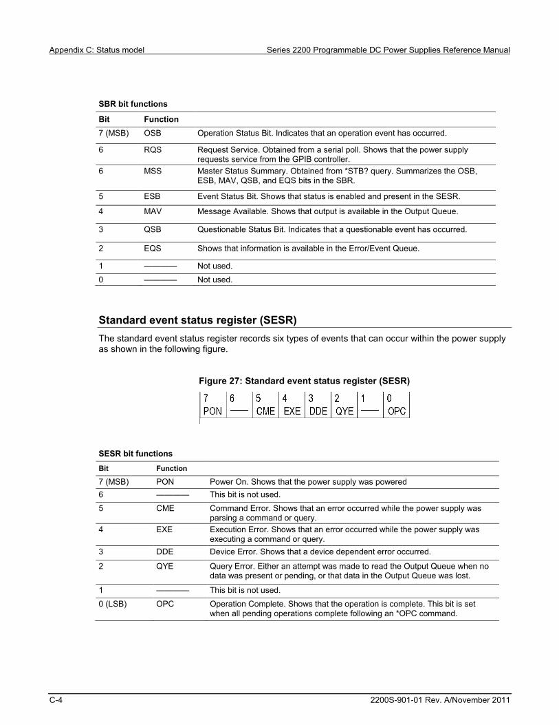
Appendix C: Status model Series 2200 Programmable DC Power Supplies Reference Manual
C-4 2200S-901-01 Rev. A/November 2011
SBR bit functions
Bit Function 7 (MSB) OSB Operation Status Bit. Indicates that an operation event has occurred.
6 RQS Request Service. Obtained from a serial poll. Shows that the power supply requests service from the GPIB controller.
6 MSS Master Status Summary. Obtained from *STB? query. Summarizes the OSB, ESB, MAV, QSB, and EQS bits in the SBR.
5 ESB Event Status Bit. Shows that status is enabled and present in the SESR.
4 MAV Message Available. Shows that output is available in the Output Queue.
3 QSB Questionable Status Bit. Indicates that a questionable event has occurred.
2 EQS Shows that information is available in the Error/Event Queue.
1 ———— Not used.
0 ———— Not used.
Standard event status register (SESR) The standard event status register records six types of events that can occur within the power supply as shown in the following figure.
Figure 27: Standard event status register (SESR)
SESR bit functions
Bit Function
7 (MSB) PON Power On. Shows that the power supply was powered 6 ———— This bit is not used.
5 CME Command Error. Shows that an error occurred while the power supply was parsing a command or query.
4 EXE Execution Error. Shows that an error occurred while the power supply was executing a command or query.
3 DDE Device Error. Shows that a device dependent error occurred.
2 QYE Query Error. Either an attempt was made to read the Output Queue when no data was present or pending, or that data in the Output Queue was lost.
1 ———— This bit is not used.
0 (LSB) OPC Operation Complete. Shows that the operation is complete. This bit is set when all pending operations complete following an *OPC command.

Series 2200 Programmable DC Power Supplies Reference Manual Appendix C: Status model
2200S-901-01 Rev. A/November 2011 C-5
Operation condition register (OCR) The operation condition register is made up of eight bits, which note the occurrence of events as shown here.
Figure 28: Operation Condition Register (OCR)
OCR bit functions
Bit Function
7 (MSB) ———— This bit is not used. 6 ———— This bit is not used.
5 RUN Running List. Indicates that the power supply is executing a lis 4 TBF Trace Buffer Full. This bit is used internally, by the instrument. 3 CC Constant Current. Indicates that the power supply is in constant current mode
and is regulating its output current. 2 CV Constant Voltage. Indicates that the power supply is in constant voltage mode
and is regulating its output voltage.
1 WTG Waiting for Trigger. Indicates that the power supply is waiting for a trigger
0 (LSB) CAL Calibrating. Indicates that the power supply is calculating a new calibration parameter.
Operation event register (OEVR) The operation event register has the same content as the operation condition register. See Operation condition register (OCR) (on page C-5) for information on the operation event register.
Questionable condition register (QCR) The questionable condition register is made up of eight bits which note the occurrence of five types of events as shown in the following figure.
Figure 29: Questionable condition register (QCR)

Appendix C: Status model Series 2200 Programmable DC Power Supplies Reference Manual
C-6 2200S-901-01 Rev. A/November 2011
SESR bit functions
Bit Function
7 (MSB) ———— This bit is not used. 6 ———— This bit is not used.
5 ———— This bit is not used. 4 PS Protection Shutdown. 3 RI Remote Inhibit. This bit indicates the state of the Remote Inhibit input.
2 UNR Unregulated. Indicates that the power supply has gone out of regulation.
1 OT Over Temperature. Indicates that the power supply has experienced an over temperature condition and the output has been shut down.
0 (LSB) OV Over Voltage. Indicates that the overvoltage protection threshold has been exceeded and the output has shut down.
Questionable positive transition register (QPTR) The Questionable event register (QEVR) (on page C-6) can be configured to respond to specific transitions in the Questionable condition register (QCR) (on page C-5). The transitions and the polarity of these transitions are specified in the qestionable positive transition register (QPTR) and Questionable negative transition register (QNTR) (on page C-6). These registers act as filters between the QCR and the QEVR. If a bit is set to 1 in the QNTR, the corresponding bit in the QEVR will be set to 1 whenever the same bit in the QCR makes a negative transition, from 1 to 0. If a bit is set to 1 in the QPTR, the corresponding bit in the QEVR will be set to 1 when the same bit in the QCR makes a positive transition, from 0 to 1.
Questionable negative transition register (QNTR) The Questionable event register (QEVR) (on page C-6) can be configured to respond to specific transitions in the Questionable condition register (QCR) (on page C-5). The transitions and the polarity of these transitions are specified in the Questionable positive transition register (QPTR) (on page C-6) and Questionable negative transition register (QNTR). These registers act as filters between the QCR and the QEVR. If a bit is set to 1 in the QNTR, the corresponding bit in the QEVR will be set to 1 whenever the same bit in the QCR makes a negative transition, from 1 to 0. If a bit is set to 1 in the Questionable positive transition register (QPTR), the corresponding bit in the QEVR will be set to 1 when the same bit in the QCR makes a positive transition, from 0 to 1.
Questionable event register (QEVR) The questionable event register is made up of eight bits, which have the same significance as the Questionable condition register (QCR) (on page C-5), but have been filtered by the Questionable positive transition register (QPTR) (on page C-6) and Questionable negative transition register (QNTR) (on page C-6).

Series 2200 Programmable DC Power Supplies Reference Manual Appendix C: Status model
2200S-901-01 Rev. A/November 2011 C-7
Enable registers This topic describes the following four types of enable registers:
Event status enable register (ESER) (on page C-7) Service request enable register (SRER) (on page C-7) Operation enable register (OENR) (on page C-8) Questionable enable register (QENR) (on page C-8)
ESER, SRER, OENR, and QENR allow you to select which events are reported to the status byte register (SBR). Each bit in an enable register corresponds to a bit in an event register. In order for an event to be reported to a bit in the status byte register (SBR), the corresponding bit in the enable register must be set to one. If the bit in the enable register is set to zero, the event will not affect the status bit. Various commands set the bits in the enable registers. The enable registers and the commands used to set them are described in the following topics.
Event status enable register (ESER) This register controls which types of events are summarized by the event status bit (ESB) in the status byte register (SBR). Use the *ESE command to set the bits in the ESER. Use the *ESE? query to read it.
Figure 30: Event status enable register (ESER)
Service request enable register (SRER) This register controls which bits in the status byte register (SBR) generate a Service Request and are summarized by the master status summary (MSS) bit.
Use the *SRE command to set the SRER. Use the *SRE? query to read the register. The RQS bit remains set to one until either the SBR is read with a Serial Poll or the MSS bit changes back to a zero.
Figure 31: Service request enable register (SRER)

Appendix C: Status model Series 2200 Programmable DC Power Supplies Reference Manual
C-8 2200S-901-01 Rev. A/November 2011
Operation enable register (OENR) The OENR consists of bits defined exactly the same as bits 0 through 7 in the OEVR. You can use this register to control whether or not the operation status bit (OSB) in the SBR is set when an event occurs and the corresponding OEVR bit is set.
Use the STATus:OPERation:ENABle command to set the bits in the OENR.
Use the STATus:OPERation:ENABle? query to read the contents of the OENR.
Figure 32: Operation enable register (OENR)
Questionable enable register (QENR) The QENR consists of bits defined exactly the same as bits 0 through 7 in the QEVR register. You can use this register to control whether the QSB in the SBR is set when an event occurs and the corresponding QEVR bit is set.
Use the STATus:QUEStionable:ENABle command to set the bits in the QENR.
Use the STATus:QUEStionable:ENABle? query to read the contents of the QENR.
Figure 33: Questionable enable register (QENR)
*PSC Command The *PSC command controls the enable registers contents at power-on. Sending *PSC 1 sets the enable registers at power on as follows:
ESER 0 (equivalent to an *ESE 0 command) SRER 0 (equivalent to an *SRE 0 command)
Sending *PSC 0 lets the enable registers maintain their values in nonvolatile memory through a power cycle.
Queues Output queue The power supply stores query responses in the Output Queue and empties this queue each time it receives a new command or query message after an <EOM>. The controller must read a query response before it sends the next command (or query) or it will lose responses to earlier queries.

Series 2200 Programmable DC Power Supplies Reference Manual Appendix C: Status model
2200S-901-01 Rev. A/November 2011 C-9
Error/event queue The Event Queue stores detailed information on up to 32 events. When 32 events stack up in the Event Queue, the 32nd event is replaced by event code 350, "Queue Overflow."
Read the Event Queue with the EVENT? query (which returns only the event number), with the EVMSG? query (which returns the event number and a text description of the event), or with the ALLEV? query (which returns all the event numbers with a description of the event). Reading an event removes it from the queue.
Before reading an event from the Event Queue, you must use the *ESR? query to read the summary of the event from the SESR. This makes the events summarized by the *ESR? read available to the EVENT? and EVMSG? queries, and empties the SESR.
Reading the SESR erases any events that were summarized by previous *ESR? reads but not read from the Event Queue. Events that follow an *ESR? read are put in the Event Queue but are not available until *ESR? is used again.
Messages and codes Error and event codes with negative values are SCPI standard codes. Error and event codes with positive values are unique to the Series 2200.
No event messages
Code Message
0 No events to report; queue empty 1 No events to report; new events pending *ESR?

Appendix C: Status model Series 2200 Programmable DC Power Supplies Reference Manual
C-10 2200S-901-01 Rev. A/November 2011
Command errors The following table shows the command error messages generated by improper syntax. Check that the command is properly formed and that it follows the rules in the section on command Syntax.
Command error messages (CME bit 5)
Code Message
101 Design error: Too many numeric suffices in Command Spec 110 No Input Command to parse 114 Numeric suffix is invalid value 116 Invalid value in numeric or channel list, e.g. out of range 117 Invalid number of dimensions in a channel list 120 Parameter of type Numeric Value overflowed its storage 130 Wrong units for parameter 140 Wrong type of parameter(s) 150 Wrong number of parameters 160 Unmatched quotation mark in parameters (single/double) 165 Unmatched bracket 170 Command keywords were not recognized 180 No entry in list to retrieve 190 Too many dimensions in entry to be returned in parameters 191 Too many char
Execution errors
The following table lists the execution errors that are detected during execution of a command.
Execution error messages (EXE bit 4)
Code Message
-220 Execution error -221 Settings conflict -222 Data out of range -223 Too much data -224 Illegal parameter value -225 Out of memory –270 Macro error –272 Macro execution error –273 Illegal macro label –276 Macro recursion error –277 Macro redefinition not allowed

Series 2200 Programmable DC Power Supplies Reference Manual Appendix C: Status model
2200S-901-01 Rev. A/November 2011 C-11
System errors
The following table lists the system errors that can occur during power supply operation.
System error messages (DDE bit 3)
Code Message
–310 System error –350 Too many errors
Query errors
Query error messages (Standard Event Status Register bit 2)
Code Message
–400 Query error –410 Query INTERRUPTED –420 Query UNTERMINATED –430 Query DEADLOCKED –440 Query UNTERMINATED
Self test errors
The following table lists the self test errors that can occur during power supply operation.
Self test error messages (Standard Event Status Register bit 3)
Code Message
0 No error 1 Module Initialization Lost 2 Mainframe Initialization Lost 3 Module Calibration Lost 4 Non-volatile RAM STATE section checksum failed 5 Non-volatile RAM RST section checksum failed 10 RAM selftest 40 Flash write failed 41 Flash erase failed 80 Digital I/O selftest error
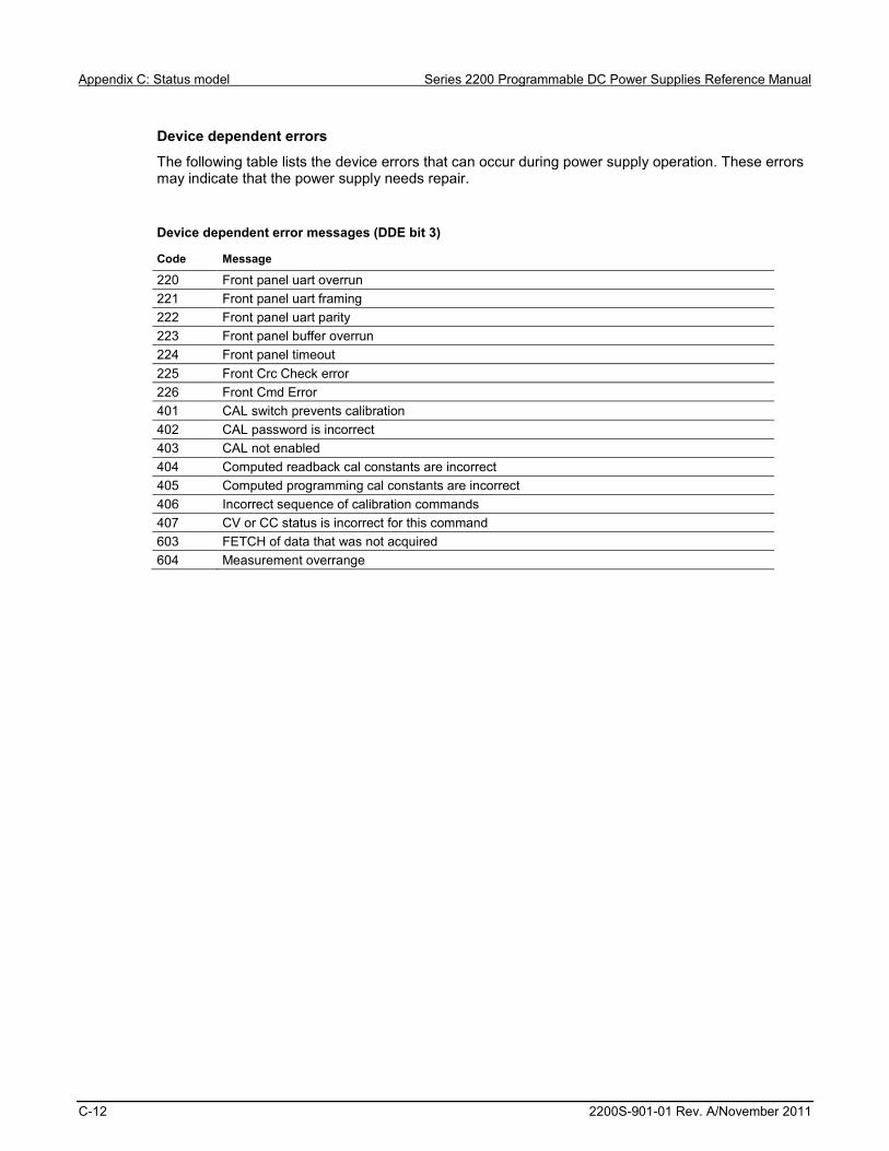
Appendix C: Status model Series 2200 Programmable DC Power Supplies Reference Manual
C-12 2200S-901-01 Rev. A/November 2011
Device dependent errors
The following table lists the device errors that can occur during power supply operation. These errors may indicate that the power supply needs repair.
Device dependent error messages (DDE bit 3)
Code Message
220 Front panel uart overrun 221 Front panel uart framing 222 Front panel uart parity 223 Front panel buffer overrun 224 Front panel timeout 225 Front Crc Check error 226 Front Cmd Error 401 CAL switch prevents calibration 402 CAL password is incorrect 403 CAL not enabled 404 Computed readback cal constants are incorrect 405 Computed programming cal constants are incorrect 406 Incorrect sequence of calibration commands 407 CV or CC status is incorrect for this command 603 FETCH of data that was not acquired 604 Measurement overrange
In this appendix:
ASCII code chart ..................................................................... D-2
Appendix D
Display character codes

Appendix D: Display character codes Series 2200 Programmable DC Power Supplies Reference Manual
D-2 2200S-901-01 Rev. A/November 2011
ASCII code chart Figure 34: ASCII code chart

A
Abbreviating commands, queries, and parameters • 3-7
Accessories • 1-2 optional • 1-3 standard • 1-2
Arrow keys • 2-6
B
BNF notation • 3-3
C
Calibration • B-1 CC message • 2-12 Chaining commands and queries • 3-8 Cleaning • A-1 Command and query structure • 3-4 Commands
Abbreviating • 3-7 Alphabetical order • 4-2 BNF notation • 3-3 Chaining • 3-8 Entry • 3-5 Errors • C-10 Functional groups • 3-9 Message terminators • 3-6 Parameter types • 3-7 Programming examples • 4-42 Queries • 3-5 SCPI commands and queries • 3-6 Syntax • 3-3
Configuration Default configuration • 2-17 Menu • 2-9 Timing • 3-2
Connectivity GPIB • 2-26, 3-2 USB • 2-28, 3-1
Current Current output check • 2-4 Setting the current limit • 2-17
CV message • 2-12
D
Display • 2-5
E
Esc key • 2-7
F
Factory reset • 2-8 Features • 1-2 Firmware version • 2-8 Front panel
Front panel at a glance • 2-5 Front panel operation • 2-15
Fuse • 1-4 Replace fuse • 5-1
G
GPIB connector • 2-14
I Installation • 2-3 Internal temperature • 2-8 I-set key • 2-6, 2-7
K
Keys Arrow • 2-6 Esc • 2-7 Key sound • 2-21 Numeric keypad • 2-6 Save and recall • 2-6 Shift • 2-7 Shift + numeric keypad descriptions • 2-7 V-Set, I-Set, Shift, and Output On/Off • 2-6
L
List Define • 2-24 Example of list • 2-31, 4-45 Run • 2-26
M
Message terminators • 3-6 Messages • 2-12
Index
Index Series 2200 Programmable DC Power Supplies Reference Manual
Index-2 2200S-901-01 Rev. A/November 2011
N
Navigation wheel • 2-6 Lock the navigation wheel • 2-22
Numeric keypad • 2-6 Special operations • 2-8 Unlock • 2-8
O
On/Off key • 2-6, 2-7 Optional accessories • 1-3
P
Parameter types • 3-7 Performance verification
Messages and codes • C-9 Overview • B-1 Procedures • B-11
Power Connector • 2-14 On and off • 2-3 Switch • 2-6 Voltage selector switch • 2-15
Q
Queries • 3-5 Query responses • 3-5
Queues Error/event queue • C-9 Output queue • C-8
R
Recall key • 2-7 Registers • C-3
Enable registers • C-7 *PSC Command • C-8 Event status enable register (ESER) • C-7 Operation enable register (OENR) • C-8 Questionable enable register (QENR) • C-8 Service request enable register (SRER) • C-7
Status registers • C-3 Operation condition register (OCR) • C-5 Operation event register (OEVR) • C-5 Questionable condition register (QCR) • C-6 Questionable positive transition register (QPTR) • C-6 Standard event status register (SESR) • C-4 Status byte register (SBR) • C-3
S
Save • 2-7 Save and recall keys • 2-6 SCPI commands • 3-8 SCPI commands and queries • 3-6 Shift + numeric keypad descriptions • 2-7
Shift key • 2-6, 2-7 Standard accessories • 1-2 Status and events • C-1
T
Troubleshooting • 5-1
V
Voltage configuration settings Define a list of voltage and current steps • 2-24 Setting the maximum voltage • 2-18 Setting the over-voltage protection • 2-19 Setting the voltage limit • 2-17
Voltage output check • 2-4 Voltage selector switch • 1-4, 2-15 V-set key • 2-6, 2-7
W
Warranty • 1-1

12/06
Specifications are subject to change without notice.All Keithley trademarks and trade names are the property of Keithley Instruments, Inc. All other trademarks and trade names are the property of their respective companies.
A G R E A T E R M E A S U R E O F C O N F I D E N C E