program analysis to support quality assurance …
TRANSCRIPT

PROGRAM ANALYSIS TO SUPPORT QUALITYASSURANCE TECHNIQUES FOR WEB APPLICATIONS
A ThesisPresented to
The Academic Faculty
by
William G.J. Halfond
In Partial Fulfillmentof the Requirements for the Degree
Doctor of Philosophy in theSchool of Computer Science
Georgia Institute of TechnologyMay 2010

PROGRAM ANALYSIS TO SUPPORT QUALITYASSURANCE TECHNIQUES FOR WEB APPLICATIONS
Approved by:
Professor Alessandro Orso, AdvisorSchool of Computer ScienceGeorgia Institute of Technology
Professor Spencer RugaberSchool of Computer ScienceGeorgia Institute of Technology
Professor Jonathon GiffinSchool of Computer ScienceGeorgia Institute of Technology
Dr. Frank TipIBM Research
Professor Mary Jean HarroldSchool of Computer ScienceGeorgia Institute of Technology
Date Approved: 8 January 2010

To my parents,
Ivan and Sandra,
for their continuous love,
support, and encouragement.
iii

ACKNOWLEDGEMENTS
I would like to thank the many people whose help, support, and feedback helped
to improve this dissertation. First and foremost, I would like to thank my advi-
sor, Dr. Alessandro Orso, for his five-and-a-half years of guidance, patience, and
encouragement. My indelible memories of graduate school will always include count-
less all-nighters in the lab, shuffling back and forth to his office as I learned that I
could always write more clearly and explain my ideas more thoroughly. I would also
like to thank my committee members, Drs. Jon Giffin, Mary Jean Harrold, Spencer
Rugaber, and Frank Tip, for all of their assistance and support. Many times they
worked under short deadlines to give me feedback and suggestions, which helped to
significantly improve this dissertation.
I want to thank my friend and labmate, Jim Clause. My countless interactions
with him helped me immensely as I developed my research and wrote my dissertation.
After four years of sitting together in the lab, I will miss the humorous and helpful
feedback he always provided.
I would also like to thank my co-authors who have contributed to the work in this
dissertation. These include Saswat Anand, Pete Manolios, Shauvik Roy Choudhary,
and Jeremy Viegas. It has been a pleasure and privilege to work with all of them.
Lastly, I would like to thank Mike McCracken for encouraging me to enter the
Ph.D. program at Georgia Tech and for providing me with excellent guidance and
advice as I began my graduate studies.
iv

TABLE OF CONTENTS
ACKNOWLEDGEMENTS . . . . . . . . . . . . . . . . . . . . . . . . . . . . iv
LIST OF TABLES . . . . . . . . . . . . . . . . . . . . . . . . . . . . . . . . . viii
LIST OF FIGURES . . . . . . . . . . . . . . . . . . . . . . . . . . . . . . . . ix
LIST OF ALGORITHMS . . . . . . . . . . . . . . . . . . . . . . . . . . . . . x
GLOSSARY . . . . . . . . . . . . . . . . . . . . . . . . . . . . . . . . . . . . xi
SUMMARY . . . . . . . . . . . . . . . . . . . . . . . . . . . . . . . . . . . . . xv
I INTRODUCTION . . . . . . . . . . . . . . . . . . . . . . . . . . . . . . 1
II BACKGROUND AND EXAMPLE . . . . . . . . . . . . . . . . . . . . . 8
2.1 Definitions and Terminology . . . . . . . . . . . . . . . . . . . . . . 8
2.2 Example Web Application . . . . . . . . . . . . . . . . . . . . . . . 13
III SUBJECT WEB APPLICATIONS . . . . . . . . . . . . . . . . . . . . . 24
IV COMPONENT IDENTIFICATION ANALYSIS . . . . . . . . . . . . . . 27
4.1 Algorithm . . . . . . . . . . . . . . . . . . . . . . . . . . . . . . . . 28
4.2 Implementation . . . . . . . . . . . . . . . . . . . . . . . . . . . . . 31
V INTERFACE ANALYSIS . . . . . . . . . . . . . . . . . . . . . . . . . . 33
5.1 Iterative Data-flow Based Analysis . . . . . . . . . . . . . . . . . . 35
5.1.1 Algorithm . . . . . . . . . . . . . . . . . . . . . . . . . . . . 35
5.1.2 Implementation . . . . . . . . . . . . . . . . . . . . . . . . . 56
5.2 Symbolic Execution Based Interface Analysis . . . . . . . . . . . . 56
5.2.1 Approach . . . . . . . . . . . . . . . . . . . . . . . . . . . . 57
5.2.2 Implementation . . . . . . . . . . . . . . . . . . . . . . . . . 65
5.3 Comparison of Interface Analysis Approaches . . . . . . . . . . . . 68
VI COMPONENT OUTPUT ANALYSIS . . . . . . . . . . . . . . . . . . . 75
6.1 Component Output Analysis Algorithms . . . . . . . . . . . . . . . 77
6.1.1 Main Algorithm . . . . . . . . . . . . . . . . . . . . . . . . 79
v
6.1.2 HTML Fragment Resolution . . . . . . . . . . . . . . . . . . 83
6.1.3 Fragment Filtering . . . . . . . . . . . . . . . . . . . . . . . 85
6.1.4 Illustration with Example . . . . . . . . . . . . . . . . . . . 86
6.2 Identifying Links and Web Forms . . . . . . . . . . . . . . . . . . . 90
6.2.1 Fragment Filtering for Links and Web Forms . . . . . . . . 91
6.2.2 Analyzing API Based Links . . . . . . . . . . . . . . . . . . 95
6.3 Implementation . . . . . . . . . . . . . . . . . . . . . . . . . . . . . 95
6.4 Discussion of Analysis Limitation . . . . . . . . . . . . . . . . . . . 96
VII TEST-INPUT GENERATION . . . . . . . . . . . . . . . . . . . . . . . 97
7.1 Approach . . . . . . . . . . . . . . . . . . . . . . . . . . . . . . . . 98
7.2 Evaluation . . . . . . . . . . . . . . . . . . . . . . . . . . . . . . . 101
7.2.1 RQ1: Criteria coverage . . . . . . . . . . . . . . . . . . . . . 101
7.2.2 RQ2: Number of test inputs . . . . . . . . . . . . . . . . . . 105
7.3 Conclusions . . . . . . . . . . . . . . . . . . . . . . . . . . . . . . . 106
VIII INVOCATION VERIFICATION . . . . . . . . . . . . . . . . . . . . . . 107
8.1 Technique to Identify Parameter Mismatches . . . . . . . . . . . . 108
8.1.1 Step 1: Identify Interfaces . . . . . . . . . . . . . . . . . . . 108
8.1.2 Step 2: Determine Invocations . . . . . . . . . . . . . . . . 109
8.1.3 Step 3: Verify Invocations . . . . . . . . . . . . . . . . . . . 110
8.2 Implementation . . . . . . . . . . . . . . . . . . . . . . . . . . . . . 112
8.3 Evaluation . . . . . . . . . . . . . . . . . . . . . . . . . . . . . . . 113
8.3.1 RQ1: Efficiency . . . . . . . . . . . . . . . . . . . . . . . . . 113
8.3.2 RQ2: Precision . . . . . . . . . . . . . . . . . . . . . . . . . 114
8.4 Conclusions . . . . . . . . . . . . . . . . . . . . . . . . . . . . . . . 120
IX PENETRATION TESTING . . . . . . . . . . . . . . . . . . . . . . . . . 121
9.1 Approach . . . . . . . . . . . . . . . . . . . . . . . . . . . . . . . . 125
9.1.1 Information Gathering . . . . . . . . . . . . . . . . . . . . . 125
9.1.2 Attack Generation . . . . . . . . . . . . . . . . . . . . . . . 127
vi

9.1.3 Response Analysis . . . . . . . . . . . . . . . . . . . . . . . 128
9.2 Implementation . . . . . . . . . . . . . . . . . . . . . . . . . . . . . 130
9.3 Evaluation . . . . . . . . . . . . . . . . . . . . . . . . . . . . . . . 132
9.3.1 RQ1: Practicality . . . . . . . . . . . . . . . . . . . . . . . 133
9.3.2 RQ2: Information Gathering Effectiveness . . . . . . . . . . 135
9.4 Conclusions . . . . . . . . . . . . . . . . . . . . . . . . . . . . . . . 136
X RELATED WORK . . . . . . . . . . . . . . . . . . . . . . . . . . . . . . 137
10.1 Analysis and Modeling . . . . . . . . . . . . . . . . . . . . . . . . . 137
10.1.1 Manual Specification . . . . . . . . . . . . . . . . . . . . . . 138
10.1.2 Web Crawling . . . . . . . . . . . . . . . . . . . . . . . . . 138
10.1.3 Static Analysis . . . . . . . . . . . . . . . . . . . . . . . . . 141
10.1.4 Type Inference . . . . . . . . . . . . . . . . . . . . . . . . . 142
10.1.5 Other Analysis Techniques . . . . . . . . . . . . . . . . . . 143
10.2 Web Application Testing . . . . . . . . . . . . . . . . . . . . . . . . 144
10.3 Vulnerability Detection . . . . . . . . . . . . . . . . . . . . . . . . 146
10.4 Web Application Verification . . . . . . . . . . . . . . . . . . . . . 147
XI CONCLUSION . . . . . . . . . . . . . . . . . . . . . . . . . . . . . . . . 149
11.1 Future Work . . . . . . . . . . . . . . . . . . . . . . . . . . . . . . 150
REFERENCES . . . . . . . . . . . . . . . . . . . . . . . . . . . . . . . . . . . 153
VITA . . . . . . . . . . . . . . . . . . . . . . . . . . . . . . . . . . . . . . . . 161
vii

LIST OF TABLES
1 Subject programs for the empirical studies. . . . . . . . . . . . . . . . 26
2 Data-flow based interface information for QuoteController. . . . . . . 55
3 Path condition and symbolic state before/after execution of symbolicoperations. . . . . . . . . . . . . . . . . . . . . . . . . . . . . . . . . . 61
4 Comparison of interface analysis statistics. . . . . . . . . . . . . . . . 71
5 Gen and Out sets for the nodes of servlet GetQuoteDetails. . . . . . . 88
6 Invocations generated by GetQuoteDetails. . . . . . . . . . . . . . . 94
7 Block and branch coverage achieved on subject web applications. . . . 103
8 Command-forms covered in subject web applications. . . . . . . . . . 103
9 Size of test suites for test-input generation. . . . . . . . . . . . . . . . 105
10 Data-flow based interface information for QuoteController. . . . . . . 109
11 Invocations generated by GetQuoteDetails. . . . . . . . . . . . . . . 110
12 Verification timing results (s). . . . . . . . . . . . . . . . . . . . . . . 114
13 Summary of invocation verification. . . . . . . . . . . . . . . . . . . . 115
14 Classification of confirmed parameter mismatches. . . . . . . . . . . . 116
15 Classification of false positive parameter mismatches. . . . . . . . . . 118
16 Interface information for DisplayQuote. . . . . . . . . . . . . . . . . . 126
17 Number of test cases for penetration testing. . . . . . . . . . . . . . . 134
18 Number of vulnerabilities discovered. . . . . . . . . . . . . . . . . . . 135
viii

LIST OF FIGURES
1 Deployment context of the example web application. . . . . . . . . . 9
2 Architecture diagram of the example web application. . . . . . . . . . 9
3 Example URL. . . . . . . . . . . . . . . . . . . . . . . . . . . . . . . 10
4 JSP-based implementation of component ErrorMessage. . . . . . . . . 13
5 Java servlet code of transformed component ErrorMessage. . . . . . . 14
6 Work-flow of the example web application. . . . . . . . . . . . . . . . 15
7 Output of CheckEligibility shown in a web browser. . . . . . . . . . . 16
8 Implementation of servlet CheckEligibility. . . . . . . . . . . . . . . . 17
9 Implementation of servlet QuoteController. . . . . . . . . . . . . . . . 19
10 Implementation of servlet GetQuoteDetails. . . . . . . . . . . . . . . 20
11 Implementation of servlet DisplayQuote. . . . . . . . . . . . . . . . . 22
12 Implementation of servlet QuoteController. . . . . . . . . . . . . . . . 41
13 ICFG of QuoteController. . . . . . . . . . . . . . . . . . . . . . . . . 42
14 Annotated ICFG of QuoteController. . . . . . . . . . . . . . . . . . . 45
15 Symbolic state for paths that take branch 5T of QuoteController. . . 64
16 Path conditions for paths that take branch 5T of QuoteController. . . 64
17 IDCs for the paths that take branch 5T of QuoteController. . . . . . 65
18 Implementation of servlet GetQuoteDetails. . . . . . . . . . . . . . . 87
19 Link and web form content identified in GetQuoteDetails. . . . . . . . 94
20 Architecture of the waive tool. . . . . . . . . . . . . . . . . . . . . . 112
21 The penetration testing process. . . . . . . . . . . . . . . . . . . . . . 122
22 High-level architecture of the sdapt tool. . . . . . . . . . . . . . . . . 132
ix
LIST OF ALGORITHMS
1 Identify Components . . . . . . . . . . . . . . . . . . . . . . . . . . . 29
2 GetDomainInfo . . . . . . . . . . . . . . . . . . . . . . . . . . . . . . 38
3 GDI . . . . . . . . . . . . . . . . . . . . . . . . . . . . . . . . . . . . 39
4 ExtractInterfaces . . . . . . . . . . . . . . . . . . . . . . . . . . . . . 47
5 SummarizeMethod . . . . . . . . . . . . . . . . . . . . . . . . . . . . 48
6 Web Application Symbolic Execution . . . . . . . . . . . . . . . . . . 58
7 ExtractPages . . . . . . . . . . . . . . . . . . . . . . . . . . . . . . . 79
8 SummarizeMethod . . . . . . . . . . . . . . . . . . . . . . . . . . . . 80
9 VerifyInvocations . . . . . . . . . . . . . . . . . . . . . . . . . . . . . 111
x

GLOSSARY
accepted interface Set of name-value pairs that can be accessed by a componentat runtime, page 12.
call graph (CG) A directed graph that represents the calling relationships betweena program’s methods [72]. The graph is of the form 〈E, V 〉 where eachvertex v in V represents a method in the program and each edge in E ofthe form 〈v1, v2〉 represents the relationship that method v1 calls methodv2. Page 47.
components The basic implementation units of a web application that can be ac-cessed by end users and that accept HTTP messages. Examples of com-ponents are HTML pages, Java Server Pages (JSP), and servlets, page 10.
control-flow graph (CFG) A directed graph that represents the possible intra-proceduralpaths of execution in a program method. The graph is of the form 〈E, V 〉where each vertex v in V represents a basic block (or statement) in theprogram and each edge in E of the form 〈v1, v2〉 signifies that executioncan continue from v1 to v2. Page 49.
domain-constraining operation An operation whose execution on the value impliescertain properties about the expected domain of that value. Page 12.
file path Portion of a URL that specifies the location of the resource identified bythe URL on the web server. Despite its name, the file path may or maynot correspond to the actual file layout on the web server. The file path isinterpreted by the server to identify the web application component thatprovides the resource identified by the URL. Page 11.
General-Purpose Programming Language (GPL) The base language used to writea web application and generate object programs written in HTML, HTTP,and JavaScript. For example, for Java Enterprise Edition based web ap-plications, the GPL is Java. Page 2.
host name Portion of a URL that specifies the domain name or Internet Protocol(IP) address of the web server that hosts the resource identified by theURL, page 11.
Hyper-Text Markup Language (HTML) Structured XML-like language for spec-ifying the structure and content of a web page. An HTML document istransmitted over HTTP and then interpreted and displayed in an end-user’s browser. HTML is the most common markup language used on theweb. Page 8.
Hyper Text Transfer Protocol (HTTP) An application-layer network protocol thatdefines a message format for communication between servers and client.
xi

The basic message format contains headers and a data portion. The pro-tocol also defines parameter naming, character encoding schemes, and thesemantics of specific message headers. Page 8.
input fields HTML elements that allow data to be passed to a web component viaa web form. Input fields can correspond to graphical form elements, suchas text input boxes, or hidden fields that do not display but instead storevalues. An input field’s name and value are submitted as a name-valuepair when the containing web form is submitted to its target component.Page 17.
input vectors (IVs) Points in a web application where an input-based attack maybe introduced, such as user-input fields and cookie fields, page 122.
inter-procedural control-flow graph (ICFG) A directed graph that represents thepossible inter-procedural paths of execution in a program. The graph isof the form 〈E, V 〉 where each vertex v in V represents a basic block (orstatement) in the program and each edge in E of the form 〈v1, v2〉 signifiesthat execution can continue from v1 to v2. Page 36.
interface domain constraint (IDC) A collection of domain-constraining operationsalong a path that defines the types and domains of the parameters in anaccepted interface, page 12.
invocation An HTTP request message, URL, or web form that contains one or morename-value pairs, page 12.
Java Platform Enterprise Edition (JEE) Framework for developing and deployingJava-based web applications. The JEE framework provides specializedapplication libraries that define parameter functions and can interpretHTTP messages. Until recently, this framework was known as the J2EEplatform. Sun changed the platform name in 2006 to promote brandingof the Java name. Page 13.
name-value pairs Arguments supplied to a component. Name-value pairs are de-fined either in the query string of a URL or in the data portion of anHTTP message. Represented using the form name=value, page 11.
non-contributing node A node in the parse tree of an HTML whose correspondingtext value does not contain a placeholder, is syntactically well-formed,and is not one of the set of HTML tags associated with defining an HTMLelement of interest, page 91.
parameter function (PF) A function provided by a web application framework thatis used to access the name-value pairs contained in an HTTP requestmessage. The PF takes the name of the name-value pair as an argumentand returns its corresponding value. Page 12.
xii

path conditions (PCs) A set of constraints on symbolic inputs that must be satis-fied in order for execution to reach a specific point in the program, page 57.
placeholder A marker in a computed string value of a variable that denotes a portionof the string that is defined external to the scope of the variable’s enclosingmethod. A placeholder can be used to denote a value that correspondsto the enclosing method’s formal parameter or that is defined external tothe root method of the analyzed web application. A placeholder maybe resolvable when the string is evaluated in another method’s scope.Page 83.
query string Optional portion of a URL that contains the set of name-value pairs tobe passed as arguments to the component identified by the URL, page 11.
request method types HTTP message attribute that specifies the location in theHTTP message where the parameters will be located. The most commontypes are GET and POST. Page 12.
resource type Portion of a URL that identifies the underlying transport protocolto be used to access the resource identified by the URL. Typical transportprotocols include HTTP and FTP. Page 11.
root methods The methods that a web server can call when it accesses an ex-ecutable component. The web server chooses the correct root methodbased on the HTTP request method type. Page 11.
symbolic execution A type of execution of a program in which the program oper-ates on symbolic inputs, instead of concrete values, which can representarbitrary values [49], page 56.
symbolic state (SS) Mapping of variables in a program to their symbolic values,page 57.
Uniform Resource Locator (URL) Text string that specifies the location and mech-anism for accessing an Internet-based resource. A URL must be compliantwith Internet Standard 66. Page 10.
URL encoding An encoding scheme for text characters in a URL. The encodingtranslates certain non-alphanumeric characters into the hexadecimal rep-resentation of their ASCII code and uses “%” to denote the special encod-ing. Page 11.
web address Commonly used term that refers to the URL of a web component,page 10.
web application A software system available for use over a TCP/IP based network,page 8.
xiii

web form An HTML-based page that enables the user to enter and submit datato a web application. A web form is an HTML element delimited by<form> tags. A web form can contain input fields, such as text inputboxes, radio buttons, and drop-down menu boxes, which allow users toenter data directly into the web form via a web browser. Page 17.
web links Commonly used term for a URL that is embedded in an HTML pageas a clickable hyper-reference. Typically done using the <a> HTML tag,page 11.
xiv
SUMMARY
As web applications occupy an increasingly important role in our day-to-day lives,
testing and analysis techniques that ensure that these applications function with a
high level of quality are becoming even more essential. However, many software
quality assurance techniques are not directly applicable to modern web applications.
Certain characteristics, such as the use of HTTP and generated object programs, can
make it difficult to identify software abstractions used by traditional quality assurance
techniques. More generally, many of these abstractions are implemented differently
in web applications, and the lack of techniques to identify them complicates the
application of existing quality assurance techniques to web applications.
For my dissertation, I developed program analysis techniques for modern web ap-
plications and showed that these techniques can be used to improve quality assurance.
The first part of my research focused on the development of a suite of program analysis
techniques that identifies useful abstractions in web applications. The second part of
my research evaluated whether these program analysis techniques can be used to suc-
cessfully adapt traditional quality assurance techniques to web applications, improve
existing web application quality assurance techniques, and develop new techniques
focused on web application-specific issues. My work in quality assurance techniques
focused on improving three different areas: generating test inputs, verifying interface
invocations, and detecting vulnerabilities. My evaluations of the resulting techniques
showed that the use of my program analyses resulted in significant improvements in
existing quality assurance techniques and facilitated the development of new useful
techniques.
xv

CHAPTER I
INTRODUCTION
Web applications play an increasingly important role in the day-to-day lives of millions
of people. In fact, over 70% of Americans use web applications on a daily basis [63].
The growing popularity of web applications has been driven by companies offering
a diverse range of online services that provide users with dynamic and feature-rich
environments. Companies in the United States generate more than three trillion
dollars in revenue from online e-commerce; of that amount, 124 billion dollars is in
direct online retail sales to end users via web applications [89]. This amount continues
to increase at a high rate; since 2000, the dollar amount of e-commerce has grown
each year by an average of 22% [90]. Although this growth rate is impressive, in 2008
this number represented less than 4% of all retail sales. This suggests that the use
and importance of web applications will continue to increase significantly in the years
to come [90].
Software reliability and quality are important for the success of companies that
use web applications. The cost of failure is high, become some companies, such as
Amazon, rely exclusively on their web applications to conduct transactions with their
customers. When Amazon’s web servers went down for two hours in 2008, analysts
estimated that the downtime cost Amazon almost 3.6 million dollars in sales [40];
this translated to more than thirty-one thousand dollars per minute of downtime.
Similarly, an error in the design of part of the Royal Bank of Scotland’s website
allowed hackers to steal personal payment information from 1.5 million users [3, 71].
These types of data breaches are estimated to cost companies almost 4.8 million
dollars per incident [64]. To further compound the problem, reported vulnerabilities
1

in web applications have increased at an average yearly rate of more than 150% since
2001 [60]. This increase has led to web applications overtaking traditional desktop
software in terms of the number of reported vulnerabilities [60]. This combination of
high cost and prevalence of failures in web applications motivates the development of
quality assurance techniques that can detect web application errors.
Although there has been an extensive amount of research in software quality as-
surance techniques, many of the techniques developed as a result are not directly
applicable to modern web applications. The reason is that, even though web appli-
cations are a sub-type of software, many software abstractions, which are used by
quality assurance techniques, are defined very differently in web applications. The
identification of a web application’s interfaces is a good example of this difference.
In traditional software, these interfaces normally are explicitly defined; for example,
with an application programming interface (API). For web applications, this is not
the case; a web application’s interfaces are implicitly defined by the set of param-
eters accessed along different control-flow paths. Quality assurance techniques that
need explicit interface definitions, such as test-input generation, require an additional
intermediate step that can identify the interfaces for which test inputs will be gener-
ated.
More generally, in traditional software, many abstractions are defined by the syn-
tax and semantics of the software’s General-Purpose Programming Language (GPL)
and can be identified using well-known analysis techniques. In contrast, web applica-
tions use Hyper-Text Transport Protocol (HTTP), generated object programs written
in JavaScript and HTML, and coding conventions to partially define many software
abstractions. Many quality assurance techniques do not account for these additional
ways of defining software abstractions and only take into consideration the semantics
of the GPL.
2

In the domain of web application software, there are many such abstractions that
are defined differently than in traditional software: (1) Interfaces, as explained above,
are defined by the set of parameters accessed along control-flow paths. However, the
difference also extends to the names of parameters, which can be defined dynamically
by string expressions, and the domain of the parameters. For parameters defined in
traditional software that uses a statically typed language, the domain is defined by
the type signature of the parameter. In web applications, everything is passed as
character data, and the type of the parameter is implied by the operations performed
on the parameters’ values; (2) The control-flow of web applications includes not only
standard control-flow defined by the GPL of the web application, but control-flow
defined by HTTP-based redirect commands, links in HTML documents, web forms,
and JavaScript commands. Moreover, since users can access components directly via
a typed-in URL or the browser’s back-button, control-flow can also depend on ex-
ternal user behaviors; (3) Similarly, data-flow of a web application includes standard
data-flow defined by the semantics of the GPL and data-flow that occurs in gener-
ated object programs written in HTTP, HTML, and JavaScript; (4) Invocations of
components of a web application can be done in multiple ways, including via uniform
resource locators (URLs), web forms, and specific API calls in the GPL; (5) Appli-
cation state in a web application is maintained differently as well. The underlying
communication mechanism for web applications, HTTP, is stateless, so developers
typically use elaborate mechanisms based on user session IDs passed in cookies and
hidden input fields of HTML pages to maintain state in a web application. In contrast,
conventional applications can use separate processes, threads, or internal memory to
maintain user state. Since many quality assurance techniques assume the identifica-
tion of these abstractions, the additional difficulties of identifying them complicates
the use of these quality assurance techniques on web applications.
Researchers have recognized the need for quality assurance techniques that can
3

work with web applications and have proposed several approaches. Broadly gener-
alizing, these techniques are based on web crawling and modeling languages. The
web crawling approaches use a program to visit the pages of a web application and
check each one using HTML validators or customized heuristics [12, 38]. Modeling
languages provide developers with a way to specify and then check the properties
of a web application [8, 13, 17, 41, 67]. Both of these approaches were very effec-
tive for early web applications. However, their usefulness is limited with respect to
modern web applications, which have new features and capabilities that significantly
increase their complexity. These features and capabilities include dynamically gen-
erated HTML content, interaction with external systems, and data from multiple
sources. In contrast, early web applications were typically composed of static HTML
pages and interacted with users through simple web forms. For this type of web appli-
cation, it was sufficient to focus on the web pages themselves: for example, by using
web crawlers to visit the web pages of an application and validate the HTML. The
dynamic nature of modern web applications limits the use of such techniques. Since
the set of generated web pages can vary at runtime, a web crawler might be unable
to interact with the web application sufficiently to cause it to generate all possible
pages. The increased complexity also causes problems for modeling languages. In
many cases, it is possible for a difference to exist between the intended behavior spec-
ified by the developer-provided model and the actual behavior of the implementation.
These differences can contain errors that would be missed by this approach.
The overall goal of my research is to improve quality assurance for web applica-
tions. My dissertation research focused on two key parts of this task – the development
of program analysis techniques that can identify useful software abstractions in web
applications, and the application of these analyses in several quality assurance areas.
The thesis statement for my dissertation is as follows:
4

Program analysis techniques to identify interfaces and component output of web
applications can be used to improve quality assurance for web applications.
To evaluate my thesis statement, I developed program analysis techniques to iden-
tify abstractions in web applications that are necessary for several quality assurance
techniques. I then showed that the use of these analyses improved the performance
of the quality assurance techniques for web applications. The first part of my disser-
tation research focused on the development of a suite of program analysis techniques
that identify interface information and web application output. The goal of the second
part of the dissertation research is to show that these program analysis techniques can
be used to successfully adapt traditional quality assurance techniques to web appli-
cations, improve existing web application quality assurance techniques, and develop
new techniques focused on web application-specific issues. My research in quality as-
surance techniques focused on three different areas: generating test inputs, verifying
interface invocations, and detecting vulnerabilities. For each of these areas, I used my
program analyses to adapt, improve, or create quality assurance techniques. I evalu-
ated each of the resulting techniques to determine if the use of my program analyses
improved quality assurance in that area. Improvements in the quality assurance areas
showed that my program analysis techniques were useful for quality assurance and
confirmed my thesis statement.
The contributions of the dissertation include several different program analysis
techniques, research in three different quality assurance areas, and extensive empirical
evaluations of the impact of the use of the program analysis techniques.
1. Program analysis techniques:
(a) Components: Identify the components that make up a web application and
additional information regarding calling conventions for the components.
5

(b) Interfaces: Identify interface-related information in a web application, in-
cluding names of the parameters in each interface and domain information
about each of the parameters.
(c) Links: Identify the web links generated by a web application in its HTML
output and through its API calls.
(d) Web forms: Identify the web forms generated by a web application in its
HTML output.
2. Quality assurance areas:
(a) Test-input generation: The goal of this technique is to create test inputs
that can thoroughly exercise the functionality of a web application. My
adaptation of test-input generation incorporates information derived from
my interface identification analyses. I evaluate whether these test suites
achieve better structural coverage of web applications than test suites gen-
erated using information derived from traditional interface identification
techniques.
(b) Penetration testing: In penetration testing, testers attempt to discover
vulnerabilities in a web application to attacks, such as SQL Injection and
Cross Site Scripting, by simulating attacks from a malicious user. My
technique attempts to improve penetration testing by leveraging the infor-
mation derived from my interface analyses. I evaluate whether this leads
to the discovery of more vulnerabilities than penetration testing based on
traditional information-gathering techniques.
(c) Invocation verification: The goal of invocation verification is to identify
incorrect invocations generated by a web application. This is analogous to
a compiler checking to make sure that call sites in an application match
6

the signature of the target method. Prior to the development of the anal-
yses in this dissertation, it was not possible to automatically verify the
invocations of a web application. This technique makes use of the analyses
to identify invocations in links and web forms, and compares these against
the identified interfaces. I evaluate the time to perform this verification
and its accuracy.
The rest of the dissertation is organized as follows: In Chapter 2, I present back-
ground information on web application terminology and introduce a small example
web application that I use for illustrative purposes throughout the rest of the disser-
tation. I introduce a set of subject web applications in Chapter 3, which are used
in the empirical evaluations of the quality assurance techniques. Chapter 4 defines
and illustrates my component analysis (Item 1a). Chapter 5 presents and contrasts
two types of interface analysis (Item 1b). I describe my analysis techniques to iden-
tify links and web forms (Items 1c and 1d) in Chapter 6. The quality assurance
techniques and corresponding evaluation begin with Chapter 7, which contains my
test-input generation technique (Item 2a). Chapter 8 presents my invocation veri-
fication technique (Item 2c). I cover my penetration testing approach (Item 2b) in
Chapter 9. Lastly, I discuss related work in Chapter 10, and the conclusions of my
dissertation, along with future work, in Chapter 11.
7

CHAPTER II
BACKGROUND AND EXAMPLE
This chapter provides background information that is used throughout the rest of
the dissertation. Section 2.1 defines terminology related to web applications. In
Section 2.2, I introduce an example web application that illustrates the definitions
and serves as a running example for the analysis techniques presented in subsequent
chapters.
2.1 Definitions and Terminology
A web application is a software system available for use over a TCP/IP based network.
Figure 1 shows the typical deployment context of a web application. To access a web
application, client systems (e.g., mobile devices and laptops) send a request over the
network to a web server that hosts the web application. The web server receives the
request and, via a process described in more detail below, passes it to the target web
application. The web application processes the request and generates a response,
which is sent back to the client via the web server. The response typically contains
a web page written in Hyper-Text Markup Language (HTML) and JavaScript. In
generating the response, the web application may also access external systems, such
as databases and other web applications. Although it is possible for web applications
and servers to use a wide variety of protocols to encode their requests and responses,
the Hyper Text Transfer Protocol (HTTP) is used by almost all applications intended
for general use on the Internet. HTTP defines a message format that includes a set of
headers and a data portion. The protocol also defines parameter naming, character
encoding schemes, and semantics of specific message headers.
Figure 2 shows the software stack that runs on a web server and supports the
8

Internet
Web Server Databases
ClientSystems
010101010110100001000011110011111010110001101010110001000001111010000110001111
WebApplication}
Figure 1: Deployment context of the example web application.
Web Server
Hard
ware
Operating SystemOS
HTTP Server
Serv
er
Servlet Container
Ap
p Application CodeLibraries
Figure 2: Architecture diagram of the example web application.
9

http://www.host.com/path/to/resource?param1=value¶m2=value
Resource Type Host Name File path
Query string
Name-value pair
{ { {{{Figure 3: Example URL.
execution of a web application. The bottom layer, the hardware layer, refers to
the actual physical server that is connected to the network. The next layer, the
operating system (OS) layer, provides an operating system (e.g., Linux, Windows
NT, or HP/UX). The server layer can provide several levels of abstraction. Typically,
the first server layer is an HTTP-based server that can translate responses to HTTP
and requests from the client into a standardized form that can be passed to other
layers. The Apache HTTP Server and Microsoft’s Internet Information Server are
two of the most widely used HTTP-based servers. A second server layer, the servlet
container, can provide an environment for executing web application written in a
specific language or using a certain framework. There are many well-known servlet
containers, such as Ruby on Rails based web applications and Tomcat or JBoss for
Java-based web applications. This layer provides a translation from the standardized
HTTP messages to the specific syntax of the language used. Lastly, the application
layer contains the web application implementation and supporting libraries. It is
generally possible for code in the application layer to interact with external systems,
such as databases and other servers.
A web application contains a set of components, which are its basic implementa-
tion units that can be accessed by end users and accept HTTP messages. Examples
of components are HTML pages, Java Server Pages (JSP), and servlets. Each com-
ponent is uniquely identified by a Uniform Resource Locator (URL), which is a text
string compliant with Internet Standard 66.1 A URL is also commonly referred to
as a web address. The general form of a URL for HTTP based web applications is
1http://labs.apache.org/webarch/uri/rfc/rfc3986.html
10

shown in Figure 3. Each URL is comprised of several fields, each of which represents
a certain type of information. The URL’s resource type identifies the underlying
transport protocol to be used, which in this case is HTTP. The host name speci-
fies the address of the web server that hosts the web application. In the example
URL, it is “www.host.com.” The domain name may also be specified as a numeric
IP address (e.g., 192.168.1.1). The file path specifies the location of the resource on
the web server. Despite its name, the file path may or may not correspond to the
actual file layout on the web server. The file path is interpreted by the server to
identify the web application component that is the target of the client’s request. The
query string portion of the URL is optional and is separated from the file path by
the “?” character. When present, it contains name-value pairs to be passed to the
web application. Name-value pairs in the query string are separated from each other
with a “&” character. The names and values of each pair in the query string are
encoded using a well-defined URL encoding scheme. This encoding translates certain
non-alphanumeric characters into the hexadecimal representation of their ASCII code
and uses “%” to denote the special encoding. When a URL is embedded in an HTML
page as a hyper-reference, it is often referred to as a web links.
The process of passing a client request to the web application uses the information
contained in the HTTP message. One of the HTTP message headers contains the
URL of the target component for which the request is intended. The web server
examines the file path of the URL in order to determine which component is the
intended recipient. For component types that are non-executable, the web server
simply outputs the content of the component. Each executable component provides
one or more root methods, which are entry methods that the web server can call when
it executes a component. The web server chooses the correct root method based on
the HTTP request method type, which is explained below. As input, the web server
passes to the component an object that encapsulates the HTTP request received
11

from the client. The HTTP request also contains parameters that can be used by the
component. In this case, it is referred to as an invocation of the target component.
HTTP defines two request method types that can be used to pass parameters to a
component. Each request method type specifies the location in the HTTP message
where the parameters will be located. The first of these is the GET method. This
method, which is shown in Figure 3, passes parameters via the query string portion
of the URL. Since there are size limitations on URLs, HTTP provides a second
mechanism called the POST method. In this method, the query string is placed into
the body portion of the HTTP message. To access the name-value pairs defined in the
query string, a component calls a special API function, called a parameter function
(PF), that takes the name of the name-value pair, and returns the value part.
It is important to note that there is no explicit definition of the set of name-
value pairs that are part of a component’s interfaces. Unlike traditional code, where
the signature of a method’s interface defines the type, ordering, and names of the
parameters, the definition of an interface is implicitly defined by the set of parameters
accessed at runtime. Each set of name-value pairs that can be accessed at runtime
is called an accepted interface. Since all of the name-value pairs are passed as strings
in HTTP, there is also no explicit type information for the pairs. However, there is
implicit domain information. The value of a parameter can be used as an argument in
a domain-constraining operation, which is an operation whose execution on the value
implies certain properties about the expected domain of that value. For example, if
a value is passed to the Java call Integer.parse(string value), it can be inferred
that the expected type of the value is an integer. Similarly, if a value is compared
against several hard-coded strings, it is possible to infer that these strings represent
special relevant values in the value’s domain. A collection of domain constraining
operations along a path can define the types and domains of the parameters in an
interface. Each such unique set is called an interface domain constraint (IDC).
12

1 <html>2 <body>3 <h1>An Error Has Occurred</h1>4
5 <p>An e r r o r was returned by the a p p l i c a t i o n .<p>6 <p><b>Error Message : </b>7 <%8 r eque s t . getParameter ( ”msg” ) ;9 %>
10 </p>11
12 <a href=” http :// host . com/ C h e c k E l i g i b i l i t y . j sp ”>Star t Again</a>13
14 </body>15 </html>
Figure 4: JSP-based implementation of component ErrorMessage.
2.2 Example Web Application
The example web application introduced in this section allows web users to obtain a
quote for an auto insurance policy. The web application is comprised of five compo-
nents, which I list here using the file path portion of their URLs: CheckEligibility,
QuoteController, GetQuoteDetails, DisplayQuote, and ErrorMessage. These compo-
nents are implemented using the Java Platform Enterprise Edition (JEE) framework
for developing web applications in the Java language. Although the example is im-
plemented in Java, the general concepts are similar across language frameworks and
would be found in most HTTP-based web applications.
One of the components of the example web application, ErrorMessage, is shown
in Figure 4. This component displays error messages passed to it by the other com-
ponents. ErrorMessage is implemented as a JSP file, which is a format that allows
developers to embed Java code in HTML. The Java code is embedded using the spe-
cial characters “<%” and “%>,” which are shown at lines 7 and 9. At runtime, the
servlet container executes a JSP file by first transforming it into Java code that im-
plements a servlet interface, compiling it, and then executing the resulting bytecode
in a customized Java Virtual Machine (JVM).
Figure 5 shows the code that is generated after the JSP version of ErrorMessage
13

1 public f ina l class ErrorMessage j sp extends HttpJspPage {2
3 public void j s p S e r v i c e ( HttpServ letRequest request , HttpServletResponse re sponse ){
4 try {5 JspFactory j spxFactory = JspFactory . getDefau l tFactory ( ) ;6 re sponse . setContentType ( ” text /html” ) ;7 PageContext pageContext = jspxFactory . getPageContext ( this , r equest ,
response , null , true , 8192 , true ) ;8 PageContext j s p x p a g e c o n t e x t = pageContext ;9 Serv le tContext a p p l i c a t i o n = pageContext . ge tServ l e tContext ( ) ;
10 Se rv l e tCon f i g c o n f i g = pageContext . g e t S e r v l e t C o n f i g ( ) ;11 HttpSess ion s e s s i o n = pageContext . g e t S e s s i o n ( ) ;12 JspWriter out = pageContext . getOut ( ) ;13 JspWriter j s p x o u t = out ;14
15 out . wr i t e ( ”<html>\n<body>\n” )16 out . wr i t e ( ”<h1>An Error Has Occurred</h1>\n\n” ) ;17 out . wr i t e ( ”<p>An e r r o r was returned by the a p p l i c a t i o n .<p>\n” )18 out . wr i t e ( ”<p><b>Error Message : </b>\n” ) ;19 out . wr i t e ( r eque s t . getParameter ( ”msg” ) ) ;20 out . wr i t e ( ”\n</p>\n\n” ) ;21 out . wr i t e ( ”<a h r e f =\”http :// host . com/ C h e c k E l i g i b i l i t y . j sp\”>Star t Again</a>\
n\n” ) ;22 out . wr i t e ( ”</body>\n</html>\n” ) ;23
24 } catch ( Throwable t ) {25 i f ( ! ( t instanceof SkipPageException ) ) {26 out = j s p x o u t ;27 i f ( out != null && out . g e t B u f f e r S i z e ( ) != 0)28 out . c l e a r B u f f e r ( ) ;29 i f ( j s p x p a g e c o n t e x t != null ) j s p x p a g e c o n t e x t . handlePageException ( t )
;30 }31 } f ina l ly {32 i f ( j spxFactory != null ) j spxFactory . re l easePageContext ( j s p x p a g e c o n t e x t
) ;33 }34 }35 }
Figure 5: Java servlet code of transformed component ErrorMessage.
14

DisplayQuote.jsp
Check Eligibility.jsp
GetUserInformation.jsp
QuoteController.java1 2
3
4
5 6
ErrorMessage.jsp
Figure 6: Work-flow of the example web application.
is transformed into an equivalent Java servlet. The transformation translates implicit
actions in the JSP into explicit actions implemented by JEE API calls. For example,
an HTML tag in a JSP is transformed into a JEE API call that prints the HTML tag
to a Response object. Line 3 starts the definition of the root method of the servlet.
Lines 5–13 represent auto-generated code that is included as part of the transfor-
mation from a JSP to Java servlet. These objects provide environment information
and configuration options that can be used by servlets implementing more advanced
functionality. Lines 15–18 write strings to the output stream of the servlet. These
strings represent the HTML tags generated by lines 1–6 of Figure 4. At line 19, the
servlet uses a PF to access and then output one of the name-value pairs passed in as
part of an invocation. Line 20–22 output the remaining HTML tags on lines 10–15 of
Figure 4. Finally, lines 24–33 represent auto-generated error handling code ensuring
framework consistent error processing.
Figure 6 shows the intended workflow of the example web application. The num-
bered arrows indicate the relative ordering of a user’s interactions with each of the
components. In the first step, the user visits CheckEligibility, which requests entry
of basic information to determine if the user is eligible for auto insurance. In the
second step, this information is passed to QuoteController, which checks it against
business rules. If the user is eligible for a policy, then the third step requests entry of
more detailed information in a form that is displayed by GetQuoteDetails. After the
15
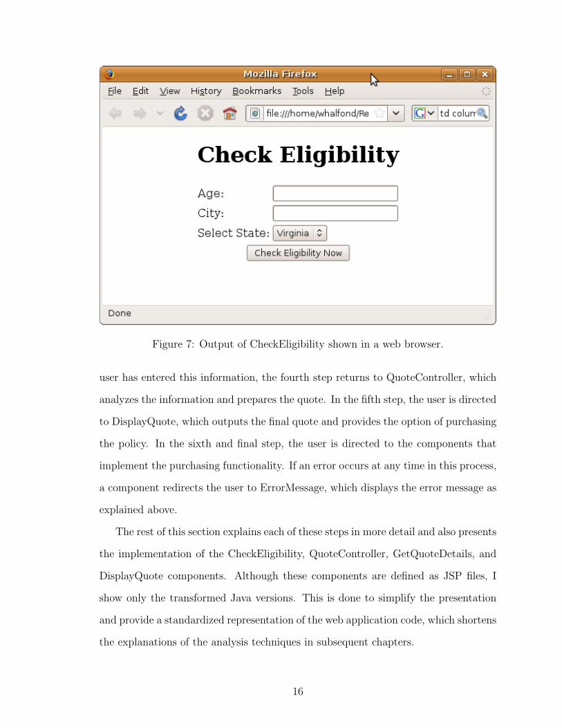
Figure 7: Output of CheckEligibility shown in a web browser.
user has entered this information, the fourth step returns to QuoteController, which
analyzes the information and prepares the quote. In the fifth step, the user is directed
to DisplayQuote, which outputs the final quote and provides the option of purchasing
the policy. In the sixth and final step, the user is directed to the components that
implement the purchasing functionality. If an error occurs at any time in this process,
a component redirects the user to ErrorMessage, which displays the error message as
explained above.
The rest of this section explains each of these steps in more detail and also presents
the implementation of the CheckEligibility, QuoteController, GetQuoteDetails, and
DisplayQuote components. Although these components are defined as JSP files, I
show only the transformed Java versions. This is done to simplify the presentation
and provide a standardized representation of the web application code, which shortens
the explanations of the analysis techniques in subsequent chapters.
16

1 public f ina l class C h e c k E l i g i b i l i t y j s p extends HttpJspPage {2 public void j s p S e r v i c e ( HttpServ letRequest request , HttpServletResponse re sponse )
{3 re sponse . out . wr i t e ( ”<html><body><h1>Check E l i g i b i l i t y </h1>” ) ;4 re sponse . out . wr i t e ( ”<form ac t i on =\”QuoteContro l l e r \” method=\”Get\”>” ) ;5 re sponse . out . wr i t e ( ”<input type=text name=age>” ) ;6 re sponse . out . wr i t e ( ”<input type=text name=c i ty >” ) ;7 re sponse . out . wr i t e ( ”<s e l e c t name=sta t e s >” ) ;8 for ( S t r ing s t a t e :ARRAY OF STATES) {9 re sponse . out . wr i t e ( ”<opt ion value=” + s t a t e + ”>” ) ;
10 }11 re sponse . out . wr i t e ( ”</s e l e c t >” ) ;12 re sponse . out . wr i t e ( ”<input type=hidden name=act i on value=\” C h e c k E l i g i b i l i t y \”>”
) ;13 re sponse . out . wr i t e ( ”<input type=submit>” ) ;14 re sponse . out . wr i t e ( ”</form>” ) ;15 re sponse . out . wr i t e ( ”</body></html>” ) ;16 }17 }
Figure 8: Implementation of servlet CheckEligibility.
Step 1
In the first step, the user visits the CheckEligibility component. This component
requests entry of the user’s age, city, and state of residence. CheckEligibility does
this by printing a set of HTML tags that direct the user’s web browser to display a
web form, which is an HTML based page that enables the user to enter and submit
data to a web application. More formally, a web form is defined as an HTML element
delimited by <form> tags. A web form can contain input fields, such as text input
boxes, radio buttons, and drop-down menu boxes, which allow users to enter data
directly into the web form via a web browser. The web form generated by CheckEl-
igibility is shown in Figure 7. It contains two input text boxes that request the end
user’s age and city of residence. It also contains a drop-down menu that allows the
user to select his state of residence. When the user clicks on the web form’s submit
button, the browser encodes the data in the web form’s input fields into name-value
pairs and invokes the target component specified by the web form’s HTML tag (this
is QuoteController, as explained below).
The Java code that implements CheckEligibility is shown in Figure 8. Only the
17

root method of CheckEligibility is shown. Line 3 outputs the opening HTML tags and
title of the HTML page. In the <form> tag, the target of the form-based invocation is
specified as QuoteController (via the action attribute), and the method request type
is specified as “GET” (via the method attribute). Lines 5 and 6 create <input> tags
that instruct the browser to display text boxes and allow the end-user to enter his age
and city of residence. The <select> tags generated at lines 7 and 11 together define
a combo drop-down box that allows the user the choose his state of residence. The
values in the combo box are generated in the loop at lines 8–10. A submit button is
created using the <input> tag at line 12. Finally, the closing HTML tags for <form>,
<body>, and <html> are generated at lines 13–14. All of the HTML generated by the
root method is sent to the end user and displayed to create the web form shown in
Figure 7.
Step 2
The second step is initiated by an invocation of QuoteController by CheckEligi-
bility. The invocation is as follows: http://www.host.com/QuoteController.jsp?
action=CheckEligibility&age=18&city=Atlanta&state=GA. This invocation de-
fines four parameters: action, age, city, and state. The component QuoteController
checks the values of these parameters and, if the checks pass, issues a command to
redirect the user to GetQuoteDetails.
The Java code that implements the second step is shown in lines 3–23 of Figure 9.
On receiving the invocation, QuoteController first calls a PF at line 4 to access the
value of “action.” (This name-value pair was set to “CheckEligibility” by CheckEli-
gibility at line 12 of Figure 8.) For this invocation, the condition at line 5 is true, so
QuoteController accesses the values of “age” and “state” at lines 6 and 7. If either of
these values fail the checks at lines 10 and 14, then at line 19 QuoteController redi-
rects the user to ErrorMessage with an invocation that contains the corresponding
18
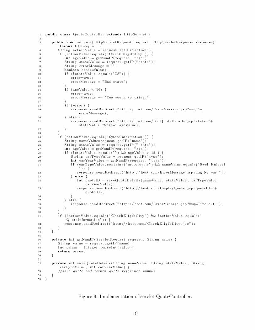
1 public class QuoteContro l l e r extends HttpServ l e t {2
3 public void s e r v i c e ( HttpServ letRequest request , HttpServletResponse re sponse )throws IOException {
4 St r ing act ionValue = reques t . getIP ( ” ac t i on ” ) ;5 i f ( act ionValue . equa l s ( ” C h e c k E l i g i b i l i t y ” ) ) {6 int ageValue = getNumIP( request , ”age ” ) ;7 St r ing stateValue = reques t . getIP ( ” s t a t e ” ) ;8 St r ing errorMessage = ”” ;9 boolean e r r o r=fa l se ;
10 i f ( ! s tateValue . equa l s ( ”GA” ) ) {11 e r r o r=true ;12 errorMessage = ”Bad s t a t e ” ;13 }14 i f ( ageValue < 16) {15 e r r o r=true ;16 errorMessage += ”Too young to dr i ve . ” ;17 }18 i f ( e r r o r ) {19 re sponse . sendRedi rect ( ” http :// host . com/ ErrorMessage . j sp ?msg=”+
errorMessage ) ;20 } else {21 re sponse . sendRedi rect ( ” http :// host . com/ GetQuoteDetai ls . j sp ? s t a t e=”+
stateValue+”&age=”+ageValue ) ;22 }23 }24 i f ( act ionValue . equa l s ( ” QuoteInformation ” ) ) {25 St r ing nameValue=reques t . getIP ( ”name” ) ;26 St r ing stateValue = reques t . getIP ( ” s t a t e ” ) ;27 int ageValue = getNumIP( request , ”age ” ) ;28 i f ( ! s tateValue . equa l s ( ”” ) && ageValue > 15 ) {29 St r ing carTypeValue = reque s t . getIP ( ” type ” ) ;30 int carYearValue = getNumIP( request , ” year ” ) ;31 i f ( carTypeValue . conta in s ( ” motorcyc le ” ) && nameValue . equa l s ( ” Evel Knieve l
” ) ) {32 re sponse . sendRedi rect ( ” http :// host . com/ ErrorMessage . j sp ?msg=No way . ” ) ;33 } else {34 int quoteID = saveQuoteDeta i l s ( nameValue , stateValue , carTypeValue ,
carYearValue ) ;35 re sponse . sendRedi rect ( ” http :// host . com/ DisplayQuote . j sp ? quoteID=”+
quoteID ) ;36 }37 } else {38 re sponse . sendRedi rect ( ” http :// host . com/ ErrorMessage . j sp ?msg=Time out . ” ) ;39 }40 }41 i f ( ! act ionValue . equa l s ( ” C h e c k E l i g i b i l i t y ” ) && ! act ionValue . equa l s ( ”
QuoteInformation ” ) ) {42 re sponse . sendRedi rect ( ” http :// host . com/ C h e c k E l i g i b i l i t y . j sp ” ) ;43 }44 }45
46 private int getNumIP( Serv l e tReques t request , S t r ing name) {47 St r ing value = reques t . getIP (name) ;48 int param = I n t e g e r . pa r s e In t ( va lue ) ;49 return param ;50 }51
52 private int saveQuoteDeta i l s ( S t r ing nameValue , S t r ing stateValue , S t r ingcarTypeValue , int carYearValue ) {
53 // save quote and return quote re f e r ence number54 }55 }
Figure 9: Implementation of servlet QuoteController.
19

1 public f ina l class GetQuoteDeta i l s j sp extends HttpJspPage {2 public void j s p S e r v i c e ( HttpServ letRequest request , HttpServletResponse re sponse )
{3 int ageValue = getNumIP( request , ”age ” ) ;4 St r ing stateValue = getIP ( request , ” s t a t e ” ) ;5 re sponse . out . wr i t e ( ”<html><body><h1>Get Quote Deta i l s </h1>” ) ;6 re sponse . out . wr i t e ( ”<form ac t i on =\”QuoteContro l l e r \” method=\”Get\”>” ) ;7 re sponse . out . wr i t e ( ”<input type=text name=name>” ) ;8 re sponse . out . wr i t e ( ”<input type=text name=type>” ) ;9 re sponse . out . wr i t e ( ”<input type=text name=year>” ) ;
10 i f ( ageValue <= 25) {11 re sponse . out . wr i t e ( ”<t ex ta r ea name=inc iden t s >” ) ;12 re sponse . out . wr i t e ( ” L i s t prev ious a c c i d e n t s and moving v i o l a t i o n s here . ” ) ;13 re sponse . out . wr i t e ( ”</textarea >” ) ;14 }15 re sponse . out . wr i t e ( ”<input type=hidden name=\” s t a t e \” value=” + stateValue + ”>
” ) ;16 re sponse . out . wr i t e ( ”<input type=hidden name=\”age \” value=” + ageValue + ”>” ) ;17 re sponse . out . wr i t e ( ”<input type=hidden name=QuoteInformation value=\”
GetQuoteDetai ls\”>” ) ;18 re sponse . out . wr i t e ( ”<input type=submit>” ) ;19 re sponse . out . wr i t e ( ”</form>” ) ;20 re sponse . out . wr i t e ( ”</body></html>” ) ;21 }22 }
Figure 10: Implementation of servlet GetQuoteDetails.
error messages. If both checks pass, at line 21 QuoteController redirects the user to
GetQuoteDetails with an invocation that contains “age” and “state” as name-value
pairs.
Step 3
The third step occurs when QuoteController invokes GetQuoteDetails. Following
with the example from the previous step, this invocation would be: http://www.
host.com/QuoteController.jsp?age=18&state=GA. Component GetQuoteDetails
displays a web form, customized according to the user’s age that prompts the user
for additional information about the policy he wants to purchase. Once the user has
entered in this information, the clicking of the submit button causes the browser to
invoke QuoteController with name-value pairs defined in the web form.
The Java code that implements the root method of GetQuoteDetails is shown in
Figure 10. At lines 3 and 4, GetQuoteDetails accesses two name-value pairs that
20

are part of the invocation received from QuoteController. Lines 5 creates the open-
ing HTML tags and the title of the web page. The opening tag of a web form is
generated at line 6. It specifies that the target of the web form based invocation is
QuoteController and the request method is “GET.” Lines 7, 8, and 9 create <input>
elements that allow the user to enter in values for his name, car type, and car year.
If the user specified that they are under 25, then the condition at line 25 is true and
a text area is displayed that prompts the user to list all accidents and tickets he may
have received. The values for the state and age parameters are saved in hidden fields
at lines 15 and 16. Hidden fields are a subtype of <input> tags that do not have a
graphical representation in a web form, but can hold a value that is used as a name-
value pair when the web form in submitted. Another hidden field is used at line 17
to store state information used by QuoteController. Finally, lines 18–20 generate a
submit button, and the closing form and HTML document tags.
Step 4
The fourth step is the invocation of QuoteController by GetQuoteDetails. The
invocation would be as follows: http://www.host.com/QuoteController.jsp?age=
18&state=GA&action=QuoteInformation&name=GJ&year=2001&type=Jeep. Quote-
Controller analyzes the values submitted by GetQuoteDetails, makes a check to ensure
that Evel Knievel2 is not trying to insure his motorcycle, prepares and saves the quote,
then finally redirects the user, via an invocation, to DisplayQuote, which displays the
final quote.
The Java code that implements this functionality in QuoteController is shows in
lines 3–5 and 24–40 of Figure 9. When QuoteController is invoked by GetQuoteDetails
the value of “action” is set to “GetQuoteDetails,” which causes the condition at line
5 to be false and the condition at line 24 to be true. QuoteController then accesses
2See http://en.wikipedia.org/wiki/Evel_Knievel for further information as to why an in-surance company might not want to insure Evel Knievel.
21

1 public f ina l class Disp layQuote j sp extends HttpJspPage {2 public void j s p S e r v i c e ( HttpServ letRequest request , HttpServletResponse re sponse )
{3 St r ing name = getIP ( request , ”name” ) ;4 St r ing quoteID = getIP ( request , ”quoteID” ) ;5 i f ( isAlphaNumeric ( quoteID ) {6 re sponse . out . wr i t e ( ”<html><body><h1>Your Per sona l i z ed Quote</h1>” ) ;7 Connection con = new Connection ( ” l o c a l h o s t : quoteDatabase ” ) ;8 Resu l tSet r s = con . executeQuery ( ” s e l e c t ∗ from quotes where name = ’ ” + name
+ ” ’ quoteID=” + quoteID ) ;9 Quote q = new Quote ( r s [ 0 ] ) ;
10 re sponse . out . wr i t e ( ”<b>Name:</b> ” + q . getName ( ) ) ;11 re sponse . out . wr i t e ( ”<b>Age:</b> ” + q . getAge ( ) ) ;12 re sponse . out . wr i t e ( ”<b>Car Type:</b> ” + q . getCarType ( ) ) ;13 re sponse . out . wr i t e ( ”<b>Car Year :</b> ” + q . getCarYear ( ) ) ;14 re sponse . out . wr i t e ( ”<b>City :</b> ” + q . getCity ( ) ) ;15 re sponse . out . wr i t e ( ”<b>State :</b> ” + q . ge tS ta t e ( ) ) ;16 re sponse . out . wr i t e ( ”<b>Your Quote:</b> ” + q . getQuotePrice ( ) ) ;17 re sponse . out . wr i t e ( ”<a h r e f = http :// host . com/ BuyPolicy . j sp ? quoteID=”+
quoteID+”&name=”+q . getName ( )+”>Purchase Pol icy </a>” ) ;18 re sponse . out . wr i t e ( ”</body></html>” ) ;19 } else {20 re sponse . sendRedi rect ( ” http :// host . com/ ErrorMessage . j sp ?msg=I n v a l i d ID . ” ) ;21 }22 }23 }
Figure 11: Implementation of servlet DisplayQuote.
“name,” “state,” and “age” at lines 25–27. If the check on “state” and “age” passes,
QuoteController accesses the values of “type” and “year”. At line 31, QuoteController
checks whether Evel Knievel is trying to insure his motorcycle. If he is, then line 32
redirects him to ErrorMessage via an invocation, and no quote is generated; otherwise,
at lines 34 and 35, the quote details are saved, and the user is redirected via an
invocation to DisplayQuote. In this case, the invocation contains a “quoteID” that
references the prepared quote to be displayed.
Step 5
The fifth step is the invocation of DisplayQuote by QuoteController. The compo-
nent DisplayQuote retrieves the prepared quote and displays it to the end user.
The Java code that implements the root method of DisplayQuote is shown in
Figure 11. At lines 3 and 4 the servlet first accesses two name-value pairs, “quoteID”
and “name”. The value of “quoteID” is checked, at line 5, to ensure that it is an
22

alphanumeric string. If this check passes, line 6 generates the opening HTML tags
and title for the page. Lines 7–9 search the database for the quote associated with the
user and then create a Quote object that encapsulates the information in the quote.
Lines 10–16 display the quote-related information and the price of the policy. A link
to purchase the policy is generated at line 17. Finally the closing HTML tags are
generated at line 18. If “quoteID” fails the check at line 5, then line 20 redirects the
user to ErrorMessage, which displays an error message.
Step 6
The sixth step is triggered when a user clicks on the link generated by Dis-
playQuote at line 17 of Figure 11. Clicking this link allows the user to purchase
the quoted insurance policy. The implementation of this and subsequent steps is not
part of the example.
23

CHAPTER III
SUBJECT WEB APPLICATIONS
This chapter introduces a set of web applications that are used throughout my disser-
tation as experiment subjects. These applications were chosen for several reasons: (1)
They come from different sources including commercial companies, student-developed
projects, and open-source projects; (2) the applications have been widely used in re-
lated work or downloaded frequently; (3) the General-Purpose Programming Language
(GPL) of the applications is Java, which is the target language of my analyses’ im-
plementation; (4) the applications are implemented using several different Java-based
technologies including: Java Server Pages (JSP), servlet class implementations, and
proprietary frameworks; (5) several applications contain known vulnerabilities; and
(6) several applications are mature and have multiple versions.
The set of subjects is comprised of ten Java-based web applications. Five of them:
Bookstore, Classifieds, Employee Directory, Events, and Portal are commercial open-
source applications available from GotoCode.1 These applications are based on a
mix of JSP pages and classes written in Java. Checkers and OfficeTalk are student-
developed projects that have been used in related work [29]. These two applications
directly implement Java servlet classes in order to provide all of the required func-
tionality of a web application. Filelister, JWMA, and Daffodil are also open-source
projects that have been used in related work on detecting vulnerabilities in web appli-
cations [52]. All three contain known vulnerabilities and are part of the SecuriBench
suite of benchmark web applications [51]. They are available on Sourceforge2 and
their different versions have over 100 thousand downloads combined. These three
1http://www.gotocode.com/2http://www.sourceforge.net/
24

applications use a mix of JSP, servlet class implementations, and proprietary frame-
works in their implementation.
Table 1 shows detailed information for each of the subject web applications. For
each subject, the table lists a brief description of the intended use of the application
(Description), the non-commented lines of Java code (LOC ), the number of classes
that implement a servlet interface (Servlets), and the number of other classes in the
web application (Other). As can be seen from the data in the table, the number
of lines of code of the applications runs from 54 hundred to over 29 thousand and
their size in terms of the total number of classes ranges from 12 to 129. Although
these subjects represent small to medium sized web applications, as I discuss in later
chapters, the analyses can scale to larger web applications. Smaller sized web appli-
cations were used in the evaluations to simplify the manual checking of the results.
Furthermore, all of the subject applications contain characteristics of modern web
applications that make the application of traditional quality assurance techniques
difficult, such as dynamically generated output and interfaces determined at runtime.
25

Table 1: Subject programs for the empirical studies.
Subject Description LOCClasses
Servlets Other
Bookstore Browse and purchase books 19,402 27 1
Checkers Checkers game 5,415 33 28
Classifieds Post and manage ads 10,702 19 1
Daffodil Customer relations management 19,305 70 59
Employee Directory Maintain employee information 5,529 11 1
Events Manage calendar of events 7,164 13 1
Filelister File browser 8,630 10 31
JWMA Webmail 29,402 20 77
Office Talk Inter-office communication 4,670 38 27
Portal Manage group websites 16,089 28 1
26

CHAPTER IV
COMPONENT IDENTIFICATION ANALYSIS
The identification of components in a web application is important for effective testing
and analysis. In general, the implementation of a web application is comprises a col-
lection of modules, framework libraries, and Hyper-Text Markup Language (HTML)
content. Components represent a special subset of the modules that are directly
addressable by a Hyper Text Transfer Protocol (HTTP) request. Since a web appli-
cation’s interaction with the end user begins via an HTTP request, the components
are analogous to the public entry methods of traditional software (e.g., the main()
method in an application). This makes the identification of the components impor-
tant: For analyses, the components provide additional important semantic informa-
tion; for quality assurance tasks, they represent the point at which tasks, such as
verification (Chapter 8) and test-input generation (Chapter 7), should start interac-
tion with the application. More generally, although the identification of components
is not directly used in a quality assurance technique, the analyses presented in Chap-
ters 5 and 6 use information about components as a means of identifying where to
start their own analyses.
Unfortunately, the identification of web application components is not as straight-
forward as identifying entry methods of traditional software. The problem is that
each web application framework has its own requirements for the implementation of
a component. Often these differences are minor; for example, a component might be
required to implement only a specially named function or interface. For most lan-
guages, there is a multitude of implementation constructs that can be used to satisfy
these requirements. This makes it difficult for developers to use manual inspection of
27

the code and motivates the need for automated analysis to identify components. It
can also be difficult to determine the set of HTTP request methods that are supported
by a component. Although in some web frameworks the required request methods
can be explicitly defined, in most the request method is implied by the methods im-
plemented in an interface or by the way input data is accessed. The identification of
the supported request methods is important because it specifies how parameters in an
HTTP request must be packaged in order to be accessed correctly by the component.
In Section 4.1, I present a general analysis technique that can identify the compo-
nents of a web application, each component’s root methods, and the HTTP request
methods supported by each root method. The analysis works for a broad range of
web application frameworks, including those written in PHP, Java, Perl, and Python.
Customization for a particular framework requires the definition of a set of functions
that handles the peculiarities of each framework. In Section 4.2, I present one such
customization for the Java Platform Enterprise Edition (JEE) framework, which is
the framework used by my subject applications.
4.1 Algorithm
The goal of the component identification analysis is to identify components, root
methods, and each root method’s supported HTTP request methods. From a high
level, the analysis processes each file in the web application and determines if it
is (1) an HTML page, (2) a configuration file, or (3) a file written in the general
purpose language of the web framework. In the first case, the analysis simply extracts
the name of the HTML file and adds it to the list of components. In the second
case, the analysis invokes custom handling, which updates the list of components
based on the contents of the configuration file. In the third case, the analysis parses
the file and then determines whether the implementation represents a component.
Finally, after all files are processed, the analysis returns a set of tuples, each one of
28

Algorithm 1 Identify Components
Input: files: all files that implement the web applicationOutput: components: set of triplets describing components, root methods, and their
supported HTTP request methods1: for all file ∈ files do2: if file is an HTML file then3: components← components ∪ {〈nameOf(file), /,{GET}〉}4: else if isConfigurationFile(file) then5: processConfigurationFile(components, file)6: else if isLanguageFile(file) then7: modules← parse(file)8: for all module ∈ modules do9: for all method ∈ methodsOf(module) do
10: if isComponentRootMethod(method) then11: components ← components ∪ {〈nameOf(file), method,
{requestType(method)}〉}12: end if13: end for14: end for15: end if16: end for17: return components
the form 〈Cname, Mname, {h1, h2, . . . , hn}〉. In this tuple, Cname represents the file
path of a component, Mname is the name of the root method of the component, and
{h1, h2, . . . , hn} is the set of HTTP request methods supported by the root method.
Line by Line Explanation of Algorithm
Algorithm 1 shows Identify Components, which implements my component
identification analysis. The input to Identify Components is the set of all
files that implement a web application. The output is a set of triplets,
each of which contains the name of the component, a root method of the
component, and the corresponding request methods supported by that root
method. The algorithm assumes the implementation of several framework-specific
functions: isConfigurationFile, processConfigurationFile, isLanguageFile,
29

parse, nameOf, methodsOf, requestType, and isComponentRootMethod. The spe-
cialization of these functions for the JEE framework is explained in Section 4.2.
Processing in Identify Components begins at line 1, which iterates over each file in
the input. At line 2, the analysis checks whether file is a static HTML page. If this is
the case, at line 3 the name of the HTML file is used as the component name, and the
default request method for HTML files (GET) is added to components. The special
symbol “/” is used to denote that the root method is the name of the resource.1 At
line 4, the analysis checks whether file is a configuration file. Here a framework-
customizable function, isConfigurationFile, is utilized and a similar framework-
specific function, processConfigurationFile, updates components based on the
contents of the configuration file at line 5. This functionality is based entirely on
the framework used, since some frameworks provide partial component definitions or
entry point definitions in a configuration file. At line 6, the analysis checks whether
file is written in the general purpose programming language of the web framework.
Here again, this is customized per framework. If the check passes, at line 7 file is
parsed using a language specific parser to identify the defined modules (e.g., classes in
a Java file). The analysis iterates over each module’s methods in lines 9–13. At line
10, if the method signature matches one of the framework’s known root methods, then
components is updated at line 11: The components set is updated with the name
of the component and the root method is set to the method name. A framework-
specific function, requestType, returns the HTTP request type that corresponds to
that root method. Lastly, line 17 returns the list of components and the discovered
information.
1This notation is widely used in HTTP to denote the default root entry point of a component.
30

4.2 Implementation
The implementation of the component identification analysis is written in Java for
web applications developed using the JEE framework. The specialization of Identify
Components is accomplished by implementing the list of framework-specific functions.
In the following list, I enumerate each of these and briefly explain how they are
implemented for the JEE framework.
• isConfigurationFile: JEE configuration files are XML-based files that im-
plement a certain document type definition (DTD). If a file implements this
DTD, it is treated as a configuration file.
• processConfigurationFile: In the JEE framework, configuration files contain
mapping information between URL file paths and the corresponding class to be
executed. This information is read in and stored for use by the nameOf function.
• isLanguageFile: Files that end with “.jsp” or “.java”
• parse: Parser for the Java language and JEE extensions. Returns the classes
defined in the file. This is implemented by leveraging the Soot static analysis
framework.2
• methodsOf: Done by walking the parse tree and identifying all public method
definitions. This is implemented by leveraging the Soot static analysis frame-
work.2
• isComponentRootMethod: For a method m, if the containing class of m im-
plements one of the servlet interfaces and m’s signature matches one of the
predefined servlet root methods, then m is a component root method. This is
implemented by leveraging the Soot static analysis framework.2
2http://www.sable.mcgill.ca/soot/
31

• nameOf: Returns either the name of the HTML file or the name of the URL
mapped to the class implemented in the file. For the JEE framework, the
mapping between a class and the URL file path used to access it is defined in a
specific configuration file, so this is a simple lookup.
• requestType: Matches the method name with the types of request methods
that it can handle. This is accomplished by using a pre-built lookup table that
contains a mapping between special root method names in the JEE framework
and the HTTP request methods they must support.
32

CHAPTER V
INTERFACE ANALYSIS
Interfaces are used extensively in modern web applications, and their identification is
important for many quality assurance tasks. To provide the advanced functionality
users have come to expect in modern web applications, components must communi-
cate extensively with each other and with end users. This communication is done
by sending Hyper Text Transfer Protocol (HTTP) requests that target the accepted
interfaces of a component. As a result, these interfaces are also used extensively
by quality assurance techniques. For example, to create effective test inputs, it is
necessary to know the names and groupings of the parameters accessed by a web
application. This information needs to be identified before any type of input gener-
ation strategy can be employed. Other techniques, such as penetration testing and
invocation verification, also make use of interface information to detect errors and
vulnerabilities in web applications.
Identifying interfaces in web applications is difficult. For traditional software, it
is normal to have method signatures that provide a significant amount of information
about the interfaces of a software module. These signatures include information, such
as the name of the method, its set of named parameters, and domain information
about each of the parameters. As explained in Chapter 2, web application interfaces
are not explicitly defined in this manner. Instead, the set of named parameters in an
interface is implicitly defined by the set of parameters accessed by a component during
a given execution. Similarly, the domain information for each of these parameters is
implied by the domain-constraining operations performed on the parameter values.
Both the set of accessed parameters and domain-constraining operations can vary
33
along different paths of a component. This complicates the identification of interfaces
and interface domain constraints (IDC).
Many current approaches for identifying interface information have limitations
that reduce their effectiveness. Generally, proposed techniques are either incomplete
with respect to identifying interfaces or do not discover enough information to be use-
ful for many quality assurance tasks. For small web applications, it is possible to use
manual inspection to identify interfaces. However, for larger and more complex web
applications, multiple layers of abstraction and the use of frameworks can obscure the
intended function of the components. Several approaches rely on developer-provided
interface specifications [8, 41, 67]. Although developer-provided specifications can
accurately specify the intended behavior of an application, they are time-consuming
to produce and may not be consistent with the implementation. Other approaches
interact with the web application at runtime and use dynamic analysis to identify
interfaces exposed during the interaction [25, 38]. The main limitation of these ap-
proaches is that they cannot provide any guarantees of completeness, as they may
not identify hidden interfaces or interfaces that are not accessed during the observed
executions. Lastly, another approach uses static analysis to identify interface-related
information [23]. However, this approach does not provide interface domain con-
straints and does not precisely group name-value pairs into logical interfaces.
My work in interface identification analysis led to the development of two new
techniques for identifying the interfaces of a web application. Both techniques are
based on static analysis of a web application’s code. The first technique is based on a
multi-phase iterative data-flow analysis. It computes a conservative approximation of
the interface information of a web application. This technique can be applied to any
web application that accesses name-value pairs by using calls to a parameter function
(PF). Since almost all web applications are written using frameworks that define a set
of PFs, in practice, this technique can be easily applied to almost all web applications.
34

However, in some cases, quality assurance techniques need more precise interface
information than can be provided by the data-flow based approach. To address this
situation, I developed a second technique, which is based on symbolic execution.
The information provided by this technique is more precise, but it can potentially
require more developer intervention to successfully analyze a web application. For
many quality assurance tasks, this increased effort can be worth the time, since the
increased precision results in more accurate results and significant improvements in
efficiency.
In the rest of this chapter, I present both techniques for interface identification.
This includes the algorithms, detailed line-by-line explanations, and illustrations with
the example web application. Section 5.1 describes the first technique, and the second
technique is presented in Section 5.2. I compare and contrast the two techniques in
terms of their trade-offs in Section 5.3.
5.1 Iterative Data-flow Based Analysis
This section describes my iterative data-flow analysis based approach for identifying
the interfaces of a web application. Section 5.1.1 presents the algorithms that define
the two phases of the technique, and Section 5.1.2 describes the architecture of a tool
that implements my algorithms for Java-based web applications.
5.1.1 Algorithm
My data-flow based algorithm for identifying the interfaces of a web application has
two phases. The first phase computes domain information for name-value pairs ac-
cessed by a component. The second phase identifies the names associated with each
name-value pair and groups them into logical interfaces based on the control flow
of the component. In the following sections, I explain each of these phases in more
depth and illustrate how they work using the example web application presented in
Chapter 2. Note that in the rest of the discussion I assume that (1) there are no global
35

variables in the applications under analysis, (2) each node in the program contains
only one definition, and (3) the inter-procedural control-flow graph (ICFG) does not
contain control-flow edges associated with thrown exceptions. I make these assump-
tions only to simplify the presentation of the algorithms, and they do not limit the
applicability of the approach in any way. For the first two assumptions, although
none of the subjects violated them, any program could be automatically transformed
so that it satisfies both. For the third assumption, it is sufficient to ignore control-flow
edges in the ICFG that are associated with exceptions.
5.1.1.1 Phase 1
In the first phase, my approach analyzes each component of the web application and
outputs domain information for the name-value pairs accessed within the component.
From a high level, the approach works by analyzing each PF call site within a com-
ponent and following the sequence of definitions and uses that starts with the return
value of the PF call site. For example, if a call site is of the form value = PF (name),
then the approach identifies all uses of value. If one of these uses of value is found
in another assignment, this process is repeated. For example, if the next use is
value′ = f(value), then the approach uses the semantics of f() to identify domain
information about parameter name and then examines the uses of value′. By follow-
ing this sequence, the approach can examine all direct and indirect uses of the return
value to determine if it is being used within the context of a domain-constraining
operation.
My approach recognizes two types of domain-constraining operations: (1) compar-
ison of the return value with hard-coded constants, and (2) conversion of the return
value to numeric types. For example, if a variable that contains the return value of
the PF call is used as a parameter to a function that converts strings to a numeric
value, the approach infers that the domain type of the value is numeric. Similarly, if a
36

variable that contains the return value of the PF call is compared against a constant
value, the approach infers that this constant value is a special value in the domain
of the parameter. More complex and varied types of domain-constraining operations
can be considered if the underlying web application framework has defined functions
that represent conversions to those types.
If domain-constraining operations are present, the approach annotates the com-
ponent’s ICFG with the identified domain information. The approach annotates two
kinds of nodes in the ICFG: (1) nodes that contain a call to a PF and (2) return sites
from methods that either directly invoke a PF or indirectly invoke a PF through a
chain of method calls. An annotation for a node contains three elements: (1) the
location of the original PF call, (2) the domain type expected for all parameter val-
ues used at that node, and (3) special values in the domain of the parameter used
at that node. After each PF call site is processed, the output of the algorithm is an
ICFG with annotations that describe the domain of the parameters accessed by the
component.
The runtime complexity of the Phase 1 analysis is dominated by following the
sequences of definitions and uses that originate with the return value of each PF
call. In the worst case, following this sequence requires visiting every node in the
ICFG once for each PF in the web application. Note that a check in the algorithm
prevents the following of cyclical dependencies. Therefore, the runtime complexity of
the analysis is O(pn) where p is the number of PF calls in the web application and n
is the number of nodes in the ICFG.
Line by Line Explanation of Algorithm
Algorithm 2 shows a function GetDomainInfo, which computes the domain in-
formation of a web application. The input to GetDomainInfo is the ICFG of the
web application and its output is the ICFG annotated with the computed domain
37

Algorithm 2 GetDomainInfo
Input: ICFG: Inter-procedural control flow graph of the web applicationOutput: ICFG′: ICFG annotated with domain information
1: for all node ∈ PF call site nodes of ICFG do2: newannot← new annotation3: newannot.pf ← node4: newannot.type← ANY
5: newannot.values← {}6: associate newannot with node7: GDI(node, null, node, {})8: end for9: return ICFG′
information. GetDomainInfo uses the ICFG to identify all PF call sites in the web
application (line 1). For each call site, node, GetDomainInfo creates a new annota-
tion (line 2), initializes the annotation’s pf field to node (lines 3), its type field to
ANY (line 4), and its values field to the empty set (line 5). The new annotation is
then associated with node in the ICFG (line 6). Finally, GetDomainInfo begins the
analysis of node by calling an auxiliary function GDI (line 7). When all PF calls have
been processed, GetDomainInfo returns the annotated ICFG.
Algorithm 3 shows GDI, which recursively follows the sequence of definitions and
uses that begins with a PF call site. GDI takes four parameters as input: node is the
node to be analyzed; var is the variable that stores the value derived from the original
PF call site and that is used at node; root node is the node to be annotated with the
discovered domain information; and visited nodes is the set of nodes encountered in
the path being traversed. To understand the algorithm, it is important to note that,
by construction, the statement represented by node is always a use of variable var.
In turn, var always stores the original return value or a value that was derived from
the original value. GDI has no output, but its side effect is to annotate the ICFG
being analyzed by GetDomainInfo.
GDI first checks to ensure that node is not in the set of visited nodes (line 1). This
check ensures that cyclic data dependencies are explored only once in a path. If node
38

Algorithm 3 GDIInput: node: current node to examine
var: variable storing the value used at noderoot node: node to be annotatedvisited nodes: nodes visited along current path
1: if node 6∈ visited nodes then2: if node is a return node then3: returnsites← possible return sites of node4: for all retsite ∈ returnsites do5: newannot← root node’s annotation6: associate newannot with node retsite7: GDI(retsite, null, retsite, visited nodes ∪ {node})8: end for9: else
10: if node compares var with a constant then11: compval← value used in the comparison12: addValueToAnnotation(root node, compval)13: else if node converts var to another type then14: type← target type of the convert operation15: setDomainTypeInAnnotation(root node, type)16: end if17: if node contains a definition of a variable then18: var′ ← variable defined at node19: for all n ∈ DUchain(var′, node) do20: GDI(n, var′, root node, visited nodes ∪ {node})21: end for22: end if23: end if24: end if
is a return node (line 2), GDI identifies all return sites for the method that contains
node (line 3). For each return site (line 4), GDI copies root node’s annotation (line
5), and associates the annotation with node retsite (line 6). Annotations are copied
to allow the domain information to be context-sensitive, which improves the precision
of the derived information. Finally, GDI invokes itself recursively on the return site,
updating the visited nodes set appropriately (line 7).
If node is not a return node (line 2), then GDI checks if node is a comparison with
a constant value (line 10). If it is, GDI identifies the constant value (line 11) and adds
it the set of values in the annotation associated with root node (line 12). If node is
not a comparison statement (line 10), then GDI checks if node is a type conversion
statement. If it is, GDI identifies the target type of the conversion operation (line
14) and updates the domain type of the annotation associated with root node (line
39

15). Finally, GDI checks if node contains a definition of another variable (line 17).
If it does, GDI identifies the new definition (line 18). For each node n that uses this
new definition (line 19), GDI invokes itself recursively, updating the visited nodes
set appropriately (line 20). (The function DUchain(v, n) returns the set of nodes
where the definition of variable v at node n is used without any other superseding
definitions [4].)
Illustration with Example Web Application
To illustrate the first phase with an example, I explain the execution of Get-
DomainInfo on QuoteController. The source code of QuoteController is shown in
Figure 121 and its corresponding ICFG is shown in Figure 13. Each node in the
ICFG is numbered based on the source code line number it represents. In the sub-
sequent explanation, I distinguish lines of the algorithm and ICFG by referring to
each line n in the algorithm as An and each node n of the ICFG as Nn. For this
illustration, I use the PF at node N48 as a representative example; other PFs that
would be analyzed are at nodes N4, N7, N25, N26, and N29. GetDomainInfo begins
the analysis by initializing a new empty annotation for the PF and then calling:
GDI(N48, null, N48, {})
On this iteration, node N48 has not been analyzed yet, so it passes the check at line A1
of GDI. The conditions at lines A2, A10, and A13 are false, so the analysis continues
at line A17, whose condition evaluates to true. At line A18, GDI identifies the variable
defined at node N48 as value. At line A19 it identifies node N49 as the next use of
value, so it calls itself recursively:
GDI(N49, value, N48, {N48})
1This figure is a duplicate of Figure 9. It is reproduced to make referencing easier for readers.
40

1 public class QuoteContro l l e r extends HttpServ l e t {2
3 public void s e r v i c e ( HttpServ letRequest request , HttpServletResponse re sponse )throws IOException {
4 St r ing act ionValue = reques t . getIP ( ” ac t i on ” ) ;5 i f ( act ionValue . equa l s ( ” C h e c k E l i g i b i l i t y ” ) ) {6 int ageValue = getNumIP( request , ”age ” ) ;7 St r ing stateValue = reques t . getIP ( ” s t a t e ” ) ;8 St r ing errorMessage = ”” ;9 boolean e r r o r=fa l se ;
10 i f ( ! s tateValue . equa l s ( ”GA” ) ) {11 e r r o r=true ;12 errorMessage = ”Bad s t a t e ” ;13 }14 i f ( ageValue < 16) {15 e r r o r=true ;16 errorMessage += ”Too young to dr i ve . ” ;17 }18 i f ( e r r o r ) {19 re sponse . sendRedi rect ( ” http :// host . com/ ErrorMessage . j sp ?msg=”+
errorMessage ) ;20 } else {21 re sponse . sendRedi rect ( ” http :// host . com/ GetQuoteDetai ls . j sp ? s t a t e=”+
stateValue+”&age=”+ageValue ) ;22 }23 }24 i f ( act ionValue . equa l s ( ” QuoteInformation ” ) ) {25 St r ing nameValue=reques t . getIP ( ”name” ) ;26 St r ing stateValue = reques t . getIP ( ” s t a t e ” ) ;27 int ageValue = getNumIP( request , ”age ” ) ;28 i f ( ! s tateValue . equa l s ( ”” ) && ageValue > 15 ) {29 St r ing carTypeValue = reque s t . getIP ( ” type ” ) ;30 int carYearValue = getNumIP( request , ” year ” ) ;31 i f ( carTypeValue . conta in s ( ” motorcyc le ” ) && nameValue . equa l s ( ” Evel Knieve l
” ) ) {32 re sponse . sendRedi rect ( ” http :// host . com/ ErrorMessage . j sp ?msg=No way . ” ) ;33 } else {34 int quoteID = saveQuoteDeta i l s ( nameValue , stateValue , carTypeValue ,
carYearValue ) ;35 re sponse . sendRedi rect ( ” http :// host . com/ DisplayQuote . j sp ? quoteID=”+
quoteID ) ;36 }37 } else {38 re sponse . sendRedi rect ( ” http :// host . com/ ErrorMessage . j sp ?msg=Time out . ” ) ;39 }40 }41 i f ( ! act ionValue . equa l s ( ” C h e c k E l i g i b i l i t y ” ) && ! act ionValue . equa l s ( ”
QuoteInformation ” ) ) {42 re sponse . sendRedi rect ( ” http :// host . com/ C h e c k E l i g i b i l i t y . j sp ” ) ;43 }44 }45
46 private int getNumIP( Serv l e tReques t request , S t r ing name) {47 St r ing value = reques t . getIP (name) ;48 int param = I n t e g e r . pa r s e In t ( va lue ) ;49 return param ;50 }51
52 private int saveQuoteDeta i l s ( S t r ing nameValue , S t r ing stateValue , S t r ingcarTypeValue , int carYearValue ) {
53 // save quote and return quote re f e r ence number54 }55 }
Figure 12: Implementation of servlet QuoteController.
41
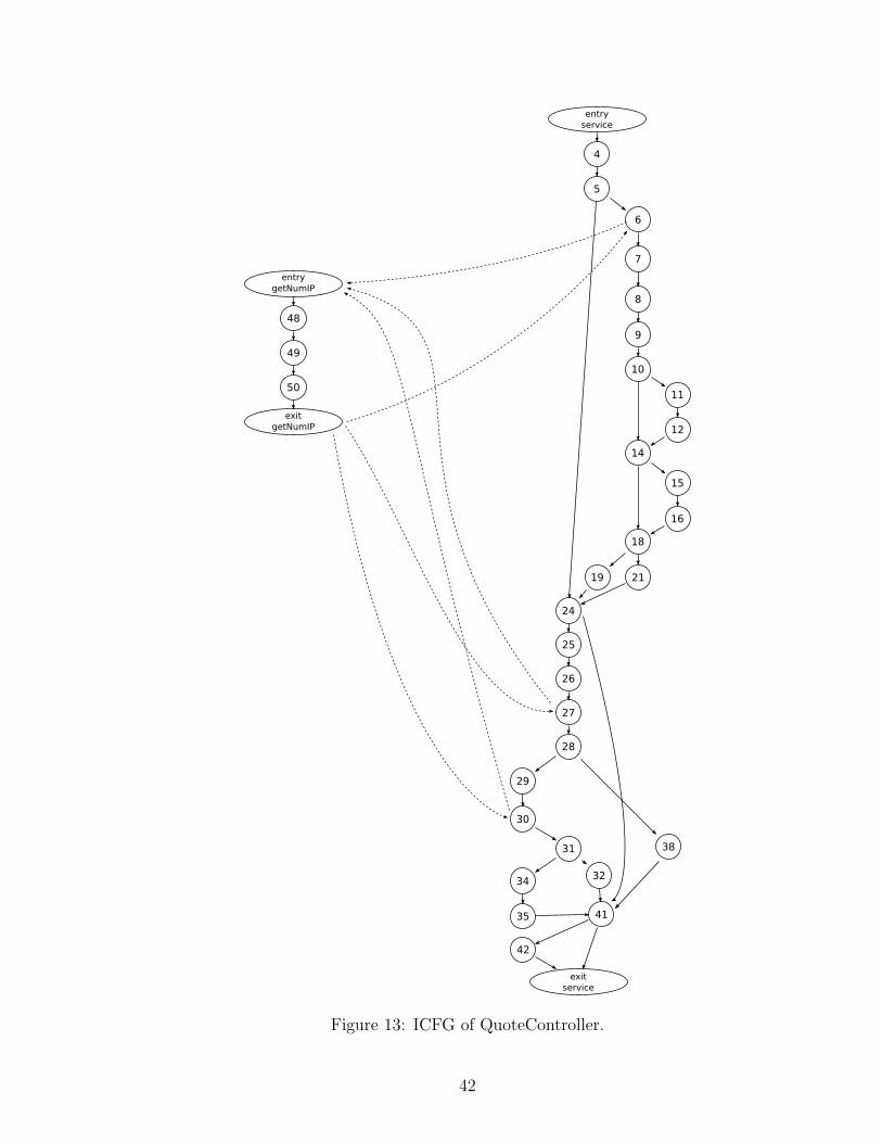
exitservice
4
5
6
7
8
9
10
11
12
14
15
16
18
2119
24
48
49
50
25
26
27
28
29
30
31
3234
35
38
41
42
entryservice
entrygetNumIP
exitgetNumIP
Figure 13: ICFG of QuoteController.
42

On this iteration, the condition at line A13 is true. GDI identifies the target type as
Integer and updates the annotation at node N48 accordingly. The condition at line
A17 is also true, so GDI identifies the variable defined at node N49 as param and the
next use of that variable at node N50. GDI then calls itself recursively:
GDI(N50, param, N48, {N48, N49})
On this iteration of GDI, the condition at line A2 is true, since node N50 is a return
statement. GDI identifies nodes N6, N27, and N30 as possible return sites and, at
line A6, assigns to them the same annotation as that of node N48. (At this point in
the example, the annotation specifies that the value must be an Integer.) GDI then
makes three recursive calls:
1) GDI(N6, null, N6, {N48, N49, N50})
2) GDI(N27, null, N27, {N48, N49, N50})
3) GDI(N30, null, N30, {N48, N49, N50}
On the first call, the conditions at lines A2, A10, and A13 are false, but the one at line
A17 is true. GDI identifies ageValue as the new definition, and node N14 as the next
use of ageValue. GDI then calls itself recursively:
GDI(N14, ageValue, N6, {N6, N48, N49, N50})
On this iteration, the condition at line A10 is true. GDI identifies “16” as the relevant
value and updates the annotation at node N6 to include it in the domain information.
The condition at line A17 is true, but there are no further uses of ageValue, so no
additional calls to GDI are made. Note that the reference to ageValue at node N28
is actually a reference to a different variable.
On the second call listed earlier, the conditions at lines A2, A10, and A13 are false,
but the one at line A17 is true. GDI identifies ageValue as the new definition, and
node N28 as the next use of ageValue. GDI then calls itself recursively:
43

GDI(N28, ageValue, N27, {N27, N48, N49, N50})
On this iteration, the condition at line A10 is true. GDI identifies “15” as the relevant
value and updates the annotation at node N27 to include it in the domain information.
The condition at line A17 is true, but there are no further uses of ageValue so no
additional calls to GDI are made.
On the third call listed earlier, the conditions at lines A2, A10, and A13 are false,
but the one at line A17 is true. GDI identifies carYearValue as the new definition.
This is a use as an argument to a non domain-constraining operation, so GDI identifies
the next use as the argument inside the method SaveQuoteDetails and follows the
sequence of definitions and uses into the method. Since SaveQuoteDetails is not
part of the example code, I do not consider it further.
At this point, the analysis of the PF at node N48 is complete and there are anno-
tations at nodes N6, N27, N30, and N48 with a domain type of Integer. Additionally,
node N6 has “16” as a relevant value, and node N27 has “15” as a relevant value.
The output of GetDomainInfo is shown in Figure 14. This figure shows the ICFG
from Figure 13 with the annotations generated during the Phase 1 analysis. This
includes the annotations that were explained in the illustration (nodes N6, N27, N30,
and N48) and the annotations that were created as a results of the PFs at nodes N4,
N7, N25, N26, and N29.
5.1.1.2 Phase 2
In the second phase, my approach analyzes each component’s annotated ICFG to
identify the name associated with each name-value pair, groups names into logical in-
terfaces, and associates domain information with each name. Intuitively, the approach
works by grouping sets of name-value pairs accessed along the same path into an in-
terface and associating any domain information on that path with the corresponding
name-value pairs.
44

pf: 4type: String values: {"CheckEligibility", "QuoteInformation"}
pf: 7type: String values: {"GA"}
pf: 25type: String values: {"Evel Knievel"}
pf: 26type: String values: {}
pf: 29type: String values: {"motorcycle"}
exitservice
pf: 48type: Integer values: {}
pf: 48type: Integer values: {16}
pf: 48type: Integer values: {15}
pf: 48type: Integer values: {}
4
5
6
7
8
9
10
11
12
14
15
16
18
2119
24
48
49
50
25
26
27
28
29
30
31
3234
35
38
41
42
entryservice
entrygetNumIP
exitgetNumIP
Figure 14: Annotated ICFG of QuoteController.
45

To avoid the potentially exponential cost of analyzing each path individually, the
approach computes method summaries that can be reused whenever it analyzes code
that calls a method that has already been analyzed. The method summaries also
allow the analysis to be context-sensitive, as relevant information from the call site
can be substituted in to the summary. To ensure that a method is processed before
any method that calls it, the approach processes each method in reverse topological
order with respect to the call graph. Groups of methods that call each other are ana-
lyzed together as one “super-method.” Within each method, the approach computes
summary information using a worklist-based forward iterative data-flow analysis [48].
Each summary contains sets of name-value pairs that are on a path from the entry
to the exit of the method. When all methods in the ICFG have been processed, the
output is the summary of the component’s root methods.
The core of Phase 2 is the iterative data-flow analysis that summarizes each
method of the web application. This analysis converges on a fixed point for two
reasons: (1) The value domain for the sets in the data flow equations is finite, it can
only include those nodes that either directly or indirectly access a name-value pair
(which is at most the number of nodes n in the web application’s ICFG); and (2)
the transfer function is monotonic because no values are removed from the calculated
data-flow sets. The runtime complexity of this analysis is, like most iterative data-
flow analyses, dependent on the number of nested loops in the code [44]. In the worst
case, the number of nested loops is equivalent to the number of nodes n in the web
application’s ICFG. Each nested loop could cause the analysis to iterate over each of
the nodes in the ICFG. Therefore, the runtime complexity of Phase 2 is O(n2). Note
that I assume the nodes are processed in reverse postorder.
One additional runtime cost for Phase 2 is the use of string analysis in the resolve
function to determine the name of each name-value pair. The string analysis values
46

Algorithm 4 ExtractInterfaces
Input: ICFG: annotated ICFG produced by GetDomainInfoCG: call graph for the component
Output: summary : list of interfaces exposed by the component1: SCC ← set of strongly connected components in CG2: for all mset ∈ SCC, in reverse topological order do3: summary ← SummarizeMethod(mset)4: for all m ∈ mset do5: associate summary to method m6: end for7: end for8: return interfaces of the component’s root methods
can be precomputed so that each lookup is O(1) in cost. In most cases, the compu-
tation is linear with respect to the number of nodes in the ICFG, but in the worst
case it can be doubly exponential [20]. The resolve function and its complexity are
discussed in more detail below.
Line by Line Explanation of Algorithm
Algorithm 4 shows ExtractInterfaces, which identifies the interfaces of a compo-
nent. The inputs to ExtractInterfaces are the ICFG annotated by GDI and the call
graph (CG) of the component. The output of ExtractInterfaces is the set of identified
interfaces of the component. At line 1 ExtractInterfaces begins the analysis by iden-
tifying the sets of strongly connected components in the CG and assigning them to
SCC. All nodes in CG are in SCC as either a singleton set (i.e., a strongly connected
component of size one) or as a member of a set of methods that make up a strongly
connected component of size greater than one. ExtractInterfaces then calls Summa-
rizeMethod for each method set in SCC in reverse topological order (lines 2–7). Each
method in the method set is assigned the summary returned by SummarizeMethod
(lines 3–6). Finally, ExtractInterfaces returns the summaries of the root methods of
the servlet (line 8).
SummarizeMethod, which is shown in Algorithm 5, calculates the summary for
47
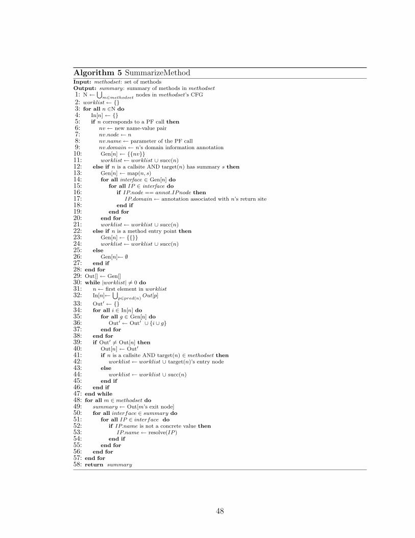
Algorithm 5 SummarizeMethodInput: methodset: set of methodsOutput: summary: summary of methods in methodset1: N ←
⋃m∈methodset
nodes in methodset’s CFG
2: worklist← {}3: for all n ∈N do4: In[n] ← {}5: if n corresponds to a PF call then6: nv ← new name-value pair7: nv.node← n8: nv.name← parameter of the PF call9: nv.domain← n’s domain information annotation10: Gen[n] ← {{nv}}11: worklist← worklist ∪ succ(n)12: else if n is a callsite AND target(n) has summary s then13: Gen[n] ← map(n, s)14: for all interface ∈ Gen[n] do15: for all IP ∈ interface do16: if IP.node == annot.IPnode then17: IP.domain← annotation associated with n’s return site18: end if19: end for20: end for21: worklist← worklist ∪ succ(n)22: else if n is a method entry point then23: Gen[n]← {{}}24: worklist← worklist ∪ succ(n)25: else26: Gen[n]← ∅27: end if28: end for29: Out[] ← Gen[]30: while |worklist| 6= 0 do31: n← first element in worklist32: In[n]←
⋃p∈pred(n)
Out[p]
33: Out′ ← {}34: for all i ∈ In[n] do35: for all g ∈ Gen[n] do36: Out′ ← Out′ ∪ {i ∪ g}37: end for38: end for39: if Out′ 6= Out[n] then40: Out[n] ← Out′
41: if n is a callsite AND target(n) ∈ methodset then42: worklist← worklist ∪ target(n)’s entry node43: else44: worklist← worklist ∪ succ(n)45: end if46: end if47: end while48: for all m ∈ methodset do49: summary ← Out[m’s exit node]50: for all interface ∈ summary do51: for all IP ∈ interface do52: if IP.name is not a concrete value then53: IP.name← resolve(IP )54: end if55: end for56: end for57: end for58: return summary
48
a set of methods. The input to SummarizeMethod is methodset, which contains a
set of methods to analyze. The output of SummarizeMethod is the summary of the
methods in methodset. The summary is a set of sets of name-value pairs that are
accessed along paths of execution in methodset. In some cases, the name of a pair
is not defined within the method scope. For example, the name could be provided
by one of the formal parameters to the method. In these situations, a placeholder is
used instead of a name-value pair. When the summary of the method is evaluated
within a calling context that allows resolution of the name of the name-value pair, the
placeholder is replaced by the resolved value for that evaluation. Using the previous
example, the placeholder would be resolved at call sites where the formal parameter
can be matched with an actual parameter.
In the explanation of SummarizeMethod, I assume the availability of the following
functions: target(n), which returns the set of methods that could be called at a call
site n; succ(n), which returns all successors of n in n’s control-flow graph (CFG); and
pred(n), which returns all predecessors of n in n’s CFG.
SummarizeMethod first initializes the data structures used in the rest of the al-
gorithm. Set N is initialized with all of the nodes in all of the methods in methodset
(line 1) and worklist is initialized to the empty set (line 2). For each node n, its Gen
set is initialized in one of four ways (lines 3–28):
1. If n represents a PF call, a new name-value pair nv that corresponds to the
parameter accessed at node n is created (line 6). The fields of nv are initialized
with the information at n: node ID (line 7), variable that contains the name of
the name-value pair (line 8), and domain information computed during the first
phase (line 9). Then the Gen set for n is initialized (line 10), and all successors
of n are added to the worklist (line 11).
2. If n is a callsite and the target of the call is a summarized method with summary
49

s, n’s Gen set is initialized with the value returned by function map invoked on
n and s (line 13). The map function takes a method m’s summary and a callsite
invoking m and replaces each placeholder with the corresponding argument at
the callsite. Then, for each entity in each interface contained in n’s Gen set
(lines 14 and 15), SummarizeMethod checks whether the annotations created
by Phase 1 for n’s return site apply to any of the entities; that is, whether they
refer to the same IP node (line 16). If so, it updates the domain information for
the entity using the domain information in the relevant annotations (line 17).
After performing this operation, SummarizeMethod adds n’s successors to the
worklist (line 21).
3. If n is a method entry point, its Gen set is initialized to a set containing an
empty set (line 23), and n’s successors are added to the worklist (line 24).
4. Finally, if n is not a callsite, SummarizeMethod initializes n’s Gen set to the
empty set (line 26).
After initializing the data structures, SummarizeMethod enters its iterative part,
where it processes nodes until the worklist is empty (lines 30–47). For each node n in
the worklist, SummarizeMethod computes the value of n’s In set as the union of the
Out sets of n’s predecessors (line 32). Then SummarizeMethod computes Out′ as the
product of n’s In and Gen sets; for each interface (i.e., set of name-value pairs) i in
In and each interface g in Gen, SummarizeMethod generates an interface that is the
union of i and g and adds it to Out′ (line 34–36). If Out′ is different than Out[n] from
the previous iteration over n (line 39), SummarizeMethod updates Out[n] (line 40)
and updates the worklist as follows. If n is a callsite and its target method m is one
of the methods in the input set (i.e., m is in the same strongly connected component
of the CG as the current method), SummarizeMethod adds m’s entry node to the
50

worklist (line 42).2 Otherwise, SummarizeMethod simply adds n’s successors to the
worklist (line 44). Note that, if n is a callsite but its target method m is not in the
input set, m’s return site would be added to the worklist.
When the worklist is empty, SummarizeMethod performs the following operations
for each method m in the input set. First, at line 49 it identifies the set of interfaces
in the Out set of m’s exit node. Then for each name-value pair of each interface (lines
50 and 51), SummarizeMethod calls resolve, at lines 52–54, for any name that is not
a concrete value (i.e., defined using a variable). Finally, at line 58, SummarizeMethod
returns the summary associated with methodset. Note that all methods in methodset
have the same summary.
The purpose of function resolve is to identify the names of each name-value pair.
As input, resolve takes a string variable or a placeholder and attempts to find one
or more statements in the current method where the variable is initialized. To do
this, resolve starts at the variable’s point of use and follows use-definition chains
backwards within the method’s scope until it reaches a definition involving (1) a string
constant, (2) an expression, or (3) a method parameter. In the first case, resolve
returns the identified string constant. In the second case, it computes a conservative
approximation of the values of the string expression using the Java string analysis
developed by Christensen, Møller, and Schwartzbach [20] and returns the resulting
set of strings. Finally, in the third case, resolve identifies the formal parameter and
returns a placeholder that maps to that formal parameter.
The runtime complexity of the resolve function varies depending on the type
of string value to be analyzed. For the first case described above, the cost is O(1),
since resolving a string constant is simply a table lookup operation. The third case
is similarly trivial. In the worst case the exploration of the sequence of definitions
2By doing so, SummarizeMethod treats nodes in a set of strongly connected methods as a singlesuper-method, as described earlier.
51

and uses covers every node in the method, which can be bounded by O(n), where
n is the number of nodes in the CFG. The second case has the highest worse case.
Extracting the automaton that represents the possible values of a string expression
can be doubly exponential (i.e., O(abn)) [20]. Although, in most cases, the actual
runtime is O(n) since most string expressions are simple linear concatenations of
string constants. The worst case corresponds to a program that modifies the string
expression and branches in every statement. An implementation optimization is to
precompute the string values that correspond to each string variable. At runtime,
each string resolution then becomes an O(1) operation. In my implementation this
optimization was not needed, and all of the runtime measurements of the analysis
include the string resolution.
Illustration with Example Web Application
To illustrate the second phase, I illustrate ExtractInterfaces using QuoteCon-
troller. There are two inputs to ExtractInterfaces: 1) the ICFG that was annotated
by GetDomainInfo, and 2) the call graph for QuoteController. The annotated ICFG
is shown in Figure 14. Each node in the ICFG is numbered based on the source code
line number it represents. To distinguish lines of the algorithm and ICFG, I number
each line n in the algorithm as An and each node n of the ICFG as Nn.
ExtractInterfaces begins by analyzing the call graph of QuoteController. There are
no non-trivial strongly connected components in this call graph, so SCC contains three
sets, one for each method of QuoteController. These are, in reverse topological order:
{saveQuoteDetails}, {getNumIP}, {service}. (Since method saveQuoteDetails
is stubbed in the example, I will skip over it.) The first method to be processed is
getNumIP, and SummarizeMethod is called as follows:
SummarizeMethod({getNumIP})
The first action of SummarizeMethod is to initialize the Gen set for each of the nodes
52

in getNumIP, which are {N48, N49, N50}. Node N48 corresponds to a PF call, so its
Gen set is initialized to {{N48}}, the domain information from the ICFG is copied,
and node N49 is added to the worklist. Node N49 and N50 are not PFs, callsites, or
method entry points, so their Gen sets are initialized to ∅. For all three nodes, their
Out sets are set equal to their Gen sets.
The iterative part of SummarizeMethod begins by iterating over the contents of
the worklist, which contains only node N49. In[N49] is set to the union of the out sets
of its predecessor. In this case, this is equal to Out[N48], which is {{N48}}. Similarly,
the Out′ value is also equal to {{N48}}. Out′ is different from the previous Out[N49],
so the Out set is updated. Node N49 is not a callsite, therefore the worklist is updated
with the successor of node N49, which is node N50. The next node in the worklist
is node N50. In[N50] is set to the union of the out sets of its predecessor. In this
case, this is equal to Out[N49], which is {{N48}}. Once again, the Out′ value is equal
to {{N48}}, which differs from the previous Out[N50], therefore Out[N50] is updated.
Node N50 is not a callsite and does not have any successors, so the worklist is now
empty.
SummarizeMethod then identifies the names in the interfaces of getNumIP. To do
this, SummarizeMethod iterates over each of the elements of the Out set of getNumIP’s
exit node, node N50. Out[N50] is {{N48}}. The resolve function follows the use-
definition chain of the variable name backwards through the method and identifies
that it was defined as one of the method’s formal parameters. The resolve function
returns a placeholder that denotes that the name is defined by the second formal
parameter to the method. The final summary for getNumIP is {{FP2}}.
The second method to be processed by SummarizeMethod is service. Nodes
N4, N7, N25, N26, and N29 contain calls to PFs, so their Gen sets are initialized to
{{N4}}, {{N7}}, {{N25}}, {{N26}}, and {{N29}}, respectively. Nodes N6, N27, and
N30 are callsites to getNumIP, which has a summary, so the map function substitutes
53

in the placeholder for the variable at each node that contains the second formal
parameter. The corresponding Gen sets are {{“age”}}, {{“age”}}, and {{“year”}}.
The remainder of the nodes are assigned a Gen set of ∅. Once again, the Out set of
each node is initialized to the node’s Gen set.
For the iterative part of SummarizeMethod, the worklist contains the successors
of the nodes that did not have empty Gen sets, {N5, N7, N8, N26, N27, N28, N30, N31}.
Analysis begins with node N5. In[N5] is equal to the Out set of its predecessor, node
N4. The new Out[N5] is {{N4}}, and its successors, nodes N6 and N24, are added
to the worklist. Node N6 is the next node to be processed and In[N6] is {{N4}}.
Out[N6] set is calculated to be {{N4, “age”}} and its successor, node N7, is added
to the worklist. Node N7 is the next node to be processed. Its In set is Out[N6].
The new Out[N7] is {{N4, “age,” N7}}, and its successors are added to the worklist.
Node N8 is the next node to be processed. In[N8] is equal to Out[N7]. Gen[N8] is
∅, so Out[N8] set is equal to In[N8]. Nonetheless, the new Out[N8] is different from
its previous value, so it is updated, and node N8’s successor, node N9, is added to
the worklist. Processing of nodes N9–N23 does not add any additional information,
therefore Out[N23] is equal to the union of Out[N8] and Out[N4], which is {{N4}, {N4,
“age,” N7}}.
SummarizeMethod continues processing at node N24. In[N24] is the union of the
Out set of its predecessors, nodes N4 and N23: {{N4}, {N4, “age,” N7}}. Node N24
does not add any information to the In set, therefore its Out set is equal to its In set,
and processing continues at node N25. Gen[N25] is non empty, so Out[N25] is {{N4,
N25}, {N4, “age,” N7, N25}}. Similarly, nodes N26 and N27 have non-empty Gen sets,
so Out[N27] is {{N4, N25, N26, N27}, {N4, “age,” N7, N25, N26, N27}}. Node N28
does not add any additional information, therefore processing continues at nodes N29
and N30, which both have non-empty Gen sets. Out[N30] is {{N4, N25, N26, “age,”
N29, “year”}, {N4, “age,” N7, N25, N26, “age,” N29, “year”}}. Nodes N31–N36 do not
54

Table 2: Data-flow based interface information for QuoteController.
# Sets in Root Method Summary Interface
1 {N4} {action}
2 {N4, N6, N7} {action, age, state}
3 {N4, N25, N26, N27} {action, name, state, age}
4 {N4, N6, N7, N25, N26, N27} {action, age, state, name}
5 {N4, N25, N26, N27 N29, N30} {action, name, state, age, type, year}
6 {N4, N6, N7, N25, N26, N27 N29, N30} {action, age, state, name, type, year}
add any additional information, so Out[N36] is equal to Out[N30]. Node N38 has an
empty Gen set, therefore Out[N38] is equal to that of node N28. At node N39, the Out
set is equal to the union of the two sets in Out[N36] and the two sets in Out[N38].
Similarly, Out[N40] is equal to the union of the two sets in Out[N23] and the four
sets in Out[N38]. Nodes N41–N43 do not add any information to the Out sets, so the
Out[N44] (the exit node of service) is equal to Out[N38].
Table 2 summarizes the interface information computed as a result of running the
data-flow based approach on the example servlet, QuoteController. In the second
column (Sets in Root Method Summary), the table shows each of the six sets in the
Out set of the exit node of QuoteController’s root method, which is N44 of method
service. The third column (Interface) shows the set of names computed by running
resolve on each of the sets in the second column. Note that nodes N6, N27, and
N30, have the second argument at each callsite substituted for the placeholder in
GetNumIP’s summary.
55
5.1.2 Implementation
I developed a prototype tool, wam-df, that implements my approach for web appli-
cations developed using the JEE framework.3 As input, wam-df takes the set of Java
classes in a web application. For each servlet in the application, wam-df analyzes
its bytecode and outputs a list of the servlet’s interfaces. To generate call-graphs,
CFGs, and ICFGs, wam-df uses the soot program analysis framework.4 For re-
solving points-to information, Soot uses an implementation of the Class Hierarchy
Analysis (CHA) [22], and to compute data-dependency information, wam-df lever-
ages indus,5 a data analysis library built on top of soot. Lastly, the resolve function
that is used in Phases 1 and 2 uses the Java String Analysis (JSA) library [20] to
compute a conservative approximation of the different values a string can assume at
a given point in a program.
5.2 Symbolic Execution Based Interface Analysis
This section describes my second technique for identifying interfaces of a web applica-
tion. The primary goal of this approach is to improve the precision of the identification
of the interfaces and the interface domain constraints. To accomplish this, this tech-
nique performs a symbolic execution of a web application. The technique represents
certain types of input data to a web application as symbolic values and models in-
terface related operations during symbolic execution. The technique then uses the
results of the symbolic execution to identify the interfaces of the web application.
3http://java.sun.com/javaee/4http://www.sable.mcgill.ca/soot/5http://indus.projects.cis.ksu.edu/
56
5.2.1 Approach
My symbolic execution based approach for identifying the interfaces of a web appli-
cation can be broken down into three main steps. The first step performs a transfor-
mation of the web application so that name-value pairs are represented as symbolic
values and domain-constraining operations are modeled by symbolic operations. This
is done by performing a type-dependence analysis [5] on the web application to deter-
mine which operations need to be transformed. The second step symbolically executes
the web application and generates the path conditions (PCs) and symbolic state (SS)
for each component. The third step identifies the accepted interfaces and interface
domain constraints of the web application by analyzing the PCs and SSs generated
during symbolic execution.
All three steps of the algorithm are shown in Algorithm 6. Lines 1–13 show the
first step (Section 5.2.1.1), line 14 is the second step (Section 5.2.1.2), and the third
step (Section 5.2.1.3) is shown in lines 15–24. In the following sections, I explain each
of the three steps in more detail.
5.2.1.1 Step 1: Symbolic Transformation
In the first step, the approach transforms the web application so that its symbolic
execution will provide information about accepted interfaces and interface domain
constraints. Step 1 is shown in lines 1–13 of Algorithm 6. There are two parts to this
transformation. The first is to identify points in the application where symbolic val-
ues must be introduced to precisely model the application’s name-value pairs. This
is done by replacing each call to a PF with a customized version that initializes
and returns a symbolic value (lines 1–3). The second part is to identify and replace
domain-constraining operations with special symbolic operators that will appropri-
ately update the PC and SS as the application is symbolically executed. This is done
by using type-dependence analysis [5] to identify operations that need to be replaced
57
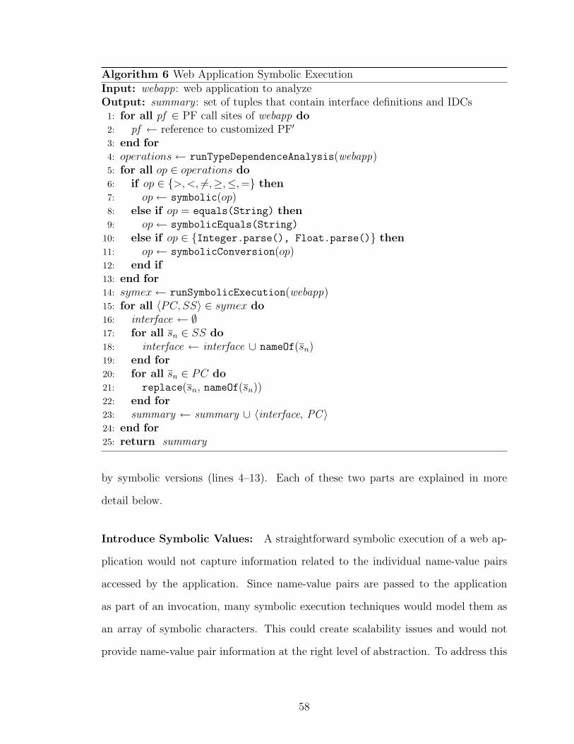
Algorithm 6 Web Application Symbolic Execution
Input: webapp: web application to analyzeOutput: summary : set of tuples that contain interface definitions and IDCs
1: for all pf ∈ PF call sites of webapp do2: pf ← reference to customized PF′
3: end for4: operations← runTypeDependenceAnalysis(webapp)5: for all op ∈ operations do6: if op ∈ {>, <, 6=,≥,≤, =} then7: op← symbolic(op)8: else if op = equals(String) then9: op← symbolicEquals(String)
10: else if op ∈ {Integer.parse(), Float.parse()} then11: op← symbolicConversion(op)12: end if13: end for14: symex← runSymbolicExecution(webapp)15: for all 〈PC, SS〉 ∈ symex do16: interface ← ∅17: for all sn ∈ SS do18: interface ← interface ∪ nameOf(sn)19: end for20: for all sn ∈ PC do21: replace(sn, nameOf(sn))22: end for23: summary ← summary ∪ 〈interface, PC 〉24: end for25: return summary
by symbolic versions (lines 4–13). Each of these two parts are explained in more
detail below.
Introduce Symbolic Values: A straightforward symbolic execution of a web ap-
plication would not capture information related to the individual name-value pairs
accessed by the application. Since name-value pairs are passed to the application
as part of an invocation, many symbolic execution techniques would model them as
an array of symbolic characters. This could create scalability issues and would not
provide name-value pair information at the right level of abstraction. To address this
58

issue, the approach models each individual name-value pair as a symbolic value.
My approach replaces each PF with a customized version so that when the appli-
cation accesses a name-value pair, it returns a reference to a symbolic string instead
of a normal string object. The length of the value of this symbolic string is bounded
so that comparisons of its value and looping constructs over its characters are not in-
finite. The bound for this value was determined empirically by examining the subject
web applications and using the length of the longest string constant compared against.
The only imprecision introduced by this bound is that any values compared against
that are larger than the bound will not be accurately modeled by the approach. Al-
though this value was determined manually for my approach, its determination could
be automated via static analysis of the code.
Each symbolic string returned by a PF is uniquely identified by the name of the
name-value pair that was passed as an argument to the PF. This name is always
known at the time of execution, unless the name itself is also a symbolic string or it is
defined externally (e.g., in a resource file). In this case, it is not possible to determine
the name of the name-value pair, and the approach adds a constraint to the PC that
specifies that the name-value pair’s name is equal to the value of another name-value
pair or is defined externally. If a specific name-value pair is accessed more than once
along a path, a reference to the previously returned symbolic string is returned. This
is consistent with the normal behavior of the PFs, which return the same value when
called with the same name-value pair name.
Identify and Replace Domain-Constraining Operations: To accurately cap-
ture the constraints placed on name-value pair values during the symbolic execution,
the approach replaces domain-constraining operations with specialized symbolic ver-
sions. These specialized versions provide special handling for the symbolic name-value
59

pairs in addition to the normal semantics of the operation. The special handling up-
dates the PC and SS to reflect the domain constraints the operations place on the
symbolic name-value pairs.
The type of operations replaced during the transformation can vary according to
the programming language and framework utilized in the web application implemen-
tation. In general, the following type of operation are replaced with symbolic versions:
(1) string comparators, (2) functions that convert a string to an integer or float, and
(3) arithmetic comparison operations: >, <, 6=, ≥, ≤, and =. In Section 5.2.1.2, I
formally define the symbolic semantics of each of these domain-constraining opera-
tions. If a specific language or framework provides additional domain-constraining
operations, the implementation of this approach can take advantage of the additional
semantics of these operation to provide even more precise domain information.
My approach uses type-dependence analysis to identify specific instances of domain-
constraining operations in the web application that need to be replaced. Type de-
pendence analysis is a static analysis that identifies the flow of symbolic values in
software that is being transformed for symbolic execution [5]. The use of type de-
pendence analysis allows my approach to precisely replace only those operations that
could actually operate on symbolic values at runtime. By introducing symbolic oper-
ations only for instances that have a symbolic value flow to them, the overall runtime
of the analysis is reduced by avoiding unnecessary and expensive symbolic operations.
5.2.1.2 Step 2: Generating Path Conditions
In the second step, the approach generates a set of tuples of the form 〈PC, SS〉
by symbolically executing the transformed web application. Step 2 corresponds to
line 14 of Algorithm 6. For each tuple generated in this step, PC represents a family
of paths from the entry to the exit of one of the application’s web components and
SS represents the corresponding symbolic state of the web application. The symbolic
60

Table 3: Path condition and symbolic state before/after execution of symbolic oper-ations.
(PC, state)–Before Operation (PC, state)–After
(C, SS) s = getIP(name) (C, SS[s ↪→ sname])
(C, SS[s ↪→ sname]) v = Integer.parse(s) (C ∧ type(sname) = int, SS[s ↪→ sname, v ↪→ vname])
(C, SS[s ↪→ sname]) v = Float.parse(s) (C ∧ type(sname) = float, SS[s ↪→ sname])
(C, SS[s ↪→ sn, t ↪→ tm]) if(s.equals(t)){} (C ∧ sn = tm, SS[s ↪→ sn, t ↪→ tm])else{} (C ∧ sn 6= tm, SS[s ↪→ sn, t ↪→ tm])
(C, SS[v ↪→ vn, w ↪→ wm]) if(v ⊗ w)){} (C ∧ vn ⊗ wm, SS[v ↪→ vn, w ↪→ wm])else{} (C ∧ ¬(vn ⊗ wm), SS[v ↪→ vn, w ↪→ wm])
execution generates these tuples by collecting constraints on the symbolic values dur-
ing execution of the component and tracking the creation of symbolic variables in
the web application. These constraints and variables are created by the operations
introduced in the first step.
To explain the details of the symbolic execution, I use the table in Figure 3. This
table formally defines the effect of different program statements on the PC and SS.
The PC is shown as a conjunction of constraints, and the SS is represented by a
valuation function SS that maps each variable in the program to its corresponding
value in the state. For example, SS[x ↪→ v] specifies that, in the symbolic state,
variable x is mapped to the symbolic value v. Symbolic values are shown with an
overline notation. Subscripts on symbolic values are used to show the name of the
name-value pair that is represented by the symbolic value. For example, saction shows
a symbolic value s that is associated with the name-value pair named “action.” In
the table, the left-hand column shows the PC and relevant parts of SS before the
operation, the middle column shows the operation, and the right-hand column shows
the PC and the relevant parts of SS after the operation.
Accessing the Name-value Pair: The symbolic execution of a PF (i.e., s =
getIP(name)) creates a symbolic string sname and assigns it to s. The access creates
61

a one-to-one mapping in SS between the name-value pair name and the symbolic
string. In the example servlet, a name-value pair is accessed at lines 1, 3, 5, 22, 23,
and 43. The execution of these lines updates the symbolic state of the program with
new symbolic strings. For example, line 4 of QuoteController (Figure 12) creates the
symbolic string saction and maps it to the variable actionValue.
Conversion to Numeric Type: When a statement of type i = Integer.parse(s)
is executed, and the value of s is a symbolic string sname, the technique updates SS
and the PC. The constraint type(sname) = int is added to the PC to record the fact
that, on the current path, the symbolic string sname is converted to an integer value.
The approach updates SS by adding a new symbolic integer vname that represents the
numeric value of the symbolic string. (In the table, the relation between the symbolic
string and symbolic integer is shown by using the same name in the subscript.) A
symbolic string can also be converted to other types, such as float. These types are
handled similarly to the case of int. A one-to-one mapping between a symbolic string
and its corresponding symbolic numeric value is maintained via the name attribute.
As a consequence, if a symbolic string is converted to a numeric value multiple times
on a path, only one symbolic value is created during the first conversion and then
reused for subsequent accesses.
In the example, every name-value pair that is accessed via getNumIP is converted
to an int by the call to Integer.parse() at line 49. For example, the call to
getNumIP at line 6 modifies the PC by adding the constraint type(sage) = int and
adds a mapping ageValue ↪→ vage to SS.
String Comparison: When a branch condition uses a symbolic string in a string
equality operation (e.g., s.equals(t)), the approach determines whether the con-
straints in the PC are sufficient to evaluate the condition. If the constraints are
62

sufficient, the approach can determine which branch to follow. Otherwise, the sym-
bolic execution follows both branches. Along the true branch, the approach conjoins
the PC with the branch condition; along the false branch, it conjoins the PC with
the negation of the branch condition.
To illustrate with an example, consider the comparison of saction at line 5. When
this comparison is evaluated, saction is not a concrete value, and the correct branch to
follow cannot be determined. Therefore, the symbolic execution follows both branches
and creates two PCs, one with the constraint saction = “CheckEligibility”, and the
other with saction 6= “CheckEligibility”. Along one of the paths reaching line 24, saction
is equal to “CheckEligibility”, so the constraint solver can evaluate this comparison
and determine that saction cannot also be equal to “QuoteInformation”. Along another
path reaching line 24, saction is not equal to “CheckEligibility”. Therefore, saction may
or may not be equal to “QuoteInformation” and, once again, two PCs are generated,
one for each branch.
Arithmetic Constraints: If an arithmetic expression of the form i⊗j is evaluated
in a predicate and one of the operands is a symbolic numeric value, the approach adds
the arithmetic constraint to the PC. Operator⊗ can be one of the following arithmetic
comparison operators: >, <, 6=, ≥, ≤, and =.
In the example servlet, an arithmetic comparison on a symbolic value occurs at
line 14. Since the value of vage cannot be determined, the result of the evaluation of
this statement is two PCs, one with the constraint as true (vage < 16) and the other
one with the constraint as false (vage ≥ 16).
5.2.1.3 Step 3: Interface Identification
In the third step, my approach identifies accepted interfaces and IDCs by analyzing
the set of tuples generated in the second step. Step 3 is shown in lines 15–24 of
Algorithm 6. The first part of Step 3 is to identify the names that define the accepted
63

interface referenced by each tuple. The intuition for this part is that each name-
value pair accessed along a path is added to SS; therefore, the unique collection of
names associated with symbolic strings in SS corresponds to the names that define an
accepted interface of the component. Lines 16–19 of Algorithm 6 compute these names
by iterating over each symbolic string (sn) in SS, identifying the name associated
with the symbolic string, and adding it to interface. The second part of Step 3 is
to identify the IDC associated with the interface. This is simply the PC with the
names of the symbolic variables rewritten to match the naming of the parameters
in interface. Lines 20–22 of Algorithm 6 perform this rewrite by iterating over each
symbolic string (sn) in the PC and replacing the reference to the symbolic string with
the name associated with the symbolic string.
SS[actionValue ↪→ saction, ageValue ↪→ sage, stateValue ↪→ sstate]
Figure 15: Symbolic state for paths that take branch 5T of QuoteController.
To illustrate with an example, consider the PC and SS of the family of paths that
take the true branch at line 5 of QuoteController (shown in Figure 12). As described
in Section 5.2.1.2, lines 4, 6, and 7 contain statements that create symbolic strings.
The relevant part of the symbolic state for this family of paths is shown in Figure 15.
Iterating over each of the symbolic strings in SS leads to the identification of action,
age, state as the parameter names that define the accepted interface.
1. saction = “CheckEligibility” ∧ type(sage) = int ∧ sage ≥ 16 ∧ sstate = “GA”
2. saction = “CheckEligibility” ∧ type(sage) = int ∧ sage < 16 ∧ sstate = “GA”
3. saction = “CheckEligibility” ∧ type(sage) = int ∧ sage ≥ 16 ∧ sstate 6= “GA”
4. saction = “CheckEligibility” ∧ type(sage) = int ∧ sage < 16 ∧ sstate 6= “GA”
Figure 16: Path conditions for paths that take branch 5T of QuoteController.
Figure 16 shows the path conditions for paths that take the true branch at line 5
of QuoteController. By iterating over each of the symbolic strings in each of the four
64

path conditions and performing the rewrite of their name, the four interface domain
constraints shown in Figure 17 are generated.
1. action = “CheckEligibility” ∧ type(age) = int ∧ age ≥ 16 ∧ state = “GA”
2. action = “CheckEligibility” ∧ type(age) = int ∧ age < 16 ∧ state = “GA”
3. action = “CheckEligibility” ∧ type(age) = int ∧ age ≥ 16 ∧ state 6= “GA”
4. action = “CheckEligibility” ∧ type(age) = int ∧ age < 16 ∧ state 6= “GA”
Figure 17: IDCs for the paths that take branch 5T of QuoteController.
5.2.2 Implementation
I developed a prototype tool called wam-se (Web Application Modeling with Sym-
bolic Execution) that implements my symbolic execution based approach. wam-se is
written in Java and implements the approach for web applications written in the Java
Enterprise Edition (JEE) framework. The implementation consists of three modules,
transform, se engine, and pc analysis, which correspond to the three steps of
the approach.
The transform module implements the symbolic transformation described in Sec-
tion 5.2.1.1. The input to this module is the bytecode of the web application and
the specification of program entities to be considered symbolic (in this case, sym-
bolic strings). The module transforms the application to introduce symbolic values
and replaces domain-constraining operations with their special symbolic counterparts.
The output of the module is the transformed web application, which is ready to be
symbolically executed in Step 2.
To perform the transformation, I use Stinger, a previously developed technique
and tool [6]. Stinger identifies points in an application where symbolic values are
introduced. It then analyzes the code to determine which operations and types in the
code may interact with the symbolic values and transforms them into their symbolic
65

counterparts. A benefit of using Stinger is that it allows the approach to only translate
types and operations that should be symbolic and avoid the unnecessary overhead
that would be introduced by transforming the entire application.
To specify the program entities to be considered symbolic, I built a customized
version of the JEE libraries. This version creates a new symbolic string for a name-
value pair when a PF function in the JEE library is symbolically executed. I made
two main customizations: (1) the definition and implementation of a symbolic string
class for Java, and (2) the rewrite and modification of all PFs so that they return a
symbolic representation of each accessed name-value pair. The symbolic string is im-
plemented as an extension to the normal Java String class with overridden member
functions to account for the different semantics of a symbolic string. Currently, the
only string operator modeled by my implementation is string equality, which includes
equality between two symbolic strings, two constant strings, or a constant string and
a symbolic string. Constraints involving more complex operations, such as matching
of regular expressions, are not handled by the symbolic execution and undelrying
constraint solver. Extending the technique to model these types of constraints using
specializing string constraint solvers, such as HAMPI [46], would increase the pre-
cision of the IDCs, but would also increase the cost of the constraint solving. My
examination of subject applications suggests that the increase in code coverage would
be minimal with this extension.
The modified PFs, when accessed, create a symbolic string, associate the name
of the accessed name-value pair with the symbolic string, and maintain a map of
names to symbolic values to ensure that the same symbolic value is returned when a
name-value pair name is accessed multiple times. Along with these customizations, I
also implemented symbolic versions of the numeric conversion functions. No further
implementation was necessary to handle arithmetic operations, as symbolic versions
of these operations are provided by the underlying symbolic execution engine.
66

Stinger also identifies two types of situations in the code that might cause problems
for the symbolic execution: (1) constraints that cannot be handled by the underlying
decision procedure, and (2) symbolic values that may flow outside the scope of the
symbolically executed code (e.g., to native code). For the first situation, a limitation
of the underlying decision procedure that I used was that it could not handle symbolic
floating point values. When Stinger detected floating point values and operations
that needed to be replaced, I rewrote the code in the applications so that the same
operations were expressed in terms of integer values. This occurred in several of the
applications I used for my evaluation and involved rewriting predicates of the form
“value⊗X.0” to “value⊗X,” where ⊗ is any of the arithmetic operators and X is
some integer value. In several of the subject applications, the use of floating point
values was integral to the correct semantics of the application and was extensive
throughout the application. This prevented me from easily making similar changes
and meant that it was not possible to run the symbolic execution based approach
on these applications. There were no other types of constraints present in the web
applications that could not be handled by the decision procedure. Almost all of
the constraints that did involve symbolic name-value pair values were fairly small
(2 – 4 conditions) and typically only involved numeric equality, string equality, or a
numeric conversion. For the second potentially problematic situation, I found that
although there was extensive use of external libraries in the subject applications, for
the most part, none of the symbolic values flowed into these libraries. For two of
the applications, however, the symbolic values were passed to external libraries that
could not be transformed and it was not possible to run the symbolic execution based
approach on these applications.
The se engine module implements the symbolic execution described in Sec-
tion 5.2.1.2. The input to this module is the bytecode of the transformed web ap-
plication, and the output is the set of all PCs and corresponding symbolic states for
67

each component in the application. To implement the symbolic execution, wam-se
leverages a symbolic execution engine [45] built on top of Java Path Finder (JPF) [91]
and the YICES6 constraint solver. JPF is an explicit-state model checker for Java
programs that supports all features of Java. JPF explores all program paths systemat-
ically, when it reaches the end of the program it backtracks to every non-deterministic
branch on the path and explores other paths from that branch. This process continues
until every path in the program has been explored. The symbolic execution engine
handles recursive data structures, arrays, numeric data, and concurrency. If the sat-
isfiability of the path condition cannot be determined, as the problem of checking
satisfiability is undecidable in general, JPF assumes that both branches are feasible.
This is a safe way to handle the situation, but can reduce the precision of the analysis.
The pc analysis module implements the analysis described in Section 5.2.1.3. The
input to this module is the set of PCs and SSs for each component in the application,
and the output is the set of IDCs and accepted interfaces. The module iterates over
every PC and SS, identifies the accepted interfaces, and associates the constraints on
each name-value pair with its corresponding accepted interface.
5.3 Comparison of Interface Analysis Approaches
The two approaches to interface analysis each have benefits and drawbacks to their
usage. In this section, I contrast the two approaches and discuss their benefits and
drawbacks in terms of their usefulness and applicability.
The first technique for interface identification is based on iterative data flow analy-
sis. The primary benefit of this technique is that it can be used to analyze almost any
web application. To use the technique, the basic requirement is that the web applica-
tion must use a framework that provides an identifiable PF for accessing name-value
pairs. Since almost all frameworks define a set of PFs, in practice, this technique is
6http://yices.csl.sri.com/
68

widely applicable. However, there are two issues that can affect the usefulness of the
information generated by the approach:
1. The technique computes a conservative over-approximation of the interfaces of a
web application. The underlying cause of this over approximation is infeasible
paths. The technique propagates data-flow information over all paths in the
control flow graph, regardless of whether the paths are feasible. This means
that if there are infeasible paths in the code of the web application and interface
elements are accessed along parts of those paths, the results of the analysis
could contain infeasible interfaces. As the empirical results presented later in
the dissertation show, for some types of quality assurance techniques, the over
approximation of the interfaces can lead to: (1) inefficiencies when the infeasible
interface information causes extra test cases to be generated or analysis to
be performed, and (2) incorrect results in quality assurance techniques that
assume the interface identification is precise. These problems are particularly
pronounced for applications with a high number of infeasible paths.
2. The domain information identified by the data flow based technique is associated
on a per-PF-callsite basis. This type of association means that all name-value
pairs accessed through the same PF are assigned the same domain information.
The reason this occurs is that the computation of the domain information fol-
lows all sequences of definitions and uses originating from the PF call and does
not distinguish the domain information on a per-path basis. Although copying
annotation summary information provides context sensitivity to the domain in-
formation, the net effect is still that a name-value pair can be assigned overly
conservative domain information. Case in point, for QuoteController in Fig-
ure 12, the name-value pair named action is assigned the relevant values of
69

“checkeligibility” and “register.” Although this is a safe approximation, cor-
relating the domain information with a specific path would be more precise.
This issue can also lead to inefficiencies and incorrect results for certain qual-
ity assurance techniques. This effect is higher for applications whose interface
domain constraints vary significantly along different paths.
My second approach for interface identification, which is based on symbolic execu-
tion, is designed to address the limitations in precision introduced by infeasible paths.
The use of symbolic execution allows the second approach to identify some infeasible
paths and, consequently, not calculate interface information along those paths. It also
allows the approach to associate domain information on a per path basis as opposed
to associating it with a specific PF callsite. However, there are several issues that
may arise that can prevent the symbolic execution based approach from being applied
as easily as the data-flow based approach:
1. For some web applications, it might not be possible to perform the symbolic
transformation step. Although in most cases the transformation can be done au-
tomatically, certain cases can prevent it from completing successfully. Namely,
these cases are when symbolic values flow to external libraries or are used in
constraints that can’t be handled by the underlying constraint solver. (See Sec-
tion 5.2.1.1) If the analysis identifies these special cases, developer intervention
is required. The intervention could range from a simple change in the code to
the development of stubbed symbolic methods, which might be time consuming
and error prone for developers.
2. Path conditions whose truth value cannot be determined by the constraint
solver. In these cases, my approach treats both paths as if they were feasible.
Although this is safe, it can introduce imprecision into the results. However,
70

Table 4: Comparison of interface analysis statistics.
SubjectInterfaces Domain Constraints Time (s)DF SE DF SE DF SE
Bookstore 338 70 527,517 10,611 2,322 1,479
Checkers 37 - 44 - 160 -
Classifieds 222 41 92,470 3,954 1,797 766
Daffodil 101 - 1012 - 1,271 -
Employee Directory 88 18 1,426,884 3,764 741 905
Events 118 25 74,809 1,724 333 586
Filelister 31 - 32 - 248 -
Office Talk 54 - 80 - 207 -
Portal 322 51 29,444,929 11,217 988 1,528
unless all paths with interface information contain branch conditions that can-
not be satisfied, this approach is still more precise than the data-flow based
approach. In the worst case, this approach would be no less precise than the
data-flow based approach.
3. Large web applications can cause scalability problems. Although, most web ap-
plications are highly modular, with each module well within the size that most
modern symbolic engines can handle efficiently, applications could have unusu-
ally large modules, which could cause the symbolic execution based approach to
take significantly longer. It is possible that this increase in analysis time would
make the technique impractical for these applications.
For the purpose of quantitatively comparing the two interface analysis approaches,
I ran both on the subject applications introduced in Chapter 3. Table 4 shows a sum-
mary of the interface information identified by the data-flow (DF ) and symbolic exe-
cution (SE ) based approaches. The table shows comparisons based on the number of
71

interfaces discovered by each approach(Interfaces), the number of domain constraints
(Domain Constraints) identified for the interfaces, and the analysis time in seconds
(Time (s)) for each application. It was not possible to analyze four applications us-
ing the symbolic execution based approach. These applications either had symbolic
values that flowed to external libraries that could not be modified or the applications
placed constraints on the symbolic values that could not be handled by the YICES
constraint solver. The corresponding data points for these applications are shown as
a dash (-) symbol. The results in the table indicate three noteworthy observations.
1. The symbolic execution based approach discovers fewer interfaces than the data-
flow based approach. Although the discovery of more interfaces is generally good
for quality assurance purposes, in this case the data-flow based technique’s num-
ber reflects the presence of spurious interfaces. I determined this by inspecting
the interfaces reported by both approaches for one of the subjects, Bookstore.
For this subject, the difference of the two sets was comprised exclusively of in-
terfaces that corresponded to infeasible paths. The specific effect of the spurious
interface information varies by its application. However, in general spurious in-
terfaces can result in inefficiencies for quality assurance techniques that perform
analysis on each discovered interface.
2. The number of IDCs is substantially lower for the symbolic execution approach.
This is significant because quality assurance techniques, such as test-input gen-
eration, directly use the IDCs to generate test cases. If a significant number
of these IDCs relate to infeasible paths, then a significant number of the test-
inputs are not likely to add additional coverage or fault detection ability to
their test suites. This difference in the number of IDCs also reflects the effect
of path-sensitive domain information. Since the data-flow based approach does
72

not track domain information in a path-sensitive manner, the number of possi-
ble IDCs is actually the Cartesian product of every possible domain constraint
on each parameter in an interface. As can be seen in the table, this number can
grow to be very large.
3. The analysis time for the symbolic execution based approach is comparable in
analysis time to the data-flow based approach. This seems counter-intuitive
since symbolic execution is a notoriously expensive analysis; however, there are
several factors that contribute to this result. First, the subject applications
contain a high number of infeasible paths, which indicates the possibility that
the time to propagate data-flow information along the extra infeasible paths is
higher than the cost of the constraint solving that determines the path is in-
feasible. Second, as compared to typical symbolic execution, my approach only
symbolically models the name-value pairs, and there are not many constraints
that involve name-value pairs (2–4 per name-value pair in my subjects). This
means that the path conditions generated by the symbolic execution tend to be
relatively small and can be solved quickly by the constraint solver. Third, the
implementation of the data-flow based approach is a prototype, whereas Stinger
and JPF are more mature and have been optimized for performance. Fourth,
as compared to traditional software, web applications do not cause as many
scalability problems for symbolic execution. Web applications are highly mod-
ular, components can be analyzed independently to identify interfaces, and the
size of a typical component is generally no more than several thousand lines of
code, which can be handled efficiently by most modern symbolic execution im-
plementations. Lastly, my approach models the name-value pairs at the string
level, which reduces the total number of constraints that would otherwise be
generated by modeling the name-value pairs at the character level.
73

Both approaches to interface analysis identify the names of parameters that make
up an interface and domain information about those parameters. As the results
presented later in the dissertation will show, information from either approach is
useful for improving quality assurance techniques; however, each approach has its
own strengths. The approach based on data-flow analysis is widely applicable and
can be used for most all web applications. The symbolic execution based approach
can increase the precision of the interface information, but could potentially require
more developer intervention to run successfully.
74

CHAPTER VI
COMPONENT OUTPUT ANALYSIS
Accounting for the semantics of a component’s output is important for understand-
ing the overall behavior of a web application. Component output, which is trans-
mitted over Hyper Text Transfer Protocol (HTTP), generally comprises web pages
that contain Hyper-Text Markup Language (HTML), images, and client-side scripts.
Together, these elements create a generated object program that is then interpreted
and displayed by the end user’s client system (e.g., browser). By interacting with
these object programs, an end user can make requests to the application and, via
web forms, supply data for invocations. This gives the generated object programs
an important role in defining the overall functionality of a web application. Because
this role can often represent a considerable portion of the functionality of a web ap-
plication, it is important to include the generated object programs’ semantics when
considering the behavior of a web application.
Identifying the content and structure of a component’s generated object programs
is a challenging task. Part of the reason for this is that many modern web appli-
cations generate their content at runtime. This practice has the benefit of allowing
developers to generate customized content for end users, but it also complicates the
identification of the object programs because their content can vary significantly be-
tween executions. Although a careful manual inspection could identify the structure
and content of the generated programs, there are many characteristics of modern
web applications that preclude the widespread application of this technique. The
first characteristic is that component output is often generated using complex string
operations that combine data from multiple sources. This makes it complicated to
75

accurately identify the content that is outputted by a statement in a component.
The second characteristic is that the structure of the output can vary along different
control flow paths. This means that manual inspection must account for the differ-
ent ways that output-generating statements can combine their output along different
paths. The third challenge is one of scalability. A large component can have several
thousand lines of code, of which a significant majority can generate output or mod-
ify data that eventually becomes part of the component’s output. This means that
manual inspection must be able to track operations involving a large combination of
different output-generating statements. Taken together, these characteristics make it
difficult to identify object programs through manual inspection and suggest that the
use of automated analyses is more appropriate.
Despite the importance of identifying a component’s output, there has only been
sporadic attention devoted by the research community to this problem. Early tech-
niques relied on web crawling to identify an application’s web pages. These techniques
were sufficient for early web applications, whose content was composed primarily of
static HTML pages. However, they are generally incomplete for modern web ap-
plications that generate content dynamically. Other techniques attempt to address
this problem for web applications written in specialized language frameworks such as
<bigwig> [15]. The limitation of these types of approaches is that they are only appli-
cable for certain frameworks and generally do not translate well to web applications
written in more general purpose languages. One technique uses a context-free gram-
mar to estimate the possible HTML pages that could be generated by a component,
but the technique is not easily applied to a wide variety of web applications [58].
More recent work has utilized concolic execution to identify component output in
PHP-based web applications [10]. For applications that are analyzable using this ap-
proach, this is a very effective technique. However, typical problems associated with
concolic execution, such as path explosion and constraints that cannot be handled
76

by the underlying constraint solver, can limit the type of applications that can be
analyzed.
My analysis technique provides a way to conservatively identify the output of a web
component. The technique can handle dynamic generation of HTML content and can
be easily applied to a wide variety of web applications. The basic mechanism of the
technique is to perform an iterative data-flow analysis over the control-flow graph of
a web application and identify sets of statements that can generate HTML along each
path. These sets are then analyzed to identify their generated HTML output using
two specialized techniques: Fragment Filtering and HTML Fragment Resolution. An
additional feature of the technique is that it provides customization points, which
allows the analysis to be used to identify only certain HTML elements of interest.
For my dissertation work, I customize the analysis to allow for the identification of
links and web forms that could be part of a component’s HTML output.
The organization of the rest of this chapter is as follows: Section 6.1 describes the
various algorithms and supporting analyses that make up the Component Output
Analysis. The customizations to identify links and web forms are discussed in Sec-
tion 6.2. Both the main algorithms and the customizations are illustrated using the
example web application from Chapter 2. The implementation details are presented
in Section 6.3, and I discuss limitations of the analysis in Section 6.4.
6.1 Component Output Analysis Algorithms
The goal of the component output analysis is to compute the set of HTML pages that
can be generated by a component. To make the approach practical, the technique
relies on a worklist-based data-flow analysis and a modular analysis based on the use
of method summaries that represent the HTML fragments generated by the method.
The basic idea is to analyze each method, or group of strongly connected methods,
of the component. The strongly connected components that are greater than size
77

one represent methods that recursively call each other. Each of these is treated
as one “super-method” and its methods are analyzed together. The methods are
analyzed in reverse topological order with respect to the call graph to ensure that a
method’s summary is computed before its summary is needed. The use of method
summaries provides two benefits. They allow the technique to analyze each method
once and then use the method summary whenever the method is called again and
they provide context sensitivity to the analysis. Iterative data-flow analysis is used
within each method (or set of methods mutually involved in recursion) to compute
summary information [48]. The analysis also provides a “plug-in” point that allows it
to be customized to identify specific types of HTML elements. This “plug-in point”
is implemented via a process called Fragment Filtering. Aside from allowing for
customization of the analysis, Fragment Filtering also provides a way to reduce the
size of the method summaries since HTML fragments can be minimized to remove
content unrelated to the elements of interest. At the end of the analysis of a web
component, the summaries of its root methods represent a conservative approximation
of the pages that can be generated by the component (minus content removed by
Fragment Filtering). This set of pages is then analyzed by an HTML parser to
extract the elements of interest.
The runtime complexity and convergence of the Component Output Analysis are
similar to those of wam-df in Section 5.1.1, since both are based on iterative data-
flow analysis. The core of the Component Output Analysis is the iterative data-flow
analysis that summarizes each method of the web application. This analysis converges
for two reasons: (1) The value domain for the sets in the data flow equations is finite,
as it can only include those nodes that either directly or indirectly generate output
(which is at most the number of nodes n in the web application’s ICFG); and (2)
the transfer function is monotonic because no values are removed from the calculated
data-flow sets. The runtime complexity of this analysis is dependent on the number
78

Algorithm 7 ExtractPages
Input: CG: call graph of the web componentOutput: content: component’s generated content
1: SCC ← set of strongly connected methods in CG2: for all mset ∈ SCC, in reverse topological order do3: summary ← SummarizeMethod(mset)4: for all m ∈ mset do5: associate summary to method m6: end for7: end for8: pages← summaries of component’s root method9: content← extractContent(pages)
10: return content
of nested loops in the code [44]. The number of nested loops is, in the worst case,
equivalent to the number of nodes n in the web application’s ICFG. Additionally,
each nested loop could cause the analysis to iterate over each of the nodes in the
ICFG. Therefore, the runtime complexity is O(n2). I assume the nodes are processed
in reverse postorder.
One important additional cost not included in the this runtime complexity is the
cost of the HTML Fragment Resolution. The string analysis used by this analysis
can vary widely in its runtime cost. Section 6.1.2 explains the HTML Fragment
Resolution and its complexity in more detail.
In the following sections, I present the algorithms for computing a component’s
output in detail. The algorithms that are at the core of the technique are presented
in Sections 6.1.1, 6.1.2, and 6.1.3. Section 6.1.4 illustrates the algorithms using the
running example.
6.1.1 Main Algorithm
Algorithm 7 shows ExtractPages, which initializes the algorithm’s data structures
and calls SummarizeMethod for each method set in the current component. The
input to ExtractPages is the call graph (CG) of the component to be analyzed, and
79

Algorithm 8 SummarizeMethodInput: methodset: set of methodsOutput: summary: summary of methods in methodset1: N ←
⋃m∈methodset nodes in m’s CFG
2: worklist← {}3: for all n ∈N do4: if n is the method entry point then5: Gen[n] ← {{}}6: Out[n] ← Gen[n]7: worklist← worklist ∪ succ(n)8: else if n writes to the component’s output stream then9: Gen[n] ← {n}
10: else if n is a callsite AND target(n) has a summary then11: Gen[n] ← {n}12: else13: Gen[n] ← ∅14: end if15: end for16: while |worklist| 6= 0 do17: n← first element in worklist18: In[n]←
⋃p∈pred(n)Out[p]
19: Out′ ← {}20: for all i ∈ In[n] do21: Out′ ← Out′ ∪ {append(i, Gen[n])}22: end for23: if Out′ 6= Out[n] then24: Out[n] ← Out′
25: if n is a callsite AND target(n) ∈ methodset then26: worklist← worklist ∪ entry node of target(n)27: else28: worklist← worklist ∪ succ(n)29: end if30: end if31: end while32: summary ← {}33: for all m ∈ methodset do34: for all nodeset ∈ Out[m’s exit node] do35: htmlfragments← {}36: for all n ∈ nodeset do37: generatedstrings← resolve(n)38: htmlfragments← htmlfragments× generatedstrings39: htmlfragments← reduce(htmlfragments)40: end for41: summary ← summary ∪ htmlfragments42: end for43: end for44: return summary
80

the output is the output generated by the component. To begin the analysis, Ex-
tractPages identifies the sets of strongly connected components in the CG and assigns
them to SCC (line 1). All nodes in CG are in SCC as either a singleton set (i.e., a
strongly connected component of size one) or as a member of a set of methods that
make up a strongly connected component of size greater than one. ExtractPages then
calls SummarizeMethod for each method set in SCC in reverse topological order with
respect to the call graph (lines 2–7). Reverse topological ordering ensures that each
method set is summarized before any method calls it. Each method in the method
set is assigned the summary returned by SummarizeMethod (lines 4–6). Finally, Ex-
tractPages passes the summaries of the root methods to an HTML parser to identify
the content of interest (line 8–10).
Algorithm 8 shows SummarizeMethod, which computes the summaries for each
method set. The input to SummarizeMethod is methodset, which contains the set of
methods to analyze and summarize. After completing the analysis SummarizeMethod
associates the computed summary with the methods in methodset. Each method
summary created by the algorithm is comprised of a set of strings that represent
the distinct page fragments generated by the method. A page fragment represents
HTML content that could be generated by an invocation of the associated method.
It is comprised of HTML tags and placeholders for content that cannot be resolved
within the method (see Section 6.1.2).
In the description of the algorithms, I assume the availability of several standard
helper functions that operate on a node n of a method’s control-flow graph (CFG):
target(n) returns the methods called at a call site n; succ(n) returns all successors of
n in n’s CFG; and pred(n) returns all predecessors of n in n’s CFG. Additionally, I
assume that the CFG for a given method is globally available.
SummarizeMethod first initializes the algorithm’s data structures. Set N is ini-
tialized with all of the nodes of the methods in methodset (line 1). For each node n
81

in N , the algorithm initializes Gen[n] in one of several ways, depending on the con-
tribution n makes to the HTML page generated by the component. If n is a method
entry point, Gen[n] is initialized to contain the empty set, and n’s successor nodes
are added to the worklist for later processing (lines 4–7). If n contains a call to either
a function that writes to the component’s output stream or a function with a sum-
mary, Gen[n] is initialized with n itself (lines 8–11). Lastly, if none of the previous
conditions hold, Gen[n] is empty (line 13).
After initializing the Gen set, SummarizeMethod processes each node n in the
worklist (lines 16–31). The processing begins by calculating In[n] as the union of
the Out sets of n’s predecessors (line 18). SummarizeMethod then computes Out′ by
appending the contents of Gen[n] to each set in In[n] (lines 19–22) and compares the
value of Out′ against its old value (line 23). If no change has occurred, the processing
of n is done, and the next node in the worklist is processed. If the value has changed,
Out[n] is updated (line 24), and the successors of n are added to the the worklist.
If n is a callsite and its target is one of the other methods in methodset, then the
entry node of the target is added to the worklist (lines 25–26). Otherwise, the nodes
returned by succ(n) are added to the worklist (line 27). The processing of the nodes
continues in this manner until the worklist is empty.
After processing the worklist, SummarizeMethod translates the ordered sets of
nodes into page fragments. For each method m in methodset, SummarizeMethod
iterates over the Out set associated with the exit node of m (lines 33–43). Each
element of Out is an ordered set, nodeset, which contains nodes that generate HTML
along a path in the method’s CFG. For each node n in nodeset, the algorithm does the
following: (1) calls resolve to perform HTML fragment resolution (see Section 6.1.2),
which determines the HTML fragments contributed by the node (line 37), (2) appends
the node’s HTML content to the HTML content generated by the previous nodes in
nodeset (line 38), and (3) calls function reduce (line 39) to perform Fragment Filtering
82

on the HTML fragments, which removes HTML tags that do not contribute to the
definition of the HTML elements of interest (see Section 6.1.3). Finally, at line 44,
SummarizeMethod returns the summary associated with methodset. Note that all
methods in methodset have the same summary.
6.1.2 HTML Fragment Resolution
The process of HTML fragment resolution determines the HTML content contributed
by a given node in the CFG of a web component. This process uses a string analysis
based on the Java String Analysis (JSA) package developed by Christensen, Møller,
and Schwartzbach [20]. The JSA takes as input a reference to a string variable at a
given point in an application and computes a conservative approximation of the values
the string variable can assume at that point. The analysis is performed by analyzing
the control and data flow of the application and modeling the string manipulation
operations performed on the string variable. My string analysis is based on JSA, but
is limited in scope to the method that contains the reference to the string variable. If
a string variable is partially defined by one of the method’s parameters or by a global
variable,1 a placeholder is inserted into the computed string value. A placeholder is
a marker that specifies which of the method’s formal parameters should be used to
complete the string value when the method is called at a specific callsite. The use of
placeholders makes the string analysis context-sensitive; at each callsite, the value of
the unknown parameter is substituted in to more accurately calculate the potential
values of the string variable.
In the output analysis, HTML fragment resolution is implemented by function
resolve, which is called at line 37 of SummarizeMethod. Function resolve takes a
node n as input and returns a set of strings (possibly with placeholders) that represent
the HTML fragments contributed by the node. The resolution of n proceeds in one of
1The analysis treats globals as additional parameters.
83

two ways depending on whether n writes data to the component’s output stream or
calls a method that is associated with a summary. In the first case, if n writes data to
the output stream, resolve runs the string analysis on the argument that contains
the data to be written. Function resolve returns the set of strings computed by
the string analysis as n’s contributed HTML content. In the second case, if n calls a
method with a summary, resolve retrieves the summary associated with the target
method of n. If the summary contains any placeholders, resolve runs the string
analysis on the corresponding arguments provided by the callsite and replaces the
placeholders with the results of the string analysis. Function resolve then returns
the substituted strings as n’s contributed HTML content.
In some cases, a placeholder cannot be resolved even after processing the root
method of a component. This happens when the placeholder represents external
input to the component, such as user input or data read from a file. In this scenario,
the analysis assumes that it can ignore the placeholder but generates a warning to
notify developers of the situation. This assumption is unsafe only in cases where
external input could contain HTML that affects the definition of interface-related
tags. However, this assumption is rarely violated, since it could lead to a Cross Site
Scripting (XSS) vulnerability, and it did not occur for any of the analyzed subjects
in my evaluation. Moreover, if needed, it would be straightforward to incorporate a
mechanism that lets developers specify the possible content of external fragments.
The resolve function’s complexity varies significantly. When it is necessary to
run the string analysis on a node, determining the possible string values can be
done in several ways: (1) In the most common case, the string variable is defined
by a string constant and the lookup of that value is an O(1) operation; (2) when
the value is defined by a formal parameter, in the worst case the exploration of
the sequence of definitions and uses covers every node in the method, which can be
bounded by O(n), where n is the number of nodes in the CFG; and (3) when the
84

string variable is defined by a complex string expression extracting the automaton
that represents the possible values of a string expression can be doubly exponential
(i.e., O(abn)) [20]. However, this worst case corresponds to a program that modifies
the string expression and branches in every statement. In most cases, the actual
runtime is O(n) since most string expressions are simple linear concatenations of string
constants. One possible optimization for the analysis is to precompute and cache the
string values that correspond to each string variable. This reduces the actual runtime
of the analysis and makes each string resolution an O(1) operation. However, in
practice this optimization was not needed, and all of the runtime measurements of
the analysis include the string resolution.
6.1.3 Fragment Filtering
Fragment Filtering reduces the amount of string data that must be stored and prop-
agated by the analysis. In the output analysis, Fragment Filtering is implemented by
function reduce, which is called at line 39 of algorithm SummarizeMethod. Function
reduce takes an HTML fragment as input and returns an HTML fragment from which
irrelevant tags have been removed.
The motivation for Fragment Filtering is that storing all HTML fragments that
can be generated by a component creates a high memory overhead for the analysis.
One insight that allows for the reduction of the overhead is that many of the HTML
fragments contain tags that do not affect the HTML elements of interest and are only
used to display text or visually enhance a web page. Examples of these tags include
<font>, <hr>, and <br>. Such tags occur frequently, and can be removed from the
propagated strings without affecting the analysis results.
The reduce function uses a customized HTML parser to identify HTML tags in
the input strings and then remove tags that do not contribute to the definition of the
HTML elements of interest. In order to be safe, reduce only removes tags that can
85

be completely identified in the parsed string and that do not involve the use of any
placeholders introduced by the resolve function. These two conditions are necessary
in order to avoid removing tags that are either only partially completed because their
construction spans several nodes or whose final structure may vary once a placeholder
has been resolved. Note that the specific tags removed by reduce can be customized
depending on the definition of the HTML elements of interest.
My experience with Fragment Filtering revealed that in addition to the size reduc-
tion of each string, eliminating tags also helps to expose duplicate fragments. This
happens because many of the propagated strings vary only in the substrings that
define tags unrelated to the HTML elements of interest. When these tags are elimi-
nated, the strings contain the same tags, and the duplicate entries can be eliminated.
Since line 38 of SummarizeMethod computes the Cartesian product of the propagated
strings, this results in significant savings. Case in point, the analysis of one large web
component without Fragment Filtering produced almost 23 million page variations.
By employing Fragment Filtering, this number was reduced to less than 4,500.
6.1.4 Illustration with Example
I illustrate the output analysis using GetQuoteDetails. The source code of GetQuot-
eDetails is shown in Figure 18.2 For the purpose of the illustration, instead of refer-
ring to the ICFG of GetQuoteDetails, I use GetQuoteDetails’s line numbers to denote
nodes. In the subsequent explanation, I distinguish lines of the algorithm and nodes
by referring to each line n in the algorithm as An and each node n in the example as
Nn. GetQuoteDetails has a simple structure, so manual inspection reveals that there
are two paths through the component; one that causes the content at nodes N11–N13
to be output and one that omits these nodes. The result of running the analysis on
GetQuoteDetails identifies these two different pages produced by the component.
2This figure is a duplicate of Figure 10. It is reproduced here to make referencing easier forreaders.
86

1 public f ina l class GetQuoteDeta i l s j sp extends HttpJspPage {2 public void j s p S e r v i c e ( HttpServ letRequest request , HttpServletResponse re sponse )
{3 int ageValue = getNumIP( request , ”age ” ) ;4 St r ing stateValue = getIP ( request , ” s t a t e ” ) ;5 re sponse . out . wr i t e ( ”<html><body><h1>Get Quote Deta i l s </h1>” ) ;6 re sponse . out . wr i t e ( ”<form ac t i on =\”QuoteContro l l e r \” method=\”Get\”>” ) ;7 re sponse . out . wr i t e ( ”<input type=text name=name>” ) ;8 re sponse . out . wr i t e ( ”<input type=text name=type>” ) ;9 re sponse . out . wr i t e ( ”<input type=text name=year>” ) ;
10 i f ( ageValue <= 25) {11 re sponse . out . wr i t e ( ”<t ex ta r ea name=inc iden t s >” ) ;12 re sponse . out . wr i t e ( ” L i s t prev ious a c c i d e n t s and moving v i o l a t i o n s here . ” ) ;13 re sponse . out . wr i t e ( ”</textarea >” ) ;14 }15 re sponse . out . wr i t e ( ”<input type=hidden name=\” s t a t e \” value=” + stateValue + ”>
” ) ;16 re sponse . out . wr i t e ( ”<input type=hidden name=\”age \” value=” + ageValue + ”>” ) ;17 re sponse . out . wr i t e ( ”<input type=hidden name=QuoteInformation value=\”
GetQuoteDetai ls\”>” ) ;18 re sponse . out . wr i t e ( ”<input type=submit>” ) ;19 re sponse . out . wr i t e ( ”</form>” ) ;20 re sponse . out . wr i t e ( ”</body></html>” ) ;21 }22 }
Figure 18: Implementation of servlet GetQuoteDetails.
Analysis begins with ExtractPages. Since there is only one method in GetQuot-
eDetails, SummarizeMethod is called as follows: SummarizeMethod({ jspService}).
After initializing the algorithm’s data structures (lines A1 and A2), the analysis of
jspService iterates over each node in the method and initializes its Gen set. The
condition at line A1 applies to node N3 of the example, so its Gen set is {{}}, and
its successor, node N4, is added to the worklist. Nodes N5–N9, N11–N13, and N15–N20
all write to the component’s output stream, so the condition at line A8 is true, and
each node’s Gen set is initialized to a set that contains a reference to itself. Nodes
N4, N10, and N14’s Gen sets are initialized to the empty set.
Table 5 shows the values of the Gen[Nn] and Out[Nn] sets for each node in
GetQuoteDetails after the computation at lines A16–A31. Note that the original value
of each node’s Out set is the empty set, except for node N3, which has its Out set
initialized at line A6. As I explain the next part of SummarizeMethod, I reference
the values in this table instead of repeating them in the text.
87
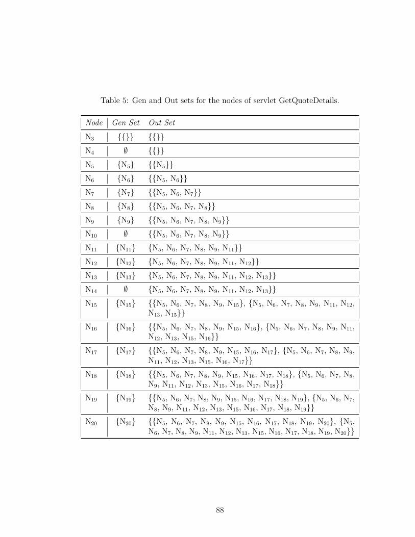
Table 5: Gen and Out sets for the nodes of servlet GetQuoteDetails.
Node Gen Set Out Set
N3 {{}} {{}}
N4 ∅ {{}}
N5 {N5} {{N5}}
N6 {N6} {{N5, N6}}
N7 {N7} {{N5, N6, N7}}
N8 {N8} {{N5, N6, N7, N8}}
N9 {N9} {{N5, N6, N7, N8, N9}}
N10 ∅ {{N5, N6, N7, N8, N9}}
N11 {N11} {N5, N6, N7, N8, N9, N11}}
N12 {N12} {N5, N6, N7, N8, N9, N11, N12}}
N13 {N13} {N5, N6, N7, N8, N9, N11, N12, N13}}
N14 ∅ {N5, N6, N7, N8, N9, N11, N12, N13}}
N15 {N15} {{N5, N6, N7, N8, N9, N15}, {N5, N6, N7, N8, N9, N11, N12,N13, N15}}
N16 {N16} {{N5, N6, N7, N8, N9, N15, N16}, {N5, N6, N7, N8, N9, N11,N12, N13, N15, N16}}
N17 {N17} {{N5, N6, N7, N8, N9, N15, N16, N17}, {N5, N6, N7, N8, N9,N11, N12, N13, N15, N16, N17}}
N18 {N18} {{N5, N6, N7, N8, N9, N15, N16, N17, N18}, {N5, N6, N7, N8,N9, N11, N12, N13, N15, N16, N17, N18}}
N19 {N19} {{N5, N6, N7, N8, N9, N15, N16, N17, N18, N19}, {N5, N6, N7,N8, N9, N11, N12, N13, N15, N16, N17, N18, N19}}
N20 {N20} {{N5, N6, N7, N8, N9, N15, N16, N17, N18, N19, N20}, {N5,N6, N7, N8, N9, N11, N12, N13, N15, N16, N17, N18, N19, N20}}
88

The main iterative portion of SummarizeMethod begins at line A16 by accessing
the first node in worklist, which is node N4. The In set of node N4 is the union of its
predecessors’ Out sets. Node N3 is the only predecessor, so In[N4] is equal to Out[N3].
Since Gen[N4] is the empty set, after the computation at line A22, Out′ is also {{}}.
The value of Out[N4] is updated, and node N4’s successor, node N5, is added to the
worklist. In[N5] is equal to Out[N4]. Since Gen[N5] contains a reference to itself,
the computation at lines A20–A22 sets Out′ to {{N5}}. Out[N5] is updated, and its
successor, node N6, is added to the worklist. The computation of the Out sets for
nodes N6–N9 proceeds similarly, each adding its Gen set to the previous In set. After
updating Out[N9], node N10 is added to the worklist. In[N10] is equal to Out[N9].
Since Gen[N10] is empty, Out[N10] is equal to In[N10]. Out[N10] is updated and node
N10’s successors, nodes N11 and N15 are added to the worklist. Continuing with the
analysis at node N11, In[N11] is equal to Out[N10]. Gen[N11] is added to this set, and
the process repeats similarly for nodes N12, N13 and N14. The analysis continues at
node N15, whose predecessors are nodes N10 and N14. In[N15] is the union of Out[N10]
and Out[N14], which is {{N5, N6, N7, N8, N9}, {N5, N6, N7, N8, N9, N11, N12, N13}}.
Gen[N15] is added to both sets in In[N15] to compute Out[N15]. This process repeats
for nodes N16–N20, each of which add their Gen set to the Out sets of the previous
node. After N20, there are no further nodes to process, so the worklist is now empty.
The analysis now continues at line A32, which begins the translation of the node
sets into the HTML they represent. At line A34, the exit node of jspService is
node N20, so lines A34–A42 will iterate over the two sets in Out[N20]. Line A36 begins
to iterate over each node in the first of these two sets. The call to resolve(N5) re-
turns the string “<html><body><h1>Get Quote Details</h1>,” which is appended
to htmlfragments. (For this example, we will assume reduce() does not remove any
tags. The next section will introduce an example of reduce() that removes tags.)
The call to resolve is repeated for each node in the node set, and its return value
89

is appended to htmlfragments. The result of analyzing the first node set is a string
whose content is concatenation of the HTML strings generated at nodes N5, N6, N7,
N8, N9, N15, N16, N17, N18, N19, and N20. The second node set is similarly analyzed
and generates a string whose content is the concatenation of the HTML generated at
lines N5, N6, N7, N8, N9, N11, N12, N13, N15, N16, N17, N18, N19, and N20. These two
strings comprise the method summary of jspService.
After jspService is summarized, the analysis returns to ExtractPages. The
method jspService is the root method, so the two strings in its summary are
assigned to pages. At this point, ExtractContent analyzes the strings in pages and
identifies the HTML elements of interest, which are returned at line A10. In this
example, ExtractContent simply returns the two unaltered HTML pages.
6.2 Identifying Links and Web Forms
Links and web forms contribute to the definition of important software abstractions
in web applications, such as control flow and invocations. The web forms generated
by a component define parameter names and input fields that will be part of an
invocation sent by the browser to the target component. Links can also contribute to
defining invocations since they are encoded as URLs and can provide parameters in
the URL’s query string. HTML based links can also represent control flow between
components of a web application that is not directly expressed in the general purpose
language of the web application. Identifying the links and web forms in the output of
a component allows quality assurance techniques to more completely define and use
the corresponding software abstractions.
Since links and web forms are primarily part of a component’s output, they can be
identified by the algorithm presented in Section 6.1. The output analysis algorithm
is customizable via Fragment Filtering, so the analysis can be customized to identify
links and web forms. In this section, I define the customizations of the Fragment
90

Filtering that facilitate the identification of links and web forms. I also use the
example from Section 6.1.4 to demonstrate how the Fragment Filtering works in
practice.
Although links are primarily defined in the generated HTML output of a web
application, its also possible for them to be defined via API calls in the general
purpose language of the web application. Many web application frameworks provide
commands, such as redirect or open, that can take a URL as a parameter. This URL
could represent a branch in the control flow of the web application or an invocation
of another component, neither of which would be accounted for in the traditional
CFG. Identifying and analyzing these links is fairly straightforward; however, for
completeness, I also outline an algorithm that identifies and processes these types of
links.
The rest of this section is organized as follows: Section 6.2.1 defines and illustrates
the customizations to the Fragment Filtering that allow for the identification of the
links and web form. In Section 6.2.2, I present the algorithm for identifying and
analyzing API based links.
6.2.1 Fragment Filtering for Links and Web Forms
As explained in Section 6.1.3, Fragment Filtering analyzes the HTML fragments and
removes tags that are not associated with the definition of the HTML elements of
interest. The removal is performed safely, so that the definition of HTML elements
of interest is not affected. To perform the Fragment Filtering, the reduce function
builds a parse tree of the HTML fragment it receives as input and then walks the tree
to mark and remove all non-contributing nodes. A node is a non-contributing node if
it does not contain a placeholder, is syntactically well-formed, and is not one of the
set of HTML tags associated with defining an HTML element of interest.
Only certain HTML elements can define either web forms or links. For web forms,
91

the following tags (and their corresponding closing tags, if applicable) can contribute
to their definition: <form>, <input>, <select>, <option>, and <textarea>. No
other HTML tags contribute to defining parts of the web form that correspond to
invocation-related information. The target of the invocation and HTTP request
method are defined as attributes of the <form> tag, and names of the parameters
in the invocation are defined by attributes of the <input>, <select>, <option>, and
<textarea> tags.
Links are similarly only defined by a few elements. By far, the most common
one is the anchor (<a>) tag, which contains a hyper-reference attribute that takes a
URL value. A user clicks on the visual representation of the link and the URL is
fetched. The query portion of the URL can contain a set of name-value pairs, which
turns the fetching of the URL into an invocation. Other tags also provide attributes
that can contain a URL. One example of this is the image (<img>) tag. The source
for the image is also a URL. Other tags that have URL based attributes include the
<script> and <frame> tags.
Illustration with Example
To identify links and web forms in GetQuoteDetails, the analysis proceeds in
the same manner as in Section 6.1.4, until it reaches line A32 of SummarizeMethod.
This is the point where the node sets are translated into their corresponding HTML
content. With the customized version of the Component Output Analysis, Fragment
Filtering no longer returns the unaltered HTML, it now filters for only the HTML
elements of interest.
To illustrate the Fragment Filtering, I continue the analysis at line A34 of Sum-
marizeMethod. The exit node of jspService is node N20, so lines A34–A42 will
iterate over Out[N20] (See Table 5). Line A36 iterates over each node in the first
of these two sets. Calling resolve(N5) returns the string “<html><body><h1>Get
92

Quote Details</h1>,” which is appended to htmlfragments. The call to reduce
at line A39 performs the Fragment Filtering detailed in the previous section. Using the
definition of non-contributing nodes, the <h1> tag and its enclosed data can be safely
eliminated, since it is syntactically well-formed, does not contain a placeholder, and
does not define either a link or a web form. Note that the <html> and <body> tags are
not removed since they are not well formed (i.e., , they lack their corresponding clos-
ing tags). The loop at line A36 processes node N6. The call to resolve returns “<form
action =‘‘QuoteController’’ method=Get>.” This is appended to the previously
reduced HTML fragment, so the call at line A39 is reduce(‘‘<html><body><form
action =‘‘QuoteController’’ method=Get>’’). The Fragment Filtering does not
reduce this fragment any further, since the <form> tag is part of the definition of a
web form. Nodes N7, N8, and N9, evaluate similarly to node N6. The HTML frag-
ments associated with nodes N15 and N16 both contain placeholders. This is because
the variables stateValue and ageValue are externally defined and cannot be resolved
to a concrete value within the current method context. Since this is the root method
of the component, the analysis will generate a warning to the developer about this
situation and assumes that these placeholders do not contain HTML content (i.e.,
they are placeholders for literal values). As stated earlier, this is almost always a
safe assumption for web applications. Nodes N17, N18, and N19 also contribute their
HTML fragments without any reduction from the Fragment Filtering. The last and
final addition of the HTML content at node N20 allows the <body> and <html> tags
to be removed from the summary since they are now well formed.
The HTML content saved for the first nodeset is shown in Figure 19(a). The
second node set is similarly analyzed and generates a string whose content is the
concatenation of the HTML generated by the nodes in the second nodeset. This
HTML content is shown in Figure 19(b). Together, the two HTML strings in Figure 19
comprise the method summary of jspService.
93

<form action=QuoteContro l l e rmethod=Get>
<input type=text name=name><input type=text name=type><input type=text name=year><input type=hidden
name=s t a t evalue=””>
<input type=hiddenname=agevalue=””>
<input type=hiddenname=QuoteInformationvalue=GetQuoteDetai ls>
<input type=submit></form>
(a) First node set.
<form action=QuoteContro l l e rmethod=Get>
<input type=text name=name><input type=text name=type><input type=text name=year><textarea name=i n c i d e n t s></textarea><input type=hidden
name=s t a t evalue=””>
<input type=hiddenname=agevalue=””>
<input type=hiddenname=QuoteInformationvalue=GetQuoteDetai ls>
<input type=submit></form>
(b) Second node set.
Figure 19: Link and web form content identified in GetQuoteDetails.
Table 6: Invocations generated by GetQuoteDetails.
# Target Argument Names
1 QuoteController {name, car, year, state, age, action}
2 QuoteController {name, car, year, incidents, state, age, action}
Once the HTML content associated with links and web forms has been identi-
fied, it can be analyzed to gather additional information about the web application.
The two HTML fragments in jspService’s summary are analyzed by an HTML
parser to identify invocations. This analysis identifies the attributes of the <form>,
<textarea>, and <input> tags, such as argument names and the target of the in-
vocation. Table 6 shows the two invocations that would identified by analyzing the
HTML fragments in Figure 19. The target of the invocation is identified by the
action attribute in the <form> tags, the names of the arguments are defined as the
name attribute in the <textarea>, and <input> tags.
94

6.2.2 Analyzing API Based Links
Components can perform invocations by creating a URL containing the invocation
and passing it to a specific API method. To identify such invocations, the technique
visits each node of the component’s inter-procedural control flow graph (ICFG), iden-
tifies all call sites that invoke API methods used to make direct invocations, and
analyzes the parameters of these calls to extract the invocation URL. For example,
in Java the parameter containing the URL is represented as a string. My technique
determines the value of the URL using the string analysis and then parses the URL
to identify information about the invocation’s target and arguments.
6.3 Implementation
I implemented the analyses described Sections 6.1 and 6.2 in a prototype tool called
the Component Output Analyzer (COA). The COA prototype is written in Java and
can analyze web applications built using Java Enterprise Edition (JEE). Although the
implementation targets only Java-based web applications, the analyses are generally
applicable to a wide range of other web development languages, such as PHP, ASP,
and Perl. COA analyzes each class in a web application and outputs a list of the
identified HTML elements of interest. Users can introduce their own implementation
of Fragment Filtering by replacing a JAR file that implements the Fragment Filtering
interface defined in COA. The analysis in COA leverages several other program
analysis libraries: (1) Soot program analysis framework3 to generate call graphs and
control-flow graphs. Soot uses an implementation of the Class Hierarchy Analysis
(CHA) [22] to resolve points-to information; (2) A modified version of JSA [20] to
perform string analysis, and (3) A customized version of HTML Parser4 to parse
HTML pages and fragments in the Fragment Filtering.
3http://www.sable.mcgill.ca/soot/4http://htmlparser.sourceforge.net/
95

6.4 Discussion of Analysis Limitation
The output of a component can include HTML markup and client-side JavaScript.
The analysis presented in Section 6.1 models the content of all of the output, re-
gardless of whether it represents HTML markup or JavaScript code. However, one
important limitation of my analysis is that it only considers the semantics of the part
of the output that represents HTML markup. This can cause inaccuracies in the
analysis because scripts written in JavaScript can perform a wide range of actions,
including communicating with other components and changing the HTML page at
runtime. These actions could potentially affect the definition of web forms or links
in an HTML page. Since my approach does not account for the semantics of these
JavaScript actions, the changes to the HTML elements would go undetected. The
result of this is that my analysis technique will identify output that would actually
be different from the actual output because of actions performed by the scripts.
Analysis of the semantics of the generated JavaScript is challenging and is of itself
an ongoing area of research. JavaScript presents many challenges for static analysis
because it is loosely typed and can create and execute JavaScript commands on the
fly (e.g., via an eval function). As discussed further in Chapter 8, the impact of
JavaScript on the accuracy of quality assurance techniques is low. For the most
part, JavaScript is used to modify and affect operations that do not impact the
correct identification of links or web forms. Nonetheless, the growing use of JavaScript
motivates the need to include its semantics in approaches oriented towards AJAX
based web applications.
96

CHAPTER VII
TEST-INPUT GENERATION
Test-input generation is an important underlying technique for many quality assur-
ance tasks. High-quality test inputs allow testers to more completely execute the
application and possibly discover more errors. For test-input generation, knowing the
interfaces of an application is a necessary step. The interfaces (e.g., the signatures of
a method) tell the tester what parameters must be supplied in a valid test case and
can also specify domain information about those parameters. The lack of such ex-
plicitly defined interfaces for web applications means that testers must rely on other
techniques to identify interfaces. If these techniques are incomplete or not precise
enough, parts of the application may remain untested, and could contain faults that
may be exhibited in the field or vulnerabilities that can be exploited by attackers.
Existing techniques for interface identification have limitations that negatively
impact the effectiveness of test-input generation for web applications. Techniques
that rely on developer-supplied specifications [8, 41, 67] can provide an indication
of the intended interfaces of a web application, but if the implementation differs
from the specification, testing may be inadequate. With dynamic techniques [25, 38],
lack of completeness creates similar limitations for testing. Parts of the application
that are not discovered via interactions with the web application will go untested.
Lastly, even techniques that perform static analysis but discover inadequate domain
information [23] can lead to incomplete testing. Consider QuoteController in Figure 9.
Without the domain information that specifies that “userAction” must be equal to
“CheckEligibility,” a test-input generator must guess the correct relevant values, or
lines 5–23 will not be executed.
97

In the rest of this chapter, I describe test-input generation in more detail and
present the results of an empirical evaluation focused on the usefulness of my interface
identification approaches. In the evaluation, I compare test-input generation using
interface information identified by my analysis (Chapter 5) against the results of
test-input generation using other interface identification approaches. The results are
compared based on structural coverage and the number of test cases used to achieve
that coverage.
7.1 Approach
The technique that I use for test-input generation is fairly straightforward with respect
to how it uses interface information. For each identified interface of an application,
the test-input generation creates sets of test-inputs that satisfy the interface’s domain
constraints. However, each of the four approaches I evaluate differs slightly in the
structure of the interface information discovered. So, for each approach, I explain
how its interface information is used to create test inputs.
wam-se: For the wam-se approach, generating test inputs is conceptually straight-
forward. An interface domain constraint (IDC) corresponds to the constraints
introduced by a specific path. Each IDC is submitted to a constraint solver,
and the values in the solution are used as test inputs. For values that are un-
bound by any constraint in the IDC, the constraint solver generates a random
string. Although it is possible that an IDC may contain constraints that cannot
be solved, in practice, all of the constraints identified in the subject applica-
tions were fairly simple and were solved by the constraint solver. The wam-se
approach is described in more detail in Section 5.2 and its implementation in
Section 5.2.2.
98

wam-df: Domain information in the wam-df approach is tracked per callsite. The
primary complication that this introduces is that the domain information as-
signed to a name-value pair is not path sensitive, so there is no way to correlate
domain information for different name-value pairs and know which ones go to-
gether on the same path. The implications of this are that to ensure that all
correct combinations are tested, the set of test inputs that must be used is the
Cartesian product of all of the domain constraints identified for each name-value
pair in an interface. If a name-value pair does not have any domain constraints
associated with it, a random string is used as its value. For example, con-
sider QuoteController in Figure 9. Parameters “actionValue” and “state” each
have two domain constraints. In this example, “actionValue” is either equal to
“CheckEligibility” or “QuoteInformation,” and “state” is not equal to “GA”
or the empty string. By examining the application, it is clear that the first
and second constraint for each parameter should go together and coverage can
be achieved on both paths using two test inputs. However, wam-df must use
the Cartesian product of all of the domain constraints. This results in four
sets of test inputs, which achieves coverage, but with more test inputs than
needed. The wam-df approach is described in more detail in Section 5.1 and
its implementation in Section 5.1.2.
spider: The spider approach is based on the OWASP WebScarab Project,1 which
is a widely-used Java-based implementation of a web crawler. I extended the
OWASP spider by adding to it the capability of extracting interface related
information from each web page it visited during the crawl by parsing the
HTML and analyzing web forms and links. (Typically, these HTML elements
are used by web application testers to infer the interfaces of a web application.)
1http://www.owasp.org/index.php/Category:OWASP_WebScarab_Project
99

The spider approach does not normally collect domain information during a
crawling of a web application. So to collect this information I also extended the
approach to record default values, if present, that have been provided in the web
forms and links. Since these values are supplied by the web application, they are
a good source of legal values for the name-value pairs and can be reused as test
inputs. If no default values are discovered for a name-value pair, a randomly
generated string is used as the value. Additionally, I enabled the spider to
perform the most thorough exploration possible by giving it administrator-level
access to the subject web applications.
dfw: The dfw approach was developed by Deng, Frankl, and Wang [23] in 2004.
The original purpose of dfw was to model basic attributes of a web appli-
cation. As part of this technique, dfw identifies some of the same type of
interface information as my interface analysis approaches, namely, the names of
the name-value pairs. The primary difference between dfw and my techniques
is that dfw does not identify domain information or group parameter names
into logical interfaces. These differences complicate test-input generation. To
address the first of these differences, I assume all parameters identified by dfw
should be defined in each set of test inputs (i.e., they are all part of the same
interface). This is less than ideal, as some web application code checks for the
presence of defined parameters and responds differently based on which param-
eters are defined, but this reflects a limitation of the information provided by
this approach. For the domain information, I assign each name-value pair a
random alphanumeric string, an empty string, or a numeric value. These values
are used since they correspond to common checks or domain constraints within
web application code and can therefore increase code coverage. For the imple-
mentation, the authors provided me with the original dfw implementation, and
I used their code as a guide to reimplement the technique so that it would work
100

within my analysis framework. I also extended the technique to address an
implementation limitation where it could only identify names that were defined
by constant strings in the same method scope.
7.2 Evaluation
The purpose of the evaluation is to determine whether interface information can im-
prove test-input generation. To do this, I compare my two approaches for interface
identification, wam-df and wam-se, against two currently proposed alternative ap-
proaches, spider and dfw. This evaluation used five of the ten subject applications
introduced in Chapter 3. Those for which I did not have wam-se based information
were not included. (See Section 5.3 for a discussion on the reasons why wam-se could
not be run for all applications.) In the evaluation, I consider two research questions.
The first is related to the effectiveness of my interface information in improving test-
input generation, which is measured by structural coverage of the web applications.
The second is related to the practicality of using the information, which is measured
in the number of test cases generated. The two research questions are as follows:
RQ1: Effectiveness – Do my interface identification techniques lead to higher test
criteria coverage of the web applications than spider and dfw?
RQ2: Practicality – Are the number of test-inputs lower for my techniques than for
spider and dfw?
7.2.1 RQ1: Criteria coverage
To address the first research question, I measured the coverage achieved on the subject
applications by test suites generated using interface information identified by the four
approaches discussed in Section 7.1. For each of these approaches, I generated test
inputs that satisfied all of the IDCs identified by the approach. For techniques that
did not explicitly identify IDCs, I used the heuristics described in Section 7.1 to create
101

appropriate values. For example, for dfw I assigned each name-value pair a random
alphanumeric string, an empty string, or a numeric value. The only exception to this
was Portal. For the wam-df and spider approaches, test suites that satisfied all of
the IDCs contained over 20 million different test inputs. This many test inputs would
have taken over 10 days to run. To reduce the number of test inputs for these two
approaches, I randomly chose IDCs to generate test cases until approximately 5% of
the estimated test cases were generated for each approach. In Tables 7, 8, and 9, the
corresponding coverage and test suite size numbers are marked with an asterisk (*)
as a reminder that these test suites were sampled down in size.
To measure the coverage achieved by each interface identification approach, I ran
the generated test suites against their target application. These test inputs were
submitted directly to the application, instead of through the application’s web forms,
in a process called bypass testing [61]. Some of the applications required a priming
script to be executed before the actual test inputs were run (e.g., a login to create a
session ID). For these applications, the testing infrastructure ran the priming script
before each test input. I measured the coverage achieved using three coverage criteria:
basic block, branch, and database command-form. Basic block coverage measures
the number of distinct basic blocks of the program that are executed by a test suite.
Branch coverage measures the number of distinct branches (e.g., the true or false
branches of each if) that are traversed during the execution of a test suite. To monitor
these two criteria, I used Cobertura,2 a coverage tool for Java-based applications.
Database command-form coverage measures the number of distinct types of database
commands generated by an application [35]. Since most web applications are data-
centric, database command-form coverage is useful to determine if the application is
exhibiting different behaviors with respect to its underlying database. To measure
command-form coverage I used ditto [35], a tool that I developed in previous work.
2http://cobertura.sourceforge.net/
102

Table 7: Block and branch coverage achieved on subject web applications.
Block (%) Branch (%)Subject Wdf Wse Spi. dfw Wdf Wse Spi. dfw
Bookstore 84.1 87.3 75.6 68.7 55.2 59.7 42.1 34.8
Classifieds 81.6 83.7 76.0 66.3 51.3 54.8 41.7 32.3
Empl. Dir. 83.0 84.6 76.4 69.3 52.9 56.1 42.4 34.9
Events 83.5 84.8 76.8 68.2 55.3 57.2 43.9 34.5
Portal 57.2* 86.6 53.7* 71.0 30.5* 59.3 24.9* 36.8
Average 78 85 72 69 49 57 39 35
Table 8: Command-forms covered in subject web applications.
Command-forms (#)Subject Wdf Wse Spi. dfw
Bookstore 88 737 63 54
Classifieds 96 366 99 19
Empl. Dir. 30 351 22 16
Events 37 186 22 16
Portal 345* 2,964 362* 55
Average 119 921 114 32
The results of this study are presented in Table 7 and Table 8. Table 7 shows,
for each application and approach (Wdf , Wse and Spi., and dfw), the level of basic
block (Block) and branch (Branch) coverage achieved by the test cases. The numbers
shown represent a percentage. Table 8 shows the amount of command-forms covered
by the test cases. This number represents the actual number of command-forms
covered instead of the percentage, since ditto cannot accurately estimate an upper
bound on the total number of test requirements for this criterion.
The results in Table 7 and 8 show almost consistently higher coverage for the
103
wam-df and wam-se approaches. For all of the subjects and criteria, the wam-se
based test suites had the highest amount of coverage. This approach averaged 7%
higher block coverage, 8% higher branch coverage, and covered over 7 times as many
command-forms as compared to the next best approach, which was wam-df. The
wam-df approach also did well and was consistently higher than the remaining two
approaches. The only exception to this was Portal, where the dfw approach showed
higher coverage than the wam-df approach. This was most likely due to the fact
that, as mentioned previously, the full wam-df and spider based test suites were
randomly sampled down in size. Nonetheless, wam-df averaged 6% higher block
coverage, 10% higher branch coverage, and five more command-forms per subject
than the best score of either of the two remaining approaches.
One particularly interesting trend in the data was that command-form coverage
(shown in Table 8) had a higher relative increase with the wam-se approach than the
other metrics. Case in point, the percentage increase in branch and block coverage, as
compared to wam-df, was less than 10%, but the increase in command-form coverage
was over 7X. I manually inspected several of the servlets to investigate this increase. I
found that many branch conditions in the subjects compare hard-coded strings against
the value of the argument or check that an argument’s value is numeric. Both of my
approaches identify these types of constraints and generate test cases that cause them
to be covered. However, wam-se has the advantage that it can model the constraints
of two arguments being equal to each other. For example, in registration pages, a
servlet only proceeded if the user entered the same new password twice. The other
approaches were not able to model these types of constraints and were thus unable to
get high coverage of these servlets. I also found that database queries were built using
multiple nested if statements. Therefore, even though the branch increase provided
by wam-se was small, the few additional covered branches resulted in a significant
increase in command-form coverage.
104

Table 9: Size of test suites for test-input generation.
Size of test suiteSubject Wdf Wse Spi. dfw
Bookstore 258,565 10,634 68,304 33,279
Classifieds 47,352 3,968 7,238 10,732
Employee Dir. 627,820 3,772 46,099 54,887
Events 36,448 1,735 4,145 5,566
Portal 1,000,000* 11,243 750,000* 1,550,029
Total 1,970,185 31,352 875,786 1,654,493
7.2.2 RQ2: Number of test inputs
In the second research question, I addressed the issue of practicality of the different
approaches. For practicality, I measured the number of test inputs generated for
each approach. Since the time to run test inputs is roughly linear with respect to
the number of test inputs, this measurement gives an indication of the amount of
resources necessary to achieve the coverage numbers presented in the previous study.
For each application, Table 9 shows the number of test inputs generated using the
interface information identified by each approach. This number represents the number
of test cases that were generated using the available interface information. Note that
two of the test suites for Portal were sampled down in size and are denoted with an
asterisk (*).
The numbers in Table 9 lead to two interesting observations. The first is that the
size of wam-df based test suites is significantly larger than those of other approaches.
This result is not surprising given the conservative technique used to estimate the
domain information of each name-value pair. The conservative approximation of the
domain information leads to the use of IDCs for test-input generation that do not
correspond to feasible paths. (This aspect of wam-df is discussed in more depth
105
in Sections 7.1 and 5.3.) The second observation is that the test suites for wam-se
are significantly smaller than the test suites generated using the other approaches.
In some cases, the test suites are an order of magnitude smaller, but still generate
higher coverage than all other approaches. Because of the increased precision of the
wam-se approach, there are a fewer number of IDCs, which leads to a lower number
of test inputs. However, since the IDCs are more precise and can model more types of
constraints (e.g., arithmetic constraints), they achieve better coverage. Overall, the
results show that interface information generated by wam-df leads to the generation
of more test inputs than other approaches. As compared to dfw and spider this
increase leads to higher coverage. However, the increased precision of wam-se leads
to greater efficiency; more coverage is achieved using significantly fewer test inputs.
7.3 Conclusions
Overall, the results of the evaluation show that test-input generation can be improved
by the use of my interface identification approaches. Test suite generation based on
the wam-df approach led to higher coverage than spider and dfw across all of the
measured criteria. However, this increased coverage came at the cost of increased
test suite size. The wam-se approach improved coverage over the wam-df approach,
while at the same time using over an order of magnitude fewer test cases. Although
the wam-se analysis requires more set up and configuration time, the results of this
empirical evaluation suggest that this time is justified by the benefits of increased
coverage with significantly smaller test suites.
106

CHAPTER VIII
INVOCATION VERIFICATION
The components of a web application communicate extensively to provide a feature-
rich environment that integrates content and data from multiple sources. As explained
in Chapter 2, communication between web components is different than that between
traditional program modules. When a web component A communicates with another
component B, it does so by sending an HTTP request to B that invokes one of
B’s accepted interfaces and provides a set of arguments in the form of name-value
pairs. An error in this communication can occur for several reasons: B may expect
additional arguments, A or B may refer to the same argument by different names,
or A may send too many arguments. I refer to these types of errors as parameter
mismatches.
For modern web applications, parameter mismatches have become a serious and
common problem. In fact, a recent empirical study [24] reported that parameter
mismatches are one of the most frequent types of errors made by web application
developers. The complexity of inter-component communication, where both the gen-
eration of interface invocations and the definition of a component’s accepted interfaces
occur at runtime, contributes to the likelihood of these errors occurring. Because pa-
rameter mismatches affect the ability of web components to communicate correctly,
this type of error can be serious and can cause a component to fail unexpectedly or
return incorrect results.
Automatically identifying parameter mismatches in modern web applications is
challenging for current testing and analysis techniques. Many current techniques
were designed for simple static web applications, which contain hard-coded interface
107

invocations. For these applications, it is sufficient to inspect their HTML code and
ensure that each invocation contains the correct arguments and matches an accepted
interface of the target component. For modern web applications, which are generally
more complex and dynamic, the presence of implicitly defined accepted interfaces and
dynamically generated invocations precludes such a straightforward solution.
Using my analysis techniques, I developed a technique to automatically identify
parameter mismatches in web applications. This technique is able to handle com-
plex web applications that dynamically generate interface invocations in HTML and
have implicitly defined accepted interfaces. In the rest of this chapter, I discuss my
technique in more detail and illustrate it using the example web application. I also
present the results of an evaluation of the invocation verification technique. In the
evaluation, I report on the time needed to perform the various steps of the verification
and determine the precision of the technique.
8.1 Technique to Identify Parameter Mismatches
The goal of my technique is to automatically identify parameter mismatches in web
applications. To do this, the technique performs a static verification of the invocations
made by the web application. The approach consists of three main steps. Step 1
identifies the accepted interfaces of each component in the web application. Step
2 analyzes each component to determine its set of interface invocations. Finally,
Step 3 checks whether each interface invocation matches an accepted interface of the
invocation’s target. In the following sections, I describe each step of the technique in
more detail.
8.1.1 Step 1: Identify Interfaces
The first step of the technique identifies the accepted interfaces of each web com-
ponent. To do this, the technique uses the information generated by the interface
108

Table 10: Data-flow based interface information for QuoteController.
# Interface
1 {action}
2 {action, age, state}
3 {action, name, state, age}
4 {action, age, state, name}
5 {action, name, state, age, type, year}
6 {action, age, state, name, type, year}
analysis techniques presented in Chapter 5. Note that the verification itself is not de-
pendent on a specific interface identification technique. As long as the information is
expressed in a standardized form, it can be used for verification purposes. Although,
both interface analysis techniques also generate IDCs, this information is not used as
part of the verification process.
For illustrative purposes, Table 10 shows the accepted interfaces of QuoteCon-
troller that were identified by the data-flow based interface analysis (Chapter 5). The
information in this table is based on a summarization of information shown in Ta-
ble 2 of Chapter 5. The first column (#) shows the interface number and the second
(Interface) lists the names of the parameters that comprise the interface.
8.1.2 Step 2: Determine Invocations
The second step of the technique identifies each component’s set of interface invo-
cations. To do this, the technique uses the customized component output analysis
described in Chapter 6. The customized analysis identifies the invocations generated
by the component via links, web forms, and API calls.
For illustrative purposes, Table 11 shows the invocations of GetQuoteDetails that
are identified by the customized output analysis (Chapter 6). For each of the two
109

Table 11: Invocations generated by GetQuoteDetails.
# Target Argument Names
1 QuoteController {name, car, year, state, age, action}
2 QuoteController {name, car, year, incidents, state, age, action}
invocations, the table shows the invocation’s target (Target) and the names of the
arguments defined in the invocation (Argument Names).
8.1.3 Step 3: Verify Invocations
The third and final step of the technique verifies each component’s interface invo-
cations. For each identified invocation, the technique identifies the target of the
invocation and checks that the invocation matches one of the target’s accepted inter-
faces. An invocation matches an accepted interface if the invocation’s set of argument
names equals the names of the parameters in the accepted interface. Each invocation
that does not match an accepted interface is reported to the developers as a potential
error.
VerifyInvocations, which is shown in Algorithm 9, verifies the invocations. The
input to VerifyInvocations is a set of interface invocations, and the output is the set
of parameter mismatches. For each invocation, invk, the algorithm first identifies the
target component of the invocation (line 3) and the accepted interfaces of the target
component (line 4). Before beginning the main loop, the algorithm initializes invokeok
to false (line 5). This boolean flag is used to track when a matching interface has
been found in the accepted interfaces. The algorithm then iterates over each accepted
interface, interface (lines 6–10). match returns true only if invk matches interface
(line 7). When a match is found, the invokeok flag is set to true (lines 8). Finally,
if there is no match, invk is added to mismatches (lines 11–13), and mismatches
contains the output of VerifyInvocations (line 15).
110

Algorithm 9 VerifyInvocations
Input: invocations: set of interface invocationsOutput: mismatches: set of invocations with parameter mismatches
1: mismatches← {}2: for all invk ∈ invocations do3: target← target component of invk4: acptinterfaces← accepted interfaces of target5: invokeok ← false6: for all interface ∈ acptinterfaces do7: if match(invk, interface) then8: invokeok ← true9: end if
10: end for11: if not invokeok then12: mismatches← mismatches ∪ invk13: end if14: end for15: return mismatches
To illustrate, consider the verification of GetQuoteDetails’s invocations, which
are shown in Table 11. VerifyInvocations iterates over the first invocation. The
target of the invocation is QuoteController, so acptinterfaces is assigned to the
set of QuoteController’s accepted interfaces, which are shown in Table 10. Then
VerifyInvocations compares the first invocation against each of the accepted in-
terfaces. The first invocation does not match any of the accepted interfaces. This
happens for two reasons: (1) The invocation contains the argument “incidents,” which
is not used by QuoteController, and (2) GetQuoteDetails labels the argument that
contains the car type as “car” instead of “type,” which is how QuoteController refers
to the same argument. As a result of these two mismatches, the invocation is classi-
fied as a mismatch. The process is repeated for the second invocation. Here again,
the invocation does not match any of the accepted interfaces because of the second
reason above, so it is also classified as a mismatch. Both parameter mismatches are
returned to the developer for debugging. At this point, the developer would inspect
the parameter mismatches and identify their root causes.
111

WAIVE
WebApp
InterfaceAnalysis
Parameter MismatchReport
OutputAnalysis
VerifyInvocations
Figure 20: Architecture of the waive tool.
8.2 Implementation
I developed a prototype implementation of the technique for invocation verification.
The prototype, called Web Application Interface Verification Engine (waive), is writ-
ten in Java and can analyze web applications built using Java Enterprise Edition
(JEE). Although the implementation targets only Java-based web applications, the
approach is generally applicable to a wide range of other web development languages,
such as PHP, ASP, and Perl. waive analyzes the classes in a web application and
outputs a list of interface invocations that do not match any accepted interface. The
architecture of waive is shown in Figure 20. waive consists of three modules that
implement the three steps of the technique. The first module, which extracts ac-
cepted interfaces, uses interface information in a standardized XML format. For the
evaluation (Section 8.3), I implemented filters to convert interface information from
both of my interface identification approaches into this standardized format. The sec-
ond module, which identifies invocations, uses the implementation of the customized
output analysis described in Chapter 6. The third module implements Algorithm 9,
which was presented in Section 8.1.3.
112

8.3 Evaluation
The goal of the evaluation is to assess the usefulness and effectiveness of the invocation
verification technique. To perform this assessment, I measured the time required
to run the verification and its accuracy in identifying parameter mismatches. The
evaluation addresses the following two research questions:
RQ1: How efficient is the technique when run on real web applications?
RQ2: What percentage of the reported parameter mismatches represent actual errors
in the web applications?
8.3.1 RQ1: Efficiency
To address RQ1, I ran waive against the subject applications and, for each subject,
measured the time necessary to complete the three steps of the approach. I also noted
cases in which it was not possible to run the analysis, due to either memory limitations
or problems with libraries used in the implementation. I performed the experiments
on a single machine with a Pentium D 3.0Ghz processor running GNU/Linux 2.6
and 2GB of memory, of which 1.5GB was dedicated to the heap space of the Java
virtual machine (JVM). Table 12 shows the measurements for each of the subject
applications. For each application, I show the time taken to perform each step (Step
1, Step 2, and Step 3 ), and the total amount of time for all three steps (Total).
Note that the values in the column labeled Step 1 partially reproduce timing data
presented in Chapter 5.
The measurements in Table 12 show that the verification process for each applica-
tion took from 1,779 to 16,953 seconds (i.e., from 30 minutes to five hours, roughly).
The timing measurements obtained in the study indicate that the technique, although
expensive, is efficient enough to be incorporated into existing quality assurance pro-
cesses. Anecdotal evidence indicates that the execution time of this technique is
significantly faster than manual inspection. Although I did not formally measure the
113

Table 12: Verification timing results (s).
SubjectStep 1 Step 2 Step 3 Total
Wdf Wse Wdf Wse
Bookstore 2,322 1,479 462 1 2,785 1,942
Checkers 160 - 23,727 1 23,888 -
Classifieds 1,797 766 177 1 1,969 944
Daffodil 1,271 - 4,724 1 5,996 -
Empl. Dir. 741 905 104 1 846 1010
Events 333 586 105 1 439 692
Filelister 248 - 1,458 1 1,707 -
JWMA 1,589 - 10,126 1 11,716 -
Officetalk 207 - 142 1 350 -
Portal 988 1,528 482 1 1,471 2,011
time associated with manual inspection, my experience during the testing and evalu-
ation of waive gives a point of comparison. While developing waive, I verified the
implementation by manually calculating sets of interface invocations and accepted
interfaces for a subset of the servlets. Although I was familiar with the applications,
it took close to 12 hours to inspect the code and derive the correct sets for just four
classes.
8.3.2 RQ2: Precision
To investigate RQ2, I ran waive on the subject applications and checked the param-
eter mismatches reported by the tool. I manually inspected the code that generated
every mismatch to determine whether the mismatch represented an actual error or
was a false positive. The inspection also enabled me to determine the root cause of
the mismatch. This study only looked at false positives for two reasons: (1) there
was no previous technique for detecting parameter mismatches that the results of my
114

Table 13: Summary of invocation verification.
Subject Total Invk.Mismatches
False Pos. ErrorsWdf Wse Wdf Wse
Bookstore 26 0 0 12 11
Checkers 8 0 - 4 -
Classifieds 20 0 0 12 14
Daffodil 23 11 - 1 -
Empl. Dir. 10 0 0 4 5
Events 12 0 0 0 4
Filelister 4 0 - 3 -
JWMA 124 7 - 117 -
Officetalk 26 0 - 3 -
Portal 24 0 1 2 10
Total 277 18 1 159 43
technique could be compared against, and (2) the subject web applications did not
have any previously reported parameter mismatches.
Table 13 shows the results of the second study. For each application, I list the num-
ber of interface invocations (Total Invk.) and the number of the reported mismatches
classified as either false positives (False Pos.) or confirmed parameter mismatches
(Errors). The results are further classified depending on the source of the interface in-
formation used. The results achieved using the data-flow based approach are listed as
Wdf , and the results obtained using the symbolic execution based approach are listed
as Wse. As the results show, waive using the data-flow based interface information
correctly identified 159 parameter mismatches and generated 18 false positives. Using
the symbolic execution based interface information, waive correctly identified 43 pa-
rameter mismatches and generated 1 false positive. Although the symbolic execution
based approach discovered less mismatches in total, this can be attributed to the fact
115

Table 14: Classification of confirmed parameter mismatches.
SubjectConfirmed Parameter Root CausesMissing Syntax Ignored
Wdf Wse Wdf Wse Wdf Wse
Bookstore 6 10 2 0 4 1
Checkers 0 - 2 - 2 -
Classifieds 8 11 0 1 4 2
Daffodil 0 - 0 - 1 -
Empl. Dir. 5 4 0 0 0 0
Events 0 4 0 0 0 0
Filelister 1 - 2 - 0 -
JWMA 33 - 17 - 67 -
Officetalk 2 - 0 - 1 -
Portal 2 10 0 0 0 0
Total 57 39 23 1 79 3
that it was a viable approach for only half of the subject web applications. Overall,
both approaches had a relatively low rate of false positives (about 10% for Wdf and
2% for Wse). This suggests that the technique would be useful for developers, as most
of the reported mismatches were caused by actual errors in the web applications.
For each confirmed parameter mismatch, I further analyzed the code in order to
determine the root cause of the mismatch. The results of this analysis are shown
in Table 14. I classified the root cause of each mismatch according to the following
categorization:
Ignored parameter: An argument in the invocation is not accessed by the target
component.
Missing parameter: An invocation does not contain an argument that is accessed
by the accepted interfaces of the target component.
116

Syntax error: An invocation does not match because of a misspelling in an argu-
ment name or a formatting error in the invocation (e.g., in an HTML tag or
URL string).
As the results in Table 14 show, parameter mismatches due to ignored parameters
occurred with the highest frequency. This type of mismatch is very difficult to detect
during testing. The reason for this is that the invocations contains extra name-
value pairs that are simply not used by the target component. Therefore, at best,
the only observable symptom is an HTML page that does not reflect the use of the
extra information, and identifying or precomputing the subtle change in the output
that corresponds with an unused parameter is a substantial effort. The second most
common mismatch, missing parameters, represents scenarios where additional name-
value pairs were accessed by the target but not provided in the invocation. In most
cases, this type of error leads to a crash, as the value returned is null. However, not
all mismatches in this category are necessarily errors. During my manual inspection, I
found cases where the developers had placed error handling code around the access of
the name-value pair. This suggests that the developers could have felt that supplying
the name-value pair was optional, and not necessarily required for execution. On the
other hand, it could also be good defensive coding. Without a specification of the
correct behavior and usage of the component, it is difficult to make this determination.
Finally, the occurrence of the last group of mismatches, syntax errors, highlights one
of the problems with creating invocations via web forms and links. This technique
forces developers to remember the exact spelling of each of the parameters that must
be supplied. The prevalence of mismatches in this category indicates that this can be
difficult for developers.
In the manual inspection of the code, I found that the impact of the defects
varied widely. Most would cause null pointer exceptions, but for some, the errors
were more subtle. For example, in Filelister two mismatches led to incorrect filtering
117

Table 15: Classification of false positive parameter mismatches.
SubjectFalse Positive Root Causes
WAM JavaScript R & IWdf Wse Wdf Wse Wdf Wse
Bookstore 0 0 0 0 0 0
Checkers 0 - 0 - 0 -
Classifieds 0 0 0 0 0 0
Daffodil 2 - 3 - 6 -
Empl. Dir. 0 0 0 0 0 0
Events 0 0 0 0 0 0
Filelister 0 - 0 - 0 -
JWMA 0 - 7 - 0 -
Officetalk 0 - 0 - 0 -
Portal 0 1 0 0 0 0
Total 2 1 10 0 6 0
of a search query and caused the application to return erroneous results to the end
user. In Bookstore, three mismatches allowed a user to click a link to display updated
information, but the intended action was not completed and no error message was
displayed to the user. The result of one of the mismatches in JWMA was that a data
field associated with a customer’s profile was not saved. Through the code inspection,
I also found that the actual errors that led to the mismatches ranged from complicated
logic to typos in the names of arguments and parameters. For example, four of the
mismatches in Bookstore were due to erroneous logic in the target components that
did not anticipate legal combinations of arguments. Conversely, the errors in Filelister
and JWMA were caused by a syntax error in an indirect invocation and a misspelling
of the name of an accessed parameter, respectively.
I analyzed the false positives to determine their root causes. Table 15 shows the
result of this analysis. I classified each root cause using the following categories:
118

WAM: These false positives are due to limitations in the implementation of the inter-
face identification approaches; the implementations may miss interface elements
of the target component in cases where a web application uses non-standard
ways of extracting parameters from a request object.
JavaScript: JavaScript code in a generated HTML page can add additional argu-
ments to an invocation before it is submitted to the target component. Neither
approach analyzes JavaScript, so they cannot detect changes to the affected
invocation done via JavaScript.
Redirects and Imports: A web application component can redirect requests to
other components or import code fragments that change the component’s set of
interface invocations or accepted interfaces. Neither analysis accounts for the
effects of redirections and imports.
As the results in Table 15 show, the two dominant root causes of false positives are
“JavaScript” and “Redirects and Imports.” Although addressing these limitations is
conceptually straightforward and would eliminate most of the related false positives, it
would require non-trivial extensions to the implementation of the technique. I there-
fore decided to postpone these extensions to a later stage of the research. The third
root cause, “WAM,” can be addressed by improving the precision and completeness
of the analysis techniques for accepted interfaces.
The results of the evaluation show that the false positive rate of the technique is
low. Only one of the applications, Daffodil, had a high false positive rate. However,
as explained earlier, these can be eliminated with further engineering. Overall, the
false positive ratio is low and suggests that my technique is a useful approach for
detecting parameter mismatches.
119

8.4 Conclusions
Overall, the results of the evaluation are positive. Invocation verification was able to
discover many incorrect invocations in the subject applications with a relatively low
false positive rate. Since there were no previous techniques for discovering parameter
mismatches in web applications, many of these errors might have remained undiscov-
ered until found by users in deployed web applications. Additionally, the results of
the evaluation show that invocation verification is practical and can be accomplished
in a reasonable amount of time.
120

CHAPTER IX
PENETRATION TESTING
Detecting and preventing vulnerabilities in web applications has become an important
concern for software developers. Many companies use web applications to gather and
maintain customer information. As a result, these applications must often store in-
formation that is confidential. If attackers obtained this information, the result could
be substantial losses to both consumers and companies. Case in point: Analysts esti-
mate that the average data breach costs a company more than 4.5 million dollars [64].
Unfortunately, vulnerabilities that lead to these incidents are far from rare. Reported
vulnerabilities since 2001 have grown at a rate of 150% per year, and web applications
have overtaken desktop software as the most vulnerable platform [60]. The rising cost
and incidence of successful attacks has increased the importance of techniques that
identify vulnerabilities in web applications.
One such technique, penetration testing, has become widely used by software
developers. Penetration testing identifies vulnerabilities in web applications by sim-
ulating attacks by a malicious user. Developers use information about which attacks
were successful to find vulnerabilities and improve the security of the web application.
Penetration testing is popular among developers for several reasons: (1) it generally
has a low rate of false vulnerabilities because it discovers vulnerabilities by exploiting
them; (2) it tests applications in context, which allows for the discovery of vulnerabil-
ities that arise due to the actual deployment environment of the web application; and
(3) it provides concrete inputs for each vulnerability that can guide the developers
in correcting the code. The widespread usage of penetration testing has led many
government agencies and trade groups, such as the Communications and Electronic
121

Attack
Generation
Response
Analysis
Report
Information
Gathering
AttacksInformation
Responses
Target
Selection
Analysis
feedback
Pen Tester
Web
Application
Figure 21: The penetration testing process.
Security Group in the U.K., OWASP,1 and OSSTMM,2 to accredit penetration testers
and establish standardized “best practices” for penetration testing.
Although individual penetration testers perform a wide variety of tasks, the gen-
eral process can be divided into three phases: information gathering, attack gener-
ation, and response analysis. Figure 21 shows a high-level overview of these three
phases. Penetration testers select a target web application and begin the informa-
tion gathering phase. In this phase, penetration testers obtain information about the
target application using techniques that include automated scanning, web crawlers,
and social engineering. The results of this phase allow penetration testers to perform
the attack generation phase, which is the development of attacks on the target ap-
plication. Often this phase can be automated by customizing well-known attacks or
using automated attack scripts. Once the attacks have been executed, penetration
testers perform response analysis — they analyze the application’s responses to de-
termine whether the attacks were successful and then prepare a final report about
the discovered vulnerabilities.
During information gathering, the identification of an application’s input vectors
1http://www.owasp.org/2http://www.osstmm.org/
122

(IVs) — points in an application where an attack may be introduced, such as user-
input fields and cookie fields — is of particular importance. Better information about
an application’s IVs generally leads to more thorough penetration testing of the appli-
cation. Currently, it is common for penetration testers to use automated web crawlers
or similar black-box techniques to identify the IVs of a web application [2, 43, 79, 82].
A web crawler visits the HTML pages generated by a web application and analyzes
each page to identify potential IVs. The main limitation of this approach is that
it is incomplete because web crawlers are typically unable to visit all of the pages
of a web application or must provide certain values to the web application to cause
additional HTML pages to be shown. Although penetration testers can effectively
use the information discovered by web crawlers, the potential incompleteness of such
information can result in a large number of vulnerable IVs remaining undiscovered.
One of the example servlets, DisplayQuote (Figure 11), contains a vulnerability
to SQL Injection Attacks (SQLIA) at line 8. An SQLIA is a type of attack in which a
malicious user enters specially crafted input that, when submitted by a web applica-
tion to the underlying database, causes an SQL command of the attacker’s choice to
be executed. To perform an SQLIA, an attacker could, for instance, submit the follow-
ing malicious payload for the “name” parameter: “anyname’ -- ” and any alphanu-
meric string for “quoteID”. The following query would be generated and sent to the
database: “select * from quotes where name=‘anyname’ -- ’ and quoteId=abc123.”
In SQL syntax, “--” is the comment operator, so everything after it would be ignored.
This means that, by carefully choosing “name”, it would be possible for an attacker
to display the insurance quote details of any person in the database. More serious
attacks could be executed as well. Attackers could insert commands to erase the
contents of a table or add new entries with values of their choosing. More generally,
line 8 could be vulnerable to a wide range of SQLIAs [36].
A traditional approach to information gathering, such as a web crawler, would
123

likely fail to discover this vulnerability. There are two reasons why this could hap-
pen. The first reason is that the servlet imposes a domain constraint on the value of
“quoteID”. Unless a web crawler is able to guess that this parameter has an alphanu-
meric constraint imposed on it, execution of DisplayQuote will never proceed along
the true branch at line 5. This means that any type of penetration testing approach
that uses IV information provided by a web crawler would be unlikely to cause line
8 to be executed unless it happens to provide a valid and legal value for “quoteID”.
Although guessing of this particular constraint is possible, real applications generally
have more complex constraints, which would be much harder for a crawling-based
approach to guess. The second reason the traditional approach might fail is more
subtle. Using a web crawler, it is possible that DisplayQuote might not even be
discovered. This could happen because a web crawler would only be directed to Dis-
playQuote if it was able to correctly guess the domain constraints checked by servlet
QuoteController (Figure 9) at lines 24, 28, and 31. As with the domain constraints
in DisplayQuote, it is highly unlikely that a crawling-based approach would be able
to do this without additional interface information.
In this chapter, I present a penetration testing approach and tool that uses my
interface analysis (Chapter 5) to improve the information-gathering phase of penetra-
tion testing. Although it is common to assume that penetration testing is a black-box
approach, current best practices (e.g., OWASP1 and OSSTMM2) recommend that
penetration testers assume that attackers have access to one or more versions of the
source code of the application. By leveraging static analysis of the source code, my
approach can outperform the typical black-box only approaches to penetration test-
ing. In this chapter, I also discuss the result of an extensive empirical evaluation of
my approach. For this approach, I modified two penetration testing tools to use my
interface analysis and then compared the number of vulnerabilities they found in the
subject web applications against other approaches. The results of the evaluation are
124

positive and indicate that my approach to penetration testing leads to the discovery
of a higher number of vulnerabilities.
The rest of this chapter is organized as follows: Section 9.1 describes my approach
to penetration testing in more detail. The implementation of the approach is discussed
in Section 9.2. Finally, I present the results of the evaluation in Section 9.3.
9.1 Approach
The goal of the approach is to improve penetration testing of web applications by
focusing primarily on improving the identification of IVs in a web application. To do
this, I developed a new approach to penetration testing that leverages the interface
analysis presented in Chapter 5. In the information gathering phase, the approach
leverages the interface analysis techniques to analyze the code of the application and
identify IVs, how they are grouped (i.e., which sets of IVs are accessed together by a
servlet), and their domain information (i.e., IVs’ relevant values and type constraints).
In the attack generation phase, the approach targets the identified IVs and uses the
domain and grouping information to generate realistic values for the penetration test
cases. Finally, in the response analysis phase, the approach uses a dynamic analysis
technique to assess in an automated way whether an attack was successful.
In the rest of this section, I explain the details of the approach by discussing
how it performs each of the three phases of penetration testing. Where applicable, I
illustrate the details of the approach using the running example from Chapter 2.
9.1.1 Information Gathering
As described earlier, during the information gathering phase, testers analyze the
target application to identify information useful for generating attacks. In particular,
testers are interested in gathering information about the application’s IVs—their
names, groupings, and domain information. To identify IV related information, my
penetration testing approach leverages the interface analysis techniques in Chapter 5.
125

Table 16: Interface information for DisplayQuote.
# Path IVs Domain
1 5T {name, quoteID} isAlphaNumeric(quoteID)
2 5F {name, quoteID} !isAlphaNumeric(quoteID)
In my approach, the use of the interface analysis augments the information gath-
ered by penetration testers. The names of the name-value pairs represent potential
IVs, and the IDCs represent useful domain information that can be leveraged during
attack generation. Either of the two interface analysis techniques can serve as the
basis for the information gathering in my approach. For practical purposes, I use the
data-flow based technique since it is more easily applied and allows me to evaluate
my approach with a larger set of web application subjects. The only drawback to
using the data-flow based technique is that the conservative nature of the domain
information leads to a high number of test inputs, which reduces the overall efficiency
of the approach. This effect can be seen in the part of the evaluation (Section 9.3)
that evaluates the penetration testing in terms of the number of test inputs used.
Table 16 shows the IVs and interface domain constraints identified by running
the interface analysis on servlet DisplayQuote (Figure 11). The column labeled Path
shows the path in terms of the branches in the servlet for which the interface infor-
mation corresponds. Column IVs lists the names of the parameters accessed along
that path and column Domain lists interface domain constraints imposed along the
path. As the table shows, both interfaces are comprised of two parameters. Along
the path that takes the true branch at line 5, the condition that “quoteID” has a
domain constraint of alphanumeric is imposed. The path along the false branch has
the negation of this constraint.
126

9.1.2 Attack Generation
During the attack generation phase, the information gathered in the previous phase
is used to create attacks on the target application. To do this, testers typically target
each identified IV using a set of attack heuristics, while supplying realistic and “harm-
less” input values for the other IVs that must be part of a complete request. The
identification of suitable realistic input values for the IVs not involved in an attack
is a crucial part of this process. Traditionally, testers would determine such values
by interacting with the developers, using values supplied as defaults in the web pages
examined during the previous phase, or generating random strings. Although practi-
cal, these approaches may not provide realistic values that will enable a vulnerability
to be exposed, as I explained earlier.
My approach addresses this problem by using the domain and grouping informa-
tion identified by the interface analysis to provide relevant values for all IVs that are
not being injected with potential attacks. My approach does not create new attack
heuristics; it provides a way to generate more realistic and relevant values for the
penetration test cases.
To illustrate with an example, consider the first IV grouping shown in Table 16.
During attack generation for SQLIAs, testers would target each of the IVs with attacks
based on some heuristics. When the first IV, “name,” is targeted, both my approach
and traditional approaches would generate an attack string and use it as the value
for “name.” The difference between my approach and other approaches is how the
value for the other IV is determined. My approach leverages the domain information
discovered by the interface analysis, which would result in using an alphanumeric
value for “quoteID.” The use of this domain information allows the penetration test
cases to pass the check at line 5, and thus successfully exploit the vulnerability at
line 8. In contrast, approaches that do not have this domain information would have
to either involve the developer, which would affect the practicality of the approach,
127

or use random values, which would be unlikely to satisfy the domain constraints on
the IVs.
9.1.3 Response Analysis
The goal of the response analysis phase is to analyze the output of the target applica-
tion after an attempted attack to (1) determine whether the attack succeeded and (2)
extract any additional information that was revealed in the response. Because manual
checking of web pages is extremely time consuming and error-prone, testers typically
use automated heuristic-based tools to check whether an attack was successful. For
example, to detect whether an SQLIA was successful, some tools search the web page
in the response for exceptions thrown by the database. Unfortunately, the success
of these approaches is often highly application specific, and it is difficult to identify
automated heuristics that are broadly applicable. In fact, my previous work shows
that current techniques for doing so can be highly ineffective [30]. In my approach,
I perform automated response analysis by adapting two existing techniques, one for
SQLIA and the other for XSS attacks. The adapted techniques work by adding an
out-of-band indicator of successful attacks to the response of the web application.
This indicator can be readily recognized by the penetration testing tool.
For detecting SQLIAs, the primary challenge is that a successful attack results in
the execution of an unintended SQL command on the database. In most cases, this
does not influence the content of the HTML pages generated by the web application
and therefore may not be easily observable. To address this issue, I leverage wasp, a
technique I developed in previous work [31, 32]. wasp uses a combination of positive
tainting and syntax-aware evaluation to accurately detect SQLIAs. Positive tainting
marks and tracks all of the trusted strings in an application that may be used to
build a database command—in practice, all hard-coded strings in the application.
Syntax-aware evaluation parses a query right before it is issued to the database and
128

checks that only trusted strings are used to form the parts of a database command
that correspond to SQL keywords and operators; if a database command violates this
policy, it is prevented from executing on the database. To use wasp in the context
of penetration testing, I extended it so that it adds a special HTTP header to the
application’s response when it detects an attack. The header informs the response
analysis whether an attempted attack was successful. The response analysis can
thus correlate this information with the information provided by the attack generator
to identify and report each vulnerable IV and the attack that was able to reveal the
vulnerability. From a high-level, this approach of using an attack detection techniques
is similar to one used by Wassermann and Su to evaluate the usefulness of a concolic
execution based approach to detecing SQLIAs [94]. However, in this case, their
technique uses a different underlying mechanism for detecting succesful attacks [78].
To illustrate this part of the approach, consider the example SQLIA that targets
line 8 of DisplayQuote (shown in Figure 11 of Chapter 2). Before the servlet executes,
wasp marks all of the trusted strings in the servlet, that is, the hard-coded strings
used to build the database query at lines 9. (The other hard-coded strings, which are
used to build the HTML page, are also marked as trusted, but are not used to build
database queries, so I do not discuss them further.) Then, at runtime, wasp tracks
the trust markings on the strings. When the servlet attempts to execute a database
query, wasp parses and checks the string that contains the query to be executed. In
this case, the check would reveal that the “- -” operator was generated using a string
that was not trusted. This causes wasp to block the attack and return the special
HTTP header that flags a detected attack.
The detection of successful XSS attacks is more straightforward than that for
SQLIAs. The reason for this is that, by definition, XSS attacks produce an observable
side effect in the generated HTML, namely the injected HTML content. For XSS the
complication is that a vulnerable IV and the point where the malicious tags appear
129

may be on different pages, as is the case in the running example. This makes it difficult
to identify the corresponding IV through which the successful XSS was injected.
To address this issue, the approach leverages a commonly used technique for
detecting when an XSS attack has been successful. This technique uses seeded
<SCRIPT> tags as part of the attack payload. Each <SCRIPT> tag contains a source
attribute that the approach sets to a specifically encoded value. If these seeded
<SCRIPT> tags appear on any pages in the web application during penetration test-
ing, the approach detects their presence and uses the encoded values to correlate
the successful attack with the vulnerable IV. For example, when performing pene-
tration testing, the attack payload would carry a tag in the following form: <SCRIPT
SRC=‘‘X-Y-Z.js’’></SCRIPT>, where X is the number of the component where the
payload was introduced, Y is the number of the IV used to inject the payload, and
Z is the number of test case that performed the XSS attack. The response analysis
parses each page visited during the penetration testing to determine if it contains one
of the seeded tags. If a seeded tag is found, the response analysis parses the source
attribute to determine the corresponding vulnerable IV. Using the example <SCRIPT>
tag, it would identify that the Yth IV of the Xth component was injected using test
case Z. This information is then correlated with an indexed table of components and
IVs to determine the name of the IV.
9.2 Implementation
The approach is implemented as a prototype tool, sdapt (Static and Dynamic Anal-
ysis based Penetration Testing). The sdapt tool is written in Java, works on Java-
based web applications, and performs penetration testing for discovering SQLIA and
XSS vulnerabilities. The high-level architecture of sdapt is shown in Figure 22.
sdapt inputs the code of a web application (i.e., a set of servlets in bytecode for-
mat) and produces a report with a list of the successful attacks and the corresponding
130

vulnerable IVs. I chose SQL injection and XSS as the attack types because many
web applications contain vulnerabilities to these types of attacks.
The information gathering module analyzes the servlets’ code and outputs infor-
mation about the IVs of each servlet. For this module, I used the implementation of
the data-flow based interface analysis described in Chapter 5.
The attack generation module consists of several sub-modules. The controller
inputs the IV-related information and passes the IV groups, one at a time, to the IV
selector. The IV selector, in turn, iterates over each of the IVs in a group and, for each
selected IV, passes it to the attack heuristics module, which generates possible attack
strings for the IV. The injection engine generates penetration test cases by combining
these attack strings for the selected IV and legitimate values for the remaining IVs
in the current IV group. To generate legitimate values, the engine leverages the
IVs’ domain information. The generated attacks are then sent to the target web
application. In the implementation, the controller and IV selector were built from
scratch, but the attack heuristics and injection engine modules were built on top
of the code base of SQLmap3 and wapiti.4 These two penetration testing tools
were used for several reasons: 1) wapiti and SQLmap are widely used, popular,
and actively maintained penetration testing tools for discovering XSS (wapiti) and
SQLIA (SQLmap) vulnerabilities; 2) the architecture of both tools is highly modular,
which made it easier to integrate them into sdapt; and 3) both tools contain heuristics
for performing many different types of SQLIAs and XSS attacks and can interact with
a wide range of applications that communicate using different HTTP request methods.
The response analysis module receives the HTML responses generated by the
target web application and analyzes them to determine whether the attack was suc-
cessful. It then correlates the results of this analysis with the vulnerable IV. After
3http://sqlmap.sourceforge.net/4http://wapiti.sourceforge.net/
131

Attack generation
Servlets
Information gathering
WAMIV-related
information(IVs,
domain,grouping)
Penetrationtestingreport
Controller
IV group
IV selector
IV to beinjected
Attack heuristics
IV's attackstrings
Injection engine
Attack
Webserver
Response
Response analysis
WASP
Figure 22: High-level architecture of the sdapt tool.
all of the responses have been analyzed, the output of this module is a report that
lists all of the vulnerable IVs along with the test inputs that were able to reveal the
vulnerability. For detecting successful SQLIAs, I used a previous implementation of
wasp [31, 32]. Other similar techniqus, such as Amnesia [33, 34], CSSE [65], and
web application hardening [65], could be used as well. However, wasp has several
practical advantages over these techniques since CSSE and web application hardeing
are not implemented for JEE web applications and it scales better than Amnesia. For
detecting successful XSS attacks, the response analysis in wapiti was used with code
that tracked the specially marked XSS injection tags and correlated their presence in
a web page with the IV that introduced the tag (see Section 9.1.3).
9.3 Evaluation
The goal of the empirical evaluation is to assess the usefulness of my penetration
testing approach, implemented in the sdapt tool, when compared to a traditional
penetration testing tool. To do this, I measure sdapt’s practicality in terms of the
resources needed to perform the information gathering and attack generation phases
and effectiveness in terms of the number of vulnerabilities discovered. The evaluation
addressed the following research questions:
132

RQ1: Is sdapt practical in terms of its time and number of test cases?
RQ2: Does sdapt’s information gathering lead to the discovery of more vulnerabil-
ities than a traditional approach?
As an instance of a traditional approach for penetration testing, I used im-
proved versions of SQLmap3 and wapiti4. The improved tools, sqlmap++ and
wapiti++, are extended in two ways. First, a web crawler is integrated into each
tool to perform information gathering. Web crawling is one of the most widely-used
techniques for gathering information about a web application and is thus a good
representative of current approaches. The web crawler is based on the OWASP Web-
Scarab1 project and modified so that it collects IVs and any default values for these
IVs in the web pages it visits. (The default values are used as possible values for
the IVs during attack generation.) Second, the improved response analysis (see Sec-
tions 9.1.3 and 9.2) is integrated into both tools.
To reduce the threats to the internal validity of the studies as much as possible,
the implementations of sdapt, sqlmap++, and wapiti++ maximize code reuse
wherever possible. In particular, sdapt uses the same attack heuristics that are
contained in the original SQLmap and wapiti tools. Also, sdapt, sqlmap++, and
wapiti++ use the same implementation of the response analysis for their respective
attacks.
9.3.1 RQ1: Practicality
In the first research question, I evaluated the practicality of my penetration testing
approach. For practicality, I measured the number of test cases generated for each
approach. Since the time to run test cases is roughly linear with respect to the num-
ber of test cases, this measurement gives an indication of the amount of resources
necessary to perform the penetration testing using my approach. Table 17 shows
the number of test cases generated during penetration testing by sqlmap++ and
133

Table 17: Number of test cases for penetration testing.
Number of test casesSubject trad. sdapt
Bookstore 802 14,711
Checkers 5 492
Classifieds 544 8,557
Daffodil 442 20,698
Empl. Dir. 223 3,237
Events 106 3,746
Filelister 45 4,465
OfficeTalk 18 208
Portal 393 9,266
Total 2,578 65,380
wapiti++ (shown together as “trad.” in Table 17), which both use a traditional
approach to information gathering, and sdapt. The number of test cases is the num-
ber of IV and domain information groupings given to the attack generation module
of each approach.
In terms of the number of test cases generated, sdapt consistently generated
at least an order of magnitude more test cases than sqlmap++ and wapiti++.
This result is to be expected, given sdapt’s more complete identification of IV-
related information; richer IV information is likely to result in more test cases being
generated. Although a higher number of test cases results in more testing time, the
maximum testing time I observed for any subject during the penetration testing was
below ten hours on a Pentium D 3.0Ghz processor running GNU/Linux 2.6 with 2GB
of memory. Moreover, as the results for RQ4 show, the additional test cases always
resulted in the discovery of more vulnerabilities.
134

Table 18: Number of vulnerabilities discovered.
Number of VulnerabilitiesCross Site Scripting SQL Injection
Subject wp++ sdapt sm++ sdapt
Bookstore 19 63 7 11
Checkers 0 1 0 2
Classifieds 10 36 4 14
Daffodil 1 3 6 11
Empl. Dir. 6 24 1 11
Events 10 27 4 11
Filelister 0 0 1 1
Office Talk 1 1 2 12
Portal 20 42 11 17
Total 67 197 36 90
9.3.2 RQ2: Information Gathering Effectiveness
To evaluate the effectiveness of my technique for information gathering, I measured
the number of vulnerabilities discovered by sqlmap++, wapiti++, and sdapt. I
ran both tools against each of the subject applications. Table 18 shows the number of
vulnerabilities discovered by sqlmap++ (sm++), wapiti++ (wp++), and sdapt.
For SQL Injection and Cross Site Scripting (XSS), sdapt discovered more vul-
nerabilities than either wapiti++ or sqlmap++. For vulnerability to SQL injec-
tion, sdapt discovered a total of 90 vulnerable IVs, as compared to 36 found by
sqlmap++. Of particular interest are the results for the applications with known
vulnerabilities. For Filelister, both tools discovered the single known vulnerable IV.
For Daffodil, there were two known vulnerable IVs. sqlmap++ discovered an ad-
ditional 4, and sdapt discovered an additional 9. For vulnerability to XSS attacks,
sdapt identified a total of 197 vulnerable IVs, whereas wapiti++ found 66.
135

In addition to discovering more vulnerabilities, my approach also had a very low
false positive rate. Each reported vulnerability was inspected in order to determine if
it was a real vulnerability or a false positive. The results of this inspection showed that
sqlmap++ reported three false positives, wapiti++ reported no false positives, and
sdapt reported two false positives. (These were not included in the vulnerability
totals in Table 18.) For sdapt and sqlmap++, the false positives were caused
by limitations in the implementation of wasp and could be eliminated with further
engineering. For wapiti++, the observable side effect of XSS means that attacks can
generally be detected with high precision and, as in the evaluation, no false positives.
Overall, the results show that, at least for the subjects considered, my approach
can outperform more traditional penetration testing techniques and that the improved
information gathering technique plays an important role in the effectiveness of the
approach.
9.4 Conclusions
Penetration testing is a widely used technique to help ensure the security of web
applications. Identifying the input vectors of a web application is a fundamentally
important part of penetration testing. In this chapter, I proposed a new approach to
penetration testing that improves information gathering by leveraging my interface
analysis technique to identify input vectors directly from the application’s code. My
approach is implemented in a prototype tool, sdapt. I compared sdapt’s perfor-
mance against two state-of-the-art penetration testing tools on nine web applications.
The results show that sdapt was able to discover more vulnerabilities than either of
the other two tools, while still being practical. These results indicate that my ap-
proach is both useful and effective and can outperform existing alternative approaches
to penetration testing.
136

CHAPTER X
RELATED WORK
This chapter discusses research work that relates to analysis and quality assurance
techniques for web applications. I first discuss techniques that are used for analyz-
ing and modeling web applications in Section 10.1. For quality assurance areas, I
discuss approaches related to test-input generation, vulnerability detection, and web
application verification in Sections 10.2, 10.3, and 10.4.
Although web services are closely related to web applications, I do not discuss
work that focuses on web services. Web services have interfaces and interactions
that are specified and described by languages such as BPEL and WSDL. Quality
assurance techniques for web services make use of these specifications and therefore
address very different types of issues than those that are relevant for web application
quality assurance.
10.1 Analysis and Modeling
Understanding the structure and properties of a web application is important for many
quality assurance techniques. For this reason, there has been a substantial amount of
research and techniques developed that can analyze and model web applications. In
my overview of this aspect of the related work, I broadly group the techniques based
on their general mechanism for obtaining information about the web application.
These are: manual specification of the web application properties, web crawling, type
inference, and static analysis.
137

10.1.1 Manual Specification
One group of techniques relies on manual specification of the properties of a web
application. An early technique by Ricca and Tonella [67] is based on UML models.
In this approach, developers model the links and interface elements of each page in
the web application, and these models are used to guide test-input generation and
estimate coverage of the web application during testing. Jia and Liu [41] propose
a similar technique that relies on a formal specification instead of a UML model.
These particular techniques are well-suited for early web applications that had a
primarily static structure. They are not as useful for capturing aspects of modern
web applications, such as dynamic generation of content and state-based behavior.
Later work addressed these shortcomings by using more expressive modeling tech-
niques. Andrews and colleagues proposed using finite-state machines to model web
applications [8]. Betin-Can and Bultan [13, 17] developed more expressive modeling
languages that allowed developers to represent dynamic interactions between compo-
nents in a web application.
The primary drawback of the manual specification techniques is that they rely
on developers to completely and accurately specify a web application’s properties.
Although developers may be capable of doing this for small web applications, the size
and complexity of modern web applications makes it challenging, time consuming, and
error prone. Furthermore, developer-provided specifications can reflect the intended
behavior of the application, but this may differ from the actual implementation.
Differences between the two views of the software can lead to inadequate testing or
verification of the implementation.
10.1.2 Web Crawling
Another group of techniques for modeling and analyzing web applications is based
on web crawling. In this approach, a program called a web crawler, visits an initial
138

page of the web application. It analyzes this page and identifies links and references
to other pages in the application. The web crawler repeats this process for each page
discovered during the analysis. This process is repeated until there are no new pages
to be discovered. Web crawling is currently one of the most popular and widely used
techniques for gathering information about a web application. There are countless
commercial and open source implementation available online. In fact, in my empirical
evaluations, I make use of one such implementation, the OWASP WebScarab Project,
which provides a state of the art actively maintained web crawler. Most work on web
crawlers has been commercially driven; however, many researchers have also proposed
useful extensions to web crawling, which I will summarize below.
Early web crawlers were very simplistic. They primarily followed static hyper
references encoded as links (e.g., <a> tags) in web applications. As web applica-
tions became more dynamic, they included web forms and client-side scripts that
could also link to web pages. This posed a problem for the early simple approaches.
One of the early techniques from the research community to address this problem
was VeriWeb [12]. Features of this technique included the ability to fill in and
submit web forms with developer-provided values, and automatic execution of any
JavaScript occurring in the web page. Although these features represented substan-
tial improvements over preceding techniques, interaction with the web application
via the web forms remained a problematic area. Developers had to painstakingly
specify name-value pairs to be used with the application. Subsequent work by Huang
and colleagues [38] introduced the use of sophisticated heuristics that guided the
web crawler’s interaction with the web application. These heuristics required ini-
tial set up and configuration by the developer but then allowed the crawler to more
autonomously interact with the web application. In spite of these advancements,
automated autonomous interaction between a web crawler and a web application re-
mains problematic. Without extensive set up and configuration for each application
139

to be explored, it is difficult for web crawlers to determine how to interact with a web
application in order to explore all of its possible pages.
The introduction of new client-side technologies in web applications has further
complicated web crawling. Technologies, such as JavaScript and Adobe Flash, are
widely used to implement functionality on web applications written in the AJAX
framework, which is becoming increasingly popular. Researchers have proposed web
crawling techniques to address these new technologies. A recent example of this work
is crawljax [55], which builds “state-flow” graphs of the client-side of an AJAX
based web application. This information is used to build a more complete model
of the elements of a web application that would be missed by traditional crawling
techniques.
A recent approach by Elbaum and colleagues [25] uses a web crawling based ap-
proach to infer interface related information about a web application. In their ap-
proach, they submit a large number of requests to a web application and use the
response to infer constraints on the interfaces exposed by the web application. The
type of information obtained by this approach is similar in nature to the interface do-
main constraints that I identify in Chapter 5. However, instead of directly identifying
the constraints as is done by my static analysis, this approach indirectly infers the
constraints by identifying crashes and error messages that are caused by the requests.
Overall, web crawling is a popular and widely used technique for many reasons:
(1) It is easy to set up and run on a web application, (2) The information discovered
by web crawling is generally precise because it correlates with an actual execution of
the web application, and (3) It is possible to use web crawling without having access
to the source code of the web application. However, the drawback to using web
crawlers is that they cannot provide any guarantees of completeness. As I mentioned
earlier, it is often required that a web crawler enters specific values or interacts with a
web application in a specific way in order to visit all of the pages of a web application.
140

If the web crawler cannot visit every page of a web application, the information it
gathers will be incomplete.
10.1.3 Static Analysis
Static analysis techniques have recently been employed to identify information about
the structure, behavior, and properties of a web application. Much like my program
analysis techniques, these approaches examine the source code of a web application
to determine possible properties, such as name-value pairs and component output.
One of the earliest static analysis techniques for web applications was developed
by Deng, Frankl, and Wang [23]. This approach used static analysis to develop testing
requirements for web applications based on paths through the web application. As
part of this work, the static analysis identifies the names of parameters accessed in
the web application. However, it does not identify domain information or group the
names of parameters into interfaces. My interface analysis makes several important
improvements over this approach. In particular, the analysis that I use is context-
and flow-sensitive, which allows it to be more precise and to capture distinct inter-
faces that correspond to different paths of execution. Also, in addition to identifying
distinct interfaces, my analysis can associate domain information with the elements
of the discovered interfaces. As demonstrated by the results in Chapter 7, the ability
to identify domain information, in terms of both type and relevant values of state
parameters, can result in much more thorough testing of a web application.
Several approaches have addressed the issue of identifying the component output
of a web application. The first of these is a technique proposed by Brabrand and
colleagues [15]. This technique performs a static analysis of web applications written
in the <bigwig> framework in order to identify the structure and content of the
output HTML pages. The analysis technique facilitate the static verification of the
dynamically generated HTML pages. The primary drawback of this technique is that
141

it works only for the <bigwig> framework [16], and is not easily translated to other
more general web application frameworks.
Minamide proposed a technique for a more general purpose language, PHP, that
approximated the output of a component using a context-free grammar (CFG). This
grammar could then be analyzed to verify the HTML. The primary limitation of
this technique is that the combination of the use of a CFG to model the output and
the analysis used to build it, results in an approximation of the output. Techniques
that need a precise model of the HTML could incur false positives or false negatives
as a result of using the approximation. A new technique by Artzi and colleagues
addresses this issue of precision through the use of concolic execution of the web
application [10]. This approach collects the HTML output that results from each
concolic execution and verifies it with an HTML validator. The primary limitation of
this technique is its dependence on the concolic execution of a web application. While
this was accomplished in their evaluation for relatively small PHP applications, my
own experience with symbolic execution of web applications indicates that its not
clear yet if this approach can be easily applied to larger web applications written in
PHP or other frameworks, such as the Java Enterprise Edition.
10.1.4 Type Inference
Type systems serve to prevent errors related to the type of a variable from occurring
during the run time of an application [18]. Type systems describe the relationships
that can exist between applications and their typed variables. In web applications, the
value of the parameters passed to a component have types. However, these types can
not be determined from the formal type system of the web application’s GPL. Hence,
the domain information analyses performed by my interface analyses in Chapter 5 can
be described as type inference analyses, since they attempt to discover the domain of
the parameters.
142

As compared to traditional type inference [19, 21, 57, 59] and dynamic sub-
typing [1], the problem of type inference addressed by my approaches has several
unique characteristics. The first is that the types identified by my domain analysis
do not map directly to types in the GPL. For example, the relevant values define an
enumeration of the possible values a parameter can be expected to equal. However,
this enumeration does not map directly to any type in the GPL. Second, violations
of the type information my approaches discover do not cause violations of the GPL’s
type system. Instead, they are handled in much the same way as input that fails
validation checks.
There has been some work in type inference specifically for web applications [7,
62, 83]. However, this work has focused on developing type inference system for
JavaScript, which is embedded in the HTML generated by the web application. This
work has not addressed the issue of the types of the parameters submitted beyond
ensuring that they are correctly converted to string types and can be transmitted
over HTTP.
10.1.5 Other Analysis Techniques
Licata and Krishnamurthi [50] use static analysis to build models of the control flow of
a web application. A noteworthy aspect of their approach is that they build models
of the web application that account for user actions, such as the use of the back
button in a browser. This consideration allows their approach to discover potential
errors that might not be discovered by more generic model checking approaches. The
primary limitation of their analysis is that it is developed for web applications written
in Scheme and takes advantage of features of that framework that are not present in
other more general purpose language frameworks, such as PHP and JEE.
Ricca and Tonella propose an approach for program slicing for web applica-
tions [69]. This approach computes the traditional program slice [95], but takes into
143

account special aspects of the web application. The authors later expanded on this
work by proposing a form of the system dependence graph for web applications [70].
More recently, the authors expanded their technique to handle applications that gen-
erate a significant portion of their content at runtime [88]. This work also includes
data-flow based algorithms for approximating the component output of the applica-
tion. These approaches do not identify interface information, but do deal with many
of the same problems my approaches deal with; namely, accounting for the additional
semantics of web application specific operations. The primary limitation of these ap-
proaches is that they are developed for web applications written in a simplistic web
application language and might not generalize to other frameworks based on more
generally used languages.
10.2 Web Application Testing
One of the most common approaches to testing web applications is usage-based test-
ing. This group of approaches is based on capturing user-session data and using this
information to guide test case generation. The basic idea behind most of these tech-
niques is that web servers can keep track of every HTTP request that is made to
the web application. The requests can be saved and then later replayed to create a
realistic test suite for the web application. The saved requests can also be analyzed
and modified to add new test cases to the test suite.
Elbaum and colleagues propose and evaluate a technique that uses user session
information in this manner [26, 27]. In their approach, user session data is recorded,
and the saved requests are used directly as test inputs. Their evaluation of this
approach showed that this technique was as effective as then current model-based
techniques in terms of exposing faults. Sprenkle and colleagues [76, 77] proposed an
automated tool that can support this approach and generate additional test cases
based on the captured user-session data.
144

Other related approaches mined the web server usage logs to build a statistical
model of the web application [37, 42]. This is useful for a range of quality assurance
techniques that require usage models of an application, such as reliability testing.
A subsequent approach by Sant, Souter, and Greenwald [75] used these statistical
models to generate test cases. An approach by Sampath and colleagues used the
statistical models to generate testing requirements for web applications [73, 74]. Their
evaluations of this approach showed that augmenting test requirements with usage-
based requirements is useful for improving coverage of a web application.
Overall the usage-based testing approaches provide useful and realistic test data
for web applications. Another benefit is that the test data is inexpensive and easy
to obtain. However, the primary issue with using this technique is incompleteness.
Unless the test suites are augmented, they will only allow testing for parts of the ap-
plication with which users have interacted. Therefore, ensuring that users completely
and thoroughly interact with the web application is important for this approach to
achieve high coverage levels.
Another group of techniques uses developer-provided models of web applications
to generate test inputs [11]. These approaches assume the existence of a mathematical
model of a web application, such as one generated by the techniques in Section 10.1.1.
The success of these techniques is heavily dependent on the completeness and accuracy
of the developer-provided models. To address this issue, there has also been research
work on reverse engineering models of web applications [66, 68, 85, 86, 87]. These
approaches are satisfactory for web applications with primarily static HTML pages,
but are not able to accurately reverse engineer web applications that generate content
at runtime because they do not consider the semantics of the web application’s GPL.
145

10.3 Vulnerability Detection
A technique by Miller, Fredricksen, and So [56], called fuzzing, was an early influential
work that led to the development of many subsequent penetration testing techniques.
In their work, Miller and colleagues submitted byte streams of random data to com-
mon UNIX utilities to assess whether they could crash them. This technique was
later adopted and expanded by many testers to discover bugs and security vulnera-
bilities [80].
Although the concepts and principles behind penetration testing have been known
for quite some time, it was not until recently that penetration testing began to receive
significant attention [84]. Geer and Harthorne provided an early definition of the goals
and techniques of penetration testers [28]. Subsequent work has motivated the need
for penetration testing and proposed ways to incorporate the technique into software
engineering processes [9, 14].
McAllister, Kirda, and Kruegel propose a hybrid approach to penetration testing
that leverages usage-based information [54]. Similar to my work in Chapter 9, the
authors attempt to improve penetration testing by improving the underlying infor-
mation gathering technique. In this case, they use collected user sessions to provide
more detailed information about interfaces and legal values. Their evaluation shows
that this approach improves over typical web crawling based approaches. However,
like usage based testing, the technique is still limited by the quality of the initial set
of user session information.
There has also been a large amount of research work in static analysis techniques
to detect vulnerabilities to SQL Injection (SQLI) and Cross Site Scripting (XSS)
attacks. These approaches typically model vulnerabilities as information flows that
allow untrusted data to perform sensitive operations at certain points in the ap-
plications. Techniques, such as PQL [53] and information flow analysis [39], allow
developers to more expressively model the different possible vulnerabilities using an
146

information-flow description language. These techniques analyze a web application
and identify information-flows that might cause an application to be vulnerable. How-
ever, because these techniques can not precisely model all input validation routines
and information-flow operations, they often have a high rate of false positives.
Two recent approaches by Wassermann and Su address the issue of imprecision
by combining string analysis and information-flow analysis to more precisely identify
vulnerabilities in code [92, 93]. Their evaluation shows that this is very effective
approach for discovering vulnerabilities to SQLI and XSS attacks. Another recent
approach by Kiezun and colleagues uses concolic execution to drive the identification
of SQLI and XSS vulnerabilities [47]. As compared to traditional information-flow
based approaches, this approach has a low false positive rate since vulnerabilities are
discovered while executing the application. One drawback of using concolic execution
to identify vulnerabilities is that the question of what to model in the environment can
directly affect the number of vulnerabilities discovered. Many vulnerabilities in web
applications exist because of subtle configuration issues or environment settings. To
make concolic execution approaches efficient, often only a subset of the environment
is modeled. If vulnerabilities depend on aspects that are not modeled, its very likely
these vulnerabilities will not be detected. One advantage of traditional penetration
testing compared to concolic based approaches is that it tests web applications in
context, that is, in the environment that they are deployed.
10.4 Web Application Verification
There has been relatively little work in the area of verification of web applications.
Most early approaches focused on validating the HTML pages of a web application.
Well-known validators, such as the one provided by the World Wide Web Consortium
(W3C) [96], have existed since the early days of the Internet. Validators take an
HTML based web page as input and then check the syntax for conformance with
147

legal HTML structure. These types of approaches diminished in usefulness as web
applications became more dynamic, and generated web page content at runtime.
Since validators can only check static HTML content, these approaches fell out of
use.
An approach by Artzi and colleagues (discussed in Section 10.1.3) uses concolic
execution of a web application to identify and then verify the application’s HTML
output [10]. This approach allows HTML verification to be performed on modern
dynamic web applications since the HTML generated along each path of the execution
is checked. An earlier approach by Brabrand and colleagues [15] also allowed for the
verification of HTML generated by a web application, but its use was limited to
applications written in the <bigwig> framework [16] and it does not generalize well
to other frameworks. Another approach focuses on the verification of flow properties
in the JavaScript contained in the generated HTML [81]. However, unlike Artzi and
colleagues’ approach, these properties must be specified by the developer.
Closely related to these approaches is a technique by Gould, Su, and Devanbu [29],
which performs a static verification of dynamically generated SQL queries. Their
technique performs string analysis on the variable passed to functions that execute
SQL database queries and then examines the possible queries to check that they are
valid. At a high-level, this approach is somewhat similar to my invocation verification,
but applied to SQL queries instead of interface invocations. Invocation verification,
however, is complicated by the fact that 1) the identification of interface invocations
involves path-dependent properties and 2) the structure of valid accepted interfaces
is not known a priori, as is the case for valid SQL queries.
148

CHAPTER XI
CONCLUSION
The goal of my research is to improve quality assurance for web applications. My
dissertation work furthers this goal by developing program analyses for web applica-
tions and using these analyses to improve existing quality assurance techniques and
develop new techniques focused on specific characteristics of web applications. My
thesis statement is:
Program analysis techniques to identify interfaces and component output of web
applications can be used to improve quality assurance for web applications.
There are two parts to the evaluation of my thesis statement. In the first part, I
developed a suite of program analysis techniques that identify interfaces and compo-
nent output in a web application. In the second part, I showed that these program
analysis techniques can be used to successfully adapt traditional quality assurance
techniques to web applications, improve existing web application quality assurance
techniques, and develop new techniques focused on web application specific issues.
To address the first part of the dissertation work, I developed analyses that com-
pute three different abstractions in web applications, components, interfaces, and
component output. All three represent useful software abstractions that are defined
differently in web applications than in traditional software and are useful for a wide
range of quality assurance tasks. My component analysis technique analyzes a web
application and identifies its components, entry points, and HTTP request methods.
It provides basic information that is leveraged by my other analyses. For interface
analysis, I developed two approaches, one based on iterative data-flow analysis and
149

another on symbolic execution. Both approaches identify parameters accessed by
a web application, group these into logical interfaces, and identify domain informa-
tion about each of the parameters. The two approaches complement each other,
as the symbolic-execution-based approach is more precise, but the data-flow-based
technique can be easily run on a wide variety of web applications. The component
output analysis identifies the web forms and web links that can be generated by an
application.
In the second part of the dissertation work, I focused on three quality assurance
areas: test-input generation, interface invocation verification, and vulnerability de-
tection. In each of these areas, I used my program analyses to either adapt, improve,
or define quality assurance techniques. Test-input generation and penetration testing
were significantly improved by using my interface information – test suites achieved
more structural coverage and discovered more vulnerabilities than by using other tech-
niques for interface identification. The combination of interface information and the
component output analysis allowed me to define a new technique to verify interface
invocations in web applications and identify parameter mismatches. The empirical
evaluation of this technique showed that it found many errors in the web application
with a low rate of false positives. The empirical evaluations of the quality assurance
techniques confirmed my thesis statement – the use of the information generated by
my analyses was able to improve quality assurance for web applications in all three
areas.
11.1 Future Work
In the future, web applications will continue to play an important role in the day-to-
day lives of millions of users. My dissertation work lays the foundation for developing
techniques that can help ensure that these applications deliver their services reliably
150

and with a high degree of quality. The analysis techniques developed in my disserta-
tion represent a starting point for the development of additional analyses that will be
able to identify increasingly higher-level and more sophisticated software abstractions
in web applications. In turn, the identification of these abstractions will allow for the
development of additional web-application-oriented quality assurance techniques.
The techniques that I have developed provide software developers with the ability
to analyze and model the interfaces, components, and output of a web application.
These abstractions are useful for certain quality assurance tasks, but they provide
only a limited view of the static structure and runtime behavior of a web application.
They nevertheless are basic building blocks on which more advanced techniques can
be built. These include: (1) control-flow analysis that models the inter-component
control flow implemented by HTTP and HTML commands, (2) data-flow analysis
that accounts for the underlying HTTP-based message passing between components,
and (3) object-program analysis that allows for more in-depth analysis and correlation
with generated JavaScript programs and SQL queries. The development of analyses
to identify these abstractions could enable developers to create new techniques that
would allow for more thorough testing and verification of web applications.
Security remains a very challenging problem for web applications; vulnerability
reports show that web applications are an easy and lucrative target for computer
hackers. I believe that part of this problem is the inherent complexity of modern
web applications. This complexity arises because modern web applications interact
extensively with external systems, combine data from multiple sources, and leverage
large complex frameworks, all of which make it difficult for developers to readily
identify vulnerabilities. In fact, vulnerability to two of the most notorious web-
based attacks, SQL Injection and Cross Site Scripting, is hard to identify because
the complexity of web applications makes it difficult for developers to anticipate all
of the possible runtime interactions of an application. Additional analyses, such as
151

control-flow, data-flow, and object-program analysis, will facilitate the development
of additional techniques that can detect higher-level problems in code that can lead
to vulnerabilities.
152

REFERENCES
[1] Abadi, M., Cardelli, L., Pierce, B., and Plotkin, G., “Dynamic Typingin a Statically Typed Language,” ACM Transactions on Programming Languagesand Systems, vol. 13, no. 2, pp. 237–268, 1991.
[2] Acunetix, “Acunetix Web Vulnerability Scanner.” http://www.acunetix.com/,2008.
[3] Adhikari, R., “RBS WorldPay Data Breach Hits 1.5 Million.” Inter-netNews.com, http://www.internetnews.com/security/article.php/3793386, De-cember 24 2008.
[4] Aho, A., Sethi, R., and Ullman, J., Compilers, Principles, Techniques, andTools. Addison-Wesley, 1986.
[5] Anand, S., Orso, A., and Harrold, M. J., “Type-dependence Analysisand Program Transformation for Symbolic Execution,” in Proceedings of theInternational Conference on Tools and Algorithms for the Constructions andAnalysis of Systems, pp. 117–133, 2007.
[6] Anand, S., Pasareanu, C. S., and Visser, W., “JPF-SE: A Symbolic Exe-cution Extension to Java Pathfinder,” in Proceedings of the International Con-ference on Tools and Algorithms for the Constructions and Analysis of Systems,pp. 134–138, 2007.
[7] Anderson, C. and Giannini, P., “Type Checking for JavaScript,” in Pro-ceedings of the Workshop on Object Oriented Developments, ENTCS, Elsevier,2005.
[8] Andrews, A. A., Offutt, J., and Alexander, R. T., “Testing Web Ap-plications by Modeling with FSMs,” Software Systems and Modeling, vol. 4,pp. 326–345, July 2005.
[9] Arkin, B., Stender, S., and McGraw, G., “Software Penetration Testing,”IEEE Security & Privacy, vol. 3, no. 1, pp. 84 – 87, 2005.
[10] Artzi, S., Kiezun, A., Dolby, J., Tip, F., Dig, D., Paradkar, A., andErnst, M. D., “Finding Bugs in Dynamic Web Applications,” in Proceedingsof the International Symposium on Software Testing and Analysis, July 2008.
[11] Bellettini, C., Marchetto, A., and Trentini, A., “TestUml: User-Metrics Driven Web Applications Testing,” in Proceedings of the Symposiumon Applied Computing, (New York, NY, USA), pp. 1694–1698, ACM, 2005.
153

[12] Benedikt, M., Freire, J., and Godefroid, P., “VeriWeb: AutomaticallyTesting Dynamic Web Sites,” in Proceedings the International World Wide WebConference, May 2002.
[13] Betin-Can, A. and Bultan, T., “Verifiable Web Services with Hierarchi-cal Interfaces,” in Proceedings of the International Conference on Web Services,pp. 85–94, July 2005.
[14] Bishop, M., “About Penetration Testing,” IEEE Security & Privacy, vol. 5,no. 6, pp. 84–87, 2007.
[15] Brabrand, C., Møller, A., and Schwartzbach, M. I., “Static Validationof Dynamically Generated HTML,” in Proceedings of the Workshop on ProgramAnalysis for Software Tools and Engineering, pp. 221–231, June 2001.
[16] Brabrand, C., Møller, A., and Schwartzbach, M. I., “The BigwigProject,” Transactions on Internet Technology, vol. 2, no. 2, pp. 79–114, 2002.
[17] Bultan, T., “Modeling Interactions of Web Software,” in Proceedings of the In-ternational Workshop on Automated Specification and Verification of Web Sys-tems, Nov. 2006.
[18] Cardelli, L., “Type Systems,” ACM Computing Surveys, vol. 28, no. 1,pp. 263–264, 1996.
[19] Cardelli, L. and Wegner, P., “On Understanding Types, Data Abstraction,and Polymorphism,” ACM Computing Surveys, vol. 17, pp. 471–522, 1985.
[20] Christensen, A. S., Møller, A., and Schwartzbach, M. I., “Precise Anal-ysis of String Expressions,” in Proceedings of the International Static AnalysisSymposium, pp. 1–18, June 2003.
[21] Damas, L. and Milner, R., “Principal Type-schemes for Functional Pro-grams,” in Proceedings of the Symposium on Principles of Programming Lan-guages, (New York, NY, USA), pp. 207–212, ACM, 1982.
[22] Dean, J., Grove, D., and Chambers, C., “Optimization of Object-OrientedPrograms Using Static Class Hierarchy Analysis,” in Proceedings of the Euro-pean Conference on Object-Oriented Programming, (London, UK), pp. 77–101,Springer-Verlag, 1995.
[23] Deng, Y., Frankl, P., and Wang, J., “Testing Web Database Applications,”SIGSOFT Software Engineering Notes, vol. 29, no. 5, pp. 1–10, 2004.
[24] Elbaum, S., Chilakamarri, K.-R., Gopal, B., and Rothermel, G.,“Helping End-Users ”Engineer” Dependable Web Applications,” in Proceedingsof the International Symposium of Software Reliability Engineering, pp. 22–31,November 2005.
154

[25] Elbaum, S., Chilakamarri, K.-R., II, M. F., and Rothermel, G., “WebApplication Characterization Through Directed Requests,” in Proceedings of theInternational Workshop on Dynamic Analysis, pp. 49–56, May 2006.
[26] Elbaum, S., Karre, S., and Rothermel, G., “Improving Web ApplicationTesting with User Session Data,” in Proceedings of the International Conferenceon Software Engineering, pp. 49–59, November 2003.
[27] Elbaum, S., Rothermel, G., Karre, S., and II, M. F., “Leveraging User-Session Data to Support Web Application Testing,” Transactions On SoftwareEngineering, vol. 31, pp. 187–202, March 2005.
[28] Geer, D. and Harthorne, J., “Penetration Testing: A Duet,” in Proceedingsof the Computer Security Applications Conference., pp. 185–195, December 2002.
[29] Gould, C., Su, Z., and Devanbu, P., “Static Checking of Dynamically Gen-erated Queries in Database Applications,” in Proceedings of the InternationalConference on Software Engineering, pp. 645–654, May 2004.
[30] Halfond, W. G. J., Choudhary, S. R., , and Orso, A., “PenetrationTesting with Improved Input Vector Identification,” in Proceedings of the Inter-national Conference on Software Testing, Verification, and Validation, (Denver,Colorado, USA), pp. 346–355, Apr. 2009.
[31] Halfond, W. G. J., Orso, A., and Manolios, P., “Using Positive Taintingand Syntax-Aware Evaluation to Counter SQL Injection Attacks,” in Proceed-ings of the Symposium on the Foundations of Software Engineering (FSE 2006),pp. 175–185, November 2006.
[32] Halfond, W. G. J., Orso, A., and Manolios, P., “WASP: Protecting WebApplications Using Positive Tainting and Syntax-Aware Evaluation,” Transac-tions on Software Engineering, vol. 34, no. 1, pp. 65–81, 2008.
[33] Halfond, W. G. and Orso, A., “AMNESIA: Analysis and Monitoring forNEutralizing SQL-Injection Attacks,” in Proceedings of the International Con-ference on Automated Software Engineering, pp. 174–183, November 2005.
[34] Halfond, W. G. and Orso, A., “Combining Static Analysis and RuntimeMonitoring to Counter SQL-Injection Attacks,” in Proceedings of the Interna-tional Workshop on Dynamic Analysis, (St. Louis, MO, USA), pp. 22–28, May2005.
[35] Halfond, W. G. and Orso, A., “Command-Form Coverage for TestingDatabase Applications,” in Proceedings of the International Conference on Au-tomated Software Engineering, pp. 69–78, September 2006.
[36] Halfond, W. G., Viegas, J., and Orso, A., “A Classification of SQL-Injection Attacks and Countermeasures,” in Proceedings of the InternationalSymposium on Secure Software Engineering, Mar. 2006.
155
[37] Hao, J. and Mendes, E., “Usage-based Statistical Testing of Web Applica-tions,” in Proceedings of the International Conference on Web Engineering, (NewYork, NY, USA), pp. 17–24, ACM, 2006.
[38] Huang, Y., Huang, S., Lin, T., and Tsai, C., “Web Application SecurityAssessment by Fault Injection and Behavior Monitoring,” in Proceedings of theInternational World Wide Web Conference, pp. 148–159, May 2003.
[39] Huang, Y., Yu, F., Hang, C., Tsai, C. H., Lee, D. T., and Kuo, S. Y.,“Securing Web Application Code by Static Analysis and Runtime Protection,”in Proceedings of the International World Wide Web Conference, pp. 40–52, May2004.
[40] James, A., “Amazon’s 2-hour crash thwarts shoppers.” Seattle Post-Intelligencer, June 6, 2008.
[41] Jia, X. and Liu, H., “Rigorous and Automatic Testing of Web Applications,”in Proceedings of the International Conference on Software Engineering and Ap-plications, pp. 280–285, November 2002.
[42] Kallepalli, C. and Tian, J., “Measuring and Modeling Usage and Reliabilityfor Statistical Web Testing,” Transactions on Software Engineering, vol. 27,no. 11, pp. 1023–1036, 2001.
[43] Kals, S., Kirda, E., Kruegel, C., and Jovanovic, N., “SecuBat: A WebVulnerability Scanner,” in Proceeding of the World Wide Web Conference, 2006.
[44] Kam, J. and Ullman, J., “Global Data Flow Analysis and Iterative Algo-rithms,” Journal of the ACM, vol. 23, pp. 158–171, Jan. 1976.
[45] Khurshid, S., Pasareanu, C., and Visser, W., “Generalized Symbolic Ex-ecution for Model Checking and Testing,” in Proceedings of the InternationalConference on Tools and Algorithms for the Constructions and Analysis of Sys-tems, pp. 553–568, 2003.
[46] Kiezun, A., Ganesh, V., Guo, P. J., Hooimeijer, P., and Ernst, M. D.,“HAMPI: A Solver For String Constraints,” in Proceedings of the InternationalSymposium on Software Testing and Analysis, (Chicago, Illinois, USA), Jul. 2009.
[47] Kiezun, A., Guo, P. J., Jayaraman, K., and Ernst, M. D., “AutomaticCreation of SQL Injection and Cross-site Scripting Attacks,” in Proceedings of theInternational Conference on Software Engineering, pp. 199–209, IEEE ComputerSociety, May 2009.
[48] Kildall, G., “A Unified Approach to Global Program Optimization,” in Pro-ceedings of the Symposium on Principles of Programming Languages, 1973.
[49] King, J. C., “Symbolic Execution and Program Testing,” CommunicationsACM, vol. 19, no. 7, pp. 385–394, 1976.
156

[50] Licata, D. and Krishnamurthi, S., “Verifying Interactive Web Programs,” inProceedings of the International Conference on Automated Software Engineering,pp. 164–173, September 2004.
[51] Livshits, B., “Defining a Set of Common Benchmarks for Web ApplicationSecurity,” in Workshop on Defining the State of the Art in Software SecurityTools, Aug. 2005.
[52] Livshits, V. B. and Lam, M. S., “Finding Security Vulnerabilities in JavaApplications with Static Analysis,” in Usenix Security Symposium, Aug. 2005.
[53] Martin, M., Livshits, B., and Lam, M. S., “Finding application errors andsecurity flaws using PQL: a program query language,” in Proceeding of the Con-ference on Object Oriented Programming Systems Languages and Applications,pp. 365–383, Oct. 2005.
[54] McAllister, S., Kirda, E., and Kruegel, C., “Leveraging User Interactionsfor In-Depth Testing of Web Applications,” in Proceedings of the InternationalSymposium on Recent Advances in Intrusion Detection, (Berlin, Heidelberg),pp. 191–210, Springer-Verlag, 2008.
[55] Mesbah, A., Bozdag, E., and van Deursen, A., “Crawling Ajax by InferringUser Interface State Changes,” in Proceedings of the International Conferenceon Web Engineering (Schwabe, D., Curbera, F., and Dantzig, P., eds.),pp. 122–134, IEEE Computer Society, July 2008.
[56] Miller, B. P., Fredriksen, L., and So, B., “An Empirical Study of theReliability of UNIX Utilities,” Communications of the ACM, vol. 33, pp. 32–44,Dec. 1990.
[57] Milner, R., “A Theory of Type Polymorphism in Programming,” Journal ofComputer and System Sciences, vol. 17, pp. 348–375, 1978.
[58] Minamide, Y., “Static Approximation of Dynamically Generated Web Pages,”in Proceedings of the International World Wide Web Conference, pp. 432–441,May 2005.
[59] Mitchell, J. C., “Type Inference with Simple Subtypes,” Journal of Func-tional Programming, vol. 1, no. 03, pp. 245–285, 1991.
[60] MITRE Corporation, “Common Vulnerabilities and Exposures,” 2009.
[61] Offutt, J., Wu, Y., Du, X., and Huang, H., “Bypass Testing of Web Ap-plications,” Proceedings of the International Symposium on Software ReliabilityEngineering, vol. 0, pp. 187–197, 2004.
[62] Paola, C. A., Anderson, C., Giannini, P., and Drossopoulou, S., “To-wards Type Inference for JavaScript,” in Proceeding of the European Conferenceon Object-Oriented Programming, pp. 429–452, Springer, 2005.
157

[63] Pew Research Center, “Pew Internet & American Life Project Tracking,”April 2009.
[64] PGP Corporation and Vontu, Inc., “2006 Annual Study: Cost of a DataBreach,” tech. rep., Ponemon Institute, LLC, October 2006.
[65] Pietraszek, T. and Berghe, C. V., “Defending Against Injection Attacksthrough Context-Sensitive String Evaluation,” in Proceedings of Recent Advancesin Intrusion Detection), Sep. 2005.
[66] Ricca, F. and Tonella, P., “Web Site Analysis: Structure and Evolution,”Proceedings of the International Conference on Software Maintenance, vol. 0,p. 76, 2000.
[67] Ricca, F. and Tonella, P., “Analysis and Testing of Web Applications,” inProceedings of the International Conference on Software Engineering, pp. 25–34,May 2001.
[68] Ricca, F. and Tonella, P., “Building a Tool for the Analysis and Testingof Web Applications: Problems and Solutions,” in Proceedings of the Interna-tional Conference on Tools and Algorithms for the Construction and Analysis ofSystems, (London, UK), pp. 373–388, Springer-Verlag, 2001.
[69] Ricca, F. and Tonella, P., “Web Application Slicing,” Proceedings of theInternational Conference on Software Maintenance, vol. 0, p. 148, 2001.
[70] Ricca, F. and Tonella, P., “Construction of the System Dependence Graphfor Web Application Slicing,” in Proceedings of the International Workshop onSource Code Analysis and Manipulation, (Washington, DC, USA), p. 123, IEEEComputer Society, 2002.
[71] Royal Bank of Scotland WorldPay, “RBS WorldPay Announces Com-promise of Data Security and Outlines Steps to Mitigate Risk.” RBS WorldPayPress Releases, December 23, 2008.
[72] Ryder, B. G., “Constructing the Call Graph of a Program,” Transactions onSoftware Engineering, vol. 5, no. 3, pp. 216–226, 1979.
[73] Sampath, S., Sprenkle, S., Gibson, E., and Pollock, L., “IntegratingCustomized Test Requirements with Traditional Requirements in Web Applica-tion Testing,” in Proceedings of the Workshop on Testing, Analysis, and Ver-ification of Web Services and Applications, (New York, NY, USA), pp. 23–32,ACM, 2006.
[74] Sampath, S., Sprenkle, S., Gibson, E., and Pollock, L., “Web Applica-tion Testing with Customized Test Requirements - An Experimental ComparisonStudy,” in Proceedings of the International Symposium on Software ReliabilityEngineering, (Washington, DC, USA), pp. 266–278, IEEE Computer Society,2006.
158

[75] Sant, J., Souter, A., and Greenwald, L., “An Exploration of StatisticalModels for Automated Test Case Generation,” in Proceedings of the InternationalWorkshop on Dynamic Analysis, pp. 1–7, May 2005.
[76] Sprenkle, S., Gibson, E., Sampath, S., and Pollock, L., “Automated Re-play and Failure Detection for Web Applications,” in Proceedings of the Interna-tional Conference on Automated Software Engineering, pp. 253 – 262, November2005.
[77] Sprenkle, S., Gibson, E., Sampath, S., and Pollock, L., “A Case Studyof Automatically Creating Test Suites from Web Application Field Data,” inWorkshop on Testing, Analysis, and Verification of Web Services and Applica-tions, pp. 1–9, July 2006.
[78] Su, Z. and Wassermann, G., “The Essence of Command Injection Attacks inWeb Applications.,” in Proceedings of the Symposium on Principles of Program-ming Languages, pp. 372–382, Jan. 2006.
[79] Sullo, C., “Nikto, Web Vulnerbaility Scanner.”http://www.cirt.net/code/nikto.shtml, 2001.
[80] Sutton, M., Greene, A., and Amini, P., Fuzzing: Brute Force VulnerabilityDiscovery. Addison-Wesley, 2007.
[81] Tateishi, T., Miyashita, H., Ono, K., and Saito, S., “Automated Veri-fication Tool for DHTML,” in Proceedings of the International Conference onAutomated Software Engineering, (Washington, DC, USA), pp. 363–364, IEEEComputer Society, 2006.
[82] Tenable Network Security, “Nessus Open Source Vulnerability ScannerProject.” http://www.nessus.org/, 2008.
[83] Thiemann, P., “Towards a Type System for Analyzing JavaScript Programs,”in Proceeding of the European Symposium On Programming, 2005.
[84] Thompson, H. H., “Application Penetration Testing,” Symposium Security &Privacy, vol. 3, no. 1, pp. 66 – 69, 2005.
[85] Tilley, S. and Huang, S., “Evaluating the Reverse Engineering Capabilitiesof Web Tools for Understanding Site Content and Structure: A Case Study,” inProceedings of the International Conference on Software Engineering, (Washing-ton, DC, USA), pp. 514–523, IEEE Computer Society, 2001.
[86] Tonella, P. and Ricca, F., “Dynamic Model Extraction and Statistical Anal-ysis of Web Applications,” in Proceedings of the Fourth International Workshopon Web Site Evolution, pp. 43–52, October 2002.
159
[87] Tonella, P. and Ricca, F., “A 2-Layer Model for the White-Box Testingof Web Applications,” in Proceedings of the International Workshop Web SiteEvolution, (Washington, DC, USA), pp. 11–19, IEEE Computer Society, 2004.
[88] Tonella, P. and Ricca, F., “Web Application Slicing in Presence of DynamicCode Generation,” Automated Software Engineering, vol. 12, no. 2, pp. 259–288,2005.
[89] U.S. Census Bureau, “Measuring the Electronic Economy,” 2009.
[90] U.S. Census Bureau, “Quarterly U.S. Retail E-Commerce Sales Report,”2009.
[91] Visser, W., Havelund, K., Brat, G., Park, S. J., and Lerda, F., “ModelChecking Programs,” Automated Software Engineering Journal, vol. 10, pp. 203–232, April 2003.
[92] Wassermann, G. and Su, Z., “Sound and Precise Analysis of Web Applica-tions for Injection Vulnerabilities,” in Proceedings of the Conference on Program-ming Language Design and Implementation, pp. 32–41, ACM, 2007.
[93] Wassermann, G. and Su, Z., “Static Detection of Cross-Site Scripting Vulner-abilities,” in Proceedings of the International Conference on Software Ingineering,(New York, NY, USA), pp. 171–180, ACM, 2008.
[94] Wassermann, G., Yu, D., Chander, A., Dhurjati, D., Inamura, H., andSu, Z., “Dynamic Test Input Generation for Web Applications.,” in Proceedingsof the International Symposium on Software Testing and Analysis, July 2008.
[95] Weiser, M., “Program Slicing,” in Proceedings of the International Conferenceon Software Engineering, (Piscataway, NJ, USA), pp. 439–449, IEEE Press, 1981.
[96] World Wide Web Consortium (W3C), “Markup Validation Service.”http://validator.w3.org/, 1994.
160

VITA
William Guillermo Jose (GJ) Halfond was born November 13, 1979 in San Juan,
Puerto Rico. He attended Thomas Jefferson High School for Science and Technology
in Alexandria, Virginia and graduated in 1998. He attended the University of Vir-
ginia, where he graduated with High Distinction in 2002 with a Bachelor of Science
in Computer Science from the School of Engineering and Applied Sciences. In 2004,
he received a Masters of Science in Computer Science from the Georgia Institute of
Technology and entered its doctoral program. In January 2010, William will join the
faculty of the University of Southern California as an Assistant Professor.
161