profemur preserve...profemur® preserve hip system 5 chapter 3 femoral neck osteotomy using the...
TRANSCRIPT

Profemur ® Preserve Total Hip System: Classic and Modular Stems
SURG
ICA
L TECH
NIQ
UE

Chapter 1 Production Information
2 Design Features of the
Profemur® Preserve Hip System
3 General Specifications of the
Profemur® Preserve Hip System
Chapter 2 Preoperative Planning
Chapter 3 Surgical Technique
5 Femoral Neck Osteotomy
5 Open the Femoral Canal
5 Canal Finder (Optional)
5 Lateralizing Rasp
6 Starter Broach and Piloted Modular Broach
6 Femoral Broaching
8 Trial Reduction
9 Stem Insertion
9 Final Trial Reduction
10 Implant Assembly
Chapter 4 Technique Overview
12 Femoral Stem Removal - Modular
13 Femoral Stem Removal - Classic
Chapter 5 Ordering Information
14 Profemur® Preserve Stems
14 Profemur® Plus Modular Necks
15 Profemur® Preserve Classic Stems
15 Profemur® Preserve Classic Trial Necks Kit
16 Instruments
Chapter 6 Indications and Warnings
Table of Contents
MicroPort Orthopedics recognizes that proper surgical procedures and techniques are the responsibility of the medical professional. The following guidelines are furnished for information purposes only. Each surgeon must evaluate the appropriateness of the procedures based on his or her personal medical training, experience and patient condition. Prior to use of the system, the surgeon should refer to the product package insert for additional warnings, precautions, indications, contraindications and adverse effects. Instructions For Use package inserts are also available by contacting the manufacturer. Contact information can be found onthe back of this Surgical Technique and the Instructions For Use package inserts are available on the website listed.
Please contact your local MicroPort Orthopedics representative/distributor for product availability.

Profemur® Preserve Hip System
2
Chapter 1
Profemur® Preserve Design Features
Product Information
Ordering Information
Templates PPREXR15 Sizes 1-12 (Modular) PPRCXR15 Sizes 1-12 (Classic)
Surgical Technique 010984
Instrument Kits PPREKIT1 (Core) PPREKIT2 (Classic add-on kit) PRGIKIT1 (General)
Implants PPREKITA (Stems modular)
PPREKITB (Stems classic)
COCRKITB (Modular necks) Please consult the Instructions for Use package insert for additional risk information.lassic Stem Impactor
Driving PlatformDimple and oval slot designed for unidirectional loading and rotational control during stem insertion, respectively
Lateral ShoulderReduced material helps to conserve bone and ease insertion
SizesAvailable in sizes 1 - 12
Surface Grit-blasted design to promote bone apposition and scratch fit
Ti Plasma SprayTapered spray to provide additional 1mm (0.5mm/side) proximal and 0.2mm (0.1mm/side) distal press-fit to assist initial stability
A Modular Stem Optionof the Profemur® Preserve is also available

Profemur® Preserve Hip System
3
Modular Short Neck
Modular Long Neck Classic Neck Stem Measurements
SizeNeck
LengthLeg
Length OffsetNeck
LengthLeg
Length OffsetNeck
LengthLeg
Length OffsetMed.
LengthM/L
WidthA/P
Thick.Lat.
Length
Straight (135˚)
1 25 26 33 35 33 41 27 27 35 75 28.7 13 91.52 25 26 34 35 33 42 27 27 36 75 29.5 13.2 91.53 25 26 34 35 33 44 27 27 36 75 30.1 13.3 91.54 25 26 35 35 33 45 27 27 37 75 30.9 13.4 91.55 25 26 36 35 33 45 30 29 40 78 31.7 13.6 94.56 25 26 36 35 33 47 30 29 41 81 32.5 13.7 97.57 25 26 37 35 33 47 30 29 41 84 33.3 13.9 100.58 25 26 37 35 33 41 30 29 42 87 34.2 14 103.59 25 26 38 35 33 42 34 32 45 90 35.2 14.2 106.5
10 25 26 39 35 33 44 34 32 46 93 36.2 14.3 109.511 25 26 39 35 33 45 34 32 47 96 37.2 14.6 112.512 25 26 40 35 33 45 34 32 47 99 38.2 14.6 115.5
Varus 8˚ (127˚)
1 26 24 36 36 30 45 29 24 41 75 28.7 13 91.52 26 24 37 36 30 46 29 24 41 75 29.5 13.2 91.53 26 24 37 36 30 48 29 24 42 75 30.1 13.3 91.54 26 24 38 36 30 49 29 24 42 75 30.9 13.4 91.55 26 24 39 36 30 49 33 27 46 78 31.7 13.6 94.56 26 24 39 36 30 51 33 27 46 81 32.5 13.7 97.57 26 24 40 36 30 51 33 27 47 84 33.3 13.9 100.58 26 24 40 36 30 45 33 27 47 87 34.2 14 103.59 26 24 41 36 30 46 37 29 51 90 35.2 14.2 106.5
10 26 24 42 36 30 48 37 29 51 93 36.2 14.3 109.511 26 24 42 36 30 49 37 29 52 96 37.2 14.6 112.512 26 24 43 36 30 49 37 29 53 99 38.2 14.6 115.5
A/P Thickness
Med
ial L
engt
hLa
tera
l Len
gth
M/L Width
Neck Angle
Neck Length
Head Center Adjustment Chart
(Measurements in millimeters)
OFFSET / LEG LENGTH ADJUSTMENT
Head Size Neck Length Adjustment Straight Varus 8˚
Short -3.5 -2.5 / -2.5 -2.8 / -2.1 Medium +0 +0.0 / +0.0 +0.0 / +0.0
Long +3.5 +2.5 / +2.5 +2.8 / +2.1 X Long +7 +4.9 / +4.9 +5.6 / +4.2
XX Long +10.5 +7.4 / +7.4 +8.4 / +6.3
Offset is based on a +0 size head.Measurements are stem’s substrate.
Profemur® Preserve Stems - General Specifications• Titanium material • M/L Length: 75 - 99mm• M/L Width: 28.7 – 38.2mm• A/P Thickness: 13 – 14.6mm• Classic Straight neck angle is 135˚• Classic Varus 8˚neck angle is 127˚
Profemur® Preserve Hip Stems Dimensional Chart(Measurements in millimeters)
Profemur® Preserve Hip System
4
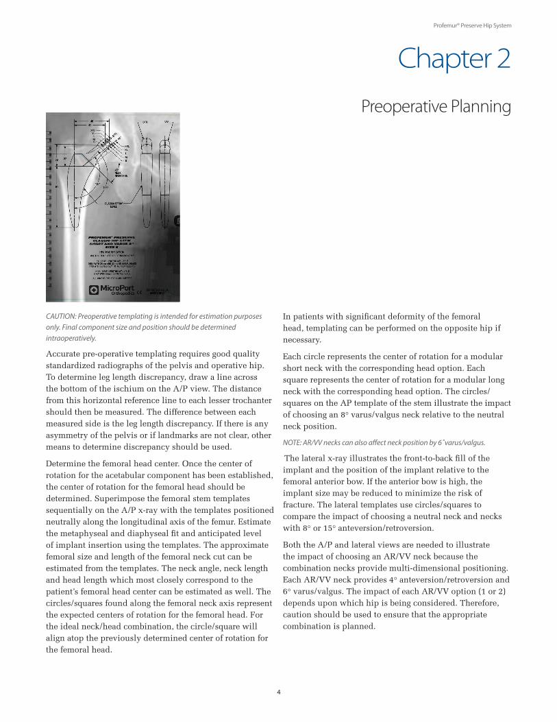
CAUTION: Preoperative templating is intended for estimation purposes only. Final component size and position should be determined intraoperatively.
Accurate pre-operative templating requires good quality standardized radiographs of the pelvis and operative hip. To determine leg length discrepancy, draw a line across the bottom of the ischium on the A/P view. The distance from this horizontal reference line to each lesser trochanter should then be measured. The difference between each measured side is the leg length discrepancy. If there is any asymmetry of the pelvis or if landmarks are not clear, other means to determine discrepancy should be used.
Determine the femoral head center. Once the center of rotation for the acetabular component has been established, the center of rotation for the femoral head should be determined. Superimpose the femoral stem templates sequentially on the A/P x-ray with the templates positioned neutrally along the longitudinal axis of the femur. Estimate the metaphyseal and diaphyseal fit and anticipated level of implant insertion using the templates. The approximate femoral size and length of the femoral neck cut can be estimated from the templates. The neck angle, neck length and head length which most closely correspond to the patient’s femoral head center can be estimated as well. The circles/squares found along the femoral neck axis represent the expected centers of rotation for the femoral head. For the ideal neck/head combination, the circle/square will align atop the previously determined center of rotation for the femoral head.
In patients with significant deformity of the femoral head, templating can be performed on the opposite hip if necessary.
Each circle represents the center of rotation for a modular short neck with the corresponding head option. Each square represents the center of rotation for a modular long neck with the corresponding head option. The circles/squares on the AP template of the stem illustrate the impact of choosing an 8° varus/valgus neck relative to the neutral neck position.
NOTE: AR/VV necks can also affect neck position by 6˚varus/valgus.
The lateral x-ray illustrates the front-to-back fill of the implant and the position of the implant relative to the femoral anterior bow. If the anterior bow is high, the implant size may be reduced to minimize the risk of fracture. The lateral templates use circles/squares to compare the impact of choosing a neutral neck and necks with 8° or 15° anteversion/retroversion.
Both the A/P and lateral views are needed to illustrate the impact of choosing an AR/VV neck because the combination necks provide multi-dimensional positioning. Each AR/VV neck provides 4° anteversion/retroversion and 6° varus/valgus. The impact of each AR/VV option (1 or 2) depends upon which hip is being considered. Therefore, caution should be used to ensure that the appropriate combination is planned.
Preoperative Planning
Chapter 2

Profemur® Preserve Hip System
5
Chapter 3
Femoral Neck Osteotomy Using the greater trochanter or lesser trochanter as a reference, resect the neck at a 45º angle to the longitudinal axis of the femur. The Profemur® Neck Resection Guide (P/N PTRG0410, not included in kit PPREKIT1) is available to help establish the angle of resection.
Open the Femoral Canal Using the Profemur® Box Chisel (P/N PRFS0450), open the femoral canal. The box chisel should be lateralized to ensure a neutral orientation of the implant.
Canal Finder (Optional)Enter the femoral canal with the Profemur® Preserve Canal Finder (P/N 20070186). A machined groove around the middle of the shaft provides the surgeon with the proper
reaming depth. The length of the instrument distal from this groove represents the length of the piloted broaches, while the diameter matches that of the distal pilots on the piloted broaches. The canal finder is designed with a T-handle to avoid over-reaming the canal, to maintain alignment control and to minimize the amount of heat generated during use.
Lateralizing RaspPrepare the metaphyseal region of the femoral canal with the Lateralizing Rasp (P/N 20070185). The shaft of this instrument has aggressive teeth and is curved with a radius between those of the medial and lateral surfaces of the Profemur® Preserve implants.
Surgical Technique
Profemur® Box ChiselP/N PRFS0450
Open the Femoral Canal
Femoral Neck Osteotomy
Profemur® Neck Resection Guide(P/N PTRG0410)
Canal Finder Lateralizing Rasp
Profemur® Preserve® Canal FinderP/N 20070186
Lateralizing RaspP/N 20070185
Profemur® Preserve Hip System
6
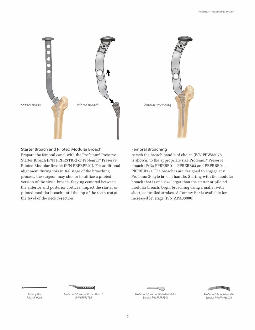
Starter Broach and Piloted Modular BroachPrepare the femoral canal with the Profemur® Preserve Starter Broach (P/N PRPRSTBR) or Profemur® Preserve Piloted Modular Broach (P/N PRPRPB01). For additional alignment during this initial stage of the broaching process, the surgeon may choose to utilize a piloted version of the size 1 broach. Staying centered between the anterior and posterior cortices, impact the starter or piloted modular broach until the top of the teeth rest at the level of the neck resection.
Femoral BroachingAttach the broach handle of choice (P/N PPW38078 is shown) to the appropriate size Profemur® Preserve broach (P/Ns PPREBR01 - PPREBR03 and PRPRBR04 - PRPRBR12). The broaches are designed to engage any Profemur® style broach handle. Starting with the modular broach that is one size larger than the starter or piloted modular broach, begin broaching using a mallet with short, controlled strokes. A Tommy Bar is available for increased leverage (P/N APA00006).
Starter Broach
Profemur® Preserve Starter BroachP/N PRPRSTBR
Profemur® Preserve Piloted Modular Broach P/N PRPRPB01
Piloted Broach
Tommy BarP/N APA0006
Profemur® Broach HandleBroach P/N PPW38078
Femoral Broaching
Profemur® Preserve Hip System
7
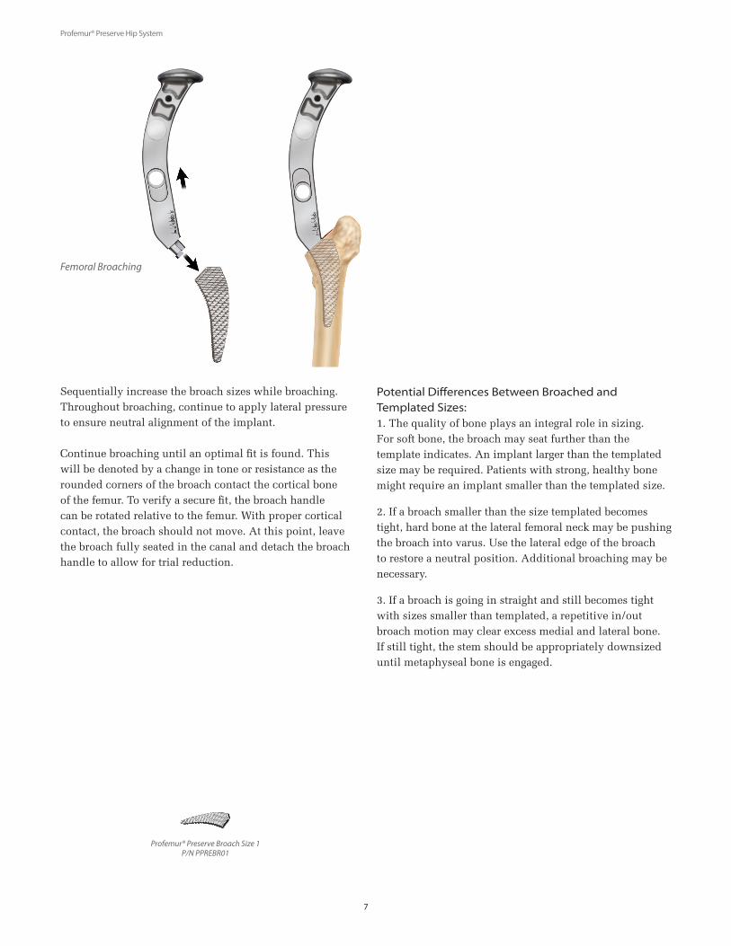
Sequentially increase the broach sizes while broaching. Throughout broaching, continue to apply lateral pressure to ensure neutral alignment of the implant.
Continue broaching until an optimal fit is found. This will be denoted by a change in tone or resistance as the rounded corners of the broach contact the cortical bone of the femur. To verify a secure fit, the broach handle can be rotated relative to the femur. With proper cortical contact, the broach should not move. At this point, leave the broach fully seated in the canal and detach the broach handle to allow for trial reduction.
Potential Differences Between Broached and Templated Sizes:1. The quality of bone plays an integral role in sizing. For soft bone, the broach may seat further than the template indicates. An implant larger than the templated size may be required. Patients with strong, healthy bone might require an implant smaller than the templated size.
2. If a broach smaller than the size templated becomes tight, hard bone at the lateral femoral neck may be pushing the broach into varus. Use the lateral edge of the broach to restore a neutral position. Additional broaching may be necessary.
3. If a broach is going in straight and still becomes tight with sizes smaller than templated, a repetitive in/out broach motion may clear excess medial and lateral bone. If still tight, the stem should be appropriately downsized until metaphyseal bone is engaged.
Profemur® Preserve Broach Size 1P/N PPREBR01
Femoral Broaching
Profemur® Preserve Hip System
8
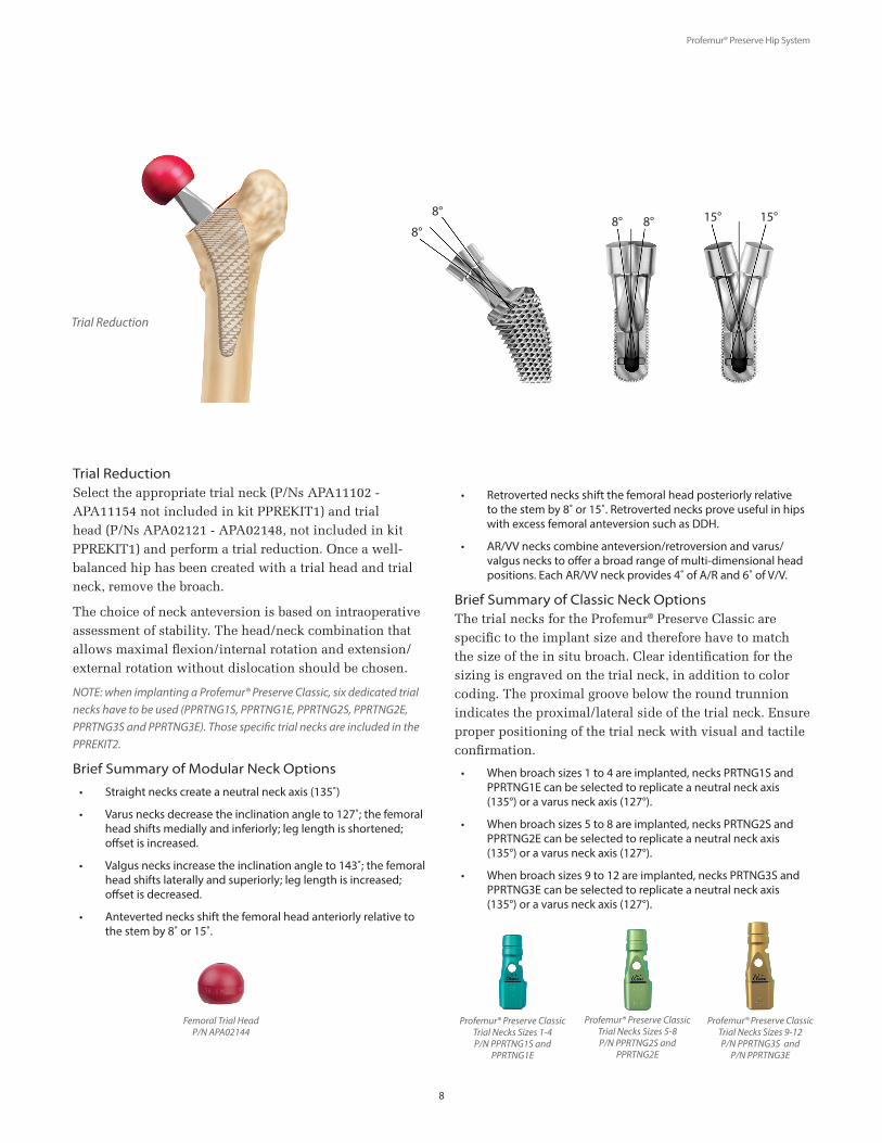
Trial Reduction Select the appropriate trial neck (P/Ns APA11102 -APA11154 not included in kit PPREKIT1) and trial head (P/Ns APA02121 - APA02148, not included in kit PPREKIT1) and perform a trial reduction. Once a well-balanced hip has been created with a trial head and trial neck, remove the broach.
The choice of neck anteversion is based on intraoperative assessment of stability. The head/neck combination that allows maximal flexion/internal rotation and extension/external rotation without dislocation should be chosen.
NOTE: when implanting a Profemur® Preserve Classic, six dedicated trial necks have to be used (PPRTNG1S, PPRTNG1E, PPRTNG2S, PPRTNG2E, PPRTNG3S and PPRTNG3E). Those specific trial necks are included in the PPREKIT2.
Brief Summary of Modular Neck Options
• Straight necks create a neutral neck axis (135˚)
• Varus necks decrease the inclination angle to 127˚; the femoral head shifts medially and inferiorly; leg length is shortened; offset is increased.
• Valgus necks increase the inclination angle to 143˚; the femoral head shifts laterally and superiorly; leg length is increased; offset is decreased.
• Anteverted necks shift the femoral head anteriorly relative to the stem by 8˚ or 15˚.
• Retroverted necks shift the femoral head posteriorly relative to the stem by 8˚ or 15˚. Retroverted necks prove useful in hips with excess femoral anteversion such as DDH.
• AR/VV necks combine anteversion/retroversion and varus/valgus necks to offer a broad range of multi-dimensional head positions. Each AR/VV neck provides 4˚ of A/R and 6˚ of V/V.
Brief Summary of Classic Neck OptionsThe trial necks for the Profemur® Preserve Classic are specific to the implant size and therefore have to match the size of the in situ broach. Clear identification for the sizing is engraved on the trial neck, in addition to color coding. The proximal groove below the round trunnion indicates the proximal/lateral side of the trial neck. Ensure proper positioning of the trial neck with visual and tactile confirmation.
• When broach sizes 1 to 4 are implanted, necks PRTNG1S and PPRTNG1E can be selected to replicate a neutral neck axis (135°) or a varus neck axis (127°).
• When broach sizes 5 to 8 are implanted, necks PRTNG2S and PPRTNG2E can be selected to replicate a neutral neck axis (135°) or a varus neck axis (127°).
• When broach sizes 9 to 12 are implanted, necks PRTNG3S and PPRTNG3E can be selected to replicate a neutral neck axis (135°) or a varus neck axis (127°).
Femoral Trial HeadP/N APA02144
Trial Reduction
Profemur® Preserve Classic Trial Necks Sizes 1-4P/N PPRTNG1S and
PPRTNG1E
Profemur® Preserve Classic Trial Necks Sizes 9-12P/N PPRTNG3S and
P/N PPRTNG3E
8°
8° 15° 15°8° 8°
Profemur® Preserve Classic Trial Necks Sizes 5-8P/N PPRTNG2S and
PPRTNG2E

Profemur® Preserve Hip System
9
Final Stem ImpactorP/N PPF60200
Stem InsertionInsert the femoral implant into the canal by hand and seat it as far as possible. Place the Final Stem Impactor (P/N PPF60200) into the dimple on the proximal face and, using a mallet, fully seat the implant using short, controlled strokes.
Modular Stem Insertion (Optional) Alternatively, the Profemur® Modular Pocket Stem Inserter (P/N PRMOD451) is also included in the Profemur® Preserve instrumentation. The modular pocket stem inserter is designed to fit onto every Profemur® broach handle and engages the modular neck pocket of any Profemur® Stem. Upon impacting forces are translated into the implant at the base of the modular neck pocket, with the black plastic sleeve protecting the inside pocket surfaces.
For the Profemur® Preserve, the implant may sit 1-2 mm more proud than templated due to the additional 0.5mm thickness per side of the plasma. The difference can be addressed during the final trial reduction by selecting the proper head and neck combination.
Final Trial ReductionPerform a final reduction using the trial necks and trial heads to reconfirm stability, range of motion and leg length.
CAUTION: Do not use metal trial necks with the modular implant. Metal trial necks are only to be used with broaches since they may damage the neck taper. Only plastic trial necks (available in PRGIKIT1) should be used for trial reductions with the implant.
Profemur® Modular Pocket Stem InserterP/N PRMOD451
Stem Insertion Final Trial Reduction

Profemur® Preserve Hip System
10
Implant Assembly To properly assemble and impact a Profemur® modular neck, the following procedure is recommended:
STEP A. Suction any fluid from
the stem impact pocket. Ensure
that both the stem and neck are
clean and dry prior to assembly.
STEP B. Insert the oval end of the appropriate femoral neck implant into the femoral stem pocket.
STEP C. Position the leg such that the knee is supported by an assistant on the opposite side of the table. By resting the patient’s knee against the mid-section of the assistant, this will provide counter-force against the mallet blows to ensure the impaction load transfer to the neck junction.
STEP D. Affix the femoral head to the neck. Using the head impactor instrument, strike the impactor with three very firm blows with a mallet to securely fix the head to the neck and stem.
NOTE: If using a ceramic head, securely fix the neck into the stem by impaction, then place the head on the neck by hand, push and turn the head 180˚ to securely lock it in place.
NOTE: If using a Profemur® Classic Stem, affix the femoral head to the stem and impact as instructed.
Profemur® Preserve Hip System
11
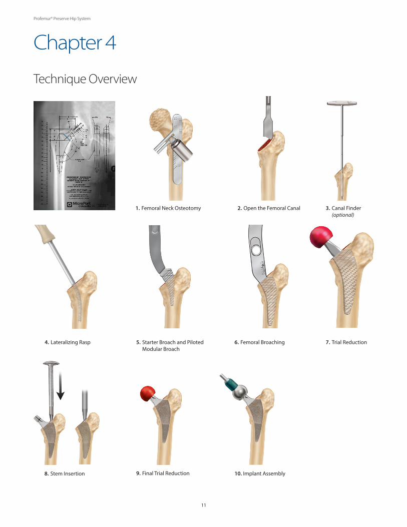
Technique Overview
Chapter 4
1. Femoral Neck Osteotomy
4. Lateralizing Rasp 5. Starter Broach and Piloted Modular Broach
6. Femoral Broaching
8. Stem Insertion
2. Open the Femoral Canal 3. Canal Finder (optional)
7. Trial Reduction
9. Final Trial Reduction 10. Implant Assembly

Profemur® Preserve Hip System
12
STEP ONE: Modular Neck RemovalShould it be necessary, a Profemur® hip stem can be removed in the following manner. The femoral head is removed by placing an osteotome or bone punch on the underside of the femoral head and applying mallet blows upward until the femoral head is removed. With the femoral head removed, thread the 12/14 Adapter (P/N APA00003) over the round taper end of the modular neck. Place the Head/Neck Extractor (P/N APA00001) over the 12/14 adaptor and modular neck and hand tighten the hex end of the shaft until the base of the extractor rests on the stem, while the fork of the extractor rests under the rim of the adaptor.
CAUTION: The base of the extractor must rest on the top surface of the stem’s modular neck pocket, and not on the resected bone.
Attach the Spanner Handle (P/N APA00005) to the hex end of the extractor and rotate clockwise until the neck taper disengages. The Tommy Bar (P/N APA00006) can be inserted into the end of the spanner handle for evengreater leverage.
Please note that these instruments are designed for the purpose of removing a neck during the primary surgery. These instruments may or may not be able to provide the force necessary to disengage a connection between components that have been implanted for a longer period of time. In revision cases, removal and replacement of only the modular neck is contraindicated.
STEP TWO: Stem R emovalThe thread at the base of the modular neck pocket can now be accessed to remove the stem. Insert the Femoral Stem Extractor (P/N PPR67688) into the modular neck pocket and tighten the threaded shaft by hand, firmly seating the shaft via the use of the Hex Screwdriver (P/N PP275400). Using the slide hammer, create extraction forces onto the underside of the shaft using repetitive upward blows to remove the stem. If bone on-growth exists, it may be necessary to use osteotomes in order to first disengage the stem/bone interface.
Spanner Handle P/N APA00005
Head/Neck Extractor P/N APA00001
12/14 Adapter P/N APA00003
Tommy Bar P/N APA00006
Hex Screwdriver P/N PP275400
Femoral Stem ExtractorP/N PPR67688
Femoral Stem Removal - Modular Option
Profemur® Preserve Hip System
13
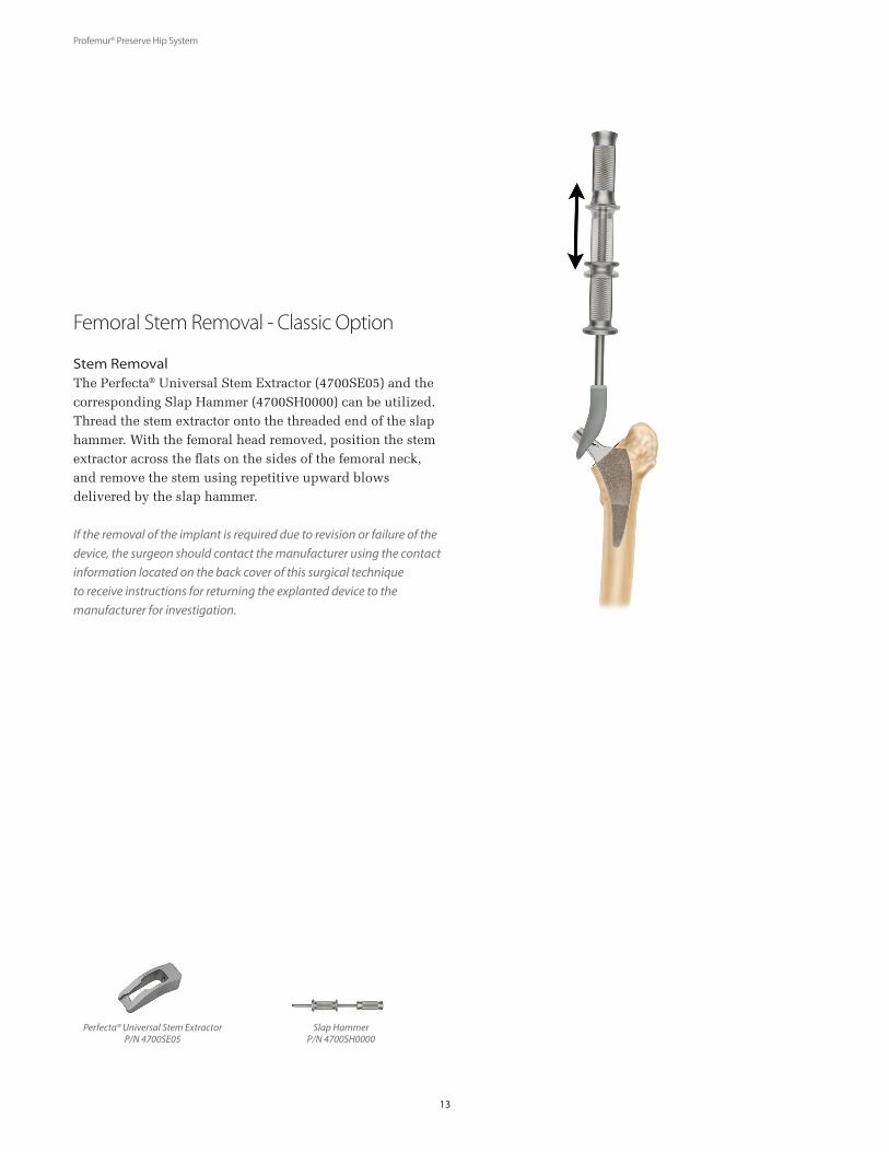
Stem RemovalThe Perfecta® Universal Stem Extractor (4700SE05) and the corresponding Slap Hammer (4700SH0000) can be utilized. Thread the stem extractor onto the threaded end of the slap hammer. With the femoral head removed, position the stem extractor across the flats on the sides of the femoral neck, and remove the stem using repetitive upward blows delivered by the slap hammer.
If the removal of the implant is required due to revision or failure of the device, the surgeon should contact the manufacturer using the contact information located on the back cover of this surgical technique to receive instructions for returning the explanted device to the manufacturer for investigation.
Femoral Stem Removal - Classic Option
Perfecta® Universal Stem ExtractorP/N 4700SE05
Slap HammerP/N 4700SH0000

Profemur® Preserve Hip System
14
Ordering Information
Chapter 5
Profemur® Preserve Classic StemsPPREKITB Catalog No. Description Stem Size
PPRCLS01 Classic Straight Stem 1
PPRCLS02 Classic Straight Stem 2
PPRCLS03 Classic Straight Stem 3
PPRCLS04 Classic Straight Stem 4
PPRCLS05 Classic Straight Stem 5
PPRCLS06 Classic Straight Stem 6
PPRCLS07 Classic Straight Stem 7
PPRCLS08 Classic Straight Stem 8
PPRCLS09 Classic Straight Stem 9
PPRCLS10 Classic Straight Stem 10
PPRCLS11 Classic Straight Stem 11
PPRCLS12 Classic Straight Stem 12
PPRCLE01 Classic Varus 8˚Stem 1
PPRCLE02 Classic Varus 8˚Stem 2
PPRCLE03 Classic Varus 8˚Stem 3
PPRCLE04 Classic Varus 8˚Stem 4
PPRCLE05 Classic Varus 8˚Stem 5
PPRCLE06 Classic Varus 8˚Stem 6
PPRCLE07 Classic Varus 8˚Stem 7
PPRCLE08 Classic Varus 8˚Stem 8
PPRCLE09 Classic Varus 8˚Stem 9
PPRCLE10 Classic Varus 8˚Stem 10
PPRCLE11 Classic Varus 8˚Stem 11
PPRCLE12 Classic Varus 8˚Stem 12
Profemur® Preserve Classic Trial Necks Kit PPREKIT2
Catalog No. Description
PPRTNG1S Classic Trial Necks sizes 1-4 Straight
PPRTNG1E Classic Trial Necks sizes 1-4 Varus 8°
PPRTNG2S Classic Trial Necks sizes 5-8 Straight
PPRTNG2E Classic Trial Necks sizes 5-8 Varus 8°
PPRTNG3S Classic Trial Necks sizes 9-12 Straight
PPRTNG3E Classic Trial Necks sizes 9-12 Varus 8°
PPRECAD1 Classic Trial Necks Caddy
Profemur® Preserve Hip System
15
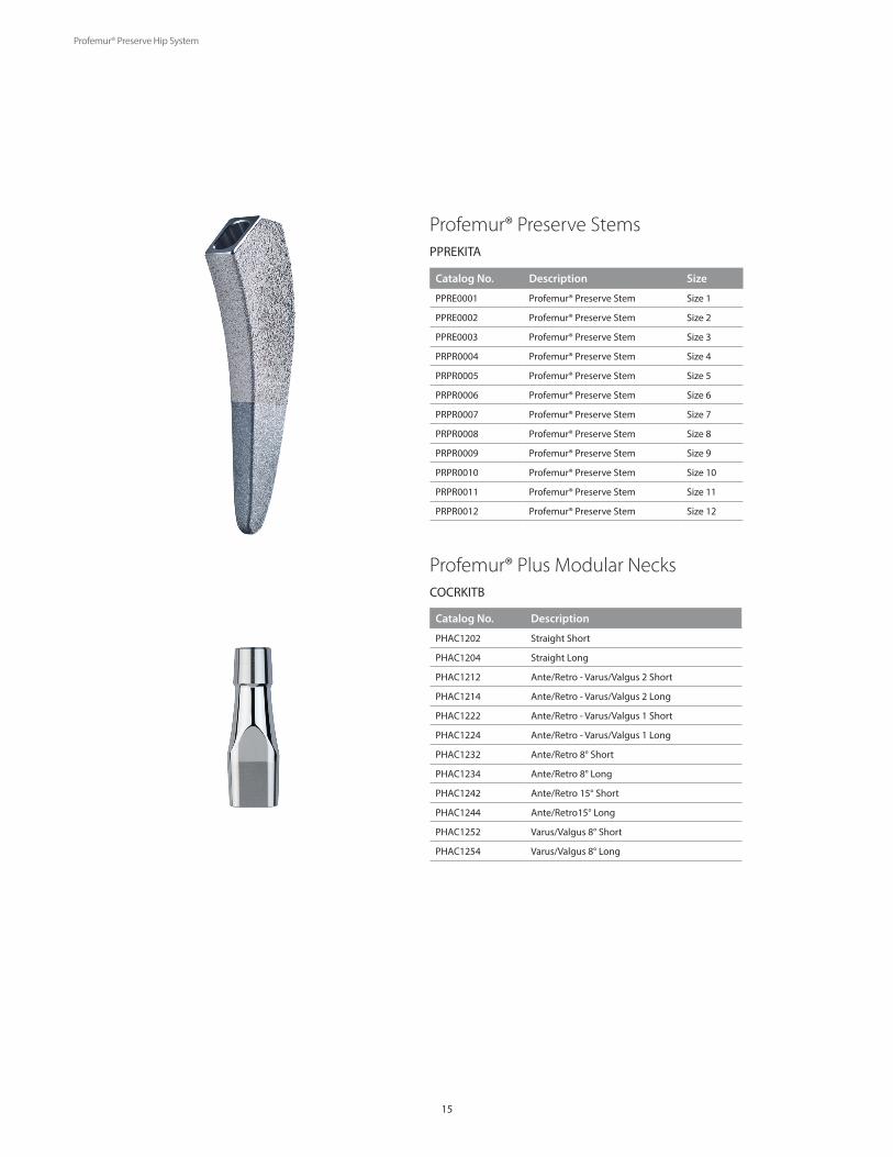
Profemur® Plus Modular NecksCOCRKITB
Profemur® Preserve StemsPPREKITA
Catalog No. Description Size
PPRE0001 Profemur® Preserve Stem Size 1
PPRE0002 Profemur® Preserve Stem Size 2
PPRE0003 Profemur® Preserve Stem Size 3
PRPR0004 Profemur® Preserve Stem Size 4
PRPR0005 Profemur® Preserve Stem Size 5
PRPR0006 Profemur® Preserve Stem Size 6
PRPR0007 Profemur® Preserve Stem Size 7
PRPR0008 Profemur® Preserve Stem Size 8
PRPR0009 Profemur® Preserve Stem Size 9
PRPR0010 Profemur® Preserve Stem Size 10
PRPR0011 Profemur® Preserve Stem Size 11
PRPR0012 Profemur® Preserve Stem Size 12
Catalog No. Description
PHAC1202 Straight Short
PHAC1204 Straight Long
PHAC1212 Ante/Retro - Varus/Valgus 2 Short
PHAC1214 Ante/Retro - Varus/Valgus 2 Long
PHAC1222 Ante/Retro - Varus/Valgus 1 Short
PHAC1224 Ante/Retro - Varus/Valgus 1 Long
PHAC1232 Ante/Retro 8° Short
PHAC1234 Ante/Retro 8° Long
PHAC1242 Ante/Retro 15° Short
PHAC1244 Ante/Retro15° Long
PHAC1252 Varus/Valgus 8° Short
PHAC1254 Varus/Valgus 8° Long
Profemur® Preserve Hip System
16
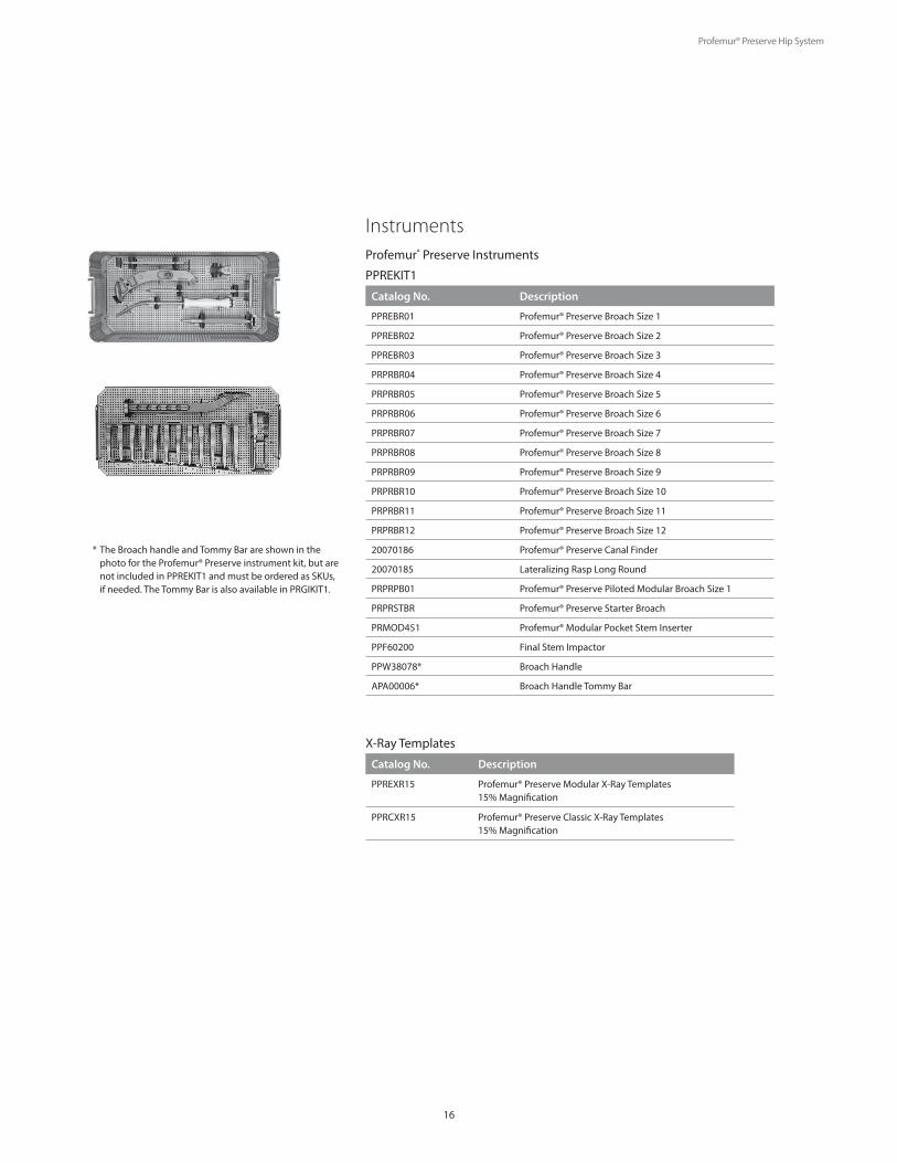
Profemur® Preserve Instruments
PPREKIT1
Catalog No. Description
PPREBR01 Profemur® Preserve Broach Size 1
PPREBR02 Profemur® Preserve Broach Size 2
PPREBR03 Profemur® Preserve Broach Size 3
PRPRBR04 Profemur® Preserve Broach Size 4
PRPRBR05 Profemur® Preserve Broach Size 5
PRPRBR06 Profemur® Preserve Broach Size 6
PRPRBR07 Profemur® Preserve Broach Size 7
PRPRBR08 Profemur® Preserve Broach Size 8
PRPRBR09 Profemur® Preserve Broach Size 9
PRPRBR10 Profemur® Preserve Broach Size 10
PRPRBR11 Profemur® Preserve Broach Size 11
PRPRBR12 Profemur® Preserve Broach Size 12
20070186 Profemur® Preserve Canal Finder
20070185 Lateralizing Rasp Long Round
PRPRPB01 Profemur® Preserve Piloted Modular Broach Size 1
PRPRSTBR Profemur® Preserve Starter Broach
PRMOD451 Profemur® Modular Pocket Stem Inserter
PPF60200 Final Stem Impactor
PPW38078* Broach Handle
APA00006* Broach Handle Tommy Bar
X-Ray Templates
Catalog No. Description
PPREXR15 Profemur® Preserve Modular X-Ray Templates 15% Magnification
PPRCXR15 Profemur® Preserve Classic X-Ray Templates15% Magnification
Instruments
* The Broach handle and Tommy Bar are shown in the photo for the Profemur® Preserve instrument kit, but are not included in PPREKIT1 and must be ordered as SKUs, if needed. The Tommy Bar is also available in PRGIKIT1.

Profemur® Preserve Hip System
17
PRGIKIT1
Profemur® Standard Instrument Kit
Catalog No. Description
APA02121 Femoral Head Trial 28mm Short -3.5mm
APA02122 Femoral Head Trial 28mm Medium +0
APA02123 Femoral Head Trial 28mm Long +3.5mm
APA02124 Femoral Head Trial 28mm Extra Long +7mm
APA02125 Femoral Head Trial 28mm XX-Long +10.5mm
APA02142 Femoral Head Trial 36mm S (-3.5)
APA02144 Femoral Head Trial 36mm M (0)
APA02146 Femoral Head Trial 36mm L (+3.5)
APA02148 Femoral Head Trial 36mm XL (+7)
APA02151 Femoral Head Trial 32mm Short -3.5mm
APA02152 Femoral Head Trial 32mm Medium +0mm
APA02153 Femoral Head Trial 32mm Long +3.5mm
APA02154 Femoral Head Trial 32mm X-Long +7mm
APA00001 Head/Neck Extractor
APA00005 Cardan Spanner Hex.14
APA00006 Tommy Bar for Cardan Spanner
APA00003 Adaptor 12/14
PPR67688 Extractor For ANCA-FIT™ Stem
PRFS0462 Profemur® Broach Extraction
PP275400 Hex Screwdriver
PRFS0450 Profemur® S & Tapered Stem
4400FI0000 Femoral Head Impactor
K0001016 Advance® Quick Disconnect
PRFS0451 Profemur® S Tissue Protecting
APA04750 Profemur® E Initial Reamer
APA04244 Straight Broach Handle
APA04241 Profemur® MIS Broach Handle
20070050 Modular Neck Inserter
PRFS1461 Profemur® Threaded In Line
PRFS0460 Profemur® Screwdriver Inserter
APA11102 Profemur® Short Straight Trial Neck Radio Opaque Radel
APA11104 Profemur® Long Straight Trial Neck Radio Opaque Radel
APA11112 Profemur® Short A/R VAR/VAL 1 Trial Neck Radio Opaque Radel
APA11114 Profemur® Long A/R VAR/VAL 1 Trial Neck Radio Opaque Radel
APA11122 Profemur® Short A/R VAR/VAL 2 Trial Neck Radio Opaque Radel
APA11124 Profemur® Long A/R VAR/VAL 2 Trial Neck Radio Opaque Radel
APA11132 Profemur® Short A/R 8DG Trial Neck Radio Opaque Radel
APA11134 Profemur® Long A/R 8DG Trial Neck Radio Opaque Radel
APA11142 Profemur® Short A/R 15DG Trial Neck Radio Opaque Radel
APA11144 Profemur® Long A/R 15DG Trial Neck Radio Opaque Radel
APA11152 Profemur® Short VAR/VAL 8DG Trial Neck Radio Opaque Radel
APA11154 Profemur® Long VAR/VAL 8DG Trial Neck Radio Opaque Radel
PRGITRAY Profemur® S/T Tray & Lid General Instrument
PREXTRAY Profemur® S/T Tray & Lid Extraction
Profemur® General Instruments
Profemur® Preserve Hip System
18
Chapter 6Indications and Warnings
Intended UseMicroPort total hip systems are intended for use in total hip arthroplasty for reduction or relief of pain and/or improved hip function in skeletally mature patients.Indications for Use: 1) non-inflammatory degenerative joint disease such as osteoarthritis, avascular necrosis, ankylosis, protrusio acetabuli, and painful hip dysplasia; 2) inflammatory degenerative joint disease such as rheumatoid arthritis; 3) correction of functional deformity; and, 4) revision procedures where other treatments or devices have failedRough grit blast surfaces and the titanium plasma spray coatings applied to implant surfaces are intended for uncemented arthroplasty.
ContraindicationsPatients should be warned of these contraindications.Contraindications include: 1) overt infection; 2) distant foci of infections (which may cause hematogenous spread to the implant site); 3) rapid disease progression as manifested by joint destruction or bone absorption apparent on roentgenogram; 4) skeletally immature patients (patient is less than 21 years of age at the time of surgery); 5) cases where there is inadequate neuromuscular status (e.g., prior paralysis, fusion and/or inadequate abductor strength), poor bone stock, poor skin coverage around the joint which would make the procedure unjustifiable; 6) neuropathic joints; 7) hepatitis or HIV infection; 8) neurological or musculoskeletal disease that may adversely affect gait or weight-bearing.
Additional contraindications for a metal-on-metal bearing include (Not available in U.S. or Canada): 1) Patients with known moderate to severe renal insufficiency; 2) Females of childbearing age are contraindicated due to the unknown effects of elevated levels of metal ions on the fetus.
Product-Specific Warnings and Precautions Do not attempt to seat the implant beyond the envelope of femoral bone preparation. Forcing to seat the implant beyond the prepared femoral bone may increase the chance of bone fracture. In some cases, a portion of the proximal body with or without coating may be visible above the proximal resection level.
The smaller sized femoral implants are intended for patients with narrower intramedullary femoral canals. The geometry of these implants is reduced to accommodate the anatomy of the
narrower intramedullary femoral canal, which also decreases the fatigue-strength and load-bearing characteristics of the implant.
Other Modular Components (Femoral Head and Stems, Modular Necks and Proximal Body).Scratching of femoral heads, modular necks and proximal and distal stem tapers should be avoided. Repeated assembly and disassembly of these components could compromise the locking action of the taper joint. Prior to assembly, surgical debris must be cleaned from the interior of the female seat of the proximal body to ensure proper locking. Ensure components are firmly seated to prevent disassociation. The femoral head, neck taper of the femoral component, modular neck tapers, body taper, female seat of the proximal body must be clean and dry before assembly. Do not resterilize femoral prostheses with ceramic femoral heads seated on the stem. Please refer to the content below for specific warnings and precautions regarding ceramic femoral heads.
Compatible Modular Femoral Heads Stems and modular necks with the MicroPort 12/14 SLT Taper should only be used in combination with femoral heads with the MicroPort 12/14 SLT Taper. Cobalt chrome femoral heads with the MicroPort 12/14 SLT Taper are designed for use with cobalt-chromium-molybdenum, titanium alloy and ISO 5832-9 stainless steel (not available in the U.S. or Canada) femoral components with the MicroPort 12/14 SLT Taper.
The neck/body component or neck/femoral stem should be changed only when clinically necessary. Refer to proper neck extraction technique in the surgical technique.
Modular Necks• Cobalt Chrome Modular Necks are not for use with the following devices: o Alumina (Biolox Forte) “Ceramic Femoral Head” (size 28mm Long)• Profemur® Preserve Stems are only intended for use with cobalt chrome modular necks.
The potential long-term biological effects of metal wear debris and metal ion production are not known. Questions regarding carcinogenicity have been raised in literature; no studies have conclusive evidence that metal wear debris or metal ions are carcinogenic.
IMPORTANTPrior to use of the system, the surgeon should refer to the product package insert for additional warnings, precautions, indications, contraindications and adverse effects. Instructions For Use package inserts are also available by contacting the manufacturer. Contact information can be found on the back of this Surgical Technique and the Instructions For Use package inserts are available on the website listed.

Trademarks and Registered marks of MicroPort Orthopedics Inc.© 2015 MicroPort Orthopedics Inc. All Rights Reserved. 010984_Jun15
The CE-Marking of Conformity is applied per catalog number and appears on the outer package label, if applicable.
MicroPort Orthopedics Inc.5677 Airline RoadArlington, TN USA 38002866 872 0211
ortho.microport.com
MicroPort Orthopedics BVHoogoorddreef 51101 BA AmsterdamThe Netherlands+31 20 545 01 00
EC REP
Jürg Aebi, MDClinique du Pont de ChaumeMontauban, France
Martin Lavigne, MDMaisonneuve-Rosemont HospitalMontreal, Quebec
Pascal-André Vendittoli, MDMaisonneuve-Rosemont HospitalMontreal, Quebec
Prof. Dr. Pavel DufekClinic for Orthopedics and Ortho RehabilitationNeustadt, Germany
Ryan Nunley, MDWashington UniversitySt. Louis, Missouri
Sonny Bal, MDUniversity of MissouriColumbia, Missouri