prof-kotel.ru* da montare a cura dell'installatore. legenda prima di montare la flangia,...
TRANSCRIPT


K 6/MK 7/M
073515_1_31A
BRUCIATORI MISTI DI GAS/GASOLIO BISTADIO PROGRESSIVI O MODULANTI_SERIE KTWO STAGES PROGRESSIVE OR MODULATING BURNERS DUAL FUEL GAS/LIGHT-OIL_K SERIESQUEMADORES DUALES GAS/GASÓLEO 2 LLAMAS PROGRESIVOS O MODULANTES_SERIE K
I
GB
E
ALLEGATO PER VERSIONI _3xATTACHED FOR VERSIONS _3xADJUNTO PARA VERSIÓNES _3x
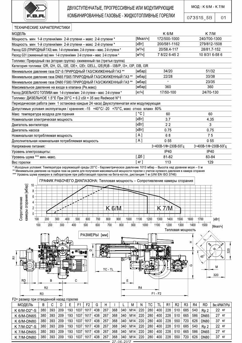
CARATTERISTICHE TECNICHE/TECHNICAL CHARACTERISTICS/ESPECIFICACIONES TÉCNICAS
1
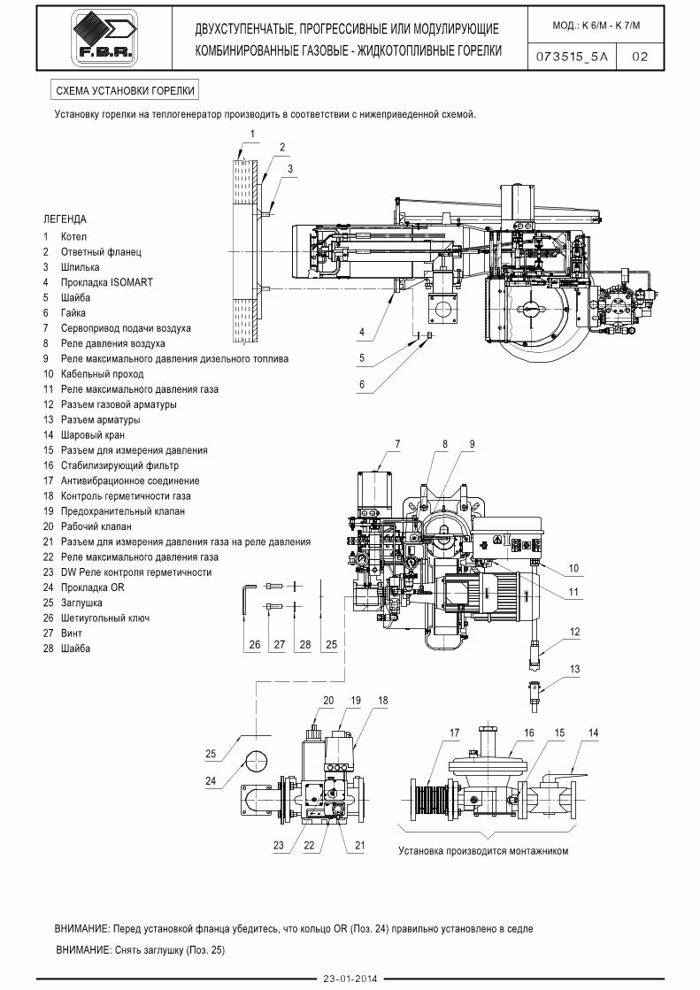
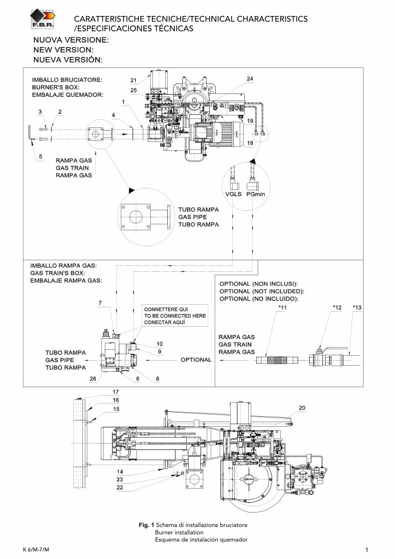
Fig. 1 Schema di installazione bruciatore Burner installation Esquema de instalación quemador
K 6/M-7/M
K 6/M-7/M
CARATTERISTICHE TECNICHE/TECHNICAL CHARACTERISTICS/ESPECIFICACIONES TÉCNICAS
2
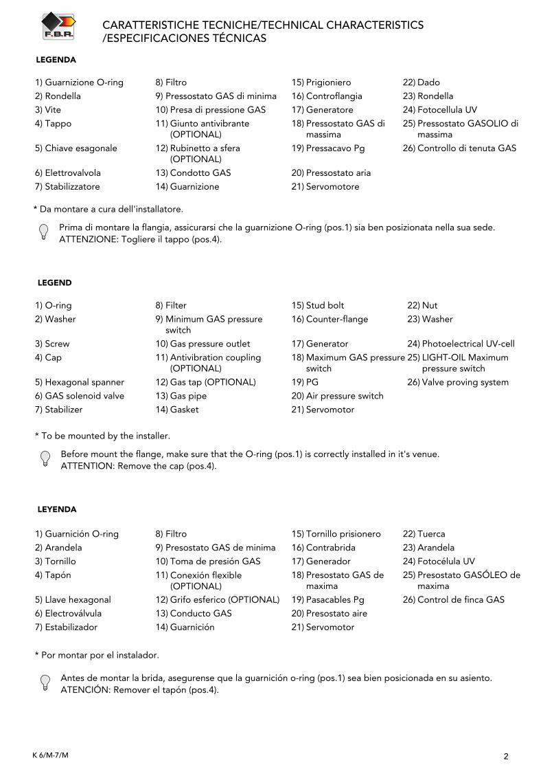
* Da montare a cura dell'installatore.
LEGENDA
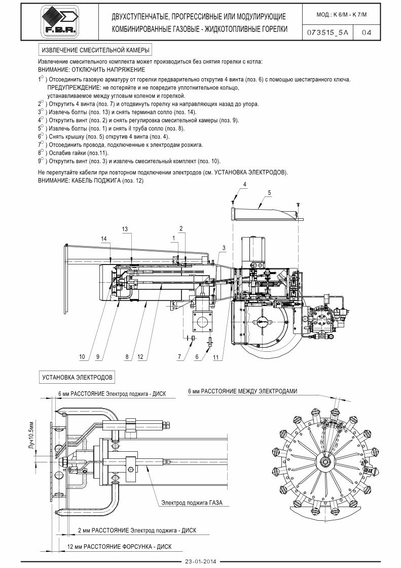
Prima di montare la flangia, assicurarsi che la guarnizione O-ring (pos.1) sia ben posizionata nella sua sede.ATTENZIONE: Togliere il tappo (pos.4).
* To be mounted by the installer.
LEGEND
Before mount the flange, make sure that the O-ring (pos.1) is correctly installed in it's venue. ATTENTION: Remove the cap (pos.4).
* Por montar por el instalador.
LEYENDA
Antes de montar la brida, asegurense que la guarnición o-ring (pos.1) sea bien posicionada en su asiento.ATENCIÓN: Remover el tapón (pos.4).
1) Guarnizione O-ring
2) Rondella
3) Vite
4) Tappo
5) Chiave esagonale
6) Elettrovalvola
7) Stabilizzatore
8) Filtro
9) Pressostato GAS di minima
10) Presa di pressione GAS
11) Giunto antivibrante (OPTIONAL)
12) Rubinetto a sfera (OPTIONAL)
13) Condotto GAS
14) Guarnizione
15) Prigioniero
16) Controflangia
17) Generatore
18) Pressostato GAS dimassima
19) Pressacavo Pg
20) Pressostato aria
21) Servomotore
22) Dado
23) Rondella
24) Fotocellula UV
25) Pressostato GASOLIO di massima
26) Controllo di tenuta GAS
1) O-ring
2) Washer
3) Screw
4) Cap
5) Hexagonal spanner
6) GAS solenoid valve
7) Stabilizer
8) Filter
9) Minimum GAS pressureswitch
10) Gas pressure outlet
11) Antivibration coupling(OPTIONAL)
12) Gas tap (OPTIONAL)
13) Gas pipe
14) Gasket
15) Stud bolt
16) Counter-flange
17) Generator
18) Maximum GAS pressureswitch
19) PG
20) Air pressure switch
21) Servomotor
22) Nut
23) Washer
24) Photoelectrical UV-cell
25) LIGHT-OIL Maximum pressure switch
26) Valve proving system
1) Guarnición O-ring
2) Arandela
3) Tornillo
4) Tapón
5) Llave hexagonal
6) Electroválvula
7) Estabilizador
8) Filtro
9) Presostato GAS de minima
10) Toma de presión GAS
11) Conexión flexible (OPTIONAL)
12) Grifo esferico (OPTIONAL)
13) Conducto GAS
14) Guarnición
15) Tornillo prisionero
16) Contrabrida
17) Generador
18) Presostato GAS de maxima
19) Pasacables Pg
20) Presostato aire
21) Servomotor
22) Tuerca
23) Arandela
24) Fotocélula UV
25) Presostato GASÓLEO de maxima
26) Control de finca GAS

SISTEMA ELETTRICO/ELECTRICAL SYSTEM/SISTEMA ELÉCTRICO
K 6/M-7/M
ELECTRICAL SYSTEM
3
ELECTRICAL PANEL LAYOUT
Please refer to elctrical panel layout supplied with the present instructions.
WORKING DIAGRAM OF THE ELECTRICAL DEVICE
Please refer to electrical device handbook supplied with the present Instructions.
ELECTRICAL CONNECTIONS TO THE GAS TRAIN
For the electrical connections to the gas train, please refer to the following photo and to the electrical panel layoutsupplied with the present instructions.
Connessione elettrica rampa gas/Electrical connections to the gas train/Conexiones eléctricas del rampa de gas
SCHEMA ELETTRICO
Fare riferimento allo schema elettrico fornito a corredo del presente MANUALE.
DIAGRAMMA DI FUNZIONAMENTO DELL'APPARECCHIATURA
Si rinvia a quanto esposto nell'opuscolo dell'apparecchiatura che accompagna il presente manuale.
CONNESSIONE ELETTRICA RAMPA GAS
Per le connessioni elettriche alla rampa gas, fare riferimento alla foto seguente e allo schema elettrico fornito a corredodel presente MANUALE.
ESQUEMA ELÉCTRICO
Consulte el esquema eléctrico suministrado con este MANUAL.
DIAGRAMA DE FUNCIONAMIENTO DEL EQUIPO
Por favor, consulte las instrucciones del programador del quemador que acompaña a este manual.
CONEXIONES ELÉCTRICAS DEL RAMPA DE GAS
Para las conexiones eléctricas del rampa de gas, consulte la fotografía siguiente y consulte el esquema eléctricosuministrado con este MANUAL.

Le illustrazioni e i dati riportati sono indicativi. F.B.R. Bruciatori S.r.l. si riserva il diritto di apportare, senza obbligo di preavviso, tutte le modifiche opportune, per l'evoluzione dei propri prodotti. The illustrations and data here shown are indicative. F.B.R. Bruciatori S.r.l. reserves the right to bring, without any obligation of warning, any changes that would be appropriate to the continuing development of their products.Las ilustraciones y los datos presentados son indicativos. Estando F.B.R. Bruciatori S.r.l. constantemente comprometida en el perfeccionamiento de la producción, se reserva el derecho de aportar, sin preaviso, modificaciones.
F.B.R. Bruciatori S.r.l.Via V. Veneto, 152 _ 37050 Angiari (VR) _ ItalyTel. +39 0442 97000 _ Fax + 39 0442 97299www. fbr.it _ email: [email protected]