productmanual comforttouch v1.0 en dynamic · pdf file6.1 installing the comfort panel ip...
TRANSCRIPT

Product manual Busch-ComfortTouch
Busch-ComfortTouch
www.BUSCH-JAEGER.de

2/240
Table of contents
Table of contents ...........................................................................................1-2
1 Product description.......................................................................1-14
2 Technical specification Dimensions...............................................2-15 2.1 Dimensions ....................................................................................... 2-15 2.2 Technical data of the Busch-ComfortTouch .......................................... 2-17 2.3 Connection diagram ........................................................................... 2-17
3 Colour concept Busch-priOn .........................................................3-18
4 Range of functions of the Busch-ComfortTouch.............................4-19 4.1 Operating functions ............................................................................ 4-19 4.2 Room temperature control .................................................................. 4-19 4.3 Time / Date Display ............................................................................ 4-20 4.4 Image messages................................................................................ 4-20 4.5 Voice messages ................................................................................ 4-21 4.6 Scenes and sequences ...................................................................... 4-22 4.7 Weekly programs ............................................................................... 4-23 4.8 Presence simulation ........................................................................... 4-24 4.9 Access control ................................................................................... 4-25 4.10 Malfunction and alarm display ............................................................. 4-25 4.11 Message centre ................................................................................. 4-26 4.12 A/V surveillance ................................................................................. 4-26 4.13 Media-Player ..................................................................................... 4-27 4.14 Electronic picture frame ...................................................................... 4-27 4.15 E-mails.............................................................................................. 4-28 4.16 Feed reader....................................................................................... 4-28 4.17 Short-period timer (egg timer).............................................................. 4-29 4.18 Alarm clock........................................................................................ 4-29 4.19 Remote maintenance ......................................................................... 4-30 4.20 Remote operation .............................................................................. 4-30 4.21 IR remote control ............................................................................... 4-31 4.22 Web interface .................................................................................... 4-31 4.23 Keylock (cleaning lock) ....................................................................... 4-31
5 Operating concept ........................................................................5-31 5.1 Status bar.......................................................................................... 5-32 5.2 Navigation bar ................................................................................... 5-32 5.3 Busch-ComfortTouch page types......................................................... 5-33 5.3.1 Start page functions ........................................................................... 5-33 5.3.2 Start page with floor plan .................................................................... 5-34 5.3.3 Operating page functions .................................................................... 5-34 5.3.4 Operating pages with image of room.................................................... 5-36 5.3.5 Application page ................................................................................ 5-37
6 Busch Control Panel software .......................................................6-37 6.1 Installing the Comfort Panel IP Project software.................................... 6-37 6.1.1 Hardware requirements ...................................................................... 6-37 6.1.2 Installation sequence of the IP Project software .................................... 6-38 6.2 Installation of the Busch Comfort Panel ETS3 macro............................. 6-41 6.2.1 Prerequisite ....................................................................................... 6-41

3/240
6.2.2 Installation sequence .......................................................................... 6-42 6.2.3 Integration of the Busch Comfort Panel in the ETS3 .............................. 6-42
7 Comfort Panel IP Project software..................................................7-42 7.1 Recommended sequence of a project planning ..................................... 7-42 7.2 Screen areas in IP Project................................................................... 7-44 7.3 Operating the IP Project software ........................................................ 7-46 7.3.1 Copying a project ............................................................................... 7-46 7.3.2 Moving/copying pages and operating elements ..................................... 7-46 7.3.3 Cross references................................................................................ 7-46 7.3.4 Consistency check ............................................................................. 7-46 7.4 Downloading project into panel ............................................................ 7-47
8 Getting started - a first project .......................................................8-48 8.1 Project start ....................................................................................... 8-48 8.2 Importing of group addresses .............................................................. 8-48 8.3 Configuring the Busch Comfort Panel................................................... 8-49 8.4 Navigation structure ........................................................................... 8-50 8.5 Configuring the operating pages (functions).......................................... 8-51 8.6 Start page with floor plan or room image .............................................. 8-55 8.6.1 Operating pages with floor plan or room view........................................ 8-58 8.7 Operating pages with small image of room ........................................... 8-60 8.8 Integration of applications ................................................................... 8-61
Advice 8-63
9 Logic functions.............................................................................9-63 9.1.1 Using logic functions........................................................................... 9-63 9.1.2 Creating logic functions....................................................................... 9-64 9.1.2.1 Creating logic functions....................................................................... 9-64 9.1.2.2 Placing and configuring logic modules .................................................. 9-64 9.1.2.3 Linking logic modules with each other .................................................. 9-65 9.1.2.4 Creating feed-back loops..................................................................... 9-65 9.1.3 Available logic modules ....................................................................... 9-65 9.1.3.1 Input and output modules................................................................... 9-65 9.1.3.2 Boolean logic modules ........................................................................ 9-66 9.1.3.3 Comparator........................................................................................ 9-66 9.1.3.4 Algebraic logic modules....................................................................... 9-67 9.1.3.5 Additional mathematical logic modules ................................................. 9-68 9.1.3.6 Signal control logic modules ................................................................ 9-68 9.1.3.7 Logic modules for signal generation ..................................................... 9-69 9.1.3.8 Logic modules for time and date.......................................................... 9-69
10 Help topics .................................................................................10-70 10.1 Help pages in this chapter ................................................................. 10-70
11 IP-Project fundamentals ...........................................................11-71 11.1 Help pages in this chapter ................................................................. 11-71
12 Properties of the Busch Comfort Panel......................................12-71 12.1 → Comfort Panel page types ............................................................. 12-72 12.1.1 The start page ................................................................................. 12-72 12.1.2 Operating pages............................................................................... 12-72 12.1.3 Application pages ............................................................................. 12-73
4/240
12.2 → Navigation in the Comfort Panel .................................................... 12-73 12.2.1 Navigation bar function..................................................................... 12-73 12.2.2 Layout of the navigation bar.............................................................. 12-73 12.3 → Applications and modules in the Comfort Panel............................... 12-73 12.3.1 Applications ..................................................................................... 12-73 12.3.1.1 Multimedia....................................................................................... 12-73 12.3.1.2 News............................................................................................... 12-74 12.3.1.3 Telephony........................................................................................ 12-74 12.3.1.4 Home control ................................................................................... 12-74 12.3.1.5 Security ........................................................................................... 12-74 12.3.1.6 Tools............................................................................................... 12-74 12.3.1.7 Einstellungen ................................................................................... 12-74 12.3.2 Software modules............................................................................. 12-75 12.4 → Comfort Panel design ................................................................... 12-75
13 General operation of IP-Project ................................................13-76 13.1 → Areas in IP-Project ....................................................................... 13-76 13.1.1 Library area ..................................................................................... 13-76 13.1.1.1 Overview section .............................................................................. 13-76 13.1.1.2 Elements section .............................................................................. 13-76 13.1.1.3 Actions section ................................................................................. 13-77 13.1.2 Working area ................................................................................... 13-77 13.1.2.1 Clipboard ......................................................................................... 13-77 13.1.2.2 Control Elements tab ........................................................................ 13-77 13.1.2.3 Objects tab ...................................................................................... 13-78 13.1.3 Parameter area ................................................................................ 13-79 13.1.4 Help area......................................................................................... 13-79 13.1.4.1 Help section..................................................................................... 13-79 13.1.4.2 Consistency Check section................................................................. 13-80 13.2 → Levels in IP-Project ...................................................................... 13-80 13.2.1 Project level:.................................................................................... 13-80 13.2.2 Navigation level: .............................................................................. 13-81 13.2.3 Page level:....................................................................................... 13-81 13.3 → Navigation in IP-Project ................................................................ 13-81 13.3.1 Navigate between levels ................................................................... 13-81 13.3.2 Navigate to other elements ............................................................... 13-82 13.3.2.1 13-82 13.3.3 Navigating via keypad....................................................................... 13-82 13.4 → The context menu........................................................................ 13-83
14 Add and edit elements...............................................................14-83 14.1 → Add elements from the library ....................................................... 14-84 14.1.1 Available elements............................................................................ 14-84 14.1.1.1 Project level:.................................................................................... 14-84 14.1.1.2 Navigation level: .............................................................................. 14-84 14.1.1.3 Page level:....................................................................................... 14-84 14.1.2 Using Drag and Drop to add.............................................................. 14-85 14.2 → Select (mark) elements................................................................. 14-85 14.2.1 Use and purpose of selecting............................................................. 14-85 14.2.2 Select several elements..................................................................... 14-85 14.3 → Move elements ............................................................................ 14-87 14.4 → Cut, copy, paste elements............................................................. 14-87

5/240
14.4.1 Cut.................................................................................................. 14-87 14.4.2 Copy ............................................................................................... 14-88 14.4.3 Paste (from the Windows clipboard)................................................... 14-88 14.5 → Rename elements ........................................................................ 14-89 14.6 → Deleting elements ........................................................................ 14-89 14.7 → Change element symbols .............................................................. 14-90 14.8 → Change element parameters ......................................................... 14-90
15 Use Help.....................................................................................15-91 15.1 → Use help area in IP-Project............................................................ 15-91 15.1.1 Open help area ................................................................................ 15-91 15.1.2 Use Help in the help area .................................................................. 15-91 15.2 → Use this help system..................................................................... 15-92 15.2.1 Contents of the help system .............................................................. 15-92 15.2.2 Find the right help page .................................................................... 15-92 15.2.2.1 About the table of contents ............................................................... 15-92 15.2.2.2 About links in the help pages............................................................. 15-92 15.2.2.3 About the help system search function ............................................... 15-93 15.2.2.4 About the context menu in IP-Project................................................. 15-93 15.2.3 Use bookmarks................................................................................. 15-94 15.2.3.1 Create bookmark.............................................................................. 15-94 15.2.3.2 Call bookmarks................................................................................. 15-94 15.2.3.3 Delete bookmark .............................................................................. 15-94
16 Project planning with IP-Project ...............................................16-94 16.1 Help pages in this chapter ................................................................. 16-94
17 Manage project ..........................................................................17-95 17.1 → Start project ................................................................................ 17-95 17.1.1 Create new project ........................................................................... 17-95 17.1.2 Open project .................................................................................... 17-96 17.1.3 Insert Comfort Panel......................................................................... 17-96 17.1.4 Download project from Comfort Panel (Commissioning)....................... 17-96 17.2 → Edit project information ................................................................ 17-97 17.3 → Finish project ............................................................................... 17-97 17.3.1 Save project / Save project as ........................................................... 17-97 17.3.2 Transfer project to Comfort Panel (Commissioning) ............................. 17-98 17.3.3 Identify Comfort Panel ...................................................................... 17-98 17.3.4 Close Project .................................................................................... 17-99
18 Import / export data .................................................................18-99 18.1 → Import / export group addresses ................................................... 18-99 18.1.1 Import group addresses .................................................................... 18-99 18.1.2 Export translation table ....................................................................18-100 18.2 → Import / export translation table...................................................18-100 18.2.1 Import translation table ...................................................................18-100 18.2.2 Export translation table ....................................................................18-100 18.3 → Import / export other data ...........................................................18-101
19 Editing the basic settings of the Busch Comfort Panel ............19-101 19.1 → Setting the design of the Comfort Panel ........................................19-101 19.1.1 Changing the skin............................................................................19-101 19.1.2 Setting watermarks for scenes on the control element ........................19-101

6/240
19.2 → Setting the language of the Comfort Panel ....................................19-102 19.2.1 Setting the language of the Comfort Panel ........................................19-102 19.2.1.1 System languages ...........................................................................19-102 19.2.1.2 User-defined languages ...................................................................19-102 19.2.2 Editing the translation table..............................................................19-102 19.2.3 Configuring language switchover via Object.......................................19-103 19.3 → Setting time and date ..................................................................19-103 19.3.1 Setting time format .........................................................................19-103 19.3.2 Setting the date format....................................................................19-103 19.3.3 Send/receive time ...........................................................................19-104 19.3.4 Setting the time zone.......................................................................19-104 19.3.5 Configuring time synchronisation ......................................................19-104 19.3.5.1 Activating / deactivating synchronisation ...........................................19-104 19.3.5.2 Setting time server URL ...................................................................19-104 19.3.5.3 Setting the synchronisation interval...................................................19-105 19.3.5.4 Forcing synchronisation ...................................................................19-105 19.3.6 Setting time and date manually (Tab Properties 2) .............................19-105 19.3.7 Entering coordinates for the astro function (Tab Properties 2).............19-105 19.3.8 Setting the user level (Tab Properties 2)............................................19-105 19.4 → Setting screen saver and time intervals .........................................19-106 19.4.1 Setting time interval for return to the start page ................................19-106 19.4.2 Setting time interval for return to the screen saver.............................19-106 19.4.3 Setting time interval for deactivating the display ................................19-107 19.4.4 Showing the status bar ....................................................................19-107 19.4.5 Selecting the screen saver visualisation .............................................19-107 19.4.5.1 Settings for the Slide show:..............................................................19-107 19.4.5.2 Settings for the Single slide:.............................................................19-108 19.4.5.3 Settings for the Clock: .....................................................................19-109 19.4.5.4 Settings for the Weather data: .........................................................19-109 19.5 → Configuring the KNX router ..........................................................19-110 19.5.1 Activating / deactivating KNX router (Tab Basis) ................................19-110 19.5.1.1 Configuration of the media type........................................................19-110 19.5.1.2 Configuration as interface to programming ........................................19-110 19.5.1.3 Configuration as line coupler ............................................................19-110 19.5.2 Repetition of telegrams....................................................................19-111 19.5.2.1 IP --> KNX Repitition of group telegrams (Tab Basis) .........................19-111 19.5.2.2 KNX --> IP Repitition of group telegrams (Tab Basis) .........................19-111 19.5.2.3 IP --> KNX Repetition of physically addressed telegrams (Tab
Physical address).............................................................................19-111 19.5.2.4 KNX --> IP Repetition of physically addressed telegrams (Tab
Physical address).............................................................................19-111 19.5.2.5 IP --> KNX Repitition of broadcast telegrams (Tab Broadcast).............19-112 19.5.2.6 KNX --> IP Repitition of broadcast telegrams (Tab Broadcast).............19-112 19.5.3 Transfer of telegrams ......................................................................19-112 19.5.3.1 IP --> KNX Group telegrams main group 14+15 (Tab Basis) ...............19-112 19.5.3.2 KNX --> IP Group telegrams main group 14+15(Tab Basis) ................19-113 19.5.3.3 IP --> KNX Group telegrams main group 0-13 (Tab Basis) ..................19-113 19.5.3.4 KNX --> IP Group telegrams main group 0-13 (Tab Basis) ..................19-113 19.5.3.5 IP --> KNX Physically addressed telegrams (Tab Physical address) ......19-113 19.5.3.6 IP --> KNX Broadcast telegrams (Tab Broadcast) ...............................19-114

7/240
19.5.3.7 KNX --> IP Broadcast telegrams (Tab Broadcast) ...............................19-114 19.5.4 Acknowledgement of telegrams ........................................................19-114 19.5.4.1 IP --> KNX Confirmation group telegrams (Tab Basis) ........................19-114 19.5.4.2 KNX --> IP Confirmation group telegrams (Tab Basis) ........................19-115 19.5.4.3 IP --> KNX Confirmation of physically addressed telegrams (Tab
Physical address).............................................................................19-115 19.5.4.4 KNX --> IP Confirmation of physically addressed telegrams (Tab
Physical address).............................................................................19-115 19.5.5 Multicast .........................................................................................19-116 19.5.5.1 IP --> KNX Confirmation of physically addressed telegrams (Tab
Physical address).............................................................................19-116 19.5.5.2 Period of validity (Tab Physical address) ............................................19-116 19.6 → Network settings .........................................................................19-117 19.6.1 DHCP .............................................................................................19-117 19.6.1.1 Settings for No DHCP:......................................................................19-117 19.6.1.2 Setting for Obtain IP addresses automatically: ...................................19-118 19.6.2 LAN / WLAN settings........................................................................19-119 19.6.2.1 Settings for WLAN: ..........................................................................19-119 19.7 → Activating UPnP...........................................................................19-121 19.8 → Activating additional applications ..................................................19-121 19.8.1 Activating simulated presence...........................................................19-121 19.9 → Configuring additional applications................................................19-121 19.9.1 Configuring simulated presence ........................................................19-121 19.9.1.1 Further settings in the parameter sector............................................19-122 19.9.2 Function of the simulated presence...................................................19-123 19.9.3 Activating access control ..................................................................19-124 19.9.4 Configuring access control................................................................19-124 19.9.5 Activating the camera module ..........................................................19-124 19.9.6 Activating the baby phone receiver ...................................................19-125 19.9.7 Activating logic functions..................................................................19-125 19.9.8 Activating Remote Desktop...............................................................19-126 19.9.9 Activating the web browser ..............................................................19-127 19.9.10 Configuring the web browser............................................................19-127 19.9.10.1 Start page.......................................................................................19-127 19.9.10.2 Proxy mode.....................................................................................19-127 19.9.10.3 HTTP proxy address.........................................................................19-127 19.9.10.4 HTTP proxy port..............................................................................19-128 19.9.10.5 HTTP proxy exceptions ....................................................................19-128 19.9.11 Using the simulated presence ...........................................................19-128 19.9.12 Setting the simulated presence .........................................................19-129 19.9.12.1 Configuring recording channels.........................................................19-129 19.9.12.2 Further settings in the parameter sector............................................19-130 19.9.13 Using the access control...................................................................19-131 19.9.13.1 19-131 19.9.14 Setting the access control ................................................................19-131 19.9.14.1 Setting the user levels......................................................................19-131 19.9.14.2 Assigning pages and operating elements to the user levels .................19-132 19.9.14.3 Time interval for a return to user level 0............................................19-132 19.9.15 Using logic functions........................................................................19-132 19.9.16 Using the Remote Desktop ...............................................................19-133

8/240
19.9.17 Setting Remote Desktop ..................................................................19-133 19.9.17.1 Specifying user name and password .................................................19-133 19.9.17.2 Setting the time interval for automatic logging off ..............................19-133 19.10 → Configuring the acoustic signals of the Comfort Panel ....................19-134 19.10.1 Configuring the welcome signal ........................................................19-134 19.10.2 Configuring button signal .................................................................19-134 19.11 → Setting separators .......................................................................19-134 19.11.1 Setting decimal separators ...............................................................19-134 19.11.2 Setting the thousands separator .......................................................19-134 19.12 → Configuring the temperature display in the status bar of the
Comfort Panel .................................................................................19-135 19.12.1 Setting the temperature format ........................................................19-135 19.12.2 Selecting temperature sensor ...........................................................19-135 19.12.3 Activating the temperature display....................................................19-135 19.13 → Configuring automatic maintenance..............................................19-135 19.13.1 Selecting the maintenance cycle .......................................................19-135 19.13.2 Setting the time for maintenance......................................................19-136 19.13.2.1 Day ................................................................................................19-136 19.13.2.2 Time ..............................................................................................19-136 19.14 → Configuring access to the web interface ........................................19-136 19.14.1 Defining user names........................................................................19-136 19.14.2 Setting passwords ...........................................................................19-136 19.15 → Assigning group addresses (Comfort Panel communication objects) 19-137 19.15.1 Using Comfort Panel communication objects......................................19-137 19.15.2 User preferences\Temperature unit selection .....................................19-138 19.15.3 User preferences\User language .......................................................19-138 19.15.4 User preferences\Room temperature.................................................19-138 19.15.5 User preferences\Outdoor temperature .............................................19-138 19.15.6 Screen saver\Screen saver on/off .....................................................19-138 19.15.7 Screen saver\Screen saver status .....................................................19-138 19.15.8 Screen saver\Select slide show mode Screen saver\Select single
image mode Screen saver\Select clock mode Screen saver\Select weather data mode .........................................................................19-139
19.15.9 Screen saver\Temperature ...............................................................19-139 19.15.10 Screen saver\Air pressure ................................................................19-139 19.15.11 Screen saver\Air humidity ................................................................19-139 19.15.12 Screen saver\Wind speed.................................................................19-140 19.15.13 Screen saver\Wind direction.............................................................19-140 19.15.14 Screen saver\Brightness...................................................................19-140 19.15.15 Screen saver\Rain ...........................................................................19-140 19.15.16 Screen saver\Backlight enable ..........................................................19-140 19.15.17 Screen saver\Display brightness .......................................................19-140 19.15.18 Screen saver\Enable status for backlight ...........................................19-140 19.15.19 Screen saver\Backlight status ...........................................................19-141
20 Configuring additional applications (Comfort Panel) ..............20-141 20.1 → Configuring the simulated presence ..............................................20-141 20.1.1 Using the simulated presence ...........................................................20-141 20.1.2 Setting the simulated presence.........................................................20-142 20.1.2.1 Configuring recording channels.........................................................20-142 20.1.2.2 Further settings in the parameter sector............................................20-143

9/240
20.2 → Configuring access control ...........................................................20-144 20.2.1 Using the access control...................................................................20-144 20.2.1.1 20-144 20.2.2 Setting the access control ................................................................20-144 20.2.2.1 Setting the user levels......................................................................20-144 20.2.2.2 Assigning pages and operating elements to the user levels .................20-145 20.2.2.3 Time interval for a return to user level 0............................................20-145 20.3 → Configuring Remote Desktop........................................................20-146 20.3.1 Using the Remote Desktop ...............................................................20-146 20.3.2 Setting Remote Desktop...................................................................20-146 20.3.2.1 Specifying user name and password..................................................20-146 20.3.2.2 Setting the time interval for automatic logging off ..............................20-146 20.3.3 KNX input module details .................................................................20-148 20.3.3.1 Behaviour .......................................................................................20-148 20.3.3.2 Linking with group addresses ...........................................................20-148 20.3.3.3 Extended settings ............................................................................20-148 20.3.3.4 Conversion table..............................................................................20-148 20.3.4 KNX output module details ...............................................................20-150 20.3.4.1 Behaviour .......................................................................................20-150 20.3.4.2 Linking with group addresses ...........................................................20-150 20.3.4.3 Extended settings ............................................................................20-150 20.3.4.4 Conversion table..............................................................................20-150 20.3.5 IP input module details ....................................................................20-152 20.3.5.1 Behaviour .......................................................................................20-152 20.3.5.2 Extended settings ............................................................................20-152 20.3.6 IP output module details ..................................................................20-154 20.3.6.1 Behaviour .......................................................................................20-154 20.3.6.2 Extended settings ............................................................................20-154 20.3.7 AND module details .........................................................................20-156 20.3.7.1 Behaviour .......................................................................................20-156 20.3.7.2 Truth table......................................................................................20-156 20.3.7.3 Extended settings ............................................................................20-156 20.3.7.4 Conversion table..............................................................................20-156 20.3.8 OR module details ...........................................................................20-158 20.3.8.1 Behaviour .......................................................................................20-158 20.3.8.2 Truth table......................................................................................20-158 20.3.8.3 Extended settings ............................................................................20-158 20.3.8.4 Conversion table..............................................................................20-158 20.3.9 XOR module details .........................................................................20-160 20.3.9.1 Behaviour .......................................................................................20-160 20.3.9.2 Truth table......................................................................................20-160 20.3.9.3 Extended settings ............................................................................20-160 20.3.9.4 Conversion table..............................................................................20-160 20.3.10 NOT module details .........................................................................20-162 20.3.10.1 Behaviour .......................................................................................20-162 20.3.10.2 Truth table......................................................................................20-162 20.3.10.3 Extended settings ............................................................................20-162 20.3.10.4 Conversion table..............................................................................20-162 20.3.11 "Equal" module details .....................................................................20-164 20.3.11.1 Behaviour .......................................................................................20-164

10/240
20.3.11.2 Extended settings............................................................................20-164 20.3.11.3 Conversion table .............................................................................20-164 20.3.12 "Not equal" module details ...............................................................20-166 20.3.12.1 Behaviour .......................................................................................20-166 20.3.12.2 Extended settings............................................................................20-166 20.3.12.3 Conversion table .............................................................................20-166 20.3.13 "Greater" module details ..................................................................20-168 20.3.13.1 Behaviour .......................................................................................20-168 20.3.13.2 Extended settings............................................................................20-168 20.3.13.3 Conversion table .............................................................................20-168 20.3.14 "Greater or equal" module details .....................................................20-170 20.3.14.1 Behaviour .......................................................................................20-170 20.3.14.2 Extended settings............................................................................20-170 20.3.14.3 Conversion table .............................................................................20-170 20.3.15 "Less" module details.......................................................................20-172 20.3.15.1 Behaviour .......................................................................................20-172 20.3.15.2 Extended settings............................................................................20-172 20.3.15.3 Conversion table .............................................................................20-172 20.3.16 "Less or equal" module details..........................................................20-174 20.3.16.1 Behaviour .......................................................................................20-174 20.3.16.2 Extended settings............................................................................20-174 20.3.16.3 Conversion table .............................................................................20-174 20.3.17 Area tester (internal) module details .................................................20-176 20.3.17.1 Behaviour .......................................................................................20-176 20.3.17.2 Extended settings............................................................................20-176 20.3.17.3 Conversion table .............................................................................20-176 20.3.18 Area tester (external) module details ................................................20-178 20.3.18.1 Behaviour .......................................................................................20-178 20.3.18.2 Extended settings............................................................................20-178 20.3.18.3 Conversion table .............................................................................20-178 20.3.19 Details about threshold values with hysteresis ...................................20-180 20.3.19.1 Behaviour .......................................................................................20-180 20.3.19.2 Truth table......................................................................................20-181 20.3.19.3 Extended settings............................................................................20-181 20.3.19.4 Conversion table .............................................................................20-181 20.3.20 Adder details...................................................................................20-183 20.3.20.1 Behaviour .......................................................................................20-183 20.3.20.2 Extended settings............................................................................20-183 20.3.20.3 Conversion table .............................................................................20-184 20.3.21 Subtractor details ............................................................................20-185 20.3.21.1 Behaviour .......................................................................................20-185 20.3.21.2 Extended settings............................................................................20-185 20.3.21.3 Conversion table .............................................................................20-185 20.3.22 Multiplier details ..............................................................................20-187 20.3.22.1 Behaviour .......................................................................................20-187 20.3.22.2 Extended settings............................................................................20-187 20.3.22.3 Conversion table .............................................................................20-187 20.3.23 Divider details .................................................................................20-189 20.3.23.1 Behaviour .......................................................................................20-189 20.3.23.2 Extended settings............................................................................20-189
11/240
20.3.23.3 Conversion table..............................................................................20-189 20.3.24 Sine details .....................................................................................20-191 20.3.24.1 Behaviour .......................................................................................20-191 20.3.24.2 Extended settings ............................................................................20-191 20.3.24.3 Conversion table..............................................................................20-191 20.3.25 Cosine details..................................................................................20-193 20.3.25.1 Behaviour .......................................................................................20-193 20.3.25.2 Extended settings ............................................................................20-193 20.3.25.3 Conversion table..............................................................................20-193 20.3.26 Root function details ........................................................................20-195 20.3.26.1 Behaviour .......................................................................................20-195 20.3.26.2 Extended settings ............................................................................20-195 20.3.26.3 Conversion table..............................................................................20-195 20.3.27 Details about the Power function (x to the y) .....................................20-197 20.3.27.1 Behaviour .......................................................................................20-197 20.3.27.2 Extended settings ............................................................................20-197 20.3.27.3 Conversion table..............................................................................20-197 20.3.28 Logarithm details.............................................................................20-199 20.3.28.1 Behaviour .......................................................................................20-199 20.3.28.2 Extended settings ............................................................................20-199 20.3.28.3 Conversion table..............................................................................20-199 20.3.29 Natural logarithm details ..................................................................20-201 20.3.29.1 Behaviour .......................................................................................20-201 20.3.29.2 Extended settings ............................................................................20-201 20.3.29.3 Conversion table..............................................................................20-201 20.3.30 Exponential function details ..............................................................20-203 20.3.30.1 Behaviour .......................................................................................20-203 20.3.30.2 Extended settings ............................................................................20-203 20.3.30.3 Conversion table..............................................................................20-203 20.3.31 Details about the 2-point curve function ............................................20-205 20.3.31.1 Behaviour .......................................................................................20-205 20.3.31.2 Extended settings ............................................................................20-205 20.3.31.3 Conversion table..............................................................................20-206 20.3.32 Details about the 4-point curve function ............................................20-207 20.3.32.1 Behaviour .......................................................................................20-207 20.3.32.2 Extended settings ............................................................................20-207 20.3.32.3 Conversion table..............................................................................20-208 20.3.33 Minimum value details .....................................................................20-209 20.3.33.1 Behaviour .......................................................................................20-209 20.3.33.2 Extended settings ............................................................................20-209 20.3.33.3 Conversion table..............................................................................20-210 20.3.34 Maximum value details.....................................................................20-211 20.3.34.1 Behaviour .......................................................................................20-211 20.3.34.2 Extended settings ............................................................................20-211 20.3.34.3 Conversion table..............................................................................20-212 20.3.35 Absolute value details ......................................................................20-213 20.3.35.1 Behaviour .......................................................................................20-213 20.3.35.2 Extended settings ............................................................................20-213 20.3.35.3 Conversion table..............................................................................20-213 20.3.36 Random value details.......................................................................20-214

12/240
20.3.36.1 Behaviour .......................................................................................20-214 20.3.36.2 Extended settings............................................................................20-214 20.3.36.3 Conversion table .............................................................................20-214 20.3.37 Arithmetic mean details ...................................................................20-216 20.3.37.1 Behaviour .......................................................................................20-216 20.3.37.2 Extended settings............................................................................20-216 20.3.37.3 Conversion table .............................................................................20-216 20.3.38 Counter details................................................................................20-218 20.3.38.1 Behaviour .......................................................................................20-218 20.3.38.2 Extended settings............................................................................20-218 20.3.38.3 Conversion table .............................................................................20-218 20.3.39 Delayer details ................................................................................20-220 20.3.39.1 Behaviour .......................................................................................20-220 20.3.39.2 Extended settings............................................................................20-220 20.3.39.3 Conversion table .............................................................................20-220 20.3.40 On/Off delayer details......................................................................20-221 20.3.40.1 Behaviour .......................................................................................20-221 20.3.40.2 Extended settings............................................................................20-221 20.3.40.3 Conversion table .............................................................................20-221 20.3.41 Staircase lighting details...................................................................20-223 20.3.41.1 Behaviour .......................................................................................20-223 20.3.41.2 Extended settings............................................................................20-223 20.3.41.3 Conversion table .............................................................................20-223 20.3.42 Lock details.....................................................................................20-225 20.3.42.1 Behaviour .......................................................................................20-225 20.3.42.2 Extended settings............................................................................20-225 20.3.42.3 Conversion table .............................................................................20-225 20.3.43 Filter details ....................................................................................20-227 20.3.43.1 Behaviour .......................................................................................20-227 20.3.43.2 Extended settings............................................................................20-227 20.3.43.3 Conversion table .............................................................................20-227 20.3.44 Text filter details .............................................................................20-229 20.3.44.1 Behaviour .......................................................................................20-229 20.3.44.2 Extended settings............................................................................20-229 20.3.44.3 Conversion table .............................................................................20-230 20.3.45 Text divider details ..........................................................................20-231 20.3.45.1 Behaviour .......................................................................................20-231 20.3.45.2 Extended settings............................................................................20-231 20.3.45.3 Conversion table .............................................................................20-232 20.3.46 Demultiplexer details .......................................................................20-233 20.3.46.1 Behaviour .......................................................................................20-233 20.3.46.2 Extended settings............................................................................20-233 20.3.46.3 Conversion table .............................................................................20-233 20.3.47 Multiplexer details ...........................................................................20-235 20.3.47.1 Behaviour .......................................................................................20-235 20.3.47.2 Extended settings............................................................................20-235 20.3.47.3 Conversion table .............................................................................20-235 20.3.48 Number of input details....................................................................20-237 20.3.48.1 Behaviour .......................................................................................20-237 20.3.48.2 Extended settings............................................................................20-237

13/240
20.3.48.3 Conversion table..............................................................................20-237 20.3.49 RS-Flip-Flop details ..........................................................................20-239 20.3.49.1 Behaviour .......................................................................................20-239 20.3.49.2 Truth table......................................................................................20-239 20.3.49.3 Extended settings ............................................................................20-239 20.3.49.4 Conversion table..............................................................................20-239
21 21-240

14/240
1 Product description
The Busch Comfort Panel is a high-quality 9" touch colour display in 16:9 format with a resolution of 800x480 pixels that also combines the options of LAN/WLAN and KNX.
The Busch Comfort Panel consists of a basic system on a modern computer platform that is also designed for future tasks and is capable of being upgraded. The unit has a fan-free cooling design and does not require a mechanical hard drive for storage of the platform-independent operating system in the unit.
The Busch Comfort Panel offers a compact central switching and monitoring location for the entire building automation with control, monitoring and visualisation functions for numerous devices and media within a building. It bundles services, information and functions from:
Entertainment Media Player - For playing back audio and video data.
News Image Messaging – For recording and displaying notes. Voice Messaging – For recording and playing voice notes. E-mail – For reading e-mail. Feed reader – for reading RSS feeds.
Home control KNX – Control and monitoring of KNx- Bussystem. Scene Editor – For editing and calling up scenes and sequences. Weekly Timer – For editing weekly timers.
Security Camera Surveillance – For displaying Ip cameras images. Alarm Control Unit – For protection against unwanted visitors. Simulated Presence – For recording and playing back switching processes.
Tools Timer – For integrating an egg timer. Alarm Clock – For integrating an alarm clock.
Einstellungen IR-Fernbedienung zum Editieren und Aufrufen von Szenen, Sequenzen und

15/240
Bedienfunktionen Stör- und Alarmmeldungen zur Anzeigen und Quittierung von Störungen Zugriffssteuerung zum Sperren einzelner Seiten mit Passwortschutz.
The Busch Comfort Panel design allows for connecting to networks via LAN or WLAN. Access to KNX is also possible by means of the optional connection of twisted pair or Powernet modules or via the appropriate IP/KNX router. And the unit can additionally serve as gateway between IP networks and KNX networks.
The touch display can be adapted to the design of the room control panel and the Carat switch series. Real glass black and glass white are available as materials. The associated design bar is available in brushed aluminium and chrome materials.
The device has a background lighting. The integrated speaker can, for example, pro-vide acoustic feedback to operations, be used as an alarm clock or to signal alarms and alerts and can also be used for playing back audio files.
The Busch Comfort Panel has a USB connection and a slot for a multimedia/SD card.
Note:Currently the SDHC-standard of SD-cards will be not supported. It is possible, that a USB stick, that is not equal to the generally specifications, will be not identificated.
The operating system of the Busch Comfort Panel is located on a compact flash card and is located in an appropriate slot on the device. This facilitates an easy update to the Busch Comfort Panel operating system in the future.
The operation and control is done via the text-labeled touch surfaces in a clear menu structure and/or via floor plans and room views. You can assign the touch surfaces to your individual preferences independently of the parameterisation.
2 Technical specification Dimensions
2.1 Dimensions
The dimensions of the Busch-ComfortTouch are displayed in the following drawings. For the assembling of the device is the flush-mounted socket 8136/UP necessary.

16/240

17/240
2.2 Technical data of the Busch-ComfortTouch
Rated voltage: 90-230 V +/- 10% - 50/60 Hz Power input: < 25 W Bus connection: screwless terminal Line out: screwless terminal 0dB ; 0,775 VSS ; 50 Ohm Line in: screwless terminal 0dB ; 0,775 VSS ; 10 kOhm USB connection: USB-socket Typ A ; 5 V/100 mA Temperature range (device): -5°C - +45°C Storage temperature: -25°C - +70°C Type of protection: IP 20 acc. EN 60529
2.3 Connection diagram
The connection points of the Busch-ComfortTouch are on the backside of the device. See the following diagram.
18/240
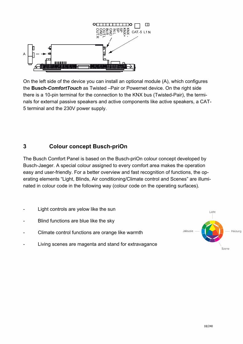
On the left side of the device you can install an optional module (A), which configures the Busch-ComfortTouch as Twisted –Pair or Powernet device. On the right side there is a 10-pin terminal for the connection to the KNX bus (Twisted-Pair), the termi-nals for external passive speakers and active components like active speakers, a CAT-5 terminal and the 230V power supply.
3 Colour concept Busch-priOn
The Busch Comfort Panel is based on the Busch-priOn colour concept developed by Busch-Jaeger. A special colour assigned to every comfort area makes the operation easy and user-friendly. For a better overview and fast recognition of functions, the op-erating elements “Light, Blinds, Air conditioning/Climate control and Scenes” are illumi-nated in colour code in the following way (colour code on the operating surfaces).
- Light controls are yelow like the sun
- Blind functions are blue like the sky
- Climate control functions are orange like warmth
- Living scenes are magenta and stand for extravagance

19/240
A signposting that is international, independent from speech. Additional you can attach easy function-symbols, so that labelling the touch surfaces is almost unnecessary.
4 Range of functions of the Busch-ComfortTouch
4.1 Operating functions
All conventional functions in building automation can be controlled and have their status displayed, i.e. the basic functions of actuating, dimming, blind value , scenes and measured data can be operated and displayed.
4.2 Room temperature control
The Bush Comfort Panel includes a local temperature controller inside the unit.
Furthermore, the temperature of various rooms can be controlled centrally by the unit, i.e. only one actual temperature needs to be available from the various rooms (e.g. ex-ternal temperature sensor) and the Busch Comfort Panel can then control the tempera-ture.
The control of external room thermostats is also possible.
20/240
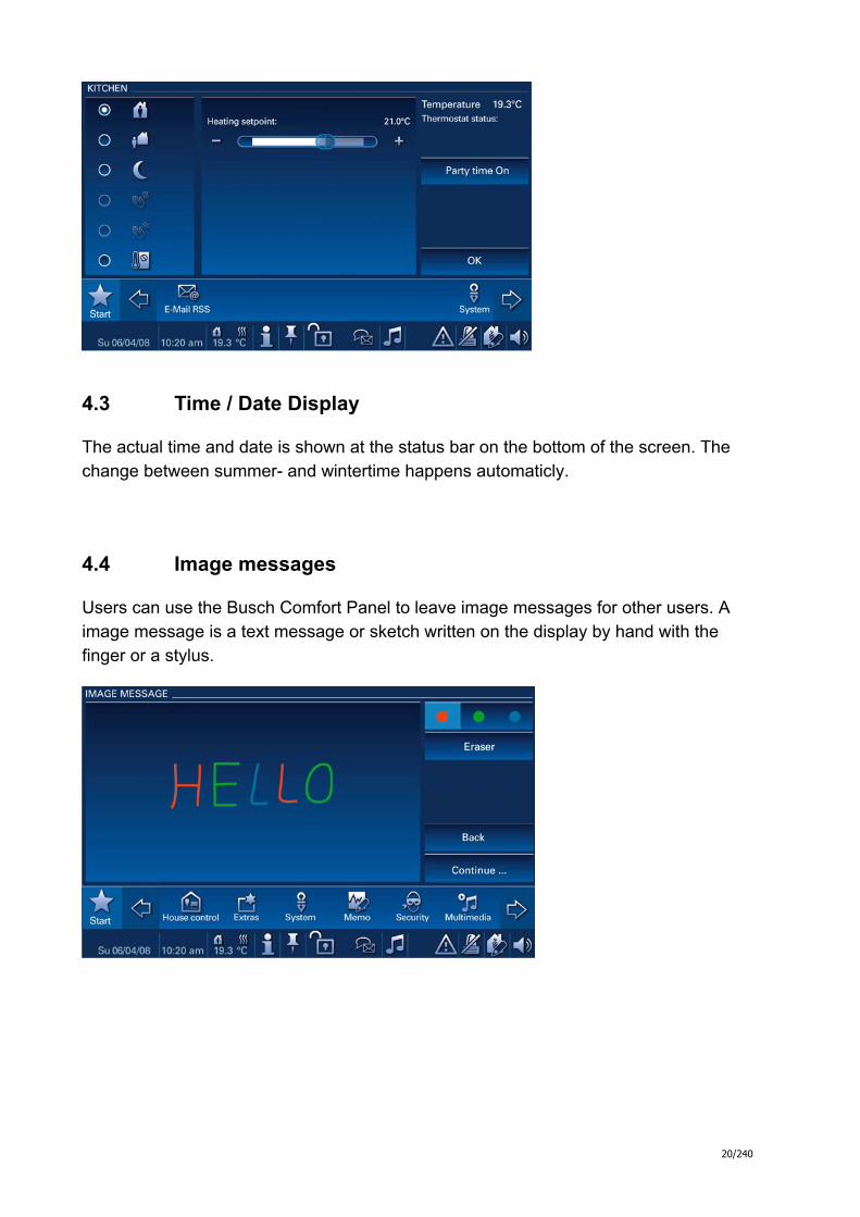
4.3 Time / Date Display
The actual time and date is shown at the status bar on the bottom of the screen. The change between summer- and wintertime happens automaticly.
4.4 Image messages
Users can use the Busch Comfort Panel to leave image messages for other users. A image message is a text message or sketch written on the display by hand with the finger or a stylus.
21/240
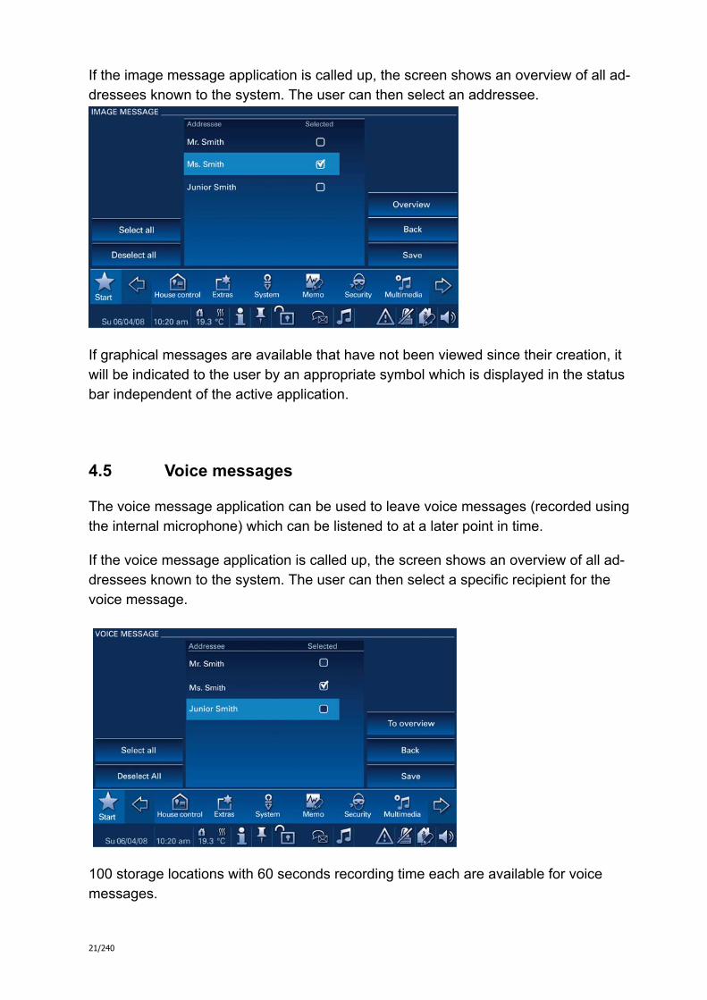
If the image message application is called up, the screen shows an overview of all ad-dressees known to the system. The user can then select an addressee.
If graphical messages are available that have not been viewed since their creation, it will be indicated to the user by an appropriate symbol which is displayed in the status bar independent of the active application.
4.5 Voice messages
The voice message application can be used to leave voice messages (recorded using the internal microphone) which can be listened to at a later point in time.
If the voice message application is called up, the screen shows an overview of all ad-dressees known to the system. The user can then select a specific recipient for the voice message.
100 storage locations with 60 seconds recording time each are available for voice messages.
22/240
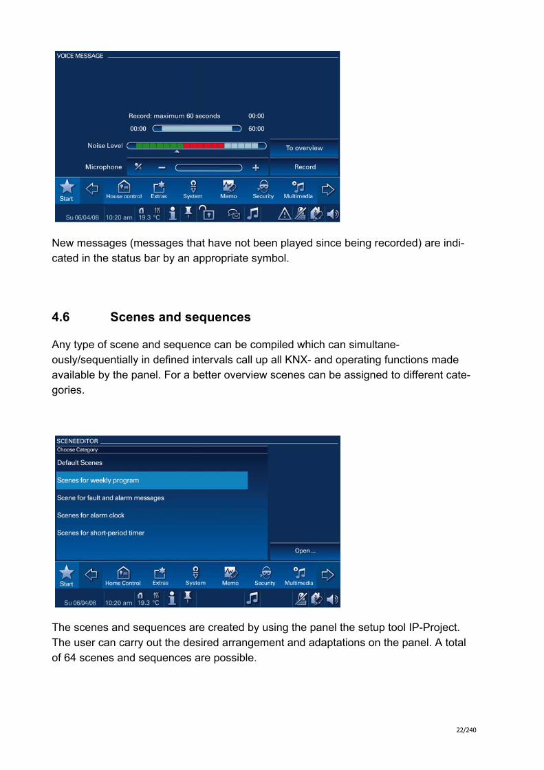
New messages (messages that have not been played since being recorded) are indi-cated in the status bar by an appropriate symbol.
4.6 Scenes and sequences
Any type of scene and sequence can be compiled which can simultane-ously/sequentially in defined intervals call up all KNX- and operating functions made available by the panel. For a better overview scenes can be assigned to different cate-gories.
The scenes and sequences are created by using the panel the setup tool IP-Project. The user can carry out the desired arrangement and adaptations on the panel. A total of 64 scenes and sequences are possible.
23/240
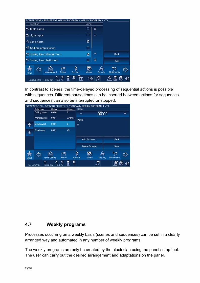
In contrast to scenes, the time-delayed processing of sequential actions is possible with sequences. Different pause times can be inserted between actions for sequences and sequences can also be interrupted or stopped.
4.7 Weekly programs
Processes occurring on a weekly basis (scenes and sequences) can be set in a clearly arranged way and automated in any number of weekly programs.
The weekly programs are only be created by the electrician using the panel setup tool. The user can carry out the desired arrangement and adaptations on the panel.
24/240
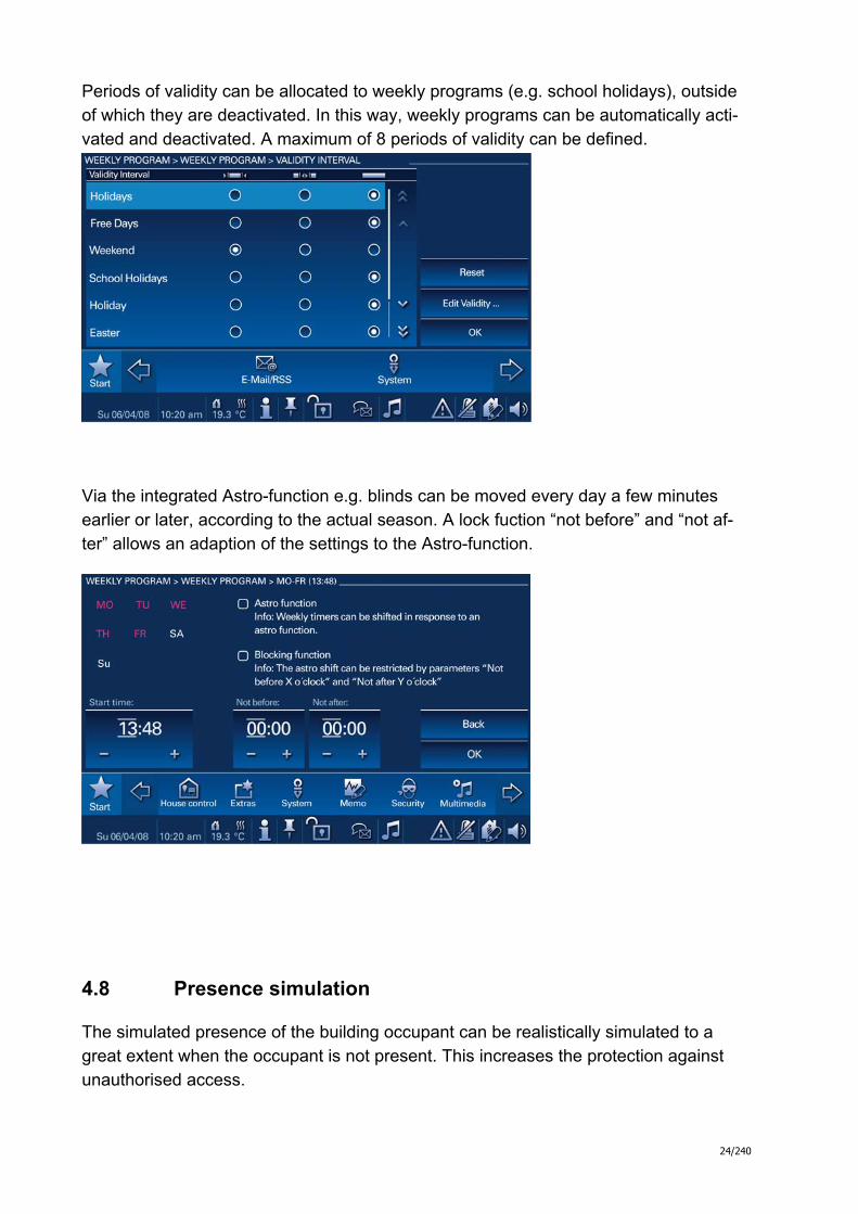
Periods of validity can be allocated to weekly programs (e.g. school holidays), outside of which they are deactivated. In this way, weekly programs can be automatically acti-vated and deactivated. A maximum of 8 periods of validity can be defined.
Via the integrated Astro-function e.g. blinds can be moved every day a few minutes earlier or later, according to the actual season. A lock fuction “not before” and “not af-ter” allows an adaption of the settings to the Astro-function.
4.8 Presence simulation
The simulated presence of the building occupant can be realistically simulated to a great extent when the occupant is not present. This increases the protection against unauthorised access.

25/240
The Busch Comfort Panel records (weekday-specific) up to 20 objects of all actions precisely to the minute and then plays these back true to the original.
4.9 Access control
Different users or user groups can be defined, with a password allocated to each one. This protects specific operating buttons, applications or pages (e.g. video monitoring or operating pages) from unauthorised accessed. The Busch Comfort Panel can manage up to 8 different user groups.
4.10 Malfunction and alarm display
The Busch Comfort Panel offers protection and information during malfunction or inter-ference.
Signal contacts, sensors and their proper function can be monitored. The message is-sued in the event of a malfunction or notification can be set individually. The following can be selected: info, alert, graphical representation on the screen, e-mail and scene for information or prevention.

26/240
The malfunction and alarm messages contain a system of acknowledgement by two steps. The 100 latest messages are stored in the Busch-ComfortTouch and can be displayed.
4.11 Message centre
The Busch Comfort Panel can monitor message circuits/contacts and display their status. This enables the panel to monitor the security of the building and, if necessary, to transmit messages about unauthorized access.
A maximum of 8 message circuits are available for the monitoring whereby the number of the signal contacts is limited on max. 30..
4.12 A/V surveillance
A/V surveillance provides fast, visual information about events occurring within the de-tection range of connected cameras. The surveillance cameras can be triggered and the transmission signal displayed.

27/240
A prerequisite is that the surveillance cameras are IP-capable. The Busch Comfort Panel supports cameras from the manufacturers Mobotix and Axis.
If the camera has got an archive, the Busch-ComfortTouch can display it.
4.13 Media-Player
The Busch-ComfortTouch is able to play directly AAC- and MP3 audio files as well as MPEG2 encoded video files via the integrated media-player. For the audio output the integrated speaker or connected (Line out) audio devices can be used.
As source for media files you can use an USB storage device or a SD card. Optional audio and video files can be stored on a network server if it has access to a shared folder/directory.
4.14 Electronic picture frame
Pictures can be presented on the panel display via the integrated screen saver in the Busch Comfort Panel which can be run with different fade-over effects in a type of “slide show”. A USB stick, an SD card or any type of network address can serve as source for the image files.

28/240
4.15 E-mails
E-mails can be displayed without the need for a separate computer. E-mails can be easily answered via the image or voice message.
E-mails are only available via a preset account and POP3. Deleting E-mails directly from the Busch-ComfortTouch is not possible. Preferred E-mail addresses can be stored in a list to allow a fast access.
4.16 Feed reader
The feed reader enables users to read up to 10 "news feeds" in a compact form directly on the Busch Comfort Panel, e.g. the current news, weather, traffic information. The "feed reader" can be displayed on the start page as a compact application and is thus immediately visible.
Optional you can open the feed reader with the navigationbar.

29/240
4.17 Short-period timer (egg timer)
Short-period timers are available on the Busch Comfort Panel. In addition, there is also the option of letting automated scenes run at the start or end. A maximum of 5 short- period timers are available to the user.
Therefore it is possible e.g. to shut all windows in the building at an specific point in time or switch on the garden lights over a specific period.
4.18 Alarm clock
Specific weekday times can be set for activating a specific scene for waking up (e.g. starting the Media-Player with one’s favourite music).
It is also possible to set a scene to precede the alarm, for example to prepare the home environment for its occupants prior to rising (The heating will be turned on one hour before wake up time).
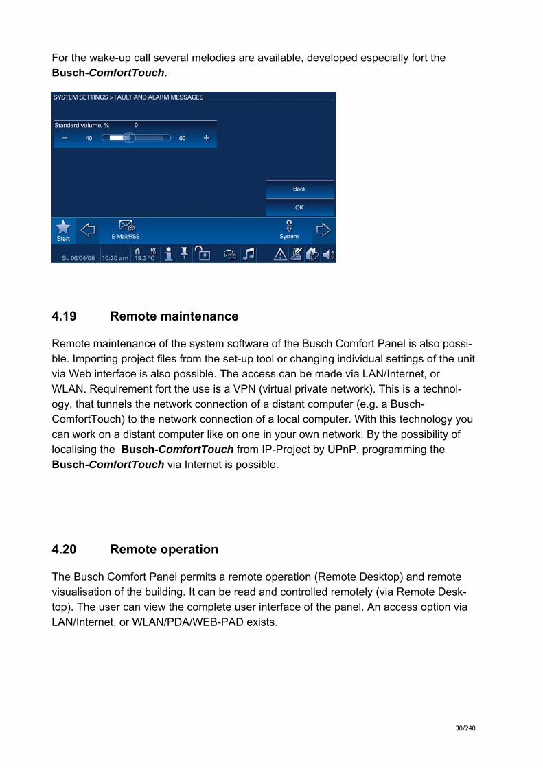
Musical alarm calls especially developed for the Busch-Comfort Panel are available.
30/240
For the wake-up call several melodies are available, developed especially fort the Busch-ComfortTouch.
4.19 Remote maintenance
Remote maintenance of the system software of the Busch Comfort Panel is also possi-ble. Importing project files from the set-up tool or changing individual settings of the unit via Web interface is also possible. The access can be made via LAN/Internet, or WLAN. Requirement fort the use is a VPN (virtual private network). This is a technol-ogy, that tunnels the network connection of a distant computer (e.g. a Busch-ComfortTouch) to the network connection of a local computer. With this technology you can work on a distant computer like on one in your own network. By the possibility of localising the Busch-ComfortTouch from IP-Project by UPnP, programming the Busch-ComfortTouch via Internet is possible.
4.20 Remote operation
The Busch Comfort Panel permits a remote operation (Remote Desktop) and remote visualisation of the building. It can be read and controlled remotely (via Remote Desk-top). The user can view the complete user interface of the panel. An access option via LAN/Internet, or WLAN/PDA/WEB-PAD exists.
31/240
4.21 IR remote control
The Busch Comfort Panel can be controlled via an RC5 or B&O capable IR remote control. To do this, the panel’s functions are programmed to an IR remote control. The available IR functions are defined in the Busch Comfort Panel by the electrician. Pro-gramming of a new IR remote control is also additional possible on the unit itself.
4.22 Web interface
Via the web interface, users can also configure the Busch Comfort Panel (via a browser interface) in addition to the configuration settings on the panel itself. The ac-cess from the Web interface can be protected by passwords.
The possibilities of configuration for the user do not cover the whole spectrum of the possibilities of the Busch-ComfortTouch.
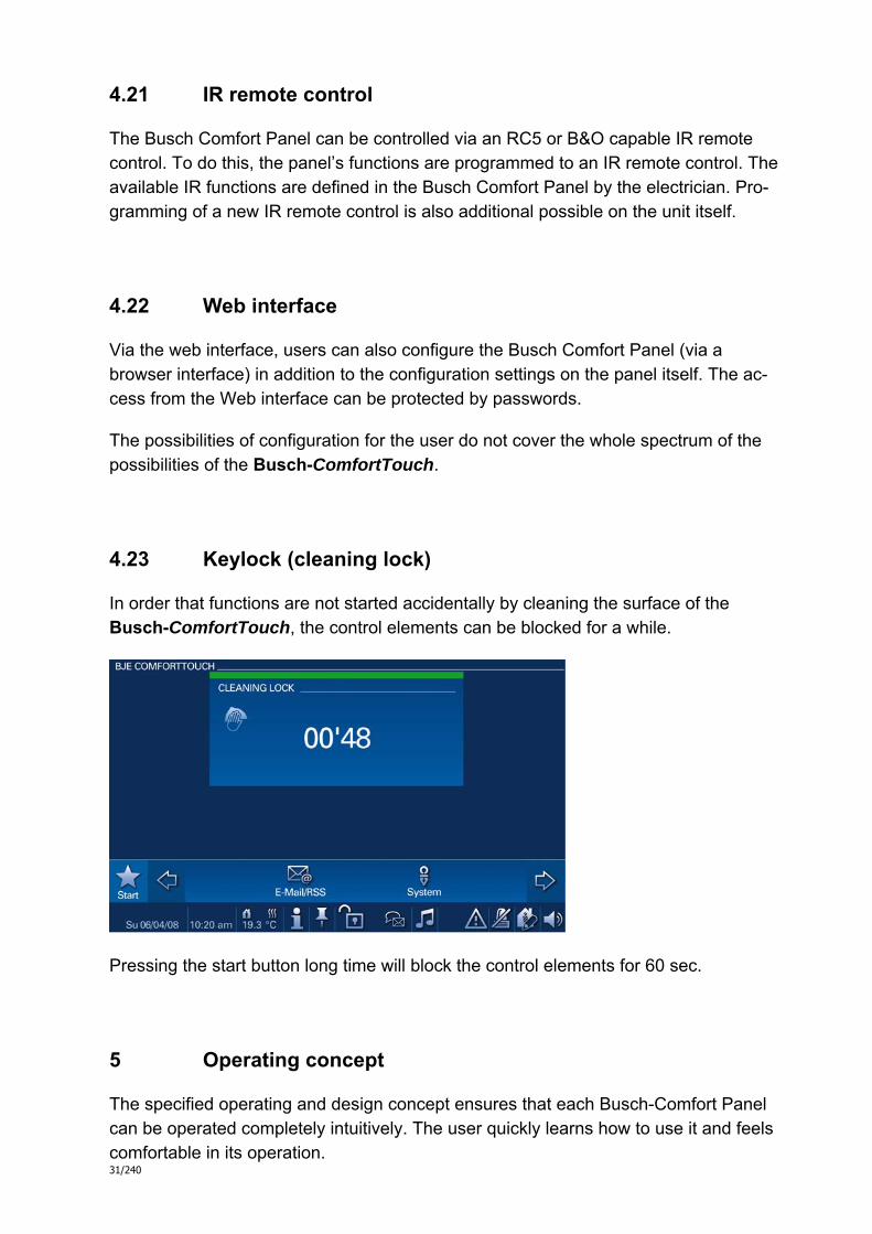
4.23 Keylock (cleaning lock)
In order that functions are not started accidentally by cleaning the surface of the Busch-ComfortTouch, the control elements can be blocked for a while.
Pressing the start button long time will block the control elements for 60 sec.
5 Operating concept
The specified operating and design concept ensures that each Busch-Comfort Panel can be operated completely intuitively. The user quickly learns how to use it and feels comfortable in its operation.

32/240
The option of being able to design operating buttons in different sizes makes it easy to realise operating concepts that allow use by people of all ages. Icons can be selected from one of the supplied comprehensive libraries.
5.1 Status bar
The status line (at the very bottom on the screen) displays the status of the system plus additional information (e.g. date/time). Secondary information can be called up there, which is then displayed in flyout menus.
In turn, applications can then be called up from these menus (e.g. alarm clock set-tings).
The status bar is permanently displayed (exception: screen saver, you must specify whether the status bar is to be displayed or not displayed while the screen saver is on).
5.2 Navigation bar
The uniform operating concept of the navigation bar facilitates a fast and guided navi-gation to the operating pages and applications.
The navigation bar is located in a fixed position on the screen (above the Status bar) and is always accessible on the display for the user. A jump function to the start page is permanently available in the navigation bar on the left edge.
Using the buttons on the navigation bar, the user can navigate to operating pages or call up applications directly by touch. The navigation bar can be freely allocated with buttons whereby the number of buttons that fit on a section depends on the length of text for the designation. This allows the number of buttons on a visible section to be varied. The view of the area can be exchanged page-wise via the navigation areas (ar-row left/right). A maximum of 4 views are possible.
Jump functions to the operating or application pages can be positioned singly and as functional groups (so-called containers). Single jump functions on the navigation bar are triggered directly by touch. Function groups are shown summarised in a touch-activated opening box where the desired actions can also be triggered by touch. Up to six jump functions can be positioned on a box. The height of a opening box on the screen is variable and is sized on the number of entries.

33/240
5.3 Busch-ComfortTouch page types
There are basically three different page types for display on the Busch Comfort Panel:
Start page (welcome page)
This is used for entry into the system on the first level with the user’s favourite functions or for displaying important information.
Operating pages
Navigation to rooms and building sectors with their respective functions is possible by accessing the jump function.
Application pages
Are used for controlling or for settings of the applications and functions by direct selec-tion.
The controlling and setting of applications and functions can be chosen directly.
The controlling or settings of applications and functions happen by direct selection.
5.3.1 Start page functions
Operating functions and applications can be called up directly via the start page.
The various operating elements can be arranged in a grid with a maximum of 4x4 ele-ments (depending on the selected button sizes among other things). This grid applies to both the start page as well as all operating pages.

34/240
5.3.2 Start page with floor plan
With this start page version, direct navigation to the operating pages of the individual rooms is possible via a floor plan view.
Up to 6 floor plan views (datatype: JPG, PNG or GIF; max. resolution: 598x318 pixel) are possible. Up to two displays for the collective status of consumers per room can be shown on every floor plan view.
Observe, however, that a consumer cannot be switched directly from the floor plan view. To do this you must first branch into the room.
5.3.3 Operating page functions
The user can activate the home control functions using the buttons via the operating pages.

35/240
Here too, various operating elements can be arranged in a grid with a maximum of 4x4 elements to a page.
If more than 16 elements are needed on one operating page, you can add up to two additional, subordinated operating pages can be added.
The maximum number of operating elements that can be displayed is reduced to 3x4 due to the space that the swap elements occupy on the screen. Up to a max of 36 op-erating functions can be stored when all three possible pages for a room are totaled.
For better orientation you can, instead of an subordinated operation page, insert a thumbnail picture af the room (datatype: JPG, PNG or GIF, max. resolution 382x312 pixel).
36/240
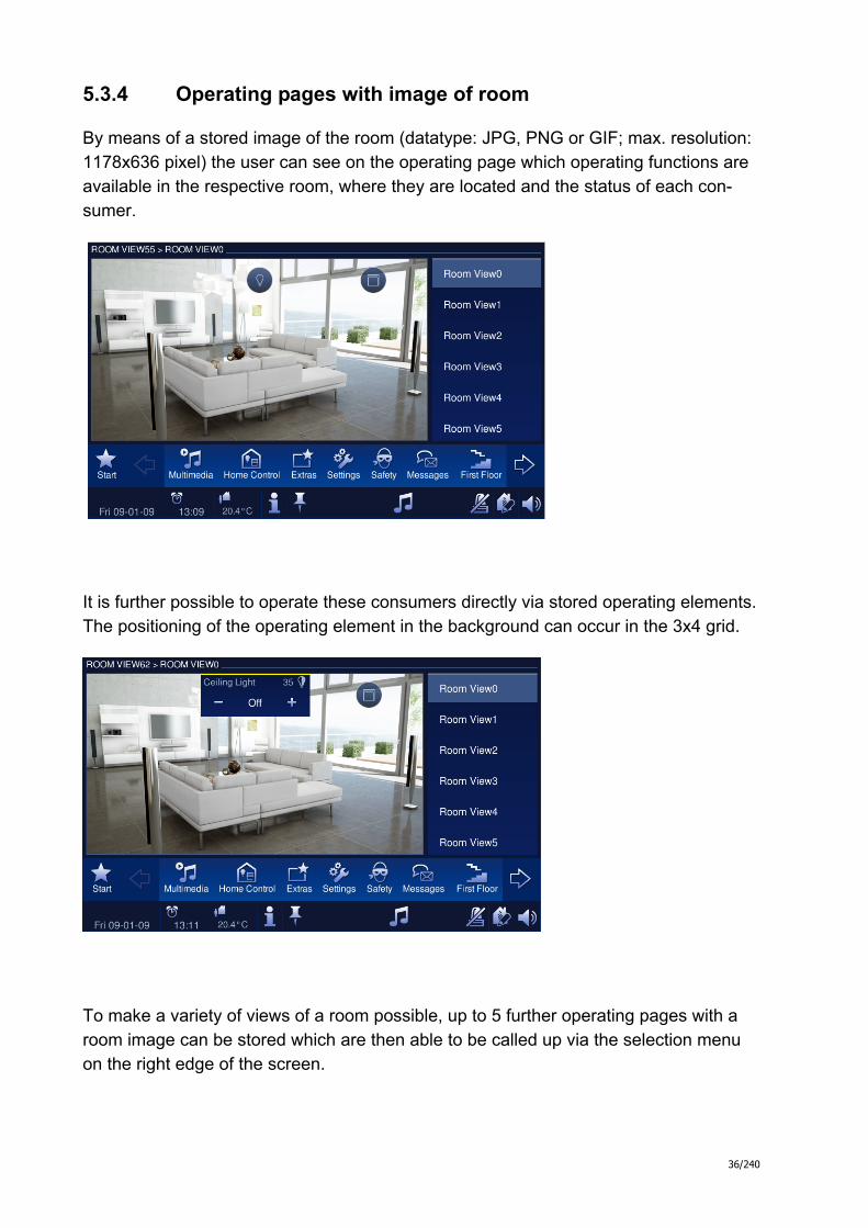
5.3.4 Operating pages with image of room
By means of a stored image of the room (datatype: JPG, PNG or GIF; max. resolution: 1178x636 pixel) the user can see on the operating page which operating functions are available in the respective room, where they are located and the status of each con-sumer.
It is further possible to operate these consumers directly via stored operating elements. The positioning of the operating element in the background can occur in the 3x4 grid.
To make a variety of views of a room possible, up to 5 further operating pages with a room image can be stored which are then able to be called up via the selection menu on the right edge of the screen.

37/240
5.3.5 Application page
Application pages offer the display and operation of application-specific functions of individual applications in full screen mode. In this way, settings for a room thermostat can be made or an Media-Player can be operated
6 Busch Control Panel software
6.1 Installing the Comfort Panel IP Project software
6.1.1 Hardware requirements
For the operation of the Busch-ComfortTouch the following hard- and softwere envi-ronment is recommended:

38/240
Windows XP Processor: 1,6 GHz Main memory: 1 GB RAM Operating system: Windows XP with Service Pack 2 or higher
Windows Vista Processor: 2,0 GHz or Dual Core with 1,6 GHz Main memory: 2 GB RAM Operating system: Windows Vista Business Edition
with: - Support for graphic processor DirectX 9 with WDDM-driver and min. 128 MB graphic storage, - Pixel Shader 2.0 and 32 Bit per Pixel - 40 GB hard drive capacity with 15 GB free space - DVD-ROM-drive - Possibility for audio output - Access to the internet
6.1.2 Installation sequence of the IP Project software
The following describes the individual installation steps that are required for the instal-lation of the commissioning IP Project software (IPP) for the Busch Comfort Panel.
Please observe the related hardware and software requirements listed above for a proper installation and function of the software. In particular, you need to have full ad-ministrator rights to the operating system.
An installation wizard will assist you with the installation of the IP Project software. This is started by double-clicking on the "Setup_IPP10_BJE.exe" or “Setup_IPP10_ABB.exe” file on the installation-CD and can run in both languages German and English.
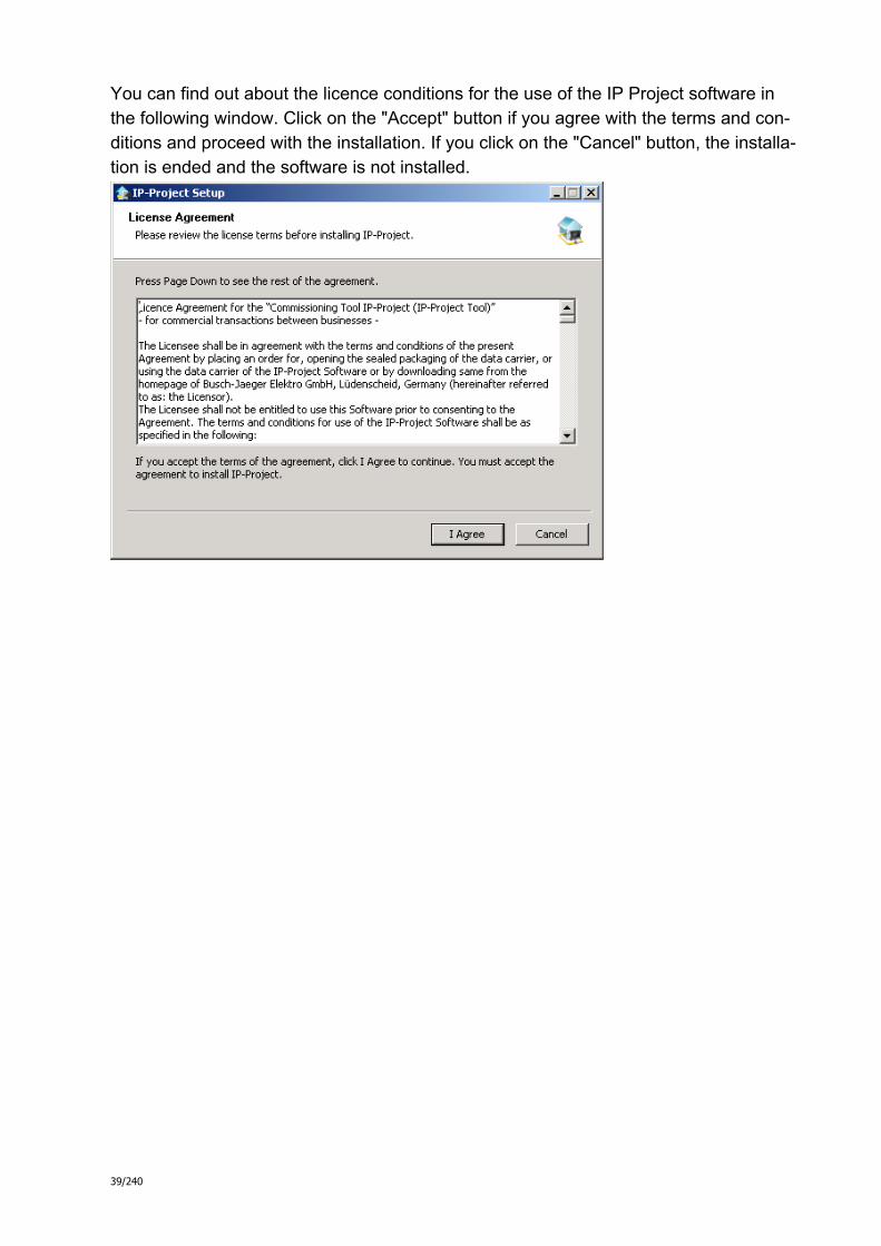
39/240
You can find out about the licence conditions for the use of the IP Project software in the following window. Click on the "Accept" button if you agree with the terms and con-ditions and proceed with the installation. If you click on the "Cancel" button, the installa-tion is ended and the software is not installed.

40/240
You have the option of selecting individual software components in the following dialog window. The IP Project files are mandatory for the functioning of the software and are thus not able to be deselected.
After clicking on the "Next" button you can specify which target directory to use for the program installation. By default, this is: "C:\Programs\IPP".

41/240
After you have confirmed this dialog with "Install", the installation wizard carries out the installation to the target directory.
A progress bar is visible for visually monitoring the progress of the installation. When the installation is completed, the installation procedure can be ended by clicking on the active "End" button.
Note:
Please observe the possible software updates (service releases) in the Internet under www.busch-jaeger.de, in order to be up-to-date with the most current software.
6.2 Installation of the Busch Comfort Panel ETS3 macro
For the correct im- and export of group addresses it is necessary to install a special Busch-ComfortTouch macro. You can start this macro within the ETS3 by an addi-tional button.
6.2.1 Prerequisite
A licensed version of the ETS3 Professional software must be installed on the target computer for the installation.

42/240
6.2.2 Installation sequence
An installation wizard will assist you with the installation of the ETS3 macro for the Busch Comfort Panel. This is started by double-clicking on the "Macros.exe" file and can run in either German or English.
6.2.3 Integration of the Busch Comfort Panel in the ETS3
Start the ETS3 and import the product data of the Busch Comfort Panel ".vd4-file" via the import function of the ETS3 into the project database.
7 Comfort Panel IP Project software
7.1 Recommended sequence of a project planning
The following working sequence (standard workflow) is recommended for working most effectively with the IP Project software:
1. Start the software and create a new project (project info, name panel, ...).
2. If the ETS3 project already exists, import the group addresses already created
there into IP Project udn weisen Sie den richtigen Datenpunkttyp (DPT) allen im Busch-ComfortTouch verwendeten Gruppenadressen zu (z.B. Funktion 1.001 Switch)
3. Configure the panel (basic settings, feed reader, web browser, …).

43/240
4. Specify the navigation structure (insertion of operating and application pages).
5. Configure the operating pages (insert and configure control elements).
6. Configure the application pages (insert and configure applications).
7. Now configure the start page (insert and configure control elements). 8. If additional panels are to be installed, start again at point 2 or duplicate the
entries of an already existing panel.
9. If all entries have been carried out, perform a consistency check (test and pos sible debugging).
10. Transfer the project to the panel and start it up.
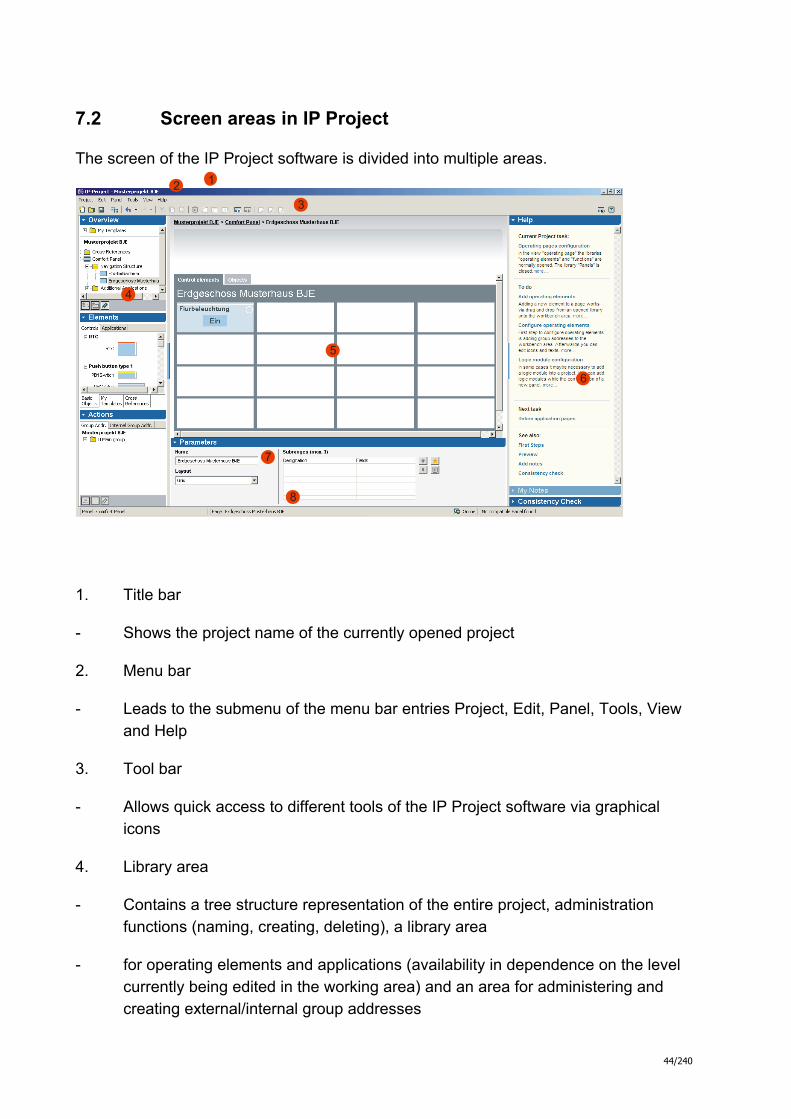
44/240
7.2 Screen areas in IP Project
The screen of the IP Project software is divided into multiple areas.
2 1
3
5
4
7
8
6
1. Title bar
- Shows the project name of the currently opened project
2. Menu bar
- Leads to the submenu of the menu bar entries Project, Edit, Panel, Tools, View and Help
3. Tool bar
- Allows quick access to different tools of the IP Project software via graphical icons
4. Library area
- Contains a tree structure representation of the entire project, administration functions (naming, creating, deleting), a library area
- for operating elements and applications (availability in dependence on the level currently being edited in the working area) and an area for administering and creating external/internal group addresses

45/240
5. Working area
- Facilitates working on panel, navigation and page levels.
- Displays graphically (similar to the Busch Control Panel) (WYSIWYG)
- Facilitates the allocation of free spaces via drag & drop
- Makes a filing sector available in the upper area for "parking" temporary, un used operating elements and pages.
6. Help area
- Makes a context-related excerpt from the online help available
- Contains a to-do list with suggestions and its own to-do notes
- Displays the result of a consistency check of the current view, of the complete panel and of the complete project
7. Parameter area
- Offers context-sensitive (depending on selected element in the working area) input and setting options.
- Parameter settings are shown locally according to layout (left) and separately related to function
- Contains the access to expanded settings and editors of the applications
8. Status bar
- Shows panel and page in which project planning is currently being performed
- Signalises a general LAN connection status (online/offline)
- Contains a compact display of the results of the infrastructure detection ("x compatible panels found"/"No compatible panel found")
The areas 4 (library area) and 6 (help area) can be hidden or unhidden by clicking on the narrow blue fields.
The display of the IP Project software is optimised for a screen resolution with 1280x1024 pixels. Screen resolution with 1024x768 is also possible.
46/240
7.3 Operating the IP Project software
7.3.1 Copying a project
To provide multiple panels with the same functionality (creating a duplicate of an al-ready configured panel), right-click in the left overview window on the original panel and select "Copy". This panel is then inserted to the project again and is now available as copy for additional editing.
7.3.2 Moving/copying pages and operating elements
Containers, pages and operating elements can be moved to the upper grey copy area using the mouse and reinserted at a different location in the project. If the Ctrl button is held pressed before moving with the mouse, IP Project creates a copy of this element and places this in the copy area.
Each page and every operating element can be stored as a permanent template. Right-clicking on the corresponding element and selecting the "Save as template" menu cop-ies the corresponding object in the overview “My templates” to the corresponding sub-directory template folder where it is then permanently available.
7.3.3 Cross references
Control elements and pages can be stored as cross referrence.
Therefore you can click with the right mouse button on the element and choose “Con-vert to cross reference”. If you use this elements at several places in one project, you can edit these central from the overview screen in the directory “cross reference”. Changes will then be assumed to all related elements.
7.3.4 Consistency check
There is the option to perform a consistency check after completion of all entries. Diese Funktion kann im Hilfebereich aufgerufen werden. Wahlweise kann nur die aktuelle Ansciht, das momentan bearbeitete Panel oder das gesamte Projekt überprüft werden.
All input is tested for plausibility and the result is shown in the help window. By double-clicking on the entries shown there, you can get to the associated screen page of the programming directly.

47/240
Detected inconsistencies will be devided into „serious inconsistecies” that have to be removed before transferring the project to a Busch-ComfortTouch and “less serious inconsistencies”, that should be removed, but don’t have influence to the functionality.
7.4 Downloading project into panel
If the project with the IP Project software is finished, it can be loaded into the Busch Comfort Panel. You will find the entry "Load project" under the "Project" menu item in the IP Project software. If you select this entry, the following appears on the screen:
If you have configured multiple panels at the same time in a project file of the IP soft-ware, you can select which of these panels you would like to install first.
You then provide the installation path. If the panel is connected with the PC (USB, LAN, WLAN,…), the data can be transferred directly to the panel after successful iden-tification by the software. Alternatively, an installation via memory card (SD-card or USB stick) is possible. To do this, select the "Save to file system" option and specify the corresponding storage location there.
You can then subsequently read in the exported project data again after clicking on the "System" button and selecting the "Import" option.

48/240
8 Getting started - a first project
The following sample project will show you how to work with the IP Project software.
8.1 Project start
First, start the IP Project program on the hard drive of your computer and use the "New project" button to call up the start mask for a new project.
8.2 Importing of group addresses
If group addresses were created in an ETS3 project which are also to be used in the Busch Comfort Panel, you can read these in again here after an export from the ETS3. To do this, you need to specify the corresponding file path in the upper area of the in-put window.
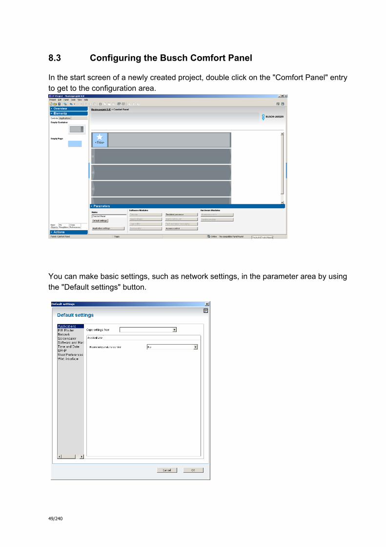
49/240
8.3 Configuring the Busch Comfort Panel
In the start screen of a newly created project, double click on the "Comfort Panel" entry to get to the configuration area.
You can make basic settings, such as network settings, in the parameter area by using the "Default settings" button.

50/240
After clicking on the "Application settings" button in the "Parameter" window, you can make settings in a separate window for the use of different applications. Please con-sider, that some settings are only available, when the according application is projected or placed on the screen.
Note: You can find more detailed information about the different setting options in the online help of the IP Project program.
8.4 Navigation structure
You can insert elements in the navigation bar from the "Elements" library window on the left. To do this, drag (using the left mouse button) the corresponding element to the grey bar in the working area and let it drop (drag & drop). Using this method, so-called containers (these can contain additional screen pages), screen pages or applications (from the "Applications" area in the "Elements" window) can be placed on the naviga-tion bar.
In order to fill an empty container with additional sub-pages, you must click on the small arrow on the left side of the corresponding grey bar in the navigation bar. You can then insert up to six additional pages.
If you want to change the order of the entries in the navigation bar, simply use the drag & drop method to do this. In this way, you can create the navigation structure in the navigation bar that the end user will then see.

51/240
After clicking, the elements can be labelled and you can also assign them icons for making them easier to identify. Eine entsprechende bibliothek können Si emit dem but-ton “Durchsuchen” im Parameterfenster öffnen.
Note: The upper grey bar in the working area is permanently assigned with the jump button to the Busch Comfort Panel start page and cannot accept any further elements.
The following screenshot shows a possible design of a navigation structure for a small sample project.
8.5 Configuring the operating pages (functions)
The following shows how a function (here: "Switch ceiling lamp in living room") can be configured.
Call the operating page for the living room via the "Ground floor" container by double-clicking. Alternatively, you can also call up this page by double-clicking in the left win-

52/240
dow "Overview" from the navigation structure.
If you require more than the maximum number of displayable elements (4x4) on a page in the basic form, you can add up to two additional sub-pages. These sub-pages are visualised right on the display of the Busch-ComfortTouch.
The sub-pages can be created and labelled in the parameter field by clicking on the star button.
However, you should consider reducing the maximum number of operating elements that can be displayed per screen page to 3x4 due to the space that the swap elements occupy on the screen.

53/240
As specified at the beginning, the light in the living room shall be able to be switched on and off using the Busch Comfort Panel. To do this, drag the "Light (toggle)" element using the left mouse button from the left window "Elements" to the desired field on the screen page of the living room.
Note: You can find complete descriptions about the functions, possibilities and parame-ter settings of the different control elements in the IP Project online help.
You should now assign an appropriate name to the operating element so that the end user can quickly find his or her way around the Busch Comfort Panel (suggestion: Ceil-ing lamp). In the operating field for the user, you can also create a note about the exe-cuted function from the Busch Comfort Panel for a renewed operation. If, for example, the light is switched on, then the operating field might show the label "Off" as informa-tion about the subsequent switching activity. Enter the desired texts in the parameter field under "Value 1" or "Value 2". If you prefer to use icons, this is also possible.
Now proceed with the parameterisation of the operating element.
Click on "Advanced settings" to get to the parameter window of the operating element currently being edited. You can make different entries here which will then lead to the desired functionality.
The integrated IP Project software online help also provides comprehensive support for the individual settings options.
Confirm your entries with "OK".
If you have already made changes to an identical operating element, you can simply copy these directly. To do this, select the reference operating element in the "Copy set-tings from" field.

54/240
If you have an element active (clicked on), you can make the "Object" entry visible in the upper line of the page of the associated KNX communication object. If you already had imported group addresses from a KNX project, these can now be assigned (ap-propriate to the task) per drag & drop to the communication objects from the group ad-dress window.
If you would like to use new group addresses, you can create main and middle groups using the small left button in the group address field. The sub-groups can then be cre-ated using the middle button (important: you have first clicked on the corresponding middle group).
In addition, you can create and use internal group addresses. These are only used for the communication within the Busch Comfort Panel. For a subsequent export of all group addresses, these are not included in the export and are thus also not visible in the ETS3 project.

55/240
You can check the result in the panel preview after you have performed all settings. The panel preview simulates the Busch Comfort Panel true to the original.
The panel preview window opens after you have clicked on the preview button in the upper right in the working area. Using the mouse, you can now operate the preview as you would using your finger on the Busch Comfort Panel.
8.6 Start page with floor plan or room image
One characteristic of the start page with floor plan or image is that an object cannot be directly operated through this. The welcome screen is in this case only needed for link-ing to subordinated pages. Starting e.g. a switching function direct from the welcome screen is only possible in the “raster” view.
Hint: A floor plan or an image on the start page may have a maximum resolution of 589x318 pixels.

56/240
As example, the following start page shows a branching has been selected to the dif-ferent floors of a home.
If a floor plan or a room picture is loaded, in the library at the left side of the screen the control element “room” is available in the field “elements”. This element can be drawn onto the screen and customised to the picture size. Now you have created a sensitive area for touch control. After clicking on this area you can define the target, where to jump (e.g. Pagename). You can define the target in the lower parameter window via the button “Browse path”.

57/240
Note: You must have previously created all operating pages that are to be used as jump target first. You can otherwise not enter jump target specifications here (see also chapter: Recommended sequence of a project planning).
By double clicking a sensitive surface or by touching the button “extended settings” while choosing a sensitive surface you are linked to the related configuration page.
Angled rooms can be recorded very well by covering these with multiple sensitive ar-eas with the same jump target (e.g. same operating page).

58/240
8.6.1 Operating pages with floor plan or room view
If you select the "Room image" view (large view) under "Layout" in the parameters on an operating page, you initially receive only a grey operating page. In this state, i.e. without a room image, you can not yet place any operating elements on the screen.
If you would now like to load a room image (floor plan or room view), add these under "Sketches" by clicking on the star button.
Please observe here that the maximum resolution of the file may not exceed 1178x636 pixels.
Once the room image has been loaded, a 3x4 field grid opens over it which you can now use to place operating elements.
Up to six different room views with 3x4 field can be created on every operating page.

59/240
The end user sees the stored operating functions on the Busch Comfort Panel depend-ing on the parameter settings as blue circle (no status), as blue circle with an icon (with status) or with specified text.
In the following preview image, a representation with icon and status was selected as example.
If the user clicks on an icon on the Busch Comfort Panel, the associated operating element becomes completely visible and operable.

60/240
8.7 Operating pages with small image of room
Another way of creating operating pages is by integrating a small room image. To do this, select the page layout "Grid with room view (small view)". Please observe that the upper limit of 382x312 pixels may not be exceeded for the room image.
The room image is fixed in the upper right corner of the operating page. It provides the user with a better orientation and thus increases the clarity.

61/240
8.8 Integration of applications
You can assign applications ( eine deteillierte Beschreibung der verschiedenen An-wendungen finden Sie im Kapitel 9.9 und in der Onlinehilfe des programms IP-Projct) to the navigation bar and to a container directly. One exception is the feed reader ap-plication. You can alternatively place these directly on the start page.
To increase the clarity, you have the option of grouping applications associated by topic in a common container.
You can set the parameters of these after double-clicking on the respective application. For more detailed information, please see the IP Project online help.
.

62/240
Online help of the program IP-Project
Advice: The following chapters are extracted from the Online help of the configuration software IP-Project.

63/240
Advice
Disclaimer All documents are produced and proved with accurancy. Never the less failings can’t be excluded completely. Therefore Busch-Jaeger Elektro GmbH can’t take over juristi-cal responsibility according to the content. Technical modifications remain always feasable!
9 Logic functions
9.1.1 Using logic functions
Complex switching sequences can be realised in the Com-fort Panel using so-called Logic functions which can be configured in the graphical logic editor of IP Project. Logic functions essentially consist of logic modules that are organised into a logic network. Input and output modu-les are interfaces of the logic network to a KNX or IP-based network (see section Input and output modules).
Notes:
The logic functions are event-controlled. For every arrival of a telegram at an input module, all logic modules affected by this event are re-calculated.
If the recalculation of a logic function is trigge-red by a telegram input, the input modules are allocated with the value of the last telegram to come in.
Time-controlled logic functions automatically carry out a recalculation after expiry of the specified time.
Within a logic network, only the five data ty-pes Boolean, Number, Date, Time, as well as String are used instead of the KNX data types.
The logic engine of the Comfort Panel is a ca-pable and complex tool for a smart and effi-cient realization of logic networks. However, it must be kept in mind that a logic network is triggered on each arriving telegram. That is, the logic network is re-calculated on each new telegram and new output telegrams are sent. When used in an inappropriate way this may lead to an overload of the KNX bus!

64/240
9.1.2 Creating logic functions
The logic editor in IP Project is a graphical editor. Diffe-rent logic modules can be placed on a worksheet and con-nected to each other which produces a logic network. Like the IP Project main window, the logic editor consists of a worksheet in the middle, a library area on the left side and a parameter area in the lower area.
Note: The logic editor can be called up only when this software module has been previously activated (see Activating addi-tional applications).
9.1.2.1 Creating logic functions
Normally, one logic network is arranged per worksheet. Therefore, create a new worksheet when you want to crea-te a new logic function. To do this, use the button in the left library area under Overview . You can also call up existing worksheets for editing in this area.
You can give the worksheet - and thus your logic network - a name in the title of the worksheet.
9.1.2.2 Placing and configuring logic modules
In principle, any number of logic modules can be placed and connected with each other on a worksheet. Each mo-dule represents an arithmetic operation. In the available logic modules section below, you can read which modules are suitable in your case.
You can find all available logic modules in the left library area under Elements. If you want to place such a module, drag it from Elements to the worksheet (see Add element from library). For better comprehensibility, you should place inputs on the left side, outputs on the right side and logic modules in the middle of the worksheet. The directi-on of execution of a logic module in the Comfort Panel then corresponds to the reading direction on the worksheet.
Select a module to rename it. In the parameter area, you can specify (if needed) the number of entries and call up the Advanced settings dialog. In the available logic modu-les section below, you can read which special settings for the individual modules are possible.
Note: Move the mouse pointer over an input or output of a logic

65/240
module to see a tooltip that shows the meaning of the input or output.
9.1.2.3 Linking logic modules with each other
In order for a logic network to function correctly, the logic modules in the worksheet must be linked into to a network. Every logic module contains outputs for this (right of the module), which, using connectors , can be linked to the inputs (left) of other logic modules.
To link two modules to each other, first click on the output of the first module and hold the mouse button pressed. Now drag a connection to the input of the second module.
9.1.2.4 Creating feed-back loops
You can create feed-back modules using a KNX output module and a KNX input module. To do this, provide both modules with identical internal group addresses (see secti-on Input and output modules).
Incoming values are thus transferred from the KNX output module to the KNX input module - however, not until the next calculation cycle! A calculated value can thus flow into the next calculation of the logic again.
9.1.3 Available logic modules
9.1.3.1 Input and output modules
Under I/O modules in the library area, you can find modu-les that make the following connections to actuators and sensors in the network possible:
KNX input modules can receive tele-grams from KNX sensors or actuators. Details
KNX output modules can send tele-grams to KNX actuators. Details
IP input modules can receive TCP- or UDP-based data from sensors or actuators. Details
IP output modules can send TCP- or UDP-based data to actuators. Details

66/240
9.1.3.2 Boolean logic modules
Under Boolean operators in the library area, you can find modules that make the following logical arithmetic opera-tions possible:
AND modules offer the option of the AND linking of 2-8 inputs. Details
OR modules offer the option of the OR linking of 2-8 inputs. Details
XOR modules offer the option of the exc-lusive OR function linking of 2-8 inputs. Details
NOT modules offer the option of inverting logical values. Details
9.1.3.3 Comparator
Under Comparator in the library area, you can find modu-les that compare or check the values at the inputs:
Equal: Checks the values of both inputs for compliance. Details
Not equal: Checks the values of both in-puts for inequality. Details
Greater: Checks whether the one input va-lue is greater than the other input value. Details
Greater or equal: Checks whether the one input value is greater than or equal to the other input value. Details
Less: Checks whether the one input value is less than the other input value. Details
Less or equal: Checks whether the one input value is less than or equal to the other input value. Details
Area tester (internal) specifies whether an incoming comparison value lies between two limit values. Details
Area tester (external) specifies whether an incoming comparison value lies outside two limit values. Details
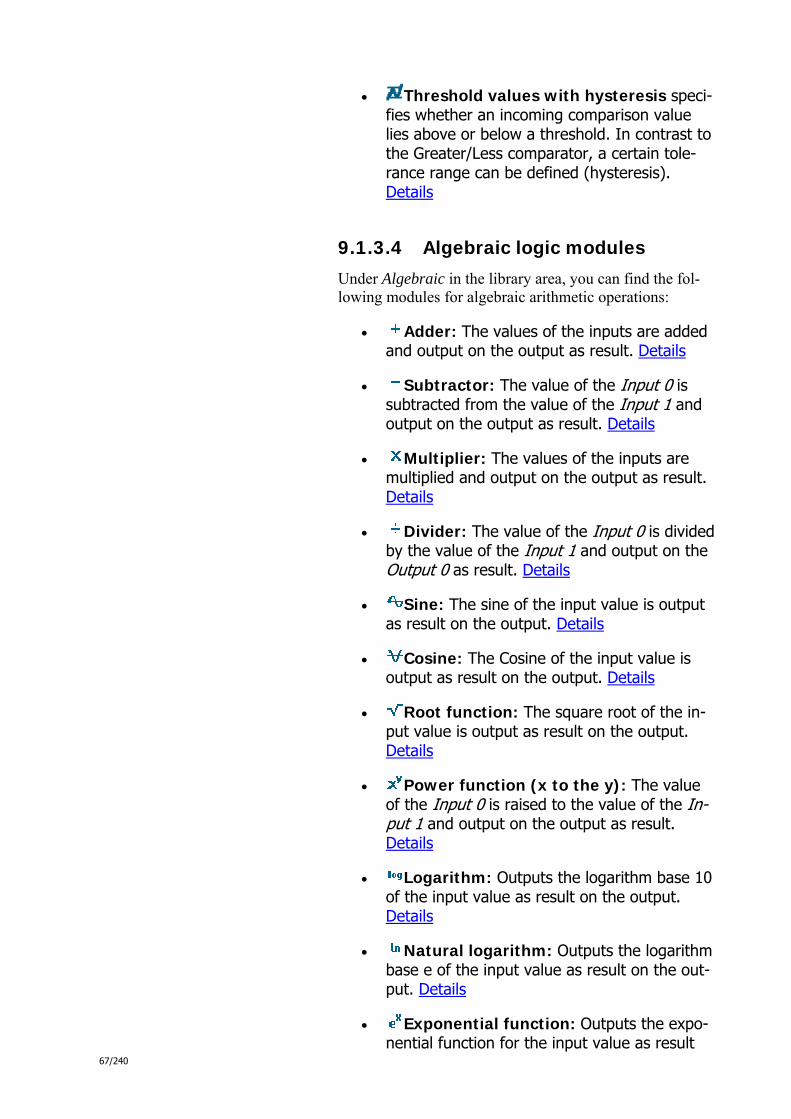
67/240
Threshold values with hysteresis speci-fies whether an incoming comparison value lies above or below a threshold. In contrast to the Greater/Less comparator, a certain tole-rance range can be defined (hysteresis). Details
9.1.3.4 Algebraic logic modules
Under Algebraic in the library area, you can find the fol-lowing modules for algebraic arithmetic operations:
Adder: The values of the inputs are added and output on the output as result. Details
Subtractor: The value of the Input 0 is subtracted from the value of the Input 1 and output on the output as result. Details
Multiplier: The values of the inputs are multiplied and output on the output as result. Details
Divider: The value of the Input 0 is divided by the value of the Input 1 and output on the Output 0 as result. Details
Sine: The sine of the input value is output as result on the output. Details
Cosine: The Cosine of the input value is output as result on the output. Details
Root function: The square root of the in-put value is output as result on the output. Details
Power function (x to the y): The value of the Input 0 is raised to the value of the In-put 1 and output on the output as result. Details
Logarithm: Outputs the logarithm base 10 of the input value as result on the output. Details
Natural logarithm: Outputs the logarithm base e of the input value as result on the out-put. Details
Exponential function: Outputs the expo-nential function for the input value as result

68/240
on the output. Details
9.1.3.5 Additional mathematical logic modules
Under Advanced math in the library area, you can find the following modules for additional mathematical arithmetic operations.
2-point curve function: A linear slope is defined with two points that can be used to calculate the function values f(x). Details
4-point curve function: A curve progres-sion is defined with four points that can be used to calculate the function values f(x). Details
Minimum value: The smallest of all recei-ved values is output on the output. Details
Maximum value: The largest of all recei-ved values is output on the output. Details
Absolute value: Outputs the input value as result without the algebraic sign. Details
Random value: This logic module returns random numbers. Details
Arithmetic average (average): The arithmetic average of all received values is output on the output. Details
Counter: This logic module counts the number of the received values. Details
9.1.3.6 Signal control logic modules
Under Signal control in the library area, you can find the following modules for the signal control:
Delayer: This logic module allows you to realise a delay. Details
On/Off delayer: This logic module allows you to realise two delay times via one binary input value. Details
Staircase lighting: This logic module al-lows you to combine a switching on with a de-
69/240
layed switching off. Details
Lock: This logic module allows you to block the transfer. Details
Filter: This logic module allows you to transfer only certain Boolean values. Details
Text filter: This logic module allows you to transfer only certain string values. Details
Text divider: This logic module allows you to divide the string values into preamble, command, parameter and postamble. Details
Demultiplexer: This logic module allows you to convert serial signals into parallel ones. Details
Multiplexer: This logic module allows you to serialise parallel signals. Details
Number of input: This logic module out-puts the number of the received input. Details
RS-Flip-Flop: This logic module allows you to realise an on/off switch via two binary in-puts. Details
9.1.3.7 Logic modules for signal generation
Under Signal generation in the library area, you can find the following modules for the signal generation:
Constants module: This logic module al-ways outputs the same fixed value (constant). Details
Oscillator: This logic module generates pulse strings or individual pulses and outputs these. Details
Telegram generator: This logic module allows you to combine multiple values into one telegram. Details
9.1.3.8 Logic modules for time and
70/240
date
Under Time and Date in the library area, you can find the following modules for time- and date-dependent arithmetic operations:
Operating hours counter: This logic mo-dule counts the number of operating hours of the Comfot Panel and outputs this. Details
Sunrise and sunset: This logic module al-lows you to output values at the time of the sunrise or sunset. Details
Time generator: This logic module allows you to output the time of day and date. Details
10 Help topics
This section contains information about the fundamentals and tasks of project planning with IP-Project.
10.1 Help pages in this chapter
IP-Project fundamentals:
o Properties of the Comfort Panel
o General operation of IP-Project
o Add and edit elements (pages and control elements)
o Use Help
Project planning with IP-Project:
o Manage project
o Import / export data
o Edit panel basic settings
o Create navigation structure (Comfort Panel)
o Configure pages (Comfort Panel)
o Configure control elements (Comfort Panel)
o Use preview
o Use notes

71/240
o Perform consistency check
Advanced project planning with IP-Project:
o Search
o Print
o Use templates and references
o Manage group addresses
o Change IP-Project settings
o Read log files
11 IP-Project fundamentals
This section contains information about the general use of IP-Project and this online help.
11.1 Help pages in this chapter
Properties of the Comfort Panel
General operation of IP-Project
Add and edit elements (pages and control elements)
Use Help
12 Properties of the Busch Comfort Panel
You can configure a Comfort Panel using IP Project. A Comfort Panel primarily consists of several pages of various types and a navigation bar, which combines the pages into a navigation structure. The following describes which page types exist, which navigation structures are possible and how you can expand the Comfort Panel based on which applications or modules.

72/240
12.1 → Comfort Panel page types
12.1.1 The start page
Each Comfort Panel includes a start page, which is displayed to the user after a certain time interval or after returning from the screensaver. It displays the "face" of the Comfort Panel. You can define the time interval (see Edit Comfort Panel basic settings).
The start page use used as an orientation point for the user because it is the starting point of any navigation. Access to the start page is always provided on the left side of the navigation bar.
The Comfort Panel start page plays another important role: You can add functions that are particularly important to you customer. You can, for instance, add (additional) room lights and shutters in the Comfort Panel to the start page. The user then has direct access to these functions. To in-tegrate such home control functions in the start page, add so-called control elements (see Configure start page).
Alternatively, you can use the start page to offer a second navigation option for such pages that involve functions of an individual room. You can load up to six floor plan gra-phics of a living room in the start page of the Comfort Pa-nel and create lines (see Configure start page).
12.1.2 Operating pages
You can add nearly any number of operating pages to the Comfort Panel (see Create navigation structure). Each ope-rating page includes access to the navigation bar.
Operating pages can be configured and are used to provide home control functions (lights, shutters, room thermostat, etc.). You can add so-called control elements to an opera-ting page (see Configure operating page). The control ele-ment for a light has, for instance, an ON/OFF button.
You can, for instance, add all shutters to an operating page and add all home lights to the next. You could also use the operating page for all functions of one room and the next page for all functions of the next. The type of structuring to use is left to you. You can conform to the wishes of your customers.
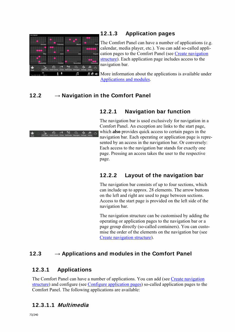
73/240
12.1.3 Application pages
The Comfort Panel can have a number of applications (e.g. calendar, media player, etc.). You can add so-called appli-cation pages to the Comfort Panel (see Create navigation structure). Each application page includes access to the navigation bar.
More information about the applications is available under Applications and modules.
12.2 → Navigation in the Comfort Panel
12.2.1 Navigation bar function
The navigation bar is used exclusively for navigation in a Comfort Panel. An exception are links to the start page, which also provides quick access to certain pages in the navigation bar. Each operating or application page is repre-sented by an access in the navigation bar. Or conversely: Each access to the navigation bar stands for exactly one page. Pressing an access takes the user to the respective page.
12.2.2 Layout of the navigation bar
The navigation bar consists of up to four sections, which can include up to approx. 28 elements. The arrow buttons on the left and right are used to page between sections. Access to the start page is provided on the left side of the navigation bar.
The navigation structure can be customised by adding the operating or application pages to the navigation bar or a page group directly (so-called containers). You can custo-mise the order of the elements on the navigation bar (see Create navigation structure).
12.3 → Applications and modules in the Comfort Panel
12.3.1 Applications
The Comfort Panel can have a number of applications. You can add (see Create navigation structure) and configure (see Configure application pages) so-called application pages to the Comfort Panel. The following applications are available:
12.3.1.1 Multimedia

74/240
Media Player - For playing back audio and video data.
Web TV - For playing back video streams.
Web Radio - For playing back audio streams.
12.3.1.2 News
Image Messaging - For recording and displaying notes.
Voice message - For recording and playing voice messages.
E-mail - For reading e-mail.
Feed Reader - For reading Feed Reader (news ticker).
12.3.1.3 Telephony
Intercom - For communicating within the house or to other Comfort Panels.
Telephone (VoIP) - For telephoning using Voice over IP (VoIP).
12.3.1.4 Home control Scene Editor - For editing and calling up scenes and sequences.
Weekly Timer - For editing weekly timers.
Calendar - For editing Yearly timers.
12.3.1.5 Security
Camera Surveillance - For displaying IP camera images.
Alarm Control Unit - For protection against unwanted visitors.
Baby phone - For monitoring a sleeping child.
12.3.1.6 Tools
Timer - For integrating an egg timer.
Alarm Clock - For integrating an alarm clock.
Data logger - For monitoring energy consumption and other data.
12.3.1.7 Einstellungen
IR remote control - For editing and calling up scenes, sequences and operating functions.

75/240
Fault and alarm messaging - For displaying and acknowledging faults
12.3.2 Software modules
There are other software modules in addition to the applications. They do not have their own page in the Comfort Panel, but provide helpful functions in the background. You must enable software modules in IPP under Comfort Panel basic settings to have access to them in the Comfort Panel (see Configure additional applications). The following software modules are available:
Simulated Presence - For recording and playing back switching processes.
Access Control - For locking individual pages with password protection.
Baby phone - For monitoring a sleeping infant.
Logic editor - For realising complex switching sequences.
Internal camera - For use in diverse applications (e.g. Baby phone/intercom)
Remote control - For remotely controlling the Comfort Panel.
12.4 → Comfort Panel design
The design of the Comfort Panel can be customised to your customer's taste. You can choose between three design versions (see Set Comfort Panel de-sign):
Blue
Black
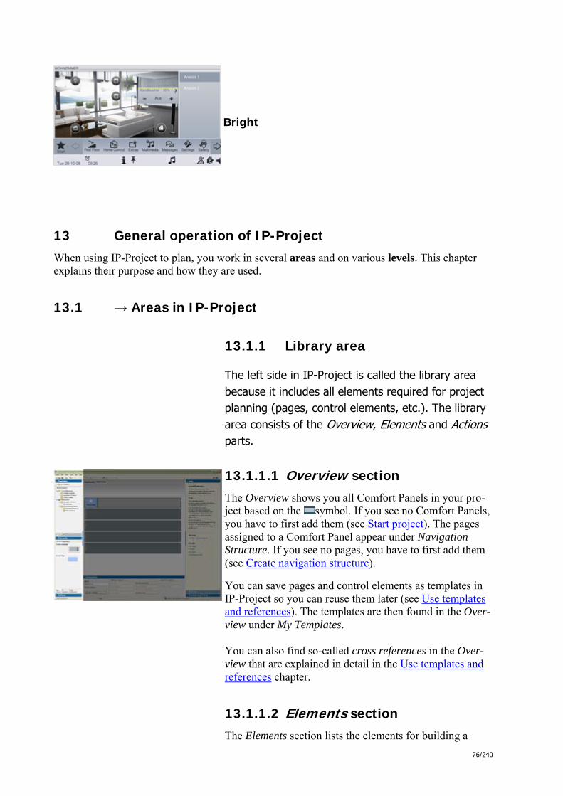
76/240
Bright
13 General operation of IP-Project
When using IP-Project to plan, you work in several areas and on various levels. This chapter explains their purpose and how they are used.
13.1 → Areas in IP-Project
13.1.1 Library area
The left side in IP-Project is called the library area because it includes all elements required for project planning (pages, control elements, etc.). The library area consists of the Overview, Elements and Actions parts.
13.1.1.1 Overview section
The Overview shows you all Comfort Panels in your pro-ject based on the symbol. If you see no Comfort Panels, you have to first add them (see Start project). The pages assigned to a Comfort Panel appear under Navigation Structure. If you see no pages, you have to first add them (see Create navigation structure).
You can save pages and control elements as templates in IP-Project so you can reuse them later (see Use templates and references). The templates are then found in the Over-view under My Templates. You can also find so-called cross references in the Over-view that are explained in detail in the Use templates and references chapter.
13.1.1.2 Elements section
The Elements section lists the elements for building a
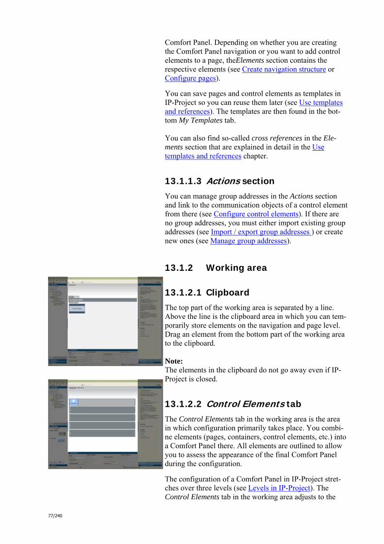
77/240
Comfort Panel. Depending on whether you are creating the Comfort Panel navigation or you want to add control elements to a page, theElements section contains the respective elements (see Create navigation structure or Configure pages).
You can save pages and control elements as templates in IP-Project so you can reuse them later (see Use templates and references). The templates are then found in the bot-tom My Templates tab. You can also find so-called cross references in the Ele-ments section that are explained in detail in the Use templates and references chapter.
13.1.1.3 Actions section
You can manage group addresses in the Actions section and link to the communication objects of a control element from there (see Configure control elements). If there are no group addresses, you must either import existing group addresses (see Import / export group addresses ) or create new ones (see Manage group addresses).
13.1.2 Working area
13.1.2.1 Clipboard
The top part of the working area is separated by a line. Above the line is the clipboard area in which you can tem-porarily store elements on the navigation and page level. Drag an element from the bottom part of the working area to the clipboard. Note: The elements in the clipboard do not go away even if IP-Project is closed.
13.1.2.2 Control Elements tab
The Control Elements tab in the working area is the area in which configuration primarily takes place. You combi-ne elements (pages, containers, control elements, etc.) into a Comfort Panel there. All elements are outlined to allow you to assess the appearance of the final Comfort Panel during the configuration.
The configuration of a Comfort Panel in IP-Project stret-ches over three levels (see Levels in IP-Project). The Control Elements tab in the working area adjusts to the
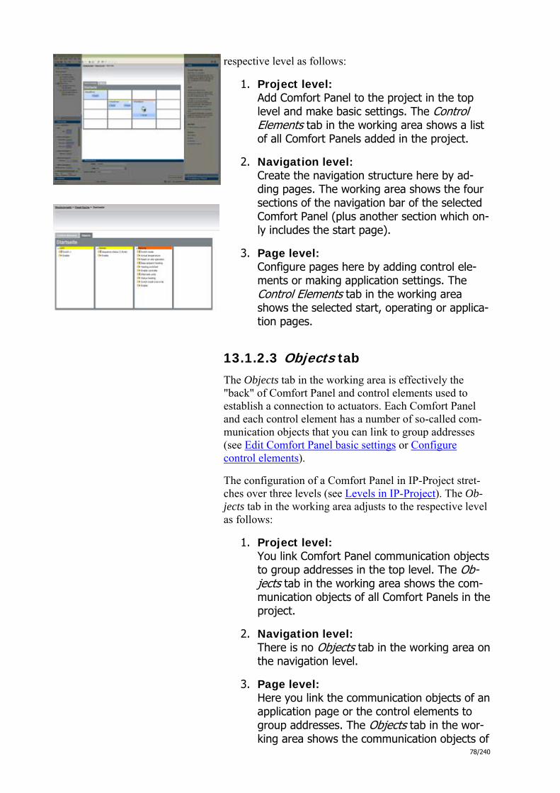
78/240
respective level as follows:
1. Project level: Add Comfort Panel to the project in the top level and make basic settings. The Control Elements tab in the working area shows a list of all Comfort Panels added in the project.
2. Navigation level: Create the navigation structure here by ad-ding pages. The working area shows the four sections of the navigation bar of the selected Comfort Panel (plus another section which on-ly includes the start page).
3. Page level: Configure pages here by adding control ele-ments or making application settings. The Control Elements tab in the working area shows the selected start, operating or applica-tion pages.
13.1.2.3 Objects tab
The Objects tab in the working area is effectively the "back" of Comfort Panel and control elements used to establish a connection to actuators. Each Comfort Panel and each control element has a number of so-called com-munication objects that you can link to group addresses (see Edit Comfort Panel basic settings or Configure control elements).
The configuration of a Comfort Panel in IP-Project stret-ches over three levels (see Levels in IP-Project). The Ob-jects tab in the working area adjusts to the respective level as follows:
1. Project level: You link Comfort Panel communication objects to group addresses in the top level. The Ob-jects tab in the working area shows the com-munication objects of all Comfort Panels in the project.
2. Navigation level: There is no Objects tab in the working area on the navigation level.
3. Page level: Here you link the communication objects of an application page or the control elements to group addresses. The Objects tab in the wor-king area shows the communication objects of
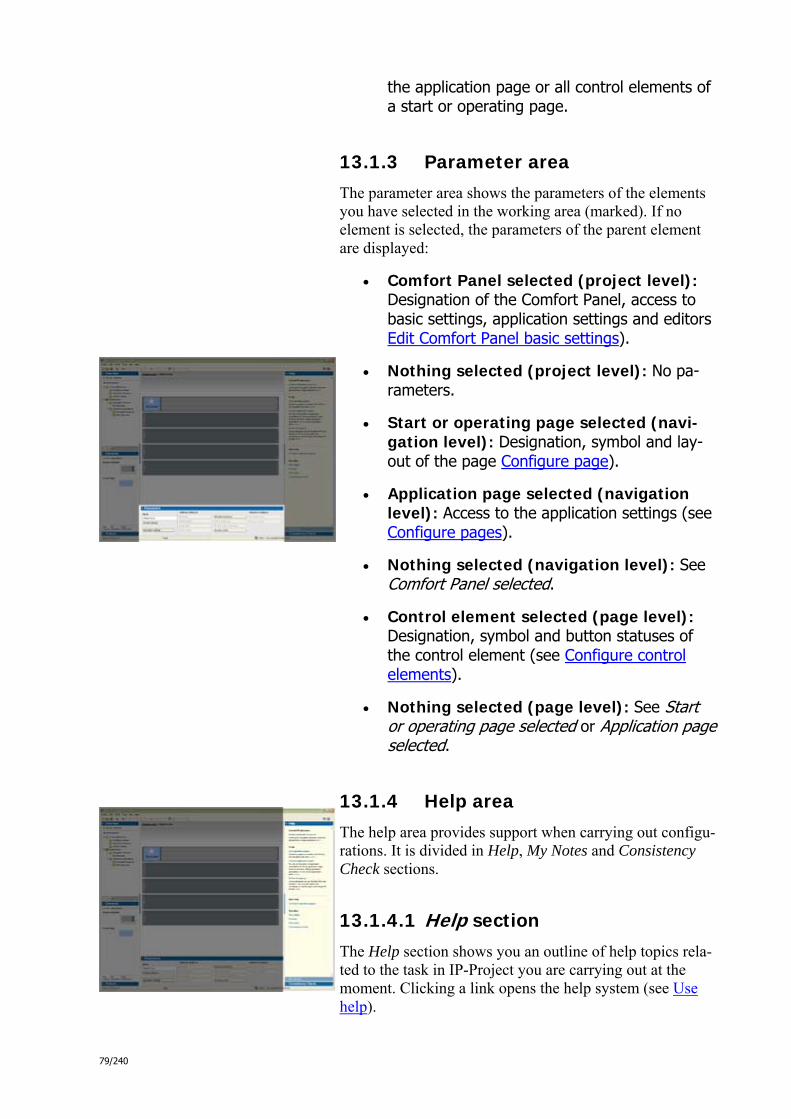
79/240
the application page or all control elements of a start or operating page.
13.1.3 Parameter area
The parameter area shows the parameters of the elements you have selected in the working area (marked). If no element is selected, the parameters of the parent element are displayed:
Comfort Panel selected (project level): Designation of the Comfort Panel, access to basic settings, application settings and editors Edit Comfort Panel basic settings).
Nothing selected (project level): No pa-rameters.
Start or operating page selected (navi-gation level): Designation, symbol and lay-out of the page Configure page).
Application page selected (navigation level): Access to the application settings (see Configure pages).
Nothing selected (navigation level): See Comfort Panel selected.
Control element selected (page level): Designation, symbol and button statuses of the control element (see Configure control elements).
Nothing selected (page level): See Start or operating page selected or Application page selected.
13.1.4 Help area
The help area provides support when carrying out configu-rations. It is divided in Help, My Notes and Consistency Check sections.
13.1.4.1 Help section
The Help section shows you an outline of help topics rela-ted to the task in IP-Project you are carrying out at the moment. Clicking a link opens the help system (see Use help).

80/240
13.1.4.2 Consistency Check section
The Consistency Check section is used to check for incon-sistencies in your project. You can check the current view (Check current view), the current Comfort Panel (Check Comfort Panel) or the overall project (Check project).
Any inconsistencies found are listed in the Consistency Check section as follows:
Error: Serious inconsistencies that must be resolved before the project is transferred to the Com-fort Panel.
Notes: Less serious inconsistencies that should be re-solved, but do not affect functionality.
More information about the consistency check is available under Perform consistency check!
13.2 → Levels in IP-Project
The configuration of a Comfort Panel in IP-Project stret-ches over three levels: Project level, navigation level and page level. Each level is has its own special tasks. Wor-king and library areas therefore adjust based on the respec-tive level.
13.2.1 Project level:
You manage your project in the top level. The working area displays a list of all Comfort Panels in the project. Typical tasks on this level include:
Adding and designating new Comfort Panels in the project
Editing Comfort Panel basic settings
Importing group addresses
Transferring from projects to a Comfort Panel
Linking Comfort Panel communication objects to group addresses

81/240
13.2.2 Navigation level:
This level is used to create a Comfort Panel navigation structure. The working area shows the four sections of the navigation bar of the selected Comfort Panel (plus another section which only includes the start page). Typical tasks on this level include:
Adding and designating pages and containers
Changing page and container symbols
13.2.3 Page level:
This level is used to configure Comfort Panel start, operating and application pages. The working area shows the selected start, operating or application pages. Typical tasks on this level include:
Adapting the layout of operating pages
Adding and designating control elements on operating pages
Changing control element labels on operating pages
Setting application parameters on application pages
Linking control element communication ob-jects to group addresses
Linking application page communication ob-jects to group addresses
13.3 → Navigation in IP-Project
13.3.1 Navigate between levels
The configuration of a Comfort Panel in IP-Project stret-ches over three levels: Project level, navigation level and page level (see above "Levels in IP Project"). You can switch between these three levels at any time. The path at the top of the working area indicates where you are at the moment.
If you wish to go to a deeper level (e.g. from project to navigation level), you have the following options:

82/240
1. Double-click the required element.
2. Select Edit in the context menu of the required element (right click).
3. Mark the required element and select Edit Se-lected in the menu under Edit.
4. Select the required element and press ENTER to confirm your entry.
Use the path at the top of the working area to go to a hig-her level (e.g. from the navigation to project level).
13.3.2 Navigate to other elements
If you wish, for instance, to navigate to another page in another Comfort Panel, use the methods described above for navigating between levels: First navigate up to the pro-ject level and then down again to the page level in the new Comfort Panel.
However, the Overview section in the library area to the right allows you to navigate directly. You have an over-view of all pages and can navigation by double-clicking the link to the respective page directly.
13.3.2.1
13.3.3 Navigating via keypad
You can use the keypad in IP Project to navigate between levels, windows and elements. The keypad focus can be recognised by a framing of the focused element.
If you would like to navigate between windows, use the tab key. The keypad focus then jumps to the next window, or with Ctrl+Tab key, to the previous window. The order of the areas is as follows:
1. Library: Overview
2. Library: Elements
3. Library: Actions
4. Path
5. Working area
6. Parameter area

83/240
7. Help area
You can move from one element to the next within the areas, using the arrow keys (e.g. between the operating elements on a page).
The navigation between the levels in the working area is also possible via keypad: Using the enter key, you can go one processing level lower for the highlighted element (e.g. one page on navigation level). You can go one level higher using the escape key. In the library area, the enter key opens a highlighted ele-ment in the working area (e.g. for pages in the overview) or opens a dialog for additional settings (e.g. for group addresses). In the help area, the enter key opens help chap-ters if the keypad focus is on a link.
The Alt key shows the abbreviations for the menu access per keypad. Combine the underlined letters with the Alt key to open a menu category.
13.4 → The context menu
You can call up a context menu for each marked element in IP-Project by right-clicking. The context menu displays all functions allowed for the marked element.
14 Add and edit elements
Drag and Drop is used to a great extent for configuration in IP-Project. You can drag and drop nearly any element (e.g. pages or control elements). This chapter describes the configuration options in IP-Project available to you using this feature.

84/240
14.1 → Add elements from the library
14.1.1 Available elements
All available elements are listed in the IP-Project library area.
The Actions section lists group addresses that you have to either create yourself or import.
The Elements section lists the elements for building a Comfort Panel. The elements are strictly specified. The list under Elements depends on the level in IP-Project you are currently in (see Levels in IP-Project):
14.1.1.1 Project level:
No elements available. Comfort Panels are added via the menu under Project > Insert Comfort Panel (see Manage project).
14.1.1.2 Navigation level:
Operating pages (Control Elements tab) - see Add and edit pages.
Open containers (Control Elements tab) - see Add and edit containers.
Application pages (Applications tab) - see Add and edit pages.
Fixed containers (Applications tab) - see Add and edit containers.
14.1.1.3 Page level:
Control elements (Control Elements tab) - see Add and edit operating pages.
Compact applications (Applications tab, for start pages only) - see Add and edit pages.
Links (for start pages only) - see Add and edit start pages.

85/240
14.1.2 Using Drag and Drop to add
Elements are added via Drag and Drop from the library area to the working area.
If you wish to add an element, please proceed as follows:
1. Move the mouse over an element in the library area you want to add.
2. Left-click and hold.
3. Drag the element to the position in the wor-king area where you want to put the element.
4. Drop the element.
Note: For pages and containers, you can drag and drop elements in open fields only. You can put elements anywhere on the navigation bar (even between two other elements).
14.2 → Select (mark) elements
14.2.1 Use and purpose of selecting
Elements are selected by moving your cursor over the required element and clicking once. A blue frame or background then high-lights the selected element.
Once you have selected (marked) an element, it is read for other editing steps. The parameter area, for instance, shows the parame-ters of the element selected in the working area.
14.2.2 Select several elements
If you wish to select several elements in a row or column, please proceed as follows:
1. Select the first element (example shown: Lamp 1).
2. Hold down the SHIFT button and select the last ele-ment (example shown: Lamp 3).

86/240
If you wish to add several elements individually to the existing selection, hold down the CTRL button and select additional ele-ments (example shown: Lamp 3).
If you wish to select all elements in a view, use the shortcut CTRL+A.
You can also create a frame in the working area to select several elements:
1. Move the cursor to a position where there are no elements (e.g. white area outside a page).
2. Left-click and drag a frame around the desired ele-ments.
3. Drop the frame.
All elements within in the frame are now selected.

87/240
14.3 → Move elements
You can drag and drop elements within the working area or within the Overview and Actions sections (library area).
Please proceed as follows:
1. Move the cursor over the element you want to move.
2. Left-click and hold.
3. Drag the element to the position where you want to put the element.
4. Drop the element.
14.4 → Cut, copy, paste elements
14.4.1 Cut
You can use the "cut" function to can delete selected elements and at the same time, copy elements to the Windows clipboard to then reinsert them somewhere else. If you wish to cut an element, please proceed as follows:
1. Select the element you want to cut (see Select elements).
2. Cut the element by...
o ... Clicking the button in the toolbar, or...
o ... Selecting the Cut option in the context menu (right-click), or...
o ... Selecting the Cut option in the Edit menu item, or...
o ... Using the shortcut CTRL+X.

88/240
14.4.2 Copy
You can use the "Copy" function to copy elements to the Win-dows clipboard without deleting them. You can then insert them somewhere else and thus duplicate the original element. If you wish to copy an element, please proceed as follows:
1. Select the element you want to copy (see Select elements).
2. Copy the element to the clipboard by...
o ... Clicking the button in the toolbar, or...
o ... Selecting the Copy option in the context menu (right-click), or...
o ... Selecting the Copy option in the Edit me-nu item, or...
o ... Using the shortcut CTRL+C.
14.4.3 Paste (from the Windows clipboard)
You can use the "Paste" function to reinsert elements from the Windows clipboard that you previously cut or copied. With the "Paste" function, the element remains in the clipboard and al-lows you to repeat the function as often as needed.
If you wish to add an element, please proceed as follows:
1. Select the position where you want to paste the element (e.g. empty field of a page).
2. Paste the element from the clipboard by...
o ... Clicking the button in the toolbar, or...
o ... Selecting the Paste option in the context menu (right-click), or...
o ... Selecting the Paste option in the Edit menu item, or...
o ... Using the shortcut CTRL+V.
Note: Please note that you can only paste elements to the required position that are allowed. For instance, you cannot copy a com-pact application from the start page and paste it into an opera-ting page. Compact applications can be inserted in start pages only.
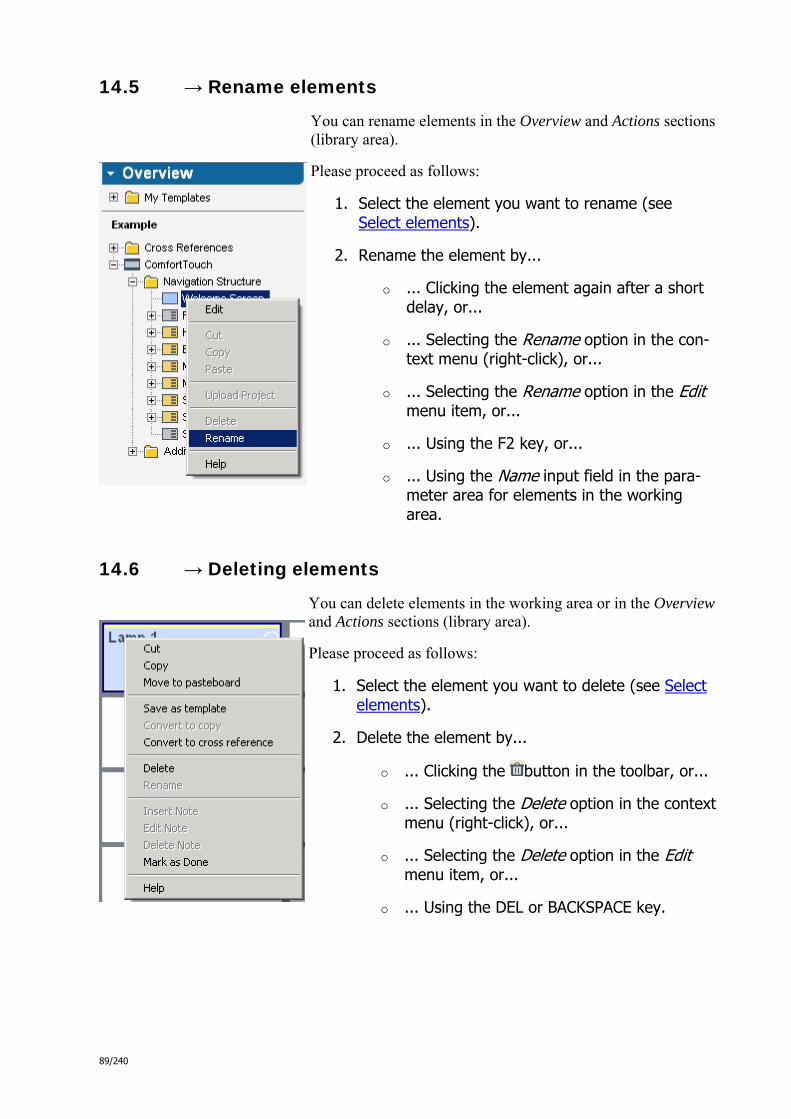
89/240
14.5 → Rename elements
You can rename elements in the Overview and Actions sections (library area).
Please proceed as follows:
1. Select the element you want to rename (see Select elements).
2. Rename the element by...
o ... Clicking the element again after a short delay, or...
o ... Selecting the Rename option in the con-text menu (right-click), or...
o ... Selecting the Rename option in the Edit menu item, or...
o ... Using the F2 key, or...
o ... Using the Name input field in the para-meter area for elements in the working area.
14.6 → Deleting elements
You can delete elements in the working area or in the Overview and Actions sections (library area).
Please proceed as follows:
1. Select the element you want to delete (see Select elements).
2. Delete the element by...
o ... Clicking the button in the toolbar, or...
o ... Selecting the Delete option in the context menu (right-click), or...
o ... Selecting the Delete option in the Edit menu item, or...
o ... Using the DEL or BACKSPACE key.

90/240
14.7 → Change element symbols
You can change the following symbols:
Navigation bar symbol from operating pages that are not in a container
Watermarks from operating pages in a container (if watermark symbols are enabled, see Set Comfort Panel design)
Navigation bar symbols from open containers
Watermarks from scene control elements (if watermark symbols are enabled, see Set Comfort Panel design)
Button symbols from control elements (if Symbol is selected as the label type - see Configure control elements)
You can select symbols in the respective parameter area using the Browse button directly or in the dialog for advanced settings. Click the Advanced Settings button of the respective parameter area to open.
14.8 → Change element parameters
Each element in the working area has certain parameters. The most important parameters are displayed in the para-meter area for the selected element (e.g. the page title of an operating page). You can change other parameters as follows:
For the advanced settings of a selected Com-fort Panel, please click the Default Settings button in the parameter area (see Edit Com-fort Panel basic settings).
For the settings of a selected application page, please click the Advanced Settings but-ton in the parameter area (see Configure ap-plication pages).
For the advanced settings of a selected control element, please click the Advanced Settings button in the parameter area (see Configure control elements).

91/240
15 Use Help
Drag and Drop is used to a great extent for configuration in IP-Project. You can drag and drop nearly any element (e.g. pages or control elements). This chapter describes the configuration options in IP-Project available to you using this feature.
15.1 → Use help area in IP-Project
15.1.1 Open help area
Open the help area by clicking the blue middle area on the right side in IP-Project.
15.1.2 Use Help in the help area
You can find a summary of help topics directly related to your current task in configuring a Comfort Panel in IP-Project in the IP-Project help area on the right side under Help. You can find the following information:
This project planning stage Which configuration step is displayed in the current view of the working area is briefly explained.
Tasks in this project planning stage The most important tasks of the current configuration step are listed and briefly explained under Tasks in this project planning stage. It is recommended to fully implement these steps.
Next project planning stage The next step recommended in configuring a Comfort Panel appears.
See also Related topics that may also be of interest to you are listed under See also.
If you want to learn more about a topic in the help area, click the mo-re... link. This takes you to a complete description within the help system.
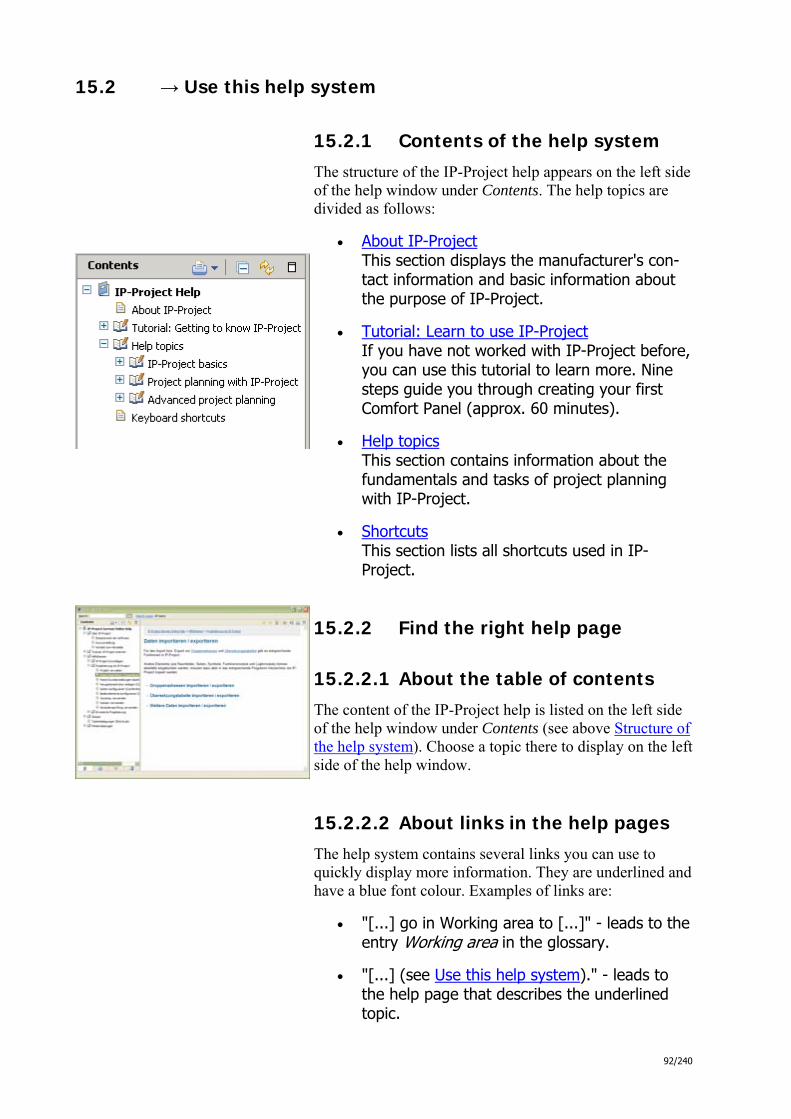
92/240
15.2 → Use this help system
15.2.1 Contents of the help system
The structure of the IP-Project help appears on the left side of the help window under Contents. The help topics are divided as follows:
About IP-Project This section displays the manufacturer's con-tact information and basic information about the purpose of IP-Project.
Tutorial: Learn to use IP-Project If you have not worked with IP-Project before, you can use this tutorial to learn more. Nine steps guide you through creating your first Comfort Panel (approx. 60 minutes).
Help topics This section contains information about the fundamentals and tasks of project planning with IP-Project.
Shortcuts This section lists all shortcuts used in IP-Project.
15.2.2 Find the right help page
15.2.2.1 About the table of contents
The content of the IP-Project help is listed on the left side of the help window under Contents (see above Structure of the help system). Choose a topic there to display on the left side of the help window.
15.2.2.2 About links in the help pages
The help system contains several links you can use to quickly display more information. They are underlined and have a blue font colour. Examples of links are:
"[...] go in Working area to [...]" - leads to the entry Working area in the glossary.
"[...] (see Use this help system)." - leads to the help page that describes the underlined topic.

93/240
You can use the and buttons on the top right of the help window to navigate forward and backward link in a web browser.
15.2.2.3 About the help system search function
You can use the search function to search in the help sys-tem for specific terms.
Enter a term in the search field above the table of contents and click GO. The area on the left then switches from the Contents tab to the Search Results tab. The search results are listed. The top entry corresponds to the best match for your search term. Select a search result.
The area on the right the displays the chapter for the respective search result. If the complete search term is found in the content, it is marked in colour.
Note: Click the button at the bottom of the area on the left to return to the table of contents.
15.2.2.4 About the context menu in IP-Project
The help can be called up for each selectable element (see Select element) in the context menu.
Select the element for which you need help and select Help. The help window opens and displays the help page about the selected element.

94/240
15.2.3 Use bookmarks
You can bookmark help pages to call them up quickly again later.
15.2.3.1 Create bookmark
Open the help page for which you want to create a book-mark and then click the button on the top right of the help window. The help page is then listed in your book-marks.
15.2.3.2 Call bookmarks
Use the button at the bottom of the help window on the left to display the list of bookmarks. Select a bookmark to display the bookmarked help page.
15.2.3.3 Delete bookmark
Use the button at the bottom of the help window on the left to display the list of bookmarks. Use the button to delete a selected bookmark.
Note: Click the button at the bottom of the area on the left to return to the table of contents.
16 Project planning with IP-Project
Find here detailed information about basic project planning activities.
16.1 Help pages in this chapter
Manage project
Import / export data
Edit Comfort Panel basic settings
Create navigation structure (Comfort Panel)
Configure pages (Comfort Panel)
Configure control elements (Comfort Panel)
Use preview
Use notes

95/240
Perform consistency check
17 Manage project
You can define the configuration for one or more Comfort Panels in a project. Only one project can be open in IP-Project at one time. The online help describes basic project management in IP-Project - from creating new projects to saving and transferring finished projects to a Comfort Panel in the network.
17.1 → Start project
17.1.1 Create new project
Go to Project > New in the menu or click in the toolbar to create a new project. Enter a project name in the dialog under Project. Because IP-Project sug-gests this as the file name when saving, a meaning-ful project name is already suggested. If you wish, you can save additional information about the project in the Project and Customer areas. You can also save additional information later (see Edit project information). Remember that only one project can be open at any one time. If you already have a project open, you are prompted to save the changes. You can create one or more Comfort Panels in the Comfort Panel area. Select the Comfort Panel type (e.g. "Comfort Comfort Panel"), enter a Comfort Pa-nel name (e.g. "Comfort Panel Kitchen") and if ne-cessary, information about the installation location (e.g. "next to the refrigerator"). You can use the Add button to add additional Com-fort Panels. You can also add additional Comfort Pa-nels later (see Insert Comfort Panel).

96/240
17.1.2 Open project
You can open an existing project from any storage medium via Project > Open... in the menu or by cli-cking in the toolbar. Select an IP-Project file in the dialog (.ipp extension) and confirm your selection by clicking Open. Remember that only one project can be open at any one time. If you already have a project open, you are prompted to save the changes.
17.1.3 Insert Comfort Panel
You can add additional Comfort Panels at any time via Project > Insert Comfort Panel in the menu or by clicking in the Overview section of the library area.
17.1.4 Download project from Comfort Panel (Commissioning)
You can download a project from a Comfort Panel via Project > Download Project in the menu and by clicking in the toolbar. Select the Comfort Panel that you want to download from your project in the dialog under Choose a Comfort Panel. You can then select between downloading from the Comfort Panel via a network connection or a mo-bile storage medium (USB stick, memory card).
If you want to use the network option, ensure that a net-work connection to the Comfort Panel exists. Select the From device option and then select the device from the list. You can use the identification function to locate the correct Comfort Panel (see Identify Comfort Panel). Click Download Project to start the transfer.
If you want to use a storage medium, select the Load from file system option and enter a storage location. Click Download project from ...Upload to save the file to the

97/240
storage medium. For this, you need to have loaded the con-figuration file from the Comfort Panel. To do this, go do the desired Comfort Panel device and plug in the storage medium. Activate the Comfort Panel and select the export function in the navigation bar under System > Export. The configuration for the Comfort Panel is saved as a file with the extension .zip to the selected storage location.
Note: The downloading of a configuration may only be done to a newly created, empty project, otherwise, existing group addresses may possibly get lost.
17.2 → Edit project information
You can review and edit information about the project (Project tab) and the customer (Customer tab) via Project > Project Information in the menu. The History tab allows you to manually create a change history that you can use to make tracking changes in the project easier. If you want to display the change history when closing a project, enable the checkbox Show dialog "Project History" on exit.
IP-Project automatically saves important information, for instance the number of data points, in the Statistics tab.
17.3 → Finish project
17.3.1 Save project / Save project as
You can save the changes in the open project via Project > Save or Project > Save as... in the menu. Select a folder and file name in the Save as dialog and click Save.

98/240
17.3.2 Transfer project to Comfort Panel (Commissioning)
You can transfer a project to a Comfort Panel via Project > Upload Project in the menu and by clicking
in the toolbar. Select the Comfort Panel from your project that you want to transfer to in the dialog un-der Choose a Comfort Panel. You can transfer the project to the Comfort Panel using a network connec-tion or a mobile storage medium (USB stick, memory card) under Choose a device. If you want to use the network option, ensure that a network connection to the Comfort Panel exists. Se-lect the To device option and then select the device from the list. You can use the identification function to locate the correct Comfort Panel (see Identify Comfort Panel). Click Upload to start the transfer. If you want to use a storage medium, select the Save to file system option and enter a storage location. Click Upload to save the file to the storage medium. The configuration for the Comfort Panel is saved as a file with the extension .zip to the selected storage location. Then go do the required Comfort Panel de-vice and plug in the storage medium. Activate the Comfort Panel and select the zip file in the navigation bar under System > Import.
17.3.3 Identify Comfort Panel
The identification function helps you find a specific Comfort Panel in the network. This function is also available when transferring configurations. If you want to use the identification function, please ensure that a network connection to the Comfort Panel exists.

99/240
Choose a Comfort Panel from the list that you want to identify. You can play a war-ning signal either of a certain length or until confirmation at the Comfort Panel. Click Identify and you can locate the Comfort Panel on the basis of the warning tone.
17.3.4 Close Project
Close the open project via Project > Close project in the menu, close the entire program via Project > Close IP-Project.
If you have enabled the Show dialog "Project History" on exit checkbox via Project > Project Information... in the History tab, you can review and edit the change history when exiting.
18 Import / export data
There are corresponding functions in IP-Project for importing or exporting group addresses and translation tables.
Other elements (e.g. room images, pages, symbols, function modules and logic modules) can also be integrated, but must be copied to the corresponding program directory of IP-Project.
18.1 → Import / export group addresses
18.1.1 Import group addresses
The dialog for importing group addresses is available via Project > Import group addresses in the menu. Group addresses can be loaded into IP-Project from any directory or drive. Select a file in the dialog and load it into IP-project by clicking Open.
Please note:
Unregistered group addresses cannot be im-ported.
Imported group addresses cannot be changed in IP-Project.
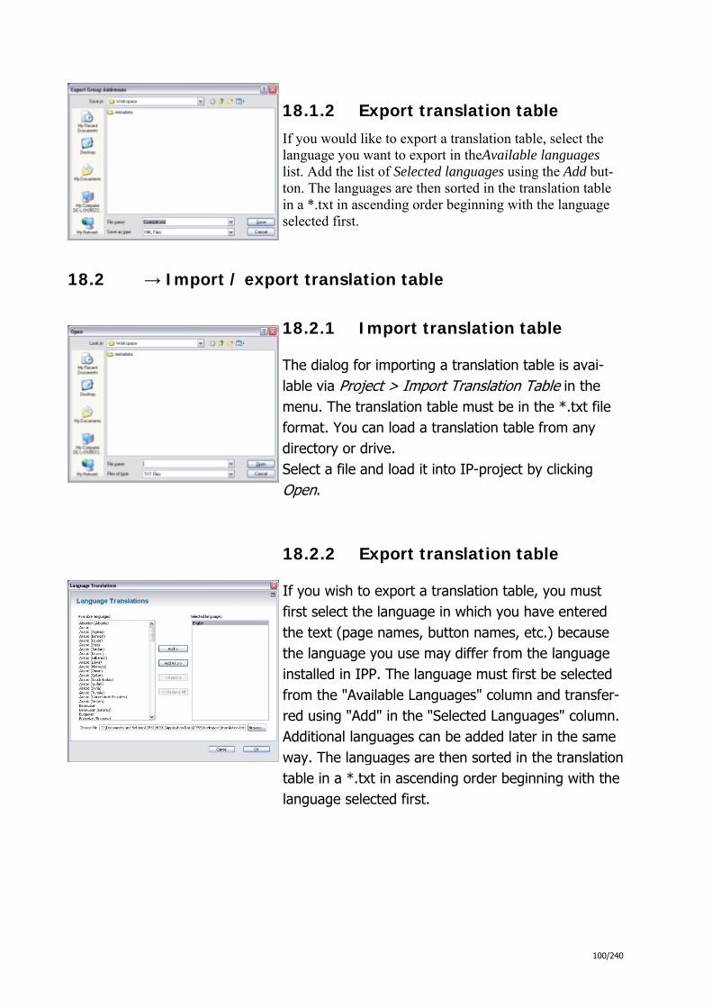
100/240
18.1.2 Export translation table
If you would like to export a translation table, select the language you want to export in theAvailable languages list. Add the list of Selected languages using the Add but-ton. The languages are then sorted in the translation table in a *.txt in ascending order beginning with the language selected first.
18.2 → Import / export translation table
18.2.1 Import translation table
The dialog for importing a translation table is avai-lable via Project > Import Translation Table in the menu. The translation table must be in the *.txt file format. You can load a translation table from any directory or drive. Select a file and load it into IP-project by clicking Open.
18.2.2 Export translation table
If you wish to export a translation table, you must first select the language in which you have entered the text (page names, button names, etc.) because the language you use may differ from the language installed in IPP. The language must first be selected from the "Available Languages" column and transfer-red using "Add" in the "Selected Languages" column. Additional languages can be added later in the same way. The languages are then sorted in the translation table in a *.txt in ascending order beginning with the language selected first.
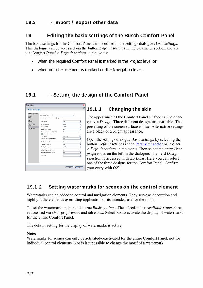
101/240
18.3 → Import / export other data
19 Editing the basic settings of the Busch Comfort Panel
The basic settings for the Comfort Panel can be edited in the settings dialogue Basic settings. This dialogue can be accessed via the button Default settings in the parameter section and via via Comfort Panel > Default settings in the menu:
when the required Comfort Panel is marked in the Project level or
when no other element is marked on the Navigation level.
19.1 → Setting the design of the Comfort Panel
19.1.1 Changing the skin
The appearance of the Comfort Panel surface can be chan-ged via Design. Three different designs are available. The presetting of the screen surface is blue. Alternative settings are a black or a bright appearance.
Open the settings dialogue Basic settings by selecting the button Default settings in the Parameter sector or Project > Default settings in the menu. Then select the entry User preferences on the left in the dialogue. The field Design selection is accessed with tab Basis. Here you can select one of the three designs for the Comfort Panel. Confirm your entry with OK.
19.1.2 Setting watermarks for scenes on the control element
Watermarks can be added to control and navigation elements. They serve as decoration and highlight the element's overriding application or its intended use for the room.
To set the watermark open the dialogue Basic settings. The selection list Available watermarks is accessed via User preferences and tab Basis. Select Yes to activate the display of watermarks for the entire Comfort Panel.
The default setting for the display of watermarks is active.
Note: Watermarks for scenes can only be activated/deactivated for the entire Comfort Panel, not for individual control elements. Nor is it it possible to change the motif of a watermark.

102/240
19.2 → Setting the language of the Comfort Panel
19.2.1 Setting the language of the Comfort Panel
19.2.1.1 System languages
The Comfort Panel is supplied with 22 predefined System languages in which all fixed system texts are defined. The languages are: Arabic, Chinese, German, Danish, English, Estonian, Fin-nish, French, Greek, Hebrew, Italian, Latvian, Lithuanian, Dutch, Norwegian, Polish, Russian, Swedish, Slovakian, Spanish, Czech, Turkish.
The system language of the Comfort Panel is changed in dialogue Basic settings and the sector of User preferences via tab Basis in the selection list System language. It can also be set by the user in the Comfort Panel via Sys-tem > System Settings & System Settings under System language.
19.2.1.2 User-defined languages
In addition, up to 135 User-defined languages can be created. They refer to texts you have defined in your pro-ject and have not been supplied by the system (e.g. label-ling of buttons, operating pages, etc.). User-defined langu-ages are defined in theTranslation table. There all texts for the above-mentioned system languages and, if required, a further 234 languages are entered (see Editing translation table.
You can change the user-defined language of the Comfort Panel the User preferences area via the Basis tab in the User language selection list. It can also be set by the user in the Comfort Panel via Sys-tem > System Settings & System Settings under User lan-guage.
Note: In contrast to the Comfort Panel the IP project software can only be operated in German or English. The system language is set during the installation of the IP project and cannot be subsequently altered.
19.2.2 Editing the translation table
Translation tables for User-defined languages can be exported from the IP project for editing.
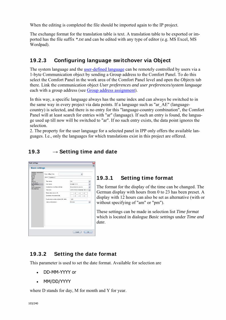
103/240
When the editing is completed the file should be imported again to the IP project.
The exchange format for the translation table is text. A translation table to be exported or im-ported has the file suffix *.txt and can be edited with any type of editor (e.g. MS Excel, MS Wordpad).
19.2.3 Configuring language switchover via Object
The system language and the user-defined language can be remotely controlled by users via a 1-byte Communication object by sending a Group address to the Comfort Panel. To do this select the Comfort Panel in the work area of the Comfort Panel level and open the Objects tab there. Link the communication object User preferences and user preferences/system language each with a group address (see Group address assignment).
In this way, a specific language always has the same index and can always be switched to in the same way in every project via data points. If a language such as "ar_AE" (language-country) is selected, and there is no entry for this "language-country combination", the Comfort Panel will at least search for entries with "ar" (language). If such an entry is found, the langua-ge used up till now will be switched to "ar". If no such entry exists, the data point ignores the selection. 2. The property for the user language for a selected panel in IPP only offers the available lan-guages. I.e., only the languages for which translations exist in this project are offered.
19.3 → Setting time and date
19.3.1 Setting time format
The format for the display of the time can be changed. The German display with hours from 0 to 23 has been preset. A display with 12 hours can also be set as alternative (with or without specifying of "am" or "pm").
These settings can be made in selection list Time format which is located in dialogue Basic settings under Time and date.
19.3.2 Setting the date format
This parameter is used to set the date format. Available for selection are
DD-MM-YYYY or
MM/DD/YYYY
where D stands for day, M for month and Y for year.

104/240
These settings can be made in selection list Date format which is located in dialogue Basic set-tings under Time and date.
19.3.3 Send/receive time
The Comfort Panel has an internal Date/Time module. The following can be selected via para-meter Send and receive Time/Date,
whether time and date are to be used only internally (no send and no receive),
whether the Comfort Panel is to synchronize further KNX components in the system (sending, but not receiving) or
whether the Comfort is to be updated with a KNX-DCF module (receiving, but not sending).
If you select one of the last two options you can synchronize the time and date via a Communi-cation object by sending a Group address to or from the Comfort Panel. To do this select the Comfort Panel in the work area of the Comfort Panel level and open the Objects tab there. Link the communication objects Time and date / time and Time and date / date with a group address (see Group address assignment).
These settings can be made in selection list Send and receive time /date which is located in dialogue Basic settings under Time and date.
19.3.4 Setting the time zone
The local time zone (e.g. GMT+1 time zone Berlin, Paris) can be set in the selection list Time zone in dialogue Basic settings under Time and date.
19.3.5 Configuring time synchronisation
The synchronisation can be configured via external time generators in dialogue Basic settings under tab Basis. This enables you to ensure that all Comfort Panels in one home display the same time.
19.3.5.1 Activating / deactivating synchronisation
Parameter Time synchronisation is used for setting whether the date and time of the Comfort Panel are to be synchronised with an external time generator.
Select KNX if synchronisation is to take place via a KNX-DCF module. Select NTP if synchro-nisation is to take place via a Time server. in the Internet with the aid of the NTP protocol. If no synchronisation is required please select No synchronisation.
19.3.5.2 Setting time server URL
The Time servers for synchronising the date and time of the Comfort Panel is set via parameter Primary time server URLand Secondary time server URL.

105/240
The German institute Physikalisch-Technische Bundesanstalt (PTB) makes two time servers available.
ptbtime1.ptb.de --> 192.53.103.108
ptbtime2.ptb.de --> 192.53.103.104
The second time server comes in when the first one fails.
19.3.5.3 Setting the synchronisation interval
The synchronisation interval is set via parameter Synchronization interval .
If possible, leave the interval on the maximum value of 1440 minutes unless there are specific reasons for reducing it. This holds the network load to a minimum.
19.3.5.4 Forcing synchronisation
Via parameter Deviation time in the Properties 2 tab, you set the deviation time at which the date and time synchronisation is to be forced even when synchronisation is deactivated. Date and time are synchronised only when the set deviation time has been reached. Any time bet-ween 60 and 300 seconds can be selected.
19.3.6 Setting time and date manually (Tab Properties 2)
Date and time can be entered manually via parameter Date and Time. Both parame-ters can be modified subsequently in the Comfort Panel under Settings.
19.3.7 Entering coordinates for the astro function (Tab Properties 2)
Via parameter Longitude and Latitude you can enter the longitude and latitude. This is required for the Astro function of the Weekly timers.
Longitude indicates the longitude of -180° (West) to +180° (East). It is specified in decimal degrees. i.e. minutes and seconds are shown as decimal places. One degree corresponds to 60 minutes and one minute to 60 seconds. The entry is made using the decimal system in the form of ddd.dddddd (e.g. 7.565278).
Latitude indicates the latitude of -90° (South) to +90° (North). It is specified in decimal de-grees. i.e. minutes and seconds are shown as decimal places. One degree corresponds to 60 minutes and one minute to 60 seconds. The entry is made using the decimal system in the form of ddd.dddddd (e.g. 51.445833).
19.3.8 Setting the user level (Tab Properties 2)
Parameter User level is used to set whether every user can modify the time in the Comfort Pa-

106/240
nel or whether only selected persons are permitted to do so. If you wish to attach Access pro-tection to the time setting, then select a User level between 1 and 8, with level 8 having the highest access protection.
Note: Please note that you must first create the user levels in the editor for the Access protection be-fore they can be assigned!
19.4 → Setting screen saver and time intervals
19.4.1 Setting time interval for return to the start page
By default the Comfort Panel automatically returns to the welcome screen 60 seconds after the last press of a button. You can change this time period. You can deactivate this function, which has the effect that the Comfort Panel re-mains on the current screen view up to the next press of a button.
In dialogue Basic settings select the entry User preferencesand there the tab Maintenance. This view contains the checkbox Activate automatic return to welcome screen, which is used to set whether the Comfort Panel is to auto-matically return to the start page after a set time period without an input from the user.
The duration of this period can be set in field Return after (10, 3600). It is specified in seconds.
Note: The time period for the return to the start page usually re-ceives a lower value than the period for activating the Screen saver; however, both values can be set indepen-dently.
19.4.2 Setting time interval for return to the screen saver
You can set whether the screen saver is to switch itself on after a defined time period when the Comfort Panel is acti-vated for this period.
In the dialogue Basic settings navigate to the view Screen saver. In the selection field Show screen saver you can select time intervals from 5 to 120 minutes. If the screen saver should not switch itself on, select No screen saver.

107/240
19.4.3 Setting time interval for deactivating the display
After expiry of a specified time the display of the Comfort Panel can be switched off complete-ly. Here a time period from the last actuation of the Comfort Panel up to the deactivation of the display must be set. The two timers for the screen saver (see above) and the deactivation of the display start simultaneously. If the display is deactivated it will turn itself on again after rene-wed actuation.
Time intervals can be set in dialogue Basic settings in view Screen saver in the selection list Stop screen saver and turn off display.
Note: It is advisable for the screen saver to activate itself first and then after the expiry of a specified time the display should deactivate itself.
19.4.4 Showing the status bar
While the screen saver is seen on the display, also the status bar can be displayed as on option. The setting can be made in dialogue Basic settings in view Screen saver in the selection list Show status bar.
19.4.5 Selecting the screen saver visualisation
The following visualisations are available as screen saver in the selection list Screen saver mode.
Slide show (slide show with single images)
Single image (single image)
Clock (analogue or digital clock)
Weather data (weather data)
Note: Please observe that images in jpg or png format with a maximum resolution of 1600 * 960 pixels must be present.
19.4.5.1 Settings for the Slide show:
Slide folder: The folder containing the slide files for the Slide show can vary. It can be speci-fied or changed via the setting Slide folder. Note: If several slides are to be displayed in a Slide show the respective slide files (in format .jpg or .png) must be located on an SD multimedia card that is plugged into the corresponding slot of the Comfort Panel.
Page transition effect:

108/240
If the Slide show has been set as screen saver you can specify via Page transi-tion effect whether the images are to change with or without transition effect (e.g. Hide, Wipe effect or Fly-in). With setting Random the Comfort Panel ran-domly selects a transition effect from the three options Hide, Wipe effect and Fly-in.
Slide show interval: This is used to specify the time how long a slide is shown on the display before transition to a new slide.
Order of slides: This determines whether the slides are displayed in the alphabetical order of their file names or to be randomly selected.
Trigger scene with long press of button: If the display is in the screen saver mode, a telegram can be triggered with a long press of a button anywhere on the display, to start a welcoming scene, for example.
User level: The User level is used to set whether every user has access to the function or whether only selected persons are permitted to do so. If you wish to attach Access control to the function, select a User level between 1 and 8, with level 8 having the highest access protection.
Note: Please note that you must first create the user levels in the editor for the Ac-cess protection before they can be assigned!
19.4.5.2 Settings for the Single slide:
Activate slide selection: If you confirm "Activate slide selection", you can select a slide in the specified dialogue that will be stored in the Comfort Panel and is permanently available as screen saver.
Trigger scene with long press of button: If the display is in the screen saver mode, a telegram can be triggered with a long press of a button anywhere on the display, to start a welcoming scene, for example.
User level: The User level is used to set whether every user has access to the function or whether only selected persons are permitted to do so. If you wish to attach Access control to the function, select a User level between 1 and 8, with level 8 having the highest access protection. Note: Please note that you must first create the user levels in the editor for the Ac-cess protection before they can be assigned!

109/240
19.4.5.3 Settings for the Clock:
Clock type: The current time can be displayed analogue or digitally. Almost the entire dis-play is used in both cases.
Seconds display: If a seconds hand (for the analogue display) or the seconds (for the digital dis-play) is to be faded in, set the value for Seconds display on Yes.
Trigger scene with long press of button: If the display is in the screen saver mode, a telegram can be triggered with a long press of a button anywhere on the display, to start a welcoming scene, for example.
User level: The User level is used to set whether every user has access to the function or whether only selected persons are permitted to do so. If you wish to attach Access control to the function, select a User level between 1 and 8, with level 8 having the highest access protection. Note: Please note that you must first create the user levels in the editor for the Ac-cess protection before they can be assigned!
19.4.5.4 Settings for the Weather data:
Objects for weather data: If you wish to display weather data, environmental data in the screen saver mode, you can have the data for temperature, air pressure, air humidity, wind speed, wind direction, brightness and rain displayed. To do this select the Com-fort Panel in the work area of the Comfort Panel level and open the Objects tab there. Link the communication object each with one group address (see Group address assignment)
Trigger scene with long press of button: If the display is in the screen saver mode, a telegram can be triggered with a long press of a button anywhere on the display, to start a welcoming scene, for example.
User level: The User level is used to set whether every user has access to the function or whether only selected persons are permitted to do so. If you wish to attach Access control to the function, select a User level between 1 and 8, with level 8 having the highest access protection. Note: Please note that you must first create the user levels in the editor for the Ac-cess protection before they can be assigned!

110/240
19.5 → Configuring the KNX router
19.5.1 Activating / deactivating KNX router (Tab Basis)
The router function is activated or deactivated via parame-ter Activate KNX Bus connection . The IP router of the Comfort Panel can serve either as interface to program-ming or as Coupler.
19.5.1.1 Configuration of the media type
You address the Comfort Panel via Ethernet network (LAN/WLAN), a twisted-pair connection or a Powernet connection.
Depending on which model you have connected to the Comfort Panel, enter the following in the Media type field:
LAN for a LAN/WLAN connection
TP for a twisted-pair connection
PN for a Powernet connection
19.5.1.2 Configuration as interface to programming
In its function as interface programming telegrams can be sent via the Ethernet network to TP or PN devices that are connected below the Comfort Panel. Here it is important that the local physical address fits the installation location of the Comfort Panel. This procedure is also termed KNXnet/IP tunneling.
Example: The Comfort Panel is connected to TP line 2.3. To be able to send programming telegrams to the TP line via the Ethernet the local physical address must start with 2.3.x. The participator number (x) should be an unused physical address in the system. Not the 0, however, since this is reserved for the line coupler. Even then when the Comfort Panel's IP router functions a line coupler.
19.5.1.3 Configuration as line coupler
If the IP router is to function as line coupler, the Ethernet connection is always the Main or Area line and the TP or PN connection always the subordinate side. The IP router

111/240
always gets a 0 as participator (e.g. 2.3.0), similar to line or area couplers. When cross-line telegrams are to be sent to other IP routers in the KNX installation, this is done via the multicast address (224.0.23.12) reserved for KNX. This procedure is also termed KNXnet/IP routing. In this case, please select LAN as media type.
19.5.2 Repetition of telegrams
19.5.2.1 IP --> KNX Repitition of group telegrams (Tab Basis)
The parameter IP --> KNX Repitition of group telegrams blocks or enables the repetition of telegrams on Main or Area lines. If errors occur during the transmission of group addresses on the main or area line, the KNX telegrams are repeated.
19.5.2.2 KNX --> IP Repitition of group telegrams (Tab Basis)
Via the parameter KNX --> IP Repetition of group tele-grams , the repetition of telegrams on the subordinate line is blocked or enabled. If errors occur during the transmission of group addresses on the subordinate line, the KNX telegrams are repeated. At PN (Powernet) only one repetition only occurs, at TP (Twisted Pair) a faulty telegram is repeated up to three times.
19.5.2.3 IP --> KNX Repetition of physically addressed telegrams(Tab Physical address)
Via the IP --> KNX Repetition of physically addressed telegrams parameter, the repetition of physically addressed telegrams is blocked or enabled. If errors occur on the Main or Area line during the trans-mission of physically addressed telegrams (e.g. program-ming of an application or for diagnostics purposes during an inquiry of the state of a device), the KNX telegrams are repeated up to three times.
19.5.2.4 KNX --> IP Repetition of physically addressed telegrams

112/240
(Tab Physical address)
Parameter KNX --> IP Repetition of group telegrams is used to block or enable the repetition of physically addres-sed telegrams. If errors occur on the KNX --> IP Repetition of group te-legrams during the transmission of physically addressed telegrams (e.g. programming of an application or for di-agnostics purposes during an inquiry of the state of a devi-ce), the KNX telegrams are repeated up to three times.
19.5.2.5 IP --> KNX Repitition of broadcast telegrams (Tab Broadcast)
Parameter IP --> KNX Repetition of broadcast telegrams is used to block or enable the repetition of Broadcast tele-grams . If errors occur on the Main or Area line during the trans-mission of broadcast telegrams (e.g. telegrams that are sent via the KNX multicast address), the KNX telegrams are repeated up to three times.
19.5.2.6 KNX --> IP Repitition of broadcast telegrams (Tab Broadcast)
Parameter KNX --> IP Repetition of broadcast telegrams is used to block or enable the repetition of Broadcast tele-grams. If errors occur on the Sub line during the transmission of broadcast telegrams (e.g. telegrams that are sent via the KNX multicast address), the KNX telegrams are repeated up to three times.
19.5.3 Transfer of telegrams
19.5.3.1 IP --> KNX Group telegrams main group 14+15 (Tab Basis)
The parameter IP --> KNX Group telegrams main group 14+15 is used to block or enable the transfer of group te-legrams with the main group addresses 14 and 15 from the main/area line to the sub line. Under the Filter selection, only the telegrams with the main group addresses 14 and 15 are transferred that are in

113/240
the filter table.
19.5.3.2 KNX --> IP Group telegrams main group 14+15(Tab Basis)
Via the KNX --> IP Group telegrams main group 14+15, the transfer of group telegrams with main group addresses 14 and 15 from the Sub line to the Main/area line is blo-cked or enabled. When selecting Filteronly telegrams with main group addresses 14 and 15 that are listed in the filter table are transferred.
19.5.3.3 IP --> KNX Group telegrams main group 0-13 (Tab Basis)
Via the parameter IP --> KNX Group telegrams main group 0-13 is used to block or enable the transfer of group telegrams from the Main/area line to the sub line. When selecting Filter only telegrams that are listed in the filter table are transferred.
19.5.3.4 KNX --> IP Group telegrams main group 0-13 (Tab Basis)
The parameter KNX --> IP Group telegrams main group 0-13 blocks or enables the transfer of group telegrams with main group addresses 0 and 13 from the Sub line to the Main/area line. When selecting Filteronly telegrams with main group addresses 0 and 13 that are listed in the filter table are transferred.
19.5.3.5 IP --> KNX Physically addressed telegrams (Tab Physical address)
The IP --> KNX Physically addressed telegrams parameter is used to set the transfer of physically addressed telegrams from the main/area line to the sub line (e.g. programming an application or for diagnostics purposes during the en-quiry of the device state). Filter, Block and Transfer can be set.
With the Transfer setting, the IP router only transfers tele-grams with a physical address as target address if they match the subordinate side (TP or PN connection of the IP router). The IP router's own physical forms the basis for the synchronisation.

114/240
Example: A programming telegram to a participator 1.2.4 would not pass an IP router with address 2.3.0, since a participator 1.2.4 is not located in a line 2.3.
With setting Block , basically all telegrams with a physical address are blocked.
With the Filter setting, all telegrams with a physical address are transferred. It does not matter whether they are located in the subordinate line or not (see example above).
19.5.3.6 IP --> KNX Broadcast telegrams (Tab Broadcast)
The parameter IP --> KNX Broadcast telegrams is used to block or enable the transfer of Broadcast telegrams (e.g. telegrams that are transmitted via the KNX multicast address) from the Main/Area line to the Sub line.
19.5.3.7 KNX --> IP Broadcast telegrams (Tab Broadcast)
The parameter KNX --> IP Broadcast telegrams is used to block or enable the transfer of Broadcast telegrams (e.g. telegrams that are transmitted via the KNX multicast address) from the Sub line to the Main/Area line.
19.5.4 Acknowledgement of telegrams
19.5.4.1 IP --> KNX Confirmation grouptelegrams (Tab Basis)
The parameterIP --> KNX Confirmation group telegram specifies when an acknowledgement is sent for receipt of a group telegram on the Main-/Area line.
At setting Normal an acknowledgement is sent only when the telegrams were transferred to the subordinate side (e.g. because the group address is located in the filter table). At selection All acknowledgements are always sent on the main/area line after the receipt of a telegram, irrespective of whether they were transferred to the subordinate side or not.
115/240
19.5.4.2 KNX --> IP Confirmation group telegrams (Tab Basis)
The parameter IKNX --> IP Confirmation group telegrams specifies when an acknowledgement is sent upon receipt of a group telegram on the subordinate side (TP or PN.
At setting Normal an acknowledgement is sent only when the telegrams were transferred to the overri-ding side (e.g. because the group address is located in the filter table). At selection All acknowledgements are always sent on the main/area line after the re-ceipt of a telegram, irrespective of whether they we-re transferred to the overriding side or not.
19.5.4.3 IP --> KNX Confirmation of physically addressed telegrams(Tab Physical address)
The parameter IP --> KNX Confirmation of physically addressed telegrams specifies when a confirmation is sent, upon receipt of a physically addressed telegram on the Main/Area line.
At setting Normal an acknowledgement is sent only when the telegrams were transferred to the subordinate side (e.g. because the addressed device is connected to the subordi-nate side of the IP router). At selection All acknowledge-ments are always sent on the main/area line after the re-ceipt of each telegram, irrespective of whether they were transferred to the subordinate side or not. An acknowled-gement is never sent if the Answer with confirmation is selected.
19.5.4.4 KNX --> IP Confirmation of physically addressed telegrams(Tab Physical address)
The parameter KNX --> IP Confirmation of physically addressed telegram specifies when an acknowledgement is sent upon receipt of a physically addressed telegram on the subordinate side.
With setting Normal an acknowledgement is sent only when the telegrams were transferred to the overriding side (e.g. because the addressed Comfort Panel is connected to the subordinate side of the IP router). At selection All

116/240
acknowledgements are always sent on the main/area line after the receipt of each telegram, irrespective of whether they are located in a different area or not. No acknowled-gement is sent if the setting Answer with confirmation is selected.
19.5.5 Multicast
19.5.5.1 IP --> KNX Confirmation of physically addressed telegrams(Tab Physical address)
The parameter IP --> KNX Confirmation of physically addressed telegrams specifies when a confirmation is sent, upon receipt of a physically addressed telegram on the Main/Area line.
At setting Normal an acknowledgement is sent only when the telegrams were transferred to the subordinate side (e.g. because the addressed device is connected to the subordi-nate side of the IP router). At selection All acknowledge-ments are always sent on the main/area line after the re-ceipt of a telegram, irrespective of whether they were transferred to the subordinate side or not. An acknowled-gement is never sent if the Answer with confirmation is selected.
19.5.5.2 Period of validity (Tab Physical address)
Parameter Period of validity functions similar to the rou-ting counter in KNX-TP telegrams. It defines the number of routers that can be passed by a KNXnet/IP telegram before it is no longer transferred. The default value is 16. The KNXnet/IP telegram is sent with this value and each IP router reduces this value by 1, provided the telegram is transferred. On the 16th router the telegram is no longer transferred since the value of the Period of validity has been reduced to 0.

117/240
19.6 → Network settings
19.6.1 DHCP
Setting DHCP (Dynamic Host Configuration Protocol, located in dialogue Basic settings under Network) is used to define whether the network configuration is to be fixed automatically. If this is the case, the Comfort Panel obtains the necessary addresses for its network communication from a DHCP server by itself.
There are three different setting options for DHCP:
No DHCP: For this setting the IP address, the Subnet mask, the Internet gateway and the DNS addresses must be entered manually (see below).
obtain IP addresses automatically: DHCP switched off (e.g. if the network has a router with DHCP function).
Obtain IP and DNS server addresses automati-cally (recommended setting): The IP configuration and DNS settings are ob-tained automatically with this setting. This set-ting is recommended since the DM server is generally dependent on the Internet provider. If it is changed, no changes to the settings on the Comfort Panel are necessary.
19.6.1.1 Settings for No DHCP:
IP address: This parameter is used to assign a fixed IP address (physical network address). Certain rules are to be observed here. For private networks the address range from 192.168.0.0. to 192.168.255.255 are used as a rule.
Subnet mask: This parameter is used to set the subnet mask. With the subnet mask the data traffic within a network is restricted, thereby preven-ting the network from being overloaded. The subnet mask to be set is dependent on the network class:
o Class A - 255.0.0.0
o Class B - 255.255.0.0

118/240
o Class C - 255.255.255.0
A typical value, for example, is 255.255.255.0.
default gateway: This parameter is used to set the IP address of the default gateway, which is generally the IP address of the Internet gateway (router). In larger networks this can also be the router of the subnet.
Primary DNS: If the Internet is to be accessed, the IP address of the DNS server of your Internet provider must be entered here. A DNS server is required so that web links such as www.busch-jaeger.de are turned into physical IP addresses and these web sites can be called up. If this entry is missing, Internet sites cannot be accessed when these are spe-cified in the form of URLs such as www.busch-jaeger.de. To set the correct address you require the IP address of the DNS server of you Internet provider. This information is usually found on the web site of the respective provider.
Secondary DNS: Here an IP address of a second DNS server can be entered, if this is offered by the Inter-net provider. The entry is optional. However, it increases safety since web sites can be acces-sed if the first DNS server fails.
19.6.1.2 Setting for Obtain IP addresses automatically:
Primary DNS: If the Internet is to be accessed, the IP address of the DNS server of your Internet provider must be entered here. A DNS server is required so that web links such as www.busch-jaeger.de are turned into physical IP addresses and these web sites can be called up. If this entry is missing, Internet sites cannot be accessed when these are spe-cified in the form of URLs such as www.busch-jaeger.de. To set the correct address you require the IP address of the DNS server of you Internet provider. This information is usually found on
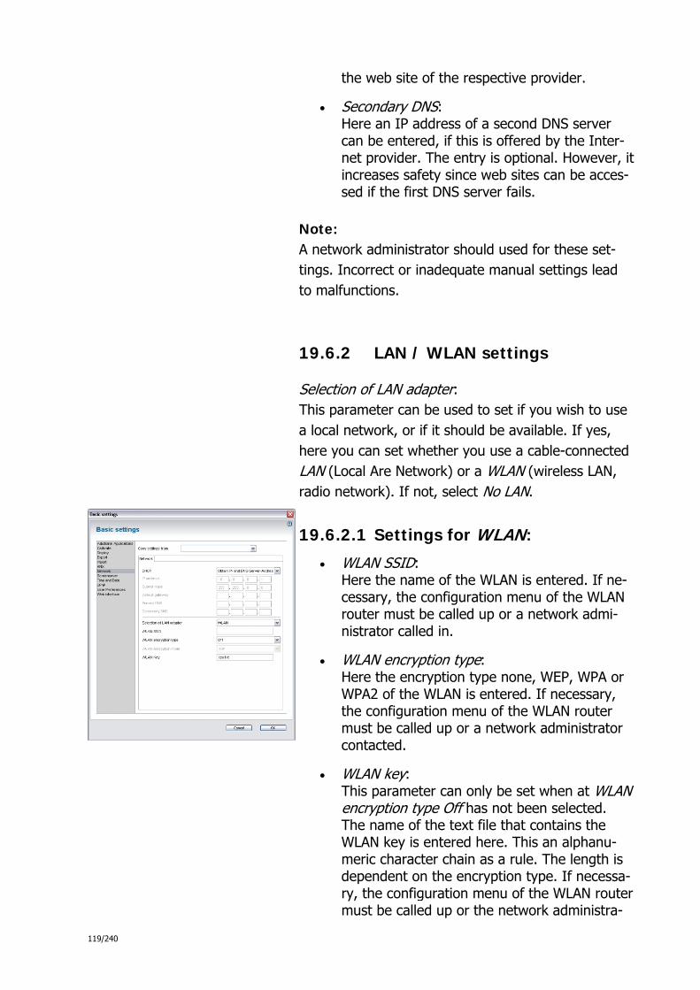
119/240
the web site of the respective provider.
Secondary DNS: Here an IP address of a second DNS server can be entered, if this is offered by the Inter-net provider. The entry is optional. However, it increases safety since web sites can be acces-sed if the first DNS server fails.
Note: A network administrator should used for these set-tings. Incorrect or inadequate manual settings lead to malfunctions.
19.6.2 LAN / WLAN settings
Selection of LAN adapter: This parameter can be used to set if you wish to use a local network, or if it should be available. If yes, here you can set whether you use a cable-connected LAN (Local Are Network) or a WLAN (wireless LAN, radio network). If not, select No LAN.
19.6.2.1 Settings for WLAN:
WLAN SSID: Here the name of the WLAN is entered. If ne-cessary, the configuration menu of the WLAN router must be called up or a network admi-nistrator called in.
WLAN encryption type: Here the encryption type none, WEP, WPA or WPA2 of the WLAN is entered. If necessary, the configuration menu of the WLAN router must be called up or a network administrator contacted.
WLAN key: This parameter can only be set when at WLAN encryption type Off has not been selected. The name of the text file that contains the WLAN key is entered here. This an alphanu-meric character chain as a rule. The length is dependent on the encryption type. If necessa-ry, the configuration menu of the WLAN router must be called up or the network administra-
120/240
tor contacted.
Note: A WLAN should always be encrypted for security reasons. Otherwise there is the risk of someone gaining access to the network from the outside to cause damage. At present the WPA2 encryption offers the highest protection pos-sible.
Note: The file with the name that you have selected in the WLAN key field -- in most cases "key.txt", will have to be impor-ted later into the WLAN network settings of the Comfort Panel in order for the WLAN key to become effective.
Example: Using a text editor, create a file with the name that you have selected in the field WLAN key -- in most cases "key.txt".
In the case of WPA/WPA2, the file must contain the WLAN key as plain text. Example: "Secret"
There are two options for WEP, with regards to the contents of the file key.txt:
Here, the WLAN key can ether be saved in plain text, however, in this case "S:" must be prepended. Example: "S:Secret"
Alternatively, the WLAN key can be entered as hexadecimal number: Example: "536563726574" or "47656865696D6E6973"

121/240
19.7 → Activating UPnP
Parameter Activate UPnP service in dialogue Basic set-tings under UPnP is used to to activate Universal Plug and Play (UPnP).
The Comfort Panel depends on UPnP to open a UPnP port and register itself in the UPnP network. This ability is re-quired for sending and receiving a project from IPP via a network.
19.8 → Activating additional applications
19.8.1 Activating simulated presence
Simulated presence can be used to record processes in the house (e.g. switching of lights, adjusting blinds) while the user is present (recording mode) and then carry them out (playback mode) during the user's absence.
Simulated presence does not have a visual control page on the Comfort Panel but can only be accessed by the user via the status bar. It is therefore activated via dialogue Basic settings. This setting is located in view Additional applica-tions in field Simulated presence. Simulated presence is active when Yes is selected.
After activating, you can configure this application in an editor (see Configuring additional applications).
Note: The default setting for simulated presence is active.
19.9 → Configuring additional applications
19.9.1 Configuring simulated presence
If simulated presence has been activated, the user has the option of editing this function directly on the Comfort Pa-nel. It would be practical to pre-configure simulated pre-sence in the IP project. The respective editor can be called up in the parameter section of the Comfort Panel via the

122/240
button Simulated presence or via the menu under Comfort Panel > Optional software modules > Simulated presence.
Note: The editor for simulated presence can be called up only when this software module has been previously activated (see Activating simulated presence).
In the editor the recording channels can be configured and equipped with group addresses. This defines the processes the Comfort Panel is to record during presence and play back during absence. The editor consists of the following sectors:
In the Library sector the group addresses are handled the same as in the IP main pro-ject window; however, they cannot be edited here.
The Work area contains the data points of the presence simulation (enable + channels).
The Parameter sector does no react in the context of the marked elements in the work sector of the editor. It contains additional pa-rameters.
In the work sector the simulated presence can be started and ended via the Bus with the 1-bit communication object Enable. An IN telegram activates the simulated presence, an OUT telegram deactivates it again.
With communication objects Simulation 1 to Simulation 20 a group address or action can be linked which records a 1-bit value or 1-byte value for the simulated presence. In addition, the Comfort Panel records the telegram interval times. After activating the simulation the stored data are transmitted according to the recorded intervals.
The group addresses from the library sector can be alloca-ted to the data points via drag and drop.
Note: To correctly allocate the group addresses to the data points you can have additional information displayed about each data point (e.g. data point type). A tool tip appears when you pull the mouse pointer across the data point.
19.9.1.1 Further settings in the parameter sector
Waiting time up to activation: Parameter Waiting time up to activation in the parameter sector of the editor is used to set
123/240
the number of channels to be monitored for the simulated presence. Up to 20 channels are possible. The Comfort Panel makes one 1-bit and one 1-byte communication object avai-lable for each channel. This enables group addresses or actions to be received (recorded) and subsequently transmitted again
Simulated presence: This parameter is used to activate or deactiva-te the presence function.
Select time lapse mode:
The time lapse mode can be selected for test purposes. Here the recorded telegrams are played without time intervals.
19.9.2 Function of the simulated presence
Recording mode: The simulated presence records the telegrams of 20 objects over the period of one week and stores these with week-day, time, object number and value (1 bit/1 byte). If more than one telegram arrives per object and minute, only the last telegram is tested and stored. Only the change of state is recorded, i.e. with telegrams of the same content only the first one is recorded.
Up to 20 actions per day and object are recorded. If there are more telegrams within a 24-hour period, the oldest telegram is deleted from the memory. The simulated pre-sence operates with one memory per object for the current day and the respective weekdays.
In recording mode the current events of the day are written in the memory. Under no circumstances is the existing day (today a week ago) immediately deleted. During the chan-geover to the following weekday the current day in place of the day a week ago is stored.
Playback mode: In the playback mode the values stored after starting time (a week ago today) are transmitted to the Bus precisely to the minute. These are transferred parallel to the relevant current day and, together with the values that have been recorded up to now, form the basis for saving at the chan-geover of the day.
If during playback no values have been recorded for a day in the first week of recording, the simulated absence sear-ches a stored period and starts the playback. This makes

124/240
values for playback available also after the recording peri-od of one day.
If the playback mode is exited, the function returns to the recording mode and continues to fill the memory of the current day.
19.9.3 Activating access control
Access control does not have a visible application page on the Comfort Panel. It is therefore activated via dialogue Basic settings. This setting is located in view Additional applications in field Access control. Access control is acti-ve when Yes is selected.
Note: The default setting for access control is active.
19.9.4 Configuring access control
Certain areas of the Comfort Panel can be equipped with access protection. This is displayed on the Comfort Panel by means of a small lock icon next to the respective head-line of the page or the operating element. When actuating the button the user must first enter a four-digit code to trigger the function.
Different user levels can be created for the access control with the editor and the relevant four-digit security number (PIN) can be set. You can also assign a user level to indi-vidual pages and control elements in the Comfort panel. The pages and control elements can then only be operated with the respective user level.
Note: As alternative to the central assignment of access rights to the individual pages and functions (via the editor for ac-cess control) you can also make these settings directly on the elements. If, for example, you wish to assign access protection to an operating element, you can do this by means of parameter User level in the settings dialogue Extended settings in the parameter sector of the respective operating element.
19.9.5 Activating the camera module
The Comfort Panel can be expanded with a camera module offering the user additional areas of application. This al-lows the Intercom, Video monitoring and Baby phone ap-plications to be used with a video image.

125/240
The camera module is activated via Basic settings dialog. This setting is located in theAdditional applications view in Camera module field. The camera module is activated when Yes is selected there.
You can use the internal camera in the corresponding ap-plications if the key module is present on the device and the software module with the same name is activated. Ad-ditional settings are not required.
Note: The default setting for access control is deactivated.
19.9.6 Activating the baby phone receiver
Using the Baby phone application, cameras and micropho-nes of other Comfort Panels in the network can be used, for example, to monitor a sleeping baby in a children's room. If the sound levels there exceed a set value, the Ba-by phone application establishes an audio/video connection to other selected panels. A panel must be configured as Baby phone receiver so that it can receive the audio/video data of a Baby phone monitor.
To do this, the additional Baby phone receiver application must be activated in the Basic settings dialog. This setting is located in Additional applications view in the Baby phone field. Select Yes there.
After activating, you can configure the Baby phone recei-ver (see Configuring a baby phone application page).
Note: The Baby phone receiver is deactivated in the default set-ting.
19.9.7 Activating logic functions
Complex switching sequences can be realised in the Com-fort Panel using so-called Logic functions. However, these can only be created in IP Project if the corresponding software module has been activated first.
The logic functions are activated via Basic settings dialog. This setting is located in view Additional applications in the Logic editor field. Logic functions are activated when Yes is selected.
After activating, you can configure the logic functions in an editor (see here).
Note:
126/240
Logic functions are deactivated by default.
After activation you can configure following parameters in theBasic Settings dialog:
The parameter Queue size defines the size of the input buf-fer of the logic engine.
The parameterOverflow behavior defines how to proceed if the input buffer is flooded.
Skip new events defines that newly received elements are to be ignored.
Remove old elements defines that on retrieval of new elements old elements are to be remo-ved from the input queue. In this case the pa-rameter Elements to remove defines how ma-ny of the oldest elements are to be discarded.
The parameter Sending delay defines the time in mil-liseconds the logic engine waits after calculating new values, until these values are sent.
Please note: Very low sending delay values may lead to a significantly increased CPU load.
19.9.8 Activating Remote Desktop
The Comfort Panel can be controlled remotely via the VNC protocol (Virtual Network Computing). To do this, you simply need to enter the IP address of the Comfort Panel in a browser on a PC in the network. You then get the complete user interface as it is seen on the display of the Comfort Panel.
It is thus possible to trigger all operating functions remote-ly and see all information that the Comfort Panel displays from a different location. The call-up is also possible through the Internet via VPN, provided that the panel is connected to a router that has Internet access.
The Remote Desktop does not have a visible application page on the Comfort Panel. It is therefore activated via dialogue Basic settings. You can find this setting in the Additional applications view in the Remote Desktop field. The Remote Desktop is active when Yes is selected.
After activating, you can configure this application in an editor (see Configuring additional applications).
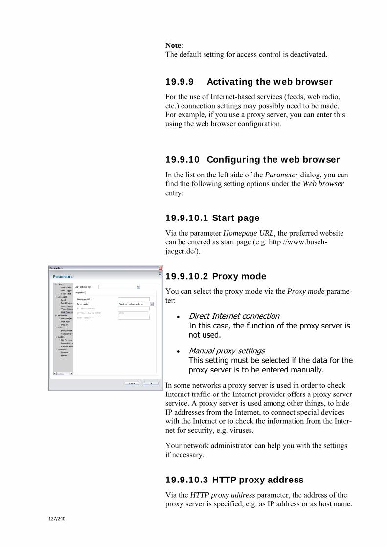
127/240
Note: The default setting for access control is deactivated.
19.9.9 Activating the web browser
For the use of Internet-based services (feeds, web radio, etc.) connection settings may possibly need to be made. For example, if you use a proxy server, you can enter this using the web browser configuration.
19.9.10 Configuring the web browser
In the list on the left side of the Parameter dialog, you can find the following setting options under the Web browser entry:
19.9.10.1 Start page
Via the parameter Homepage URL, the preferred website can be entered as start page (e.g. http://www.busch-jaeger.de/).
19.9.10.2 Proxy mode
You can select the proxy mode via the Proxy mode parame-ter:
Direct Internet connection In this case, the function of the proxy server is not used.
Manual proxy settings This setting must be selected if the data for the proxy server is to be entered manually.
In some networks a proxy server is used in order to check Internet traffic or the Internet provider offers a proxy server service. A proxy server is used among other things, to hide IP addresses from the Internet, to connect special devices with the Internet or to check the information from the Inter-net for security, e.g. viruses.
Your network administrator can help you with the settings if necessary.
19.9.10.3 HTTP proxy address
Via the HTTP proxy address parameter, the address of the proxy server is specified, e.g. as IP address or as host name.

128/240
You can get this from your network administrator.
This parameter can only be set if the proxy mode was set toManual proxy settings.
19.9.10.4 HTTP proxy port
The required port is specified via the HTTP proxy port pa-rameter. In many cases, this is preset to port "8080". You can get the information about the required port from your network administrator.
This parameter can only be set if the proxy mode was set toManual proxy settings.
19.9.10.5 HTTP proxy exceptions
You can create an exception list that is used by some Inter-net servers that do not support proxy server functions via the No HTTP proxy for parameter.
This parameter can only be set if the proxy mode was set to Manual proxy settings.
Supported delimiters are semicolon, comma and „|“. Furthermore, you can use "*" as placeholder. Any blanks within the list are ignored. Example: 205.105.148.*;www.msn.*,212.145.33.22|www.google.com
19.9.11 Using the simulated presence
Simulated presence can be used to record processes in the house (e.g. switching of lights, adjusting blinds) while the user is present (recording mode) and then carry them out (playback mode) during the user's absence.
Recording mode: The simulated presence records the telegrams of 20 objects over the period of one week and stores these with week-day, time, object number and value (1 bit/1 byte). If more than one telegram arrives per object and minute, only the last telegram is tested and stored. Only the change of state is recorded, i.e. with telegrams of the same content only the first one is recorded.
Up to 20 actions per day and object are recorded. If there are more telegrams within a 24-hour period, the oldest telegram is deleted from the memory. The simulated pre-sence operates with one memory per object for the current day and the respective weekdays.

129/240
In recording mode the current events of the day are written in the memory. Under no circumstances is the existing day (today a week ago) immediately deleted. During the chan-geover to the following weekday the current day in place of the day a week ago is stored.
Playback mode: In the playback mode the values stored after starting time (a week ago today) are transmitted to the Bus precisely to the minute. These are transferred parallel to the relevant current day and, together with the values that have been recorded up to now, form the basis for saving at the chan-geover of the day.
If during playback no values have been recorded for a day in the first week of recording, the simulated absence sear-ches a stored period and starts the playback. This makes values for playback available also after the recording peri-od of one day.
If the playback mode is exited, the function returns to the recording mode and continues to fill the memory of the current day.
19.9.12 Setting the simulated presence
If simulated presence has been activated, the user has the option of editing this function directly on the Comfort Pa-nel. It would be practical to pre-configure simulated pre-sence in the IP project. The respective editor can be called up in the parameter section of the Comfort Panel via the button Simulated presence or via the menu under Comfort Panel > Optional software modules > Simulated presence.
Note: The editor for simulated presence can only be called up if this software module has been previously activated (see Activating additional applications).
19.9.12.1 Configuring recording channels
In the editor the recording channels can be configured and equipped with group addresses. This defines the processes the Comfort Panel is to record during presence and play back during absence. The editor consists of the following sectors:
In the Library sector the group addresses are handled the same as in the IP main pro-ject window; however, they cannot be edited

130/240
here.
The Work area contains the data points of the presence simulation (enable + channels).
The Parameter sector does no react in the context of the marked elements in the work sector of the editor. It contains additional pa-rameters.
In the work sector the simulated presence can be started and ended via the Bus with the 1-bit communication object Enable. An IN telegram activates the simulated presence, an OUT telegram deactivates it again.
With communication objects Simulation 1 to Simulation 20 a group address or action can be linked which records a 1-bit value or 1-byte value for the simulated presence. In addition, the Comfort Panel records the telegram interval times. After activating the simulation the stored data are transmitted according to the recorded intervals.
The group addresses from the library sector can be alloca-ted to the data points via drag and drop.
Note: To correctly allocate the group addresses to the data points you can have additional information displayed about each data point (e.g. data point type). A tool tip appears when you pull the mouse pointer across the data point.
19.9.12.2 Further settings in the parameter sector
Waiting time up to activation: Parameter Waiting time up to activation in the parameter sector of the editor is used to set the number of channels to be monitored for the simulated presence. Up to 20 channels are possible. The Comfort Panel makes one 1-bit and one 1-byte communication object avai-lable for each channel. This enables group addresses or actions to be received (recorded) and subsequently transmitted again
Simulated presence: This parameter is used to activate or deactiva-te the presence function.
Select time lapse mode: The time lapse mode can be selected for testing purposes. Here the recorded telegrams
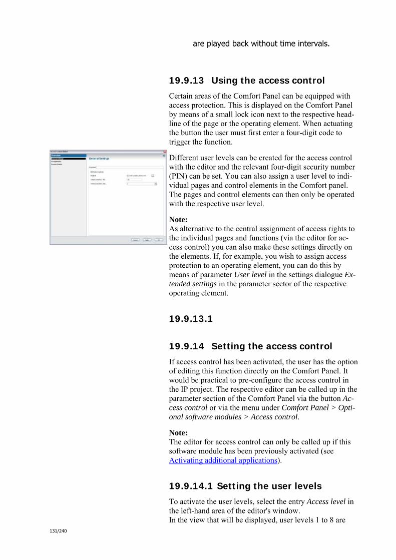
131/240
are played back without time intervals.
19.9.13 Using the access control
Certain areas of the Comfort Panel can be equipped with access protection. This is displayed on the Comfort Panel by means of a small lock icon next to the respective head-line of the page or the operating element. When actuating the button the user must first enter a four-digit code to trigger the function.
Different user levels can be created for the access control with the editor and the relevant four-digit security number (PIN) can be set. You can also assign a user level to indi-vidual pages and control elements in the Comfort panel. The pages and control elements can then only be operated with the respective user level.
Note: As alternative to the central assignment of access rights to the individual pages and functions (via the editor for ac-cess control) you can also make these settings directly on the elements. If, for example, you wish to assign access protection to an operating element, you can do this by means of parameter User level in the settings dialogue Ex-tended settings in the parameter sector of the respective operating element.
19.9.13.1
19.9.14 Setting the access control
If access control has been activated, the user has the option of editing this function directly on the Comfort Panel. It would be practical to pre-configure the access control in the IP project. The respective editor can be called up in the parameter section of the Comfort Panel via the button Ac-cess control or via the menu under Comfort Panel > Opti-onal software modules > Access control.
Note: The editor for access control can only be called up if this software module has been previously activated (see Activating additional applications).
19.9.14.1 Setting the user levels
To activate the user levels, select the entry Access level in the left-hand area of the editor's window. In the view that will be displayed, user levels 1 to 8 are

132/240
listed in which you can activate each level individually via the checkbox. Stage 0 (guest) is permanently activated.
For user levels that are activated the PIN, which is 0000 as standard, should be changed.
19.9.14.2 Assigning pages and operating elements to the user levels
With the user levels so defined, you can then configure the access control for single pages and operating elements. Then select the entry Assignments in the left window sec-tion of the editor. In this view all pages and operating ele-ments are listed that have been created up to now in the Comfort panel. Also displayed is the user level assigned to each element. Standard is level 0, which does not require a PIN. You now have the opportunity to edit the assignment of the access levels.
In view Default settings and via the checkbox Activate blips you can set whether a blip is to be played. This signal sounds as soon as access is denied by the access control.
19.9.14.3 Time interval for a return to user level 0
You can define a time interval for a return to user level 0. The authorization status of a user on the Comfort Panel is limited timewise. After a correct entry of a PIN an internal timer starts. When the timer has run down, the user's cur-rent authorization level is withdrawn and he is again log-ged in as guest. The timer starts anew each time the user makes an entry on the screen. The length of the time inter-val can be configured in view Default settings via Automa-tic block.
19.9.15 Using logic functions
Please look here.

133/240
19.9.16 Using the Remote Desktop
The Comfort Panel can be controlled remotely via the VNC protocol (Virtual Network Computing). To do this, you simply need to enter the IP address of the Comfort Panel in a browser on a PC in the network. You then get the complete user interface as it is seen on the display of the Comfort Panel.
It is thus possible to trigger all operating functions remote-ly and see all information that the Comfort Panel displays from a different location. The call-up is also possible through the Internet via VPN, provided that the panel is connected to a router that has Internet access.
19.9.17 Setting Remote Desktop
If Remote Desktop was activated, you can make settings in the Application settings dialog. The dialog can be reached via the parameter section of the respective Comfort Panel using the button Application settings or via the menu under Panel > Application settings. Select Remote Desktop in the left area there.
Note: The dialog for Application settings can only then be called up if the software module Remote Desktop has been pre-viously activated (see Activating additional applications).
19.9.17.1 Specifying user name and password
You specify the user name and password that are required for the access via Remote Desktop via the parameters User name for remote access and Password for remote access.
19.9.17.2 Setting the time interval for automatic logging off
The Timeout due to inactivity parameter specifies the time after which Remote Destop will be ended automatically. Any time interval can be defined here from 1 second to 1440 seconds. It is possible to deactivate this automatic logout function with No timeout. For security reasons, the Remote Desktop should, however, be ended automatically.

134/240
19.10 → Configuring the acoustic signals of the Comfort Panel
19.10.1 Configuring the welcome signal
A welcoming signal can be played at the start of the Com-fort Panel. To do this go to User preferences and in tab Basis activate checkbox Activate welcome signal.
If you wish to change the welcome signal, select a diffe-rent one under Welcome signal.
19.10.2 Configuring button signal
When actuating a button an acoustic signal can be played by the Comfort Panel.
Any kind of signal tone can be set in the list Activate acoustic signal for buttons under User preferences in tab Basis. This function can be deactivated with No.
19.11 → Setting separators
19.11.1 Setting decimal separators
Under User preferences in tab Basis and by means of pa-rameter Decimal separators you can set whether a comma (German separator) or a point (English separator) is to be used as decimal separator.
19.11.2 Setting the thousands separator
Under User preferences in tab Basis and by means of pa-rameter Thousands separators you can set whether thou-sands are to separated with a comma (English separator) or a point (German separator).

135/240
19.12 → Configuring the temperature display in the status bar of the Comfort Panel
19.12.1 Setting the temperature format
The Comfort Panel has a temperature display in the status bar. Via parameter Temperature unit under User preferen-ces in tab Temperature you can select between temperature units Celsius or Fahrenheit.
19.12.2 Selecting temperature sensor
Under User preferences in tab Basis and by means of pa-rameter Room temperature sensor you can set whether the indoor temperature is to be handled via the internal sensor of the Comfort Panel or via the external KNX temperature sensor.
19.12.3 Activating the temperature display
Parameters Display room temperature and Display outdoor temperature are used to set whether the indoor or outdoor temperature is to be displayed in the status bar.
Indoor or outdoor temperature share a space in the status line and are shown alternatingly (pro-vided this is configured)!
19.13 → Configuring automatic maintenance
19.13.1 Selecting the maintenance cycle
Parameter Maintenance mode under User preferences in tab Maintenance is used to set whether the Comfort Panel is to be cyclically re-started for maintenance purposes. This can be of assistance when a malfunction occurs inside the Comfort Panel. This makes a manual restart unnecessa-ry.
If cyclic restarts are to be carried out, they can be set daily, weekly or monthly.
Note: Mail and alarm functions are not affected by the mainte-

136/240
nance function.
19.13.2 Setting the time for maintenance
19.13.2.1 Day
If maintenance is to be carried out, the day of the week or the month this is to take place is set via parameters Weekly maintenance period and Monthly maintenance period.
19.13.2.2 Time
If maintenance is to be carried out, the period over which this is to take place is set via parame-ters Start of maintenance period and End of maintenance period. Practical is a time interval during which the Comfort Panel is unlikely to be used (e.g. from 1 a.m. to 5 a.m.).
19.14 → Configuring access to the web interface
19.14.1 Defining user names
Via parameter User name under Web interface you can define a user name with which a user can log himself into the Web interface of the Comfort Panel.
Via parameter Master user name you can also define an administrator name with which a user can log himself into the Web interface of the Comfort Panel.
19.14.2 Setting passwords
Via parameters Password and Password under Web inter-face you can define passwords with which users and admi-nistrators can log themselves into the Web interface of the Comfort Panel. You need to enter each password a second time under Confirm password.
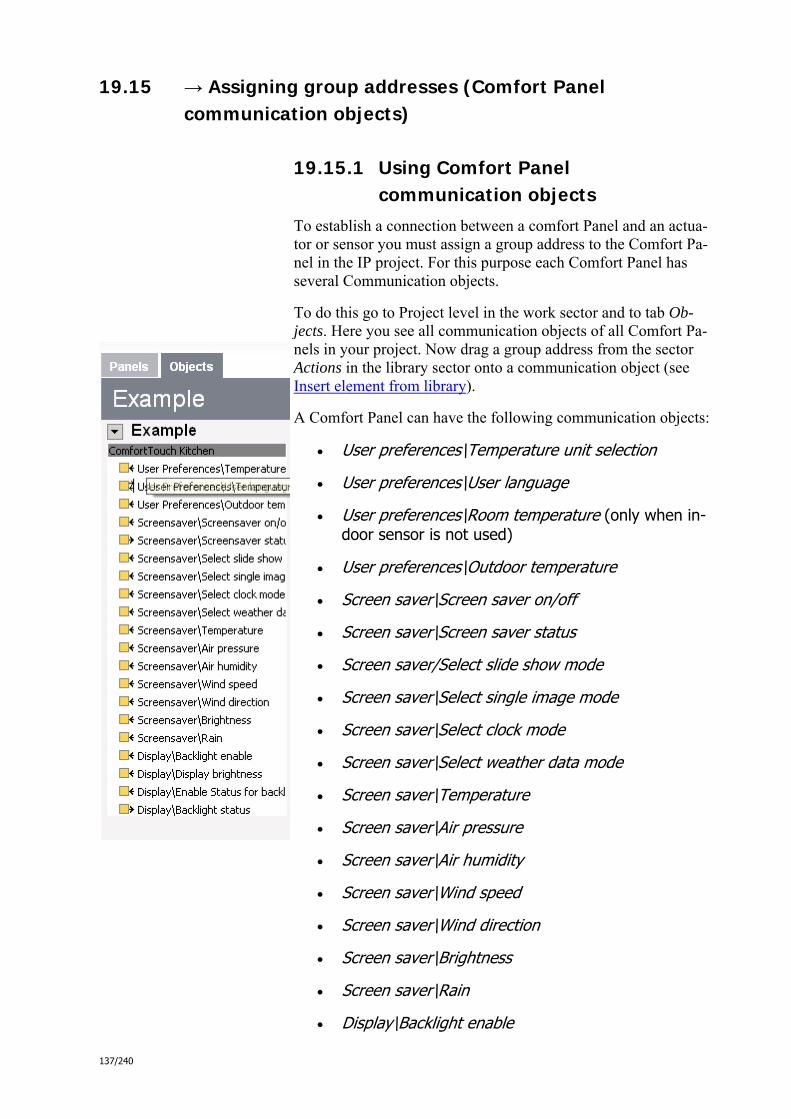
137/240
19.15 → Assigning group addresses (Comfort Panel communication objects)
19.15.1 Using Comfort Panel communication objects
To establish a connection between a comfort Panel and an actua-tor or sensor you must assign a group address to the Comfort Pa-nel in the IP project. For this purpose each Comfort Panel has several Communication objects.
To do this go to Project level in the work sector and to tab Ob-jects. Here you see all communication objects of all Comfort Pa-nels in your project. Now drag a group address from the sector Actions in the library sector onto a communication object (see Insert element from library).
A Comfort Panel can have the following communication objects:
User preferences\Temperature unit selection
User preferences\User language
User preferences\Room temperature (only when in-door sensor is not used)
User preferences\Outdoor temperature
Screen saver\Screen saver on/off
Screen saver\Screen saver status
Screen saver/Select slide show mode
Screen saver\Select single image mode
Screen saver\Select clock mode
Screen saver\Select weather data mode
Screen saver\Temperature
Screen saver\Air pressure
Screen saver\Air humidity
Screen saver\Wind speed
Screen saver\Wind direction
Screen saver\Brightness
Screen saver\Rain
Display\Backlight enable

138/240
Display\Display brightness
Display\Enable status for backlight
Display\Backlight status
19.15.2 User preferences\Temperature unit selection
This 1-bit communication object can be used to switch the unit for temperature between Celsius and Fahrenheit. A switch-off telegram activates the unit °C and a switch-on telegram the unit F.
19.15.3 User preferences\User language
This 1-byte communication object is used to change the User lan-guage via the Bus.
19.15.4 User preferences\Room temperature
This communication object is available only when the indoor temperature sensor of the Comfort Panel is not to be used and parameter Room temperature sensor has been set on External (see Configuring the temperature display in the status bar of the Com-fort Panel).
Via this 2-byte communication object the indoor temperature is received from an outdoor temperature sensor.
19.15.5 User preferences\Outdoor temperature
Via this 2-byte communication object the temperature is received from an outdoor temperature sensor.
19.15.6 Screen saver\Screen saver on/off This 1-bit communication object is used to switch the scree saver off and on externally. The receipt of a switch-on telegram activa-tes the screen saver and a switch-off telegram deactivates it.
Note: The time set under parameter Display screen saver only expires after the receipt of a switch-on telegram.
19.15.7 Screen saver\Screen saver status

139/240
When the screen saver is activated the 1-bit communication ob-ject sends a telegram with value 1. When the screen saver ends, the 1-bit communication object sends a telegram with value 0.
19.15.8 Screen saver\Select slide show mode Screen saver\Select single image mode Screen saver\Select clock mode Screen saver\Select weather data mode
The respective mode can be activated or deactivated as screen saver via these 1-bit communication objects. A switch-on tele-gram activates the mode, a switch-off telegram deactivates it.
Note: The four 1-bit communication objects for activating the various screen savers have different priorities. The object Screen sa-ver\Select slide show mode has the highest priority, then follow the objects Screen saver\select single image mode, Screen sa-ver\Select clock mode and Screen saver\Select weather data mode. If two or more objects simultaneously have value 1, the object with the highest priority will assert itself.
19.15.9 Screen saver\Temperature
Via this 2-byte communication object telegrams with temperature values can be received and evaluated, e.g. the ones transmitted by a KNX weather station. The 2-byte floating point values are eva-luated according to EIS5.
19.15.10 Screen saver\Air pressure
Telegrams with air pressure values can be can be received and evaluated via this 2-byte communication object, e.g. the ones transmitted by a KNX weather station. The 2-byte floating point values are evaluated according to EIS5.
19.15.11 Screen saver\Air humidity
Via this 1-byte communication object telegrams with air humidity values can be received and evaluated, e.g. the ones transmitted by a KNX weather station.
The value 0 means 0% air humidity and the value 255 means 100% air humidity.

140/240
19.15.12 Screen saver\Wind speed
Via this 2-byte communication object telegrams with wind speed values can be received and evaluated, e.g. the ones transmitted by a KNX weather station. The 2-byte floating point values are eva-luated according to EIS5.
19.15.13 Screen saver\Wind direction
Via this 1-byte communication object telegrams with wind direc-tion values can be received and evaluated, e.g. the ones transmit-ted by a KNX weather station.
The value 0 means 0° and the value 255 means 360°.
19.15.14 Screen saver\Brightness
Telegrams with brightness values can be can be received and eva-luated via this 2-byte communication object, e.g. the ones trans-mitted by a KNX weather station. The 2-byte floating point va-lues are evaluated according to EIS5.
19.15.15 Screen saver\Rain
Via this 1-bit communication object information about rainfall can be received and evaluated, e.g. the ones transmitted by a KNX weather station. A telegram with value 0 is interpreted as No rain and the receipt of a telegram with value 1 is interpreted as Rain.
19.15.16 Screen saver\Backlight enable
This 1-bit communication object is used to switch the display backlight on and off. The receipt of a switch-on telegram activa-tes the display backlight, the receipt of a switch-off telegram deactivates it.
19.15.17 Screen saver\Display brightness
The brightness of the display can be set via this 1-byte communi-cation object. Value 0 means 0% and value255 means 100% display brightness.
19.15.18 Screen saver\Enable status for backlight
This 1-bit communication object activates or deactivates the Screen saver\Backlight status communication object. If a switch-

141/240
on telegram is received on Enable status for backlight, the object Screen saver\Backlight status is active. If a switch-off telegram is received on Enable status for backlight, the object Backlight sta-tus is not active.
19.15.19 Screen saver\Backlight status
This 1-bit communication object is used to signal whether the display backlight is switched on or off. When the display backlight is switched on, a telegram with value 1 is sent, and a telegram with value 0 is sent when it is switched off.
Note: The communication object can be activated or deactivated via the 1-bit communication object Screen saver\Enable status for backlight.
20 Configuring additional applications (Comfort Panel)
Comfort Panel applications whose configuration is more complex have a special editor window in IP Project. You can access these via the respective buttons in the parameter area and via Comfort Panel > Default settings in the menu:
when the required Comfort Panel is marked in the Project level or
when no other element is marked on the Navigation level.
20.1 → Configuring the simulated presence
20.1.1 Using the simulated presence
Simulated presence can be used to record processes in the house (e.g. switching of lights, adjusting blinds) while the user is present (recording mode) and then carry them out (playback mode) during the user's absence.
Recording mode: The simulated presence records the telegrams of 20 objects over the period of one week and stores these with week-day, time, object number and value (1 bit/1 byte). If more than one telegram arrives per object and minute, only the last telegram is tested and stored. Only the change of state is recorded, i.e. with telegrams of the same content only the first one is recorded.
Up to 20 actions per day and object are recorded. If there are more telegrams within a 24-hour period, the oldest
142/240
telegram is deleted from the memory. The simulated pre-sence operates with one memory per object for the current day and the respective weekdays.
In recording mode the current events of the day are written in the memory. Under no circumstances is the existing day (today a week ago) immediately deleted. During the chan-geover to the following weekday the current day in place of the day a week ago is stored.
Playback mode: In the playback mode the values stored after starting time (a week ago today) are transmitted to the Bus precisely to the minute. These are transferred parallel to the relevant current day and, together with the values that have been recorded up to now, form the basis for saving at the chan-geover of the day.
If during playback no values have been recorded for a day in the first week of recording, the simulated absence sear-ches a stored period and starts the playback. This makes values for playback available also after the recording peri-od of one day.
If the playback mode is exited, the function returns to the recording mode and continues to fill the memory of the current day.
20.1.2 Setting the simulated presence
If simulated presence has been activated, the user has the option of editing this function directly on the Comfort Pa-nel. It would be practical to pre-configure simulated pre-sence in the IP project. The respective editor can be called up in the parameter section of the Comfort Panel via the button Simulated presence or via the menu under Comfort Panel > Optional software modules > Simulated presence.
Note: The editor for simulated presence can only be called up if this software module has been previously activated (see Activating additional applications).
20.1.2.1 Configuring recording channels
In the editor the recording channels can be configured and equipped with group addresses. This defines the processes the Comfort Panel is to record during presence and play back during absence. The editor consists of the following sectors:
In the Library sector the group addresses are handled the same as in the IP main pro-

143/240
ject window; however, they cannot be edited here.
The Work area contains the data points of the presence simulation (enable + channels).
The Parameter sector does no react in the context of the marked elements in the work sector of the editor. It contains additional pa-rameters.
In the work sector the simulated presence can be started and ended via the Bus with the 1-bit communication object Enable. An IN telegram activates the simulated presence, an OUT telegram deactivates it again.
With communication objects Simulation 1 to Simulation 20 a group address or action can be linked which records a 1-bit value or 1-byte value for the simulated presence. In addition, the Comfort Panel records the telegram interval times. After activating the simulation the stored data are transmitted according to the recorded intervals.
The group addresses from the library sector can be alloca-ted to the data points via drag and drop.
Note: To correctly allocate the group addresses to the data points you can have additional information displayed about each data point (e.g. data point type). A tool tip appears when you pull the mouse pointer across the data point.
20.1.2.2 Further settings in the parameter sector
Waiting time up to activation: Parameter Waiting time up to activation in the parameter sector of the editor is used to set the number of channels to be monitored for the simulated presence. Up to 20 channels are possible. The Comfort Panel makes one 1-bit and one 1-byte communication object avai-lable for each channel. This enables group addresses or actions to be received (recorded) and subsequently transmitted again
Simulated presence: This parameter is used to activate or deactiva-te the presence function.
Select time lapse mode: The time lapse mode can be selected for testing purposes. Here the recorded telegrams
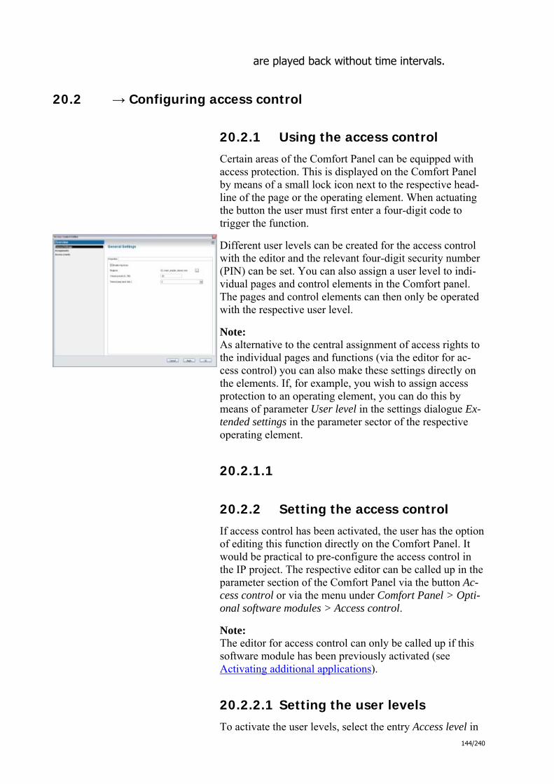
144/240
are played back without time intervals.
20.2 → Configuring access control
20.2.1 Using the access control
Certain areas of the Comfort Panel can be equipped with access protection. This is displayed on the Comfort Panel by means of a small lock icon next to the respective head-line of the page or the operating element. When actuating the button the user must first enter a four-digit code to trigger the function.
Different user levels can be created for the access control with the editor and the relevant four-digit security number (PIN) can be set. You can also assign a user level to indi-vidual pages and control elements in the Comfort panel. The pages and control elements can then only be operated with the respective user level.
Note: As alternative to the central assignment of access rights to the individual pages and functions (via the editor for ac-cess control) you can also make these settings directly on the elements. If, for example, you wish to assign access protection to an operating element, you can do this by means of parameter User level in the settings dialogue Ex-tended settings in the parameter sector of the respective operating element.
20.2.1.1
20.2.2 Setting the access control
If access control has been activated, the user has the option of editing this function directly on the Comfort Panel. It would be practical to pre-configure the access control in the IP project. The respective editor can be called up in the parameter section of the Comfort Panel via the button Ac-cess control or via the menu under Comfort Panel > Opti-onal software modules > Access control.
Note: The editor for access control can only be called up if this software module has been previously activated (see Activating additional applications).
20.2.2.1 Setting the user levels
To activate the user levels, select the entry Access level in

145/240
the left-hand area of the editor's window. In the view that will be displayed, user levels 1 to 8 are listed in which you can activate each level individually via the checkbox. Stage 0 (guest) is permanently activated.
For user levels that are activated the PIN, which is 0000 as standard, should be changed.
20.2.2.2 Assigning pages and operating elements to the user levels
With the user levels so defined, you can then configure the access control for single pages and operating elements. Then select the entry Assignments in the left window sec-tion of the editor. In this view all pages and operating ele-ments are listed that have been created up to now in the Comfort panel. Also displayed is the user level assigned to each element. Standard is level 0, which does not require a PIN. You now have the opportunity to edit the assignment of the access levels.
In view Default settings and via the checkbox Activate blips you can set whether a blip is to be played. This signal sounds as soon as access is denied by the access control.
20.2.2.3 Time interval for a return to user level 0
You can define a time interval for a return to user level 0. The authorization status of a user on the Comfort Panel is limited timewise. After a correct entry of a PIN an internal timer starts. When the timer has run down, the user's cur-rent authorization level is withdrawn and he is again log-ged in as guest. The timer starts anew each time the user makes an entry on the screen. The length of the time inter-val can be configured in view Default settings via Automa-tic block.

146/240
20.3 → Configuring Remote Desktop
20.3.1 Using the Remote Desktop
The Comfort Panel can be controlled remotely via the VNC protocol (Virtual Network Computing). To do this, you simply need to enter the IP address of the Comfort Panel in a browser on a PC in the network. You then get the complete user interface as it is seen on the display of the Comfort Panel.
It is thus possible to trigger all operating functions remote-ly and see all information that the Comfort Panel displays from a different location. The call-up is also possible through the Internet via VPN, provided that the panel is connected to a router that has Internet access.
20.3.2 Setting Remote Desktop
If Remote Desktop was activated, you can make settings in the Application settings dialog. The dialog can be reached via the parameter section of the respective Comfort Panel using the button Application settings or via the menu under Panel > Application settings. Select Remote Desktop in the left area there.
Note: The dialog for Application settings can only then be called up if the software module Remote Desktop has been pre-viously activated (see Activating additional applications).
20.3.2.1 Specifying user name and password
You specify the user name and password that are required for the access via Remote Desktop via the parameters User name for remote access and Password for remote access.
20.3.2.2 Setting the time interval for automatic logging off
The Timeout due to inactivity parameter specifies the time after which Remote Destop will be ended automatically. Any time interval can be defined here from 1 second to 1440 seconds. It is possible to deactivate this automatic logout function with No timeout. For security reasons, the Remote Desktop should, however, be ended automatically.

147/240
03_03_09_00_EN.html - Logikbausteine

148/240
20.3.3 KNX input module details
20.3.3.1 Behaviour
Upon receipt of an input telegram from the KNX network via the communication object DP0, the KNX input module outputs the value of the received telegram to the logical-sided Output 0.
The data type of the incoming telegram is automatically converted to the corresponding internal data type (see conversion table below).
20.3.3.2 Linking with group addresses
Every KNX input module can be linked with one or multiple group addresses. For this purpose, it has a DP0 communication object.
In order to link the communication object with group addresses, go to the Objects tab in the worksheet. Here you will see the communication objects of all input and output modules of your logic Drag a group address from the Actions area in the library area to the communication object (see Add element from library).
Note: As data type of the incoming telegram, the data type of the first linked group address on the DP0 communication object is always adopted. If values outside of the defined data range are received on the other group addresses, the KNX input module ingnores these values.
20.3.3.3 Extended settings
You can specify the initial value to be used of the KNX input module according to the type of the linked group address (see above) via the Input value parameter.
Note: This value is only then used if a logic module linked with the KNX input module is recalcula-ted, at the KNX input module, however, a KNX telegram was still not received.
20.3.3.4 Conversion table
KNX data type Data point type Range of values Internal data type

149/240
1 bit 1.xxx Boolean
2 bit 2.xxx Number (long)
4 bit 3.xxx Number (long)
1-byte unsigned 5.001 {0..100} Number (long)
5.003 {0..360} Number (long)
5.004 {0..255} Number (long)
5.010 {0..255} Number (long)
1-byte signed 6.xxx {-128..127} Number (long)
2-byte unsigned 7.xxx {0.. 65535} Number (long)
2-byte signed 8.xxx {-32768..32767} Number (long)
2-byte float 9.xxx {-671088.64..670760.96} Number (double)
3 byte 10.xxx Time
11.xxx Date
4-byte unsigned 12.xxx {0..4294967295} Number (long)
4-byte signed 13.xxx {-2147483648..2147483647} Number (long)
4-byte float 14.xxx {-Float.MAX..Float.MAX } Number (double)
Local ASCII 231.001 String
string 16.xxx String
03_03_09_00_EN.html - Logikbausteine
03_03_09_00_EN.html - Logikbausteine

150/240
20.3.4 KNX output module details
20.3.4.1 Behaviour
Upon receipt of a value via the logic-sided input data in, the KNX output module sends a tele-gram with the incoming value via the DP0 communication object into the KNX network.
The internal data type of the KNX output module is converted into the data type of the commu-nication object. If a carryover arises, a telegram with the value 1 (1-bit) is sent out via the DP1 communication object.
20.3.4.2 Linking with group addresses
Every KNX output module can be linked with one or multiple group addresses. For this purpo-se, it has communication objects.
In order to link a communication object with group addresses, go to the Objects tab in the worksheet. Here you will see the communication objects of all input and output modules of your logic Drag a group address from the Actions area in the library area to the communication object (see Add element from library).
Note: Although the editor generally does allow multiple group addresses to be linked with a commu-nication object, in the case of the KNX output module, only the first group address is used for sending!
20.3.4.3 Extended settings
Via the Only send with change parameter, you can specify whether a KNX telegram shall only be sent if a logic-sided received value is different to the previously received value.
20.3.4.4 Conversion table
KNX data type Data point type Range of values Internal data type
1 bit 1.xxx Boolean

151/240
2 bit 2.xxx Number (long)
4 bit 3.xxx Number (long)
1-byte unsigned 5.001 {0..100} Number (long)
5.003 {0..360} Number (long)
5.004 {0..255} Number (long)
5.010 {0..255} Number (long)
1-byte signed 6.xxx {-128..127} Number (long)
2-byte unsigned 7.xxx {0.. 65535} Number (long)
2-byte signed 8.xxx {-32768..32767} Number (long)
2-byte float 9.xxx {-671088.64..670760.96} Number (double)
3 byte 10.xxx Time
11.xxx Date
4-byte unsigned 12.xxx {0..4294967295} Number (long)
4-byte signed 13.xxx {-2147483648..2147483647} Number (long)
4-byte float 14.xxx {-Float.MAX..Float.MAX } Number (double)
Local ASCII 231.001 String
string 16.xxx String
03_03_09_00_EN.html - Logikbausteine
03_03_09_00_EN.html - Logikbausteine

152/240
20.3.5 IP input module details
20.3.5.1 Behaviour
Upon receipt of TCP-based data from a network, the IP input module outputs the incoming data packet to the logic-sided Output 0as soon as the sender ends the connection. Alternatively, for existing connection, individual values can be output in dependence on user-defined data block sizes or in dependence on user-defined separators (see below).
Incoming UDP-based data packets are immediately output to the logic-sided Output 0.
The data type of the incoming data is automatically converted to the set KNX-conform data type and finally, as with theKNX input module, converted to an internal data type. If errors occur, the value 1 is output on the logic-sided Output 1 (logical "true").
20.3.5.2 Extended settings
Via the Protocol parameter, you can specify whether TCP- or UDP-based data shall be received.
Via the Port No. parameter, you can specify on which port data shall be recei-ved.
Via the Limit type parameter, you can manually specify, in the case of a TCP-based communication, the point in time of the output on Output 0:
o Select Symbol as limit type. In this way, you can specify characters in he-xadecimal notation (e.g. 0x01) Limit bytes. If these characters are recei-ved, the IP input module outputs the data of the current data block.
o Select Block as limit type. In this way, you can specify under Block size the number of characters (in bytes) that belong to a data block. If this number of characters are received, the IP input module outputs the re-ceived data as data block.
Using the Preamble block size and Postambel block size parameters, you can specify by how many bytes a received data package shall be truncated:
o For UDP at the beginning and end of every UDP data package.

153/240
o For TCP at the beginning and end of the complete TCP data stream re-ceived.
Via the KNX data type or Value format parameter, you can specify to which KNX-compliant data type the received data blocks shall be converted before they are converted to the corresponding internal data type.
03_03_09_00_EN.html - Logikbausteine
03_03_09_00_EN.html - Logikbausteine

154/240
20.3.6 IP output module details
20.3.6.1 Behaviour
Upon receipt of a value via the logic-sided input data in, the IP output module sends TCP- or UDP-based data with the incoming value to a specific IP address using a specific port.
The sent data corresponds to the selected KNX-compliant data type of the IP output module.
20.3.6.2 Extended settings
Via the Only send with change parameter, you can specify whether a date shall only be sent if a logic-sided received value is different to the previously received value.
Via the Protocol parameter, you can specify whether TCP- or UDP-based data shall be sent.
Via the Port parameter, you can specify on which port data shall be sent.
Via the IP address parameter, you can specify on which IP address port data shall be sent (e.g. "192.168.1.113").
Via the Terminate connection after sending a date parameter, you can specify whether the connection shall remain open after the sending of data (in the case of a TCP-based communication). In this case, via the Limit bytes parameter, you can specify characters in hexa-decimal notation (e.g. 0x01) that are added to every data packet sent.
Using the Preamble and Postambel parameters, you can specify characters that are to be inserted to the data to be sent:
o For UDP at the beginning and end of every UDP data package.
o For TCP at the beginning and end of the complete transmission.
Via the KNX data type or Value format parameter, you can specify to which KNX-compliant data type the data received on the logic-sided data in shall be converted to before it is sent per IP.

155/240
03_03_09_00_EN.html - Logikbausteine
03_03_09_00_EN.html - Boolean

156/240
20.3.7 AND module details
20.3.7.1 Behaviour
If the value 1 is present on all inputs of the module (logical "true"), the result 1 is output (logical "true") on theOutput 0. Otherwise the output value is 0 (logical "false"). Output 1 always out-puts the result inverted.
The internal data type of the AND module is Boolean. Incoming values are thus converted into this data type (see conversion table below).
20.3.7.2 Truth table
Input 0 Input 1 Output 0 Output 1
0 0 0 1
0 1 0 1
1 0 0 1
1 1 1 0
20.3.7.3 Extended settings
Via the Number of inputs parameter, the number of the inputs of the AND mo-dule can be specified between 2 and 8.
Via the Only send with change parameter, you can specify whether an output value shall only be sent if the result of the calculation is different to the previ-ously calculated result.
20.3.7.4 Conversion table
Boolean converted

157/240
Boolean ---
Number 0 ≠ 0
→ →
1 (logical "true")0 (logical "false")
DPTTime every value → 1 (logical "true")
DPTDate every value → 1 (logical "true")
String "0" or "" other values
→ →
0 (logical "false")1 (logical "true")
03_03_09_00_EN.html - Boolean
03_03_09_00_EN.html - Boolean
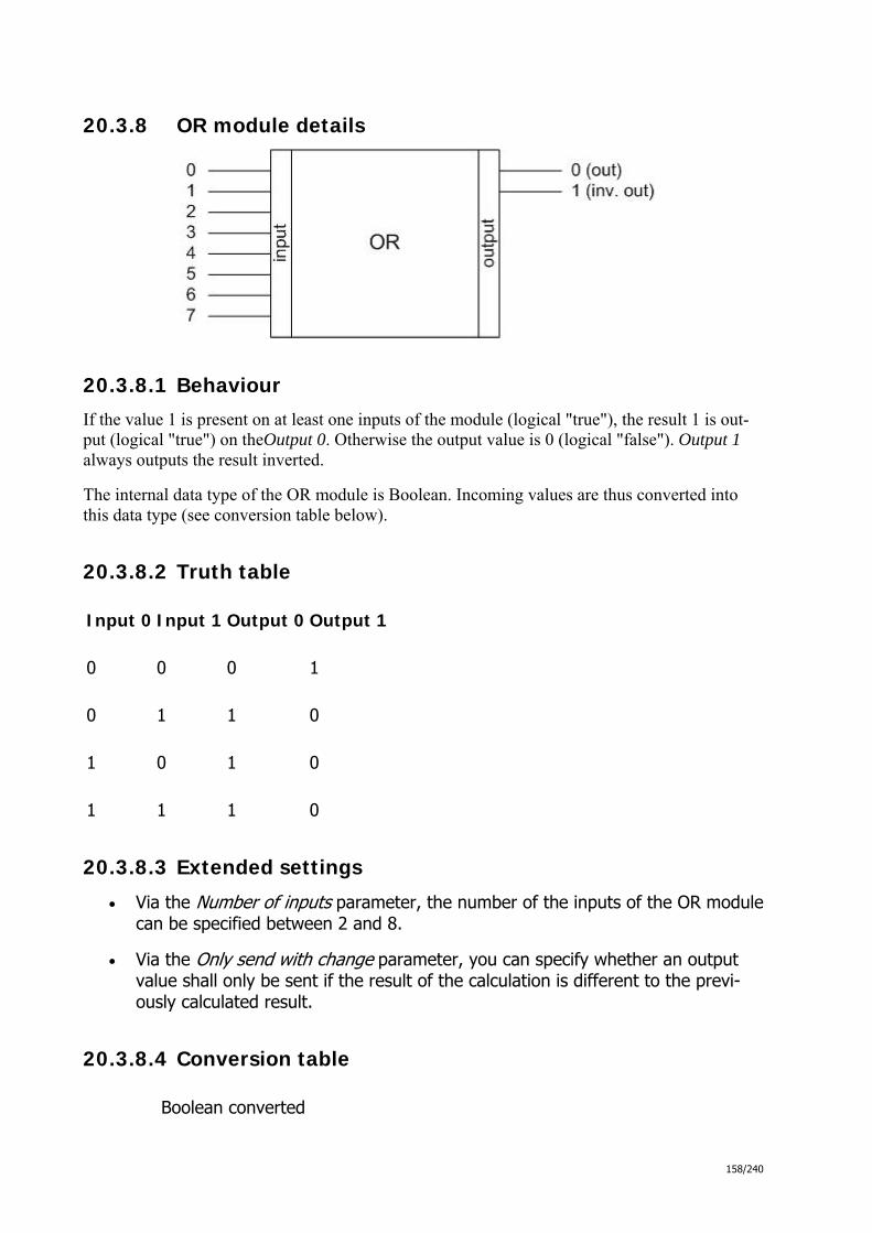
158/240
20.3.8 OR module details
20.3.8.1 Behaviour
If the value 1 is present on at least one inputs of the module (logical "true"), the result 1 is out-put (logical "true") on theOutput 0. Otherwise the output value is 0 (logical "false"). Output 1 always outputs the result inverted.
The internal data type of the OR module is Boolean. Incoming values are thus converted into this data type (see conversion table below).
20.3.8.2 Truth table
Input 0 Input 1 Output 0 Output 1
0 0 0 1
0 1 1 0
1 0 1 0
1 1 1 0
20.3.8.3 Extended settings
Via the Number of inputs parameter, the number of the inputs of the OR module can be specified between 2 and 8.
Via the Only send with change parameter, you can specify whether an output value shall only be sent if the result of the calculation is different to the previ-ously calculated result.
20.3.8.4 Conversion table
Boolean converted
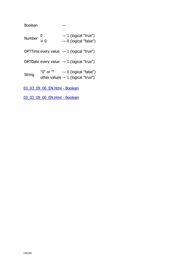
159/240
Boolean ---
Number 0 ≠ 0
→ →
1 (logical "true")0 (logical "false")
DPTTime every value → 1 (logical "true")
DPTDate every value → 1 (logical "true")
String "0" or "" other values
→ →
0 (logical "false")1 (logical "true")
03_03_09_00_EN.html - Boolean
03_03_09_00_EN.html - Boolean

160/240
20.3.9 XOR module details
20.3.9.1 Behaviour
If the value 1 is present on an odd number of inputs (logical "true"), the result 1 is output (logi-cal "true") on theOutput 0. Otherwise the output value is 0 (logical "false"). Output 1 always outputs the result inverted.
The internal data type of the XOR module is Boolean. Incoming values are thus converted into this data type (see conversion table below).
20.3.9.2 Truth table
Input 0 Input 1 Output 0 Output 1
0 0 0 1
0 1 1 0
1 0 1 0
1 1 0 1
20.3.9.3 Extended settings
Via the Number of inputs parameter, the number of the inputs of the XOR mo-dule can be specified between 2 and 8.
Via the Only send with change parameter, you can specify whether an output value shall only be sent if the result of the calculation is different to the previ-ously calculated result.
20.3.9.4 Conversion table
Boolean converted

161/240
Boolean ---
Number 0 ≠ 0
→ →
1 (logical "true")0 (logical "false")
DPTTime every value → 1 (logical "true")
DPTDate every value → 1 (logical "true")
String "0" or "" other values
→ →
0 (logical "false")1 (logical "true")
03_03_09_00_EN.html - Boolean
03_03_09_00_EN.html - Boolean

162/240
20.3.10 NOT module details
20.3.10.1 Behaviour
If the value 1 is present on the Input 0 (logical "true"), the result 0 is output (logical "false") on the Output 0 . If the value 0 is present on the input (logical "false"), the result 1 is output (logi-cal "true").
The internal data type of the NOT module is Boolean. Incoming values are thus converted into this data type (see conversion table below).
20.3.10.2 Truth table
Input 0 Output 0
0 1
1 0
20.3.10.3 Extended settings
Via the Only send with change parameter, you can specify whether an output value shall only be sent if the result of the calculation is different to the previously calculated result.
20.3.10.4 Conversion table
Boolean converted
Boolean ---
Number 0 ≠ 0
→ →
1 (logical "true")0 (logical "false")
DPTTime every value → 1 (logical "true")
DPTDate every value → 1 (logical "true")
String "0" or "" → 0 (logical "false")

163/240
other values → 1 (logical "true")
03_03_09_00_EN.html - Boolean
03_03_09_00_EN.html - Vergleicher

164/240
20.3.11 "Equal" module details
20.3.11.1 Behaviour
The module compares the values at both of the inputs. If the values are identical, the result 1 (logical "true") is output on the Output 0. Otherwise the output value is 0 (logical "false"). Out-put 1 always outputs the result inverted.
If necessary, incoming values are converted into the internal data type of the module before the comparison (see conversion table below). Thus, observe the selection of a correct internal data type!
20.3.11.2 Extended settings
Via the Internal data type parameter, you can specify the internal data type of the module.
Via the Only send with change parameter, you can specify whether an output value shall only be sent if the result of the calculation is different to the previ-ously calculated result.
20.3.11.3 Conversion table
Boolean (converted)
Number (converted)
DPTTime (converted)
DPTDate (converted)
String (converted)
Boolean --- true false
→ →
10
every va-lue
---
Current time
Current date
true false
→→
"1""0"
Number 0 ≠ 0
→ →
truefalse
---
every va-lue (as millise-cond since 1.1.1970)
→
Time of day, if possible; otherwise 00:00 Hours
Date, if possible; otherwise 1.1.1970
Text analo-gue to number
DPTTime true Millisecondssince 1.1.1970
--- 1.1.1970 Text analo-gue to time of

165/240
day
DPTDate true Number 12:00:00 AM --- Text analo-gue to date
String "0" or "" other
→ →
false true
Number, if possible; otherwise 0
Time of day, if possible;otherwise 00:00 Hours
Date, if possible; otherwise 1.1.1970
---
03_03_09_00_EN.html - Vergleicher
03_03_09_00_EN.html - Vergleicher

166/240
20.3.12 "Not equal" module details
20.3.12.1 Behaviour
The module compares the values at the inputs. If the values are not identical, the result 1 (logi-cal "true") is output on the Output 0. Otherwise the output value is 0 (logical "false"). Output 1 always outputs the result inverted.
If necessary, incoming values are converted into the internal data type of the module before the comparison (see conversion table below). Thus, observe the selection of a correct internal data type!
20.3.12.2 Extended settings
Via the Internal data type parameter, you can specify the internal data type of the module.
Via the Only send with change parameter, you can specify whether an output value shall only be sent if the result of the calculation is different to the previ-ously calculated result.
20.3.12.3 Conversion table
Boolean (converted)
Number (converted)
DPTTime (converted)
DPTDate (converted)
String (converted)
Boolean --- true false
→ →
10
every va-lue
---
Current time
Current date
true false
→→
"1""0"
Number 0 ≠ 0
→ →
truefalse
---
every va-lue (as millise-cond since 1.1.1970)
→
Time of day, if possible; otherwise 00:00 Hours
Date, if possible; otherwise 1.1.1970
Text analo-gue to number
DPTTime true Millisecondssince 1.1.1970
--- 1.1.1970 Text analo-gue to time of

167/240
day
DPTDate true Number 12:00:00 AM --- Text analo-gue to date
String "0" or "" other
→ →
false true
Number, if possible; otherwise 0
Time of day, if possible;otherwise 00:00 Hours
Date, if possible; otherwise 1.1.1970
---
03_03_09_00_EN.html - Vergleicher
03_03_09_00_EN.html - Vergleicher

168/240
20.3.13 "Greater" module details
20.3.13.1 Behaviour
The module compares the values at the inputs. If the value of the Input 0 is greater than the va-lue of the Input 1, the result 1 (logical "true") is output on the Output 0. Otherwise the output value is 0 (logical "false"). Output 1 always outputs the result inverted.
If necessary, incoming values are converted into the internal data type of the module before the comparison (see conversion table below). Thus, observe the selection of a correct internal data type!
The comparison is dependent on the internal data type of the module and is executed in the fol-lowing way:
Internal data type Comparison rule Example
Number Nummer comparison 5 > 3 → true
Time Time comparison 16:00 > 15:30 → true
Date Date comparison 17.07.2009 > 1.1.1970 → true
String String length comparison "ComfortPanel" > "priOn" → true
20.3.13.2 Extended settings
Via the Internal data type parameter, you can specify the internal data type of the module.
Via the Only send with change parameter, you can specify whether an output value shall only be sent if the result of the calculation is different to the previ-ously calculated result.
20.3.13.3 Conversion table
Boolean (converted)
Number (converted)
DPTTime (converted)
DPTDate (converted)
String (converted)
Boolean --- true false
→ →
10
every va-lue
---
Current time
Current date
true false
→→
"1""0"

169/240
Number 0 ≠ 0
→ →
true false
---
every va-lue (as millise-cond since 1.1.1970)
→
Time of day, if possible; otherwise 00:00 Hours
Date, if possible; otherwise 1.1.1970
Text analo-gue to number
DPTTime true Millisecondssince 1.1.1970
--- 1.1.1970
Text analo-gue to time of day
DPTDate true Number 12:00:00 AM --- Text analo-gue to date
String "0" or "" other
→ →
false true
Number, if possible; otherwise 0
Time of day, if possible;otherwise 00:00 Hours
Date, if possible; otherwise 1.1.1970
---
03_03_09_00_EN.html - Vergleicher
03_03_09_00_EN.html - Vergleicher
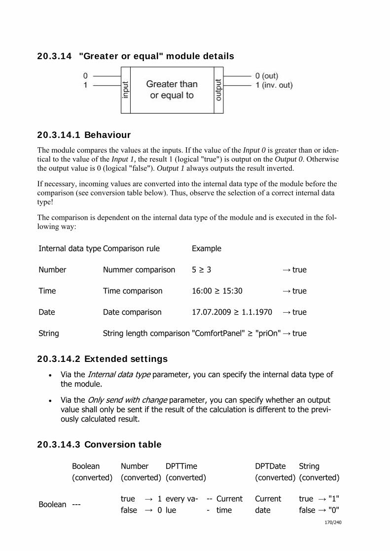
170/240
20.3.14 "Greater or equal" module details
20.3.14.1 Behaviour
The module compares the values at the inputs. If the value of the Input 0 is greater than or iden-tical to the value of the Input 1, the result 1 (logical "true") is output on the Output 0. Otherwise the output value is 0 (logical "false"). Output 1 always outputs the result inverted.
If necessary, incoming values are converted into the internal data type of the module before the comparison (see conversion table below). Thus, observe the selection of a correct internal data type!
The comparison is dependent on the internal data type of the module and is executed in the fol-lowing way:
Internal data type Comparison rule Example
Number Nummer comparison 5 ≥ 3 → true
Time Time comparison 16:00 ≥ 15:30 → true
Date Date comparison 17.07.2009 ≥ 1.1.1970 → true
String String length comparison "ComfortPanel" ≥ "priOn" → true
20.3.14.2 Extended settings
Via the Internal data type parameter, you can specify the internal data type of the module.
Via the Only send with change parameter, you can specify whether an output value shall only be sent if the result of the calculation is different to the previ-ously calculated result.
20.3.14.3 Conversion table
Boolean (converted)
Number (converted)
DPTTime (converted)
DPTDate (converted)
String (converted)
Boolean --- true false
→ →
10
every va-lue
---
Current time
Current date
true false
→→
"1""0"

171/240
Number 0 ≠ 0
→ →
true false
---
every va-lue (as millise-cond since 1.1.1970)
→
Time of day, if possible; otherwise 00:00 Hours
Date, if possible; otherwise 1.1.1970
Text analo-gue to number
DPTTime true Millisecondssince 1.1.1970
--- 1.1.1970
Text analo-gue to time of day
DPTDate true Number 12:00:00 AM --- Text analo-gue to date
String "0" or "" other
→ →
false true
Number, if possible; otherwise 0
Time of day, if possible;otherwise 00:00 Hours
Date, if possible; otherwise 1.1.1970
---
03_03_09_00_EN.html - Vergleicher
03_03_09_00_EN.html - Vergleicher

172/240
20.3.15 "Less" module details
20.3.15.1 Behaviour
The module compares the values at the inputs. If the value of the Input 0 is less than the value of the Input 1, the result 1 (logical "true") is output on the Output 0. Otherwise the output value is 0 (logical "false"). Output 1 always outputs the result inverted.
If necessary, incoming values are converted into the internal data type of the module before the comparison (see conversion table below). Thus, observe the selection of a correct internal data type!
The comparison is dependent on the internal data type of the module and is executed in the fol-lowing way:
Internal data type Comparison rule Example
Number Nummer comparison 5 < 3 → false
Time Time comparison 16:00 < 15:30 → false
Date Date comparison 17.07.2009 < 1.1.1970 → false
String String length comparison "ComfortPanel" < "priOn" → false
20.3.15.2 Extended settings
Via the Internal data type parameter, you can specify the internal data type of the module.
Via the Only send with change parameter, you can specify whether an output value shall only be sent if the result of the calculation is different to the previ-ously calculated result.
20.3.15.3 Conversion table
Boolean (converted)
Number (converted)
DPTTime (converted)
DPTDate (converted)
String (converted)
Boolean --- true false
→ →
10
every va-lue
---
Current time
Current date
true false
→→
"1""0"

173/240
Number 0 ≠ 0
→ →
true false
---
every va-lue (as millise-cond since 1.1.1970)
→
Time of day, if possible; otherwise 00:00 Hours
Date, if possible; otherwise 1.1.1970
Text analo-gue to number
DPTTime true Millisecondssince 1.1.1970
--- 1.1.1970
Text analo-gue to time of day
DPTDate true Number 12:00:00 AM --- Text analo-gue to date
String "0" or "" other
→ →
false true
Number, if possible; otherwise 0
Time of day, if possible;otherwise 00:00 Hours
Date, if possible; otherwise 1.1.1970
---
03_03_09_00_EN.html - Vergleicher
03_03_09_00_EN.html - Vergleicher

174/240
20.3.16 "Less or equal" module details
20.3.16.1 Behaviour
The module compares the values at the inputs. If the value of the Input 0 is less than or identical to the value of the Input 1, the result 1 (logical "true") is output on the Output 0. Otherwise the output value is 0 (logical "false"). Output 1 always outputs the result inverted.
If necessary, incoming values are converted into the internal data type of the module before the comparison (see conversion table below). Thus, observe the selection of a correct internal data type!
The comparison is dependent on the internal data type of the module and is executed in the fol-lowing way:
Internal data type Comparison rule Example
Number Nummer comparison 5 ≤ 3 → false
Time Time comparison 16:00 ≤ 15:30 → false
Date Date comparison 17.07.2009 ≤ 1.1.1970 → false
String String length comparison "ComfortPanel" ≤ "priOn" → false
20.3.16.2 Extended settings
Via the Internal data type parameter, you can specify the internal data type of the module.
Via the Only send with change parameter, you can specify whether an output value shall only be sent if the result of the calculation is different to the previ-ously calculated result.
20.3.16.3 Conversion table
Boolean (converted)
Number (converted)
DPTTime (converted)
DPTDate (converted)
String (converted)
Boolean --- true false
→ →
10
every va-lue
---
Current time
Current date
true false
→→
"1""0"

175/240
Number 0 ≠ 0
→ →
true false
---
every va-lue (as millise-cond since 1.1.1970)
→
Time of day, if possible; otherwise 00:00 Hours
Date, if possible; otherwise 1.1.1970
Text analo-gue to number
DPTTime true Millisecondssince 1.1.1970
--- 1.1.1970
Text analo-gue to time of day
DPTDate true Number 12:00:00 AM --- Text analo-gue to date
String "0" or "" other
→ →
false true
Number, if possible; otherwise 0
Time of day, if possible;otherwise 00:00 Hours
Date, if possible; otherwise 1.1.1970
---
03_03_09_00_EN.html - Vergleicher
03_03_09_00_EN.html - Vergleicher

176/240
20.3.17 Area tester (internal) module details
20.3.17.1 Behaviour
The module checks whether the incoming comparison value on Input 0 lies between two limit values. The limit values are defined by the Input 1 and the Input 2. If the comparison value is between the limit values, the result 1 (logical "true") is output on Output 0. Otherwise the output value is 0 (logical "false"). Output 1 always outputs the result inverted. If the limit values are invalidly configured (e.g. upper limit less than lower limit) the result 1 (logical "true") is output on Output 2.
If necessary, incoming values are converted into the internal data type of the module before the comparison (see conversion table below). Thus, observe the selection of a correct internal data type!
The comparison is dependent on the internal data type of the module and is executed in the fol-lowing way:
Internal data ty-pe
Comparison rule Example
Number Nummer comparison 3 ≤ 5 ≤ 7 → true
Time Time comparison 15:30 ≤ 16:00 ≤ 19:00 → true
Date Date comparison 1.1.1970 ≤ 19.2.1985 ≤ 17.5.2009 → true
String String length compari-son
"priOn" ≤ "priOn" ≤ "ComfortPa-nel"
→ true
20.3.17.2 Extended settings
Via the Internal data type parameter, you can specify the internal data type of the module.
Via the Only send with change parameter, you can specify whether an output value shall only be sent if the result of the calculation is different to the previ-ously calculated result.
20.3.17.3 Conversion table

177/240
Boolean (converted)
Number (converted)
DPTTime (converted)
DPTDate (converted)
String (converted)
Boolean --- true false
→→
10
every va-lue
---
Current time
Current date
truefalse
→→
"1""0"
Number 0 ≠ 0
→ →
true false
---
every va-lue (as millise-cond since 1.1.1970)
→
Time of day, if possible; otherwise 00:00 Hours
Date, if possible; otherwise 1.1.1970
Text analo-gue to number
DPTTime true Millisecondssince 1.1.1970
--- 1.1.1970
Text analo-gue to time of day
DPTDate true Number 12:00:00 AM --- Text analo-gue to date
String "0" or "" other
→ →
false true
Number, if possible; otherwise 0
Time of day, if possible;otherwise 00:00 Hours
Date, if possible; otherwise 1.1.1970
---
03_03_09_00_EN.html - Vergleicher
03_03_09_00_EN.html - Vergleicher

178/240
20.3.18 Area tester (external) module details
20.3.18.1 Behaviour
The module checks whether the incoming comparison value on Input 0 lies outside two limit values. The limit values are defined by the Input 1 and the Input 2. If the comparison value is outside the limit values, the result 1 (logical "true") is output on Output 0. Otherwise the output value is 0 (logical "false"). Output 1 always outputs the result inverted. If the limit values are invalidly configured (e.g. upper limit less than lower limit) the result 1 (logical "true") is output on Output 2.
If necessary, incoming values are converted into the internal data type of the module before the comparison (see conversion table below). Thus, observe the selection of a correct internal data type!
The comparison is dependent on the internal data type of the module and is executed in the fol-lowing way:
Internal data type
Comparison rule Example
Number Nummer comparison 3 ≤ 9 ≤ 7 → false
Time Time comparison 15:30 ≤ 21:10 ≤ 19:00 → false
Date Date comparison 1.1.1970 ≤ 29.12.2009 ≤ 17.5.2009
→ false
String String length compari-son
"priOn" ≤ "" ≤ "ComfortPanel" → false
20.3.18.2 Extended settings
Via the Internal data type parameter, you can specify the internal data type of the module.
Via the Only send with change parameter, you can specify whether an output value shall only be sent if the result of the calculation is different to the previ-ously calculated result.
20.3.18.3 Conversion table

179/240
Boolean (converted)
Number (converted)
DPTTime (converted)
DPTDate (converted)
String (converted)
Boolean --- true false
→→
10
every va-lue
---
Current time
Current date
truefalse
→→
"1""0"
Number 0 ≠ 0
→ →
true false
---
every va-lue (as millise-cond since 1.1.1970)
→
Time of day, if possible; otherwise 00:00 Hours
Date, if possible; otherwise 1.1.1970
Text analo-gue to number
DPTTime true Millisecondssince 1.1.1970
--- 1.1.1970
Text analo-gue to time of day
DPTDate true Number 12:00:00 AM --- Text analo-gue to date
String "0" or "" other
→ →
false true
Number, if possible; otherwise 0
Time of day, if possible;otherwise 00:00 Hours
Date, if possible; otherwise 1.1.1970
---
03_03_09_00_EN.html - Vergleicher
03_03_09_00_EN.html - Vergleicher

180/240
20.3.19 Details about threshold values with hysteresis
20.3.19.1 Behaviour
The module checks whether the incoming comparison value on Input 0 lies above or below a threshold value. In contrast to the Greater/Less comparator, a certain tolerance range can be defined (hysteresis). The approach direction of the comparison values (from above or below) to the threshold is also taken into account. This logic module can be used to generate exact logic signals from slowly executing processes, for example, for the switching signal of a thermostat-controlled heating control.
A lower and upper threshold are required for this logic module. The thresholds are defined via Input 1 and Input 2 .
Results are output as follows on the outputs (see also the graphic below):
If the comparison value first exceeds the lower and then the upper threshold, thus crossing the tolerance range from below to above, the result 1 (logical "true") is output on the Output 0. If the comparison value subsequently falls be-low the lower threshold again, the output Pin 3 is reset to 0 (condition for Out-put 1, see below).
If the comparison value first falls below the upper and then the lower threshold, thus crossing the tolerance range from above to below, the result 1 (logical "true") is output on the Output 1. If the comparison value subsequently exceeds the upper threshold again, the Output 1 is reset to 0 (condition for Output 0, see above).
On the Output 2 the result 1 is output (logical "true"), as soon as the compari-son value generally exceeds the upper threshold (without condition). Otherwise the output value is 0 (logical "false").
On the Output 3 the result 1 is output (logical "true"), as soon as the compari-son value generally falls below the lower threshold (without condition). Otherwi-se the output value is 0 (logical "false").
If the limit values are invalidly configured (e.g. upper limit less than lower limit) the result 1 (logical "true") is output on Output 4.
The internal data type of this module is Number. If necessary, incoming values are converted into the internal data type before the comparison (see conversion table below). Thus, observe the selection of a correct internal data type!

181/240
20.3.19.2 Truth table
1 2 3 4
Output 0
0 0 1 1 1 1 0 0 0
Output 1
0 0 0 0 0 0 1 1 1
Output 2
0 0 1 1 0 0 0 0 0
Output 3
1 0 0 0 0 0 1 1 0
20.3.19.3 Extended settings
Via the Only send with change parameter, you can specify whether an output value shall only be sent if the result of the calculation is different to the previously calculated result.
20.3.19.4 Conversion table
Number (converted)
Boolean true false
→ →
1 0
Number ---

182/240
DPTTime Milliseconds since 1.1.1970
DPTDate Number
String Number, if possible; otherwise 0
03_03_09_00_EN.html - Vergleicher
03_03_09_00_EN.html - Algebraisch

183/240
20.3.20 Adder details
20.3.20.1 Behaviour
The module adds the values of the inputs and outputs the result on the Output 0 .
If necessary, incoming values are converted into the internal data type of the module before the addition (see conversion table below). Thus, observe the selection of a correct internal data ty-pe!
The comparison is dependent on the internal data type of the module and is executed in the fol-lowing way:
Internal data type
Procedure Example
Number Mathematical additi-on
1 + 2 = 3
Time Calendrical addition 15:30 + 01:10 = 16:40
Date Calendrical addition 05.02.2009 + 03.00.0000
= 08.02.2009
String Concatenation of the strings
"ComfortPanel " + "is not a priOn"
="ComfortPanel is not a priOn"
20.3.20.2 Extended settings
Via the Internal data type parameter, you can specify the internal data type of the module.
Via the Number of inputs parameter, you can specify the number of inputs.
Via the Only send with change parameter, you can specify whether an output value shall only be sent if the result of the calculation is different to the previ-ously calculated result.

184/240
20.3.20.3 Conversion table
Boolean (converted)
Number (converted)
DPTTime (converted)
DPTDate (converted)
String (converted)
Boolean --- true false
→ →
10
every va-lue
---
Current time
Current date
true false
→→
"1""0"
Number 0 ≠ 0
→ →
truefalse
---
every va-lue (as millise-cond since 1.1.1970)
→
Time of day, if possible; otherwise 00:00 Hours
Date, if possible; otherwise 1.1.1970
Text analo-gue to number
DPTTime true Millisecondssince 1.1.1970
--- 1.1.1970
Text analo-gue to time of day
DPTDate true Number 12:00:00 AM --- Text analo-gue to date
String "0" or "" other
→ →
falsetrue
Number, if possible; otherwise 0
Time of day, if possible;otherwise 00:00 Hours
Date, if possible; otherwise 1.1.1970
---
03_03_09_00_EN.html - Algebraisch
03_03_09_00_EN.html - Algebraisch
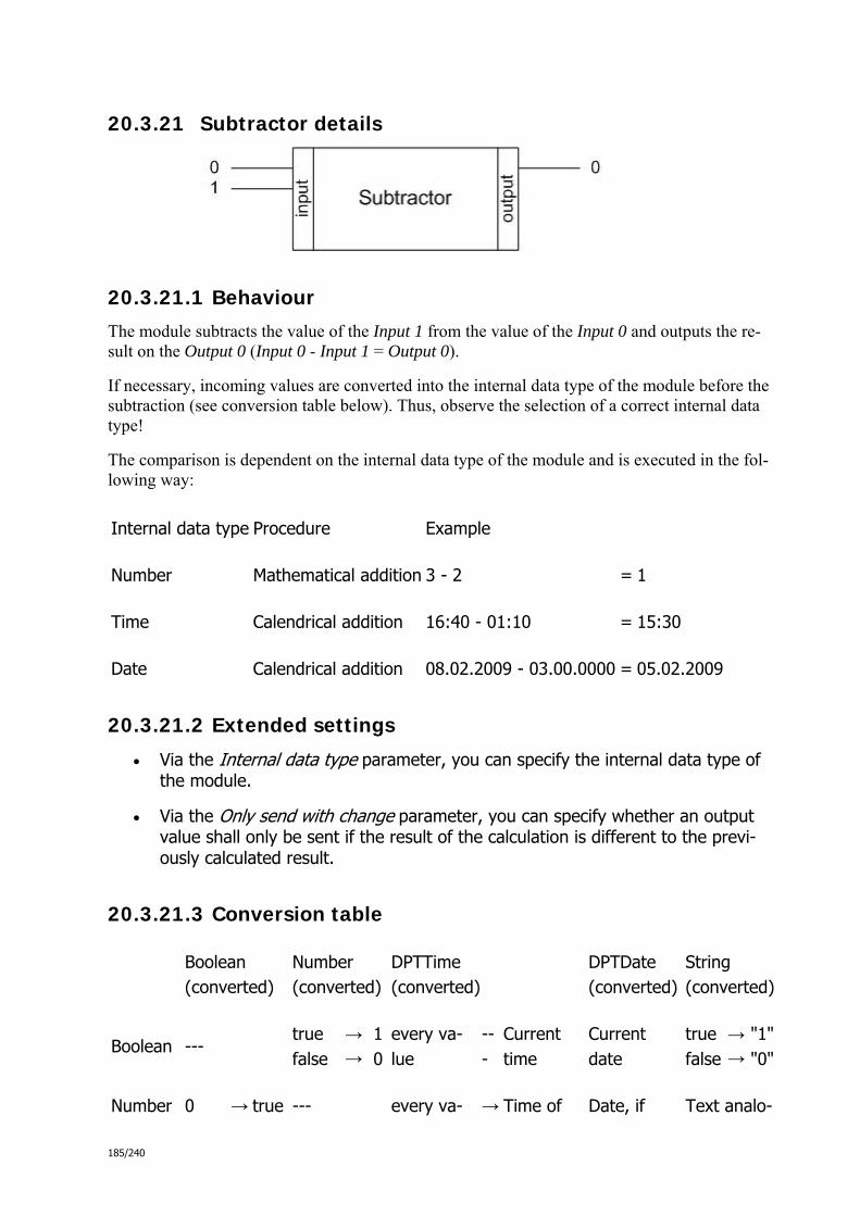
185/240
20.3.21 Subtractor details
20.3.21.1 Behaviour
The module subtracts the value of the Input 1 from the value of the Input 0 and outputs the re-sult on the Output 0 (Input 0 - Input 1 = Output 0).
If necessary, incoming values are converted into the internal data type of the module before the subtraction (see conversion table below). Thus, observe the selection of a correct internal data type!
The comparison is dependent on the internal data type of the module and is executed in the fol-lowing way:
Internal data type Procedure Example
Number Mathematical addition 3 - 2 = 1
Time Calendrical addition 16:40 - 01:10 = 15:30
Date Calendrical addition 08.02.2009 - 03.00.0000 = 05.02.2009
20.3.21.2 Extended settings
Via the Internal data type parameter, you can specify the internal data type of the module.
Via the Only send with change parameter, you can specify whether an output value shall only be sent if the result of the calculation is different to the previ-ously calculated result.
20.3.21.3 Conversion table
Boolean (converted)
Number (converted)
DPTTime (converted)
DPTDate (converted)
String (converted)
Boolean --- true false
→→
10
every va-lue
---
Current time
Current date
truefalse
→→
"1""0"
Number 0 → true --- every va- → Time of Date, if Text analo-
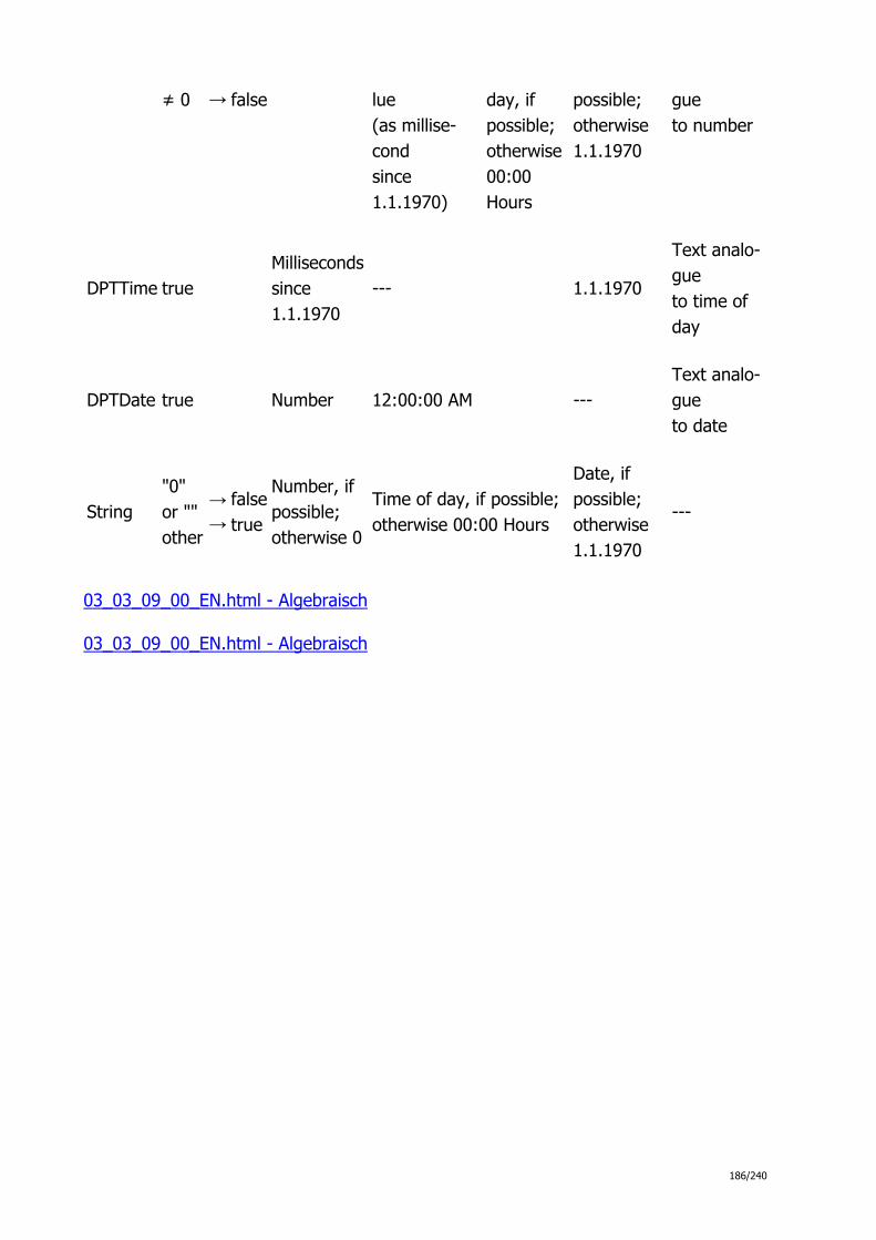
186/240
≠ 0 → false lue (as millise-cond since 1.1.1970)
day, if possible; otherwise 00:00 Hours
possible; otherwise 1.1.1970
gue to number
DPTTime true Millisecondssince 1.1.1970
--- 1.1.1970
Text analo-gue to time of day
DPTDate true Number 12:00:00 AM --- Text analo-gue to date
String "0" or "" other
→ →
falsetrue
Number, if possible; otherwise 0
Time of day, if possible;otherwise 00:00 Hours
Date, if possible; otherwise 1.1.1970
---
03_03_09_00_EN.html - Algebraisch
03_03_09_00_EN.html - Algebraisch

187/240
20.3.22 Multiplier details
20.3.22.1 Behaviour
The module multiplies the values of the inputs and outputs the result on the Output 0 .
The internal data type of this module is Number. If necessary, incoming values are converted into the internal data type before the multiplication (see conversion table below).
20.3.22.2 Extended settings
Via the Number of inputs parameter, you can specify the number of inputs.
Via the Only send with change parameter, you can specify whether an output value shall only be sent if the result of the calculation is different to the previ-ously calculated result.
20.3.22.3 Conversion table
Boolean (converted)
Number (converted)
DPTTime (converted)
DPTDate (converted)
String (converted)
Boolean --- true false
→→
10
every va-lue
---
Current time
Current date
truefalse
→→
"1""0"
Number 0 ≠ 0
→ →
true false
---
every va-lue (as millise-cond since 1.1.1970)
→
Time of day, if possible; otherwise 00:00 Hours
Date, if possible; otherwise 1.1.1970
Text analo-gue to number
DPTTime true Millisecondssince 1.1.1970
--- 1.1.1970 Text analo-gue to time of

188/240
day
DPTDate true Number 12:00:00 AM --- Text analo-gue to date
String "0" or "" other
→ →
falsetrue
Number, if possible; otherwise 0
Time of day, if possible;otherwise 00:00 Hours
Date, if possible; otherwise 1.1.1970
---
03_03_09_00_EN.html - Algebraisch
03_03_09_00_EN.html - Algebraisch
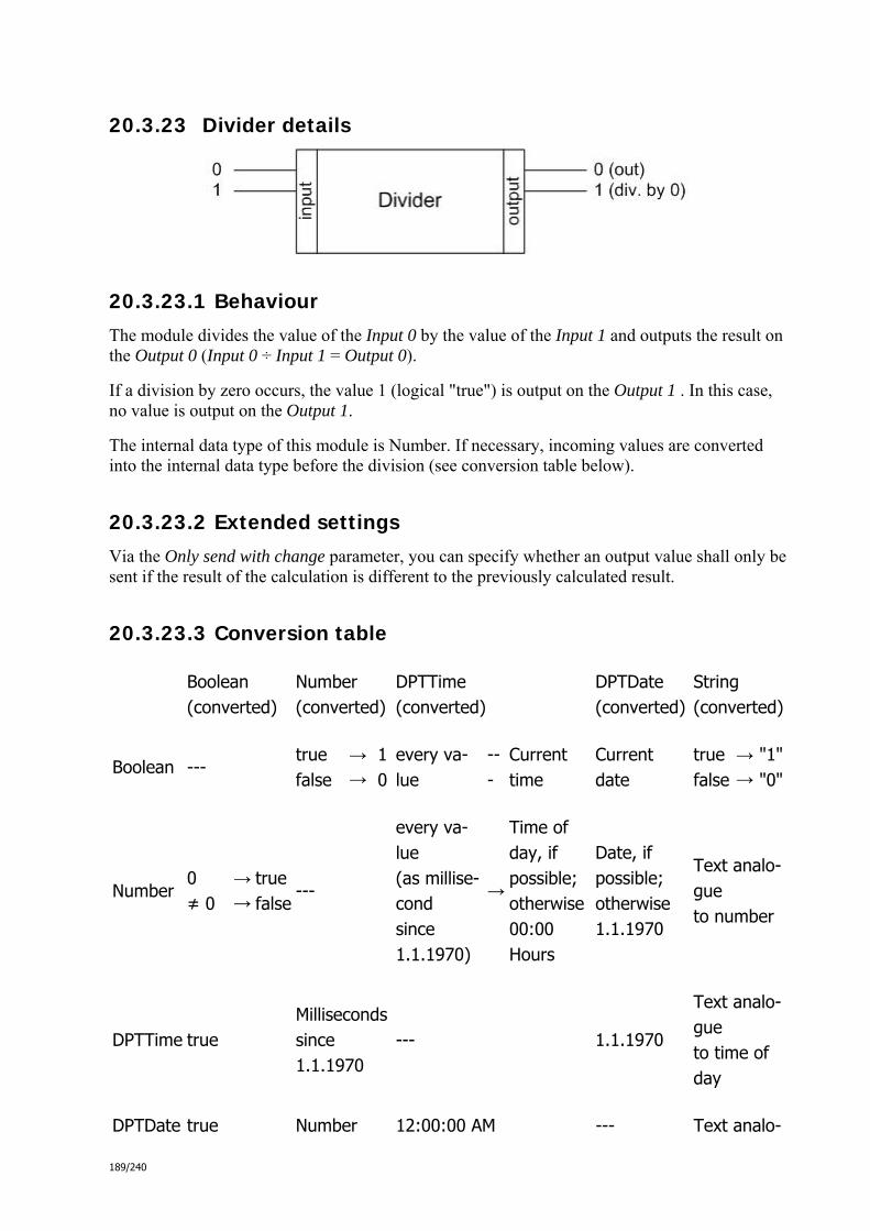
189/240
20.3.23 Divider details
20.3.23.1 Behaviour
The module divides the value of the Input 0 by the value of the Input 1 and outputs the result on the Output 0 (Input 0 ÷ Input 1 = Output 0).
If a division by zero occurs, the value 1 (logical "true") is output on the Output 1 . In this case, no value is output on the Output 1.
The internal data type of this module is Number. If necessary, incoming values are converted into the internal data type before the division (see conversion table below).
20.3.23.2 Extended settings
Via the Only send with change parameter, you can specify whether an output value shall only be sent if the result of the calculation is different to the previously calculated result.
20.3.23.3 Conversion table
Boolean (converted)
Number (converted)
DPTTime (converted)
DPTDate (converted)
String (converted)
Boolean --- true false
→→
10
every va-lue
---
Current time
Current date
truefalse
→→
"1""0"
Number 0 ≠ 0
→ →
true false
---
every va-lue (as millise-cond since 1.1.1970)
→
Time of day, if possible; otherwise 00:00 Hours
Date, if possible; otherwise 1.1.1970
Text analo-gue to number
DPTTime true Millisecondssince 1.1.1970
--- 1.1.1970
Text analo-gue to time of day
DPTDate true Number 12:00:00 AM --- Text analo-

190/240
gue to date
String "0" or "" other
→ →
falsetrue
Number, if possible; otherwise 0
Time of day, if possible;otherwise 00:00 Hours
Date, if possible; otherwise 1.1.1970
---
03_03_09_00_EN.html - Algebraisch
03_03_09_00_EN.html - Algebraisch
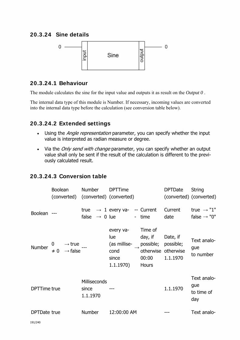
191/240
20.3.24 Sine details
20.3.24.1 Behaviour
The module calculates the sine for the input value and outputs it as result on the Output 0 .
The internal data type of this module is Number. If necessary, incoming values are converted into the internal data type before the calculation (see conversion table below).
20.3.24.2 Extended settings
Using the Angle representation parameter, you can specify whether the input value is interpreted as radian measure or degree.
Via the Only send with change parameter, you can specify whether an output value shall only be sent if the result of the calculation is different to the previ-ously calculated result.
20.3.24.3 Conversion table
Boolean (converted)
Number (converted)
DPTTime (converted)
DPTDate (converted)
String (converted)
Boolean --- true false
→→
10
every va-lue
---
Current time
Current date
truefalse
→→
"1""0"
Number 0 ≠ 0
→ →
true false
---
every va-lue (as millise-cond since 1.1.1970)
→
Time of day, if possible; otherwise 00:00 Hours
Date, if possible; otherwise 1.1.1970
Text analo-gue to number
DPTTime true Millisecondssince 1.1.1970
--- 1.1.1970
Text analo-gue to time of day
DPTDate true Number 12:00:00 AM --- Text analo-

192/240
gue to date
String "0" or "" other
→ →
falsetrue
Number, if possible; otherwise 0
Time of day, if possible;otherwise 00:00 Hours
Date, if possible; otherwise 1.1.1970
---
03_03_09_00_EN.html - Algebraisch
03_03_09_00_EN.html - Algebraisch
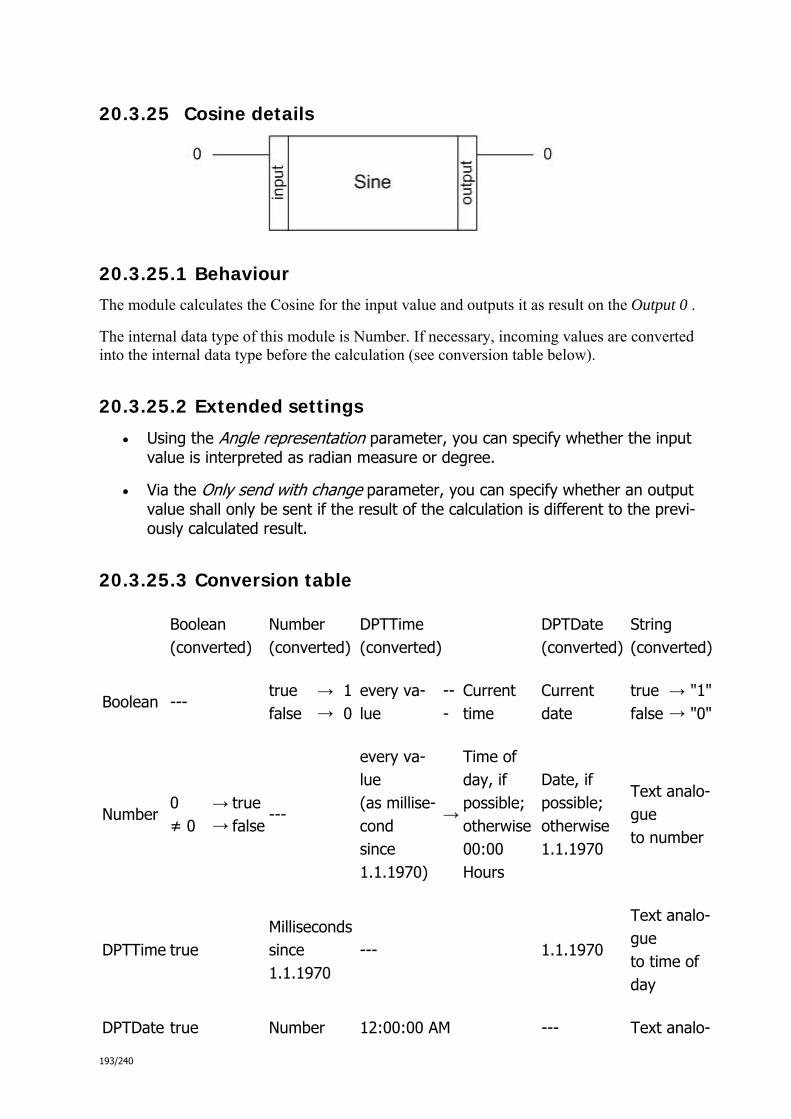
193/240
20.3.25 Cosine details
20.3.25.1 Behaviour
The module calculates the Cosine for the input value and outputs it as result on the Output 0 .
The internal data type of this module is Number. If necessary, incoming values are converted into the internal data type before the calculation (see conversion table below).
20.3.25.2 Extended settings
Using the Angle representation parameter, you can specify whether the input value is interpreted as radian measure or degree.
Via the Only send with change parameter, you can specify whether an output value shall only be sent if the result of the calculation is different to the previ-ously calculated result.
20.3.25.3 Conversion table
Boolean (converted)
Number (converted)
DPTTime (converted)
DPTDate (converted)
String (converted)
Boolean --- true false
→→
10
every va-lue
---
Current time
Current date
truefalse
→→
"1""0"
Number 0 ≠ 0
→ →
true false
---
every va-lue (as millise-cond since 1.1.1970)
→
Time of day, if possible; otherwise 00:00 Hours
Date, if possible; otherwise 1.1.1970
Text analo-gue to number
DPTTime true Millisecondssince 1.1.1970
--- 1.1.1970
Text analo-gue to time of day
DPTDate true Number 12:00:00 AM --- Text analo-

194/240
gue to date
String "0" or "" other
→ →
falsetrue
Number, if possible; otherwise 0
Time of day, if possible;otherwise 00:00 Hours
Date, if possible; otherwise 1.1.1970
---
03_03_09_00_EN.html - Algebraisch
03_03_09_00_EN.html - Algebraisch

195/240
20.3.26 Root function details
20.3.26.1 Behaviour
The module calculates the nth root of the input value and outputs it as result on the Output 0 .
If a negative input value is present on the input, the value 1 (logical "true") is output on the Out-put 1 . In this case, no value is output on the Output 0.
The internal data type of this module is Number. If necessary, incoming values are converted into the internal data type before the calculation (see conversion table below).
20.3.26.2 Extended settings
You can specify to which exponent the root shall be calculated (e.g. 2 for square root) using the Root exponent parameter.
Via the Only send with change parameter, you can specify whether an output value shall only be sent if the result of the calculation is different to the previ-ously calculated result.
20.3.26.3 Conversion table
Boolean (converted)
Number (converted)
DPTTime (converted)
DPTDate (converted)
String (converted)
Boolean --- true false
→→
10
every va-lue
---
Current time
Current date
truefalse
→→
"1""0"
Number 0 ≠ 0
→ →
true false
---
every va-lue (as millise-cond since 1.1.1970)
→
Time of day, if possible; otherwise 00:00 Hours
Date, if possible; otherwise 1.1.1970
Text analo-gue to number
DPTTime true Millisecondssince 1.1.1970
--- 1.1.1970
Text analo-gue to time of day

196/240
DPTDate true Number 12:00:00 AM --- Text analo-gue to date
String "0" or "" other
→ →
falsetrue
Number, if possible; otherwise 0
Time of day, if possible;otherwise 00:00 Hours
Date, if possible; otherwise 1.1.1970
---
03_03_09_00_EN.html - Algebraisch
03_03_09_00_EN.html - Algebraisch

197/240
20.3.27 Details about the Power function (x to the y)
20.3.27.1 Behaviour
The module calculates a specific power of the input value and outputs it as result on the Output 0 .
If the result of the calculation is invalid, the value 1 (logical "true") is output on the Output 1. In this case, no value is output on the Output 0.
The internal data type of this module is Number. If necessary, incoming values are converted into the internal data type before the calculation (see conversion table below).
20.3.27.2 Extended settings
You can specify to which exponent the power shall be calculated (e.g. 2 for x²) using the Exponent parameter.
Via the Only send with change parameter, you can specify whether an output value shall only be sent if the result of the calculation is different to the previ-ously calculated result.
20.3.27.3 Conversion table
Boolean (converted)
Number (converted)
DPTTime (converted)
DPTDate (converted)
String (converted)
Boolean --- true false
→→
10
every va-lue
---
Current time
Current date
truefalse
→→
"1""0"
Number 0 ≠ 0
→ →
true false
---
every va-lue (as millise-cond since 1.1.1970)
→
Time of day, if possible; otherwise 00:00 Hours
Date, if possible; otherwise 1.1.1970
Text analo-gue to number
DPTTime true Millisecondssince 1.1.1970
--- 1.1.1970 Text analo-gue to time of
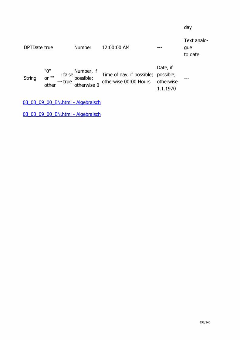
198/240
day
DPTDate true Number 12:00:00 AM --- Text analo-gue to date
String "0" or "" other
→ →
falsetrue
Number, if possible; otherwise 0
Time of day, if possible;otherwise 00:00 Hours
Date, if possible; otherwise 1.1.1970
---
03_03_09_00_EN.html - Algebraisch
03_03_09_00_EN.html - Algebraisch

199/240
20.3.28 Logarithm details
20.3.28.1 Behaviour
The module calculates the logarithm base 10 of the input value and outputs the result on the Output 0 .
If an input value ≤ 0 is present on the input, the value 1 (logical "true") is output on the Output 1 . In this case, no value is output on the Output 0.
The internal data type of this module is Number. If necessary, incoming values are converted into the internal data type before the calculation (see conversion table below).
20.3.28.2 Extended settings
Via the Only send with change parameter, you can specify whether an output value shall only be sent if the result of the calculation is different to the previously calculated result.
20.3.28.3 Conversion table
Boolean (converted)
Number (converted)
DPTTime (converted)
DPTDate (converted)
String (converted)
Boolean --- true false
→→
10
every va-lue
---
Current time
Current date
truefalse
→→
"1""0"
Number 0 ≠ 0
→ →
true false
---
every va-lue (as millise-cond since 1.1.1970)
→
Time of day, if possible; otherwise 00:00 Hours
Date, if possible; otherwise 1.1.1970
Text analo-gue to number
DPTTime true Millisecondssince 1.1.1970
--- 1.1.1970
Text analo-gue to time of day
DPTDate true Number 12:00:00 AM --- Text analo-

200/240
gue to date
String "0" or "" other
→ →
falsetrue
Number, if possible; otherwise 0
Time of day, if possible;otherwise 00:00 Hours
Date, if possible; otherwise 1.1.1970
---
03_03_09_00_EN.html - Algebraisch
03_03_09_00_EN.html - Algebraisch

201/240
20.3.29 Natural logarithm details
20.3.29.1 Behaviour
The module calculates the logarithm base e of the input value and outputs the result on the Out-put 0 .
If an input value ≤ 0 is present on the input, the value 1 (logical "true") is output on the Output 1 . In this case, no value is output on the Output 1.
The internal data type of this module is Number. If necessary, incoming values are converted into the internal data type before the calculation (see conversion table below).
20.3.29.2 Extended settings
Via the Only send with change parameter, you can specify whether an output value shall only be sent if the result of the calculation is different to the previously calculated result.
20.3.29.3 Conversion table
Boolean (converted)
Number (converted)
DPTTime (converted)
DPTDate (converted)
String (converted)
Boolean --- true false
→→
10
every va-lue
---
Current time
Current date
truefalse
→→
"1""0"
Number 0 ≠ 0
→ →
true false
---
every va-lue (as millise-cond since 1.1.1970)
→
Time of day, if possible; otherwise 00:00 Hours
Date, if possible; otherwise 1.1.1970
Text analo-gue to number
DPTTime true Millisecondssince 1.1.1970
--- 1.1.1970
Text analo-gue to time of day
DPTDate true Number 12:00:00 AM --- Text analo-

202/240
gue to date
String "0" or "" other
→ →
falsetrue
Number, if possible; otherwise 0
Time of day, if possible;otherwise 00:00 Hours
Date, if possible; otherwise 1.1.1970
---
03_03_09_00_EN.html - Algebraisch
03_03_09_00_EN.html - Algebraisch

203/240
20.3.30 Exponential function details
20.3.30.1 Behaviour
The module calculates the exponential function of the input value and outputs the result on the Output 0 .
The internal data type of this module is Number. If necessary, incoming values are converted into the internal data type before the calculation (see conversion table below).
20.3.30.2 Extended settings
Via the Only send with change parameter, you can specify whether an output value shall only be sent if the result of the calculation is different to the previously calculated result.
20.3.30.3 Conversion table
Boolean (converted)
Number (converted)
DPTTime (converted)
DPTDate (converted)
String (converted)
Boolean --- true false
→→
10
every va-lue
---
Current time
Current date
truefalse
→→
"1""0"
Number 0 ≠ 0
→ →
true false
---
every va-lue (as millise-cond since 1.1.1970)
→
Time of day, if possible; otherwise 00:00 Hours
Date, if possible; otherwise 1.1.1970
Text analo-gue to number
DPTTime true Millisecondssince 1.1.1970
--- 1.1.1970
Text analo-gue to time of day
DPTDate true Number 12:00:00 AM --- Text analo-gue to date

204/240
String "0" or "" other
→ →
falsetrue
Number, if possible; otherwise 0
Time of day, if possible;otherwise 00:00 Hours
Date, if possible; otherwise 1.1.1970
---
03_03_09_00_EN.html - Algebraisch
03_03_09_00_EN.html - weitere_math

205/240
20.3.31 Details about the 2-point curve function
20.3.31.1 Behaviour
The module calculates the function value of the vale on Input 0 using a 2-point curve progressi-on and outputs the result ( f(Input 0) = y = Output 0 )on the Output 0. The curve progression is determined as linear slope between two points as follows (see also the graphic below):
The first point results from the values of the Input 1 (x-coordinate) and of the Input 2 (y-coordinate).
Analogue to this, the second point is defined by the values of the Input 3 (x-coordinate) and of the Input 4 (y-coordinate).
If the point coordinates are invalidly configured (e.g. x-values identical) the result 1 (logical "true") is output on Output 1.
The internal data type of the module is Number. If necessary, incoming values are converted into the internal data type before the calculation (see conversion table below).
20.3.31.2 Extended settings
This module has no additional setting options.

206/240
20.3.31.3 Conversion table
Number (converted)
Boolean true false
→ →
1 0
Number ---
DPTTime Milliseconds since 1.1.1970
DPTDate Number
String Number, if possible; otherwise 0
03_03_09_00_EN.html - weitere_math
03_03_09_00_EN.html - weitere_math
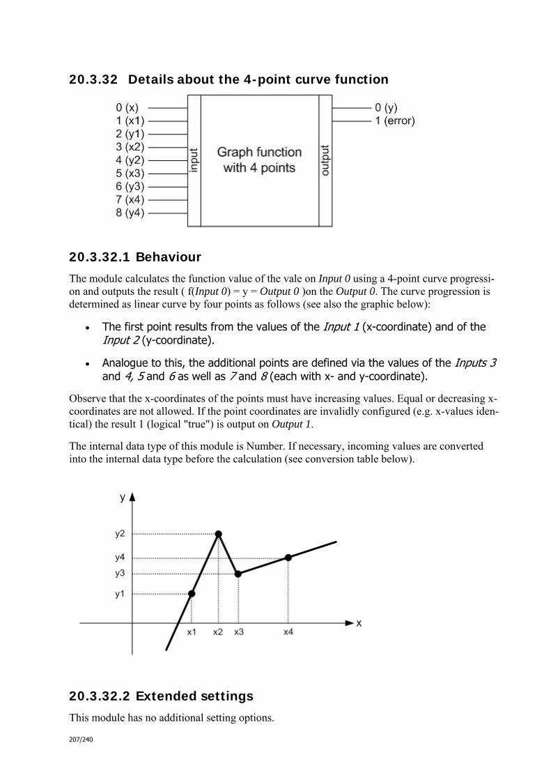
207/240
20.3.32 Details about the 4-point curve function
20.3.32.1 Behaviour
The module calculates the function value of the vale on Input 0 using a 4-point curve progressi-on and outputs the result ( f(Input 0) = y = Output 0 )on the Output 0. The curve progression is determined as linear curve by four points as follows (see also the graphic below):
The first point results from the values of the Input 1 (x-coordinate) and of the Input 2 (y-coordinate).
Analogue to this, the additional points are defined via the values of the Inputs 3 and 4, 5 and 6 as well as 7 and 8 (each with x- and y-coordinate).
Observe that the x-coordinates of the points must have increasing values. Equal or decreasing x-coordinates are not allowed. If the point coordinates are invalidly configured (e.g. x-values iden-tical) the result 1 (logical "true") is output on Output 1.
The internal data type of this module is Number. If necessary, incoming values are converted into the internal data type before the calculation (see conversion table below).
20.3.32.2 Extended settings
This module has no additional setting options.

208/240
20.3.32.3 Conversion table
Number (converted)
Boolean true false
→ →
1 0
Number ---
DPTTime Milliseconds since 1.1.1970
DPTDate Number
String Number, if possible; otherwise 0
03_03_09_00_EN.html - weitere_math
03_03_09_00_EN.html - weitere_math

209/240
20.3.33 Minimum value details
20.3.33.1 Behaviour
The module compares the values at the inputs and outputs the smallest value on the Output 0 as result.
If necessary, incoming values are converted into the internal data type of the module before the comparison (see conversion table below). Thus, observe the selection of a correct internal data type!
The comparison is dependent on the internal data type of the module and is executed in the fol-lowing way:
Internal data type
Comparison rule Example
Number Nummer comparison 5, 3 → Output 0 = 3
Time Time comparison 16:00, 15:30 → Output 0 = 15:30
Date Date comparison 17.07.2009, 1.1.1970 → Output 0 = 1.1.1970
String String length compari-son
"ComfortPanel", "pri-On"
→ Output 0 = "priOn"
20.3.33.2 Extended settings
Via the Internal data type parameter, you can specify the internal data type of the module.
Via the Number of inputs parameter, you can specify the number of inputs.
Via the Only send with change parameter, you can specify whether an output value shall only be sent if the result of the calculation is different to the previ-ously calculated result.
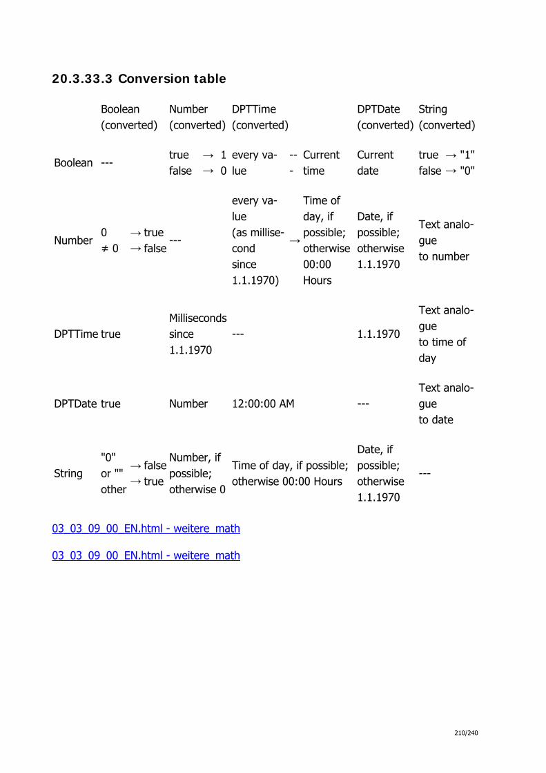
210/240
20.3.33.3 Conversion table
Boolean (converted)
Number (converted)
DPTTime (converted)
DPTDate (converted)
String (converted)
Boolean --- true false
→ →
10
every va-lue
---
Current time
Current date
true false
→→
"1""0"
Number 0 ≠ 0
→ →
truefalse
---
every va-lue (as millise-cond since 1.1.1970)
→
Time of day, if possible; otherwise 00:00 Hours
Date, if possible; otherwise 1.1.1970
Text analo-gue to number
DPTTime true Millisecondssince 1.1.1970
--- 1.1.1970
Text analo-gue to time of day
DPTDate true Number 12:00:00 AM --- Text analo-gue to date
String "0" or "" other
→ →
falsetrue
Number, if possible; otherwise 0
Time of day, if possible;otherwise 00:00 Hours
Date, if possible; otherwise 1.1.1970
---
03_03_09_00_EN.html - weitere_math
03_03_09_00_EN.html - weitere_math

211/240
20.3.34 Maximum value details
20.3.34.1 Behaviour
The module compares the values at the inputs and outputs the largest value on the Output 0 as result.
If necessary, incoming values are converted into the internal data type of the module before the comparison (see conversion table below). Thus, observe the selection of a correct internal data type!
The comparison is dependent on the internal data type of the module and is executed in the fol-lowing way:
Internal data type
Comparison rule Example
Number Nummer comparison 5, 3 → Output 0 = 5
Time Time comparison 16:00, 15:30 →Output 0 = 04:00:00 PM
Date Date comparison 17.07.2009, 1.1.1970 → Output 0 = 17.07.09
String String length compa-rison
"ComfortPanel", "priOn"
→Output 0 = "Comfort-Panel"
20.3.34.2 Extended settings
Via the Internal data type parameter, you can specify the internal data type of the module.
Via the Number of inputs parameter, you can specify the number of inputs.
Via the Only send with change parameter, you can specify whether an output value shall only be sent if the result of the calculation is different to the previ-ously calculated result.

212/240
20.3.34.3 Conversion table
Boolean (converted)
Number (converted)
DPTTime (converted)
DPTDate (converted)
String (converted)
Boolean --- true false
→ →
10
every va-lue
---
Current time
Current date
true false
→→
"1""0"
Number 0 ≠ 0
→ →
truefalse
---
every va-lue (as millise-cond since 1.1.1970)
→
Time of day, if possible; otherwise 00:00 Hours
Date, if possible; otherwise 1.1.1970
Text analo-gue to number
DPTTime true Millisecondssince 1.1.1970
--- 1.1.1970
Text analo-gue to time of day
DPTDate true Number 12:00:00 AM --- Text analo-gue to date
String "0" or "" other
→ →
falsetrue
Number, if possible; otherwise 0
Time of day, if possible;otherwise 00:00 Hours
Date, if possible; otherwise 1.1.1970
---
03_03_09_00_EN.html - weitere_math
03_03_09_00_EN.html - weitere_math

213/240
20.3.35 Absolute value details
20.3.35.1 Behaviour
The module calculates the absolute value of the value on Input 0 and outputs it to the Output 0 as result.
The internal data type of this module is Number. If necessary, incoming values are converted into the internal data type before the calculation (see conversion table below).
20.3.35.2 Extended settings
Via the Only send with change parameter, you can specify whether an output value shall only be sent if the result of the calculation is different to the previously calculated result.
20.3.35.3 Conversion table
Number (converted)
Boolean true false
→ →
1 0
Number ---
DPTTime Milliseconds since 1.1.1970
DPTDate Number
String Number, if possible; otherwise 0
03_03_09_00_EN.html - weitere_math
03_03_09_00_EN.html - weitere_math

214/240
20.3.36 Random value details
20.3.36.1 Behaviour
The module outputs random values from a specific value range on the Output 0. This can occur cyclically or upon receipt of the value 1 (logical "true") on Input 0 .
The data type of the Input 0 is Boolean. If necessary, incoming values are converted before the calculation (see conversion table below).
20.3.36.2 Extended settings
Via the Internal data type parameter, you can specify the internal data type of the module. The data type of the random values to be output is also defined by this.
Via the Cycle time parameter, you can specify in which intervals (seconds) ran-dom values shall be sent. Deactivate the associated control field if the values are not to be sent out cyclically.
Via the Lower limit and Upper limit parameters, you can specify the value range from which the random values shall originate.
Via the Only send with change parameter, you can specify whether an output value shall only be sent if the result of the calculation is different to the previ-ously calculated result.
20.3.36.3 Conversion table
Boolean (converted)
Boolean ---
Number 0 ≠ 0
→ →
true false
DPTTime true
DPTDate true

215/240
String "0" or "" other
→ →
false true
03_03_09_00_EN.html - weitere_math
03_03_09_00_EN.html - weitere_math
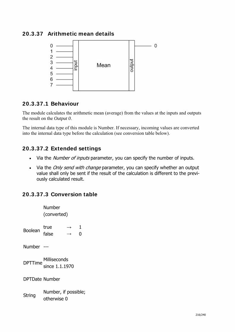
216/240
20.3.37 Arithmetic mean details
20.3.37.1 Behaviour
The module calculates the arithmetic mean (average) from the values at the inputs and outputs the result on the Output 0.
The internal data type of this module is Number. If necessary, incoming values are converted into the internal data type before the calculation (see conversion table below).
20.3.37.2 Extended settings
Via the Number of inputs parameter, you can specify the number of inputs.
Via the Only send with change parameter, you can specify whether an output value shall only be sent if the result of the calculation is different to the previ-ously calculated result.
20.3.37.3 Conversion table
Number (converted)
Boolean true false
→ →
1 0
Number ---
DPTTime Milliseconds since 1.1.1970
DPTDate Number
String Number, if possible; otherwise 0

217/240
03_03_09_00_EN.html - weitere_math
03_03_09_00_EN.html - weitere_math
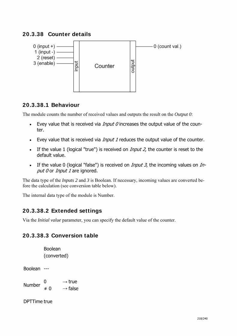
218/240
20.3.38 Counter details
20.3.38.1 Behaviour
The module counts the number of received values and outputs the result on the Output 0:
Evey value that is received via Input 0 increases the output value of the coun-ter.
Evey value that is received via Input 1 reduces the output value of the counter.
If the value 1 (logical "true") is received on Input 2, the counter is reset to the default value.
If the value 0 (logical "false") is received on Input 3, the incoming values on In-put 0 or Input 1 are ignored.
The data type of the Inputs 2 and 3 is Boolean. If necessary, incoming values are converted be-fore the calculation (see conversion table below).
The internal data type of the module is Number.
20.3.38.2 Extended settings
Via the Initial value parameter, you can specify the default value of the counter.
20.3.38.3 Conversion table
Boolean (converted)
Boolean ---
Number 0 ≠ 0
→ →
true false
DPTTime true

219/240
DPTDate true
String "0" or "" other
→ →
false true
03_03_09_00_EN.html - weitere_math
03_03_09_00_EN.html - Signalkontrolle

220/240
20.3.39 Delayer details
20.3.39.1 Behaviour
The module outputs every received value of the Input 0 again after expiry of a specific delay time on the Output 0. The delay time (in seconds) is defined via the Input 1. If an invalid delay time is specified (e.g. -1), the result 1 (logical "true") is output on the Output 1.
The data type of the Input 1 is Number. If necessary, incoming values are converted before the calculation (see conversion table below).
20.3.39.2 Extended settings
This module has no additional setting options.
20.3.39.3 Conversion table
Number (converted)
Boolean true false
→ →
1 0
Number ---
DPTTime Milliseconds since 1.1.1970
DPTDate Number
String Number, if possible; otherwise 0
03_03_09_00_EN.html - Signalkontrolle
03_03_09_00_EN.html - Signalkontrolle
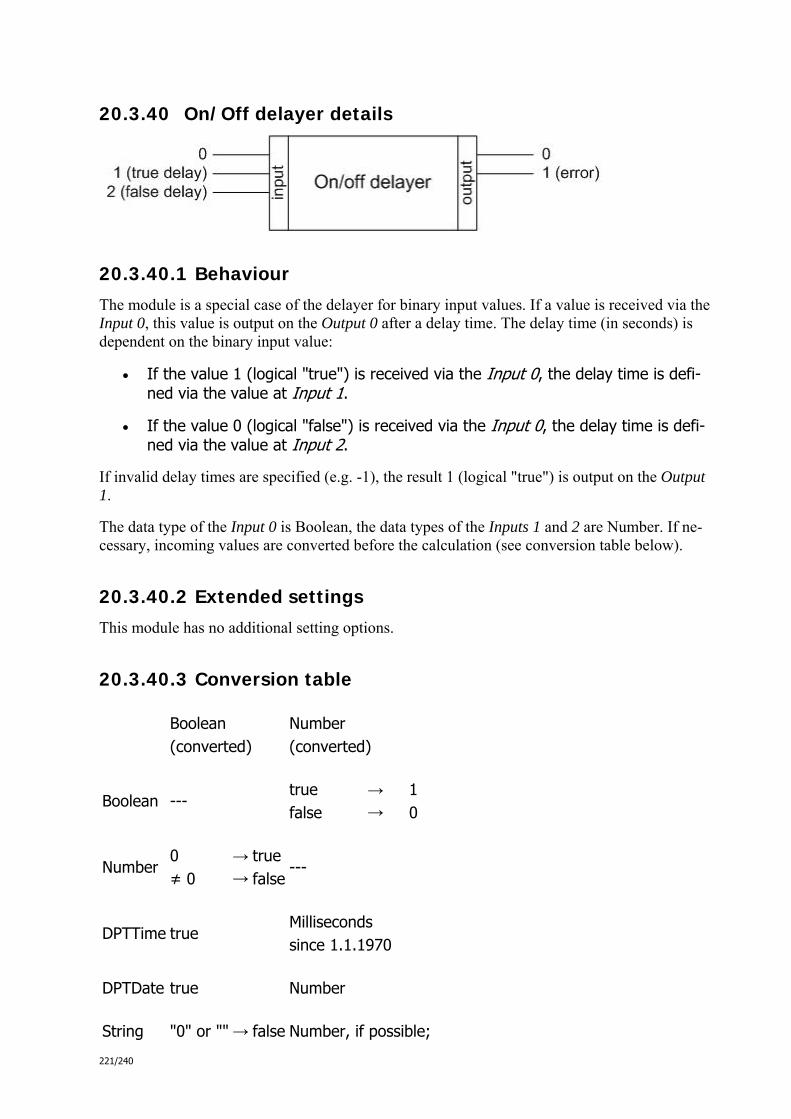
221/240
20.3.40 On/Off delayer details
20.3.40.1 Behaviour
The module is a special case of the delayer for binary input values. If a value is received via the Input 0, this value is output on the Output 0 after a delay time. The delay time (in seconds) is dependent on the binary input value:
If the value 1 (logical "true") is received via the Input 0, the delay time is defi-ned via the value at Input 1.
If the value 0 (logical "false") is received via the Input 0, the delay time is defi-ned via the value at Input 2.
If invalid delay times are specified (e.g. -1), the result 1 (logical "true") is output on the Output 1.
The data type of the Input 0 is Boolean, the data types of the Inputs 1 and 2 are Number. If ne-cessary, incoming values are converted before the calculation (see conversion table below).
20.3.40.2 Extended settings
This module has no additional setting options.
20.3.40.3 Conversion table
Boolean (converted)
Number (converted)
Boolean --- true false
→ →
1 0
Number 0 ≠ 0
→ →
true false
---
DPTTime true Milliseconds since 1.1.1970
DPTDate true Number
String "0" or "" → false Number, if possible;

222/240
other → true otherwise 0
03_03_09_00_EN.html - Signalkontrolle
03_03_09_00_EN.html - Signalkontrolle

223/240
20.3.41 Staircase lighting details
20.3.41.1 Behaviour
If this module receives the value 1 (logical "true") via the Input 0, it immediately outputs it on the Output 0. After expiry of a delay time, the value 0 (logical "false") is output on the Output 0. The delay time (in seconds) is dependent on the value at Input 1.
Via a value at Input 2 , a number of pulses can be defined that are output before expiry of the delay time on the Output 0. A pulse consists of a 0-1 combination with an interval of 0.5 se-conds between the values 0 an 1.
If invalid values are specified for the delay time or number of pulses (e.g. -1), the result 1 (logi-cal "true") is output on the Output 1.
The data type of the Input 0 is Boolean, the data types of the Inputs 1 and 2 are Number. If ne-cessary, incoming values are converted before the calculation (see conversion table below).
20.3.41.2 Extended settings
Via the Restart timer parameter, you can specify whether the delay time shall always be reset by the receipt of the value 1 via the Input 0.
20.3.41.3 Conversion table
Boolean (converted)
Number (converted)
Boolean --- true false
→ →
1 0
Number 0 ≠ 0
→ →
true false
---
DPTTime true Milliseconds since 1.1.1970
DPTDate true Number
String "0" or "" → →
false Number, if possible;

224/240
other true otherwise 0
03_03_09_00_EN.html - Signalkontrolle
03_03_09_00_EN.html - Signalkontrolle

225/240
20.3.42 Lock details
20.3.42.1 Behaviour
Every value (regardless of which data type) received via the Input 0, is immediately output again on Output 0 by this module, provided it is not locked. If the module is locked, received values are blocked until the module is opened again. When the module is opened the last recei-ved value is output. The lock can be activated and cancelled via the Input 1 .
The data type of the Input 1 is Boolean. If necessary, incoming values are converted before the calculation (see conversion table below).
20.3.42.2 Extended settings
Via the Operating mode parameter, you can specify whether the lock shall be activated by receipt of the value 0 or via the Input 1.
Via the Only send with change parameter, you can specify whether an output value shall only be sent if the current input value is different from the previously received input value.
20.3.42.3 Conversion table
Boolean (converted)
Boolean ---
Number 0 ≠ 0
→ →
true false
DPTTime true
DPTDate true
String "0" or "" other
→ →
false true
03_03_09_00_EN.html - Signalkontrolle

226/240
03_03_09_00_EN.html - Signalkontrolle

227/240
20.3.43 Filter details
20.3.43.1 Behaviour
The module can transfer Boolean values or lock those received via the Input 0. Lock means that the value at the Output 0 is not reset.
The behaviour can be set as follows via the Operating mode parameter:
The value 1 (logical "true") is transferred, the value 0 (logical "false") is locked.
The value 0 (logical "false") is transferred, the value 1 (logical "true") is locked.
Both the value 1 (logical "true") as well as the value 0 (logical "false") are trans-ferred.
The value 1 (logical "true") changes the value at the Output 0 (from 0 to 1 or vice versa), the value 0 (logical "false") is locked.
The value 0 (logical "false") changes the value at the Output 0 (from 0 to 1 or vice versa), the value 1 (logical "true") is locked.
Both the value 1 (logical "true"), as well as the value 0 (logical "false") change the value at the Output 0 (from 0 to 1 or vice versa).
The internal data type of the module is Boolean. If necessary, incoming values are converted before the calculation (see conversion table below).
20.3.43.2 Extended settings
Via the Operating mode parameter, you can specify how the module should behave (see above).
20.3.43.3 Conversion table
Boolean (converted)
Boolean ---
Number 0 ≠ 0
→ →
true false
DPTTime true

228/240
DPTDate true
String "0" or "" other
→ →
false true
03_03_09_00_EN.html - Signalkontrolle
03_03_09_00_EN.html - Signalkontrolle

229/240
20.3.44 Text filter details
20.3.44.1 Behaviour
This module can receive string values via the Output 0 and compare these using a LDAP filter string with the values at the Inputs 1 to 8. Using the key word "<compare_n"> in the LDAP filter string, the input can be selected with which the compare shall be executed (n: from 1 to 8).
If the incoming value and the comparison value are identical, the result 1 (logical "true") is out-put on the Output 0. Otherwise the output value is 0 (logical "false"). Output 1 always outputs the result inverted.
If the value 0 (logical "false") is received via the Input 9, the module is deactivated. The value 1 (logical "true") activates it again.
If there is a processing error (e.g. invalid LDAP filter string) the value 1 (logical "true") is out-put on the Output 2.
The internal data type of the module and of the Inputs 1 to 8 is String, the data type of the Input 9 is Boolean. If necessary, incoming values are converted before the calculation (see conversion table below).
20.3.44.2 Extended settings
Via the Only send with change parameter, you can specify whether an output value shall only be sent if the result of the calculation is different to the previ-ously calculated result.
You can define the LDAP filter string for the comparison using the Filter alpha-numeric character chain parameter.
Via theNumber of parameter, you can specify how many comparison values you want to allow. With the selection of different values, the number of inputs of the module changes similarly.

230/240
20.3.44.3 Conversion table
Boolean (converted)
String (converted)
Boolean --- true false
→→
"1""0"
Number 0 ≠ 0
→ →
true false
Text analogueto number
DPTTime true Text analogueto time of day
DPTDate true Text analogueto date
String "0" or "" other
→ →
false true
---
03_03_09_00_EN.html - Signalkontrolle
03_03_09_00_EN.html - Signalkontrolle

231/240
20.3.45 Text divider details
20.3.45.1 Behaviour
This module can receive string values via the Input 0 and divide these into partial strings . Its purpose is the division into the format:
Command +
Preamble +
Parameter 1 + Separator +
Parameter 2 + Separator +
…
Parameter 8 +
Postambel
The command is output via the Output 0 and the parameter (up to eight) via the Outputs 1 to 8. For this, the preamble, postamble and separator must be specified (see below).
If the value 0 (logical "false") is received via the Input 1, the module is deactivated. The value 1 (logical "true") activates it again.
If the logic module finds more than eight parameters in an incoming string, it outputs the value 1 (logical "true") on the Output 9 . If a en error occurs during the text division, the value 1 (logi-cal "true") is output on the Output 10.
The internal data type of the module and of the Input 0 is String, the data type of the Input 1 is Boolean. If necessary, incoming values are converted before the calculation (see conversion table below).
20.3.45.2 Extended settings
Via the parameters Preamble, Postambel and Separator, you can specify which

232/240
character strings shall serve as preamble, postamble and separator.
Via the Only send with change parameter, you can specify whether an output value shall only be sent if the result of the calculation is different to the previ-ously calculated result.
20.3.45.3 Conversion table
Boolean (converted)
String (converted)
Boolean --- true false
→→
"1""0"
Number 0 ≠ 0
→ →
true false
Text analogueto number
DPTTime true Text analogueto time of day
DPTDate true Text analogueto date
String "0" or "" other
→ →
false true
---
03_03_09_00_EN.html - Signalkontrolle
03_03_09_00_EN.html - Signalkontrolle
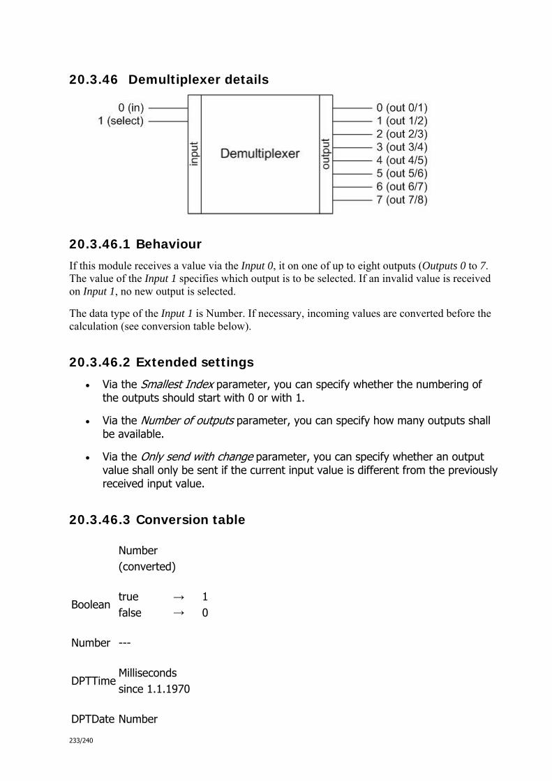
233/240
20.3.46 Demultiplexer details
20.3.46.1 Behaviour
If this module receives a value via the Input 0, it on one of up to eight outputs (Outputs 0 to 7. The value of the Input 1 specifies which output is to be selected. If an invalid value is received on Input 1, no new output is selected.
The data type of the Input 1 is Number. If necessary, incoming values are converted before the calculation (see conversion table below).
20.3.46.2 Extended settings
Via the Smallest Index parameter, you can specify whether the numbering of the outputs should start with 0 or with 1.
Via the Number of outputs parameter, you can specify how many outputs shall be available.
Via the Only send with change parameter, you can specify whether an output value shall only be sent if the current input value is different from the previously received input value.
20.3.46.3 Conversion table
Number (converted)
Boolean true false
→ →
1 0
Number ---
DPTTime Milliseconds since 1.1.1970
DPTDate Number

234/240
String Number, if possible; otherwise 0
03_03_09_00_EN.html - Signalkontrolle
03_03_09_00_EN.html - Signalkontrolle

235/240
20.3.47 Multiplexer details
20.3.47.1 Behaviour
If this module receives a value via one of the up to eight inputs (Input 0 to 7), it outputs this value on the Output 0. The value of the Input 8 specifies which input is to react to incoming values. If an invalid value is received on Input 8, no new input is selected. Once a new input is selected, the last received value there is output on Output 0.
The data type of the Input 8 is Number. If necessary, incoming values are converted before the calculation (see conversion table below).
20.3.47.2 Extended settings
Via the Smallest Index parameter, you can specify whether the numbering of the outputs should start with 0 or with 1.
Via the Number of inputs parameter, you can specify how many inputs shall be available.
Via the Only send with change parameter, you can specify whether an output value shall only be sent if the current input value is different from the previously received input value.
20.3.47.3 Conversion table
Number (converted)
Boolean true false
→ →
1 0
Number ---
DPTTime Milliseconds

236/240
since 1.1.1970
DPTDate Number
String Number, if possible; otherwise 0
03_03_09_00_EN.html - Signalkontrolle
03_03_09_00_EN.html - Signalkontrolle

237/240
20.3.48 Number of input details
20.3.48.1 Behaviour
If this module receives a value (regardless of which data type) via one of the up to eight inputs (Input 0 to 7), it outputs the index number of the received input on the Output 0. If the module receives values on multiple inputs simultaneously, the highest index number is output.
The internal data type of the module is Number. If necessary, incoming values are converted before the calculation (see conversion table below).
20.3.48.2 Extended settings
Via the Smallest Index parameter, you can specify whether the numbering of the outputs should start with 0 or with 1.
Via the Number of inputs parameter, you can specify how many inputs shall be available.
Via the Only send with change parameter, you can specify whether an output value shall only be sent if the result of the calculation is different to the previ-ously calculated result.
20.3.48.3 Conversion table
Number (converted)
Boolean true false
→ →
1 0
Number ---
DPTTime Milliseconds since 1.1.1970
DPTDate Number

238/240
String Number, if possible; otherwise 0
03_03_09_00_EN.html - Signalkontrolle
03_03_09_00_EN.html - Signalkontrolle

239/240
20.3.49 RS-Flip-Flop details
20.3.49.1 Behaviour
The RS-Flip-Flop behaves as follows:
If this module receives the value 1 (logical "true") via Input 0 and simultaneous-ly via Input 1 the value 0 (logical "false"), it outputs the value 1 (logical "true") on the Ausgang 0.
If this module receives the value 0 (logical "false") via Input 0 and simultane-ously via Input 1 the value 1 (logical "true"), the Ausgang 0 is reset to the value 0 (logical "false").
Output 1 always outputs the result inverted.
If this module receives the value 1 (logical "true") via both Input 0 and Input 1, no change of the output values occurs (illegal state). In this case, the value 1 (logical "true") is sent on the Output 2.
The internal data type of the module is Boolean. If necessary, incoming values are converted before the calculation (see conversion table below).
20.3.49.2 Truth table
Input 0 Input 1 Output 0 Output 1 Behaviour
0 0 Q Q' Hold status
0 1 0 1 Reset
1 0 1 0 Set
1 1 --- --- Not allowed
20.3.49.3 Extended settings
Via the Only send with change parameter, you can specify whether an output value shall only be sent if the result of the calculation is different to the previously calculated result.
20.3.49.4 Conversion table
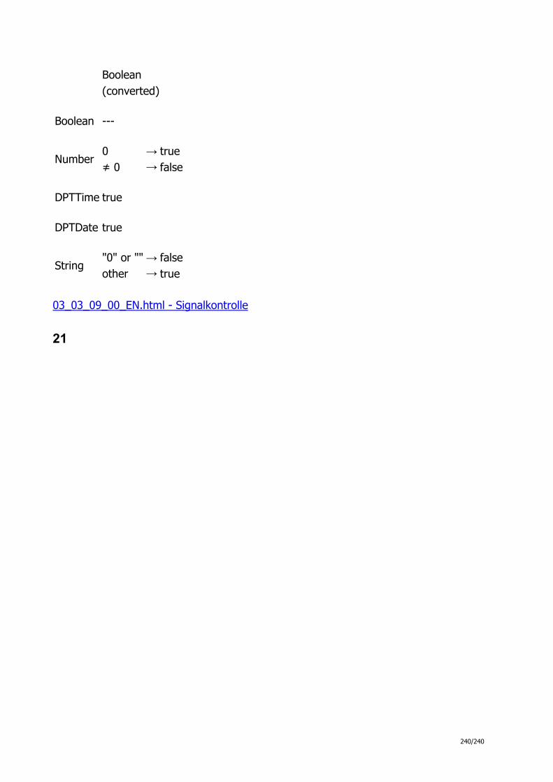
240/240
Boolean (converted)
Boolean ---
Number 0 ≠ 0
→ →
true false
DPTTime true
DPTDate true
String "0" or "" other
→ →
false true
03_03_09_00_EN.html - Signalkontrolle
21