production of single cell anode-supported sofc … · sel tunggal sofc mempunyai ketebalan 600µm...
TRANSCRIPT
PRODUCTION OF SINGLE CELL ANODE-SUPPORTED SOFC
USING NiO/YSZ-YSZ-LSM/YSZ POWDER MATERIALS
SULISTYO
A thesis submitted in fulfillment of the requirement for award the Degree of
Doctor of Philosophy
Faculty of Mechanical and Manufacturing Engineering
Universiti Tun Hussein Onn Malaysia
AUGUST, 2015

v
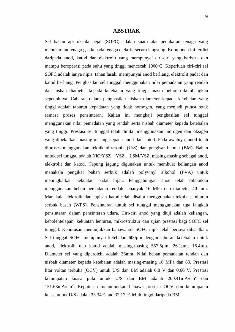
ABSTRACT
Solid oxide fuel cell (SOFC) is an energy conversion device that converts gas into
electricity directly. The components consist of anode, electrolyte and cathode which
have different properties and operate at high temperatures up to 1000 οC. SOFC
requires a thin, robust, porous anode, dense electrolyte and porous cathode.
Manufacturing of single cell using low compaction value and high diameter to
thickness ratio is yet to be developed. The challenge of the higher diameter to
thickness ratio is inhomogeneous density distribution which causes cracks during
sintering. This research investigates the manufacturing of single cell using low
compaction and high diameter to thickness ratio. The performance of single cell was
evaluated using hydrogen and oxygen that are supplied to the anode and cathode
respectively. Initially the anode was produced using ultrasonic (U/S) process and ball
mill (BM) process. The materials for single cell are NiO/YSZ, YSZ, LSM/YSZ as
anode, electrolyte and cathode, respectively. The cornstarch is used to create anode
porosity while the material binder of the powder is polyvinyl alcohol (PVA) to
increase green compact strength. The consolidation of anode was done using a low
compaction load of 16 MPa with a diameter of 40 mm. The electrolyte and cathode
layer were coated using wet powder spraying (WPS) technique. The sintering for
single cell used a three step air sintering. The characterizations of the anode include
porosity, permeability, bending strength, microstructure and these were tested to
evaluate the performance of the single cell SOFC. The results demonstrated that the
thin SOFC single cell was successfully obtained. The single cell SOFC has a
thickness of 600 µm where the distribution of thickness for the anode, electrolyte,
and cathode were 557.5 µm, 26.1 µm and 16.4 µm, respectively. The cell diameter
obtained was 36 mm. The low compaction load and the diameter to thickness ratio
were 16 MPa and 60, respectively. Performance of open circuit voltage (OCV) for
U/S and BM process is 0.8 V and 0.66 V, respectively. Power density performance
for U/S and BM process is 200.41mA/cm2 and 151.63mA/cm
2 respectively. The
results indicated that the performance of OCV and power density for U/S were
33.34% and 32.17 % higher than BM process.
vi
ABSTRAK
Sel bahan api oksida pejal (SOFC) adalah suatu alat penukaran tenaga yang
menukarkan tenaga gas kepada tenaga elektrik secara langsung. Komponen ini terdiri
daripada anod, katod dan elektrolit yang mempunyai ciri-ciri yang berbeza dan
mampu beroperasi pada suhu yang tinggi mencecah 1000oC. Keperluan ciri-ciri sel
SOFC adalah ianya nipis, tahan lasak, mempunyai anod berliang, elektrolit padat dan
katod berliang. Penghasilan sel tunggal menggunakan nilai pemadatan yang rendah
dan nisbah diameter kepada ketebalan yang tinggi masih belum dikembangkan
sepenuhnya. Cabaran dalam penghasilan nisbah diameter kepada ketebalan yang
tinggi adalah taburan kepadatan yang tidak homogen, yang menjadi punca retak
semasa proses pensinteran. Kajian ini mengkaji penghasilan sel tunggal
menggunakan nilai pemadatan yang rendah serta nisbah diameter kepada ketebalan
yang tinggi. Prestasi sel tunggal telah dinilai menggunakan hidrogen dan oksigen
yang dibekalkan masing-masing kepada anod dan katod. Pada awalnya, anod telah
diproses menggunakan teknik ultrasonik (U/S) dan pengisar bebola (BM). Bahan
untuk sel tunggal adalah NiO/YSZ – YSZ – LSM/YSZ, masing-masing sebagai anod,
elektrolit dan katod. Tepung jagung digunakan untuk membuat keliangan anod
manakala pengikat bahan serbuk adalah polyvinyl alkohol (PVA) untuk
meningkatkan kekuatan padat hijau. Penggabungan anod telah dilakukan
menggunakan beban pemadatan rendah sebanyak 16 MPa dan diameter 40 mm.
Manakala elektrolit dan lapisan katod telah disalut menggunakan teknik semburan
serbuk basah (WPS). Pensinteran untuk sel tunggal menggunakan tiga langkah
pensinteran dalam pensinteran udara. Ciri-ciri anod yang diuji adalah keliangan,
kebolehtelapan, kekuatan lenturan, mikrostruktur dan ujian prestasi bagi SOFC sel
tunggal. Keputusan menunjukkan bahawa sel SOFC nipis telah berjaya dihasilkan.
Sel tunggal SOFC mempunyai ketebalan 600µm dengan taburan ketebalan untuk
anod, elektrolit dan katod adalah masing-masing 557.5µm, 26.1µm, 16.4µm.
Diameter sel yang diperolehi adalah 36mm. Nilai beban pemadatan rendah dan
nisbah diameter kepada ketebalan adalah masing-masing 16 MPa dan 60. Prestasi
litar voltan terbuka (OCV) untuk U/S dan BM adalah 0.8 V dan 0.66 V. Prestasi
ketumpatan kuasa pula untuk U/S dan BM adalah 200.41mA/cm2 dan
151.63mA/cm2. Keputusan menunjukkan bahawa prestasi OCV dan ketumpatan
kuasa untuk U/S adalah 33.34% and 32.17 % lebih tinggi daripada BM.

vii
TABLE OF CONTENTS
TITLE i
DECLARATION ii
DEDICATION iii
ACKNOWLEDGEMENT iv
ABSTRACT v
ABSTRAK vi
TABLE OF CONTENTS vii
LIST OF TABLES xi
LIST OF FIGURE xii
LIST OF SIMBOLS AND ABBREVIATIONS xvii
LIST OF APPENDICES xxi
CHAPTER 1 INTRODUCTION 1
1.1 Research background 1
1.2 Problem statement 3
1.3 Objective 6
1.4 Scope of the research 7
1.5 Contribution to knowledge 8
1.6 Thesis layout 9

viii
CHAPTER 2 LITERATURE REVIEW 10
2.1 Introduction 10
2.2 Energy status and renewable energy 10
2.3 Fuel cell technology 11
2.4 Development progress of Solid Oxide Fuel Cell 13
2.5 Design of the SOFC single cell 15
2.6 SOFC material selection 17
2.6.1 Anode material 18
2.6.2 Electrolyte material 19
2.6.3 Cathode material 20
2.6.4 Pore former material 20
2.7 Production of SOFC 22
2.7.1 Powder process 24
2.7.1.1 Ball mill process 24
2.7.1.2 Ultrasonic process 25
2.7.2 Consolidation powder using uniaxial compaction 27
2.7.3 Ni as catalyst in anode 31
2.7.4 Electrolyte development 33
2.7.5 Cathode development 35
2.7.6 Sintering process 37
2.7.6.1 Mechanism of sintering process 38
2.7.6.2 Anode sintering 40
2.7.6.3 Electrolyte sintering 43
2.7.6.4 Cathode sintering 44
2.8 SOFC cell characterization 45
2.8.1 Porosity 45
2.8.2 Crystallite size 46
2.8.3 Permeability 47
2.8.4 Bending strength 49
2.8.5 Microstructure 50
2.8.6 Electrical properties 52
2.9 Summary 54

ix
CHAPTER 3 RESEARCH METHODOLOGY 56
3.1 Introduction 56
3.2 Flow chart of research methodology 56
3.3 Development of anode-supported SOFC 58
3.4 Characterization of sintered anode-supported SOFC 63
3.5 Development of SOFC electrolyte 69
3.6 Development of cathode layer 72
3.7 Performance of single cell of anode-supported SOFC 75
3.7.1 Installation of external conductor 76
3.7.2 Performance of single cell anode-supported SOFC 76
3.8 Summary 79
CHAPTER 4 RESULT AND DISCUSSION 80
4.1 Introduction 80
4.2 Powder process of anode material 80
4.3 Development of anode supported SOFC 83
4.3.1 Development of porous anode 83
4.3.2 The anode size 87
4.3.3 Compaction energy 90
4.3.4 Anode permeability 92
4.3.5 Bending strength of anode 94
4.3.6 Microstructure 98
4.3.7 EDS (Energy-dispersive X-ray spectroscopy)
analysis 101
4.3.8 XRD (X-Ray Diffraction) analysis 105
4.4 Development of electrolyte 107
4.4.1 Electrolyte characterization 110
4.5 Cathode development 116
4.5.1 Cathode sintering 117
4.5.2 Cathode characterization 117

x
4.6 Performance of single cell SOFC 121
4.6.1 Open Circuit Voltage (OCV) single cell 121
4.6.2. The power density of single cell 124
4.7 Summary 127
CHAPTER 5 CONCLUSIONS AND RECOMMENDATIONS 128
5.1 Conclusion 128
5.2 Contribution of the research 130
5.3 Recommendation for future work 130
REFERENCES 132
APPENDIX 152
PUBLICATIONS 175
VITAE 177

xi
LIST OF TABLES
2.1: Development generation Solid Oxide Fuel Cell in CFCL 14
2.2: Properties of starch as pore former 21
3.1: Material powders and pore former 59
3.2: Parameter process for an anode development 59
3.3: Specimen size for porosity, permeability and bending strength 63
3.4: Concentration of electrolyte suspension 70
3.5: Concentration of cathode suspension 73
3.6: Specification of material in testing single cell 76
4.1: The element of NiO/YSZ anode for BM process after sintering at
temperature of 1350 οC using EDS 101
4.2: The element of NiO/YSZ anode for U/S process after sintering at
temperature of 1350 οC using EDS 102

xii
LIST OF FIGURES
2.1 Schematic of SOFC planar, anode supported-, cathode
supported-, electrolyte supported SOFC type 15
2.2 Schematic of tubular SOFC, showing current flow
through the cell 16
2.3 Thermal decomposition of cornstarch using TGA with
different moisture content (%) heated at 5○C/min: (a) 0:
(b) 6.91; (c) 13.55; (d) 20.12; (e) 34.92; (f) 50.67 21
2.4 Schematic compaction processes (a) powder before
pressing and (b) powder after pressing 27
2.5 Schematic of three phase boundary (TPB) in anode-
electrolyte-interface 32
2.6 Illustration of mechanism of sintering process 38
2.7 Mechanism of atom diffusion in the ceramic material.
(a) Interstitial atom diffusion mechanism. (b) Vacancy
atom diffusion mechanism.(c) Energy barrier
which must be overcome if an atom can jump 39
2.8 Illustration of particle shrinkage, (a) before sintering,
(b) after sintering 42
2.9 Full width at half maximum (FWHM) at XRD pattern 47
2.10 Illustration path of the gas permeability 48
2.11 Illustration dense structure of anode 49
2.12 Comparison microstructure produced by (a)
Atmospheric Plasma Spraying (APS), (b) Wet Powder
Spraying process (WPS) 51

xiii
2.13 Schematic of single cell SOFC 52
3.1 (a) Flowchart research development SOFC 57
3.1 (b) Flowchart research development SOFC 58
3.2 (a) Ultrasonic batch (b) Ball mill (c) Mould
components 60
3.3 Sintering cycle of green compact anode 61
3.4 (a) Powder of NiO/YSZ after U/S & BM process, (b)
NiO/YSZ anode 62
3.5 Support equipment to measuree porosity (a) SG bottle,
(b) digital balance, (c) hot plate stirrer 64
3.6 The sample of specimen for porosity measurement 65
3.7 Equipment for permeability test 65
3.8 The sample of anode permeability specimen 66
3.9 The bending strength specimen 67
3.10 Bending test equipment 67
3.11 SEM equipment 68
3.12 XRD (X-Ray Diffraction) equipment 69
3.13 Sintering cycle SOFC electrolytes 71
3.14 (a) Bilayers consist of anode and electrolyte top view,
(b) two layers comprise anode and electrolyte front
view 72
3.15 The sintering cycle of SOFC cathode 74
3.16 (a) Bilayers consist of anode and electrolyte; three
layers cell consist of anode, electrolyte and cathode, (b)
three layers cell was compared with RM 50 cents front
view 74
3.17 Heating equipment (a) furncae, (b) oven 75
3.18 Schematic of SOFC test rig 77
3.19 Tube furnace for SOFC test rig 78
3.20 The SOFC single cell 78
3.21 SOFC test rig 78
4.1 Powder size of NiO/YSZ 81
4.2 Crystallite size of NiO/YSZ powder 83

xiv
4.3 Correlation of anode porosity and variation cornstarch
content after air sintering at 1350οC. US02 and BM02
are NiO/YSZ powder that were processed by ultrasonic
and ball mill using load compaction of 2
MPa,respectively 84
4.4 Correlation of anode porosity and load compaction
after air sintering at 1350 οC. Uscs5 and BMcs5 are
NiO/YSZ powder that were processed by ultrasonic
(US) and ball mill (BM) using cornstarch pore of 5
wt% 85
4.5 (a) Sintered anode, (b) Sintered anode crack 88
4.6 The shrinkage of the green compact anode after
sintering 89
4.7 Energy compaction of the anode at load compaction
variation 91
4.8 Correlation of anode porosity and anode permeability
using constant compaction of 16 MPa and cornstarch
pore former of 5 wt%, 10 wt%,15 wt%, 20 wt%, 30
wt% for U/S process and BM process 93
4.9 Correlation of anode porosity and anode bending
strength that was processed by using constant
compaction of 16 MPa and cornstarch pore former of 5
wt%, 10 wt%,15 wt%, 20 wt%, 30 wt% for U/S process
and BM process respectively. 95
4.10 Microstructure anode supported SOFC for compaction
load 16 MPa, sintering 1350 οC, pore former 5 wt%.
(a,b,c) U/S process, (d,e,f) BM process 98
4.11 Compounds in NiO/YSZ powder for U/S and BM
processes after sintering of 1350 οC 103
4.12 Diffraction pattern of NiO/YSZ powder before
sintering 105
4.13 Comparison of diffraction pattern sintered NiO/YSZ by
U/S and BM 106

xv
4.14 Bilayer of electrolyte and anode that were sintered one
cycle. There was seen warpage and electrolyte crack 108
4.15 Two step sintering electrolyte layer and anode
supported SOFC, top view, (b) front view 109
4.16 (a) Electrolyte surface sintered at 1250 οC, (b)
electrolyte surface sintered by at1350 οC, with holding
time 3 hours 110
4.17 (a) Polished electrolyte surface using low
magnification, (b) polished electrolyte surface using
high magnification 111
4.18 The cross section anode and electrolyte after sintering
process, red colour show the Zr atom, (a) Zr atom
distribute in the anode, (b) Zr atom was dense in the
electrolyte. 112
4.19 (a) Cross section interface anode-electrolyte, (b) the
interface anode–electrolyte and TPB (three phase
boundary) 113
4.20 The distribution atoms in the component sintered
electrolyte 115
4.21 The sintered cathode layer, (a) top view of cathode, (b)
front view of thee layers cell comprised anode,
electrolyte and cathode 116
4.22 Cross section of cathode using mapping technique (a)
La atoms appear in the cathode layer, (b) Sr atoms in
cathode layer (c) Mn atoms appear in cathode layer
(d) O atoms appear in the all layers 118
4.23 (a) The cross section of anode, electrolyte and cathode,
(b) cross section SOFC cell shows the size of
electrolyte and cathode 120
4.24 Microstructure of cathode surface shows the pore
distribution 120
4.25 Relationship between temperature and open circuit
voltage (OCV) single cell anode-supported SOFC 122

xvi
4.26 Relationship temperature and power density single cell
anode-supported SOFC by U/S process and BM
process 124

xvii
LIST OF SIMBOLS AND ABBREVIATIONS
AES Air Electrode Supported
AFC Alkaline Fuel Cell
AFL Anode Functional Layer
APS Atmospheric Plasma Spraying
ASR Area Specific Resistance
BCNO BaCe0.9Nd0.1O3-δ
BCY BaCe0.8Y0.2O3-δ
BCZY Ba0.98Ce0.6Zr0.2Y0.2O3-δ
BM Ball mill
BZCY7 Ba(Zr0.1Ce0.7)Y0.2O3-δ
CaO Calcium Oxide
CaSZ Calcium Stabilized Zirconia
CCS CO2 Capture and Storage
CSP Concentrated Solar Power
CFCL Ceramic Fuel Cells Limited, Australian SOFC company
CFL Cathode Functional Layer
CHP Combine Heat and Power
CO2 Carbon dioxide
CTE Coefficient of Thermal Expansion
CVD Chemical Vapor Deposition
DC Direct Current
ECN Energy research Centre of Nederland
EVD Electrochemical Vapour Deposition
EDS Energy Dispersive X-Ray Spectroscopy

xviii
Er2O3 erbium oxide
FWHM Full Width of the peak at Half of the Maximum intensity
GDC Gadolina Doped Ceria
GT Gigatons
HTSOFC High Temperature Solid Oxide Fuel Cell
IEA International Energy Agency
ICE Internal Combustion Engine
ITSOFC Intermediate Temperature Solid Oxide Fuel Cell
LaCoO3 Lanthanum cobalt oxide
L/A Length to the cross-sectional ratio
LSCF Lanthanum Strontium Cobalt Ferrum Oxide
LSCF/SDCC Lanthanum Strontium Cobalt Ferrum Oxide- Samarium Doped Ceria
Carbonate
LSM/YSZ Lanthanum Strontium Manganite-Yttria Stabilized Zirconia
LTSOFC Low Temperature Solid Oxide Fuel Cell
MA Mechanical Alloying
MCFC Molten Carbonate Fuel Cell
MEA Membrane Electrolyte Assembly
MHI Mitsubishi Heavy Industry
MnO2 mangan oxide
MPa Mega pascal
MW Megawatts
NASA National Aeronautics and Space Administration
NOx Nitrogen mono oxide
NiO/SDCC Nickel Oxide-Samarium Doped Ceria Carbonate
NiO/YSZ Nickel Oxide – Yttria Stabilized Zirconia
NiO/YSZ8 Nickel Oxide-Yttria Stabilized Zirconia 8 mole %
NiO/BCIO3 Nickel Oxide-Barium Cerium Indium Oxide
NOx Nitrogen mono oxide
OCV Open Circuit Voltage
PAFC Phosphoric Acid Fuel Cell
PEM Polymeric Electrolyte Membrane
PEMFC Polymeric Electrolyte Membrane Fuel Cell
PSA Particle Size Analyzer

xix
PV Photovoltaic
PVA Polyvinyl Alcohol
PVD Phycical Vapor Deposition
RADAR Radio Detection And Ranging systems
SEM Scanning Electron Microscopy
SDC Samarium Doped Ceria
ScSZ Scandia Stabilized Zirconia
SDCC Samarium Doped Ceria Carbonate
SOFC Solid Oxide Fuel Cell
SONAR Sound Navigation and Ranging
SOx Sulfur mono oxide
SWPG Siemens Westinghouse Power Generation
TEM Transmission Electron Microscopy
TGA Thermal Gravimetric Analyzer
TPB Triple Phase Boundary
TPBL Triple Phase Boundary Length
UK United Kingdom
U/S Ultrasonic
Vol Volume
VO2 Vanadium Oxide
wt Weight
WPS Wet Powder Spraying
WTI West Texas Intermediate
XRD X-Ray Diffraction
Y2O3 Yttrium Oxide
YSZ Yttria Stabilized Zirconia
YSZ8 Yttria Stabilized Zirconia 8 mole %
ZrO2 Zirconium dioxide
µm Micro meter, unit of length
µCT Micro Computer Topography
A The area of the layer
Cs Crystallite size
Co Cosntant
D Diffusion coefficient

xx
E The electrical potential difference
Eo
The standard-state reversible voltage
F Faraday’s constant
G Gibbs free energy
∆go The standard-state free energy change for reaction
∆p The pressure drop over the membrane
k Scherrer’s constant
m meter, unit of length
n Number of moles of electron transfer
P Maximum load
S/cm Siemens/ centimeter, unit of electric conductivity
T Temperature, K
t Thickness of specimen
V Bulk Volume
V Voltage, unit of electric voltage
Vs Volume of solid
w Width of specimen
Greek letters
λ The wavelength of CuKα radiation (1.5406 Å)
β The fullwidth of the peak at half of the maximum intensity (FWHM)
κ Permeability
θ The diffraction angle of the corresponding reflection
η The viscosity of the gas
Φ Porosity
Bending stress
xxi
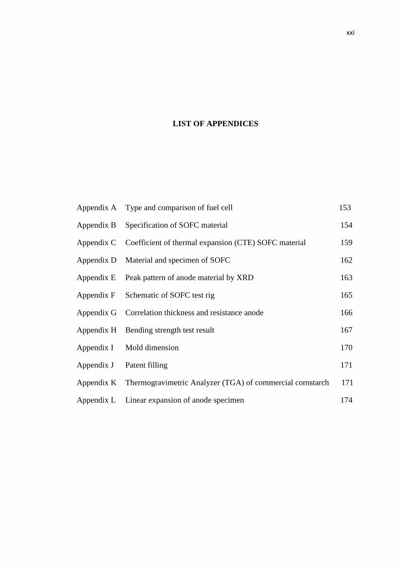
LIST OF APPENDICES
Appendix A Type and comparison of fuel cell 153
Appendix B Specification of SOFC material 154
Appendix C Coefficient of thermal expansion (CTE) SOFC material 159
Appendix D Material and specimen of SOFC 162
Appendix E Peak pattern of anode material by XRD 163
Appendix F Schematic of SOFC test rig 165
Appendix G Correlation thickness and resistance anode 166
Appendix H Bending strength test result 167
Appendix I Mold dimension 170
Appendix J Patent filling 171
Appendix K Thermogravimetric Analyzer (TGA) of commercial cornstarch 171
Appendix L Linear expansion of anode specimen 174
1
CHAPTER 1
INTRODUCTION
1.1 Research background
The energy crisis and greenhouse effect has attracted the development for alternative
energy. There were several types of renewable energy studied include the
geothermal, wave, wind and nuclear energies. Various researchers have worked in
developing devices that converts these energies into electricity. One of the potential
energy devices is fuel cells.
Fuel cells can be considered as environmental friendly with relatively high
efficiency [1]. There exist several types of fuel cells, e.g. Alkaline Fuel Cell (AFC)
[2], Molten Carbonate Fuel Cell (MCFC) [3], Phosphoric Acid Fuel Cell (PAFC) [4],
Polymeric Electrolyte Membrane Fuel Cell (PEMFC) [5] and Solid Oxide Fuel Cell
(SOFC) [6, 7]. The first three use aqueous electrolyte while the rest use dense or
solid electrolyte. There are two main disadvantages when using aqueous electrolyte,
i.e. unstable performance and high production cost. The usage of the aqueous
electrolyte also decreases the performance because of the evaporation occurs in the
electrolyte. The material on the electrode sides are both made of expensive material
such as platinum, hence make it not cost effective.
The differences between the PEMFC and SOFC are in its operating
temperature and material used in the process. The PEMFC operates at low
temperature ranging from 80 – 150 ○C, whereas the SOFC operated at temperature
ranging between 500○ – 1000
○C. The core of the material of the PEMFC uses
polymeric based and both electrodes at the anode and cathode use pure material, such

2
as platinum. The weakness of the PEMFC is the presence of water flooding in the
electrodes which affect the performance. The membrane is also not stable at high
temperatures. On the other hand, for the SOFC, ceramic material is used in the
electrodes and electrolyte. The advantages of the ceramic material is resistant to
operate at high temperature and robust. Hence, the issue of water flooding on the side
of the electrode of SOFC does not occur.
SOFC operating temperatures are influenced by its material. In general, there
are two types of material used for SOFC, namely the Low Temperature SOFC (LT-
SOFC) and High Temperature SOFC (HT-SOFC). The Low-Temperature SOFC
(LT-SOFC) operates at a temperature range 500 ○C - 650
○C , whereas HT-SOFC
operates within 800 οC–1000
οC. An example of LT-SOFC in terms of anode–
electrolyte–cathode configuration is Nickel Oxide-Samarium Doped Ceria Carbonate
(NiO/SDCC)-SDCC-Lanthanum Strontium Cobalt Ferrite-SDCC (LSCF/SDCC) [8,
9]. An example of HT-SOFC in terms of anode–electrolyte–cathode configuration is
Nickel Oxide-Yttria Stabilized Zirconia (NiO/YSZ)-YSZ-Lanthanum Strontium
Manganite-YSZ (LSM/YSZ)[10, 11].
The performance of LT-SOFC and HT-SOFC are affected by electrical
properties of material especially the electrical conductivity. It is reported that at
temperature of 550 ○C, SDCC has ionic conductivity of 0.131 S/cm while the
electronic conductivity of LSCF/SDCC composite is as low as 9.53 10-4
S/cm
depending on LT-SOFC operation [8]. At 1000 ○C, YSZ has an ionic conductivity of
6.62 10-2
S/cm while LSM/YSZ has a higher conductivity of 2.27 S/cm. Based on
the previous reported data, Yang [12] considers that they can be used at high
temperature operations.
In general, SOFC is developed in two types of configuration namely planar
and tube. Each configuration has its own advantages. The Planar type is simpler to
manufacture compared to tube type. On the other hand, tube type requires smaller
seal for cell stack development.
The SOFC cell manufacturing methods can be done by either conventional or
non-conventional methods. The conventional methods include tape casting, slip
casting, compaction or pressing, dip coating, screen printing and spraying. Whereas,
for the non-conventional methods, the processes involve chemical, physical and
electrochemical vapour depositions [13, 14].

3
Son et. al. [15] has patented the process of manufacturing an anode-supported SOFC
using the screen printing method. The process can reduce the structural defects in
each layer of solid oxide fuel cell and interfacial defect between the layers during the
manufacturing process. Here, the used materials for anode, electrolyte, and cathode
are NiO/YSZ cermet, YSZ, LSM/YSZ, respectively. The method of fabricating of
NiO/YSZ anode-supported SOFC using the NiO/YSZ slurry combined with vacuum
deposition also has been patented. The anode produce pore size less than 1 micron
and the electrolyte thickness using YSZ was about 2 times pore size without defect
[15].
Another conventional process for consolidating ceramic powder is powder
compaction. The ceramic powder and the binder are filled into the mould, and then
pressed at certain pressure to form green compact. Generally the density of green
compact is not homogeneous. Stupkiewicz et al. [16] show the distribution of density
of the green compact, the higher density is usually located at surface which is
adjacent with puch. The compaction loads for the manufacturing of NiO/YSZ anode-
supported SOFC may vary depending on the size and thickness. For instance, the
lowest load is 21 MPa with a diameter of 57.2 mm and 3.2 mm thick [17], the
medium load using material NiO/SDCC is 400 MPa with a diameter of 13 mm and
thickess of 2 mm [18] while the highest load reaches 1000 MPa with a diameter of
13 mm and thickness 0.6 mm [19]. The ratios of the diameter to the thickness at low,
medium and high loads are 17.9, 6.5 and 21.7 respectively.
1.2 Problem statement
A SOFC comprised of anode, electrolyte and cathode layers. In order to obtain an
effective system, the cells should be manufactured as thin as possible to promote
electrical transmission and minimise the electrical resistance losses. These
characteristics are possible to achieve if non-conventional approaches are used.
However, the manufacturing process using conventional method such as low
compaction and powder spraying is a big challenge. The disadvantages of the
compaction method is inhomogeneous density of green compact which cause
warpage and crack during sintering [20]. Stupkiewicz et al. [16] show the

4
distribution of density and residual stress of ceramic material using compaction
process. The higher density of compact product is located in the adjacent puch
surface. Randal [21] and Rahaman [22] suggest that the ratio of the diameter to
thickness is no more than one to avoid crack and warpage during sintering. Several
researchers have produced sintered compact with ratio of diameter to thickness is
more than one successfully. The anode-supported SOFC of NiO/SDCC was made by
using load compaction of 400 MPa with diameter of 13 mm and thickness of 2 mm.
The ratio of diameter to thickness is 6.5 [18]. The ratio of diameter to thickness of
35.7 has been achieved by load compaction of 94 MPa with diameter 25 mm and
thickness 0.7 mm [23]. Furthermore, Kongfa [19] has produced anode-supported
SOFC using load compaction of 1000 MPa with diameter of 13 mm and thickness of
0.6 mm. The ratio diameter to thickness of anode-supported SOFC is 21.7.
The issue of uniformity is of concern. The effect of non-uniform density is
that the product is susceptible to cracking or warpage during the sintering process
[24]. The high compaction load increase the frictional forces between powder
particles and mould wall [25] resulted in the green compact is easily to crack during
the sintering process, especially when the powder composition is not homogeneous
in terms of its hardness.
SOFC performance is measured for its capability to generate power. The
higher electricity is generated, the better the SOFC is. However, SOFC performance
is influenced by several key factors. These factors include the manufacturing process,
ionic conductivity material, porous electrode, thin cell and large cross-sectional areas
[26, 27].
The ultrasonic process improves the homogenization of powder and powder
size. The process subsequently affects the microstructure of the SOFC cell
component during sintering process [28]. For instance, higher sintering process
improves the density of the electrolyte that affect the performance of SOFC. Next
important factor is ionic conductivity material. In order to increase the performance,
the ionic conductivity should achieve the optimum value for a given operating
temperature. At present, the most suitable or available materials for electrolyte were
SDCC and YSZ, for LT-SOFC [8] and HT-SOFC respectively [29].
Other SOFC performance parameters are the porosity and thickness of the
anode. The anode requires sufficient porosity and certain thickness to reduce
electrical resistance and capable to support electrolyte and cathode, especially for

5
SOFC anode-supported [29]. The porosity of anode should be around 20 - 60 %
volume to enable the gas being transported into the interface of anode-electrolyte
[14]. Also, the electrolyte should be dense and the cathode should be porous [30] for
transporting oxidant into the interface of cathode-electrolyte.
Manufacturing a SOFC single cell using non-conventional methods such as
chemical vapour deposition (CVD), physical vapour deposition (PVD) are
considered expensive, lengthy procedures, time consuming and complicated [14].
Thus, appropriate procedures, equipment have to be followed making it expensive.
However, the expensive and complicated processes can be reduced when
conventional method is used. For example, manufacturing process using compaction
and atmospheric spraying are relatively cheaper, simpler and does not require
expensive equipments.
Nevertheless, the operation of high-load compaction method may create
worn-out equipment, premature ejection and use relatively high energy [31]. The
low-pressure compaction might become an alternative option for the manufacturing
of anode support. The main challenge of using low pressure compaction process is to
produce specimens with the diameter to thickness ratio exceeding 35.7 [23]. The
other challenge is to ensure that for specimens with a thickness less than 1 mm does
not demonstrate any warpage during and after sintering process.
In this research, the investigation is done on the manufacturing of anode
supported planar SOFC using the conventional method. For the anode powder
consolidation, the low compaction technique is used because it is easy, simple and
uncomplicated. While the electrolyte and cathode layers are prepared by using wet
powder spraying technique.
The main focus is on the development of anode-supported SOFC as thin as
possible by low compaction process. The ratio of the diameter to thickness is more
than 35.7 [23] with diameter of 40 mm and thickness 0.6 mm, which has never been
attempted by any other researchers. The idea is that the anode-supported SOFC must
be capable mechanically to support the electrolyte and cathode during the running
operation. The electrolyte must adhere in the anode and cathode must be attached to
the electrolyte without any delamination, though each component has different
coefficient thermal expansions.

6
Currently, the manufacture of anode-supported SOFC with the conventional method
of low load compaction and atmospheric sintering was not much developed. Thus,
the development of anode-supported SOFC which has a thickness of 0.6 mm with
diameter to thickness ratio above 35.7 has its own challenges. This research has
outlined several circumstances that require further investigations.
1. There is none literatures discussing on the manufacturing of SOFC for low-
pressure compaction technique below 20 MPa and the diameter to thickness ratio
of more than 35.7 [23] with thickness around 600 µm. In most cases, the cells
experienced physical problems related to material cracking and warpage when
the ratio reached 60.
2. Homogeneity and porosity are important elements in SOFC which influence the
strength. The challenge is on how to produce and control the homogeneity
microstructure and pores of anode-supported SOFC.
3. Single cell consists of a porous SOFC anode, dense electrolyte and porous
cathode. The effectiveness of a cell is obtained when the electric current can be
transmitted through the cells. The most challenge is to produce the thin cell
without any presence of delamination and crack.
1.3 Objective
The main objective of this research is to manufacture an effective cell SOFC using a
conventional technique without delamination and cracks. In order to achieve this
objective, several sub-objectives are required as follows:
1. To produce a method on the development of porous NiO/YSZ SOFC anode-
supported planar type using low compaction around 16 MPa.with ratio of the
diameter to thickness more than 35 with thickness around 0.6 mm without crack
and warpage.
2. To produce anode-supported SOFC with diameter to thickness more than 35 with
thickness 0.6 mm.
3. To control porous anode and evaluate the pore structure in the anode layer in
order to improve the strength of the anode-supported SOFC.

7
4. To improve the performance of single cell SOFC by using homogeneous pore
structure SOFC anode-supported produced by low compaction method and
atmospheric spraying for electrolyte and cathode coating.
1.4 Scope of the research
The scopes and the limitations of the research are listed as follows:
1. The anode-supported SOFC is produced by using NiO/YSZ material, the
commercial cornstarch pore former, and PVA (Polyvinyl Alcohol) binder.
2. The content of cornstarch is 5 wt%, 10 wt%, 15 wt%, 20 wt% and 30 wt %,
while PVA is constant of 10 wt% and the balance is NiO/YSZ.
3. The compaction process uses a single acting low compaction while the
densification of green compact anode uses an atmosphere sintering process.
4. The load compaction is 2 MPa, 4 MPa, 8 MPa, 12 MPa and 16 MPa.
5. The powder is pre-treated by an ultrasonic cleaner and ball mill pre-treatment
before compaction. Material ball and jar in the ball mill treatment are corundum.
6. Characterisation tests of anode include the porosity test, permeability test, and
three points bending test.
7. The porosity measurement use Archimedes method.
8. Electrolyte and cathode layers are manufactured using the wet powder spraying
techniques.
9. The materials used for the electrolyte and cathode are YSZ 8 (8 mol% Yttria
Stabilized Zirconia) and LSM/YSZ, respectively. The powder should be formed
into slurry which has certain viscosity to make easy the spraying process. The
spraying process of electrolyte and cathode were taken 10 times and 6 times
respectively to obtain the certain thickness and homogeneous layer.
10. The densifications of electrolyte and cathode layers are conducted in air
sintering
11. The process densification of anode, electrolyte and cathode use three steps
sintering.

8
12. The microstructure investigation of electrolyte and cathode layer is performed
using Scanning Electron Microscopy (SEM). The phase structure and grain size
are examined by X-ray Diffraction (XRD).
13. The open circuit voltage and power density cell SOFC are evaluated using
hydrogen gas and oxygen. The power density is measured indirectly by
recording the current through the electric resistance installed in closed circuit
system.
14. The testing temperature of cell is in the range of 500○ C
to 1000
○C.
15. The current collector and external wire use stainless steel material.
16. Validation of SOFC anode-supported is performed on a single cell in order to
demonstrate the functionality performance that the hydrogen fuel gas can be
converted into electrical directly.
17. The performance comparison of single cell is then conducted to evaluate the
process using ultrasonic and using ball mill pre-treatment. This comparison is to
select the best process.
1.5 Contribution to knowledge
1. Development SOFC anode supported using low compaction of 16 MPa with ratio
diameter to thickness of 60 and thickness 600 µm without crack and warpage
during air sintering.
2. The manufacturing process, a unique process will be proposed as the new
manufacturing platform. The process is a conventional ceramic process, but the
consolidation of anode is conducted under low compaction approach. The
electrolyte and cathode layers are sprayed by Wet Powder Spraying (WPS),
followed by normal air sintering.
3. A new type of Solid Oxide Fuel Cell (SOFC) made of NiO/YSZ-YSZ-LSM/YSZ
ceramic material is emerged and its performance is better than or comparable
with other existing single cells at equivalent temperatures.

9
1.6 Thesis layout
This thesis is constructed into several chapters for ease and clarity. The layout of the
thesis is as follows:
Chapter 1 is discussing the background of research, problems related to research,
objectives and scope of study. Also, some potential contributions are highlighted in
this chapter.
Chapter 2 summarises the finding of literature search. The issues related to
fundamental of fuel cells, development of fuel cells and the manufacturing processes
involved are discussed. Also, the processes related to material selection,
characterisation and tests are also briefly explained.
The methodology involved throughout the investigation is discussed in Chapter 3.
These include the procedure of making cells, material characterisation and testing
procedures.
Chapter 4 discusses the findings in details. All results are clearly demonstrated using
figures and tables with further explanations.
Finally, Chapter 5 concludes the investigation and some recommendations are
outlined for further investigation.

10
CHAPTER 2
LITERATURE REVIEW
2.1 Introduction
The chapter briefly discusses the fundamental of fuel cells and development of fuel
cells especially for Single Oxide Fuel Cells (SOFC). The conventional
manufacturing process is emphasised on the compaction and spraying techniques. In
addition, the material characterisations of SOFC component cells including the
porosity, strength, microstructure and performance tests are highlighted.
2.2 Energy status and renewable energy
Energy is important to all living things. Energy is a necessity to support any human
activities such as transportation and production, household needs, supporting and
increasing the quality life. The energy demand always increase appropriate with a
growing population in the world [32]. Based on the report of International Energy
Agency (IEA), the increase in primary energy supply is about 3.45 % annually since
1997 until 2008, while the growing population is 2.1 % [33].
At present, the oil and gas industry is regarded as world primary energy
source. However, the prediction using rate calculation model has demonstrated that
the oil will diminish in 35 years and gas in 37 years [34]. Our dependence on the
fossil fuels has resulted in the price of fossil fuel especially oil and gas is
unpredictable and uncertain [35]. It was reported that the oil price of WTI (West

11
Texas Intermediate) in 2008 has reached $140 per barrel, in 2011 fell to $111 per
barrels [36]. This condition is also similar to coal and gas prices [37].
The process of fossil fuel combustion has resulted in the increasing of carbon
dioxide (CO2), NOx (Nitrogen mono Oxide), SOx (Sulfur mono Oxide) and pollutant
escape to air that contribute to global warming [32]. Currently, the concentration of
CO2 is about 410 ppm [32]. Several efforts have been implemented to reduce the
CO2. These include the increasing in efficiency of existing power plant [33],
development of existing power plant with CO2 Capture and Storage (CCS) and
application of nuclear technology. Also, more renewable energies were investigated
including the geothermal, biodiesel, wind energy [38], Photovoltaic (PV) [39],
Concentrated Solar Power (CSP), Tidal Technology [40] and Fuel Cell Technology
[41]. These renewable technologies [42] were developed to anticipate depletion of
fossil fuel sources [43]. The research carried out for the development of new energy
sources, increase efficiency or new equipment in hoped to increase the efficiency and
environmental friendly [44].
2.3 Fuel cell technology
Fuel cell technology is a technology that converts gas into electricity directly through
electrochemical reaction device. Fuel cell was invented by William Grove in 1839
and this technology is very popular since the NASA (National Aeronautics and
Space Administration) developed the Polymeric Electrolyte Membrane (PEM) fuel
cell for Gemini spaceshutle project in 1960 [45]. Since last decade, fuel cells were
extensively investigated and commercialised [45-49].
Fuel cell technology promises clean energy with higher efficiency [50, 51]. It
produces electricity and waste product of steam water and heat if using hydrogen as
fuel [45]. The power capacity of fuel cells that have been manufactured ranged from
a few Watt to Megawatt. Principally the fuel cell worked almost the same as Internal
Combustion Engine (ICE) and battery. The difference between a fuel cell and ICE is
that the fuel cell produces electricity directly. An electrochemical reaction takes
place at the electrode to produce an electric current directly, whereas the ICE, fuel
and oxidant react directly in combustor to produce heat (thermal energy) [52]. The
thermal energy is converted into mechanical energy by the heat engine. The

12
mechanical energy is then altered into electric energy by electric generator [45].
Comparatively, both fuel cell and battery produce electric directly from its device. A
battery is an energy storage device. The useful energy from a battery is determined
by the stored reactants within the battery itself. The battery ceased after the reactants
were all consumed during electric generation [27]. In principle, the lifetime of
battery is very limited, depending on the amount of both reactants stored on-board
[45].
Currently, there are five types of fuel cells. The classification was based on
the difference of electrolyte material used [53]. Two of fuel cells used dense
electrolyte and the other three used fluid electrolyte. The dense electrolyte fuel cells
are Polymeric Electrolyte Membrane Fuel Cell (PEMFC) and Solid Oxide Fuel Cell
(SOFC) [45]. Whereas, three fluid electrolyte fuel cells are Alkaline Fuel Cell
(AFC), Molten Carbonate Fuel Cell (MCFC) and Phosphoric Acid Fuel Cell (PAFC)
[43]. The fuel cell was also differentiated by its operating temperature, which divided
into low temperature, medium temperature and high temperature fuel cells. Low
temperature fuel cell included AFC, PEMFC, and PAFC [27]. Medium temperature
fuel cell is intermediate temperature solid oxide fuel cell (ITSOFC), and high
temperature fuel cell is MCFC and SOFC [48, 54]. The detail comparison of these
fuel cells is available in Appendix A.
The weakness of fluid electrolyte fuel cells is mainly due to its electrolyte
evaporation as long as its operation [27]. This condition affects the performance of
fuel cells due to degradation of electrolyte. Moreover, the electrode of the fluid
electrolyte fuel cell used noble metal such as platinum which is an expensive
material [45]. On the other hand, dense electrolyte is stronger and stable [55]. The
weaknesses of dense electrolyte is due to its susceptibility from spalling and
delamination layer cell [48].
The differences between PEMFC and SOFC are its operating temperature and
material used in the process [56].The PEMFC operates at low temperature ranged
from 80 ○C–150
○C [56], whereas the SOFC operates within temperature range of
500 ○C - 1000
○C [54]. This demonstrates that SOFC has superior advantage in terms
of operating temperature whereby the PEMFC membrane is not stable at high
temperature [45]. The core material of the PEMFC uses polymeric based and both
electrodes at the anode and cathode use pure material, such as platinum [45]. For
the SOFC, ceramic material is used for the electrode and electrolyte [57]. The
13
weakness of the PEMFC is the presence of water flooding in the electrode which
affects the performance. The water flooding on the side of electrode does not occur
in SOFC, hence promoting it to be used [43].
2.4 Development progress of Solid Oxide Fuel Cell
The history of solid electrolyte started in 1899 when Wilhelm Nernst investigated on
solid conductor as substitute metal filaments for use in lamps at high temperature
[31]. In year 1900 Nernst and Wild have successfully developed electrolytic glow
bodies from oxides of zirconium, thorium, yttrium and the rare earth elements at
temperature range 500 ○C – 700
○C [58]. In the 1940s, Russian scientist, Davtyan, in
his experiment added monazite sand to a mixture of sodium carbonate, tungsten
trioxide, and soda glass, to increase the conductivity and mechanical strength [47].
In 1962, Weisbart and Ruka of Westinghouse Electric Corporation have
developed a fuel cell that used 85 % ZrO2 and 15 % CaO as electrolyte and porous
platinum as the electrode [54]. In 1970, the experiment was done with tubular design
using lanthanum manganite based cathode tube with geometry of 2.2 cm diameter,
2.2 mm wall thickness, about 180 cm length [59]. Material for electrolyte use
zirconia doped with 10 % mol yttria (YSZ) coated at cathode with thickness about 40
µm and NiO/YSZ (nickel oxide-yttria stabilized zirconia) material anode with
thickness about 100 – 150 µm [60]. Rolls-Royce Strategic Research Centre, UK
(United Kingdom), in 1995, developed integrated planar solid oxide fuel cell with the
capacity of 5 KW. The fabrication of supported electrolyte used the wet slurry
printing technique with the electrolyte thickness of 20 µm [61].
Mitsubishi Heavy Industry, Japan, in 2006, demonstrated the SOFC micro
gas turbine. The type of SOFC is tubular using Calcium Strontium Zirconia (Ca-SZ)
as substrate tube with diameter 21 mm, 150 – 200 µm thickness of LaCoO3
(lanthanum cobalt oxide) cathode, 100 – 150 µm thickness of YSZ electrolyte and 80
-100 µm thickness NiO/YSZ anode [62]. The manufacturing technique uses
extrusion method, atmospheric plasma spraying, low pressure plasma spraying,
slurry coating for substrate tube, cathode, electrolyte and anode respectively [14].
Ceramic Fuel Cells Limited (CFCL) Australia developed stack solid oxide
fuel cell planar type since 1992 until now. The manufacture of stack was divided into
14
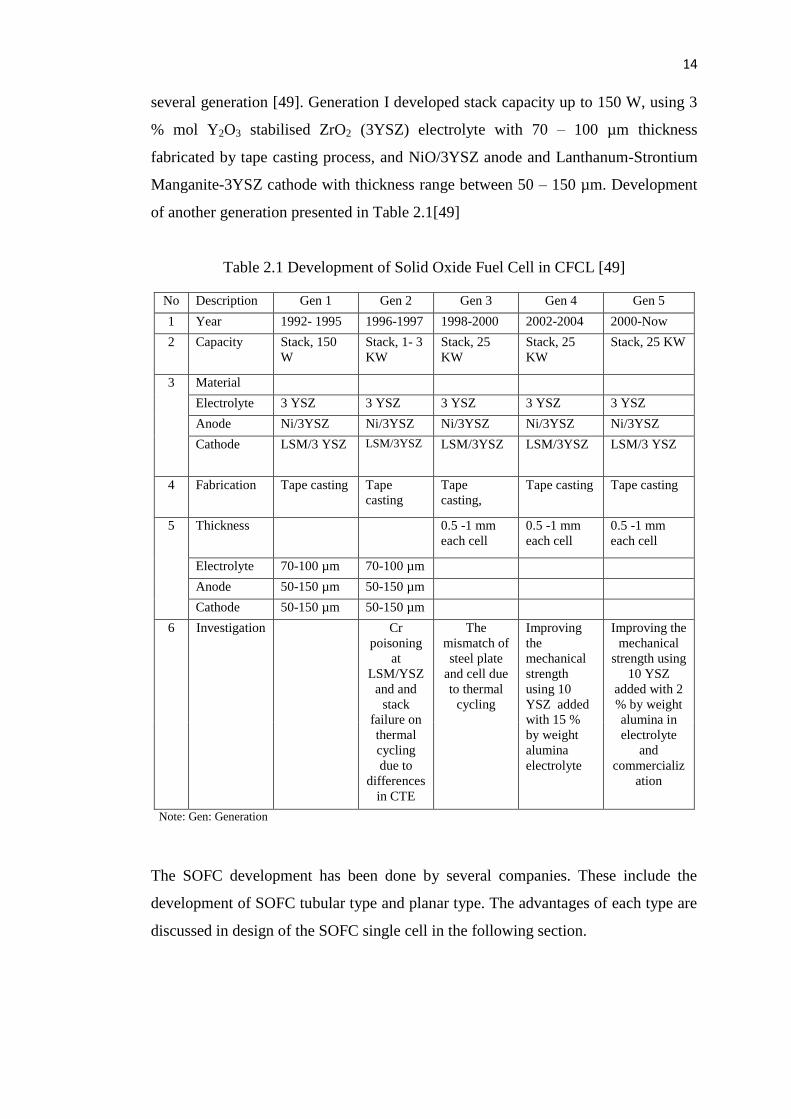
several generation [49]. Generation I developed stack capacity up to 150 W, using 3
% mol Y2O3 stabilised ZrO2 (3YSZ) electrolyte with 70 – 100 µm thickness
fabricated by tape casting process, and NiO/3YSZ anode and Lanthanum-Strontium
Manganite-3YSZ cathode with thickness range between 50 – 150 µm. Development
of another generation presented in Table 2.1[49]
Table 2.1 Development of Solid Oxide Fuel Cell in CFCL [49]
No Description Gen 1 Gen 2 Gen 3 Gen 4 Gen 5
1 Year 1992- 1995 1996-1997 1998-2000 2002-2004 2000-Now
2 Capacity Stack, 150
W
Stack, 1- 3
KW
Stack, 25
KW
Stack, 25
KW
Stack, 25 KW
3 Material
Electrolyte 3 YSZ 3 YSZ 3 YSZ 3 YSZ 3 YSZ
Anode Ni/3YSZ Ni/3YSZ Ni/3YSZ Ni/3YSZ Ni/3YSZ
Cathode LSM/3 YSZ LSM/3YSZ LSM/3YSZ LSM/3YSZ LSM/3 YSZ
4 Fabrication Tape casting Tape
casting
Tape
casting,
Tape casting Tape casting
5 Thickness 0.5 -1 mm
each cell
0.5 -1 mm
each cell
0.5 -1 mm
each cell
Electrolyte 70-100 µm 70-100 µm
Anode 50-150 µm 50-150 µm
Cathode 50-150 µm 50-150 µm
6 Investigation Cr
poisoning
at
LSM/YSZ
and and
stack
failure on
thermal
cycling
due to
differences
in CTE
The
mismatch of
steel plate
and cell due
to thermal
cycling
Improving
the
mechanical
strength
using 10
YSZ added
with 15 %
by weight
alumina
electrolyte
Improving the
mechanical
strength using
10 YSZ
added with 2
% by weight
alumina in
electrolyte
and
commercializ
ation
Note: Gen: Generation
The SOFC development has been done by several companies. These include the
development of SOFC tubular type and planar type. The advantages of each type are
discussed in design of the SOFC single cell in the following section.

15
2.5 Design of the SOFC single cell
The essential requirement in SOFC cell component is to be as thin as possible to
reduce the electrical resistance. Here, the electrical resistance is defined as the
geometric ratio of the current path length to the cross-sectional area ratio (L/A ratio)
divided by the electrical conductivity [27]. Thin SOFC cells can be produced by a
proper design selection. In general, the SOFC cell designs can be grouped into two
types; namely tubular and planar designs. The planar design can be divided into
planar anode supported-, electrolyte supported- and cathode supported SOFC [43].
The configuration of planar type solid oxide fuel is shown in Figure 2.1.
Three methods are available to fabricate membrane electrolyte assembly (MEA) of
SOFC, e.g. anode, electrolyte and cathode, supported. There exist several
disadvantages in each type of design selection [46]. For instance, the main limitation
in cathode supported design is the cathode electrode polarization, since thick cathode
prohibits oxygen diffusion [63]. Thick cathode layer will extend the path of the
movement of oxygen ions which will increase the polarization [27]. The weakness of
electrolyte supported design has a thick layer. The thick electrolyte produces high
ohmic losses due to the longer of ionic path. Additionally, the movement of ionic in
the dense electrolyte is slower than an electronic movement in the conductor. Thus,
the thick electrolyte will reduce the SOFC performance [14].
Figure 2.1: Schematic of SOFC planar, anode supported-,cathode supported-,
electrolyte supported SOFC type [43]

16
In anode supported design, the material expands relatively faster under increased
temperature which will produce internal stress. It causes internal cracks. These
cracks eventually facilitate hydrogen diffusion and higher ohmic losses [43].
Although anode-supported SOFC has a weakness, but this design is usually favoured
because of the ohmic losses is proportion to the layer thickness [27]. Some of the
companies that have developed the planar type SOFC are Siemens (USA), Sulzer
Hexis (switzerland), ECN (Energy research Centre of Nederland), TMI (Technology
Management,Inc. USA), ZTEK Corporation (USA), Fuji Electric (Japan) [62].
The advantage of planar SOFC shows the least electrical resistance because
the shortest electrical current path and the easiest for electrical current flow [64].
However, the planar type is using more seal at the peripheral cell. The seal must be
resistant at high temperature operation and compatible with adjacent components
[14]. This is the weakness that should be taken into consideration when planar type is
proposed.
The other design of SOFC is tubular type. The benefit of tubular design is
high power density and reducing seal peripheral stack [59]. The schematic of tubular
design is shown in Figure 2.2. Air and fuel air are supplied to the inside and outside,
respectively.
Figure 2.2: Schematic of tubular SOFC, showing current flow through the cell [54]
17
This design is called an Air Electrode Supported (AES), where the cathode is used to
support an electrolyte and an anode. The air as oxydant flows through inside pipe
[58]. The technology was first introduced by Siemens Westinghouse Power
Generation (SWPG), USA [64]. Several other industries that have successfully
implemented this tubular type including Mitsubishi Heavy Industry (MHI) and
Electric Power Development Company LTD (Japan), Toto and Kansai Electric
Power Company Inc., (Japan) [62].
Figure 2.2 also shows the path of electric current roughly through section of
each cell design in tubular type SOFC. In these geometries, it can be seen that the
path of electrical current can be minimized by making the pipe thin for reducing the
electrical resistance [54]. For reducing temperature operation, the geometric ratio can
be minimized by making the electrical path length as short as possible, with the cross
sectional area as large as possible [54].
Despite the advantages possessed by tubular type, the major concern in
tubular design is its high production cost [64]. The lengthy current path in the tube
caused higher area specific resistance (ASR). Higher ASR will impede for electrical
current flow which subsequently reduce the SOFC performance [27].
In summary, the selection of design type depends on the manufacturing cost
and ease to create a thin cell. For the lab scale, a planar type is most preferable [19,
65, 66]. Apart from the geometry, the material used for sample is of interest as it
affects the performance of the SOFC. Next section will highlight the material used
for SOFC in more details.
2.6 SOFC material selection
A single cell of SOFC comprised of a porous electrode, i.e. anode, cathode and solid
electrolyte. Material selections for the anode, electrolyte and cathode are carefully
evaluated in order to acquire the maximum potential of SOFC. Also discussed is the
formation of porous materials which require additional material called pore former.

18
2.6.1 Anode material
The main function of anode is to promote the electrochemical oxidation of fuel [67].
The fuel in the form of hydrogen gas will be converted into positively charged
hydrogen ion and negatively charged electron [43]. The chemical and
electrochemical processes often occur preferentially at certain surface and interfacial
sites or triple-phase boundary (TPB) [29]. The general requirements of anode
material include [29, 67] :
1. Good thermal and chemical stability during fuel cell operation and
fabrication.
2. Excellent catalytic activity towards the oxidation of fuels
3. Manageable mismatch in coefficient of thermal expansion (CTE) with
adjacent cell components
4. Sufficient mechanical strength and flexibility
5. Ease of fabrication and low cost.
6. Good electronic conductivity.
Several materials can be used as anode, i.e. graphite, platinum, iron, cobalt and
nickel [68]. The most preferable material for anode was Nickel (Ni) due to its low
cost, excellent catalytic activity toward hydrogen oxidation and good chemical
stability [69]. However, pure nickel suffers from considerable mismatch in thermal
expansion with YSZ (yttria stabilized zirconia), coarsening during operation and
poor binding with YSZ electrolyte [68]. The characteristics possessed by pure nickel
were not good for anode materials. Nevertheless, nickel oxide (NiO) has
demonstrated the other way, which shows compatibility with YSZ.
The material NiO/YSZ anode was first innovated by Spacil [70] in
accordance with YSZ electrolyte. Development of NiO/YSZ cermet (ceramic
metallic composite) anode is compatible for YSZ electrolyte due to both CTE were
almost same [14]. In a porous NiO/YSZ cermet anode, the Ni metal phase provides
the required electronic conductivity and catalytic activity, whereas the YSZ ceramic
phase lowers the coefficient of thermal expansion of anode to match the YSZ
electrolyte. Also the YSZ can prevent the Ni phase from coarsening [68].
In this research anode material used NiO/YSZ with composition of 60 wt. %
NiO and 40 wt. % YSZ. This anode material has a coefficient of thermal expansion
of 12.6 x10⁻⁶
/K [71] and has electrical conductivity of 700 S/cm [68] at temperature

19
of 1000 ○C. The NiO-YSZ material was selected as anode material because of
inexpensive and the CTE compatibility with YSZ electrolyte.
2.6.2 Electrolyte material
The main function of electrolyte is as ionic conductor especially oxygen ion. The
current flow occurs by movement of oxygen ions through the crystal lattice [72]. The
ion movement is a result of thermally activated hopping of the oxygen ion, moving
from one crystal lattice site to its neighbour site [27].
The general requirements of SOFC electrolyte material include [14, 54, 73]:
1. Electronically insulating
2. Chemically stable at high temperature
3. Gas tight/free pores
4. Coefficient of thermal expansion (CTE) matches with electrode
5. Inexpensive material
6. Sufficient mechanical strength and flexibility
7. Negligible interaction with electrode materials under operation and
fabrication.
Several materials can be used as electrolyte, i.e. Yttria Stabilized Zirconia (YSZ),
Scandia Stabilized Zirconia (ScSZ), Calcium Stabilized Zirconia (CaSZ), Samarium
doped Ceria (SDC) [14], Samarium doped Ceria Carbonate (SDCC) [8]. The YSZ
material is usually chosen as electrolyte material due to its low cost, electronically
insulating, good chemical stability at higher temperature and appropriate CTE with
NiO/YSZ anode material [73]. The dopants of Yttria (Y2O3) are added to create
oxygen vacancies in the lattice site zirconia (ZrO2) [72]. The oxygen vacancy is
considered as the path of oxygen ion conduction in the stabilized zirconia [27].
In this research, yttria stabilized zirconia 8 mol% (8YSZ) was used as
electrolyte material. This material has a coefficient of thermal expansion 10 x 10-6
/K
[71] and has electrical conductivity of 6.62 x 10⁻²
S/cm [12] at temperature of
1000○C. The 8YSZ material was selected as electrolyte material because of
inexpensive and the CTE compatibility with NiO-YSZ anode.

20
2.6.3 Cathode material
The primary function of cathode is to promote electrochemical reduction of oxidant
such as oxygen or air. The oxygen gas and electron were converted into oxygen ion
[74]. The electrochemical processes often occur preferentially at certain surface and
interfacial sites or triple-phase boundary (TPB) [75].
The general requirements of SOFC cathode material include [14, 74]:
1. Chemically compatible with electrolyte material
2. High electronic conductivity
3. Catalyse the dissociation of oxygen
4. Adhesion to electrolyte surface
5. Relatively inexpensive materials
6. High ionic conductivity
7. Stable in an oxidizing environment
8. Thermal expansion coefficient similar to the other SOFC materials
Several materials can be used as cathode, i.e. LSF (La0.8Sr0.2FeO3), LSC
(La0.8Sr0.2CoO3), LSAF (La0.8Sr0.2Al0.2Fe0.8O3), LSM/YSZ (La0.8Sr0.2MnO3-YSZ)
[14, 74], LSCF/SDCC (Lanthanum Strontium Cobalt Ferrite- Samarium Doped Ceria
Carbonate) [8]. The LSM/YSZ was chosen as cathode material due to its low cost,
electronically insulating, good chemical stability at higher temperature and
appropriate CTE with YSZ electrolyte material. It also has high ionic conductivity
[14].
In this research, the cathode material was LSM/YSZ. This material has a
coefficient of thermal expansion of 11.2 x 10⁻⁶
/K [76] and oxygen ionic conductivity
of 3 x 10⁻³
S/cm [74] at temperature of 1000○C. The LSM/YSZ material was selected
as cathode material because it is inexpensive, has high oxygen ionic conductivity and
the CTE compatibility with YSZ electrolyte.
2.6.4 Pore former material
Porosity is necessary for anode and cathode to facilitate the gas transportation [54].
Therefore, it is important for anode and cathode to have substantial pores to allow the
process. The porosity of the anode and cathode can be controlled with the addition of

21
pore former into the matrix [77]. The porous material include potato, wheat, tapioca,
corn and rice [78]. The properties of starch is shown in Table 2.2, with the
percentage by weight of amylose content, amylopectin content and gelatinization
temperature of starch [78].
Table 2.2 : Properties of starch as pore former [78]
No Starch
type
Amylose content
(%) wt.
Amylopectin content
(%) wt.
Gelatinization
(○ C)
1 Potato 20-21 79-80 50-56
2 Wheat 25-30 70-75 58
3 Tapioca 16-17 83-84 49
4 Corn 25-28 72-75 62
5 Rice 17-30 70-83 58-69
The contents of amylose, amylopectin and temperature gelatinization of potato are
20-21 % wt., 79-80 % wt. and 50-56 ○C, respectively. Content of amylose,
amylopectin and temperature gelatinization in the cornstarch are 25-28 wt%, 72-75
wt% and 62○C respectively. These amylose and amylopectin molecule can be
functioned as binder in ceramic [78, 79]. The five types of starch (Table 2.2) are
frequently used in the ceramics industry as the pore former [78].
The evaluation of corn-starch decomposition was performed using TGA
(Thermogravimetric Analyzer). The weight change of corn-starch during the heating
process can be illustrated in Figure 2.3.
Figure 2.3: Thermal decomposition of corn-starch using TGA with different moisture
content (%) heated at 5○C/min: (a) 0: (b) 6.91; (c) 13.55; (d) 20.12; (e) 34.92; (f)
50.67 [80].

22
The heating rate is 5○C/min and the corn-starch contains different moisture. TGA
studies were used to analyse the kinetic decomposition of corn-starch [80]. At
temperature range of 280 ○C to 325
○C, powder mass is changing rapidly, indicated
by lines dropped sharply. Then at a temperature of 325 ○C to 500
○C, the mass
changes slowly, indicated by the sloping lines and at a temperature of about 550 ○C
all the starch burned out [81]. The results of the analysis using TGA is used to help
sintering process stage in the manufacturing of a porous disc [82]. Although corn-
starch contain varying moisture content (Figure 2.3), the corn-starch was burnt out at
a temperature of 550 ○C [81].
In this research the selected pore former material is cornstarch. This
material can form hydrogen bonding with material anode and cathode as it contains
higher amylopectin and amylose of 25 wt% and 75 wt% respectively. The cornstarch
has the highest gelatinization temperature than the others except with rice starch and
it is cheaper than rice starch. The gelatinization temperature affects the
agglomeration of the powder. The lower gelatinization temperature of starch is ease
to agglomerate the ceramic powder during mixing process [78]. The material can be
burnt out at temperature 600○C that will be easy to escape from matrix to form pore
[82]. The material also was inexpensive.
2.7 Production of SOFC
SOFC performance can be affected by several factors. These factors include material
that has specific electrical conductivity, thickness of each component cell and
processes [54]. The electrical conductivity material should be selected with highest
conductivity at certain temperature operation [67]. The processes affect the quality of
SOFC components such as microstructure, crack, homogeneous pore, delamination
and three phase boundary (TPB) [29].
Requirement of membrane solid oxide fuel cell is as thin as possible to reduce
the path of the moving electron or ions. The short path of moving electron will
reduce the ohmic losses [54]. Several companies such as Rolls- Royce (UK) [61],
CFCL (AUS) [49] have manufactured an anode-supported SOFC with the thickness
between 100-1500 µm and the electrolyte thickness of 2–300 µm [62].

23
The relationship between the thickness and the electrical resistance is very close. The
relationship is expressed by the following mathematical Equation 2.1 [27].
(2.1)
where R is resistance (ohm), t is thickness of material (m), A is cross- sectional area
(m2), σ is conductivity (Siemens/m), and Siemens is 1/ohm.
From Equation 2.1 it can be seen that the resistance depends on geometry of the
substrate. The specimen thickness is reduced when the electrical resistance is
reduced. The electrical resistance also can be reduced by expanding cross-sectional
area [54].
Several methods have been developed to obtain a relatively thin cell SOFC.
The consolidation process of these cells can be done by conventional methods or
non-conventional methods [14]. The conventional methods are divided into the dry
method or wet ceramics method. The dry consolidation method is dry compaction,
while the wet ceramic methods include tape casting, spin coating and spraying [22].
The non-conventional methods include Electrochemical Vapour Deposition (EVD),
Chemical Vapour Deposition (CVD) and physical vapour deposition (PVD) [62].
The weakness of the conventional process is that the product was still required
sintering process to improve its strength, while the advantages the process is
inexpensive and simple. The non-conventional weakness is that the process is
difficult, complicated and expensive processes, while the advantages of non-
conventional process is a thin layer does not require a sintering process [83].
Another factor affecting the performance of SOFC is the microstructure
either in the electrode and electrolyte [24]. The microstructure can affect strength of
the cell component, where the dense electrolyte and without pores produce a good
SOFC performance [83]. The microstructure can be improved by early treatment
through a ball mill [84] or ultrasonic [85] processes to obtain the small powder grain
size before the consolidation process. The microstructure is also affected by the
sintering process. The small grain size and controlled sintering process can produce a
uniform microstructure [82]. The controlled sintering process can produce dense
structures in the electrolyte layer so that it can improve the performance of SOFC
[83].

24
In this research, a compaction method was used for manufacturing an anode-
supported SOFC, while an electrolyte and a cathode layers were done by wet powder
spraying (WPS) method. The air sintering was performed to increase strength of the
green compact anode, electrolyte and cathode layers. In order to improve the quality
of microstructure and homogeneous pore at the anode, a mixture of powder and pore
formers were processed either by the ball mill or ultrasonic. The compaction and
WPS methods are chosen due to the uncomplicated processes, simple and
inexpensive equipment, while the air sintering method was easy to do and
uncomplicated.
2.7.1 Powder process
Anode-supported SOFC requires pores estimated for about 20-60 vol% [14]. The
manipulation of the porous anode can be controlled by addition of pore former [77].
The distribution and size pore should be homogeneous to improve SOFC
performance. The size and distribution can be performed by ball mill [8] and
ultrasonic [85] process.
2.7.1.1 Ball mill process
Ball mill (BM) process can be used to reduce the particle size. Particle size can affect
the microstructure of the material. At the anode, the particle size can influence the
TPB (three phase boundary) which located in the interface of anode-electrolyte. The
three-phase boundary (TPB) is the site that the electrochemical reaction occurs. The
TPB can be improved by reducing the particle size [29].
Principally, the ball mill reduce particle size by using collision [86]. The ball
mill (BM) can produce powder from 1 mm to nano size particles [86]. The types of
mill that have been used include high compression roller mills, jet mills and ball
mills. Ball mills are categorized into several types, depending on the method used to
set the ball movement [84, 86]. The mechanical energy was supplied to the particles
to create a new surface [86]. The physical properties of particles change such as
elastic deformation, increase in temperature, and the rearrangement of the lattice

132
REFERENCES
1. Haroune Aouzellag, Kaci Ghedamsi, Djamel Aouzellag, Review, Energy
Management and Fault Tolerant Control Strategies for Fuel Cell/Ultra-
Capacitor Hybrid Electric Vehicles to Enhance Autonomy, Efficiency and
Life Time of the Fuel Cell System. International Journal of Hydrogen
Energy, 2015. 40: p. 7204-7213.
2. Puqing Yang, Ying Zhu, Pei Zhang, Houcheng Zhang, Ziyang Hu, Jinjie
Zhang Performance Evaluation of an Alkaline Fuel Cell/Thermoelectric
Generator Hybrid System. International Journal of Hydrogen Energy 2014.
39: p. 11756-11762.
3. Xiuqin Zhang, Huiying Liu, Meng Ni, Jincan Chen, Performance Evaluation
and Parametric Optimum Design of a Syngas Molten Carbonate Fuel Cell and
Gas Turbine Hybrid System. Renewable Energy 2015. 80: p. 407-414.
4. Younes Ansari, Telpriore G. Tucker, C. Austen Angell, Short
communication, A novel, Easily Synthesized, Anhydrous Derivative of
Phosphoric Acid for Use in Electrolyte with Phosphoric Acid-Based Fuel
Cells. Journal of Power Sources, 2013. 237: p. 47-51.
5. Behzad Najafi, Alireza Haghighat Mamaghani, Fabio Rinaldi, Andrea
Casalegno, Long-Term Performance Analysis of an HT-PEM Fuel Cell
Based Micro-CHP System: Operational Strategies. Applied Energy, 2015.
147: p. 582-592.
6. Tan Zhongfu, Zhang Chen, Liu Pingkuo, Brent Reed, Zhao Jiayao, Focus on
Fuel Cell Systems in China. Renewable and Sustainable Energy Reviews
2015. 47: p. 912-923.
7. Hasan Ozcan, Ibrahim Dincer, Performance Evaluation of an SOFC Based
Trigeneration System Using Various Gaseous Fuels From Biomass
Gasification. International Journal of Hydrogen Energy, 2015. 40: p. 7798-
7807.
133
8. Hamimah Abd. Rahman, Andanastuti Muchtar, Norhamidi Muhamad, Huda
Abdullah LSCF6428-SDC carbonate composite cathodes for low-temperature
solid oxide fuel cells. Materials Chemistry and Physics, 2013. 141: p. 752-
757.
9. Muhammed Ali S.A, Andanastuti Muchtar, Abu Bakar Sulonga, Norhamidi
Muhamada, Edy Herianto Majlan, Influence of Sintering Temperature on the
Power Density of Samarium-Doped-Ceria Carbonate Electrolyte Composites
for Low-Temperature Solid Oxide Fuel Cells. Ceramics International 2013.
39: p. 5813-5820.
10. Lan Zhang, San Ping Jiang, Wei Wang, Yujun Zhang, Short Communication
NiO/YSZ, Anode-Supported, Thin-Electrolyte, Solid Oxide Fuel Cells
Fabricated by Gel Casting. Journal of Power Sources 2007. 170: p. 55-60.
11. Jianbing Huang, Fucheng Xie, Cheng Wang, Zongqiang Mao, Development
of Solid Oxide Fuel Cell Materials for Intermediate-to-Low Temperature
Operation. International Journal of Hydrogen Energy, 2012. 37: p. 877-883.
12. Chih-Chung T. Yang, Wen-Cheng J. Wei, Andreas Roosen, Electrical
Conductivity and Microstructures of La0.65Sr0.3MnO3-δ mol%-Yttria-
Stabilized Zirconia. Materials Chemistry and Physics 2003. 81: p. 134-142.
13. Xiuxia Meng, Xun Gong, Naitao Yang, Xiaoyao Tan, Yimei Yin, Zi-Feng
Ma, Fabrication of Y2O3-Stabilized-ZrO2(YSZ)/La0.8Sr0.2MnO3-δ/YSZ Dual-
Layer Hollow Fibers for the Cathode-Supported Micro-Tubular Solid Oxide
Fuel Cells by a Cospinning/co-Sintering Technique. Journal of Power
Sources, 2013. 237: p. 277-284.
14. Keegan C. Wincewicz, Joyce S. Cooper, Taxonomies of SOFC material and
manufacturing alternatives. Journal of Power Sources, 2005. 140: p. 280-296.
15. Ji-Won Son, Ho-Sung Noh, Hae-Weon Lee, Jong Ho Lee, Hae-Ryoung Kim,
Jong Cheol Kim, Anode-Supported Solid Oxide Fuel Cell Comprising a
Nanoporous layer Having a Pore Gradient Structure, and a Production
Methode Therefor, in US Patent 2012, 2012/0003565A1: USA. p. 1-10.
16. Stupkiewicz S., A. Piccolroaz, D. Bigoni, Elastoplastic Coupling to Model
Cold Ceramic Powder Compaction. Journal of the European Ceramic
Society, 2014. 34: p. 2839–2848.
17. Daniel Storjohann, James Daggett, Neal P. Sullivan, Huayang Zhu, Robert J.
Kee, Sophie Menzer, Dustin Beeaff, Fabrication and evaluation of solid-

134
oxide fuel cell anodes employing reaction-sintered yttria-stabilized zirconia.
Journal of Power Sources 2009. 193: p. 706–712.
18. Mohadeseh Seyednezhad, Armin Rajabi, Andanastuti Muchtar, Mahendra
Rao Somalu, Characterization of IT-SOFC Non-Symmetrical Anode Sintered
through Conventional Furnace and Microwave. Ceramics International,
2015. 41: p. 5663–5669.
19. Kongfa Chen, Zhe L¨u, Na Ai, Xiangjun Chen, Xiqiang Huang, Wenhui Su,
Experimental study on effect of compaction pressure on performance of
SOFC anodes. Journal of Power Sources 2008. 180: p. 301–308.
20. Peng Chen, Gap-Yong Kim, Jun Ni, Investigations in the Compaction and
Sintering of Large Ceramic Parts. Journal of Materials Processing
Technology 2007. 190: p. 243-250.
21. German, R.M., Powder Metallurgy of Iron and Steel 1998, New York, USA:
John Wiley & Sons, Inc.
22. Rahaman, M.N., Ceramic Processing 2007, Boca Raton, Florida, USA: CRC
Press Taylor & Francis Group.
23. Zhenwei Wang, Mojie Cheng, Yonglai Dong, Min Zhang, Huamin Zhang,
Anode-supported SOFC with 1Ce10ScZr modified cathode/electrolyte
interface. Journal of Power Sources, 2006. 156: p. 306-310.
24. Barsoum, M., Materials Science and Engineering Series, Fundamentals of
Ceramics1997, United States of America: McGraw-Hill Companies.
25. Pizette P., C.L. Martin, G. Delette, P. Sornay, F. Sans, Compaction of
Aggregated Ceramic Powders: From Contact Laws to Fracture and Yield
Surfaces. Powder Technology 2010. 198: p. 240-250.
26. Shiqiang (Rob) Hui, Justin Roller, Sing Yick, Xinge Zhang, Cyrille Deces-
Petit, Yongsong Xie, Radenka Maric, Dave Ghosh, Review, A brief Review
of the Ionic Conductivity Enhancement for Selected Oxide Electrolytes.
Journal of Power Sources, 2007. 172: p. 493-502.
27. Ryan P. O'Hayre, Suk-Won Cha, Whitney Colella, Fritz B. Prinz, Fuel Cell
Fundamentals, 2006, United State of America: John Wiley & Sons, Inc.
28. Shinagawa, K., Simulation of Grain Growth and Sintering Process by
Combined Phase-Field/Discrete-Element Method. Acta Materialia 2014. 66:
p. 360-369.

135
29. Chunwen Sun, U.S., Review Recent Anode Advances in Solid Oxide Fuel
Cells. Journal of Power Sources, 2007. 171: p. 247-260.
30. Claire Ferchaud, Jean-Claude Grenier, Ye Zhang-Steenwinkel, Marc M. A.
van Tuel, Frans P. F. van Berkel, Jean-Marc Bassat, High performance
praseodymium nickelate oxide cathode for low temperature solid oxide fuel
cell. Journal of Power Sources, 2011. 196(4): p. 1872-1879.
31. Daniel C. Andersson, Per-Lennart Larsson, Alessandro Cadario, Per
Lindskog, On the Influence from Punch Geometry on the Stress Distribution
at Powder Compaction. Powder Technology 2010. 202: p. 78-88.
32. IEA, Energy Technology Perspectives 2008,Scenarios and Strategies to 2050,
2008: Paris, France.
33. IEA, IEA Statistic CO2 Emission from Fuel Combustion Highlights, 2010:
Paris, France.
34. Shahriar Shafiee, Erkan Topal, When will Fossil Fuel Reserves be
Diminished? Energy Policy, 2009. 37: p. 181-189.
35. Shahriar Shafiee, Erkan Topal, A Long-term view of Worldwide Fossil Fuel
Prices. Applied Energy, 2010. 87: p. 988 - 1000.
36. Yue-Jun Zhang, Zi-Yi Wang, Investigating the Price Discovery and Risk
Transfer Functions in the Crude Oil and Gasoline Futures Markets: Some
Empirical Evidence. Applied Energy 2013. 104: p. 220-228.
37. Zegers, P., Fuel cell commercialization : The key to a Hydrogen Economy.
Journal of Power Sources, 2006. 154: p. 497-502.
38. Hanne Lerche Raadal, Bjørn Ivar Vold, Anders Myhr, Tor Anders Nygaard,
GHG (Green Hous Gases) Emissions and Energy Performance of Offshore
Wind Power. Renewable Energy 2014. 66: p. 314-324.
39. Juergen H. Peterseim, Stuart White, Amir Tadros, Udo Hellwig, Review
Concentrated Solar Power Hybrid Plants, which Technologies are Best Suited
for Hybridisation? Renewable Energy 2013. 57: p. 520-532.
40. Johnstone C.M., D. Pratt, J.A. Clarke, A.D. Grant, A Techno-Economic
Analysis of Tidal Energy Technology. Renewable Energy 2013. 49: p. 101-
106.
41. Kevin Huang, John B Goodenough, Solid Oxide Fuel Cell Technology
Principles, Performance and Operations 2009, Great Abington, Cambridge,
UK: Woodhead Publishing Limited and CRC Press LLC.
136
42. Xiongwen Zhang, S.H. Chan, Guojun Li, H.K. Ho, Jun Li, Zhenping Feng, A
review of Integration Strategies for Solid Oxide Fuel Cells. Journal of Power
Sources, 2010. 195: p. 685–702.
43. Matthew, M.M., Fuel Cell Engine 2008, Hoboken, New Jersey, USA: John
Wiley & Sons.
44. Timothy E. Lipman, Jennifer L. Edwards, Daniel M. Kammen, Fuel Cell
System Economics: Comparing the Costs of Generating Power with
Stationary and Motor Vehicle PEM Fuel Cell Systems. Energy Policy, 2004.
32: p. 101-125.
45. Li, X., Principles of Fuel Cells 2006, Madison Avenue, New York, USA:
Taylor & Francis Group.
46. Gasik, M., Materials for Fuel Cells 2008, Cambridge England: Woodhead
Publishing Limied.
47. Spiegel, C., Designing and Building Fuel Cell 2007, United State of America:
McGraw-Hill Company.
48. Society, T.A.C., Progress in Solid oxide Fuel Cells 2006, Hoboken, New
Jersey, USA: John Wiley & Sons, Inc.
49. K. Foger, J.G. Love, Fifteen years of SOFC development in Australia. Solid
State Ionic, 2004. 174: p. 119-126.
50. Hwang, J.-J., Transient Efficiency Measurement of a Combined Heat and
Power Fuel Cell Generator. Journal of Power Sources 2013. 223: p. 325-335.
51. Shaolin Ma, Jiangfeng Wang, Zhequan Yan, Yiping Dai, Bingheng Lu,
Thermodynamic Analysis of a New Combined Cooling, Heat and Power
System Driven by Solid Oxide Fuel Cell Based on Ammonia–Water Mixture.
Journal of Power Sources, 2011. 196: p. 8463– 8471.
52. Lúcia Bollini Braga, Jose Luz Silveira, Marcio Evaristo da Silva, Einara
Blanco Machin, Daniel Travieso Pedroso, Celso Eduardo Tuna, Comparative
Analysis Between a PEM Fuel Cell and an Internal Combustion Engine
Driving an Electricity Generator: Technical, Economical and Ecological
Aspects. Applied Thermal Engineering, 2014. 63: p. 354-361.
53. G. Cacciola, V. Antonucci, S. Freni, Technology Up Date and New Strategies
on Fuel Cells. Journal of Power Sources, 2001. 100: p. 67-79.

137
54. Wolf Vielstich, Harumi Yokokawa, Hubert A Gasteiger, Handbook of Fuel
Cells Fundamentals Technology and Applications 2009, Chichester, West
Sussex, United Kingdom: John Wiley & Sons.
55. Andrzej Wieckowski, Jens K. Norskov, Fuel Cell Science Theory,
Fundamentals and Biocatalysis 2010, Hoboken, New Jersey, USA: John
Wiley & Sons.
56. Bernd Emonts, Ludger Blum, Thomas Crube, Werner Lehnert, Jurgen
Mergel, Martin Muller and Ralf Peters, Technical Advancement of Fuel-Cell
Research and Development in Fuel Cell Science and Engineering Materials,
Processes, Systems and Technology. Vol. 1. 2012, Weinheim, Germany:
Wiley-VCH Verlag GmbH & Co. KGaA.
57. Laguna-Bercero, M.A., Review Recent Advances in High Temperature
Electrolysis Using Solid Oxide Fuel Cells: A Review. Journal of Power
Sources 2012. 203: p. 4– 16.
58. Hoogers, G., Fuel Cell Technology Hand Book 2003, Denver, MA, USA:
CRC Press LLC.
59. M.C. Williams, J.P. Strakey, Subhash C. Singhal, U.S Distributed Generation
Fuel Cell Program. Journal of Power Sources, 2004. 131: p. 79-85.
60. Boudghene Stambouli A., E.Traversa, Solid oxide fuel cells (SOFCs): A
Review of an Environmentally Clean and Efficient Source of Energy.
Renewable & Sustainable Energy Reviews, 2002. 6: p. 433 - 455.
61. Gardner F.J., M.J. Day, N.P. Brandon, M.N. Pashley, M. Cassidy, SOFC
Technology Development at Rolls-Royce. Journal of Power Sources, 2000.
86: p. 122-129.
62. Tietz F., H.-P. Buchkremer, D. Stover, Review Article Components
Manufacturing for Solid Oxide Fuel Cells. Solid State Ionic, 2002. 152-153:
p. 373-381.
63. Selmar de Souza, Steven J. Visco, Lutgard C. De Jonghe, Thin Film Solid
Oxide Fuel Cell with High Performance at Low-Temperature. Solid State
Ionic, 1997. 98: p. 57-61.
64. Singal, S.C., Advances in solid oxide fuel cell technology. Solid State Ionic,
2000. 135: p. 305-313.
65. Han Chen, Kui Cheng, Zhicheng Wang, Wenjian Weng , Ge Shen, Piyi Du
and Gaorong Han, Preparation of Porous NiO-Ce0.8Sm0.2O1.9 Ceramics for

138
Anode-supported Low-temperature Solid Oxide Fuel Cells. Journal Material
Science Technology 2010. 26 (6): p. 523-528.
66. Laxmidhar Besra, Shaowu Zha, Meilin Liu, Preparation of NiO-YSZ/YSZ
Bi-layers for Solid Oxide Fuel Cells by Electrophoretic Deposition. Journal
of Power Sources 2006. 160: p. 207–214.
67. Fergus, J.W., Oxide Anode Materials for Solid Oxide Fuel Cells. Solid State
Ionic, 2006. 177: p. 1529-1541.
68. Zhe Cheng, Jeng-Han Wang, and Meilin Liu, Anodes,in Jeffrey W. Fergus
(Ed.)Green Chemistry and Chemical Engineering Solid Oxide Fuel Cells
Materials Properties and Performance 2009, Boca Raton, USA: CRC Press
Taylor & Francis Group.
69. John B. Goodenough, Yun-Hui Huang, Review Alternative Anode Materials
for Solid Oxide Fuel Cells. Journal of Power Sources, 2007. 173: p. 1-10.
70. Spacil, H.S., Electrical Device Including Nickel- Containing Stabilized
Zirconia Electrode, in United States Patent Office 1970, 3503809: USA. p. 1-
8.
71. Janine Johnson, Jianmin Qu, Effective Modulus and Coefficient of Thermal
Expansion of Ni–YSZ Porous Cermets. Journal of Power Sources 2008. 181:
p. 85-92.
72. Xia, C., Electrolyte, in Jeffrey W. Fergus (Ed.)Green Chemistry and
Chemical Engineering Solid Oxide Fuel Cells Materials Properties and
Performance 2009, Boca Raton, Florida, USA: CRC Press Taylor & Francis
Group.
73. Fergus, J.W., Electrolyte for Solid Oxide Fuel Cells. Journal of Power
Sources, 2006. 162: p. 30-40.
74. San Ping Jiang and Jian Li, Cathodes, in Jeffrey W. Fergus (Ed.)Green
Chemistry and Chemical Engineering Solid Oxide Fuel Cells Materials
Properties and Performance 2009, Boca Raton, Florida, USA: CRC Press
Taylor & Francis Group.
75. Adler, S.B., Factors Governing Oxygen Reduction in Solid Oxide Fuel Cell
Cathodes. Chemical Reviews, American Chemical Society, 2004. 104: p.
4791-4843.
76. Arata Nakajo, Jakob Kuebler, Antonin Faes, Ulrich F. Vogt, Hans Ju¨rgen
Schindler, Lieh-Kwang Chiang, Stefano Modena, Jan Van herle, Thomas

139
Hocker, Compilation of Mechanical Properties for The Structural Analysis of
Solid Oxide Fuel Cell Stacks. Constitutive Materials of Anode-Supported
Cells. Ceramics International 2012. 38: p. 3907–3927.
77. Rym Dhouib Sahnoun, Semia Baklouti, Characterization of Flat Ceramic
Membrane Supports Prepared with Kaolin-Phosphoric Acid-Starch. Applied
Clay Science 2013. 83-84: p. 399-404.
78. Eva Gregorov´a , Willi Pabst, Ivan Bohaˇcenko, Characterization of Different
Starch Types for Their Application in Ceramic Processing. Journal of the
European Ceramic Society 2006. 26: p. 1301-1309.
79. Kategunya Rengsutthi, Sanguansri Charoenrein, Physico-Chemical Properties
of Jackfruit Seed Starch (Artocarpus Heterophyllus) and Its Application as a
Thickener and Stabilizer in Chilli Sauce. LWT - Food Science and
Technology, 2011. 44: p. 1309-1313.
80. Gilles Taillades, Pierre Batocchi, Abdel Essoumhi, Mélanie Taillades,
Deborah J. Jones, Jacques Rozière, Engineering of Porosity, Microstructure
and Electrical Properties of Ni–BaCe0.9Y0.1O2.9 Cermet Fuel Cell Electrodes
by Gelled Starch Porogen Processing. Microporous and Mesoporous
Materials 2011. 145: p. 26–31.
81. Hongsheng Liu, Fengwei Xie, Long Yu, Ling Chen, Lin Li, Thermal
Processing of Starch-Based Polymers. Progress in Polymer Science, 2009 34:
p. 1348–1368.
82. Rahaman, M.N., Sintering of Ceramics 2008, Boca raton, Florida, USA: CRC
Press Taylor & Francis Group.
83. Olivera Kesler and Paolo Marcazzan, Processing, in Jeffrey W. Fergus (Ed.)
Green Chemistry and Chemical Engineering Solid Oxide Fuel Cells Materials
Properties and Performance 2009, Boca raton, Florida, USA: CRS Press
Taylor & Francis Group.
84. C.Suryanarayana, Mechanical Alloying and Milling. Progress in Materials
Science, 2001. 46: p. 1-184.
85. Timothy J. Mason and John P. Lorimer, Applied Sonochemistry, The Uses of
Power Ultrasound in Chemistry and processing 2002, Weinheim, Germany:
Wiley-VCH Verlag GmbH.

140
86. Masrom, A.K., Workshop on Mechanical Milling for Production of
Nanostructured Materials from Nanoparticles to Nanotubes, December, 2009:
Amrec, Sirim Berhad, Malaysia. p. 1-127.
87. Alain Bourdillon, Giovanni Occhipinti, Jean-Philippe Molinié, Véronique
Rannou, HF Radar Detection of Infrasonic Waves Generated in the
Ionosphere by the 28 March 2005 Sumatra Earthquake. Journal of
Atmospheric and Solar-Terrestrial Physics 2014. 109: p. 75-79.
88. Yi Han, Huayan Sun, Huichao Guo, Analysis of Influential Factors on a
Space Target's Laser Radar Cross-section. Optics & Laser Technology, 2014.
56: p. 151-157.
89. Rubens L.Oliveira, Beatriz S.L.P. de Lima, Nelson F.F.Ebecken, Multiway
Analysis in Data SONAR Classification. Mechanical Systems and Signal
Processing 2014: p. 531-541.
90. Bruce W. Drinkwater, Paul D. Wilcox, Ultrasonic Arrays for Non-
Destructive Evaluation: A Review. NDT&E International 2006. 39: p. 525-
541.
91. Garcia P., B Ferrari, R. Moreno, A.J. Sanches-Herencia, M.T. Colomer,
YSZ/Ni–YSZ Semi-cells Shaped by Electrophoretic Deposition. Journal of
the European Ceramic Society, 2007. 27: p. 4241-4244.
92. Shigeyuki Somiya and Tokuji Akiba, Hydrothermal Zirconia Powders: A
Bibliography. Journal of the European Ceramic Society 1999. 19: p. 81- 87.
93. Oleg Vasylkiva, Yoshio Sakka, Yasuaki Maeda , Valeriy V. Skorokhod,
Nano-engineering of Zirconia–noble Metals Composites. Journal of the
European Ceramic Society 2004. 24: p. 469–473.
94. P´erez-Rodr´ıguez J.L., J. Pascual, F. Franco, M.C. Jim´enez de Haro, A.
Duran, V. Ram´ırez del Valle, L.A. P´erez-Maqueda, The influence of
Ultrasound on the Thermal Behaviour of Clay Minerals. Journal of the
European Ceramic Society 747–753, 2006. 26: p. 747–753
95. Luis A. Pe´rez-Maqueda, Jose´ M. Blanes, Jose´ Pascual, Jose´ L. Pe´rez-
Rodrı´guez, The Influence of Sonication on the Thermal Behavior of
Muscovite and Biotite. Journal of the European Ceramic Society 2004. 24:
p. 2793–2801.
96. Lars Rose, Olivera Kesler, Zhaolin Tang, Alan Burgess, Application of Sol
gel Spin Coated Yttria-Stabilized Zirconia Layers for the Improvement of

141
Solid Oxide Fuel Cell Electrolytes Produced by Atmospheric Plasma
Spraying. Journal of Power Sources 2007. 167: p. 340–348.
97. Schrijnemakers A., S. André, G. Lumay, N. Vandewalle, F. Boschini, R.
Cloots, B. Vertruyen, Mullite Coatings on Ceramic Substrates: Stabilisation
of Al2O3–SiO2 Suspensions for Spray Drying of Composite Granules Suitable
for Reactive Plasma Spraying. Journal of the European Ceramic Society
2009. 29 p. 2169–2175.
98. Maciej Wozniak, Yoram de Hazan, Thomas Graule, Dariusz Kata, Rheology
of UV Curable Colloidal Silica Dispersions for Rapid Prototyping
Applications. Journal of the European Ceramic Society 2011. 31 p. 2221–
2229.
99. Ferguson, B.L., Powder Shaping and Consolidation Technologies in ,Powder
Metal Technologies and Applications. Vol. 7. 1999, San Fransisco, USA:
ASM International
100. Reed, J.S., Principles of Ceramics Processing 1995, New York, USA: John
Wiley & Sons, Inc.
101. Kennedy T., S. Hampshire & Y. Yaginuma, A Study of the Compaction
Mechanism of Granulated Materials. Journal of the European Ceramic
Society, 1997. 17: p. 133-139.
102. Richerson W. , D., Modern Ceramic Engineering Properties, Processing, and
Use in Design 1992, New York, USA: Marcel Dekker, Inc.
103. Al-Qureshi H.A. , M.R.F. Soares, D. Hotza, M.C. Alves, A.N. Klein,
Analyses of the Fundamental Parameters of Cold Die Compaction of Powder
Metallurgy. Journal of Materials Processing Technology 2008. 199: p. 417-
424.
104. Porter, J., Tooling Clearances and Design, Powder Metallurgy Presses and
Tooling, in Powder Metal Technologies and Applications, ed. P.W. Lee. Vol.
7. 1999, San Fransisco, USA: ASM International.
105. Dil Faraz Khan, Haiqing Yin, He Li, Zainul Abideen, Asadullah, Xuanhui
Qu, Mujtaba Ellahi, Effect of Impact Force on Ti–10Mo Alloy Powder
Compaction by High Velocity Compaction Technique. Materials and Design
2014. 54: p. 149-153.

142
106. Yong-Ming Tien, Po-Lin Wu, Wei-Hsing Huang, Ming-Feng Kuo, Chen-An
Chu, Wall Friction Measurement and Compaction Characteristics of
Bentonite Powders. Powder Technology 2007. 173: p. 140-151.
107. Lei Bi, Zetian Tao, Wenping Sun, Shangquan Zhang, Ranran Peng,Wei Liu
Proton-Conducting Solid Oxide Fuel Cells Prepared by a Single Step co-
Firing process. Journal of Power Sources 2009. 191: p. 428–432.
108. Zhenjun Jiao, Naoki Shikazono, Nobuhide Kasagi, Performance of an Anode
Support Solid Oxide Fuel Cell Manufactured by Microwave Sintering.
Journal of Power Sources 2010. 195: p. 151–154.
109. Bukaemskiy A.A., D. Barrier, G. Modolo, Compressibility and Sinterability
of CeO2–8YSZ Powders Synthesized by a Wet Chemical Method. Journal of
the European Ceramic Society 2009. 29: p. 1947-1954.
110. Zhiqiao Yan, Feng Chen, Yixiang Cai, High-Velocity Compaction of
Titanium Powder and Process Characterization. Powder Technology 2011.
208: p. 596-599.
111. Patrick Pizette, Christophe L. Martin, Gérard Delette, Florence Sans, Thomas
Geneves, Green Strength of Binder-Free Ceramics. Journal of the European
Ceramic Society 2013. 33: p. 975-984.
112. Hongxia Gu, Ran Ran, Wei Zhou, Zongping Shao, Anode-Supported ScSZ-
Electrolyte SOFC with Whole Cell materials from Combined EDTA–Citrate
Complexing Synthesis Process. Journal of Power Sources, 2007. 172: p. 704-
712.
113. Vanesa Alzate-Restrepo, Josephine M. Hill, Carbon Deposition on Ni/YSZ
Anodes Exposed to CO/H2 Feeds. Journal of Power Sources 2010. 195: p.
1344–1351.
114. Kui Xie, Ruiqiang Yan, Dehua Dong, Songlin Wang, Xiaorui Chen, Tao
Jiang, Bin Lin, Ming Wei, Xingqin Liu, Guangyao Meng, A modified
Suspension Spray Combined with Particle Gradation Method for Preparation
of Protonic Ceramic Membrane Fuel Cells. Journal of Power Sources 2008.
179: p. 576–583.
115. Ralf Hansch, Mohammad Rahul Reza Chowdhury, Norbert H. Menzler,
Screen Printing of Sol–gel-Derived Electrolytes for Solid Oxide Fuel Cell
(SOFC) Application. Ceramics International 2009. 35: p. 803–811.

143
116. Jeffrey W. Fergus, Rob Hui, Xianguo Li, David P. Wilkinson, Jiujun Zhang,
Green Chemistry and Chemical Engineering Solid Oxide Fuel Cells Materials
Properties and Performance 2009, Boca Raton, FL, USA CRC Press Taylor
& Francis Group.
117. Liu Q.L., K.A. Khor, S.H. Chan, X.J. Chen, Anode-Supported Solid Oxide
Fuel Cell with Yttria-Stabilized Zirconia/Gadolinia-Doped Ceria Bilalyer
Electrolyte Prepared by Wet Ceramic co-Sintering Process. Journal of Power
Sources 2006. 162: p. 1036–1042.
118. Masters, K., Spray Drying Handbook1985, New York, USA: John Wiley &
Sons.
119. Wei Zhou, Huangang Shi, Ran Ran, Rui Cai, Zongping Shao ,Wanqin Jin,
Fabrication of an Anode-Supported Yttria-Stabilized Zirconia Thin Film for
Solid-Oxide Fuel Cells via Wet Powder Spraying. Journal of Power Sources
2008. 184: p. 229–237.
120. Kui Xie, Qianli Ma, Bin Lin, Yinzhu Jiang, Jianfeng Gao, Xingqin Liu,
Guangyao Meng, An Ammonia Fuelled SOFC with a BaCe0.9Nd0.1O3-δ Thin
Electrolyte Prepared with a Suspension Spray. Journal of Power Sources
2007. 170: p. 38–41.
121. Rajendra N. Basu, Günter Blass, Hans Peter Buchkremer, Detlev Stöver,
Frank Tietz, Egbert Wessel, Izaak C. Vinke, Simplified Processing of Anode-
Supported Thin Film Planar Solid Oxide Fuel Cells. Journal of the European
Ceramic Society 2005. 25: p. 463–471.
122. Yihong Li, Randall Gemmen, Xingbo Liu, Review Oxygen Reduction and
Transportation Mechanisms in Solid Oxide Fuel Cell Cathodes. Journal of
Power Sources 2010. 195: p. 3345–3358.
123. Jingwang Yan, Xianghui Hou, Kwang-Leong Choy, The Electrochemical
Properties of LSM-Based Cathodes Fabricated by Electrostatic Spray
Assisted Vapour Deposition. Journal of Power Sources 2008. 180: p. 373–
379.
124. Minfang Han, Xiuling Tang, Huiyan Yin, Suping Peng, Fabrication,
Microstructure and Properties of a YSZ Electrolyte for SOFCs. Journal of
Power Sources 2007. 165: p. 757–763.

144
125. R.M.C. Clemmer, S.F. Corbin, Influence of Porous Composite Microstructure
on the Processing and Properties of Solid Oxide Fuel Cell Anodes. Solid State
Ionics 2004. 166: p. 251–259.
126. Ben Kenney, Mikelis Valdmanis, Craig Baker, J.G. Pharoah, Kunal Karan,
Computation of TPB Length, Surface Area and Pore Size from Numerical
Reconstruction of Composite Solid Oxide Fuel Cell Electrodes. Journal of
Power Sources 2009. 189: p. 1051–1059.
127. Bidrawn F., G. Kim, N. Aramrueang, J.M. Vohs, R.J. Gorte, Dopants to
Enhance SOFC Cathodes Based on Sr-doped LaFeO3 and LaMnO3. Journal
of Power Sources 2010. 195: p. 720–728.
128. Jiang, S.P., Issues on Development of (La,Sr)MnO3 Cathode for Solid Oxide
Fuel Cells. Journal of Power Sources 2003. 124: p. 390–402.
129. Toshio Suzuki, Masanobu Awano, Piotr Jasinski, Vladimir Petrovsky, Harlan
U. Anderson, Composite (La, Sr)MnO3–YSZ Cathode for SOFC. Solid State
Ionics, 2006. 177: p. 2071 – 2074.
130. Huangang Shi, Wei Zhou, Ran Ran, Zongping Shao, Comparative Study of
Doped Ceria Thin-Film Electrolytes Prepared by Wet Powder Spraying with
Powder Synthesized via Two Techniques. Journal of Power Sources 2010.
195: p. 393–401.
131. Kongfa Chen, Z.L.u., Xiangjun Chen, Na Ai, Xiqiang Huang , Xiaobo Du,
Wenhui Su, Development of LSM-Based Cathodes for Solid Oxide Fuel
Cells Based on YSZ Films. Journal of Power Sources, 2007. 172: p. 742–
748.
132. Hwa Seob Song, Sang Hoon Hyun, Jooho Moon, Rak-Hyun Song, Short
Communication Electrochemical and Microstructural Characterization of
Polymeric Resin-Derived Multilayered Composite Cathode for SOFC.
Journal of Power Sources 2005. 145: p. 272–277.
133. C.Y. Chen, G.S. Lan, W.H. Tuan, Preparation of Mullite by the Reaction
Sintering of Kaolinite and Alumina. Journal of the European Ceramic Society
2000. 20: p. 2519-2525.
134. Groza, J.R., Field-Activated Sintering, in Powder Metal Technologies and
Application, Alton D. Romic, Jr. Vol. 7. 1999, San Fransisco, USA: ASM
International.

145
135. Nahm C.-W., Sintering Effect on Electrical Properties and Pulse Aging
Behavior of (V2O5-Mn3O4-Er2O3)-Doped Zinc Oxide Varistor Ceramics.
Journal of Rare Earths 2014. 32: p. 29-36.
136. Lecomte-Nana G.L., J.P. Bonnet, P. Blanchart, Research Paper, Investigation
of the Sintering Mechanisms of Kaolin–Muscovite. Applied Clay Science,
2011. 51: p. 445-451.
137. Peter Tatarkoa, Salvatore Grasso, Zdenˇek Chlup, Harshit Porwal, Monika
Kaˇsiarová, Ivo Dlouh´y, Michael J. Reece, Toughening Effect of Multi-
Walled Boron Nitride Nanotubes and Their Influence on the Sintering
Behaviour of 3Y-TZP Zirconia Ceramics. Journal of the European Ceramic
Society 2014. 34: p. 1829-1843.
138. Ferguson, H., Heat Treatment of Ferrous Powder Metallurgy Parts, in Powder
Metal Technology and Applications. Vol. 7. 1999, San Fransisco, USA: ASM
International.
139. Thomaz Augusto Guisard Restivo, Sonia Regina Homem Mello-Castanho,
Sintering Studies on Ni–Cu–YSZ SOFC Anode Cermet Processed by
Mechanical Alloying. Journal of Thermal Analysis and Calorimetry,
Springer, 2009. 97: p. 775–780.
140. Marjan Marinsˇek, Klementina Zupan, Jadran Mae`ek, Ni–YSZ Cermet
Anodes Prepared by Citrate/Nitrate Combustion Synthesis. Journal of Power
Sources 2002. 106: p. 178–188.
141. Marjan Marinˇsek, Klementina Zupan, Jadran Macˇek, Preparation of Ni–
YSZ Composite Materials for Solid Oxide Fuel Cell Anodes by the Gel-
Precipitation Method. Journal of Power Sources 2000. 86: p. 383–389.
142. Chung Min An, Jung-Hoon Song, Inyong Kang, Nigel Sammes, The effect of
Porosity Gradient in a Nickel/Yttria Stabilized Zirconia Anode for an Anode-
Supported Planar Solid Oxide Fuel Cell. Journal of Power Sources 2010.
195: p. 821–824.
143. Lan Zhang, San Ping Jiang, Wei Wang, Yujun Zhang, NiO/YSZ, Short
Communication Anode-Supported, Thin-Electrolyte, Solid Oxide Fuel Cells
Fabricated by Gel Casting. Journal of Power Sources 2007. 170: p. 55–60.
144. Xinge Zhang, Mark Robertson, Cyrille Dec`es-Petit, Yongsong Xie, Rob Hui,
Sing Yick, Edward Styles, Justin Roller, Olivera Kesler, Radenka Maric,

146
Dave Ghosh, NiO–YSZ Cermets Supported Low Temperature Solid Oxide
Fuel Cells. Journal of Power Sources 2006. 161: p. 301–307.
145. Jiangrong Kong, Kening Sun, Derui Zhou, Naiqing Zhang, Ju Mu, Jinshuo
Qiao, Ni–YSZ Gradient Anodes for Anode-Supported SOFCs. Journal of
Power Sources 2007. 166: p. 166 (2007) 337–342.
146. Lee K.-R., Y.S. Pyo, B.S. So, S.M. Kim, B.K. Lee, J.H. Hwang, J. Kim, J.-H.
Lee, H.-W. Lee, Interpretation of the Interconnected Microstructure of an
NiO-YSZ Anode Composite for Solid Oxide Fuel Cells via Impedance
Spectroscopy. Journal of Power Sources 2006. 158: p. 45–51.
147. Monteiro R.C.C., M.M.R.A. Lima, Effect of Compaction on the Sintering of
Borosilicate Glass/Alumina Composites. Journal of the European Ceramic
Society, 2003. 23: p. 1813–1818.
148. William F. Smith, Javad Hashemi,, Ph.D, Foundation of Materials Science
and Engineering. Fourth Edition ed 2006, Singapore: McGraw-Hill
International Edition.
149. Yeong Yoo, Nguon Lim, Performance and Stability of Proton Conducting
Solid Oxide Fuel Cells Based on Yttrium-Doped Barium Cerate-Zirconate
Thin-Film Electrolyte. Journal of Power Sources 2013. 229: p. 48-57.
150. Capdevila X.G., J. Folch, A. Calleja, J. Llorens, M. Segarra, F. Espiell, J.R.
Morante, High-Density YSZ Tapes Fabricated via the Multi-Folding
Lamination Process. Ceramics International 2009. 35: p. 1219–1226.
151. Jinhua Piao, Kening Suna, Naiqing Zhang, Shen Xu, A study of Process
Parameters of LSM and LSM–YSZ Composite Cathode Films Prepared by
Screen-Printing. Journal of Power Sources 2008. 175: p. 288–295.
152. Guo-jun Li, Zhan-ru Sun, Hong Zhao, Chun-huan Chen, Rui-ming Ren,
Effect of Temperature on the Porosity, Microstructure, and Properties of
Porous La0.8Sr0.2MnO3 Cathode Materials. Ceramics International 2007. 33:
p. 1503–1507.
153. Yu Konyashin I. , T.V. Chukalovskaya, A Technique for Measurement of
Porosity in Protective Coatings. Surface and Coatings Technology, 1996. 88:
p. 5-11.
154. Galmarini, S., Cermics : Sintering and Microstructure, in Work practices
"Ceramics Process" : TP3 Sintering 2011: MXC 210,EPFL, Lausanne,
Switzerland. p. 1-15.

147
155. Bruckschen B., H. Seitz, T. M. Buzug, C. Tille, B. Leukers, S. Irsen
Comparing Different Porosity Measurement Methods for Characterisation of
3D Printed Bone Replacement Scaffolds. Biomedizinische Technik volume 50
2005 (supplementary vol.1 - part 2): p. 1609-1610.
156. Lohse B.H., A. Calka, D. Wexler, Effect of Starting Composition on the
Synthesis of Nanocrystalline TiC During Milling of Titanium and Carbon.
Journal of Alloys and Compounds, 2005. 394: p. 148-151.
157. Chau-Hsiang Wang, Moo-ChinWang, Je-Kang Du , Yu-YouSie, Chi-Shiung
Hsi , Huey-ErLee, Phase Transformation and Nanocrystallite Growth
Behavior of 2 mol % Yttria-Partially Stabilized Zirconia (2Y-PSZ) Powders.
Ceramics International 5165–5174, 2013. 39: p. 5165–5174.
158. Rajkumar M., K. Kavitha, M. Prabhu, N. Meenakshisundaram, V. Rajendran,
Nanohydroxyapatite–Chitosan–Gelatin Polyelectrolyte Complex with
Enhanced Mechanical and Bioactivity. Materials Science and Engineering C,
2013. 33: p. 3237–3244.
159. Toshihiro Isobe, Yoshikazu Kameshima, Akira Nakajima, Kiyoshi Okadaa,
Yuji Hotta, Gas Permeability and Mechanical Properties of Porous Alumina
Ceramics with Unidirectionally Aligned Pores. Journal of the European
Ceramic Society 2007. 27: p. 53–59.
160. Simwonis D., H. ThuÈlen, F.J. Dias, A. Naoumidis, D. StoÈver, Properties of
Ni/YSZ Porous Cermets for SOFC Anode Substrates Prepared by Tape
Casting and Coat-Mix Process. Journal of Materials Processing Technology,
1999 92-93: p. 107 -111.
161. Weckmann H., A. Syed, Z. Ilhan, and J. Arnold, Development of Porous
Anode Layers for the Solid Oxide Fuel Cell by Plasma Spraying. Journal of
Thermal Spray Technology, 2006. 15(4): p. 604-609.
162. Ji Haeng Yu, Gun Woo Park, Shiwoo Lee, Sang Kuk Woo, Microstructural
Effects on the Electrical and Mechanical Properties of Ni–YSZ Cermet for
SOFC Anode. Journal of Power Sources 2007. 163: p. 926–932.
163. Nobuhisa Suzuki, Takao Uchida, Kenichi Suzuki, Test Method and Strength
Characteristics of Alumina Ceramics at Cryogenic Temperatures. Cryogenics
38 1998. 38: p. 363-366.

148
164. Ik-Hyun Oh, Naoyuki Nomura, Naoya Masahashi, Shuji Hanada, Mechanical
Properties of Porous Titanium Compacts Prepared by Powder Sintering.
Scripta Materialia 2003. 49: p. 1197-1202.
165. Voort, G.F.V., Metallography Principle and Practice 1984, United State of
America: McGraw-Hill Book Company.
166. Zheng R., X.M. Zhou, S.R. Wang, T.-L. Wen, C.X. Ding, A study of Ni +
8YSZ/8YSZ/La0.6Sr0.4CoO3− ITSOFC Fabricated by Atmospheric Plasma
Spraying. Journal of Power Sources 2005. 140: p. 217–225.
167. Han Minfang, Tang Xiuling, Peng Suping, Research on Sintering Process of
YSZ Electrolyte. Rare Metals, 2006. 25 (special issue): p. 209.
168. Malinee Meepho, Darunee Wattanasiriwech, Suthee Wattanasiriwech,
Pavadee Aungkavattana, 10th Eco-Energy and Materials Science and
Engineering (EMSES2012), Preparation of NiO-YSZ Substrate for
Electrophoretic Deposition of Thin YSZ Film. Energy Procedia, 2013. 34: p.
714-720.
169. GmbH, F., Operating Manual Ultrasonic cleaner "laborette 17", in Fritsch
GmbH, Fritsch, Editor 2002, Fritsch GmbH: Germany. p. 1-12.
170. Michele Casarin, Vincenzo M.Sglavo, Influence of Processing Conditions on
the Microstructure of NiO-YSZ Supporting Anode for Solid Oxide Fuel
Cells. Ceramics International, 2015. 41: p. 2543-2557.
171. Huangang Shi, Ran Ran, Zongping Shao, Wet Powder Spraying Fabrication
and Performance Optimization of IT-SOFCs with Thin-Film ScSZ
Electrolyte. International Journal of Hydrogen Energy, 2012. 37: p. 1125-
1132.
172. Eva Gregorov´a, Willi Pabst, Porosity and Pore Size Control in Starch
Consolidation Casting of Oxide Ceramics—Achievements and Problems.
Journal of the European Ceramic Society 2007. 27: p. 669–672.
173. Mohammad Taghi Taghizadeh, Narges Sabouri, Thermal Degradation
Behavior of Polyvinyl Alcohol/Starch/Carboxymethyl Cellulose/ Clay
Nanocomposites. Universal Journal of Chemistry 2013. 1(2): p. 21-29.
174. Sandrine Cottrino, Yves Jorand, Eric Maire, Jérôme Adrien, Characterization
by X-ray Tomography of Granulated Alumina Powder During in Situ Die
Compaction Materials Characterization 2013. 81: p. 111-123.

149
175. Fasaki I., A. Koutoulak, M. Kompitsas, C. Charitidis, Structural, Electrical
and Mechanical Properties of NiO Thin Films Grown by Pulsed Laser
Deposition. Applied Surface Science 2010. 257: p. 429-433.
176. Jeffrey J. Swab, Andrew A. Wereszczak, Jason Tice, Russ Caspe, Reuben H.
Kraft, and Jane W. Adams, Mechanical and Thermal Properties of Advanced
Ceramics for Gun Barrel Applications, 2005, US Army Research Laboratory:
Maryland, USA. p. 1-77.
177. Horng-Yi Changa, Yao-Ming Wang, Chia-Hsin Lin, Syh-Yuh Cheng, Effects
of Rapid Process on the Conductivity of Multiple Elements Doped Ceria-
Based Electrolyte. Journal of Power Sources, 2011. 196(4): p. 1704-1711.
178. Xiaoming Hao, Yajie Liu, Zhenhua Wang, Jinshuo Qiao, Kening Sun, A
Novel Sintering Method to Obtain Fully Dense Gadolinia Doped Ceria by
Applying a Direct current. Journal of Power Sources 2012. 210: p. 86– 91.
179. Wang J.Z., H.Q. Yin, X.H. Qu, J.L. Johnson, Effect of Multiple Impacts on
High Velocity Pressed Iron Powder. Powder Technology, 2009. 195: p. 184-
189.
180. Gori, F., Remarks on the Paper “Mass and Energy-Capital Conservation
Equations to Forecast Monthly Oil Price”. Applied Thermal Engineering
2014. 68: p. 59-61.
181. Harold Burrier, J., High-Strength Structural and High-Strength Low-Alloy
Steels in Properties and Selection: Irons, Steels, and High Performance
Alloys Section: Carbon and Low-Alloy Steels. Vol. 1. 2005, USA: ASM.
182. Lee D.-S., J.-H. Le, J. Kim, H.-W. Lee, H.S. Song, Tuning of the
Microstructure and Electrical Properties of SOFC Anode via Compaction
Pressure Control During Forming. Solid State Ionics 2004. 166: p. 13-17.
183. Sophie Giraud, J´erˆome Canel, Young’s Modulus of Some SOFCs Materials
as a Function of Temperature. Journal of the European Ceramic Society
2008. 28: p. 77-83.
184. Bahman Amini Horri, Cordelia Selomulya, Huanting Wang, Characteristics
of Ni/YSZ Ceramic Anode Prepared Using Carbon Microspheres as a Pore
Former. International Journal of Hydrogen Energy, 2012. 37: p. 15311-
15319.

150
185. Mikko Pihlatie, Andreas Kaiser, Mogens Mogensen, Mechanical Properties
of NiO/Ni–YSZ Composites Depending on Temperature, Porosity and Redox
Cycling. Journal of the European Ceramic Society 2009. 29: p. 1657–1664.
186. Anhai Li, Jun Zhao, Dong Wang, Xinliang Gao, Hongwei Tang, Three-point
Bending Fatigue Behavior of WC–Co Cemented Carbides. Materials and
Design 45 (2013) 271–278, 2013. 45: p. 271-278.
187. Byung-Koog Jang, Hideaki Matsubara, Influence of Porosity on Hardness
and Young’s Modulus of Nanoporous EB-PVD TBCs by Nanoindentation.
Materials Letters 2005. 59: p. 3462 – 3466.
188. Balakrishnan S., K.Ananthasivan, K.C.HariKumar, Studies on the Synthesis
of Nanocrystalline Yttria Powder by Oxalate Deagglomeration and its
Sintering Behaviour. Ceramics International 2015. 41: p. 5270-5280.
189. Kharton V.V, F.M.B. Marques, A. Atkinson, Review Transport Properties of
Solid Oxide Electrolyte Ceramics: A Brief Review. Solid State Ionic, 2004.
174: p. 135-149.
190. Gang Yu, Xinghua Huang, Chao Zou, Li Chen, Bonian Hu, Liyuan Ye,
Preparation of Graphite@Cu Powders from Ultrasonic Powdering Technique.
Advanced Powder Technology 2012. 23: p. 16-21.
191. Guthrie R.I.L. and J.J. Jonas, Steel Processing Technology, in Klaus M.
Zwilsky, ASM Handbook, Volume 1, Properties and Selection: Irons, Steels,
and High Performance Alloys Section: Carbon and Low-Alloy Steels. Vol. 1.
2005, Ohio, USA: American Society for Metals.
192. Kilo M. , G. Borchardt, B. Lesage, O. KaõÈtasov, S. Weber, S. Scherrer,
Cation Transport in Yttria Stabilized Cubic Zirconia: 96
Zr Tracer Diffusion in
(ZrxY1-x)O2-x/2 Single Crystals with 0.154<x<0.48. Journal of the European
Ceramic Society 2000. 20: p. 2069-2077.
193. Robert L. González-Romero, Juan J. Meléndez, Diego Gómez-García,
Francisco L. Cumbrera, Arturo Domínguez-Rodríguez, A Molecular
Dynamics Study of Grain Boundaries in YSZ: Structure, Energetics and
Diffusion of Oxygen. Solid State Ionics 2012. 219: p. 1-10.
194. Nash P., C.S.Jayanth, Binary Alloy Phase Diagrams, in Huke Baker,
Introduction to Alloys Phase Diagrams. Vol. 3. 1991, Ohio, USA: American
Society for Metals.

151
195. Chih-Jen Wang, Chi-Yuen Huang, Yu-Chun Wu, Two-step Sintering of Fine
Alumina–Zirconia Ceramics. Ceramics International 2009. 35: p. 1467–
1472.
196. Hana Ursic, Janes Holc, Marija Kosec, Influence of Sintering Condition on
the Properties of 0.57PSN-0.43PT Ceramics Prepared from
Mechanochemically Activated Powder. Journal of the European Ceramic
Society 2013. 33: p. 795-803.
197. Mercera P.D.L., J.G. van Ommen, E.B.M. Doesburg, A.J. Burggraaf, J.R.H.
Ross, Stabilized Tetragonal Zirconium Oxide as a Support for Catalysts
Evolution of the Texture and Structure on Calcination in Static Air Applied
Catalysis, Elsevier Science Publishers B.V., Amsterdam, 1991. 78: p. 79-96.
198. Lasocka, M., Binary Alloy Phase Diagrams, in Huke Baker, Introduction to
Alloys Phase Diagrams. Vol. 3. 1991, Ohio, USA: American Society for
Metals.
199. Kyung Joong Yoon, Jeffrey W. Stevenson, Olga A. Marina, High
Performance Ceramic Interconnect Material for Solid Oxide Fuel Cells
(SOFCs): Ca- and Transition Metal-Doped Yttrium Chromite. Journal of
Power Sources, 2011. 196(20): p. 8531-8538.
200. Jiang, S.P., Sintering Behavior of Ni/Y2O3-ZrO2 Cermet Electrodes of Solid
Oxide Fuel Cells. Journal of Materials Science, Kluwer Academic Publishers
2003. 38: p. 3775-3782.
201. Li Jia, Xiqiang Huang, Xiqiang Huang , Zhiguo Liu , Zhu Zhi , Xueqing Sha,
Guoqing Li , Wenhui Su, Preparation of YSZ Film by Gravity-
Electrophoretic Deposition and Its Application in SOFC. Ceramics
International 2007. 33: p. 631–635.
202. Jiang Liu, Wei Liu, Zhe Lu, Li Pei, Li Jia, Lanying He, Wenhui Su, Study on
the Properties of YSZ Electrolyte Made by Plaster Casting Method and the
Applications in Solid Oxide Fuel Cells. Solid State Ionics, 1999. 118: p. 67-
72.