product guide 2019 - emerson electric · the information given herein is based on data and tests...
TRANSCRIPT

Product Guide 2019
for Hydrocarbons
www.climate.emerson.com/en-gb

2 R290-R1270_SGC_EN_1907_R13
Preface
This catalogue contains two sections. The first section is related to products which are intended to be applied in systems located in an environment according to ATEX definition (Zone 2). These products are manufactured under consideration of appropriate standards and directives. The second section is only related to products intended to be used in systems with R290/R1270 refrigerant but having appropriate solution in order to prevent explosion risk at any time. (Non-risk zone) The definition of “non-risk zone” is related to the environment of the installed device and no special product requirement is needed except material compatibility of part in contact with refrigerant. These products are not ATEX certified may under no circumstance be used within areas with explosive or flammable atmosphere and that the owner, designer and installer are responsible to ensure strict compliance with related regulation and avoid any such risk. Products in section 1: Page 4-31 Products are intended for use in systems located in an environment according definition of ATEX (Zone 2)
Products in section 2: Page 32-46 Products are intended for use in non-explosive environment (Products do not comply with ATEX requirements)
General Information
Technical data provided herein is collected with scrutiny. However, errors and misprinting remain reserved. The technical data is presented for informational purposes only and they are not to be construed as warranties or guarantees, express or implied, regarding the products or services described or their use or applicability. Technical data may be updated; should you require confirmation with respect to a specific value, please contact Emerson Climate Technologies GmbH and clearly state the information you require. Emerson Climate Technologies GmbH and/or its affiliates (collectively “Emerson”) shall not be liable for errors in the stated capacities, dimensions, etc., as well as typographic errors. Products, specifications, designs and technical data contained in this document are subject to modification by us without prior notice. Illustrations are not binding. Emerson does not assume responsibility for the selection, use or maintenance of any product. Responsibility for proper selection, use and maintenance of any product remains solely with the purchaser and end-user. The information given herein is based on data and tests which Emerson Climate Technologies GmbH believes to be reliable. Such information is intended for use by individuals having the appropriate technical knowledge and skills, at their own discretion and risk. Our products are designed and adapted for stationary application. When using our products in mobile applications, our products might fail. The suitability for such mobile applications has to be assured by the plant manufacturer; for this purpose, appropriate tests might be necessary.

3 R290-R1270_SGC_EN_1907_R13
Content Section 1: Products for use in Zone 2 according ATE X definition ...................................... ................................................................ 4
Introduction ...................................... ................................................................................................................................................... 5
Important considerations .......................... ......................................................................................................................................... 5
ATEX Zone 2 Definition ............................ .......................................................................................................................................... 5
Device classification ............................. ............................................................................................................................................. 5
European directives and standard .................. .................................................................................................................................. 5
Compliance and Marking ............................ ....................................................................................................................................... 6
Electrical Control Valves.......................... .......................................................................................................................................... 7
Electronic Expansion Valves EX4-7-…FLR Versions ........................................................................................................................ 7
Electronic Expansion Valves EXM/L Series .................................................................................................................................... 12
Thermo™-Expansion Valves .......................... ................................................................................................................................. 16
Thermo™-Expansion Valves Series TIH-…FLR.............................................................................................................................. 16
Thermo™-Expansion Valves Series TX7-…FLR ............................................................................................................................. 20
Solenoid Valves ................................... ............................................................................................................................................. 21
Solenoid Valves Series 110RB/200RB…-FLR ................................................................................................................................ 21
Pressure Transmitter .............................. ......................................................................................................................................... 25
PT5N-…-FLR Pressure Transmitter ................................................................................................................................................ 25
Pressure Controls ................................. ........................................................................................................................................... 27
PS4-…ATEX Pressure Switch with fixed setting ............................................................................................................................. 27
System Protectors and Moisture Indicators ......... .......................................................................................................................... 29
Hermetic Liquid Line Filter Driers ADK-…FLR ................................................................................................................................ 29
Bi-flow Liquid Line Filter Driers BFK-…FLR .................................................................................................................................... 30
Moisture Indicator MIA…-FLR ......................................................................................................................................................... 31
Section 2: Products for non-explosive environment . ......................................................................................................................... 32
Electronic Controllers ............................ .......................................................................................................................................... 33
EXD-HP1/2 Stand-alone Superheat/Economizer Controller ............................................................................................................ 33
EXD-SH1/2 Controller for EX4-7-…-FLR with ModBus Communication Capability ......................................................................... 35
EC3-P32 / -P33 Superheat Controller & Standard ECD-002 ........................................................................................................... 40
Oil Manegement Components ......................... ................................................................................................................................ 45
Oil Management OM3-020P TraxOil ............................................................................................................................................... 45

4 R290-R1270_SGC_EN_1907_R13
Section 1: Products for Use in Zone 2 According ATE X Definition
Section1 anfang

5 R290-R1270_SGC_EN_1907_R13
Section 1: Products for Use in Zone 2 According ATE X Definition
Introduction
Many end-users, equipment and compressor manufacturers are investigating ways to minimize their impact on the environment. Improving system architectures and using refrigerants with lower global warming potential (GWP) can significantly improve the carbon footprint of an installation. R290/R1270 are two of most discussed refrigerants in this regard, and they are long been known for their good refrigerating performance, but also for their flammability and, consequently, implying strict considerations for manufacturers related of system design and operation.
Important Considerations
• The products are intended to be sold in EU and EFTA countries where European directives and standards a re in place and considered. Other countries may require additional approval of local authorities/ regulatio ns.
• Documentation is in English language. System manufacturers shall consider this fact. If the tran smission of information in local language as per requirement of ATEX directive is needed, system manufacturer is to take care of proper translation.
• The operating instructions results from risk assess ment and it must be taken into account during design and manufacturing of system.
• Using inaccurate design operating conditions for selection of products might lead to wrong selecti on/results. In this case, the selected products might be oversized or undersized and consequently l ead to improper operation of the device in the system.
• Only specified products in this document have been intended for use with R290/R1270.
• It is advisable to share the related information with own consultant or notify body in order to make sure the applicability of products for any specific system u nder consideration of hazardous zone where system suppos ed to be operated.
ATEX Zone 2 Definition
Location of equipment Category Explosive atmosphere s Explosive gas Zone
Group II: Intended for use in other places 3 Unlikely Gas 2
Device Classification
• Non-electrical operating device without potential of electrostatic charge: (out of scope of ATEX) Thermo™-expansion valves, sight glasses, solenoid valves body (without coil), filter driers
• Electrical operating device contains a housing with sufficient protection design/construction: (in scope of ATEX)
Compressor, pressure transmitters, coils of solenoid valves and electronic expansion valves
• Electrical operating device with maximum permitted electrical operating supply voltage/current: (in scope of ATEX) Pressure switches, electronic expansion valves and pressure transmitters
• Electrical operated device approved acc. EN/IEC 60335-2-40/89 (Heat pumps/ refrigeration display cases with limited R290/R1270
charge amount which do not need to comply with ATEX) Electronic expansion valves EXM/L
European Directives and Standard
The following directives and standards have been considered for compliance of products in this document: • PED (Pressure Equipment Directive) • ATEX 2014/34/EU (Equipment and protective systems
intended for use in potentially explosive atmospheres Directive)
• LVD cannot be used when ATEX is used • EMC (Electromagnetic Compatibility Directive) • Guidelines on the application of Directive ATEX 2014/34/EU • EN60335 (Safety of Household and similar electrical
appliance, Part 1 & 40) • EN60079 (Explosive atmospheres, Part 1, 10-1, 11, 14, 15
and 18)
• EN378 (Refrigerating systems and heat pumps – Safety and environmental requirements)
• EN12284 (Refrigeration systems and heat pumps. Valves: Requirements, testing and marking)
• EN12178 (Refrigeration systems and heat pumps. Liquid level indicating devices: Requirements, testing and marking)
• EN14276-1 (Refrigeration systems and heat pumps. Vessels: Requirements, testing and marking)
• EN12263 (Refrigeration systems and heat pumps. Safety switching devices for limiting pressure: Requirements, testing and marking)
• EN16084 (Refrigeration systems and heat pumps. Qualification of tightness of components and joints)
• EN/IEC 60335-2-40/89 (Electronic expansion valve EXM/L)

6 R290-R1270_SGC_EN_1907_R13
Section 1: Products for Use in Zone 2 According ATE X Definition
Compliance and Marking
Product Type Directive Standard
Marking PED EMC ATEX EN/IEC 60335-2-40/89
Thermo TM-expansion valve
TIH-…FLR TX7-…FLR
Out of scope Out of scope Out of scope
-
Electronic expansion valve EXM/L Compliance -
Filter drier ADK-…-FLR BFK-…-FLR -
Sight glass MIA-…-FLR -
Solenoid valve 200RB-…-FLR 110RB-…-FLR -
Solenoid coil ESC-EX
Out of scope
Out of scope
Applicable
-
Electronic expansion valve EX-…-FLR -
Electrical plug and cable assembly
ECV-05A EXV-M60-FLR PT4-M60-FLR
-
Pressure transmitter PT5N-…-FLR Applicable -
Pressure switch PS4-…ATEX Applicable Out of scope -

7 R290-R1270_SGC_EN_1907_R13
Electrical Control Valves
Electronic Expansion Valves EX4-7-…FLR Versions EMERSON EX4-7-…FLR are stepper motor driven valves for precise control of refrigerant mass flow in air conditioning, refrigeration, heat pumps, close control, and industrial process cooling applications.
Features
• Fully hermetic design • Stepper motor driven • Very fast full stroke time • High resolution and excellent repeatability • Bi-flow versions with positive shut-off in both flow directions • Positive shut-off function to eliminate the use of an additional
solenoid valve • Linear flow capacity • Extremely wide capacity range (10…100%) • Continuous modulation of mass flow • Direct coupling of motor and valve for high reliability
(no gear mechanism) • Ceramic slide and port for accurate flow and minimal wear • Corrosion resistant stainless-steel body and connections
• EX4-7-…FLR: II 3G Ex nA IIA T3 Gc X
• EVC05A: II 3G Ex nA IIC Gc
II 2D Ex tD IIIC Db IP65/IP67
• EXV-M60 FLR: II 3G Ex nA IIA T3 Gc U • The qualification /certification of EX4-7-…FLR is v alid only
in conjunction with EVC05A / EXV-60 FLR (M12 Connector).
EX4-…FLR
EX7-…FLR
Selection table
Type Part No. Flow pattern
Nominal capacity range (kW) Inlet connection Outlet connection Electrical
connector R290 R1270
EX4-I21FLR 800430
Uni-flow
2...17 2...19 3/8” ODF 5/8” ODF
Special M12
connector
EX4-M21FLR 800431 2...17 2...19 10 mm ODF 16 mm ODF EX5-U21FLR 800432 5…51.6 5…58 5/8” (16 mm) ODF 7/8” (22 mm) ODF EX6-I21FLR 800433 12…124 12…139 7/8” ODF 1-1/8” ODF EX6-M21FLR 800434 12…124 12…124 22 mm ODF 28 mm ODF EX7-I21FLR 800440 30…340 30…383 1-1/8” ODF 1-1/8” ODF EX7-M21FLR 800441 30…340 30…383 28 mm ODF 28 mm ODF EX4-U31FLR 800435
Bi-flow (Heat pump)
2...17 2...17 5/8” (16 mm) ODF 5/8” (16 mm) ODF EX5-U31FLR 800436 5…51.6 5…58 7/8” (22 mm) ODF 7/8” (22 mm) ODF EX6-I31FLR 800437 1…124 1…139 1-1/8” ODF 1-1/8” ODF EX6-M31FLR 800438 1…124 1…139 28 mm ODF 28 mm ODF EX7-I31FLR 800442 30…340 30…383 1-1/8” ODF 1-1/8” ODF EX7-M31FLR 800443 30…340 30…383 28 mm ODF 28 mm ODF
Note1: The valves are delivered without cable/connector assembly (order separately). Note2: Nominal capacity at +38°C liquid temperature, +4°C evaporating temperature and 1K subcooling. For selection of other operating condition, please
use quick selection tables in the next pages. Note3: When selecting also observe the information in the operating instructions. Available on EMERSON website www.climate.emerson.com/en-gb.
Selection Table Assembly
Type Part No. Temperature Range
Length (m)
Connector type to valve
Connector type to driver board or controller Illustration
EXV-M60 FLR 804666 -50…+70°C 6.0 M12 plug Loose wires
EVC05A 800439 -20…+60°C 5.0 M12 plug Loose wires

8 R290-R1270_SGC_EN_1907_R13
Electronic Expansion Valves EX4-7-…FLR Versions
EX4-7-…-FLR: Quick Selection (included1.5 bar pressure drop for liquid line components and distributor)
Condensing temperature
(°C)
R290 Capacity (kW) R290 Valve type Evaporating temperature (°C)
15 10 5 0 -5 -10 -15 -20 -25 -30 -35 -40
75
15 15 15 15 14 14 14 13 13 12 12 11 EX4-…-FLR 46 46 45 44 43 42 41 40 38 37 35 34 EX5-…-FLR
110 110 108 106 104 102 99 96 92 89 85 81 EX6-…-FLR 304 301 298 293 287 280 272 263 254 244 234 223 EX7-…-FLR
70
16 16 16 16 15 15 15 14 14 14 13 13 EX4-…-FLR 48 48 48 47 47 46 45 44 42 41 40 38 EX5-…-FLR
116 116 115 114 112 110 108 105 102 98 95 91 EX6-…-FLR 319 318 316 313 308 303 296 288 280 271 261 251 EX7-…-FLR
65
16 16 16 16 16 16 16 15 15 15 14 14 EX4-…-FLR 50 50 50 50 49 48 48 47 45 44 43 42 EX5-…-FLR
119 120 120 119 118 116 114 112 109 106 103 100 EX6-…-FLR 327 329 329 327 324 320 314 308 300 292 283 274 EX7-…-FLR
60
16 17 17 17 17 17 16 16 16 15 15 15 EX4-…-FLR 50 51 51 51 51 50 50 49 48 47 46 44 EX5-…-FLR
120 121 122 122 122 121 119 117 115 112 109 106 EX6-…-FLR 329 334 336 336 335 332 327 322 316 309 301 292 EX7-…-FLR
55
16 17 17 17 17 17 17 17 16 16 16 15 EX4-…-FLR 49 50 51 51 52 51 51 50 50 49 48 46 EX5-…-FLR
118 121 123 124 124 123 122 121 119 117 114 111 EX6-…-FLR 325 333 337 340 340 339 336 332 327 321 314 306 EX7-…-FLR
50
16 16 17 17 17 17 17 17 17 16 16 16 EX4-…-FLR 48 49 51 51 52 52 52 51 51 50 49 48 EX5-…-FLR
115 119 121 123 124 124 124 123 121 120 117 115 EX6-…-FLR 316 326 334 338 341 341 340 338 334 329 323 316 EX7-…-FLR
45
15 16 16 17 17 17 17 17 17 17 16 16 EX4-…-FLR 45 48 49 50 51 51 52 51 51 50 50 49 EX5-…-FLR
109 114 118 121 123 123 124 123 122 121 119 117 EX6-…-FLR 299 314 325 332 337 340 340 339 337 333 328 322 EX7-…-FLR
40
14 15 16 16 16 17 17 17 17 17 16 16 EX4-…-FLR 42 45 47 49 50 51 51 51 51 50 50 49 EX5-…-FLR
100 107 113 117 120 121 122 122 122 121 120 118 EX6-…-FLR 275 295 310 321 329 333 336 337 336 333 330 325 EX7-…-FLR
35
12 13 14 15 16 16 16 17 17 17 16 16 EX4-…-FLR 37 41 44 46 48 49 50 50 50 50 50 49 EX5-…-FLR 88 98 105 111 115 117 119 120 120 120 119 118 EX6-…-FLR
242 270 290 305 315 323 328 330 331 330 328 324 EX7-…-FLR
30
10 12 13 14 15 15 16 16 16 16 16 16 EX4-…-FLR 30 36 40 43 45 47 48 49 49 49 49 49 EX5-…-FLR 71 85 95 103 108 112 115 116 117 118 117 116 EX6-…-FLR
196 235 262 282 297 308 315 320 323 323 323 320 EX7-…-FLR
20
0 5 9 11 12 13 14 14 15 15 15 15 EX4-…-FLR 0 16 26 32 37 40 42 44 45 45 46 46 EX5-…-FLR 0 39 63 78 88 95 101 104 107 109 110 110 EX6-…-FLR 0 107 174 214 242 262 277 287 295 299 302 303 EX7-…-FLR

9 R290-R1270_SGC_EN_1907_R13
Electronic Expansion Valves EX4-7-…FLR Versions
EX4-7-…-FLR: Quick Selection (included1.5 bar pressure drop for liquid line components and distributor)
Condensing temperature
(°C)
R1270 Capacity (kW) R1270 Valve type Evaporating temperature (°C)
15 10 5 0 -5 -10 -15 -20 -25 -30 -35 -40
75
17 17 17 17 16 16 16 15 15 14 14 13 EX4-…-FLR 51 51 51 50 49 48 47 46 45 43 42 40 EX5-…-FLR 122 122 121 120 118 116 114 111 108 104 100 97 EX6-…-FLR 336 336 334 330 325 319 312 304 296 286 276 266 EX7-…-FLR
70
18 18 18 18 18 17 17 17 16 16 15 15 EX4-…-FLR 54 54 54 54 53 53 52 51 49 48 47 45 EX5-…-FLR 129 130 130 129 128 126 124 122 119 116 112 109 EX6-…-FLR 355 357 357 355 352 347 341 334 326 318 309 299 EX7-…-FLR
65
18 19 19 19 19 18 18 18 18 17 17 16 EX4-…-FLR 55 56 56 56 56 56 55 54 53 52 51 49 EX5-…-FLR 133 135 135 135 135 133 132 130 127 125 122 118 EX6-…-FLR 366 370 372 372 370 367 363 357 350 343 334 325 EX7-…-FLR
60
18 19 19 19 19 19 19 19 18 18 18 17 EX4-…-FLR 56 57 58 58 58 58 57 57 56 55 54 52 EX5-…-FLR 135 137 138 139 139 139 137 136 134 131 129 126 EX6-…-FLR 370 377 381 383 383 381 378 373 368 361 354 346 EX7-…-FLR
55
18 19 19 19 19 19 19 19 19 19 18 18 EX4-…-FLR 56 57 58 59 59 59 59 58 58 57 56 55 EX5-…-FLR 133 137 139 141 142 142 141 140 138 136 134 131 EX6-…-FLR 367 376 383 387 389 389 388 385 380 375 369 361 EX7-…-FLR
50
18 18 19 19 20 20 20 20 19 19 19 19 EX4-…-FLR 54 56 58 59 59 59 59 59 59 58 57 56 EX5-…-FLR 130 134 138 140 142 143 143 142 141 140 138 135 EX6-…-FLR 357 370 380 386 391 393 393 391 388 384 378 372 EX7-…-FLR
45
17 18 19 19 19 20 20 20 20 19 19 19 EX4-…-FLR 51 54 56 58 59 59 60 60 59 59 58 57 EX5-…-FLR 123 130 135 138 141 142 143 143 142 141 140 138 EX6-…-FLR 339 357 370 380 387 391 393 393 391 388 384 379 EX7-…-FLR
40
16 17 18 18 19 19 19 20 20 19 19 19 EX4-…-FLR 48 51 54 56 57 58 59 59 59 59 58 58 EX5-…-FLR 114 123 129 134 137 140 141 142 142 141 140 139 EX6-…-FLR 314 337 355 368 378 384 388 390 390 389 386 382 EX7-…-FLR
35
14 15 17 18 18 19 19 19 19 19 19 19 EX4-…-FLR 42 47 50 53 55 57 58 58 58 58 58 58 EX5-…-FLR 102 113 121 127 132 136 138 139 140 140 140 139 EX6-…-FLR 280 310 333 351 364 373 380 384 385 385 384 381 EX7-…-FLR
30
12 14 15 16 17 18 18 19 19 19 19 19 EX4-…-FLR 35 41 46 49 52 54 55 56 57 57 57 57 EX5-…-FLR 84 99 110 119 125 130 133 135 137 138 138 137 EX6-…-FLR 231 273 304 327 344 357 366 373 376 378 378 377 EX7-…-FLR
20
7 11 13 14 15 16 17 17 18 18 18 EX4-…-FLR 22 32 39 43 47 49 51 52 53 54 54 EX5-…-FLR 53 77 93 104 112 118 123 126 128 129 130 EX6-…-FLR 146 212 255 285 308 325 338 346 352 356 358 EX7-…-FLR

10 R290-R1270_SGC_EN_1907_R13
Electronic Expansion Valves EX4-7-…FLR Versions
Technical Data EX4-7-…FLR Valves
MOPD (maximum operating pressure differential) 30 bar
Protection acc. to IEC 529, DIN 40050
IP67 (via EXV-M60 FLR)
Max. allowable working pressure PS
35 bar Humidity 5…95% r.H.
Connections ODF stainless steel fittings
Max. system test pressure PT 38.5 bar
Shock
20g at 11 ms 80g at 1 ms
Temperatures Ambient Storage
-20…+60°C -40…+70°C
Net weight (kg)
0.5 kg (EX4), 0.52 kg (EX5), 0.60 kg (EX6), 1.1 kg (EX7)
Medium inlet temperature Bi-flow version
Uni-flow version
TS: -40…+80°C TS: -50…+100°C
Package and delivery without electrical connector
Accessories M12 Connector EXV-M60-FLR
Vibration for non-connected and fastened valve
4g (0…1000 Hz, 1 octave /min.)
Markings acc. to directive 14/34/EU
II 3G Ex nA IIA T3 Gc X Material stainless steel body and fittings
Electrical Data EX4-7-…FLR Valves
Stepper motor type Bi-polar, phase current by chopper control (constant current)
Step mode
2 phase full step, half step or microstep
Step angle 1.8° per step ± 8%
Electrical connection 4 pin terminal via plug Stepping rate 500 Hz
Nominal supply voltage to the valve U
24 VDC
Total number of steps EX4-6-...FLR: 750 full steps EX7-…FLR: 1600 full steps
Driver supply voltage range 18…36 VDC
Winding resistance per phase EX4-6-…FLR: 14 Ohm ±10% EX7-…FLR: 10 Ohm ±10%
Phase current, operating EX4-6-…FLR: 500 mA EX7-…FLR: 750 mA
Full travel time EX4-6-…FLR: 1.5 seconds EX7-…FLR: 3.2 seconds
Holding current EX4-6-…FLR: 100 mA EX7-…FLR: 250 mA
Reference position
Mechanical stop at fully closed position
Technical Data EXV-M60-FLR
Protection class IP67
Ambient temperature -50…+70°C
Design angled
Marking acc. to directive 14/34/EU
II 3G Ex nA IIA T 3 Gc U
Technical data EVC05A (ifm electronic GmbH)
Operating voltage 36 VDC in conjunction with EX4-7-…FLR
Material body housing: TPU orange; sealing: Viton
Current rating 800 mA in conjunction with EX4-7-…FLR
Material nut Stainless steel 316L / 1.4404
Design angled Protection IP 67
Ambient temperature -20…+60°C Tightening torque for knurled nut 1.2...1.5 Nm
Approval BVS 08 ATEX E 109 U IECEx BVS 08.0041 U
Connection PUR cable / 5 m; 4 x 0.34 mm² (42 x Ø 0.1 mm); Ø 4.9 mm; halogen-free
Marking II 3G Ex nA IIC Gc
II 2D Ex tD IIIC Db IP65/IP67
Weight
0.18 Kg

11 R290-R1270_SGC_EN_1907_R13
Electronic Expansion Valves EX4-7-…FLR Versions
Dimensions EX4-7-…FLR (mm)
EXV Flow pattern Part No. Ø A x Ø F(ODF) B C D E H1 H2
EX4-I21FLR
Uni-flow
800430 3/8" x 5/8" 8 45 55 11 113 25 EX4-M21FLR 800431 10 x 16 mm 8 45 55 11 113 25 EX5-U21FLR 800432 5/8" x 7/8" (16 x 22mm) 11 55 65 16 113 25 EX6-I21FLR 800433 7/8" x 1-1/8" 16 65 75 19 113 25 EX6-M21FLR 800434 22 x 28 mm 16 65 75 19 113 25 EX7-I21FLR 800440 1-1/8" x 1-1/8" 20 78 83 20 158 42 EX7-M21FLR 800441 28 x 28 mm 20 78 83 20 158 42
EX4-U31FLR
Bi-flow
800435 16 x 16 mm (5/8" x
5/8") 11 55 55 11 113 25
EX5-U31FLR 800436 7/8" x 7/8" (22 x 22mm) 16 65 65 16 113 25 EX6-I31FLR 800437 1-1/8" x 1-1/8" 19 75 75 19 113 25 EX6-M31FLR 800438 28 x 28 mm 19 75 75 19 113 25 EX7-I31FLR 800442 1-1/8" x 1-1/8" 20 83 83 20 158 42 EX7-M31FLR 800443 28 x 28 mm 20 83 83 20 158 42
Dimensions (mm)
EXV-M60-FLR EVC05A

12 R290-R1270_SGC_EN_1907_R13
Electronic Expansion Valves EXM/L Series
EXM/EXL Unipolar stepper motor driven Electronic Expansion Valves are for precise control of refrigerant mass flow in heat pumps and self-contained display cases and intended to be used built in a finished product. The valve is not released for refrigeration applications such as cold room and refrigeration display cabinet. Compliance with EN/IEC 60335-2-40/89 for heat pumps and display cases with R290 refrigerant. Additional requirements (see operation instructions).
Features
• Hermetic design • Continuous, linear modulation of mass flow • Bi-flow with same capacity in normal and reverse flow direction • High MOPD: 40bar in normal flow direction • Unipolar stepper motor • Removable coils in two versions: 12VDC/24VDC • Fine resolution: 500 pulses (half steps) or 250 full steps • Protection class of molded coil is IP65 (acc. EN 60529)
excluding the cable end terminals (JST). • Reliability: 225 million pulses at 40 bar differential pressure
EXM/EXL with Coil
Selection Table
Valve Series Description Type Part. No. (10 pcs)
Nominal capacity (kW) Connections Size / Style R290
EXM Valve less coil
EXM-B0A 800399M 1.6
1/4" ODM EXM-B0B 800400M 4.9 EXM-B0D 800401M 10.3 EXM-B0E 800402M 12.1
Coil 12VDC EXM-125 800403M - -
Coil 24VDC EXM-24U 800415M -
EXL Valve less coil
EXL-B1F 800405M 15.0 1/4" ODF 8 mm ODM EXL-B1G 800406M 20.3
Coil 12VDC EXL-125 800407M - -
Coil 24VDC EXL-24U 800416M - Note1: Nominal capacities at +38°C condensing temperature, +4 °C evaporating temperature and 1K subcooling. For selection of other operating condition, please use quick selection tables in the next pages. Note2: When selecting also observe the information in the operating instructions. Available on EMERSON website www.climate.emerson.com/en-gb.
Wiring
EXM-125/EXL-125 (12 VDC, 5 wires coil)
EXM-24U/EXL-24U (24 VDC, 5 wires coil)
Winding Number
Wire Color
Recommended half step pulsing/switching mode 1 2 3 4 5 6 7 8 Remark
1/2 White ON ON OFF OFF OFF OFF OFF ON 1) The pulse sequence 1 to 8 will be
repeated for further pulses in order to open the valve. 2) The pulse sequence 8 to 1 will be repeated for further pulses in order to close the valve.
Orange OFF OFF OFF ON ON ON OFF OFF
3/4 Yellow OFF ON ON ON OFF OFF OFF OFF Blue OFF OFF OFF OFF OFF ON ON ON
Commons 12V: Brown 24V: Red
ON ON ON ON ON ON ON ON
Valve movement mode (pulsing/switching sequence) Valve open: 1 → 2 → 3 → 4 → 5 → 6 → 7 → 8 Valve close: 8 → 7 → 6 → 5 → 4 → 3 → 2 → 1
White
Brown (common
Blue Yellow
Orange
M Winding
1/2
Winding
3/4
White
Blue Yellow
Orange
M Red
(common)
Winding
1/2
Winding
3/4

13 R290-R1270_SGC_EN_1907_R13
Electronic Expansion Valves EXM/L Series
EXM/L: Quick Selection (included1.5 bar pressure drop for liquid line components and distributor)
Condensing temperature
(°C)
R290 Capacity (kW) R290 Valve type Evaporating temperature (°C)
15 10 5 0 -5 -10 -15 -20 -25 -30
70
1.5 1.5 1.5 1.5 1.4 1.4 1.4 1.3 1.3 1.3 EXM-B0A 4.5 4.5 4.5 4.5 4.4 4.3 4.2 4.1 4 3.9 EXM-B0B 9.6 9.6 9.5 9.4 9.3 9.1 8.9 8.7 8.4 8.2 EXM-B0D
11.3 11.3 11.3 11.1 11 10.8 10.5 10.2 10 9.6 EXM-B0E 14.1 14.1 14 13.8 13.6 13.4 13.1 12.7 12.4 12 EXL-B1F 19 19 18.9 18.7 18.4 18.1 17.7 17.2 16.7 16.2 EXL-B1G
65
1.5 1.5 1.5 1.5 1.5 1.5 1.5 1.4 1.4 1.4 EXM-B0A 4.7 4.7 4.7 4.7 4.6 4.6 4.5 4.4 4.3 4.2 EXM-B0B 9.8 9.9 9.9 9.9 9.8 9.6 9.5 9.3 9 8.8 EXM-B0D
11.6 11.7 11.7 11.6 11.5 11.4 11.2 10.9 10.7 10.4 EXM-B0E 14.4 14.5 14.5 14.4 14.3 14.1 13.9 13.6 13.3 12.9 EXL-B1F 19.5 19.6 19.6 19.5 19.4 19.1 18.8 18.4 17.9 17.4 EXL-B1G
60
1.5 1.6 1.6 1.6 1.6 1.5 1.5 1.5 1.5 1.4 EXM-B0A 4.7 4.8 4.8 4.8 4.8 4.7 4.7 4.6 4.5 4.4 EXM-B0B 9.9 10 10.1 10.1 10.1 10 9.9 9.7 9.5 9.3 EXM-B0D
11.7 11.9 11.9 12 11.9 11.8 11.6 11.5 11.2 11 EXM-B0E 14.5 14.7 14.8 14.8 14.8 14.6 14.4 14.2 13.9 13.6 EXL-B1F 19.7 19.9 20.1 20.1 20 19.8 19.5 19.2 18.9 18.4 EXL-B1G
55
1.5 1.6 1.6 1.6 1.6 1.6 1.6 1.6 1.5 1.5 EXM-B0A 4.6 4.8 4.8 4.9 4.9 4.8 4.8 4.7 4.7 4.6 EXM-B0B 9.8 10 10.2 10.2 10.2 10.2 10.1 10 9.8 9.7 EXM-B0D
11.6 11.8 12 12.1 12.1 12 11.9 11.8 11.6 11.4 EXM-B0E 14.4 14.7 14.9 15 15 15 14.8 14.6 14.4 14.2 EXL-B1F 19.4 19.9 20.1 20.3 20.3 20.2 20.1 19.8 19.5 19.2 EXL-B1G
50
1.5 1.5 1.6 1.6 1.6 1.6 1.6 1.6 1.6 1.5 EXM-B0A 4.5 4.7 4.8 4.8 4.9 4.9 4.9 4.8 4.8 4.7 EXM-B0B 9.5 9.8 10.1 10.2 10.3 10.3 10.2 10.2 10 9.9 EXM-B0D
11.2 11.6 11.9 12 12.1 12.1 12.1 12 11.9 11.7 EXM-B0E 13.9 14.4 14.7 14.9 15 15.1 15 14.9 14.7 14.5 EXL-B1F 18.8 19.5 19.9 20.2 20.4 20.4 20.3 20.2 19.9 19.6 EXL-B1G
45
1.4 1.5 1.5 1.6 1.6 1.6 1.6 1.6 1.6 1.6 EXM-B0A 4.3 4.5 4.6 4.7 4.8 4.8 4.9 4.8 4.8 4.8 EXM-B0B 9 9.5 9.8 10 10.2 10.2 10.2 10.2 10.1 10 EXM-B0D
10.6 11.2 11.6 11.8 12 12.1 12.1 12.1 12 11.8 EXM-B0E 13.2 13.9 14.3 14.7 14.9 15 15 15 14.9 14.7 EXL-B1F 17.9 18.7 19.4 19.8 20.1 20.3 20.3 20.2 20.1 19.9 EXL-B1G
40
1.3 1.4 1.5 1.5 1.5 1.6 1.6 1.6 1.6 1.6 EXM-B0A 3.9 4.2 4.4 4.6 4.7 4.8 4.8 4.8 4.8 4.8 EXM-B0B 8.3 8.9 9.3 9.7 9.9 10 10.1 10.1 10.1 10 EXM-B0D 9.8 10.5 11 11.4 11.7 11.9 12 12 11.9 11.9 EXM-B0E
12.2 13 13.7 14.2 14.5 14.7 14.8 14.9 14.8 14.7 EXL-B1F 16.4 17.6 18.5 19.2 19.6 19.9 20.1 20.1 20 19.9 EXL-B1G
35
1.1 1.3 1.4 1.4 1.5 1.5 1.5 1.5 1.5 1.5 EXM-B0A 3.5 3.8 4.1 4.3 4.5 4.6 4.7 4.7 4.7 4.7 EXM-B0B 7.3 8.1 8.7 9.2 9.5 9.7 9.9 10 10 9.9 EXM-B0D 8.6 9.6 10.3 10.8 11.2 11.5 11.7 11.8 11.8 11.7 EXM-B0E
10.7 11.9 12.8 13.4 13.9 14.3 14.5 14.6 14.6 14.6 EXL-B1F 14.5 16.1 17.3 18.2 18.8 19.3 19.6 19.7 19.8 19.7 EXL-B1G

14 R290-R1270_SGC_EN_1907_R13
IP65
JST connector: IP30
Electronic Expansion Valves EXM/L Series
Technical Data
MOPD (maximum operating pressure differential)
40 bar in normal flow 33 bar in reverse flow
Connections, A and B EXM: ¼” ODM
EXL: ¼” ODF and 8 mm ODM
Max. working pressure PS 45 bar Bi-flow direction
Normal: Reverse:
Connection A to B Connection B to A
External leakage ≤ 3 gram / year
Valve installation Normal use
self-contained display cabinet/unit
Coil upside or to vertical within ±90° Coil upside or to vertical within ±60° (in cold/ wet compartment)
Temperature range TS Liquid refrigerant
Ambient
-30…+70°C -30…+60°C
Marking Not required
VDE Test 2017 acc.
EN/IEC-60335-2-89 EN/IEC-60335-2-40
Air seat leakage at 10 bar differential pressure
Typically, 150 cm3/min.
Package and delivery 10 pieces
Relative humidity 95% Weight
Valve Coil
EXM: 65 g, EXL: 76 g EXM: 124 g, EXL: 156 g
Endurance
– Continuous 40 bar differential pressure across the valve (In normal flow direction from A to B) – Cycling between fully close and fully open while 40 bar differential pressure across the valve has been maintained during cycling – Each cycle consist of:
o From 0% to 100% fully open position equal to 500 pulses o From 100% to 0% fully close position equal to 500 pulses
– 225.000 cycles or equal to 225 million pulses
Electrical Data
Stepper motor type Uni-polar, constant voltage
Protection class
Electrical connection 12 VDC coil : 5 wires 24 VDC coil: 5 wires
Supply voltage 12 VDC coil: 12V ± 10% 24 VDC coil: 24V ± 10%
Phase current, operating 12 VDC coil: 260 mA 24 VDC coil: 130 mA
Winding resistance per phase
12 VDC coil: 46 Ohm 24 VDC coil: 185 Ohm
Insulation resistance Min. 100 MΏ at 500 VDC Electrical connection
Example: EXM/L-125 JST Plug
JST XH connector Housing: XHP-5 Pin: SXH-001T-P0.6
Cable length 1 meter
Step mode Half step = one pulse
Total number of pulses 500 half step (250 full step)
Pulsing rate 30 to 90 pulses (half step) per sec
Full travel time 16.6 seconds at 30 pulse/sec 5.5 seconds at 90 pulse/sec
Reference position Mechanical stop at fully close position at 520 pulses
Valve starts to open at: 32 pulses ± 20 pulses
Insulation class E
Counter plug on
electronic board

15 R290-R1270_SGC_EN_1907_R13
Electronic Expansion Valves EXM/L Series
Dimensions (mm)
Coil G H
(mm) (mm) EXM-… 52.5 32 EXL-… 59 34
Valve type
A / B Connections C D E F Diameter
Length (mm)
(mm)
(mm)
(mm)
(mm)
EXM-… 1/4“ ODM 8 17.3 78 36 36.3 EXL-… 1/4“ ODF / 8 mm ODM 8 21.8 90 42 42

16 R290-R1270_SGC_EN_1907_R13
Thermo™-Expansion Valves
Thermo™-Expansion Valves Series TIH-…FLR
TIH-…FLR series of Thermo™-Expansion Valves are designed for air conditioning, heat pumps and commercial refrigeration applications. The TIH-…FLR is ideal for those applications requiring hermetic/ compact size combined with stable and accurate control over wide load and evaporating temperature ranges.
Features
• Compact size and hermetic design • up to 29.4 kW for R290 • Balanced port design • Brazing connections (imperial and metric) with straight through
configuration • Stainless steel power element resists corrosion • Large diaphragm provides smoother and consistent valve
control • Internal or external equalizer • External superheat adjustment • Standard with integrated 100 mesh size strainer at inlet of
valve • Packaging with 20 pieces necked including bulb fastening
accessories and single operating instruction • Sample as single package
Options
• Special setting or bleed hole function on request: Minimum order quantity 100 pieces per batch, type and order
• Valve without internal strainer on request: Minimum order quantity 100 pieces per batch, type and order
TIH-P24-FLR
Selection Table R290 (20 pieces)
Capacity (kW)
Metric connection Imperial connection Connection without MOP with MOP without MOP with MOP
R290 Type Part No. Type Part No. Type Part No. Type Part No. Inlet Outlet Equalizer 3.2 TIH-P02 M FLR 802650M 6 mm 10 mm internal 3.2 TIH-P02 FLR 802664M 1/4" 3/8" internal 5.3 TIH-P03 M FLR 802651M 6 mm 10 mm internal 5.3 TIH-P03 FLR 802665M 1/4" 3/8" internal 7.5 TIH-P04 M FLR 802652M 10 mm 12 mm internal 7.5 TIH-P04 FLR 802666M 3/8" 1/2" internal 3.2 TIH-P22 M FLR 802653M 6 mm 10 mm 6 mm 3.2 TIH-P22 FLR 802667M 1/4" 3/8" 1/4" 5.3 TIH-P23 M FLR 802654M 6 mm 10 mm 6 mm 5.3 TIH-P23 FLR 802668M 1/4" 3/8" 1/4" 7.5 TIH-P24 M FLR 802655M 10 mm 12 mm 6 mm 7.5 TIH-P24 FLR 802669M 3/8" 1/2" 1/4"
11.0 TIH-P25 M FLR 802656M 10 mm 12 mm 6 mm 11.0 TIH-P25 FLR 802670M 3/8” 1/2" 1/4" 12.9 TIH-P26 M FLR 802657M 10 mm 12 mm 6 mm 12.9 TIH-P26 FLR 802671M 3/8” 1/2" 1/4" 18.4 TIH-P27 M FLR 802658M 12 mm 16 mm 6 mm 18.4 TIH-P27 FLR 802672M 1/2” 5/8" 1/4" 20.5 TIH-P28 M FLR 802659M 12 mm 16 mm 6 mm 20.5 TIH-P28 FLR 802673M 1/2" 5/8" 1/4" 23.6 TIH-P29 M FLR 802660M 12 mm 16 mm 6 mm 23.6 TIH-P29 FLR 802674M 1/2” 5/8" 1/4" 29.4 TIH-P2A M FLR 802661M 12 mm 16 mm 6 mm 29.4 TIH-P2A FLR 802675M 1/2" 5/8" 1/4"
Note1: The nominal capacities are based +4°C evaporating temperature, +38°C condensing temperature and 1 K subcooling. For other operating conditions use the quick selection in this document.
Note2: When selecting also observe the information in the operating instructions. Available on EMERSON website www.climate.emerson.com/en-gb.

17 R290-R1270_SGC_EN_1907_R13
Thermo™-Expansion Valves Series TIH-…FLR
Heat Pump Application
There are several ways to apply an expansion valve in a heat pump. The following figure is showing the most popular application:
Bi-flow application
For application of TIH-…FLR in Bi-flow as single expansion valve in heat pumps, the following subjects need to be considered: • TIH-…FLR is balanced port only in normal flow direction but not
in reverse flow direction. • Inlet pressure in reverse flow act on valve pin as closing force.
This effect is more significant at higher inlet pressure and lower evaporating temperature.
• This effect will prevent the valve from desired opening percentage in reverse flow depends on port size of valve, inlet pressure and evaporating temperature.
Based on the above facts, it is necessary to evaluate the selection of TIH-…FLR in Bi-flow application.
System with single Bi-flow expansion valve and EMERSON suction filter dryer ASD.
Superheat
The factory setting of TIH-...FLR is made with the valve pin just starting to move away from seat. The superheat increments necessary to get the pin ready to move is called static superheat (SS). A superheat increments over and beyond the static superheat (factory setting) is necessary for the valve pin to open to its rated capacity. This additional superheat is known as gradient or opening superheat (OS). The working superheat, which can be measured in field, is the sum of static superheat and opening superheat (WS). The opening superheat of TXV varies if the selected valve operates at higher or lower capacities than rated capacity. It is highly recommended to select the valve according to the rated capacity. Using reserve capacity leads to larger opening superheat and longer pull-down time during start-up or after defrosting. Selecting a larger valve than required in system may lead to smaller opening superheat and/or hunting of TXV.
Static Superheat Setting
Thermo-Expansion Valves are factory preset for optimum superheat settings. This setting should be modified only if absolutely necessary. The readjustment should be at the lowest expected evaporating temperature.
Qn= Nominal capacity SS: Static superheat at rated nominal operating condition OS: Opening superheat at rated nominal capacity
SS≈3K OS≈3K
WS=SS+OS=6K
Capacity
Qmax.
Qn
Superheat (K)
Qmax=≈ Qn*1.15

18 R290-R1270_SGC_EN_1907_R13
Thermo™-Expansion Valves Series TIH-FLR
TIH: Quick Selection (included 1.5 bar pressure drop for liquid line components and distributor)
Condensing temperature
(°C)
R290 Capacity (kW) R290 Valve type Evaporating temperature (°C)
15 10 5 0 -5 -10 -15 -20 -25 -30 -35 --40
70
3.0 3.0 3.0 2.9 2.9 2.8 2.5 2.1 1.7 1.4 1.1 0.9 TIH-P…2 5.0 5.0 4.9 4.9 4.8 4.7 4.1 3.5 2.8 2.3 1.8 1.4 TIH-P…3 7.0 7.0 6.9 6.9 6.8 6.6 5.8 4.9 4.0 3.2 2.5 2.0 TIH-P…4
10.3 10.2 10.2 10.1 9.9 9.7 8.5 7.1 5.8 4.7 3.7 3.0 TIH-P…5 12.1 12.1 12.0 11.9 11.7 11.5 10.1 8.4 6.9 5.5 4.4 3.5 TIH-P…6 17.2 17.2 17.1 16.9 16.7 16.4 14.3 12.0 9.8 7.8 6.2 5.0 TIH-P…7 19.2 19.2 19.1 18.9 18.6 18.3 16.0 13.4 10.9 8.7 7.0 5.6 TIH-P…8 22.1 22.1 21.9 21.7 21.4 21.0 18.4 15.4 12.5 10.0 8.0 6.4 TIH-P…9 27.5 27.5 27.3 27.0 26.6 26.1 22.9 19.2 15.6 12.5 10.0 8.0 TIH-P…A
65
3.1 3.1 3.1 3.1 3.0 3.0 2.6 2.2 1.8 1.5 1.2 0.9 TIH-P…2 5.1 5.1 5.1 5.1 5.1 5.0 4.4 3.7 3.0 2.4 2.0 1.6 TIH-P…3 7.2 7.2 7.2 7.2 7.1 7.0 6.2 5.2 4.2 3.4 2.7 2.2 TIH-P…4
10.5 10.6 10.6 10.5 10.4 10.3 9.1 7.6 6.2 5.0 4.0 3.2 TIH-P…5 12.4 12.5 12.5 12.4 12.3 12.1 10.7 9.0 7.4 5.9 4.8 3.8 TIH-P…6 17.7 17.8 17.8 17.7 17.5 17.3 15.2 12.8 10.5 8.4 6.8 5.4 TIH-P…7 19.7 19.8 19.8 19.7 19.6 19.3 17.0 14.3 11.7 9.4 7.6 6.1 TIH-P…8 22.7 22.8 22.8 22.7 22.4 22.1 19.5 16.4 13.4 10.8 8.7 7.0 TIH-P…9 28.2 28.4 28.4 28.2 28.0 27.6 24.3 20.5 16.7 13.5 10.8 8.7 TIH-P…A
60
3.1 3.1 3.2 3.2 3.1 3.1 2.8 2.3 1.9 1.5 1.2 1.0 TIH-P…2 5.1 5.2 5.3 5.3 5.2 5.2 4.6 3.9 3.2 2.6 2.1 1.7 TIH-P…3 7.2 7.3 7.4 7.4 7.3 7.3 6.4 5.4 4.5 3.6 2.9 2.4 TIH-P…4
10.6 10.7 10.8 10.8 10.8 10.7 9.4 8.0 6.6 5.3 4.3 3.5 TIH-P…5 12.5 12.7 12.8 12.8 12.7 12.6 11.1 9.4 7.7 6.3 5.1 4.1 TIH-P…6 17.8 18.0 18.2 18.2 18.1 17.9 15.9 13.4 11.0 8.9 7.2 5.8 TIH-P…7 19.9 20.1 20.3 20.3 20.2 20.0 17.7 15.0 12.3 10.0 8.0 6.5 TIH-P…8 22.8 23.1 23.3 23.3 23.2 23.0 20.3 17.2 14.1 11.4 9.2 7.4 TIH-P…9 28.4 28.8 29.0 29.0 28.9 28.6 25.3 21.4 17.6 14.2 11.5 9.3 TIH-P…A
55
3.1 3.1 3.2 3.2 3.2 3.2 2.8 2.4 2.0 1.6 1.3 1.1 TIH-P…2 5.1 5.2 5.3 5.3 5.3 5.3 4.7 4.0 3.3 2.7 2.2 1.8 TIH-P…3 7.1 7.3 7.4 7.4 7.4 7.4 6.6 5.6 4.6 3.8 3.0 2.5 TIH-P…4
10.5 10.7 10.9 10.9 10.9 10.9 9.7 8.2 6.8 5.5 4.5 3.6 TIH-P…5 12.4 12.6 12.8 12.9 12.9 12.9 11.4 9.7 8.0 6.5 5.3 4.3 TIH-P…6 17.6 18.0 18.2 18.4 18.4 18.3 16.3 13.8 11.4 9.3 7.5 6.1 TIH-P…7 19.6 20.1 20.4 20.5 20.5 20.4 18.2 15.4 12.7 10.3 8.4 6.8 TIH-P…8 22.5 23.1 23.4 23.5 23.6 23.5 20.9 17.7 14.6 11.9 9.6 7.8 TIH-P…9 28.1 28.7 29.1 29.3 29.3 29.2 26.0 22.1 18.2 14.8 12.0 9.7 TIH-P…A
50
3.0 3.1 3.1 3.2 3.2 3.2 2.9 2.4 2.0 1.6 1.3 1.1 TIH-P…2 4.9 5.1 5.2 5.3 5.3 5.3 4.8 4.1 3.4 2.7 2.2 1.8 TIH-P…3 6.9 7.1 7.3 7.4 7.5 7.5 6.7 5.7 4.7 3.8 3.1 2.5 TIH-P…4
10.2 10.5 10.7 10.9 11.0 11.0 9.8 8.4 6.9 5.7 4.6 3.7 TIH-P…5 12.0 12.4 12.7 12.9 12.9 13.0 11.6 9.9 8.2 6.7 5.4 4.4 TIH-P…6 17.1 17.6 18.0 18.3 18.4 18.5 16.5 14.1 11.7 9.5 7.7 6.3 TIH-P…7 19.0 19.7 20.1 20.4 20.6 20.6 18.4 15.7 13.0 10.6 8.6 7.0 TIH-P…8 21.9 22.6 23.1 23.4 23.6 23.6 21.1 18.0 14.9 12.2 9.9 8.0 TIH-P…9 27.2 28.1 28.8 29.2 29.4 29.4 26.3 22.4 18.6 15.2 12.3 10.0 TIH-P…A
40
2.3 2.6 2.8 2.9 3.0 3.1 3.1 2.8 2.4 2.0 1.7 1.4 TIH-P…2 3.9 4.3 4.6 4.9 5.0 5.1 5.2 4.7 4.1 3.4 2.8 2.3 TIH-P…3 5.4 6.0 6.5 6.8 7.0 7.2 7.3 6.6 5.7 4.7 3.9 3.2 TIH-P…4 8.0 8.9 9.5 10.0 10.3 10.6 10.7 9.7 8.4 7.0 5.7 4.7 TIH-P…5 9.4 10.5 11.2 11.8 12.2 12.5 12.7 11.4 9.9 8.2 6.8 5.5 TIH-P…6
13.4 14.9 16.0 16.8 17.4 17.8 18.0 16.3 14.0 11.7 9.6 7.9 TIH-P…7 15.0 16.6 17.8 18.7 19.4 19.8 20.1 18.2 15.7 13.1 10.8 8.8 TIH-P…8 17.2 19.1 20.5 21.5 22.2 22.8 23.1 20.9 18.0 15.0 12.3 10.1 TIH-P…9 21.4 23.7 25.5 26.8 27.7 28.3 28.8 26.0 22.4 18.7 15.4 12.6 TIH-P…A
30
1.3 1.8 2.2 2.5 2.6 2.8 2.9 2.7 2.3 2.0 1.6 1.3 TIH-P…2 2.1 3.1 3.7 4.1 4.4 4.6 4.8 4.4 3.9 3.3 2.7 2.2 TIH-P…3 3.0 4.3 5.1 5.7 6.2 6.5 6.7 6.2 5.4 4.6 3.8 3.1 TIH-P…4 4.4 6.3 7.5 8.4 9.1 9.6 9.9 9.1 7.9 6.7 5.6 4.6 TIH-P…5 5.2 7.4 8.9 10.0 10.7 11.3 11.7 10.7 9.4 7.9 6.6 5.4 TIH-P…6 7.4 10.6 12.7 14.2 15.3 16.1 16.6 15.3 13.3 11.3 9.4 7.7 TIH-P…7 8.2 11.8 14.1 15.8 17.0 17.9 18.6 17.1 14.9 12.6 10.4 8.6 TIH-P…8 9.4 13.6 16.2 18.1 19.5 20.6 21.3 19.6 17.1 14.4 12.0 9.9 TIH-P…9
11.8 16.9 20.2 22.6 24.3 25.6 26.6 24.4 21.3 18.0 14.9 12.3 TIH-P…A

19 R290-R1270_SGC_EN_1907_R13
Thermo™-Expansion Valves Series TIH-FLR
Technical data
Maximum working pressure PS 35 bar Connections Copper ODF Factory test pressure PT 38.5 bar Gross weight 270-305 g (depend on the valve size) Medium temperature range TS -40…+70°C Label Laser printing Power element Stainless steel. Laser welded
Dimensions (mm)
Body:
Type ODF (mm) / (inch) (mm)
A B C D E F G H J K L M TIH-…2-FLR
6 / 1/4" 10 / 3/8" internal equalizer - -
70.7 8.4 8.4
10.3 87.5 83.2 45
TIH-...3-FLR TIH-…2-FLR
6 / 1/4" 10 / 3/8" 6 / 1/4" 43.5 8.4 TIH-…3-FLR
TIH-...4-FLR 10 / 3/8" 12 / 1/2" internal equalizer - -
68.7 10.4 8.4 TIH-…4-FLR 10 / 3/8" 12 / 1/2" 6 / 1/4"
43.5 8.4
TIH-...5-FLR TIH-...6-FLR TIH-...7-FLR
12 / 1/2" 16 / 5/8" 6 / 1/4" 64 13.1 10.4 TIH-...8-FLR TIH-...9-FLR TIH-...A-FLR
Bulb:
Charge Refrigerant N Bending radius R Ø S T Capillary tube length
P0/P2 R290 10 mm 5 mm 13 mm 78 mm 1.5 m

20 R290-R1270_SGC_EN_1907_R13
Thermo™-Expansion Valves Series TX7-…FLR
TX7 series of Thermo™-Expansion Valves are designed predominantly for AC, heat pumps, close control and industrial process cooling applications. The TX7 is ideal for those applications requiring hermetic / compact size combined with stable and accurate control over wide load and evaporating temperature ranges.
Features
• Monoblock, hermetic valve with brazing connections • 28 to 160 kW capacity, R290 • Bi-Flow application
- Balanced port in normal and reverse flow directions eliminates disturbance forces resulting from condensing pressure
- Optimum static superheat in normal and reverse flow - Capacities performance in normal and reverse flow
correlates to capacity of heat pumps in cooling and heating mode
• Power Element with 65 mm diameter enables low partial load (20-25%) performance at stable superheat
• Laser welded stainless steel power element with a special diaphragm profile provides life expectancy against high pressure during reversed flow via external equalizer.
• Fine tuning by external superheat adjusting mechanism
TX7-P03-FLR
Sample order only upon inquiry and agreement. For s election please contact the sales offices.
Dimensions (mm)
Technical data
Maximum working pressure PS 35 bar Burst pressure 230 bar Factory test pressure PT 50.6 bar Medium temperature range TS -25…+70°C Storage temperature -30…+70°C Compatibility R290 Connections Copper ODF Capillary tube length 1.5 m Power elements Stainless steel, Laser welded
Marking is not required, UL
Size/ Type Nominal capacity Part No.
Inlet *
A
Outlet *
B
External equalizer
J
Min. overall height
(mm)
Distance between inlet & outlet pipes (mm)
Other
(mm)
(kw) ODF ODF ODF H I C E F G K L M TX7-...3-FLR 28 1/2" 5/8” 1/4"
106
109.8
130
39
13
8
9.1 11.1
8
TX7-...3M-FLR 28 12mm 16mm 6mm TX7-...4-FLR 35 5/8” 7/8” 1/4"
103 11.1 15.9 TX7-...4M-FLR 35 16mm 22mm 6mm TX7-...5-FLR 40 5/8” 7/8” 1/4" TX7-...5M-FLR 40 16mm 22mm 6mm TX7-...6-FLR 71 7/8” 1-1/8” 1/4"
109 95.2 40.5 11 15.9 18.9
TX7-...6M-FLR 71 22mm 28mm 6mm TX7-...7-FLR 88 7/8” 1-1/8” 1/4" TX7-...7M-FLR 88 22mm 28mm 6mm TX7-...8-FLR 115 7/8” 1-1/8” 1/4" TX7-...8M-FLR 115 22mm 28mm 6mm TX7-...9-FLR 162 7/8” 1-1/8” 1/4" TX7-...9M-FLR 162 22mm 28mm 6mm Note1: The nominal capacities are based +4°C evaporating temperature, +38°C condensing temperature and 1 K subcooling. Note2: *) Indication for normal flow direction **) Min. capillary tube bending height D = 10 mm, Bending radius R = 5 mm

21 R290-R1270_SGC_EN_1907_R13
Solenoid Valves
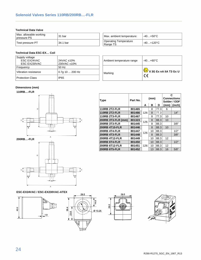
Solenoid Valves Series 110RB/200RB…-FLR
110RB/200RB…-FLR are normally closed solenoid valves for various application duties.
Features
• Normally closed • Pilot operated requires minimum operating pressure differential • Compact size • Extended fittings: No disassembly necessary for brazing • ATEX compliance coils
200RB…-FLR
Selection Table Valves
Type Part No. Kv-Value (m3/h)
Capacity (kW) Liquid line duty Connections Solder / ODF
R290 R1270 (mm) (inch) 110RB 2T2-FLR 801465
0.2 4.2 4.3 6
110RB 2T2-FLR 801466 ¼” 110RB 2T3-FLR 801467 10 200RB 3T3-FLR (mm) 801323
0.4 7.9 8.1 10
200RB 3T3-FLR 801445 3/8” 200RB 4T10-FLR 801446
0.9 18.7 19.2
10 200RB 4T4-FLR 801447 1/2” 200RB 4T3-FLR 801448 3/8” 200RB 4T12-FLR 801449 12 200RB 6T4-FLR 801450
1.6 32.8 33.8 1/2”
200RB 6T12-FLR 801451 12 200RB 6T5-FLR 801452 16 5/8”
Note1: Nominal capacity at +38°C condensing temperature +4°C evaporating temperature. 1 K subcooling and 0.15 bar pressure drop. For selection of other operating condition. please use quick selection tables in the next pages.
Note2: When selecting also observe the information in the operating instructions. Available on EMERSON website www.climate.emerson.com/en-gb.
Selection Table Coils and Accessory
Type Coils Part No. Supply voltage Power Input Description Ambient
temperature Picture
ESC-EX24VAC 801035 24 VAC ±10% 50 Hz 17VA
IP65 acc. EN 60529 test conditions. incl. screw cap with 2x O-ring & fixing retainer
-40…+60°C
ESC-EX230VAC 801036 230 VAC ±10% 50 Hz
17VA
ESC-K01 801034 Screw cap (incl. 2x O-ring & fixing retainer)
Note1: When selecting also observe the information in the operating instructions. Available on EMERSON website www.climate.emerson.com/en-gb.

22 R290-R1270_SGC_EN_1907_R13
Solenoid Valves Series 110RB/200RB…-FLR
SOL…-FLR: Quick Selection (0.15 bar pressure drop)
Condensing temperature
(°C)
R290 Capacity (kW) R290 Valve type Evaporating temperature (°C)
15 10 5 0 -5 -10 -15 -20 -25 -30 -35 -40
65
2.9 2.9 2.8 2.7 2.6 2.6 2.5 2.4 2.3 2.2 2.2 2.1 110RB2…FLR 5.5 5.4 5.2 5.1 4.9 4.8 4.6 4.5 4.3 4.2 4.0 3.9 200RB3…FLR
13.0 12.7 12.4 12.0 11.7 11.3 11.0 10.6 10.2 9.9 9.5 9.2 200RB4…FLR 22.9 22.3 21.7 21.1 20.5 19.9 19.3 18.6 18.0 17.4 16.7 16.1 200RB6…FLR
60
3.2 3.2 3.1 3.0 2.9 2.8 2.8 2.7 2.6 2.5 2.4 2.3 110RB2…FLR 6.0 5.9 5.7 5.6 5.4 5.3 5.1 5.0 4.8 4.7 4.5 4.4 200RB3…FLR
14.3 13.9 13.6 13.2 12.9 12.5 12.2 11.8 11.4 11.1 10.7 10.3 200RB4…FLR 25.0 24.5 23.9 23.3 22.6 22.0 21.4 20.7 20.1 19.5 18.8 18.1 200RB6…FLR
55
3.5 3.4 3.3 3.3 3.2 3.1 3.0 2.9 2.9 2.8 2.7 2.6 110RB2…FLR 6.5 6.4 6.3 6.1 6.0 5.8 5.6 5.5 5.3 5.2 5.0 4.9 200RB3…FLR
15.5 15.1 14.8 14.4 14.1 13.7 13.4 13.0 12.6 12.2 11.9 11.5 200RB4…FLR 27.2 26.6 26.0 25.4 24.7 24.1 23.5 22.8 22.2 21.5 20.8 20.2 200RB6…FLR
50
3.8 3.7 3.6 3.5 3.5 3.4 3.3 3.2 3.1 3.0 2.9 2.9 110RB2…FLR 7.0 6.9 6.7 6.6 6.4 6.3 6.1 6.0 5.8 5.7 5.5 5.3 200RB3…FLR
16.7 16.3 16.0 15.6 15.3 14.9 14.5 14.2 13.8 13.4 13.0 12.6 200RB4…FLR 29.3 28.7 28.0 27.4 26.8 26.1 25.5 24.8 24.2 23.5 22.9 22.2 200RB6…FLR
45
4.0 4.0 3.9 3.8 3.7 3.6 3.5 3.5 3.4 3.3 3.2 3.1 110RB2…FLR 7.5 7.4 7.2 7.1 6.9 6.8 6.6 6.5 6.3 6.1 6.0 5.8 200RB3…FLR
17.8 17.5 17.1 16.8 16.4 16.0 15.7 15.3 14.9 14.5 14.1 13.8 200RB4…FLR 31.3 30.7 30.1 29.5 28.8 28.2 27.5 26.9 26.2 25.5 24.8 24.2 200RB6…FLR
40
4.3 4.2 4.1 4.1 4.0 3.9 3.8 3.7 3.6 3.5 3.5 3.4 110RB2…FLR 8.0 7.9 7.7 7.6 7.4 7.3 7.1 6.9 6.8 6.6 6.4 6.3 200RB3…FLR
19.0 18.6 18.3 17.9 17.5 17.2 16.8 16.4 16.0 15.6 15.3 14.9 200RB4…FLR 33.3 32.7 32.1 31.5 30.8 30.2 29.5 28.8 28.2 27.5 26.8 26.1 200RB6…FLR
35
4.6 4.5 4.4 4.3 4.2 4.1 4.1 4.0 3.9 3.8 3.7 3.6 110RB2…FLR 8.5 8.4 8.2 8.0 7.9 7.7 7.6 7.4 7.2 7.1 6.9 6.7 200RB3…FLR
20.1 19.8 19.4 19.0 18.7 18.3 17.9 17.5 17.1 16.8 16.4 16.0 200RB4…FLR 35.3 34.7 34.1 33.4 32.8 32.1 31.5 30.8 30.1 29.4 28.7 28.0 200RB6…FLR
30
4.8 4.7 4.6 4.6 4.5 4.4 4.3 4.2 4.1 4.0 3.9 3.9 110RB2…FLR 9.0 8.8 8.7 8.5 8.4 8.2 8.0 7.9 7.7 7.5 7.4 7.2 200RB3…FLR
21.2 20.9 20.5 20.2 19.8 19.4 19.0 18.6 18.2 17.8 17.5 17.1 200RB4…FLR 37.3 36.7 36.0 35.4 34.7 34.1 33.4 32.7 32.0 31.3 30.6 29.9 200RB6…FLR
Note: Select the valve type from tables for capacity value corresponding to system (evaporator) cooling capacity. For other pressure drop than 0.15. please use the below correction factors.
Correction factors K ∆P
∆P. bar 0.05 0.1 0.15 0.20 0.25 0.30 0.35 0.40 0.45 0.50 0.55 0.60 0.65 0.70 K∆P 1.73 1.22 1.0 0.87 0.77 0.71 0.65 0.61 0.58 0.55 0.52 0.50 0.48 0.46

23 R290-R1270_SGC_EN_1907_R13
Solenoid Valves Series 110RB/200RB…-FLR
SOL…-FLR: Quick Selection (0.15 bar pressure drop)
Condensing temperature
(°C)
R1270 Capacity (kW) R1270 Valve type Evaporating temperature (°C)
15 10 5 0 -5 -10 -15 -20 -25 -30 -35 -40
65
3.1 3.0 2.9 2.9 2.8 2.7 2.6 2.6 2.5 2.4 2.3 2.3 110RB2…FLR 5.7 5.6 5.5 5.3 5.2 5.1 4.9 4.8 4.7 4.5 4.4 4.2 200RB3…FLR
13.5 13.2 12.9 12.6 12.3 12.0 11.7 11.4 11.0 10.7 10.4 10.0 200RB4…FLR 23.7 23.2 22.7 22.2 21.7 21.1 20.6 20.0 19.4 18.8 18.2 17.6 200RB6…FLR
60
3.3 3.3 3.2 3.2 3.1 3.0 2.9 2.9 2.8 2.7 2.6 2.5 110RB2…FLR 6.3 6.1 6.0 5.9 5.8 5.6 5.5 5.3 5.2 5.1 4.9 4.8 200RB3…FLR
14.8 14.5 14.2 13.9 13.6 13.3 13.0 12.7 12.3 12.0 11.6 11.3 200RB4…FLR 26.0 25.5 25.0 24.5 23.9 23.4 22.8 22.2 21.6 21.0 20.4 19.8 200RB6…FLR
55
3.6 3.6 3.5 3.4 3.4 3.3 3.2 3.1 3.1 3.0 2.9 2.8 110RB2…FLR 6.8 6.7 6.5 6.4 6.3 6.1 6.0 5.9 5.7 5.6 5.4 5.3 200RB3…FLR
16.1 15.8 15.5 15.2 14.9 14.5 14.2 13.9 13.5 13.2 12.8 12.5 200RB4…FLR 28.2 27.7 27.2 26.7 26.1 25.5 25.0 24.4 23.8 23.2 22.6 21.9 200RB6…FLR
50
3.9 3.8 3.8 3.7 3.6 3.6 3.5 3.4 3.3 3.3 3.2 3.1 110RB2…FLR 7.3 7.2 7.1 6.9 6.8 6.7 6.5 6.4 6.2 6.1 5.9 5.8 200RB3…FLR
17.3 17.0 16.7 16.4 16.1 15.8 15.4 15.1 14.7 14.4 14.0 13.7 200RB4…FLR 30.4 29.9 29.3 28.8 28.2 27.7 27.1 26.5 25.9 25.3 24.6 24.0 200RB6…FLR
45
4.2 4.1 4.1 4.0 3.9 3.8 3.8 3.7 3.6 3.5 3.4 3.4 110RB2…FLR 7.8 7.7 7.6 7.4 7.3 7.2 7.0 6.9 6.7 6.6 6.4 6.3 200RB3…FLR
18.5 18.2 17.9 17.6 17.3 16.9 16.6 16.3 15.9 15.6 15.2 14.8 200RB4…FLR 32.5 32.0 31.4 30.9 30.3 29.8 29.2 28.6 27.9 27.3 26.7 26.0 200RB6…FLR
40
4.5 4.4 4.3 4.2 4.2 4.1 4.0 3.9 3.9 3.8 3.7 3.6 110RB2…FLR 8.3 8.2 8.1 7.9 7.8 7.7 7.5 7.4 7.2 7.1 6.9 6.8 200RB3…FLR
19.7 19.4 19.1 18.8 18.4 18.1 17.8 17.4 17.1 16.7 16.3 16.0 200RB4…FLR 34.6 34.1 33.5 33.0 32.4 31.8 31.2 30.6 30.0 29.3 28.7 28.1 200RB6…FLR
35
4.7 4.7 4.6 4.5 4.4 4.4 4.3 4.2 4.1 4.0 4.0 3.9 110RB2…FLR 8.8 8.7 8.6 8.4 8.3 8.1 8.0 7.8 7.7 7.5 7.4 7.2 200RB3…FLR
20.9 20.6 20.3 19.9 19.6 19.3 18.9 18.6 18.2 17.9 17.5 17.1 200RB4…FLR 36.6 36.1 35.6 35.0 34.4 33.8 33.2 32.6 32.0 31.3 30.7 30.0 200RB6…FLR
30
5.0 4.9 4.8 4.8 4.7 4.6 4.5 4.5 4.4 4.3 4.2 4.1 110RB2…FLR 9.3 9.2 9.0 8.9 8.8 8.6 8.5 8.3 8.2 8.0 7.9 7.7 200RB3…FLR
22.0 21.7 21.4 21.1 20.8 20.4 20.1 19.7 19.3 19.0 18.6 18.2 200RB4…FLR 38.7 38.1 37.6 37.0 36.4 35.8 35.2 34.6 34.0 33.3 32.7 32.0 200RB6…FLR
Note: Select the valve type from tables for capacity value corresponding to system (evaporator) cooling capacity. For other pressure drop than 0.15. please use the below correction factors.
Correction factors K ∆P
∆P. bar 0.05 0.1 0.15 0.20 0.25 0.30 0.35 0.40 0.45 0.50 0.55 0.60 0.65 0.70 K∆P 1.73 1.22 1.0 0.87 0.77 0.71 0.65 0.61 0.58 0.55 0.52 0.50 0.48 0.46
24 R290-R1270_SGC_EN_1907_R13
Solenoid Valves Series 110RB/200RB…-FLR
Technical Data Valve
Max. allowable working pressure PS
31 bar Max. ambient temperature: -40…+50°C
Test pressure PT 34.1 bar Operating Temperature Range TS -40…+120°C
Technical Data ESC-EX… Coil
Supply voltage ESC EX24VAC ESC EX230VAC
24VAC ±10% 230VAC ±10%
Ambient temperature range -40…+60°C
Frequency 50 Hz
Marking II 3G Ex nA IIA T3 Gc U
Vibration resistance 0.7g 10 ... 200 Hz
Protection Class IP65
Dimensions (mm)
110RB…-FLR
200RB…-FLR
ESC-EX24VAC / ESC-EX230VAC-ATEX
Type Part No. (mm)
C Connections Solder / ODF
A B D (mm) (inch) 110RB 2T2-FLR 801465
126 8 77.3 6
110RB 2T2-FLR 801466 8 77.3 14” 110RB 2T3-FLR 801467 8 77.3 10 200RB 3T3-FLR (mm) 801323
126 8 88.3 10
200RB 3T3-FLR 801445 8 88.3 3/8” 200RB 4T10-FLR 801446
126
8 88.3 10 200RB 4T4-FLR 801447 10 88.3 1/2” 200RB 4T3-FLR 801448 8 88.3 3/8” 200RB 4T12-FLR 801449 10 88.3 12 200RB 6T4-FLR 801450
126 10 88.3 1/2”
200RB 6T12-FLR 801451 10 88.3 12 200RB 6T5-FLR 801452 13 88.3 16 5/8”

25 R290-R1270_SGC_EN_1907_R13
Pressure Transmitter
PT5N-…-FLR Pressure Transmitter PT5N-...-FLR converts a pressure into a linear electrical output signal and is intended for use in hydrocarbons operated air conditioning and refrigeration systems as well as heat pumps.
The pressure transmitter can only be used in hazardous area defined by zone 2 (category 3). PT5N-…-FLR : II 3 G Ex ec IIC T4 Gc PT4-M60-FLR: II 3 G Ex nA IIA T4 Gc U
Features • Hybrid film stainless steel measuring cell with a diaphragm.
installed in a stainless steel housing • With output signal 4…20 mA and 2-wire connection for the
precise operation of superheat, compressor or fan control systems
• Calibrated for specific temperature and pressure ranges • Calibrated pressure ranges with ±±±±1% accuracy performance • Fully hermetic • Vibration, shock and pulsation resistant • Protection class IP67 with mounted plug and cable assembly
• PT5N-xxP-FLR with 6x40 mm stainless steel tube and integrated brazing neck for easy mounting in applications requiring a fully hermetic system solution.
• Easy install M12 electrical connection with pre-assembled cable assembly available.
PT5N-…P-FLR
Selection Table Pressure Transmitter
Type Part No. Pressure range for signal
output (bar)*
Output signal
Medium temperature
range
Max. working pressure PS
(bar)*
Pressure Connection Single
pack Multipack
25 pcs PT5N-07P-FLR 805390 805390M -0.8...7
4…20mA -30...+120°C 27 6 mm tube x 40 mm
long PT5N-30P-FLR 805389 805389M 0…30 60 Note1: *) Sealed gauge pressure Note2: When selecting also observe the information in the operating instructions. Available on EMERSON website www.climate.emerson.com/en-gb
Selection Table Cable Assembly
Type Part No. Cable Length** Temperature Range
Single pack
PT4-M60 FLR 804806 6.0 m -40…+70°C
Note: **) Longer length of the electrical connection cable beyond 6.0 m must be verified by user in term of output signal as well as EMC within The qualification /certification of PT5N-…P-FLR is valid only in conjunction with PT4-M60-FLR connector.

26 R290-R1270_SGC_EN_1907_R13
PT5N-…-FLR Pressure Transmitter
Technical Data PT5N-…-FLR
Supply voltage (polarity protected)
Nominal: 24VDC Range: 10…30VDC
Electrical connection
via PT4-M60-FLR plug and cable assembly
Operating current circuit
Applicable Driver/controller must contain intrinsically-safe resistive circuit and insured maximum supply voltage below 30VDC and maximum current below 100 mA.
Maximum ≤ 23 mA 4…20 mA output
Ui ≤ 30 V. Ii ≤ 100 mA. Pi ≤ 750mA internal inductance Li = 0 nH
internal capacitance Ci = 0 nF
Medium compatibility All flammable refrigerants of A3 group; mineral-. alkyl benzene and ester lubricants
Protection class (EN60529)
IP67 (PT4-M60 FLR)
Load resistance RL ≤ Ub - 7.0V_ 0.02A
Materials Housing
pressure connection
Stainless steel 1.4404 / AISI316L Stainless steel 1.4301 / AISI 304
Response time ≤ 2 ms Weight PT5N-xxP-FLR: ~ 103 g
Vibration at 15…2000Hz 20 g acc. to IEC 60068-2-6
Markings
2014/34/EU: EN 60079-0:12 + A11:13 EN 60079-11: 12 EN 60079-26: 15 2014/30/EU: EN 61326-2-3. EN 50121-3-2
Temperatures Transport and storage
Operating ambient housing Medium
-50…+100°C -25…+85°C -30…+120°C
ATEX II 3 G Ex ec IIC T4 Gc
Accuracy Performance
Type Total error 1 Temperature range Note:
PT5N-07P-FLR ≤ ±1% FS -30…+20°C 1) Total error includes non-linearity. hysteresis. repeatability as well as offset and span drift due to the temperature changes. %FS is related to Percentage of Full Scale.
PT5N-30P-FLR ≤ ±1% FS +10…+50°C
≤ ±2% FS -10…+80°C
Technical Data PT4-M60 FLR
Operating voltage 30 VDC Design angled
Protection class IP65 Marking
II 3 G
Ex nA IIA T4 Gc U Ambient temperature -40…+70°C
Dimensions (mm)
PT5N-xxP-FLR Date of manufacture visible on PT5N-…P-FLR label
PT4-M60 FLR M12 Plug
YYMMDD-XXX-XX-XXXX Date (year-month-day) 3 digits of the order number Order position Single part number

27 R290-R1270_SGC_EN_1907_R13
Pressure Controls
PS4-…ATEX Pressure Switch with fixed setting
Features
• High- and low-pressure switches • With molded cable • Protection IP67 • TÜV approved • Minimum lot size for multipack 100 pieces • Other settings are not available
Marking
• ENEC05 and CE0035 according to PED
• II 3G Ex nA IIA T2Gc U
PS4-…ATEX
Selection Table
Type Part No. Setting (bar)
EN 12263 Contact function
Application Pressure
connection Cut-out Cut-in
Low pressure switches with automatic reset; Open on falling pressure
PS4-W1-0.2/1.4 bar ATEX 808306
0.2 1.4 PSL open on falling
pressure low pressure 6 mm
808308*
PS4-W1 0.6/1.8 bar ATEX 808301
0.6 1.8 808303*
High pressure switches with automatic reset; open o n rising pressure
PS4-W1 18/24 bar ATEX 808304*
18 24 PSH
open on rising pressure high pressure 6 mm
808305
PS4-W1 20/26 bar ATEX 808300
20 26 808302*
Note1: *) Single pack Note2: When selecting also observe the information in the operating instructions. Available on EMERSON website www.climate.emerson.com/en-gb.
Technical Data
Max. allowable working pressure PS
PS4-W1-0.2/1.4 bar ATEX PS4-W1 0.6/1.8 bar ATEX PS4-W1 18/24 bar ATEX PS4-W1 20/26 bar ATEX
22.7 bar 22.7 bar 37 bar 37 bar
Type of electrical contact Single pole single throw (SPST)
Temperature range Medium Ambient Storage
-35…+135°C -30…+65°C -30…+80°C
Test pressure PT PS4-W1-0.2/1.4 bar ATEX PS4-W1 0.6/1.8 bar ATEX PS4-W1 18/24 bar ATEX PS4-W1 20/26 bar ATEX
25 bar 25 bar 41 bar 41 bar
Electrical rating 50 mA max. at 24VDC Compatibility R290, R1270 Protection class (EN60259) IP67
Cable length 3 m Vibration resistance 4 g (10...250Hz) Electrical connection
Cable version
Cable color
18 AWG 0.8 mm2. 600 V (max. 125°C) LP: (blue) HP: (black)
Marking ENEC05 and CE0035 acc. PED
II 3G Ex nA IIA T2Gc U
It is manadatory to protect pressure switch agains t supply voltage higher than 30 VDC and operating c urrent over 50 mA at any time.

28 R290-R1270_SGC_EN_1907_R13
PS4-…ATEX Pressure Switch with fixed setting
Pressure Setting (Cut-out) Drifting:
PS4-…ATEX factory setting is at 23°C room temperature however, the setting will drift by other ambient and fluid temperatures. The table indicates the amount of drift in function of ambient and media temperature.
PS4 safety pressure cut-out Brazing connection
PS4 safety pressure cut-out Thread connection
Media temp. (°C)
Ambient temperature ( °C) 0 10 23 25 30 35 40 45 50 55
Total drift of cut -out set point (%) 80 +5 +2,8 * * * * -3.7 -4.8 -5.9 -7.0
85 +5 +2,8 * * * * -3.8 -4.9 -6.0 -7.1
90 +5 +2,8 * * * * -3.9 -5.0 -6.1 -7.2
95 +5 +2,8 * * * * -4.0 -5.1 -6.2 -7.3
100 +5 +2,8 * * * * -4.1 -5.2 -6.3 -7.4
105 +5 +2,8 * * * -3.1 -4.2 -5.3 -6.4 -7.5
110 +5 +2,8 * * * -3.2 -4.3 -5.4 -6.5 -7.6
115 +5 +2,8 * * * -3.3 -4.4 -5.5 -6.5 -7.6
120 +5 +2,8 * * * -3.4 -4.5 -5.5 -6.6 -7.7
125 +5 +2,8 * * * -3.4 -4.5 -5.6 -6.7 -7.8
130 +5 +2,8 * * * -3.5 -4.6 -5.7 -6.8 -7.9
135 +5 +2,8 * * * -3.6 -4.7 -5.8 -6.9 -8.0
Media temp. (°C)
Ambient temperature ( °C) 0 0 23 25 30 35 40 45 50 55
Total drift of cut -out set point (%) 80 +5 +2,8 * * * * -3.7 -4.8 -5.9 -7.0
85 +5 +2,8 * * * * -3.9 -5.0 -6.1 -7.2
90 +5 +2,8 * * * * -4.1 -5.2 -6.3 -7.4
95 +5 +2,8 * * * -3.2 -4.3 -5.4 -6.5 -7.6
100 +5 +2,8 * * * -3.4 -4.5 -5.6 -6.7 -7.8
105 +5 +2,8 * * * -3.6 -4.7 -5.8 -6.9 -8.0
110 +5 +2,8 * * * -3.8 -4.9 -6.0 -7.1 -
115 +5 +2,8 * * * -4.0 -5.1 -6.2 -7.3 -
120 +5 +2,8 * * -3.2 -4.2 -5.3 -6.4 -7.5 -
125 +5 +2,8 * * -3.4 -4.5 -5.5 -6.6 -7.7 -
130 +5 +2,8 * * -3.6 -4.7 -5.7 -6.8 -7.9 -
135 +5 +2,8 * * -3.8 -4.9 -6.0 -7.0 - -
Note: European standard for high safety pressure switches permits maximum +0% / -8% of the setting at extreme operating conditions. *) The device will cut-out anywhere from 0 to -3% from the cut-out. For low pressure switches with settings between 0 to 6.9 bar:
• type approval, version (W) according to EN 12263: -0 / +1 bar • standard version (A) according EN 12263 -0.5 / +0.5 bar
Dimensions (mm)

29 R290-R1270_SGC_EN_1907_R13
System Protectors and Moisture Indicators
Hermetic Liquid Line Filter Driers ADK-…FLR
Selection Table Technical Data
Type Part No.
Connection
ODF
Flow capacity (kW)
Pressure drop R290 R1270
0.07bar 0.07bar ADK-032S FLR 803650 1/4" 9.6 10 ADK-036MMS FLR 803651 6 mm 8.8 9.1 ADK-052S FLR 803652 1/4" 11.8 12.3 ADK-056MMS FLR 803653 6 mm 10.9 11.4 ADK-053S FLR 803654 3/8" 17.9 18.6 ADK-0510MMS FLR 804066 10 mm 17.9 18.6 ADK-082S FLR 804067 1/4" 13.1 13.6 ADK-086MMS FLR 804068 6 mm 11.7 12.2 ADK-083S FLR 804069 3/8" 18.0 18.7 ADK-0810MMS FLR 804070 10 mm 18.0 18.7 ADK-084S FLR 804071 1/2" 29.3 30.5 ADK-0812MMS FLR 804072 12 mm 28.8 30 ADK-163S FLR 804073 3/8" 20.5 21.3 ADK-1610MMS 804074 10 mm 20.5 21.3 ADK-164S FLR 804075 1/2" 39.4 41.0 ADK-1612MMS FLR 804076 1 mm 35.4 36.8 ADK-165S FLR 804077 5/8" /16 mm 54.4 56.7 ADK-304S FLR 804078 1/2" 39.5 41.4 ADK-305S FLR 804079 5/8" /16 mm 57.8 60.2 ADK-307S FLR 804080 7/8" /22 mm 72.6 75.5 ADK-417S FLR 804081 5/8" /16 mm 85.3 88.8 ADK-757S FLR 804082 7/8" /22 mm 115.5 120.3
Max. working pressure PS 35 bar Test pressure PT 38.5 bar Temperature range
Medium / Ambient -45…+65°C
Fluid group I Solder connections Copper ODF Shell Steel Paint Epoxy powder paint Protection 500+ hours salt spray test Package Individual packaged Standards EN 14276-1
Note: When selecting also observe the information in the operating instructions. Available on website www.climate.emerson.com/en-gb.
Dimensions (mm)
Type Connection ODF
(mm) Type Connection ODF
(mm) A Ø F A Ø F
ADK-032S-FLR 1/4" 70.1 44.0 ADK-0812MMS-FLR 12 mm 102.6 63.5
ADK-036MMS-FLR 6 mm 70.1 44.0 ADK-163S-FLR 3/8" 126.6 63.5
ADK-052S-FLR 1/4" 85.3 63.5 ADK-1610MMS-FLR 10 mm 126.6 63.5
ADK-056MMS-FLR 6 mm 85.3 63.5 ADK-164S-FLR 1/2" 127.0 63.5
ADK-053S-FLR 3/8" 84.8 63.5 ADK-1612MMS-FLR 12 mm 127.0 63.5
ADK-0510MMS-FLR 10 mm 84.8 63.5 ADK-165S-FLR 5/8" / 16 mm 127.6 63.5
ADK-082S-FLR 1/4" 102.7 63.5 ADK-304S-FLR 1/2" 193.6 76.2
ADK-086MMS-FLR 6 mm 102.6 63.5 ADK-305S-FLR 5/8" / 16 mm 194.2 76.2
ADK-083S-FLR 3/8" 102.1 63.5 ADK-307S-FLR 7/8" / 22 mm 193.6 76.2
ADK-0810MMS-FLR 10 mm 102.1 63.5 ADK-417S-FLR 5/8" / 16 mm 199.9 88.9
ADK-084S-FLR 1/2" 102.5 63.5 ADK-757S-FLR 7/8" / 22 mm 337.4 88.9
ADK-…FLR filter-driers are used for protection of systems against contaminant.
Features
• Solid block • Hermetic design • Rugged steel shells • Corrosion resistant epoxy paint • Cushioned flow for non-turbulent performance • High water adsorption capacity • High acid adsorption capacity • High filtration capacity / efficiency • Max. working pressure PS: 35 bar
ADK-…FLR

30 R290-R1270_SGC_EN_1907_R13
Bi-flow Liquid Line Filter Driers BFK-…FLR
Selection Table Technical Data
Type Part No.
Connection size
& Type
Flow capacity (kW)
Pressure drop R290 R1270
0.07bar 0.07bar BFK-052S-FLR * 1/4” ODF 8.1 8.3 BFK-083S-FLR * 3/8” ODF 14.4 14.9 BFK-163S-FLR * 3/8” ODF 18.6 19.3 BFK-084S-FLR * 1/2” ODF 18.7 19.4 BFK-164S-FLR * 1/2” ODF 29.1 30.2 BFK-165S-FLR * 5/8” ODF 30.8 31.9 BFK-305S-FLR * 5/8”/ 16 mm ODF 41.0 42.5 BFK-307S-FLR * 7/8”/ 22 mm ODF 48.7 50.5 BFK-309S FLR 804090 1 1/8” ODF 56.5 58.5
Max. working pressure PS 45 bar Test pressure PT 46.9 bar Temperature range
Medium / Ambient -30…+65°C
Fluid group I Solder connections Copper ODF Shell Steel Paint Epoxy powder paint Protection 500+ hours salt spray test Package Individual packaged Standards EN 14276-1 Marking HP
Note1: When selecting also observe the information in the operating instructions. Available on website www.climate.emerson.com/en-gb.
Note2: *) Order upon request and agreement. Delivery after Part No. setup.
Dimensions
Type Connection size & type
(mm) A B F
BFK-052S 1/4” ODF 106 9.5 64 BFK-083S 3/8” ODF 134 11
BFK-084S 1/2” ODF 136 12.7 BFK-163S 3/8” ODF 155 11
76
BFK-164S 1/2” ODF 156 12.7 BFK-165S 5/8” ODF 163 16 BFK-305S 5/8” ODF 236 16 BFK-307S 7/8” ODF 251 19 BFK-309S 1-1/8” ODF 251 24
BFK-…FLR filter-driers are used for protection of systems against contaminant.
Features
• Solid block • Hermetic design • Rugged steel shells • Corrosion resistant epoxy paint • Cushioned flow for non-turbulent performance • High water adsorption capacity • High acid adsorption capacity • High filtration capacity / efficiency • No CE marking according art. 4.3 PED • Max. working pressure PS: 35 bar
BFK-…FLR

31 R290-R1270_SGC_EN_1907_R13
Moisture Indicator MIA…-FLR
Features • Fully hermetic • Lower Pressure drop • Corrosion free stainless-steel body • Crystal Indicator element for long lifetime and reliability • Easily determination of moisture content • Sensitive indicator with calibrated four colors. Conforms to
requirement of most compressor manufacturers • Large clear viewing area • ODF extended tube configurations suitable for all commercial
applications
MIA Moisture Indicator
Selection Table and Dimensions
Type Part No. For tube outside
diameter
Height A
Length B
Weight
Type Part No. For tube outside
diameter
Height A
Length B
Weight
(mm) (mm) (g) (mm) (mm) (g) MIA 014-FLR 805895 1/4’’ 25.7 98.0 60 MIA M06-FLR 805901 6 mm 25.9 98.0 60 MIA 038-FLR 805896 3/8’’ 28.5 109.0 70 MIA M10-FLR 805894 10 mm 28.5 109.0 70 MIA 012-FLR 805897 1/2’’ 31.8 113.0 75 MIA M12-FLR 805902 12 mm 28.5 113.0 75 MIA 058-FLR 805898 5/8’’ 31.8 108.5 85 MIA M28-FLR 805903 28 mm 43.5 122.5 190 MIA 078-FLR 805899 7/8’’ 37.8 122.5 150 MIA M10S-FLR 805904 10 mm 28.7 119 75 MIA 118-FLR 805900 1 1/8’’ 43.5 122.5 190 MIA M12S-FLR 805905 12 mm 28.5 113 75
Note: When selecting also observe the information in the operating instructions. Available on EMERSON website www.climate.emerson.com/en-gb
Technical Data
Maximum working pressure PS 35 bar Pressure drop negligible
Test pressure PT 49.5 bar Operating temperature TS -40…+100°C
Medium compatibility R290, mineral-. alkyl benzene and ester lubricants
External leakage (100%-production tested with Helium- Spectrometer)
5.0x10⁻⁶ mbar l/sec = 4.9x10⁻⁶ cc/sec
Connections ODF extended copper tubes. solder connections only
Standards EN 12178
Determining the Moisture Content with the Color Cod e
Refrigerant Liquid
temperature (°C)
Moisture content in mg Water per kg refrigerant (pp m)
blue purple fuchsia rose Dry Caution Caution wet
R290 25 2 4 9 14 38 5 8 18 29 52 10 16 36 59
Note: In area “Caution” and “Caution wet” filter drier should be changed. Section1ende

32 R290-R1270_SGC_EN_1907_R13
Section 2: Products for non-explosive Environment
Product Material Compatible with
R290 / R1270
only for non-explosive Environment
Section2anfang

33 R290-R1270_SGC_EN_1907_R13
Electronic Controllers
EXD-HP1/2 Stand-alone Superheat/Economizer Controll er In compliance with EN/IEC 60335-2-40/89 EXM/L valves are qualified to use with R290. EXD-HP1/2 are stand-alone universal superheat and or economizer controllers for heat pumps, heating units, air conditioning and close control units as well as refrigeration display cases.
Features
• Self-adapting superheat/economizer control in conjunction with EMERSON stepper motor driven electronic expansion valves EXM/EXL
• Discharge hot gas temperature control by wet refrigerant vapor/vapor injection to compressor
• EXD-HP1: Controller with one EXV output • EXD-HP2: Controller with two independent EXV outputs • Controllers as slave with Modbus (RTU) communication
capability. All data (read/write) accessible by any third-party controller having modbus communication (RTU)
• Upload/download key (accessory) for transmission of parameter settings among controllers with the same setting
• Low pressure switch and freeze protection function • Manual positioning of valve(s) • Limitation of evaporating pressure (MOP) • Low/high superheat alarm • Monitoring of sensors and sensor wiring and detection of
sensor and wiring failures • Integrated display (3-digits LEDs) and key board • Electrical connection via plug-in type screw terminals (included
with controller) • DIN rail mounting housing • OEM product: Box order quantities: 20 pieces (Multi-pack)
EXD-HP2
Selection Table
Type Description Part No.
Multipack (20 pcs) Single pack
Controllers
EXD-HP1 with 1 EXV output 807836M 807836 EXD-HP2 with 2 EXV outputs 807837M 807837
Valves / Coils
EXM-B0A
Electronic expansion valve
800399M - EXM-B0B 800400M - EXM-B0D 800401M - EXM-B0E 800402M - EXM-125 Coil 12 VDC 800403M - EXL-B1F
Electronic expansion valve 800405M -
EXL-B1G 800406M - EXL-125 Coil 12 VDC 800407M -
Temperature sensor
ECP-P30 Temperature sensor with 3 m cable - 804495
Pressure transmitters / plug and cable assembly
PT5N-07P Sensing pressure range -0.8…7 bar, brazing connection 805350M (25 pcs) 805350 PT5N-30P Sensing pressure range 0…30 bar, brazing connection 805352M (25 pcs) 805352 PT4-M15 M12 Plug and cable, 1.5 m cable length 804803M 804803 PT4-M30 M12 Plug and cable, 3.0 m cable length 804804M 804804 PT4-M60 M12 Plug and cable, 6.0 m cable length 804805M 804805 Note1: For further detail please see pages of EXM/L and PT5N Technical Bulletin.
EXD-HP1/2 have potential ignition source and do not comply with ATEX requirements. Installation only i n “non explosive location”.

34 R290-R1270_SGC_EN_1907_R13
EXD-HP1/2 Stand-alone Superheat/Economizer Controll er
Technical Data
EXD-HP1/2
Supply voltage 24 VAC/DC ±10% Protection class IP20
Power consumption EXD-HP1: Max. 15VA EXD-HP2: Max. 20VA
Housing Self-extinguishing ABS
Digital inputs EXD-HP1: Two, each potential free EXD-HP2: Three, each potential free Mounting DIN rail mounted
Relay output SPDT contacts. AgSnO Inductive (AC15) 24 V AC: 1 A Resistive: 24 VAC/DC: 4 A
Temperatures storage operating
-20…+65°C -10…+60°C
Plug-in connector size Removable screw version wire size 0.14…1.5 mm2 Relative humidity 0…85% RH, non-condensing
Applied directive LVD, EMC, RoHS Weight 175 g
Compliance with DIN EN60335-1 DIN EN 55014-1, DIN EN 55014-2
Marking
Selectable Refrigerants R22, R134a, R410A, R32, R407C, R290
Input Sensors. Output Valves
Description Specification
Temperature input ECP-P30 (3 m cable length) Range: -30…+150°C
Pressure sensor input PT5N Signal: 4…20 mA
Electronic expansion valves (stepper motor) output
EXM and EXL series
Dimensions (mm)
70
3535
117
,5
Ø4,3
110
125
,5
45
59,5

35 R290-R1270_SGC_EN_1907_R13
EXD-SH1/2 Controller for EX4-7-…-FLR with ModBus Co mmunication Capability EXD-SH1/2 are stand-alone universal superheat and or temperature controllers for air conditioning units or refrigeration systems.
Features
• EXD-SH1: Control of one valve • EXD-SH2: Control of two valves in two independent circuits • Main function
Circuit 1 Circuit 2 EXD-SH1 Superheat or temperature control EXD-SH2 Superheat or temperature control Superheat Control
• Other functions: Limitation of evaporating pressure (MOP), Low pressure switch, freeze protection and manual positioning of valve(s)
• Self-adapting superheat control function in conjunction with EMERSON EX4-7-…-FLR
• Modbus (RTU) communication • Integrated keyboard with two lines display • Monitoring of sensors and detection of sensor (ECN…/PT5N…P-FLR)
/stepper motor wiring failures • Optional upload/download key (accessory) for transmission of parameter
settings among controllers with the same setting • Low/high superheat alarm as well as other function alarms • Electrical connection via plug-in type screw terminals included with
controller and Micro Molex EXD-M03 (must be ordered separately) • DIN rail mounting housing Note: Software modification for selection refriger ants R290 / R1270 is pending. (Contact local sales offices for availab ility)
EXD-SH2
EXD-M03
Selection Table
Type Description Part No.
Multipack (25 pcs) Single pack
Controllers
EXD-SH1 Controller for single refrigeration circuit - 807855 EXD-SH2 Controller for two independent refrigeration circuits - 807856 EXD-M03 Molex terminal with 3 m wires - 807865 Valves / plug and cable assembly
EX4-7…FLR Details, please see page 7-10 page 7-10 page 7-10 EXV-M60 FLR M12 Plug for EX4-7…-FLR, loose wires, 6m cable length - 804666
Temperature sensor
ECN-N30 Temperature sensor with 3 m cable - 804496 ECN-N60 Temperature sensor with 6 m cable - 804497 Pressure transmitters / plug and cable assembly
PT5N-07P-FLR Sensing pressure range -0.8…7 bar, brazing connection 805390M 805390 PT5N-30P-FLR Sensing pressure range 0…30 bar, brazing connection 805389M 805389 PT4-M60 FLR M12 Plug and cable, 6.0 m cable length - 804806
Uninterruptible Power supply
ECP-024 Backup battery with two outputs for two controllers - 804558 K09-P00 Electrical Terminal Kit for ECP-024 - 804560 EXD-PM Super cap for only EXD-SH1
(two pieces of EXD-PM required for one EXD-SH2) - 807854
EXD-SH1/2, ECP-024 & EXD-PM have potential ignition source and do not comply with ATEX requirements. I nstallation only in “non explosive location”.

36 R290-R1270_SGC_EN_1907_R13
EXD-SH1/2 Controller for EX4-7-…-FLR with ModBus Co mmunication Capability
Description of Functions
Controllers are featured with a main function as superheat controller or temperature controller. The main function is selectable.
Superheat Control of Evaporators or Economizers
This function requires the connection of temperature sensor(s) as well as pressure transmitters(s). The other functions are: • MOP control: enables the limitation of saturated temperature of suction line (outlet of evaporator/economizer) • Low pressure behaves similar to low pressure switch including alarm conditions • Freeze protection is based on saturated temperature from converting measuring suction pressure. It provides alarm condition
below certain adjusted temperature.
Temperature Controller
The function is to maintain desired temperature by modulating refrigerant mass flow. If controller is operated as temperature controller. the connection of pressure transmitter is not required. In order to fulfill varieties of the applications. the refrigerant mass flow variation can be set according temperature increase or decrease.
Temperature control in normal sense (A: Mass flow increases if temperature rises)
Valve opening % 100% Temperature 0%
1tAL 1tst 1tAH
Temperature control in reverse sense (B: Mass flow decreases if temperature rises)
Valve opening % 100% Temperature 0% 1tAL 1tst/ 1tAH
Examples of Applications:
o Temperature control by throttling suction mass flow (normal sense. A) o Temperature control by modulating hot gas into inlet or outlet of evaporators (reverse sense. B) o Discharge temperature control by injecting liquid (normal sense. A)
Head pressure control by means of temperature control (normal sense. A)
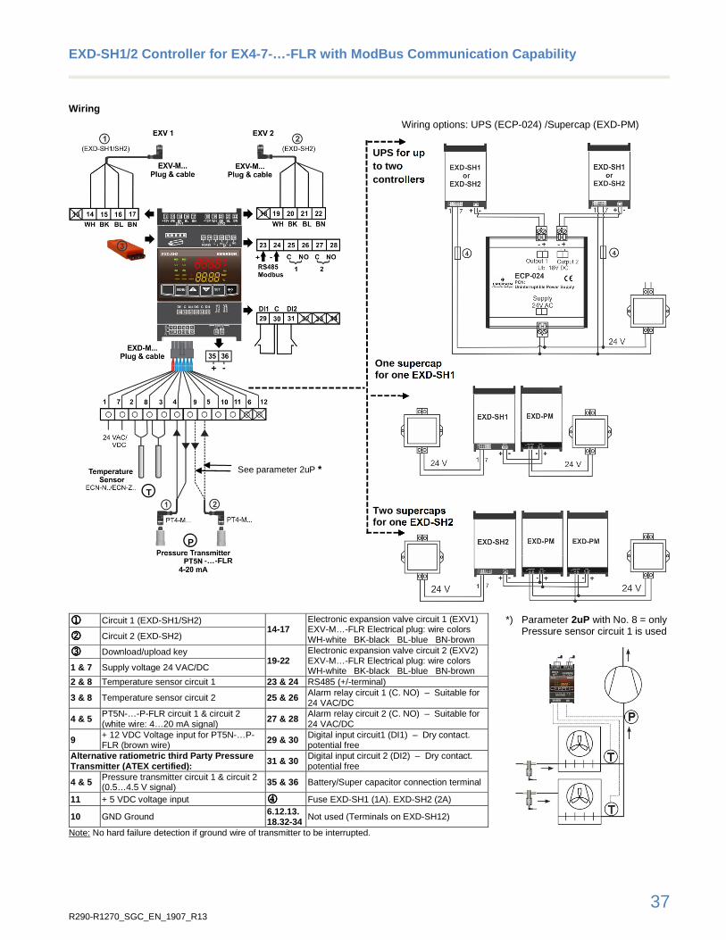
37 R290-R1270_SGC_EN_1907_R13
EXD-SH1/2 Controller for EX4-7-…-FLR with ModBus Co mmunication Capability
Wiring
Wiring options: UPS (ECP-024) /Supercap (EXD-PM)
1111 Circuit 1 (EXD-SH1/SH2)
14-17 Electronic expansion valve circuit 1 (EXV1) EXV-M…-FLR Electrical plug: wire colors WH-white BK-black BL-blue BN-brown
*) Parameter 2uP with No. 8 = only Pressure sensor circuit 1 is used
2222 Circuit 2 (EXD-SH2)
3333 Download/upload key 19-22
Electronic expansion valve circuit 2 (EXV2) EXV-M…-FLR Electrical plug: wire colors WH-white BK-black BL-blue BN-brown
1 & 7 Supply voltage 24 VAC/DC
2 & 8 Temperature sensor circuit 1 23 & 24 RS485 (+/-terminal)
3 & 8 Temperature sensor circuit 2 25 & 26 Alarm relay circuit 1 (C. NO) – Suitable for 24 VAC/DC
4 & 5 PT5N-…-P-FLR circuit 1 & circuit 2 (white wire: 4…20 mA signal) 27 & 28 Alarm relay circuit 2 (C. NO) – Suitable for
24 VAC/DC
9 + 12 VDC Voltage input for PT5N-…P-FLR (brown wire) 29 & 30 Digital input circuit1 (DI1) – Dry contact.
potential free Alternative ratiometric third Party Pressure Transmitter (ATEX certified) : 31 & 30 Digital input circuit 2 (DI2) – Dry contact.
potential free
4 & 5 Pressure transmitter circuit 1 & circuit 2 (0.5…4.5 V signal) 35 & 36 Battery/Super capacitor connection terminal
11 + 5 VDC voltage input 4444 Fuse EXD-SH1 (1A). EXD-SH2 (2A)
10 GND Ground 6.12.13. 18.32-34 Not used (Terminals on EXD-SH12)
Note: No hard failure detection if ground wire of transmitter to be interrupted.
T
UPS for up to two controllers
One supercap for one EXD-SH1
See parameter 2uP *
P
Two supercaps for one EXD-SH2
-…-FLR

38 R290-R1270_SGC_EN_1907_R13
EXD-SH1/2 Controller for EX4-7-…-FLR with ModBus Co mmunication Capability
Technical Data: EXD-SH1/2
Supply voltage 24 VAC/DC ±10%. 50/60 Hz Mounting DIN rail mounted
Power consumption EXD-SH1: Max. 25 VA EXD-SH2: Max. 50 VA
Temperatures
storage operating/ surrounding
-25…+60°C 0…+55°C
Terminals 1 to 12 Suitable for 12 poles molex plug Relative humidity 20…85% non-condensing
Terminals 13 to 36 Suitable for removable screw version: wire size 0.14…1.5 mm2 Included in controller delivery
Accessory (12 poles molex plug with 3 m cable)
Type: EXD-M03 (to be ordered separately)
Protection class IP 00 Housing Self-extinguishing ABS
Compliance EMC, RoHS Weight 320 g
Marking
Input, Output EXD-SH1/2
Description Specification
Analogue input(s): NTC Temperature sensor ECN-N… (-45°C…+50°C sensing range)
Analogue input(s): 4…20 mA pressure transmitters Analogue input(s): 0.5…4.5 V pressure transmitters
PT5N-…-P-FLR Third party ratio metric pressure transmitters (ATEX certified) (total error: ≤ 1%)
Digital input(s) Dry contact. potential free
Digital output(s): Alarm relay(s) Contact is closed: During alarm condition Contact is open: During normal operation and supply power OFF
Resistive Load 24 VAC/DC. max. 1 A Inductive Load 24 V AC. max. 0.5 A
Communication RS485 RTU Modbus. two wires
Stepper motor output Valves: EX4-7-…-FLR
Technical Data Optional EXD-PM Supercap
Supply voltage 24 VAC/DC ±10%. 50/60 Hz Protection class IP 20
Output voltage 12 VDC Mounting DIN rail mounted
Max. output current 1.2 A 350 mA during charging
Temperatures
Storage operating/ surrounding
-20…+70°C -10…+60°C
Power consumption 12 VA Housing Self-extinguishing ABS
Terminals Suitable for removable screw version: wire size 0.14…1.5 mm2
Relative humidity 20…85% non-condensing
Output: to driver/controller
Suitable for one EXD-SH1 Two EXD-PM for one EXD-SH2 Marking
Charging time 60 seconds Weight 125 g
Max. cable length between EXD-PM and EXD-SH1/2
50 cm AWG18 wire size

39 R290-R1270_SGC_EN_1907_R13
EXD-SH1/2 Controller for EX4-7-…-FLR with ModBus Co mmunication Capability
Technical Data Optional Uninterruptible Power Suppl y ECP-024
Backup battery type Lead acid gel rechargeable battery Mounting DIN rail mounted
Number of backup batteries
2. each 12 VDC. 0.8 Ah Temperatures
Storage operating/ surrounding
-20…+65°C -10…+60°C
Supply voltage 24 VAC ±10%. 50-60 Hz
Housing Aluminum
Output voltage. UB 18 VDC Relative humidity < 90% non-condensing
Number of outputs to drivers
2 Connection Screw terminals for wire size 0.5…2.5 mm2
Battery recharge time approximately 2 hours Accessories: Terminals K09-U00
Protection class IP 20 Weight 1200 g
Marking
Dimensions (mm)
EXD-SH1/2 or EXD-PM ECP-024
70
3535
117,5
Ø4,3
110
12
5,5
45
59,5

40 R290-R1270_SGC_EN_1907_R13
EC3-P32 / -P33 Superheat Controller & Standard ECD- 002 EC3-P32 / -P33 are stand-alone universal superheat controllers. EC3-P32 offers remote access with built-in TCP/IP Ethernet communications and WebServer functionality. Any standard WebBrowser (e.g. Internet Explorer® or Mozilla Firefox) can be used for monitoring or parameter setting. EC3-P33 has no network communication.
Features EC3-P33 / EC3-P32
• Superheat control in conjunction with EMERSON stepper motor driven Electrical Control Valves EX4-7-…FLR
• Low superheat alarm and MOP function • Feed through of 4…20mA signal from evaporator pressure
sensor to analogue output. This may also be connected to pressure input of any other controller to avoid need for multiple pressure sensors
• Monitoring of sensors and sensor wiring and detection of sensor and wiring failures
• Intelligent alarm management in order to protect the compressor i.e. fail-safe operation
• Integral rechargeable battery to close electrical control valve in case of power loss
• Electrical connection via plug-in type screw terminals • Aluminum housing for DIN rail mounting
EC3-P32
Additional Features EC3-P32 only
• High superheat alarm • Low pressure switch function/alarm • Freeze protection function/alarm • Pump down function
EC3-P33 with ECD -002
Selection Table
Type Description Part No.
Multipack (25 pcs) Single pack
Controllers EC3-P33 Universal superheat controller with network communication - 807858 K03-X33 Terminal kit EC3-P33 - 807645 EC3-P32 Universal superheat controller without network communication - 807857 K03-X32 Terminal kit EC3-P32 - 807644 ECD-002 Optional Display/keypad unit - 807657 Temperature sensor ECC-N10
Connection cable EC3 to ECD-002
1 m cable length - 807860 ECC-N30 3 m cable length - 807861 ECC-N50 5 m cable length - 807862
Valves / plug and cable assembly EX4-7…FLR Details, please see page 7-10 page 7-10 page 7-10 EXV-M60 FLR M12 Plug for EX4-7…-FLR, loose wires, 6m cable length - 804666
Temperature sensor
ECN-N30 Temperature sensor with 3 m cable - 804496 ECN-N60 Temperature sensor with 6 m cable - 804497 Pressure transmitters / plug and cable assembly PT5N-07P-FLR Sensing pressure range -0.8…7 bar, brazing connection 805390M 805390 PT5N-30P-FLR Sensing pressure range 0…30 bar, brazing connection 805389M 805389 PT4-M60 FLR M12 Plug and cable, 6.0 m cable length, - 804806
Transformer
ECT-323 230VAC Input, 24V output, Din rail mounting
25 VA, for one set of controller and valve - 804424
ECT-623 60 VA, for set of two controllers and valves
- 804421
Replacement battery kit for EC3 - 807790
EC3-P32/P33, ECD-002 & ECT-323/623 have potential i gnition source and do not comply with ATEX requirem ents. Installation only in “non explosive location”.

41 R290-R1270_SGC_EN_1907_R13
EC3-P32 / -P33 Superheat Controller & Standard ECD- 002
Wiring Diagram
EC3-P33 2: White 4: Black 3: Blue 1: Brown wire G: Remote control panel, system controller H: Alarm relay, dry contact; Relay coil is not energized at alarm
condition or power off.
The use of the relay is essential to protect the s ystem in case of power failure if the communications interfa ce or the ECD-002 is not utilized
I: Digital input (0V/open = Stop; 24V/closed = Start) J: Transformer Class II, 24VAC secondary / 25VA K: Third party controller (can use analog output signal of EC3) O: Pump down relay, dry contact; Relay is energized during
normal operation. Note: The internal resistor of a third-party controller must fulfill the
following conditions: Supply voltage: 12VDC: R ≤ 200Ω Supply voltage: 24VDC: R ≤ 800Ω
EC3-P32
Network Connection EC3-P32 only:
Cross over cable Connection via router
!
Non-explosiv environment
Non-explosiv environment

42 R290-R1270_SGC_EN_1907_R13
EC3-P32 / -P33 Superheat Controller & Standard ECD- 002
Technical Data
EC3-P32 / -P33 ECD-002 Display Unit Supply voltage 24 VAC ±10%. 50/60Hz Supply From EC3 Series Controller via
connecting cable
Digital input 24 VAC ±10%. 50-60Hz 24 VDC ±10%
LED indicators Valve opening, valve closing, alarm, demand
Power consumption 25 VA max. including connected ECV and display/keyboard
Display LED Numeric segmental display. 2½-digits, Red, with automatic decimal point between ±19.9, switchable between °C and °F
Internal battery charging time
Approximately 2 hours if battery is fully empty
Connecting cable ECC-Nxx or standard CAT5 patch cord with RJ45 connectors
Plug-in connector size Removable screw version wire size 0.14…1.5 mm2
Temperature storage operating
-20…+65°C 0…+60°C
Ground connection 6.3 mm spade earth connector Humidity 0…80% r.h. non-condensing Marking
Protection class
(DIN EN 60529) IP65 (mounting in front panel with gasket)
Protection class IP 20 (DIN EN60529) Weight ~ 52 g
Vibration 4 g. 10-1000 Hz Mounting Panel mount (71 x 29 mm cutout) Temperature storage operating
-20…+65°C 0…+60°C
+1…+25°C for optimum battery life
ECD-002
Applied directives EMC LVD RoHS
EN 61326, EN 50081, EN 61000-6-2, EN 61000-4-2, EN 61000-4-3, EN 61000-4-4, EN 61000-4-5, EN 61000-4-6, EN 61000-4-11
Humidity 0…80% r.h. non-condensing Weight ~ 800 g Mounting DIN rail mounted
Dimensions (mm)
EC3-P32 / - P33
ECD-002

43 R290-R1270_SGC_EN_1907_R13
CSS-25U / CSS-32U / CSS-32W Compressor Soft Starter The first VDE certified Compressor Soft Starter for safety of household. It is used for switching, protection and starting current limitation of single phase compressors in residential heat pumps, refrigeration and air-conditioning applications.
Features
• For motors with maximum operating current up to 25 A / 32 A • Limitation of starting current to less than 45 A resp. 30 A, see
Selection table • Self-adjusting for use in 50 Hz or 60 Hz supply • Self-adjusting to motor current - no manual adjustment or
calibration necessary • Alarm relay output • Start capacitor for improved motor acceleration is switched
off after start • Low voltage shutdown • Locked rotor recognition and shutdown • Delay function to limit number of motor starts per hour • Thyristor protected contactor for long life • No extra motor contactor needed • Self-diagnostics • Mounting clip for easy installation allows DIN rail mounting
in two directions • Easy wiring by cage type screw terminals • CSS-…U: 4 mm2 cross section terminals • CSS-…W: 6 mm2 cross section terminals
CSS-32U Soft Starter
CSS-32W Soft Starter
Selection Table
Type Part No. Description Ø Screw Terminals
Nom. Compr. Current
Max. Start Current
CSS-32U 805204 Compressor Soft Starter incl. mounting clip 4 mm2 32 A max 45 A CSS-32U 805204M Box with 20 pieces, mounting clips 4 mm2 32 A max 45 A CSS-32W 805211 Compressor Soft Starter incl. mounting clip 6 mm2 32 A max 45 A CSS-32W 805211M Box with 20 pieces, mounting clips 6 mm2 32 A max 45 A CSS-25U 805205 Compressor Soft Starter incl. mounting clip 4 mm2 25 A max 45 A CSS-25U 805205M Box with 20 pieces, mounting clips 4 mm2 25 A max 45 A
CSS-25U 805209 Compressor Soft Starter Imax 30 A incl. mounting clip 4 mm2 25 A max 30 A
CSS-25U 805209M Box with 20 pieces, mounting clips 4 mm2 25 A max 30 A Note1: *) M= Multipack = 20 pieces,
These devices have potential ignition source and do not comply with ATEX requirements. Installation on ly in “non explosive location”.
Accessory
Type Part No. Description
K00-003 807663 3-pol screw connector to alarm output for wires up to 2.5 mm2; bag with 50 pieces

44 R290-R1270_SGC_EN_1907_R13
CSS-25U / CSS-32U / CSS-32W Compressor Soft Starter
Technical Data
Operating voltage 230V 50/60 Hz nominal Alarm relay. AgNi (SPDT) Nominal compressor current
CSS-32U / - 32W: 32A max. CSS-25U: 25A max.
Resistive (AC1) max.
250V~ / 3A 30V= / 3A
Maximum start current CSS-32U / -32W: 45A CSS-25U (805 205): 45A CSS-25U (805 209): 30A
Flexible cable cross section CSS-32U/-25U all terminals CSS-32W (R. RC. L terminals)
0.25…4 mm² 0.25…6 mm²
Operating temperature -20…+55°C non-condensing Flexible cable cross section alarm output connector K00-003
0.25…2.5 mm²
Storage temperature -20…+65°C non-condensing Max. vibration (at 10 to 1000 Hz) 4 g Start capacitor 200…240 µF Weight 430 g Time delay after stop 0.5…5 Min Protection acc. IEC 529 IP20
Standards
EN 60947-1 EN 60947-4-2
Low voltage switchgear and control gear Contactors and motor-starters - AC semiconductor motor controllers and starters
EN 60335-1 EN 60335-2-40
Safety of household and similar electrical appliances - Part 2-40 Particular requirements for electrical heat pumps. air-conditioners and dehumidifiers
EMC 2014/30/EU Electromagnetic Compatibility (EMC) Directive
ROHS 2002/95/EC Restriction of Hazardous Substances Directive
LVD 2014/35/EU Low Voltage Directive Marking , VDE Reg.-Nr. D967 / D663
Dimensions (mm)

45 R290-R1270_SGC_EN_1907_R13
Oil Manegement Components
Oil Management OM3-020P TraxOil The OM3-020P TraxOil oil management is a self-contained system which provides both functions of oil level monitoring and active oil level balancing including alarm relay activation for compressor protection.
Features
• Supply 24 VAC or 230 VAC • 3 Zone Level Control by using precise Hall-Sensor
measurement, not prone to errors by foaming or light like optical sensors
• SPDT output contact for compressor shut down or alarming, rating 230 VAC / 3 A
• Easy installation by sight-glass replacement and front side mounting without nuts
• Self-contained unit with oil level sensor and integral solenoid to manage oil level supply
• Alarm, status and level indication by LED’s • Adapter with brazing connection for Copeland Compressors
OM3-020P TraxOil
•••• Only for use with R290! •••• OM3-020P and ESC-24VAC have potential ignition sour ce and do not comply with ATEX
requirements. Installation only in “non explosive l ocation”. •••• OM3-020P has special O-rings released for propane. Installation in combination with OM0-CCP
brazing adapter only.
Selection Table
Type Description Part No.
Base Unit OM-020P Max. working pressure 46 bar, Time delay 20 sec 805270
Adapter
OM0-CCP 22.5 mm braze adapter, see dimensions 805260
Cables Alarm Relay
OM3-N30
Connection to Relay
3 m cable length 805141 OM3-N60 6 m cable length 805142 OM3-N100 10 m cable length 805146
Solenoid coil
ESC-24VAC Supply voltage 24 VAC ±10%, 50 Hz, 17VA, incl. screw cap with 2x O-ring & fixing retainer
801033
ESC-K01 Screw cap (incl. 2x O-ring & fixing retainer)
801034
Cable Assembly Power Supply and Solenoid OM3-P30 24 V, 3 m
805151
OM3-P60 24 V, 6 m 805152 OM3-P100 24 V, 10 m 805153
Note: When selecting also observe the information in the operating instructions. Available on EMERSON website www.climate.emerson.com/en-gb.

R290-R1270_SGC_EN_1907_R13 July 2019 Emerson Climate Technologies GmbH shall not be liable for errors in the stated capacities, dimensions, etc., as well as typographic errors. Products, specifications, designs and technical data contained in this document are subject to modification by us without prior notice. Illustrations are not binding. The Emerson Climate Technologies logo is a trademark and service mark of Emerson Electric Co. Emerson Climate Technologies Inc. is a subsidiary of Emerson Electric Co.
Oil Management OM3-020P TraxOil
Technical Data
Markings under: Low Voltage
Directive 2014/35/EU. EMC Directive 2014/30/EU
Materials: Body and Adapter
Screws Sight Glass
Aluminum (EN AW 6060) stainless Steel (ISO 4762) nickel-plated Steel (ISO 2081)
Applied Standards EN 12284, EN 378, EN 61010, EN 50081-1, EN 50082-1
Flow rate at ∆P =3.5 bar
0.9 ltr/min. water at 20°C ambient
Max. working pressure PS Max. test pressure PT Burst Pressure
35 bar 39 bar 175 bar
Orientation of base unit
Level control
Horizontal. +/- 1° 40%...60% of sight glass height
Supply voltage / total power with 24VAC ESC coil
24VAC±10%, 50 Hz, 17VA
Alarm contact max. 1A, 24VAC SPDT dry contact
Time Delay Alarm 20 sec.
Solenoid valve MOPD 21 bar Time Delay Filling 10 sec.
Vibration resistance (EN60068-2-6) max. 4g, 10…250 Hz Protection class IP65 (IEC529/EN 60529)
Medium temperature Ambient/Storage temperature
-20…+80°C -20…+50°C
Weight: 24V System 230V System
750…920 g incl. adapter 1100…1270 g incl. adapter
Medium compatibility R290 Oil connection 7/16”-20 UNF male, with strainer and O-ring (replaceable)
Dimensions (mm)
Base Unit with adapter and coil ESC:
Braze Adapter OM0-CCP Section2ende