product description - infinity supply
TRANSCRIPT

BTS3911BV100R013C10
Product Description
Issue 01
Date 2018-04-20
HUAWEI TECHNOLOGIES CO., LTD.

Copyright © Huawei Technologies Co., Ltd. 2018. All rights reserved.No part of this document may be reproduced or transmitted in any form or by any means without prior writtenconsent of Huawei Technologies Co., Ltd. Trademarks and Permissions
and other Huawei trademarks are trademarks of Huawei Technologies Co., Ltd.All other trademarks and trade names mentioned in this document are the property of their respectiveholders. NoticeThe purchased products, services and features are stipulated by the contract made between Huawei and thecustomer. All or part of the products, services and features described in this document may not be within thepurchase scope or the usage scope. Unless otherwise specified in the contract, all statements, information,and recommendations in this document are provided "AS IS" without warranties, guarantees orrepresentations of any kind, either express or implied.
The information in this document is subject to change without notice. Every effort has been made in thepreparation of this document to ensure accuracy of the contents, but all statements, information, andrecommendations in this document do not constitute a warranty of any kind, express or implied.
Huawei Technologies Co., Ltd.Address: Huawei Industrial Base
Bantian, LonggangShenzhen 518129People's Republic of China
Website: http://www.huawei.com
Email: [email protected]
Issue 01 (2018-04-20) Huawei Proprietary and ConfidentialCopyright © Huawei Technologies Co., Ltd.
i

Contents
1 BTS3911B Product Description...................................................................................................11.1 Changes in BTS3911B Product Description.................................................................................................................. 21.2 Introduction.................................................................................................................................................................... 21.2.1 Appearance.................................................................................................................................................................. 21.2.2 Benefits........................................................................................................................................................................31.2.3 Network Architecture and Topologies.........................................................................................................................41.2.4 Logical Structure......................................................................................................................................................... 61.3 Hardware........................................................................................................................................................................ 71.3.1 Ports and Indicators..................................................................................................................................................... 81.3.2 Auxiliary Devices...................................................................................................................................................... 101.3.2.1 PSE Injector............................................................................................................................................................101.3.3 Cables........................................................................................................................................................................ 121.3.3.1 Overview................................................................................................................................................................ 131.3.3.2 Ethernet Cable........................................................................................................................................................ 141.3.3.3 (Optional) RGPS Signal Cable............................................................................................................................... 151.4 O&M.............................................................................................................................................................................161.4.1 O&M Modes and System.......................................................................................................................................... 161.4.2 O&M Functions.........................................................................................................................................................171.5 Specifications................................................................................................................................................................191.5.1 Technical Specifications............................................................................................................................................ 191.5.2 Typical Power Configuration.....................................................................................................................................281.5.3 Reliability.................................................................................................................................................................. 33
BTS3911BProduct Description Contents
Issue 01 (2018-04-20) Huawei Proprietary and ConfidentialCopyright © Huawei Technologies Co., Ltd.
ii

1 BTS3911B Product Description
Overview
This document describes the BTS3911B in terms of equipment overview, hardwareintroduction, operation and maintenance (O&M), and specifications.
Product Version
The following table lists the product version applicable to this document.
Product Name Product Version
BTS3911B V100R013C10
Intended Audience
This document is intended for:
l Network planning engineersl Field engineersl System engineers
1.1 Changes in BTS3911B Product DescriptionThis section describes the changes in BTS3911B Product Description.
1.2 IntroductionThis section describes the BTS3911B appearance, benefits, network architecture andtopologies, and logical structure.
1.3 HardwareThis section describes the ports, indicators, auxiliary devices, and cables of a BTS3911B.
1.4 O&MThe O&M system manages, monitors, and maintains BTS3911B software, hardware, andconfiguration data.
1.5 SpecificationsThis section describes the technical specifications and reliability of the BTS3911B.
BTS3911BProduct Description 1 BTS3911B Product Description
Issue 01 (2018-04-20) Huawei Proprietary and ConfidentialCopyright © Huawei Technologies Co., Ltd.
1

1.1 Changes in BTS3911B Product DescriptionThis section describes the changes in BTS3911B Product Description.
01 (2018-04-20)This is issue 01.
Compared with Draft A (2018-02-06), this issue does not include any changes.
Draft A (2018-02-06)This is Draft A.
Compared with issue 03 (2017-08-15) of V100R012C10, this issue does not include any newinformation.
Compared with issue 03 (2017-08-15) of V100R012C10, this issue includes the followingchanges.
Topic Change Description
1.5.1 Technical Specifications Modified the maximum throughput of theBTS3911B.
No information in issue 03 (2017-08-15) of V100R012C10 is deleted from this issue.
1.2 IntroductionThis section describes the BTS3911B appearance, benefits, network architecture andtopologies, and logical structure.
The industry-leading BTS3911B is an indoor multimode multiband Pico base station,supporting LTE, UMTS, and Wi-Fi. It helps operators cope with the rapidly increasing trafficvolume in the mobile broadband era.
The BTS3911B enables plug-and-play deployment and offers self-configuration features. Itdoes not require equipment room facilities, simplifying site acquisition and networkdeployment.
1.2.1 AppearanceThis section describes the appearance and dimensions of a BTS3911B.
Figure 1-1 shows the appearance of a BTS3911B, which is equipped with internal antennas.
BTS3911BProduct Description 1 BTS3911B Product Description
Issue 01 (2018-04-20) Huawei Proprietary and ConfidentialCopyright © Huawei Technologies Co., Ltd.
2

Figure 1-1 Appearance
Figure 1-2 shows the BTS3911B dimensions.
Figure 1-2 Dimensions
1.2.2 BenefitsThe BTS3911B uses cost-effective transmission, enables fast network deployment, improvesnetwork coverage, and supports Wi-Fi.
Compact Structure and Fast Network Deployment
The all-in-one BTS3911B is easy to install and maintain, reducing capital expenditure(CAPEX) for operators.
BTS3911BProduct Description 1 BTS3911B Product Description
Issue 01 (2018-04-20) Huawei Proprietary and ConfidentialCopyright © Huawei Technologies Co., Ltd.
3

The BTS3911B can be installed on walls or ceilings without the need for an equipment room.It has few requirements for site acquisition and enables flexible and fast network deployment,reducing site leasing costs.
Cost-effective Transmission
The BTS3911B supports all-IP transmission and can be deployed in a star topology.
Expanded Capacity and Improved Coverage
The BTS3911B eliminates coverage holes, expands network capacity at hotspots, andimproves network coverage, helping operators enhance network quality and improve userexperience.
Wi-Fi Support
Purchase and install the Wi-Fi License before enabling Wi-Fi services. However, the license isnot required to perform local maintenance over Wi-Fi.
Wi-Fi on the BTS3911B has the following characteristics:
l Concurrent operation of 2.4 GHz and 5 GHz, with both supporting 3x3 MIMOl 802.11ac
The Wi-Fi processing unit, complying with IEEE 802.11ac, supports 256QAM, 80 MHzbandwidth, and a longer aggregated MAC protocol data unit (AMPDU). The maximumtheoretical data rate over the air interface can be up to 1300 Mbit/s.
l High performance and stabilityThe internal processor provides high throughput and load capability. The stable signalstrength and quality ensure a reliable wireless network. Automatic power tuning andfrequency adjustment, and load balancing enable a flexible and stable large-scalenetwork.
l High data rates, high receiver sensitivity, and long-distance transmissionl Various network security features
– Protection against XML denial-of-service (XDoS) attacks– Link integrity protection– Encryption and authentication
n WLAN authentication and privacy infrastructure (WAPI)n Wired equivalent privacy (WEP)n Wi-Fi protected access (WPA)n WPA2n 802.1X
NOTE
Due to security risks in WEP and WPA, it is good practice to use WAPI, WPA2, and 802.1X.
1.2.3 Network Architecture and TopologiesThis section describes the network architecture and topologies.
BTS3911BProduct Description 1 BTS3911B Product Description
Issue 01 (2018-04-20) Huawei Proprietary and ConfidentialCopyright © Huawei Technologies Co., Ltd.
4

Network ArchitectureFigure 1-3 shows the BTS3911B on a 3GPP network. Figure 1-4 shows the BTS3911B on aWLAN.
Figure 1-3 BTS3911B on a 3GPP network
UE: user equipment OMC: operation andmaintenance center
MME: mobilitymanagement entity
S-GW: serving gateway RNC: radio networkcontroller
SVA-AG: Service AnchorAccess Gateway
NOTE
The SVA-AG is an optional NE. It can be used in region-based PnP deployment to achieve:l Triple-plane isolationl Zero dependence on the transmission pool feature of the BSC6900For details, see SVA3200 Product Description.
Figure 1-4 BTS3911B on a WLAN
UE: user equipment AC: access controller AP: access point
The BTS3911B on a WLAN works as a bridge to transmit data. The AC is responsible foruser access, AP registration, authentication, routing, AP management, security protocolconfiguration, and QoS management.
NOTE
For details about AC installation, deployment, and maintenance, see SVA3200 Product Description.
BTS3911BProduct Description 1 BTS3911B Product Description
Issue 01 (2018-04-20) Huawei Proprietary and ConfidentialCopyright © Huawei Technologies Co., Ltd.
5

TopologiesBTS3911Bs support the star topology over IP networking. Figure 1-5 shows the startopology.
Figure 1-5 Star topology
Advantages:
l Each BTS3911B is connected directly to the SVA-AG over the transport network. If theSVA-AG is not deployed, each BTS3911B is connected directly to the MME/S-GW/RNC. The star topology decreases networking complexity, and facilitates engineeringimplementation, maintenance, and capacity expansion.
l Each BTS3911B directly exchanges data with the SVA-AG. If the SVA-AG is notdeployed, each BTS3911B directly exchanges data with the MME/S-GW/RNC. Signalstravel through only a few nodes so that data transmission has high reliability.
Disadvantage: The star topology requires more transmission resources, compared to othertopologies.
1.2.4 Logical StructureThe BTS3911B consists of a transmission and interface unit, main control unit, basebandprocessing unit, clock unit, radio frequency (RF) unit, Wi-Fi processing unit, and antennaprocessing unit.
Figure 1-6 shows the logical structure of the BTS3911B.
BTS3911BProduct Description 1 BTS3911B Product Description
Issue 01 (2018-04-20) Huawei Proprietary and ConfidentialCopyright © Huawei Technologies Co., Ltd.
6

Figure 1-6 Logical structure of the BTS3911B
The functional units are detailed as follows:
l Transmission and interface unitForwards data between a transport network and the BTS3911B, providing:– Physical port between the BTS3911B and the transport network– User-plane interface between the BTS3911B and other NEs
l Main control unitControls and manages resources in the BTS3911B, providing:– Management-plane interface between the BTS3911B and the NMS– Control-plane interface between the BTS3911B and other NEs– Interface for controlling common resources in a multimode BTS3911B
l Clock unitSynchronizes clock signals. The clock source can be:– RGPS– IEEE 1588v2– Synchronous Ethernet
l Baseband processing unitProcesses uplink and downlink baseband data.
l RF unitPerforms modulation, demodulation, and data processing for baseband and RF signals.
l Antenna processing unitServes as an antenna for uplink and downlink services and the sniffer module (used onlyfor detecting neighboring cells).
l Wi-Fi processing unitProcesses Wi-Fi data.
NOTE
The management virtual access point (VAP) function of the Wi-Fi processing unit is used to performO&M on the BTS3911B.
1.3 HardwareThis section describes the ports, indicators, auxiliary devices, and cables of a BTS3911B.
BTS3911BProduct Description 1 BTS3911B Product Description
Issue 01 (2018-04-20) Huawei Proprietary and ConfidentialCopyright © Huawei Technologies Co., Ltd.
7

1.3.1 Ports and IndicatorsThis section describes the ports and indicators.
Figure 1-7 shows the ports on the rear and the indicators on the front.
Figure 1-7 Ports and indicators
Table 1-1 describes the ports and slots.
Table 1-1 Ports and slots
Port/Slot Description
Micro SD Used for housing a MicroSD card. This is used fordeployment.
Mini USB Used for testing clock output in the production assemblystage.
Micro SIM Used for housing a micro SIM card. This is reserved forEAP-AKA authentication.
RGPS Used for clock synchronization.
PoE Used for power supply and data transmission.
Used for anti-theft of the BTS3911B.Anti-theft locks are not included, and can be supplied bycustomers if required.
Table 1-2 describes the four indicators, which signify the BTS3911B's operating status.
BTS3911BProduct Description 1 BTS3911B Product Description
Issue 01 (2018-04-20) Huawei Proprietary and ConfidentialCopyright © Huawei Technologies Co., Ltd.
8

Table 1-2 Indicators
Silkscreen
Meaning Status Description
3GPP
Cellularprocessingunit status
Blinking white (on for0.125s and off for 0.125s)
The cellular processing unit'shigh-level software is beingloaded.
Blinking white (on for 1sand off for 1s)
The cellular processing unit cell isstarting up.
Steady white All cellular processing unit cellsare set up successfully. S1 linksand O&M links are functional.
White is off The cellular processing unit is notpowered on.
Blinking orange (on for0.125s and off for 0.125s)
An upgrade using a MicroSD cardhas failed.This is the reserved status.
Blinking orange (on for 1sand off for 1s)
IKE negotiation has failed for thecellular processing unit.
Steady orange The cellular processing unit isfaulty.Replace the BTS3911B.
Alternating orange andwhite (on for 0.125s and offfor 0.125s)
An upgrade using a MicroSD cardis in progress.This is the reserved status.
Orange is off No hardware-related alarm isgenerated on the cellularprocessing unit.
ETH ETH status Blinking white Data transmission over theEthernet port is normal.
Steady white An Ethernet cable is correctlyconnected to the Ethernet port.
Steady off An Ethernet cable is incorrectlyconnected to the Ethernet port.
WIFI
Wi-Fiprocessingunit status
Blinking white (on for0.125s and off for 0.125s)
The Wi-Fi processing unit is beingpowered on and software is beingloaded.
Blinking white (on for 1sand off for 1s)
The Wi-Fi processing unit isstarting up.
BTS3911BProduct Description 1 BTS3911B Product Description
Issue 01 (2018-04-20) Huawei Proprietary and ConfidentialCopyright © Huawei Technologies Co., Ltd.
9

Silkscreen
Meaning Status Description
Steady white The Wi-Fi processing unit isproviding services properly andthe O&M link is functional.
White is off The Wi-Fi processing unit is notpowered on.
Steady orange The Wi-Fi processing unit isfaulty.Replace the BTS3911B.
Orange is off No hardware-related alarm isgenerated on the Wi-Fi processingunit.
LINK
Link status Steady white The CAPWAP link is normal.
Steady orange The CAPWAP tunnel isdisconnected.
Steady off The Wi-Fi processing unit doesnot obtain an IP address.
NOTE
l While the BTS3911B is being powered on, the 3GPP indicator is steady orange or steady white for ashort period of time and there is no need to check the 3GPP indicator status.
l If the CAPWAP tunnel is disconnected, the LINK indicator will not instantly turn steady orange.The default delay time is 25 x 6s. The delay time can be modified on the AC.
1.3.2 Auxiliary DevicesThis section describes the appearance, dimensions, ports, indicators, and specifications of thePSE injector.
1.3.2.1 PSE InjectorThe PSE injector supplies power to a BTS3911B through an Ethernet cable in PoE mode.
Appearance and DimensionsFigure 1-8 shows the appearance and dimensions of a PSE injector.
BTS3911BProduct Description 1 BTS3911B Product Description
Issue 01 (2018-04-20) Huawei Proprietary and ConfidentialCopyright © Huawei Technologies Co., Ltd.
10

Figure 1-8 Appearance and dimensions
Ports and IndicatorsFigure 1-9 shows the ports and indicators on the PSE injector.
Figure 1-9 Ports and indicators
Table 1-3 describes ports. Table 1-4 describes indicators.
BTS3911BProduct Description 1 BTS3911B Product Description
Issue 01 (2018-04-20) Huawei Proprietary and ConfidentialCopyright © Huawei Technologies Co., Ltd.
11

Table 1-3 Ports
No. Silkscreen Meaning
(1) Power port Power input port
(4) DATA Data port for connecting to atransmission device
(5) PoE PoE port for connecting tothe BTS3911B
Table 1-4 Indicators
No. Silkscreen Status Description
(2) AC Steady green Power supply isnormal.
Steady off There is no powerinput or the PSEinjector is faulty.
(3) PORT Steady green The connection tothe BTS3911B isnormal.
Steady off The connection tothe BTS3911B isabnormal or the PSEinjector is faulty.
SpecificationsTable 1-5 lists PSE injector specifications.
Table 1-5 PSE injector specifications
Item Specifications
Input voltage 90 V AC to 264 V AC
Input voltage frequency 47 Hz to 63 Hz
Output voltage –56 V DC
Maximum output power 65 W
1.3.3 CablesThis section describes cables for BTS3911B installation.
BTS3911BProduct Description 1 BTS3911B Product Description
Issue 01 (2018-04-20) Huawei Proprietary and ConfidentialCopyright © Huawei Technologies Co., Ltd.
12

1.3.3.1 Overview
This section describes required cables when a PSE injector is used and cable connections.
Table 1-6 lists the required cables when a PSE injector is used.
Table 1-6 Cables
Cable One End The Other End
Connector InstallationPosition
Connector InstallationPosition
1.3.3.2EthernetCable
RJ45 connector PoE port onthe BTS3911B
RJ45 connector PoE port on thePSE injector
RJ45 connector DATA port onthe PSEinjector
RJ45 connector Transmissiondevice
1.3.3.3(Optional)RGPS SignalCable
RJ45 connector RGPS port onthe BTS3911B
Round 12-pinconnector
RGPS device
Figure 1-10 shows cable connections.
Figure 1-10 Cable connections
(1) Ethernet cable (2) RGPS signal cable -
BTS3911BProduct Description 1 BTS3911B Product Description
Issue 01 (2018-04-20) Huawei Proprietary and ConfidentialCopyright © Huawei Technologies Co., Ltd.
13

NOTE
The total length of cables between the BTS3911B and PSE injector and between the PSE injector andtransmission device must not exceed 100 m.
1.3.3.2 Ethernet Cable
This section describes the appearance and pin assignment for an Ethernet cable.
The Ethernet cable connects a BTS3911B to a PSE injector for power supply and datatransmission. Ethernet cables are not delivered with the BTS3911B and must be preparedonsite.
NOTE
The Ethernet cable must be at least CAT5e. Its cross-sectional area must be 24 AWG or larger and theflame spread rating must not exceed CM.
Both ends of an Ethernet cable use RJ45 connectors, as shown in Figure 1-11.
Figure 1-11 Appearance of an Ethernet cable
(1) RJ45 connector
Ethernet cables can be straight-through cables or crossover cables. Table 1-7 describes the pinassignment for the wires of an Ethernet cable.
Table 1-7 Pin assignment for the wires of an Ethernet cable
Pin of theRJ45Connector
Color Core Wire Pin of theRJ45Connector ona Straight-throughCable
Pin of theRJ45Connector ona CrossoverCable
X1.2 Orange Twisted pair X2.2 X2.6
X1.1 White andorange
X2.1 X2.3
BTS3911BProduct Description 1 BTS3911B Product Description
Issue 01 (2018-04-20) Huawei Proprietary and ConfidentialCopyright © Huawei Technologies Co., Ltd.
14

Pin of theRJ45Connector
Color Core Wire Pin of theRJ45Connector ona Straight-throughCable
Pin of theRJ45Connector ona CrossoverCable
X1.6 Green Twisted pair X2.6 X2.2
X1.3 White andgreen
X2.3 X2.1
X1.4 Blue Twisted pair X2.4 X2.4
X1.5 White and blue X2.5 X2.5
X1.8 Brown Twisted pair X2.8 X2.8
X1.7 White andbrown
X2.7 X2.7
1.3.3.3 (Optional) RGPS Signal Cable
The RGPS signal cable is used between a BTS3911B and an RGPS device for clocksynchronization. This cable is optional.
An RGPS signal cable has an RJ45 connector at one end and a round 12-pin connector at theother end, as shown in Figure 1-12.
Figure 1-12 Appearance of an RGPS signal cable
(1) RJ45 connector (2) Round 12-pin connector
Table 1-8 describes the pin assignment for the wires of an RGPS signal cable.
Table 1-8 Pin assignment for the wires of an RGPS signal cable
X1 X2 Wire Color Wire
X1.1 X2.1 White and orange Twisted pair
BTS3911BProduct Description 1 BTS3911B Product Description
Issue 01 (2018-04-20) Huawei Proprietary and ConfidentialCopyright © Huawei Technologies Co., Ltd.
15
X1 X2 Wire Color Wire
X1.2 X2.9 Orange
X1.3 X2.5 White and green Twisted pair
X1.6 X2.4 Green
X1.5 X2.3 White and blue Twisted pair
X1.4 X2.2 Blue
X1.7 X2.11 White and brown Twisted pair
X1.8 X2.12 Brown
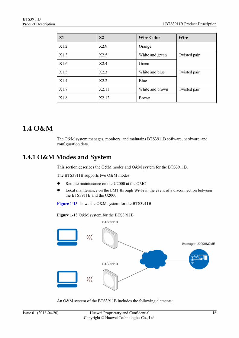
1.4 O&MThe O&M system manages, monitors, and maintains BTS3911B software, hardware, andconfiguration data.
1.4.1 O&M Modes and SystemThis section describes the O&M modes and O&M system for the BTS3911B.
The BTS3911B supports two O&M modes:
l Remote maintenance on the U2000 at the OMCl Local maintenance on the LMT through Wi-Fi in the event of a disconnection between
the BTS3911B and the U2000
Figure 1-13 shows the O&M system for the BTS3911B.
Figure 1-13 O&M system for the BTS3911B
An O&M system of the BTS3911B includes the following elements:
BTS3911BProduct Description 1 BTS3911B Product Description
Issue 01 (2018-04-20) Huawei Proprietary and ConfidentialCopyright © Huawei Technologies Co., Ltd.
16

l LMTUsed to locally manage a single base station, including status and alarm query, and PnPtracing. You can log in to the LMT over Wi-Fi.
l U2000Used to manage multiple base stations remotely.
l CMEUsed to configure and manage base station data.
1.4.2 O&M FunctionsA variety of O&M functions are available for the BTS3911B.
Configuration Management
Configuration management is used to configure network resources by using configurationdata for network devices. This function allows you to control the running status of networkdevices and is required during the entire network O&M cycle.
l During network deployment, configuration management is used to initializeconfiguration data, and install and set up network devices. BTS3911Bs support regionaldeployment and site deployment.– Regional deployment
BTS3911Bs in the same region share the common parameter settings, and automaticnetwork planning completes the specific parameter settings.
– Site deploymentThe CME can be used to deploy BTS3911Bs in scenarios applicable to operator-specific private networks, small-scale BTS3911B deployment, and where regionaldeployment is not supported.
l During network adjustment, optimization, or routine O&M, configuration management isused to do the following:– Configure parameters for new features.– Modify parameter settings for scenarios, such as network capacity expansion,
transmission adjustment, and wireless network performance optimization.– Monitor and modify network parameters.
Fault Management
The O&M system manages faults related to hardware, environment, software, transmission,cells, and services. Fault management involves the following functions:
l Fault detectionAllows viewing faults on the device panel and perform simple operations.
l Fault isolationPrevents faults from affecting the operational continuity of the BTS3911B.
l Self-healingMinimizes the impact of faults on services by lowering specifications or reestablishingcells.
BTS3911BProduct Description 1 BTS3911B Product Description
Issue 01 (2018-04-20) Huawei Proprietary and ConfidentialCopyright © Huawei Technologies Co., Ltd.
17

l Alarm correlationEnables BTS3911Bs to report only the root fault and the ultimate impact on services.
Performance Management
Performance management involves periodic performance measurement on the BTS3911B,and collection, storage, and reporting of measurement results
Tracing Management
Tracing management facilitates routine maintenance, commissioning, and troubleshooting bycollecting the following:
l Internal messagesl Messages exchanged over interfaces, signaling links, and UEs
Signaling messages are traced either on the U2000 or on the LMT.
l Tracing on the U2000– Message reporting
The BTS3911B reports signaling messages directly to the U2000.– File reporting
The BTS3911B saves signaling messages as a file and then reports the file to theU2000 periodically.
l Tracing on the LMT supports only message reporting.
Security Management
Security management implements user authentication and access control. It includes thefollowing functions:
l User account managementl Rights managementl Login managementl Identity authenticationl Operation authentication
Security control on the transmission channels between the BTS3911B and the U2000 supportsthe following:
l IPsecl Secure Socket Layer (SSL)l Public Key Infrastructure (PKI)l Datagram Transport Layer Security (DTLS)
Security management provides network- and user-specific security services. It provides thefollowing functions:
l EncryptionEncrypts important user information.
BTS3911BProduct Description 1 BTS3911B Product Description
Issue 01 (2018-04-20) Huawei Proprietary and ConfidentialCopyright © Huawei Technologies Co., Ltd.
18

l Authentication
Manages and authenticates user accounts.
l Access control
Controls user operations.
l Security protocol
Supports SSL.
Software Management
Software management involves the following functions:
l Software version management
Software versions can be queried and restored.
l Software version upgrade
BTS3911Bs can be remotely upgraded in batches. With the one-click remote upgradewizard provided by the U2000, you can:
– Perform health checks before and after upgrades.
– Download and activate software.
– Check the upgrade status and results.
BTS3911Bs support automatic configuration updates during upgrades. To perform anupgrade, follow the instructions on the upgrade wizard. To reduce the impact of upgradefailures, roll back the software version by running a single command.
l Patch management
Involves patch query, download, activation, deactivation, rollback, and removal.
Inventory Management
Inventory management involves the collection and reporting of BTS3911B inventoryinformation to manage network equipment assets at the OMC.
1.5 SpecificationsThis section describes the technical specifications and reliability of the BTS3911B.
1.5.1 Technical SpecificationsThis section provides BTS3911B technical specifications, including supported modes andfrequency bands, RF specifications, capacity specifications, output power and powerconsumption, Wi-Fi specifications, equipment specifications, environment specifications,standards compliance, and surge protection specifications.
Supported Modes and Frequency Bands
Table 1-9 lists the modes and frequency bands supported by a BTS3911B.
BTS3911BProduct Description 1 BTS3911B Product Description
Issue 01 (2018-04-20) Huawei Proprietary and ConfidentialCopyright © Huawei Technologies Co., Ltd.
19

Table 1-9 Modes and frequency bands supported by a BTS3911B
Scenario Mode FrequencyBand(MHz)
RXFrequencyBand(MHz)
TXFrequencyBand(MHz)
SupportedBandwidth (MHz)
IBW(MHz)
1800 MHz LTE(FDD)
LTE(FDD)
1800 1710 to1785
1805 to1880
5/10/15/20 20
2100 MHz LTE(FDD)
LTE(FDD)
2100 1920 to1980
2110 to2170
5/10/15/20 20
2100 MHzUMTS
UMTS 2100 1920 to1980
2110 to2170
5 20
2600 MHz LTE(FDD)
LTE(FDD)
2600 2500 to2570
2620 to2690
5/10/15/20 20
2100 MHz LTE(FDD)+2100MHz UMTS
LTE(FDD)
2100 1920 to1980
2110 to2170
5/10/15 20
UMTS 2100 1920 to1980
2110 to2170
5 20
1800 MHz LTE(FDD)+2100MHz LTE(FDD)
LTE(FDD)
1800 1710 to1785
1805 to1880
5/10/15/20 20
LTE(FDD)
2100 1920 to1980
2110 to2170
5/10/15/20 20
1800 MHz LTE(FDD)+2100MHz UMTS
LTE(FDD)
1800 1710 to1785
1805 to1880
5/10/15/20 20
UMTS 2100 1920 to1980
2110 to2170
5 20
2100 MHz LTE(FDD)+2600MHz LTE(FDD)
LTE(FDD)
2100 1920 to1980
2110 to2170
5/10/15/20 20
LTE(FDD)
2600 2500 to2570
2620 to2690
5/10/15/20 20
2100 MHzUMTS+2600MHz LTE(FDD)
UMTS 2100 1920 to1980
2110 to2170
5 20
LTE(FDD)
2600 2500 to2570
2620 to2690
5/10/15/20 20
AWS LTE(FDD)
LTE(FDD)
AWS 1710 to1755
2110 to2155
5/10/15/20 20
PCS LTE(FDD)
LTE(FDD)
PCS 1850 to1910
1930 to1990
5/10/15/20 20
AWS UMTS UMTS AWS 1710 to1755
2110 to2155
5 20
BTS3911BProduct Description 1 BTS3911B Product Description
Issue 01 (2018-04-20) Huawei Proprietary and ConfidentialCopyright © Huawei Technologies Co., Ltd.
20

Scenario Mode FrequencyBand(MHz)
RXFrequencyBand(MHz)
TXFrequencyBand(MHz)
SupportedBandwidth (MHz)
IBW(MHz)
PCS UMTS UMTS PCS 1850 to1910
1930 to1990
4.2/5 20
AWS LTE(FDD)+PCSLTE (FDD)
LTE(FDD)
AWS 1710 to1755
2110 to2155
5/10/15/20 20
LTE(FDD)
PCS 1850 to1910
1930 to1990
5/10/15/20 20
AWS LTE(FDD)+AWSUMTS
LTE(FDD)
AWS 1710 to1755
2110 to2155
5/10/15/20 20
UMTS AWS 1710 to1755
2110 to2155
5 20
PCS LTE(FDD)+PCSUMTS
LTE(FDD)
PCS 1850 to1910
1930 to1990
5/10/15/20 20
UMTS PCS 1850 to1910
1930 to1990
5 20
AWS LTE(FDD)+PCSUMTS
LTE(FDD)
AWS 1710 to1755
2110 to2155
5/10/15/20 20
UMTS PCS 1850 to1910
1930 to1990
4.2/5 20
RF SpecificationsThe UMTS receiver sensitivity is measured at the antenna connector under the conditionsrecommended in 3GPP TS 25.104:
l The channel rate is 12.2 kbit/s.l The bit error rate does not exceed 0.001.
The LTE receiver sensitivity is measured under the conditions recommended in annex A in3GPP TS 36.104:
l The channel bandwidth is 5 MHz.l The reference measurement channel is FRC A1-3 in annex A.1 (QPSK, R = 1/3, 25
RBs).
Table 1-10 describes the TX/RX channel and receiver sensitivity of a BTS3911B.
BTS3911BProduct Description 1 BTS3911B Product Description
Issue 01 (2018-04-20) Huawei Proprietary and ConfidentialCopyright © Huawei Technologies Co., Ltd.
21
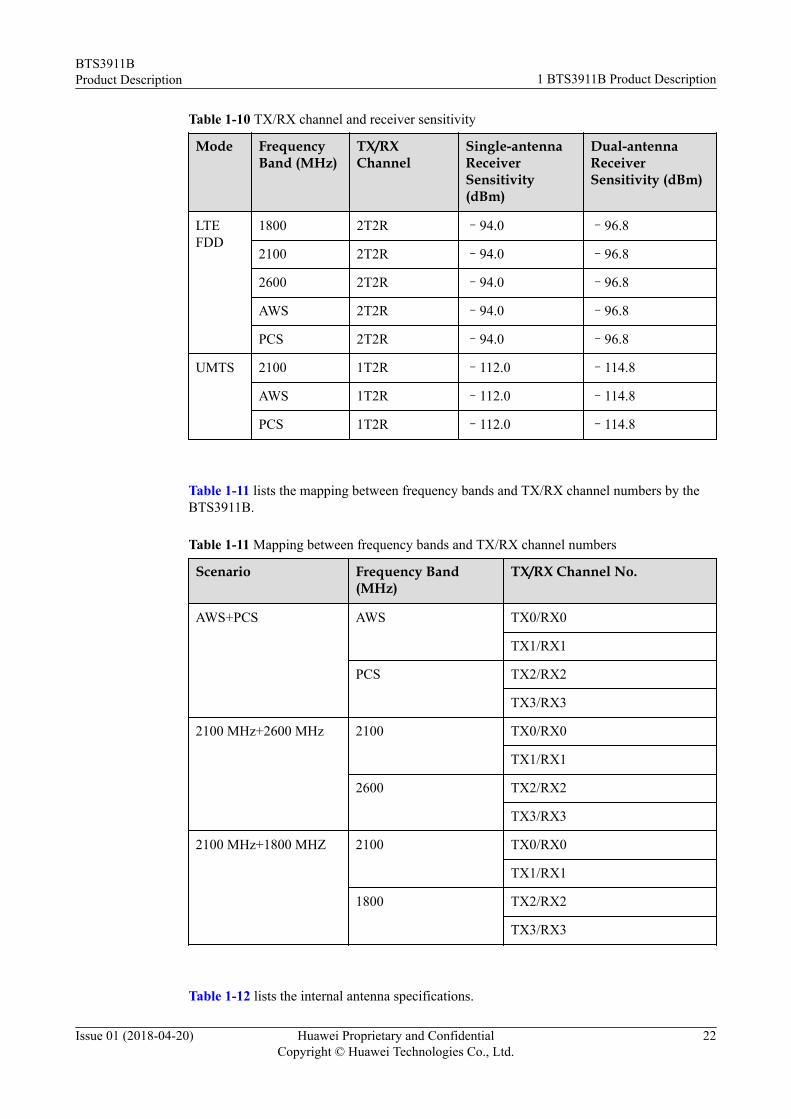
Table 1-10 TX/RX channel and receiver sensitivity
Mode FrequencyBand (MHz)
TX/RXChannel
Single-antennaReceiverSensitivity(dBm)
Dual-antennaReceiverSensitivity (dBm)
LTEFDD
1800 2T2R –94.0 –96.8
2100 2T2R –94.0 –96.8
2600 2T2R –94.0 –96.8
AWS 2T2R –94.0 –96.8
PCS 2T2R –94.0 –96.8
UMTS 2100 1T2R –112.0 –114.8
AWS 1T2R –112.0 –114.8
PCS 1T2R –112.0 –114.8
Table 1-11 lists the mapping between frequency bands and TX/RX channel numbers by theBTS3911B.
Table 1-11 Mapping between frequency bands and TX/RX channel numbers
Scenario Frequency Band(MHz)
TX/RX Channel No.
AWS+PCS AWS TX0/RX0
TX1/RX1
PCS TX2/RX2
TX3/RX3
2100 MHz+2600 MHz 2100 TX0/RX0
TX1/RX1
2600 TX2/RX2
TX3/RX3
2100 MHz+1800 MHZ 2100 TX0/RX0
TX1/RX1
1800 TX2/RX2
TX3/RX3
Table 1-12 lists the internal antenna specifications.
BTS3911BProduct Description 1 BTS3911B Product Description
Issue 01 (2018-04-20) Huawei Proprietary and ConfidentialCopyright © Huawei Technologies Co., Ltd.
22

Table 1-12 Internal antenna specifications
Frequency Band(MHz)
Gain (dBi) PolarizationMode
Directionality
1800 2 Linear Omnidirectional
2100 2 Linear Omnidirectional
2600 3 Linear Omnidirectional
AWS 2 Linear Omnidirectional
PCS 2 Linear Omnidirectional
Capacity Specifications
Table 1-13 Capacity specifications in LTE only mode
Item Specifications
Maximum number of cells per BTS3911B l Single-band: One 20 MHz celll Dual-band: Two 20 MHz cells
Maximum number of UEs inRRC_Connected mode
l For a cell: 192l For a BTS3911B: 384
Maximum throughput For a cell:l Downlink: 195 Mbit/sl Uplink: 71 Mbit/sFor a BTS3911B:l Downlink: 390 Mbit/sl Uplink: 142 Mbit/s
Maximum number of concurrent data radiobearers (DRBs) per UE
8
Maximum number of concurrent DRBs l For a cell: 576l For a BTS3911B: 1152
Table 1-14 Capacity specifications in UMTS only mode
Item Specifications
Maximum number of cells per BTS3911B One cell
Maximum number of CEs per BTS3911B l Downlink: 32 CEsl Uplink: 32 CEs
Maximum number of UEs per BTS3911B 32 HSPA UEs
BTS3911BProduct Description 1 BTS3911B Product Description
Issue 01 (2018-04-20) Huawei Proprietary and ConfidentialCopyright © Huawei Technologies Co., Ltd.
23

Item Specifications
Maximum throughput per BTS3911B l Downlink: 21 Mbit/sl Uplink: 5.76 Mbit/s
Table 1-15 Capacity specifications in UMTS+LTE mode
Item UMTS Specifications LTE Specifications
Maximum number of cellsper BTS3911B
One cell One 20 MHz cell
Maximum number of CEsper BTS3911B
l Downlink: 32 CEsl Uplink: 32 CEs
-
Maximum number of UEsper BTS3911B
32 HSPA UEs 192 UEs in RRC_Connectedmode
Maximum throughput perBTS3911B
l Downlink: 21 Mbit/sl Uplink: 5.76 Mbit/s
l Downlink: 195 Mbit/sl Uplink: 71 Mbit/s
Maximum number ofconcurrent DRBs per UE
- 8
Maximum number ofconcurrent DRBs
- 576
Output Power and Power Consumption
Table 1-16 Output power and power consumption
Maximum Output Power Power Consumption
l Single-band: 2 x 125 mWl Dual-band: 2 x 2 x 125 mW
l Single-band+Wi-Fi: 47 Wl Dual-band+Wi-Fi: 54 W
NOTE
l "Single-band+Wi-Fi" provides power consumption on a cellular band and a Wi-Fi band when thepower amplifier (PA) of the other cellular band is disabled for a dual-band BTS3911B.
l In the Maximum Output Power (W) column, AxB indicates that the BTS3911B is configured withA TX channels and the maximum output power per channel is B W. CxDxE indicates that aBTS3911B provides C frequency bands with D TX channels per band and E W output power perchannel.
l The supported power for a BTS3911B ranges from 12.5 mW to 125 mW. The static power class is10 dB. If the power class exceeds 10 dB, radio performance cannot be ensured and the reconfiguredpower must fall into the supported range.
l When the total distance between a dual-band+Wi-Fi BTS3911B and transmission device is 100 m,the maximum input power of a PSE injector is 70 W.
BTS3911BProduct Description 1 BTS3911B Product Description
Issue 01 (2018-04-20) Huawei Proprietary and ConfidentialCopyright © Huawei Technologies Co., Ltd.
24

Wi-Fi Specifications
Table 1-17 Wi-Fi specifications
Item Specifications
Supportedfrequencyband
l 2.4 GHz: 2.4000 GHz to 2.4835 GHzl 5 GHz: 5.15 GHz to 5.35 GHz, 5.470 GHz to 5.725 GHz, and 5.725
GHz to 5.850 GHz
Antenna gain l 2.4 GHz: 3 dBil 5 GHz: 7 dBi
TX power l 802.11n: 16 dBml 802.11ac: 14 dBm
EIRP l 2.4 GHz: 24 dBml 5 GHz: 28 dBm
Maximumthroughput
l 2.4 GHz: 450 Mbit/sl 5 GHz: 1300 Mbit/s
Standardscompliance
l 2.4 GHz: 802.11b/g/nl 5 GHz: 802.11a/n/ac
MIMO 3T3R
Maximumnumber ofassociatedUEs
256
Polarizationmode
Linear
Directionality Omnidirectional
NOTE
For a BTS3911B working at 2600 MHz, its 2.4 GHz Wi-Fi module cannot not use channel 12 or 13.
Transmission Port Specifications
Table 1-18 Transmission port specifications
Transmission Port Type Number of Ports
FE/GE electrical port 1
BTS3911BProduct Description 1 BTS3911B Product Description
Issue 01 (2018-04-20) Huawei Proprietary and ConfidentialCopyright © Huawei Technologies Co., Ltd.
25

Equipment Specifications
Table 1-19 Equipment specifications
Item Specifications
Dimensions (H x W xD)
200 mm x 200 mm x 55 mm (2.2 L)
Weight 2 kg (with internal antenna)
EOS 8 years
Availability 0.99999899
Environment Specifications
Table 1-20 Environment specifications
Item Specifications
Operating temperature –5°C to +40°C
Relative humidity 5% RH to 95% RH
Absolute humidity 1 to 30 g/m3
Altitude Functional from –60 m to 1800 mAble to work from 1800 m to 4000 m
Operating pressure 70 kPa to 106 kPa
Operating environment Storage environment: ETS 300 019-1-1 Class 1.2Transportation environment: ETS 300 019-1-2 Class 2.3Application environment: ETS 300 019-1-3 Class 3.2
IP rating IP20
Shockproof capability GR63 ZONE4 suitability requirements
Protection from damp,mold, and salt-spray fog
IEC60950
NOTE
It is recommended that the device be installed and used within one year after its delivery. Failure ratesincrease after one year if the device is not installed.
BTS3911BProduct Description 1 BTS3911B Product Description
Issue 01 (2018-04-20) Huawei Proprietary and ConfidentialCopyright © Huawei Technologies Co., Ltd.
26

Standards Compliance
Table 1-21 Standards compliance
Item Specifications
EMC l CISPR 22l EN 55022l EN 301 489-17l EN 301 489-23l CISPR 24l IEC 61000-4-2l IEC 61000-4-3l IEC 61000-4-4l IEC 61000-4-5l IEC 61000-4-6l IEC 61000-4-29l GB 9254l ETSI 301 489-1l VCCI V-3
3GPP l Release 99l Release 4l Release 5l Release 6l Release 7l Release 8l Release 9l Release 10
Environmental protectionstandard
RoHS
Surge protection standards l IEC 61000-4-5l YD 5098
Protection standards l IEC 61000-4-5l YD 5068-98l YD 5098
BTS3911BProduct Description 1 BTS3911B Product Description
Issue 01 (2018-04-20) Huawei Proprietary and ConfidentialCopyright © Huawei Technologies Co., Ltd.
27

Item Specifications
Safety standards l AS/NZS60950-1l AS/NZS60950-22l EN 60950-1l EN 60950-22l IEC 60950-1l IEC 60950-22l UL60950-1l UL60950-22
Environmental standards l IEC60068-2-2l ETSI EN300019-1-1l ETSI EN300019-1-2l ETSI EN300019-1-3l ETSI EN300019-2-1l ETSI EN300019-2-2l ETSI EN300019-2-3
ETL Conforms to UL STD.60950-1 CERTIFIED TO CSASTD.C22.2 NO.60950-1The following figure shows the identity of ETL:
Surge Protection Specifications for Ports
Table 1-22 Surge protection specifications for ports
Port Surge Protection Mode Surge ProtectionSpecifications
PoE Differential mode ±0.5 kV (1.2/50 μs)
Common mode ±2 kV (1.2/50 μs)
RGPS Differential mode ±0.5 kV (1.2/50 μs)
1.5.2 Typical Power ConfigurationThis section provides typical power configurations.
BTS3911BProduct Description 1 BTS3911B Product Description
Issue 01 (2018-04-20) Huawei Proprietary and ConfidentialCopyright © Huawei Technologies Co., Ltd.
28

A BTS3911B can work in UMTS only, LTE FDD only, or UMTS+LTE mode, where:
l A BTS3911B working in UMTS only mode can be configured with a maximum of onecarrier.
l A BTS3911B working in LTE FDD only mode can be configured with a maximum oftwo carriers with a maximum of one LTE carrier on one frequency band.
l A BTS3911B working in UMTS+LTE FDD mode can be configured with a maximum ofone UMTS carrier plus one LTE carrier.
Table 1-23 and Table 1-24 provide typical power configuration for the BTS3911B (LTEFDD, 1800 MHz/2100 MHz/2600 MHz/AWS/PCS).
Table 1-25 and Table 1-26 provide typical power configuration for the BTS3911B (UMTS,2100 MHz/2600 MHz/AWS).
Table 1-27 and Table 1-28 provide typical power configuration for the BTS3911B (UMTS,PCS).
Table 1-29 and Table 1-30 provide typical power configuration for the BTS3911B (UMTS+LTE, 2100 MHz/AWS/PCS).
Table 1-31 and Table 1-32 provide typical power configuration for the BTS3911B (LTE FDDPCS+LTE FDD AWS), BTS3911B (LTE FDD 2100 MHz+LTE FDD 2600 MHz)/(LTE FDD2100 MHz+LTE FDD 1800 MHz).
Table 1-33 and Table 1-34 provide typical power configuration for the BTS3911B (UMTSPCS+LTE FDD AWS).
Table 1-35 and Table 1-36 provide typical power configuration for the BTS3911B (UMTS2100 MHz+LTE FDD 2600 MHz)/(UMTS 2100 MHz+LTE FDD 1800 MHz).
Table 1-23 Typical power configuration for the BTS3911B (LTE FDD, 1800 MHz/2100MHz/2600 MHz/AWS/PCS)
Mode Number of LTEFDD Carriers
Output Power perLTE FDD Carrier(mW)
Supported LTEFDD CellBandwidth (MHz)
LTE FDD 1 (MIMO) 2x125 5/10/15/20
Table 1-24 Typical power configuration for BTS3911B PAs (LTE FDD, 1800 MHz/2100MHz/2600 MHz/AWS/PCS)
CarrierConfiguration
PA1 PA2
Total Numberof LTE FDDCarriers
Output Powerper LTE FDDCarrier (mW)
Total Numberof LTE FDDCarriers
Output Powerper LTE FDDCarrier (mW)
One LTE FDDcarrier (MIMO)
1 125 1 125
BTS3911BProduct Description 1 BTS3911B Product Description
Issue 01 (2018-04-20) Huawei Proprietary and ConfidentialCopyright © Huawei Technologies Co., Ltd.
29

Table 1-25 Typical power configuration for the BTS3911B (UMTS, 2100 MHz/2600 MHz/AWS)
Mode Number of UMTSCarriers
Output Power perUMTS Carrier (mW)
Supported UMTSCell Bandwidth(MHz)
UMTS 1 125 5
Table 1-26 Typical power configuration for BTS3911B PAs (UMTS, 2100 MHz/2600 MHz/AWS)
CarrierConfiguration
PA1 PA2
Total Numberof UMTSCarriers
Output Powerper UMTSCarrier (mW)
Total Numberof UMTSCarriers
Output Powerper UMTSCarrier (mW)
1 1 125 0 0
Table 1-27 Typical power configuration for the BTS3911B (UMTS, PCS)
Mode Number of UMTSCarriers
Output Power perUMTS Carrier (mW)
Supported UMTSCell Bandwidth(MHz)
UMTS 1 125 4.2/5
Table 1-28 Typical power configuration for BTS3911B PAs (UMTS, PCS)
CarrierConfiguration
PA1 PA2
Total Numberof UMTSCarriers
Output Powerper UMTSCarrier (mW)
Total Numberof UMTSCarriers
Output Powerper UMTSCarrier (mW)
1 1 125 0 0
BTS3911BProduct Description 1 BTS3911B Product Description
Issue 01 (2018-04-20) Huawei Proprietary and ConfidentialCopyright © Huawei Technologies Co., Ltd.
30

Table 1-29 Typical power configuration for the BTS3911B (UMTS+LTE, 2100 MHz/AWS/PCS)
Mode TotalNumberof UMTSCarriers
TotalNumberof LTEFDDCarriers
OutputPowerperUMTSCarrier(mW)
Supported UMTSCellBandwidth (MHz)
OutputPowerper LTEFDDCarrier(mW)
Supported LTEFDD CellBandwidth (MHz)
UMTS+LTEFDD
1 1 (MIMO) 50 5 2x50 5/10/15
Table 1-30 Typical power configuration for BTS3911B PAs (UMTS+LTE, 2100 MHz/AWS/PCS)
Carrier Configuration PA1 PA2
TotalNumberofUMTSCarriers
OutputPowerperUMTSCarrier(mW)
TotalNumberofLTEFDDCarriers
OutputPowerperLTEFDDCarrier(mW)
TotalNumber ofUMTSCarriers
OutputPower perUMTSCarrier(mW)
TotalNumber ofLTEFDDCarriers
OutputPowerperLTEFDDCarrier(mW)
One UMTS carrier+one LTE FDD carrier(MIMO)
1 50 1 50 0 0 1 50
Table 1-31 Typical power configuration for the BTS3911B (LTE FDD PCS+LTE FDDAWS)/(LTE FDD 2100 MHz+LTE FDD 2600 MHz)/(LTE FDD 2100 MHz+LTE FDD 1800MHz)
Mode TotalNumber ofLTE FDDCarriers onOneFrequencyBand
OutputPower perLTE FDDCarrier onOneFrequencyBand (mW)
TotalNumber ofLTE FDDCarriers onthe OtherFrequencyBand
OutputPower perLTE FDDCarrier onthe OtherFrequencyBand (mW)
SupportedLTE FDDCellBandwidth(MHz)
LTE FDD 1 (MIMO) 2x125 1 (MIMO) 2x125 5/10/15/20
BTS3911BProduct Description 1 BTS3911B Product Description
Issue 01 (2018-04-20) Huawei Proprietary and ConfidentialCopyright © Huawei Technologies Co., Ltd.
31

Table 1-32 Typical power configuration for BTS3911B PAs (LTE FDD PCS+LTE FDDAWS)/(LTE FDD 2100 MHz+LTE FDD 2600 MHz)/(LTE FDD 2100 MHz+LTE FDD 1800MHz)
Carrier Configuration PA1 (OneFrequencyBand)
PA2 (OneFrequencyBand)
PA1 (theOtherFrequencyBand)
PA2 (theOtherFrequencyBand)
TotalNumberofLTEFDDCarriers
OutputPowerperLTEFDDCarrier(mW)
TotalNumberofLTEFDDCarriers
OutputPower perLTEFDDCarrier(mW)
TotalNumberofLTEFDDCarriers
OutputPower perLTEFDDCarrier(mW)
TotalNumberofLTEFDDCarriers
OutputPower perLTEFDDCarrier(mW)
Two LTE FDD carriers(MIMO)
1 125 1 125 1 125 1 125
Table 1-33 Typical power configuration for the BTS3911B (UMTS PCS+LTE FDD AWS)
Mode TotalNumberof UMTSCarriers
TotalNumberof LTEFDDCarriers
OutputPowerperUMTSCarrier(mW)
Supported UMTSCellBandwidth (MHz)
OutputPowerper LTEFDDCarrier(mW)
Supported LTEFDD CellBandwidth (MHz)
UMTS+LTEFDD
1 1 (MIMO) 125 4.2/5 2x125 5/10/15/20
Table 1-34 Typical power configuration for BTS3911B PAs (UMTS PCS+LTE FDD AWS)
Carrier Configuration PCS PA1 PCS PA2 AWS PA1 AWS PA2
TotalNumberofUMTSCarriers
OutputPowerperUMTSCarrier(mW)
TotalNumberofUMTSCarriers
OutputPower perUMTSCarrier(mW)
TotalNumberofLTEFDDCarriers
OutputPower perLTEFDDCarrier(mW)
TotalNumberofLTEFDDCarriers
OutputPower perLTEFDDCarrier(mW)
BTS3911BProduct Description 1 BTS3911B Product Description
Issue 01 (2018-04-20) Huawei Proprietary and ConfidentialCopyright © Huawei Technologies Co., Ltd.
32

One UMTS carrier+oneLTE FDD carrier(MIMO)
1 125 0 0 1 125 1 125
Table 1-35 Typical power configuration for the BTS3911B (UMTS 2100 MHz+LTE FDD2600 MHz)/(UMTS 2100 MHz+LTE FDD 1800 MHz)
Mode TotalNumberof UMTSCarriers
TotalNumberof LTEFDDCarriers
OutputPowerperUMTSCarrier(mW)
Supported UMTSCellBandwidth (MHz)
OutputPowerper LTEFDDCarrier(mW)
Supported LTEFDD CellBandwidth (MHz)
UMTS+LTEFDD
1 1 (MIMO) 125 5 2x125 5/10/15/20
Table 1-36 Typical power configuration for BTS3911B PAs (UMTS 2100 MHz+LTE FDD2600 MHz)/(UMTS 2100 MHz+LTE FDD 1800 MHz)
Carrier Configuration 2100 MHzPA1
2100 MHzPA2
1800 MHz/2600 MHzPA1
1800 MHz/2600 MHzPA2
TotalNumberofUMTSCarriers
OutputPowerperUMTSCarrier(mW)
TotalNumberofUMTSCarriers
OutputPower perUMTSCarrier(mW)
TotalNumberofLTEFDDCarriers
OutputPower perLTEFDDCarrier(mW)
TotalNumberofLTEFDDCarriers
OutputPower perLTEFDDCarrier(mW)
One UMTS carrier+oneLTE FDD carrier(MIMO)
1 125 0 0 1 125 1 125
1.5.3 ReliabilityThis section describes hardware reliability and software reliability of a BTS3911B.
System ReliabilitySystem reliability is improved owing to features such as load sharing and configurationredundancy, as well as optimized fault detection and isolation technologies.
BTS3911BProduct Description 1 BTS3911B Product Description
Issue 01 (2018-04-20) Huawei Proprietary and ConfidentialCopyright © Huawei Technologies Co., Ltd.
33

l RedundancyRedundancy is supported by units, such as the power supply unit, and key files, such assoftware versions and configuration files.
l ReliabilityThe system automatically detects and diagnoses faults in the software, hardware, andenvironment, and reports alarms. Then the system automatically clears the faults usingself-healing measures. If the faults cannot be cleared, the faulty units will beautomatically isolated.
Hardware Reliabilityl Over-temperature protection
The BTS3911B reports an over-temperature alarm when its PA temperature is too highand performs either of the following:– If the temperature is higher than the threshold for a major alarm, the BTS3911B
automatically turns off the PA and stops providing services. This protects theBTS3911B from over-temperature damage.
– If the temperature is higher than the threshold for a minor alarm, the BTS3911Benables the temperature derating function. This ensures the services of admittedUEs and refuses the access requests of new UEs to prevent the temperature fromincreasing.
l Reliable power supplyThe BTS3911B uses the following techniques to achieve a reliable power supply:– Support for a wide-range of voltages as well as surge protection– Power failure protection for programs and data– Protection of power supply against overvoltage and overcurrent
l Surge protection designThe BTS3911B adopts surge protection for the PoE power port and RGPS clock port.
Software Reliabilityl Redundancy
To ensure normal operation of a BTS3911B when errors occur in important files or data,the BTS3911B provides the following redundancy functions:– Software version redundancy
The BTS3911B stores software versions, including the BootROM version, indifferent partitions to provide redundancy. If the active version is abnormal, theBTS3911B switches to the backup version.
– Configuration file redundancyThe BTS3911B stores configuration files in different partitions to provideredundancy. If the in-use file is damaged, the BTS3911B can continue workingproperly by loading the backup file.
l Error tolerance capabilityIf software errors occur, the self-healing capability prevents BTS3911Bs from crashing.The software error tolerance capability covers the following aspects:– Scheduled checks of key resources
BTS3911BProduct Description 1 BTS3911B Product Description
Issue 01 (2018-04-20) Huawei Proprietary and ConfidentialCopyright © Huawei Technologies Co., Ltd.
34

The BTS3911B checks software resource usage and generates related logs andalarms, allowing the BTS3911B to release resources.
– Task monitoringThe BTS3911B monitors the running status of every task for errors and faults. If anerror or fault is detected, an alarm is reported and self-healing measures are taken torestore the task.
– Data checkThe BTS3911B checks data consistency when scheduled or triggered by events. Itcan selectively or preferentially restore data consistency. In addition, the BTS3911Bgenerates related logs and alarms.
– WatchdogIf an error occurs in a BTS3911B, the BTS3911B detects the error using thesoftware and hardware watchdogs and automatically restarts.
BTS3911BProduct Description 1 BTS3911B Product Description
Issue 01 (2018-04-20) Huawei Proprietary and ConfidentialCopyright © Huawei Technologies Co., Ltd.
35