product brochure superpile - fiberglass … · for additional information about cpi composite...
TRANSCRIPT

©2014 Creative Pultrusions Printed in the USA CPM234-1213.1CDLR: August 11, 2015
PLEASE SCAN WITH PHONE
For additional information about CPI composite piling products, or to learn how to lower your costs while increasing performance, contact a technical representative at
888-CPI-PULL (274-7855), or visit our website at www.creativepultrusions.com.
SUPERPILE® FIBERGLASS REINFORCED POLYMER (FRP) PIPE PILES
PRODUCT BROCHURE
Creative Pultrusions, Inc. reserves the right to edit and modify literature, please consult the web site for the most current version of this document.
www.creativepultrusions.comPhone 814.839.4186 • Fax 814.839.4276 • Toll Free 888.CPI.PULL
214 Industrial Lane, Alum Bank, PA 15521

PROVIDING LEADERSHIP IN FRP PIPE PILE TECHNOLOGY
1.
Creative Pultrusions, Inc. (CPI) is the world leader in pultrusion manufacturing. Our commitment to continuous process and product improvement has transformed CPI into a world-renowned pultruder specializing in custom profiles while utilizing high-performance resins and our proprietary high-pressure injection pultrusion technology.
As the world’s most innovative leader in the FRP pultrusion industry, over the last two decades, we’ve developed structural systems that out perform and outlast structures built with traditional materials of construction. CPI has continued to build upon their reputation by introducing a pipe pile product line known as SUPERPILE®. Developed to provide superior performance in harsh marine environments, SUPERPILE® has been developed to drive faster and last longer than traditional piles.
WHAT IS PULTRUSION?Pultrusion is a continuous manufacturing process utilized to make composite profiles with constant cross-sections whereby reinforcements, in the form of roving and mats, are saturated with resin and guided into a heated die. The resin undergoes a curing process known as polymerization. The once resin saturated reinforcements exit the die in a solid state and in the form of the cross section of the die. The pultrusion process requires little labor and is ideal for mass production of constant cross section profiles.
CPI PIPE PILES
The SUPERPILE® product line was developed based on what owners, end users, engineers and contractors value in a pipe pile.
• Longevity - Significant Reductions of Future Capital Expenditures • Maintenance - Significant Reductions of Future Maintenance Expenditures • Aesthetics - No Rust Marks, Spalling, Rotting or Section Loss • Green - Low Embodied Energy • Environmentally Friendly - Will Not Leach Dangerous Pesticides, Antifungal or Preservatives into the Environment
• Engineered Product - Unlike Wood, FRP is an Engineered Product with a Low Coefficient of Variation (COV) • High Strength - Pound for Pound Stronger than Steel, Concrete and Wood • Low Modulus of Elasticity - Dissipates Vessel Impact Energy • Versatile - Can Be Used as a Foundation Bearing, Dock or Fender Pile • Reliable - Design Values Are Based on a 95% Confidence Value • Design - Can Be Designed Based on Load and Resistance Factor Design (LRFD) or Allowable Stress Design (ASD) • Factory Made - Manufactured in an Environmentally Controlled Complex to Stringent Quality Assurance (QA) Standards
• Significant Shipping Savings • Drills and Cuts 2x Faster Than Thermoplastic Polymer Piles • Driven with Standard Pile Driving Equipment • Lightweight - 1/10th the Weight of a Concrete Pile and 1/4th the Weight of Steel • Field Drillable • Ease of Fabrication with Traditional Construction Tools
WHAT DO END USERS VALUE IN SUPERPILE®?
FASTEST DRIVEN& LONGEST LASTINGFASTEST DRIVEN& LONGEST LASTING
WHAT DO OWNERS VALUE IN SUPERPILE®?
WHAT DO ENGINEERS VALUE IN SUPERPILE®?
WHAT DO CONTRACTORS VALUE IN SUPERPILE®?
• Functionality - Performs as Designed and Intended• Aesthetics - Professional Look• Performance - Protects Your Boat and Structures

2. 3
All composite pipe piles are manufactured with electrical grade E-glass reinforcements in the form of unidirectional roving, Continuous Filament Mat (CFM) and stitched fabric mats. The combination of fiber reinforcements have been engineered for optimal bending and crush strength, as well as superior stiffness. All E-glass reinforcements meet a minimum tensile strength of 290 ksi per ASTM D2343.
3. FIBERGLASS REINFORCEMENTS
3.
CPI's composite pipe piles are shipped standard with two layers of Ultra Violet (UV) protection. First, CPI adds light stabilizers to each pile. The light stabilizers are mixed into the thermosetresin, prior to production, and function as long term thermal and light stability promoters. Second, the composite pipe piles are encompassed with a 10 mil polyester surfacing veil. The 10 mil veilcreates a resin rich surface and protects the glass reinforcements from fiber blooming. Additional UV and or abrasion barriers are available.
1. ADVANCED UV PROTECTION
The pipe piles are pultruded with high performance Vinyl Ester (VE) and Polyurethane resins. The octagonal pipe piles are manufactured with VE resin for its superior toughness and fatigue strength, VE resins are ideal for long term performance in harsh marine environments. The round pipe piles are manufactured standard with SUPURTUF™ Polyurethane resin. Polyurethane resins provide all of the performance of VE resins in addition to optimal strength, toughness and impact resistance. When it comes to high strength, toughness and impact properties, nothing outperforms SUPURTUF™ Polyurethane.
2. RESIN/MATRIX
1.
2.
“I have researched, tested and installed composite systems related to civil infrastructure over my entire career. I was astonished at the high strength and modulus values achieved with the polyurethane pipe piles manufactured by Creative Pultrusions, Inc. I expect that the US infrastructure will benefit greatly from this tubular pile technology.”
~ Hota GangaRao, PhD, P.E., F. ASCE West Virginia University
SUPERPILE® has undergone extensive testing at CPI, West Virginia University’s Constructed Facility Center and in the field. Tests that have been conducted: full section to failure, connection, compression, Pile Dynamic Analysis (PDA) and fatigue.
PILE TESTING
PILE CONSTRUCTIONSUPERPILE® Composite Pipe Pile is manufactured with electrical grade fiberglass and high impact, high strength polyurethane resin. The combination of the advanced resin and high strength glass produces a superior strength, highly corrosion resistant pipe pile.
PDA Analysis, Virginia
PDA Testing, Virginia
Full Section Pipe Pile Testing, West Virginia University

4.
Contractors all agree that the hollow SUPERPILE® drives twice as fast as solid wood, concrete and thermoplastic piles.
FASTEST DRIVENLong term durability projections predict a 75+ year service life.
LONGEST LASTINGHigh strength, low modulus equates to very high energy absorption capacities when compared to wood, steel and concrete.
ENERGY ABSORPTION
5.
EASE OF FABRICATIONCan be field drilled and cut in seconds.
NO LEACHING OF PRESERVATIVES, FUNGICIDES OR INSECTICIDESEnvironmentally friendly, the SUPERPILE® is inert, unlike wood that leaches dangerous chemicals into the environment.
ENGINEERED SOLUTIONDesigned specifically for the piling market and manufactured in a production environment.
The graphs demonstrate a comparison of polyester, VE and Polyurethane resins. The fiber architecture is the same, only the resin type has been modified. The chart clearly demonstrates the strength advantage of VE and SUPURTUF™ Polyurethane resins over that of polyester composites.
Polyester
Vinyl Ester
Polyurethane
WHY SHOULD YOU BUY & SPECIFY CPI PIPE PILES?

• UNAFFECTED BY MARINE BORERS Will not succumb to aquatic mollusks or crustaceans.
• LIGHTWEIGHT Significantly lighter than steel, concrete and wood piles.
• SAFETY Very low electrical conductivity, ideal for working around power lines.
6. 7.
• WILL NOT ROT Inert to fungi or microbial attack.
• GREEN Low embodied energy.
~Rich Walters R.A. Walters & Sons
~Mike EddeDutra Construction
WHAT ARE OWNERS AND CONTRACTORS SAYING ABOUT SUPERPILE®?
~Brad Gribble Crofton Industries
San Francisco West Harbor Renovation Project December 2011 (Phase 1), San Francisco, California
Fender Rehabilitation Route 3 Over Piankatank River, Virginia
Margate Bridge Installation, Margate New Jersey
“When our Margate Bridge wooden fender system succumbed to the years of wear and tear in a hostile environment, we knew it was time to invest in a new fender system. We chose to specify the latest in fender technology and go with Creative Pultrusion’s SUPERPILE. The piles were manufactured to spec. and delivered on time. The robust piles will protect our bridge foundations for many years without leaching any chemicals into our waterways. The piles made sense from a business and environmental standpoint, making the decision to procure the piles easy.”
“Upon award of the bid, Crofton knew that choosing the right supplier for the FRP piles was critical in order to get value engineering proposal approval by the project start date. Creative was the best choice since they have done extensive testing, are listed on multiple state’s Qualified Products Lists and have the engineering support to assist in securing this approval.
Creative addressed all material related questions and concerns brought about by the Engineer of Record and VADOT engineering. In fact, they provided piles so that a PDA could be performed on the 16” dia. FRP SUPERPILE. The PDA eliminated all concerns and questions that Crofton and the Engineering firm had with regards to installation and connection details.
Not only did Creative supply a quality product at a fair price, they stood behind us through the entire project. The engineering team at CPI made my life easier and saved Crofton money in the process.”
~David GoddardOle Hansen and Sons, Inc.
“Creative Pultrusions manufactured and supplied fifty-two FRP SUPERPILES to me through Lee Composites. The piles were supplied to specification and arrived on time. The piles were of high quality and drove twice as fast as a solid pile. The 80’ piles were lightweight and easy to handle. Given that the piles will not rot, rust or corrode, I anticipate driving many more SUPERPILES in the future. In fact, I see no reason not to use them!”
"Creative Pultrusions manufactured 190 SUPERPILES that were supplied by Lee Composites to Dutra Construction. The SUPERPILES replaced deteriorating creosote treated wood guide piles for the San Francisco Marina West Harbor Renovation Project. These piles are used as a fender by boats navigating in and out of their slips. The SUPERPILES are both aesthetically pleasing and have superior functionality to the treated wood piles. In addition, they are more environmentally friendly than their wood counterparts. They were installed very easily with a drop hammer and met all of our expectations. We expect these piles to stand the test of time by offering many years of maintenance free service. We expect to see a lot more of the SUPERPILES on future projects."
• NON-POLLUTING Accepted by NJDEP as non-polluting material for water and land use.

8. 9.
MECHANICAL & PHYSICAL PROPERTIESPIPE PILESThe mechanical and physical data detailed herein is provided for the structural engineer. The mechanical data is published in terms of average and characteristic values. The characteristic values were derived per the requirements as set forth in ASTM D7290 Standard Practice for Evaluating Material Property Characteristic Values for Polymeric Composites for Civil Engineering Structural Applications. The characteristic value is defined as a statistically-based material property representing the 80% lower confidence bound on the 5th-percentile value of a specified population. The characteristic value accounts for statistical uncertainty due to a finite sample size. The characteristic value is the reference strength.
In terms of Load and Resistance Factor Design (LRFD) design, the reference strength shall be adjusted for end use conditions by applying the applicable adjustment factors to establish the nominal resistance strength. The design strength shall include the nominal resistance, adjusted for end-
PIPE PILESMECHANICAL & PHYSICAL PROPERTIES
1The crush strength value is based on full section testing. The strength value was recorded at the first audible sound and change in the load deflection curve. The ultimate capacity is approximately 60% higher and is defined as the highest recorded load documented during the crush strength test. 2Characteristic data is unavailable due to the number of tests required. A minimum of 10 tests are required to generate the ASTM D7290 characteristic values.
use conditions, a resistance factor and time effect factor. The reference strength and stiffness shall be multiplied by .85 and .95 respectively to establish the nominal strength and stiffness for installations in sea and fresh water. A time effect factor of 0.4 shall be applied for full design permanent loads that will act during the service life of the structure. Resistant factors shall be established as set forth in the LRFD of Pultruded Fiber Reinforced Polymer (FRP) Structures Pre-Standard. Serviceability shall be checked based on the adjusted average full section modulus of elasticity as established per ASTM D6109.
In terms of Allowable Stress Design (ASD), the pultrusion industry uses a 3.0 safety factor for compression members, 2.5 for flexural members, 3.0 for connections and 3.0 for shear. The characteristic reference strength shall be used for strength and the average E-modulus shall be used for serviceability calculations.
SUPERPILE® Mechanical Properties Round FRP Pipe Pile TU455 Polyurethane 12"x3/8" Metric (305mm x 9.52mm)
Round FRP Pipe Pile TU450 Polyurethane 12"x1/2" Metric (305mm x 12.7mm)
Round FRP Pipe Pile TU460 Polyurethane 16"x1/2" Metric (406mm x 12.7mm)
Average Flexural Strength per ASTM D6109 psi (Mpa) 52,000 (359) 69,658 (480) 57,270 (395)
Characteristic Flexural Strength per ASTM D6109 psi (Mpa)2 ***** ***** 56,111 (387) 49,840 (344)
Average Compression Strength per ASTM D6109 psi (Mpa) 52,000 (359) 69,658 (480) 57,270 (395)
Characteristic Compression Strength per ASTM D6109 psi (Mpa)2 ***** ***** 56,111 (387) 49,840 (344)
Average In-Plane Shear Strength psi (Mpa) 15,605 (108) 16,039 (111) 17,170 (118)
Characteristic In-Plane Shear Strength psi (Mpa) 13,212 (91) 13,713 (95) 14,936 (103)
Average Shear Capacity lbs (Kg) 106,894 (48,486) 145,153 (65,840) 208,616 (94,626)
Characteristic Shear Capacity lbs (Kg) 90,502 (41,051) 124,103 (56,292) 181,472 (82,314)
Average Torque Strength lb-ft (kN▪m) 103,519 (140) 138,829 (188) 269,987 (366)
Characteristic Torque Strength lb-ft (kN▪m) 87,644 (119) 118,696 (161) 234,859 (318)
Average Axial Compression Strength psi (Mpa) 52,000 (359) 69,658 (480) 57,270 (395)
Characteristic Axial Compression Strength psi (Mpa)2 ***** ***** 56,111 (387) 49,840 (344)
Average Axial Compression Capacity (Short Column) lb (kg) 712,400 (323,139) 1,260,810 (571,894) 1,391,661 (631,247)
Characteristic Axial Compression Capacity (Short Column) lb (kg)2 ***** ***** 1,015,609 (460,673) 1,211,112 (549,351)
Average Modulus of Elasticity per ASTM D6109 psi (Gpa) 5.26E+06 (36.3) 5.91E+06 (40.7) 5.99E+06 (41.3)
Bending Stiffness (EI) per ASTM D6109 lbs▪in2 (kg▪mm2) 1.22E+09 (3.57E+11) 1.77E+09 (5.17E+11) 4.38E+09 (1.28E+12)
Average Moment Capacity per ASTM D6109 kip-ft (kN▪m) 167 (227) 289 (392) 437 (592)
SUPERPILE® Mechanical Properties Round FRP Pipe Pile TU455 Polyurethane 12"x3/8" Metric (305mm x 9.52mm)
Round FRP Pipe Pile TU450 Polyurethane 12"x1/2" Metric (305mm x 12.7mm)
Round FRP Pipe Pile TU460 Polyurethane 16"x1/2" Metric (406mm x1 2.7mm)
Characteristic Moment Capacity per ASTM D6109 kip-ft (kN▪m)2 ***** ***** 233 (316) 380 (515)
Average Energy Absorption kip-in (kN▪m) 341 (39) 643 (73) 829 (94)
Characteristic Energy Absorption kip-in (kN▪m)2 ***** ***** 405 (46) 603 (68)
Average Pin Bearing Strength Crosswise psi (Mpa) 19,823 (137) 21,676 (149) 23,666 (163)
Characteristic Pin Bearing Strength Crosswise psi (Mpa) 12,447 (86) 12,546 (87) 20,771 (143)
Average Pin Bearing Strength Lengthwise psi (Mpa) 30,793 (212) 30,149 (208) 27,788 (192)
Characteristic Pin Bearing Strength Lengthwise psi (Mpa) 18,053 (125) 25,132 (173) 19,217 (133)
Average Pile Crush Strength lb (kg) (based on a 9" wide load path)1 10,600 (4,808) 17,970 (8,151) 16,600 (7,530)
Characteristic Pile Crush Strength lb (kg) (based on a 9" wide load path)1 8,060 (3,656) 13,782 (6,251) 11,667 (5,292)
Average Crush Strength, with FRP Insert, lb (kg) (based on a 9" wide load path)1,2 ***** ***** 73,780 (33,466) 44,213 (20,055)
Characteristic Crush Strength, with FRP Insert, lb (kg) (based on a 9" wide load path)1,2 ***** ***** 51,370 (23,301) ***** *****
Average Washer Pull Through Strength lb (kg) using a 6"x1/2" square/radius washer 26,084 (11,832) 30,686 (13,919) 27,582 (12,511)
Characteristic Washer Pull Through Strength lb (kg) using a 6"x1/2" square/radius washer 22,107 (10,028) 26,815 (12,163) 25,103 (11,387)
Average Washer Pull Through Strength lb (kg) using a 6"x3/8" square/radius washer 18,893 (8,570) 25,205 (11,433) 18,878 (8,563)
Characteristic Washer Pull Through Strength lb (kg) using a 6"x3/8" square/radius washer 13,977 (6,340) 22,420 (10,170) 13,521 (6,133)
Allowable torque permitted on a bolted connection with a 6" radius washer lb-ft (N▪m) 50 (68) 50 (68) 50 (68)
SUPERPILE® Physical Properties Round FRP Pipe Pile TU455 Polyurethane 12"x3/8" Metric (305mm x 9.52mm)
Round FRP Pipe Pile TU450 Polyurethane 12"x1/2" Metric (305mm x 12.7mm)
Round FRP Pipe Pile TU460 Polyurethane 16"x1/2" Metric (406mm x 12.7mm)
Diameter in (cm) 12 (30.48) 12 (30.48) 16 (40.64)
Wall thickness in (mm) 0.375 (9.5) 0.5 (12.7) 0.5 (12.7)
Moment of Inertia in4 (cm4) 232 (9,657) 299 (12,445) 732 (30,468)
Section Modulus in3 (cm3) 38.6 (633) 49.8 (816) 91.5 (1,499)
Radius of Gyration in (mm) 4.11 (104) 4.07 (103) 5.48 (139)
Weight lb/ft (Kg/m) 12.6 (18.8) 16.9 (25.1) 22.6 (33.6)
Coefficient of Thermal Expansion (CTE) Lengthwise in/in/°F (mm/mm/°C)
5.00E-06 (9.00E-06) 5.00E-06 (9.00E-06) 5.00E-06 (9.00E-06)
Water Absorption ASTM D570 0.15% (24hrs)
0.15% (24hrs)
0.15% (24hrs)
0.15% (24hrs)
0.15% (24hrs)
0.15% (24hrs)
Fiber Volume Fraction % ≥50% ≥50% ≥50% ≥50% ≥50% ≥50%
Cross Sectional Area in2 (cm2) 13.7 (88) 18.1 (116.8) 24.3 (156.8)
Surface Area ft2/ft (m2/m) 3.14 (0.96) 3.14 (0.96) 4.19 (1.28)

10. 11.
MECHANICAL & PHYSICAL PROPERTIESOCTAGONAL PILES
Octagonal Pile Mechanical PropertiesOctagonal Pile
8"x.25" Series II CP076(203mm x 6.35mm)
Octagonal Pile10"x.25"Series II CP074
(254mm x 6.35mm)
Octagonal Pile10"x.275" Series III CP210
(254mm x 6.98mm)
Average Flexural Strength per ASTM D1036 psi (Mpa) 49,173 (339) 43,832 (302) 43,893 (303)
5% LEL Flexural Strength per ASTM D1036 psi (Mpa)1 46,999 (324) 41,374 (285) 42,076 (290)
Average Compression Strength per ASTM D1036 psi (Mpa) 49,173 (339) 43,832 (302) 43,893 (303)
5% LEL Compression Strength per ASTM D1036 psi Mpa)1 46,999 (324) 41,374 (285) 42,076 (290)
Average In-Plane Shear Strength psi (Mpa) 12,554 (87) 12,706 (88) 12,866 (89)
Characteristic In-Plane Shear Strength psi (Mpa) 10,940 (75) 10,101 (70) 11,616 (80)
Average Shear Capacity lbs (Kg) 48,458 (21,980) 68,359 (31,007) 86,649 (39,304)
Characteristic Shear Capacity lbs (Kg) 42,230 (19,155) 54,344 (24,650) 78,237 (35,488)
Average Torque Strength lb-ft (kN▪m) 24,675 (33) 41,166 (56) 45,621 (62)
Characteristic Torque Strength lb-ft (kN▪m) 21,504 (29) 32,726 (44) 41,191 (56)
Average Axial Compression Strength psi (Mpa) 49,173 (339) 43,832 (302) 43,893 (303)
5% LEL Axial Compression Strength psi (Mpa)1 46,999 (324) 41,374 (285) 42,076 (290)
Average Axial Compression Capacity (Short Column) lb (kg) 379,617 (172,191) 471,634 (213,930) 591,245 (268,184)
5% LEL Axial Compression Capacity (Short Column) lb (kg)1 362,832 (164,578) 445,184 (201,932) 566,764 (257,080)
Average Modulus of Elasticity per ASTM D1036 psi (Gpa) 4.30E+06 (29.6) 4.00E+06 (27.6) 3.70E+06 (25.5)
Bending Stiffness (EI) per ASTM 1036 lbs▪in2 (kg▪mm2) 2.62E+08 (7.67E+10) 5.58E+08 (1.63E+11) 6.35E+08 (1.86E+11)
Average Moment Capacity per ASTM D1036 kip-ft (kN▪m) 62 (85) 100 (136) 123 (167)
5% LEL Moment Capacity per ASTM D1036 kip-ft (kN▪m)1 60 (81) 94 (128) 118 (160)
Average Pin Bearing Strength Crosswise psi (Mpa) 15,357 (106) 11,562 (80) 11,280 (78)
Characteristic Pin Bearing Strength Crosswise psi (Mpa) 8,131 (56) 5,839 (40) 5,453 (38)
Octagonal Pile Physical PropertiesOctagonal Pile
8"x.25" Series II CP076(203mm x 6.35mm)
Octagonal Pile10"x.25"Series II CP074
(254mm x 6.35mm)
Octagonal Pile10"x.275" Series III CP210
(254mm x 6.98mm)
Diameter in (cm) 8 (20.32) 10.2 (25.91) 10.2 (25.91)
Wall thickness in (mm) 0.25 (6.4) 0.25 (6.4) 0.275 (7.0)
Moment of Inertia in4 (cm4) 60.87 (2,534) 139.69 (5,814) 171.57 (7,141)
Section Modulus in3 (cm3) 15.22 (249) 27.39 (449) 33.64 (551)
Radius of Gyration in (mm) 2.81 (71) 3.60 (91) 11.05 (281)
Weight lb/ft (Kg/m) 6.33 (9) 8.82 (13.1) 11.05 (16.4)
Coefficient of Thermal Expansion (CTE) Lengthwise in/in/°F (mm/mm/°C)
5.00E-06 (9.00E-06) 5.00E-06 (9.00E-06) 5.00E-06 (9.00E-06)
Water Absorption ASTM D570 0.60% (24hrs)
0.60% (24hrs)
0.60% (24hrs)
0.60% (24hrs)
0.60% (24hrs) 0.60% (24hrs)
Fiber Volume Fraction % ≥50% ≥50% ≥50% ≥50% ≥50% ≥50%
Cross Sectional Area in2 (cm2) 7.72 (50) 10.76 (69.4) 13.47 (86.9)
Surface Area ft2/ft (m2/m) 2.20 (0.67) 2.80 (0.85) 2.80 (0.85)
Octagonal Pile Fire PropertiesOctagonal Pile
8"x.25" Series II CP076(203mm x 6.35mm)
Octagonal Pile10"x.25"Series II CP074
(254mm x 6.35mm)
Octagonal Pile10"x.275" Series III CP210
(254mm x 6.98mm)
Flame Rating (UL 94) V0 Self Extinguishing V0 Self Extinguishing V0 Self Extinguishing
Flame Spread ASTM E-84 Class A 25 or less Class A 25 or less Class A 25 or less
Octagonal Pile Electrical PropertiesOctagonal Pile
8"x.25" Series II CP076(203mm x 6.35mm)
Octagonal Pile10"x.25"Series II CP074
(254mm x 6.35mm)
Octagonal Pile10"x.275" Series III CP210
254mm x 6.98mm)
ASTM F711 (100 kVAC per foot - 5 minutes dry) Passed Passed Passed
IEEE978 (75 kVAC per foot - 1 minute wet) Passed Passed Passed
MECHANICAL & PHYSICAL PROPERTIESOCTAGONAL PILES
The mechanical and physical data detailed herein is provided for the structural engineer. The mechanical data is published in terms of average value and either characteristic or 5% Lower Exclusion Limit (LEL) values. The characteristic values were derived per the requirements as set forth in ASTM D7290 Standard Practice for Evaluating Material Property Characteristic Values for Polymeric Composites for Civil Engineering Structural Applications. The characteristic value is defined as a statistically-based material property representing the 80% lower confidence bound on the 5th-percentile value of a specified population. In instances where sufficient data was not available to calculate the characteristic value, a 5% LEL was calculated. The 5% LEL, like the characteristic value, is the 5th-percentile value, however it is somewhat less conservative in that it does not account for the 80% lower confidence bound. The values are listed to account for statistical uncertainty due to a finite sample size. These statistically reduced values should be used as the reference strength.
In terms of Load and Resistance Factor Design (LRFD) design, the reference strength shall be
Octagonal Pile Mechanical PropertiesOctagonal Pile
8"x.25" Series II CP076(203mm x 6.35mm)
Octagonal Pile10"x.25"Series II CP074
(254mm x 6.35mm)
Octagonal Pile10"x.275" Series III CP210
(254mm x 6.98mm)Average Pin Bearing Strength Lengthwise psi (Mpa) 27,263 (188) 28,223 (195) 27,132 (187)
Characteristic Pin Bearing Strength Lengthwise psi (Mpa) 16,679 (115) 21,029 (145) 12,867 (89)
Average Washer Pull Through Strength lb kg) using a 4"x3/8" square washer 13,697 (6,213) 14,698 (6,667) 14,571 (6,609)
Characteristic Washer Pull Through Strength lb (kg) using a 4"x3/8" square washer 10,705 (4,856) 11,916 (5,405) 11,798 (5,351)
Allowable torque permitted on a bolted connection with a 4"x3/8" square washer lb-ft (N▪m) 50 (68) 50 (68) 50 (68)
Notes:15% Lower Exclusion Limit (LEL) was used as a statistical knockdown in instances where the sufficient number of data points was not available to calculate the characteristic value. 2All connection testing was conducted utilizing 3/4" hardware.
The Mechanical and Physical Property Charts for the Octagonal piles have been developed based on extensive third party and in house testing.
adjusted for end use conditions by applying the applicable adjustment factors to establish the nominal resistance strength. The design strength shall include the nominal resistance, adjusted for end-use conditions, a resistance factor and time effect factor. The reference strength and stiffness shall be multiplied by .85 and .95 respectively to establish the nominal strength and stiffness for installations in sea and fresh water. A time effect factor of 0.4 shall be applied for full design permanent loads that will act during the service life of the structure. Resistant factors shall be established as set forth in the LRFD of Pultruded Fiber Reinforced Polymer (FRP) Structures Pre-Standard. Serviceability shall be checked based on the adjusted average full section modulus of elasticity as established per ASTM D1036.
In terms of Allowable Stress Design (ASD), the pultrusion industry uses a 3.0 safety factor for compression members, 2.5 for flexural members, 3.0 for connections, and 3.0 for shear. The reference strength shall be used for strength and the average modulus shall be used for serviceability calculations.
12.
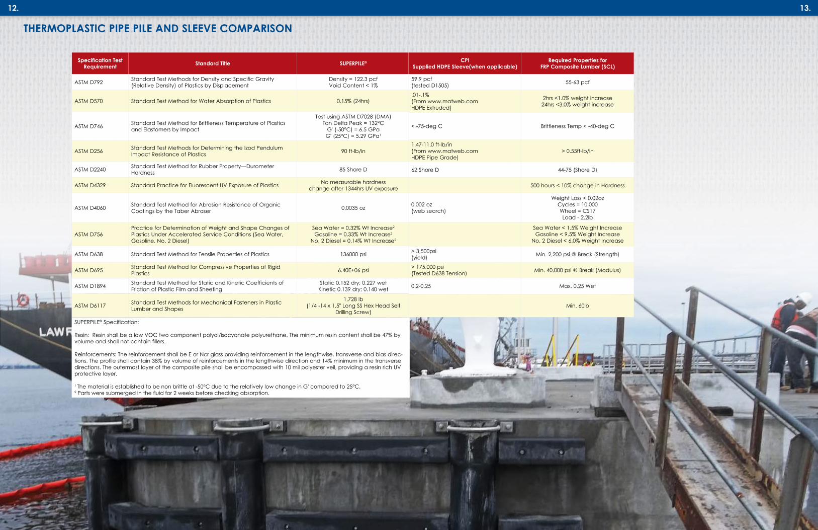
THERMOPLASTIC PIPE PILE AND SLEEVE COMPARISON
13.
Specification Test Requirement Standard Title SUPERPILE®
ASTM D792 Standard Test Methods for Density and Specific Gravity (Relative Density) of Plastics by Displacement
Density = 122.3 pcf Void Content < 1%
ASTM D570 Standard Test Method for Water Absorption of Plastics 0.15% (24hrs)
ASTM D746 Standard Test Method for Brittleness Temperature of Plastics and Elastomers by Impact
Test using ASTM D7028 (DMA) Tan Delta Peak = 132°C
G' (-50°C) = 6.5 GPa G' (25°C) = 5.29 GPa1
ASTM D256 Standard Test Methods for Determining the Izod Pendulum Impact Resistance of Plastics 90 ft-lb/in
ASTM D2240 Standard Test Method for Rubber Property—Durometer Hardness 85 Shore D
ASTM D4329 Standard Practice for Fluorescent UV Exposure of Plastics No measurable hardness change after 1344hrs UV exposure
ASTM D4060 Standard Test Method for Abrasion Resistance of Organic Coatings by the Taber Abraser 0.0035 oz
ASTM D756Practice for Determination of Weight and Shape Changes of Plastics Under Accelerated Service Conditions (Sea Water, Gasoline, No. 2 Diesel)
Sea Water = 0.32% Wt Increase2 Gasoline = 0.33% Wt Increase2
No. 2 Diesel = 0.14% Wt Increase2
ASTM D638 Standard Test Method for Tensile Properties of Plastics 136000 psi
ASTM D695 Standard Test Method for Compressive Properties of Rigid Plastics 6.40E+06 psi
ASTM D1894 Standard Test Method for Static and Kinetic Coefficients of Friction of Plastic Film and Sheeting
Static 0.152 dry; 0.227 wet Kinetic 0.139 dry; 0.140 wet
ASTM D6117 Standard Test Methods for Mechanical Fasteners in Plastic Lumber and Shapes
1,728 lb (1/4"-14 x 1.5" Long SS Hex Head Self
Drilling Screw)
SUPERPILE® Specification:
Resin: Resin shall be a low VOC two component polyol/isocyanate polyurethane. The minimum resin content shall be 47% by volume and shall not contain fillers.
Reinforcements: The reinforcement shall be E or Ncr glass providing reinforcement in the lengthwise, transverse and bias direc-tions. The profile shall contain 38% by volume of reinforcements in the lengthwise direction and 14% minimum in the transverse directions. The outermost layer of the composite pile shall be encompassed with 10 mil polyester veil, providing a resin rich UV protective layer.
1 The material is established to be non brittle at -50°C due to the relatively low change in G' compared to 25°C. 2 Parts were submerged in the fluid for 2 weeks before checking absorption.
CPI Supplied HDPE Sleeve(when applicable)
Required Properties for FRP Composite Lumber (SCL)
59.9 pcf (tested D1505) 55-63 pcf
.01-.1% (From www.matweb.com HDPE Extruded)
2hrs <1.0% weight increase 24hrs <3.0% weight increase
< -75-deg C Brittleness Temp < -40-deg C
1.47-11.0 ft-lb/in (From www.matweb.com HDPE Pipe Grade)
> 0.55ft-lb/in
62 Shore D 44-75 (Shore D)
500 hours < 10% change in Hardness
0.002 oz (web search)
Weight Loss < 0.02oz Cycles = 10,000 Wheel = CS17 Load - 2.2lb
Sea Water < 1.5% Weight Increase Gasoline < 9.5% Weight Increase
No. 2 Diesel < 6.0% Weight Increase
> 3,500psi (yield) Min. 2,200 psi @ Break (Strength)
> 175,000 psi (Tested D638 Tension) Min. 40,000 psi @ Break (Modulus)
0.2-0.25 Max. 0.25 Wet
Min. 60lb

14.
SUPERPILE® ENERGY ABSORPTION CHART
SUPERPILE® MECHANICAL LOAD CHARTSSUPERPILE® is ideal for bridge and dock fendering. The high strength attributes combined with the mid range Modulus of Elasticity (MOE) permits SUPERPILE® to absorb a high amount of energy. The SUPERPILE® Energy Absorption Capacity Chart details the energy absorption capacity in terms of the average and characteristic values. The values were derived from full section testing to failure based on ASTM D6109. The energy calculation is derived by calculating the area under the load deflection curve.
15.
Round FRP Pipe Pile TU455 Polyurethane12"x3/8" Metric
(305mmx9.52mm)
Round FRP Pipe Pile TU450 Polyurethane12"x1/2"
Metric (305mmx12.7mm)
Round FRP Pipe Pile TU460 Polyurethane16"x1/2"
Metric (406mmx12.7mm)Average Energy Absorption kip-in (kN▪m) ASTM D6109
341 (39) 643 (73) 829 (94)
Characteristic Energy Absorption kip-in (kN▪m) ASTM D6109
***** ***** 405 (46) 603 (68)Notes:****** Data not available or minimum test quantity not available.
SUPERPILE® BOLTED CONNECTION CAPACITY CHARTS
Characteristic Strengths of Bolted Connections for Forces Applied Parallel to the Pile
Round Polyurethane PilesSingle 5/8"
BoltTwo 5/8"
BoltsSingle 3/4"
BoltTwo 3/4"
BoltsSingle 1"
BoltTwo
1" BoltsTU455 12" x 3/8" (305mmx9.52mm) 4,231 8,462 5,077 10,155 6,770 13,540
TU450 12" x 1/2" (305mmx12.7mm) 7,854 15,708 9,425 18,849 12,566 25,132
TU460 16" x 1/2"(406mmx12.7mm) 6,005 12,011 7,206 14,413 9,609 19,217
Octagonal Vinyl Ester PilesSingle 5/8"
BoltTwo 5/8"
BoltsSingle 3/4"
BoltTwo 3/4"
BoltsSingle 1"
BoltTwo
1" BoltsCP076 8" x .25" (203mmx6.35mm) 2,606 5,212 3,127 6,255 4,170 8,340
CP074 10" x. 25" (254mmx6.35mm) 3,286 6,572 3,943 7,886 5,257 10,515
CP210 10" x. 275" (254mmx6.98mm) 2,212 4,423 2,654 5,308 3,539 7,077
Notes:Table published based on characteristic values per ASTM D7290; proper safety factors are required.
The following charts depict the round and octagonal piles bolted characteristic connection capacity. Specifically, the piles were tested by positioning a 3/4" dia. rod through the octagonal piles and 1" dia. rod through the round pipe piles. The rods were loaded as depicted in the photos until an ultimate load was achieved. The ultimate load is defined as the maximum recorded load. The failure mode is pin bearing of the FRP material. The tests were conducted in both the lengthwise and transverse directions. The ultimate pin bearing stress was calculated based on the pin diameter, wall thickness and the fact that the rod penetrated two walls. The values used to make the chart were derived from the pin bearing strength obtained during testing. The charts values are based on the diameter of the bolt or bolts used in the connection, the number of bolts and the pile series. The average and characteristic values are included and represent the capacity of a bolt loaded entirely on one side of the pile as depicted in the photograph. The thermoplastic wale, although connected with a bolt that protrudes through both walls of the pipe pile, is supported by the pin bearing strength of one wall, in the lengthwise direction of the FRP pile.
Characteristic Strengths of Bolted Connections for Forces Applied Perpendicular to the Pile
Round Polyurethane PilesSingle 5/8"
BoltTwo 5/8"
BoltsSingle 3/4"
BoltTwo 3/4"
BoltsSingle 1"
BoltTwo
1" BoltsTU455 12" x 3/8" (305mmx9.52mm) 2,917 5,835 3,501 7,001 4,668 9,335
TU450 12" x 1/2" (305mmx12.7mm) 3,921 7,841 4,705 9,410 6,273 12,546
TU460 16" x 1/2"(406mmx12.7mm) 6,491 12,982 7,789 15,578 10,386 20,771
Octagonal Vinyl Ester PilesSingle 5/8"
BoltTwo 5/8"
BoltsSingle 3/4"
BoltTwo 3/4"
BoltsSingle 1"
BoltTwo
1" BoltsCP076 8" x .25" (203mmx6.35mm) 1,271 2,541 1,525 3,049 2,033 4,066
CP074 10" x .25" (254mmx6.35mm) 912 1,825 1,095 2,190 1,460 2,919
CP210 10" x .275" (254mmx6.98mm) 937 1,875 1,125 2,249 1,500 2,999
Notes:Table published based on characteristic values per ASTM D7290; proper safety factors are required.
Bolted Connection Test - Parallel Bolted Connection Test - Perpendicular

16. 17.
SUPERPILE® MECHANICAL LOAD CHARTSWASHER PULL THROUGH CHARTSThe round and octagonal pipe piles were tested to determine the washer pull through capacity. The test set up, as depicted in the photo, involves a series of tests in which 6" steel washers, bent to the required radius were loaded to simulate a connection in which the load causes the washer to pull though the pile. The failure load is the load recorded at the first drop in strength on the load/deflection curve. In most cases, the washer deformed prior to the failure load. Note that curved washers are required for use with the round pile and straight washers are required for use with the octagonal piles.
TYPICAL DOCK TO FENDER PILE CONNECTIONThe pile/dock connection cartoon illustrates an attachment scheme that alleviates stress risers. Specifically, hollow composite pipe piles, although extremely strong and robust, have a lower modulus of elasticity than steel. The ability of the FRP material to distribute high load concentrations is not the same as a steel pipe. Therefore, the correct connection details are important in dock fender design. High stress concentration pipe pile connections should include a steel washer or wood block that wraps 1/4 to 1/2 the way around the pile. Tangential loads should be avoided. The chart depicts the loads that can be induced into the pile with a connection that is typical of the test set up and detail cartoon.
SUPERPILE® CRUSH STRENGTH CHARTS
SUPERPILE® MECHANICAL LOAD CHARTS
SUPERPILE® sections were tested to evaluate the full section crush strength. Both the 12” and the 16” piles were tested. The 1/2” thick piles were tested with and without an FRP insert. The insert was developed to increase the crush strength in strategic locations within the pile that will have high stress concentrations. The test setup, as depicted in the photograph, involves a section of SUPERPILE® with an induced load applied through a 10” x 10” thermoplastic wale section.
The crush strength was determined based on the recorded load that caused an initial change in the load deflection curve and is the value listed in the charts. The ultimate load, defined as the ultimate load recorded during the test, is approximately 60% higher than the loads depicted in the charts.
SUPERPILE® Crush Strength with a 10" x 10" (24.5mm x 24.5mm) Thermoplastic WaleRound FRP Pipe Pile TU455
Polyurethane12"x3/8" Metric (305mm x 9.52mm)
Round FRP Pipe Pile TU450 Polyurethane12"x1/2"
Metric (305mm x 12.7mm)
Round FRP Pipe Pile TU460 Polyurethane16"x1/2" Metric
(406mm x 12.7mm)Average Crush Strength lb (kg)
10,600 (4,808) 17,970 (8,151) 16,600 (7,530)
Characteristic Crush Strength lb (kg)
8,060 (3,656) 13,782 (6,251) 11,667 (5,292)
SUPERPILE®, with FRP Insert, Crush Strength with a 10"x 10" (25.4mm x 25.4mm) Thermoplastic Wale
Round FRP Pipe Pile TU455 Polyurethane12"x3/8" Metric
(305mmx9.52mm)
Round FRP Pipe Pile TU450 Polyurethane12"x1/2"
Metric (305mmx12.7mm)
Round FRP Pipe Pile TU460 Polyurethane16"x1/2" Metric
(406mmx12.7mm)Average Crush Strength lb (kg)
***** ***** 73,780 (33,466) 44,213 (20,055)
Characteristic Crush Strength lb (kg)
***** ***** 51,370 (23,301) ***** *****
SUPERPILE® Washer Pull Through Strength with a 6"x1/2" (152mm x12.7mm) Steel WasherRound FRP Pipe Pile TU455
Polyurethane12"x3/8" Metric (305mm x 9.52mm)
Round FRP Pipe Pile TU450 Polyurethane12"x1/2"
Metric (305mm x 12.7mm)
Round FRP Pipe Pile TU460 Polyurethane16"x1/2"
Metric (406mm x 12.7mm)Average Pull Through Strength lb (kg)
26,084 (11,832) 30,686 (13,919) 27,582 (12,511)
Characteristic Pull Through Strength lb (kg)
22,107 (10,028) 26,815 (12,163) 25,103 (11,387)
SUPERPILE® Washer Pull Through Strength with a 6"x3/8" (152mm x9.5)mm Steel WasherRound FRP Pipe Pile TU455
Polyurethane12"x3/8" Metric (305mm x 9.52mm)
Round FRP Pipe Pile TU450 Polyurethane12"x1/2"
Metric (305mm x 12.7mm)
Round FRP Pipe Pile TU460 Polyurethane16"x1/2"
Metric (406mm x 12.7mm)Average Pull Through Strength lb (kg)
18,893 (8,570) 25,205 (11,433) 18,878 (8,563)
Characteristic Pull Through Strength lb (kg)
13,977 (6,340) 22,420 (10,170) 13,521 (6,133)
SUPERPILE® Washer Pull Through Strength with a 4"x3/8" (102mm x 9.5mm) Steel WasherOctagonal FRP Pile 8"x.25"
Series II CP076 Metric (203mm x 6.35mm)
Octagonal FRP Pile 10"x.25" Series II CP074 Metric (254mm x 6.35mm)
Octagonal FRP Pile 10"x.275" Series III CP210
Metric (254mm x 6.98mm)Average Pull Through Strength lb (kg)
13,697 (6,213) 14,698 (6,667) 14,571 (6,609)
Characteristic Pull Through Strength lb (kg)
10,705 (4,856) 11,916 (5,405) 11,798 (5,351)
SUPERPILE® Crush Strength Test Set Up SUPERPILE® with Insert, Crush Strength Test Set Up
SUPERPILE® Typical Dock to Pile Connection
Notes:****** Data not available or minimum test quantity not available.
SUPERPILE® Washer Push Pull Through Test Set Up

18.
SLEEVE OPTIONS
The FRP Polyurethane SUPERPILE® exhibits very good abrasion resistance qualities. However, for applications in which continuous rubbing or severe scour can take place, CPI recommends that the pile and/or watercraft be protected with the use of a High Density Polyethylene (HDPE) sleeve. CPI offers several HDPE sleeve profiles.
A thin wall casing sleeve with a thickness of 0.175” (4.4mm), and a thick wall pipe sleeve with a minimum wall thickness of .824” (21mm), are offered for the 12" diameter pipe pile. The resin compound used for the manufacture of polyethylene casing shall be high-density polyethylene with a minimum cell classification of PE334430C, when classified in accordance with ASTM D3350. The thick wall sleeve is classified as a 14” DR 17IPS HDPE Pipe. The 16” diameter pile requires an 18” DR26 IPS Pipe with a minimum wall thickness of .692” (17.6mm).
19.
THICK AND THIN
Thin Wall Sleeve
PILE CAP OPTIONS
The octagonal piles are capped with a low density, UV stabilized polyethylene cap. The UV stabilized polyethylene octagonal caps should be fastened with self drilling stainless steel screws.
SLEEVE OPTIONSTHICK AND THIN
An alternative option that has had great success involves CPI attaching an FRP ring to the pile prior to being driven. The FRP ring keeps the sleeve held into position onto the pile while allowing the thick sleeve to spin on the pile when a vessel comes into contact with the pile. This detail allows the vessel to freely rub along side of the pile with less friction and for the HDPE sleeve to grow and contract independently of the FRP pile as the coefficient of thermal expansion of the HDPE sleeve is significantly higher than that of the FRP pile.
SUPERPILE® Dock Connection Capacity for Fender ApplicationsRound FRP Pipe Pile TU455
Polyurethane12"x3/8" Metric (305mm x 9.52mm)
Round FRP Pipe Pile TU450 Polyurethane12"x1/2" Metric
(305mm x 12.7mm)
Round FRP Pipe Pile TU460 Polyurethane16"x1/2"
Metric (406mm x 12.7mm)Average Connection Capacity lb (kg)
26,084 (11,832) 30,686 (13,919) 27,582 (12,511)
Characteristic Connection Capacity
22,107 (10,028) 26,815 (12,163) 25,103 (11,387)
The thin casing sleeve can be attached to the pipe at the factory and driven as a pile/sleeve assembly. The thick sleeves can be shipped assembled with the pipe pile; however, driving conditions may require that the sleeve be removed from the pile prior to driving and then secured after the pile has been driven. The heavy sleeves are secured with four 3/4” (19mm) bolts and washers placed near the top of the pile.
TYPICAL DOCK TO FENDER PILE CONNECTION
The chart depicting the dock connection capacity is based on crush strength testing conducted with a 9" long by 6" wide by 1/2" thick steel washer.
Alternative FRP Ring Close Up
SUPERPILE® Typical Dock to Pile Connection Capacity Test Set Up
Thin Wall Sleeve
Polyethylene Pile Cap
Thick Wall Sleeve
The round SUPERPILE® can be capped with non structural or structural caps. The cosmetic caps are cone or flat shaped and are strictly cosmetic and intended to keep birds and such from entering the piles. CPI recommends that structural caps be used in areas where people can climb on the piles as the possibility exists that a small child could collapse the thermoplastic cap and fall into the piles. The non structural Polyethylene Pile Cap options are white or black. The sleeve is 2" tall and the cone height is 3-1/2" - 4".
The Polyethylene Pile Cap is UV resistant and has an estimated life of 15 years for black tops and 9 years for white tops. The polyethylene caps should be attached with large head stainless steel self drilling screws that are normally included if caps are purchased through CPI.
The FRP Structural Cap is a structural cap that will last indefinitely. It is milled from solid FRP plate, painted black and is attached with stainless steel self drilling screws. The cap will support significant loads and can be used to mount lights and other navigational or marine accessories. The FRP cap matches the pile outside diameter and fits flush with the top of the pile with a protruding insert that fits the interior of the pile. The thickness of the flush top plate is 1/2”. The protrusion portion of the FRP pile cap ranges from 3/4” to 1”.
FRP Structural Cap
UV Stabilized Polyethylene Top Cap

20.
BEARING AND DOCK PILES
21.
SUPERPILE® is used extensively for bearing pile applications. The SUPERPILE® can be utilized hollow or concrete filled depending on the strength and stiffness requirements for your application.
Engineers and owners are discovering the benefits of using FRP piles in the splash zone. This exercise will significantly increase the service life of your structure.
As an example, after Hurricane Sandy, the Federal Highway Administration (FHWA) replaced the visitor and service docks on Liberty Island, NY with new docks made of FRP and wood. The FHWA engineers specified polymer piles to be used for the bearing piles in order to increase the service life of the structure. The piles were driven to refusal and filled with concrete. The dock structure was erected and the wood plank decking attached.
Another example of engineers and owners taking advantage of FRP materials involves the construction of an all composite fire boat dock in Jacksonville, Florida. The dock was designed for a category three hurricane direct hit, as the structure is critical for the fire department rescue team.
SUPERPILE® supports the boat lift. The substructure is made of FRP pultruded channels and beams that support the pultruded grating walkway that extends from the firehouse to the boat lifts.
Where: Fcr = Critical compression stress = Axial compression strength K = Effective length factorL = Laterally unbraced length of memberr = Radius of gyration about the axis of buckling
The compression capacity of the pultruded piles can be determined based on both short and long column behavior. The ultimate column load shall be determined by the lesser value of the two equations. Euler buckling governs the capacity of the long column poles.
Where:Fcr = Critical compression stress E = Modulus of elasticityK = Effective length factorL = Laterally unbraced length of memberr = Radius of gyration about the axis of buckling
The column load charts have been set up based on the short and long column equations presented. Reference Pultex® Pultrusion Design Manual. The column height is considered to be the length of the pile, out of the ground, to the applied compression load. The effective length factor “K” is equal to 1 based on pinned-pinned end conditions.
A pultruded column will fail in either short or long column mode. The long column capacity follows Euler buckling and is influenced by the modulus of elasticity and the radius of gyration and the length of the column.
The loads depicted in the column charts are un-factored ultimate load capacities. A safety factor of three is recommended.
BEARING AND DOCK PILES
COLUMN LOAD CHARTS
COLOR OPTIONSThe standard color of the FRP pile is black. Custom colors are available upon request. CPI recommends that a UV protection layer be incorporated onto the pile surface if the pile is exposed to UV light and the application is architectural or cosmetic.
The UV protection is available in the form of a paint or polyurethane coating or in the form of a high density polyethylene sleeve.
Polyurethane coatings have an advantage as they provide UV and abrasion protection while exhibiting a textured architectural appearance. Polyurethane and paint coatings are offered in various colors. Consult the factory and talk to a representative to determine the best UV protection option for your installation.
FRP Pultruded Grating Walkway Leading to Dock
Pultex® Standard Structural Channels Support FRP Grating
Visitor Center Reopens Liberty Island Installation Site FRP Bearing Piles

22. 23.
BEARING AND DOCK PILESCOLUMN LOAD CHARTS
Octagonal Pile Load ChartColumn Capacity Based on a K=1.0
(Rotation and Translation Fixed) Ultimate Column Capacity, lb (kg)
Pole Length, Above Ground, ft
Pole Length, Above Ground, m
8 in. Series II CP076
10 in. Series II CP074
10 in. Series III CP210
22 6.71 37,119 (16,837) 78,990 (35,829) 89,950 (40,800)
24 7.31 31,190 (14,148) 66,373 (30,106) 75,583 (34,284)
26 7.92 26,576 (12,055) 56,555 (25,653) 64,402 (29,212)
28 8.53 22,915 (10,394) 48,764 (22,119) 55,530 (25,188)
30 9.14 19,962 (9,054) 42,479 (19,268) 48,373 (21,942)
32 9.75 17,544 (7,958) 37,335 (16,935) 42,515 (19,285)
34 10.36 15,541 (7,049) 33,072 (15,001) 37,661 (17,083)
36 10.97 13,862 (6,288) 29,499 (13,381) 33,592 (15,237)
38 11.58 12,441 (5,643) 26,476 (12,009) 30,149 (13,676)
40 12.19 11,228 (5,093) 23,894 (10,838) 27,210 (12,342)
42 12.80 10,184 (4,620) 21,673 (9,831) 24,680 (11,195)
44 13.41 9,280 (4,209) 19,747 (8,957) 22,487 (10,200)
46 14.02 8,490 (3,851) 18,068 (8,195) 20,575 (9,332)
48 14.63 7,797 (3,537) 16,593 (7,527) 18,896 (8,571)
50 15.24 7,186 (3,260) 15,292 (6,937) 17,414 (7,899)
SUPERPILE® Round Pile Load ChartColumn Capacity Based on a K=1.0
(Rotation and Translation Fixed) Ultimate Column Capacity, lb (kg)
Pole Length, Above Ground, ft
Pole Length, Above Ground, m
Round Pole TU455 12"x3/8"
Round Pole TU450 12"x1/2"
Round Pole TU460 16"x1/2"
40 12.19 52,145 (23,652) 75,906 (34,430) 187,246 (84,934)
42 12.80 47,297 (21,453) 68,849 (31,229) 169,838 (77,037)
44 13.41 43,095 (19,547) 62,732 (28,455) 154,749 (70,193)
46 14.02 39,429 (17,885) 57,396 (26,034) 141,585 (64,222)
48 14.63 36,212 (16,425) 52,712 (23,910) 130,032 (58,982)
50 15.24 33,373 (15,138) 48,580 (22,035) 119,838 (54,357)
52 15.85 30,855 (13,995) 44,915 (20,373) 110,797 (50,257)
54 16.46 28,612 (12,978) 41,649 (18,892) 102,742 (46,603)
56 17.07 26,604 (12,068) 38,727 (17,566) 95,534 (43,333)
58 17.68 24,801 (11,250) 36,103 (16,376) 89,059 (40,396)
60 18.29 23,175 (10,512) 33,736 (15,302) 83,221 (37,748)
62 18.90 21,704 (9,845) 31,594 (14,331) 77,938 (35,352)
64 19.51 20,369 (9,239) 29,651 (13,449) 73,143 (33,177)
66 20.12 19,153 (8,688) 27,881 (12,647) 68,777 (31,197)
68 20.73 18,043 (8,184) 26,265 (11,914) 64,791 (29,389)
70 21.33 17,027 (7,723) 24,786 (11,243) 61,142 (27,733)
72 21.94 *** *** 23,428 (10,627) 57,792 (26,214)
74 22.55 *** *** 22,178 (10,060) 54,710 (24,816)
76 23.16 *** *** 21,026 (9,537) 51,869 (23,527)
78 23.77 *** *** 19,962 (9,055) 49,243 (22,336)
80 24.38 *** *** 18,976 (8,608) 46,812 (21,233)
BEARING AND DOCK PILESCONCRETE FILLED PILESSUPERPILE® can be filled with concrete. Most contractors have chosen to drive the pile hollow and then pump the pile full of concrete. Concrete increases the transverse crush strength, bending strength and lengthwise compression strength. Full section testing performed on the 16”diameter pile with 3,800 psi concrete resulted in a 40% increase in bending stiffness and a 50% increase in strength. Note that the pile was not tested to failure. It was
DRIVING TIPSDriving tips are available for the 12” and 16” pipe piles. The cast steel driving tips are conical and are attached to the pile at the production plant. They offer bearing resistance and permit the piles to be concrete filled in situ.
Piles with Driving Tips Ready to Ship
Crush Test on Concrete Filled Pile Full Section Testing of Concrete Filled Pile
tested to a load of 150 kips due to limitations of the test equipment.
The concrete filled 16” SUPERPILE® was tested to determine the crush strength. The pipe pile was loaded by applying a crush load through a 10”square thermoplastic wale section. The load was applied until the predetermined limit of 180 kips was obtained. The pile showed no signs of distress.

Dynamic Pile Testing (PDA) has been successfully performed on SUPERPILE® in the Coastal Plain soils of Virginia. CPI contracted to Crofton Construction Services, Inc. and to Atlantic Coast Engineering for installation of SUPERPILE® by impact driving and to perform PDA analysis in order to have a Pile Dynamic Analysis (PDA) performed on SUPERPILE®.
Crofton Construction Services, Inc. installed two SUPERPILE® in Norfolk, Virginia. The first test pile was installed with a Vulcan 01 Impact Hammer and the second with an APE D30-32 Impact Hammer. Both piles were driven with a closed-end steel toe plate bolted to the bottom of the pile in order to increase the driving resistance of the soils. The pile driven with the Vulcan 01 Air Hammer was driven to refusal (120 blows/ft.) at a depth of 35 feet and then extracted for visual inspection. The pile driven with the APE D30-32 Impact Hammer was driven to a depth of 50 feet, allowed to set overnight, and was re-driven on the following date with dynamic test gauges attached to the pileday and dynamically monitored by Atlantic Coast Engineering.
Testing was performed to aid contractors in the selection of the appropriate impact hammers for installation of the SUPERPILE®. And, to establish, for Geotechnical Engineers, the feasible soil resistances in which the piles may be driven without damage and to identify the allowable driving stress.
The rated capacity of each hammer is utilized in the PDA as follows:
24.
INSTALLATION METHODS
SUPERPILE® can be efficiently driven with a vibratory hammer. When utilizing a vibratory hammer, an adaptor shall be fabricated to connect the pile to the vibratory hammer. The adaptor shall include an interior steel pipe that fits into the SUPERPILE® to guide the pile. The interior tube should be between 0.5” and 2” of the interior diameter of the FRP pile. The interior pipe shall be welded onto a flat steel plate. The steel plate will apply the compression force into the top of the pile. The steel plate shall be connected to a beam that can be clamped by the vibratory hammer.
The contractor is cautioned that, on some occasions, the pile may require an FRP insert for added compression or pin bearing strength. Therefore, the interior diameter of the pile will change. The contractor should base the vibratory adaptor fabrication on the approved pile drawings.
In the event that a pile needs to be pulled, a vibratory hammer can be utilized to pull the piles. Through bolt the pile and the drive head with three 1” diameter bolts spaced a minimum of 5” apart. Vibrate the pile and pull tension until the pile begins to move. Once the friction has broken, pull the pile without the vibratory hammer engaged. The vibratory hammer oscillation will cause the bolt holes to elongate if engaged for an extended period of time.
25.
Diesel and air impact hammers have been successfully utilized to drive install the 12” and 16” diameter SUPERPILE®. A pipe insert driving head or steel pipe cap is required for driving the hollow FRP piles. It is important that the piles are impacted so that the driving force is dissipated over the cross section of the top of the pile. A plywood or composite material pile cushion can also be utilized to reduce driving stresses induced into the pile.
INSTALLATION METHODS
IMPORTANT NOTICE: In reference to the proper use of this equipment, please be advised that job site conditions may vary due to a change in the geology of a particular area. It is always a good practice to consult with a geotechnical engineer prior to starting a project. Also, a good rule of thumb is to know your soil conditions before selecting pile driving equipment. This can be accomplished by reviewing test soil borings before every project. The above equipment is being used in a granular soil condition which is recommended when using vibratory driver / extractors. ~ RPI Construction Equipment
Typical Vibratory Drive Hammer Specifications (Courtesy of RPI Construction Equipment)
PDA ANALYSIS
Hammer Rated Driving Energy Typical Energy Expected to be Delivered to Pile
Vulcan 01 15 kip-ft 6--9 kip-ft
APE D30-32 74 kip-ft 20-40 kip-ft
VIBRATORY HAMMER AIR AND DIESEL IMPACT DRIVING HAMMERS
Example of Vibratory Hammer Steel Fabrication
Vulcan 01 Impact Hammer Driving 16" Diameter SUPERPILE®
Example of Pipe Insert Driving Head for Driving Hollow Piles

26.
SUPERPILE® can be field cut with a concrete, skill or reciprocating saw. An abrasive blade should always be used. Concrete saws work the best and can be utilized with a standard concrete cutting blade. During drill and sawing operations, dust will be emitted. The dust is considered a nuisance dust, which can irritate your eyes and skin. Therefore, safety glasses, gloves and long sleeve shirts are recommended during the cutting and drilling process.
As documented by OSHA, FRP dust millings have potential to cause eye, skin, and upper respiratory tract irritation.• Cause - mechanical-irritant properties of the glass fibers.• FRP particulate is non-hazardous.• FRP particulate is greater than 6 microns; therefore, it cannot
reach the alveoli.• The International Agency for Research on Cancer (IARC)
classified FRP particulate as non-cancer causing in June of 1987.
CUTTING AND DRILLING INSTRUCTIONS
27.
VISUAL INSPECTION UPON DELIVERY
CUTTING PILES
DRILLING PILESSUPERPILE® can be drilled with carbide tipped drill bits. CPI recommends B & A Manufacturing Company (http://www.bamanufacturing.com) FGH series drill bits for applications that require multiple holes in a short period of time. Many contractors and utilities have had success when utilizing the FGH series drill bits. The bits will save time and drill thousands of holes before needing to be replaced.
PROPER HANDLING UPON DELIVERYProper care should be taken during handling. The piles were packaged and loaded on the flatbed with a tow motor. Contact CPI for the weights of the piles and individual packages.
Proper care should be taken when removing the tie-down straps. Although the piles are cradled in wood chalks, never assume that the wood chalks will keep the piles from shifting.
The pultruded piles are smooth and can be very slippery if they become wet. Never use steel chokers or chains to unload the piles. A nylon strap, preferably with a neoprene skin is recommended. This will reduce the chance of the pile sliding during the picking process. CPI prefers to use light pole handling slings, made by Lift-It® (http://www.lift-it.com). The slings must be double wrapped and the manufacturer’s recommendations must be followed.
SHIPPING AND RECEIVINGSUPERPILE® is shipped to the job site via flatbed dedicated truck. The continuous manufacturing process permits Creative Pultrusions, Inc. (CPI) to manufacture piles to long lengths eliminating the need for splices.
Prior to shipping, the contractor shall communicate with CPI regarding the packaging and shipping method. Considerations shall include but may not be limited to: • Length of piles• Quantity of piles on the truck• Weight of the pile packages• Unloading method
Upon delivery of the piles, the piles shall be inspected for damage that could affect the long term performance of the piles. Normal wear and tear including abrasions and scuff marks are common and shall not cause concern.
The piles are manufactured to the most current version of ASTM D4385. ASTM D4385 is a pultrusion industry recognized visual specification and can be used for inspection of the piles during delivery or at the plant.
PDA ANALYSIS
Concrete Saw
PDA Analysis - Crofton Yard
The test pile driven with the Vulcan 01 Impact Hammer, to refusal, demonstrated a driving resistance of 160 kips, a driving energy of 8 kip-ft., and a compressive driving stress of 8 ksi. The pile was extracted, inspected and revealed no signs of damage.
The test pile driven with the larger APE D30-32 Impact Hammer was driven through the same soils at a blowcount of 9 blows/ft. ending at a blowcount of 12 blows/ft., which was evaluated to represent a resistance of 200 kips with a compressive stress of 11 ksi. No evidence of damage was observed.
After a one day set up period, the pile was re-driven with the APE D30-32 Impact Hammer at a substantially greater resistance. At 235 blows/ft., a driving resistance of 340-370 kips, an average energy transfer of 30 ksi and a recorded compressive driving stress of 13-15 ksi, the pile head split and the pile failed. Prior to the pile head splitting, a CAPWAP® analysis indicated an ultimate axial compressive capacity of 350 kips.
The PDA testing indicates that impact hammers with a rated energy of 15 to 35 kip-ft are appropriate for the installation of SUPERPILE®.
Hammers with rated energies in the range of 35 to 50 kip-ft should be used with some level of caution, and may require a pile cushion to reduce driving stresses.
Based on observations made during the test pile program, it is recommended that Dynamic Consultants utilize a model PAX PDA unit (with a longer pretrigger buffer than the PAK unit) due to the longer pre-compression time.
For impact and vibratory installed SUPERPILE®, CPI recommends the use of a Wave-Equation Analysis and Driveability Study to assess the soil-pile interaction and estimate pile driving stresses during installation considering the proposed hammer assembly and site soil profile.
Dedicated Truck Hauling 80' Piles to Margate, New Jersey
Lift-It® Sling Double Wrapped Around SUPERPILE®
FCH Series Fiberglass Pile Driving Bit

29.28.
1.1 This specification applies to the material requirements, the manufacture and performance of fiber reinforced polymer piles.
1.2 The mechanical properties shall be published per ASTM D7290.
SUPERPILE® SPECIFICATION
IDENTIFICATION TAGSIdentification Tags, when required by the customer, are supplied by CPI.
Standard tags are made of 304 dull stainless, 1" x 3.5" x .015" in size with two .250" holes for riveting to the pile.
The tag is embossed with information, including the manufacturing month and year, the pile part number and a serial number, specific to the application. The information is documented for future reference.
1.0 SCOPE
This specification is intended to define pultruded FRP pipe piles for procurement purposes.
3.1 The octagonal pipe pile strength and stiffness values shall be derived per ASTM D1036.
3.2 The round pipe pile characteristic strength and stiffness values shall be derived per ASTM D6109.
4.1 The surface of the pile shall contain a UV resistant, resin rich, smooth and aesthetically pleasing finish uniform along the entire pile length. The piles shall be manufactured and visually inspected in accordance with ASTM D4385.
5.1 Pile Length (± 2”) or 50 mm
5.1.1 Squareness of end cut (1/4”) or 6.35 mm. 5.1.2 Pile profile dimensions per ASTM D 3917. 5.1.3 Straightness: 0.030”/ft. (2.5mm/m) with weight minimizing. 5.1.4 Weight: +/- 10%.
6.1 Crated piles shall be individually protected in cardboard or equivalent protective material in areas in which dunnage makes contact with piles.
6.2 Piles shall be crated in bundles for ease of handling and transfer without damage to the piles by lift equipment.
7.1 Quality Assurance shall be performed as described in the organizations quality plan, as approved by the Engineer of Record.
2.0 MATERIAL DESIGN
2.1 The pultruded pipe pile shall be manufactured by the pultrusion process using a polymer binder containing a minimum 52% “E-CR” or "E" fiberglass by volume. Glass volume shall be 47% in the lengthwise direction and 14% in the crosswise direction.
2.2 E-glass reinforcements shall meet a minimum tensile strength of 290 ksi per ASTM D2343.
2.3 The octagonal pipe piles shall be pultruded with a high performance Vinyl Ester (VE) resin that is based on a bisphenol-A epoxy matrix. The VE resin shall be utilized for its superior toughness and fatigue attributes. The VE resin provides fire retardant properties that permit the pole to "self extinguish" in the event of a brush fire. Poles shall be classified as “self extinguishing” per UL94 with a V0 rating. The flame spread shall be class I per ASTM E-84 with a Flame Spread Index (FSI) of 25 or less.
2.4 The round pipe piles shall be manufactured with a low Volatile Organic Compound (VOC) two component polyol/isocyanate polyurethane matrix with a minimum resin content of 47%.
2.5 The piles shall contain Ultra Violet (UV) protection as a long term thermal and light stability promoter. Second, the fiberglass piles shall be encompassed with a 10 mil polyester surfacing veil. The 10 mil veil shall create a resin rich surface and protect the glass reinforcements from fiber blooming.
3.0 STRENGTH & STIFFNESS PROPERTIES
4.0 FINISH
5.0 MANUFACTURING TOLERANCES
SUPERPILE® SPECIFICATION
6.0 SHIPPING
7.0 QUALITY ASSURANCE
CREATIVE PULTRUSIONS, INCMADE IN USA MFG MO/YRID: TU455-0000