product and installation manual ultrarib
TRANSCRIPT

UR
102
– A
ugus
t 20
17
Product and installation manual
Foul and Surface Water Drainage
UltraRib

1www.wavin.co.uk Email: [email protected] Osma UltraRib PIM
ContentsOsma UltraRib
Introduction 2
The Osma UltraRib System 2Material 2Standards 2Acceptance 2
Pipe and Joint Technology 3
General Information 4
Weights and Dimensions 5
Product Range Summary 6
Product Details 7 – 13
Transport, Handling and 14 – 15Storage
Resources and Planning 14Transport 14Handling 14Storage 15
Installation 16 – 22
Installation Notes 16Excavation 16Bedding 16 – 17Backfill Sequence 18Pipe Protection 18 – 19Jointing 20Road Gully 21Connections to Other Materials 22
Testing, Safety and Maintenace 23
Testing 23Safety 23Maintenance 23
Notes 24
2 Osma UltraRib PIM Customer Services: 0844 856 5152 Technical Advice: 0844 856 5165
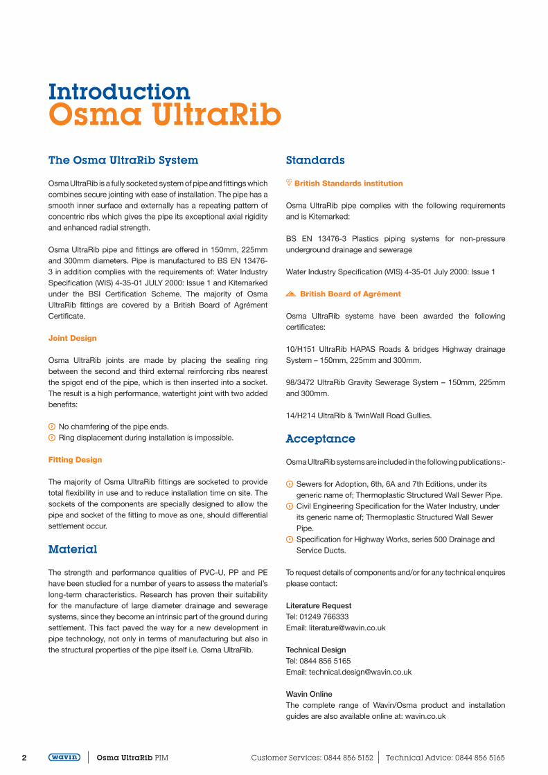
IntroductionOsma UltraRibThe Osma UltraRib System
Osma UltraRib is a fully socketed system of pipe and fittings which combines secure jointing with ease of installation. The pipe has a smooth inner surface and externally has a repeating pattern of concentric ribs which gives the pipe its exceptional axial rigidity and enhanced radial strength.
Osma UltraRib pipe and fittings are offered in 150mm, 225mm and 300mm diameters. Pipe is manufactured to BS EN 13476-3 in addition complies with the requirements of: Water Industry Specification (WIS) 4-35-01 JULY 2000: Issue 1 and Kitemarked under the BSI Certification Scheme. The majority of Osma UltraRib fittings are covered by a British Board of Agrément Certificate.
Joint Design
Osma UltraRib joints are made by placing the sealing ring between the second and third external reinforcing ribs nearest the spigot end of the pipe, which is then inserted into a socket.The result is a high performance, watertight joint with two added benefits:
No chamfering of the pipe ends. Ring displacement during installation is impossible.
Fitting Design
The majority of Osma UltraRib fittings are socketed to provide total flexibility in use and to reduce installation time on site. The sockets of the components are specially designed to allow the pipe and socket of the fitting to move as one, should differential settlement occur.
Material
The strength and performance qualities of PVC-U, PP and PE have been studied for a number of years to assess the material’s long-term characteristics. Research has proven their suitability for the manufacture of large diameter drainage and sewerage systems, since they become an intrinsic part of the ground during settlement. This fact paved the way for a new development in pipe technology, not only in terms of manufacturing but also in the structural properties of the pipe itself i.e. Osma UltraRib.
Standards
a British Standards institution
Osma UltraRib pipe complies with the following requirements and is Kitemarked:
BS EN 13476-3 Plastics piping systems for non-pressure underground drainage and sewerage
Water Industry Specification (WIS) 4-35-01 July 2000: Issue 1
$ British Board of Agrément
Osma UltraRib systems have been awarded the following certificates:
10/H151 UltraRib HAPAS Roads & bridges Highway drainage System – 150mm, 225mm and 300mm.
98/3472 UltraRib Gravity Sewerage System – 150mm, 225mm and 300mm.
14/H214 UltraRib & TwinWall Road Gullies.
Acceptance
Osma UltraRib systems are included in the following publications:-
Sewers for Adoption, 6th, 6A and 7th Editions, under its generic name of; Thermoplastic Structured Wall Sewer Pipe.
Civil Engineering Specification for the Water Industry, under its generic name of; Thermoplastic Structured Wall Sewer Pipe.
Specification for Highway Works, series 500 Drainage and Service Ducts.
To request details of components and/or for any technical enquires please contact:
Literature RequestTel: 01249 766333Email: [email protected]
Technical DesignTel: 0844 856 5165Email: [email protected]
Wavin OnlineThe complete range of Wavin/Osma product and installation guides are also available online at: wavin.co.uk

3www.wavin.co.uk Email: [email protected] Osma UltraRib PIM
Pipe and Joint TechnologyOsma UltraRib
External reinforcing ribs give exceptional axial rigidity and radial strength
Concentric external reinforcing ribs
Elastomeric Sealing Ring
Improved hydraulic flow due to the smooth interchange between pipe and fittings
The unique UltraRib high performance joint
4 Osma UltraRib PIM Customer Services: 0844 856 5152 Technical Advice: 0844 856 5165
General InformationOsma UltraRibApplication
Osma UltraRib systems are designed for use in gravity drainage and sewerage installations at depths of up to 10 metres. Adaptors and Reducers are available for connection to traditional materials.
Descriptions
Descriptions and illustrations in this publication are for guidance only. The fittings illustrated are generally typical of the Osma UltraRib 150mm sizes. No responsibility can be accepted for any errors, omissions or incorrect assumptions. Refer to the product itself if more detailed information is required. Due to the continuing programme of product improvement the Company reserves the right to amend any published information or to modify any product without prior notice.
Dimensions
Unless otherwise stated all dimensions are in millimetres (mm).
Symbols
a) British Standard Kitemark a Identifies pipes and fittings which are manufactured under
the B.S.I. Certification Scheme.
b) British Board of Agrément $ Identifies non-Kitemarked fittings which are covered by a
British Board of Agrément Certificate.
Materials
a) Pipes and Fittings All pipe is manufactured from unplastized Polyvinyl Chloride
(PVC-U). Fittings are either manufactured from Polypropylene (PP) or PVC-U. Polyethylene (PE) is used for the range of Road Gullies.
b) Sealing Rings Osma UltraRib Sealing rings are manufactured from Ethylene Propylene
Diene Monomer (EPDM) complying with the requirements of BS EN 681-1.
Colour
Most pipe and fittings – Golden BrownRing Seals – Black
Sealing rings
Sealing Rings are supplied loose with pipes and fittings and are included in the price.
Supply
The Osma UltraRib system is supplied through a nationwide network of merchant distributors. For further information contact Customer Services on 0844 856 5152.
Literature
The following Wavin publications are also available from the Literature Department at Chippenham.
General Wavin Below Ground & Civils System: Trade Price List
Gravity Drain and Sewer Systems OsmaDrain System: Product and Installation Manual
Osma Non Man-Entry Inspection Chamber Range: Product and Installation Manual
Stormwater Management Systems Wavin AquaCell System: Product and Installation Manual
Wavin Flow Control Range: Product and Installation Manual
Wavin Commercial Rainwater Re-use System: Product Overview
Wavin Poly-Concrete Channel Systems: Product and Installation Manual
Wavin Quickstream Siphonic Roof Drainage Systems: Product and Installation Manual

5www.wavin.co.uk Email: [email protected] Osma UltraRib PIM
Weights and DimensionsOsma UltraRibThe following pages illustrate the 150mm, 225mm and 300mm Osma UltraRib range of underground gravity drainage and sewerage pipes, fittings and accessories. Part numbers, descriptions, dimensions and weights of pipe are included.
The Osma UltraRib range of pipes comply with the requirements of BS EN 13476-3 and are Kitemarked in accordance with the BSI certification scheme. Osma UltraRib pipe is supplied in three diameters, 150mm, 225mm and 300mm, either plain ended or single socketed and in standard lengths of either 3 or 6 metres.
Table 1: Pipe weights
Plain Ended (P/E)
NominalSize (mm)
Length(m)
Weight(kg/m)
PartNumber
150 3 2.3 6UR073225 3 4.9 9UR073300 3 7.2 12UR073
Single Socket (S/S)
NominalSize (mm)
Length(m)
Weight(kg/m)
PartNumber
150 3 2.4 6UR0436 2.3 6UR046
225 3 5.2 9UR0436 5.0 9UR046
300 3 7.8 12UR043
Table 2: Pipe and socket dimensions
Plain Ended Pipe (P/E)
NominalSize (mm) OD ID
150 170 152225 250 226300 335 300
Single Socketed Pipe (S/S)
NominalSize (mm) OD A
150 190 96225 275 118300 372 136
Osma UltraRib Socket
NominalSize (mm) OD A
150 183 86225 266 123300 356 141
OD ID
A
OD
A
OD
6 Osma UltraRib PIM Customer Services: 0844 856 5152 Technical Advice: 0844 856 5165
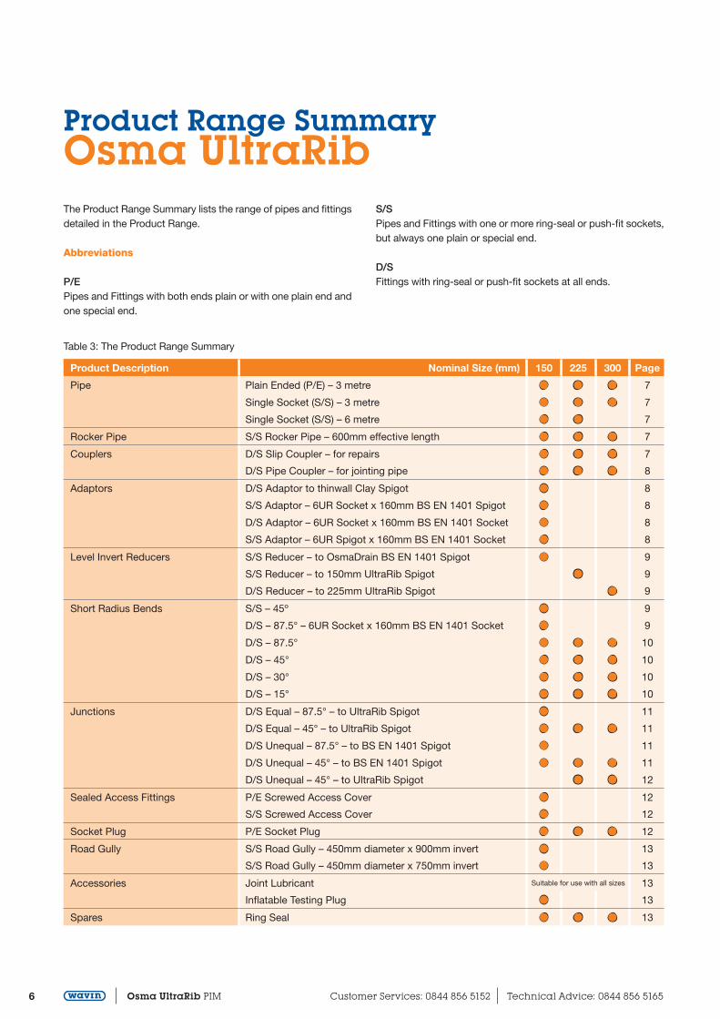
Product Range SummaryOsma UltraRibThe Product Range Summary lists the range of pipes and fittings detailed in the Product Range.
Abbreviations
P/EPipes and Fittings with both ends plain or with one plain end and one special end.
S/SPipes and Fittings with one or more ring-seal or push-fit sockets,but always one plain or special end.
D/SFittings with ring-seal or push-fit sockets at all ends.
Table 3: The Product Range Summary
Product Description Nominal Size (mm) 150 225 300 Page
Pipe Plain Ended (P/E) – 3 metre l l l 7
Single Socket (S/S) – 3 metre l l l 7
Single Socket (S/S) – 6 metre l l 7
Rocker Pipe S/S Rocker Pipe – 600mm effective length l l l 7
Couplers D/S Slip Coupler – for repairs l l l 7
D/S Pipe Coupler – for jointing pipe l l l 8
Adaptors D/S Adaptor to thinwall Clay Spigot l 8
S/S Adaptor – 6UR Socket x 160mm BS EN 1401 Spigot l 8
D/S Adaptor – 6UR Socket x 160mm BS EN 1401 Socket l 8
S/S Adaptor – 6UR Spigot x 160mm BS EN 1401 Socket l 8
Level Invert Reducers S/S Reducer – to OsmaDrain BS EN 1401 Spigot l 9
S/S Reducer – to 150mm UltraRib Spigot l 9
D/S Reducer – to 225mm UltraRib Spigot l 9
Short Radius Bends S/S – 45º l 9
D/S – 87.5° – 6UR Socket x 160mm BS EN 1401 Socket l 9
D/S – 87.5° l l l 10
D/S – 45° l l l 10
D/S – 30° l l l 10
D/S – 15° l l l 10
Junctions D/S Equal – 87.5° – to UltraRib Spigot l 11
D/S Equal – 45° – to UltraRib Spigot l l l 11
D/S Unequal – 87.5° – to BS EN 1401 Spigot l 11
D/S Unequal – 45° – to BS EN 1401 Spigot l l l 11
D/S Unequal – 45° – to UltraRib Spigot l l 12
Sealed Access Fittings P/E Screwed Access Cover l 12
S/S Screwed Access Cover l 12
Socket Plug P/E Socket Plug l l l 12
Road Gully S/S Road Gully – 450mm diameter x 900mm invert l 13
S/S Road Gully – 450mm diameter x 750mm invert l 13
Accessories Joint Lubricant Suitable for use with all sizes 13
Inflatable Testing Plug l 13
Spares Ring Seal l l l 13

7 www.wavin.co.uk Email: [email protected] Osma UltraRib PIM
Product DetailsOsma UltraRibPipe
Plain Ended Pipe
Material: PVC-U
Nominal Part LengthSize (mm) Number (m)
150 6UR073 a $ WIS 3225 9UR073 a $ WIS 3300 12UR073 a $ WIS 3
Single Socketed Pipe
Material: PVC-U
Nominal Part LengthSize (mm) Number (m)
150 6UR043 a $ WIS 3225 9UR043 a $ WIS 3300 12UR043 a $ WIS 3225 6UR046 a $ WIS 6300 9UR046 a $ WIS 6
Rocker Pipe
A
B
Single Socketed Rocker Pipe
Material: PVC-U
Nominal Part Dimensions (mm)Size (mm) Number A B
150 6UR869 a $ 600* 190225 9UR869 a $ 600* 275300 12UR869 a $ 600* 372
*Dimension A = effective length
Couplers
A D/S Slip Coupler
• For new branch entry connections and repairs
Material: PVC-U* / Polypropylene†
Nominal Part Dimensions (mm)Size (mm) Number A
150* 6UR105 a $ 185225† 9UR105 a $ 240300† 12UR105 a $ 325

8 Osma UltraRib PIM Customer Services: 0844 856 5152 Technical Advice: 0844 856 5165
Product DetailsOsma UltraRib
AB
D/S Pipe Coupler
• For jointing pipe
Material: PVC-U* / Polypropylene†
Nominal Part Dimensions (mm)Size (mm) Number A B
150* 6UR205 a $ WIS 185 12225† 9UR205 a $ WIS 241 12300† 12UR205 a $ WIS 301 15
Adaptors
A
B
D/S Adaptor
• Connector to BS EN 295 thinwall clay spigot
Material: PVC-U
Nominal Part Dimensions (mm)Size (mm) Number A B
150 6UR129 $ 193 180
A
B
C
S/S Adaptor
• 6UR socket x 160mm BS EN 1401 spigot
Material: PVC-U
Nominal Part Dimensions (mm)Size (mm) Number A B C
150 6UR141 $ 180 84 160
B
A
C
D/S Adaptor
• 6UR socket x 160mm BS EN 1401 socket
Material: PVC-U
Nominal Part Dimensions (mm)Size (mm) Number A B C
150 6UR142 $ 170 76 161
A
B
C
S/S Adaptor
• 6UR socket x 160mm BS EN 1401 socket
Material: PVC-U
Nominal Part Dimensions (mm)Size (mm) Number A B C
150 6UR143 $ 121 42 161

9 www.wavin.co.uk Email: [email protected] Osma UltraRib PIM
Reducers
B
A
CS/S Level Invert Reducer
• To 110mm OsmaDrain spigot
Material: PVC-U
Nominal Part Dimensions (mm)Size (mm) Number A B C
150x110 6UR099 $ 115 95 111
B
A
C
S/S Level Invert Reducer
• To 150mm UltraRib spigot
Material: Polypropylene
Nominal Part Dimensions (mm)Size (mm) Number A B C
225x150 9UR095 $ 142 122 170
D/S Level Invert Reducer
• To 225mm UltraRib spigot
Material: Polypropylene
Nominal Part Dimensions (mm)Size (mm) Number A B C
300x225 12UR093 $ 165 155 250
Short Radius Bends
A
B
S/S Short Radius Bend – 45°
Material: PVC-U
Nominal Part Dimensions (mm)Size (mm) Number A B
150 6UR163 $ 138 65
A
B
D/S Short Radius Bend – 87.5°
• 6UR socket x 160mm BS EN 1401 socket
Material: PVC-U
Nominal Part Dimensions (mm)Size (mm) Number A B
150 6UR560 $ 265 255

10 Osma UltraRib PIM Customer Services: 0844 856 5152 Technical Advice: 0844 856 5165
Product DetailsOsma UltraRib
A
B
D/S Short Radius Bend – 87.5° u
• 225/300mm bend are long radius
Material: PVC-U* / Polypropylene†
Nominal Part Dimensions (mm)Size (mm) Number A B
150* 6UR561 $ 265 265225† 9UR561 $ 604 604300† 12UR561 $ 757 757
AB
D/S Short Radius Bend – 45° u
Material: PVC-U* / Polypropylene†
Nominal Part Dimensions (mm)Size (mm) Number A B
150* 6UR563 $ 138 138225† 9UR563 $ 200 200300† 12UR563 $ 225 225
AB
D/S Short Radius Bend – 30° u
Material: PVC-U* / Polypropylene†
Nominal Part Dimensions (mm)Size (mm) Number A B
150* 6UR566 $ 125 125225† 9UR566 $ 205 205300† 12UR566 $ 230 230
AB
D/S Short Radius Bend – 15° u
Material: PVC-U* / Polypropylene†
Nominal Part Dimensions (mm)Size (mm) Number A B
150* 6UR567 $ 114 114225† 9UR567 $ 165 165300† 12UR567 $ 180 180
u Actual product for the 9UR and 12UR sizes may differ from image shown.
11 www.wavin.co.uk Email: [email protected] Osma UltraRib PIM
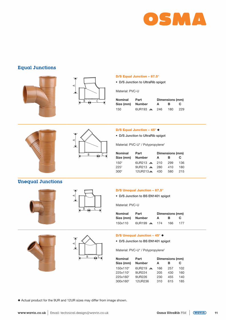
Equal Junctions
B C
AD/S Equal Junction – 87.5°
• D/S Junction to UltraRib spigot
Material: PVC-U
Nominal Part Dimensions (mm)Size (mm) Number A B C
150 6UR193 $ 246 180 229
B C
A
D/S Equal Junction – 45° u
• D/S Junction to UltraRib spigot
Material: PVC-U* / Polypropylene†
Nominal Part Dimensions (mm)Size (mm) Number A B C
150* 6UR213 $ 210 299 136225† 9UR213 $ 280 410 180300† 12UR213 $ 430 580 215
Unequal Junctions
B C
A
D/S Unequal Junction – 87.5°
• D/S Junction to BS EN1401 spigot
Material: PVC-U
Nominal Part Dimensions (mm)Size (mm) Number A B C
150x110 6UR199 $ 174 166 177
B C
A
D/S Unequal Junction – 45° u
• D/S Junction to BS EN1401 spigot
Material: PVC-U* / Polypropylene†
Nominal Part Dimensions (mm)Size (mm) Number A B C
150x110* 6UR219 $ 166 257 102225x110† 9UR224 205 430 160225x160† 9UR226 230 455 140300x160† 12UR236 310 615 185
u Actual product for the 9UR and 12UR sizes may differ from image shown.

12 Osma UltraRib PIM Customer Services: 0844 856 5152 Technical Advice: 0844 856 5165
Product DetailsOsma UltraRib
B C
A
D/S Unequal Junction – 45° u
• D/S Junction to UltraRib spigot
Material: PVC-U* / Polypropylene†
Nominal Part Dimensions (mm)Size (mm) Number A B C
225x150† 9UR227 $ 298 455 140300x150† 12UR237 $ 327 615 185300x225† 12UR240 $ 430 580 215
Sealed Access Fittings
A
B
C
P/E Screwed Access Cover
• Allows full bore access to the sewerage system for cleaning, fits in to a standard UltraRib socket
Material: PVC-U
Nominal Part Dimensions (mm)Size (mm) Number A B C
150 6UR292 $ 41 87 196
A
B
C
S/S Screwed Access Cover
• Allows full bore access to the sewerage system for cleaning, fits on to a standard UltraRib spigot
Material: PVC-U
Nominal Part Dimensions (mm)Size (mm) Number A B C
150 6UR290 $ 41 153 196
Socket Plug
A
B
P/E Socket Plug
• Allows full bore access to the sewerage system for cleaning, fits in to a standard UltraRib socket
Material: PVC-U* / Polypropylene†
Nominal Part Dimensions (mm)Size (mm) Number A B
150* 6UR296 $ 92 195225† 9UR296 $ 110 250300† 12UR296 $ 155 335
u Actual product for the 9UR and 12UR sizes may differ from image shown.

13 www.wavin.co.uk Email: [email protected] Osma UltraRib PIM
Road Gully
B
C
D
A
S/S Trapped Road Gully
• 6UR600 = 450mm diameter x 900mm deep• 6UR590 = 450mm diameter x 750mm deep
Material: Polyethylene
Nominal Part Dimensions (mm)Size (mm) Number A B C D
150 6UR600 $ 900 465 444 720150 6UR590 $ 760 402 368 580
Lubricant
Jointing Lubricant
• Soluble Lubricant
Nominal PartSize (kg) Number
2.5kg tub 6UR3955.0kg tub 6UR396
Spares – General
Ring Seal
• Spare, standard UltraRib socket
Material: EPDM
Nominal PartSize (mm) Number
150 6UR117225 9UR117300 12UR117
14 Osma UltraRib PIM Customer Services: 0844 856 5152 Technical Advice: 0844 856 5165
Transport, Handling and StorageOsma UltraRibResources and Planning
The main contractor, or sub-contractor, needs no special equipment or power.
Contractors are responsible for checking layout drawings to ensure they are correct so that expensive site alterations do not have to be made after laying.
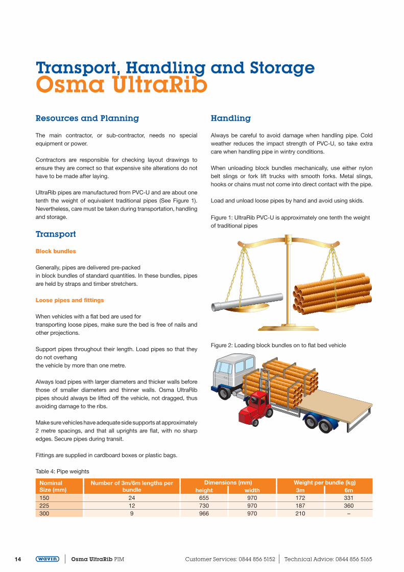
UltraRib pipes are manufactured from PVC-U and are about one tenth the weight of equivalent traditional pipes (See Figure 1). Nevertheless, care must be taken during transportation, handling and storage.
Transport
Block bundles
Generally, pipes are delivered pre-packedin block bundles of standard quantities. In these bundles, pipes are held by straps and timber stretchers.
Loose pipes and fittings
When vehicles with a flat bed are used fortransporting loose pipes, make sure the bed is free of nails and other projections.
Support pipes throughout their length. Load pipes so that they do not overhangthe vehicle by more than one metre.
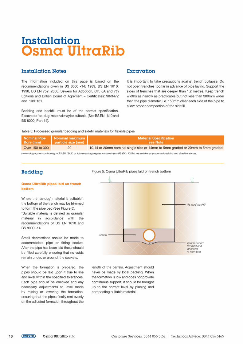
Always load pipes with larger diameters and thicker walls before those of smaller diameters and thinner walls. Osma UltraRib pipes should always be lifted off the vehicle, not dragged, thus avoiding damage to the ribs.
Make sure vehicles have adequate side supports at approximately 2 metre spacings, and that all uprights are flat, with no sharp edges. Secure pipes during transit.
Fittings are supplied in cardboard boxes or plastic bags.
Handling
Always be careful to avoid damage when handling pipe. Cold weather reduces the impact strength of PVC-U, so take extra care when handling pipe in wintry conditions.
When unloading block bundles mechanically, use either nylon belt slings or fork lift trucks with smooth forks. Metal slings, hooks or chains must not come into direct contact with the pipe.
Load and unload loose pipes by hand and avoid using skids.
Figure 1: UltraRib PVC-U is approximately one tenth the weight of traditional pipes
Figure 2: Loading block bundles on to flat bed vehicle
Table 4: Pipe weights
NominalSize (mm)
Number of 3m/6m lengths per bundle
Dimensions (mm) Weight per bundle (kg)height width 3m 6m
150 24 655 970 172 331225 12 730 970 187 360300 9 966 970 210 –

15www.wavin.co.uk Email: [email protected] Osma UltraRib PIM
Storage
Block Bundles
Store block bundles on a reasonably flat surface free from sharp projections likely to damage the pipes.
Block bundles can be stored up to three high without extra side supports or bearers. In addition, block bundles will remain free standing when cut.
Take care when removing pipes from bundles as the straps are under considerable tension and may flail when cut.
Loose pipes
Store loose pipes on a reasonably flat surface free of sharp projections. Provide side supports at least every 2 metres. These supports should preferably consist of battens at least 75mm wide (See Figure 3).
Ideally, loose pipes should be uniformly supported throughout their entire length. If this is not possible, place timber supports at least 75mm wide at 1 metre maximum centres beneath the pipes (See Figure 4).
Stack pipes of different size and wall thickness separately. If this is not possible, stack pipes with larger diameters and thicker walls under those with smaller diameters and thinner walls.
Socketed pipes should be stacked with the sockets protruding and placed at alternate ends. Do not stack pipes more than seven layers in height or above a maximum height of 2 metres.
Fittings
Store fittings supplied in plastic bags away from direct sunlight.
If fittings have to be stored outside in their plastic bags, open the bags to prevent a build-up of temperature.
The above storage requirements apply to the United Kingdom climatic conditions. In tropical climates reduce the stack height and store pipes and fittings under cover or in the shade.
Sealing rings
Sealing Rings for the majority of UltraRib fittings are supplied loose. The rings should be stored in their original packaging away from strong sunlight or weathering. They should never be placed on the ends of the pipes which are being stored.
Figure 3: Storage of loose pipes on the ground
2m
2m o
r 7
laye
rs m
ax.
Figure 4: Storage of loose pipes on bearers
1m spacing maximum
75mm bearing width
16 Osma UltraRib PIM Customer Services: 0844 856 5152 Technical Advice: 0844 856 5165
InstallationOsma UltraRibInstallation Notes
The information included on this page is based on the recommendations given in BS 8000 -14: 1989, BS EN 1610: 1998, BS EN 752: 2008, Sewers for Adoption, 6th, 6A and 7th Editions and British Board of Agrément – Certificates: 98/3472 and 10/H151.
Bedding and backfill must be of the correct specification. Excavated ‘as-dug’ material may be suitable. (See BS EN 1610 and BS 8000: Part 14).
Excavation
It is important to take precautions against trench collapse. Do not open trenches too far in advance of pipe laying. Support the sides of trenches that are deeper than 1.2 metres. Keep trench widths as narrow as practicable but not less than 300mm wider than the pipe diameter, i.e. 150mm clear each side of the pipe to allow proper compaction of the sidefill.
Bedding
Osma UltraRib pipes laid on trench bottom
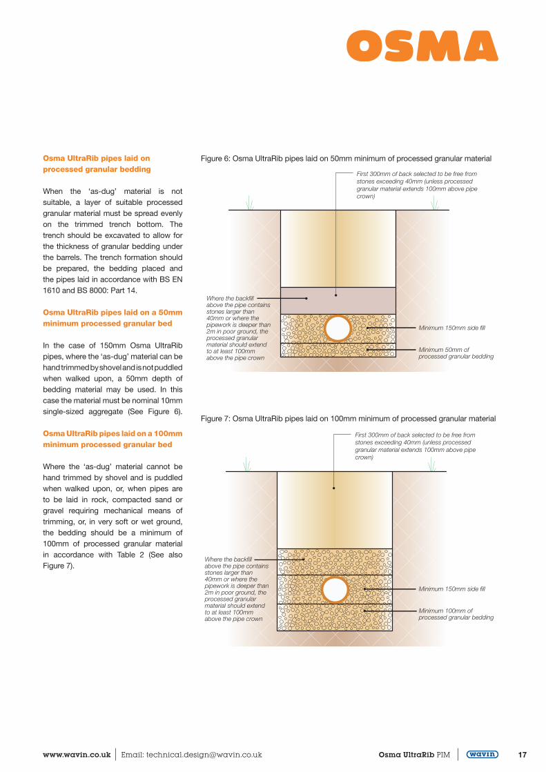
Where the ‘as-dug’ material is suitable*, the bottom of the trench may be trimmed to form the pipe bed (See Figure 5).*Suitable material is defined as granular material in accordance with the recommendations of BS EN 1610 and BS 8000 -14.
Small depressions should be made to accommodate pipe or fitting socket. After the pipe has been laid these should be filled carefully ensuring that no voids remain under, or around, the sockets.
When the formation is prepared, the pipes should be laid upon it true to line and level within the specified tolerances. Each pipe should be checked and any necessary adjustments to level made by raising or lowering the formation, ensuring that the pipes finally rest evenly on the adjusted formation throughout the
29
‘As-dug’ backfill
Trench bottom trimmed and loosened to form bed
Sidefill
Figure 5: Osma UltraRib pipes laid on trench bottom
length of the barrels. Adjustment should never be made by local packing. When the formation is low and does not provide continuous support, it should be brought up to the correct level by placing and compacting suitable material.
Table 5: Processed granular bedding and sidefill materials for flexible pipes
Nominal Pipe Bore (mm)
Nominal maximum particle size (mm)
Material Specification see Note
Over 150 to 300 20 10,14 or 20mm nominal single size or 14mm to 5mm graded or 20mm to 5mm graded
Note – Aggregates conforming to BS EN 12620 or lightweight aggregates conforming to BS EN 13055-1 are suitable as processed bedding and sidefill materials.
17www.wavin.co.uk Email: [email protected] Osma UltraRib PIM
Osma UltraRib pipes laid on processed granular bedding When the ‘as-dug’ material is not suitable, a layer of suitable processed granular material must be spread evenly on the trimmed trench bottom. The trench should be excavated to allow for the thickness of granular bedding under the barrels. The trench formation should be prepared, the bedding placed and the pipes laid in accordance with BS EN 1610 and BS 8000: Part 14.
Osma UltraRib pipes laid on a 50mm minimum processed granular bed In the case of 150mm Osma UltraRib pipes, where the ‘as-dug’ material can be hand trimmed by shovel and is not puddled when walked upon, a 50mm depth of bedding material may be used. In this case the material must be nominal 10mm single-sized aggregate (See Figure 6).
Osma UltraRib pipes laid on a 100mm minimum processed granular bed Where the ‘as-dug’ material cannot be hand trimmed by shovel and is puddled when walked upon, or, when pipes are to be laid in rock, compacted sand or gravel requiring mechanical means of trimming, or, in very soft or wet ground, the bedding should be a minimum of 100mm of processed granular material in accordance with Table 2 (See alsoFigure 7).
Figure 6: Osma UltraRib pipes laid on 50mm minimum of processed granular material
Figure 7: Osma UltraRib pipes laid on 100mm minimum of processed granular material
29
Minimum 150mm side fill
Minimum 50mm ofprocessed granular bedding
Where the backfillabove the pipe containsstones larger than40mm or where thepipework is deeper than2m in poor ground, theprocessed granularmaterial should extendto at least 100mmabove the pipe crown
First 300mm of back selected to be free fromstones exceeding 40mm (unless processedgranular material extends 100mm above pipecrown)
29
First 300mm of back selected to be free fromstones exceeding 40mm (unless processedgranular material extends 100mm above pipecrown)
Minimum 150mm side fill
Minimum 100mm ofprocessed granular bedding
Where the backfillabove the pipe containsstones larger than40mm or where thepipework is deeper than2m in poor ground, theprocessed granularmaterial should extendto at least 100mmabove the pipe crown
18 Osma UltraRib PIM Customer Services: 0844 856 5152 Technical Advice: 0844 856 5165
InstallationOsma UltraRibBackfill Sequence
1. Place suitable sidefill material evenly on each side of the pipe in 100mm layers. Pay particular attention to the area under the lower quadrants of the pipe. Hand tamp well at each layer up to the pipe crown. Leave the pipe crown exposed.
2. If ‘as-dug’ material is free from stones exceeding 40mm, imported processed granular material is not needed above the pipe crown (See Figure 6). Cover the pipe crown with a minimum of 300mm of compacted ‘as-dug’ material. If ‘as-dug’ material contains stones larger than 40mm, or the pipe is deeper than 2 metres in poor ground, extend the processed granular material for at least 100mm above the pipe crown.
3. In both cases, hand tamp the material fully at the sides of the pipe while tamping lightly over the crown. Continue hand tamping until a finished layer of 300mm, 225mm in adoptable situations, has been placed over the pipe.
4. ‘As-dug’ material may be backfilled in 300mm/225mm layers and mechanically tamped. Dumpers or other vehicles must not be driven along the pipe tracks as a means of compacting. Surround vertical or steeply raking pipes with 150mm bedding material, suitably tamped up to the invert level of the incoming pipe (Backdrops) or to ground level. Then backfill as above.
Pipe Protection
As PVC-U pipes are flexible they can accommodate a degree of ground movement and pressure without damage. However, if the pipe needs protection the following recommendations should be followed:-
Traffic free areas
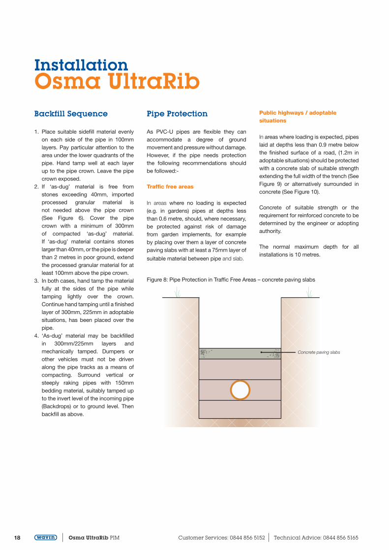
In areas where no loading is expected (e.g. in gardens) pipes at depths less than 0.6 metre, should, where necessary, be protected against risk of damage from garden implements, for example by placing over them a layer of concrete paving slabs with at least a 75mm layer of
suitable material between pipe and slab.
Public highways / adoptable situations
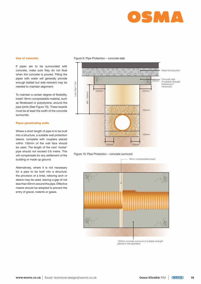
In areas where loading is expected, pipes laid at depths less than 0.9 metre below the finished surface of a road, (1.2m in adoptable situations) should be protected with a concrete slab of suitable strength extending the full width of the trench (See Figure 9) or alternatively surrounded in concrete (See Figure 10).
Concrete of suitable strength or the requirement for reinforced concrete to be determined by the engineer or adopting authority.
The normal maximum depth for all installations is 10 metres.
Figure 8: Pipe Protection in Traffic Free Areas – concrete paving slabs
Concrete paving slabs
19www.wavin.co.uk Email: [email protected] Osma UltraRib PIM
Use of concrete If pipes are to be surrounded with concrete, make sure they do not float when the concrete is poured. Filling the pipes with water will generally provide enough ballast but side restraint may be needed to maintain alignment.
To maintain a certain degree of flexibility, insert 18mm compressible material, such as fibreboard or polystyrene, around the pipe joints (See Figure 10). These boards must be at least the width of the concrete surrounds.
Pipes penetrating walls
Where a short length of pipe is to be built into a structure, a suitable wall protection sleeve, complete with couplers placed within 150mm of the wall face should be used. The length of the next ‘rocker’ pipe should not exceed 0.6 metre. This will compensate for any settlement of the building or made up ground.
Alternatively, where it is not necessary for a pipe to be built into a structure, the provision of a lintel, relieving arch or sleeve may be used, leaving a gap of not less than 50mm around the pipe. Effective means should be adopted to prevent the entry of gravel, rodents or gases.
Figure 9: Pipe Protection – concrete slab
Figure 10: Pipe Protection – concrete surround
Concrete slabof suitable strength(reinforced ifnecessary)
Road Construction
200mm200mm
150mm
100mm
150mm
150mm150mm
Less
than
1.2
m
Min
. 150
mm
18mm compressible board
150mm concrete surround of suitable strengthplaced in one operation

20 Osma UltraRib PIM Customer Services: 0844 856 5152 Technical Advice: 0844 856 5165
InstallationOsma UltraRibJointing
Unlike traditional methods for jointing PVC-U systems, the UltraRib method is unique and innovative, since the ring seal is positioned over the pipe spigot rather than being retained within a pipe or fitting socket (See Figure 12).
The major advantages of the UltraRib jointing method are:
There is no need to chamfer pipe ends The ring seal cannot be displaced during jointing
The design of the joint ensures a flush fit between the internal bore of the pipe and the fitting thus increasing its hydraulic performance
Preparation
Ensure that the two ribs that retain the sealing ring are sound.
Cutting
Pipe must be cut midway between the ribs. The design of the ribs allows the pipe to be cut square using a coarse toothed saw (See Figure 11).
Jointing sequence
1. Clean pipe spigots and sockets. All dust, dirt and grit which could prevent an effective seal must be removed from pipe ends and sockets.
2. The correct position for the sealing ring is indicated in Figure 12, ie between the second and third ribs from the pipe end. Ensure the ring seal is correctly seated and not twisted.
3. Lubricant should be applied to the whole of the inside of the socket (See Figure 13).
4. To make the joint, offer up the pipe to the socket, align pipe and push home. Alignment is important to facilitate jointing.
The force required to push the pipe home will vary according to pipe size and ambient temperature. Whatever method is used to apply the neccessary force, care must be taken to ensure that there is no risk of damaging the pipe ends. The most convenient method is to use a lever ensuring the pipe end is protected (See Figure 14).
A good technique is to lift the pipe up by passing a rope underneath (See Figure 15). This makes it easier to align the spigot into the socket. Mechanical pulling or pushing methods are unnecessary.
Figure 16: Section through pipe joint
Figure 11: Correct cutting position Figure 12: UltraRib Sealing Ring
Figure 14: Protecting the pipe end
Figure 15: Aligning spigot into socket
Figure 13: Applying the lubricant
21www.wavin.co.uk Email: [email protected] Osma UltraRib PIM
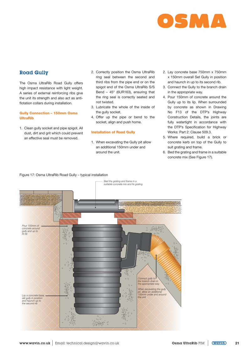
Road Gully
The Osma UltraRib Road Gully offers high impact resistance with light weight. A series of external reinforcing ribs give the unit its strength and also act as anti-flotation collars during installation.
Gully Connection – 150mm Osma UltraRib
1. Clean gully socket and pipe spigot. All dust, dirt and grit which could prevent an effective seal must be removed.
2. Correctly position the Osma UltraRib ring seal between the second and third ribs from the pipe end or on the spigot end of the Osma UltraRib S/S Bend – 45° (6UR163), ensuring that the ring seal is correctly seated and not twisted.
3. Lubricate the whole of the inside of the gully socket.
4. Offer up the pipe or bend to the socket, align and push home.
Installation of Road Gully
1. When excavating the Gully pit allow an additional 150mm under and around the unit.
2. Lay concrete base 750mm x 750mm x 150mm overall Set Gully in position and haunch in up to its second rib.
3. Connect the Gully to the branch drain in the appropriate way.
4. Pour 150mm of concrete around the Gully up to its lip. When surrounded by concrete as shown in Drawing No F13 of the DTP’s Highway Construction Details, the joints are fully watertight in accordance with the DTP’s Specification for Highway Works: Part 2: Clause 509.3.
5. Where required, build a brick or concrete kerb on top of the Gully to suit grating and frame.
6. Bed the grating and frame in a suitable concrete mix (See Figure 17).
Lay a concrete base,set gully in positionand haunch up tothe second rib
Pour 150mm ofconcrete aroundgully and up toits lip
Bed the grating and frame in asuitable concrete mix and fix grating
Connect gully tothe branch drain inthe appropriate way
When excavating the gullypit, allow an additional150mm under and aroundthe unit
Figure 17: Osma UltraRib Road Gully – typical installation
22 Osma UltraRib PIM Customer Services: 0844 856 5152 Technical Advice: 0844 856 5165
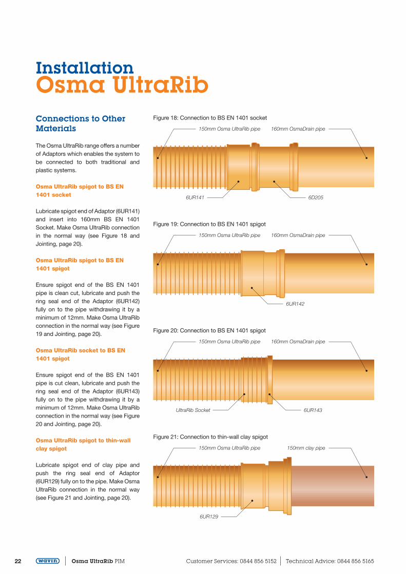
InstallationOsma UltraRibConnections to Other Materials
The Osma UltraRib range offers a number of Adaptors which enables the system to be connected to both traditional and plastic systems.
Osma UltraRib spigot to BS EN 1401 socket
Lubricate spigot end of Adaptor (6UR141) and insert into 160mm BS EN 1401 Socket. Make Osma UltraRib connection in the normal way (see Figure 18 and Jointing, page 20).
Osma UltraRib spigot to BS EN 1401 spigot
Ensure spigot end of the BS EN 1401 pipe is clean cut, lubricate and push the ring seal end of the Adaptor (6UR142) fully on to the pipe withdrawing it by a minimum of 12mm. Make Osma UltraRib connection in the normal way (see Figure 19 and Jointing, page 20).
Osma UltraRib socket to BS EN 1401 spigot
Ensure spigot end of the BS EN 1401 pipe is cut clean, lubricate and push the ring seal end of the Adaptor (6UR143) fully on to the pipe withdrawing it by a minimum of 12mm. Make Osma UltraRib connection in the normal way (see Figure 20 and Jointing, page 20).
Osma UltraRib spigot to thin-wall clay spigot
Lubricate spigot end of clay pipe and push the ring seal end of Adaptor (6UR129) fully on to the pipe. Make Osma UltraRib connection in the normal way (see Figure 21 and Jointing, page 20).
Figure 18: Connection to BS EN 1401 socket
150mm Osma UltraRib pipe 160mm OsmaDrain pipe
6D2056UR141
Figure 19: Connection to BS EN 1401 spigot
150mm Osma UltraRib pipe 160mm OsmaDrain pipe
6UR142
Figure 20: Connection to BS EN 1401 spigot
150mm Osma UltraRib pipe 160mm OsmaDrain pipe
6UR143UltraRib Socket
Figure 21: Connection to thin-wall clay spigot
150mm Osma UltraRib pipe 150mm clay pipe
6UR129

23www.wavin.co.uk Email: [email protected] Osma UltraRib PIM
Testing, Safety and MaintenaceOsma UltraRibTesting
All lengths of the drain and all manholes and inspection chambers must be inspected for straightness, obstructions and for ground water infiltration.
They must also pass the following tests which must be carried out in the presence of an Authority’s Inspector.
Water test
Authorities require this test to be carried out in suitable lengths as work proceeds as well as after backfilling is completed.
Gravity drains should be tested to an internal pressure of:
1.5 metres head of water above the invert of the pipe at the high end of the line and not more than 4 metres head of water above the invert of the pipe at the lower end of the line.
Fill the pipe and allow two hours for settlement, topping up as necessary. Then add water for 30 minutes to maintain the test head. Note the quantity of water needed. Water loss may be due to trapped air or leakage. The rate of water loss should not exceed 1 l/h per metre diameter per linear metre run of pipe (see BS 8000: Part 14: 1989 Clause 5.1.4.3).
Air test
It may be quicker and more convenient to carry out an air test, especially for large pipes or when water is not available. However because this test is more sensitive than a water test and is affected by any changes in temperature, failure is not conclusive. And since it is difficult to detect the point of failure with an air test a water test should be carried out if failure does occur.
Pump air into the system until a pressure of:
100mm head of water is shown on a connected U-tube for standard pipe lines, or:
50mm head of water is shown on a connected U-tube where gullied and/or ground floor appliances are connected. The 100mm head of water pressure should not fall by more than 25mm over a period of five minutes.
The 50mm head of water pressure should not fall by more than 12.5mm over a period of five minutes.
Smoke test
Smoke tests are not officially accepted tests but are used to detect leakage points after other tests have failed.
Certain smoke canisters are not suitable for use with PVC-U drainage systems. Obtain the advice of the canister manufacturers before testing by this method.
Safety
The relevant regulations detailed in the Health and Safety at Work Act 1974 must be adhered to on site.
Solvent Cements, Fillers and Degreasing Cleaners
When making solvent weld joints, it is essential to observe normal safety rules for handling solvents.
Never smoke or bring naked flames near the area of work. Work in a well ventilated area to avoid inhaling fumes. Close the solvent container after use and store in a cool place.
Do not allow solvents or cleaners to come into contact with the skin.
Handling and Trench Safety Take care when removing pipes from bundles as the straps are under considerable tension and may flail when cut.
Follow the relevant British Standard Codes of Practice and Sewers for Adoption when digging trenches to prevent accidents from trench collapse.
Use the correct fencing and marking whenever a trench is accessible to the public.
Maintenance
The smooth bore of Osma UltraRib pipes combined with their long lengths reduce the risk of blockages. However if a blockage does occur, use only flexible or roller type rods. Pointed or boring type metal fittings are NOT recommended. Tests have been carried out on PVC-U pipes and fittings from specialist drain cleaning contractors and their normal equipment is suitable. Do not use specialist cutting attachments.
Water jetting
For guidance on good working practice when using water jetting equipment for the unblocking and cleaning of all types of drains and sewers refer to the WRc Sewer Jetting Code of Practice. 2nd Edition, Sections 5.4.2., 5.4.3. and 5.4.4.
Copies are available from: Publications, WRc plc, Frankland Road, Blagrove, Swindon, SN5 8YF
Tel: 01793 511711
Email: [email protected]

24 Osma UltraRib PIM Customer Services: 0844 856 5152 Technical Advice: 0844 856 5165
NotesOsma UltraRib

© 2017 Wavin Limited
Wavin operates a programme of continuous product development, and therefore reserves the right to modify or amend the specification of their products without notice. All information in this publication is given in good faith, and believed to be correct at the time of going to press. However, no responsibility can be accepted for any errors, omissions or incorrect assumptions. Users should satisfy themselves that products are suitable for the purpose and application intended.
For further product information visit: wavin.co.uk
Wavin LimitedRegistered OfficeEdlington Lane Doncaster | DN12 1BYTel. 0844 856 5152www.wavin.co.uk | [email protected]
UR
102
– A
ugus
t 20
17
Discover our broad portfolio atwww.wavin.co.uk
Water management | Plumbing and heating | Waste water drainageWater and gas distribution | Cable ducting