process control design - intuition or analysis
TRANSCRIPT


Chapter 10
Control Design: Intuition or Analysis?
Dan P. Dumdie
10.1 Introduction
In previous chapters, we discussed some of the many different types of control methods availableand typically used in the pulp and paper industry (simple feedback, cascade, ratio, feedforward, etc.)It is not uncommon, in practice, to use anyone of these control methods for a given application.
The blending and mixing oftwo process streams is a typical application important to all industries.In pulp and paper, it is common to blend dilution water with a pulp slurry to do consistency control.This is a process. that can be modeled by a material balance.
We can also blend a hot process stream with a cold process stream to do temperature control. Thisis a process that can be modeled by both a material and an energy balance.
Although these two processes have different controlled variables, they are both analogous toblending and, therefore, are very similar from a process control standpoint. Furthermore, it ispossible to control consistency or temperature using anyone of the feedback, cascade, ratio, orfeedforward algorithms. This raises several questions. Which control method is best? How do weevaluate each method? Which method is the most cost effective? How do we determine whichmethod to use for a specific application?
This chapter answers all of these questions by looking at two very different approaches to controlsystem design and analysis. First, we will design by intuition, an approach used by many engineersthat draws from their experience and training. Next, we will design by analysis. This is a systemsapproach using material and energy balance equations to determine the best control strategy. Finally,a comparison of these two design methods will be done by outlining the advantages anddisadvantages of each for several specific applications.
The reader should understand that there are many other analogous blending and mixing processesin the pulp and paper industry to which the control theory in this chapter applies. In addition, thegeneral systems approach discussed here is directly applicable to other processes. The samemethodology can be used to analyze non-blending processes to determine appropriate control
449
Process Control Fundamentals/or the Pulp and Paper Industry
methods. All material in this chapter, including the control theory, is practical and has been used andproven in the pulp and paper industry.
10.2 The Blend System Process Design
One of the first steps in doing a control project is to complete the design of a new process, or toevaluate the design of an existing process. The process used to blend white water with pulp consistsof a pulp storage tank, a stock pump, a dilution pump, and the blend piping. The design of thisprocess is critical to the final control performance. It is essential to design a process for good controland not design the control system to compensate for problems in the process design. This will helpensure the best control possible.
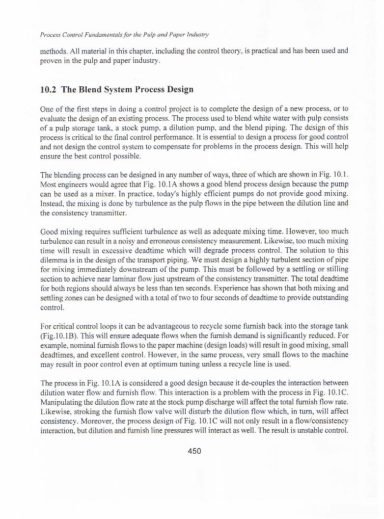
The blending process can be designed in any number of ways, three of which are shown in Fig. 10.1.Most engineers would agree that Fig. 1O.IA shows a good blend process design because the pumpcan be used as a mixer. In practice, today's highly efficient pumps do not provide good mixing.Instead, the mixing is done by turbulence as the pulp flows in the pipe between the dilution line andthe consistency transmitter.
Good mixing requires sufficient turbulence as well as adequate mixing time. However, too muchturbulence can result in a noisy and erroneous consistency measurement. Likewise, too much mixingtime will result in excessive deadtime which will degrade process control. The solution to thisdilemma is in the design of the transport piping. We must design a highly turbulent section of pipefor mixing immediately downstream of the pump. This must be followed by' a settling or stillingsection to achieve near laminar flow just upstream of the consistency transmitter. The total deadtimefor both regions should always be less than ten seconds. Experience has shown that both mixing andsettling zones can be designed with a total oftwo to four seconds of deadtime to provide outstandingcontrol.
For critical control loops it can be advantageous to recycle some furnish back into the storage tank(Fig. 10.1B). This will ensure adequate flows when the furnish demand is significantly reduced. Forexample, nominal furnish flows to the paper machine (design loads) will result in good mixing, smalldead times, and excellent control. However, in the same process, very small flows to the machinemay result in poor control even at optimum tuning unless a recycle line is used.
The process in Fig. 10.1A is considered a good design because it de-couples the interaction betweendilution water flow and furnish flow. This interaction is a problem with the process in Fig. 10.1C.Manipulating the dilution flow rate at the stock pump discharge will affect the total furnish flow rate.Likewise, stroking the furnish flow valve will disturb the dilution flow which, in turn, will affectconsistency. Moreover, the process design of Fig. 10.1C will not only result in a flow/consistencyinteraction, but dilution and furnish line pressures will interact as well. The result is unstable control.
450

Control Design: Intuition or Analysis?
In contrast, the pulp storage tank in Fig.l 0.2.1 A ensures a constant head at the pump suction. It isthis static head that de-couples the interactions described above. Consequently, blending shouldtypically be done immediately downstream from a storage tank at the pump suction.
PULPINVENTORY
DILUTION
A~ _
PULPINVENTORY
DILUTION
RECYCLE LINE
B~ _
WHITE aWATER
PULP ()JJ---c*J;------~SLURRY 2::d.
c~ _
Fig. 10.1. Design blend process for good control
The next step in process design is to ensure that all instrumentation, piping, and associated pumpsare properly sized and installed. It is necessary to follow all manufacturers' recommendations forstraight pipe runs upstream and downstream of each instrument. Many consistency transmittersrequire adequately sized piping to ensure the stock velocity does not exceed 3--4 ft./sec. These andother design and installation criteria are presented in Chapters 3 and 4.
We have used a very simple example of how to design a process for good control. The importantpoint is to spend adequate time to complete this task before the final process design is approved. Theresult will always yield a better process with less control variability. This often leads to improvedproduct quality, lower manufacturing costs, and increased productivity.
451

Process Control Fundamentals for the Pulp and Paper Industry
10.3 Control Design by Intuition
The final control design should be done concurrently with the process design for reasons discussedabove. Control and process engineers must work together. The intuitive approach to control designusually draws from an engineer's basic training and industrial experience. All too often, it involvespairing control variables (primary control elements) with manipulated variables (final controlelements) and inserting PID controllers. For example, to develop a consistency control method forthe process in Fig. IO.IA, the conventional and obvious approach is to use simple feedback as shownin Fig. 10.2. It is estimated that more than 95% of all consistency loops in the pulp and paperindustry use this control method.
DILUTION
FURNISH FLOW
Fig. 10.2. Typical feedback control loop
It is easy to identify potential disturbances in this loop and to add controls to compensate for thesedisturbances. For example, if the dilution pump supplies water to several different areas in the mill,the header pressure may vary as the total water demand varies. Consequently, this disturbance willaffect the dilution water flow (Fig. 10.2) which in tum will upset the consistency loop. Intuitively,we can solve this problem by adding a cascaded flow loop as shown in Fig. 10.3. In this case, theflow loop very quickly compensates for header pressure upsets to maintain the dilution flow atsetpoint. This helps avoid consistency variations.
Another disturbance to the loop in Fig. 10.2 can be caused by a change in pulp demand. Forexample, an increase in furnish flow will cause an increase in furnish consistency requiring thefeedback loop to raise the dilution flow. However, with feedback control alone, considerable timemay lapse before consistency is back on setpoint. Intuitively, we may regulate this load change muchfaster with feedforward control as shown in Fig. 10.4. With this configuration, a change in furnishflow will cause an immediate change in dilution flow that will compensate to keep the consistencyat setpoint. This, of course, assumes the feedforward loop is properly tuned.
452

Control Design: Intuition or Analysis?
DILUTION
SP_._._._.,I
~sp
FURNISH FLOW
Fig. 10.3. Typical cascade control loop
DILUTION
.B-spFig. 10.4. Control loop with feedforward and feedback trim
Finally, by combining the cascade and feedforward controls of Figs. 10.3 and 10.4, we would appearto have an excellent control method (Fig. 10.5) capable of handling all disturbances. However, thisis not the case. The intuitive approach has led us astray. There are many problems with the methodof Fig. 10.5.
First, ifthe feedback loop is precisely tuned for high performance at l,OOOGPM load, it will becomehighly unstable at 500 GPM and very slow responding at 2,000 GPM. The reasons for this problemwill be discussed later in this chapter. In addition, the dilution flow loop may not achieve its intendedfunction of stable control. Dilution header pressure variations can not be corrected simply by addinga flowmeter and closing the loop. This can make the problem even worse because each new flow
453

Process Control Fundamentalsfor the Pulp and Paper Industry
loop in the header becomes coupled with other flow loops elsewhere in the mill feeding from thesame pump. The result can be severe control loop interaction and unstable performance. Finally, thefeedforward control will not perform properly at any operating conditions other than those for whichit was tuned. For example, changes in the internal storage tank consistency, and even changes inconsistency setpoint will affect feedforward tuning. In addition, if a dilution flow loop is not used(e.g., Fig. 10.4), changes in pressure drop across the dilution valve will impact feedforward tuning.Moreover, if the installed flow characteristic of the valve is nonlinear, then changes in valve positionwill also affect feedforward tuning.
DILUTION
B-spFURNISH
FLOWFig. 10.5. Control loop with feedforward and cascaded feedback trim
Using intuition, we have added the cascaded flow loop in Fig. 10.5. This is a clear case of usingunnecessary controls to try to compensate for problems in the process design. Large pressurevariations in the dilution header is a result of an undersized pump. Pumps which service more thanone important control loop should be sized to operate on or near the flat part of the total head pumpcurve. This eliminates most of the pressure swings and avoids the control loop interaction discussedabove.
Clearly, the intuitive approach has failed us. How, then, do we design for good control?
10.4 Control Design by Analysis
The material and energy balance equations for any process provide insight into how that processshould be controlled. To illustrate the systems approach to control system design, we will discusstwo analogous processes: consistency (the blending of pulp and water) and temperature (theblending of a hot and a cold process stream).
454

Control Design: Intuition or Analysis?
10.4.1 Consistency
The first step in our analysis is to write the material balance equations for the consistency processin Fig. 10.1A. These consist of an overall flow balance and a fiber balance:
(1)
(2)
Where:FI, N] = Inventory flow and consistency (before dilution)Fo, No = Dilution flow and consistencyFF,NF = Furnish flow and consistency (after dilution).
The next step is to rearrange and combine these equations in a very special way that will reveal muchabout the process in terms of its control. We must solve these equations for the controlled variable(NF) as a function of variables we can manipulate and variables we can measure or calculate fromfield instrument data. A good starting point is to brainstorm a list of these independent variables sowe know which ones are desirable in the final equation. For our simple blend process, the list mayinclude Fo, FF,and N". We selected Fo and FF since they both can be measured directly using fieldinstrumentation. We also selected N1 since it can be indirectly determined using a material balanceequation and data from field devices.
The process of combining and rearranging equations can be time consuming. There are manyvariations of the equations, but only one most clearly defines the control needs. The process offinding this equation should not be rushed. It can take considerable effort, especially when theprocess is complex with many material and energy balance equations. However, for our simple blendprocess, Eqs. 1 and 2 yield the following:
(3)
If we substitute R for the ratio Fo/FF and assume the dilution water consistency ~ ) is 0.0, theequation simplifies:
= -RN + NJ J (4)
455

Process Control Fundamentals/or the Pulp and Paper Industry
We now have a relationship equating the process variable that we wish to control (dependentvariable) to several independent variables. The next step is to select one of the independent variablesto use as the manipulated variable in the control loop. The ratio of dilution flow to furnish flow, R,is the obvious choice for our blend process (Eq. 4). Typically, we cannot manipulate N1, the onlyother independent variable in the equation.
In summary, the material balance indicates that we should manipulate the setpoint of a ratiocontroller in order to properly regulate consistency (Fig. 10.6). When a control system is designedfrom the process material and energy balance equations, it is said to be consistent with the processand usually provides good control over a broad range of operation. It is interesting that this methodof control was omitted during our design by intuition. Unfortunately, this has been the case forconsistency control in the pulp and paper industry for many years.
DILUTION
FT - - - - - -,RATIO
CONTROLLER
Fig. 10.6. Typical ratio control loop in a mixing process
There are several reasons why Fig. 10.6-is a better method-of-control than-the methods discussedearlier. First, the ratio loop has an element of feedforward control that does not require tuning. Asthe furnish flow changes by a given amount, the dilution flow will also change by the samepercentage (e.g., doubling the furnish flow will feedforward to immediately double the dilutionflow). This will keep furnish consistency constant regardless of changes in furnish flow. Therefore,we have eliminated all interaction over the entire range of furnish flow. Recall that the feedforwardstrategy in Fig. 10.4 requires tuning that only performs well over a very narrow range of operation.This control method was developed by intuition and therefore is not consistent with the processmaterial balance equations. Another advantage ofthe controls in Fig. 10.6 is they maintain a constantprocess gain, even over a wide range of process load. We have defined the steady-state process gainas the rate of change in controlled variable per change in manipulated variable (L\ process output! L\process input). This is easily determined by differentiating the material balance (Eq. 4):
456

1
Control Design: Intuition or Analysis?
= -N/ (5)
The process gain, therefore, is only a function of the consistency inside the storage tank, and formany pulp and paper processes this is reasonably constant. It is important to maintain constant gainsin the control loop. This helps keep the amount of maintenance for controller tuning to a minimumand preserves loop stability at all process loads (e.g., process gain does not vary with FF)'
In contrast, all of the control methods designed by intuition (Fig. 10.2 through 10.5) directlymanipulate dilution flow (FD). In these cases, we differentiate Eq. 3 with respect to FD to obtain theprocess gam:
= (6)
Here, we find the process gain is inversely proportional to furnish flow. This means the controllergain must be retuned each time a significant change is made to FF' For example, if the consistencyloop is well tuned for a 1,000 GPM load, the controller gain must be reduced by 50% when the loadis changed to 500 GPM to maintain the same level of stability. If this change in controller gain is notmade, the loop will go unstable. Likewise, if the load is increased from 1,000 GPM to 2,000 GPM,the controller will become sluggish and slow responding. In this case, the controller gain must bedoubled to maintain the same degree of stability.
In summary, the control method of Fig. 10.6 is consistent with the process. By designing this systemfrom material balance equations, we have compensated for most of the control loop disturbances,solved the problem of process gain changes with furnish flow, and resolved the problem ofinteraction between furnish flow and consistency.
10.4.2 Energy
It is not obvious that the consistency (mass) process described above is analogous to a temperature(energy) process. On the surface, consistency and temperature control appear to be entirely different.However, when we realize that both processes fall into the general category of blending, the analogybecomes more clear. One process blends dilution water with pulp, while the other blends a hotprocess stream and a cold process stream. When we do the material and energy balance for thetemperature process (Fig. 10.7), the analogy to the consistency process is obvious.
457

Process Control Fundamentals for the Pulp and Paper Industry
Where:FH,THFe, TeFw,Tw
= Hot process stream flow and temperature= Cold process stream flow and temperature= Mixed process stream flow and temperature.
::::::::::::=::;.;.:::.:.;.: .
Fig. 10.7. Energy process mixing analogy
(7)
(8)
These equations-are- directly-analogous-to-Eqs.-l and-2:--Temperature-irrthe energy process isanalogous to consistency in the mass process. We can now rearrange and combine these equationsas was done for the mass process:
Next, we can substitute R for the ratio FelFw and aT for TH - Tc:
458
(9)
(10)

Control Design: Intuition or Analysis?
Notice we are not able to make the simplifying assumption Tc = 0.0 as we did with the analogousvariable of the mass process (i.e., No = 0.0). Finally, if we again select R as the manipulated variablefor temperature control, we can obtain the process gain by differentiating Eq. 10:
= -sr (11 )
Consequently, the process gain is only a function of LlT and not Fw. Therefore, load changes willnot affect controller tuning, however, large changes in LlT will, just as changes in N, will affecttuning of the consistency loop.
There are many analogous blend processes in the pulp and paper industry. Although each may havea different controlled variable, they are all very similar from a control perspective. Regardless of theapplication, the systems approach to control design using mass and/or energy balance equationsshould always be used to confirm intuitive designs.
10.5 Applications
We can now answer the questions posed in the introduction of this chapter. Which control methodfor blending is best? Which is the most cost effective? How do we determine which method to usefor a specific application? The best way to answer these questions is to first eliminate all the controlstrategies that have no significant value in blending.
We will start with the feedforward method of Fig. 10.4. This approach of summing a feedforwardsignal to the control output of a feedback loop is commonly used in all industries. Unfortunately, thiscontrol method is not consistent with any real process in pulp and paper or any other industry (i.e.,it does not conform to the mass and energy balance of any process). Consequently, the controls inFig. 10.4 have no place in blending and should be limited to processes where all else fails. Otherproblems with this configuration have already been discussed in this chapter.
Next, we can rule out using the controls in Fig. 10.5 (cascaded feed forward) for all the same reasons.In addition, the instrumentation required in Fig. 10.5 is identical to that used for ratio control (Fig.10.6). Since there is no cost incentive, the ratio configuration is preferred over cascaded feedforwardbecause it provides much better control.
This leaves us with a choice between the control methods of Figs. 10.2, 10.3, and 10.6. Simplefeedback is the most cost effective and most commonly used method (Fig. 10.2). It can be appliedto applications where tight blend control is not important. It is also the best choice for processes thatrun at constant load. For example, controlling machine chest consistency with a constant flow to the
459

Process Control Fundamentals/or the Pulp and Paper Industry
stuffbox is best done using simple feedback control. In this case, there is no load change and puttinga flow or ratio loop on the dilution line will not improve control. The additional loop, however, cancause unnecessary flow oscillations which will directly translate into basis weight variations on thepaper machine. It is also important to use a dedicated dilution pump for stuff box consistency controlto eliminate header pressure disturbances.
Next, the cascade control method in Fig.1 0.3 may have a few limited applications in processes whereone of the blend streams experience large deviations in header pressure. This is usually the result ofmanual load changes on a pump that is undersized. In this case, care should be taken to avoid controlloop interaction between multiple flow loops on the same header. Also note that the instrumentationrequired for cascade control is only one flowmeter short of that required for the much better ratiocontrol in Fig. 10.6.
Finally, the additional cost for instrumentation needed in Fig. 10.6 (ratio method) can only bejustified for critical applications requiring very tight blend control. Consistency controls for papermachine dry stock blending (Dumdie, 1988) and for the pulp mill pressure screen feed (Dumdie,1991) are two examples. In addition, the ratio method may be necessary in applications with largeload changes to ensure loop stability and fast response at all loads.
References
Dumdie, D. P.,"A systems approach to consistency control and dry stock blend", Tappi 71(7):135( 1988).
Dumdie, D. P.,"A systems approach to pressure screen control in the pulp mill", Tappi 74(11):97(1991).
460