proc imeche part j: some fundamental aspects of self
TRANSCRIPT
Special Issue Article
Some fundamental aspects ofself-levitating sliding contact bearingsand their practical implementations
MA Atherton, C Mares and TA Stolarski
Abstract
In this study, fundamental aspects and mechanisms of acoustic levitation together with governing equations are presented
first. Then, the acoustic levitation phenomenon is considered as a new way to design air suspension systems capable of
self-levitation. A particular emphasis is laid on journal bearings and their specific geometrical configuration. A practical
feasibility of using acoustic levitation to separate contacting surfaces is supported and illustrated by results of experi-
mental testing of a number of prototype devices.
Keywords
Self-levitation, squeeze-film action, journal bearing, linear bearing, experimental validation
Date received: 10 July 2013; accepted: 26 November 2013
Introduction
In non-contact bearings, there is no direct physicalcontact between interacting surfaces. Consequently,these bearings have no wear, almost no friction(except for fluid drag) and they can achieve higheraccuracies than conventional rolling-element bear-ings. Fluid film bearings are the most popular non-contact bearings, whereby a thin film of fluid (liquidor gas) is used to separate the two surfaces. The load-carrying capacity is derived from the pressure withinthe lubricating film, which can be generated by themotion of the bearing surfaces (self-acting or hydro-dynamic/aerodynamic bearings) or by external pres-surisation (hydrostatic, or aerostatic) or squeezemotion (squeeze film acoustic bearing, the mainfocus of this paper), or by a combination of theseactions. In addition to fluid film bearings, magneticbearings are another type of non-contact bearing,which support a load using magnetic levitationforce, without the need for a lubricant or separatingmedium.
Besides existing types of non-contact bearings,acoustic levitation has been used more generally as ameans of non-contact suspension of particles. Anacoustic wave can exert a force on objects immersedin the wave field and these forces are normally weakbut they can become quite large when using high fre-quency (ultrasonic) and high intensity waves. Whenthese forces are large enough to suspend substances
against gravity force then this phenomenon is calledacoustic levitation, and since the sound waves usedare often in the ultrasonic frequency range (higherthan 20 kHz), it is more often called ultrasoniclevitation.
Ultrasonic levitation was first used for levitatingsmall particles by creating a standing wave fieldbetween a sound radiator and a reflector, namelystanding wave ultrasonic levitation. Standing wavetype ultrasonic levitators with various features weredesigned for applications in different scientific discip-lines such as container-less material processing andspace engineering.1 Another well-known type of ultra-sonic levitation is squeeze film ultrasonic levitation,typically where a flat surface is brought to a confor-mal radiation surface which vibrates at high fre-quency. The basic theory underlying the operatingprinciple of ultrasonic levitation together with exam-ples of design embodiments of sliding contacts utilis-ing squeeze-film ultrasonic levitation are presented inthis paper.
Department of Mechanical Engineering, School of Engineering and
Design, Brunel University, Uxbridge, UK
Corresponding author:
TA Stolarski, Department of Mechanical Engineering, School of
Engineering and Design, Brunel University, Kingston Lane, Uxbridge,
Middlesex UB8 3PH, UK.
Email: [email protected]
Proc IMechE Part J:
J Engineering Tribology
2014, Vol. 228(9) 916–927
! IMechE 2014
Reprints and permissions:
sagepub.co.uk/journalsPermissions.nav
DOI: 10.1177/1350650113517110
pij.sagepub.com
Fundamentals of ultrasonic levitation
Standing wave levitation
The standing wave levitation phenomenon was firstobserved in Kundt’s tube experiment,2 in whichsmall dust particles moved towards the pressurenodes of the standing wave created in a horizontal(Kundt’s) tube. Multiple reflections between an ultra-sonic radiator and a solid, flat or concave reflector,generate a standing wave with equally spaced nodesand anti-nodes of the sound pressure and velocityamplitude. Solid or liquid samples with effective diam-eters less than a wavelength can be levitated belowthese pressure nodes and so the axial suspension ofthe sample is an effect of the sound radiation pressurein a standing wave. In addition, when combined witha Bernoulli vacuum component, the sound wave canlocate the samples laterally as well.3
The first detailed theoretical description of stand-ing wave levitation was given by King,4 which wasextended by Hasegawa and Yosioka5 to include theeffects of compressibility. Embleton6 adopted King’sapproach to fit to the case of a rigid sphere ina progressive spherical or cylindrical wave field.Westervelt7–9 derived a general expression for theforce owing to radiation pressure acting on anobject of arbitrary shape and normal boundaryimpedance, and also showed that a boundary layerwith a high internal loss can lead to forces that areseveral orders of magnitude greater than those pre-dicted by the classical radiation pressure theory.
Gorkhov10 presented a very different approach toKing, using a simple method to determine the forcesacting on a particle in an arbitrary acoustic field, inwhich the velocity potential was represented as sumof an incident and a scattered term. Barmatz11
applied Gorkhov’s method to derive the generalisedpotential and force expressions for arbitrary stand-ing wave modes in rectangular cylindrical andspherical geometries. Lierke12 gave an overview ofstanding wave acoustic levitation based on long-term research and development activities of theEuropean and the US space agencies. Xie andWei13 studied the acoustic levitation force on disksamples and the dynamics of large water drops in aplanar standing wave, by solving the acoustic scat-tering problem through incorporating the boundaryelement method.
The theoretical approach of King4 is presentedbelow for understanding the basic working principlesof standing wave levitation. Assuming that the work-ing fluid is adiabatic and barotropic, the equations ofmotion can be written as
�Du
Dt¼ �
@p
@x, �
Dv
Dt¼ �
@p
@y, �
Dw
Dt¼ �
@p
@zð1Þ
where DDt ¼
@@tþ u @
@xþ v @@yþ w @
@z is the absolutederivative, � the density of the medium, p the
pressure and (u, v,w) the Cartesian velocitycomponents.
By defining $ ¼ dp�� the equation of motion can
be rewritten as
Du
Dt¼ �
@$
@x,Dv
Dt¼ �
@$
@y,Dw
Dt¼ �
@$
@zð2Þ
When the motion is non-rotational, the velocity com-ponents can be expressed in terms of the velocitypotential �
ðu, v,wÞ ¼ �r� ð3Þ
In the case where air is the medium, the velocitypotential can be obtained from the approximatelinear wave equation
r2� ¼1
c2@2�
@t2ð4Þ
which is simplified from the exact differential equationfor � using a second-order approximation. The equa-tion of continuity is
@�
@tþ@
@xð�uÞ þ
@
@yð�vÞ þ
@
@zð�wÞ ¼ 0 ð5Þ
and the pressure variation can then be derived fromequation (5) as
�p ¼ p� p0 ¼ p0@�
@tþ1
2
�0c2
@�
@t
� �2
�1
2�0q
2 ð6Þ
where �0 is the density of the surrounding medium, �is the velocity potential, c is the sound speed in air andq is the velocity amplitude equal to
ffiffiffiffiffiffiffiffiffiffiffiffiffiffiffiffiffiffiffiffiffiffiffiffiffiffiu2 þ v2 þ w2p
.Detailed derivation of equation (6) can be found inKing.4 The time-averaged acoustic pressure on a rigidbody can be calculated by integrating the acousticpressures acting on each surface element of thebody. In the case of a plane standing wave, the vel-ocity potential �s can be expressed as4
�s ¼ Aj j cos kh cos!t ð7Þ
where jAj is the amplitude of the velocity potential,k¼ 2p/� is the wave number and h is the positionwhere the sphere, which is assumed to be small, islocated. The acoustic radiation force on a rigidsphere can be calculated as
F ¼ �5
6��0 Aj j
2ðkRsÞ3 sinð2khÞ ð8Þ
with Rs being the radius of the sphere.Bucks and Muller14 presented the first experimen-
tal setup for positioning of small samples in acousticstanding waves, in which a small particle was trapped
Atherton et al. 917
at a position slightly below the pressure nodes of thestanding wave between a radiator and a reflector.Wang et al.15 presented an acoustic chamber for pos-itioning of molten materials in an extreme tempera-ture gradient. Whymark16 proposed an acousticlevitator for positioning of materials in space usinga single source of sound that achieved fine positioncontrol by adjusting the reflector. Lierke17 presentedan acoustic levitator for positioning materials samplesin mirror furnaces when processing in space. Trinh18
presented a compact acoustic levitation device formicrogravity studies of fluid dynamics and materialsscience. This classic structure was later modified toachieve better performance. Otsuka et al.19 used astepped circular vibrating plate as a radiator for pro-ducing high-intensity ultrasound fields which was dif-ferent from conventional piston-like vibration sourcesin using the flexural vibration mode of the plate withtwo nodal rings to achieve higher vibration amplitude.The stepped plate has a concave channel with fixeddepth equal to the half sound wavelength in air. Thisspecial design makes the concave and convex blocksvibrate in the counter phase so that the ultrasoundpropagating in the air is modulated in the samephase. As a result, a narrow, intensive, high direc-tional ultrasound beam is obtained. Xie and Wei20
enhanced the standing wave acoustic levitation forceby properly curving the surface and enlarging thereflector and thus high density material, e.g. tungsten,was successfully levitated for the first time usingstanding wave ultrasonic levitation. Recently Xieand Wei21 reported the successful levitation of smallliving animals such as an ant, ladybird and small fishwith a standing wave acoustic levitator and theirexperiments showed that the vitality of the small ani-mals was not impaired during levitation.
All the standing wave levitation systems presentedabove possessed the classic radiator-reflector config-uration and so applications of such configurationwere limited to the levitation of small particleswhose dimension does not exceed the wavelength ofthe imposed sound wave. Moreover, the levitationforce obtainable from this configuration is very lim-ited and therefore modifications and improvementsare needed before standing wave ultrasonic levitationcan be applied in non-contact suspension systemssuch as linear and rotational bearings.
Squeeze-film ultrasonic levitation
Salbu22 reported a levitation system for objects withflat surfaces that used magnetic actuators to excitetwo conforming surfaces oscillating next to eachother to generate a positive load-supporting force.In 1975, Whymark16 reported that a brass planardisk of 50mm in diameter and 0.5mm in thicknesswas levitated extremely close to a piston vibrationsource driven harmonically at a frequency of20 kHz. These levitation effects reported by Salbu
and Whymark were named as squeeze-film levitationand also called near-field acoustic levitation.
A schematic diagram of squeeze-film levitationsystem usually consists of two parallel plates sepa-rated by an air film of thickness h0. The time-averagedmean pressure in the gap has a value which is higherthan the surroundings, which is caused by the second-order effects possessed by the rapidly squeezed andreleased gas film between two plane surfaces. Twodistinct properties distinguish this type of levitationfrom standing-wave levitation. First, the reflector isno longer needed; instead, the levitated object itselfacts as an obstacle for the free propagation of theultrasonic wave-front. Second, the gap between radi-ation source and the levitated object must be muchsmaller than the sound wavelength in air. Thus,instead of a standing wave, a thin gas film is formedbetween the radiator and the levitated object, which israpidly squeezed and released. A simple model intro-duced by Wiesendanger23 is presented here to demon-strate the basic idea of how squeeze-film levitationworks. The leaking and pumping at the boundary isneglected in this model, thus only the trapped gas thatis rapidly squeezed and released is considered. Thetotal mass of air in a fixed volume remains constant,resulting in
pVn � phn ¼ const ð9Þ
where p represents the pressure, V the volume of thetrapped gas, h the gap distance for a one-dimensionalcontact and n the polytropic constant (n¼ 1 for iso-thermal condition, n¼ k& 1.4 for an adiabatic condi-tion of air). The relation between pressure andlevitation distance is nonlinear, which leads to a dis-torted pressure pðtÞ resulting from the imposed peri-odic gap distance h(t). The gap distance (air filmthickness) oscillates harmonically around a equilib-rium position, h0, i.e.
hðtÞ ¼ h0ð1þ " sin!tÞ ð10Þ
in which ! is the angular frequency of the oscillation," the excursion ratio ð" ¼ a0=h0Þ. The excursion ratiodenotes the ratio of the vibration amplitude over themean gap distance, where a0 is the vibration displace-ment amplitude. The mean pressure under isothermalconditions (n¼ 1) can be expressed as in23
�p ¼p0h02�
Z2�
0
1
hðtÞdð!tÞ ¼
p0ffiffiffiffiffiffiffiffiffiffiffiffiffi1� "2p ð11Þ
It can be easily seen that mean pressure �p exceeds theambient pressure, p0. The harmonic motion of theradiating surface produces a non-harmonic pressure
918 Proc IMechE Part J: J Engineering Tribology 228(9)
oscillation whose mean value is not equal to the quasi-static value, p0. The positive mean pressure �p is largerthan the ambient pressure, p0, which is a qualitativeconfirmation of the existence of a levitation pressure.However, to obtain a quantitative value of the levita-tion pressure, more sophisticated models are neededwhich take into account the boundary conditions suchas the pressure release at the edge of the gap. Such amodel of squeeze-film levitation can be established byfollowing two different routes: acoustic radiationpressure theory and gas film lubrication theory. Thefirst one modifies the acoustic radiation pressuretheory according to the different physical conditionsin squeeze-film levitation. The second one starts fromthe theory of gas film lubrication since the workingprinciple is actually similar.24,25 Gas film lubricationhas been investigated for many years in micro-mechanical systems commonly by solving Reynoldsequation.
A simplified equation for the radiation pressure insqueeze-film acoustic levitation was derived from theacoustic radiation pressure theory presented by Chuand Apfel26 by Hashimoto et al.27 They calculated theRayleigh radiation pressure in an ideal gas on a per-fectly reflecting target as
p ¼ P� P0h i ¼1þ �
21þ
sinð2khÞ
2kh
� �Eh i ð12Þ
Here, E is the energy density which can be expressedas
E ¼a204
� ��0!
2
sin2ðkhÞ
� �ð13Þ
in which k represents the wave number, � a specificheat ratio, ! the angular velocity of the wave, a0 thevibration amplitude and h the distance between vibra-tion source and target. In squeeze film levitation, thelevitation distance is very small compared to thewavelength of sound in the free field. It ranges fromseveral to several tens micrometers, therefore in equa-tion (12) sin kh � kh was simplified to a linear equa-tion for the radiation pressure in squeeze filmlevitation
� ¼1þ �
4�0c
2 a20
h2ð14Þ
The radiation pressure, �, in squeeze film levitation isinversely proportional to the square of the levitationdistance and proportional to the square of the vibra-tion amplitude a0. Hashimoto et al. did experimentsto verify equation (14) and the results for maximumlevitation force were 25% lower than those calculatedfrom equation (14). The authors put this discrepancydown to the finite dimensions of the surfaces and thenon-uniformity of the amplitude of the radiationsurface.
Wiesendanger23 also used gas film lubricationtheory24,25 and solved the general Reynolds equationboth analytically and numerically to achieve quanti-tative results for the levitation forces. Nomura andKamakura28 theoretically and experimentally exam-ined squeeze-film acoustic levitation by numericallysolving the basic equations of a viscous fluid usingMacCormack’s finite-difference scheme and includingviscosity and acoustic energy leakage in the model.Minikes29 studied the levitation force induced by pres-sure radiation in gas squeeze films, investigating theflow induced both by vibrations perpendicular to aflat surface and by a flexural wave propagating paral-lel to the surface. For the first case, numerical andsecond-order analytical perturbation solutions werecompared and proved to be in good agreement toeach other. For the second case, a modifiedReynolds equation was derived to obtain the pressuredistribution and the velocity profile in the film inorder to determine the reaction forces. Later,Minikes30 examined the validity of the pressurerelease boundary condition and the isothermalassumptions through a CFD scheme. By comparinghis results to a one-dimensional analytical solution,Minikes found that the levitation force reduced to ahalf when the energy leakage near the edges of thelevitated object were taken in to account. This indi-cates that the assumption of pressure release at theboundaries, implied in the Reynolds equation, is inad-equate in cases where the driving surface is signifi-cantly larger than the levitated surface.
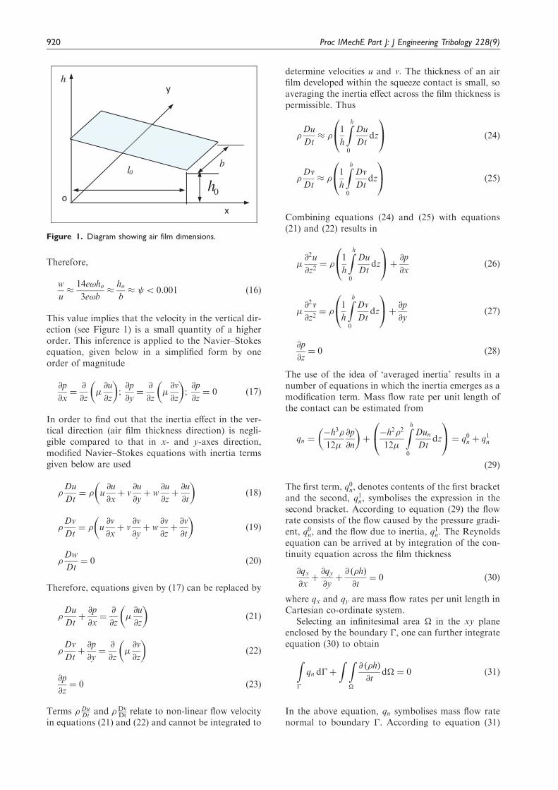
Squeeze-film ultrasonic levitationwith inertia effect
In depth analysis of the significance of inertia effect insqueeze-film pressure generation was carried out byStolarski and Chai,31 based on the Reynolds equationmodified to include an inertia effect. Therefore, inorder to avoid unnecessary repetition, only selectedequations are presented here as a comprehensivetreatment of the problem is given elsewhere.31 In thecase of a linear bearing configuration (discussed inmore details later), air film geometry can be repre-sented as in Figure 1. Cyclic movement e sinð!tÞ inthe vertical direction (z-axis) generates a characteristicair velocity given by w � e!, where w is flow velocityof air in z direction, e is the amplitude of vibration ofa squeeze surface produced by a piezoelectric actu-ator, and ! denotes angular velocity of the squeezesurface rotation. The order of magnitude of the aver-age flow rate Q due to squeeze action over all theboundaries can be determined, approximately, fromthe expression below (for derivation details seeStolarski and Chai31)
u �3Q
14loho¼
3wlob
14loho¼
3wb
14ho¼
3e!b
14hoð15Þ
Atherton et al. 919
Therefore,
w
u�
14e!ho3e!b
�hob� 5 0:001 ð16Þ
This value implies that the velocity in the vertical dir-ection (see Figure 1) is a small quantity of a higherorder. This inference is applied to the Navier–Stokesequation, given below in a simplified form by oneorder of magnitude
@p
@x¼@
@z�@u
@z
� �;@p
@y¼@
@z�@v
@z
� �;@p
@z¼ 0 ð17Þ
In order to find out that the inertia effect in the ver-tical direction (air film thickness direction) is negli-gible compared to that in x- and y-axes direction,modified Navier–Stokes equations with inertia termsgiven below are used
�Du
Dt¼ � u
@u
@xþ v
@u
@yþ w
@u
@zþ@u
@t
� �ð18Þ
�Dv
Dt¼ � u
@v
@xþ v
@v
@yþ w
@v
@zþ@v
@t
� �ð19Þ
�Dw
Dt¼ 0 ð20Þ
Therefore, equations given by (17) can be replaced by
�Du
Dtþ@p
@x¼@
@z�@u
@z
� �ð21Þ
�Dv
Dtþ@p
@y¼@
@z�@v
@z
� �ð22Þ
@p
@z¼ 0 ð23Þ
Terms � DuDt and �Dv
Dt relate to non-linear flow velocityin equations (21) and (22) and cannot be integrated to
determine velocities u and v. The thickness of an airfilm developed within the squeeze contact is small, soaveraging the inertia effect across the film thickness ispermissible. Thus
�Du
Dt� �
1
h
Zh
0
Du
Dtdz
0@
1A ð24Þ
�Dv
Dt� �
1
h
Zh
0
Dv
Dtdz
0@
1A ð25Þ
Combining equations (24) and (25) with equations(21) and (22) results in
�@2u
@z2¼ �
1
h
Zh
0
Du
Dtdz
0@
1Aþ @p
@xð26Þ
�@2v
@z2¼ �
1
h
Zh
0
Dv
Dtdz
0@
1Aþ @p
@yð27Þ
@p
@z¼ 0 ð28Þ
The use of the idea of ‘averaged inertia’ results in anumber of equations in which the inertia emerges as amodification term. Mass flow rate per unit length ofthe contact can be estimated from
qn ¼�h3�
12�
@p
@n
� �þ�h2�2
12�
Zh
0
DunDt
dz
0@
1A ¼ q0n þ q1n
ð29Þ
The first term, q0n, denotes contents of the first bracketand the second, q1n, symbolises the expression in thesecond bracket. According to equation (29) the flowrate consists of the flow caused by the pressure gradi-ent, q0n, and the flow due to inertia, q1n. The Reynoldsequation can be arrived at by integration of the con-tinuity equation across the film thickness
@qx@xþ@qy@yþ@ ð�hÞ
@t¼ 0 ð30Þ
where qx and qy are mass flow rates per unit length inCartesian co-ordinate system.
Selecting an infinitesimal area � in the xy planeenclosed by the boundary �, one can further integrateequation (30) to obtain
Z�
qn d�þ
Z Z�
@ ð�hÞ
@td� ¼ 0 ð31Þ
In the above equation, qn symbolises mass flow ratenormal to boundary �. According to equation (31)
y
o
h
x
0h l0
b
Figure 1. Diagram showing air film dimensions.
920 Proc IMechE Part J: J Engineering Tribology 228(9)
the mass flow rate through the boundary � is equal tothe mass reduction rate in the domain �.Involving the inertia effect contained in equation(29) with equation (31) leads to a boundary integralequation of the form
Z�
q0n þ q1n� �
d�þ
Z Z�
@ ð�hÞ
@td� ¼ 0 ð32Þ
Examples of design embodimentsof self-levitating sliding contacts
This paper is concerned with the important applica-tion of squeeze-film levitation to developing non-contact linear and rotational bearings. A number ofexamples of possible practical implementation of thefundamental principles of squeeze-film ultrasonic levi-tation are presented and briefly discussed in thissection.
Linear motion bearing
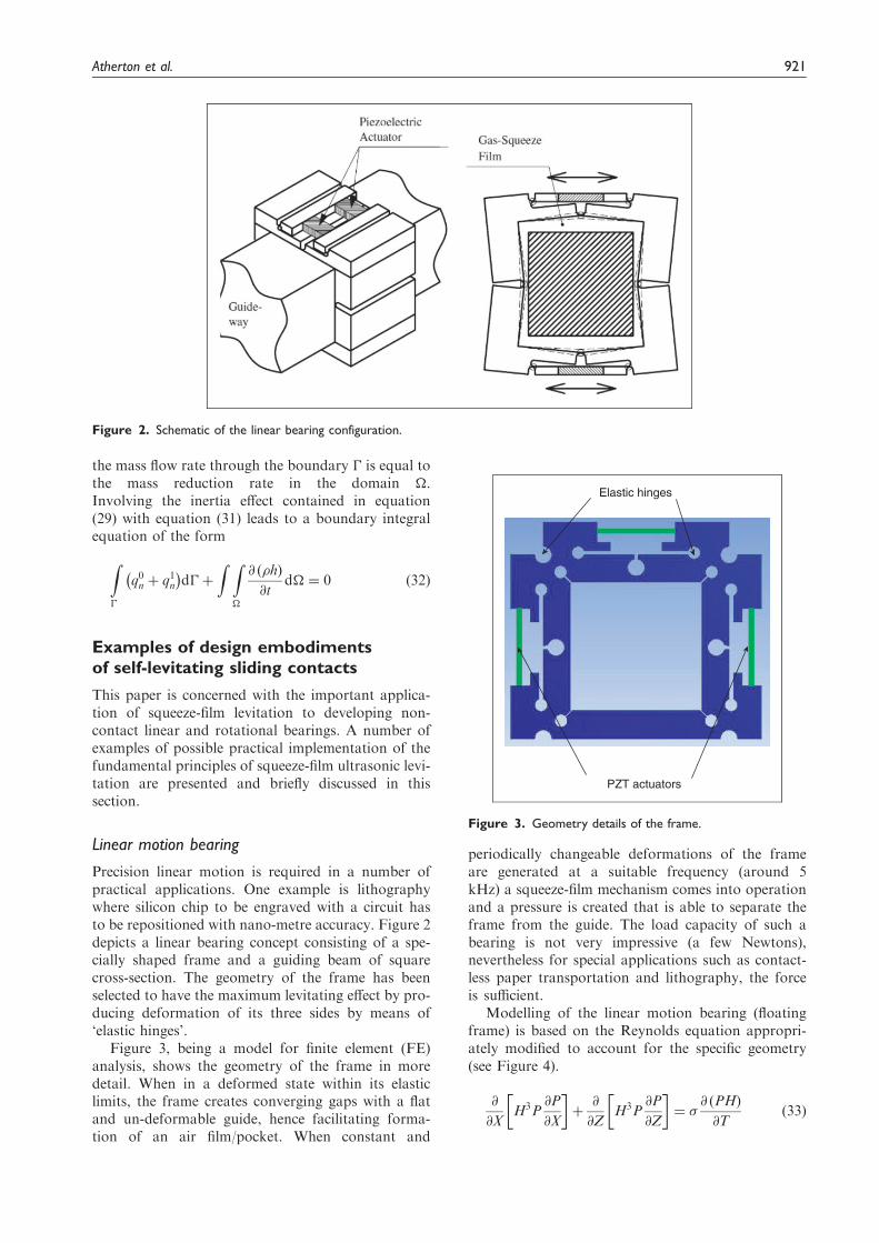
Precision linear motion is required in a number ofpractical applications. One example is lithographywhere silicon chip to be engraved with a circuit hasto be repositioned with nano-metre accuracy. Figure 2depicts a linear bearing concept consisting of a spe-cially shaped frame and a guiding beam of squarecross-section. The geometry of the frame has beenselected to have the maximum levitating effect by pro-ducing deformation of its three sides by means of‘elastic hinges’.
Figure 3, being a model for finite element (FE)analysis, shows the geometry of the frame in moredetail. When in a deformed state within its elasticlimits, the frame creates converging gaps with a flatand un-deformable guide, hence facilitating forma-tion of an air film/pocket. When constant and
periodically changeable deformations of the frameare generated at a suitable frequency (around 5kHz) a squeeze-film mechanism comes into operationand a pressure is created that is able to separate theframe from the guide. The load capacity of such abearing is not very impressive (a few Newtons),nevertheless for special applications such as contact-less paper transportation and lithography, the forceis sufficient.
Modelling of the linear motion bearing (floatingframe) is based on the Reynolds equation appropri-ately modified to account for the specific geometry(see Figure 4).
@
@XH3P
@P
@X
� þ@
@ZH3P
@P
@Z
� ¼ �
@ ðPHÞ
@Tð33Þ
Figure 2. Schematic of the linear bearing configuration.
PZT actuators
Elastic hinges
Figure 3. Geometry details of the frame.
Atherton et al. 921
where � is the squeeze number. Equation (33) can beexpanded to give
PH3 @2P
@X2þH3 @P
@X
� 2þ3PH2 @P
@X
@H
@X
þ PH3 @2P
@Z2þH3 @P
@Z
� 2þ3PH2 @P
@Z
@H
@Z
¼ �P@H
@Tþ �H
@P
@Tð34Þ
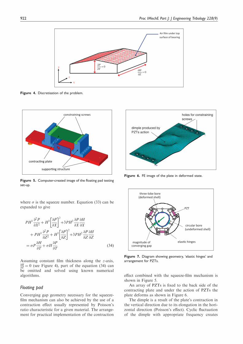
Assuming constant film thickness along the z-axis,@H@Z ¼ 0 (see Figure 4), part of the equation (34) canbe omitted and solved using known numericalalgorithms.
Floating pad
Converging gap geometry necessary for the squeeze-film mechanism can also be achieved by the use of acontraction effect usually represented by Poisson’sratio characteristic for a given material. The arrange-ment for practical implementation of the contraction
effect combined with the squeeze-film mechanism isshown in Figure 5.
An array of PZTs is fixed to the back side of thecontracting plate and under the action of PZTs theplate deforms as shown in Figure 6.
The dimple is a result of the plate’s contraction inthe vertical direction due to its elongation in the hori-zontal direction (Poisson’s effect). Cyclic fluctuationof the dimple with appropriate frequency creates
0=∂∂Y
P
x
z
y
0=∂∂
Z
H
Air film under top surface of bearing
Figure 4. Discretisation of the problem.
contrac�ng plate
suppor�ng structure
constraining screws
Figure 5. Computer-created image of the floating pad testing
set-up.
PZT
elas�c hinges
circular bore(undeformed shell)
three-lobe bore(deformed shell)
magnitude of converging gap
Figure 7. Diagram showing geometry, ‘elastic hinges’ and
arrangement for PZTs.
holes for constrainingscrews
dimple produced byPZTs action
Figure 6. FE image of the plate in deformed state.
922 Proc IMechE Part J: J Engineering Tribology 228(9)
conditions necessary for the squeeze-film operationand generation of pressure at the interface betweenthe plate and an object to be levitated.
Modelling of the floating pad for analysis purposestarts with determining the modes of the plate’sdeformation. Only those modes of deformation pro-ducing geometry favourable for the squeeze-filmmechanism should be selected. An easy way to carryout structural deformation analyses is to use finiteelement analysis.
Once the required geometry of deforming plate issecured, the squeeze-film effect equations can beemployed to determine pressure in the air film andhence load capacity of the floating pad.The effectiveness of squeeze-film ultrasonic levitationcan be assessed from
r½H3P � rP� ¼ �@ ðPHÞ
@Tð35Þ
In fact equation (35) is the Reynolds equation in non-dimensional variables, which are defined as follows
X ¼x
l0, Y ¼
y
l0, H ¼
h
h0, P ¼
p
pa, T ¼ !0t,
� ¼12!0l
20
pah20
Here H is the separation distance, P is the pressure, Tis the time, l0 is the lateral dimension of the pad, h0 isthe mean air film thickness, pa is the ambient air pres-sure, is the viscosity of air and � is the squeezenumber. The squeeze number is an important factor
in finding the load capacity of a bearing operatingwith squeeze-film ultrasonic levitation. Low s meansthat the air is simply flowing through the contactwithout undergoing compression and decompression.High s signifies a relatively stationary air filmundergoing cyclic compression and decompressionand hence contributing to the load capacity of thecontact.
Rotating motion bearing
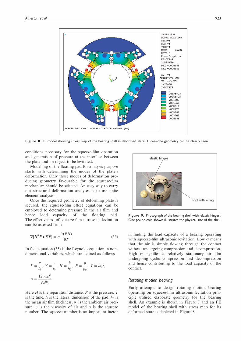
Early attempts to design rotating motion bearingoperating on squeeze-film ultrasonic levitation prin-ciple utilised elaborate geometry for the bearingshell. An example is shown in Figure 7 and an FEmodel of the bearing shell with stress map for itsdeformed state is depicted in Figure 8.
Figure 8. FE model showing stress map of the bearing shell in deformed state. Three-lobe geometry can be clearly seen.
PZT with wiring
elastic hinges
Figure 9. Photograph of the bearing shell with ‘elastic hinges’.
One pound coin shown illustrates the physical size of the shell.
Atherton et al. 923
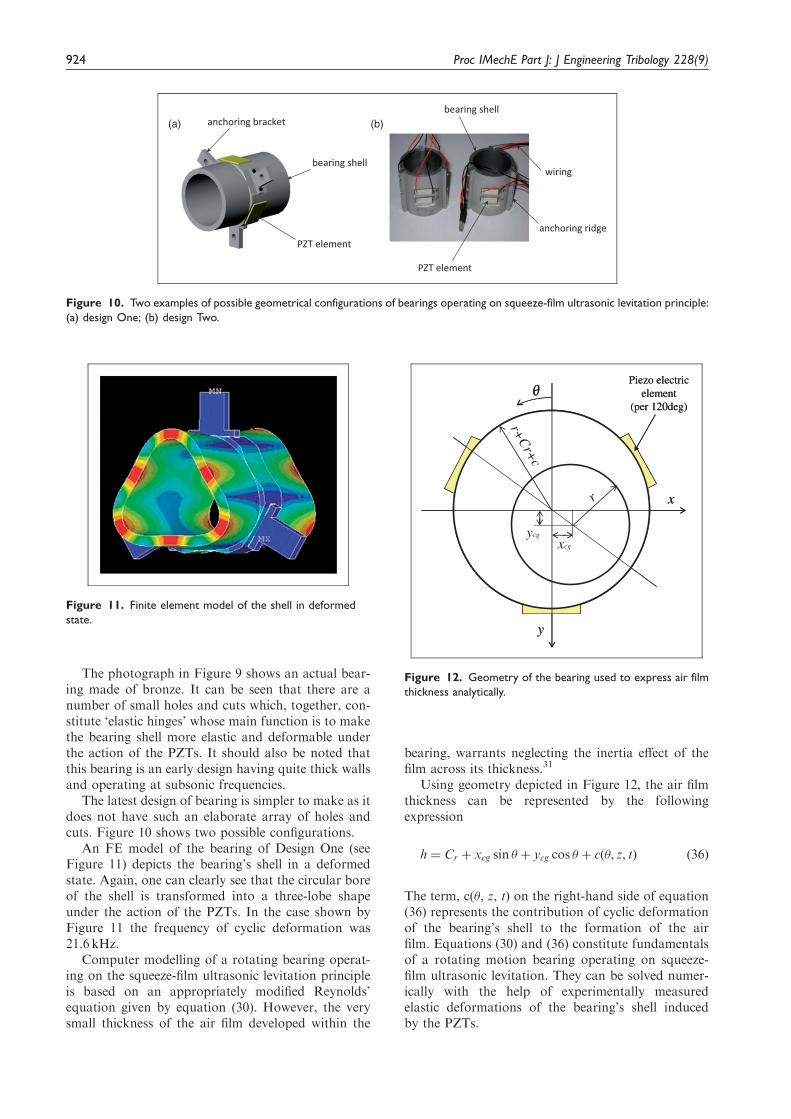
The photograph in Figure 9 shows an actual bear-ing made of bronze. It can be seen that there are anumber of small holes and cuts which, together, con-stitute ‘elastic hinges’ whose main function is to makethe bearing shell more elastic and deformable underthe action of the PZTs. It should also be noted thatthis bearing is an early design having quite thick wallsand operating at subsonic frequencies.
The latest design of bearing is simpler to make as itdoes not have such an elaborate array of holes andcuts. Figure 10 shows two possible configurations.
An FE model of the bearing of Design One (seeFigure 11) depicts the bearing’s shell in a deformedstate. Again, one can clearly see that the circular boreof the shell is transformed into a three-lobe shapeunder the action of the PZTs. In the case shown byFigure 11 the frequency of cyclic deformation was21.6 kHz.
Computer modelling of a rotating bearing operat-ing on the squeeze-film ultrasonic levitation principleis based on an appropriately modified Reynolds’equation given by equation (30). However, the verysmall thickness of the air film developed within the
bearing, warrants neglecting the inertia effect of thefilm across its thickness.31
Using geometry depicted in Figure 12, the air filmthickness can be represented by the followingexpression
h ¼ Cr þ xcg sin þ ycg cos þ cð, z, tÞ ð36Þ
The term, c(, z, t) on the right-hand side of equation(36) represents the contribution of cyclic deformationof the bearing’s shell to the formation of the airfilm. Equations (30) and (36) constitute fundamentalsof a rotating motion bearing operating on squeeze-film ultrasonic levitation. They can be solved numer-ically with the help of experimentally measuredelastic deformations of the bearing’s shell inducedby the PZTs.
anchoring bracket
PZT element
bearing shell
anchoring ridge
PZT element
wiring
bearing shell(a) (b)
Figure 10. Two examples of possible geometrical configurations of bearings operating on squeeze-film ultrasonic levitation principle:
(a) design One; (b) design Two.
xcg
ycg
θ
r+C
r+c
r
Piezo electric element
(per 120deg)
x
y
xcg
ycg
θ
r+C
r+c
r
Piezo electric element
(per 120deg)
x
y
Figure 12. Geometry of the bearing used to express air film
thickness analytically.
Figure 11. Finite element model of the shell in deformed
state.
924 Proc IMechE Part J: J Engineering Tribology 228(9)
Experimental confirmation of theconcepts
In order to demonstrate the feasibility of squeeze-filmultrasonic levitation preliminary experimental testingof design embodiments presented earlier was under-taken. Undoubtedly the most useful information, inview of potential practical applications, is the load-carrying capacity. Some selected results obtainedfrom preliminary experimental testing are presentedin this section.
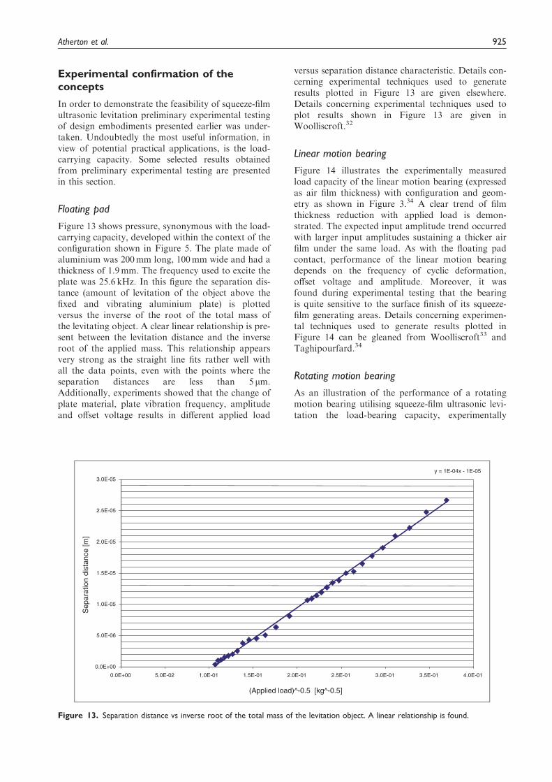
Floating pad
Figure 13 shows pressure, synonymous with the load-carrying capacity, developed within the context of theconfiguration shown in Figure 5. The plate made ofaluminium was 200mm long, 100mm wide and had athickness of 1.9mm. The frequency used to excite theplate was 25.6 kHz. In this figure the separation dis-tance (amount of levitation of the object above thefixed and vibrating aluminium plate) is plottedversus the inverse of the root of the total mass ofthe levitating object. A clear linear relationship is pre-sent between the levitation distance and the inverseroot of the applied mass. This relationship appearsvery strong as the straight line fits rather well withall the data points, even with the points where theseparation distances are less than 5 mm.Additionally, experiments showed that the change ofplate material, plate vibration frequency, amplitudeand offset voltage results in different applied load
versus separation distance characteristic. Details con-cerning experimental techniques used to generateresults plotted in Figure 13 are given elsewhere.Details concerning experimental techniques used toplot results shown in Figure 13 are given inWoolliscroft.32
Linear motion bearing
Figure 14 illustrates the experimentally measuredload capacity of the linear motion bearing (expressedas air film thickness) with configuration and geom-etry as shown in Figure 3.34 A clear trend of filmthickness reduction with applied load is demon-strated. The expected input amplitude trend occurredwith larger input amplitudes sustaining a thicker airfilm under the same load. As with the floating padcontact, performance of the linear motion bearingdepends on the frequency of cyclic deformation,offset voltage and amplitude. Moreover, it wasfound during experimental testing that the bearingis quite sensitive to the surface finish of its squeeze-film generating areas. Details concerning experimen-tal techniques used to generate results plotted inFigure 14 can be gleaned from Woolliscroft33 andTaghipourfard.34
Rotating motion bearing
As an illustration of the performance of a rotatingmotion bearing utilising squeeze-film ultrasonic levi-tation the load-bearing capacity, experimentally
y = 1E-04x - 1E-05
0.0E+00
5.0E-06
1.0E-05
1.5E-05
2.0E-05
2.5E-05
3.0E-05
0.0E+00 5.0E-02 1.0E-01 1.5E-01 2.0E-01 2.5E-01 3.0E-01 3.5E-01 4.0E-01
(Applied load)^-0.5 [kg^-0.5]
Sep
arat
ion
dist
ance
[m]
Figure 13. Separation distance vs inverse root of the total mass of the levitation object. A linear relationship is found.
Atherton et al. 925
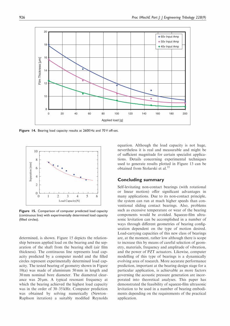
determined, is shown. Figure 15 depicts the relation-ship between applied load on the bearing and the sep-aration of the shaft from the bearing shell (air filmthickness). The continuous line represents load cap-acity predicted by a computer model and the filledcircles represent experimentally determined load cap-acity. The tested bearing of geometry shown in Figure10(a) was made of aluminium 50mm in length and30mm nominal bore diameter. The diametral clear-ance was 20 mm. A typical resonant frequency atwhich the bearing achieved the highest load capacitywas in the order of 30–35 kHz. Computer predictionwas obtained by solving numerically (Newton–Raphson iteration) a suitably modified Reynolds
equation. Although the load capacity is not huge,nevertheless it is real and measurable and might beof sufficient magnitude for certain specialist applica-tions. Details concerning experimental techniquesused to generate results plotted in Figure 13 can beobtained from Stolarski et al.35
Concluding summary
Self-levitating non-contact bearings (with rotationalor linear motion) offer significant advantages inmany applications. Due to its non-contact principle,the system can run at much higher speeds than con-ventional sliding contact bearings. Also, problemssuch as excessive temperature or wear of the bearingcomponents would be avoided. Squeeze-film ultra-sonic levitation can be accomplished in a number ofways through different geometries of bearing config-uration dependent on the type of motion desired.Load-carrying capacities of this new class of bearingsare, at the moment, rather low although there is scopeto increase this by means of careful selection of geom-etry, materials, frequency and amplitude of vibration,and the power of PZT actuators. Likewise, computermodelling of this type of bearings is a dynamicallyevolving area of research. More accurate performanceprediction, important at the bearing design stage for aparticular application, is achievable as more factorsgoverning the acoustic pressure generation are incor-porated into theoretical analyses. This paper hasdemonstrated the feasibility of squeeze-film ultrasoniclevitation to be used in a number of bearing embodi-ments depending on the requirements of the practicalapplication.
8
10
12
14
16
18
20
40 60 80 100 120 140 1600 20 180 200
Applied load [g]
Film
Thi
ckne
ss [µ
m]
60v Input Amp
50v Input Amp
40v Input Amp
Figure 14. Bearing load capacity results at 2600 Hz and 70 V off-set.
0 1 2 3 4 5 60
2
4
6
8
10
Load Capacity[N]
Sepa
ratio
n [m
m]
Figure 15. Comparison of computer predicted load capacity
(continuous line) with experimentally determined load capacity
(filled circles).
926 Proc IMechE Part J: J Engineering Tribology 228(9)
Funding
This work was partially supported by the Engineering and
Physical Sciences Research Council, UK (grant number EP/F04979X/1).
Conflict of interest
None declared.
References
1. Vandaele V, Lambert P and Delchambre A. Non-contact handling in micro assembly: Acoustical levita-tion. Precis Eng 2005; 29: 491–505.
2. Poynting JH and Thomson JJ. A textbook of physics.London: Charles Griffin & Co., 1904.
3. Daidzic N. Nonlinear droplet oscillations and evapor-
ation in an ultrasonic levitator. PhD Thesis, Friedrich-Alexander University, Erlangen, 1995.
4. King LV. On the acoustic radiation pressure on spheres.
Proc R Soc Ser A Lond 1934; 147: 212–240.5. Hasegawa T. Acoustic-radiation force on a solid elastic
sphere. Acoust Soc Am 1969; 46: 1139.6. Embleton TFW. Mean force on a sphere in a spherical
sound field. Acoust Soc Am 1954; 26: 40–48.7. Westervelt PJ. The mean pressure and velocity in a
plane acoustic wave in a gas. Acoust Soc Am 1950; 22:
319–327.8. Westervelt PJ. The theory of steady forces caused by
sound waves. Acoust Soc Am 1951; 23: 312–315.
9. Westervelt PJ. Acoustic radiation pressure. Acoust SocAm 1957; 29: 26–29.
10. Gorkhov LP. On the forces acting on a small particle inan acoustical field in an ideal fluid. Sov Phys Dokl 1962;
6: 773–781.11. Barmatz M and Collas P. Acoustic radiation potential
on a sphere in plane, cylindrical, and spherical standing
wave fields. Acoust Soc Am 1985; 77: 928–945.12. Lierke EG. Acoustic levitation a comprehensive survey
of principles and applications. Acta Acustica 1996; 82:
12–19.13. Xie WJ and Wei B. Dynamics of acoustically levitated
disk samples. Phys Rev 2004; 70: 4–13.
14. Bucks K and Muller H. Uber einige Beobachtungen anschwingenden Piezoquarzen und ihrem Schallfeld.Z Phys 1933; 84: 75–86.
15. Wang TG and Saffren MM. Acoustic chamber for
weightless positioning. AIAA J 1974; 155: 213–221.16. Whymark RR. Acoustic field positioning for contain-
erless processing. Ultrasonics 1975; 13: 251–261.
17. Lierke LG, Grossbach R and Clancy P. Acoustic pos-itioning for space processing of materials science sam-ples in mirror furnaces. In: IEEE ultrasonic symposium
proceedings, Atlanta, GA, USA, 31 October–2November 1983, pp.1129–1139.
18. Trinh EH. Compact acoustic levitation device for stu-dies in fluid dynamics and material science in thelaboratory and microgravity. Rev Scient Inst 1985; 56:
2059–2065.19. Otsuka T, Higuchi K and Seya K. Ultrasonic levitation
by stepped circular vibrating plate. In: The 10th sympo-
sium on ultrasonic electronics, 1989, p. 170; Jpn J ApplPhys 1990; 29: 170–172.
20. Xie WJ and Wei B. Parametric study of single-axis
acoustic levitation. Appl Phys Lett 2001; 79: 881.21. Xie WJ, Cao CD, Lu YJ, et al. Acoustic method for
levitation of small living animals. Appl Phys Lett 2006;89: 21.
22. Salbu EOJ. Compressible squeeze films and squeezebearings. J Basic Eng 1964; 86: 355–366.
23. Wiesendanger M. Squeeze film air bearings using
piezoelectric bending elements. PhD Thesis, EcolePolytechnique Federale de Lausanne, Switzerland,2001.
24. Michael WA. A gas film lubrication study, Part II:Numerical solution of the Reynolds equation for finiteslider bearings. IBM J 1959; 3: 256–259.
25. Hamrock BJ. Fundamentals of fluid film lubrication.New York: McGraw-Hill Co., 1994.
26. Chu BT and Apfel RE. Response to the comments ofNyborg and Rooney. Acoust Soc Am 1984; 75:
1003–1004.27. Hashimoto Y, Koike Y and Ueha S. Near-field acoustic
levitation of planar specimens using flexural vibration.
Acoust Soc Am 1996; 100: 2057–2061.28. Nomura H, Kamakura T and Matsuda K. Theoretical
and experimental examination of near-field acoustic
levitation. Acoust Soc Am 2002; 111: 1578–1583.29. Minikes A, Bucher I and Haber S. Levitation force
induced by pressure radiation in gas squeeze films.Acoust Soc Am 2004; 116: 217–226.
30. Minikes A and Bucher I. Comparing numerical andanalytical solutions for squeeze-film levitation force.J Fluids Struct 2006; 22: 713–719.
31. Stolarski TA and Chai W. Inertia effect in squeeze filmair contact. Tribol Int 2008; 41: 716–723.
32. Woolliscroft CI. Ultrasonic acoustic levitation. BEng
Report, Brunel University, UK, 2005.33. Woolliscroft SP. Investigation into the performance of a
self-lifting linear air bearing. MEng Report, Brunel
University, UK, 2005.34. Taghipourfard M. Sliding air-contact bearing using
acoustic levitation. BEng Report, Brunel University,UK, 2013.
35. Stolarski TA, Xue Y and Yoshimoto S. Air journalbearing utilizing near field acoustic levitation -Stationary shaft case. J Eng Tribol 2011; 225: 120–127.
Atherton et al. 927