proc imeche part a: an advanced axial-slot casing
TRANSCRIPT
Special Issue Article
An advanced axial-slot casing treatmenton a transonic compressor: A close lookwith computational fluid dynamics andexperimental validation
JA Streit1, C Brandstetter2, F Heinichen3 and H-P Kau1
Abstract
The numerical and experimental investigation of non-axisymmetric casing treatments is complex compared to axisym-
metric ones like circumferential grooves. Hence they are still rarely investigated, at least regarding combinations of
numerical and experimental work on the same configuration. The casing treatment under investigation is capable of
significantly broadening the operating range of a tip-critical transonic compressor. This is accomplished without an
efficiency penalty at design conditions. It is demonstrated that the application of a casing treatment over the rotor
might impose negative effects on the downstream stator that would have to be considered in future designs. Earlier work
by the authors was focused on the experimental investigation, in particular of transient effects near stall. In this paper,
RANS and URANS simulations are presented in detail. These are used to further study and explain the causes of the
effects that were found experimentally. Additional experimental data are added where appropriate, continuing the
validation of the numerical methods.
Date received: 29 May 2013; accepted: 5 June 2013
Introduction
The transonic compressor used for the present inves-tigations is representative of the high-pressure com-pressor front stage of a modern jet engine. It wasdesigned to be tip-critical, so that compressorstall emerges from the rotor tip, making it particularlysuitable for the application of casing treatments(CTs).1 The experimental setup was described byBrandstetter et al.2
The CT was developed as part of a past project atthe Institute for Flight Propulsion of TU Munchen. Itis similar to the ones used by Hembera et al.3 andJohann and Heinichen.4 The specific shape of theaxial slots enables a grand stall margin extensionwhilst maintaining or even slightly increasing effi-ciency at design conditions.
There has been experimental investigation of thisspecific type of CT over a transonic compressor rotorwithin a multistage rig.4 But the critical blade row inthe multistage setup was one of the downstream sub-sonic ones.4 Thus, the amount of surge marginimprovement enabled by the CT could not be verifiedfor the transonic case.
Modification of the rotor geometry is the long-termgoal of the research project. This requires an under-standing of the CT effects on the main passage flow.Additionally, effects on downstream blade rows willbe discussed because a positive influence on the rotor
might be counteracted by effects on the statorperformance.
Test case and numerical setup
A characteristic of the 1.5-stage compressor withoutCT at design speed was calculated with steady-stateRANS computations. A description of the code usedwas provided by Lapworth.5 Calculations were per-formed with a Spalart–Allmaras turbulence model,automatically applying wall functions depending ona yþ criterion. The model for the steady-state compu-tations consisted of one blade passage each of inletguide vane (IGV), rotor and stator, as well as aninflow duct (see Figure 1(a)). All parts were connectedusing mixing plane interfaces. A radial equilibriumboundary condition with specified static pressure atthe hub was applied at the stator exit.
1Institute for Flight Propulsion, Technische Universitat Munchen,
Garching, Germany2Institute for Gas Turbines and Aerospace Propulsion, Technische
Universitat Darmstadt, Darmstadt, Germany3Rolls-Royce Deutschland, Dahlewitz, Germany
Corresponding author:
JA Streit, Institute for Flight Propulsion, Technische Universitat
Munchen, Boltzmannstr. 15, 85748 Garching, Germany.
Email: [email protected]
Proc IMechE Part A:
J Power and Energy
227(6) 683–691
! IMechE 2013
Reprints and permissions:
sagepub.co.uk/journalsPermissions.nav
DOI: 10.1177/0957650913498736
pia.sagepub.com
at Technical University of Munich University Library on November 4, 2016pia.sagepub.comDownloaded from

Unsteady simulations of the 1.5 stages in theirentirety would be very demanding on computationalpower. To decrease computational demands, reduced‘rotor-only’ models were developed to enable thesimulation of a variety of operating points with theCT to foster the understanding of the CT/rotor flowinteraction.
At first, the rotor row was isolated. Here the ori-ginal spacing was used for the CTs. The boundaryconditions were of ‘non-reflecting’ type6 for the inletand outlet and derived from the results of the steady-state simulations of the whole 1.5-stage compressor.The inlet conditions were defined in the stationaryframe of reference at the IGV exit, while a prescribedstatic pressure profile was assigned to the rotor outlet.The axial slots were modeled on a thin patch in thestationary frame of reference. The patch was con-nected to the rotor casing by a sliding plane interface.In a subsequent study, the model was further reducedin size by applying domain scaling to the CT to enablecalculations with only one rotor passage (seeFigure 1(b)). To preserve casing porosity, the CTswere narrowed in the circumferential direction. Itwas shown that the global influence of the CT on therotor performance was in compliance with that for thelarger model, even though the timing between therotor and CT changed. This is in agreement with theobservations of Schnell et al.7 who performed a studyon a similar amount of scaling with an axial slot CT ona transonic compressor. To assess the influence of theCT over the rotor on the downstream stator, the setupdepicted in Figure 1(c) has one single stator passageconnected to the rotor domain by a mixing plane inter-face. Though this interface cancels out unsteady effectson the stator, it still offers an insight into the dominanteffects with reasonable computational effort.
Grid sensitivity analysis was performed on threegrid levels for the rotor and the CT. They werefound to be well within the asymptotic range. TheCT grid consists of �150,000 cells for each slot. Therotor grid consists of �2.3 million cells per passage.The latter number is composed of 90 cells in theradial, 110 cells in the circumferential and 195 cellsin the axial direction. The same rotor grid was usedfor the steady-state simulation of the full 1.5 stages.For that, the remaining cell numbers are: �0.2 million
for the inflow duct, �1.8 million for the IGV and �0.5million for the stator. The high number for the IGVresults from the penny gaps whilst the fixed statordoes not feature any gaps.
Stall mechanism without CT
To ensure that the compressor and its numerical rep-resentation, respectively, are optimally suited for theapplication of a CT, the stall mechanisms of the stagewithout the axial slots were evaluated. For this pur-pose, it is shown in the following section that the rotoritself is tip-critical and the specific stall mechanism isdiscussed. In advance, the rotor was checked to be thecritical blade row of the compressor, both in simula-tions and experiments. Results presented in this sec-tion were obtained from steady-state simulations withthe 1.5-stage model (cf. Figure 1(a)).
Stall mechanism of the rotor
To decide whether the rotor is suitable for the appli-cation of a CT of axial-slot type it is vital to under-stand the stall mechanisms of the rotor. Generally,CTs are especially effective for tip-critical rotors.1
Thus, it is to be shown first that compressor stallemerges from the rotor tip region. This is done bymeans of the following numerical results.
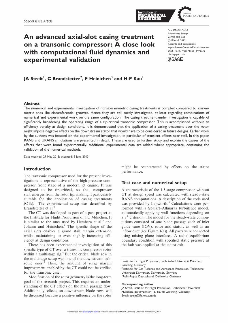
Figure 2 shows rotor loss loops on several individ-ual span positions. A significant increase in losseswhen approaching stall (rising relative inflow angle�1) points to a full utilization of the operatingrange. This is visible only for the span positionsclose to the casing. Thus the tip region seems toreach the stability limit before the lower sections.The small operating range in the relative inflowangle �1 is typical for a transonic rotor (see Bolcsand Suter8 p. 115ff). The lower sections do not experi-ence a broader range of relative inflow angles whichthey could probably handle since they are subjected tosubsonic inflow at their radial positions.
After locating the stall inception close to thecasing, the specific mechanism is of interest sincethis is decisive for selecting the type of CT. Figure 3shows the distribution of the axial velocity componentat 96% span, illustrating areas of stagnation and
Figure 1. Computational domains. (a) For steady-state simulations of whole 1.5 stages. (b) For unsteady simulations, scaled CT and
(c) For unsteady simulations, scaled CT plus stator.
IGV: inlet guide vane.
684 Proc IMechE Part A: J Power and Energy 227(6)
at Technical University of Munich University Library on November 4, 2016pia.sagepub.comDownloaded from
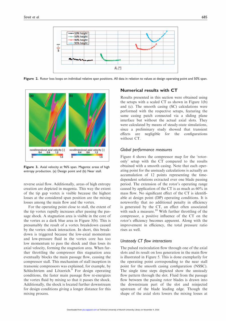
reverse axial flow. Additionally, areas of high entropycreation are depicted in magenta. This way the extentof the tip gap vortex is visible because the highestlosses at the considered span position are the mixinglosses among the main flow and the vortex.
For the operating point close to stall, the extent ofthe tip vortex rapidly increases after passing the pas-sage shock. A stagnation area is visible in the core ofthe vortex as a dark blue area in Figure 3(b). This ispresumably the result of a vortex breakdown causedby the vortex–shock interaction. In short, this break-down is triggered because the low-axial momentumand low-pressure fluid in the vortex core has toolow momentum to pass the shock and thus loses itsaxial velocity, forming the stagnation area. When fur-ther throttling the compressor this stagnation areaeventually blocks the main passage flow, causing thecompressor stall. This mechanism of stall inception intransonic compressors was explained, for example, bySchlechtriem and Lotzerich.9 For design operatingconditions, the faster main passage flow re-energizesthe vortex fluid by mixing so that it passes the shock.Additionally, the shock is located further downstreamfor design conditions giving a longer distance for thismixing process.
Numerical results with CT
Results presented in this section were obtained usingthe setups with a scaled CT as shown in Figure 1(b)and (c). The smooth casing (SC) calculations wereperformed with the respective setups, featuring thesame casing patch connected via a sliding planeinterface but without the actual axial slots. Theywere calculated by means of steady-state simulations,since a preliminary study showed that transienteffects are negligible for the configurationswithout CT.
Global performance measures
Figure 4 shows the compressor map for the ‘rotor-only’ setup with the CT compared to the resultsobtained with a smooth casing. Note that each oper-ating point for the unsteady calculations is actually anaccumulation of 12 points representing the time-dependent solutions extracted over one blade passingperiod. The extension of the rotor’s operating rangecaused by application of the CT is as much as 60% inmass flow. No significant effect of the CT is identifi-able at design point (DP) operating conditions. It isnoteworthy that no additional penalty in efficiencyis generated by the CT, an effect often associatedwith such a measure.10 With further throttling of thecompressor, a positive influence of the CT on therotor’s efficiency becomes apparent. Along with theimprovement in efficiency, the total pressure ratiorises as well.
Unsteady CT flow interactions
The pulsed recirculation flow through one of the axialslots and its result on loss generation in the main flowis illustrated in Figure 5. This is done exemplarily forthe operating point corresponding to the near stallpoint for the smooth casing configuration (NSSC).The single time steps depicted show the unsteadyflow pattern through the slot. Fluid from the passageflow between the passing rotor blades is drawn intothe downstream part of the slot and reinjectedupstream of the blade leading edge. Though theshape of the axial slots lowers the mixing losses at
Figure 2. Rotor loss loops on individual relative span positions. All data in relation to values at design operating point and 50% span.
Figure 3. Axial velocity at 96% span. Magenta: areas of high
entropy production. (a) Design point and (b) Near stall.
Streit et al. 685
at Technical University of Munich University Library on November 4, 2016pia.sagepub.comDownloaded from
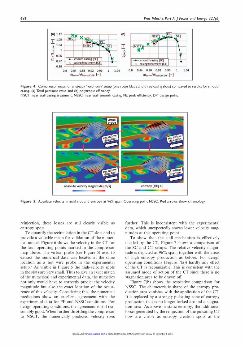
reinjection, these losses are still clearly visible asentropy spots.
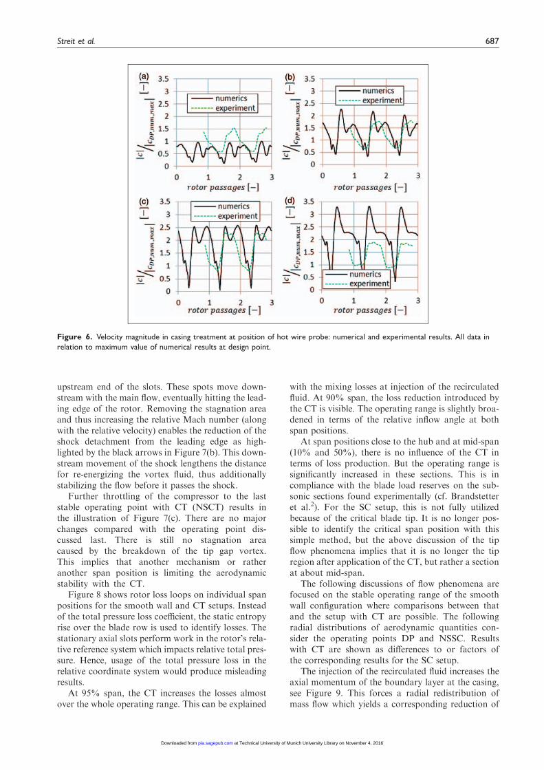
To quantify the recirculation in the CT slots and toprovide a valuable mean for validation of the numer-ical model, Figure 6 shows the velocity in the CT forthe four operating points marked in the compressormap above. The virtual probe (see Figure 5) used toextract the numerical data was located at the samelocation as a hot wire probe in the experimentalsetup.2 As visible in Figure 5 the high-velocity spotsin the slots are very small. Thus to give an exact matchof the numerical and experimental data, the numericsnot only would have to correctly predict the velocitymagnitude but also the exact location of the occur-rence of this velocity. Considering this, the numericalpredictions show an excellent agreement with theexperimental data for PE and NSSC conditions. Fordesign operating conditions, the agreement is still rea-sonably good. When further throttling the compressorto NSCT, the numerically predicted velocity rises
further. This is inconsistent with the experimentaldata, which unexpectedly shows lower velocity mag-nitudes at this operating point.
To show that the stall mechanism is effectivelytackled by the CT, Figure 7 shows a comparison ofthe SC and CT setups. The relative velocity magni-tude is depicted at 96% span, together with the areasof high entropy production as before. For designoperating conditions (Figure 7(a)) hardly any effectof the CT is recognizable. This is consistent with theassumed mode of action of the CT since there is nostagnation area to be drawn off.
Figure 7(b) shows the respective comparison forNSSC. The characteristic shape of the entropy pro-duction area vanishes with the application of the CT.It is replaced by a strongly pulsating zone of entropyproduction that is no longer forked around a stagna-tion area. As above in static entropy, the additionallosses generated by the reinjection of the pulsating CTflow are visible as entropy creation spots at the
Figure 5. Absolute velocity in axial slot and entropy at 96% span. Operating point NSSC. Red arrows show chronology.
Figure 4. Compressor maps for unsteady ‘rotor-only’ setup (one rotor blade and three casing slots) compared to results for smooth
casing. (a) Total pressure ratio and (b) polytropic efficiency.
NSCT: near stall casing treatment; NSSC: near stall smooth casing; PE: peak efficiency; DP: design point.
686 Proc IMechE Part A: J Power and Energy 227(6)
at Technical University of Munich University Library on November 4, 2016pia.sagepub.comDownloaded from
upstream end of the slots. These spots move down-stream with the main flow, eventually hitting the lead-ing edge of the rotor. Removing the stagnation areaand thus increasing the relative Mach number (alongwith the relative velocity) enables the reduction of theshock detachment from the leading edge as high-lighted by the black arrows in Figure 7(b). This down-stream movement of the shock lengthens the distancefor re-energizing the vortex fluid, thus additionallystabilizing the flow before it passes the shock.
Further throttling of the compressor to the laststable operating point with CT (NSCT) results inthe illustration of Figure 7(c). There are no majorchanges compared with the operating point dis-cussed last. There is still no stagnation areacaused by the breakdown of the tip gap vortex.This implies that another mechanism or ratheranother span position is limiting the aerodynamicstability with the CT.
Figure 8 shows rotor loss loops on individual spanpositions for the smooth wall and CT setups. Insteadof the total pressure loss coefficient, the static entropyrise over the blade row is used to identify losses. Thestationary axial slots perform work in the rotor’s rela-tive reference system which impacts relative total pres-sure. Hence, usage of the total pressure loss in therelative coordinate system would produce misleadingresults.
At 95% span, the CT increases the losses almostover the whole operating range. This can be explained
with the mixing losses at injection of the recirculatedfluid. At 90% span, the loss reduction introduced bythe CT is visible. The operating range is slightly broa-dened in terms of the relative inflow angle at bothspan positions.
At span positions close to the hub and at mid-span(10% and 50%), there is no influence of the CT interms of loss production. But the operating range issignificantly increased in these sections. This is incompliance with the blade load reserves on the sub-sonic sections found experimentally (cf. Brandstetteret al.2). For the SC setup, this is not fully utilizedbecause of the critical blade tip. It is no longer pos-sible to identify the critical span position with thissimple method, but the above discussion of the tipflow phenomena implies that it is no longer the tipregion after application of the CT, but rather a sectionat about mid-span.
The following discussions of flow phenomena arefocused on the stable operating range of the smoothwall configuration where comparisons between thatand the setup with CT are possible. The followingradial distributions of aerodynamic quantities con-sider the operating points DP and NSSC. Resultswith CT are shown as differences to or factors ofthe corresponding results for the SC setup.
The injection of the recirculated fluid increases theaxial momentum of the boundary layer at the casing,see Figure 9. This forces a radial redistribution ofmass flow which yields a corresponding reduction of
Figure 6. Velocity magnitude in casing treatment at position of hot wire probe: numerical and experimental results. All data in
relation to maximum value of numerical results at design point.
Streit et al. 687
at Technical University of Munich University Library on November 4, 2016pia.sagepub.comDownloaded from
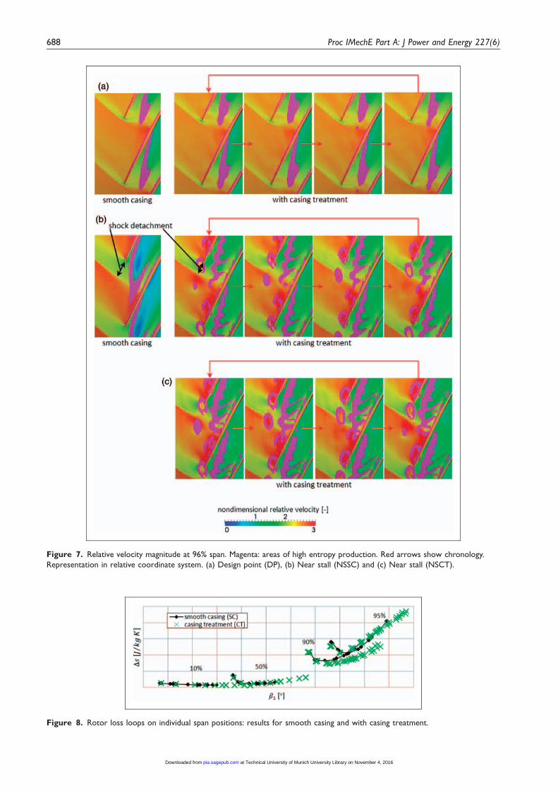
Figure 7. Relative velocity magnitude at 96% span. Magenta: areas of high entropy production. Red arrows show chronology.
Representation in relative coordinate system. (a) Design point (DP), (b) Near stall (NSSC) and (c) Near stall (NSCT).
Figure 8. Rotor loss loops on individual span positions: results for smooth casing and with casing treatment.
688 Proc IMechE Part A: J Power and Energy 227(6)
at Technical University of Munich University Library on November 4, 2016pia.sagepub.comDownloaded from
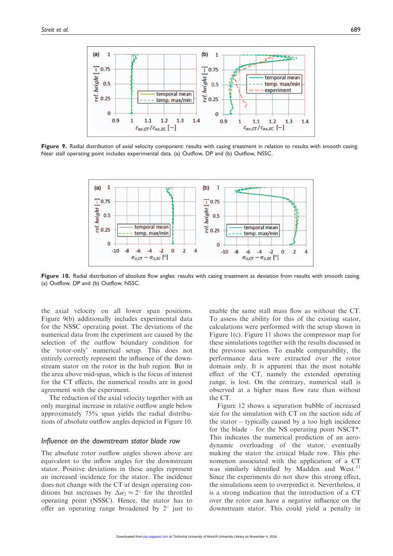
the axial velocity on all lower span positions.Figure 9(b) additionally includes experimental datafor the NSSC operating point. The deviations of thenumerical data from the experiment are caused by theselection of the outflow boundary condition forthe ‘rotor-only’ numerical setup. This does notentirely correctly represent the influence of the down-stream stator on the rotor in the hub region. But inthe area above mid-span, which is the focus of interestfor the CT effects, the numerical results are in goodagreement with the experiment.
The reduction of the axial velocity together with anonly marginal increase in relative outflow angle belowapproximately 75% span yields the radial distribu-tions of absolute outflow angles depicted in Figure 10.
Influence on the downstream stator blade row
The absolute rotor outflow angles shown above areequivalent to the inflow angles for the downstreamstator. Positive deviations in these angles representan increased incidence for the stator. The incidencedoes not change with the CT at design operating con-ditions but increases by ��2 � 2� for the throttledoperating point (NSSC). Hence, the stator has tooffer an operating range broadened by 2� just to
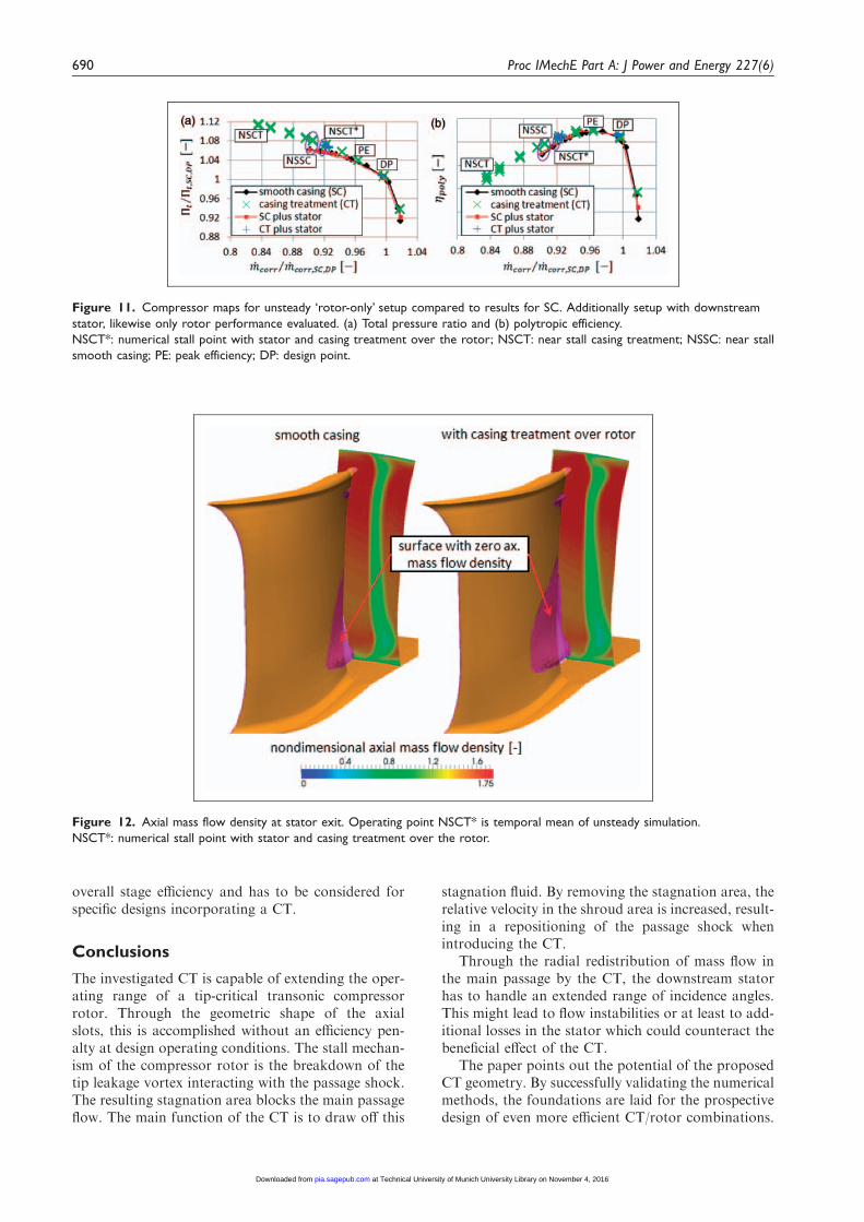
enable the same stall mass flow as without the CT.To assess the ability for this of the existing stator,calculations were performed with the setup shown inFigure 1(c). Figure 11 shows the compressor map forthese simulations together with the results discussed inthe previous section. To enable comparability, theperformance data were extracted over the rotordomain only. It is apparent that the most notableeffect of the CT, namely the extended operatingrange, is lost. On the contrary, numerical stall isobserved at a higher mass flow rate than withoutthe CT.
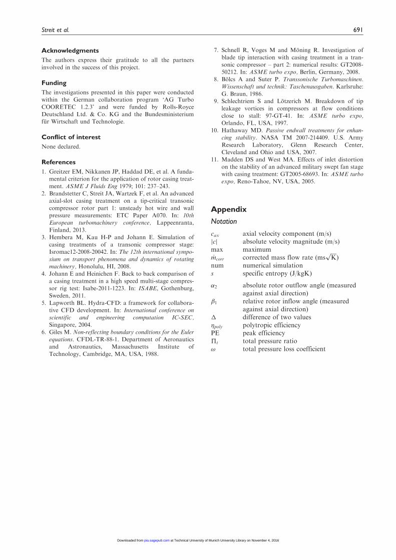
Figure 12 shows a separation bubble of increasedsize for the simulation with CT on the suction side ofthe stator – typically caused by a too high incidencefor the blade – for the NS operating point NSCT*.This indicates the numerical prediction of an aero-dynamic overloading of the stator, eventuallymaking the stator the critical blade row. This phe-nomenon associated with the application of a CTwas similarly identified by Madden and West.11
Since the experiments do not show this strong effect,the simulations seem to overpredict it. Nevertheless, itis a strong indication that the introduction of a CTover the rotor can have a negative influence on thedownstream stator. This could yield a penalty in
Figure 9. Radial distribution of axial velocity component: results with casing treatment in relation to results with smooth casing.
Near stall operating point includes experimental data. (a) Outflow, DP and (b) Outflow, NSSC.
Figure 10. Radial distribution of absolute flow angles: results with casing treatment as deviation from results with smooth casing.
(a) Outflow, DP and (b) Outflow, NSSC.
Streit et al. 689
at Technical University of Munich University Library on November 4, 2016pia.sagepub.comDownloaded from
overall stage efficiency and has to be considered forspecific designs incorporating a CT.
Conclusions
The investigated CT is capable of extending the oper-ating range of a tip-critical transonic compressorrotor. Through the geometric shape of the axialslots, this is accomplished without an efficiency pen-alty at design operating conditions. The stall mechan-ism of the compressor rotor is the breakdown of thetip leakage vortex interacting with the passage shock.The resulting stagnation area blocks the main passageflow. The main function of the CT is to draw off this
stagnation fluid. By removing the stagnation area, therelative velocity in the shroud area is increased, result-ing in a repositioning of the passage shock whenintroducing the CT.
Through the radial redistribution of mass flow inthe main passage by the CT, the downstream statorhas to handle an extended range of incidence angles.This might lead to flow instabilities or at least to add-itional losses in the stator which could counteract thebeneficial effect of the CT.
The paper points out the potential of the proposedCT geometry. By successfully validating the numericalmethods, the foundations are laid for the prospectivedesign of even more efficient CT/rotor combinations.
Figure 12. Axial mass flow density at stator exit. Operating point NSCT* is temporal mean of unsteady simulation.
NSCT*: numerical stall point with stator and casing treatment over the rotor.
Figure 11. Compressor maps for unsteady ‘rotor-only’ setup compared to results for SC. Additionally setup with downstream
stator, likewise only rotor performance evaluated. (a) Total pressure ratio and (b) polytropic efficiency.
NSCT*: numerical stall point with stator and casing treatment over the rotor; NSCT: near stall casing treatment; NSSC: near stall
smooth casing; PE: peak efficiency; DP: design point.
690 Proc IMechE Part A: J Power and Energy 227(6)
at Technical University of Munich University Library on November 4, 2016pia.sagepub.comDownloaded from
Acknowledgments
The authors express their gratitude to all the partners
involved in the success of this project.
Funding
The investigations presented in this paper were conductedwithin the German collaboration program ‘AG Turbo
COORETEC 1.2.3’ and were funded by Rolls-RoyceDeutschland Ltd. & Co. KG and the Bundesministeriumfur Wirtschaft und Technologie.
Conflict of interest
None declared.
References
1. Greitzer EM, Nikkanen JP, Haddad DE, et al. A funda-mental criterion for the application of rotor casing treat-
ment. ASME J Fluids Eng 1979; 101: 237–243.2. Brandstetter C, Streit JA, Wartzek F, et al. An advanced
axial-slot casing treatment on a tip-critical transonic
compressor rotor part 1: unsteady hot wire and wallpressure measurements: ETC Paper A070. In: 10thEuropean turbomachinery conference, Lappeenranta,
Finland, 2013.3. Hembera M, Kau H-P and Johann E. Simulation of
casing treatments of a transonic compressor stage:Isromac12-2008-20042. In: The 12th international sympo-
sium on transport phenomena and dynamics of rotatingmachinery, Honolulu, HI, 2008.
4. Johann E and Heinichen F. Back to back comparison of
a casing treatment in a high speed multi-stage compres-sor rig test: Isabe-2011-1223. In: ISABE, Gothenburg,Sweden, 2011.
5. Lapworth BL. Hydra-CFD: a framework for collabora-tive CFD development. In: International conference onscientific and engineering computation IC-SEC,Singapore, 2004.
6. Giles M. Non-reflecting boundary conditions for the Eulerequations. CFDL-TR-88-1. Department of Aeronauticsand Astronautics, Massachusetts Institute of
Technology, Cambridge, MA, USA, 1988.
7. Schnell R, Voges M and Moning R. Investigation ofblade tip interaction with casing treatment in a tran-sonic compressor – part 2: numerical results: GT2008-
50212. In: ASME turbo expo, Berlin, Germany, 2008.8. Bolcs A and Suter P. Transsonische Turbomaschinen.
Wissenschaft und technik: Taschenausgaben. Karlsruhe:
G. Braun, 1986.9. Schlechtriem S and Lotzerich M. Breakdown of tip
leakage vortices in compressors at flow conditions
close to stall: 97-GT-41. In: ASME turbo expo,Orlando, FL, USA, 1997.
10. Hathaway MD. Passive endwall treatments for enhan-cing stability. NASA TM 2007-214409. U.S. Army
Research Laboratory, Glenn Research Center,Cleveland and Ohio and USA, 2007.
11. Madden DS and West MA. Effects of inlet distortion
on the stability of an advanced military swept fan stagewith casing treatment: GT2005-68693. In: ASME turboexpo, Reno-Tahoe, NV, USA, 2005.
Appendix
Notation
cax axial velocity component (m/s)cj j absolute velocity magnitude (m/s)max maximum_mcorr corrected mass flow rate (ms
ffiffiffiffi
Kp
)num numerical simulations specific entropy (J/kgK)
�2 absolute rotor outflow angle (measuredagainst axial direction)
�1 relative rotor inflow angle (measuredagainst axial direction)
� difference of two values�poly polytropic efficiencyPE peak efficiency�t total pressure ratio! total pressure loss coefficient
Streit et al. 691
at Technical University of Munich University Library on November 4, 2016pia.sagepub.comDownloaded from