probability of failure of another ipl mitigate the ... · pdf file innovave entrepreneurial...
TRANSCRIPT

www.utm.my innova-ve●entrepreneurial●global 11

www.utm.my innova-ve●entrepreneurial●global 2
• Using redundant sensors and final redundant control elements
• Using multiple sensors with voting systems and redundant final control elements
• Testing the system components at specific intervals to reduce the PFD by detecting hidden failures
• Using deenergized trip system (i.e., a relayed shutdown system)

www.utm.my innova-ve●entrepreneurial●global 3
● Sufficiently independent so that the failure of one IPL does not adversely affect the probability of failure of another IPL
● Designed to prevent the hazardous event, or mitigate the consequences of the event
● Designed to perform its safety function during normal, abnormal, and design basis conditions
● Auditable for performance

www.utm.my innova-ve●entrepreneurial●global 4
PFD=0.1 PFD=0.1 PFD=0.01
Different Scenario Consequence Occurs
Unmitigated Risk
Initiating Event Frequency = 1/yr
Failure = 0.1
Failure = 0.1
Failure = 0.01
Success = 0.9
Success = 0.9
Success= 0.99
Frequency = 0.9/yr Safe Outcome Frequency = 0.09/yr Safe Outcome Frequency = 0.0099/yr Mitigated Release, tolerable outcome Frequency 0.0001/yr Consequences exceeding criteria
Mitigative Feature
Preventive Feature
Preventive Feature
Mitigated Risk = reduced frequency * reduced
consequence

www.utm.my innova-ve●entrepreneurial●global 5
PROCESS DESIGN
PREVENTION Mechanical Protection system Alarms with operator corrective actions Safety Instrumented Control System
CONTROL & MONITORING Basic Process Control System Monitoring system (Alarms) Operator Supervision
MITIGATION Mechanical Mitigation System Safety Instrumented Control System Safety Instrumented Mitigation System Operator Supervision
PLANT EMERGENCY RESPONSE Evacuation Procedure
COMMUNITY EMERGENCY RESPONSE Emergency Broadcasting
WHAT ARE IPL?
• Each layer is independent in terms of operation.
• The failure of one layer does not affect the next

www.utm.my innova-ve●entrepreneurial●global 6
Independent layer of protections (IPL) are features to provide risk reductions in plant operations.
Categories of IPLs: ● Prevention (active – lower probability)
– Alarm with operator response
– Safety Instrumented System
● Mitigation (active – lower probability/consequence) – Pressure relief valve
● Protection (passive – lower consequence) – Dikes
– Mechanical design
– Barricades

www.utm.my innova-ve●entrepreneurial●global 7
● LOPA is a semi-quantitative risk analysis technique that is applied following a qualitative hazard identification tool such as HAZOP.
● Similar to HAZOP LOPA uses a multi-discipline team ● LOPA can be easily applied after the HAZOP, but before fault
tree analysis ● LOPA focuses the risk reduction efforts toward the impact
events with the highest risks. ● It provides a rational basis to allocate risk reduction resources
efficiently. ● LOPA suggests the required Independent Layer of Protection
(IPL) required for the system to meet the required Safety Integrity Level (SIL)
7
www.utm.my innova-ve●entrepreneurial●global 8
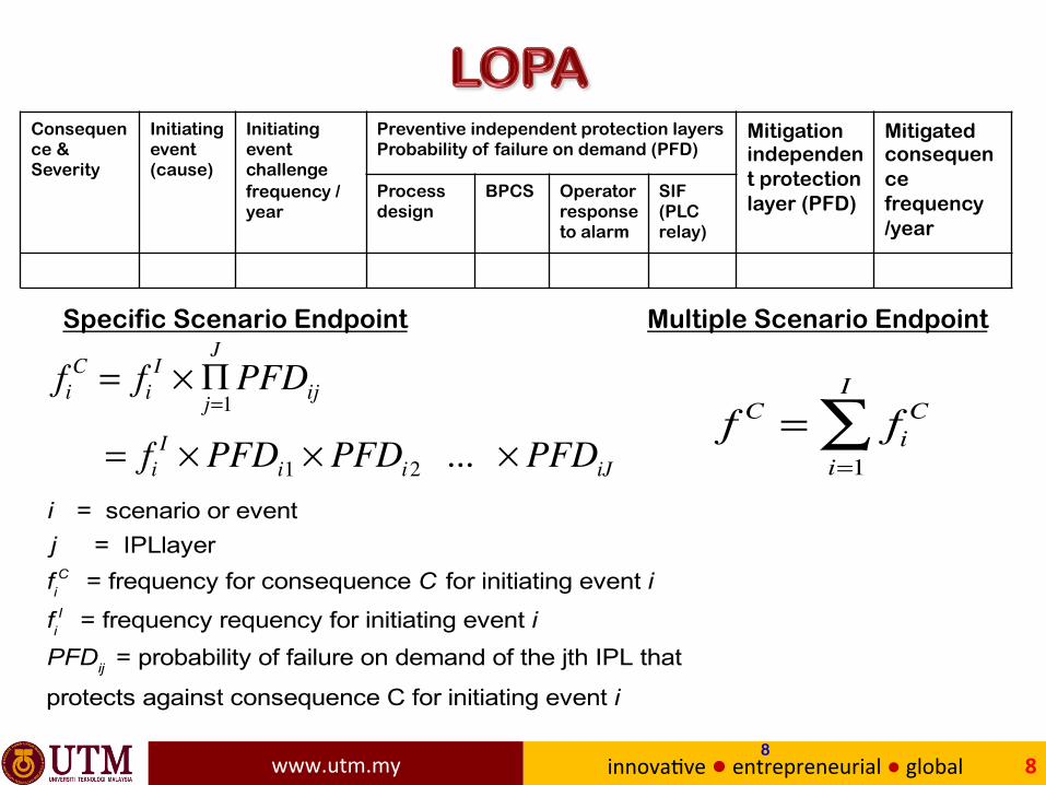
Consequence & Severity
Initiating event (cause)
Initiating event challenge frequency /year
Preventive independent protection layers Probability of failure on demand (PFD)
Mitigation independent protection layer (PFD)
Mitigated consequence frequency /year
Process design
BPCS Operator response to alarm
SIF (PLC relay)
fiC = fi
I × Πj=1
JPFDij
= fiI × PFDi1 × PFDi2 ... × PFDiJ
i = scenario or eventj = IPLlayer
fiC = frequency for consequence C for initiating event i
fiI = frequency requency for initiating event i
PFDij = probability of failure on demand of the jth IPL that
protects against consequence C for initiating event i
8
f C = fiC
i=1
I
∑
Specific Scenario Endpoint Multiple Scenario Endpoint

www.utm.my innova-ve●entrepreneurial●global 9
● There are five basic steps in LOPA: 1. Identify the scenarios
2. Select an accident scenario 3. Identify the initiating event of the scenario and
determine the initiating event frequency (events per year)
4. Identify the Independent Protection Layers (IPL) and estimate the probability of failure on demand of each IPL
5. Estimate the risk of scenario
9

www.utm.my innova-ve●entrepreneurial●global 10

www.utm.my innova-ve●entrepreneurial●global 11
Typical Frequencies of Initiating Events (f Ii) (From CCPS, 2001, Table 5.1) Initiating Event
Frequency
(events/year) Pressure vessel failure 10-5 to 10-7 Piping failure (full breach) 10-5 to 10-6 Piping failure (leak) 10-3 to 10-4 Atmospheric tank failure 10-3 to 10-5 Turbine/diesel engine overspeed (with casing breach) 10-3 to 10-4 Third party intervention (impact by backhoe, etc.) 10-2 to 10-4 Safety valve opens spuriously 10-2 to 10-4 Cooling water failure 1 to 10-2 Pump seal failure 10-1 to 10-2 BPCS loop failure 1 to 10-2 Pressure regulator failure 1 to 10-1 Small external fire 10-1 to 10-2 Large external fire 10-2 to 10-3 Operator failure (to execute routine procedure, assuming well trained, unstressed, not fatigued)
10-1 to 10-3 (units are
events/procedure)

www.utm.my innova-ve●entrepreneurial●global 12

www.utm.my innova-ve●entrepreneurial●global 13
Some surprising data for human reliability in process operations
PFD Situation Description
1.0 Rapid action based on complex analysis to prevent serious accident.
10-1 Busy control room with many distractions and other demands on time and attention
10-2 Quiet local control room with time to analyze
Source: Kletz (1999)

www.utm.my innova-ve●entrepreneurial●global 1414

www.utm.my innova-ve●entrepreneurial●global 15
low moderate high
Eve
nt
Sev
eri
ty extensive
serious
minor
Table entries word = qualitative risk description
number = required safety integrity level (SIL)
Safety Integrity Levels (Prob. Of failure on demand)
1 = .01 to .1
2 = .001 to .01
3 = .0001 to .001
Selection documented for legal requirements
Medium 2
Major 3
Major 3
Minimal 1
Medium 2
Major 3
Minimal 1
Minimal 1
Medium 2
Event Likelihood

www.utm.my innova-ve●entrepreneurial●global 16

www.utm.my innova-ve●entrepreneurial●global 17

www.utm.my innova-ve●entrepreneurial●global 18
• Proper materials of construction (reduce corrosion)
• Proper equipment specification (pumps, etc.)
• Good maintenance (monitor for corrosion, test safety systems periodically, train personnel on proper responses, etc.)
A typical value is PFD = 0.10
Often, credit is taken for good design and maintenance procedures.

www.utm.my innova-ve●entrepreneurial●global 19
The Layer of Protection Analysis (LOPA) is performed using a standard table for data entry.
Likelihood Probability of failure on demand
Mitigated likelihood = max
1)( iij
n
j
Ii
Ci fPFDff ≤⎥⎦
⎤⎢⎣⎡Π=
=
Consequence & Severity
Initiating event (cause)
Initiating event challenge frequency /year
Preventive independent protection layers Probability of failure on demand (PFD)
Mitigated event likelihood /year
Notes
Process design
BPCS
Operator response to alarm
SIF (PLC relay)
Additional mitigation (safety valves, dikes, etc)

www.utm.my innova-ve●entrepreneurial●global 20
Feed Methane Ethane (LK) Propane Butane Pentane
Vapor product
Liquid product
Process fluid
Steam
FC-1
F2 F3
T1 T2
T3
T5
TC-6 PC-1
LC-1
AC-1
L. Key
Split range PAH
LAL LAH
cascade
Flash drum for component separation for this proposed design.

www.utm.my innova-ve●entrepreneurial●global 21
The target mitigated likelihood = 10-5 event/year
The likelihood of the event = 10-1 events/year
Flash drum for component separation for this proposed design.
Consequence & Severity
Initiating event (cause)
Initiating event frequency /year
Preventive independent protection layers Probability of failure on demand (PFD)
Mitigated event likelihood /year
Notes
Process design
BPCS
Operator response to alarm
SIF (PLC relay)
Additional mitigation (safety valves, dikes, etc)
High Pressure
Connection (tap) for sensor P1 plugged
Pressure sensor does not measure drum pressure

www.utm.my innova-ve●entrepreneurial●global 22
Some observations about the design.
• The drum pressure controller uses only one sensor; when it fails, the pressure is not controlled.
• The same sensor is used for control and alarming. Therefore, the alarm provides no additional protection for this initiating cause.
• No safety valve is provided (which is a serious design flaw).
• No SIS is provided for the system. (No SIS would be provided for a typical design.)

www.utm.my innova-ve●entrepreneurial●global 23
Solution: Original design.
Feed Methane Ethane (LK) Propane Butane Pentane
Vapor product
Liquid product
Process fluid
Steam
FC-1
F2 F3
T1 T2
T3
T5
TC-6 PC-1
LC-1
AC-1 L. Key
Split range
LAL LAH
cascade
PAH
When the connection to the sensor is plugged, the controller and alarm will fail to function on demand

www.utm.my innova-ve●entrepreneurial●global 24
Solution using initial design and typical published values.
Much too high! We must make improvements to the design.
Gap = 10-2/10-5 = 103 (sometimes given as the exponent “3”)
Consequence & Severity
Initiating event (cause)
Initiating event frequency /year
Preventive independent protection layers Probability of failure on demand (PFD)
Mitigated event likelihood /year
Notes
Process design
BPCS Operator response to alarm
SIF (PLC relay)
Additional mitigation (safety valves, dikes, etc)
High Pressure
Connection (tap) for sensor P1 plugged
0.1 0.1 1.0 1.0 1.0 1.0 0.01 Pressure sensor does not measure drum pressure

www.utm.my innova-ve●entrepreneurial●global 25
Feed Methane Ethane (LK) Propane Butane Pentane
Vapor product
Liquid product
Process fluid
Steam
FC-1
F2 F3
T1 T2
T3
T5
TC-6 PC-1
LC-1
AC-1
L. Key
Split range
LAL LAH
cascade
P-2 PAHH
PAH

www.utm.my innova-ve●entrepreneurial●global 26
Enhanced design includes separate P sensor for alarm and a pressure relief valve.
The enhanced design achieves the target mitigated likelihood.
Verify table entries.
Consequence & Severity
Initiating event (cause)
Initiating event frequency /year
Preventive independent protection layers Probability of failure on demand (PFD)
Mitigated event likelihood /year
Notes
Process design
BPCS Operator response to alarm
SIF (PLC relay)
Additional mitigation (safety valves, dikes, etc)
High Pressure
Connection (tap) for sensor P1 plugged
0.1 0.1 1.0 0.1 1.0 PRV 0.01
0.00001 Pressure sensor does not measure drum pressure The PRV must exhaust to a knock- out and flare system

www.utm.my innova-ve●entrepreneurial●global 27
For the solution in the LOPA table and process sketch, describe some situations (equipment faults) in which the independent layers of protection are
- Independent
- Dependent
For each situation in which the IPLs are dependent, suggest a design improvement that would remove the common cause fault, so that the LOPA analysis in the table would be correct.
Hints: Consider faults such as sensor, power supply, signal transmission, computing, and actuation

www.utm.my innova-ve●entrepreneurial●global 28
• The most common are BPCS, Alarms and Pressure relief. They are typically provided in the base design.
• The next most common is SIS, which requires careful design and continuing maintenance
• The probability of failure on demand for an SIS depends on its design. Duplicated equipment (e.g., sensors, valves, transmission lines) can improve the performance
• A very reliable method is to design an “inherently safe” process, but these concepts should be applied in the base case

www.utm.my innova-ve●entrepreneurial●global 29
¡ The safety interlock system (SIS) must use independent sensor, calculation, and final element to be independent!
¡ We desire an SIS that functions when a fault has occurred and does not function when the fault has not occurred.
¡ SIS performance improves with the use of redundant elements; however, the systems become complex, requiring high capital cost and extensive ongoing maintenance.
¡ Use LOPA to determine the required PFD; then, design the SIS to achieve the required PFD.

www.utm.my innova-ve●entrepreneurial●global 3030