primary standards of airprimary standards of air kerma for 60co
TRANSCRIPT

PRIMARY STANDARDS of AIRPRIMARY STANDARDS of AIRPRIMARY STANDARDS of AIR KERMA for 60CO and X-RAYS
PRIMARY STANDARDS of AIR KERMA for 60CO and X-RAYS
& ABSORBED DOSE in PHOTON
& ABSORBED DOSE in PHOTONABSORBED DOSE in PHOTON
and ELECTRON BEAMSABSORBED DOSE in PHOTON
and ELECTRON BEAMSMalcolm McEwen

Definitions:
Standard – “instrument/measurement/artifact intended to define, realize, conserve or reproduce a
it tit t f ”unit or quantity to serve as a reference”
Primary standard – “standard that is designated or widely acknowledged as having the highestwidely acknowledged as having the highest metrological qualities and whose value is accepted without reference to other standards of same quantity”
N ti l t d d “ d d i d bNational standard – “standard recognized by a national decision to serve as the basis for assigning values to other standards of the quantity concerned” q y
Secondary standard – “standard whose value is assigned by comparison with a primary standard of the same quantity”same quantity

So that’s clear?
“I shall not attempt today to further define [it]……….but I s a o a e p oday o u e de e [ ] buknow it when I see it.”
Justice Potter Stewart, 1964
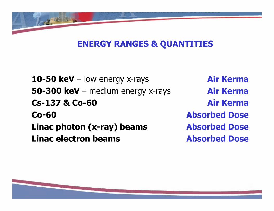
ENERGY RANGES & QUANTITIES
10-50 keV – low energy x-rays50-300 keV – medium energy x-rays
Air KermaAir Kerma50 300 keV medium energy x rays
Cs-137 & Co-60Co-60
Air KermaAir Kerma
Absorbed DoseLinac photon (x-ray) beams Linac electron beams
Absorbed DoseAbsorbed Dose

1. kV x-rays – air kerma1. kV x rays air kerma
The primary standard for 10-300 kV x-rays is the F Ai Ch bFree Air Chamber

kV x-rays – air kermakV x rays air kerma
The primary standard for 10-300 kV x-rays is the F Ai Ch bFree Air Chamber
g-11
eW
mQ
g-11
eW X = K
air
airair
W/e = 33.97 eV
mair ?

kV x-rays – air kermakV x rays air kerma
Vair = AL The air volume is air
defined mechanically

Corrections correctionsCorrections, corrections …..
1WQ ionpolhumescatt
airair
airair PPKKKK
g-11
eW
VQ = K
• Katt - attenuation of the primary X-ray beam between the aperture and collecting volume
• Ksc - the extra ionization collected from electrons produced by photons scattered within the chamber
• Ke - ionization lost when electrons strike the collecting electrode.

An aside on HumidityAn aside on Humidity
1.0035
We are all familiar with correcting readings for temperature and pressure (forget them here at your peril)
1.0025
1.0030
your peril)
Humidity, however, is generally ignored, but for kVKhum
1.0015
1.0020
Humidity, however, is generally ignored, but for kV primary standards it is an important correction
1.0005
1.0010
50 kVC 60
0 20 40 60 80 1000.9995
1.0000Co-60
Relative Humidity (%)
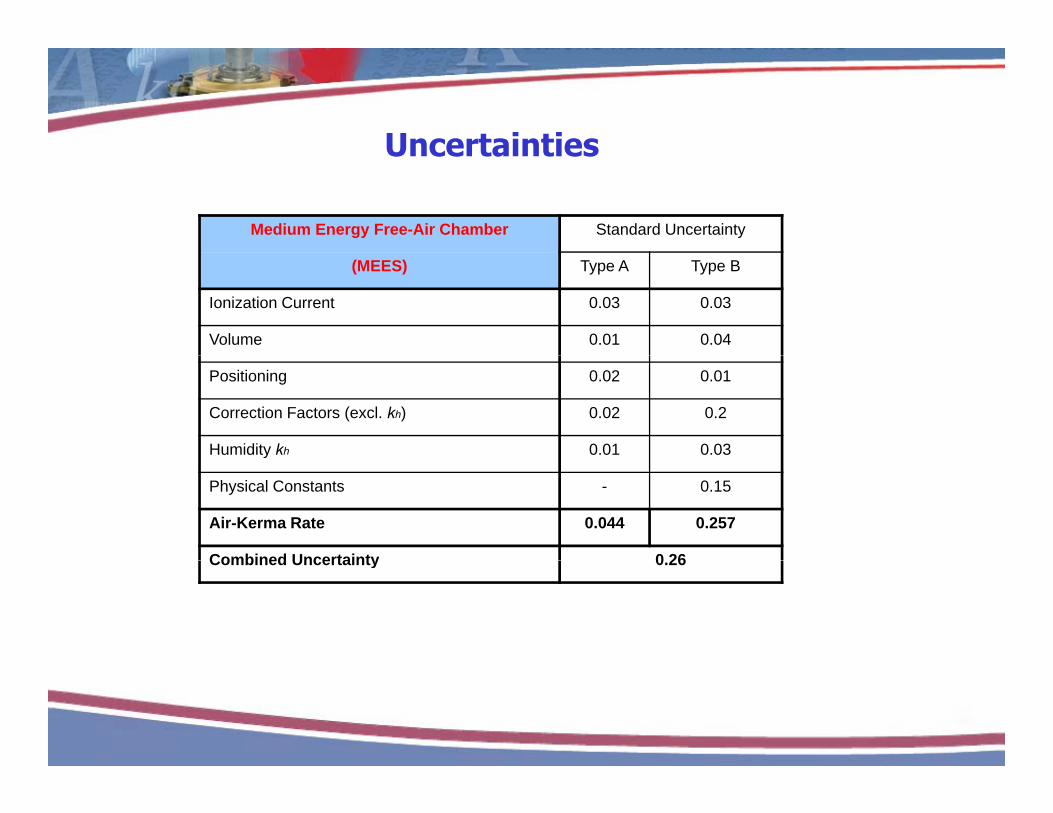
UncertaintiesUncertainties
Medium Energy Free-Air Chamber Standard Uncertainty
(MEES) Type A Type B
Ionization Current 0.03 0.03
Volume 0.01 0.04
Positioning 0.02 0.01
Correction Factors (excl. kh) 0.02 0.2
Humidity kh 0.01 0.03y
Physical Constants - 0.15
Air-Kerma Rate 0.044 0.257
Combined Uncertainty 0 26Combined Uncertainty 0.26

Alt ti d i f f i h bAlternative designs of free-air chamber1. Attix design
Designed by Attix in 1961
Extensible length of chamber• No guarding-electrode
system• No voltage dividerNo voltage divider• Eliminates stringent power
supply requirementsE lti f fi ld• Errors resulting from field-nonuniformity are eliminated

Atti h b ti i i lAttix chamber operating principle
Front and back move
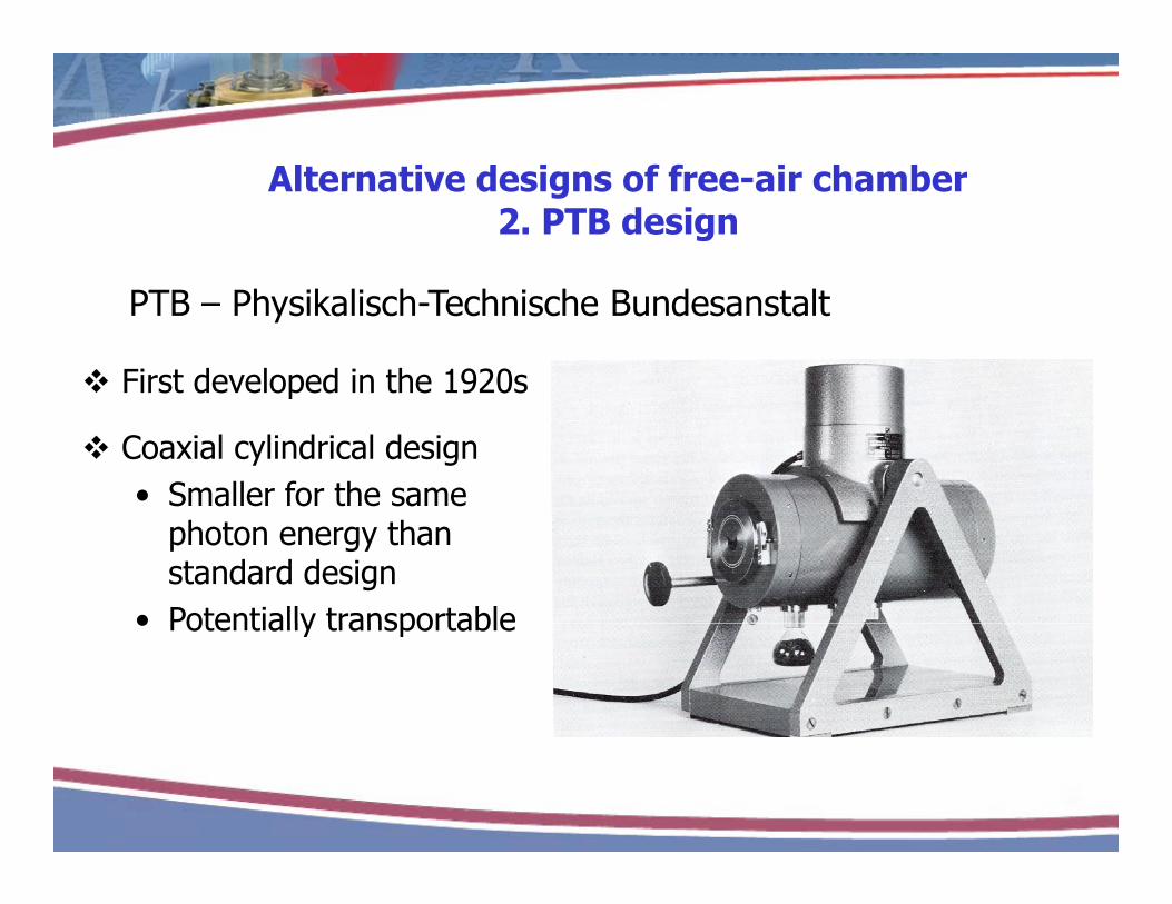
Alt ti d i f f i h bAlternative designs of free-air chamber2. PTB design
PTB – Physikalisch-Technische Bundesanstalt
First developed in the 1920sp
Coaxial cylindrical design • Smaller for the same
photon energy than standard design
• Potentially transportable• Potentially transportable
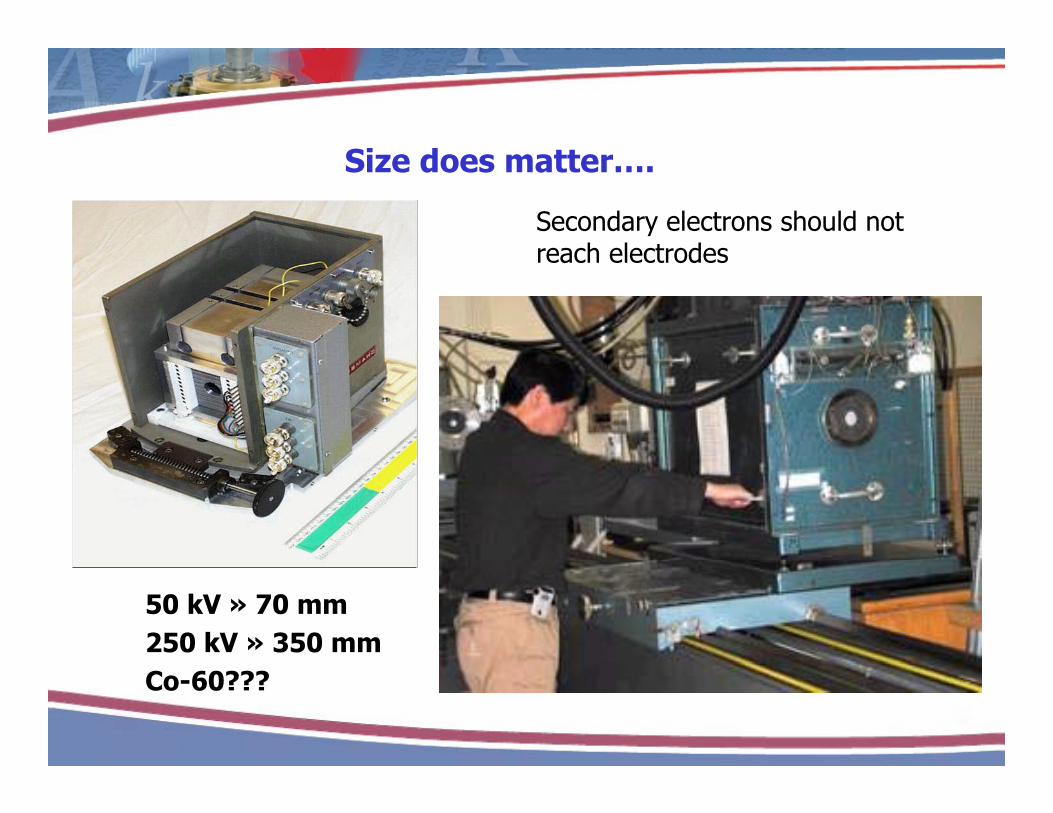
Si d ttSize does matter….
Secondary electrons should not reach electrodesreach electrodes
50 kV » 70 mm250 kV » 350 mmCo-60???

Si d ttSize does matter….
Secondary electrons should not reach electrodesreach electrodes
50 kV » 70 mm250 kV » 350 mmCo-60???
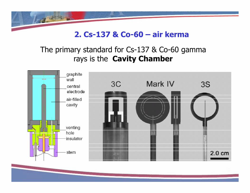
2. Cs-137 & Co-60 – air kerma2. Cs 137 & Co 60 air kerma
The primary standard for Cs-137 & Co-60 gamma rays is the Cavity Chamberrays is the Cavity Chamber
Cavity theory before 9 am is a cruel and unusual punishment
O i th h l lOverview - measure the charge, apply a large number of corrections and factors from tablesDetail - consult your textbook

What is required?What is required?
ilhtttenair
air PPKKKKKL1WQ=K
• A h b i h ll
ionpolhumstemanscattgairairgairair
air PPKKKKKg-1
eV
K
,,
• A chamber with a very well defined volume
• W/e & L• W/e & Lg/air
• Monte Carlo
• A lot of time
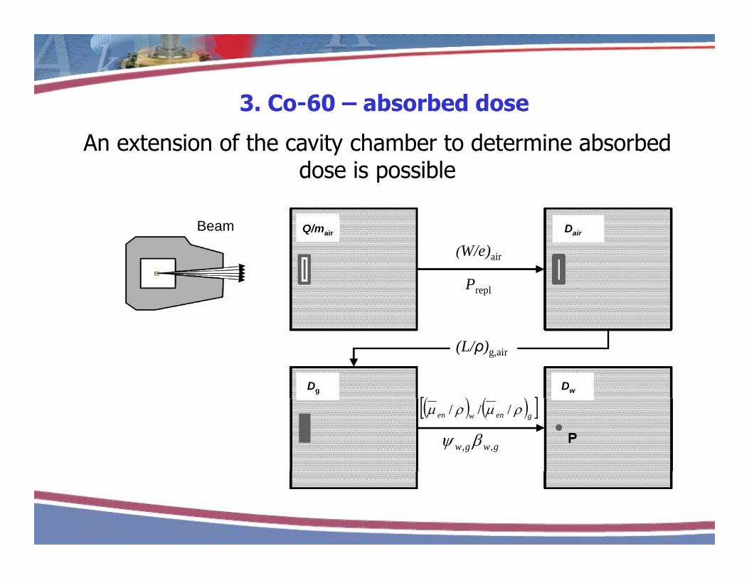
3. Co-60 – absorbed dose3. Co 60 absorbed dose
An extension of the cavity chamber to determine absorbed dose is possiblep
Beam Q/mair Dair
(W/e) i
Beam Q/mair Dair
(W/e) i
Prepl
(W/e)air
Prepl
(W/e)air
Dg Dw
(L/ρ)g,air
Dg Dw
(L/ρ)g,air
genwen ///
gwgw ,,
genwen ///
gwgw ,,

Uncertainties
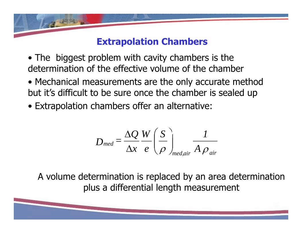
Extrapolation ChambersExtrapolation Chambers
• The biggest problem with cavity chambers is the determination of the effective volume of the chamber• Mechanical measurements are the only accurate method but it’s difficult to be sure once the chamber is sealed up• Extrapolation chambers offer an alternative:
1SWQ airairmed,
med A1 S
eW
xQ = D
A volume determination is replaced by an area determination plus a differential length measurementplus a differential length measurement

Extrapolation ChambersExtrapolation Chambers

But…But…
1SWQ=D
The A∆x determination turns out to be not that much
airairmed,med A
ex
=D
• The A∆x determination turns out to be not that much easier than a measurement of volume• The value of S/ρ isn’t very well known except for graphite/ρ y p g p• Long term stability is not likely to be as good as for a fixed-volume chamber (and standards labs love stability).
Extrapolation chambers are used, but t f t l bnot for external beams
4. Linac beams – absorbed dose4. Linac beams absorbed dose
• There is a very obvious change when we move y gto linac beams. • The standards no longer look all the same• Cavity chambers may have different geometries but they’re basically identical
The primary standard for absorbed dose in linac photon beams is the Calorimeterphoton beams is the Calorimeter

Aside – cavity theoryAside cavity theory
• Technically you can use cavity theory to derive absorbed d f hi h bdose for high-energy x-ray beams. • You need a very thick-walled chamber or a very large build-up cap.build up cap.
Tungsten-walled chambers have been builtBuild-up caps begin to look like phantoms
• However, you still don’t have the ‘unique’ situation of Co-60 of accurately knowing the values of W/e and Lg/air. • An MV cavity standard can therefore only be viewed as a• An MV cavity standard can therefore only be viewed as a secondary device.
Absorbed dose calorimetryAbsorbed dose calorimetry
Simple to define, a lifetime (well almost) to realize
Dm = cm ∆T
1. Measure a radiation-induced temperature rise.2 l h f h f h l2. Apply the specific heat capacity for the material
in question.
What’s the problem? It’s not cavity theory!
Wh i i b l t d i diffi lt?
i) Doses of interest are small
Why is measuring absolute dose is difficult?
i) Doses of interest are small ii) The quantity required is the dose in an
undisturbed phantom.iii) Th tit i d i th d t i t iiii) The quantity required is the dose at a point in
this phantom.iv) Scattered radiation contributes a significant
proportion of the absorbed dose v) Optimization of the measurement is difficultvi) Dose is material dependentvi) Dose is material dependent

Absorbed dose calorimeter the basic components
R2R2R2
Absorbed dose calorimeter – the basic components
Vout
R4
R3
2Rth+wire
Vout
R4
R3
2Rth+wire
Vout
R4
R3
2Rth+wire
3 0 10-6Vmthermistor
bridge circuit
3 0 10-63 0 10-6VmVmthermistor
bridge circuit
1.5 10-6
2.0 10-6
2.5 10-6
3.0 10
V out(V
)calorimeter phantom
bridge output signal
1.5 10-6
2.0 10-6
2.5 10-6
3.0 10
V out(V
)1.5 10-6
2.0 10-6
2.5 10-6
3.0 10
V out(V
)calorimeter phantom
bridge output signal
0.0 10-7
5.0 10-7
1.0 10-6
-200 -100 0 100 200
isolation0.0 10-7
5.0 10-7
1.0 10-6
-200 -100 0 100 2000.0 10-7
5.0 10-7
1.0 10-6
-200 -100 0 100 200
isolation
Time (s)Time (s)Time (s)
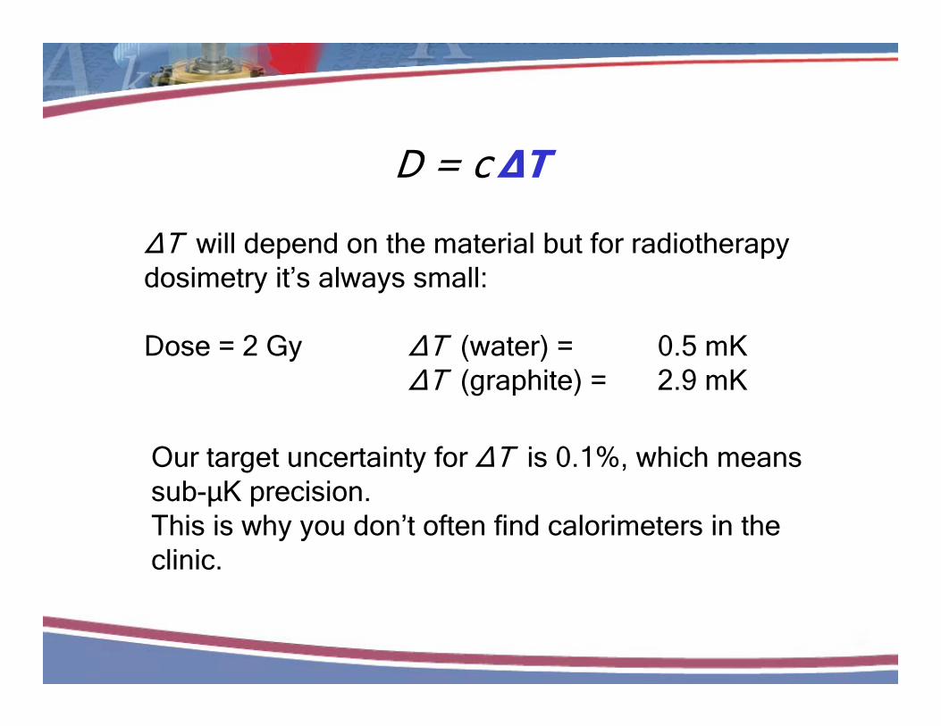
D = cΔT
ΔT will depend on the material but for radiotherapy dosimetry it’s always small:
Dose = 2 Gy ΔT (water) = 0.5 mKΔT (graphite) = 2.9 mK
Our target uncertainty for ΔT is 0.1%, which means sub-μK precision.sub μK precision.This is why you don’t often find calorimeters in the clinic.

D = cΔTWe’re measuring a temperature rise due to the energyWe re measuring a temperature rise due to the energy absorbed from the radiation beam. We therefore need a very stable background against
hi h thi t t iwhich we can measure this temperature rise.

D = cΔT
Two optionsPassive temperature control (thermal isolation)(thermal isolation)Active temperature control (feedback system)
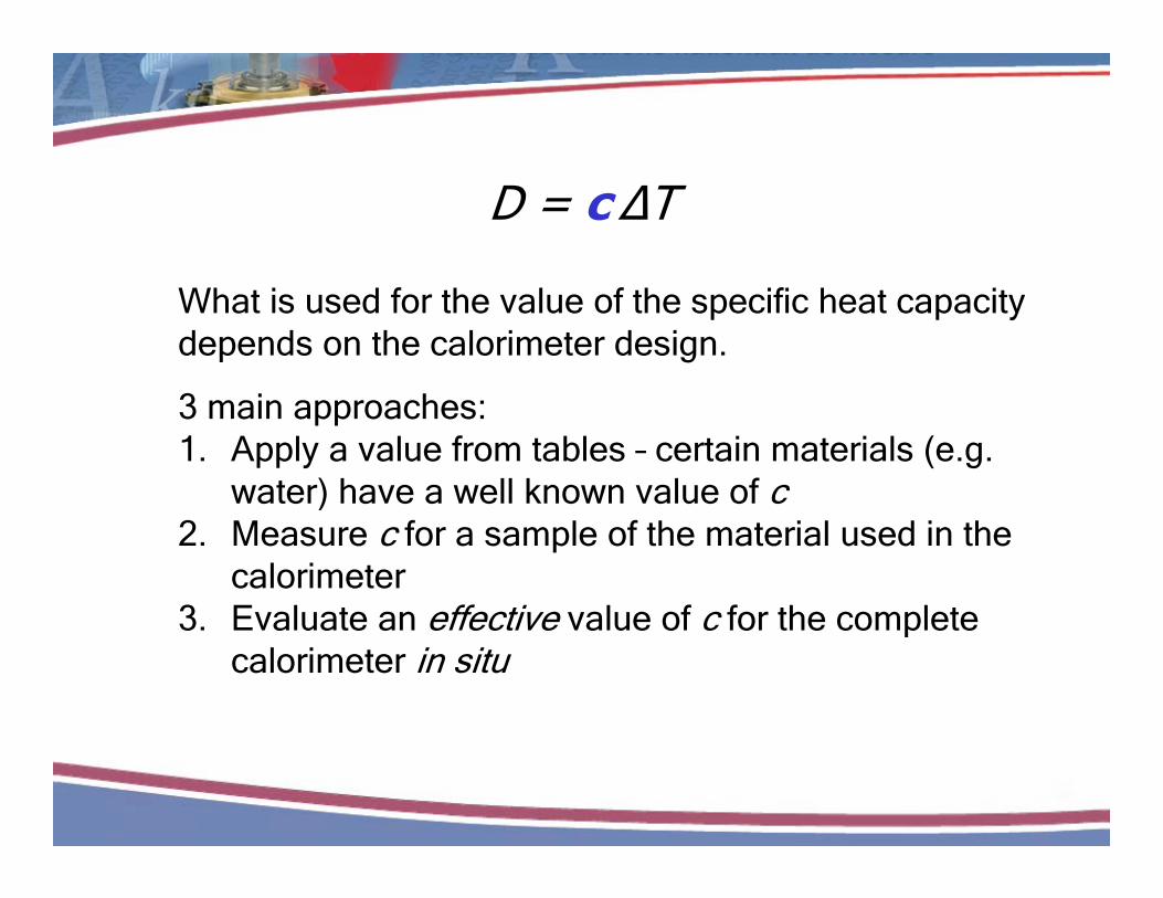
D = c ∆T
What is used for the value of the specific heat capacity depends on the calorimeter design.
3 main approaches:1. Apply a value from tables – certain materials (e.g.
water) have a well known value of c)2. Measure c for a sample of the material used in the
calorimeter3 Evaluate an effective value of c for the complete3. Evaluate an effective value of c for the complete
calorimeter in situ

Corrections correctionsCorrections, corrections …..
Things are never that simple:
Dm = cm ∆T Πki
Correction factors are very dependent on the specific calorimeter design (and there are lots) but may ca o ete des g (a d t e e a e ots) but ayinclude:
Perturbation correctionsPerturbation correctionsConversion from one material to anotherBeam uniformity correction (dose averaging)Radiochemistry

The Calorimeter GalleryThe Calorimeter Gallery
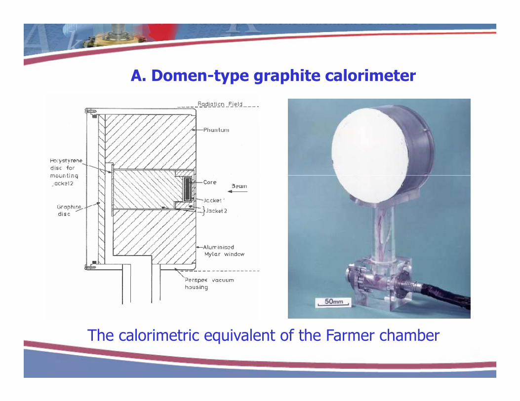
A Domen type graphite calorimeterA. Domen-type graphite calorimeter
The calorimetric equivalent of the Farmer chamber
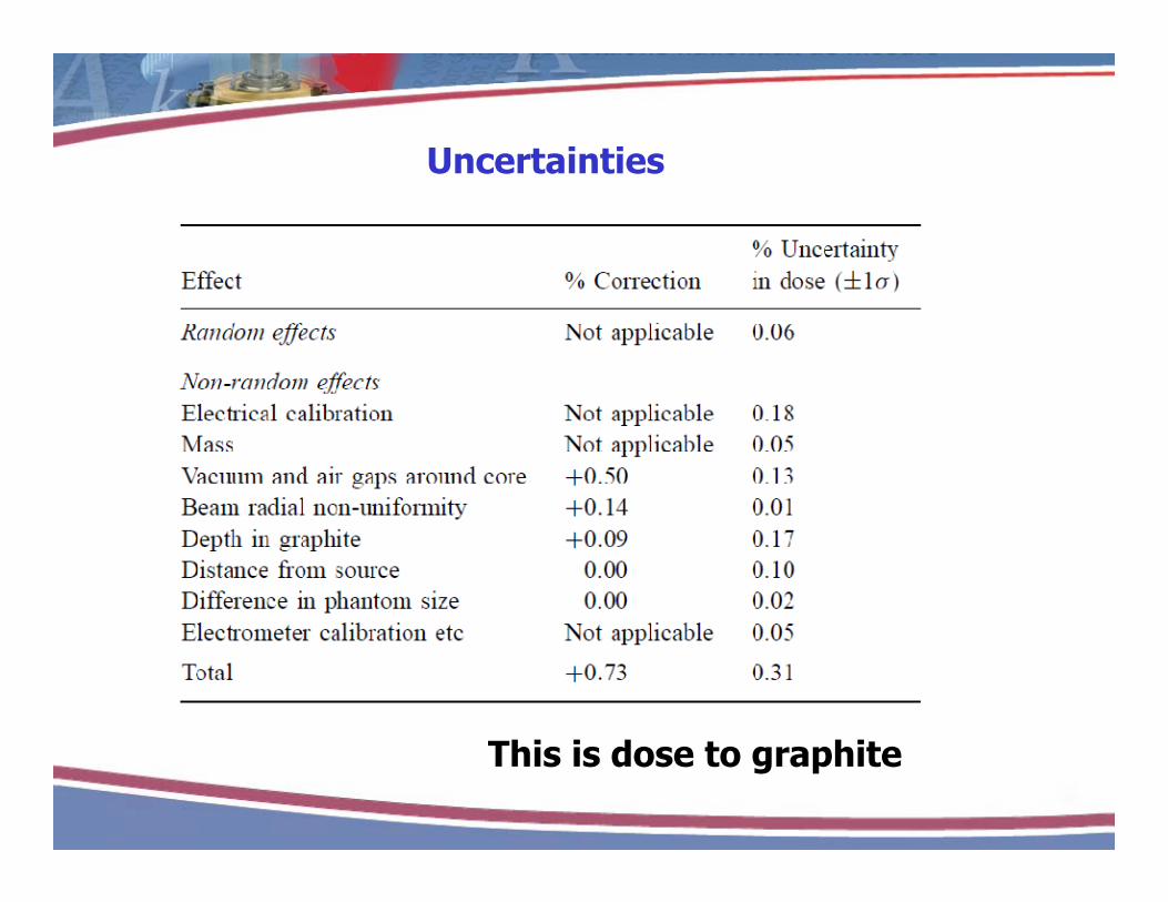
UncertaintiesUncertainties
This is dose to graphite

Dose conversionDose conversion
Utilises the photon-fluence scaling theorem
Requires knowledge of virtual source
i i dposition and corrections for:
ScatterAttenuationAttenuationPair production
Of M t C l if tOf, course, you can use Monte Carlo, if you must.
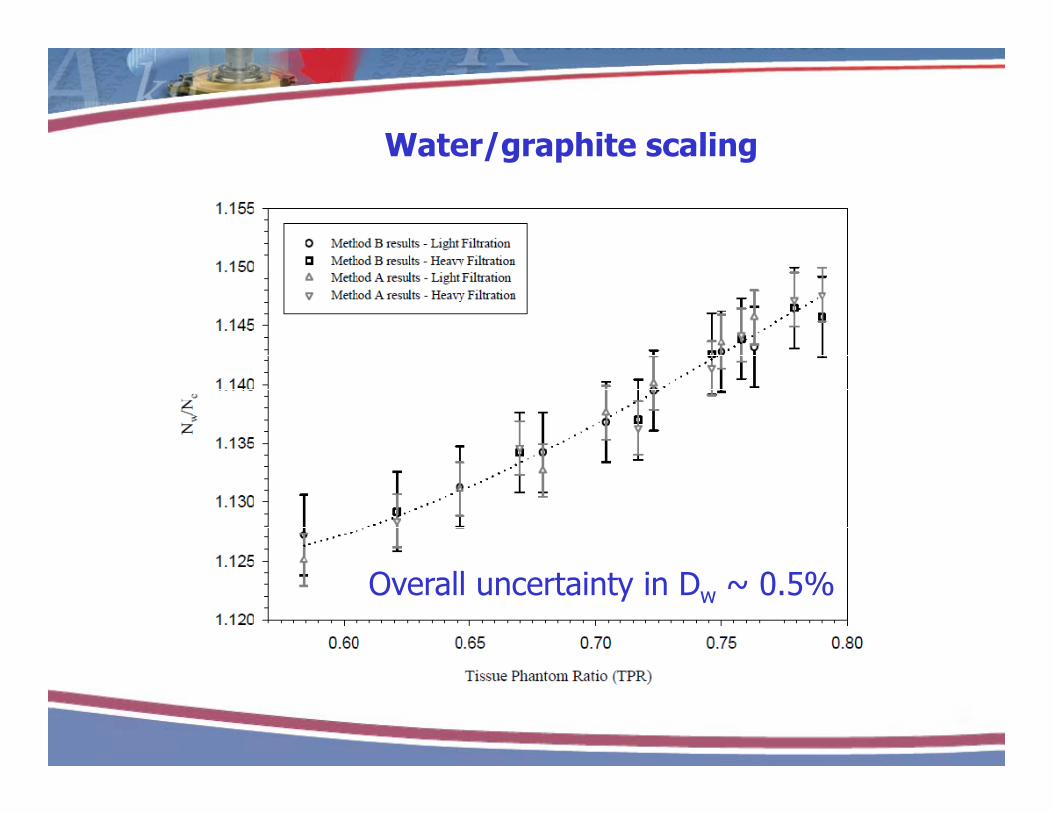
Water/graphite scalingWater/graphite scaling
Overall uncertainty in Dw ~ 0.5%
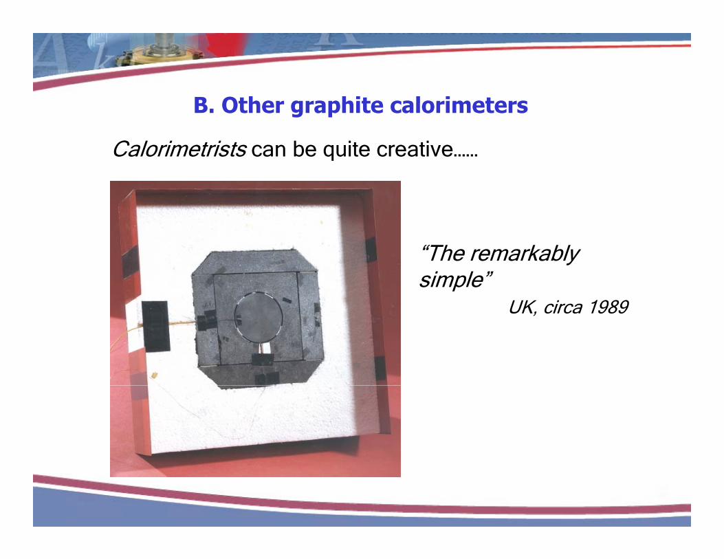
B Other graphite calorimetersB. Other graphite calorimeters
Calorimetrists can be quite creative……
“The remarkably simple”
UK, circa 1989,

“The impressivelyThe impressively complex”
France, 2007

“The carefully optimized”
BIPM, 2009

C. Water calorimeter development

Water calorimetry – the big problemsWater calorimetry the big problems
1. Convection 2 R di h i2. Radiochemistry3. Containment
Water calorimetry – the solutions
1. Operate at 4 °C 2. High purity water, known composition of dissolved
gases3 Careful design coupled with detailed thermal3. Careful design coupled with detailed thermal
modelling

D. The NRC water calorimeterCombines designs of Domen and Seuntjens
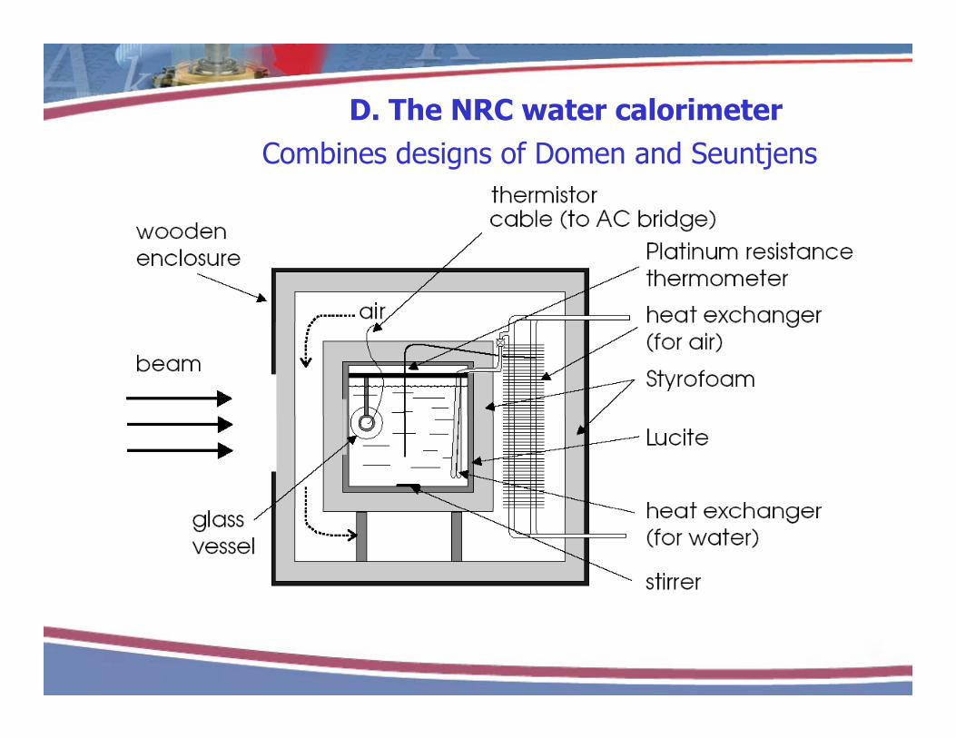
D. The NRC water calorimeterCombines designs of Domen and Seuntjens

D. The NRC water calorimeterCombines designs of Domen and Seuntjens

UncertaintiesUncertaintiesSource and type of uncertainty (in %) 60Co 10 MVType A
Reproducibility dT/MU 0.08 0.15Monitor reproducibility 0 02 0 12Monitor reproducibility 0.02 0.12
Type Bcw,p (specific heat capacity) < 0.005 < 0.005Thermistor sensitivity 0.08 0.08kc (heat loss) 0.10 0.10c ( )kp (vessel perturbation) 0.05 0.05kHD (heat defect) 0.15 0.15kdd (profile non-uniformity) 0.01 0.04Positioning calorimeter, probes and vessel 0.13 0.13g , p
Pdd 0.03 0.04Pion 0.07 0.08Ppol 0.01 0.04P 0 05 0 05PTP 0.05 0.05Humidity 0.06 0.06Positioning chamber 0.06 0.06
Overall ND,w 0.28 0.35
Not a single MC-derived factor

Size matters (II)Size matters (II)
The NRC water calorimeter is big and heavy:
85 cm cube, 50 kg, g
Moving it within the lab is bad enough
Can we make something smaller?

Size matters (II)Size matters (II)

What about electron beams?What about electron beams?
Standards for electron beam dosimetry have lagged y ggbehind photon standards:
1974 – NIST graphite calorimeter1990 NPL th l l hit l i t1990s – NPL therapy-level graphite calorimeter
1988 – first calibration service for linac photon beams1988 first calibration service for linac photon beams1998 – first service for electron beams
Very few institutions presently involved

Problem #1Electron range

Problem #2Net charge

Electron beam calorimetryElectron beam calorimetry
As for photon beams both graphite and water p g pcalorimeters are in use at primary laboratoriesWater calorimetry is particularly tricky due to
t b ti i f t i t l l d ithperturbation issues of containment vessel coupled with electron rangeBut… it has been done, and at a university!But… it has been done, and at a university!

McGill University Water CalorimeterMcGill University Water CalorimeterStewart, Seuntjens, et al
Pancake-type vessel and vertical beam geometry allow measurements down to 6 MeVmeasurements down to 6 MeV

5. Non-calorimetric standards for MV beams5. Non calorimetric standards for MV beams
What is often forgotten in the discussion of standards is that the radiation facilities available can be crucial to the development and use of the detectorsof the detectors.

METAS (the Swiss Primary Laboratory)METAS (the Swiss Primary Laboratory)
Scanditronix MM22 Microtron

METAS (the Swiss Primary Laboratory)METAS (the Swiss Primary Laboratory)
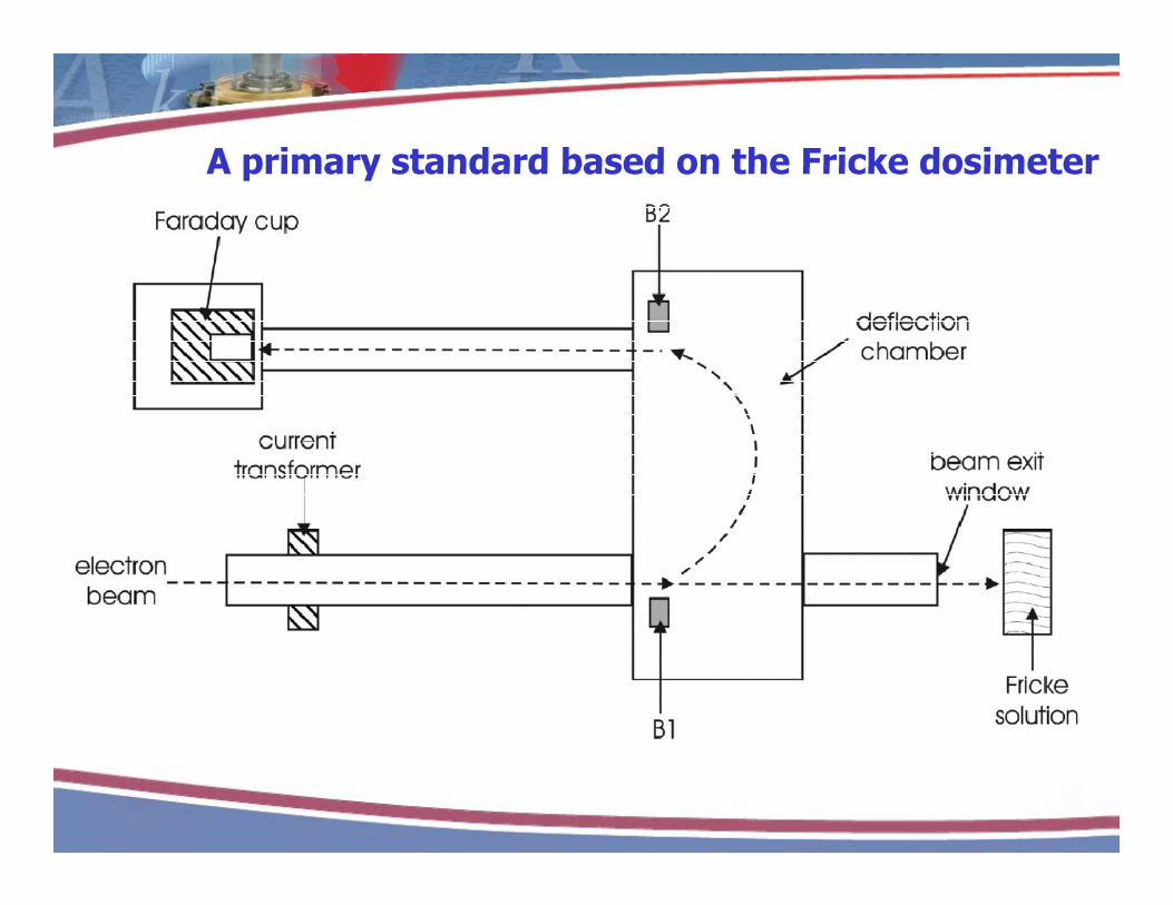
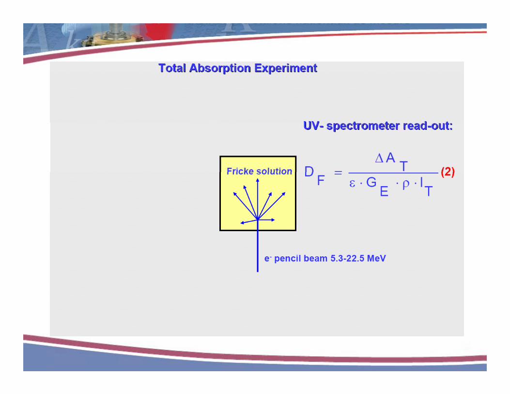
A primary standard based on the Fricke dosimeterA primary standard based on the Fricke dosimeter
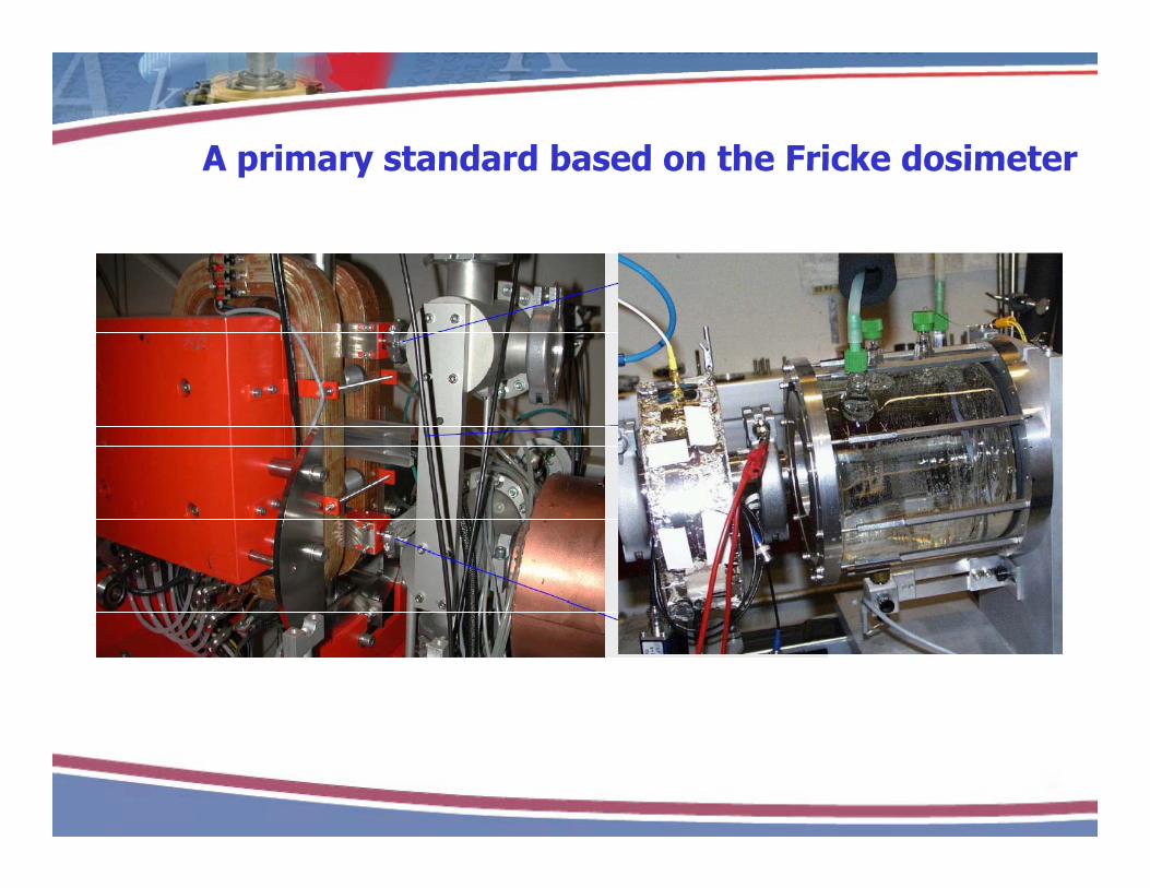
A primary standard based on the Fricke dosimeterA primary standard based on the Fricke dosimeter
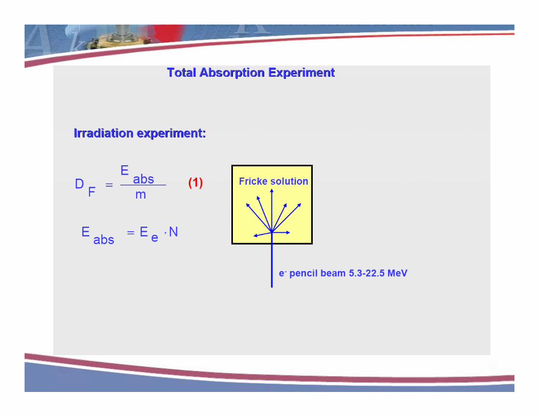


G-value determinationG value determination
1.015
sed 1.005
1.010
e3+),
norm
ali s
1.000
G(F
e
0.990
0.995
1999 2000 data
4 6 8 10 12 14 160.985
1999-2000 data2007 data
Es (MeV)


Comparison of standardsComparison of standards

1. kV x-rays – air kerma
1.008
1.010
1. kV x rays air kerma
e to
BIP
M
1.002
1.004
1.006
erm
a, re
lativ
e
0.998
1.000
Air
ke
0.992
0.994
0.996
tralia
ands
olan
d
UK
Italy
ngar
y
nada
ussi
a
man
y
Chi
na
ustri
a
USA
ance
0.990
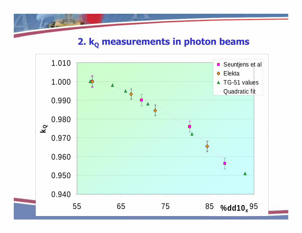
2. kQ measurements in photon beams2. kQ measurements in photon beams
1.010 Seuntjens et alElekta
0 990
1.000ElektaTG-51 valuesQuadratic fit
0.980
0.990
k Q
0.960
0.970
k
0.950
0.94055 65 75 85 95%dd10x

3. kQ measurements in electron beams3. kQ measurements in electron beams
1 08
1.10
TG-51 k'R50
TRS 398 k
pend
ence
1.06
1.08 TRS-398 kQ,Qint
NPL graphite calorimeterMETAS FrickeMcGill water calorimeterNRC water calorimeter
e en
ergy
dep
1.04
Rel
ativ
e
1.00
1.02
0 2 4 6 8 10 120.98
R50 (cm)
AcknowledgementsAcknowledgementsc o edge e tsc o edge e tsGerhard Stucki – METAS
Kristin Stewart Jan Seuntjens McGill UniversityKristin Stewart, Jan Seuntjens – McGill University
David Burns – BIPM
Carl Ross, John McCaffrey, Hong Shen – NRCCarl Ross, John McCaffrey, Hong Shen NRC
Simon Duane, Alan DuSautoy, Hugo Palmans – NPL
Josian Daures – LNHB