previous home next - e-library wcl home next ... accident during dreaming operations in coal...
TRANSCRIPT

Previous Home Next CONTENT D.G.M.S. CIRCULARS FOR 2002
1) Design of Draw bar of five tones capacity………………………………………. 2
2) Recommended CO(JQ of Practice for Operation and Maintenance of Flexible Trailing Cables Associated with Mobile Machines……………………………… 9
3) Facilities required at Group Training Centers and standard of training…………..11
4) Design of Lashing Chain…………………………………………………………. 15
5) Anchorage testing of installed roof bolts…………………………………………. 17
6) Accident during dreaming operations in coal mines……………………………… 20
7) Support of roof and side in belowground coalmines……………………………… 22
8) Use of Protective foot wears by female workers………………………………….. 27
9) Calibration environmental monitoring equipment………………………………… 28
10) Sale use of mobile Cranes Code or practice……………………………………….. 30
11) Providing Hash back arrears in gas welding/cutting………………………………. 36
12) Safety Management System - A guideline for Implementation…………………… 37
13) APPENDIX- I………………………………………………………………………38
Govt of India
Ministry of Labour
DGMS/( Tech)Circular No Dt. 28/01/2002 To
Owner, Agents & Managers of all Mines
Sub.: Design of Draw bar of five tones capacity
Enquiries into incidents or runaway of tubs due to breakage of draw bar or its end attachments have revealed that failure generally occurs due to one or more of the following reasons. (i) Manufacturing defects.
(ii) Material was not as per specification. (iii) Draw bar & attachment were deviated from the standard design. (iv) Draw bar & attachment were worn out beyond limit or damaged.
As per Regulation 89 (1) (c) of Coal Mines Regulation, 1957 and Regulation 97(l)(c) or Metalliferrous Mines Regulation. 1961 the attachment between a rope or locomotive and a tub and the attachment between any two tubs in a set or train of tubs is required to be a type approved by the Chief Inspector. In supersession of DGMS (tech) Circular 8 or l987, the type approval is as follows:
1.0 Design: Two designs tub draw bar and suitable end fittings are given in the sketch annexed. Any other design may be used with the express permission in writing by the Director General of Mines Safety; In the past, if any other design has been specially, permitted by the Director General of Mines Safety the same should be resubmitted for re-examining the matter. Existing drawbars not conforming to the designs shown in the Annexure should be replaced as early as possible, but not Inter than a period of one year from the date of this circular.
2.0 Material: (a) For Draw Bar: The material shall be any of the following;-
(i) 11Mn2 conforming to IS 4432-1967. (ii) 20Mn2 conforming to IS 1570-1961.
(b) For End Fittings: The material shall be any of the following;-
(i) 11Mn2 conforming to IS 4432-1967. (ii) 20Mn2 conforming to IS 1570-1961.

(iii) 20 Ni SSCr 50 Mo 20 conforming to IS 4432-1967.
(c) Only tested and certified material shall be used and some random samples shall be periodically tested to ensure proper quality of material.
3-0 Manufacturing & Workmanship: The draw bar shall be manufactured in workshops
having adequate facilities for forging, machining and heat treatment. The manufacturer shall give evidence of good workmanship and the draw bar shall be free from any visual defect. Holes in draw bar or its attachment shall be made by drilling and not by punching. Forged draw bar should avoid sudden change of section, thickness, and or shape or both. In draw bar with eye termination, the eye shape shall be made with the help of suitable mandrel and shall be so made that the line of pull is in line with the axis of the draw bar .The ends of draw bar shall be such that there is no fouling when tubs are buffed together and there is no locking on curves.
In draw bar of lapped, design, the lapped portion shall be riveted and side welded on both sides. -Alter riveting; the gap between lapped flat faces should not exceed 0.25mm. After riveting, each rivet shall be checked by light hammering and in case or any vibration due to slackness; the rivet shall be cut and redone.
In flat type draw bars, the ends shall be reinforced by welding a short piece plate of 12mm thickness & of size 85mm X 65mm. Flat type Draw bar shall be used with Tub coupling of serial No. 2 only as mentioned in Technical Circular I of 1986.
End fittings shall be manufactured by forging; machining and holes shall be drilled, not punched forging shall be such that the fibres of materials are not transverse to the line of pull.
4. Heat Treatment:
(a) After manufacture, draw bar & end fittings shall be normalised or normalised and
tempered, or hardened and tempered in an approved establishment at the following temperatures;
SL No
Designation of steel
Normalising Temp 0C
Hardening Temp 0C
Tempering Temp 0C
Quenching Agent
1. 11Mn2 870-910 870-910 550-660 Water or oil. 2. 20 Mn2 860-900 860-900 550-660 Water or oil 3. 20 Ni, 55C.
50 M0 20 820-850 Water
* Suitable temperature may be adopted so as to attain the optimum properties.
( b) Certificate of heat treatment from the approved establishment shall be-obtained.
5. Factor of Safety: The complete draw bar with end fittings shall have a factor of safety of
seven (7) with respect to S.W.L.

6. Hardness: Hardness for various materials shall be as follows:
(i) 11 Mn2 :190 to 220 HV (ii) 20 Mn2 : 200 to 230 HV (iii) 20Ni 55Cr 50Mo 20 : 250 10 280 HV
7. Identification: Each draw bar and end fitting shall be legibly marked on non-vital portion
with the following:
(i) Manufacturer's name & identification mark. (ii) Year of manufacture. (iii) Material (Symbol (M for 11 Mn2 /20 Mn2, Symbol A for 20 Ni55 Cr 50 Mo
20) (iv) Type of heat treatment - (N-Normalised, NT-Normalised & tempered, HT-
Hardened & tempered)
The stamp used for marking shall be of 5mm size. Care shall be taken that the indentation is neither too sharp nor excessive in depth.
8. Tests & Examination: After manufacture &heat treatment. At least 10% of the
manufactured/supplied lot of draw bar & its components shall be tested for proof load . i.e. for three limos the S.W.L.
It shall be further tested magnetically for cracks or any other defect. At least 1% of draw bar with end fitting of manufactured/supplied lot or minimum one number shall be subjected, to destructive testing.
A certificate! By a competent person making such test and inspection shall be furnished by the Manufacturer.
9. Record- A record of each draw bar stating its identification number, date of use with the
reference of the tub to which it is fitted should be maintained in a bound paged book. 10. Repair & discard: Wear & tear of any component shall not be built up by, welding.
Draw bar shall be discarded if it is found to have worn out to the extent so, as to reduce the factor of safety to six or if found to have some defect affecting its strength.
In addition, if there; is any derailment of tub, then draw bar and its attachment shall be carefully checked for. Damage before any tub is put back into service. Drawbars having permanent deformation/damage, shall be replaced.
End fittings shall be discarded when the maximum loss of cross-section due to wear over the. original cross-section exceeds 15% or exceeds. 12% with corrosion.

11. Life: Normal life of drawbar shall be three years.
Director General of Mines Safety.


Bharat Sarkar/Government of lndia Shram Mantialaya/Ministry of Labour
Khan Suraksha Mahanideshalaya
No. DGMS(Tech) Circular No, 2 Dt. 03/05/2002. To
The Owner, Agent and Manager of all the Cool Mines,
Subject.: Recommended CO(JQ of Practice for Operation and Maintenance of Flexible
Trailing Cables Associated with Mobile Machines. The present practice of manual handling of flexible trailing cables is fraught with danger. In view of this it is .suggested that where the machines arc required to move manual handling of cables should be avoided/minimized as far as practicable where circumstances permit by the use of properly designed, installed and maintained cable reeling or handling devices. As the above procedure calls for modification in the design of the machine and will take some time to materialize, the following measures should be adopted to ensure safety in use o( flexible trailing cables with electrically operated loading machines.
(i) Where flexible cables are not required to move, they should be effectively supported and protected against physical damage,
(ii) Where they are required to move, concerted and focused effort should be made to
train machine operators and cable men in safe operation of electrically operated loading machines and handling of the associated flexible trailing cables,
(iii) Cablemen/cable handlers/SDL operators are required to handle electrically live
flexible cables. Handling such live cables should be considered a specialized job and as such they should be considered under the category of competent person and hence should be properly trained and authorized in conformity with the provisions of the Rule 3 & 36(2) of the Indian Electricity Rules, 1956.
(iv) Such cable handlers should be provided with suitable personal protective
equipment such as hand gloves and other suitable appliances as deemed fit and their use should be ensured to ensure safety of such workmen.
As regards repair of the trailing cables the following measures are considered to be in order.
(i) Provision should be made in the colliery workshop with requisite equipment/ appliances for the efficient maintenance and repair of the trailing cables.
The floor space should be sufficient to permit the cable to be laid out for detailed examination, test and repair and to accommodate the necessary, benches and appliances.
(ii) Puncture in the outer sheath may be located readily by means of ordinary s park testing appliances or other instruments.
Special spark testing appliances/Instrurnents/Meggar Insulation Tester that are available should be used for detecting and locating fault between conductors. If the bulk of the cable is waterlogged it should be dried out, say by means of a vacuum impregnator such as is used for drying armature or by other means before any repairs are attempted. One method of drying out local moisture is by gently warming the cable on each side of the damage. High temperature must be avoided. Another method which is claimed to be very effective is to direct a strong stream of hot air from all electric hair dryer or any other 11 similar apparatus in. to, the joint and cable near it for about 20 minutes. While carrying out vulcanisation, due importance is to be given to the insulation resistance value of the cable at every step/stage of vulcanisation process.
(iii) Where two or more of the core conductors in a cable arc joined, it is essential, in
order to preserve flexibility that the joints shall be widely spaced.
(iv) It must be recognized that there is a limit to the extent to which a particular length of a cable may be repaired and that a stage is reached at which the cable should be scraped and a new one put in service.
The above notes are guidelines for repair and maintenance of flexible cables and is not exhaustive. Relevant Indian standard, manufacturer's instruction and guidelines and the expertise of the skilled workmen should also be taken into consideration for maintenance and repair of flexible cables for mobile machines in mines.
Director-General of Mines Safety.

BHARAT SARKAR/ GOVERNMENT OF INDIA SHRAM MANTRALAYA/ MI-NISTRY OF LABOUR
KHAN SURAKGHA MAHANIDESHALAYA
DGMS (Tech) Circular - No. 3 Dt. 10/05/2002 To
The Owners, Agents and Managers of all Coal and Metalliferous Mines.
Sub.: Facilities required at Group Training Centers and standard of training.
Ref.: Rule 6, 7, 8, 9, 10 & 11 of The Mines Vocational Training Rules, 1966.
As you arc aware that safely as well as productivity of any establishment is directly dependant on quality of training imparted to the workmen engaged on various jobs, it would be in the interest of both industry and the workmen if die best possible training imparted to our workmen for all-round growth of the industry and the nation. However, during recent inspections of Group Training Centers across the country owned by various public/private operators following deficiencies shortcomings were observed in spite of various Circulars issued time to time:
1. Provision: Almost all major operators have switched over from Mine Vocational Training center to Group/Vestibule Training Centers.
2. Accommodation: Adequate required accommodation had not been provided to
about 20% of the Group/Vestibule Training Centers (GTCs). Even in cases where suitable accommodation have been provided these were not maintained property.
3. Staffing: Adequate & duty qualified training staff were not provided at most of
the GTCs. In one or two cases even physically handicapped persons were employed who could not deliver lectures. Assistant Training Officer and Instructor(s) for Electrical & Mechanical subjects were not appointed at most of the GTCs,
4. Training Galleries: Training Gallery, which is probably the most important; aspect
of the training, was not provided at most of the GTCs In some eases, where these were provided, the same were neither properly equipped nor were being used for training.
5. Training Shop: Training Shop, for an effective and fruitful training to
mechanical and electrical work-persons, was not provided at most of GTCs.
6. Training Aids: Even though, OHPs, Film or Slide Projectors were provided at most of the G.T.Cs, except for one or two cases, other required input material like transparencies, slides and or films were not provided One of the most important tool for communication in to-days world i.e. computer with proper software were not provided except for one or two GTCs in private sector.

7. Course Material: Except for one or two GTCs others were not. preparing the
required course material either, for the trainees or for the instructors. Most of the GTCs even did not have a library with required books and the facility to generate course material of their own.
8. Attitude or Training Staff: In most of (he cases training start including training
officer did not have positive attitude and in some cases they felt frustrated as if they were punished by having-been posted at the training center At most of the GTCs due importance was not given to hands on or oh the job training. Attitude of Training: Due to unimaginative & un-impressive training methods adopted by the training staff, and. in some case inconvenient training schedule (before of after duty hours) most of (he trainees, specially those coming for refresher courses, indicated dull response to the (raining programmes and even had tendency to evade training session(s).
9. Managements Response: Except for few cases, both local as well w higher,
management indicated poor response to the training needs/requirement. In most of (it cases an impression was conveyed as if expenditure on training was wastage of money other resources.
To improve performance, of GTCs and to ensure effective and. Gainful training lo the workmen and supervisory officials following improvement measure need to be taken immediately:
1. Accommodation: All GTCs to have at least the following accommodation;
A V.T.-Managers / G.T.O'a room. Training Officer's / Assistant Training Officer's room. An Instructors room. A library earn reading room: A Gas-Testing room, Office-staff cum record room, Adequate number of lecture rooms, Model-room cum Training Shop, Training Gallery, Store room Adequate number of toilets & Ample open parking space.
Preferably a GTC should be/ housed in a separate campus/block, All rooms should be equipped with the required furniture.
2. Staffing: All GTCs to have at least the following personals:
G.T.O. or V.T. Manager having N Class Manager's Certificate of competency as ever all in-charge of the training center;
Adequate number of Training Officers or Assistant Training Officers (fresh
Engineering Graduates or Class Managers Certificate hold on with Diploma in
Mining- Mining/Electrical Engineering) to assist the to-charge in programme formulation as well as generation of course material for different training programmes;
Adequate number of (rained instructors, at least Diploma in Mining
Mechanical/Electrical Engineering or Overmen Foremen (Mechanical Electrical) for Mining as well as Mechanical & Electrical subjects,
Adequate number of experienced and safely minded trainers for each
specialized or skilled job and
Subordinate staff such as librarian, clerks, typists and/or data entry operators, draughtsman or tracer, peon, general mazdoors and sweepers etc.
3. Training Shop: All GTCs mast have a well made and well maintained raining Shop equipped with electrical lay-outs of important electrical equipments and working cut-models of different machines for an effective and fruitful training to mechanical and electrical work-persons.
4. Training Galleries: All GTCs must have a well-made and well-maintained
Training Gallery depicting general mule condition and .important, mining operations.
5. Training Aids: All G.T.C to be provided with Computers with required
software, Over Head Projectors, Slide Projectors & TV + VCP/CD Player combination with required other inputs like transparencies, slides, cassettes or CDs on safety or safe way of doing a job in mines or work-shop, Wall charts/posters, photographs, pictorial diagrams, manufacturer's handout, on different equipment used in mines and reference books on various subjects.
6. Course Material: VII GTCs- must prepare their, own course, material:
For all training courses which is to be regularly up-dated and copy q which to be provided to all instructors as well as to all the trainees whether/ literate or not.
7. Attitude of Training Staff: To ensure that the training staff must have
positive attitude, each one of them should be required to attend class on management as well as on improvement of teaching skill. They should also be treated at par with other officials, if not superior, in the line management. A lot of stress is required to be applied on hands on or on the job training under the guidance of experienced, well trained & safety minded Trainers for even stalled operation.
8. Attitude of Trainees: To draw full attention/response of the trainees the
training programme should be lively illustrative, interactive and informative in the concerned field and for that use of modem teaching or training took like Computers, Over Head Projectors, Slide Projector & TV + VCP/CD Player combination should be generously used in all training schedules.

9. Management's Response: Higher management must indicate their interest in effective training through routine visit to GTC& and by gelling sample feed-back report(s). For all training programmes full day release system is to be adopted without any exception.
It is expected from all mine operators to go beyond this circular in up-grading (heir training centers in. the interest of the industry & die Nation. The Directorate would be pleased to note compliance of above circular at all the GTCs of both coal and metal mines. Director General of Mines Safety

BHARA T SARKAR/GOVT. OF INDIA SHRAM MANTRALAYA/M1NISTHY OF LABOUR
KHAN SURAKSHA MAHA NIDESHALAYA
DGMS (Tech)/Circular No. Dt. 13/05/2002 To
Owners, Agents and Managers of All Coal & Metalliferous Mines. Sub.: Design of Lashing Chain.
In continuation of DGMS.(Tech.) Circular No.3 of 1985, it has been decided to allow use of Lashing Chains as an attachment between Endless Haulage Rope and Tub or a Train of Tubs in addition to the clips whose designs have already been circulated/in the aforesaid circular, it has been observed in past that the accidents of lashing chain were not only due to slipping but most of them were due to failure of hook or chains. The design and specifications of the Lashing Chain shall conform to the drawing and specification given in the Annexure 1.0 Material :- Specified in the drawing DGMS/LAS111NG CHAIN/001. 2.0 General Requirements:
(i) Lashing chain shall have static factor of safety of not less than 7 in relation to
maximum static load attached to the rope. (ii) Safe Working Load/Maximum draw-bar pull of lashing chain shall be 1.5 Tonne. (iii) Two lashing chains shall be used at a lime. One shall be Tilled between the
rope and the leading tub and .other one at the rear most tub and the rope. (iv) Maximum loaded tubs and empty this at a Tubes shall be restricted in such
away so that the max draw-bar pull on the lashing chain do not exceed 1.5 Tonne to be calculated on the maximum gradient considering only One lashing chain would take the full load though two lashing chains shall be provided,—
(v) Each mine shall prepare a code of practice for using such lashing chains which the manner of lashing chain around the rope shall be described in details considering various safely aspects.
3.0 Manufacture & Workmanship : Manufacturer shall be reliable having at his works adequate facilities for proper forging, heat treatment and preferably testing facilities for the product. Forge welding is not desirable Electrical welding should be done where necessary and wherever welding is done, slag, shall

be carefully cleaned at each stage. Holes, if any, shall be drilled instead of being punched. Joining shall be done by electric welding and not smithy welding. (i) Chain shall be used only of butt welded quality conforming to IS 3948 of I986. (ii) Hook shall be used of die-forged quality and the assembly; will give evidence or good
workmanship and Finish. The material shall conform lo Class 3 of IS-1875 of 1978. (iii) The egg shaped link and (he end-links known as oval Jinks shall be made front 20
Mn2 Steel Conforming to IS 1570 of 1961.
All pails of chain and hook shall be given proper heat-treatment after the Forging and welding operation to relieve the stresses and to achieve proper working hardness. The user shall also ensure that each lashing chain put in use fully conform to the prescribed specifications and proper care is taken in its use. 4.0 Marking: (i) Manufacturers identification mark (year of manufacture)
(ii) Identification mark bearing with manufacturers certificates of test and examination.
5.0 Inspection : Fortnightly inspection as prescribed in the regulation should be consciously made and report of each elimination should be kept in a bound paged book. Any chain involved in derailment or accident shall be specially inspected at the earliest opportunity and if suspected to have been damaged it shall not be used unless certified by competent person superior in rank to the one making the inspection and the report of such inspection should be kept. 6.0 Repair & Rejection: Wear and tear of any component shall not be built up through welding. The components shall be discarded when maximum loss of cross-section due to wear over any portion exceed 10% of the original cross sectional area of the portion. 7.0 Certificate of Test and Examination : - The manufacturer shall provide certificate of test and examination with. every consignment, 8.0. Record keeping : - Records of lashing chains in use stating the reference number, dale of Manufacture and date of use shall be mentioned. If the same arc procured from more than one manufacture, the name, address and oilier relevant information in respect of each shall be recorded in a bound paged book. No other Design of lashing chains shall be used in mines with immediate effect. Encl: Drawing & Specification
Director General of Mines Safety

Govt of India : Ministry of Labour EPBX - 206702-03
No. DGMS(Tech)(S&T)Circular No. 5 of 2002 Dt. l6/05/2002
To
The Owner. Agent and Manager of all coal mines.
Sub.: Anchorage testing of installed roof bolts.
Strata control still remains a major problem, affecting safety and productivity in underground coal mines. To control accidents due to fall of roof, the 8th Conference on Safety in Mines has recommended use of roof bolls as a method of support in coal mines. Full colloumn grouted bolts are in use for sometime in underground coal mines. For realizing the full potential of bolting system in reinforcing the roof rock and sides, it is Imperative to monitor the performance of the installed bolts by anchorage testing and other means. During the course of workshops on “Roof bolting practices” by an officer of this Directorate, who actually visited underground and demonstrated the testing, observed that the design of bridge assembly of anchorage testing machines used by many coal mines is not condusive to proper and smooth testing of installed roof bolls. In certain cases the results obtained was not that of the grouted bolt but the strength indicated was the strength of the machine itself, as the inner bridge assembly would sit on the outer bridge. There was no way of knowing the situation in the machine provided. The S&T division of DGMS had worked with the manufacturers and suggested certain improvements, which if complied with would go a longway in eliminating such wrong results. Two sketches (DGMS/S&T/2002. A&B) of the modified bridge assembly are enclosed. It is requested that immediate steps are initiated to ensure that no anchorage testing machine is procured unless those are of proper design and the existing defective ones should be modified without delay.


Govt of India
Ministry of Labour
DGMS(Tech/SOMA) Circular No; 6 of 2002 Dt. 03/06/2002
To
The Owners. Agents and Manager of all Coal Mines. Sub.: Accident during dreaming operations in coal mines.
An analysis of roof and side fat accidents in coal mines for the year 1999 and 2000 revealed that good number of accidents and fatalities due to fall of roof and sides are taking place during dressing of roof and sides an operation being carried out to secure the roof and sides to ensure safe working. The analysis revealed that percentage of roof fall accidents during dressing operation of all accidents in belowground workings during the year 1999 and 2000 were 21 & 19 respectively. The similar percentage of accidents due to side fall was 20 and 18. The analysis further revealed that the accidents look place due to one or more of, the following reasons:-
A suitable tool for dressing was not provided. In most of the cases, the dressing operations were being carried out by a coal miner's pick at high roof.
In some cases, a drum was being used for reaching high roof for
dressing instead of a suitable bunion or crowbar. The drum when hit by dressed material, fell down injuring, the dresser.
The dresser himself did not take safe position during dressing. The
dressing was done from-beneath the, unsafe roof or from lie. In-bye dip side of roof where like hood of getting injury was maximum.
Suitable class room and on Job training were not imported to the
dresser.
Dressing operations were being undertaken by diverted mazdoors from general pool in the absence of regular dresser. Such mazdoors were not suitable for such skilled job.

Needless to emphasize that at the accidents during dressing operation were avoidable. Based on the experience of the past accidents and In order to avert similar accidents in future. It is desirable that every mine adopt a sound, safe and standard dressing procedure. A brief guideline of which is being given here under. 1. Scope: 2. The procedure will detail the selection of dresser, classroom and on the job training on
dressing operation and recess cutting for Isolation Ventilation stopping equipping, them with, proper tools/tackles and making them aware of their responsibilities. This will apply to all parts of underground workings of every mine.
The objective is to reduce the like hood of getting injury due to failure. In Identifying the hazard taking Improper shelter and for Improper/inadequate dressing, during and after dressing operation.

Govt of India Ministry of Labour
DGMS (Tech)(SOMA) Circular No., 7 of 2002 Dt. 04/07/2002
To,
Owner. Agent & Manager of All Coalmines.
Sub.: Support of roof and side in belowground coalmines. Roof and side fall accidents still continue to be a major cause of fatality in belowground coal mines inspite of Introduction of steel supports In such workings. An exercise was, therefore. undertaken to analyze hi detail the accidents caused by fall of roof and side during the year 2000. Frequency distribution of all fatal accidents was carried out to Identify the fatalities by major cause group. The analysis revealed that: 1. The roof fall and side fall accidents account for 35 percent of all the fatal accidents and
63 percent of, all belowground fatal accidents in coalmines. 2. Only roof fall accidents account for 26 percent of all fatal accidents in coalmines, and 48
percent of ill belowground fatal accidents. 3. Side fall accidents account for 9.4 percent of all fatal accidents and 14.5 percent of all
belowground fatal accidents. The analysis further revealed that
i. 13 percent of roof fall accidents occurred during selling of supports and 3% during withdrawal of supports.
ii. 63 percent of the roof fall accidents occurred within 10m of development and
depillaring faces i.e. In freshly exposed roof area. 33 percent of such accidents occurred In depillaring district while 30 percent In development areas.
iii. 26 percent of the side fall accidents occurred within 10m. of the working
faces.
iv. All type of strata were involved In roof and side fair accidents. In the roof fall accidents, 40% of the fallen strata were coal, 17 % were shale, 33% sand stone and remaining were combination of coal/shale or sand stone.
v. The thickness of the fallen strata was up to 1 m in 07 percent cases of roof fall
accidents.
vi. The thickness of fallen strata was up to 1m in 81 percent cases of the side fall accidents.

vii. 70 percent of roof fall accidents occurred due to inadequacy of supports in the workings.
viii. 73 percent of roof fall accidents and 81 percent of side fall accidents occurred
where gallery width was more than 4 m.
ix. 64 percent of the roof falls and 64 percent of the side fall accidents occurred due to lapses on the part of management and supervision.
x. 57 percent victims of roof fall accidents were loaders followed by 19 percent
support Crewmembers.
It is obvious from the above analysis that most of the accidents were avoidable. The analysis of the accidents, observations of the officers during inspection of mines and inaction with support crew and subordinate supervisory officials revealed one or more of the following :
1. Systematic Support Rule were not being followed strictly. 2. Workmen were sometime going in bye of the roof supports. 3. A temporary supports not provided in the freshly exposed area before
engaging the Support crew for providing permanent support. 4. Adequate or improper examinations of roof/side manifested into roof/side
falls. 5. Proper dressing roof and sides were not done prior to erection of support . 6. Support Crew was not provide with proper tools /tackles. 7. Safety is support with draw or was not provider, and supports withdrawal was
carried out by hammering oil supports. 8. A system of side support was not adopted where coal had tendency to spall. 9. Galleries were widened excessively without any purpose. 10. Support crew was not adequately trained Sometimes leaders and other
diverted; untrained workers were engaged for bolting operation in-the absence of regular support crewmembers.
11. Bolt dowels were used in place of ribbed bars. 12. Crew was not able to provide the desired anchorage of 3 tonnes and 5 tonnes
after 1/2 an hour and 2 hours of setting time respectively. l3. Nuts were .not compatively with respective bolts resulting into slipping of
nuts over threads. 14. Holes were not drilled in right direction and upto desired depth. 15. Proper types of support material as envisaged by tech. Circular No. 3 of 1996
were not used, 16. Bolting was not done scon after the exposure of the roof resulting into bed
separation. 17. A system of anchorage testing and keeping record was not in vogue. 18. Instead, of random anchorage testing, pre-decided bolts, were subjected to
anchorage testing 19. A proper type of anchorage testing machine compatible with the bolts was not
provided. 20. A system of monitoring 6f strata behaviour was not in vogue.

In the past, technical circular No.3 of 1993, Circular No.6 of 1994. Circular No.3 of 1995 and Circular No.3 of 1990 were issued in this connection. From the above observations. It appears that very little efforts have been made in this direction. It is, therefore; Imperative that every mine adopts, a sound. safe and standard supporting procedure, a brief guideline of which is given hereunder. A. Scope: The procedure will detail Selection of support crew members, classroom & on
the job training on setting & withdrawal of supports, roof testing, equipping them with proper tools/ tackles making them aware of-their responsibilities and adoption of a system approach to tackle the situation. This will apply to all parts of belowground workings of every coalmine.
B. Objective: The objective is to reduce the likelihood of getting injury due to failure .In
identifying hazards related to fell of roof & side. C. Selection of person: Persons to be newly selected to form members of the support
crew shall have a strong physique and good health to work on all man all job principle. However, existing crewmembers having sufficient experience may continue if they ate trained properly.
D. Training.
Selected members of the support crew shall be undergo initial basic training as per V.T. Rules and specific training modules developed for the support crew.
They are to be a appraised of different geological disturbances viz faults, dykes,
slips fractured/sheared strata, ledges etc in coalmines, specially found in the mine they are to be deployed. detailing the type, and method, of supports requirements under different situations
They are to be appraised the significance of ringing/drummy/grumbling sound of
roof & support when tapped with a stick and other phenomena like development of cracks in the roof and sides, bending or breaking of lids/props or buckling of props, water percolation from roof etc for any sign of weighting on supports.
They are to be appraised of proper method of roof testing arid dressing and, taking personal protection in way of standing at safe place while testing the roof.
They are to be appraised of systematic support rules applicable in the different
parts of the mine.
They are to be trained in proper, use of tools/ tackles for supporting the roof, withdrawal of supports, anchorage testing etc.
They are to be appraised the significance of providing temporary support, before
engaging themselves .for erecting, permanent support.
They are to be appraised the significance of supporting the roof as soon after the exposure of the roof as possible to prevent bed separation.
They should be told the hazardous mechanism of roof and side fall. They are also to be explained about the method of work being, practiced in the mine.
Sufficient, number of persons shall be given training to take care of absenteeism
of the regular crewmember owing to various reasons.
They should also be apprised of the phenomena of side spalling and method of providing side supports.
They should also be apprised of recommendations of safety conferences on the
subject. E. Procedure: i. In the beginning of the shift, the support man accompanied by the Mining Sirdar shall
check and test the conventional supports in the development and depillaring area and shall assess the requirement of additional supports to be provided during the shift.
ii. After every round of blasting, support of roof and sides shall be tested at all places
within the zone of influence of blasting as decided by the manager.
iii. Bolting of roof shall be done as soon as possible after exposure of the roof. iv. 9 % of the bolts shall be subjected to anchorage testing for assessment of
prescribed anchorage strength and 1 percent shall be subjected to destructive testing to assess the efficacy of support requirement and a record of such tests shall be maintained in a bound paged register kept for the purpose in the format as prescribed by D.G's. Technicaiarcular.No.3of 1990
v. Separate crew shall be provided for the haulage and the traveling roadways and
old workings. vi. Whore the coal has a tendency to spall, the sides shall be kept supported systematically in addition lo roof supports. F. Equipping As per requirement, support crew shall be provided with hammer adjustable wrenches, crowbar, suitable bunions/measuring tape, adze/axe pusher/stemming rod, etc/A, sufficient supply of support materials shall be ensured; Safety support! withdrawal machine, anchorage testing machine tripods etc., shall be provided where require crewmembers shall also be given personal protective equipments. G. Responsibility1. A support cr6w is responsible for providing proper and adequate supports of roof and sides of the working places assigned to him. He is also responsible for checking and resetting the old conventional supports where, required and also for safe withdrawal of support 1 materials where required. It is needless to mention that he is also response for his own safety while setting, testing and withdrawing the supports.

Sirdar and overman are responsible to ensure that entire operations of roof/side examinations erection/withdrawal of supports etc are carried out in a sale manner as prescribed. Manager Assistant Manager. Under Manager are responsible for providing proper tools/ tackiest and training to the crew members and also to ensure that entire operations are carried out in a safe manner. H. Recommendations of the Ninth Conference on safely in mines Recommendations of the Ninth; conference on safety in mine on coal mine supports are also reproduced below for compliance.
• Suitable type of steel/metal supports should be introduced in all the development districts in coalmines within two years.
• Wherever practicable roof bolting as a method support in coal mines should
be used. Its performance should be monitored regularly. A Jew conventional timber props may be used as indicator props
• Coal mining companies should take initiative to select/promote development
of suitable type of drills & other accessories for use in various types of roof strata. A task force, may be created for the purpose, which may oversee the introduction of steel supports.
• Development of a portable instrument for detecting the hidden, slips in the
roof of coalmines should be taken up on priority by R&D organizations.
Director General of Mines Safety

Govt of India Ministry of Labour
DGMS (Tech) Circular No./ 8 Dt. 09/07/2002
To
Owner. Agent & Managers of all Mines.
Sub.: Use of Protective foot wears by female workers.
It is obligatory .in the part of the management of each mine that they will not allow any person to go into or work in mine unless he/she wears a protective footwear of approved type which shall be supplied free of charge by 'the mine management at every six months. This holds good for the female workers who are engaged in surface operation and in quarries. Special types of foot wear as per Indian standard 11225-1965 and duly approved by DGMS for use of female workers are available in the market. You pre once again requested to provide the above type of shoes to (ho female workers as per the requirement of the statute. You are also requested to ensure that no female workers are engaged in the mine unless she wears a protective footwear of the type mentioned above. Director-General of Mines Safety

Govt of India
Ministry of Labour
DGMS(Tech.) Circular No./ 9 Dt. 09/07/2002
To
Owner. Agent & Managers of all Mines.
Sub.: Calibration environmental monitoring equipment
You may be aware that several environmental monitoring equipments like Methanometer. Taximeter, Oxygen monitor and multigas detectors are now being used in the coal mines lot monitoring concentration of different gases in the mine atmosphere. Where as this instruments are convenient In USQ they require careful handling and regular maintenance Which include periodic testing for accuracy and calibration. Defective and non-calibrated equipments used for monitoring the mine atmosphere will give incorrect and insteading results which may create confusion during assessment of correct environmental condition and lead to major accidents & disasters. Recently while Inspecting a degree III gassy mine it was observed the concentration of methane in a taw when measured with one instrument showed 0.4% while the oilier of the same make showed 4.0% In the same face. During the same Inspection at another face the two instruments indicated 0.4% & 0,1% CH4 respectively. Obviously the- methanometers were not calibrated need not elaborate on the consequences of such faulty measurement. Checking the accuracy of the instruments and getting them recalibrated at regular interval would bring out any defects in the instruments. As such! would once again like to draw Immediate attention of all concerned regarding correct and timely calibration of all monitoring equipments and advise that the following calibration schedule be strictly adhered to: a) Methanometers - Every 3 months. b) Toximeter Oxymeter - Every 3months. c) Multigas detectors - Every 3 months. d) All other equipments - Every 6 months.

Apart from the whenever any instrument shows maximum deflections or high readings, it shall be immediately recalibrated. The above instruments should be maintained and calibrated by (he manufacturer/suppliers of the instruments or their authorized agents of at an approved laboratory. A record of the above shall be maintained showing the date and the details of maintenance and calibration. Director-General of Mines Safety

Bharat Sarkar/Government of lndia Shram Mantialay a/Ministry of Labour Khan Suraksha Mahanideshalaya .
DGMS(Tech.) Circular No./ 10 Dt. 19/07/2002
To Owner, Agent and Manager of all Mines.
Sub.: Sale use of mobile Cranes Code or practice
A large numbers of mobile cranes arc being used for material handling purposes in most of the mine premises. A few fatal and serious accidents have been reported due to unsafe use of such mobile cranes. In view of the above, a code of practice for safe use of mobile cranes have been framed based on B1S 4573 of 1982 and BIS 13367 (Part 1) of 1992. The code of practice is as follows : 1.0 Crane Safety Equipment to be provided with the Crane. 1.1 Automatic Sale load Indicator
An automatic safe load indicator shall be provided lo give warning of an approach to the safe working load and a further warning when an overload occurs.
1.2 Load Radius Indicator
A load radius indicator shall be provided which shall be clearly visible to the driver and indicate the appropriate safe working load and radius for whatever configuration of the crane is used.
1.3. Motion Limit Devices/Overload Cut Out Devices
Motion limit devices shall be provided to limit hoisting, derricking, slewing, and boom extending or any other crane motion incase of overload or unsafe operation.
1.4 Audio Visual Alarm during reversing
Effective Audio Visual alarm shall be provided to be actuated automatically whenever the crane is being reversed.
1.5 Material Guarding
Effective guards shall be provided for year wheels, chain drives and revolving shafts, couplings, collar's and set screws or similar moving parts, unless those parts are made sate by design or by position or arc effectively guarded by parts of the crane structure.
1.6 Design Parameters of the mobile crane :
All parameters should meet the specifications for power driven mobile crane -BIS 4573 01’ 1982.
1.7 Shackles and slings must conform to the relevant Indian Standard. Test Certificates of
the shackles and slings shall be maintained along with the other crane records followed by periodical inspection.
2.0. Appointing various Competent Person 2.1. Supervisor
The supervisor must be trained and experienced to plan the total lifting operation safely, lie shall ensure that there is an effective procedure for reporting defects and incidents and that adequate maintenance of the equipment is carried out.
He shall be given authority to slop the operation of the crane whenever the considers that danger is likely to arise should the operation continue. He shall ensure that the crane is not operated in overloading situation. 2.2 Crane Driver
The Crane driver shall be responsible for the correct operation of the crane in accordance with the manufacturers instruction book and the plan. The crane driver shall at any one time only respond to the signals from one slinger/signaller who, should be clearly identified. He shall ensure that the crane is not operated in overloading situation.
2.3 Slinger
The slinger is responsible for attaching and detaching the load to and from the crane hook and the use of correct lilting gear and equipment in accordance with planning of the operation. The slinger shall be knowledgeable enough lo use the proper sling at the proper place of the load lo be lined.
2.4 Signaller
The signaller shall be responsible for relaying the signal From the slinger to the crane driver. The signaller may be given the responsibility for directing movement of the crane and load instead of the slinger provided that only one person has the responsibility. The signaller must understand the signal code
3.0 Personal Safety Equipment
All competent person shall use safety gloves, helmet, safely spectacle, car defenders during appropriate operation.
4.0 Access and Emergency escape

Safe means of access and emergency escape shall be provided and maintained in good condition.
4.1 For the driving position. 4.2. For Inspection, maintenance, repair, erection and dismantling of crane. 5.0. Boarding the Crane
No person shall be permitted to board a crane without rust obtaining the driver's agreement.
6.0 Fire Extinguishers
These shall be provided in all the cabins of the crane. They shall be periodically inspected and renewed as necessary.
7,0. Record keeping 7.1. Records shall be maintained for each crane that are sufficient to enable the
condition of the crane to be determined and its fitness for further operation to be properly assessed.
7.2. Records shall also include technical information including maintenance instructions
and performance data provided by the manufacturer. 7.3. Records of test certificates and all inspections or ropes and brakes shall be
maintained. All significant repairs shall also be recorded. 8.0 Proximity Hazards
Consideration shall be given lo the presence of overhead electric line or conductors, oil/gas/steam pipe lines, nearby structure etc. Where any part of. the crane of its load can not be kept clear of such hazard, the appropriate authority should be consulted.
9.0 Periodic Checks
Supervisor must ensure that all daily, weekly and monthly checks a3 recommended by the crane manufacturer are carried out and proper records be maintained.
10.0 Other pre-requisites of the mobile crane 10.1. Different configuration of operation like "On TYRE", On OUTRIGGER shall be
mentioned in the crane. 10.2. Load lifting capacity chart for different con (1guralion like on 'TYRE', on 'OUTRIGGER', maximum rope tension etc. shall be available with the crane. Load tilling capacity on TYRE shall actually be much less compared to the load lining capacity on

OUTRIGGER as can be seen from the literatures/load charts supplied by the crane manufacturers. 11.0 Stability 11.1 Condition of tipping: The crane is considered to be at the point of tipping when balance is readied between the overturning moment of the load and the stabilising moment of the machine at which point addition of any further load will cause imbalance. 11.2. To avoid topling of crane, the operator should select correct configuration prior to the operation of the crane like telescopic of boom, slewing of super structures, derricking of boom, lining of load etc. 12.0 Pick and Carry operation Normally mobile crane should not be used as a transport equipment. However, where pick and carry operation by the manufacturer or the crane has been permitted, the crane driver shall not exceed the maximum recommended load for pick and carry and he shall keep the load either at over front or over rear as mentioned in the crane configuration and lock the slewing operation. Minimum ground clearances shall be maintained in such cases so that the carrying load may be guided/supported. I lie traveling speed or the crane during pick and carry shall be as minimum as possible (within 1 Km to 4 Km per hour) or as recommended during such operation by the manufacturer. 13.0 Training The competent persons must obtain training for operation and safely in the use or crime in consultation with the crane manufacturer. Henceforth, the above guidelines may be strictly followed for the use or mobile cranes in mines in the interest of safely.
( A. K. RUURA ) Director – General of Mines Safety

Govt of India :
Ministry of Labour
No. DGMS(Tech.)(S&T)/Circular No. of 2002. Dt. 31.07.2002.
TO
All Owner, Agent & Managers of Coal Mines
During the conduct of an workshop on "Management of roof and sides" for Workman Inspectors, it was revealed that following issues need to be addressed urgently to maintain the efficacy of Installed rock reinforcement systems in underground coal mines:
I. Manufacture of roof boiling hard wares confirming to BIS specifications as, mentioned in DGMS (Tech.) (S&T) Circular no. of 3 of 1996.
II. Strict and appropriate supervision of threading operation on roof bolt rods, by
a competent person and, ensure compatibility of roof bolt threads and nuts. III. Ensure supply of Bearing plate of connect dimension and material conforming
to BIS-specifications. IV. (a) In case of in-house production, develop effective mechanism to monitor the
quality control aspects of the (i) Ingredients/chemicals used in the capsules, and (ii) prepared cement capsules, by deploying a competent person.
(b) Initiate action to ensure mechanical mixing of Ingredients in preparation of
cement capsules.
(c) Ensure effective supervision of mixing operation in preparation of cement capsules by skilled/experienced person.
(d) Provide Identification number to prepared cement capsules.
V. Ensure maintenance of records detailing the (a) composition of prepared cement capsules and (b) sizing of roof bolt rods including threading, by a competent person, countersigned by manager.
VI. Ensure deployment of personnel in all the three shifts for installation of roof
bolts under the direct supervision of an Under Manager/Overman.

VII. Ensure systematic anchorage testing of installed roof boils under the direct
supervision of Under Manager with special attention to: a) Design of Bridge Assembly (Ref: DGMS (Tech.) (S&T) Circular No. 5 of 2002). b) Length of the hose (Minimum: 5m). c) Providence of maximum load pointer in the load measuring dial gauge. d) Regular maintenance & calibration of Anchorage testing machine.
VIII. Initiate action for conduct of Training and awareness programmes for
supervisors/workmen Inspectors and Asst. Mangers/Under Managers on "Management of roof and sides", on regular basis. In the recent post, Inquest by S&T Division of DGMS into the Incidents relating to roof side fall causing fatal and serious injuries in coal mines where roof bolting was used as a primary means of roof support, revealed among others, deficiencies relating to one or combination of the above.
As you are aware, the importance of devising a proper strata management system for safe conduct of mining operations in underground coal mines can not be overemphasized. It is therefore requested to initiate urgent and immediate action to address the issues mentioned above, where rock reinforcement systems are in use as a means of stabilization of strata, under intimation to the Directorate.
Director General of Mines Safety.

BHARAT SARKAR/GOVT. OF INDIA SHRAM MANTRALAYA/M1N1STRY OF LABOUR
KHAN SURAKSHA MAHA N1DESHALAYA
DGMS (Tech)/Circular No. 12 Dt. 26/09/2002 To
Owners of All Coal Metal and Oil Mines;
Sub.: Providing Hash back arrears in gas welding/cutting.
Investigation into a few serious accidents revealed that while using gas welding set lo cut angles or material there had been incidence of back fire which caused burn injuries to the welders. When a back (Ire occurs, the products on explosion will normally go back to the point where gases of the system get-mixed. The explosion generates sufficient heat to explode the forward (lowing gases. The phenomena happens very rapidly and can be detected by a sharp bang followed by a high pitched scream or whistle. Black smoke can be often seen emitting from nozzle. Flash back is actually a back fire where so much energy can be generated that the explosion is forced back along one of the hoses and can even burst it. Then there is the risk of explosion passing through the regulator to cylinders with a possibility of an accident with even fatal consequence. In some welding sets a non return valve had been provided as a safe guard. However/provision often return valves will only ensure gases cannot back feed into the system but will not slop the force generated by a Hash back once it has occurred and danger due to explosion can not be eliminated. It is therefore recommended that flush back arrestor be provided in the gas welding set on the oxygen and fuel gas line in the regulator side as well as Nozzle side. ISO 5175 of 1987 (E) has dealt with "Equipment used in gas welding, cutting and allied process as - safely devices for fuel gases and oxygen or compressed air - General specifications, requirements and tests." It is necessary that the flash back arresters so provided should conform to ISO 5175 of 1987(G) for the latest version as and when published) in all respect. Such flash back arrestors as per the above standard shall be provided with non return valve, flame arrestor, pressure relief valve, temperature sensitive cut off valve, pressure sensitive cut off valve and excess flow cut off valve. The above recommendation may be complied henceforth in all gas welding and culling processes in the interest of safety.
(DASHRATHI SINGH) Chief Inspector of Mines & Head of Deptt.

Bharat Sarkar/Government of lndia
Shram Mantialaya/Ministry of Labour Khan Suraksha Mahanideshalaya .
No. DGMS(Tech) (S&T) Circular No. 15 of 2002 Dt. 31/12/2002
To
The Owner, Agent and Manager of all mines Sub.: Safety Management System - A guideline for Implementation.
Sir.
You are aware, the Ninth Conference on Safely in Mines recommended to adopt Risk Management as a tool for development of appropriate health & safety management systems in Indian mines. It was further suggested that the risk assessment exercise should follow an appropriate process. The Science & Technology division of this Directorate conducted several workshops on "Risk Management in Indian mines with the assistance of experts from Australian International Mines Safety Training Co. Pvt. Ltd., under an Indo-Australian Aid Project. Drawing in outs from inferences drawn from the workshops and synthesizing the same with International recommended, practices, a document on "Safety Management System - A guideline for implementation" has been prepared and enclosed as annexure - 1. A Risk Management Plan, designed by the officials of a coal mine is given in the Annexure-11 for understanding the actual process. This is given as guide only and need to be tailored for specific requirements. You are requested to undertake a formal risk assessment process with (the help of above guidelines. It should be followed by preparation of 'Risk Management Plans' and implementation thereof, aimed at reducing the likely hood and impact of mishaps of all kinds in Indian Mines. Yours faithfully Chief Inspector of Mines 31.7.02 End: As above.

APPENDIX- I
TYPICAL RISK MANAGEMENT FORMS
1. Hazard Identification & Risk Ranking Leader Team Date
Ref, Identified
Hazard Existing Control
Estimate the risks Risk Rank
Likelihood Exposure Probability
Consequence Risk Score
2. Control Treatment of Risk Leader Team Date
Ref.No Treatment Option
Cost or difficulty
To implement
Efficient of Treatment Selected Method
Likelihood Consequence Risk
3. Action Plan Leader Team Date
Ref.No What is to be done Target Date Responsibility Signed off on Completion

Some Case Studies Mine 1
Step 1
INITIAL HAZARD IDENTIFICATION RISK
ASSESSMENT AND PRIORITISE No. Description of Hazard Consequence Probability Exposure Total
Risk 1 INUNDATION 5 10 10 500 2 POOR QUALITY OF SUPPLIED
MATERIAL 5 10 10 500
3 GEOLOGICAL DISTRUBANCES 5 10 10 500 4 IMPROPER STRATA CONTROL 5 7 10 350 5 TRAINING FACILITIES INADEQUATE 5 7 10 350 6 SHORTAGE OF SKILLED
PERSON/DEPLOYMENT OF UNSKILLED PERSON
5 7 10 350
7 INADEQUATE COMMUNICATION SYSTEM
5 7 10 350
8 POOR SUPERVISION 5 7 5 175 No. Description of Hazard Consequence Probability Exposure Total
Risk 9 SPONTANIOUS COMBUSTION 5 3 10 150 10 IMPROPER SURVEYING 5 3 10 150 11 EXPLOSIVE / BLASTING 5 3 5 75 11 HAULAGE 1 7 10 75 12 MACHINERY 1 7 10 70 13 LACK OF AWARENESS 1 7 10 70 14 SEALED OF PANNELS 5 3 2.5 37.5 15 INADSEQUATE SUPPLY OF SPARE
PARTS 0.3 7 10 21
16 USE OF UNCALIBRATED INSTRUMENT
. 7 3 21
17 VENTILATION NOT TO PLAN 0.1 10 10 10 18 OTHER FIRES 0.1 7 10 7

Step-2 IDENTIFYING MECHANISM CONTRIBUTIG PRINCIPAL, HAZARDS AND RANKING No. Major Hazard Mechanism Cons. Prob. Expo. Risk. 1 INDUCTION -River over flow above HFL
-Waterlogged Working u/g -Inrush through subsidence cracks/Bore Hole
5 5 5
7 2 7
10 10 2
350 100 70
2 POOR QUALITY OF SUPPLIED MATERIAL
-Improper procurement procedure -Inspection procedure not followed -Improper Storage
5 5 5
7 7 3
10 10 10
350 350 150
3. GEOLOGICAL DISTURBANCE
-Presence of fault & slip planes -fractured Roof
5 5
10 10
10 10
500 500
4. IMPROPER STRATA CONTROL
-Failure to identify bad proof -Improper Dressing -Improper Supervision -Poor workmanship -Non-superimposition of some pillars in contiguous working --Inadequate support Design -Poor quality of support material
5 5 5 5 5 5 5 5
10 7 7 7 7 7 3 3
10 10 10 10 10 10 10 10
500 350 350 350 350 350 150 150
5. TRAINING FACILITIES INADEQUATE
-Non existence of training schedule for skill development -Untrained trainers -Infrastructure not to the requirement -Non existence of Feedback/Test
5 5 5 1
7 3 10 10
10 10 10 10
350 150 500 100
6. -Absentesim -Training not done as per requirement -Manpower sanction not as per requirement. -Examination for workmanship certificate not done regularly.
1 1 5 1
7 7 7 10
5 10 10 10
35 70 350 100
7. -Non-availability of spare parts. -Inadequate capacity of Exchange.
5 5
7 10
5 10
175 500
8. --Negligence/Lack of commitment -Not having proper knowledge/experience. -Inadequate training -Shortage of supervisors.
5 5 0.3 5
7 3 3 7
3 3 3 5
105 45 27 175
9. SPONTANEOUS COMBUSTION
-Panel extraction beyond incubation period -More coal left in goaf -Improper management of subsidence area. -poor construction /maintenance of
0.1 0.1 5 5
3 10 2 3
10 10 2.5 10
0.3 10 25 150

seals
10. IMPROPER SURVEYING
-Calibration of instrument not being done regularly. -Non-superimposition of some pillars formed earlier -Surveying not done in time.
5 5 5
2 10 3
10 10 3
100 500 43
11. EXPLOSIVE BLASTING
-not taking proper sheller especially with respect to contiguous working. -possibility of Blown through shots.
5 5
3 3
5 5
75 75
12. HAULAGE --Poor quality of existing ropes & rollers. - safety devices not adequate.
1 1
3 3
10 10
30 30
13. MACHINERY -Maintenance schedule not followed. -Temporary trailing cable joints. -Bye-passing protective devices. -Unskilled operators. -Moving parts of machines.
1 1 5 1 1
7 7 3 3 10
10 10 5 5 10
70 70 75 15 100
14 LACK OF AWARENESS
-Non-existence of documented procedures. -Improper/Inadequate training -Improper communication. Inadequate publicity / objective not explained
1 1 5 1
10 3 3 3
10 5 3 3
100 75 45 09
15. SEALED OFF PANELS -Improper management of subsidence area -poor construction/maintenance of seals. -Improper supervision. -improper sampling & analysis procedure
5 5 5 5
2 3 3 2
2.5 10 5 10
2.5 150 75 100
16 INADEQUATE SUPPLY OF SPARE PARTS.
-Improper procurement planning -Delay in procurement action -Importance not given to the indents.
1 1 1
7 7 10
5 3 10
35 21 100
17. USE OF UNCALIBRATED INSTRUMENT.
-Non-existence of calibration procedures. -Non-existence of calibration infrastructure. Non availability of spare Instrument.
5 5 5
7 10 7
5 5 3
175 250 105
18. VENTILATION NOT TO PLAN
-Delay in construction of stoopings. -Tampering of ventilation devices. -Poor construction of stoopings.
0.1 0.1 0.1
7 7 3
10 10 10
7 7 3
19. OTHER FIRES -Conveyer fire -Electrical fire -Fire during gas cutting
0.3 5 1
2 7 3
3 3 2.5
1.8 175 7.5

-Spilled off Lubricants. 0.3 1 2 0.6 Step 3 CONTROL MEASURE & PROCEDURES FOR RESPECTIVE MECHANISMS CONTRIBUTION HAZARDS Mechanism Control Relevant
Statute Procedure Existing
procedure Y/N
Responsible Person
INUNDATION -River over flow above HFL -Waterlogged working U/G -Inrush through subsidence cracks/Borehole
-Embankment -Float,Alarm,Guard & Wireless -Pumping, Dams & Inspection -Garland drain, Crack filling & Inspection.
-Water danger procedure. -Pumping procedure. -Subsidence management procedure.
POOR QUALITY OF SUPPILED MATERIAL Improper procurement procedure -Inspection procedure not allowed. -Improper Storage.
-Agent to appraise competent authority for necessary steps. -Agent to Ensure -Agent to ensure/appraise GM
-To be prepared centrally. -do- Storage Procedure.
GEOLOGICAL DISTURBANCE -Presence of Fault & shipment -featured roof
-Effective Supervision & additional support. -do-
-Inspection Supervision & Monitoring procedure. -Support procedure
IMPROPER STRATA CONTROL -Failure to identify bad roof. -Improper Dressing - Improper Supervision. -Poor Workmanship.
-Effective Supervision -Proper dressing & proper Supervision
-Inspection , Supervision & Monitoring procedure -Dressing

-Inadequate support design. -Poor quality of support material.
-Effective supervision. -Training Test & monitoring. -Marking such pillars U/G & alert concerned people while extraction. -Review support Design. Corrective Steps
procedure -Inspection , Supervision, Monitoring Procedure. -Survey procedure. -Procurement Procedure.
TRAINING FACILITIES INADEQUATE -Non existence of skilled training Schedule. -Untrained trainers. -Infrastructure not to the requirement. -Non-existence of feedback/Test.
-Preparation of skilled training schedule. -Training for trainers. -Group VTC to be equipped. -To be started.
-Training procedure -do- -do- -do-
SHORTAGE OF SKILLED PERSON DEPLOYMENT OF UNSKILLED PERSON -Absenteeism -Trg not done as per requirement. -Manpower sanction not as per requirement. -Examination for workmanship certificate not done regularly.
-Disciplinary action work program. -Comply Agent to appraise competent authority -do-
Colliery standing order.
INADEQUATE COMMUNICATION SYSTEM -Non-availability of spare parts. -Inadequate capacity of exchange.
-Agent to arrange. -Agent to appraise competent authority.
-Procurement procedure.
POOR SUPERVISION -Negligence/ lack of comuniment. -Not having proper knowledge/experience.. -Inadequate training. -Shortage of supervisors.
-Monitoring motivations & Enforcement of discipline. -Training & Feedback. -do- Transfer & Train to become competent.
-Inspection Supervision & Monitoring procedure. -Training Procedure. -do- -do-

SPONTANEOUS COMBUSTION -Panel extraction beyond incubation period -More coal left in goaf. -Improper management of Subsidence area.
Plant to extract panel within incubation period -Extract judiciously -Crack filling /Aforestation and proper monitoring -Construct and maintain seals as detailed in sealing procedure.
-Extraction procedure -do- -Subsidence management procedure -sealing procedure
IMPROPER SURVEYING -Caliberation instrument not being done regularly -Non superimposition of sum pillars formed earlier -Surveying not done in time
-Regular calibration -mark suck pillars at site and work accordingly -Regular survey
-Extraction procedure -Survey procedure
EXPLOSIVES /BLASTING -Not taking proper shelter especially with respect to contigous working. -Possibility of blown through shots
-Monitor the efficacy of taking Sheller -Step one of the approaching faces when within out.
-Drilling and blasting procedure -Survey procedure
HAULAGE -Proper quality of existing ropes and rollers -Safety devices not adequate
Procure ropes and rollers in advance and change old one timely -Install monkey catches endless track and maintain all safety devices
-Machinery installation and maintenance procedure -Conveying and hauling procedure
MACHINERY Maintenance schedule not followed -Temporary trailing cable joints -Bye-passing protective devices -Unskilled operators -Moving parts of machines
-Implement, monitor & /or take connective action for non compliance -Step doing temporary joints -Step machines if protective device is not functioning -Step machines if shield operator is not present – train
-Maintenance schedule -Inspection supervision and monitoring procedures -Unsafe practices unsafe act and colliery

more operators -Fence moving parts of machines & don’t allow people wearing loose dresses
standing order
LACK OF AWARENESS -Non existence of documented procedures -Improper / inadequate training -Improper communication -Inadequate publicity /objective not explained
-Document all procedures and issue to concerned persons. -Training and feedback -Detailed written communication either by letter or notice board -Explain objective
-Training procedures
SEALED OFF PANELS -Improper management of subsidence area -Poor construction/maintenance of seals. -Improper supervision -Improper sampling & analysis procedure
-Blanketing/Crack filling & proper monitoring -Construct & maintain seals as detail in sealing procedure -Regular supervision -Sampling & analysis as per sampling protocol
-Subsidence management procedure -Sealing procedure -Inspection, supervision & monitoring procedures -Sampling protocol
INADEQUATE SUPPLY OF SPARE PARTS -Improper procurement planning -Delay in procurement action -Importance not given to the indents
-Advance planning considering past requirement & growth -Avoid delay -Agent to send retailers
-Material procurement & Storage procedures
USE OF UNCALIBRATED INSTRUMENTS -Non-existence of calibration procedures -Non-existence of calibration infrastructure. -Non-availability of spare instrument
-Develop a system for periodic calibration, document, implement & monitor -Competent authority may be appraised & renonded for need

and stams VENTILATION NOT TO PLAN
-Delay in construction of stoppings -Tampering of ventilation devices -Poor construction of stoppings
-Competent authority may be appraised about the ** of contractor for doing jobs at lower rates may be requested to solve the problem at the earliest. -Effective inspection & supervision
-Sealing procedure
OTHER FIRES -Conveyor Fire -Electrical Fires -Fire during gas cutting -Spilled off Lubricants
-Clean spilled coal/dust regularly & maintain drums & rollers properly. -Maintain as per schedule & fire extinguisher of dry chemical powder/co2/ABC type near electrical appliance.Machine shall not be opened bye-passing protective devices or with temporary cable joints. joint boxes shall be compounded. Use only approved type electrical appliances. -Site of gas cutting must be stone dusted well if combustible material is there & arrangement for water & fire extinguisher must be kept ready. -Clean all spilled off oil/lubricants well to mark the site intrinsically safe.
-Conveying & Hauling procedure. -Maintenance schedule. -Fire prevention procedure. -Welding & gas cutting procedure.
SAFETY MANAGEMENT SYSTEM - A GUIDELINE FOR
IMPLEMENTATION BACKGROUND Indian Mining Industry makes a major contribution to the national economy and to the well being of the society as a whole. The country's mineral industry represents a unique.. mix; of very small to medium to large mines. Currently there are 596 coalmines, 40 oil projects and a large number of non-coal mines with more than 6000 being in record, under the Mines Act (however the figure is estimated to be much larger). Besides, there are innumerable small quarries restricted to shallow depth and employing a small number of persons that do not Tall Under the purview of the Mines Act Total workforce of the mining industry in India consists of about one million. For the continuing viability and stability of the industry, it is important that full advantage be; taken of developments, in mining methods & procedures, modern machinery & equipments and advances, in approaches to management of all mining activities. It including health & safety. While safety in any sphere of activities is important, it has special significance when the risk is greater. Unlike the major industries, mining has high potential, risk of accidents. It has a dubious distinction of involving a very high actual hazard as the environment changes continually ,With the progress, of work. It is therefore, not possible; for, any external agency to ensure safety of any mine. The principal responsibility for the safety and good health of workers employed in (mines rests with the management of that mine. The present day environment demands to have a fresh look at Safety Management as a structured process composed of well defined systems that emphasises continuous improvement in work quality, health, welfare and productivity of workforce engaged in mineral industry through setting up of improved safety standards and their effective implementation and administration. Because the statutory provisions can never be fully comprehensive, appropriate and site specific and because the process of Legislation Making is often slow these often trail behind the technological innovations. Trend, world over is, therefore, to make the 'statutory provisions 'Flexible' by switching over from the regime of Prescriptive Regulation9 to ' Self Regulatory or Goal Setting Legislation', It is now widely accepted world over that the concept of Risk management through Risk assessment contributes greatly towards achieving these objectives. Considering .the accident scenario in Indian Mining Industry, it has now become essential that risk assessment be undertaken of the hazardous operation ,equipment and machinery, taking : account of me procedures used, maintenance, supervision and management Introduction of risk management as a tool for development of good health and safety management system is a breakthrough in the traditional strategy as it differs from the existing one by involving the entire staff in the realization of safety improvement programme with responsibility; and accountability sharing proportionate to the decisions is making authority. The system is sure to be an effective tool for improvement' of health and safety-scenario in our mining Industry. The Risk assessment process will: Identity all the existing and probable hazards in the work environment and in all operations, assets the risk levels of those hazards in order to priorities which needs immediate attention for redressal. where, maintenance of ongoing management will be sufficient and which are of very mild nature. Then for managing these risks, different Mechanisms (underlying causes) responsible for these hazards are identified and their control measures set to timetable. are recorded pinpointing the responsibilities.

Further, the monitoring and auditing at regular interval recommended as a part of the system would ensure that safe operating procedure are followed evaluated, corrected. Standardized and documented training procedures for workers and executives are in place and are carried out regularly and commitment to health and safely is demonstrated at all levels of organisation On implementation of the system, an appropriate safety level in each stage of operation may be obtained by a systematic and documented management system with well-defined responsibility and accountability for safety among the mine employees. GUIDELINES FOR IMPLEMENTATION This guideline is structured In the following way:
Objective, Structure (Strategic; Management. Operations) Processes for Hazard Identification & Risk Assessment Appendices.
1. OBJECTIVE OF THE GUIDELINE This Guideline is to .assist mines put a renewed focus on managing health and safety in their workplace. The risk of various hazards arising in any mines ranges from almost zero to very high depending upon the deposit being worked, the complexity & size of mining operation as well as the conditions under which this is done and culture of the mines. Whilst many of these are mitigated by following Standards, the aim of this Guideline is to introduce new methods to assess and manage hazard in mines. The Safely Management System established by a mine must ensure all risks are identified and critical meal risks are controlled to ensure long-term health and safety. A Safety Management System should set the culture, framework and. Actions necessary to ensure that mining operations are carried out safely. In order to turn these commonly agreed principals into an effective safety management system for, the mine, the system may include the following elements :-
Health & Safely Policy of the company and the mine Roles and Responsibilities of all levels in the organization Specified competencies of staff Safety Committee, formation and role Method to identify and control high risk Forward Program to ensure actions to control hazards are carried out Emergency Preparedness to cope with a hazard if it should occur. Monitoring processes for all identified hazards with or without residual risks. Identification of trigger points and resultant actions if these are reached. Safety clearance for new equipment, work methods and materials used. Accident Statistics collection analysis & actions Reporting and record keeping Requirements Auditing and review processes -.

2. STRUCTURE OF THE SAFETY MANAGEMENT SYSTEM • The basis for ensuring safe and healthy production depends primarily on: - Attitude of welfare at all levels
Competent people
Filter-purpose equipment Suitable work methods (or processes and procedures) Planned and controlled work environments
Good management will set standards to achieve these objectives and a suggested structure for the Safety Management System is summarised below and detailed in Sections 3 to 5. 2.1 Strategic Level The following management strategies are required: -
Development of organisation mission statement and policy, giving high regard to safety and production, strongly backed by management and owners,
Have policies made by the organisation that ensures health end safety a critical element in all mining activities.
Delegate organisational responsibiliby to appropriate levels. Institute formal structures and committees to discuss and implement, safety
improvements. Establishing and maintaining the Safety Management System
2,2 Management Level Management is responsible to follow the strategic lead of the organisation
Implementing and managing site-specific Safety Management Plans. Identification of major hazards and assessment of risk Managing hazard reduction plans? Defining appropriate roles and responsibilities Having personnel with appropriate competencies for the work Having site-specific emergency processes in place and tested Providing appropriate guidelines, directives and training Operation of formal structures and committees
2.3 Operational Level At operational level Managers/Safety officers, workmen inspectors and workers should:-
Assess risks associated with each step of all work Develop and maintain a Manual outlining worksafe standards and guidelines Ensure personnel are trained to a competent level for each work task Follow safe operational processes and procedures. Actively participate In safety committees and continuous improvement

3. STRATEGIC LEVEL 3.1 Health & Safety Policy The Mine Health and Safety Policy is a statement by the organisation of its Occupational health and safety philosophy and intentions. It provides a framework for action to achieve safety objectives and targets. The Policy should:-
Provide a mission and vision of a healthy and safe work place Be inclusive and understood by everybody In the mine Provide management commitment for:- A healthy and safe work place Regular review of risks Support for a Safety Management System (Safety Committee, Risk
Assessment, Continuous Improvement etc) Carry the expectation that mine management, supervisory staff, and work
persons willingly comply with it. 3.2 Safety Management – Role and Responsibilities Ensuring the safety of a mining Operation is a complex task requiring the continued commitment of all personnel associated with the mine as well as compliance with all safety legislation, guidelines and circulars. The effective management of safety within a mine Includes the following :-
A sound Health & Safety Policy which Is supported by all sectors of the mine Clear roles and responsibilities of all personnel for safety A safety management program and forward plan A safe work place design for jobs equipment and materials Induction, training & continuous improvement of staff Hazard identification and control management Appropriate accident and emergency plans Effective accident / incident investigation and reporting Auditing of processes and outcomes against Policy Review of safety management plans
In the effective management of safety, alt mine personnel have different roles to play but still have the same objective. They also share a duty of care to: -
Provide a safe place of work Provide proper equipment and facilities Have and follow a safe system of work Have competent staff and employees Look after fellow workers Take appropriate precautions (e.g. Use of Personal Protective Equipment) Raise safety issues and continuously improve Have appropriate emergency procedures
The roles of the following Key Staff in the Safety System should be clearly spelled out In the safety management system as well as in ail the lower levels of the plan.

Owner, Agent. Manager, Supervisor, Safety Officer Workman Inspector,Trade Union Representative, mechanic, operator, Worker Contractor, and Contractor Management, etc 3.3 Safety Committee The safety Committee can have a significant rote in effective Mine Safety Management It contains representatives from all aspects of the mine with a focus on ensuring and improving health and safety in the workplace. Whilst the committee's function is well defined in the Mines Rules, the Safety Plan needs to outline the operation of the Safety Committee to ensure committee members and the mines workforce are quite clear on its role, its responsibilities and objectives.
The types of areas to clarify are:-
The members of the Committee & their roles Key Responsibilities of the Committee to:-
4. MANAGEMENT LEVEL 4.1 Hazard Identification & Risk Management The management of the mine should conduct a risk assessment process to identify any hazard that could influence the safety and health of workers of the mine. For all hazards that pose a potential chance of multiple fatalities at one time and are not fully controlled, a Hazard Management Plan must be drawn up. To operate mines safely all hazards must be quickly identified and controlled. Using a risk ranking process can assist mine staff to identify the highest rjsk hazards for attention. This process is summarised below and detailed In Section 7.
Identify hazards Assess the risks posed by these hazards (risk ranking) Control or treat hazards to reduce unsafe or unhealthy situations
This technique should be used to assist effective management of safety in the workplace within the Safety Management Plan. It should be noted that Hazard Identification and Risk Assessment should not be considered to be a once off occurrence but should be done at regular intervals to ensure that the plans to cope with identified hazards are pertinent and up to date. 4.2 Safety Management Plans. The Safely Management Plan is a working document which Outlines all of the actions to be carried out to ensure the safety and health at the work place. This document is fundamental to the management of safely by the Health and Safely Committee and Management The sort of issues which should be addressed in the Safety Management Plan include.

Important committee or safety related meeting dates Dates to review policies, manual or work procedure. Dates required for major hazard analyses to be completed Outcomes or actions following review of hazards, accidents or statistics Actions, dates and responsibilities to complete agreed actions. Achievement of actions. Improving health and safety in the workplace Reviewing accident/incident reports & statistics. Identify hazards & the review of action plans. Meeting arrangements for sub-committees, if formed. Implementing & managing the Plan,(schedule of activities) Reporting responsibilities, and notice boards .
3.4 Overall Safety Management System and Plans
Activity Frequency Role-Action Annually Set and review Mine Health & Safety (H&S) policy
Annually Lay basis for Safety and Hazard Management plans
Management
Annually Arrange for internal/external audits Annually
Review H & S policy set by Management
Annually Implement/manage Safety/hazard Management Plans
Annually Create and manage the Safety Manual Annually Establish high risk areas/issues in mine for.review Annually Set program & responsibility for the forthcoming
year for hazard review and other issues ( eg. training, job analysis equipment assessment. etc.)
Quarterly Review/Participate in.new Hazard examinations Monthly
Review actions completed against Action Plans; training achievements, work procedures etc.
Monthly
Review accident statistics and accident investigation adverse incident analysis and make appropriate decision.
Monthly Conduct site Inspections Monthly
Raise matters of H & S concern
Monthly
Report against Safety and Hazard Management Plan
Regular Health and Safely. meetings, Involving representation across the mine. .
Special
Arrange special meetings as required
4.3 Safety Manual Accompanying the Safety Management Plan should be a Safety Manual. This manual would outline the operational procedures to comply with the overall and specific hazard management plans. It is the document that would be available to all workers on site and should enable them to be aware of not only this framework within which they have to do their work but also what is expected from them to ensure a safe and healthy work environment II could contain:-
Relevant Acts, Regulations and Circulars Emergency Procedures Standing Orders Individual Job Procedures. Process for introducing new methods, equipment or materials etc. Training Requirements Hazard Identification and Risk Management Process. Safety Management Forms (accident investigation, hazard analysis,
reporting etc.) Medical examinations Entitlements for employees injured or suffering health impacts at the
mine.
5. OPERATIONAL LEVEL Operational processes and safe operating procedures heed to be made to suit the site-specific conditions of the mine. These need to be simple and clear whilst meeting the requirements of legislation, regulations, Mine Standing Orders and recognise Hazards associated with that work. These operating procedures must form the basis for training and competency assessment of mine operators. Typically, safe-operating procedures would be required for the following areas:-
Work associated with each step of the mine production and maintenance Roof Support methods and rules Explosives transport, storage, handling and usage Ore handling, storage and transport Traffic rules and safety on haul roads. Rules for operating equipment Usage of Personal Protective Equipment and critical spots in the mine for
dust, noise, heat vibration, Illumination etc. Inspections, supervisions and daily reporting requirements. Emergencies; Housekeeping rules.

The safety management system should at all time be such that it promotes a process of continuous Improvement. Because of their status and immediacy to the job, Managers and Supervisors have a key safely role in the nine to ensure:-
The work environment is safe for workers Planned work methods are safe & followed All accidents & near misses are Investigated Workers are competent & know their duties Adequate reporting on shift change-over occur
6. HAZARD IDENTIFICATION & RISK ASSESSMENT 6.1 Definitions
Hazard: Source of potential harm, injury or loss Risk: combination of the likelihood of a specific unwanted event and the potential consequences if it should occur Risk Assessment:. Is a process that involves measurement of risk to determine priorities and to enable identification of appropriate level of risk treatment (used also to describe the overall process of risk management) Risk Control: Implementation of strategies to prevent or control hazards Risk Rating: The category or level or risk assigned following risk assessment(eg. High, Medium, Low etc.) . Risk Management: Overall description of the steps taken to manage risk, by Identifying hazards and implementing controls In the workplace
6.2 Risk Assessment Process
Risk assessment is to be performed on a regular basis. The goal For each risk assessment session is to identify hazards, determine risk ratings and controls, and lo review the implementation of risk controls from previous risk assessment sessions. The following workflow diagram illustrates the areas involved in performing a risk assessment session.

6.2.1 Assemble the Team
A team approach is recommended to establish hazards in the workplace. It is best to use a vertical wedge of employees (eg. manager, engineer, safety officer, supervisor, worker) as well as workers from different aspects of the operation to provide different perspectives on views, likelihood; consequence and controls that are both practical feasible and cost effective. The members of the team should be varied from session to session to gain a broad perspective of the hazards across a site.
6.2.2 Identifying the Hazards The process of identifying hazards is possibly the most Important part of the whole risk assessment process. This can be done in many ways but the objective is to ensure that all of the possible hazards are identified. Hazards are only discounted when they have been assessed not to pose a risk. Until that is done all possible hazards should be identified and noted down. Normally the host process is to proceed step by step through a task. A number of other processes can also be utilized: -
Previous experience of accidents or occurrences on the mine. Work process evaluation Consultation with employees who may have experience in the job Off-site specialists with experience at other mine sites (consultants). Fault tree analysis to determine underlying issues and hazards that
might not be evident at first glance.. Safety statistics for this or other mines.. Significant incident.. near miss or accident reports Inspections in the mine
Rank
Review Hazards
Identify Determine
Review Ranking
Determine
Assemble
Initiate

Another method is to a consider tie hazards that could occur from an unwanted release of energy (eg. Mechanical, Electrical. Gravity, Fluids or air, Chemical. Nuclear. Heat. Light, Noise)
Decide how to divide up the workplace. e.g.; -
By activities (or processes) e.g.drilling & blasting, load and haul. crushing;
By equipment, machinery e.g. mobile plant, trucks, conveyors, crushers:
By geographical areas 3. g. pit. compound, workshop: By specific job activity:
Look at specific issues and jobs. Break processes up into nodes. Examine each node independently and look al failure modes or-things that can go wrong for each node. Examine accident-prone jobs of situations. Carry out a brainstorming exercise and visit the site. Identify all hazards. Hazards will be identified that are likely or less likely, have major and minor impact and importance. At this stage collect do not exclude ideas, be defensive or squash potential hazards that are raised Record findings.
Notwithstanding whichever method is used for the Identification of the hazards, they should all be noted down so that a record of their existence is kept This can be used to save time and effort when further rounds of risk assessment are being done. Simple forms are provided in the Appendix for use.
There should also be a mechanism for reporting of hazards by staff as they are found which is separate from the formal risk assessment process. Hazards to be recorded before stall forgets about potential hazards. or are not selected for the risk assessment team.
6.2.3 Assessment of the Risk & Ranking
Objectives of risk ranking are to:-
Identify which risks are most in need of attention, and the options for achieving that risk reduction identify which risks need careful ongoing management, the nature of the ongoing management as well as the indicators that show that the risk is being rnanaged.
Identify triggers which might be used to monitor that hazard and initiate remedial action If elimination is not feasible. The process of Risk Ranking is carried out by considering both the Likelihood of the occurrence of each Hazard and the potential Consequence should the Hazard occur. Each can be estimated or calculated by engineering principles. This will enable the risk ranking to be carried out. Risks am ranked accorroding to the level of risk ie. the highest risk to the lowest risk.. It is important that the risks are ranked to identify those requiring immediate attention and maximize benefits from the efforts.
The risk of any hazard is dependent upon the chance that it will occur (likelihood) and the impact of an occurrence (consequence) : -

Risk Score =Likelihood x Consequence
Consequence is the size of the loss or damage. In terms of health and safety. K is the degree of harm that could be caused to people exposed to the hazard, the potential severity of injuries or ill health and/or the number of people who could be potentially affected. It should be remembered Dial consequence of a hazard need not only be In terms of safety criteria but could also be In terms of a money loss, Incurred costs, loss of production, environmental impacts as well as public outrage. Likelihood is the chance that the hazard might occur. In some cases personnel are only exposed to the hazard for part of the time. A more detailed analysis can be carried out of the Risk Ranking by taking tills into consideration. Replacing Likelihood by Exposure (% time personnel are present) and Probability (chance that they will be harmed). Risk score =s Probability x Exposure x Consequence
The values used for Likelihood/Consequence, Exposure or Probability need to be agreed by the risk assessment team. Risk ranking can be determined by qualitative and quantitative means. It should however be remembered that none of these methods are best. The best choice of method wilt depend on the circumstances and preferences at the mine at the time the exercise, is done. However regardless of the method establishing Risk Ranking will set priorities for Hazard control, The most important purpose in Hazard Identification. Risk Assessment and Ranking is to draw up and .implement plans to control these 1 hazards. However, Keeping the acceptance of the participants during workshops conducted at different mines, a criteria table for Quantitative Risk ranking is given in Section 7. These plans are then included in the safety Manaaement Plan.
6.2,4 Treatment controls and Action Plans Examine the high priority risks. Consider the potential to reduce or eliminate the risk by using the hierarchy of controls. This assists establishing methods to reduce the risk. From experience, the effectiveness of each method is given as .a percentage after each of the control descriptions. Elimination: Remove step to eliminate the hazard completely (100% ) Substitution: Replace with less hazardous material, substance or process (75%) Separation: Isolate hazard from person by guarding, space or time separation (50%) Administration: Adjusting the time or conditions of risk exposures (30%) Training: Improving skills making tasks less hazardous to persons involved (20%)

Personal protective equipment: Used as the last resort, appropriately designed and properly fitted equipment where other controls are not practicable (5%). Control measures, can reduce either the Likelihood or Consequence of the event or both; Depending on the level of reduction of the hazard there could still be a resjdual risk that needs to be monitored, so that, a secondary prevention process can be initialed when trigger points are reached. The team should develop an action plan recommending actions, responsibilities and. when it should be completed. Put forward to decision-making authority and review if necessary/Make a decision to proceed. Allocate tasks, monitor progress. Review implementation effectiveness and' determine if other hazards have been created. Pursue continuous improvement. A number of forms are included for carrying out this activity. Alternatively, the use of software tools will enable the recording of controls and allocation of responsibility for controls. Whichever method h used It should be formalised and controlled. periodically.
6.3 Induction, Training & Continuous Improvement Each mine will have training programs for employees, which need to be reviewed against safety criteria. The updating of training requirements should include retraining of existing personnel to the new skill level. This can be performed on-the-job. When the new skill, procedure, etc. has been taught to an individual and they have been assessed to have achieved that Competency, this should be recorded. This allows the mine to track staffs that are qualified to perform particular tasks. In some instances, staff should be prevented performing tasks until they have been correctly trained in new procedures and are considered competent to perform a task safely.
6.4 Accident / Incident Reporting & Investigation This would be a Standing Order to ensure compliance with Regulations and to inform mine personnel of responsibilities mid reporting requirements. It should cover: -
Responsibility of those on the site lmmediate response and Emergency backup Notifying Key staff of accident Securing the site Treatment of any injuries Investigation and Reporting Review of any recommendations and determining actions
6.5 Auditing & Review/Revise Reviewing the effectiveness of programs within the. Safety Management Plan. This should be an on-going process. This should show whether policies, Regulations and expectations are being met or where systems can be made more effective. Both
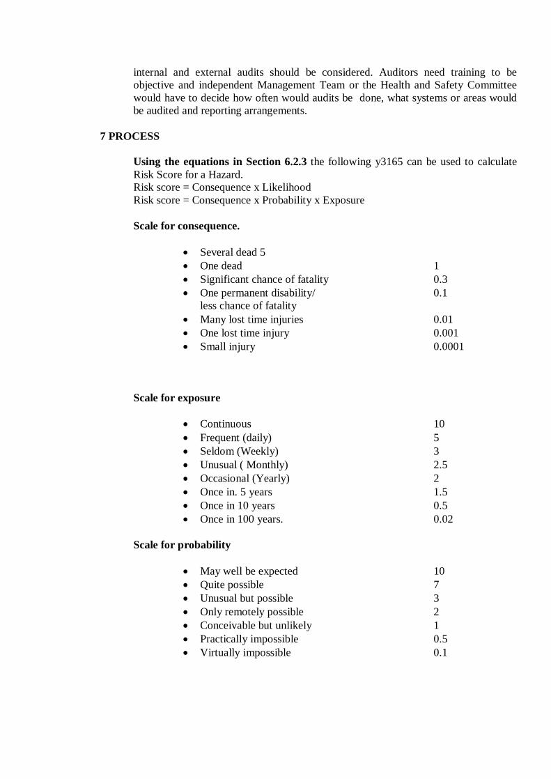
internal and external audits should be considered. Auditors need training to be objective and independent Management Team or the Health and Safety Committee would have to decide how often would audits be done, what systems or areas would be audited and reporting arrangements.
7 PROCESS Using the equations in Section 6.2.3 the following y3165 can be used to calculate Risk Score for a Hazard. Risk score = Consequence x Likelihood Risk score = Consequence x Probability x Exposure Scale for consequence.
Several dead 5 One dead 1 Significant chance of fatality 0.3 One permanent disability/ 0.1
less chance of fatality Many lost time injuries 0.01 One lost time injury 0.001 Small injury 0.0001
Scale for exposure
Continuous 10 Frequent (daily) 5 Seldom (Weekly) 3 Unusual ( Monthly) 2.5 Occasional (Yearly) 2 Once in. 5 years 1.5 Once in 10 years 0.5 Once in 100 years. 0.02
Scale for probability
May well be expected 10 Quite possible 7 Unusual but possible 3 Only remotely possible 2 Conceivable but unlikely 1 Practically impossible 0.5 Virtually impossible 0.1

CONCLUSION
Management of safety issues based on assessment of risks not only, integrates safety with productivity but also can be used as a very good tool for-.reduction of costs. The systems stand on the premise that.all risks need not be eliminated and different control measures can be adopted for different levels of risks. The key here, is to aim for ALARA (as low as reasonably achievable), which eventually depends on cost considerations. The system allows prioritisation of allocation of scarce resources thereby cutting costs and reducing wastages. This assumes great importance in the current Indian scenario.
The other merits of the system are that it is created by the mine operators themselves through considerable brainstorming. This approach let the mine operators/users feel ownership of the system, something that is not cast upon horn by experts. Govt. agencies or outsiders, and hence chances of successful implementation is much more. In this system, grey areas are minimized; responsibilities for action are pinpointed and scopes for auditing and improvements are always present.
Per conveniences of the mine operators different forms for risk assessment its control and audit is enclosed in Anhexure-1. "A Risk Management Plan designed by the officials of a coal mine is given in the Annexure-II for understanding the actual process. This Is given as guide only and need to be tailored for specific requirements.

Previous Home Next