presentation.pptx
TRANSCRIPT

Team 048Gary Brooks, Aashish Murti, Alex Meier, James Brodovsky, Kushagra
PundeerAdviser: Dr Ajmal Yousuff
SAE Aero Design East
Drexel University
Regular Class

Design Objectives● Weight no more than 65 pounds including payload.
● Length, width, and height must not exceed 175 inches.
● Payload must be retained and secured to the frame.
● The closed payload bay must measure 4 x 4 x 10 inches.
● Takeoff with in 200 feet and land within 400 feet.
● Single electric motor may be used.
● Powered by a single Li-Po 4 cell battery
○ Minimum 4000 mAh and 25 C.
● 1,000 Watt power limiter with a shunt plug incorporated into power circuit

Airfoil Analysis
(Cl / Cd vs Alpha)
●XFLR5 and XFOIL used for analysis.
●High Glide ratio (lift to drag ratio) for S1223 (red line)

Airfoil Analysis(Cl vs alpha)
●Higher lift at lower angle of attack
●High aerodynamic performance and efficiency
●Cl = 2.20
●Cd = 0.04

Airfoil Analysis(Cm vs. alpha)
● Negative Cm value of 0.25
● Negative lift from tail section to balance -ve Cm of wing.
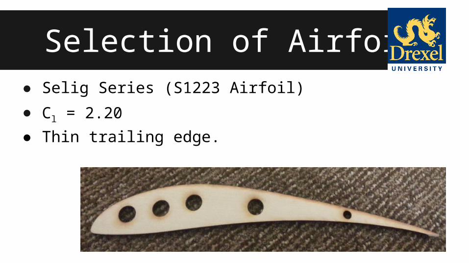
Selection of Airfoil● Selig Series (S1223 Airfoil)
● Cl = 2.20
● Thin trailing edge.

PROPULSIONBattery/Motor
● Battery: 14.8 V, 70C, 6300 mAh, 4s LiPo Battery● Motor: Scorpion SII 3026-890 KV Outrunner● Propeller: 14 x 7 inches

Static Thrust● Density Ratio,δ = ρ / ρ0
● Static Thrust Coefficient, CT = 0.074δ-0.57
● Static Thrust = T(STATIC) = CTρn2D4

Dynamic Thrust
● Pitch speed = RPM*propeller pitch = 13172 RPM * 7 inch =
92204 inch/min = 87.31 mph
● TDYNAMIC = TSTATIC( 1 – (Take Off Speed / Pitch Speed))
● TDYNAMIC = 69.23(1 – (37.11/87.31)) = 7.22 lbs.

Wing design
• Set AR = 7, CL = 2.0, T = 15 lbs.
• Varied T/W until weight of ~65 lbs was derivedo Yields minimum W/S
• W/S increased to find a suitable S, b, c

Wing design
• Given:o s = 150
fto CL=2.0o AR = 7
• General Parameters:o T/W = 0.230o W/S = 9.25 psio S = 7.00 ft2
o b = 7.00 fto c = 1.00 ft

Material SelectionAirfoil:
Current Choice - Basswood• Basswood is sturdy enough to perform at the geometry of the
specified airfoil.
Wing Spar:Current Choice - Maple
• Maple was able to keep the wing form and maintain an appropriate dihedral angle.
Framework:Current Choice - Basswood
• Basswood has a good strength to weight ratio, it has the lowest density while maintaining performance.

Finite Element AnalysisWing structure with Maple spars - deflection of
approximately 2.5 inches

Finite Element AnalysisLanding Gear made from Aluminum
Ultimate Tensile Strength
4.4 x 10⁸
Maximum Stress(Von Mises)
4.6 x 10⁷

Configuration
• Conventional• Tractor Propeller
• High Wing
• Tail Dragger Landing

Component Placement

Aircraft Stability and Control

Aircraft Stability and Control
● Neutral point = 16.84 in.
● XAC= 16.45 in.
● Static Margin = (X_CG - XAC)/c_bar
● Dihedral ~ 6 degree

Performance PredictionTake off Distance: No Wind = 150 ft.
Landing Distance: No Wind = 250 ft.
Payload • Payload consists of welded steel plates.• At minimum weight (10 lbs): stability of
35.37%• Maximum of 39 lbs, ~12% stability
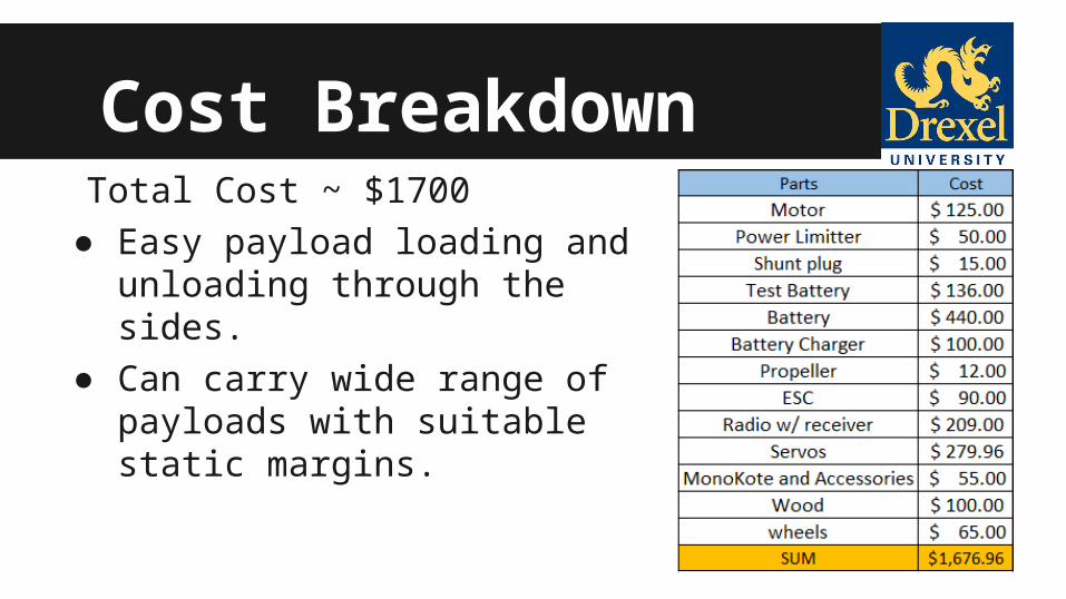
Cost BreakdownTotal Cost ~ $1700
● Easy payload loading and unloading through the sides.
● Can carry wide range of payloads with suitable static margins.

Acknowledgements• Our advisor Dr. Ajmal Yousuff• Drexel Space Systems Laboratory• AIAA• NASA Space Grant• Drexel Machine Shop• Drexel MEM and ECE Departments

Questions?
