presentation on surface investigation techniques for foundation
TRANSCRIPT

PRESENTATION ON SURFACE INVESTIGATION TECHNIQUES FOR FOUNDATIONBY ASHISH KUMAR VERMA
CIVIL 4TH YEAR (1236300032)

WHY TO INVESTIGATE SURFACE?
• Before deciding any foundation it is essential to obtain reliable and sufficient data about the strata ,where foundation will be located .if a site is to be chosen from large area , or from alternative areas ,such as selection of site for dam,bridge ,tunnels,highway etc. It is necessary that proper soil exploration is carried out.
• Such exploration will enable the designer to provide viable and economical design .although the cost of exploration is usually less than1 to 2% the project cost,in most of the cases ,exploration is not given due to attention , which may prove to be un economical and disastrous in long run.

TABLE OF CONTENTS • 1.INTRODUCTION• 2.SOIL EXPLORATION AND SITE INVESTIGATION• 3.STEPS IN SOIL EXPLORATION• 4.METHODS OF OBTAINING SOIL SAMPLES• 5.TRIAL PITS AND TRENCHES• 6.AUGER BORING• 7.WASH BORING• 8.ROTARY DRILLING(CORE BORING OR CORE
DRILLING)• 9.PERCUSSION DRILLING• 10.STANDARD PENETRATION TEST(SPT)• 11.DYNAMIC CONE PENETRATION TEST(DCPT)

SOIL EXPLORATION AND SITE INVESTIGATIONThe basic aim of sub surface exploration or site investigation is obtain the information about the surface conditions at the site of proposed construction .For beneficial for the design of structures and for planning construction techniques
.• FACTORS AFFECTING EXPLORATION PROGRAMME• Soil exploration programme are influenced by a number of
factors some of these are:• a) Size and type of the project;• b) General characteristics of the soils in the work area;• c) Time available for exploration; and• d) Degree of risk or safety involved.

• CLASSES• Sub-surface investigations may be subdivided into three
classes:• a) Foundation investigations to investigate sites for new
structures.• b) Stability or failure investigations to investigate causes
of distress or failure of existing structures.• c) Earthwork investigations to evaluate suitability of
natural materials for construction purposes.

SITE INVESTIGATION

STEPS IN SOIL EXPLORATION• The procedure of exploration can be divided into the following
steps:• 1) RECONNAISSANCE:• i) Collection of data about the project.• ii) Geologic study of the site.• iii) Site inspection• The procedure of exploration can be divided into the following
steps:• 2) PRELIMINARY EXPLORATION:• • i) Depth, extent, and composition of critical soil strata,• ii) Ground-water level and its fluctuations,• iii) Depth of bed rock, when necessary,• iv) Estimate of engineering properties of soil,• v) Initial selection of foundation possibilities.
• 3) DETAILED EXPLORATION:• • i) Additional test borings.• ii) Undisturbed sampling if compressible soils are
encountered at critical depth.• iii) Laboratory/Field tests if data on soil strength and
deformation characteristics are needed.
• 4) ANALYSIS OF RESULTSOF EXPLORATION:• • i) Evaluation of settlement characteristics of various soil
layers.• ii) Evaluation of bearing capacity of various soil layers.

METHODS OF OBTAINING SOIL SAMPLES• TRIAL PITS AND TRENCHES• Trial pits shall have nominal plan dimensions of 1.5 m x
1.5 m to their full depth of excavation, unless otherwise instructed by the Engineer or due to restricted space at the pit location or where prevented by the presence of hard strata. Where trial pits are excavated on sloping ground the base of each pit shall be horizontal and any instructed termination depth shall be taken as the depth of excavation at the mid-point of the base to original ground level. Any trial pit or trial trench left open overnight, shall be provided with both a strong wooden cover securely battened down and appropriate fencing to prevent persons and animals from falling into the excavation.

AUGER BORING• Auger Boring is a technique for the bored installation of a casing pipe into the
ground. Product pipe or final services are then installed within the casing pipe as required. It could be described as a Pipe jacking technique but as the casing pipe is an integral part of the construction methodology it has been decided to give it its own section within the ISTT Guidelines. The technique is normally found to be cheaper than full microtunnelling or pipe jacking but does have limitation on the range of ground in which it can operate effectively in its standard form, in particular very wet ground, but with special adaptation can operate in ground including rock. Depth limits are dependent on the size of excavation required to access the auger boring unit and the practical length of pipe that can be installed from what is generally quite a large dimension launch shaft/pit.
• • As the name Auger Boring implies, the excavation technique employed is that of
using a rotating auger chain/flight fitted with a cutter head. The cutter head is driven by, and is positioned at the lead end of, an auger string that has been established within the casing pipe, the auger diameter being dimensioned to the just below the full diameter of the casing to allow rotation. Rotating the helical auger chain within the casing pipe allows the cutter head to excavate the ground at the face, with spoil being removed back along the auger string within the casing pipe to the launch shaft or pit. Spoil is removed by hand or mechanically or placed into muck skips for removal as it exits the casing pipe.

• The system is normally an unguided technique and is not generally used for installations requiring very high accuracy in line and level, although experienced operators can achieve very good accuracy where ground conditions permit. Some systems have been developed that allow for some limited steering capability to be applied to the cutter head or to the casing pipe to counter minor deviations as they occur.
• The system is normally applied to the softer ground conditions like clay soils and soils with contained cobbles. Some systems have been designed to handle softer rock formations with the use of a special cutter head, and as time progresses rock capability is improving. High water table and flowing ground does cause auger boring a problem as the auger flight is not generally a sealed system and the auger chain is the only means of preventing loss of ground
• from the face and is neither water tight nor sealable.

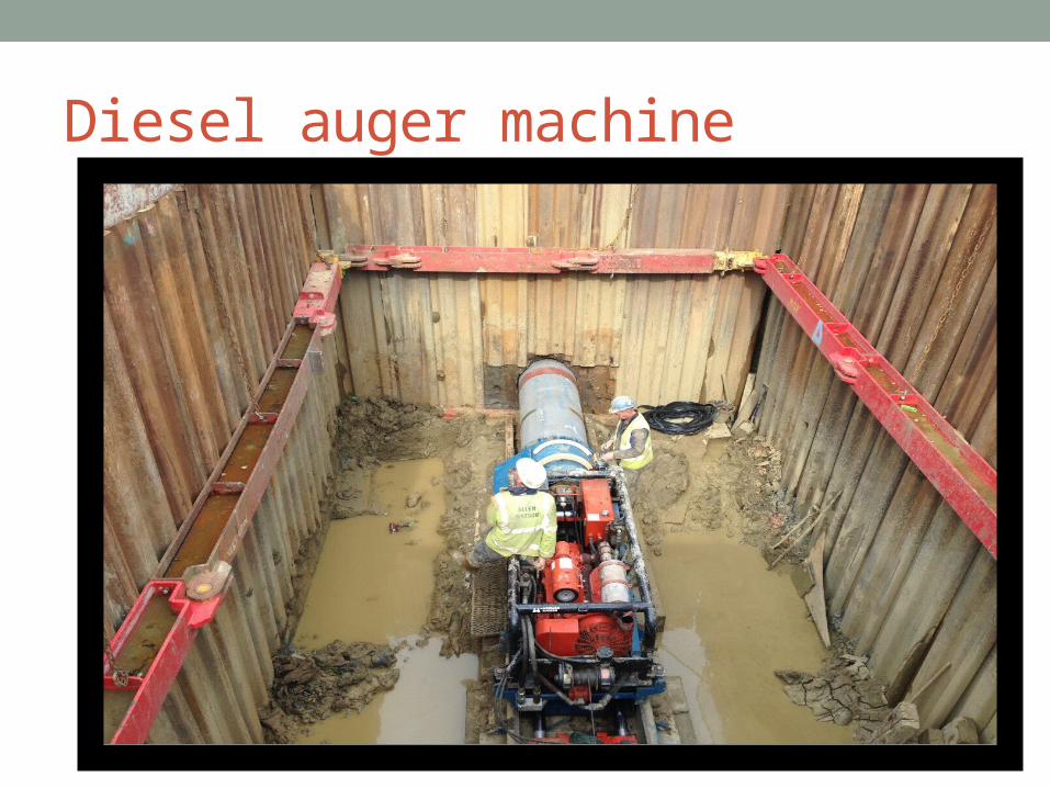
Diesel auger machine

WASH BORING• It is a popular method due to the use of limited equipments. The
advantage of this is the use of inexpensive and easily portable handling and drilling equipments. Here first an open hole is formed on the ground so that the soil sampling or rock drilling operation can be done below the hole. The hole is advanced by chopping and twisting action of the light bit. Cutting is done by forced water and water jet under pressure through the rods operated inside the hole. In India the “Dheki” operation is used, i.e., a pipe of 5cm diameter is held vertically and filled with water using horizontal lever arrangement and by the process of suction and application of pressure, soil slurry comes out of the tube and pipe goes down. This can be done upto a depth of 8m –10m (excluding the depth of hole already formed beforehand) Just by noting the change of colour of soil coming out with the change of soil character can be identified by any experienced person. It gives completely disturbed sample and is not suitable for very soft soil, fine to medium grained cohesionless soil and in cemented soil.


ROTARY DRILLING
• Rotary drilling method of boring is useful in case of highly resistant strata. It is related to finding out the rock strata and also to access the quality of rocks from cracks, fissures and joints. It can conveniently be used in sands and silts also. Here, the bore holes are advanced in depth by rotary percussion method which is similar to wash boring technique. A heavy string of the drill rod is used for
• choking action. The broken rock or soil fragments are removed by circulating water or drilling mud pumped through the drill rods and bit up through the bore hole from which it is collected in a settling tank for recirculation. If the depth
• is small and the soil stable, water alone can be used. However,drilling fluids are useful as they serve to stabilize the bore hole.
• Drilling mud is slurry of bentonite in water. The drilling fluid causes stabilizing effect to the bore hole partly due to higher specific gravity as compared with water and partly due to formation of mud cake on the sides of the hole. As the
• stabilizing effect is imparted by these drilling fluids no casing is required if drilling fluid is used. This method is suitable for boring holes of diameter 10cm, or more preferably 15 to20cm in most of the rocks. It is uneconomical for
• holes less than 10cm diameter. The depth of various strata can be detected by inspection of cuttings.

• ADVANTAGES:• • 1.Rotary drilling can be used in clay ,sand and rocks• • 2.Bore holes of diameter 50mm to 200mm can be easily
drilled by this method• • • DISADVANTAGE:• • If soil is containing a large percentage of particles of gravel
size and larger ,this method is not well adopted . Because ,the particles of this size start rotating below the drill rod and it becomes difficult to drill the hole.
•


PERCUSSION DRILLING• In case of hard soils or soft rock, auger boring or wash boring cannot
be employed. For such strata, percussion drilling is usually adopted. Here advancement of hole is done by alternatively lifting and dropping a heavy drilling bit which is attached to the lower end of the drilling bit which is attached to the cable. Addition of sand increases the cutting action of the drilling bit in clays. Whereas, when coarse cohesionless soil is encountered, clay might have to be added to increase the carrying capacity of slurry. After the carrying capacity of the soil is reached, churn bit is removed and the slurry is removed using bailers and sand pumps. Change in soil character is identified by the composition of the outgoing slurry. The stroke of bit varies according to the ground condition. Generally, it is 45-100cm in depth with rate of 35-60 drops/min. It is not economical for hole of diameter less than 10cm. It can be used in most of the soils and rocks and can drill any material. One main disadvantage of this process is that the material at the bottom of the hole is disturbed by heavy blows of the chisel and hence it is not possible to get good quality undisturbed samples. It cannot detect thin strata as well.

• ADVANTAGES:• • 1.percussion drilling can be used in all types of soil • • • 2.it is very useful for boring holes like that for tube well through rock or • Boulders.• • • DISADVANTAGES• • 1.Because of heavy blows of the chisel ,the material at the bottom is in
disturbed state.• • 2.more expensive as compared to other methods • • 3.Diffcult to detect minor changes in the properties of the strata
penetrated.


STANDARD PENETRATION TEST (SPT)• The standard penetration test (SPT) is an in-situ dynamic
penetration test designed to provide information on the geotechnical engineering properties of soil.
• The test uses a thick-walled sample tube, with an outside diameter of 50 mm and an inside diameter of 35 mm, and a length of around 650 mm. This is driven into the ground at the bottom of a borehole by blows from a slide hammer with a mass of 63.5 kg (140 lb) falling through a distance of 760 mm (30 in). The sample tube is driven 150 mm into the ground and then the number of blows needed for the tube to penetrate each 150 mm (6 in) up to a depth of 450 mm (18 in) is recorded. The sum of the number of blows required for the second and third 6 in. of penetration is termed the "standard penetration resistance" or the "N-value". In cases where 50 blows are insufficient to advance it through a 150 mm (6 in) interval the penetration after 50 blows is recorded. The blow count provides an indication of the density of the ground, and it is used in many empirical geotechnical engineering formulae.

• The main purpose of the test is to provide an indication of the relative density of granular deposits, such as sands and gravels from which it is virtually impossible to obtain undisturbed samples. The great merit of the test, and the main reason for its widespread use is that it is simple and inexpensive. The soil strength parameters which can be inferred are approximate, but may give a useful guide in ground conditions where it may not be possible to obtain borehole samples of adequate quality like gravels, sands, silts,clay containing sand or gravel and weak rock. In conditions where the quality of the undisturbed sample is suspect, e.g., very silty or very sandy clays, or hard clays, it is often advantageous to alternate the sampling with standard penetration tests to check the strength. If the samples are found to be unacceptably disturbed, it may be necessary to use a different method for measuring strength like the plate test. When the test is carried out in granular soils below groundwater level, the soil may become loosened. In certain circumstances, it can be useful to continue driving the sampler beyond the distance specified, adding further drilling rods as necessary. Although this is not a standard penetration test, and should not be regarded as such, it may at least give an indication as to whether the deposit is really as loose as the standard test may indicate.

• The usefulness of SPT results depends on the soil type, with fine-grained sands giving the most useful results, with coarser sands and silty sands giving reasonably useful results, and clays and gravelly soils yielding results which may be very poorly representative of the true soil conditions. Soils in arid areas, such as the Western United States, may exhibit natural cementation. This condition will often increase the standard penetration value.


DYNAMIC CONE PENETRATION TEST• The Dynamic Cone Penetration Test provides a measure of a
material’s in-situ resistance to penetration. The test is performed by driving a metal cone into the ground by repeated striking it with a 17.6 lb (8 Kg)weight dropped from a distance of 2.26 feet (575 mm). The penetration of the cone is measured after each blow andis recorded to provide a continuous measure of shearing resistance up to 5 feet below the ground surface. Test results can be correlated to California Bearing Ratios, in-situ density, resilient modulus, and bearing capacity.
• • The cost of purchasing or manufacturing a DCP test apparatus is
relatively low. Currently, prices vary from $1,600 to $2,200 USD for portable hand-operated equipment. More expensive, automated DCP rigs can be purchased that are towable. Depending on the DCP apparatus the test can be conducted efficiently with as little as 1 to 2 people. Again, dependent upon the test apparatus, depth of testing, and the condition of the subgrade, the test requires 5 to 10 minutes to complete.

• The DCP apparatus consists of a 5/8”-inch diameter steel rod with a 60 degree conical tip. The rod is topped with an anvil that is connected to a second steel rod. This rod is used as a guide to allow an 8kg hammer to be repeatedly raised and dropped from a height of 575mm. The connection between the two rods consists of anvil to allow for quick connections between the rods and for efficient energy transfer from the falling weight to the penetrating rod.
• Once the test apparatus is assembled the DCP is placed at the test location and the initial penetration of the rod is recorded to provide a zeroing scale. While holding the rod vertically, the weight is raised to the top of the rod 575 mm above the anvil and dropped. The penetration of the rod is measured after each drop. In cohesive soils the penetration rod may be rotated slightly to prevent binding of the soil and the rod influencing test results. The test shall be terminated if the desired depth is reached or if the rod penetrates less than 1/8-inch in 10 drops.


THANK YOU