prepstar sd-1 solvent delivery system - agilent · varian prepstar sd-1 solvent delivery system...
TRANSCRIPT
PrepStar SD-1 Solvent Delivery System
Operation Manual
Installation Category II Pollution Degree 2 Safety Class 1 (EN 61010-1)
Publication no. 0391479400 Issue 6 June 2010
Varian PrepStar SD-1 Solvent Delivery System Operation Manual
ii Publication no. 0391479400, Issue 6, June 2010
Varian, Inc. – Serving Industries Worldwide
Biosciences
Pharmaceuticals
Clinical Research and Forensics
Food and Agriculture
Chemical Analysis
Environmental
Fuels and Energy
Material Sciences
Sales and Service Contact Details
North America: 800.926.3000, 925.939.2400
Europe, The Netherlands: 31.118.67.1000
Asia Pacific, Australia: 613.9560.7133
Latin America, Brazil: 55.11.3238.0400
Varian, Inc. Web Site
www.varianinc.com
Varian, Inc. is the owner of copyright on this document and any associated software. Under law, the written permission of Varian, Inc. must be obtained before the documentation or the software is copied, reproduced, translated or converted to electronic or other machine-readable form, in whole, or in part.
First published May 2000. Updated July 2008 and June 2010.
PrepStar, Dynamax, ProStar and Varian and the Varian logo are trademarks or registered trademarks of Varian, Inc. in the U.S. and other countries.
© 2000-2010 Varian Inc.
Varian PrepStar SD-1 Solvent Delivery System Operation Manual
Publication no. 0391479400, Issue 6, June 2010 iii
Table of Contents
Safety Information 1
Operating Instructions 1
General Safety Precautions 3
Electrical Hazards 3
Compressed Gas Cylinders 4
High Pressure Hazard 4
Flash Chromatography 5
Ultraviolet Radiation 5
Varian, Inc. Analytical Instruments Sales Offices 6
1. Introduction 7
1.1 Description 7
2. Installation 9
2.1 Unpacking 9
2.2 Location 10
2.3 Quick Set Up 10
2.3.1 Electrical Connections 11
2.3.2 Plumbing Connections 11
2.4 Electrical Setup 15
2.4.1 Fuse/Line Voltage 15
2.4.2 Power Connection 15
2.4.3 External Contacts Panel 16
2.4.4 Serial Interface Connections for Remote Control 19
2.5 Plumbing the PrepStar SD-1 Solvent Delivery System 20
2.5.1 Low Pressure Solvent Inlet 21
2.5.2 High Pressure Outlet 22
2.5.3 Priming the PrepStar SD-1 22
Varian PrepStar SD-1 Solvent Delivery System Operation Manual
iv Publication no. 0391479400, Issue 6, June 2010
2.6 Plumbing the HPLC system 23
2.6.1 General 23
2.6.2 Isocratic HPLC Systems 24
2.6.3 Gradient HPLC Systems 25
2.6.4 AutoPrep HPLC System 27
2.7 Initial Operation 28
3. Instrument Description 33
3.1 Front View 33
3.2 Back View 35
3.3 Keypad 36
3.4 SD-1 Displays 38
3.4.1 Cursors 38
3.4.2 HOME Display 39
3.4.3 Main Displays 40
3.4.4 Special Displays 41
4. Operation 45
4.1 Safety Considerations 45
4.1.1 Operator Safety 45
4.1.2 Instrument Considerations 45
4.2 Initial Operation 46
4.2.1 Power Up 47
4.2.2 Flush the HPLC System 47
4.2.3 Check for Leaks Against System Backpressure 48
4.3 Setting Flow and Maximum Pressure 49
4.3.1 Power Up 49
4.3.2 Setting Maximum Pressure 49
4.4 Changing the Liquid Heads 50
4.4.1 Pressure Conversions 51
4.4.2 Interchangeable Liquid Heads 51
4.4.3 Liquid Head Removal 52
Varian PrepStar SD-1 Solvent Delivery System Operation Manual
Publication no. 0391479400, Issue 6, June 2010 v
4.4.4 Liquid Head Replacement 54
4.5 Remote Operation 56
5. Maintenance and Troubleshooting 57
5.1 Maintenance 57
5.2 Service Logs 57
5.2.1 Piston Seal Log Display 57
5.2.2 Check Valve Log Display 58
5.2.3 Pump Drive Log Display 58
5.3 Seal Replacement 58
5.3.1 Dismantling the Liquid Head 60
5.3.2 Removing Seals/O-ring 61
5.3.3 Replacing Seals/O-ring 61
5.4 Piston Replacement 63
5.4.1 Removing the Old Piston Assembly 64
5.4.2 Installing the New Piston Assembly 64
5.5 Check Valve Replacement 64
5.5.1 Cleaning the Check Valves 66
5.5.2 Removing the Check Valves 66
5.5.3 Installing the Check Valve Cartridge 66
5.5.4 Replacing the Check Valve 68
5.6 Fuse Replacement 69
5.7 Troubleshooting 70
5.7.1 “Reading” the Pressure Display 70
5.8 Troubleshooting Guides 72
5.9 Error Messages 75
6. Appendix 77
6.1 Specifications 77
6.1.1 Pump Head Kits 77
6.1.2 General Specifications 77
6.2 Maximum Pressure vs. Flow 79
Varian PrepStar SD-1 Solvent Delivery System Operation Manual
vi Publication no. 0391479400, Issue 6, June 2010
6.3 Liquid Head Part Numbers 79
6.4 Accessories 80
6.5 Replacement Parts 80
6.5.1 For 50 mL Head 80
6.5.2 For 200 mL Head 81
6.5.3 For 500 mL Head 81
6.5.4 For 800 mL Head 82
6.5.5 For 3.2L Head 82
6.6 Scale-Up 83
6.7 System Requirements for High Performance Prep Chromatography 83
6.8 Scale-Up HPLC System 85
6.9 The Scale-Up Process 85
Varian PrepStar SD-1 Solvent Delivery System Operation Manual
Publication no. 0391479400, Issue 6, June 2010 1 of 88
Safety Information
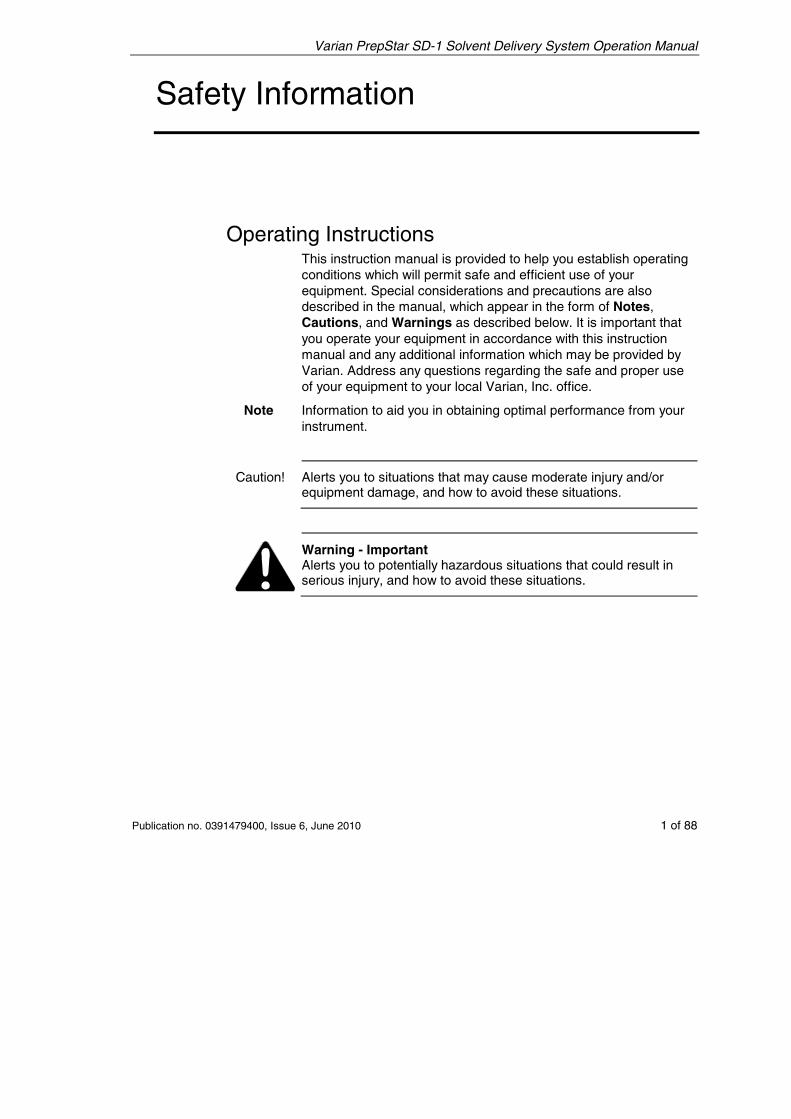
Operating Instructions This instruction manual is provided to help you establish operating conditions which will permit safe and efficient use of your equipment. Special considerations and precautions are also described in the manual, which appear in the form of Notes, Cautions, and Warnings as described below. It is important that you operate your equipment in accordance with this instruction manual and any additional information which may be provided by Varian. Address any questions regarding the safe and proper use of your equipment to your local Varian, Inc. office.
Note Information to aid you in obtaining optimal performance from your instrument.
Caution! Alerts you to situations that may cause moderate injury and/or equipment damage, and how to avoid these situations.
Warning - Important Alerts you to potentially hazardous situations that could result in serious injury, and how to avoid these situations.
Varian PrepStar SD-1 Solvent Delivery System Operation Manual
2 of 88 Publication no. 0391479400, Issue 6, June 2010
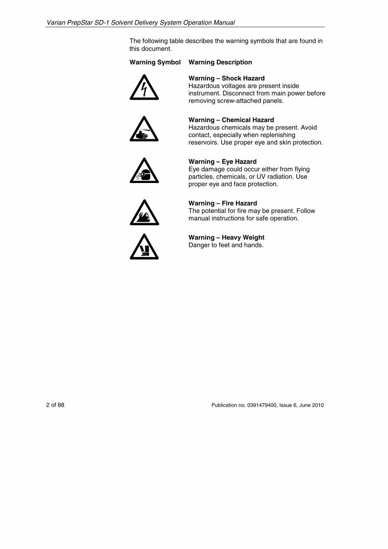
The following table describes the warning symbols that are found in this document.
Warning Symbol Warning Description
Warning – Shock Hazard Hazardous voltages are present inside instrument. Disconnect from main power before removing screw-attached panels.
Warning – Chemical Hazard Hazardous chemicals may be present. Avoid contact, especially when replenishing reservoirs. Use proper eye and skin protection.
Warning – Eye Hazard Eye damage could occur either from flying particles, chemicals, or UV radiation. Use proper eye and face protection.
Warning – Fire Hazard The potential for fire may be present. Follow manual instructions for safe operation.
Warning – Heavy Weight Danger to feet and hands.
Varian PrepStar SD-1 Solvent Delivery System Operation Manual
Publication no. 0391479400, Issue 6, June 2010 3 of 88
General Safety Precautions Follow these safety practices to ensure safe equipment operation.
• Perform periodic leak checks on all supply lines and pneumatic plumbing.
• Do not allow gas lines to become kinked or punctured. Place lines away from foot traffic and extreme heat or cold.
• Store organic solvents in fireproof, vented and clearly labeled cabinets so they are easily identified as toxic and/or flammable materials.
• Do not accumulate waste solvents. Dispose of such materials through a regulated disposal program and not through municipal sewage lines.
NOTICE: This instrument has been tested per applicable requirements of EMC Directive as required to carry the European Union CE Mark. As such, this equipment may be susceptible to radiation/interference levels or frequencies which are not within the tested limits.
Warning - Important This instrument is designed for chromatographic analysis of appropriately prepared samples. It must be operated using appropriate gases and/or solvents and within specified maximum ranges for pressure, flows, and temperatures as described in this manual. If the equipment is used in a manner not specified by the manufacturer, the protection provided by the equipment may be impaired.
Warning - Important It is your responsibility inform Varian representatives if the instrument has been used for the analysis of hazardous biological, radioactive, or toxic samples, prior to any instrument service being performed or when an instrument is being returned to the Service Center for repair.
Electrical Hazards • Disconnect the instrument from all power sources before
removing protective panels to avoid exposure to potentially dangerous voltages.
• When it is necessary to use a non-original power cord plug, make sure the replacement cord adheres to the color coding
Varian PrepStar SD-1 Solvent Delivery System Operation Manual
4 of 88 Publication no. 0391479400, Issue 6, June 2010
and polarity described in the manual and all local building safety codes.
• Replace blown fuses with fuses of the size and rating stipulated on the fuse panel or in the manual.
• Replace faulty or frayed power cords immediately with the same type and rating.
• Make sure that voltage sources and line voltage match the value for which the instrument is wired.
Compressed Gas Cylinders • Store and handle compressed gases carefully and in strict
adherence to safety codes.
• Secure cylinders to an immovable structure or wall.
• Store and move cylinders in an upright, vertical position. Before transport, remove regulators and install cylinder cap.
• Store cylinders in a well-ventilated area away from heat, direct sunshine, freezing temperatures, and ignition sources.
• Mark cylinders clearly.
• Use only approved regulators and connections.
• Use only connector tubing that is chromatographically clean (Varian part number 0391832600) and has a pressure rating significantly greater than the highest outlet pressure from the regulator.
High Pressure Hazard • If a line ruptures, a relief device opens, or a valve opens
accidentally under pressure, potentially hazardous high liquid pressures can be generated by the pump causing a high velocity stream of volatile and/or toxic liquids.
• Wear face protection when you inject samples or perform routine maintenance.
• Never open a solvent line or valve under pressure. Stop the pump first and let the pressure drop to zero.
• Use shatter-proof reservoirs capable of operating at 345-415 kPa (50-60 psi).
• Keep the reservoir enclosure closed when the reservoir is under pressure.
• Read and adhere to all Notes, Cautions, and Warnings in the manual.
Varian PrepStar SD-1 Solvent Delivery System Operation Manual
Publication no. 0391479400, Issue 6, June 2010 5 of 88
Flash Chromatography The operator should be familiar with the physico-chemical properties of the components of the mobile phase.
Keep solvents from direct contact with the polyurethane supply tubing as certain solvents will cause weakening and leaks with possible bursting.
All components of the system should be connected to a common power supply and common ground. This ground must be a true ground rather than a floating ground.
Non-polar solvents can develop a static charge when pumped through the system. All vessels that contain mobile phase (including tubing and collection vessels) must be grounded to dissipate static electricity.
Employ static measuring and static discharge devices (e.g., air ionizers) to safeguard against the buildup of static electricity.
Ultraviolet Radiation Liquid chromatograph detectors that use an ultraviolet light source have shielding to prevent radiation exposure to personnel.
For continued protection ensure that protective lamp covers of variable and fixed wavelength detectors are in place during operation.
Do not look directly into detector fluid cells or at the UV light source. When inspecting the light source or fluid cell, always use protective eye covering such as borosilicate glass or polystyrene.
Varian PrepStar SD-1 Solvent Delivery System Operation Manual
6 of 88 Publication no. 0391479400, Issue 6, June 2010
Varian, Inc. Analytical Instruments Sales Offices For Sales or Service assistance and to order Parts and Supplies, contact your local Varian office.
Argentina Buenos Aires Tel. +54.11.4.796.9400
Australia Mulgrave, Victoria Tel. +61.3.9560.7133
Austria Poettelsdorf Tel. +43.0.2626.20090
Brazil and Latin America (S) São Paulo Tel. +55.11.3238.0400
Canada Mississauga, Ontario Tel. 800.387.2216
China Beijing Tel. +86.106310.8550
Europe Middelburg, The Netherlands Tel. +31.118.671.500
France Les Ulis Cédex Tel. +33.1.6986.3838
Germany Darmstadt Tel. +49.6151.7030
India Mumbai Tel. +91.22.2570.8595
Italy Torino Tel. +39.11.997.9111
Japan Tokyo Tel. +81.3.5232.1239
Korea Seoul Tel. +82.2.345.22452
Mexico and Latin America (N) Mexico City Tel. +52.5.523.9465
Russian Federation Moscow Tel. +7.095.937.4280
Spain Madrid Tel. +34.91.472.7612
Sweden Solna Tel. +46.8.445.1620
Switzerland Varian AG Tel. +41.848.803.800
Taiwan Taipei Hsien Tel. +886.22.698.9555
United Kingdom and Ireland Yarnton, Oxford Tel. +44.01865.291500
Venezuela Puerto Ordaz, Bolívar Tel. +58.41.257.608
United States Walnut Creek, California, USA Tel. +1.800.926.3000 or +1.925.939.2400
www.varianinc.com
Varian PrepStar SD-1 Solvent Delivery System Operation Manual
Publication no. 0391479400, Issue 6, June 2010 7 of 88
1. Introduction
1.1 Description The PrepStar SD-1 is an innovative HPLC solvent delivery system engineered with preparative chromatographers in mind. A powerful drive unit and dual interchangeable pump heads provide pumping capacity to 3.2 L per minute at pressures of up to 2.6 MPa (375 psi) for superior throughput with large high-resolution microparticulate columns. For bench-scale prep, 200 mL per minute and 50 mL per minute heads provide flow at pressures up to 41.4 MPa (6000 psi) and 68.9 MPa (10,000 psi), respectively. Corrosion-resistant titanium pump heads address the needs of biochemists for compatibility with salt-containing buffers and freedom from unwanted metal ions. Each pump head has a piston washing chamber to prevent deposition of abrasive salt residues behind the high-pressure seal, thereby greatly extending seal life.
Major new technology includes dual independent linear piston drives. Rather than operating both heads from cams attached to a single motor, as in conventional dual piston pumps, the SD-1 uses two independent stepper motors which connect to pistons via linear screw drives. The motors reciprocate, rather than running only in one direction. Independent drive frees the SD-1 from the operating constraints of mechanical cam profiles and makes it the first dual piston pump to produce entirely pulse-free flow under all operating conditions, without auxiliary hydromechanical pulse dampers. Totally pulse-free flow favors improved column performance and extended column life by saving expensive preparative columns from the constant pressure-pulse pounding typical of other large piston and diaphragm pumps.
In addition, the SD-1 meters flow at a constant rate independent of solvent compressibility and without the slight refill-associated flow deficits seen with conventional single-motor dual-piston models. In gradient operation, this produces more precise composition profiles without the time and volume delays introduced by large mixing chambers. Plus, flow rates extend well into the analytical HPLC
Varian PrepStar SD-1 Solvent Delivery System Operation Manual
8 of 88 Publication no. 0391479400, Issue 6, June 2010
range, permitting method development on smaller columns without interchanging heads.
Each SD-1 pump includes a standard serial interface for flow control. A built-in two-channel analog-to-digital converter allows the computer to collect data from HPLC detectors. Contact closure inputs and outputs are provided for system automation. Firmware includes GLP logging features.
Varian PrepStar SD-1 Solvent Delivery System Operation Manual
Publication no. 0391479400, Issue 6, June 2010 9 of 88
2. Installation
2.1 Unpacking
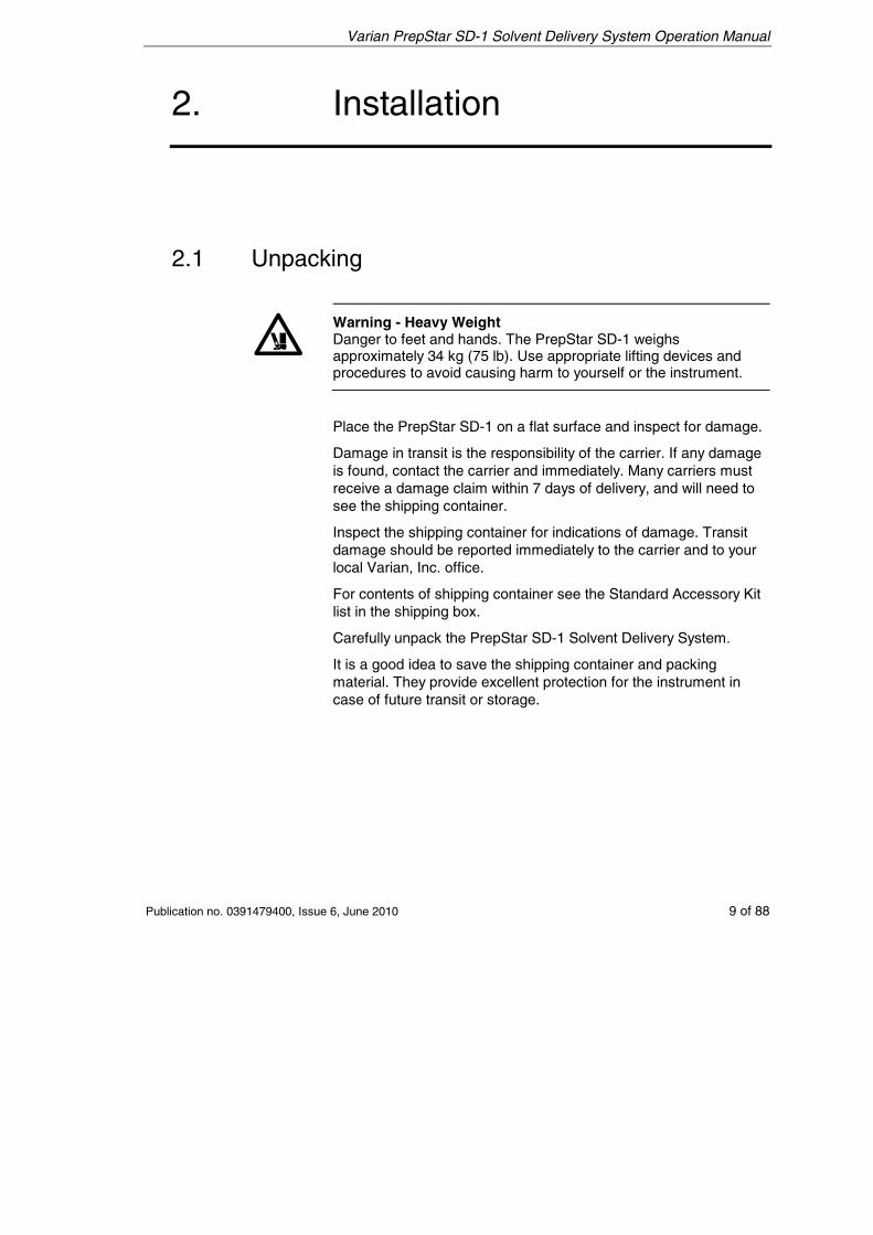
Warning - Heavy Weight Danger to feet and hands. The PrepStar SD-1 weighs approximately 34 kg (75 lb). Use appropriate lifting devices and procedures to avoid causing harm to yourself or the instrument.
Place the PrepStar SD-1 on a flat surface and inspect for damage.
Damage in transit is the responsibility of the carrier. If any damage is found, contact the carrier and immediately. Many carriers must receive a damage claim within 7 days of delivery, and will need to see the shipping container.
Inspect the shipping container for indications of damage. Transit damage should be reported immediately to the carrier and to your local Varian, Inc. office.
For contents of shipping container see the Standard Accessory Kit list in the shipping box.
Carefully unpack the PrepStar SD-1 Solvent Delivery System.
It is a good idea to save the shipping container and packing material. They provide excellent protection for the instrument in case of future transit or storage.
Varian PrepStar SD-1 Solvent Delivery System Operation Manual
10 of 88 Publication no. 0391479400, Issue 6, June 2010
2.2 Location
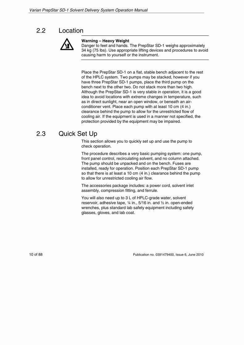
Warning – Heavy Weight Danger to feet and hands. The PrepStar SD-1 weighs approximately 34 kg (75 lbs). Use appropriate lifting devices and procedures to avoid causing harm to yourself or the instrument.
Place the PrepStar SD-1 on a flat, stable bench adjacent to the rest of the HPLC system. Two pumps may be stacked, however if you have three PrepStar SD-1 pumps, place the third pump on the bench next to the other two. Do not stack more than two high. Although the PrepStar SD-1 is very stable in operation, it is a good idea to avoid locations with extreme changes in temperature, such as in direct sunlight, near an open window, or beneath an air-conditioner vent. Place each pump with at least 10 cm (4 in.) clearance behind the pump to allow for the unrestricted flow of cooling air. If the equipment is used in a manner not specified, the protection provided by the equipment may be impaired.
2.3 Quick Set Up This section allows you to quickly set up and use the pump to check operation.
The procedure describes a very basic pumping system: one pump, front panel control, recirculating solvent, and no column attached. The pump should be unpacked and on the bench. Fuses are installed, ready for operation. Position each PrepStar SD-1 pump so that there is at least a 10 cm (4 in.) clearance behind the pump to allow for unrestricted cooling air flow.
The accessories package includes: a power cord, solvent inlet assembly, compression fitting, and ferrule.
You will also need up to 3 L of HPLC-grade water, solvent reservoir, adhesive tape, ¼ in., 5/16 in. and ½ in. open-ended wrenches, plus standard lab safety equipment including safety glasses, gloves, and lab coat.
Varian PrepStar SD-1 Solvent Delivery System Operation Manual
Publication no. 0391479400, Issue 6, June 2010 11 of 88
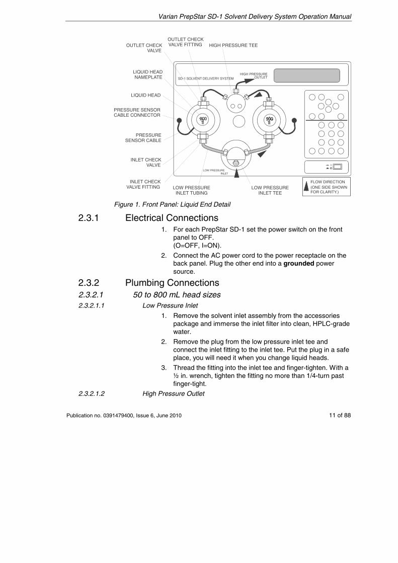
SD-1 SOLVENT DELIVERY SYSTEM
HIGH PRESSURE TEEOUTLET CHECKVALVE FITTINGOUTLET CHECK
VALVE
LIQUID HEADNAMEPLATE
LIQUID HEAD
PRESSURE SENSORCABLE CONNECTOR
PRESSURESENSOR CABLE
INLET CHECKVALVE
INLET CHECKVALVE FITTING LOW PRESSURE
INLET TUBINGLOW PRESSURE
INLET TEE
LOW PRESSUREINLET
HIGH PRESSUREOUTLET
FLOW DIRECTION (ONE SIDE SHOWNFOR CLARITY.)
Figure 1. Front Panel: Liquid End Detail
2.3.1 Electrical Connections 1. For each PrepStar SD-1 set the power switch on the front
panel to OFF. (O=OFF, I=ON).
2. Connect the AC power cord to the power receptacle on the back panel. Plug the other end into a grounded power source.
2.3.2 Plumbing Connections 2.3.2.1 50 to 800 mL head sizes 2.3.2.1.1 Low Pressure Inlet
1. Remove the solvent inlet assembly from the accessories package and immerse the inlet filter into clean, HPLC-grade water.
2. Remove the plug from the low pressure inlet tee and connect the inlet fitting to the inlet tee. Put the plug in a safe place, you will need it when you change liquid heads.
3. Thread the fitting into the inlet tee and finger-tighten. With a ½ in. wrench, tighten the fitting no more than 1/4-turn past finger-tight.
2.3.2.1.2 High Pressure Outlet
Varian PrepStar SD-1 Solvent Delivery System Operation Manual
12 of 88 Publication no. 0391479400, Issue 6, June 2010
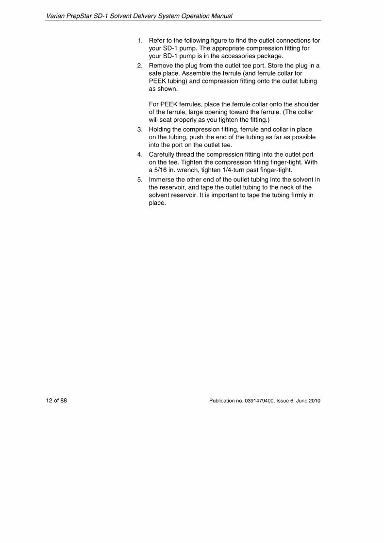
1. Refer to the following figure to find the outlet connections for your SD-1 pump. The appropriate compression fitting for your SD-1 pump is in the accessories package.
2. Remove the plug from the outlet tee port. Store the plug in a safe place. Assemble the ferrule (and ferrule collar for PEEK tubing) and compression fitting onto the outlet tubing as shown. For PEEK ferrules, place the ferrule collar onto the shoulder of the ferrule, large opening toward the ferrule. (The collar will seat properly as you tighten the fitting.)
3. Holding the compression fitting, ferrule and collar in place on the tubing, push the end of the tubing as far as possible into the port on the outlet tee.
4. Carefully thread the compression fitting into the outlet port on the tee. Tighten the compression fitting finger-tight. With a 5/16 in. wrench, tighten 1/4-turn past finger-tight.
5. Immerse the other end of the outlet tubing into the solvent in the reservoir, and tape the outlet tubing to the neck of the solvent reservoir. It is important to tape the tubing firmly in place.
Varian PrepStar SD-1 Solvent Delivery System Operation Manual
Publication no. 0391479400, Issue 6, June 2010 13 of 88
Figure 2. Outlet Connections
2.3.2.2 3.2 L Heads 1. Inlet and outlet plumbing use flared tubing compatible with
Fluoroware® Flaretek® fittings.
Caution These fittings, with the exception of the check valves, should only require hand tightening. Use of tools such as wrenches or pliers to tighten them may damage the fitting or cause the tubing to fail under pressure.
Varian PrepStar SD-1 Solvent Delivery System Operation Manual
14 of 88 Publication no. 0391479400, Issue 6, June 2010
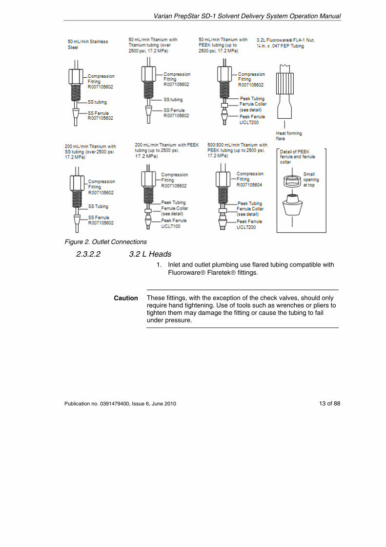
2. Remove and save the white shipping plug from the inlet valve and attach the inlet and outlet tube assemblies. See the following figure for suggested inlet and outlet configurations. The inlet tube to the solvent reservoir should be kept short, less than a few feet, since a long tube may result in large inlet pressure oscillations. It is recommended that tubing and reservoirs be flushed with air or filtered solvent and that only filtered solvent be used in the system.
Figure 3. Connections for 3.2 L pump heads
2.3.2.3 Priming the PrepStar SD-1 Note All heads are self-priming.
1. Tighten the outlet tee fitting 1/4-turn past finger-tight.
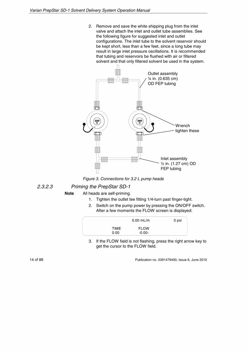
2. Switch on the pump power by pressing the ON/OFF switch. After a few moments the FLOW screen is displayed:
0.00 mL/m 0 psi
TIME0.00
FLOW-0.00-
3. If the FLOW field is not flashing, press the right arrow key to get the cursor to the FLOW field.
Wrench tighten these
Inlet assembly ½ in. (1.27 cm) OD FEP tubing
Outlet assembly ¼ in. (0.635 cm) OD FEP tubing
Varian PrepStar SD-1 Solvent Delivery System Operation Manual
Publication no. 0391479400, Issue 6, June 2010 15 of 88
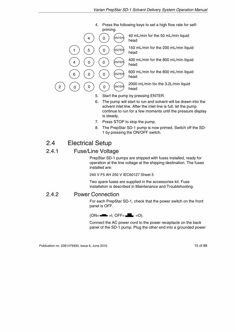
4. Press the following keys to set a high flow rate for self-priming.
40 mL/min for the 50 mL/min liquid head
150 mL/min for the 200 mL/min liquid head
400 mL/min for the 800 mL/min liquid head
600 mL/min for the 800 mL/min liquid head
2000 mL/min for the 3.2L/min liquid head
5. Start the pump by pressing ENTER.
6. The pump will start to run and solvent will be drawn into the solvent inlet line. After the inlet line is full, let the pump continue to run for a few moments until the pressure display is steady.
7. Press STOP to stop the pump.
8. The PrepStar SD-1 pump is now primed. Switch off the SD-1 by pressing the ON/OFF switch.
2.4 Electrical Setup 2.4.1 Fuse/Line Voltage
PrepStar SD-1 pumps are shipped with fuses installed, ready for operation at the line voltage at the shipping destination. The fuses installed are:
240 V F5 AH 250 V IEC60127 Sheet 5
Two spare fuses are supplied in the accessories kit. Fuse installation is described in Maintenance and Troublshooting.
2.4.2 Power Connection For each PrepStar SD-1, check that the power switch on the front panel is OFF. (ON= =I, OFF= =O).
Connect the AC power cord to the power receptacle on the back panel of the SD-1 pump. Plug the other end into a grounded power
00 2 0
00
0 0
0
0
6
4
1 5
4 ENTER
ENTER
ENTER
ENTER
ENTER
Varian PrepStar SD-1 Solvent Delivery System Operation Manual
16 of 88 Publication no. 0391479400, Issue 6, June 2010
socket or terminal strip, preferably in the same circuit as other components in the HPLC system.
Grounding is necessary to ensure operator safety and proper operation of the PrepStar SD-1.
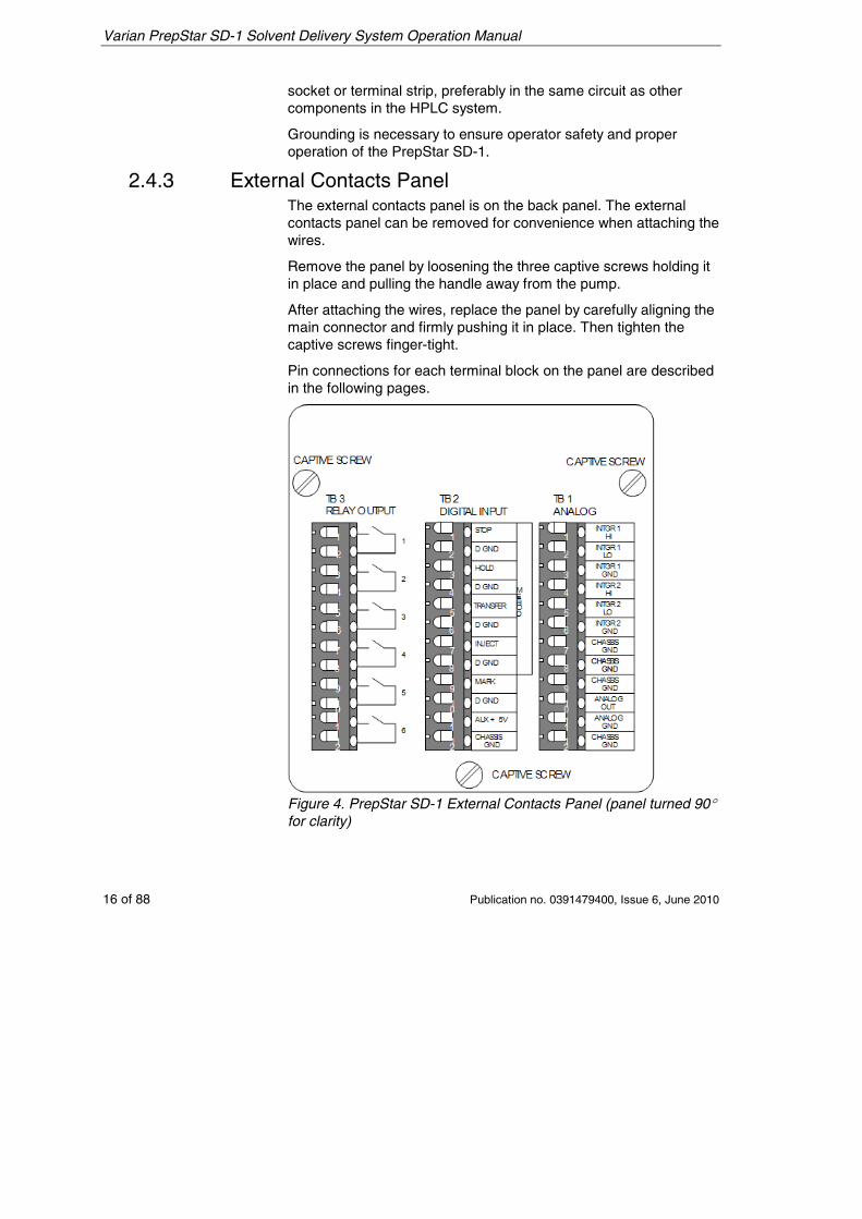
2.4.3 External Contacts Panel The external contacts panel is on the back panel. The external contacts panel can be removed for convenience when attaching the wires.
Remove the panel by loosening the three captive screws holding it in place and pulling the handle away from the pump.
After attaching the wires, replace the panel by carefully aligning the main connector and firmly pushing it in place. Then tighten the captive screws finger-tight.
Pin connections for each terminal block on the panel are described in the following pages.
Figure 4. PrepStar SD-1 External Contacts Panel (panel turned 90° for clarity)
Varian PrepStar SD-1 Solvent Delivery System Operation Manual
Publication no. 0391479400, Issue 6, June 2010 17 of 88
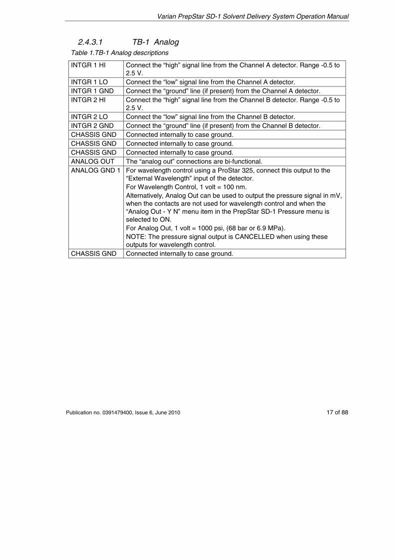
2.4.3.1 TB-1 Analog Table 1.TB-1 Analog descriptions
INTGR 1 HI Connect the “high” signal line from the Channel A detector. Range -0.5 to 2.5 V.
INTGR 1 LO Connect the “low” signal line from the Channel A detector. INTGR 1 GND Connect the “ground” line (if present) from the Channel A detector. INTGR 2 HI Connect the “high” signal line from the Channel B detector. Range -0.5 to
2.5 V. INTGR 2 LO Connect the “low” signal line from the Channel B detector. INTGR 2 GND Connect the “ground” line (if present) from the Channel B detector. CHASSIS GND Connected internally to case ground. CHASSIS GND Connected internally to case ground. CHASSIS GND Connected internally to case ground. ANALOG OUT The “analog out” connections are bi-functional. ANALOG GND 1 For wavelength control using a ProStar 325, connect this output to the
“External Wavelength” input of the detector. For Wavelength Control, 1 volt = 100 nm. Alternatively, Analog Out can be used to output the pressure signal in mV, when the contacts are not used for wavelength control and when the “Analog Out - Y N” menu item in the PrepStar SD-1 Pressure menu is selected to ON. For Analog Out, 1 volt = 1000 psi, (68 bar or 6.9 MPa). NOTE: The pressure signal output is CANCELLED when using these outputs for wavelength control.
CHASSIS GND Connected internally to case ground.
Varian PrepStar SD-1 Solvent Delivery System Operation Manual
18 of 88 Publication no. 0391479400, Issue 6, June 2010
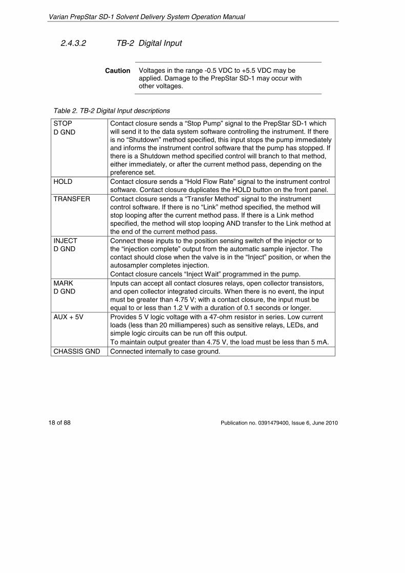
2.4.3.2 TB-2 Digital Input
Caution Voltages in the range -0.5 VDC to +5.5 VDC may be applied. Damage to the PrepStar SD-1 may occur with other voltages.
Table 2. TB-2 Digital Input descriptions
STOP D GND
Contact closure sends a “Stop Pump” signal to the PrepStar SD-1 which will send it to the data system software controlling the instrument. If there is no “Shutdown” method specified, this input stops the pump immediately and informs the instrument control software that the pump has stopped. If there is a Shutdown method specified control will branch to that method, either immediately, or after the current method pass, depending on the preference set.
HOLD Contact closure sends a “Hold Flow Rate” signal to the instrument control software. Contact closure duplicates the HOLD button on the front panel.
TRANSFER Contact closure sends a “Transfer Method” signal to the instrument control software. If there is no “Link” method specified, the method will stop looping after the current method pass. If there is a Link method specified, the method will stop looping AND transfer to the Link method at the end of the current method pass.
INJECT D GND
Connect these inputs to the position sensing switch of the injector or to the “injection complete” output from the automatic sample injector. The contact should close when the valve is in the “Inject” position, or when the autosampler completes injection. Contact closure cancels “Inject Wait” programmed in the pump.
MARK D GND
Inputs can accept all contact closures relays, open collector transistors, and open collector integrated circuits. When there is no event, the input must be greater than 4.75 V; with a contact closure, the input must be equal to or less than 1.2 V with a duration of 0.1 seconds or longer.
AUX + 5V Provides 5 V logic voltage with a 47-ohm resistor in series. Low current loads (less than 20 milliamperes) such as sensitive relays, LEDs, and simple logic circuits can be run off this output. To maintain output greater than 4.75 V, the load must be less than 5 mA.
CHASSIS GND Connected internally to case ground.
Varian PrepStar SD-1 Solvent Delivery System Operation Manual
Publication no. 0391479400, Issue 6, June 2010 19 of 88
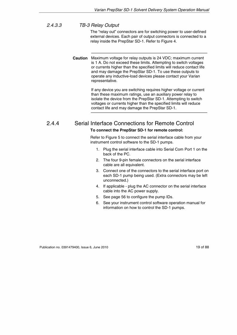
2.4.3.3 TB-3 Relay Output The “relay out” connectors are for switching power to user-defined external devices. Each pair of output connectors is connected to a relay inside the PrepStar SD-1. Refer to Figure 4.
Caution Maximum voltage for relay outputs is 24 VDC; maximum current is 1 A. Do not exceed these limits. Attempting to switch voltages or currents higher than the specified limits will reduce contact life and may damage the PrepStar SD-1. To use these outputs to operate any inductive-load devices please contact your Varian representative. If any device you are switching requires higher voltage or current than these maximum ratings, use an auxiliary power relay to isolate the device from the PrepStar SD-1. Attempting to switch voltages or currents higher than the specified limits will reduce contact life and may damage the PrepStar SD-1.
2.4.4 Serial Interface Connections for Remote Control To connect the PrepStar SD-1 for remote control:
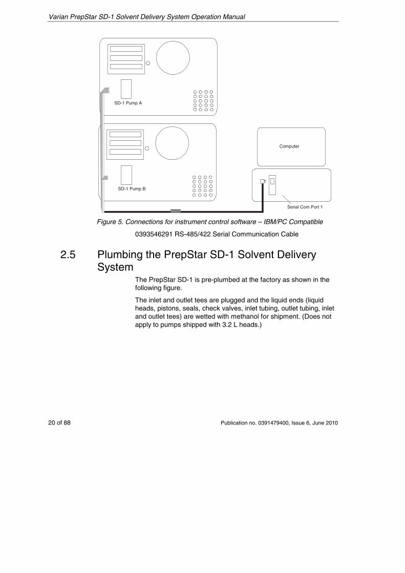
Refer to Figure 5 to connect the serial interface cable from your instrument control software to the SD-1 pumps.
1. Plug the serial interface cable into Serial Com Port 1 on the back of the PC.
2. The four 9-pin female connectors on the serial interface cable are all equivalent.
3. Connect one of the connectors to the serial interface port on each SD-1 pump being used. (Extra connectors may be left unconnected.)
4. If applicable - plug the AC connector on the serial interface cable into the AC power supply.
5. See page 56 to configure the pump IDs.
6. See your instrument control software operation manual for information on how to control the SD-1 pumps.
Varian PrepStar SD-1 Solvent Delivery System Operation Manual
20 of 88 Publication no. 0391479400, Issue 6, June 2010
SD-1 Pump B
Computer
Serial Com Port 1
SD-1 Pump A
Figure 5. Connections for instrument control software – IBM/PC Compatible
0393546291 RS-485/422 Serial Communication Cable
2.5 Plumbing the PrepStar SD-1 Solvent Delivery System
The PrepStar SD-1 is pre-plumbed at the factory as shown in the following figure.
The inlet and outlet tees are plugged and the liquid ends (liquid heads, pistons, seals, check valves, inlet tubing, outlet tubing, inlet and outlet tees) are wetted with methanol for shipment. (Does not apply to pumps shipped with 3.2 L heads.)
Varian PrepStar SD-1 Solvent Delivery System Operation Manual
Publication no. 0391479400, Issue 6, June 2010 21 of 88
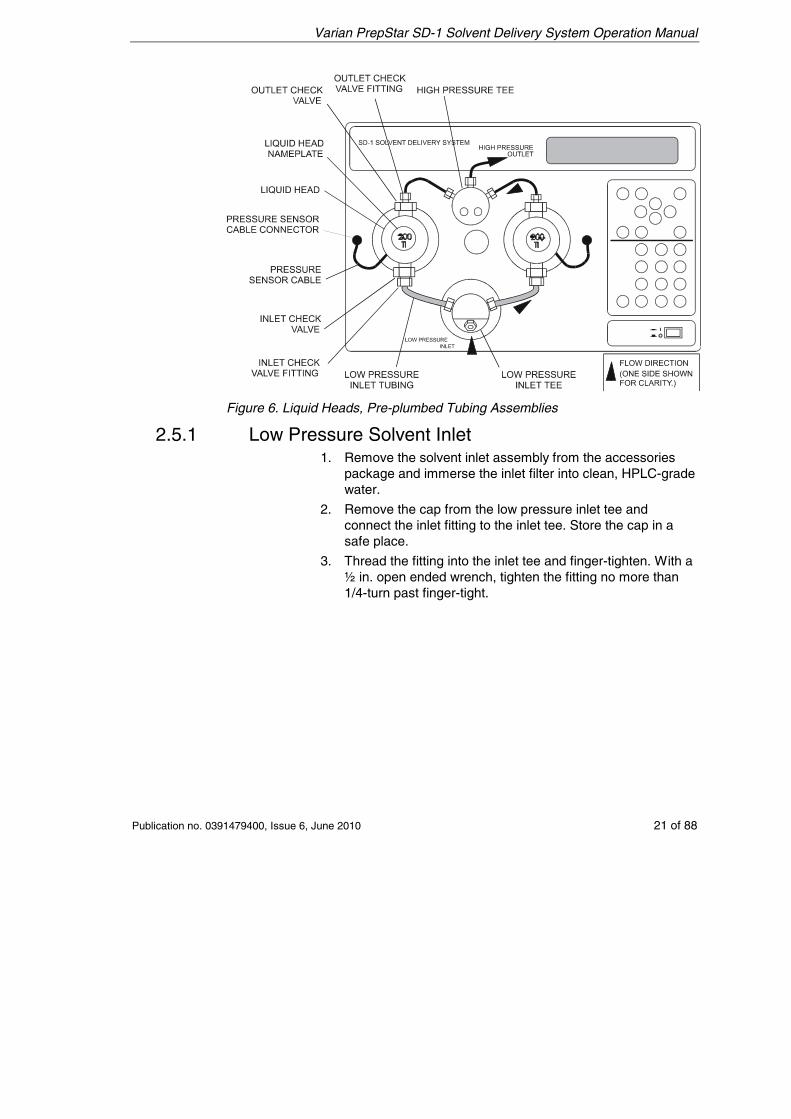
Figure 6. Liquid Heads, Pre-plumbed Tubing Assemblies
2.5.1 Low Pressure Solvent Inlet 1. Remove the solvent inlet assembly from the accessories
package and immerse the inlet filter into clean, HPLC-grade water.
2. Remove the cap from the low pressure inlet tee and connect the inlet fitting to the inlet tee. Store the cap in a safe place.
3. Thread the fitting into the inlet tee and finger-tighten. With a ½ in. open ended wrench, tighten the fitting no more than 1/4-turn past finger-tight.
Varian PrepStar SD-1 Solvent Delivery System Operation Manual
22 of 88 Publication no. 0391479400, Issue 6, June 2010
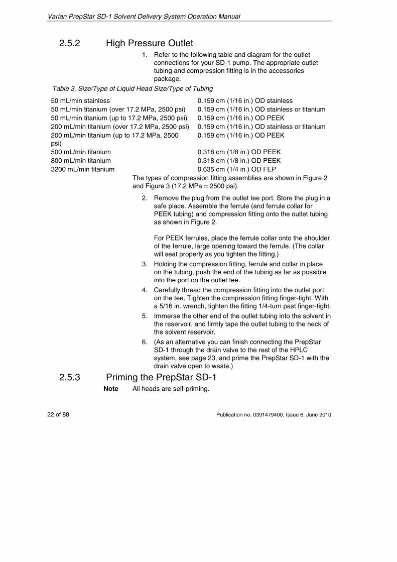
2.5.2 High Pressure Outlet 1. Refer to the following table and diagram for the outlet
connections for your SD-1 pump. The appropriate outlet tubing and compression fitting is in the accessories package.
Table 3. Size/Type of Liquid Head Size/Type of Tubing
50 mL/min stainless 0.159 cm (1/16 in.) OD stainless 50 mL/min titanium (over 17.2 MPa, 2500 psi) 0.159 cm (1/16 in.) OD stainless or titanium 50 mL/min titanium (up to 17.2 MPa, 2500 psi) 0.159 cm (1/16 in.) OD PEEK 200 mL/min titanium (over 17.2 MPa, 2500 psi) 0.159 cm (1/16 in.) OD stainless or titanium 200 mL/min titanium (up to 17.2 MPa, 2500 psi)
0.159 cm (1/16 in.) OD PEEK
500 mL/min titanium 0.318 cm (1/8 in.) OD PEEK 800 mL/min titanium 0.318 cm (1/8 in.) OD PEEK 3200 mL/min titanium 0.635 cm (1/4 in.) OD FEP
The types of compression fitting assemblies are shown in Figure 2 and Figure 3 (17.2 MPa = 2500 psi).
2. Remove the plug from the outlet tee port. Store the plug in a safe place. Assemble the ferrule (and ferrule collar for PEEK tubing) and compression fitting onto the outlet tubing as shown in Figure 2. For PEEK ferrules, place the ferrule collar onto the shoulder of the ferrule, large opening toward the ferrule. (The collar will seat properly as you tighten the fitting.)
3. Holding the compression fitting, ferrule and collar in place on the tubing, push the end of the tubing as far as possible into the port on the outlet tee.
4. Carefully thread the compression fitting into the outlet port on the tee. Tighten the compression fitting finger-tight. With a 5/16 in. wrench, tighten the fitting 1/4-turn past finger-tight.
5. Immerse the other end of the outlet tubing into the solvent in the reservoir, and firmly tape the outlet tubing to the neck of the solvent reservoir.
6. (As an alternative you can finish connecting the PrepStar SD-1 through the drain valve to the rest of the HPLC system, see page 23, and prime the PrepStar SD-1 with the drain valve open to waste.)
2.5.3 Priming the PrepStar SD-1 Note All heads are self-priming.
Varian PrepStar SD-1 Solvent Delivery System Operation Manual
Publication no. 0391479400, Issue 6, June 2010 23 of 88
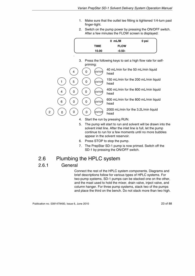
1. Make sure that the outlet tee fitting is tightened 1/4-turn past finger-tight.
2. Switch on the pump power by pressing the ON/OFF switch. After a few minutes the FLOW screen is displayed:
0 mL/M 0 psi
TIME FLOW
10.00 -0.50-
3. Press the following keys to set a high flow rate for self-priming:
40 mL/min for the 50 mL/min liquid head
150 mL/min for the 200 mL/min liquid head
400 mL/min for the 800 mL/min liquid head
600 mL/min for the 800 mL/min liquid head
2000 mL/min for the 3.2L/min liquid head
4. Start the run by pressing RUN.
5. The pump will start to run and solvent will be drawn into the solvent inlet line. After the inlet line is full, let the pump continue to run for a few moments until no more bubbles appear in the solvent reservoir.
6. Press STOP to stop the pump.
7. The PrepStar SD-1 pump is now primed. Switch off the SD-1 by pressing the ON/OFF switch.
2.6 Plumbing the HPLC system 2.6.1 General
Connect the rest of the HPLC system components. Diagrams and brief descriptions follow for various types of HPLC systems. For two-pump systems, SD-1 pumps can be stacked one on the other, and the mast used to hold the mixer, drain valve, inject valve, and column hanger. For three pump systems, stack two of the pumps and place the third on the bench. Do not stack more than two high.
00 2 0
00
0 0
0
0
6
4
1 5
4 ENTER
ENTER
ENTER
ENTER
ENTER
Varian PrepStar SD-1 Solvent Delivery System Operation Manual
24 of 88 Publication no. 0391479400, Issue 6, June 2010
When stacking pumps, especially at high flow rates, place a rubber mat between the pumps to reduce vibration and movement.
When attaching new pieces of tubing to your HPLC system, leave the column inlet fitting disconnected until you have flushed the tubing ahead of the column, as described in Initial Operation on page 46. This will prevent impurities or particulates from the new tubing (such as dust, cutting oils, metallic particles, etc.) from clogging the column inlet frit or damaging the column.
New systems supplied from the factory have been set up and operated, so the tubing has already been flushed when you receive your system. In this case it is not necessary to disconnect the fitting to flush the system; opening the system drain valve and diverting the flow to waste is sufficient.
2.6.2 Isocratic HPLC Systems
PrepStar SD-1
Injector Valve
DetectorFromSolventReservoir
Drain Valve
Column
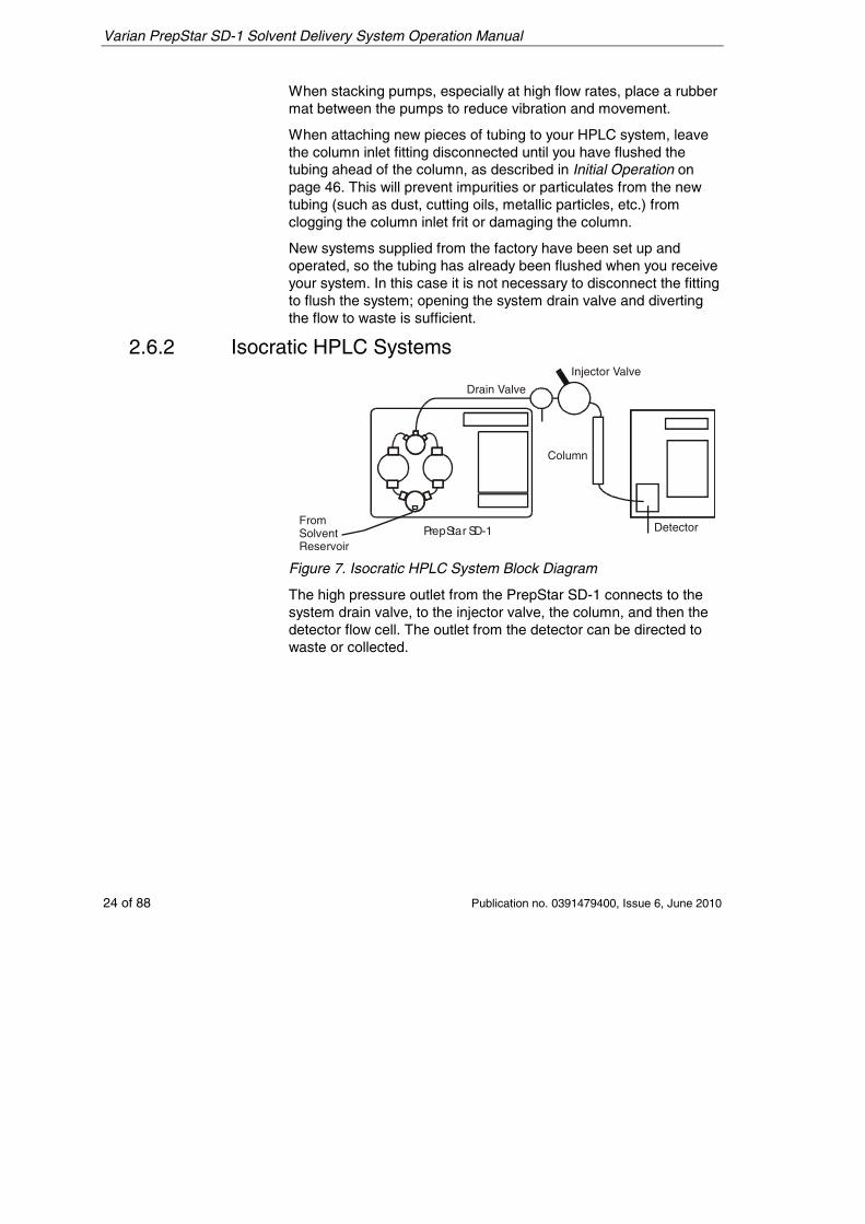
Figure 7. Isocratic HPLC System Block Diagram
The high pressure outlet from the PrepStar SD-1 connects to the system drain valve, to the injector valve, the column, and then the detector flow cell. The outlet from the detector can be directed to waste or collected.
Varian PrepStar SD-1 Solvent Delivery System Operation Manual
Publication no. 0391479400, Issue 6, June 2010 25 of 88
2.6.3 Gradient HPLC Systems
FromSolventReservoir A
FromSolventReservoir B
PrepStar SD-1Pump-A
High PressureMixer
Injector Valve
Drain Valve
PrepStar SD-1 Pump-B Detector
Colum
n
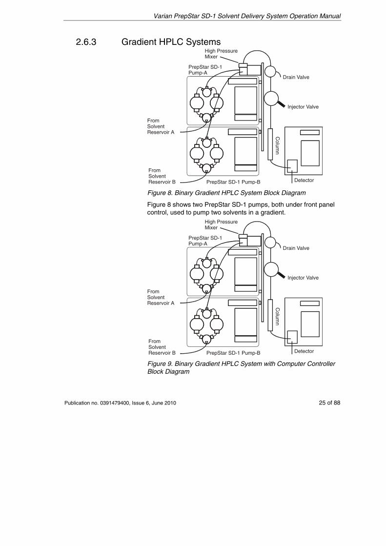
Figure 8. Binary Gradient HPLC System Block Diagram
Figure 8 shows two PrepStar SD-1 pumps, both under front panel control, used to pump two solvents in a gradient.
FromSolventReservoir A
FromSolventReservoir B
PrepStar SD-1Pump-A
High PressureMixer
Injector Valve
Drain Valve
PrepStar SD-1 Pump-B Detector
Colum
n
Figure 9. Binary Gradient HPLC System with Computer Controller Block Diagram
Varian PrepStar SD-1 Solvent Delivery System Operation Manual
26 of 88 Publication no. 0391479400, Issue 6, June 2010
Figure 9 shows a binary gradient HPLC system controlled by applicable instrument control software on a PC. The software controls the flow rates for both PrepStar SD-1 pumps. Electrical connections between the pumps and the computer are shown earlier in this section in Figure 5. Refer to the manual for your instrument control software for information on programming the method.
Plumbing is the same for both these systems. The high pressure outlets from both PrepStar SD-1 pumps are connected to a high pressure mixer, to ensure that both solvents are mixed thoroughly. The system drain valve is plumbed after the mixer. The injector valve is plumbed after the drain valve, then the column, then the detector flow cell. The outlet from the detector can be directed to waste or collected.
Varian PrepStar SD-1 Solvent Delivery System Operation Manual
Publication no. 0391479400, Issue 6, June 2010 27 of 88
2.6.4 AutoPrep HPLC System
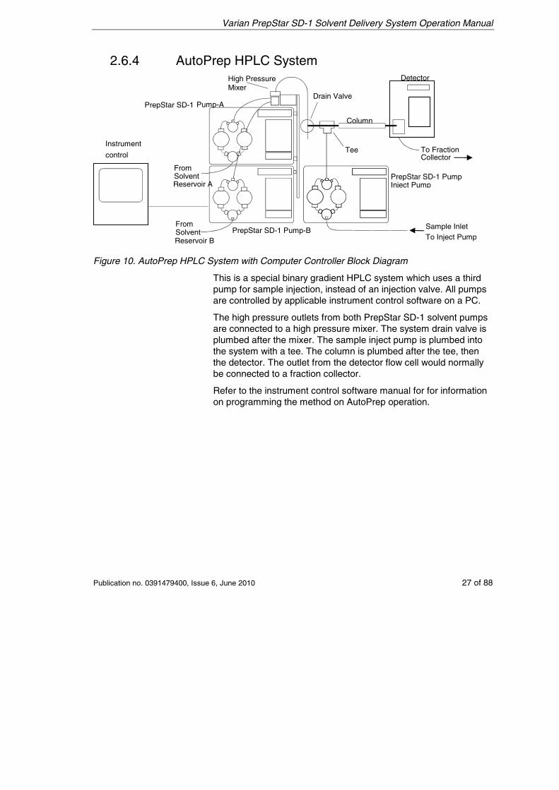
Figure 10. AutoPrep HPLC System with Computer Controller Block Diagram
This is a special binary gradient HPLC system which uses a third pump for sample injection, instead of an injection valve. All pumps are controlled by applicable instrument control software on a PC.
The high pressure outlets from both PrepStar SD-1 solvent pumps are connected to a high pressure mixer. The system drain valve is plumbed after the mixer. The sample inject pump is plumbed into the system with a tee. The column is plumbed after the tee, then the detector. The outlet from the detector flow cell would normally be connected to a fraction collector.
Refer to the instrument control software manual for for information on programming the method on AutoPrep operation.
Mixer
Inject Pump
Collector
FromSolvent Reservoir B
Instrument
control
PrepStar SD-1 Pump-A
FromSolvent Reservoir A
High Pressure
Drain Valve
PrepStar SD-1 Pump-B
Column
To Fraction
PrepStar SD-1 Pump
Sample Inlet To Inject Pump
Tee
Detector
Varian PrepStar SD-1 Solvent Delivery System Operation Manual
28 of 88 Publication no. 0391479400, Issue 6, June 2010
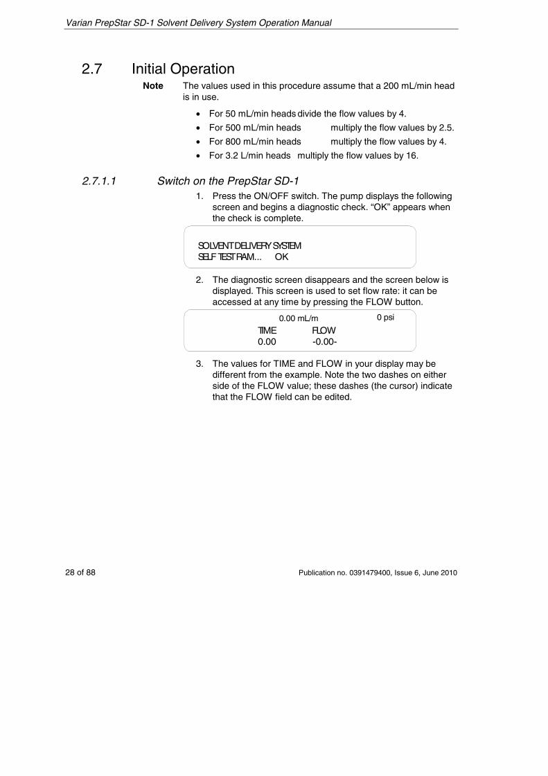
2.7 Initial Operation Note The values used in this procedure assume that a 200 mL/min head
is in use.
• For 50 mL/min heads divide the flow values by 4.
• For 500 mL/min heads multiply the flow values by 2.5.
• For 800 mL/min heads multiply the flow values by 4.
• For 3.2 L/min heads multiply the flow values by 16.
2.7.1.1 Switch on the PrepStar SD-1 1. Press the ON/OFF switch. The pump displays the following
screen and begins a diagnostic check. “OK” appears when the check is complete.
SOLVENTDELIVERYSYSTEMSELFTESTRAM... OK
2. The diagnostic screen disappears and the screen below is displayed. This screen is used to set flow rate: it can be accessed at any time by pressing the FLOW button.
0.00 mL/m 0 psi
TIME FLOW0.00 -0.00-
3. The values for TIME and FLOW in your display may be different from the example. Note the two dashes on either side of the FLOW value; these dashes (the cursor) indicate that the FLOW field can be edited.
Varian PrepStar SD-1 Solvent Delivery System Operation Manual
Publication no. 0391479400, Issue 6, June 2010 29 of 88
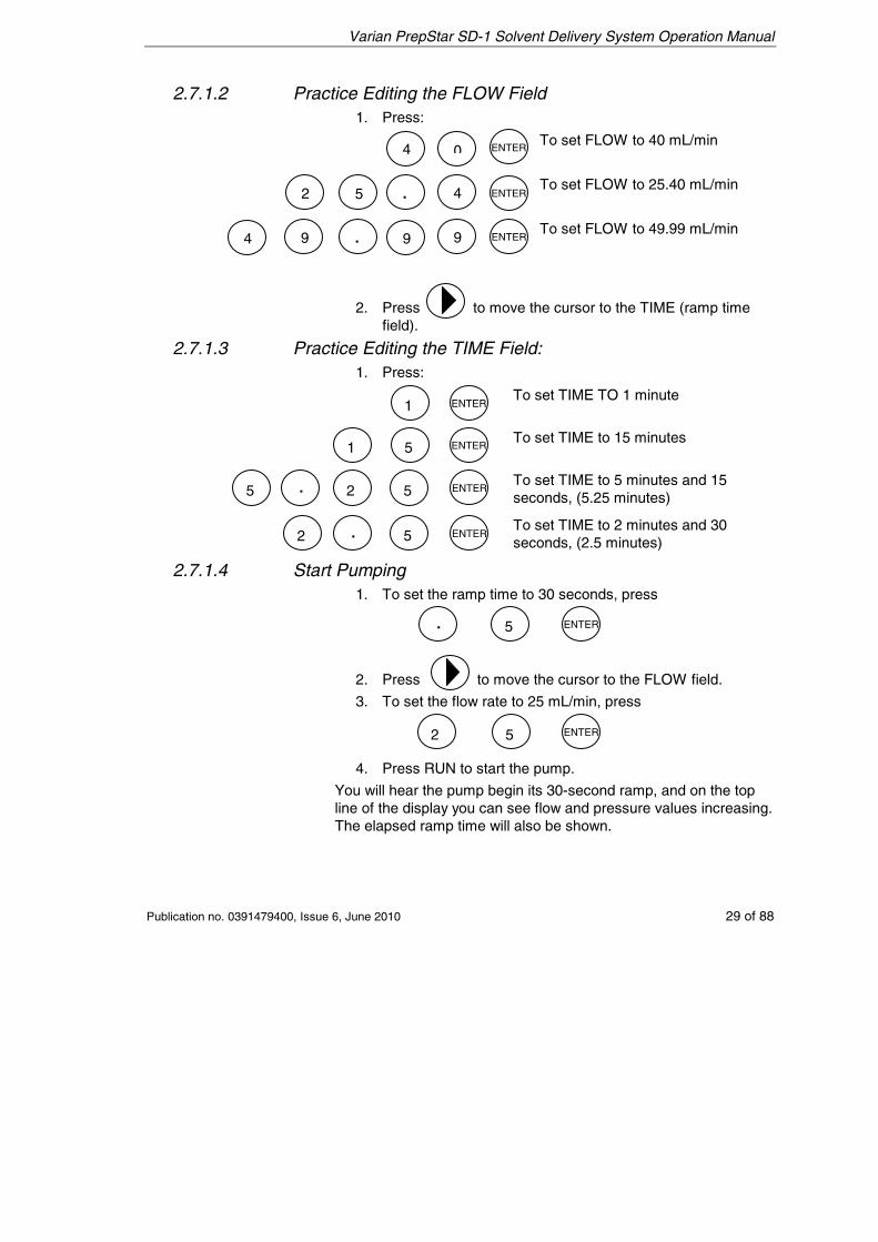
2.7.1.2 Practice Editing the FLOW Field 1. Press:
To set FLOW to 40 mL/min
To set FLOW to 25.40 mL/min
To set FLOW to 49.99 mL/min
2. Press to move the cursor to the TIME (ramp time
field).
2.7.1.3 Practice Editing the TIME Field: 1. Press:
To set TIME TO 1 minute
To set TIME to 15 minutes
To set TIME to 5 minutes and 15 seconds, (5.25 minutes)
To set TIME to 2 minutes and 30 seconds, (2.5 minutes)
2.7.1.4 Start Pumping 1. To set the ramp time to 30 seconds, press
2. Press to move the cursor to the FLOW field.
3. To set the flow rate to 25 mL/min, press
4. Press RUN to start the pump.
You will hear the pump begin its 30-second ramp, and on the top line of the display you can see flow and pressure values increasing. The elapsed ramp time will also be shown.
04
4
4
2 5 .
. 9 9 9
1
1 5
5 5
5
5
5
.
.
.
2
2
2
ENTER
ENTER
ENTER
ENTER
ENTER
ENTER
ENTER
ENTER
ENTER
Varian PrepStar SD-1 Solvent Delivery System Operation Manual
30 of 88 Publication no. 0391479400, Issue 6, June 2010
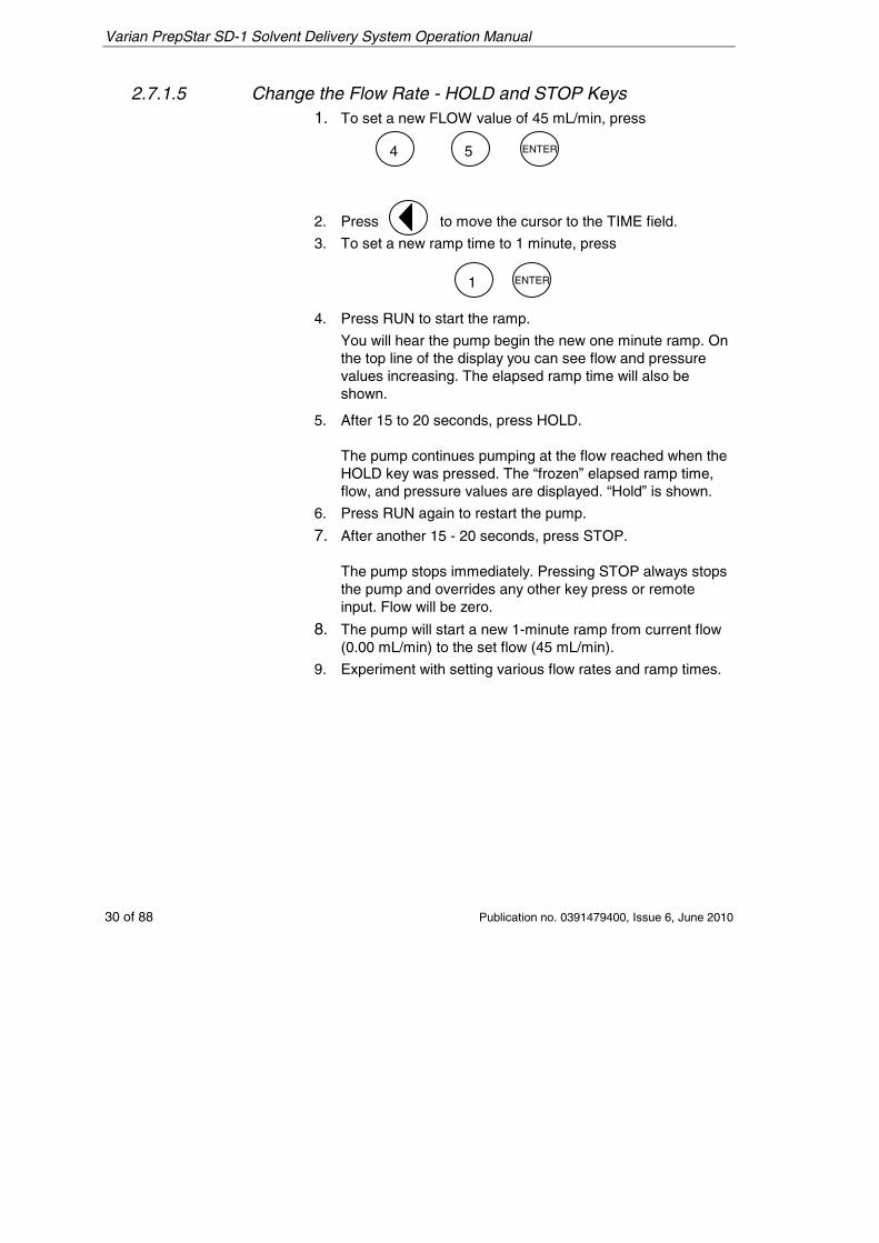
2.7.1.5 Change the Flow Rate - HOLD and STOP Keys 1. To set a new FLOW value of 45 mL/min, press
2. Press to move the cursor to the TIME field.
3. To set a new ramp time to 1 minute, press
4. Press RUN to start the ramp.
You will hear the pump begin the new one minute ramp. On the top line of the display you can see flow and pressure values increasing. The elapsed ramp time will also be shown.
5. After 15 to 20 seconds, press HOLD. The pump continues pumping at the flow reached when the HOLD key was pressed. The “frozen” elapsed ramp time, flow, and pressure values are displayed. “Hold” is shown.
6. Press RUN again to restart the pump.
7. After another 15 - 20 seconds, press STOP. The pump stops immediately. Pressing STOP always stops the pump and overrides any other key press or remote input. Flow will be zero.
8. The pump will start a new 1-minute ramp from current flow (0.00 mL/min) to the set flow (45 mL/min).
9. Experiment with setting various flow rates and ramp times.
54 ENTER
1 ENTER
Varian PrepStar SD-1 Solvent Delivery System Operation Manual
Publication no. 0391479400, Issue 6, June 2010 31 of 88
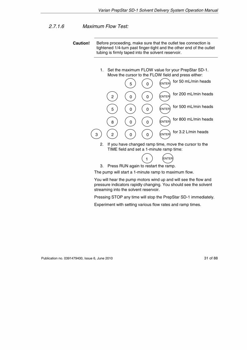
2.7.1.6 Maximum Flow Test:
Caution! Before proceeding, make sure that the outlet tee connection is tightened 1/4-turn past finger-tight and the other end of the outlet tubing is firmly taped into the solvent reservoir.
1. Set the maximum FLOW value for your PrepStar SD-1. Move the cursor to the FLOW field and press either:
for 50 mL/min heads
for 200 mL/min heads
for 500 mL/min heads
for 800 mL/min heads
for 3.2 L/min heads
2. If you have changed ramp time, move the cursor to the TIME field and set a 1-minute ramp time:
3. Press RUN again to restart the ramp.
The pump will start a 1-minute ramp to maximum flow.
You will hear the pump motors wind up and will see the flow and pressure indicators rapidly changing. You should see the solvent streaming into the solvent reservoir.
Pressing STOP any time will stop the PrepStar SD-1 immediately.
Experiment with setting various flow rates and ramp times.
5 0
0
0
0
0
0
0
0
0
5
2
8
23
ENTER
ENTER
ENTER
ENTER
ENTER
1 ENTER
Varian PrepStar SD-1 Solvent Delivery System Operation Manual
32 of 88 Publication no. 0391479400, Issue 6, June 2010
This page is intentionally left blank.
Varian PrepStar SD-1 Solvent Delivery System Operation Manual
Publication no. 0391479400, Issue 6, June 2010 33 of 88
3. Instrument Description
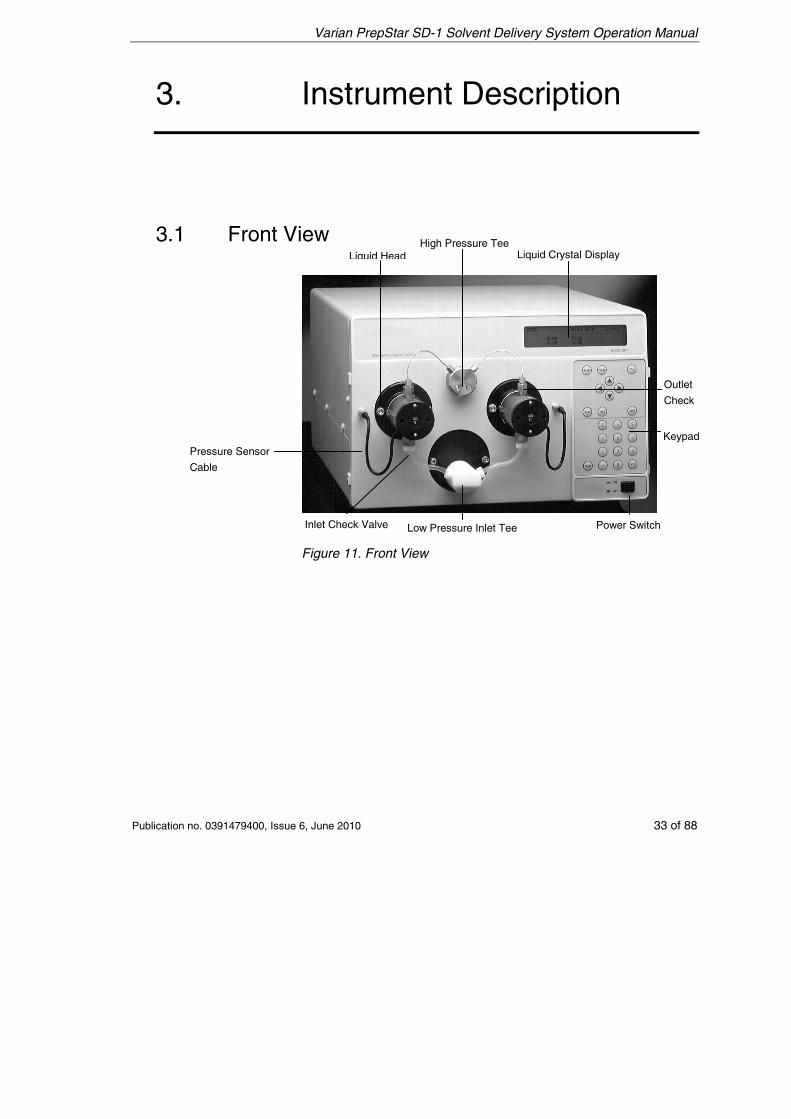
3.1 Front View
Figure 11. Front View
Low Pressure Inlet Tee Power Switch Inlet Check Valve
Pressure Sensor
Cable
Outlet
Check
Liquid Crystal Display Liquid HeadHigh Pressure Tee
Keypad
Varian PrepStar SD-1 Solvent Delivery System Operation Manual
34 of 88 Publication no. 0391479400, Issue 6, June 2010
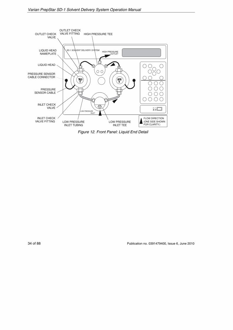
SD-1 SOLVENT DELIVERY SYSTEM
HIGH PRESSURE TEEOUTLET CHECKVALVE FITTINGOUTLET CHECK
VALVE
LIQUID HEADNAMEPLATE
LIQUID HEAD
PRESSURE SENSORCABLE CONNECTOR
PRESSURESENSOR CABLE
INLET CHECKVALVE
INLET CHECKVALVE FITTING LOW PRESSURE
INLET TUBINGLOW PRESSURE
INLET TEE
LOW PRESSUREINLET
HIGH PRESSUREOUTLET
FLOW DIRECTION (ONE SIDE SHOWNFOR CLARITY.)
Figure 12. Front Panel: Liquid End Detail
Varian PrepStar SD-1 Solvent Delivery System Operation Manual
Publication no. 0391479400, Issue 6, June 2010 35 of 88
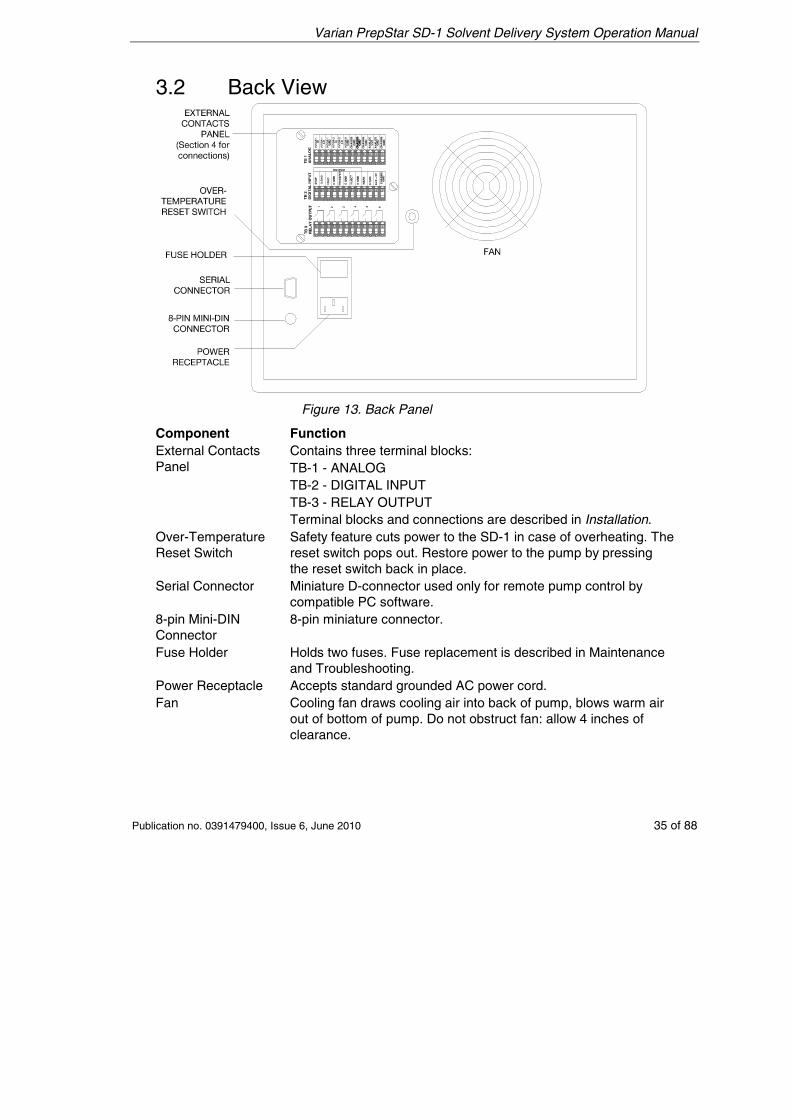
3.2 Back View
Figure 13. Back Panel
Component Function External Contacts Panel
Contains three terminal blocks: TB-1 - ANALOG TB-2 - DIGITAL INPUT TB-3 - RELAY OUTPUT Terminal blocks and connections are described in Installation.
Over-Temperature Reset Switch
Safety feature cuts power to the SD-1 in case of overheating. The reset switch pops out. Restore power to the pump by pressing the reset switch back in place.
Serial Connector Miniature D-connector used only for remote pump control by compatible PC software.
8-pin Mini-DIN Connector
8-pin miniature connector.
Fuse Holder Holds two fuses. Fuse replacement is described in Maintenance and Troubleshooting.
Power Receptacle Accepts standard grounded AC power cord. Fan Cooling fan draws cooling air into back of pump, blows warm air
out of bottom of pump. Do not obstruct fan: allow 4 inches of clearance.
Varian PrepStar SD-1 Solvent Delivery System Operation Manual
36 of 88 Publication no. 0391479400, Issue 6, June 2010
3.3 Keypad
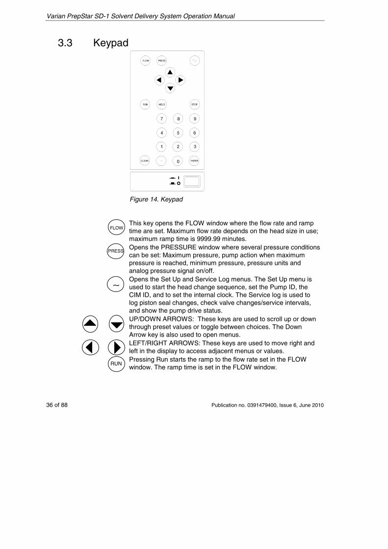
Figure 14. Keypad
This key opens the FLOW window where the flow rate and ramp time are set. Maximum flow rate depends on the head size in use; maximum ramp time is 9999.99 minutes.
Opens the PRESSURE window where several pressure conditions can be set: Maximum pressure, pump action when maximum pressure is reached, minimum pressure, pressure units and analog pressure signal on/off.
Opens the Set Up and Service Log menus. The Set Up menu is used to start the head change sequence, set the Pump ID, the CIM ID, and to set the internal clock. The Service log is used to log piston seal changes, check valve changes/service intervals, and show the pump drive status.
UP/DOWN ARROWS: These keys are used to scroll up or down through preset values or toggle between choices. The Down Arrow key is also used to open menus.
LEFT/RIGHT ARROWS: These keys are used to move right and left in the display to access adjacent menus or values.
Pressing Run starts the ramp to the flow rate set in the FLOW window. The ramp time is set in the FLOW window.
∼
FLOW
PRESS
RUN
Varian PrepStar SD-1 Solvent Delivery System Operation Manual
Publication no. 0391479400, Issue 6, June 2010 37 of 88
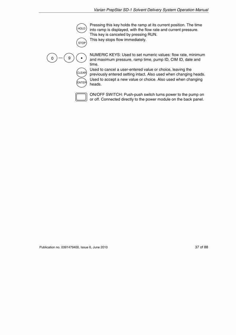
Pressing this key holds the ramp at its current position. The time into ramp is displayed, with the flow rate and current pressure. This key is canceled by pressing RUN.
This key stops flow immediately.
NUMERIC KEYS: Used to set numeric values: flow rate, minimum and maximum pressure, ramp time, pump ID, CIM ID, date and time.
Used to cancel a user-entered value or choice, leaving the previously entered setting intact. Also used when changing heads.
Used to accept a new value or choice. Also used when changing heads.
ON/OFF SWITCH: Push-push switch turns power to the pump on or off. Connected directly to the power module on the back panel.
0 9 •
HOLD
STOP
CLEAR
ENTER
Varian PrepStar SD-1 Solvent Delivery System Operation Manual
38 of 88 Publication no. 0391479400, Issue 6, June 2010
3.4 SD-1 Displays 3.4.1 Cursors
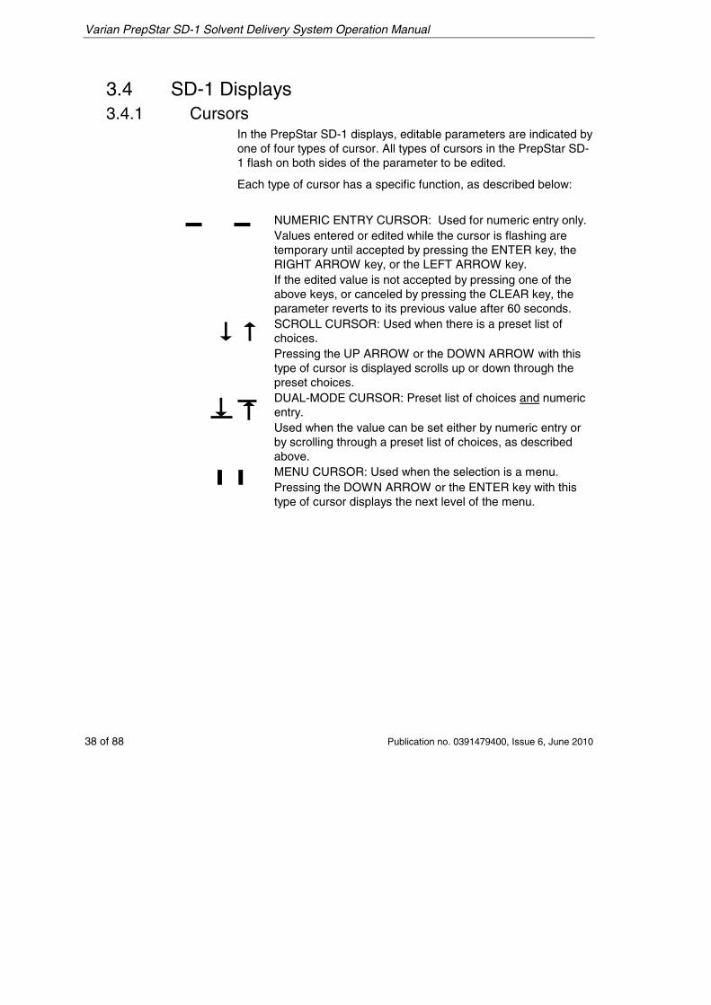
In the PrepStar SD-1 displays, editable parameters are indicated by one of four types of cursor. All types of cursors in the PrepStar SD-1 flash on both sides of the parameter to be edited.
Each type of cursor has a specific function, as described below:
NUMERIC ENTRY CURSOR: Used for numeric entry only. Values entered or edited while the cursor is flashing are temporary until accepted by pressing the ENTER key, the RIGHT ARROW key, or the LEFT ARROW key.
If the edited value is not accepted by pressing one of the above keys, or canceled by pressing the CLEAR key, the parameter reverts to its previous value after 60 seconds.
SCROLL CURSOR: Used when there is a preset list of choices. Pressing the UP ARROW or the DOWN ARROW with this type of cursor is displayed scrolls up or down through the preset choices.
DUAL-MODE CURSOR: Preset list of choices and numeric entry. Used when the value can be set either by numeric entry or by scrolling through a preset list of choices, as described above.
❙ ❙ MENU CURSOR: Used when the selection is a menu. Pressing the DOWN ARROW or the ENTER key with this type of cursor displays the next level of the menu.
Varian PrepStar SD-1 Solvent Delivery System Operation Manual
Publication no. 0391479400, Issue 6, June 2010 39 of 88
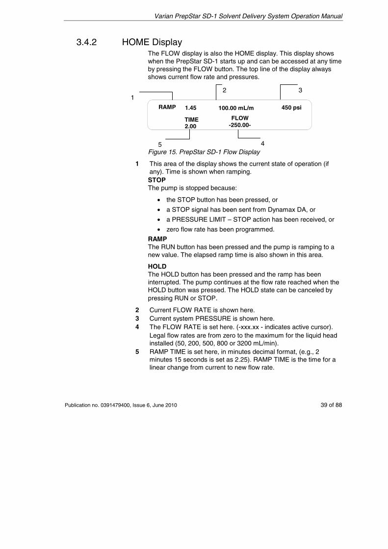
3.4.2 HOME Display The FLOW display is also the HOME display. This display shows when the PrepStar SD-1 starts up and can be accessed at any time by pressing the FLOW button. The top line of the display always shows current flow rate and pressures.
100.00 mL/m 450 psiRAMP
FLOW-250.00-
TIME
1.45
2.00
Figure 15. PrepStar SD-1 Flow Display
1 This area of the display shows the current state of operation (if any). Time is shown when ramping. STOP The pump is stopped because:
• the STOP button has been pressed, or
• a STOP signal has been sent from Dynamax DA, or
• a PRESSURE LIMIT – STOP action has been received, or
• zero flow rate has been programmed.
RAMP The RUN button has been pressed and the pump is ramping to a new value. The elapsed ramp time is also shown in this area.
HOLD The HOLD button has been pressed and the ramp has been interrupted. The pump continues at the flow rate reached when the HOLD button was pressed. The HOLD state can be canceled by pressing RUN or STOP.
2 Current FLOW RATE is shown here. 3 Current system PRESSURE is shown here. 4 The FLOW RATE is set here. (-xxx.xx - indicates active cursor).
Legal flow rates are from zero to the maximum for the liquid head installed (50, 200, 500, 800 or 3200 mL/min).
5 RAMP TIME is set here, in minutes decimal format, (e.g., 2 minutes 15 seconds is set as 2.25). RAMP TIME is the time for a linear change from current to new flow rate.
3 2 1
5 4
Varian PrepStar SD-1 Solvent Delivery System Operation Manual
40 of 88 Publication no. 0391479400, Issue 6, June 2010
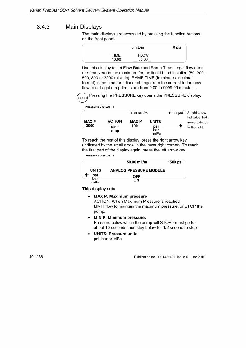
3.4.3 Main Displays The main displays are accessed by pressing the function buttons on the front panel.
0 mL/m 0 psi
TIME10.00
FLOW50.00
Use this display to set Flow Rate and Ramp Time. Legal flow rates are from zero to the maximum for the liquid head installed (50, 200, 500, 800 or 3200 mL/min). RAMP TIME (in minutes. decimal format) is the time for a linear change from the current to the new flow rate. Legal ramp times are from 0.00 to 9999.99 minutes.
Pressing the PRESSURE key opens the PRESSURE display.
MAX P3000
MAX P100
ACTION
limitstop
UNITSpsibarmPa
PRESSURE DISPLAY 1
50.00 mL/m 1500 psi
RIGHT ARROW
EXTENDS TO RIGHT
To reach the rest of this display, press the right arrow key (indicated by the small arrow in the lower right corner). To reach the first part of the display again, press the left arrow key.
ANALOG PRESSURE MODULE
OFFON
UNITSpsibarmPa
PRESSURE DISPLAY 2
50.00 mL/m 1500 psi
This display sets:
• MAX P: Maximum pressure ACTION: When Maximum Pressure is reached LIMIT flow to maintain the maximum pressure, or STOP the pump.
• MIN P: Minimum pressure. Pressure below which the pump will STOP - must go for about 10 seconds then stay below for 1/2 second to stop.
• UNITS: Pressure units psi, bar or MPa
A right arrow
indicates that
menu extends
to the right.
PRESS
Varian PrepStar SD-1 Solvent Delivery System Operation Manual
Publication no. 0391479400, Issue 6, June 2010 41 of 88
• ANALOG PRESSURE MONITOR: ON or OFF. Sends an analog signal [1000 psi/volt] to an external pressure monitor or chart recorder, if the instrument control software is not controlling the detector wavelength through the ANALOG OUT contacts on the SD-1.
When controlling detector wavelength, the instrument control software may override this control. The SD-1 may need to be switched OFF and ON to release the override.
Refer to page 17 for TB-1 Analog description.
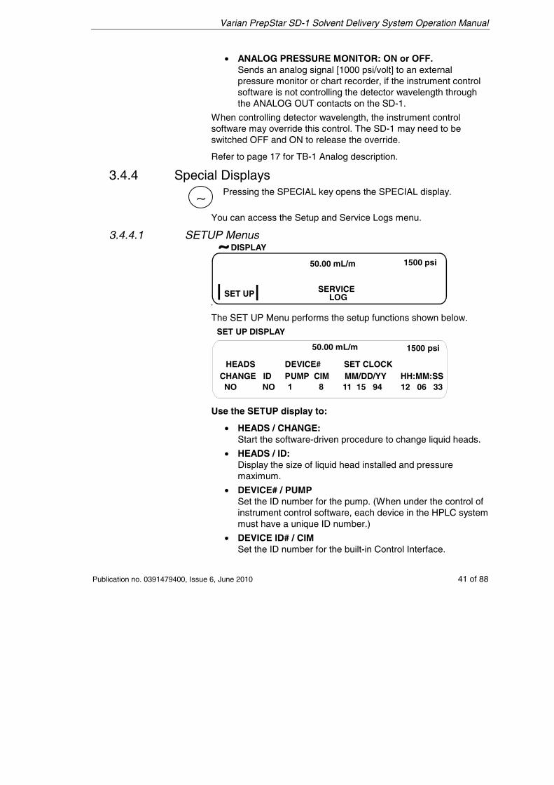
3.4.4 Special Displays Pressing the SPECIAL key opens the SPECIAL display.
You can access the Setup and Service Logs menu.
3.4.4.1 SETUP Menus
50.00 mL/m 1500 psi
SET UP
DISPLAY
SERVICELOG
The SET UP Menu performs the setup functions shown below.
SET UP DISPLAY
50.00 mL/m 1500 psi
HEADSCHANGE ID
DEVICE#PUMP CIM
SET CLOCKMM/DD/YY HH:MM:SS
NO NO 11 15 94 12 06 33
Use the SETUP display to:
• HEADS / CHANGE: Start the software-driven procedure to change liquid heads.
• HEADS / ID: Display the size of liquid head installed and pressure maximum.
• DEVICE# / PUMP Set the ID number for the pump. (When under the control of instrument control software, each device in the HPLC system must have a unique ID number.)
• DEVICE ID# / CIM Set the ID number for the built-in Control Interface.
∼
Varian PrepStar SD-1 Solvent Delivery System Operation Manual
42 of 88 Publication no. 0391479400, Issue 6, June 2010
• SET CLOCK / MM/DD/YY Set month/day/year with numeric keys
• SET CLOCK / HH:MM:SS Set hour/minute/second with numeric keys
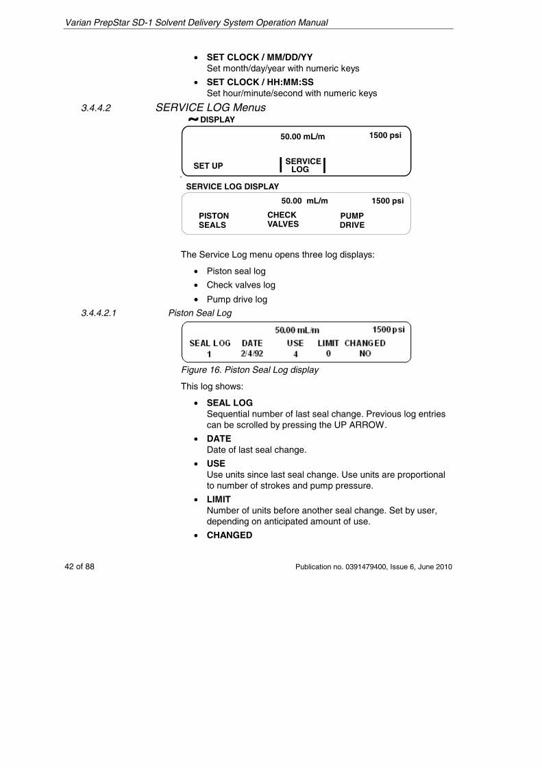
3.4.4.2 SERVICE LOG Menus
50.00 mL/m 1500 psi
SET UP SERVICELOG
DISPLAY
50.00 mL/m 1500 psi
PISTON PUMPSEALS DRIVE
SERVICE LOG DISPLAY
CHECKVALVES
The Service Log menu opens three log displays:
• Piston seal log
• Check valves log
• Pump drive log 3.4.4.2.1 Piston Seal Log
Figure 16. Piston Seal Log display
This log shows:
• SEAL LOG Sequential number of last seal change. Previous log entries can be scrolled by pressing the UP ARROW.
• DATE Date of last seal change.
• USE Use units since last seal change. Use units are proportional to number of strokes and pump pressure.
• LIMIT Number of units before another seal change. Set by user, depending on anticipated amount of use.
• CHANGED
Varian PrepStar SD-1 Solvent Delivery System Operation Manual
Publication no. 0391479400, Issue 6, June 2010 43 of 88
Scroll to YES when seal change is performed.
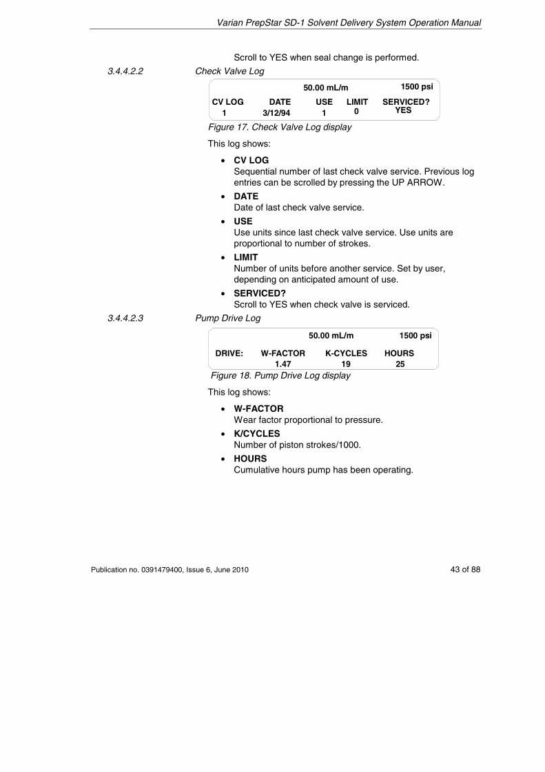
3.4.4.2.2 Check Valve Log
50.00 mL/m 1500 psi
CV LOG DATE LIMITUSE SERVICED?1 3/12/94 01 YES
Figure 17. Check Valve Log display
This log shows:
• CV LOG Sequential number of last check valve service. Previous log entries can be scrolled by pressing the UP ARROW.
• DATE Date of last check valve service.
• USE Use units since last check valve service. Use units are proportional to number of strokes.
• LIMIT Number of units before another service. Set by user, depending on anticipated amount of use.
• SERVICED? Scroll to YES when check valve is serviced.
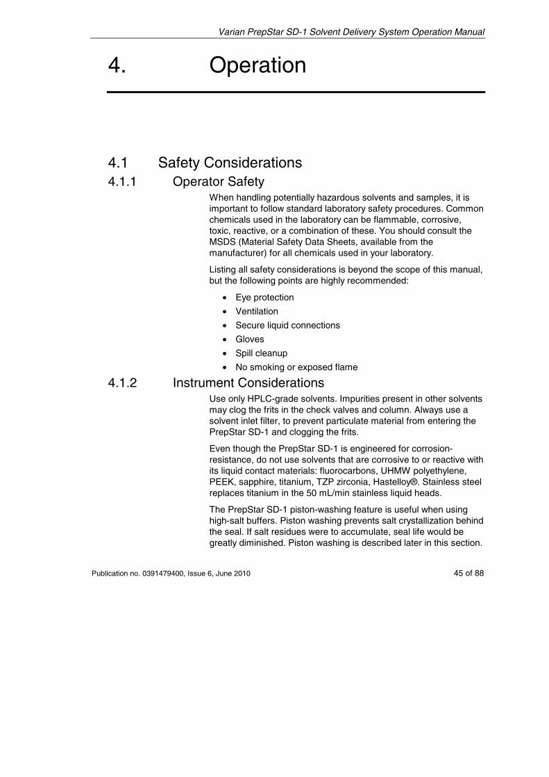
3.4.4.2.3 Pump Drive Log
W-FACTOR1.47
K-CYCLES19
HOURS25
DRIVE:
50.00 mL/m 1500 psi
Figure 18. Pump Drive Log display
This log shows:
• W-FACTOR Wear factor proportional to pressure.
• K/CYCLES Number of piston strokes/1000.
• HOURS Cumulative hours pump has been operating.

Varian PrepStar SD-1 Solvent Delivery System Operation Manual
44 of 88 Publication no. 0391479400, Issue 6, June 2010
This page is intentionally left blank.
Varian PrepStar SD-1 Solvent Delivery System Operation Manual
Publication no. 0391479400, Issue 6, June 2010 45 of 88
4. Operation
4.1 Safety Considerations 4.1.1 Operator Safety
When handling potentially hazardous solvents and samples, it is important to follow standard laboratory safety procedures. Common chemicals used in the laboratory can be flammable, corrosive, toxic, reactive, or a combination of these. You should consult the MSDS (Material Safety Data Sheets, available from the manufacturer) for all chemicals used in your laboratory.
Listing all safety considerations is beyond the scope of this manual, but the following points are highly recommended:
• Eye protection
• Ventilation
• Secure liquid connections
• Gloves
• Spill cleanup
• No smoking or exposed flame
4.1.2 Instrument Considerations Use only HPLC-grade solvents. Impurities present in other solvents may clog the frits in the check valves and column. Always use a solvent inlet filter, to prevent particulate material from entering the PrepStar SD-1 and clogging the frits.
Even though the PrepStar SD-1 is engineered for corrosion-resistance, do not use solvents that are corrosive to or reactive with its liquid contact materials: fluorocarbons, UHMW polyethylene, PEEK, sapphire, titanium, TZP zirconia, Hastelloy®. Stainless steel replaces titanium in the 50 mL/min stainless liquid heads.
The PrepStar SD-1 piston-washing feature is useful when using high-salt buffers. Piston washing prevents salt crystallization behind the seal. If salt residues were to accumulate, seal life would be greatly diminished. Piston washing is described later in this section.
Varian PrepStar SD-1 Solvent Delivery System Operation Manual
46 of 88 Publication no. 0391479400, Issue 6, June 2010
As well as washing the pistons, after using high-salt buffers always pump at least 50 mL of HPLC-grade water through the pumping system to flush away salt deposits from the liquid heads and outlet lines.
Never let the PrepStar SD-1 stand overnight with high-salt buffer solution in the liquid heads. If this should happen, it is important to wash the pistons and flush the liquid heads with water at a low flow rate before starting work.
Do not change directly between immiscible solvents; any resulting precipitation would be extremely difficult to remove from the liquid heads, check valves, and tubing. Consult the Solvent Miscibility Table in Appendix 2. If the solvent you wish to use is immiscible with the solvent in the system change to it via another solvent (or a series) that is miscible with both.
You should always use the PrepStar SD-1 pressure-limiting feature to protect the HPLC column from overpressure which could damage the column and impair performance. The PrepStar SD-1 maximum pressure control is described later in this section. The dynamic pressure is always shown in the top line of the display. It is good practice to monitor this value and be prepared to stop the pump should pressure rise rapidly.
Always use the ramp time feature when changing flow rates, especially if there is a large change. A ramp is a linear change from the current flow rate to the new flow rate, over the set duration. The PrepStar SD-1 can handle large abrupt changes in flow rate without any problem, but the HPLC column may be damaged by pressure shock resulting from such abrupt changes.
If the flow rate ramp up is very rapid or the outlet plumbing is suddenly blocked, for instance by the operation of the sample inject valve, a pressure spike well in excess of the set pressure limit may be generated. This spike may even exceed the capacity of the outlet tubing and/or fittings.
4.2 Initial Operation Before pumping solvent through an HPLC system, it is important to:
• Flush all tubing to prevent impurities or particulates from the new tubing (such as dust, cutting oils, metal swarf, etc.) from clogging the column frit or contaminating the column.
• Check the system for leaks against column backpressure, and tighten any leaking fittings.
Varian PrepStar SD-1 Solvent Delivery System Operation Manual
Publication no. 0391479400, Issue 6, June 2010 47 of 88
The following procedure steps through flushing the system and checking for leaks.
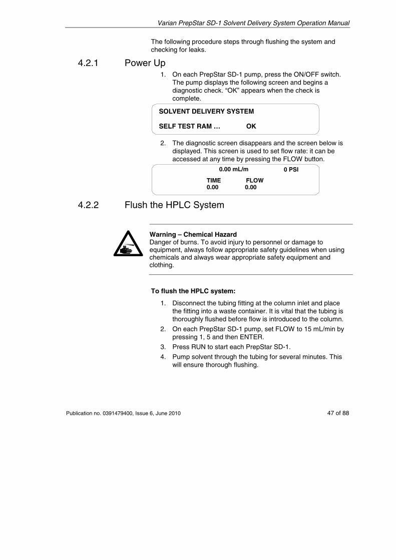
4.2.1 Power Up 1. On each PrepStar SD-1 pump, press the ON/OFF switch.
The pump displays the following screen and begins a diagnostic check. “OK” appears when the check is complete.
SOLVENT DELIVERY SYSTEM
SELF TEST RAM … OK
2. The diagnostic screen disappears and the screen below is displayed. This screen is used to set flow rate: it can be accessed at any time by pressing the FLOW button.
0 PSI0.00 mL/m
TIME FLOW0.00 0.00
4.2.2 Flush the HPLC System
Warning – Chemical Hazard Danger of burns. To avoid injury to personnel or damage to equipment, always follow appropriate safety guidelines when using chemicals and always wear appropriate safety equipment and clothing.
To flush the HPLC system:
1. Disconnect the tubing fitting at the column inlet and place the fitting into a waste container. It is vital that the tubing is thoroughly flushed before flow is introduced to the column.
2. On each PrepStar SD-1 pump, set FLOW to 15 mL/min by pressing 1, 5 and then ENTER.
3. Press RUN to start each PrepStar SD-1.
4. Pump solvent through the tubing for several minutes. This will ensure thorough flushing.
Varian PrepStar SD-1 Solvent Delivery System Operation Manual
48 of 88 Publication no. 0391479400, Issue 6, June 2010
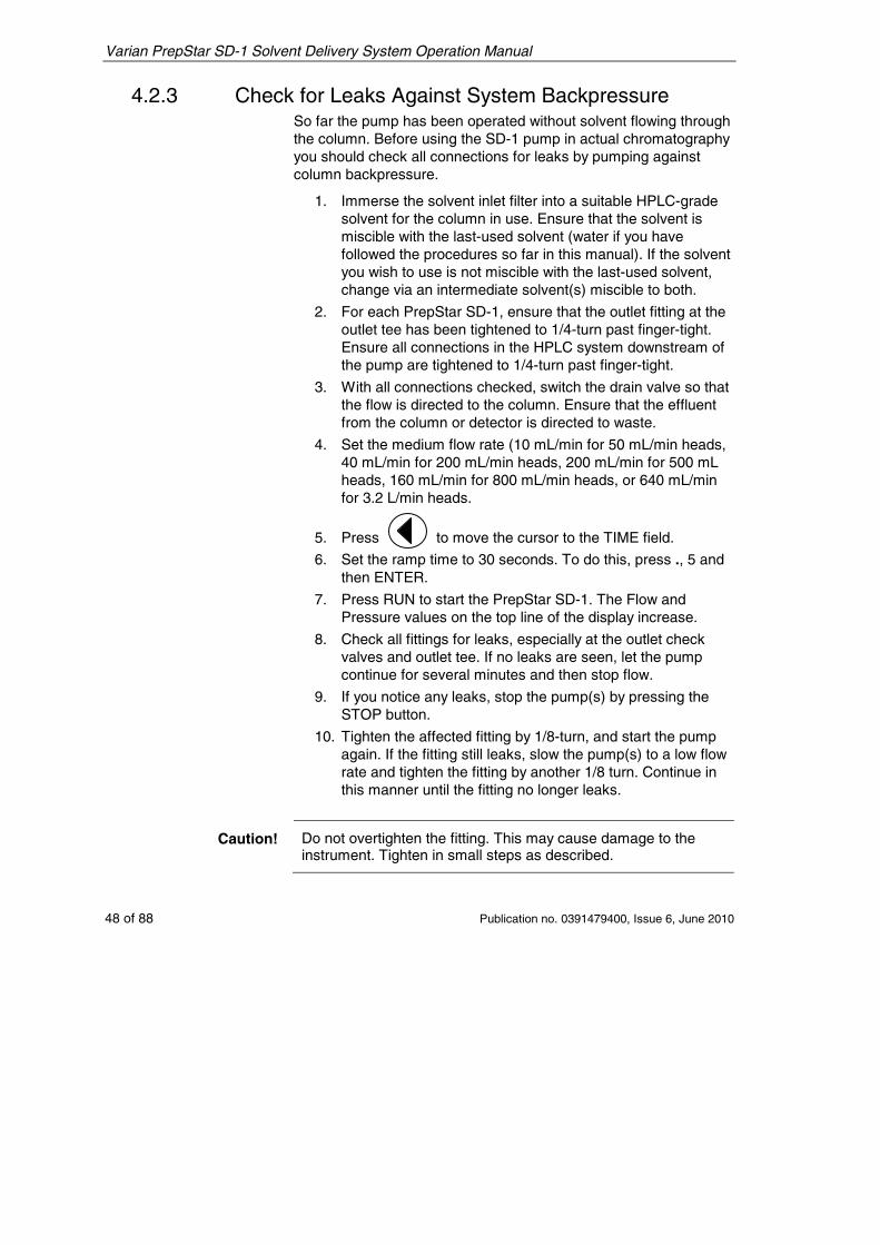
4.2.3 Check for Leaks Against System Backpressure So far the pump has been operated without solvent flowing through the column. Before using the SD-1 pump in actual chromatography you should check all connections for leaks by pumping against column backpressure.
1. Immerse the solvent inlet filter into a suitable HPLC-grade solvent for the column in use. Ensure that the solvent is miscible with the last-used solvent (water if you have followed the procedures so far in this manual). If the solvent you wish to use is not miscible with the last-used solvent, change via an intermediate solvent(s) miscible to both.
2. For each PrepStar SD-1, ensure that the outlet fitting at the outlet tee has been tightened to 1/4-turn past finger-tight. Ensure all connections in the HPLC system downstream of the pump are tightened to 1/4-turn past finger-tight.
3. With all connections checked, switch the drain valve so that the flow is directed to the column. Ensure that the effluent from the column or detector is directed to waste.
4. Set the medium flow rate (10 mL/min for 50 mL/min heads, 40 mL/min for 200 mL/min heads, 200 mL/min for 500 mL heads, 160 mL/min for 800 mL/min heads, or 640 mL/min for 3.2 L/min heads.
5. Press to move the cursor to the TIME field.
6. Set the ramp time to 30 seconds. To do this, press ., 5 and then ENTER.
7. Press RUN to start the PrepStar SD-1. The Flow and Pressure values on the top line of the display increase.
8. Check all fittings for leaks, especially at the outlet check valves and outlet tee. If no leaks are seen, let the pump continue for several minutes and then stop flow.
9. If you notice any leaks, stop the pump(s) by pressing the STOP button.
10. Tighten the affected fitting by 1/8-turn, and start the pump again. If the fitting still leaks, slow the pump(s) to a low flow rate and tighten the fitting by another 1/8 turn. Continue in this manner until the fitting no longer leaks.
Caution! Do not overtighten the fitting. This may cause damage to the instrument. Tighten in small steps as described.
Varian PrepStar SD-1 Solvent Delivery System Operation Manual
Publication no. 0391479400, Issue 6, June 2010 49 of 88
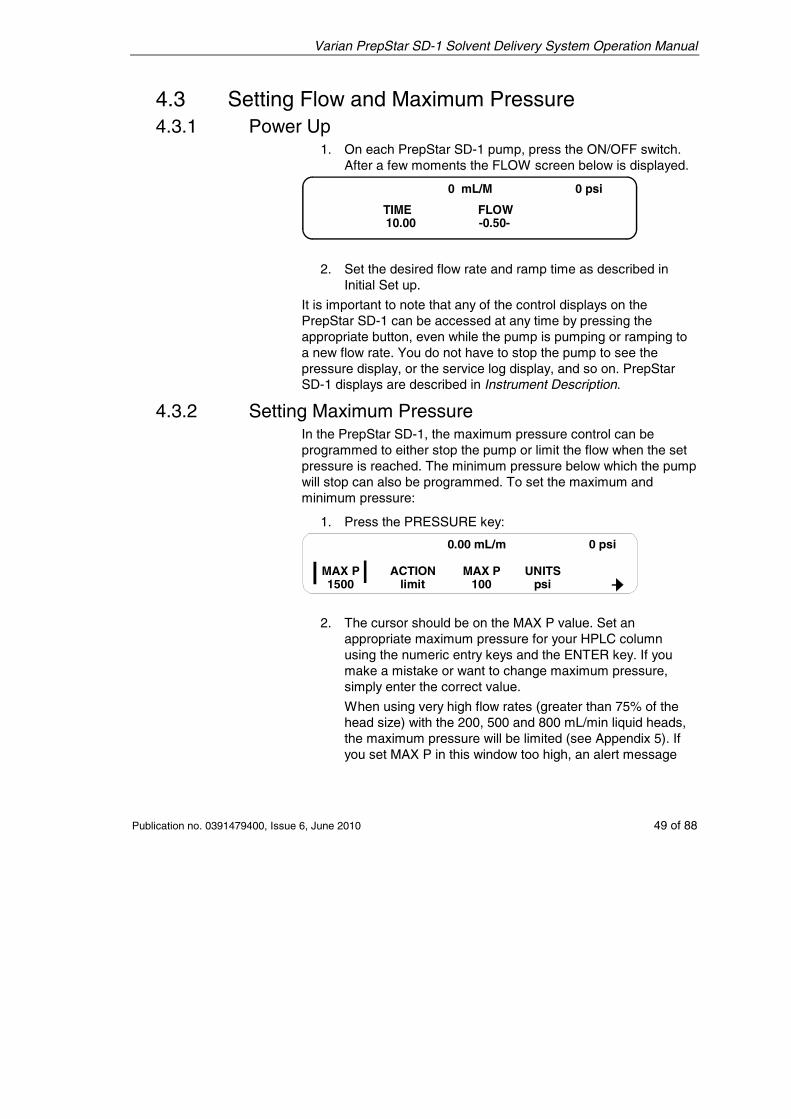
4.3 Setting Flow and Maximum Pressure 4.3.1 Power Up
1. On each PrepStar SD-1 pump, press the ON/OFF switch. After a few moments the FLOW screen below is displayed.
0 mL/M 0 psi
TIME FLOW10.00 -0.50-
2. Set the desired flow rate and ramp time as described in Initial Set up.
It is important to note that any of the control displays on the PrepStar SD-1 can be accessed at any time by pressing the appropriate button, even while the pump is pumping or ramping to a new flow rate. You do not have to stop the pump to see the pressure display, or the service log display, and so on. PrepStar SD-1 displays are described in Instrument Description.
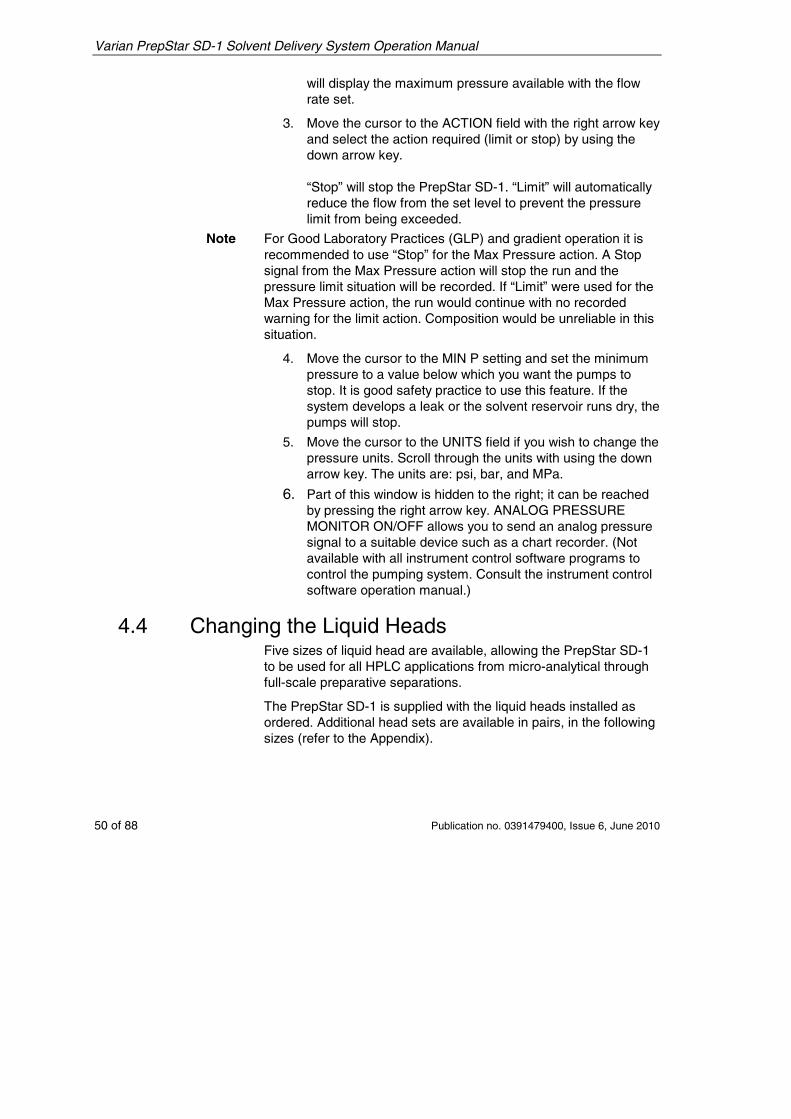
4.3.2 Setting Maximum Pressure In the PrepStar SD-1, the maximum pressure control can be programmed to either stop the pump or limit the flow when the set pressure is reached. The minimum pressure below which the pump will stop can also be programmed. To set the maximum and minimum pressure:
1. Press the PRESSURE key:
MAX P1500
MAX P100
ACTIONlimit
UNITSpsi
0.00 mL/m 0 psi
2. The cursor should be on the MAX P value. Set an appropriate maximum pressure for your HPLC column using the numeric entry keys and the ENTER key. If you make a mistake or want to change maximum pressure, simply enter the correct value.
When using very high flow rates (greater than 75% of the head size) with the 200, 500 and 800 mL/min liquid heads, the maximum pressure will be limited (see Appendix 5). If you set MAX P in this window too high, an alert message
Varian PrepStar SD-1 Solvent Delivery System Operation Manual
50 of 88 Publication no. 0391479400, Issue 6, June 2010
will display the maximum pressure available with the flow rate set.
3. Move the cursor to the ACTION field with the right arrow key and select the action required (limit or stop) by using the down arrow key. “Stop” will stop the PrepStar SD-1. “Limit” will automatically reduce the flow from the set level to prevent the pressure limit from being exceeded.
Note For Good Laboratory Practices (GLP) and gradient operation it is recommended to use “Stop” for the Max Pressure action. A Stop signal from the Max Pressure action will stop the run and the pressure limit situation will be recorded. If “Limit” were used for the Max Pressure action, the run would continue with no recorded warning for the limit action. Composition would be unreliable in this situation.
4. Move the cursor to the MIN P setting and set the minimum pressure to a value below which you want the pumps to stop. It is good safety practice to use this feature. If the system develops a leak or the solvent reservoir runs dry, the pumps will stop.
5. Move the cursor to the UNITS field if you wish to change the pressure units. Scroll through the units with using the down arrow key. The units are: psi, bar, and MPa.
6. Part of this window is hidden to the right; it can be reached by pressing the right arrow key. ANALOG PRESSURE MONITOR ON/OFF allows you to send an analog pressure signal to a suitable device such as a chart recorder. (Not available with all instrument control software programs to control the pumping system. Consult the instrument control software operation manual.)
4.4 Changing the Liquid Heads Five sizes of liquid head are available, allowing the PrepStar SD-1 to be used for all HPLC applications from micro-analytical through full-scale preparative separations.
The PrepStar SD-1 is supplied with the liquid heads installed as ordered. Additional head sets are available in pairs, in the following sizes (refer to the Appendix).
Varian PrepStar SD-1 Solvent Delivery System Operation Manual
Publication no. 0391479400, Issue 6, June 2010 51 of 88
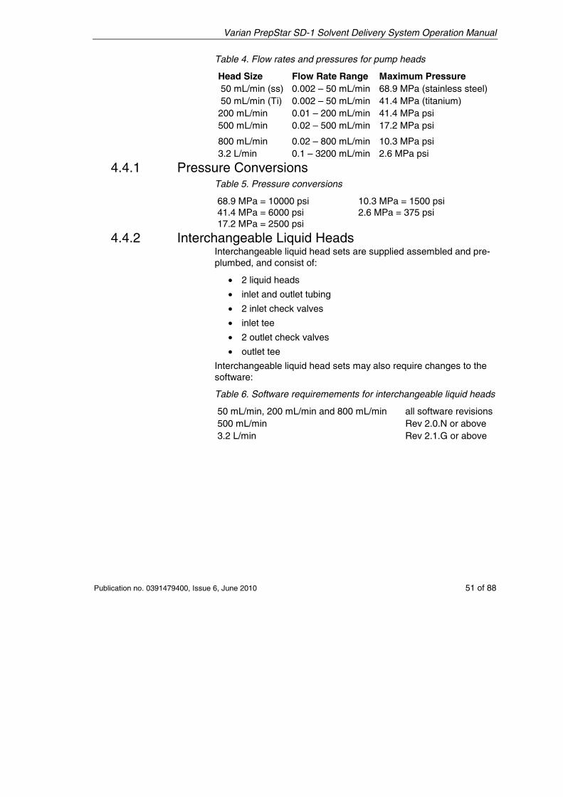
Table 4. Flow rates and pressures for pump heads
Head Size Flow Rate Range Maximum Pressure 50 mL/min (ss) 0.002 – 50 mL/min 68.9 MPa (stainless steel) 50 mL/min (Ti) 0.002 – 50 mL/min 41.4 MPa (titanium) 200 mL/min 0.01 – 200 mL/min 41.4 MPa psi 500 mL/min 0.02 – 500 mL/min 17.2 MPa psi
800 mL/min 0.02 – 800 mL/min 10.3 MPa psi 3.2 L/min 0.1 – 3200 mL/min 2.6 MPa psi
4.4.1 Pressure Conversions Table 5. Pressure conversions
68.9 MPa = 10000 psi 41.4 MPa = 6000 psi 17.2 MPa = 2500 psi
10.3 MPa = 1500 psi 2.6 MPa = 375 psi
4.4.2 Interchangeable Liquid Heads Interchangeable liquid head sets are supplied assembled and pre-plumbed, and consist of:
• 2 liquid heads
• inlet and outlet tubing
• 2 inlet check valves
• inlet tee
• 2 outlet check valves
• outlet tee
Interchangeable liquid head sets may also require changes to the software:
Table 6. Software requiremements for interchangeable liquid heads
50 mL/min, 200 mL/min and 800 mL/min all software revisions500 mL/min Rev 2.0.N or above 3.2 L/min Rev 2.1.G or above
Varian PrepStar SD-1 Solvent Delivery System Operation Manual
52 of 88 Publication no. 0391479400, Issue 6, June 2010
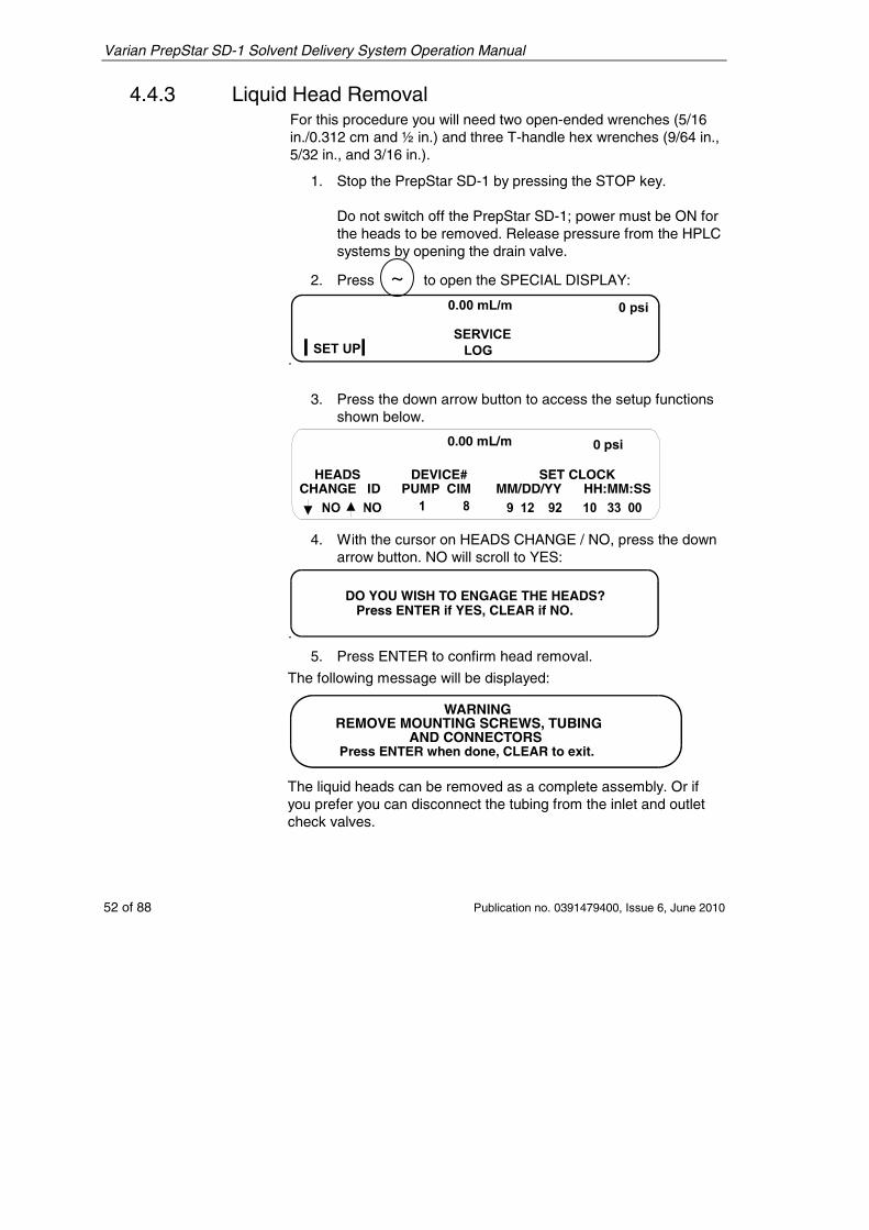
4.4.3 Liquid Head Removal For this procedure you will need two open-ended wrenches (5/16 in./0.312 cm and ½ in.) and three T-handle hex wrenches (9/64 in., 5/32 in., and 3/16 in.).
1. Stop the PrepStar SD-1 by pressing the STOP key. Do not switch off the PrepStar SD-1; power must be ON for the heads to be removed. Release pressure from the HPLC systems by opening the drain valve.
2. Press ~ to open the SPECIAL DISPLAY:
3. Press the down arrow button to access the setup functions
shown below.
0.00 mL/m 0 psi
HEADSCHANGE ID
DEVICE#PUMP CIM
SET CLOCKMM/DD/YY HH:MM:SS
4. With the cursor on HEADS CHANGE / NO, press the down arrow button. NO will scroll to YES:
DO YOU WISH TO ENGAGE THE HEADS? Press ENTER if YES, CLEAR if NO.
5. Press ENTER
to confirm head removal.
The following message will be displayed:
WARNINGREMOVE MOUNTING SCREWS, TUBING
AND CONNECTORSPress ENTER when done, CLEAR to exit.
The liquid heads can be removed as a complete assembly. Or if you prefer you can disconnect the tubing from the inlet and outlet check valves.
Varian PrepStar SD-1 Solvent Delivery System Operation Manual
Publication no. 0391479400, Issue 6, June 2010 53 of 88
Layer 1200
Ti200
200200
Ti200Ti
SEEDETAIL
LOCATION OF MOUNTING SCREWS
KNURLEDCOLLAR ALIGNMENT
MARK
DETAILOF PRESSURESIGNALCABLECONNECTOR
REMOVETHESEFITTINGSTOACCESSMOUNTING SCREWSRemove these fittings toaccess mounting screws.
Detail of pressure signalcable connector
KnurledCollar Alignment
Mark
Location of mounting screws
See Detail
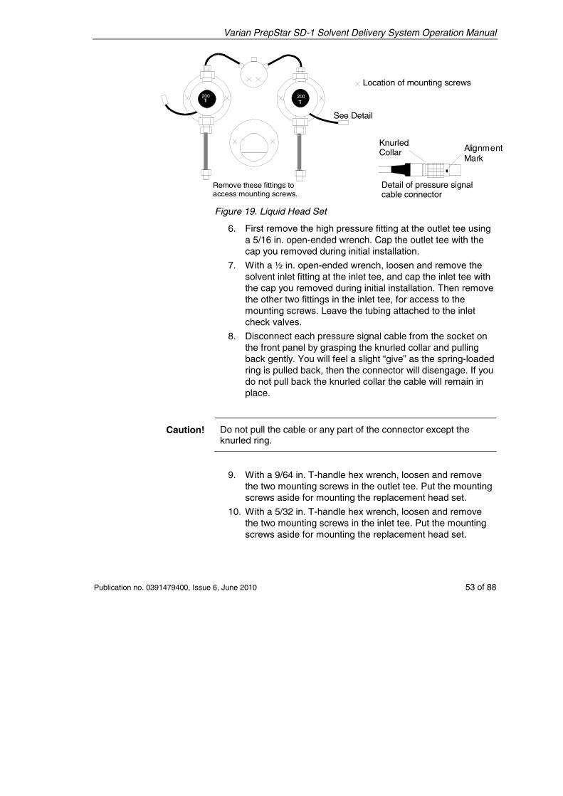
Figure 19. Liquid Head Set
6. First remove the high pressure fitting at the outlet tee using a 5/16 in. open-ended wrench. Cap the outlet tee with the cap you removed during initial installation.
7. With a ½ in. open-ended wrench, loosen and remove the solvent inlet fitting at the inlet tee, and cap the inlet tee with the cap you removed during initial installation. Then remove the other two fittings in the inlet tee, for access to the mounting screws. Leave the tubing attached to the inlet check valves.
8. Disconnect each pressure signal cable from the socket on the front panel by grasping the knurled collar and pulling back gently. You will feel a slight “give” as the spring-loaded ring is pulled back, then the connector will disengage. If you do not pull back the knurled collar the cable will remain in place.
Caution! Do not pull the cable or any part of the connector except the knurled ring.
9. With a 9/64 in. T-handle hex wrench, loosen and remove the two mounting screws in the outlet tee. Put the mounting screws aside for mounting the replacement head set.
10. With a 5/32 in. T-handle hex wrench, loosen and remove the two mounting screws in the inlet tee. Put the mounting screws aside for mounting the replacement head set.
Varian PrepStar SD-1 Solvent Delivery System Operation Manual
54 of 88 Publication no. 0391479400, Issue 6, June 2010
11. With a 3/16 in. T-handle hex wrench, loosen and remove the two mounting screws in both liquid heads. Put the mounting screws aside for mounting the replacement head set.
12. Preparation is complete. Now the PrepStar SD-1 software will disengage the heads.
13. Press ENTER to confirm removal of mounting screws.
After pressing ENTER, the PrepStar SD-1 will start the disengagement sequence. One at a time the liquid heads will be pushed out from the front panel. Support the weight of the liquid heads during disengagement.
When the heads are fully disengaged, the display will read as follows:
HEADS DISENGAGED. REMOVE AND REPLACE Press ENTER when completed.
14. Remove each head by pulling it away from the front panel. You will have to overcome slight resistance from the spring in the collet.
15. At the same time, remove the inlet and outlet tees. Put the complete assembly aside.
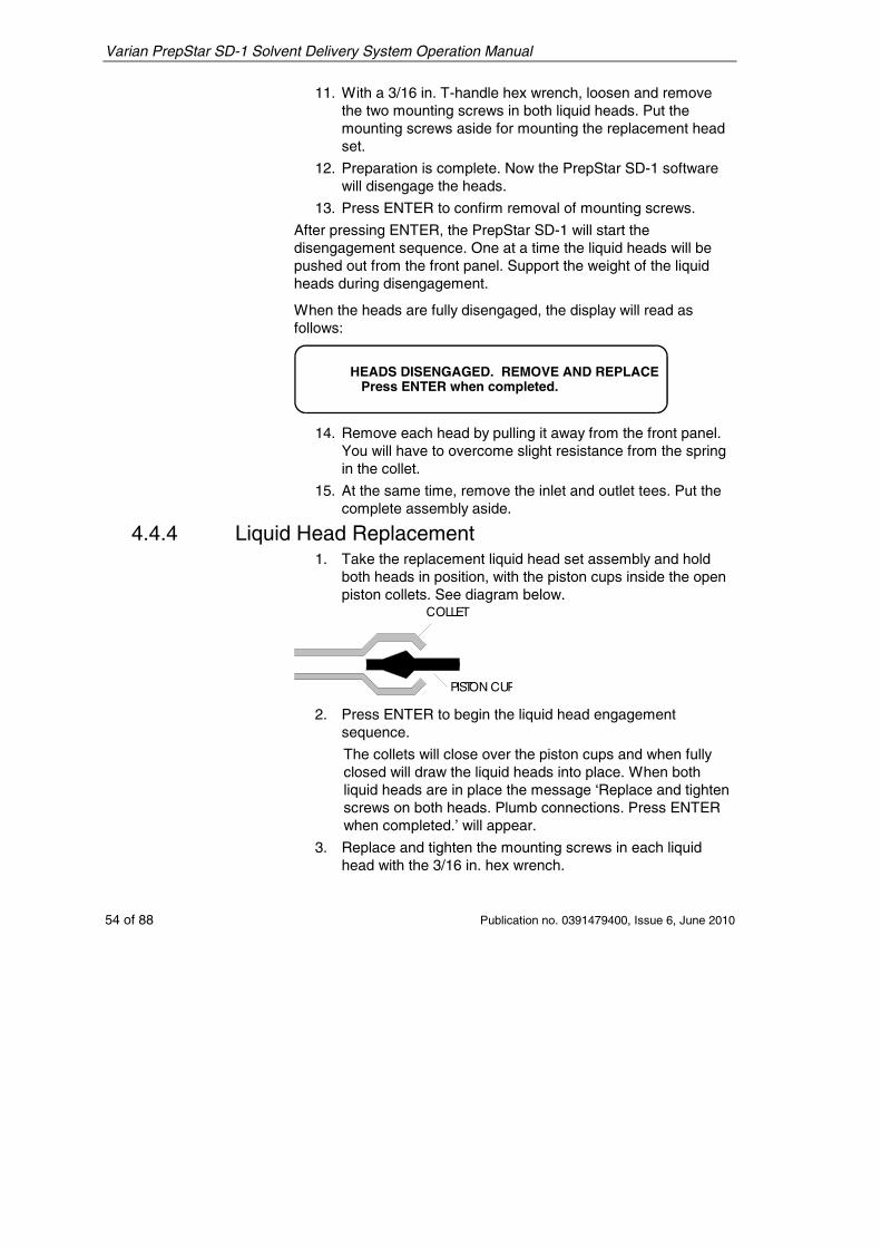
4.4.4 Liquid Head Replacement 1. Take the replacement liquid head set assembly and hold
both heads in position, with the piston cups inside the open piston collets. See diagram below.
COLLET
PISTON CUP
2. Press ENTER
to begin the liquid head engagement sequence.
The collets will close over the piston cups and when fully closed will draw the liquid heads into place. When both liquid heads are in place the message ‘Replace and tighten screws on both heads. Plumb connections. Press ENTER when completed.’ will appear.
3. Replace and tighten the mounting screws in each liquid head with the 3/16 in. hex wrench.
Varian PrepStar SD-1 Solvent Delivery System Operation Manual
Publication no. 0391479400, Issue 6, June 2010 55 of 88
4. Replace and tighten the mounting screws in the inlet tee with the 5/32 in. hex wrench.
5. Replace and tighten the mounting screws in the outlet tee with the 9/64 in. hex wrench.
6. Replace the low pressure inlet fitting in the inlet tee with the ½ in. open-ended wrench and tighten 1/4-turn past finger-tight. Connect the inlet tubing (tee to inlet check valves).
7. Replace the high pressure outlet fitting in the outlet tee with the 5/16 in. open-ended wrench and tighten 1/4-turn past finger-tight.
Warning – Chemical Hazard Personal injury may occur due to solvent leaks if the pump is operated with liquid heads not properly mounted. Always wear appropriate safety clothing and equipment when working with solvents.
Caution! The PrepStar SD-1 software cannot tell whether or not you have actually replaced the mounting screws. To prevent leaks and damage to the instrument it is extremely important that the mounting screws are properly attached before attempting to operate the PrepStar SD-1.
8. Press ENTER to confirm the mounting screws and plumbing are connected. When you have done this the message ‘Plug in BOTH connectors. Press ENTER when completed.’ will appear.
9. Reconnect the pressure signal cables.
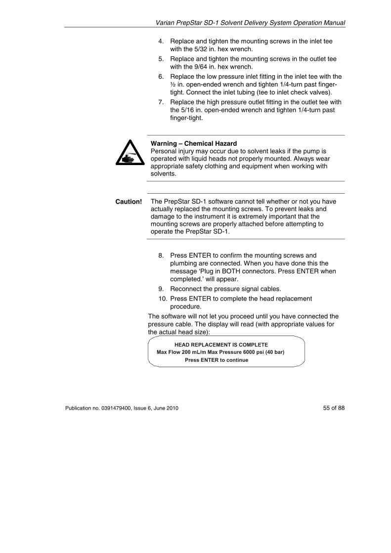
10. Press ENTER to complete the head replacement procedure.
The software will not let you proceed until you have connected the pressure cable. The display will read (with appropriate values for the actual head size):
Varian PrepStar SD-1 Solvent Delivery System Operation Manual
56 of 88 Publication no. 0391479400, Issue 6, June 2010
4.5 Remote Operation This section provides a brief introduction to remote control by your instrument control software.
For complete information you should also read the instrument control software manual.
For remote control:
1. Make the connections between the computer and the PrepStar SD-1 pumps as shown in Figure 5. The connections are described fully in Electrical Setup on page 15. Also make connections to the external contacts panel, also described on page 10.
2. For your instrument control software to control your pumps, each device must have a unique device ID number. ID numbers are set in the PrepStar SD-1 Set Up display.
3. Press the SPECIAL key to open the SPECIAL display. Then press the down arrow key to open the Set Up display.
4. The ID numbers are shown on the bottom line, in this case Pump ID, 1 and CIM ID, 8. Set these numbers as desired by scrolling with the up/down arrow keys.
Note If you have two pumps, only one of the built-in CIM (Control Interface Modules) should be used if required. Set the second CIM ID number to – –, first enter a 63, and then push the vertical arrow key. Internal CIM ID number is set only when the internal CIM is used to start data collection or another instrument.
5. When you have set ID numbers for all devices in your system, refer to your instrument control software manual for details on how to use remote operation and how to set up additional electrical connections, depending upon your particular system requirements. E.g., connections for wavelength control of a detector, fraction collector contacts out, and so on.
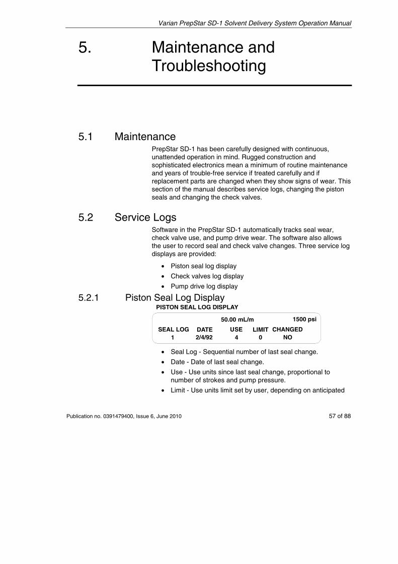
Varian PrepStar SD-1 Solvent Delivery System Operation Manual
Publication no. 0391479400, Issue 6, June 2010 57 of 88
5. Maintenance and Troubleshooting
5.1 Maintenance PrepStar SD-1 has been carefully designed with continuous, unattended operation in mind. Rugged construction and sophisticated electronics mean a minimum of routine maintenance and years of trouble-free service if treated carefully and if replacement parts are changed when they show signs of wear. This section of the manual describes service logs, changing the piston seals and changing the check valves.
5.2 Service Logs Software in the PrepStar SD-1 automatically tracks seal wear, check valve use, and pump drive wear. The software also allows the user to record seal and check valve changes. Three service log displays are provided:
• Piston seal log display
• Check valves log display
• Pump drive log display
5.2.1 Piston Seal Log Display
50.00 mL/m 1500 psi
PISTON SEAL LOG DISPLAY
SEAL LOG DATE LIMITUSE CHANGED1 2/4/92 04 NO
• Seal Log - Sequential number of last seal change.
• Date - Date of last seal change.
• Use - Use units since last seal change, proportional to number of strokes and pump pressure.
• Limit - Use units limit set by user, depending on anticipated
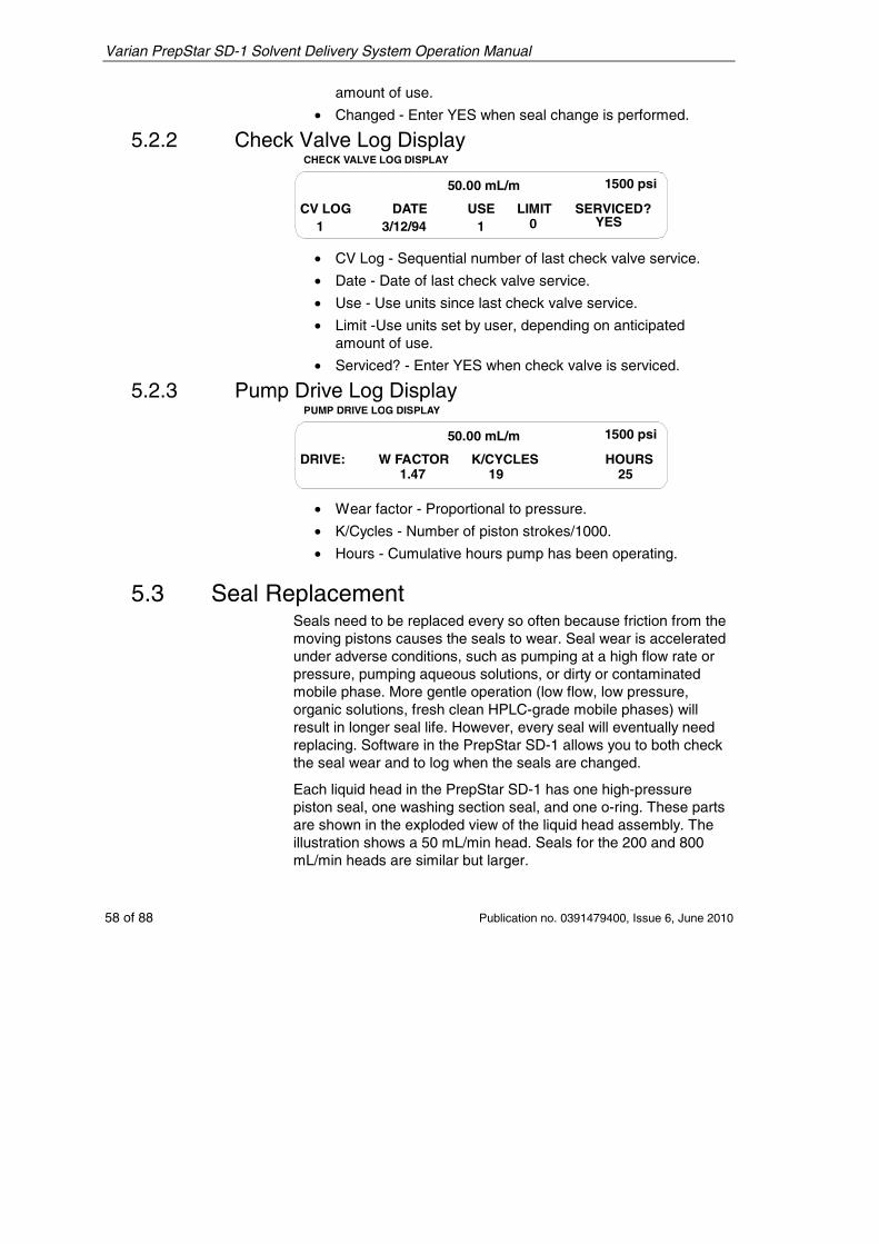
Varian PrepStar SD-1 Solvent Delivery System Operation Manual
58 of 88 Publication no. 0391479400, Issue 6, June 2010
amount of use.
• Changed - Enter YES when seal change is performed.
5.2.2 Check Valve Log Display
50.00 mL/m 1500 psi
CHECK VALVE LOG DISPLAY
CV LOG DATE LIMITUSE SERVICED?1 3/12/94 01 YES
• CV Log - Sequential number of last check valve service.
• Date - Date of last check valve service.
• Use - Use units since last check valve service.
• Limit -Use units set by user, depending on anticipated amount of use.
• Serviced? - Enter YES when check valve is serviced.
5.2.3 Pump Drive Log Display
50.00 mL/m 1500 psi
PUMP DRIVE LOG DISPLAY
DRIVE: W FACTOR K/CYCLES HOURS1.47 19 25
• Wear factor - Proportional to pressure.
• K/Cycles - Number of piston strokes/1000.
• Hours - Cumulative hours pump has been operating.
5.3 Seal Replacement Seals need to be replaced every so often because friction from the moving pistons causes the seals to wear. Seal wear is accelerated under adverse conditions, such as pumping at a high flow rate or pressure, pumping aqueous solutions, or dirty or contaminated mobile phase. More gentle operation (low flow, low pressure, organic solutions, fresh clean HPLC-grade mobile phases) will result in longer seal life. However, every seal will eventually need replacing. Software in the PrepStar SD-1 allows you to both check the seal wear and to log when the seals are changed.
Each liquid head in the PrepStar SD-1 has one high-pressure piston seal, one washing section seal, and one o-ring. These parts are shown in the exploded view of the liquid head assembly. The illustration shows a 50 mL/min head. Seals for the 200 and 800 mL/min heads are similar but larger.
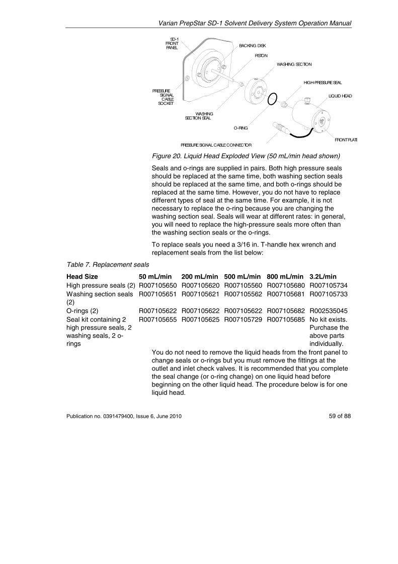
Varian PrepStar SD-1 Solvent Delivery System Operation Manual
Publication no. 0391479400, Issue 6, June 2010 59 of 88
BACKING DISK
PISTON
WASHING SECTION
HIGH-PRESSURESEAL
LIQUID HEAD
PRESSURESIGNALCABLECONNECTOR
O-RING
WASHINGSECTION SEAL
PRESSURESIGNALCABLE
SOCKET
SD-1FRONTPANEL
FRONTPLATE
Figure 20. Liquid Head Exploded View (50 mL/min head shown)
Seals and o-rings are supplied in pairs. Both high pressure seals should be replaced at the same time, both washing section seals should be replaced at the same time, and both o-rings should be replaced at the same time. However, you do not have to replace different types of seal at the same time. For example, it is not necessary to replace the o-ring because you are changing the washing section seal. Seals will wear at different rates: in general, you will need to replace the high-pressure seals more often than the washing section seals or the o-rings.
To replace seals you need a 3/16 in. T-handle hex wrench and replacement seals from the list below:
Table 7. Replacement seals
Head Size 50 mL/min 200 mL/min 500 mL/min 800 mL/min 3.2L/min High pressure seals (2) R007105650 R007105620 R007105560 R007105680 R007105734Washing section seals (2)
R007105651 R007105621 R007105562 R007105681 R007105733
O-rings (2) R007105622 R007105622 R007105622 R007105682 R002535045Seal kit containing 2 high pressure seals, 2 washing seals, 2 o-rings
R007105655 R007105625 R007105729 R007105685 No kit exists. Purchase the above parts individually.
You do not need to remove the liquid heads from the front panel to change seals or o-rings but you must remove the fittings at the outlet and inlet check valves. It is recommended that you complete the seal change (or o-ring change) on one liquid head before beginning on the other liquid head. The procedure below is for one liquid head.
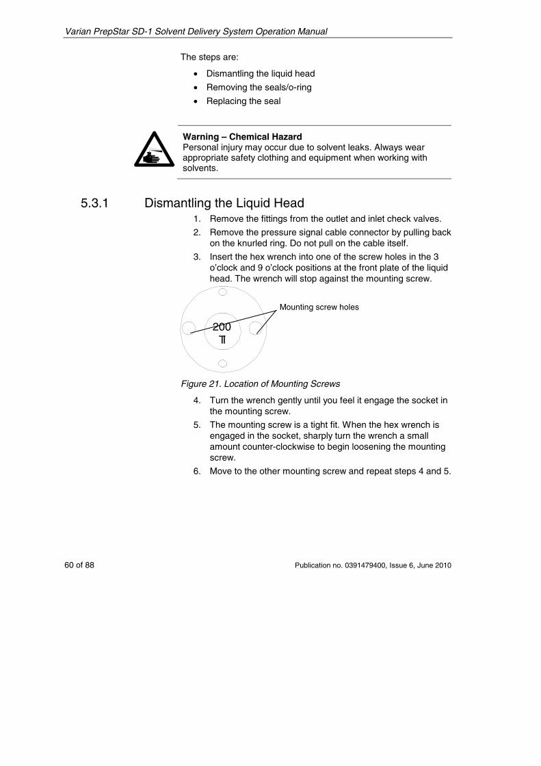
Varian PrepStar SD-1 Solvent Delivery System Operation Manual
60 of 88 Publication no. 0391479400, Issue 6, June 2010
The steps are:
• Dismantling the liquid head
• Removing the seals/o-ring
• Replacing the seal
Warning – Chemical Hazard Personal injury may occur due to solvent leaks. Always wear appropriate safety clothing and equipment when working with solvents.
5.3.1 Dismantling the Liquid Head 1. Remove the fittings from the outlet and inlet check valves.
2. Remove the pressure signal cable connector by pulling back on the knurled ring. Do not pull on the cable itself.
3. Insert the hex wrench into one of the screw holes in the 3 o’clock and 9 o’clock positions at the front plate of the liquid head. The wrench will stop against the mounting screw.
200TI
Figure 21. Location of Mounting Screws
4. Turn the wrench gently until you feel it engage the socket in the mounting screw.
5. The mounting screw is a tight fit. When the hex wrench is engaged in the socket, sharply turn the wrench a small amount counter-clockwise to begin loosening the mounting screw.
6. Move to the other mounting screw and repeat steps 4 and 5.
Mounting screw holes
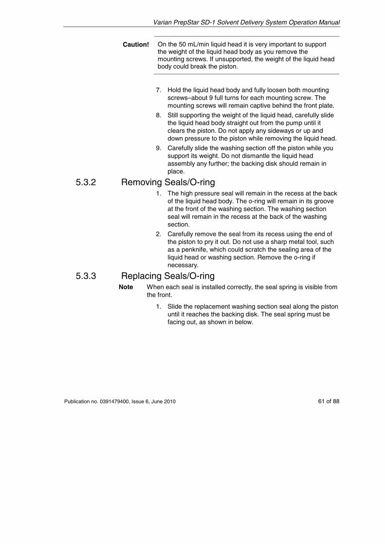
Varian PrepStar SD-1 Solvent Delivery System Operation Manual
Publication no. 0391479400, Issue 6, June 2010 61 of 88
Caution! On the 50 mL/min liquid head it is very important to support the weight of the liquid head body as you remove the mounting screws. If unsupported, the weight of the liquid head body could break the piston.
7. Hold the liquid head body and fully loosen both mounting screws–about 9 full turns for each mounting screw. The mounting screws will remain captive behind the front plate.
8. Still supporting the weight of the liquid head, carefully slide the liquid head body straight out from the pump until it clears the piston. Do not apply any sideways or up and down pressure to the piston while removing the liquid head.
9. Carefully slide the washing section off the piston while you support its weight. Do not dismantle the liquid head assembly any further; the backing disk should remain in place.
5.3.2 Removing Seals/O-ring 1. The high pressure seal will remain in the recess at the back
of the liquid head body. The o-ring will remain in its groove at the front of the washing section. The washing section seal will remain in the recess at the back of the washing section.
2. Carefully remove the seal from its recess using the end of the piston to pry it out. Do not use a sharp metal tool, such as a penknife, which could scratch the sealing area of the liquid head or washing section. Remove the o-ring if necessary.
5.3.3 Replacing Seals/O-ring Note When each seal is installed correctly, the seal spring is visible from
the front.
1. Slide the replacement washing section seal along the piston until it reaches the backing disk. The seal spring must be facing out, as shown in below.
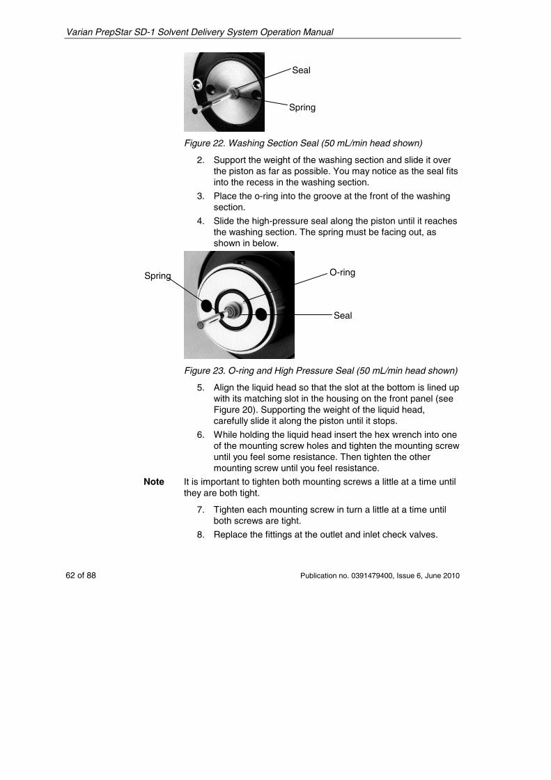
Varian PrepStar SD-1 Solvent Delivery System Operation Manual
62 of 88 Publication no. 0391479400, Issue 6, June 2010
Figure 22. Washing Section Seal (50 mL/min head shown)
2. Support the weight of the washing section and slide it over the piston as far as possible. You may notice as the seal fits into the recess in the washing section.
3. Place the o-ring into the groove at the front of the washing section.
4. Slide the high-pressure seal along the piston until it reaches the washing section. The spring must be facing out, as shown in below.
Figure 23. O-ring and High Pressure Seal (50 mL/min head shown)
5. Align the liquid head so that the slot at the bottom is lined up with its matching slot in the housing on the front panel (see Figure 20). Supporting the weight of the liquid head, carefully slide it along the piston until it stops.
6. While holding the liquid head insert the hex wrench into one of the mounting screw holes and tighten the mounting screw until you feel some resistance. Then tighten the other mounting screw until you feel resistance.
Note It is important to tighten both mounting screws a little at a time until they are both tight.
7. Tighten each mounting screw in turn a little at a time until both screws are tight.
8. Replace the fittings at the outlet and inlet check valves.
O-ring
Seal
Spring
Seal
Spring
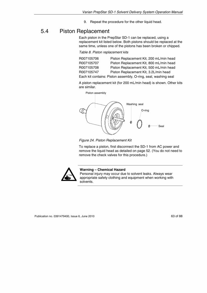
Varian PrepStar SD-1 Solvent Delivery System Operation Manual
Publication no. 0391479400, Issue 6, June 2010 63 of 88
9. Repeat the procedure for the other liquid head.
5.4 Piston Replacement Each piston in the PrepStar SD-1 can be replaced, using a replacement kit listed below. Both pistons should be replaced at the same time, unless one of the pistons has been broken or chipped.
Table 8. Piston replacement kits
R007105706 Piston Replacement Kit, 200 mL/min head R007105707 Piston Replacement Kit, 800 mL/min head R007105708 Piston Replacement Kit, 500 mL/min head R007105747 Piston Replacement Kit, 3.2L/min head Each kit contains: Piston assembly, O-ring, seal, washing seal
A piston replacement kit (for 200 mL/min head) is shown. Other kits are similar.
Figure 24. Piston Replacement Kit
To replace a piston, first disconnect the SD-1 from AC power and remove the liquid head as detailed on page 52. (You do not need to remove the check valves for this procedure.)
Warning – Chemical Hazard Personal injury may occur due to solvent leaks. Always wear appropriate safety clothing and equipment when working with solvents.
Seal
Washing seal
O-ring
Piston assembly
Varian PrepStar SD-1 Solvent Delivery System Operation Manual
64 of 88 Publication no. 0391479400, Issue 6, June 2010
5.4.1 Removing the Old Piston Assembly 1. Hold the liquid head body with on hand and insert the hex
wrench into one of the screw holes in the 3 o’clock and 9 o’clock positions at the front plate of the liquid head. The wrench will stop against the mounting screw.
2. Turn the wrench gently until you feel it engage the socket in the mounting screw.
3. When the hex wrench is engaged in the socket, turn the wrench sharply a small amount counter-clockwise to begin loosening the mounting screw.
4. Move to the other mounting screw and repeat steps 2 and 3.
5. Remove the liquid head (with washing section) from the piston assembly. The old seals and old O-ring will probably remain on the washing section.
6. Carefully slide the washing section away from the liquid head. Remove the backing disk from the old piston assembly.
5.4.2 Installing the New Piston Assembly 1. Take the replacement piston assembly and slide the
backing disk over the piston. Align the holes with the screw holes on the piston assembly. Refer to the photos and instructions in Replacing Seals/O-ring on page 61, and slide the washing seal over the piston.
2. Slide the washing section over the piston and install the new O-ring and seal as shown on page 61.
3. Carefully slide the liquid head over the piston, making sure that the holes are aligned.
4. Using the 3/16 in. hex wrench, tighten each screw until you feel resistance. Then tighten both screws a little at a time until they are both fully tightened.
5. Repeat this procedure for the other liquid head.
5.5 Check Valve Replacement Each liquid head in the PrepStar SD-1 has one inlet check valve and one outlet check valve, as shown.
Warning – Chemical Hazard Personal injury may occur due to solvent leaks. Always wear appropriate safety clothing and equipment when working with solvents.
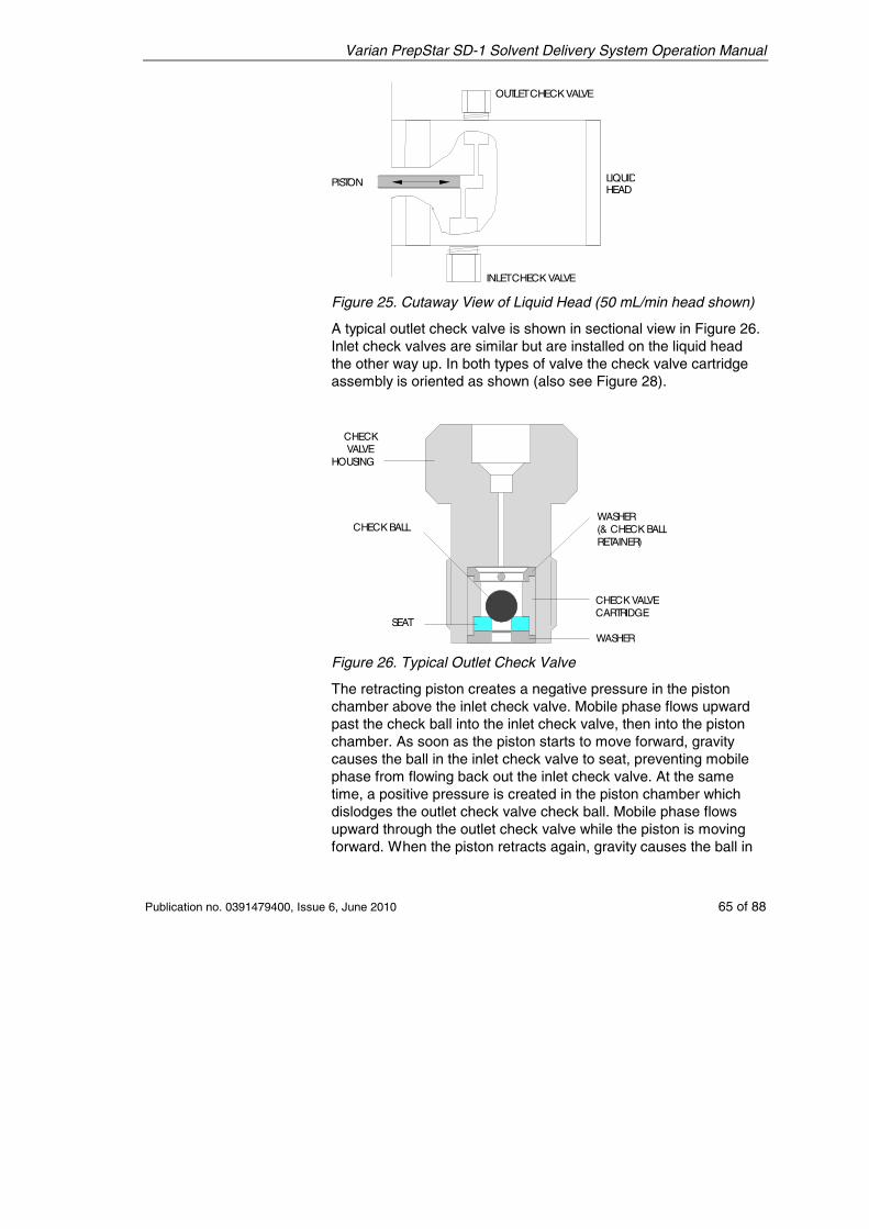
Varian PrepStar SD-1 Solvent Delivery System Operation Manual
Publication no. 0391479400, Issue 6, June 2010 65 of 88
OUTLETCHECKVALVE
INLETCHECK VALVE
PISTON LIQUIDHEAD
Figure 25. Cutaway View of Liquid Head (50 mL/min head shown)
A typical outlet check valve is shown in sectional view in Figure 26. Inlet check valves are similar but are installed on the liquid head the other way up. In both types of valve the check valve cartridge assembly is oriented as shown (also see Figure 28).
CHECKVALVE
HOUSING
WASHER(& CHECK BALLRETAINER)
CHECK VALVECARTRIDGE
WASHER
CHECK BALL
SEAT
Figure 26. Typical Outlet Check Valve
The retracting piston creates a negative pressure in the piston chamber above the inlet check valve. Mobile phase flows upward past the check ball into the inlet check valve, then into the piston chamber. As soon as the piston starts to move forward, gravity causes the ball in the inlet check valve to seat, preventing mobile phase from flowing back out the inlet check valve. At the same time, a positive pressure is created in the piston chamber which dislodges the outlet check valve check ball. Mobile phase flows upward through the outlet check valve while the piston is moving forward. When the piston retracts again, gravity causes the ball in
Varian PrepStar SD-1 Solvent Delivery System Operation Manual
66 of 88 Publication no. 0391479400, Issue 6, June 2010
the outlet check valve to seat, preventing mobile phase flowing back out the outlet check valve, and the cycle is repeated.
5.5.1 Cleaning the Check Valves Occasionally the check valves may require cleaning, especially if you notice any drop in back-pressure. A pressure drop may indicate that one of the check balls has become coated with particulate matter or that a small particle has become lodged on the seat; in either case the check ball will not seat correctly and pressure will be lost.
It may be possible to rectify this problem by pumping 20% nitric acid solution through the pump at a low flow rate for 15–20 minutes to dissolve the contamination and flush it away.
Warning – Chemical Hazard Personal injury may occur. Always wear appropriate safety clothing and equipment when working with solvents and strong acids.
If this procedure fails to correct the problem you should replace the check valve as described on page 68.
5.5.2 Removing the Check Valves 1. Stop flow and switch off the pump power.
2. Loosen and remove the fittings at the top of the outlet check valves.
3. Loosen and remove the outlet check valves.
4. Loosen and remove the fittings at the base of the inlet check valves.
5. Loosen and remove the inlet check valves.
5.5.3 Installing the Check Valve Cartridge This procedure is for use only if the cartridge comes out of the check valve.
Note Cartridges are not user-replaceable; the entire check valve must be replaced.
The check valve cartridges are not firmly fixed into replacement check valves; tightening the check valve into the liquid head fixes the cartridge in place. If a cartridge is removed from the check
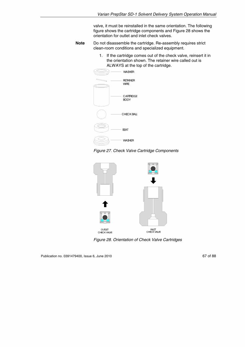
Varian PrepStar SD-1 Solvent Delivery System Operation Manual
Publication no. 0391479400, Issue 6, June 2010 67 of 88
valve, it must be reinstalled in the same orientation. The following figure shows the cartridge components and Figure 28 shows the orientation for outlet and inlet check valves.
Note Do not disassemble the cartridge. Re-assembly requires strict clean-room conditions and specialized equipment.
1. If the cartridge comes out of the check valve, reinsert it in the orientation shown. The retainer wire called out is ALWAYS at the top of the cartridge.
WASHER
RETAINERWIRE
CARTRIDGEBODY
CHECK BALL
SEAT
WASHER
Figure 27. Check Valve Cartridge Components
OUTLETCHECKVALVE
INLETCHECKVALVE
Figure 28. Orientation of Check Valve Cartridges
Varian PrepStar SD-1 Solvent Delivery System Operation Manual
68 of 88 Publication no. 0391479400, Issue 6, June 2010
Note the difference between outlet and inlet check valves. The outlet check valve housing is smaller and threads into the top of the liquid head. The cartridge must be in the check valve housing as shown in Figure 28. The check ball must be above the seat in both types of check valve housing so that it will seat by gravity.
• Before installation: The check ball retainer wire should be visible at the top of the cartridge.
• After installation – Outlet check valve: The wire cannot be seen when the cartridge is correctly installed in the outlet check valve.
• After installation - Inlet check valve: The wire can be seen when the cartridge is correctly installed into the inlet check valve.
2. Push the cartridge into place into the check valve housing.
5.5.4 Replacing the Check Valve 1. Carefully thread the replacement check valve into the liquid
head. The smaller outlet check valve fits at the top of the liquid head, and the larger inlet check valve fits at the bottom of the liquid head. Tighten each check valve finger-tight for now.
2. Connect the inlet and outlet fittings and tighten them 1/8th turn past finger-tight.
3. Switch on the power and start the pump. Pump for a few minutes at moderate pressure and observe the check valve for leaks.
Caution! It is very important that you do not overtighten the check valves.
4. If there is a leak, tighten the check valve no more than 1/16th turn and tighten the inlet and outlet fittings 1/8 turn. Observe for leaks again. If there is still a leak from the check valve, tighten it by very small increments until the leak stops. Then finally tighten no more than 1/16th turn past the leak-point. Repeat for all check valves.
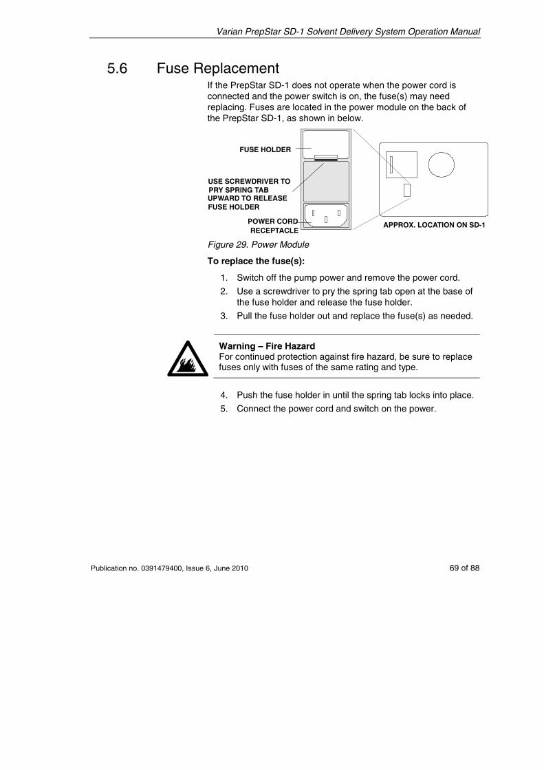
Varian PrepStar SD-1 Solvent Delivery System Operation Manual
Publication no. 0391479400, Issue 6, June 2010 69 of 88
5.6 Fuse Replacement If the PrepStar SD-1 does not operate when the power cord is connected and the power switch is on, the fuse(s) may need replacing. Fuses are located in the power module on the back of the PrepStar SD-1, as shown in below.
FUSE HOLDER
POWER CORDRECEPTACLE
APPROX. LOCATION ON SD-1
USE SCREWDRIVER TOPRY SPRING TABUPWARD TO RELEASEFUSE HOLDER
Figure 29. Power Module
To replace the fuse(s):
1. Switch off the pump power and remove the power cord.
2. Use a screwdriver to pry the spring tab open at the base of the fuse holder and release the fuse holder.
3. Pull the fuse holder out and replace the fuse(s) as needed.
Warning – Fire Hazard For continued protection against fire hazard, be sure to replace fuses only with fuses of the same rating and type.
4. Push the fuse holder in until the spring tab locks into place.
5. Connect the power cord and switch on the power.
Varian PrepStar SD-1 Solvent Delivery System Operation Manual
70 of 88 Publication no. 0391479400, Issue 6, June 2010
5.7 Troubleshooting Troubleshooting an HPLC system requires a methodical approach to be effective. To correct any given problem you have proceed step-by-step, eliminating each variable in turn before moving to the next. Some problems have more than one cause, and can be difficult to locate and correct. The following guide lists some common pump and HPLC system symptoms, with possible causes and suggested corrective actions. In most cases, you will be able to correct the problem; however, sometimes the symptom will remain after you have tried the corrective action. For assistance contact your local Varian representative.
5.7.1 “Reading” the Pressure Display The sensitivity of the pressure display is within 68.9 kPa (10 psi). The pressure display can be used as a diagnostic tool to identify the differences between the following similar symptoms:
• Bubbles in the solvent
• Sticking check valve
Both will cause erratic pressure readings.
If you notice pressure fluctuations from zero to several hundred psi when the HPLC system is operating at normal pressure, there is probably a bubble in the liquid head.
To clear a bubble, operate the pump at moderate flow (10% of maximum) with the system pressurized. Loosen the outlet tee fitting (shown below) just enough to make the fitting leak.
Warning – Chemical Hazard Personal injury may occur. Always wear appropriate safety clothing and equipment when working with solvents and strong acids.
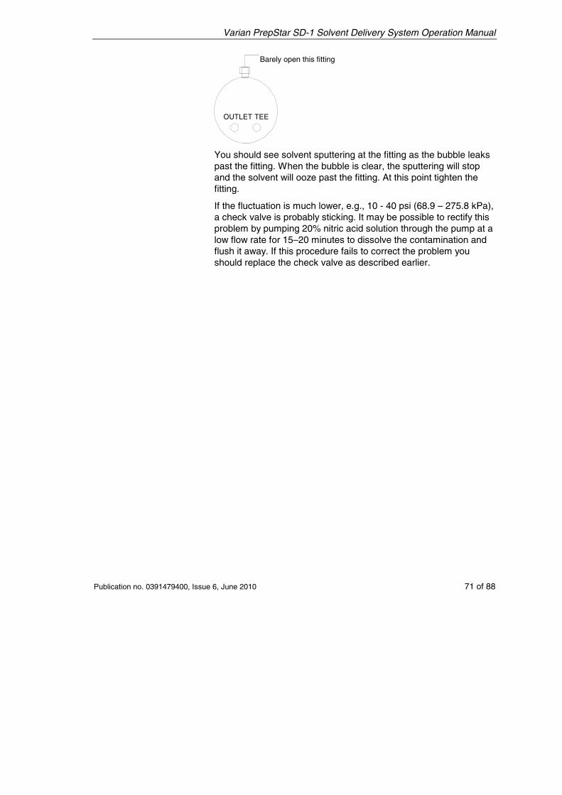
Varian PrepStar SD-1 Solvent Delivery System Operation Manual
Publication no. 0391479400, Issue 6, June 2010 71 of 88
OUTLET TEE
CRACK THIS FITTING
You should see solvent sputtering at the fitting as the bubble leaks past the fitting. When the bubble is clear, the sputtering will stop and the solvent will ooze past the fitting. At this point tighten the fitting.
If the fluctuation is much lower, e.g., 10 - 40 psi (68.9 – 275.8 kPa), a check valve is probably sticking. It may be possible to rectify this problem by pumping 20% nitric acid solution through the pump at a low flow rate for 15–20 minutes to dissolve the contamination and flush it away. If this procedure fails to correct the problem you should replace the check valve as described earlier.
Barely open this fitting
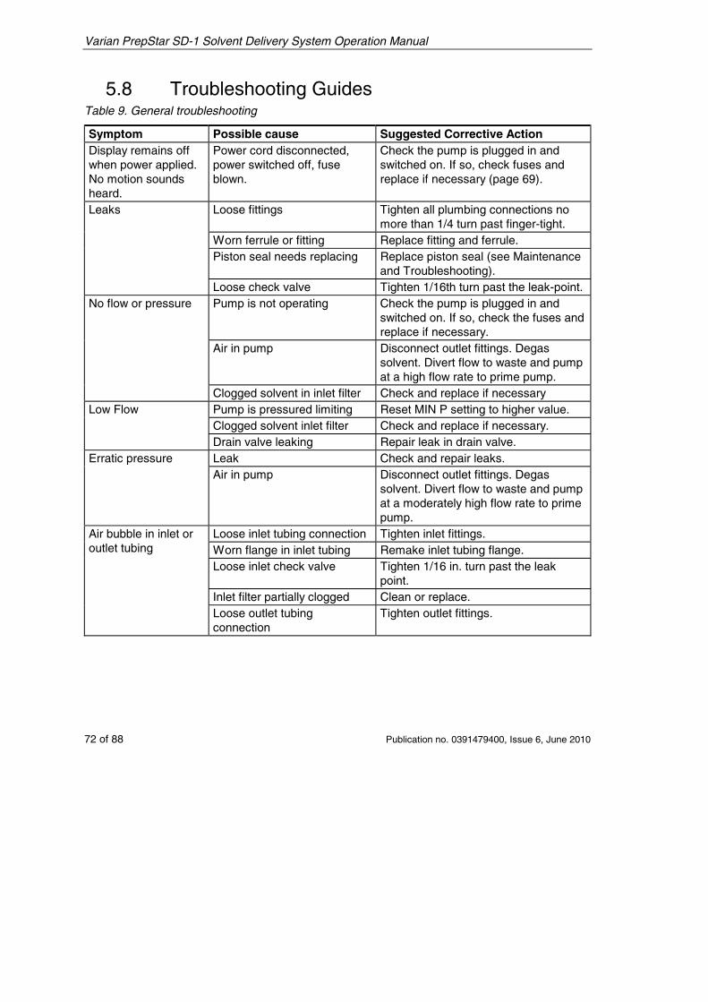
Varian PrepStar SD-1 Solvent Delivery System Operation Manual
72 of 88 Publication no. 0391479400, Issue 6, June 2010
5.8 Troubleshooting Guides Table 9. General troubleshooting
Symptom Possible cause Suggested Corrective Action Display remains off when power applied. No motion sounds heard.
Power cord disconnected, power switched off, fuse blown.
Check the pump is plugged in and switched on. If so, check fuses and replace if necessary (page 69).
Leaks Loose fittings Tighten all plumbing connections no more than 1/4 turn past finger-tight.
Worn ferrule or fitting Replace fitting and ferrule. Piston seal needs replacing Replace piston seal (see Maintenance
and Troubleshooting). Loose check valve Tighten 1/16th turn past the leak-point.
No flow or pressure Pump is not operating
Check the pump is plugged in and switched on. If so, check the fuses and replace if necessary.
Air in pump Disconnect outlet fittings. Degas solvent. Divert flow to waste and pump at a high flow rate to prime pump.
Clogged solvent in inlet filter Check and replace if necessary Low Flow Pump is pressured limiting Reset MIN P setting to higher value.
Clogged solvent inlet filter Check and replace if necessary. Drain valve leaking Repair leak in drain valve.
Erratic pressure Leak Check and repair leaks. Air in pump Disconnect outlet fittings. Degas
solvent. Divert flow to waste and pump at a moderately high flow rate to prime pump.
Air bubble in inlet or outlet tubing
Loose inlet tubing connection Tighten inlet fittings. Worn flange in inlet tubing Remake inlet tubing flange. Loose inlet check valve Tighten 1/16 in. turn past the leak
point. Inlet filter partially clogged Clean or replace. Loose outlet tubing connection
Tighten outlet fittings.
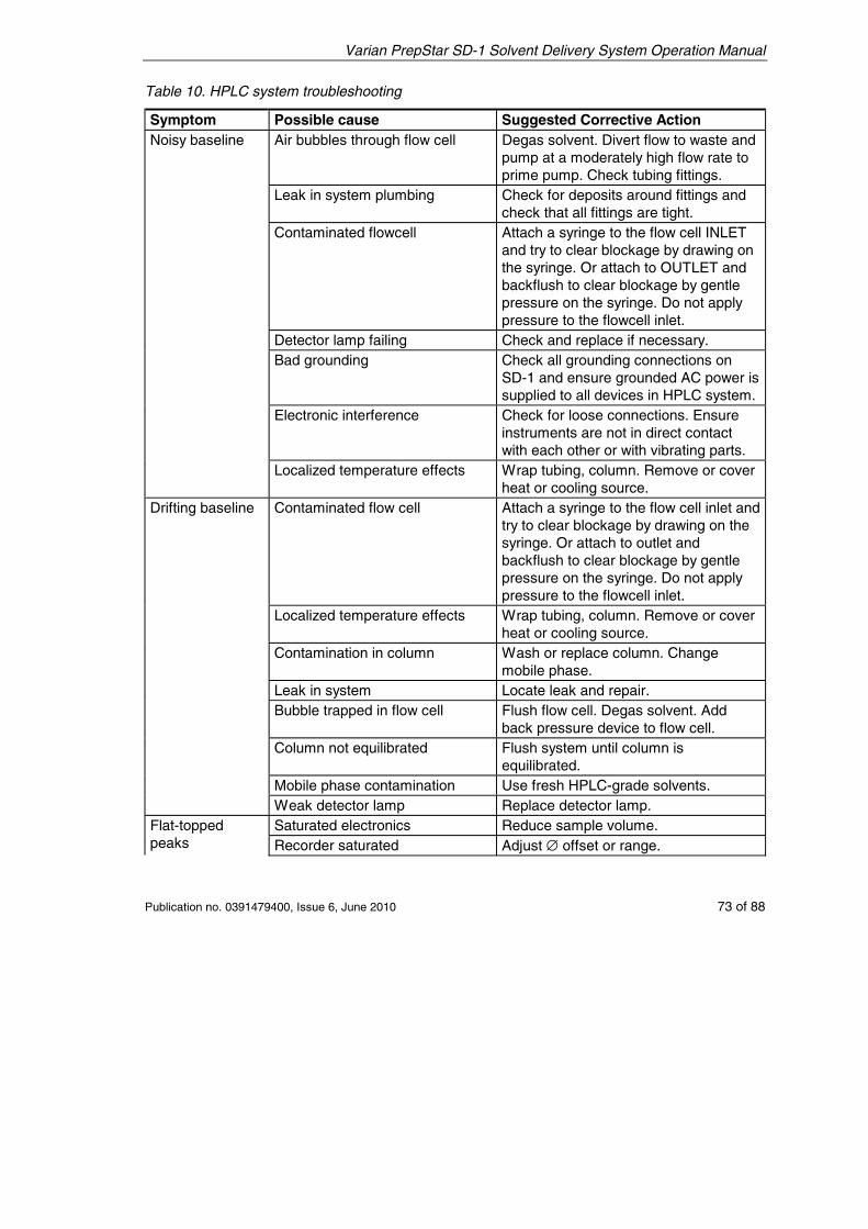
Varian PrepStar SD-1 Solvent Delivery System Operation Manual
Publication no. 0391479400, Issue 6, June 2010 73 of 88
Table 10. HPLC system troubleshooting
Symptom Possible cause Suggested Corrective Action Noisy baseline Air bubbles through flow cell Degas solvent. Divert flow to waste and
pump at a moderately high flow rate to prime pump. Check tubing fittings.
Leak in system plumbing Check for deposits around fittings and check that all fittings are tight.
Contaminated flowcell Attach a syringe to the flow cell INLET and try to clear blockage by drawing on the syringe. Or attach to OUTLET and backflush to clear blockage by gentle pressure on the syringe. Do not apply pressure to the flowcell inlet.
Detector lamp failing Check and replace if necessary. Bad grounding Check all grounding connections on
SD-1 and ensure grounded AC power is supplied to all devices in HPLC system.
Electronic interference Check for loose connections. Ensure instruments are not in direct contact with each other or with vibrating parts.
Localized temperature effects Wrap tubing, column. Remove or cover heat or cooling source.
Drifting baseline Contaminated flow cell Attach a syringe to the flow cell inlet and try to clear blockage by drawing on the syringe. Or attach to outlet and backflush to clear blockage by gentle pressure on the syringe. Do not apply pressure to the flowcell inlet.
Localized temperature effects Wrap tubing, column. Remove or cover heat or cooling source.
Contamination in column Wash or replace column. Change mobile phase.
Leak in system Locate leak and repair. Bubble trapped in flow cell Flush flow cell. Degas solvent. Add
back pressure device to flow cell. Column not equilibrated Flush system until column is
equilibrated. Mobile phase contamination Use fresh HPLC-grade solvents. Weak detector lamp Replace detector lamp.
Flat-topped peaks
Saturated electronics Reduce sample volume. Recorder saturated Adjust ∅ offset or range.
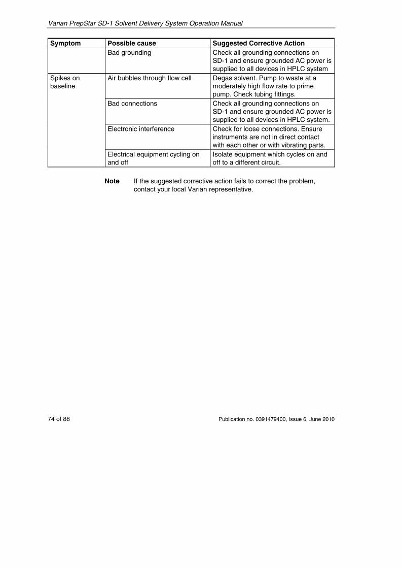
Varian PrepStar SD-1 Solvent Delivery System Operation Manual
74 of 88 Publication no. 0391479400, Issue 6, June 2010
Symptom Possible cause Suggested Corrective Action Bad grounding Check all grounding connections on
SD-1 and ensure grounded AC power is supplied to all devices in HPLC system
Spikes on baseline
Air bubbles through flow cell Degas solvent. Pump to waste at a moderately high flow rate to prime pump. Check tubing fittings.
Bad connections Check all grounding connections on SD-1 and ensure grounded AC power is supplied to all devices in HPLC system.
Electronic interference Check for loose connections. Ensure instruments are not in direct contact with each other or with vibrating parts.
Electrical equipment cycling on and off
Isolate equipment which cycles on and off to a different circuit.
Note If the suggested corrective action fails to correct the problem,
contact your local Varian representative.
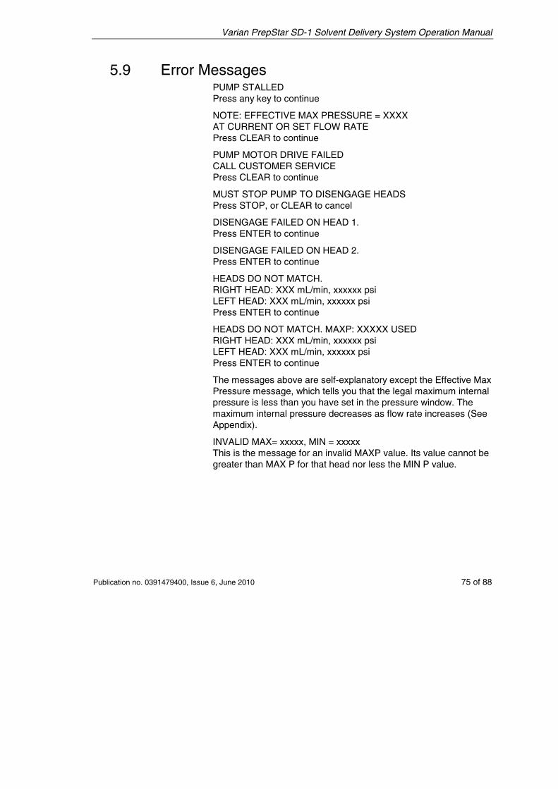
Varian PrepStar SD-1 Solvent Delivery System Operation Manual
Publication no. 0391479400, Issue 6, June 2010 75 of 88
5.9 Error Messages PUMP STALLED Press any key to continue
NOTE: EFFECTIVE MAX PRESSURE = XXXX AT CURRENT OR SET FLOW RATE Press CLEAR to continue
PUMP MOTOR DRIVE FAILED CALL CUSTOMER SERVICE Press CLEAR to continue
MUST STOP PUMP TO DISENGAGE HEADS Press STOP, or CLEAR to cancel
DISENGAGE FAILED ON HEAD 1. Press ENTER to continue
DISENGAGE FAILED ON HEAD 2. Press ENTER to continue
HEADS DO NOT MATCH. RIGHT HEAD: XXX mL/min, xxxxxx psi LEFT HEAD: XXX mL/min, xxxxxx psi Press ENTER to continue
HEADS DO NOT MATCH. MAXP: XXXXX USED RIGHT HEAD: XXX mL/min, xxxxxx psi LEFT HEAD: XXX mL/min, xxxxxx psi Press ENTER to continue
The messages above are self-explanatory except the Effective Max Pressure message, which tells you that the legal maximum internal pressure is less than you have set in the pressure window. The maximum internal pressure decreases as flow rate increases (See Appendix).
INVALID MAX= xxxxx, MIN = xxxxx This is the message for an invalid MAXP value. Its value cannot be greater than MAX P for that head nor less the MIN P value.

Varian PrepStar SD-1 Solvent Delivery System Operation Manual
76 of 88 Publication no. 0391479400, Issue 6, June 2010
This page is intentionally left blank.
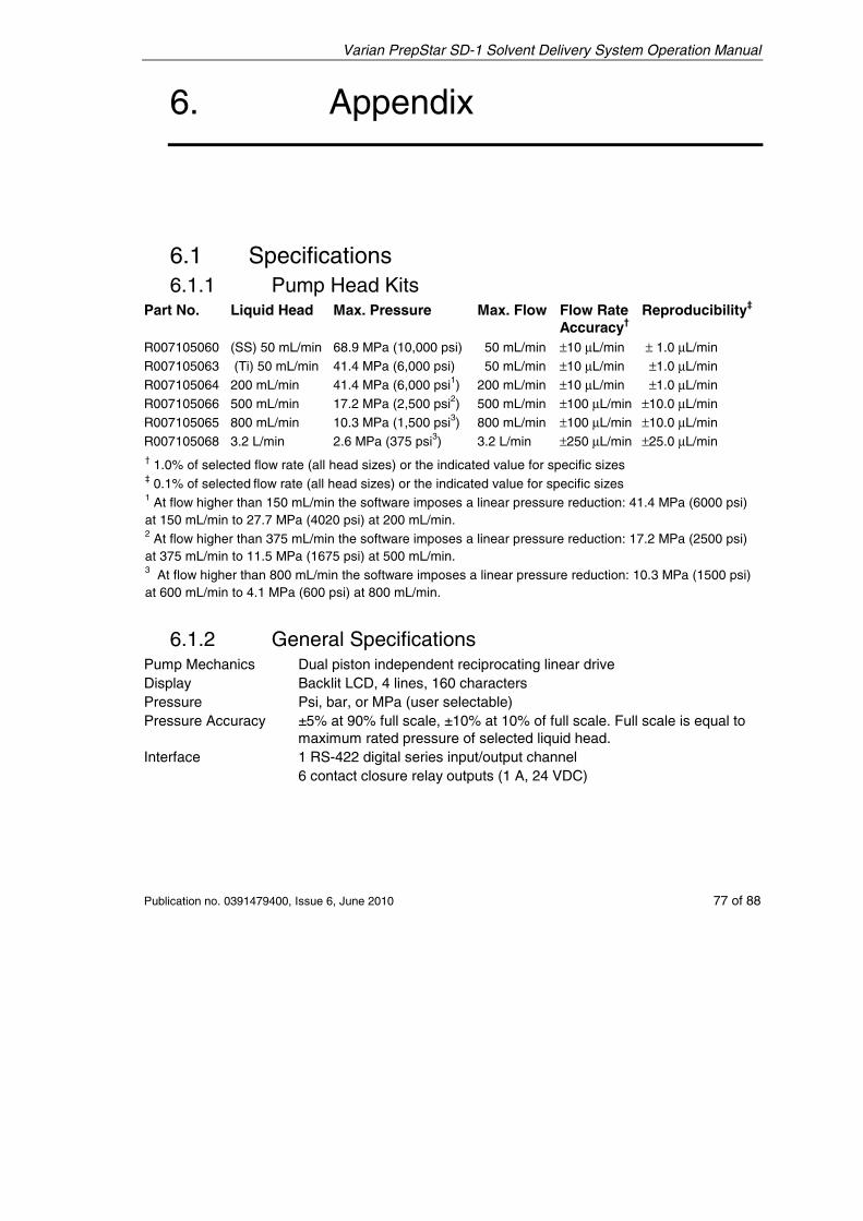
Varian PrepStar SD-1 Solvent Delivery System Operation Manual
Publication no. 0391479400, Issue 6, June 2010 77 of 88
6. Appendix
6.1 Specifications 6.1.1 Pump Head Kits
Part No. Liquid Head Max. Pressure Max. Flow Flow Rate Accuracy†
Reproducibility‡
R007105060 (SS) 50 mL/min 68.9 MPa (10,000 psi) 50 mL/min ±10 μL/min ± 1.0 μL/min R007105063 (Ti) 50 mL/min 41.4 MPa (6,000 psi) 50 mL/min ±10 μL/min ±1.0 μL/min R007105064 200 mL/min 41.4 MPa (6,000 psi1) 200 mL/min ±10 μL/min ±1.0 μL/min R007105066 500 mL/min 17.2 MPa (2,500 psi2) 500 mL/min ±100 μL/min ±10.0 μL/min R007105065 800 mL/min 10.3 MPa (1,500 psi3) 800 mL/min ±100 μL/min ±10.0 μL/min R007105068 3.2 L/min 2.6 MPa (375 psi3) 3.2 L/min ±250 μL/min ±25.0 μL/min † 1.0% of selected flow rate (all head sizes) or the indicated value for specific sizes ‡ 0.1% of selected flow rate (all head sizes) or the indicated value for specific sizes 1 At flow higher than 150 mL/min the software imposes a linear pressure reduction: 41.4 MPa (6000 psi) at 150 mL/min to 27.7 MPa (4020 psi) at 200 mL/min. 2 At flow higher than 375 mL/min the software imposes a linear pressure reduction: 17.2 MPa (2500 psi) at 375 mL/min to 11.5 MPa (1675 psi) at 500 mL/min. 3 At flow higher than 800 mL/min the software imposes a linear pressure reduction: 10.3 MPa (1500 psi) at 600 mL/min to 4.1 MPa (600 psi) at 800 mL/min.
6.1.2 General Specifications Pump Mechanics Dual piston independent reciprocating linear drive Display Backlit LCD, 4 lines, 160 characters Pressure Psi, bar, or MPa (user selectable) Pressure Accuracy ±5% at 90% full scale, ±10% at 10% of full scale. Full scale is equal to
maximum rated pressure of selected liquid head. Interface 1 RS-422 digital series input/output channel 6 contact closure relay outputs (1 A, 24 VDC)
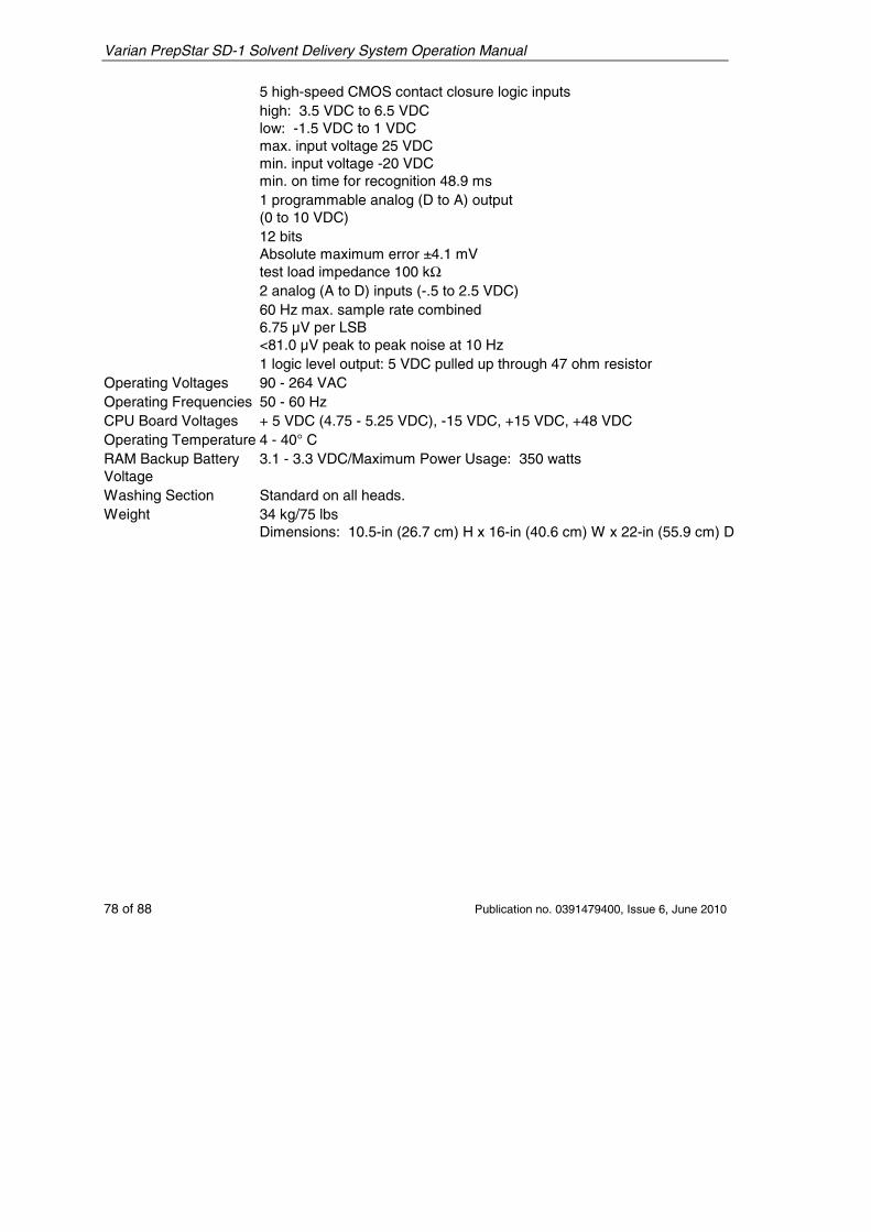
Varian PrepStar SD-1 Solvent Delivery System Operation Manual
78 of 88 Publication no. 0391479400, Issue 6, June 2010
5 high-speed CMOS contact closure logic inputs high: 3.5 VDC to 6.5 VDC low: -1.5 VDC to 1 VDC max. input voltage 25 VDC min. input voltage -20 VDC min. on time for recognition 48.9 ms
1 programmable analog (D to A) output (0 to 10 VDC) 12 bits Absolute maximum error ±4.1 mV test load impedance 100 kΩ
2 analog (A to D) inputs (-.5 to 2.5 VDC) 60 Hz max. sample rate combined 6.75 µV per LSB <81.0 µV peak to peak noise at 10 Hz
1 logic level output: 5 VDC pulled up through 47 ohm resistor Operating Voltages 90 - 264 VAC Operating Frequencies 50 - 60 Hz CPU Board Voltages + 5 VDC (4.75 - 5.25 VDC), -15 VDC, +15 VDC, +48 VDC Operating Temperature 4 - 40° C RAM Backup Battery Voltage
3.1 - 3.3 VDC/Maximum Power Usage: 350 watts
Washing Section Standard on all heads. Weight 34 kg/75 lbs
Dimensions: 10.5-in (26.7 cm) H x 16-in (40.6 cm) W x 22-in (55.9 cm) D
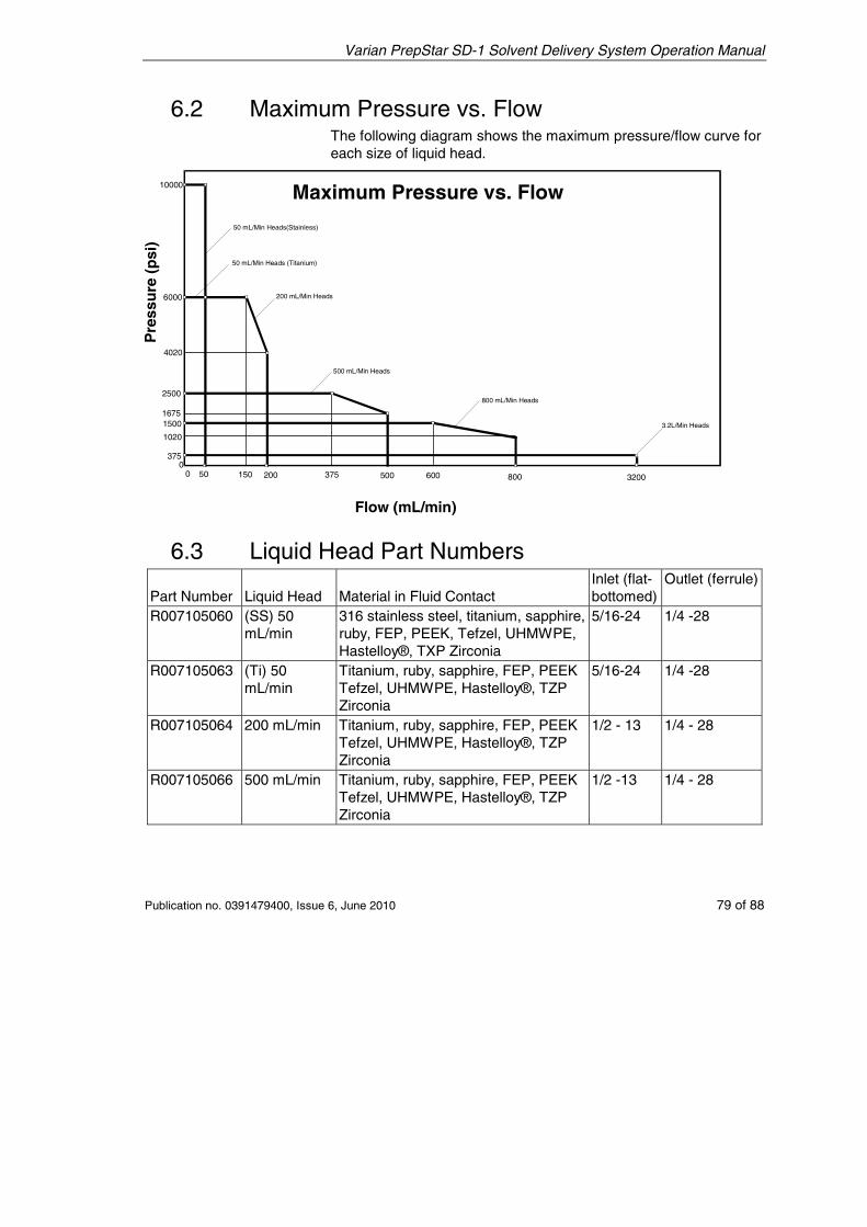
Varian PrepStar SD-1 Solvent Delivery System Operation Manual
Publication no. 0391479400, Issue 6, June 2010 79 of 88
6.2 Maximum Pressure vs. Flow The following diagram shows the maximum pressure/flow curve for each size of liquid head.
Maximum Pressure vs. Flow
375
1020
15001675
2500
4020
6000
10000
Pr e
ssu
re (
psi
)
00 50 150 200 375 500 600 800 3200
800 mL/Min Heads
3.2L/Min Heads
500 mL/Min Heads
50 mL/Min Heads (Titanium)
50 mL/Min Heads(Stainless)
200 mL/Min Heads
Flow (mL/min)
6.3 Liquid Head Part Numbers Part Number
Liquid Head
Material in Fluid Contact
Inlet (flat-bottomed)
Outlet (ferrule)
R007105060 (SS) 50 mL/min
316 stainless steel, titanium, sapphire, ruby, FEP, PEEK, Tefzel, UHMWPE, Hastelloy®, TXP Zirconia
5/16-24 1/4 -28
R007105063 (Ti) 50 mL/min
Titanium, ruby, sapphire, FEP, PEEK Tefzel, UHMWPE, Hastelloy®, TZP Zirconia
5/16-24 1/4 -28
R007105064 200 mL/min Titanium, ruby, sapphire, FEP, PEEK Tefzel, UHMWPE, Hastelloy®, TZP Zirconia
1/2 - 13 1/4 - 28
R007105066 500 mL/min Titanium, ruby, sapphire, FEP, PEEK Tefzel, UHMWPE, Hastelloy®, TZP Zirconia
1/2 -13 1/4 - 28
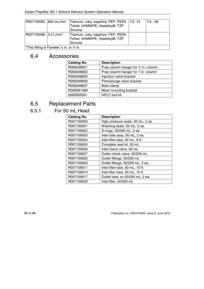
Varian PrepStar SD-1 Solvent Delivery System Operation Manual
80 of 88 Publication no. 0391479400, Issue 6, June 2010
R007105065 800 mL/min Titanium, ruby, sapphire, FEP, PEEK Tefzel, UHMWPE, Hastelloy®, TZP Zirconia
1/2 -13 1/4 - 28
R007105066 3.2 L/min* Titanium, ruby, sapphire, FEP, PEEK Tefzel, UHMWPE, Hastelloy®, TZP Zirconia
*This fitting is Flaretek ½ in. or ¼ in.
6.4 Accessories Catalog No. Description R000048601 Prep column hanger for ½ in. column R000048602 Prep column hanger for 1 in. column R000048605 Injection valve bracket R000048606 Prime/purge valve bracket R000048607 Mast clamp R000081399 Mixer mounting bracket 0393593591 HPLC tool kit
6.5 Replacement Parts 6.5.1 For 50 mL Head
Catalog No. Description R007105650 High pressure seals, 50 mL, 2 ea. R007105651 Washing seals, 50 mL, 2 ea. R007105622 O-rings, 50/200 mL, 2 ea. R007105653 Inlet tube assy, 50 mL, 2 ea. R007105654 Inlet filter tube, 50 mL, 6 ft. R007105655 Complete seal kit, 50 mL R007105656 Inlet check valve, 50 mL R007105627 Outlet check valve, 50/200 mL R007105602 Outlet fittings, 50/200 mL R007105603 Outlet fittings, 50/200 mL, 5 ea. R007105611 Inlet filter tube, 50 mL, 10 ft. R007105614 Inlet filter tube, 50 mL, 15 ft. R007105617 Outlet tube, ss 50/200 mL, 2 ea. R007105629 Inlet filter, 50/200 mL
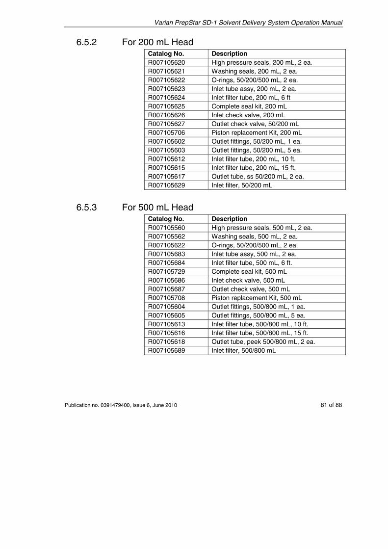
Varian PrepStar SD-1 Solvent Delivery System Operation Manual
Publication no. 0391479400, Issue 6, June 2010 81 of 88
6.5.2 For 200 mL Head Catalog No. Description R007105620 High pressure seals, 200 mL, 2 ea. R007105621 Washing seals, 200 mL, 2 ea. R007105622 O-rings, 50/200/500 mL, 2 ea. R007105623 Inlet tube assy, 200 mL, 2 ea. R007105624 Inlet filter tube, 200 mL, 6 ft R007105625 Complete seal kit, 200 mL R007105626 Inlet check valve, 200 mL R007105627 Outlet check valve, 50/200 mL R007105706 Piston replacement Kit, 200 mL R007105602 Outlet fittings, 50/200 mL, 1 ea. R007105603 Outlet fittings, 50/200 mL, 5 ea. R007105612 Inlet filter tube, 200 mL, 10 ft. R007105615 Inlet filter tube, 200 mL, 15 ft. R007105617 Outlet tube, ss 50/200 mL, 2 ea. R007105629 Inlet filter, 50/200 mL
6.5.3 For 500 mL Head Catalog No. Description R007105560 High pressure seals, 500 mL, 2 ea. R007105562 Washing seals, 500 mL, 2 ea. R007105622 O-rings, 50/200/500 mL, 2 ea. R007105683 Inlet tube assy, 500 mL, 2 ea. R007105684 Inlet filter tube, 500 mL, 6 ft. R007105729 Complete seal kit, 500 mL R007105686 Inlet check valve, 500 mL R007105687 Outlet check valve, 500 mL R007105708 Piston replacement Kit, 500 mL R007105604 Outlet fittings, 500/800 mL, 1 ea. R007105605 Outlet fittings, 500/800 mL, 5 ea. R007105613 Inlet filter tube, 500/800 mL, 10 ft. R007105616 Inlet filter tube, 500/800 mL, 15 ft. R007105618 Outlet tube, peek 500/800 mL, 2 ea. R007105689 Inlet filter, 500/800 mL
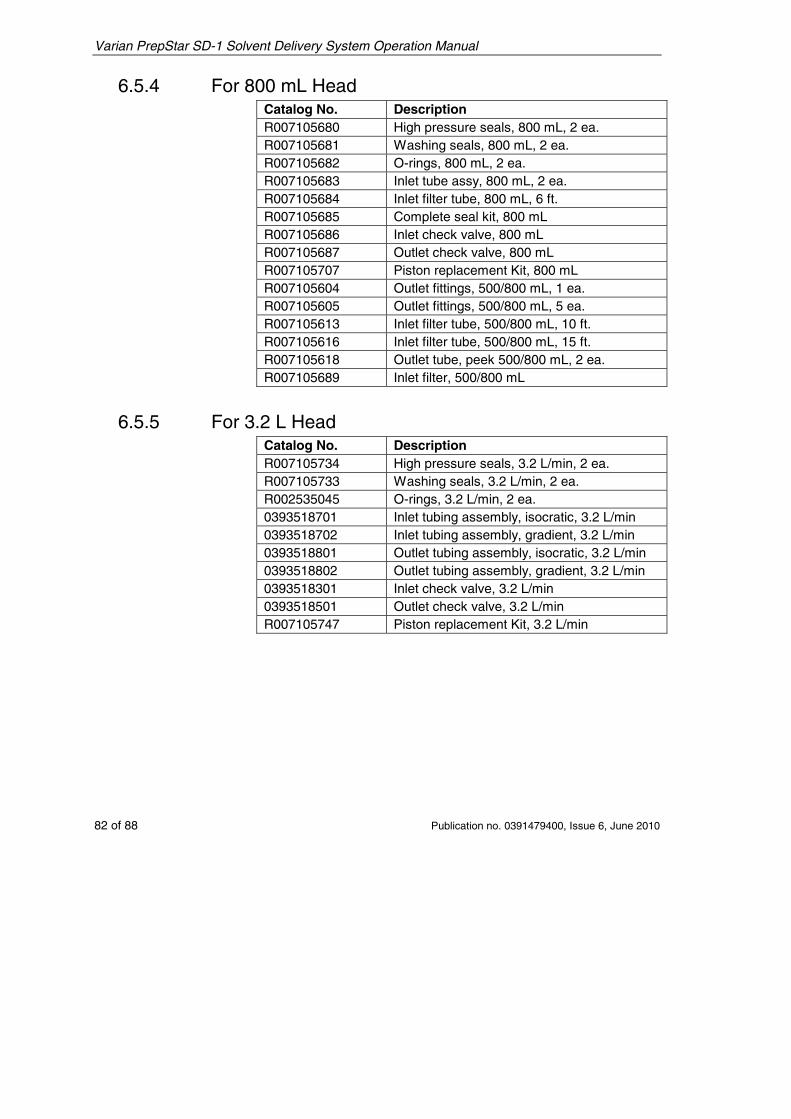
Varian PrepStar SD-1 Solvent Delivery System Operation Manual
82 of 88 Publication no. 0391479400, Issue 6, June 2010
6.5.4 For 800 mL Head Catalog No. Description R007105680 High pressure seals, 800 mL, 2 ea. R007105681 Washing seals, 800 mL, 2 ea. R007105682 O-rings, 800 mL, 2 ea. R007105683 Inlet tube assy, 800 mL, 2 ea. R007105684 Inlet filter tube, 800 mL, 6 ft. R007105685 Complete seal kit, 800 mL R007105686 Inlet check valve, 800 mL R007105687 Outlet check valve, 800 mL R007105707 Piston replacement Kit, 800 mL R007105604 Outlet fittings, 500/800 mL, 1 ea. R007105605 Outlet fittings, 500/800 mL, 5 ea. R007105613 Inlet filter tube, 500/800 mL, 10 ft. R007105616 Inlet filter tube, 500/800 mL, 15 ft. R007105618 Outlet tube, peek 500/800 mL, 2 ea. R007105689 Inlet filter, 500/800 mL
6.5.5 For 3.2 L Head Catalog No. Description R007105734 High pressure seals, 3.2 L/min, 2 ea. R007105733 Washing seals, 3.2 L/min, 2 ea. R002535045 O-rings, 3.2 L/min, 2 ea. 0393518701 Inlet tubing assembly, isocratic, 3.2 L/min 0393518702 Inlet tubing assembly, gradient, 3.2 L/min 0393518801 Outlet tubing assembly, isocratic, 3.2 L/min 0393518802 Outlet tubing assembly, gradient, 3.2 L/min 0393518301 Inlet check valve, 3.2 L/min 0393518501 Outlet check valve, 3.2 L/min R007105747 Piston replacement Kit, 3.2 L/min
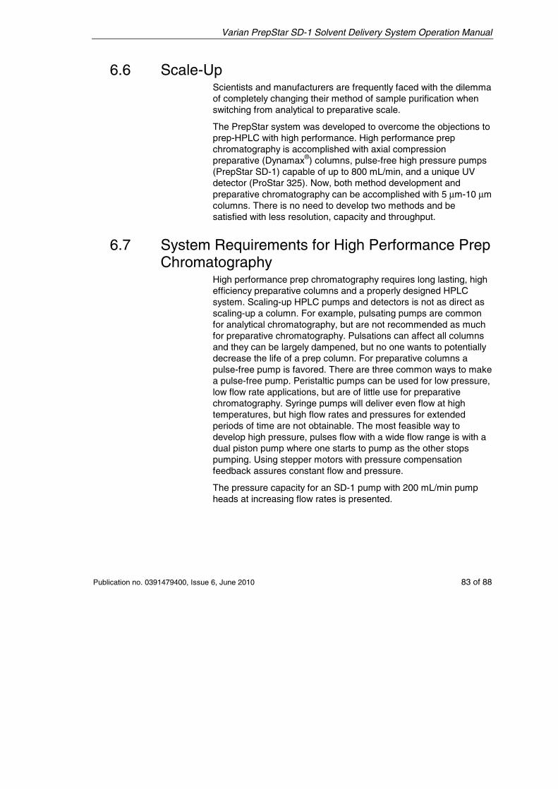
Varian PrepStar SD-1 Solvent Delivery System Operation Manual
Publication no. 0391479400, Issue 6, June 2010 83 of 88
6.6 Scale-Up Scientists and manufacturers are frequently faced with the dilemma of completely changing their method of sample purification when switching from analytical to preparative scale.
The PrepStar system was developed to overcome the objections to prep-HPLC with high performance. High performance prep chromatography is accomplished with axial compression preparative (Dynamax®) columns, pulse-free high pressure pumps (PrepStar SD-1) capable of up to 800 mL/min, and a unique UV detector (ProStar 325). Now, both method development and preparative chromatography can be accomplished with 5 μm-10 μm columns. There is no need to develop two methods and be satisfied with less resolution, capacity and throughput.
6.7 System Requirements for High Performance Prep Chromatography
High performance prep chromatography requires long lasting, high efficiency preparative columns and a properly designed HPLC system. Scaling-up HPLC pumps and detectors is not as direct as scaling-up a column. For example, pulsating pumps are common for analytical chromatography, but are not recommended as much for preparative chromatography. Pulsations can affect all columns and they can be largely dampened, but no one wants to potentially decrease the life of a prep column. For preparative columns a pulse-free pump is favored. There are three common ways to make a pulse-free pump. Peristaltic pumps can be used for low pressure, low flow rate applications, but are of little use for preparative chromatography. Syringe pumps will deliver even flow at high temperatures, but high flow rates and pressures for extended periods of time are not obtainable. The most feasible way to develop high pressure, pulses flow with a wide flow range is with a dual piston pump where one starts to pump as the other stops pumping. Using stepper motors with pressure compensation feedback assures constant flow and pressure.
The pressure capacity for an SD-1 pump with 200 mL/min pump heads at increasing flow rates is presented.
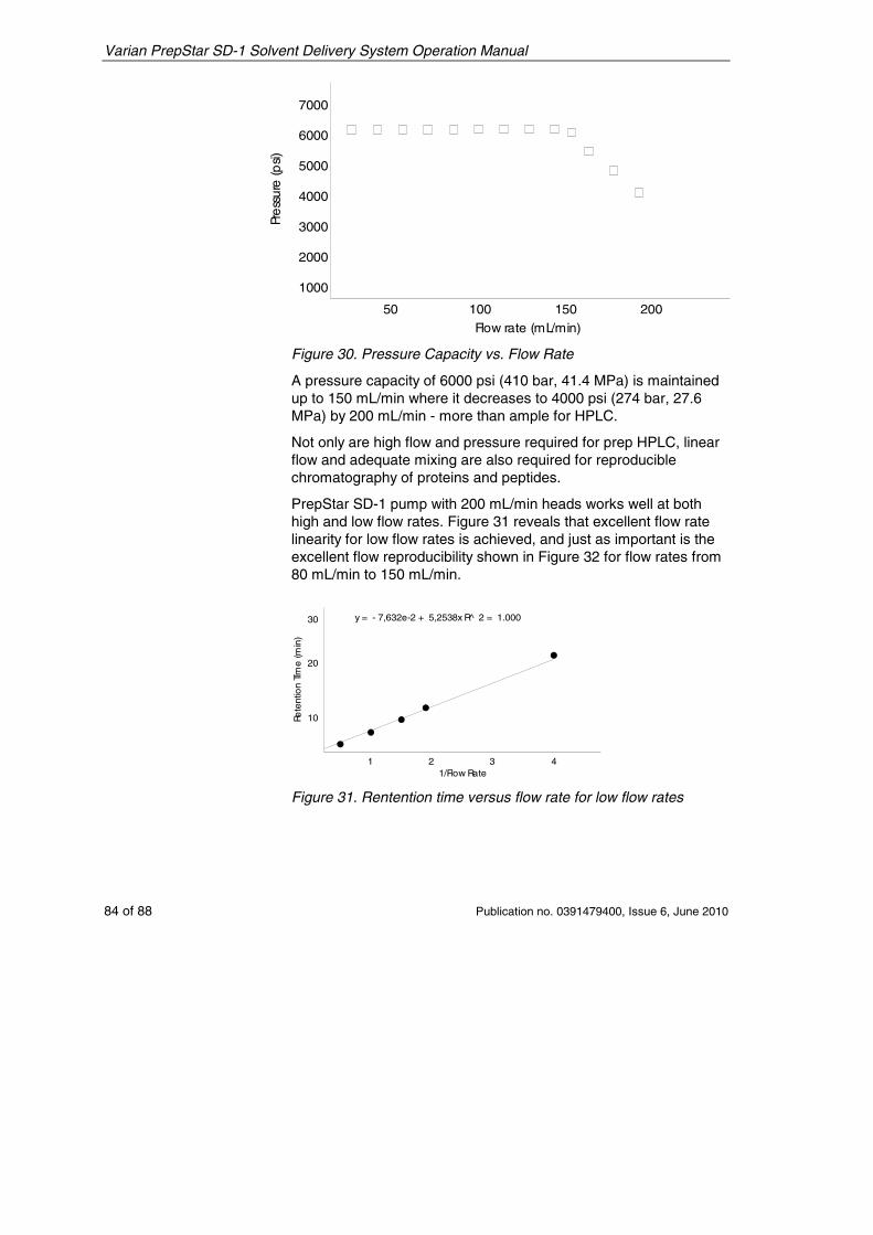
Varian PrepStar SD-1 Solvent Delivery System Operation Manual
84 of 88 Publication no. 0391479400, Issue 6, June 2010
Pre
ssur
e(p
si)
Flow rate (mL/min)
7000
6000
5000
4000
3000
2000
1000
50 100 150 200
Figure 30. Pressure Capacity vs. Flow Rate
A pressure capacity of 6000 psi (410 bar, 41.4 MPa) is maintained up to 150 mL/min where it decreases to 4000 psi (274 bar, 27.6 MPa) by 200 mL/min - more than ample for HPLC.
Not only are high flow and pressure required for prep HPLC, linear flow and adequate mixing are also required for reproducible chromatography of proteins and peptides.
PrepStar SD-1 pump with 200 mL/min heads works well at both high and low flow rates. Figure 31 reveals that excellent flow rate linearity for low flow rates is achieved, and just as important is the excellent flow reproducibility shown in Figure 32 for flow rates from 80 mL/min to 150 mL/min.
30
20
10
1 2 3 41/Flow Rate
Rete
ntio
nTIm
e(m
in)
y = - 7,632e-2 + 5,2538x R̂ 2 = 1.000
Figure 31. Rentention time versus flow rate for low flow rates
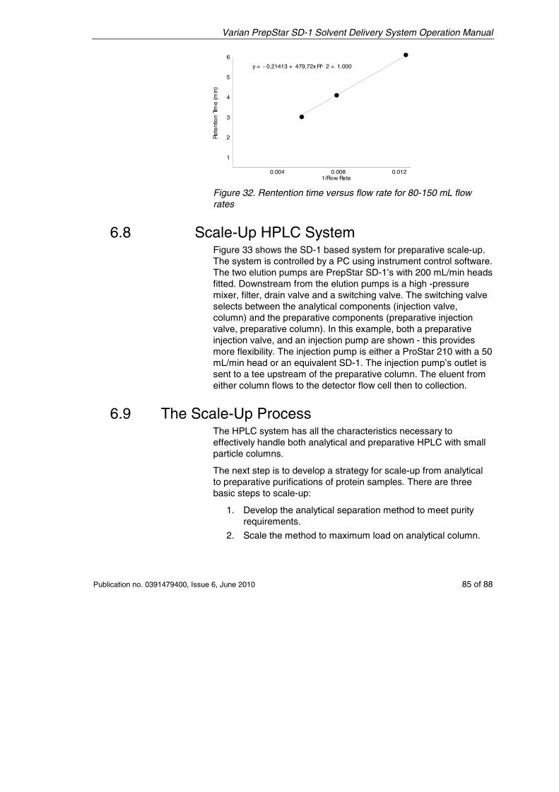
Varian PrepStar SD-1 Solvent Delivery System Operation Manual
Publication no. 0391479400, Issue 6, June 2010 85 of 88
Rete
ntio
nTim
e(m
in)
6
5
4
3
2
1
0.004 0.008 0.0121/Flow Rate
y = - 0,21413 + 479,72x R̂ 2 = 1.000
Figure 32. Rentention time versus flow rate for 80-150 mL flow rates
6.8 Scale-Up HPLC System Figure 33 shows the SD-1 based system for preparative scale-up. The system is controlled by a PC using instrument control software. The two elution pumps are PrepStar SD-1’s with 200 mL/min heads fitted. Downstream from the elution pumps is a high -pressure mixer, filter, drain valve and a switching valve. The switching valve selects between the analytical components (injection valve, column) and the preparative components (preparative injection valve, preparative column). In this example, both a preparative injection valve, and an injection pump are shown - this provides more flexibility. The injection pump is either a ProStar 210 with a 50 mL/min head or an equivalent SD-1. The injection pump’s outlet is sent to a tee upstream of the preparative column. The eluent from either column flows to the detector flow cell then to collection.
6.9 The Scale-Up Process The HPLC system has all the characteristics necessary to effectively handle both analytical and preparative HPLC with small particle columns.
The next step is to develop a strategy for scale-up from analytical to preparative purifications of protein samples. There are three basic steps to scale-up:
1. Develop the analytical separation method to meet purity requirements.
2. Scale the method to maximum load on analytical column.
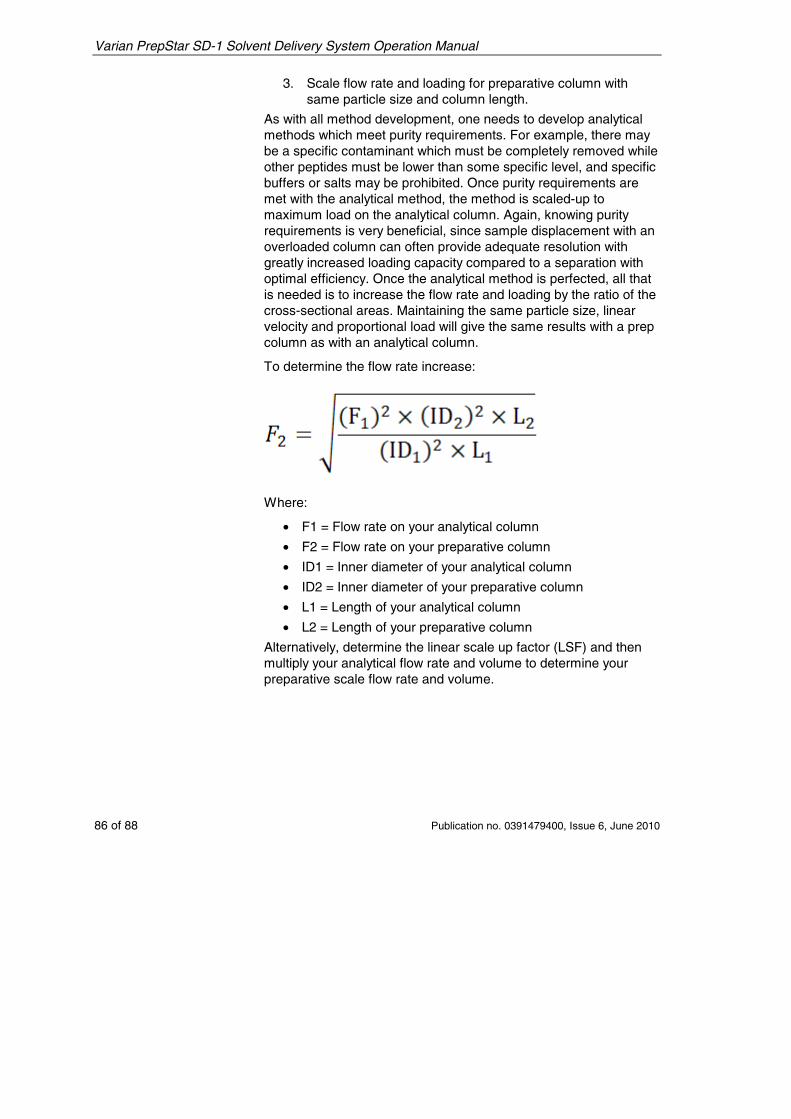
Varian PrepStar SD-1 Solvent Delivery System Operation Manual
86 of 88 Publication no. 0391479400, Issue 6, June 2010
3. Scale flow rate and loading for preparative column with same particle size and column length.
As with all method development, one needs to develop analytical methods which meet purity requirements. For example, there may be a specific contaminant which must be completely removed while other peptides must be lower than some specific level, and specific buffers or salts may be prohibited. Once purity requirements are met with the analytical method, the method is scaled-up to maximum load on the analytical column. Again, knowing purity requirements is very beneficial, since sample displacement with an overloaded column can often provide adequate resolution with greatly increased loading capacity compared to a separation with optimal efficiency. Once the analytical method is perfected, all that is needed is to increase the flow rate and loading by the ratio of the cross-sectional areas. Maintaining the same particle size, linear velocity and proportional load will give the same results with a prep column as with an analytical column.
To determine the flow rate increase:
Where:
• F1 = Flow rate on your analytical column
• F2 = Flow rate on your preparative column
• ID1 = Inner diameter of your analytical column
• ID2 = Inner diameter of your preparative column
• L1 = Length of your analytical column
• L2 = Length of your preparative column
Alternatively, determine the linear scale up factor (LSF) and then multiply your analytical flow rate and volume to determine your preparative scale flow rate and volume.
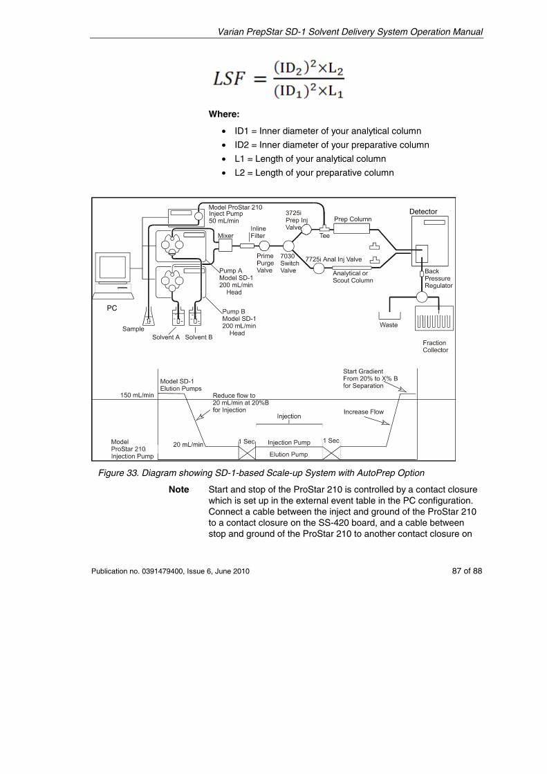
Varian PrepStar SD-1 Solvent Delivery System Operation Manual
Publication no. 0391479400, Issue 6, June 2010 87 of 88
Where:
• ID1 = Inner diameter of your analytical column
• ID2 = Inner diameter of your preparative column
• L1 = Length of your analytical column
• L2 = Length of your preparative column
Figure 33. Diagram showing SD-1-based Scale-up System with AutoPrep Option
Note Start and stop of the ProStar 210 is controlled by a contact closure which is set up in the external event table in the PC configuration. Connect a cable between the inject and ground of the ProStar 210 to a contact closure on the SS-420 board, and a cable between stop and ground of the ProStar 210 to another contact closure on
Detector
PC
Varian PrepStar SD-1 Solvent Delivery System Operation Manual
88 of 88 Publication no. 0391479400, Issue 6, June 2010
the SS-420 board. Set up the trigger of these contact closures at the appropriate time in the external event table. The ProStar 210 must not be on the bus or it will limit the maximum flow rate to the maximum allowable system flow rate of the ProStar 210.