prepstar sd-1 solvent delivery system operation manual · prepstar sd-1 solvent delivery system...
TRANSCRIPT
Varian, Inc. 2700 Mitchell Drive Walnut Creek, CA 94598-1675/usa
©Varian, Inc. 2000 - 2004 Printed in U.S.A. 03-914794-00:Rev. 3
PrepStar SD-1 Solvent Delivery System
Operation Manual

Declaration of Conformity We hereby Declare that the equipment listed below complies with the requirements of:
The Low Voltage Directive 73/23/EEC (93/68/EEC) The EMC Directive 89/336/EEC (92/31/EEC and 93/68/EEC)
Applicable Standards LVD EN 61010
EMC EN 50082-1 EN 55011 Class A
Type of Equipment: PrepStar Model: SD-1
Authorized Representative in the EU Print Name: G. A. Wassink Signed: Position: Quality Manager Date: October 16, 2001
Company Name:Address:
Varian B.V. Herculesweg 8 P.O. Box 8033 4330 EA Middelburg The Netherlands
Telephone: +31(0) 118 671 000 Fax: +31(0) 118 633 118
Manufacturer Print Name: John Mills
Signed: Position: General Manager Date: August 11, 2004
Company Name:Address:
Telephone:Fax:
Varian, Inc. 2700 Mitchell Drive Walnut Creek, California 94598 USA
925-939-2400
925-945-2168
03-914535-29:6 SPEC. 03-914411-00 1:2:3:4n


03-914451-00:4 1 of 1
Quality Systems At Varian, Inc. The ISO 9000 series standards were created in Geneva in 1987 to cut through a morass of conflicting
quality definitions. These standards define a model for quality assurance systems in product design, development, manufacturing, installation, service, and customer support. They are now the worldwide quality assurance benchmark used to gauge the strength of a company's commitment to quality, and the value of its quality systems.
Various organizations around the world, such as the British Standards Institution (BSI), provide certified, objective auditors to scrutinize quality procedures, product development, manufacturing processes, and customer satisfaction programs. No company can claim ISO 9000 series registration unless it receives a stamp of approval from the demanding quality assessors of BSI or similar accredited examining body. ISO 9000 series registration constitutes an objective third-party report to determine the level of a supplier's commitment to quality.
In 1992, Varian, Inc., Analytical Instruments became registered to the most comprehensive of the ISO 9000 series standards — ISO 9001. ISO 9001 registration means that every stage of our quality system, including product development, manufacturing, final test, shipping, and parts and supplies has been rigorously examined against the most exacting set of internationally recognized standards. It means we live up to a standard of quality that you can count on today, and into the future. Our Quality System has received ISO 9001 certification number FM21797.
The quality systems that earned us ISO 9001 registration have direct benefits for our customers:
♦ We can speed instruments to you faster than ever before. Emergency orders can be processed even faster.
♦ We fill your orders promptly and completely.
♦ We have implemented a system of continuous feedback from our customers — we are aware of your needs today and tomorrow.
♦ We have improved your productivity by cutting systems failure rates in half and speeding service response time.
♦ We have embedded continuous improvement into the fabric of our organization so that we can achieve even higher levels of quality in the future.
♦ We are embedding GLP requirements into our products and services to help you meet your regulatory compliance requirements.
ISO 9001 registration is not enough. For us, quality is defined by our customers. We are not satisfied unless you are satisfied. We are striving to understand customer needs, using independent surveys, user groups, customer advisory boards, and our “Hallmark of Quality” response program, in addition to individual face-to-face customer contact. Our products and our processes are configured to meet those needs. We know that you are seeking more than the most advanced processes and top-notch applications expertise. You want to join forces with a partner committed to delivering world-class quality, reliability, and value — on time, every time.
Our overriding aim is to be that partner.

Varian, Inc. Analytical Instrument Warranty
03-914412-00:2 1 of 1
Hardware Products All analytical instruments sold by Varian, Inc. are warranted to be free from defects in material and workmanship for the periods specified and in accordance with the terms on the face of Varian's quotation or as otherwise agreed upon in writing between Varian and the Customer. The warranty period begins on the date of shipment from Varian to the original Customer. However, where installation is paid for by the Customer or included in the purchase price, the warranty period begins upon completion of installation. If the Customer schedules installation to start later than 30 days after delivery or if such delay is caused through the Customer's inability to provide adequate facilities or utilities or through failure to comply with Varian's reasonable pre-installation instructions or through other omissions by Customer, then the warranty period starts on the 31st day from date of shipment. Moreover Varian will charge the Customer for labor and other expenses involved in making multiple or follow-up installation service calls.
Software Products Where software is provided within the frame of a license agreement concluded between the Customer and Varian, any warranty shall be strictly in accordance with the terms of such agreement.
In the absence of a license agreement and unless an alternate warranty period is agreed upon in writing between Varian and the Customer, the warranty period is as specified on the face of Varian's quotation. Varian warrants such software products, if used with and properly installed on Varian hardware or other hardware as specified by Varian to perform as described in the accompanying Operator's Manual and to be substantially free of those defects which cause failure to execute respective programming instructions; however, Varian does not warrant uninterrupted or error-free operation.
Remedies The sole and exclusive remedy under hardware warranty shall be repair of instrument malfunctions which in Varian's opinion are due or traceable to defects in original materials or workmanship or, at Varian's option, replacement of the respective defective parts, provided that Varian may as an alternative elect to refund an equitable portion of the purchase price of the instrument or accessory.
Repair or replacement under warranty does not extend the original warranty period.
Repair or replacement under warranty claims shall be made in Varian's sole discretion either by sending a Customer Support Representative to the site or by authorizing the Customer to return the defective accessory or instrument to Varian or to send it to a designated service facility. The Customer shall be responsible for loss or damage in transit and shall prepay shipping cost. Varian will return the accessory or instrument to the Customer prepaid and insured. Claims for loss or damage in transit shall be filed by the Customer. To correct software operation anomalies, Varian will issue software revisions where such revisions exist and where, in Varian's opinion, this is the most efficient remedy.
Limitation of Warranty This warranty does not cover software supplied by the Customer, equipment and software warranted by another manufacturer or replacement of expendable items and those of limited life, such as but not limited to: Filters, glassware, instrument status lamps, source lamps, septa, columns, fuses, chart paper and ink, nebulizers, flow cells, pistons, seals, fittings, valves, burners, sample tubes, probe inserts, print heads, glass lined tubing, pipe and tube fittings, variable temperature dewars, transfer lines, flexible discs, magnetic tape cassettes, electron multipliers, filaments, vacuum gaskets, seats and all parts exposed to samples and mobile phases.
This warranty shall be void in the event of accident, abuse, alteration, misuse, neglect, breakage, improper operation or maintenance, unauthorized or improper modifications or tampering, use in an unsuitable physical environment, use with a marginal power supply or use with other inadequate facilities or utilities. Reasonable care must be used to avoid hazards.
This warranty is expressly in lieu of and excludes all other express or implied warranties, including but not limited to warranties of merchantability and of fitness for particular purpose, use or application, and all other obligations or liabilities on the part of Varian, unless such other warranties, obligations or liabilities are expressly agreed to in writing by Varian.
Limitation of Remedies and Liability The remedies provided herein are the sole and exclusive remedies of the Customer. In no case will Varian be liable for incidental or consequential damages, loss of use, loss of production or any other loss incurred.

03-914603-00:10 1 of 4
Safety Information
Operating Instructions This instruction manual is provided to help you establish operating conditions which will permit safe and efficient use of your equipment. Special considerations and precautions are also described in the manual, which appear in the form of NOTES, CAUTIONS, and WARNINGS as described below. It is important that you operate your equipment in accordance with this instruction manual and any additional information which may be provided by Varian. Address any questions regarding the safe and proper use of your equipment to your local Varian office.
NOTE Information to aid you in obtaining optimal performance from your instrument.
Alerts you to situations that may cause moderate injury and/or equipment damage, and how to avoid these situations.
Alerts you to potentially hazardous situations that could result in serious injury, and how to avoid these situations.
Warning Symbol Warning Description
Hazardous voltages are present inside instrument. Disconnect from main power before removing screw-attached panels.
Hazardous chemicals may be present. Avoid contact, especially when replenishing reservoirs. Use proper eye and skin protection.
Very hot or cryogenically cold surfaces may be exposed. Use proper skin protection.
Eye damage could occur either from flying particles, chemicals, or UV radiation. Use proper eye and face protection.
The potential for fire may be present. Follow manual instructions for safe operation.
The potential for explosion may exist because of type of gas or liquid used.
Ionizing radiation source is present. Follow manual instructions for safe operation.
Keep hands and fingers away.

2 of 4 03-914603-00:10
General Safety Precautions Follow these safety practices to ensure safe equipment operation.
Perform periodic leak checks on all supply lines and pneumatic plumbing. Do not allow gas lines to become kinked or punctured. Place lines away from foot traffic
and extreme heat or cold. Store organic solvents in fireproof, vented and clearly labeled cabinets so they are easily
identified as toxic and/or flammable materials. Do not accumulate waste solvents. Dispose of such materials through a regulated disposal
program and not through municipal sewage lines.
NOTICE: This instrument has been tested per applicable requirements of EMC Directive as required to carry the European Union CE Mark. As such, this equipment may be susceptible to radiation/interference levels or frequencies which are not within the tested limits.
This instrument is designed for chromatographic analysis of appropriately prepared samples. It must be operated using appropriate gases and/or solvents and within specified maximum ranges for pressure, flows, and temperatures as described in this manual. If the equipment is used in a manner not specified by the manufacturer, the protection provided by the equipment may be impaired.
It is the responsibility of the Customer to inform Varian Customer Support Representatives if the instrument has been used for the analysis of hazardous biological, radioactive, or toxic samples, prior to any instrument service being performed or when an instrument is being returned to the Service Center for repair.
Electrical Hazards Disconnect the instrument from all power sources before removing protective panels to avoid
exposure to potentially dangerous voltages. When it is necessary to use a non-original power cord plug, make sure the replacement cord adheres
to the color coding and polarity described in the manual and all local building safety codes. Replace blown fuses with fuses of the size and rating stipulated on the fuse panel or in the manual. Replace faulty or frayed power cords immediately with the same type and rating. Make sure that voltage sources and line voltage match the value for which the instrument is wired.
Compressed Gas Cylinders Store and handle compressed gases carefully and in strict adherence to safety codes. Secure cylinders to an immovable structure or wall. Store and move cylinders in an upright, vertical position. Before transport, remove regulators
and install cylinder cap. Store cylinders in a well-ventilated area away from heat, direct sunshine, freezing
temperatures, and ignition sources. Mark cylinders clearly so there is no doubt as to their contents. Use only approved regulators and connections. Use only connector tubing that is chromatographically clean (Varian Part Number 03-918326-00)
and has a pressure rating significantly greater than the highest outlet pressure from the regulator.

03-914603-00:10 3 of 4
GC Safety Practices Exhaust System No special exhaust ducting is necessary for GC detectors installed in a well-ventilated room except when the detectors are used to test hazardous chemicals. If you do install ducting:
Use only fireproof ducting. Install a blower at the duct outlet. Locate duct intakes such that their vibration or air
movement does not effect detector operation. Check periodically for proper operation of the duct. Ensure proper ventilation in lab area.
Radioactive Source Detectors
Read carefully and comply with all NOTES, CAUTIONS, and WARNINGS in the Ni63 ECD manual.
Perform the tests for removable radioactive contamination described in the Ni63 ECD manual.
Comply with leak test schedules and procedures.
Burn Hazard Heated or cryogenically cooled zones of gas chromatographs can remain hot or cold for a considerable time after instrument power is turned off. To prevent painful burns, ensure that all heated or cooled areas have returned to room temperature or wear adequate hand protection before you touch potentially hot or cold surfaces.
LC Safety Practices High Pressure Hazard
• If a line ruptures, a relief device opens, or a valve opens accidentally under pressure, potentially hazardous high liquid pressures can be generated by the pump causing a high velocity stream of volatile and/or toxic liquids.
Wear face protection when you inject samples or perform routine maintenance.
Never open a solvent line or valve under pressure. Stop the pump first and let the pressure drop to zero.
Use shatter-proof reservoirs capable of operating at 50-60 psi.
Keep the reservoir enclosure closed when the reservoir is under pressure.
Read and adhere to all NOTES, CAUTIONS, and WARNINGS in the manual.
Flash Chromatography The operator should be familiar with the physico-chemical properties of the components of the mobile phase.
Keep solvents from direct contact with the polyurethane supply tubing as certain solvents will cause weakening and leaks with possible bursting.
All components of the system should be connected to a common power supply and common ground. This ground must be a true ground rather than a floating ground.
Non-polar solvents can develop a static charge when pumped through the system. All vessels that contain mobile phase (including tubing and collection vessels) must be grounded to dissipate static electricity.
Employ static measuring and static discharge devices (e.g., air ionizers) to safeguard against the buildup of static electricity.
Ultraviolet Radiation Liquid chromatograph detectors that use an ultraviolet light source have shielding to prevent radiation exposure to personnel.
For continued protection:
Ensure that protective lamp covers of variable and fixed wavelength detectors are in place during operation.
Do not look directly into detector fluid cells or at the UV light source. When inspecting the light source or fluid cell, always use protective eye covering such as borosilicate glass or polystyrene.
The following is a Federal Communications Commission advisory: This equipment has been tested and found to comply with the limits of a Class A computing device, pursuant to part 15 of the FCC Rules. These limits are designed to provide reasonable protection against harmful interference when the equipment is operated in a commercial environment. This equipment generates, uses, and can radiate radio frequency energy and, if not installed and used in accordance with the instruction manual, may cause harmful interference to radio communications. Operation of this equipment in a residential area is likely to cause harmful interference in which case the user will be required to correct the interference at his own expense.

4 of 4 03-914603-00:10
Spare Parts Availability It is the policy of Varian to provide operational spare parts for any instrument and major accessory for a period of five (5) years after shipment of the final production run of that instrument. Spare parts will be available after this five (5) year period but on an as available basis. Operational spare parts are defined as those individual electrical or mechanical parts that are susceptible to failure during their normal operation. Examples include relays, lamps, temperature probes, detector elements, motors, etc. Sheet metal parts, structural members or assemblies and castings, printed circuit boards, and functional modules are normally capable of being rebuilt to like-new condition throughout their useful life and therefore will be supplied only on an as available basis after the final production run of the instrument.
Service Availability Varian provides a variety of services to support its customers after warranty expiration. Repair service can be provided by attractively priced service contracts or on a time and material basis. Technical support and training can be provided by qualified personnel on both a contractual or as-needed basis.
Varian, Inc. Analytical Instruments Sales Offices For Sales or Service assistance and to order Parts and Supplies, contact your local Varian office.
Argentina Buenos Aires Tel. +54.11.4.783.5306
Australia Mulgrave, Victoria Tel. +61.3.9566.1134
Austria Vösendorf bei Wien Tel. +43.1.699.9669
Benelux Bergen Op Zoom Tel. +31.164.282.800
Brazil and Latin America (S) São Paulo Tel. +55.11.820.0444
Canada Mississauga, Ontario Tel. 800.387.2216
China Beijing Tel. +86.106209.1727
Europe Middelburg, The Netherlands Tel. +31.118.671.000
France Les Ulis Cédex Tel. +33.1.6986.3838
Germany Darmstadt Tel. +49.6151.7030
India Mumbai Tel. +91.22.857.0787/88/89
Italy Torino Tel. +39.011.997.9111
Japan Tokyo Tel. +81.3.5232.1211
Korea Seoul Tel. +82.2.345.22452
Mexico and Latin America (N) Mexico City Tel. +52.5.523.9465
Russian Federation Moscow Tel. +7.095.937.4280
Spain Madrid Tel. +34.91.472.7612
Sweden Solna Tel. +46.8.445.1620
Switzerland Varian AG Tel. +41.848.803.800
Taiwan Taipei Hsien Tel. +886.2.698.9555
United Kingdom and Ireland Walton-on-Thames Tel. +44.1932.898000
Venezuela Valencia Tel. +58.41.257.608
United States Walnut Creek, California, USA Tel. +1.800.926.3000 (GC and GC/MS)
Tel. +1.800.367.4752 (LC)
www.varianinc.com

03-914603-81:10 1 of 4
Sicherheitsinformationen
Arbeitsanleitungen Diese Arbeitsanleitung will Ihnen bei der Aufstellung solcher Arbeitsbedingungen helfen, die einen sicheren und wirkungsvollen Gebrauch Ihrer Geräte ermöglichen. Besondere Überlegungen und Vorsichtsmaßnahmen erscheinen in diesem Handbuch in Form von HINWEIS, ACHTUNG und WARNUNG, wie unten beschrieben. Es ist wichtig, daß Sie Ihr Gerät in Übereinstimmung mit dieser Arbeitsanleitung und allen möglichen zusätzlichen Informationen von Varian betreiben. Alle Fragen bezüglich Sicherheit und Handhabung Ihres Gerätes richten Sie an Ihr Varian Büro.
HINWEIS ACHTUNG WARNUNG
Eine Information, um einen optimalen Wirkungsgrad Ihres Instruments zu erzielen.
Weist auf Situationen, die zu mäßiger Beeinträchtigung und/oder zu Geräteschäden führen und auf die Vermeidung dieser Situationen hin.
Weist auf mögliche Gefahrensituationen, die zu ernsthaften Verletzungen führen können und auf die Vermeidung dieser Situationen hin.
Warnungssymbol Warnungsbeschreibung
WARNUNGELEKTRISCHERSCHLAG
Gefährliche Spannungen bestehen innerhalb des Instruments. Trennen Sie das Gerät vom Netz, bevor Sie abschraubbare Paneele entfernen.
Gefährliche Chemikalien können vorhanden sein. Vermeiden Sie jeden Kon-takt, besonders beim Auffüllen der Reservoirs. Benutzen Sie wirksamen Augen und Hautschutz.
WARNUNGVERBRENNUNGSGEFAHR
Sehr heiße oder tiefstgekühlte Oberflächen können freigelegt sein. Benutzen Sie einen wirksamen Hautschutz.
Herumfliegende Partikel, Chemikalien oder UV-Strahlung können Augenschäden verursachen. Tragen Sie deshalb einen geeigneten Schutz für Augen und Gesicht.
WARNUNGFEUERGEFAHR
Es besteht eine mögliche Feuergefahr. Beachten Sie die Vorschriften im Handbuch für eine gefahrlose Benutzung.
WARNUNGEXPLOSIONSGEFAHR
Eine mögliche Explosionsgefahr besteht infolge der benutzten Gas- oder Flüssigkeitsart.
WARNUNGSTRAHLUNGSQUELLE
Es besteht eine ionisierende Strahlungsquelle. Beachten Sie die Vorschriften im Handbuch für eine gefahrlose Benutzung.
WARNUNGBEWEGTE TEILE
Bleiben Sie mit Ihren Händen und Fingern weg.
2 of 4 03-914603-81:10
Allgemeine Sicherheitsmaßnahmen Befolgen Sie diese Sicherheitspraktiken für eine gefahrlose Gerätebenutzung.
Prüfen Sie regelmäßig alle Versorgungs und Pneumatikleitungen auf Lecks. Gasleitungen dürfen nicht geknickt oder angestochen werden. Verlegen Sie die Leitungen außer-
halb von Laufwegen und abseits von extremer Hitze oder Kälte. Lagern Sie organische Lösungsmittel in feuerfesten, belüfteten und eindeutig bezeichneten
Schränken, damit sie leicht als toxische und/oder brennbare Materialien erkannt werden. Sammeln Sie keine Lösungsmittelabfälle. Entsorgen Sie solche Materialien über ein geregeltes Ent-
sorgungsprogramm und nicht über die öffentlichen Abwasserleitungen.
HINWEIS: Dies Instrument wurde nach den zutreffenden Vorschriften der EMC Direktive getestet, die zum Führen des CE Zeichens der Europäischen Union berechtigen. Dieses Gerät kann an sich auf Strahlungs-/Störpegel oder Frequenzen außerhalb der getesteten Grenzen reagieren.
WARNUNG
Dies Instrument ist für chromatographische Analysen entsprechend präparierter Proben ge-dacht. Es muß mit geeigneten Gasen und/oder Lösungsmitteln und innerhalb der im Handbuch spezifizierten maximalen Werte für Druck, Flüsse und Temperaturen betrieben werden.
WARNUNG
Der Kunde ist vor der Durchführung irgendeines Geräteservices verpflichtet den Varian Kundendienstvertreter zu informieren, wenn das Instrument für Analysen gefährlicher biologischer, radioaktiver oder toxischer Proben benutzt worden ist.
Elektrische Gefahren Lösen Sie das Instrument von allen Stromquellen, bevor Sie Schutzpaneele entfernen, damit Sie nicht mit
potentiell gefährlichen Spannungen in Berührung kommen.
Wenn ein Nicht-Original Netzkabelstecker benutzt werden muß, muß das Austauschkabel die im Handbuch beschriebene Farbcodierung und Polarität beibehalten und alle örtlichen Sicherheitsvorschriften erfüllen.
Ersetzen Sie durchgebrannte Sicherungen nur mit Sicherungen der Werte, die am Sicherungspaneel oder im Handbuch angegeben sind.
Ersetzen Sie fehlerhafte oder durchgescheuerte Netzkabel sofort durch Kabel gleicher Art.
Sorgen Sie dafür, daß Spannungsquellen und die Netzspannung den gleichen Wert haben, für den das In-strument verdrahtet ist.
Gasdruckflaschen Lagern und handhaben Sie komprimierte Gase vorsichtig und in strikter Einhaltung der
Sicherheitsvorschriften.
Befestigen Sie die Gasflaschen an feststehenden Aufbauten oder an Wänden.
Lagern und transportieren Sie Gasflaschen in aufrechter Stellung. Druckregler zuvor abnehmen.
Lagern Sie Gasflaschen in gut durchlüfteten Räumen, weit genug weg von Heizungen, direktem Sonnenschein, Frosttemperaturen und Entzündungszonen.
Kennzeichnen Sie die Flaschen so eindeutig, daß kein Zweifel über deren Inhalt bestehen kann.
Benutzen Sie nur geprüfte Druckminderer und Verbindungsstücke.
Benutzen Sie nur chromatographisch reines Verbindungsrohr (Varian Part Number 03-918326-00), das wesentlich höheren Druck als den höchsten Ausgangsdruck des Druckminderers aushält.

03-914603-81:10 3 of 4
GC Sicherheitspraktiken Abgassystem Für GC Detektoren, die in einem gut durchlüfteten Raum installiert sind, ist keine spezielle Abgasführung erforderlich, außer wenn die Detektoren zum Testen gefährlicher Chemikalien benutzt werden. Wenn Sie eine Abgasführung installieren:
Benutzen Sie nur feuerfeste Führungen. Installieren Sie ein Gebläse am Ausgang. Ordnen Sie die Ansaugöffnung so an, daß ihre Er-
schütterungen oder Luftströmungen nicht die De-tektorfunktion beeinträchtigen.
Prüfen Sie regelmäßig die einwandfreie Arbeits-weise der Abgasführung.
Sorgen Sie für gute Entlüftung im Laborbereich.
Radioaktive Detektoren Lesen Sie sorgfältig und befolgen Sie alle
HINWEISE, ACHTUNGEN und WARNUNGEN im Ni63 ECD Handbuch.
Führen Sie die Tests für zu beseitigende radioak-tive Kontamination durch, die im Ni63 ECD Hand-buch beschrieben sind.
Erfüllen Sie die Zeitpläne und Verfahren zur Di-chtigkeitsprüfung.
Verbrennungsgefahr Beheizte oder tieftemperaturgekühlte Zonen des Gas-chromatographen können beträchtlich lange heiß oder kalt bleiben, nachdem das Instrument bereits ab-geschaltet ist. Zur Vermeidung schmerzhafter Verbren-nungen müssen Sie darauf achten, daß alle beheizten oder gekühlten Zonen auf Raumtemperatur zurück-gegangen sind oder Sie müssen ausreichenden Hand-schutz benutzen, bevor Sie möglicherweise heiße oder kalte Oberflächen berühren.
LC Sicherheitspraktiken Gefahr durch hohen Druck Wenn eine Leitung bricht, eine Entlüftungseinheit sich öffnet oder ein Ventil sich unbeabsichtigt unter Druck öffnet, kann durch die Pumpe möglicherweise ein ge-fährlich hoher Flüssigkeitsdruck entstehen, der einen Strahl flüchtiger und/oder toxischer Flüssigkeiten von hoher Stömungsgeschwindigkeit verursacht.
Tragen Sie einen Gesichtsschutz, wenn Sie Proben injizieren oder Routinewartungen durchführen.
Öffnen Sie niemals eine unter Druck stehende Lösungsmittelleitung oder ein Ventil. Halten Sie zuerst die Pumpe an und lassen Sie den Druck auf Null abfallen.
Benutzen Sie splittersichere Reservoirs, die für einen Druck von 3,4 bis 4,1 bar ausgelegt sind.
Halten Sie die Reservoirverkleidung geschlossen, wenn die Reservoirs unter Druck stehen.
Lesen Sie und befolgen Sie alle HINWEISE, ACHTUNGEN und WARNUNGEN im Handbuch.
Blitzlicht-Chromatographie Der Bediener sollte mit den physikalisch-chemischen Eigenschaften der Komponenten vertraut sein, aus denen sich die mobile Phase zusammensetzt.
Vermeiden Sie direkten Kontakt der Lösungsmittel mit den Zuführungsleitungen aus Polyurethan, da einige Lösungsmittel das Material der Leitungen schwächen und damit Undichtigkeiten oder Brüche hervorrufen können.
Alle Systemkomponenten sollten an der gleichen Netzstromquelle und einer gemeinsamen Erdung angeschlossen sein. Dabei muss es sich um eine echte, nicht um eine schwebende Erdung handeln.
Nicht-polare Lösungsmittel können sich beim Pumpen durch das System statisch aufladen. Alle Gefäße, die mobile Phase enthalten (einschließlich Leitungen und Sammelgefäße), müssen zur Ableitung elektro-statischer Aufladungen geerdet sein.
Setzen Sie Geräte zur Messung und Ableitung elektrostatischer Aufladungen (z.B. Geräte zur Luftionisierung) als Maßnahmen gegen den Aufbau statischer Elektrizität ein.
Ultraviolette Strahlung Detektoren in Liquidchromatographen, die eine ultraviolette Lichtquelle benutzen, besitzen eine Abschirmung, die das Bedienungspersonal gegen Abstrahlungen schützt. Zum ständigen Schutz:
Achten Sie darauf, daß die schützende Lampenab-deckung der Detektoren mit variablen und festen Wellenlängen während des Betriebs an ihrem Platz ist.
Schauen Sie nicht direkt in die Flüssigkeitszellen im Detektor oder in die UV Lampe. Zum In-spizieren der Lichtquelle oder der Flüssigkeitszelle benutzen Sie immer einen wirksamen Augenschutz, wie er durch Borsilikatglas oder Polystyrol gewähr-leistet wird.

4 of 4 03-914603-81:10
Verfügbarkeit von Ersatzteilen Es ist Varian’s Grundsatz, Ersatzteile für alle Instrumente und die wichtig-sten Zubehöre für einen Zeitraum von fünf (5) Jahren nach dem Fertigung-sauslauf dieser Geräteserie verfügbar zu haben. Nach diesem Zeitraum von fünf (5) Jahren können Ersatzteile auf der Basis solange vorhanden be-zogen werden. Als Ersatzteil werden hier solche elektrischen und mecha-nischen Einzelteile verstanden, die unter normalen Bedingungen ausfallen können. Beispiele sind Relais, Lampen, Temperaturfühler, Detektorele-mente, Motore usw. Metallbleche, Formteile oder Baugruppen und Gußteile, PC Boards und Funktionsmodule können normalerweise neu-wertähnlich für eine brauchbare Lebensdauer instandgesetzt werden und werden deshalb nur auf der Basis solange vorhanden nach dem Produk-tionsauslauf des Instruments geliefert werden.
Serviceverfügbarkeit Varian bietet seinen Kunden auch nach dem Auslaufen der Garantie eine Vielfalt von Serviceleistungen an. Reparaturservice kann zu attrak-tiven Preisen über eine Wartungs-vereinbarung oder nach Zeit- und Materialaufwand zur Verfügung gestellt werden. Technische Unter-stützung und Training bieten wir Ihnen durch qualifizierte Chemiker sowohl auf einer Kontraktbasis als auch nach Ihren Erfordernissen an.
Varian Analytical Instruments Verkaufsbüros Für Verkaufs oder Servicehilfe und zum Bestellen von Teilen und Zubehören setzen Sie sich bitte mit Ihrem Varian Büro in Verbindung.
Argentina Buenos Aires Tel. +54.11.4.783.5306
Australia Mulgrave, Victoria Tel. +61.3.9566.1134
Austria Vösendorf bei Wien Tel. +43.1.699.9669
Benelux Bergen Op Zoom Tel. +31.164.282.800
Brazil and Latin America (S) São Paulo Tel. +55.11.820.0444
Canada Mississauga, Ontario Tel. 800.387.2216
China Beijing Tel. +86.106209.1727
Europe Middelburg, The Netherlands Tel. +31.118.671.000
France Les Ulis Cédex Tel. +33.1.6986.3838
Germany Darmstadt Tel. +49.6151.7030
India Mumbai Tel. +91.22.857.0787/88/89
Italy Torino Tel. +39.011.997.9111
Japan Tokyo Tel. +81.3.5232.1211
Korea Seoul Tel. +82.2.345.22452
Mexico and Latin America (N) Mexico City Tel. +52.5.523.9465
Russian Federation Moscow Tel. +7.095.937.4280
Spain Madrid Tel. +34.91.472.7612
Sweden Solna Tel. +46.8.445.1620
Switzerland Varian AG Tel. +41.848.803.800
Taiwan Taipei Hsien Tel. +886.2.698.9555
United Kingdom and Ireland Walton-on-Thames Tel. +44.1932.898000
Venezuela Valencia Tel. +58.41.257.608
United States Walnut Creek, California, USA Tel. +1.800.926.3000 (GC and GC/MS)
Tel. +1.800.367.4752 (LC)
www.varianinc.com

03-914603-82:10 1 of 4
Informations et mesures de sécurité
Instructions de fonctionnement Ce manuel d’instruction est conçu pour aider l’utilisateur à créer des conditions opératoires lui permettant de faire fonctionner le matériel efficacement et en toute sécurité. Il contient entre autres certaines observations spéciales présentées sous forme de NOTES, MISES EN GARDE et AVERTISSEMENTS. Il est important de faire fonctionner ce matériel conformément aux instructions du présent manuel et à toute autre information émanant de Varian. S’adresser au bureau régional Varian pour toute question relative à la sécurité ou à l’utilisation correcte du matériel.
NOTE Information destinée à tirer le meilleur parti du matériel sur le plan des performances
Attire l’attention sur une situation pouvant occasionner des dommages corporels légers et/ou des dégâts mineurs à l’appareil et indique comment remédier à cette situation
Attire l’attention sur une situation potentiellement dangereuse pouvant occasionner des dommages corporels importants et indique comment remédier à cette situation
Symboles d’avertissement Description
ATTENTIONRISQUED'ELECTROCUTION
Exposition à des tensions dangereuses. Débrancher le matériel du secteur avant de dévisser les panneaux protecteurs.
Présence éventuelle de substances chimiques dangereuses. Eviter tout contact, en particulier lors du remplissage des réservoirs. Prendre les mesures de protection adéquates pour les yeux et la peau.
ATTENTIONRISQUE DE BRÛLURES
Exposition à des surfaces chaudes ou traitées cryogéniquement. Prendre les mesures de protection adéquates pour la peau.
Les dommages causées aux yeux sont de deux natures différentes : jet de particules et de produits chimiques ou radiations UV. Utiliser des protections du visage et des yeux appropriées.
ATTENTIONRISQUE D'INCENDIE
Risque potentiel d’incendie. Se conformer aux instructions du manuel pour faire fonctionner le matériel en toute sécurité.
ATTENTIONRISQUE D'EXPLOSION
Risque potentiel d’explosion en raison du type de gaz ou de liquide utilisé.
ATTENTIONSOURCE DE RADIATION
Présence d’une source de radiation ionisante. Se conformer aux instructions du manuel pour faire fonctionner le matériel en toute sécurité.
ATTENTIONPIECES EN MOUVEMENT
Garder les mains et les doigts hors de portée.
2 of 4 03-914603-82:10
Précautions générales en matière de sécurité Les pratiques suivantes garantissent une utilisation sans risques du matériel:
Effectuer régulièrement des essais d’étanchéité de tous les conduits d’alimentation et de tous les tuyaux du système pneumatique.
Ne pas travailler avec des conduits de gaz déformés ou percés. Installer les conduits de gaz à l’écart des allées et venues et à l’abri du chaud ou du froid.
Conserver les solvants organiques dans des récipients à l’épreuve du feu, bien ventilés et portant mention de la nature de leur contenu, en particulier lorsque lesdits solvants sont toxiques et/ou inflammables.
Ne pas accumuler les solvants de rebut. Les éliminer conformément à un programme agréé d’élimination des déchets et non via les égouts municipaux.
NOTE: Ce matériel a été testé conformément aux dispositions de la directive CME afin de pouvoir porter le sigle CE de l’Union européenne. Il en résulte qu’il peut être sensible à des niveaux de radiation/d’interférence ou à des fréquences se situant hors des limites testées.
ATTENTION
Ce matériel est conçu pour effectuer des analyses chromatographiques d’échantillons préparés selon des méthodes appropriées. Il convient de le faire fonctionner avec les gaz et/ou les solvants adéquats et dans les limites des pressions, des débits et des températures maximales spécifiées dans le présent manuel.
ATTENTION
Le client est tenu d’informer le service Varian d’assistance à la clientèle que son matériel a été utilisé pour l’analyse d’échantillons biologiques dangereux, radioactifs ou toxiques avant que n’en soit effectué la maintenance.
Risques de chocs électriques Déconnecter le matériel de toute source d’alimentation avant d’en démonter les panneaux de protection, sous
peine de s’exposer à des tensions dangereuses. En cas d’utilisation d’un cordon d’alimentation n’étant pas d’origine, s’assurer que celui-ci soit conforme à la
polarité et au codage des couleurs décrits dans le manuel d’utilisation ainsi qu’à toutes les normes régionales de sécurité régissant le secteur de la construction.
Remplacer les fusibles sautés par des fusibles de même type que ceux stipulés sur le panneau des fusibles ou dans le manuel d’utilisation.
Remplacer les cordons d’alimentation défectueux ou dénudés par des cordons d’alimentation de même type. S’assurer que les sources de tension et la tension de secteur correspondent à la tension de fonctionnement du
matériel.
Bouteilles à gaz comprimé Ranger et manipuler les bouteilles à gaz comprimé avec précaution et conformément aux normes de sécurité. Fixer les bouteilles à gaz comprimé à un mur ou à une structure inamovible. Ranger et déplacer les bouteilles à gaz comprimé en position verticale. Avant de transporter les bouteilles à
gaz comprimé, retirer leur régulateur. Ranger les bouteilles dans un endroit bien ventilé et à l’abri de la chaleur, des rayons directs du soleil, du gel
ou des sources d’allumage. Marquer les bouteilles de manière à n’avoir aucun doute quant à leur contenu. N’utiliser que des connexions et régulateurs agréés. N’utiliser que des tuyaux de raccordement propres sur le plan chromatographique (Varian P/N 03-918326-00) et
pouvant supporter des pressions sensiblement plus élevées que la plus haute pression de sortie du régulateur.

03-914603-82:10 3 of 4
Mesures de sécurité en CPG Système d’échappement Les détecteurs CPG installés dans une pièce bien ventilée ne nécessitent pas de conduits spéciaux d’échappement excepté lorsqu’ils sont destinés à analyser des substances chimiques dangereuses. Lors de l’installation de tels conduits:
N’utiliser que des conduits à l’épreuve du feu
Installer un ventilateur à la sortie du conduit.
Placer les orifices d’aspiration de manière à ce que les vibrations ou les mouvements d’air n’affectent pas le fonctionnement du détecteur.
Vérifier périodiquement l’état du conduit.
S’assurer que le laboratoire est correctement ventilé.
Détecteurs à source radioactive
Se conformer au manuel d’utilisation de l’ECD Ni63, en particulier à ses NOTES, MISES EN GARDE ET AVERTISSEMENTS.
Effectuer les tests de décontamination radioactive décrits dans le manuel d’utilisation de l’ECD Ni63.
Se conformer aux procédures et au calendrier des essais d’étanchéité.
Risque de brûlures Les zones des chromatographes à gaz chauffées ou traitées cryogéniquement peuvent rester très chaudes ou très froides durant une période plus ou moins longue après la mise hors tension du matériel. Pour éviter les brûlures, s’assurer que ces zones sont revenues à température ambiante ou utiliser un dispositif adéquat de protection des mains avant de les toucher.
Mesures de sécurité en CPL Risques liés aux hautes pressions En cas de rupture d’un tuyau ou en cas d’ouverture accidentelle d’une vanne alors que le système est sous pression, la pompe peut occasionner des dommages en expulsant à grande vitesse des jets de liquides volatiles et/ou toxiques.
Mettre un masque de protection lors de l’injection des échantillons ou en effectuant les opérations de maintenance de routine.
Ne jamais déconnecter un conduit de solvant ou une vanne sous pression. Arrêter préalablement la pompe et laisser la pression descendre à zéro.
Utiliser des réservoirs incassables à 50-60 psi.
Laisser l’enceinte du réservoir fermée lorsque le réservoir est sous pression.
Se conformer aux NOTES, MISES EN GARDE ET AVERTISSEMENTS du manuel d’utilisation.
Chromatographie Flash L’utilisateur aura la connaissance des propriétés physico-chimiques des constituants de la phase mobile.
Eviter le contact direct des solvants avec les tuyaux en polyuréthane : certains solvants sont susceptibles de provoquer des faiblesses et des fuites avec risques d’explosion.
Tous les constituants du système devront être connectés à une source de courant commune et à une prise de terre commune. Cette prise de terre devra être fixe et non mobile.
Les solvants non-polaires peuvent produire de l’électricité statique lorsqu’ils passent au travers du système. Les bouteilles qui contiennent la phase mobile (incluant les tuyaux et les flacons de collecte de fractions) doivent être mises à la terre pour éliminer l’électricité statique.
Utiliser des appareils de mesure et de décharge d’électricité statique (par exemple des ionisateurs d’air) pour combattre la formation d’électricité statique.
Radiations ultraviolettes Les détecteurs CPL utilisant une source lumineuse ultraviolette comportent un écran destiné à se prémunir contre les expositions aux rayonnements.
Pour s’assurer une protection permanente:
Vérifier que le couvercle de protection de la lampe des détecteurs opérant à des longueurs d’onde variables et fixes soit bien en place durant le fonctionnement du matériel.
Ne pas regarder directement les cellules du détecteur ou la source d’UV. Se protéger systématiquement les yeux lors du contrôle de la source lumineuse ou des cellules, par exemple au moyen de verres borosilicatés ou en polystyrène.

4 of 4 03-914603-82:10
Disponibilité des pièces de rechange La politique de Varian consiste à fournir des pièces de rechange pour tous les appareils et accessoires majeurs durant une période de cinq (5) ans après livraison de leur production finale. Les pièces de rechange ne sont fournies au terme de cette période de cinq (5) ans que suivant les disponibilités. Il faut entendre par pièces de rechange les pièces individuelles électriques ou mécaniques susceptibles de défaillance au cours de leur utilisation normale. Par exemple, les relais, les lampes, les sondes thermiques, les éléments de détecteur, les moteurs, etc. Les parties en tôles, les éléments ou assemblages structurels et les pièces de fonderie, les cartes à circuits imprimés et les modules fonctionnels sont normalement susceptibles d’être remis à l’état neuf pendant toute la durée de leur vie utile et ne sont dès lors fournies, au terme de la production finale des appareils, que suivant les disponibilités.
Service d’assistance à la clientèle Varian fournit divers services destinés à aider sa clientèle après expiration de la garantie: service de réparation sur base de contrats de maintenance à prix attractifs ou sur base d’accords à durée limitée portant sur du matériel spécifique; support technique et service de formation assurés par des chimistes qualifiés sur base contractuelle ou en fonction des besoins spécifiques.
Points de vente des instruments analytiques Varian Contactez votre point de vente régional Varian pour toute question commerciale ou de service d’assistance à la clientèle ou pour passer commande de pièces et de fournitures.
Argentina Buenos Aires Tel. +54.11.4.783.5306
Australia Mulgrave, Victoria Tel. +61.3.9566.1134
Austria Vösendorf bei Wien Tel. +43.1.699.9669
Benelux Bergen Op Zoom Tel. +31.164.282.800
Brazil and Latin America (S) São Paulo Tel. +55.11.820.0444
Canada Mississauga, Ontario Tel. 800.387.2216
China Beijing Tel. +86.106209.1727
Europe Middelburg, The Netherlands Tel. +31.118.671.000
France Les Ulis Cédex Tel. +33.1.6986.3838
Germany Darmstadt Tel. +49.6151.7030
India Mumbai Tel. +91.22.857.0787/88/89
Italy Torino Tel. +39.011.997.9111
Japan Tokyo Tel. +81.3.5232.1211
Korea Seoul Tel. +82.2.345.22452
Mexico and Latin America (N) Mexico City Tel. +52.5.523.9465
Russian Federation Moscow Tel. +7.095.937.4280
Spain Madrid Tel. +34.91.472.7612
Sweden Solna Tel. +46.8.445.1620
Switzerland Varian AG Tel. +41.848.803.800
Taiwan Taipei Hsien Tel. +886.2.698.9555
United Kingdom and Ireland Walton-on-Thames Tel. +44.1932.898000
Venezuela Valencia Tel. +58.41.257.608
United States Walnut Creek, California, USA Tel. +1.800.926.3000 (GC and GC/MS)
Tel. +1.800.367.4752 (LC)
www.varianinc.com

03-914603-83:10 1 of 4
Informazioni sulla Sicurezza
Instruzioni per l’Uso Questo manuale ha lo scopo di aiutare l’operatore ad utilizzare lo strumento in modo sicuro ed efficiente. Le considerazioni e le precauzioni speciali vengono presentate in questo manuale sotto forma di avvisi di NOTA, CAUTELA e ATTENZIONE. E’ importante che lo strumento venga utilizzato rispettando le istruzioni fornite in questo manuale o che verranno fornite successivamente dalla Varian. Per ogni eventuale chiarimento sull’uso o sulla sicurezza, si prega di contattare la Varian di Leinì (TO).
NOTA Sono informazioni utili ad ottenere le prestazioni migliori da parte dello strumento.
ATTENZIONE
Allerta l’operatore su situazioni che potrebbero causare ferite leggere e danni limitati allo strumento ed il modo di evitarle.
ATTENZIONE
Allerta l’operatore su situazioni potenzialmente pericolose che possono causare danni molto seri ed il modo di evitarle.
Segnali di ATTENZIONE Descrizione del Pericolo ATTENZIONEPericolo di folgorazioni
Nello strumento sono presenti tensioni pericolose. Scollegare il cavo di alimentazione prima di togliere il pannello fissato con le viti.
Possono essere presenti composti chimici pericolosi. Evitare il contatto, specialmente quando si riempiono i contenitori. Usare protezioni opportune per la pelle e per gli occhi.
ATTENZIONEPericolo di scottature
Pericolo di esposizione a superfici molto calde o raffreddate criogenicamente. Usare protezioni opportune per la pelle.
Particelle volanti, agenti chimici o radiazioni UV possono danneggiare gli occhi. Vanno quindi utilizzate le opportune protezioni per gli occhi e per il volto.
ATTENZIONEPericolo di incendio
Pericolo potenziale di incendio. Seguire le istruzioni del manuale per lavorare con una maggiore sicurezza.
ATTENZIONEPericolo di esplosioni
C’è pericolo di esplosioni a causa del tipo di gas o liquido utilizzato.
ATTENZIONEPericolo di radiazioni
E’ presente una radiazione ionizzante. Seguire le istruzioni del manuale per lavorare con una maggiore sicurezza.
Parti in movimentoATTENZIONE
Non tenere le mani o le dita vicino.

2 of 4 03-914603-83:10
Norme di Sicurezza Per lavorare in modo sicuro sullo strumento, Vi consigliamo si adottare le seguenti procedure.
Verificare periodicamente che non ci siano perdite sulle linee e sui raccordi pneumatici. Evitare che le linee dei gas vengano piegate o forate. Le linee vanno posizionate in modo tale
da non essere calpestate e lontane da sorgenti o troppo calde o troppo fredde. I solventi organici vanno conservati in armadi speciali antiincendio, ventilati e con indicazioni
chiare sul contenuto di materiali tossici e/o infiammabili. Non accumulare i solventi utilizzati. Adottare un programma regolare di smaltimento, ma mai
nelle acque di scarico.
AVVERTENZA: Questo strumento è stato testato secondo le Direttive EMC allo scopo di poter utilizzare il Marchio CE della Comunità Europea. Questo strumento può essere suscettibile a radiazioni/interferenze o frequenze che non sono entro i limiti collaudati.
ATTENZIONE
Questo strumento è progettato per l’analisi cromatografica di campioni opportunamente preparati. Deve essere utilizzato usando gas e solventi adatti a questo scopo ed entro i limiti massimi di pressione, flusso e temperatura riportati in questo manuale. Se lo strumento non viene utilizzato secondo le modalità specificate dal costruttore, le condizioni di sicurezza previste potranno non essere sufficienti.
ATTENZIONE
E’ responsabilità del Cliente informare il Servizio Tecnico Varian, prima di qualsiasi intervento di riparazione, se lo strumento è stato utilizzato per l’analisi di campioni biologicamente pericolosi, radioattivi o tossici.
Pericoli Elettrici Prima di togliere i pannelli di protezione, scollegare lo strumento da tutte le alimentazioni
elettriche in modo da evitare l’esposizione a voltaggi potenzialmente pericolosi. Quando si rende necessario sostituire il cavo di alimentazione, assicurarsi che il nuovo cavo
rispetti sia le codifiche di colore e di polarità riportate nel manuale di istruzioni che quelle stabilite dalle norme di sicurezza del laboratorio.
Sostituire i fusibili bruciati solo con fusibili che abbiano le stesse caratteristiche; queste ultime sono riportate sul pannello dei fusibili e/o nel manuale di istruzioni.
Sostituire immediatamente i cavi di alimentazione difettosi o consumati con cavi dello stesso tipo e con le stesse caratteristiche.
Assicurarsi che il voltaggio del pannello di alimentazione corrisponda a quello dello strumento da collegare.
Bombole dei Gas Occorre prestare molta attenzione quando si spostano bombole di gas compressi. Rispettare tutte le
norme di sicurezza. Assicurare le bombole ad una parete o ad una struttura fissa. Spostare e conservare le bombole sempre in posizione verticale. Togliere i manometri prima di
spostare le bombole. Conservare le bombole in un’area ben ventilata, non infiammabile, lontana da sorgenti di calore,
non esposta a temperature troppo fredde o alla luce diretta del sole. Evidenziare in modo chiaro e che non lasci dubbi il contenuto di ogni bombola. Usare solo manometri e raccordi di qualità. Usare solo tubazioni cromatograficamente pulite (Numero di Parte Varian 03-918326-00) e calibrate
per pressioni superiori a quella massima di uscita dal manometro.

03-914603-83:10 3 of 4
Procedure di Sicurezza in GC Scarico dei Gas Per i rivelatori GC non è richiesto alcun sistema particolare di scarico dei gas, se lo strumento è installato in una stanza ben ventilata e se non viene utilizzato per l’analisi di sostanze chimiche pericolose. Se si deve installare un sistema di scarico dei gas:
Usare condutture non infiammabili Installare un aspiratore in uscita Posizionare la presa d’aria in modo che le
vibrazioni e il movimento dell’aria non disturbino il rivelatore.
Eseguire verifiche periodiche per garantire un funzionamento corretto.
Garantire una buona ventilazione nel laboratorio.
Rivelatori a Sorgente Radioattiva Leggere e rispettare tutte gli avvisi di NOTA,
CAUTELA e ATTENZIONE riportati nel manuale del rivelatore ECD al Ni63.
Eseguire tutti i test di contaminazione radioattiva rimovibile descritti nel manuale dell’ECD al Ni63.
Rispettare tutte le procedure e le scadenze di verifica per eventuali perdite.
Pericolo di Scottature Le zone calde o raffreddate criogenicamente del gascromatografo possono mantenere la loro temperatura per parecchio tempo, dopo aver spento lo strumento. Per evitare scottature, assicurarsi che le zone riscaldate o raffreddate siano a temperatura ambiente oppure indossare delle protezioni adeguate prima di toccare tali superfici.
Procedure di Sicurezza in LC Pericolo di Alte Pressioni In caso di rottura di una linea o di apertura accidentale di una valvola, quando il sistema è sotto pressione, la pompa può liberare liquidi tossici e/o volatili molto pericolosi.
E’ opportuno adottare un sistema di protezione del viso quando si inietta il campione o si esegue una manutenzione routinaria del sistema.
Non smontare mai una linea del solvente od una valvola quando il sistema è sotto pressione. Fermare prima la pompa ed aspettare che la pressione scenda a zero.
Usare dei contenitori per solventi infrangibili ed in grado di lavorare a 50-60 psi.
Quando i contenitori sono sotto pressione, usare una protezione esterna.
Leggere e rispettare tutti gli avvisi di NOTA, CAUTELA e ATTENZIONE.
Cromatografia Flash L’operatore deve conoscere le proprietà fisico-chimiche delle componenti della fase mobile.
I solventi non vanno messi in contatto diretto con il tubo di erogazione in poliuretano, dal momento che alcuni solventi possono causare indebolimento e perdite con possibili scoppi.
Tutte le componenti del sistema vanno collegate ad una fonte di alimentazione e ad una messa a terra comuni. E’ meglio che per quest’ultima venga utilizzata una spina con polo di terra.
I solventi non-polari possono sviluppare una carica statica quando vengono pompati attraverso il sistema. Tutti i recipienti che contengono la fase mobile (inclusi i tubi e i recipienti di raccolta) devono avere una messa a terra per disperdere l’elettricità statica.
Vanno utilizzati dispositivi di misurazione e scarico (ad esempio ionizzatori d’aria) per evitare l’aumento di elettricità statica.
Radiazioni Ultraviolette I rivelatori di cromatografia liquida che usano sorgenti a luce ultravioletta montano degli schermi di protezione per evitare che gli operatori siano esposti a radiazioni pericolose.
Per una protezione sicura:
Assicurarsi che i coperchi delle lampade dei rivelatori a lunghezza fissa e variabile siano sempre al loro posto, quando si lavora.
Non guardare mai direttamente dentro le celle o alla sorgente di luce UV. Quando si vuole ispezionare la lampada o le celle, usare sempre delle protezioni adatte per gli occhi, quali vetro in borosilicato e polistirolo.

4 of 4 03-914603-83:10
Disponibilità delle Parti di Ricambio E’ politica della Varian il fornire le parti di ricambio per lo strumento ed i suoi accessori per un periodo di cinque (5) anni a partire dalla data di produzione dell’ultima unità della serie. Le parti di ricambio saranno disponibili anche dopo questo periodo di cinque (5) anni ma solo in base alla disponibilità delle stesse. Per parti di ricambio si intendono i componenti elettrici e meccanici soggetti ad usura durante l’uso, in condizioni normali, dello strumento. Come esempio, citiamo i relay, le lampade, i probe di temperatura , i componenti del rivelatore, i motorini, ecc. Le parti strutturali o da fusione, le schede elettroniche ed i moduli funzionali possono essere ricostruiti e rimessi a nuovo durante tutto il loro periodo di vita e perciò sarà possibile acquistarli, dopo la produzione dell’ultima unità delle serie, solo in base alla loro disponibilità.
Servizi Tecnico La Varian, alla scadenza del periodo di garanzia, è in grado di fornire ai suoi clienti un’ampia scelta di opzioni. Le riparazioni possono essere effettuate sulla base di contratti di manutenzione particolar-mente vantaggiosi od in base ad una tariffa oraria piu’ il costo delle parti. A richiesta, si possono avere corsi per operatori sia sotto forma di contratto che a tariffe da concordare.
Uffici Vendite della Divisione Strumenti Analitici della Varian Per informazioni relative alla Vendita, al Servizio Tecnico o all’acquisto di Parti di ricambio, si prega di contattare l’ufficio Varian piu’ vicino.
Argentina Buenos Aires Tel. +54.11.4.783.5306
Australia Mulgrave, Victoria Tel. +61.3.9566.1134
Austria Vösendorf bei Wien Tel. +43.1.699.9669
Benelux Bergen Op Zoom Tel. +31.164.282.800
Brazil and Latin America (S) São Paulo Tel. +55.11.820.0444
Canada Mississauga, Ontario Tel. 800.387.2216
China Beijing Tel. +86.106209.1727
Europe Middelburg, The Netherlands Tel. +31.118.671.000
France Les Ulis Cédex Tel. +33.1.6986.3838
Germany Darmstadt Tel. +49.6151.7030
India Mumbai Tel. +91.22.857.0787/88/89
Italy Torino Tel. +39.011.997.9111
Japan Tokyo Tel. +81.3.5232.1211
Korea Seoul Tel. +82.2.345.22452
Mexico and Latin America (N)Mexico City Tel. +52.5.523.9465
Russian Federation Moscow Tel. +7.095.937.4280
Spain Madrid Tel. +34.91.472.7612
Sweden Solna Tel. +46.8.445.1620
Switzerland Varian AG Tel. +41.848.803.800
Taiwan Taipei Hsien Tel. +886.2.698.9555
United Kingdom and Ireland Walton-on-Thames Tel. +44.1932.898000
Venezuela Valencia Tel. +58.41.257.608
United States Walnut Creek, California, USA Tel. +1.800.926.3000 (GC and GC/MS)
Tel. +1.800.367.4752 (LC)
www.varianinc.com
03-914603-84:10 1 of 4
Instrucciones de Seguridad
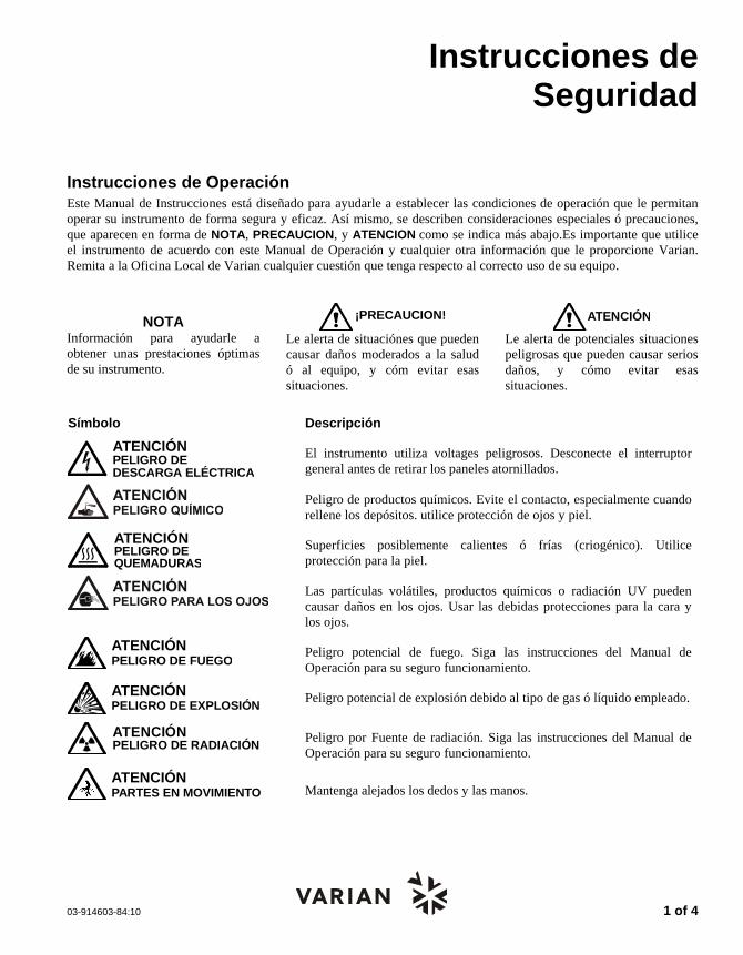
Instrucciones de Operación Este Manual de Instrucciones está diseñado para ayudarle a establecer las condiciones de operación que le permitan operar su instrumento de forma segura y eficaz. Así mismo, se describen consideraciones especiales ó precauciones, que aparecen en forma de NOTA, PRECAUCION, y ATENCION como se indica más abajo.Es importante que utilice el instrumento de acuerdo con este Manual de Operación y cualquier otra información que le proporcione Varian. Remita a la Oficina Local de Varian cualquier cuestión que tenga respecto al correcto uso de su equipo.
NOTA Información para ayudarle a obtener unas prestaciones óptimas de su instrumento.
¡PRECAUCION!
Le alerta de situaciónes que pueden causar daños moderados a la salud ó al equipo, y cóm evitar esas situaciones.
ATENCI NÓ
Le alerta de potenciales situaciones peligrosas que pueden causar serios daños, y cómo evitar esas situaciones.
Símbolo Descripción
ATENCIÓNPELIGRO DEDESCARGA ELÉCTRICA
El instrumento utiliza voltages peligrosos. Desconecte el interruptor general antes de retirar los paneles atornillados.
Peligro de productos químicos. Evite el contacto, especialmente cuando rellene los depósitos. utilice protección de ojos y piel.
ATENCIÓNPELIGRO DEQUEMADURAS
Superficies posiblemente calientes ó frías (criogénico). Utilice protección para la piel.
Las partículas volátiles, productos químicos o radiación UV pueden causar daños en los ojos. Usar las debidas protecciones para la cara y los ojos.
ATENCIÓNPELIGRO DE FUEGO
Peligro potencial de fuego. Siga las instrucciones del Manual de Operación para su seguro funcionamiento.
ATENCIÓNPELIGRO DE EXPLOSIÓN
Peligro potencial de explosión debido al tipo de gas ó líquido empleado.
ATENCIÓNPELIGRO DE RADIACIÓN
Peligro por Fuente de radiación. Siga las instrucciones del Manual de Operación para su seguro funcionamiento.
ATENCIÓNPARTES EN MOVIMIENTO Mantenga alejados los dedos y las manos.

2 of 4 03-914603-84:10
Precauciones Generales de Seguridad Siga estas indicaciones de seguridad para una correcta operación del equipo.
Realice verificaciones periódicas de fugas en todas las líneas de suministro y tuberías.
No permita que las líneas de gas se doblen ó pinchen. Manténgalas alejadas de zonas de paso y del calor ó frío excesivo.
Guarde los disolventes orgánicos en cabinas ventiladas, a prueba de fuego, y etiquetadas para que puedan ser fácilmente identificadas como material tóxico y/ó inflamable.
No acumule disolventes inservibles. Deseche todo el material inservible a través de un programa especial de desechos y no a través del sistema convencional.
NOTA: Este instrumento ha sido testado bajo las normas de la Directiva EMC según requerimientos de la Marca CE de la Unión Europea. Por lo tanto, este equipo puede ser sensible a niveles de radiaciones / interferencias ó frecuencias que no estén incluidas dentro de los límites testados.
ATENCI NÓ
Este instrumento está diseñado para análisis cromatográfico de muestras preparadas apropiadamente. Debe ser operado usando gases y/ó disolventes apropiados y con unos niveles máximos de presión, flujos y temperaturas, según se describe en este manual.
ATENCI NÓ
El Usuario tiene la obligación de informar al Servicio Técnico de Varian cuando el instrumento vaya a ser empleado para análisis de muestras peligrosas de origen biológico, radioactivo ó tóxico, antes de comenzar a realizar cualquier análisis.
Peligros Eléctricos Desconecte el instrumento de todos las conexiones eléctricas a la red antes de retirar los
paneles para evitar la posible exposición a peligrosos voltages. Cuando sea necesario emplear una clavija eléctrica no original, asegurese de colocar los
cables de acuerdo con el código de colores y polaridades descritos en el manual y los códigos de seguridad de la red eléctrica.
Sustituya los fusibles fundidos con fusibles del tipo y tamaño estipulados en el panel de fusibles ó en el manual.
Sustituya los cables deteriorados inmediatamente con cables del mismo tipo y graduación.
Asegureses de que los valores de las líneas de electricidad se ajustan a los valores para los que el Instrumento ha sido preparado.
Botellas de Gas Comprimido Guarde y maneje las botellas de gas con cuidado y de acuerdo con las normas de seguridad. Asegure las botellas a una estructura inmovil ó a la pared. Guarde y mueva las botellas en posición vertical. Retire los reguladores antes de
transportarlas. Guarde las botellas en un área ventilada, lejos de fuentes de calor, de luz solar directa y de
temperaturas extremadamente bajas. Identifique las botellas claramente para evitar cualquier duda sobre su contenido. Utilice sólamente reguladores y conexiones aprobadas. Utilice sólo tubos de conexión cromatográficamente límpios (Varian p/n 03-918326-00) y que
tengan una graduación de presión significativamente mayor que la mayor presión del regulador.

03-914603-84:10 3 of 4
GC Prácticas de Seguridad Sistema de Extracción No se necesita un sistema de extracción para los detectores GC instalados en un laboratorio bien ventilado, excepto cuando se analicen muestras químicas peligrosas. Si instala un sistema de extracción:
Utilice conductos a prueba de fuego.
Instale un ventilador al final del sistema.
Instale entradas de aire cuya vibración no afecte al trabajo del detector.
Compruebe periódicamente el correcto funcionamiento del sistema.
Asegurese de una correcta ventilación del laboratorio.
Detectores con fuentes radioctivas
Lea con cuidado y cumpla todas las NOTAS, PRECAUCION, y ATENCION del Manual del Detector Ni63 ECD.
Realice los test de contaminación radioactiva descritos en el Manual del Detector Ni63 ECD.
Cumpla con los plazos y procedimientos de test de fugas.
Peligro de Quemaduras Las zonas de calor ó frío (criogénicas) del Cromatógrafo de Gases pueden permanecer calientes ó frías durante bastante tiempo después de apagar el instrumento. Para evitar quemaduras asegureses de que todas las áreas que se calienten ó enfríen han vuelto a la temperatura ambiente, ó protejase adecuadamente las manos, antes de tocar las superficies potencialmente calientes ó frías.
LC Prácticas de Seguridad Peligro de Alta Presión Si se rompe una línea de presión, ó se abre una válvula de seguridad accidentalmente bajo presión, la bomba puede generar líquidos a alta presión potencialmente peligrosos, produciendo un chorro a alta velocidad de líquidos volátiles y/ó tóxicos.
Lleve protección facial cuando inyecte muestras ó realice mantenimiento de rutina.
Nunca abra una línea ó una válvula bajo presión. Apague la bomba antes y deje que la presión baje a cero.
Utilice depósitos irrompibles que sean capaces de operar a 50-60 psi.
Mantenga cerrada la junta del depósito cuando se haye bajo presión.
Lea y cumpla todas las NOTA, PRECAUCION, y ATENCION del manual.
Cromatografía Flash El operador debe familiarizarse con las propiedades físico-químicas de los componentes de la fase móvil.
Alejar los disolventes del contacto directo con los tubos de poliuretano ya que ciertos disolventes pueden causar reblandecimiento de los tubos o posibles fugas con riesgo de explosión.
Todos los componentes del sistema deben estar conectados a un enchufe común con toma de tierra común. Esta toma de tierra debe ser una toma de tierra verdadera en lugar de flotante.
Los disolventes no-polares pueden originar carga estática cuando son bombeados por el sistema. Todos los recipientes que contienen fase móvil (incluyendo los tubos y los recipientes de recogida) deben estar conectados a tierra para disipar la electricidad estática.
Utilizar medidores de carga estática y los debidos dispositivos de descarga (por Ej., ionizadores de aire) para salvaguardarse contra la creación de electricidad estática.
Radiación Ultravioleta Los detectores del Cromatógrafo de Líquidos que utilizan una fuente de luz ultravioleta disponen de protección para prevenir exposiciones radioactivas al personal.
Para una correcta protección:
Asegurese de que las cubiertas de protección de la lámpara de los detectores está correctamente situada durante su funcionamiento.
No mire directamente a las celdas del detector ó a la fuente de luz UV. Cuando inspeccione la fuente de luz ó la celda, utilice siempre una protección para los ojos como gafas de borosilicato ó poliestireno.

4 of 4 03-914603-84:10
Disponibilidad de Recambios Es Política de Varian disponer de Recambios para cualquier instrumento y la mayoría de los accesorios por un periodo de cinco (5) años después del último instrumento fabricado. Los recambios durante esos cinco años estarán disponibles, pero siempre bajo el sistema “Según disponibilidad”. Los Recambios están definidos como todas aquellas partes individuales mecánicas ó eléctricas que son susceptibles de fallo durante su normal proceso de operación. Por ejemplo, relés, lámparas, sondas de temperatura, elementos del detector, motores, etc. Las planchas de metal, partes de la estructura, placas de circuitos integrados, y otros módulos funcionales son normalmente susceptibles de reparación y por lo tanto sólo estarán disponibles bajos el sistema “Según disponibilidad” después del último instrumento fabricado.
Disponibilidad de Servicio Varian ofrece una gran variedad de sistemas de Servicio para mantener el soporte a sus usuarios tras el periodo de garantía. El Soporte de Servicio se ofrece a través de atractivos Contratos de Servicio ó bajo un sistema de facturación de mano de obra y materiales. El mantenimiento y el entrenamiento se realiza por ingenieros cualificados bajo Contrato ó petición.
Oficinas de Instrumentación Analítica Varian Para cualquier consulta sobre Instrumentación Analítica, Servicio Técnico ó Recambios y Accesorios, contacte con su oficina local: Argentina Buenos Aires Tel. +54.11.4.783.5306
Australia Mulgrave, Victoria Tel. +61.3.9566.1134
Austria Vösendorf bei Wien Tel. +43.1.699.9669
Benelux Bergen Op Zoom Tel. +31.164.282.800
Brazil and Latin America (S) São Paulo Tel. +55.11.820.0444
Canada Mississauga, Ontario Tel. 800.387.2216
China Beijing Tel. +86.106209.1727
Europe Middelburg, The Netherlands Tel. +31.118.671.000
France Les Ulis Cédex Tel. +33.1.6986.3838
Germany Darmstadt Tel. +49.6151.7030
India Mumbai Tel. +91.22.857.0787/88/89
Italy Torino Tel. +39.011.997.9111
Japan Tokyo Tel. +81.3.5232.1211
Korea Seoul Tel. +82.2.345.22452
Mexico and Latin America (N)Mexico City Tel. +52.5.523.9465
Russian Federation Moscow Tel. +7.095.937.4280
Spain Madrid Tel. +34.91.472.7612
Sweden Solna Tel. +46.8.445.1620
Switzerland Varian AG Tel. +41.848.803.800
Taiwan Taipei Hsien Tel. +886.2.698.9555
United Kingdom and Ireland Walton-on-Thames Tel. +44.1932.898000
Venezuela Valencia Tel. +58.41.257.608
United States Walnut Creek, California, USA Tel. +1.800.926.3000 (GC and GC/MS)
Tel. +1.800.367.4752 (LC)
www.varianinc.com

PrepStar SD-1 i
Table of Contents Introduction.............................................................................................. 1 Description...........................................................................................................................1
Installation................................................................................................ 3 Unpacking............................................................................................................................3 Location ...............................................................................................................................4 Quick Set Up........................................................................................................................4
Electrical Connections ..................................................................................................5 Plumbing Connections ..................................................................................................5
Electrical Setup..................................................................................................................10 Fuse/Line Voltage .......................................................................................................10 Power Connection.......................................................................................................10 External Contacts Panel .............................................................................................10 Serial Interface Connections for Remote Control by Dynamax HPLC Method Manager, Dynamax PC or Star Workstation...............................................................15
Plumbing the PrepStar SD-1 Solvent Delivery System.....................................................17 Low Pressure Solvent Inlet .........................................................................................18 High Pressure Outlet...................................................................................................18 Priming the PrepStar SD-1 .........................................................................................20
Plumbing the HPLC system...............................................................................................21 General .......................................................................................................................21 Isocratic HPLC Systems .............................................................................................22 Gradient HPLC Systems.............................................................................................23 AutoPrep HPLC System..............................................................................................25
Initial Operation..................................................................................................................26
Instrument Description ......................................................................... 31 Front View..........................................................................................................................31 Back View ..........................................................................................................................33 Keypad...............................................................................................................................34 SD-1 Displays ....................................................................................................................36
Cursors........................................................................................................................36 HOME Display.............................................................................................................37 Main Displays..............................................................................................................38 Special Displays..........................................................................................................40
Operation................................................................................................ 45 Safety Considerations .......................................................................................................45
Operator Safety...........................................................................................................45

ii
Instrument Considerations ..........................................................................................45 Initial Operation..................................................................................................................47
Power Up ....................................................................................................................47 Flush the HPLC System..............................................................................................48 Check for Leaks Against System Backpressure.........................................................48
Setting Flow and Maximum Pressure................................................................................49 Power Up ....................................................................................................................49 Setting Maximum Pressure.........................................................................................50
Changing the Liquid Heads ...............................................................................................51 Liquid Head Removal..................................................................................................52 Liquid Head Replacement...........................................................................................56
Remote Operation .............................................................................................................58
Maintenance and Troubleshooting ...................................................... 61 Maintenance ......................................................................................................................61 Service Logs ......................................................................................................................61 Seal Replacement .............................................................................................................62
Dismantling the Liquid Head .......................................................................................64 Removing Seals/O-ring...............................................................................................66 Replacing Seals/O-ring ...............................................................................................66
Piston Replacement ..........................................................................................................68 Removing the Old Piston Assembly............................................................................68 Installing the New Piston Assembly ............................................................................69
Check Valve Replacement ................................................................................................69 Cleaning the Check Valves.........................................................................................71 Removing the Check Valves.......................................................................................71 Installing the Check Valve Cartridge...........................................................................72 Replacing the Check Valve.........................................................................................74
Fuse Replacement ............................................................................................................75 Troubleshooting.................................................................................................................76
“Reading” the Pressure Display..................................................................................76 Troubleshooting Guide ......................................................................................................77 Error Messages .................................................................................................................81
Appendix ................................................................................................ 83 Specifications.....................................................................................................................83 Maximum Pressure vs. Flow .............................................................................................85 Accessories .......................................................................................................................85 Replacement Parts ............................................................................................................86 Scale-Up ............................................................................................................................88 System Requirements for High Performance Prep Chromatography ...............................88 Scale-Up HPLC System ....................................................................................................90 The Scale-Up Process.......................................................................................................91

PrepStar SD-1 1
Introduction Description
The PrepStar SD-1 is an innovative HPLC solvent delivery system engineered with preparative chromatographers in mind. A powerful drive unit and dual interchangeable pump heads provide pumping capacity to 3.2L per minute at pressures of up to 375 psi (25 bar) for superior throughput with large high-resolution microparticulate columns. For bench-scale prep, 200 mL per minute and 50 mL per minute heads provide flow at pressures up to 6000 psi (410 bar) and 10,000 (690 bar) psi, respectively. Corrosion-resistant titanium pump heads address the needs of biochemists for compatibility with salt-containing buffers and freedom from unwanted metal ions. Each pump head has a piston washing chamber to prevent deposition of abrasive salt residues behind the high-pressure seal, thereby greatly extending seal life.
Major new technology includes dual independent linear piston drives. Rather than operating both heads from cams attached to a single motor, as in conventional dual piston pumps, the SD-1 uses two independent stepper motors which connect to pistons via linear screw drives. The motors reciprocate, rather than running only in one direction. Independent drive frees the SD-1 from the operating constraints of mechanical cam profiles and makes it the first dual piston pump to produce entirely pulse-free flow under all operating conditions, without auxiliary hydromechanical pulse dampers. Totally pulse-free flow favors improved column performance and extended column life by saving expensive preparative columns from the constant pressure-pulse pounding typical of other large piston and diaphragm pumps.
In addition, the SD-1 meters flow at a constant rate independent of solvent compressibility and without the slight refill-associated flow deficits seen with conventional single-motor dual-piston models. In gradient operation, this produces more precise composition profiles without the time and volume delays introduced by large mixing chambers. Plus, flow rates extend

2 03-914794-00:3
well into the analytical HPLC range, permitting method development on smaller columns without interchanging heads.
Each SD-1 pump includes a standard serial interface for flow control. A built-in two-channel analog-to-digital converter allows the computer to collect data from HPLC detectors. Contact closure inputs and outputs are provided for system automation. Firmware includes GLP logging features. This manual emphasizes wherever possible Macintosh computer software usage, but similar functions are available using PC compatible software such as Star Workstation and Dynamax PC.

PrepStar SD-1 3
Installation Unpacking
WARNING
The PrepStar SD-1 weighs approximately 75 lbs (34 kg). Get help and carefully lift the pump from the shipping container.
Place the PrepStar SD-1 on a flat surface and inspect for damage.
Damage in transit is the responsibility of the carrier. If any damage is found, contact the carrier and immediately. Many carriers must receive a damage claim within 7 days of delivery, and will need to see the shipping container.
Inspect the shipping container for indications of damage. In North America damage occurring during transit is the responsibility of the carrier and should be reported immediately to the carrier and to:
Varian, Inc. 2700 Mitchell Drive Walnut Creek, California 94598-1675 Attention: Customer Service 1-800-FOR-HPLC
Outside North America, please contact the carrier and your local Varian office.
For contents of shipping container see the Standard Accessory Kit list in the shipping box.
Carefully unpack the PrepStar SD-1 Solvent Delivery System.
It is a good idea to save the shipping container and packing material. They provide excellent protection for the instrument in case of future transit or storage.

4 03-914794-00:3
Location
WARNING
The PrepStar SD-1 weighs approximately 75 lbs (34 kg). Get help and carefully lift the pump from the shipping container.
Place the PrepStar SD-1 on a flat, stable bench adjacent to the rest of the HPLC system. Two pumps may be stacked, however if you have three PrepStar SD-1 pumps, place the third pump on the bench next to the other two. Do not stack more than two high. Although the PrepStar SD-1 is very stable in operation, it is a good idea to avoid locations with extreme changes in temperature, such as in direct sunlight, near an open window, or beneath an air-conditioner vent. Place each pump with at least 4” (10 cm) clearance behind the pump to allow for the unrestricted flow of cooling air. If the equipment is used in a manner not specified, the protection provided by the equipment may be impaired.
Quick Set Up This section allows you to quickly set up and use the pump to check operation.
The procedure describes a very basic pumping system: one pump, front panel control, recirculating solvent, and no column attached. The pump should be unpacked and on the bench. Fuses are installed, ready for operation. Position each PrepStar SD-1 pump so that there is at least a 4” clearance behind the pump to allow for unrestricted cooling air flow.
The accessories package includes: a power cord, solvent inlet assembly, compression fitting, and ferrule.
You will also need up to 3L of HPLC-grade water, solvent reservoir, adhesive tape, 1/4", 5/16", and ½" open-ended wrenches, plus standard lab safety equipment including safety glasses, gloves, and lab coat.

INSTALLATION
PrepStar SD-1 5
SD-1 SOLVENT DELIVERY SYSTEM
HIGH PRESSURE TEEOUTLET CHECKVALVE FITTINGOUTLET CHECK
VALVE
LIQUID HEADNAMEPLATE
LIQUID HEAD
PRESSURE SENSORCABLE CONNECTOR
PRESSURESENSOR CABLE
INLET CHECKVALVE
INLET CHECKVALVE FITTING LOW PRESSURE
INLET TUBINGLOW PRESSURE
INLET TEE
LOW PRESSUREINLET
HIGH PRESSUREOUTLET
FLOW DIRECTION (ONE SIDE SHOWNFOR CLARITY.)
Figure 1 Front Panel: Liquid End Detail
Electrical Connections 1. For each PrepStar SD-1 set the power switch on the front
panel to OFF. (O=OFF, I=ON).
2. Connect the AC power cord to the power receptacle on the back panel. Plug the other end into a grounded power source.
Plumbing Connections 50 through 800 mL head sizes
Low Pressure Inlet
1. Remove the solvent inlet assembly from the accessories package and immerse the inlet filter into clean, HPLC-grade water.
6 03-914794-00:3
2. Remove the plug from the low pressure inlet tee and connect the inlet fitting to the inlet tee. Put the plug in a safe place, you will need it when you change liquid heads.
3. Thread the fitting into the inlet tee and fingertighten. With a 1/2" wrench, tighten the fitting no more than 1/4-turn past fingertight.
High Pressure Outlet 1. Refer to the following figure to find the outlet connections for
your SD-1 pump. The appropriate compression fitting for your SD-1 pump is in the accessories package.
2. Remove the plug from the outlet tee port. Store the plug in a safe place. Assemble the ferrule (and ferrule collar for PEEK tubing) and compression fitting onto the outlet tubing as shown. For PEEK ferrules, place the ferrule collar onto the shoulder of the ferrule, large opening toward the ferrule. (The collar will seat properly as you tighten the fitting.)
3. Holding the compression fitting, ferrule and collar in place on the tubing, push the end of the tubing as far as possible into the port on the outlet tee.
4. Carefully thread the compression fitting into the outlet port on the tee. Tighten the compression fitting fingertight. With a 5/16" wrench, tighten 1/4-turn past fingertight.
5. Immerse the other end of the outlet tubing into the solvent in the reservoir, and tape the outlet tubing to the neck of the solvent reservoir. It is important to tape the tubing firmly in place.

INSTALLATION
PrepStar SD-1 7
Figure 2 Outlet Connections
3.2L Heads
1. Inlet and outlet plumbing use flared tubing compatible with Fluoroware® Flaretek® fittings.
CAUTION
These fittings, with the exception of the check valves, should only require hand tightening. Use of tools such as wrenches or pliers to tighten them may damage the fitting or cause the tubing to fail under pressure
Compression Fitting R0-071056-02
Compression Fitting R0-071056-02
Compression Fitting R0-071056-02
SS tubing
SS Ferrule R0-071056-02
SS Tubing
SS Ferrule R0-071056-02
Peek Tubing
Compression Fitting R0-071056-02
SS Tubing
SS Ferrule R0-071056-02
Compression Fitting R0-071056-02
Peek Tubing Ferrule Collar (see detail)Peek Ferrule R0-000LT1-00
Ferrule Collar(see detail) Peek FerruleR0-000LT2-00
Compression Fitting R0-071056-04
Peek Tubing
Ferrule Collar (see detail) Peek Ferrule R0-000LT2-00
Heat forming flare
3.2L Fluoroware® FL4-1 Nut, 1/4" x .047 FEP Tubing
50 mL/min Stainless Steel
50 mL/min Titanium with Titanium tubing (over 2500 psi)
50 mL/min Titanium with PEEK tubing (up to 2500 psi)
200 mL/min Titanium with SS tubing (over 2500 psi)
200 mLmin Titanium with PEEK tubing (up to 2500 psi)
500/800 mL/min Titanium with PEEK tubing (up to 2500 psi)
Detail of PEEK ferrule and ferrule collar
Small opening at top

8 03-914794-00:3
2. Remove and save the white shipping plug from the inlet valve and attach the inlet and outlet tube assemblies. See the following figure for suggested inlet and outlet configurations. The inlet tube to the solvent reservoir should be kept short, less than a few feet, since a long tube may result in large inlet pressure oscillations. It is recommended that tubing and reservoirs be flushed with air or filtered solvent and that only filtered solvent be used in the system.
Figure 3 Connections for 3.2L Pump Heads
Priming the PrepStar SD-1
NOTE: All heads are self-priming.
1. Tighten the outlet tee fitting 1/4-turn past fingertight.
Wrench tighten these only.
Inlet assembly 1/2" OD FEP tubing
Outlet assembly 1/4" OD FEP tubing

INSTALLATION
PrepStar SD-1 9
2. Switch on the pump power by pressing the ON/OFF switch. After a few moments the FLOW screen is displayed:
0.00 mL/m 0 psi
TIME0.00
FLOW-0.00-
If the FLOW field is not flashing, press the right arrow key to get the cursor to the FLOW field.
3. Press the following keys to set a high flow rate for self-priming
40 mL/min for the 50 mL/min liquid head
150 mL/min for the 200 mL/min liquid head
400 mL/min for the 800 mL/min liquid head
600 mL/min for the 800 mL/min liquid head
2000 mL/min for the 3.2L/min liquid head
4. Start the pump by pressing ENTER.
5. The pump will start to run and solvent will be drawn into the solvent inlet line. After the inlet line is full, let the pump continue to run for a few moments until the pressure display is steady.
6. Press STOP to stop the pump.
7. The PrepStar SD-1 pump is now primed. Switch off the SD-1 by pressing the ON/OFF switch.
4
1 5
0 4
0 6
2 0
0
0
0
0
0 0
ENTER
ENTER
ENTER
ENTER
ENTER

10 03-914794-00:3
Electrical Setup
Fuse/Line Voltage PrepStar SD-1 pumps are shipped with fuses installed, ready for operation at the line voltage at the shipping destination. The fuses are as follows:
USA: 3AG 10A 250V Slo-Blo Europe: 5 x 20 mm, 5A 250V, fast-acting, high breaking capacity
Two spare fuses are supplied in the accessories kit. Fuse installation is described in Maintenance and Troubleshooting.
Power Connection For each PrepStar SD-1, check that the power switch on the front panel is OFF. (ON= =I, OFF= =O).
Connect the AC power cord to the power receptacle on the back panel of the SD-1 pump. Plug the other end into a grounded power socket or terminal strip, preferably in the same circuit as other components in the HPLC system.
Grounding is necessary to ensure operator safety and proper operation of the PrepStar SD-1.
External Contacts Panel The external contacts panel is on the back panel. The external contacts panel can be removed for convenience when attaching the wires.
Remove the panel by loosening the three captive screws holding it in place and pulling the handle away from the pump.
After attaching the wires, replace the panel by carefully aligning the main connector and firmly pushing it in place. Then tighten the captive screws fingertight.

INSTALLATION
PrepStar SD-1 11
Pin connections for each terminal block on the panel are described in the following pages.
TB 3RELAY OUTPUT
HANDLECAPTIVE SCREW CAPTIVE SCREW
CAPTIVE SCREW
TB 2DIGITAL INPUT
TB 1ANALOG
1
2
3
4
5
6
STOP
HOLD
TRANSFER
INJECT
MARK
CHASSISGND
D GND
D GND
D GND
D GND
D GND
CHASSISGND
CHASSISGND
INTGR 2HI
AUX + 5V
INTGR 1HI
INTGR 1LO
INTGR 1GND
INTGR 2LO
INTGR 2GND
CHASSISGND
CHASSISGND
CHASSISGND
ANALOGOUT
ANALOGGND
METH
OD
12
34
56
78
910
1112
12
34
56
78
910
1112
12
34
56
78
910
1112
Figure 4 PrepStar SD-1 External Contacts Panel (panel turned 90° for clarity)
TB-1 Analog
INTGR 1 HI Connect the “high” signal line from the Channel A detector. Range -0.5 to 2.5V.
INTGR 1 LO Connect the “low” signal line from the Channel A detector.
INTGR 1 GND Connect the “ground” line (if present) from the Channel A detector.
INTGR 2 HI Connect the “high” signal line from the Channel B detector. Range -0.5 to 2.5V.
INTGR 2 LO Connect the “low” signal line from the Channel B detector.
INTGR 2 GND Connect the “ground” line (if present) from the Channel B detector.

12 03-914794-00:3
CHASSIS GND Connected internally to case ground.
CHASSIS GND Connected internally to case ground.
CHASSIS GND Connected internally to case ground.
ANALOG OUT The “analog out” connections are bi-functional.
ANALOG GND 1 For wavelength control from Dynamax Method Manager (Mac)/Star Workstation (PC) using a ProStar 320, connect this output to the “External Wavelength” input of the detector.
Open DA –> System menu –> Set Up. In the Set-Up window open the “Detector” pop-up menu, select ProStar 320. Open the Manual Control window.
Ensure that power is on to the SD-1 and the detector.
Make several wavelength changes in the Manual Control window:
On a ProStar 320, you should see the absorbance display changing as the wavelength is changed.
For Wavelength Control, 1 volt = 100 nm.
Alternatively, Analog Out can be used to output the pressure signal in mV, when the contacts are not used for wavelength control and when the “Analog Out - Y N” menu item in the PrepStar SD-1 Pressure menu is selected to ON.
For Analog Out, 1 volt = 1000 psi, (68 bar).
NOTE: The pressure signal output is CANCELLED when Dynamax Method Manager (Mac) uses these outputs for wavelength control.
CHASSIS GND Connected internally to case ground.

INSTALLATION
PrepStar SD-1 13
TB-2 Digital Input
CAUTION
Voltages in the range -0.5 VDC to +5.5 VDC may be applied. Damage to the PrepStar SD-1 may occur with other voltages.
STOP
D GND
Contact closure sends a “Stop Pump” signal to the PrepStar SD-1 which will send it to a connected data system such as the Dynamax Method Manager. If there is no “Shutdown” method specified in the Dynamax Method Manager loop-link window, this input stops the pump immediately and informs Dynamax Method Manager or Star Workstation that the pump has stopped. If there is a Shutdown method specified, Dynamax Method Manager or a shutdown is part of the Star Workstation method, control will branch to that method, either immediately, or after the current method pass, depending on the preference in the loop-link window.
HOLD Contact closure sends a “Hold Flow Rate” signal to Dynamax Method Manager. Contact closure duplicates the HOLD button on the front panel.
TRANSFER Contact closure sends a “Transfer Method” signal to Dynamax Method Manager. If there is no “Link” method specified in Dynamax Method Manager loop-link window, the method will stop looping after the current method pass. If there is a Link method specified, the method will stop looping AND transfer to the Link method at the end of the current method pass.
INJECT D GND
Connect these inputs to the position sensing switch of the injector or to the “injection complete” output from the automatic sample injector. The contact should close when the valve is in the “Inject” position, or when the autosampler completes injection.
Contact closure cancels “Inject Wait” programmed in pump and CIM program of the Star Workstation Method or Method Manager ME (Mac).

14 03-914794-00:3
MARK D GND
Inputs can accept all contact closures relays, open collector transistors, and open collector integrated circuits. When there is no event, the input must be greater than 4.75V; with a contact closure, the input must be equal to or less than 1.2V with a duration of 0.1 seconds or longer. When Event Marking has been set up in Dynamax DA (Mac), an event mark will be shown on the display and in the printed report as a vertical dotted line at the leading edge of the contact closure. To set up Dynamax DA or Star Workstation to display Event Marks, refer to Event Marking in the Dynamax Method Manager or Star Workstation manual.
AUX + 5V Provides 5V logic voltage with a 47-ohm resistor in series. Low current loads (less than 20 milliamperes) such as sensitive relays, LEDs, and simple logic circuits can be run off this output.
To maintain output greater than 4.75V, the load must be less than 5mA.
CHASSIS GND
Connected internally to case ground.
TB-3 Relay Output
The “relay out” connectors are for switching power to user-defined external devices to be controlled by Dynamax HPLC Method Manager, or the Star Workstation. Each pair of output connectors is connected to a relay inside the PrepStar SD-1. Refer to Figure 4.

INSTALLATION
PrepStar SD-1 15
CAUTION
Maximum voltage for relay outputs is 24 VDC; maximum current is 1A. Do not exceed these limits. Attempting to switch voltages or currents higher than the specified limits will reduce contact life and may damage the PrepStar SD-1. To use these outputs to operate any inductive-load devices please first call LC Technical Services at 1-800 FOR-HPLC. (In Europe, please contact your Varian representative.) If any device you are switching requires higher voltage or current than these maximum ratings, use an auxiliary power relay to isolate the device from the PrepStar SD-1. Attempting to switch voltages or currents higher than the specified limits will reduce contact life and may damage the PrepStar SD-1.
Serial Interface Connections for Remote Control by Dynamax HPLC Method Manager, Dynamax PC or Star Workstation
To connect the PrepStar SD-1 for remote control by Dynamax Method Manager or Star Workstation.
1. Refer to Figure 5, Figure 6, and Figure 3A. Connect the serial interface cable from Dynamax Method Manager, Dynamax PC, or Star Workstation.
2. Plug the 8-pin round connector on the serial interface cable into the modem port on the Macintosh (marked with a telephone).
3. The four 9-pin female connectors on the serial interface cable are all equivalent.
Connect one of the connectors to the serial interface port on each SD-1 pump being used. (Extra connectors may be left unconnected.)
4. If connecting - plug the AC connector on the serial interface cable into the AC power supply.
5. See page 58 for Remote Operation by Dynamax HPLC Method Manager.
6. For PC connections refer to Figure 6.

16 03-914794-00:3
SD-1 Pump B
Serial Interface CableAC Connector
SD-1 Pump A
Figure 5 Connections for Remote Operation - Macintosh
*For Remote Operation not using Dynamax Method Manager, Star Workstation, or Dynamax PC, see Appendix.
Computer
Macintosh
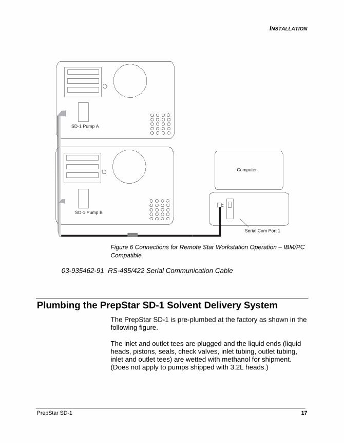
INSTALLATION
PrepStar SD-1 17
SD-1 Pump B
Computer
Serial Com Port 1
SD-1 Pump A
Figure 6 Connections for Remote Star Workstation Operation – IBM/PC Compatible
03-935462-91 RS-485/422 Serial Communication Cable
Plumbing the PrepStar SD-1 Solvent Delivery System The PrepStar SD-1 is pre-plumbed at the factory as shown in the following figure.
The inlet and outlet tees are plugged and the liquid ends (liquid heads, pistons, seals, check valves, inlet tubing, outlet tubing, inlet and outlet tees) are wetted with methanol for shipment. (Does not apply to pumps shipped with 3.2L heads.)
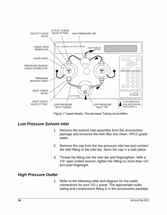
18 03-914794-00:3
Figure 7 Liquid Heads, Pre-plumbed Tubing Assemblies
Low Pressure Solvent Inlet 1. Remove the solvent inlet assembly from the accessories
package and immerse the inlet filter into clean, HPLC-grade water.
2. Remove the cap from the low pressure inlet tee and connect the inlet fitting to the inlet tee. Store the cap in a safe place.
3. Thread the fitting into the inlet tee and fingertighten. With a 1/2" open ended wrench, tighten the fitting no more than 1/4-turn past fingertight.
High Pressure Outlet 1. Refer to the following table and diagram for the outlet
connections for your SD-1 pump. The appropriate outlet tubing and compression fitting is in the accessories package.

INSTALLATION
PrepStar SD-1 19
Size/Type of Liquid Head Size/Type of Tubing 50 mL/min Stainless 1/16 inch OD Stainless 50 mL/min Titanium (over 2500 psi) 1/16 inch OD Stainless or Titanium 50 mL/min Titanium (up to 2500 psi) 1/16 inch OD PEEK 200 mL/min Titanium (over 2500 psi) 1/16 inch OD Stainless or Titanium 200 mL/min Titanium (up to 2500 psi) 1/16 inch OD PEEK 500 mL/min Titanium 1/8 inch OD PEEK 800 mL/min Titanium 1/8 inch OD PEEK 3200 mL/min Titanium 1/4 inch OD FEP
The types of compression fitting assemblies are shown in Figure 2 and Figure 3 (2500 psi = 171 bar).
2. Remove the plug from the outlet tee port. Store the plug in a safe place. Assemble the ferrule (and ferrule collar for PEEK tubing) and compression fitting onto the outlet tubing as shown in Figure 2. For PEEK ferrules, place the ferrule collar onto the shoulder of the ferrule, large opening toward the ferrule. (The collar will seat properly as you tighten the fitting.)
3. Holding the compression fitting, ferrule and collar in place on the tubing, push the end of the tubing as far as possible into the port on the outlet tee.
4. Carefully thread the compression fitting into the outlet port on the tee. Tighten the compression fitting fingertight. With a 5/16" wrench, tighten the fitting 1/4-turn past fingertight.
5. Immerse the other end of the outlet tubing into the solvent in the reservoir, and firmly tape the outlet tubing to the neck of the solvent reservoir.
(As an alternative you can finish connecting the PrepStar SD-1 through the drain valve to the rest of the HPLC system, see page 21, and prime the PrepStar SD-1 with the drain valve open to waste.)

20 03-914794-00:3
Priming the PrepStar SD-1
NOTE: All heads are self-priming.
1. Make sure that the outlet tee fitting is tightened 1/4-turn past fingertight.
2. Switch on the pump power by pressing the ON/OFF switch. After a few minutes the FLOW screen is displayed:
0 mL/M 0 psiTIME FLOW10.00 -0.50-
3. Press the following keys to set a high flow rate for self-priming:
40 mL/min for the 50 mL/min liquid head
150 mL/min for the 200 mL/min liquid head
400 mL/min for the 500 mL/min liquid head
600 mL/min for the 800 mL/min liquid head
2000 mL/min for the 3.2 L/min liquid head
4
1
4
ENTER
ENTER
ENTER
ENTER
ENTER
0
5 0
0 0
0 0 6
0 0 0 2

INSTALLATION
PrepStar SD-1 21
4. Start the run by pressing RUN.
The pump will start to run and solvent will be drawn into the solvent inlet line. After the inlet line is full, let the pump continue to run for a few moments until no more bubbles appear in the solvent reservoir.
5. Press STOP to stop the pump.
6. The PrepStar SD-1 pump is now primed. Switch off the SD-1 by pressing the ON/OFF switch.
Plumbing the HPLC system
General Connect the rest of the HPLC system components. Diagrams and brief descriptions follow for various types of HPLC system. For two-pump systems, SD-1 pumps can be stacked one on the other, and the mast used to hold the mixer, drain valve, inject valve, and column hanger. For three pump systems, stack two of the pumps and place the third on the bench. Do not stack more than two high. When stacking pumps, you can place a rubber mat between the pumps to reduce vibration and creep, especially at high flow rates.
When attaching new pieces of tubing to your HPLC system, leave the column inlet fitting disconnected until you have flushed the tubing ahead of the column, as described in Initial Operation on page 47. This will prevent impurities or particulates from the new tubing (such as dust, cutting oils, metallic particles, etc.) from clogging the column inlet frit or damaging the column.
New systems supplied from the factory have been set up and operated, so the tubing has already been flushed when you receive your system. In this case it is not necessary to disconnect the fitting to flush the system; opening the system drain valve and diverting the flow to waste is sufficient.

22 03-914794-00:3
Isocratic HPLC Systems
PrepStar SD-1
Injector Valve
DetectorFromSolventReservoir
Drain Valve
Column
Figure 8 Isocratic HPLC System Block Diagram
This is the simplest kind of HPLC system. The high pressure outlet from the PrepStar SD-1 connects to the system drain valve, to the injector valve, the column, then the detector flow cell. The outlet from the detector can be directed to waste or collected.

INSTALLATION
PrepStar SD-1 23
Gradient HPLC Systems
FromSolventReservoir A
FromSolventReservoir B
PrepStar SD-1Pump-A
High PressureMixer
Injector Valve
Drain Valve
PrepStar SD-1 Pump-B Detector
Colum
n
Figure 9 Binary Gradient HPLC System Block Diagram
Figure 9 shows two PrepStar SD-1 pumps, both under front panel control, used to pump two solvents in a gradient.

24 03-914794-00:3
FromSolventReservoir A
FromSolventReservoir B
PrepStar SD-1Pump-A
High PressureMixer
Injector Valve
Drain Valve
PrepStar SD-1 Pump-B Detector
Colum
n
Figure 10 Binary Gradient HPLC System with Computer Controller Block Diagram
Figure 10 shows a binary gradient HPLC system controlled by Dynamax HPLC Method Manager, Dynamax PC, or Star Workstation running on a Mac or PC computer. The software controls the flow rates for both PrepStar SD-1 pumps. Electrical connections between the pumps and the computer are shown earlier in this section in Figure 5 and Figure 6. Refer to the manual for Dynamax HPLC Method Manager, Dynamax PC, or Star Workstation, for information on programming the method.
Plumbing is the same for both these systems. The high pressure outlets from both PrepStar SD-1 pumps are connected to a high pressure mixer, to ensure that both solvents are mixed thoroughly. The system drain valve is plumbed after the mixer. The injector valve is plumbed after the drain valve, then the column, then the detector flow cell. The outlet from the detector can be directed to waste or collected.

INSTALLATION
PrepStar SD-1 25
AutoPrep HPLC System
From SolventReservoir B
Dynamax HPLCMacintosh withMethod Manager,or Star WS
PrepStar SD-1Pump-A
PrepStar SD-1 Pump-B
FromSolventReservoir A
High PressureMixer
Drain Valve
Column
Detector
To FractionCollector
PrepStar SD-1 PumpInject Pump
Sample InletTo Inject Pump
Tee
Figure 11 AutoPrep HPLC System with Computer Controller Block Diagram
This is a special binary gradient HPLC system which uses a third pump for sample injection, instead of an injection valve. All pumps are controlled by Dynamax HPLC Method Manager, Dynamax PC, or Star Workstation running on a Macintosh or PC computer.
The high pressure outlets from both PrepStar SD-1 solvent pumps are connected to a high pressure mixer. The system drain valve is plumbed after the mixer. The sample inject pump is plumbed into the system with a tee. The column is plumbed after the tee, then the detector. The outlet from the detector flow cell would normally be connected to a fraction collector.
Refer to the Dynamax HPLC Method Manager, Dynamax PC, or Star Workstation manual for instruction on AutoPrep operation.

26 03-914794-00:3
Initial Operation
NOTE: The values used in this procedure assume that a 200 mL/min head is in use.
For 50 mL/min heads divide the flow values by 4. For 500 mL/min heads multiply the flow values by 2.5. For 800 mL/min heads multiply the flow values by 4. For 3.2 L/min heads multiply the flow values by 16.
Switch on the PrepStar SD-1
1. Press the ON/OFF switch. The pump displays the following screen and begins a diagnostic check. “OK” appears when the check is complete.
SOLVENT DELIVERY SYSTEMSELF TEST RAM... OK
2. The diagnostic screen disappears and the screen below is displayed. This screen is used to set flow rate: it can be accessed at any time by pressing the FLOW button.
0.00 mL/m 0 psiTIME FLOW0.00 -0.00-
3. The values for TIME and FLOW in your display may be different from the example. Note the two dashes on either side of the FLOW value; these dashes (the cursor) indicate that the FLOW field can be edited.

INSTALLATION
PrepStar SD-1 27
5 4 2 • ENTER
Practice editing the FLOW field
4. Press
To set FLOW to 40 mL/min
To set FLOW to 25.40 mL/min
To set FLOW to 49.99 mL/min
5. Press move the cursor to the TIME (ramp time field).
Practice editing the TIME field:
6. Press
To set TIME TO 1 minute
To set TIME to 15 minutes
To set TIME to 5 minutes and 15 seconds,(5.25 minutes)
To set TIME to 2 minutes and 30 seconds,(2.5 minutes)
1
1
4
5
0 4
9 •
•
•
ENTER
9
2
ENTER
ENTER
ENTER9
5 5
ENTER
2 5
ENTER

28 03-914794-00:3
Start Pumping
7. To set the ramp time to 30 seconds, press
8. Press to move the cursor to the FLOW field.
9. To set the flow rate to 25 mL/min, press
10. Press RUN to start the pump. You will hear the pump begin its 30-second ramp, and on the top line of the display you can see flow and pressure values increasing. The elapsed ramp time will also be shown.
Change flow rate. HOLD and STOP keys
1. To set a new FLOW value of 45 mL/min, press
2. Press to move the cursor to the TIME field.
3. To set a new ramp time to 1 minute, press
4. Press RUN to start the ramp. You will hear the pump begin the new one minute ramp. On the top line of the display you can see flow and pressure values increasing. The elapsed ramp time will also be shown.
5 4
1
ENTER
5 • ENTER
5 2 ENTER
ENTER

INSTALLATION
PrepStar SD-1 29
5. After 15 to 20 seconds, press HOLD. The pump continues pumping at the flow reached when the HOLD key was pressed. The “frozen” elapsed ramp time, flow, and pressure values are displayed. “Hold” is shown.
6. Press RUN again to restart the pump.
7. After another 15 - 20 seconds, press STOP. The pump stops immediately. Pressing STOP always stops the pump and overrides any other key press or remote input. Flow will be zero.
8. The pump will start a new 1-minute ramp from current flow (0.00 mL/min) to the set flow (45 mL/min).
9. Experiment with setting various flow rates and ramp times.
Maximum Flow Test:
CAUTION
Before proceeding, make sure that the outlet tee connection is tightened 1/4-turn past fingertight and the other end of the outlet tubing is firmly taped into the solvent reservoir.
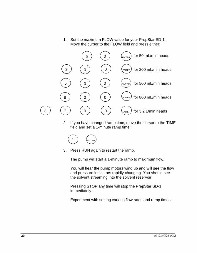
30 03-914794-00:3
1. Set the maximum FLOW value for your PrepStar SD-1. Move the cursor to the FLOW field and press either:
for 50 mL/min heads
for 200 mL/min heads
for 500 mL/min heads
for 800 mL/min heads
for 3.2 L/min heads
2. If you have changed ramp time, move the cursor to the TIME field and set a 1-minute ramp time:
3. Press RUN again to restart the ramp. The pump will start a 1-minute ramp to maximum flow. You will hear the pump motors wind up and will see the flow and pressure indicators rapidly changing. You should see the solvent streaming into the solvent reservoir. Pressing STOP any time will stop the PrepStar SD-1 immediately. Experiment with setting various flow rates and ramp times.
0
0 0
0 0
0 0
5
2
5
8
ENTER
ENTER
ENTER
ENTER
2 0 0 3 ENTER
1 ENTER

PrepStar SD-1 31
Instrument Description Front View
Figure 12 Front View
Low Pressure Inlet Tee Power Switch Inlet Check Valve
Pressure Sensor Cable
Outlet Check Valve
Liquid Crystal Display Liquid Head
High PressureTee
Keypad

32 03-914794-00:3
SD-1 SOLVENT DELIVERY SYSTEM
HIGH PRESSURE TEEOUTLET CHECKVALVE FITTINGOUTLET CHECK
VALVE
LIQUID HEADNAMEPLATE
LIQUID HEAD
PRESSURE SENSORCABLE CONNECTOR
PRESSURESENSOR CABLE
INLET CHECKVALVE
INLET CHECKVALVE FITTING LOW PRESSURE
INLET TUBINGLOW PRESSURE
INLET TEE
LOW PRESSUREINLET
HIGH PRESSUREOUTLET
FLOW DIRECTION (ONE SIDE SHOWNFOR CLARITY.)
Figure 13 Front Panel: Liquid End Detail

INSTRUMENT DESCRIPTION
PrepStar SD-1 33
Back View
Figure 14 Back Panel
Component Function External Contacts Panel
Contains three terminal blocks: TB-1 - ANALOG TB-2 - DIGITAL INPUT TB-3 - RELAY OUTPUT Terminal blocks and connections are described in Installation.
Over-Temperature Reset Switch
Safety feature cuts power to the SD-1 in case of overheating. The reset switch pops out. Restore power to the pump by pressing the reset switch back in place.
Serial Connector Miniature D-connector used only for remote pump control by Dynamax HPLC Method Manager, and Star Workstation Control/Data Acquisition software, or compatible PC software.
8-pin Mini-DIN Connector
8-pin miniature connector.
Fuse Holder Holds two fuses. Fuse replacement is described in Maintenance and Troubleshooting.
Power Receptacle Accepts standard grounded AC power cord. Fan Cooling fan draws cooling air into back of pump, blows warm air out of
bottom of pump. Do not obstruct fan: allow 4 inches of clearance.

34 03-914794-00:3
Keypad
Figure 15 Keypad
This key opens the FLOW window where the flow rate and ramp time are set. Maximum flow rate depends on the head size in use; maximum ramp time is 9999.99 minutes.
Opens the PRESSURE window where several pressure conditions can be set: Maximum pressure, pump action when maximum pressure is reached, minimum pressure, pressure units and analog pressure signal on/off.
Opens the Set Up and Service Log menus. The Set Up menu is used to start the head change sequence, set the Pump ID, the CIM ID, and to set the internal clock. The Service log is used to log piston seal changes, check valve changes/service intervals, and show the pump drive status.
FLOW
PRESS
∼

INSTRUMENT DESCRIPTION
PrepStar SD-1 35
UP/DOWN ARROWS: These keys are used to scroll up or down through preset values or toggle between choices. The Down Arrow key is also used to open menus.
LEFT/RIGHT ARROWS: These keys are used to move right and left in the display to access adjacent menus or values.
Pressing Run starts the ramp to the flow rate set in the FLOW window. The ramp time is set in the FLOW window.
Pressing this key holds the ramp at its current position. The time into ramp is displayed, with the flow rate and current pressure. This key is canceled by pressing RUN.
This key stops flow immediately.
NUMERIC KEYS: Used to set numeric values: flow rate, minimum and maximum pressure, ramp time, pump ID, CIM ID, date and time.
Used to cancel a user-entered value or choice, leaving the previously entered setting intact. Also used when changing heads.
Used to accept a new value or choice. Also used when changing heads.
ON/OFF SWITCH: Push-push switch turns power to the pump on or off. Connected directly to the power module on the back panel.
RUN
HOLD
STOP
9 0
CLEAR
ENTER
•

36 03-914794-00:3
SD-1 Displays
Cursors In the PrepStar SD-1 displays, editable parameters are indicated by one of four types of cursor. All types of cursors in the PrepStar SD-1 flash on both sides of the parameter to be edited.
Each type of cursor has a specific function, as described below:
0 0
NUMERIC ENTRY CURSOR: Used for numeric entry only.
Values entered or edited while the cursor is flashing are temporary until accepted by pressing the ENTER key, the RIGHT ARROW key, or the LEFT ARROW key. If the edited value is not accepted by pressing one of the above keys, or canceled by pressing the CLEAR key, the parameter reverts to its previous value after 60 seconds.
SCROLL CURSOR: Used when there is a preset list of choices.
Pressing the UP ARROW or the DOWN ARROW with this type of cursor is displayed scrolls up or down through the preset choices.
DUAL-MODE CURSOR: Preset list of choices and numeric entry.
Used when the value can be set either by numeric entry or by scrolling through a preset list of choices, as described above.
MENU CURSOR: Used when the selection is a menu.
Pressing the DOWN ARROW or the ENTER key with this type of cursor displays the next level of the menu.

INSTRUMENT DESCRIPTION
PrepStar SD-1 37
HOME Display The FLOW display (which is also the HOME display). This display shows when the PrepStar SD-1 starts up and can be accessed at any time by pressing the FLOW button. The top line of the display always shows current flow rate and pressures.
100.00 mL/m 450 psiRAMP
FLOW-250.00-
TIME
1.45
2.00
Figure 16 PrepStar SD-1 Flow Display
1 This area of the display shows the current state of operation (if any). Time is shown when ramping.
STOP The pump is stopped because:
• the STOP button has been pressed, or
• a STOP signal has been sent from Dynamax DA, or
• a PRESSURE LIMIT – STOP action has been received, or
• zero flow rate has been programmed.
RAMP The RUN button has been pressed and the pump is ramping to a new value. The elapsed ramp time is also shown in this area.
3 2 1
5 4
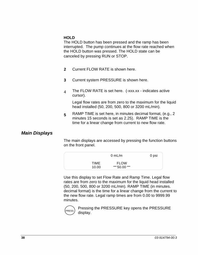
38 03-914794-00:3
HOLD The HOLD button has been pressed and the ramp has been interrupted. The pump continues at the flow rate reached when the HOLD button was pressed. The HOLD state can be canceled by pressing RUN or STOP.
2 Current FLOW RATE is shown here.
3 Current system PRESSURE is shown here.
4 The FLOW RATE is set here. (-xxx.xx - indicates active cursor).
Legal flow rates are from zero to the maximum for the liquid head installed (50, 200, 500, 800 or 3200 mL/min).
5 RAMP TIME is set here, in minutes decimal format, (e.g., 2 minutes 15 seconds is set as 2.25). RAMP TIME is the time for a linear change from current to new flow rate.
Main Displays The main displays are accessed by pressing the function buttons on the front panel.
0 mL/m 0 psi
TIME10.00
FLOW50.00
Use this display to set Flow Rate and Ramp Time. Legal flow rates are from zero to the maximum for the liquid head installed (50, 200, 500, 800 or 3200 mL/min). RAMP TIME (in minutes. decimal format) is the time for a linear change from the current to the new flow rate. Legal ramp times are from 0.00 to 9999.99 minutes.
Pressing the PRESSURE key opens the PRESSURE display.
PRESS

INSTRUMENT DESCRIPTION
PrepStar SD-1 39
MAX P3000
MAX P100
ACTIONlimitstop
UNITSpsibarmPa
PRESSURE DISPLAY 1
50.00 mL/m 1500 psi
RIGHT ARROW
EXTENDS TO RIGHT
To reach the rest of this display, press the right arrow key (indicated by the small arrow in the lower right corner). To reach the first part of the display again, press the left arrow key.
ANALOG PRESSURE MODULEOFFON
UNITSpsibarmPa
PRESSURE DISPLAY 2
50.00 mL/m 1500 psi
This display sets
MAX P: Maximum pressure ACTION: When Maximum Pressure is reached LIMIT flow to maintain the maximum pressure, or STOP the pump. MIN P: Minimum pressure. Pressure below which the pump will STOP - must go for about 10 seconds then stay below for 1/2 second to stop.
UNITS: Pressure units psi, bar or MPa ANALOG PRESSURE MONITOR: ON or OFF. Sends an analog signal [1000 psi/volt] to an external pressure monitor or chart recorder, if Dynamax Method Manager is not controlling detector wavelength through the ANALOG OUT contacts on the SD-1.
When controlling detector wavelength, DMM overrides this control and the SD-1 has to be switched OFF and ON to release the override.
Refer to page 11 for TB-1 Analog description.
Right arrow indicates that menu extends to right

40 03-914794-00:3
Special Displays
Pressing the SPECIAL key opens the SPECIAL display.
50.00 mL/m 1500 psi
SET UP
DISPLAY
SERVICELOG
The SET UP Menu performs the setup functions shown below.
SET UP DISPLAY
50.00 mL/m 1500 psi
HEADSCHANGE ID
DEVICE#PUMP CIM
SET CLOCKMM/DD/YY HH:MM:SS
NO NO 11 15 94 12 06 33
Use this display to
HEADS / CHANGE: Start the software-driven procedure to change liquid heads.
HEADS / ID: Display the size of liquid head installed and pressure maximum.
DEVICE# / PUMP Set the ID number for the pump. (When under the control of Dynamax HPLC Method Manager, or Star Workstation, each device in the HPLC system must have a unique ID number.)
DEVICE ID# / CIM Set the ID number for the built-in Control Interface.
SET CLOCK / MM/DD/YY Set month/day/year with numeric keys
SET CLOCK / HH:MM:SS Set hour/minute/second with numeric keys
SETUP

INSTRUMENT DESCRIPTION
PrepStar SD-1 41
The SPECIAL display is also used to access the SERVICE LOG menus
50.00 mL/m 1500 psi
SET UP SERVICELOG
DISPLAY
50.00 mL/m 1500 psi
PISTON PUMPSEALS DRIVE
SERVICE LOG DISPLAY
CHECKVALVES
The Service Log menu opens three log displays
1. PISTON SEAL LOG
50.00 mL/m 1500 psi
PISTON SEAL LOG DISPLAY
SEAL LOG DATE LIMITUSE CHANGED1 2/4/92 04 NO
This log shows
SEAL LOG Sequential number of last seal change. Previous log entries can be scrolled by pressing the UP ARROW.
DATE Date of last seal change.
USE Use units since last seal change. Use units are proportional to number of strokes and pump pressure.
LIMIT Number of units before another seal change. Set by user, depending on anticipated amount of use.

42 03-914794-00:3
CHANGED Scroll to YES when seal change is performed.
2. CHECK VALVE LOG
CHECK VALVE LOG DISPLAY
50.00 mL/m 1500 psi
CV LOG DATE LIMITUSE SERVICED?1 3/12/94 01 YES
This log shows
CV LOG Sequential number of last check valve service. Previous log entries can be scrolled by pressing the UP ARROW.
DATE Date of last check valve service.
USE Use units since last check valve service. Use units are proportional to number of strokes.
LIMIT Number of units before another service. Set by user, depending on anticipated amount of use.
SERVICED? Scroll to YES when check valve is serviced.
3. PUMP DRIVE LOG
PUMP DRIVE LOG DISPLAY
W-FACTOR1.47
K-CYCLES19
HOURS25
DRIVE:
50.00 mL/m 1500 psi

INSTRUMENT DESCRIPTION
PrepStar SD-1 43
This log shows
W-FACTOR Wear factor proportional to pressure.
K/CYCLES Number of piston strokes/1000.
HOURS Cumulative hours pump has been operating.

44 03-914794-00:3

PrepStar SD-1 45
Operation Safety Considerations
Operator Safety When handling potentially hazardous solvents and samples, it is important to follow standard laboratory safety procedures. Common chemicals used in the laboratory can be flammable, corrosive, toxic, reactive, or a combination of these. You should consult the MSDS (Material Safety Data Sheets, available from the manufacturer) for all chemicals used in your laboratory.
Listing all safety considerations is beyond the scope of this manual, but the following points are highly recommended:
• Eye Protection • Ventilation • Secure liquid connections • Gloves • Spill cleanup • No smoking or exposed flame
Instrument Considerations • Use only HPLC-grade solvents. Impurities present in other
solvents may clog the frits in the check valves and column. Always use a solvent inlet filter, to prevent particulate material from entering the PrepStar SD-1 and clogging the frits.
• Even though the PrepStar SD-1 is engineered for corrosion-resistance, do not use solvents that are corrosive to or reactive with its liquid contact materials: fluorocarbons, UHMW polyethylene, PEEK, sapphire, titanium, TZP zirconia, Hastelloy. (Stainless steel replaces titanium in the 50 mL/min Stainless liquid heads.)

46 03-914794-00:3
• The PrepStar SD-1 piston-washing feature is useful when using high-salt buffers. Piston washing prevents salt crystallization behind the seal. If salt residues were to accumulate, seal life would be greatly diminished. Piston washing is described later in this section.
• As well as washing the pistons, after using high-salt buffers always pump at least 50 mL of HPLC-grade water through the pumping system to flush away salt deposits from the liquid heads and outlet lines.
• Never let the PrepStar SD-1 stand overnight with high-salt buffer solution in the liquid heads. If this should happen, it is important to wash the pistons and flush the liquid heads with water at a low flow rate before starting work.
• Do not change directly between immiscible solvents; any resulting precipitation would be extremely difficult to remove from the liquid heads, check valves, and tubing. Consult the Solvent Miscibility Table in Appendix 2. If the solvent you wish to use is immiscible with the solvent in the system change to it via another solvent (or a series) that is miscible with both.
• You should always use the PrepStar SD-1 pressure-limiting feature to protect the HPLC column from overpressure which could damage the column and impair performance. The PrepStar SD-1 maximum pressure control is described later in this section. The dynamic pressure is always shown in the top line of the display. It is good practice to monitor this value and be prepared to stop the pump should pressure rise rapidly.
• Always use the ramp time feature when changing flow rates, especially if there is a large change. A ramp is a linear change from the current flow rate to the new flow rate, over the set duration. The PrepStar SD-1 can handle large abrupt changes in flow rate without any problem, but the HPLC column may be damaged by pressure shock resulting from such abrupt changes.

OPERATION
PrepStar SD-1 47
• If the flow rate ramp up is very rapid or the outlet plumbing is suddenly blocked, for instance by the operation of the sample inject valve, a pressure spike well in excess of the set pressure limit may be generated. This spike may even exceed the capacity of the outlet tubing and/or fittings.
Initial Operation Before pumping solvent through an HPLC system, it is important to:
• flush all tubing to prevent impurities or particulates from the new tubing (such as dust, cutting oils, metal swarf, etc.) from clogging the column frit or contaminating the column.
• check the system for leaks against column backpressure, and tighten any leaking fittings.
The following procedure steps through flushing the system and checking for leaks.
Power Up 1. On each PrepStar SD-1 pump, press the ON/OFF switch.
The pump displays the following screen and begins a diagnostic check. “OK” appears when the check is complete.
SOLVENT DELIVERY SYSTEM
SELF TEST RAM … OK
2. The diagnostic screen disappears and the screen below is displayed. This screen is used to set flow rate: it can be accessed at any time by pressing the FLOW button.
0 PSI0.00 mL/m
TIME FLOW0.00 0.00
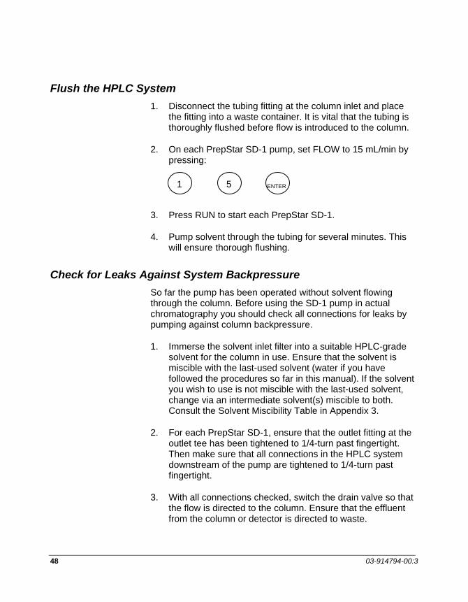
48 03-914794-00:3
Flush the HPLC System 1. Disconnect the tubing fitting at the column inlet and place
the fitting into a waste container. It is vital that the tubing is thoroughly flushed before flow is introduced to the column.
2. On each PrepStar SD-1 pump, set FLOW to 15 mL/min by pressing:
3. Press RUN to start each PrepStar SD-1.
4. Pump solvent through the tubing for several minutes. This will ensure thorough flushing.
Check for Leaks Against System Backpressure So far the pump has been operated without solvent flowing through the column. Before using the SD-1 pump in actual chromatography you should check all connections for leaks by pumping against column backpressure.
1. Immerse the solvent inlet filter into a suitable HPLC-grade solvent for the column in use. Ensure that the solvent is miscible with the last-used solvent (water if you have followed the procedures so far in this manual). If the solvent you wish to use is not miscible with the last-used solvent, change via an intermediate solvent(s) miscible to both. Consult the Solvent Miscibility Table in Appendix 3.
2. For each PrepStar SD-1, ensure that the outlet fitting at the outlet tee has been tightened to 1/4-turn past fingertight. Then make sure that all connections in the HPLC system downstream of the pump are tightened to 1/4-turn past fingertight.
3. With all connections checked, switch the drain valve so that the flow is directed to the column. Ensure that the effluent from the column or detector is directed to waste.
ENTER1 5

OPERATION
PrepStar SD-1 49
4. Set the medium flow rate (10 mL/min for 50 mL/min heads, 40 mL/min for 200 mL/min heads, 200 mL/min for 500 mL heads, 160 mL/min for 800 mL/min heads, or 640 mL/min for 3.2 L/min heads.
5. Press to move the cursor to the TIME field.
6. Set the ramp time to 30 seconds. Press:
7. Press RUN to start the PrepStar SD-1. You will see the Flow and Pressure values on the top line of the display increase.
8. Check all fittings for leaks, especially at the outlet check valves and outlet tee. If no leaks are seen, let the pump continue for several minutes and then stop flow.
9. If you notice any leaks, stop the pump(s) by pressing the STOP button. Tighten the affected fitting by 1/8-turn, and start the pump again. If the fitting still leaks, slow the pump(s) to a low flow rate and tighten the fitting by another 1/8 turn. Continue in this manner until the fitting no longer leaks. It is important not to overtighten the fitting. Tighten in small steps as described.
Setting Flow and Maximum Pressure
Power Up 1. On each PrepStar SD-1 pump, press the ON/OFF switch.
After a few moments the FLOW screen below is displayed.
0 mL/M 0 psiTIME FLOW10.00 -0.50-
ENTER5 •

50 03-914794-00:3
2. Set the desired flow rate and ramp time as described in Initial Set up.
It is important to note that any of the control displays on the PrepStar SD-1 can be accessed at any time by pressing the appropriate button, even while the pump is pumping or ramping to a new flow rate. You do not have to stop the pump to see the pressure display, or the service log display, and so on. PrepStar SD-1 displays are described in Instrument Description.
Setting Maximum Pressure In the PrepStar SD-1, the maximum pressure control can be programmed to either stop the pump or limit the flow when the set pressure is reached. The minimum pressure below which the pump will stop can also be programmed. To set the maximum and minimum pressure:
1. Press the PRESSURE key:
MAX P1500
MAX P100
ACTIONlimit
UNITSpsi
0.00 mL/m 0 psi
2. The cursor should be on the MAX P value. Set an appropriate maximum pressure for your HPLC column using the numeric entry keys and the ENTER key. If you make a mistake or want to change maximum pressure, simply enter the correct value.
When using very high flow rates (greater than 75% of the head size) with the 200, 500 and 800 mL/min liquid heads, the maximum pressure will be limited (see Appendix 5). If you set MAX P in this window too high, an alert message will display the maximum pressure available with the flow rate set.
3. Move the cursor to the ACTION field with the right arrow key and select the action required (limit or stop) by using the down arrow key.

OPERATION
PrepStar SD-1 51
“Stop” will stop the PrepStar SD-1. “Limit” will automatically reduce the flow from the set level to prevent the pressure limit from being exceeded.
NOTE: For Good Laboratory Practices (GLP) and gradient operation it is recommended to use “Stop” for the Max Pressure action. A Stop signal from the Max Pressure action will stop the run and the pressure limit situation will be recorded. If “Limit” were used for the Max Pressure action, the run would continue with no recorded warning for the limit action. Composition would be unreliable in this situation.
4. Move the cursor to the MIN P setting and set the minimum pressure to a value below which you want the pumps to stop. It is good safety practice to use this feature. If the system develops a leak or the solvent reservoir runs dry, the pumps will stop.
5. Move the cursor to the UNITS field if you wish to change the pressure units. Scroll through the units with using the down arrow key. The units are: psi, bar, and MPa. (Set the same units in Dynamax DA when using Dynamax Method Manager to control the pumps.)
6. Part of this window is hidden to the right; it can be reached by pressing the right arrow key. ANALOG PRESSURE MONITOR ON/OFF allows you to send an analog pressure signal to a suitable device such as a chart recorder. (Not available when using Dynamax HPLC Method Manager to control the pumping system.)
Changing the Liquid Heads Four sizes of liquid head are available, allowing the PrepStar SD-1 to be used for all HPLC applications from micro-analytical through full-scale preparative separations.
The PrepStar SD-1 is supplied with the liquid heads installed as ordered. Additional head sets are available in pairs, in the following sizes (refer to the Appendix).

52 03-914794-00:3
Head Size Flow Rate Range Maximum Pressure
50 mL/min (ss) 0.002 – 50 mL/min 10,000 psi (stainless steel)
50 mL/min (Ti) 0.002 – 50 mL/min 6,000 psi (titanium)
200 mL/min 0.01 – 200 mL/min 6,000 psi
500 mL/min 0.02 – 500 mL/min 2,500 psi
800 mL/min 0.02 – 800 mL/min 1,500 psi
3.2L/min 0.1 – 3200 mL/min 375 psi
Interchangeable liquid head sets are supplied assembled and pre-plumbed, and consist of:
2 liquid heads inlet and outlet tubing 2 inlet check valves inlet tee 2 outlet check valves outlet tee
Interchangeable liquid head sets may also require changes to the software.
50 mL/min, 200 mL/min and 800 mL/min all software revisions 500 mL/min Rev 2.0.N or above 3.2 L/min Rev 2.1.G or above
(10000 psi = 685 bar) (6000 psi = 410 bar) (2500 psi = 171 bar)
(1500 psi = 103 bar) (375 psi = 25 bar)
Liquid Head Removal For this procedure you will need two open-ended wrenches (5/16 inch/.312 cm and 1/2 inch) and three T-handle hex wrenches (9/64-inch, 5/32-inch, and 3/16-inch).
1. Stop the PrepStar SD-1 by pressing the STOP key. Do not switch off the PrepStar SD-1; power must be ON for the heads to be removed. Release pressure from the HPLC systems by opening the drain valve.

OPERATION
PrepStar SD-1 53
2. Press ~ to open the SPECIAL DISPLAY:
3. Press to access the setup functions shown below.
0.00 mL/m 0 psi
HEADSCHANGE ID
DEVICE#PUMP CIM
SET CLOCKMM/DD/YY HH:MM:SS
4. With the cursor on HEADS CHANGE / NO, press . NO will scroll to YES:
DO YOU WISH TO ENGAGE THE HEADS? Press ENTER if YES, CLEAR if NO.
5. Press ENTER
to confirm head removal.
The following message will be displayed:
WARNINGREMOVE MOUNTING SCREWS, TUBING
AND CONNECTORSPress ENTER when done, CLEAR to exit.
The liquid heads can be removed as a complete assembly. Or if you prefer you can disconnect the tubing from the inlet and outlet check valves.

54 03-914794-00:3
Layer 1200
Ti200
200200
Ti200Ti
SEEDETAIL
LOCATION OF MOUNTING SCREWS
KNURLEDCOLLAR ALIGNMENT
MARK
DETAIL OF PRESSURE SIGNALCABLE CONNECTOR
REMOVE THESE FITTINGS TOACCESS MOUNTING SCREWSRemove these fittings toaccess mounting screws.
Detail of pressure signalcable connector
KnurledCollar Alignment
Mark
Location of mounting screws
See Detail
Figure 17 Liquid Head Set
6. First remove the high pressure fitting at the outlet tee using a 5/16-inch open-ended wrench. Cap the outlet tee with the cap you removed during initial installation.
7. With a 1/2-inch open-ended wrench, loosen and remove the solvent inlet fitting at the inlet tee, and cap the inlet tee with the cap you removed during initial installation. Then remove the other two fittings in the inlet tee, for access to the mounting screws. Leave the tubing attached to the inlet check valves.
8. Disconnect each pressure signal cable from the socket on the front panel by grasping the knurled collar and pulling back gently. You will feel a slight “give” as the spring-loaded ring is pulled back, then the connector will disengage. If you do not pull back the knurled collar the cable will remain in place. DO NOT PULL THE CABLE or any part of the connector except the knurled ring.
9. With a 9/64-inch T-handle hex wrench, loosen and remove the two mounting screws in the outlet tee. Put the mounting screws aside for mounting the replacement head set.
10. With a 5/32-inch T-handle hex wrench, loosen and remove the two mounting screws in the inlet tee. Put the mounting screws aside for mounting the replacement head set.

OPERATION
PrepStar SD-1 55
11. With a 3/16-inch T-handle hex wrench, loosen and remove the two mounting screws in both liquid heads. Put the mounting screws aside for mounting the replacement head set.
Preparation is complete. Now the PrepStar SD-1 software will disengage the heads.
12. Press ENTER to confirm removal of mounting screws.
After pressing ENTER, the PrepStar SD-1 will start the disengagement sequence. One at a time the liquid heads will be pushed out from the front panel. Support the weight of the liquid heads during disengagement.
When the heads are fully disengaged, the display will read as follows:
HEADS DISENGAGED. REMOVE AND REPLACE Press ENTER when completed.
13. Remove each head by pulling it away from the front panel. You will have to overcome slight resistance from the spring in the collet.
At the same time, remove the inlet and outlet tees. Put the complete assembly aside.

56 03-914794-00:3
Liquid Head Replacement 1. Take the replacement liquid head set assembly and hold
both heads in position, with the piston cups inside the open piston collets. See diagram below.
COLLET
PISTON CUP
2. Press ENTER to begin the liquid head engagement sequence.
The collets will close over the piston cups and when fully closed will draw the liquid heads into place. When both liquid heads are in place the display will read:
REPLACE AND TIGHTEN SCREWS ON BOTH HEADS.PLUMB CONNECTIONS
Press ENTER when completed.
3. Replace and tighten the mounting screws in each liquid head with the 3/16" hex wrench.
4. Replace and tighten the mounting screws in the inlet tee with the 5/32" hex wrench.
5. Replace and tighten the mounting screws in the outlet tee with the 9/64" hex wrench.
6. Replace the low pressure inlet fitting in the inlet tee with the 1/2" open-ended wrench and tighten 1/4-turn past fingertight. Connect the inlet tubing (tee to inlet check valves).
7. Replace the high pressure outlet fitting in the outlet tee with the 5/16" open-ended wrench and tighten 1/4-turn past fingertight.

OPERATION
PrepStar SD-1 57
WARNING
Damage to the pump and possible personal injury may occur if the pump is operated with liquid heads not properly mounted.
The PrepStar SD-1 software cannot tell whether or not you have actually replaced the mounting screws. It is extremely important that the mounting screws are properly attached before attempting to operate the PrepStar SD-1.
8. Press ENTER to confirm the mounting screws and plumbing are connected.
When you have done this the display will read:
PLUG IN BOTH CONNECTORS
Press ENTER when Completed.
9. Reconnect the pressure signal cables.
Press ENTER to complete the head replacement procedure.
If you do not connect the pressure cable, the software will not let you proceed until you have done so.
The display will read (with appropriate values for the actual head size):

58 03-914794-00:3
Remote Operation This section provides a brief introduction to remote control by Dynamax HPLC Method Manager (abbreviated to DMM from now on) or Dynamax PC software.
For complete information you should also read the DMM manual and the Dynamax PC manual.
For remote control:
1. Make the connections between the computer and the PrepStar SD-1 pumps as shown in Figure 5, Figure 6, and Figure 3A. The connections are described fully in Electrical Setup on page 4. Also make connections to the external contacts panel, also described on page 4.
2. For DMM and Star Workstation software to control your pumps, each device must have a unique device ID number. ID numbers are set in the PrepStar SD-1 Set Up display.
3. Press to open the SPECIAL display, and press to open the Set Up display.
3. The ID numbers are shown on the bottom line, in this case Pump ID, 1 and CIM ID, 8. Set these numbers as desired by scrolling with the up/down arrow keys.
NOTE: If you have two pumps, for DMM or Dynamax PC, only one of the built-in CIM (Control Interface Modules) should be used. Set the second CIM ID number to – –, first enter a 63, then push the vertical arrow key. Internal CIM ID number is set only when the internal CIM is used to start data collection or another instrument.
∼

OPERATION
PrepStar SD-1 59
4. When you have set ID numbers for all devices in your system, open Dynamax DA and pull down the System menu. Select Device Status and observe the display on the Macintosh.
5. All devices should be displayed in the positions you allocated when setting ID numbers.
6. Still in Dynamax DA, open the System menu again and select Set Up. A similar window to the one shown will open:
Figure 18 Dynamax DA System Set Up Window
7. Edit the values in this window to correspond to your HPLC system. It is important to enter the correct pump head sizes at the left of the window. Click the mouse button on the up/down arrows to scroll through the preset values until the actual head size of the liquid heads fitted to your PrepStar SD-1 is shown.
When this window is set for your system, click the OK button.
The PrepStar SD-1 is now ready for remote operation by Dynamax HPLC Method Manager. You will probably have to make further electrical connections, depending upon your

60 03-914794-00:3
particular system requirements, e.g., connections for wavelength control of Dynamax UV-1 detector, fraction collector contacts out, and so on. Refer to the Dynamax HPLC Method Manager manual for more information.

PrepStar SD-1 61
Maintenance and Troubleshooting Maintenance
PrepStar SD-1 has been carefully designed with continuous, unattended operation in mind. Rugged construction and sophisticated electronics mean a minimum of routine maintenance and years of trouble-free service if treated carefully and if replacement parts are changed when they show signs of wear. This section of the manual describes service logs, changing the piston seals and changing the check valves.
Service Logs Software in the PrepStar SD-1 automatically tracks seal wear, check valve use, and pump drive wear. The software also allows the user to record seal and check valve changes. Three service log displays are provided:
50.00 mL/m 1500 psi
PISTON SEAL LOG DISPLAY
SEAL LOG DATE LIMITUSE CHANGED1 2/4/92 04 NO
Seal Log: Sequential number of last seal change. Date: Date of last seal change. Use: Use units since last seal change, proportional to
number of strokes and pump pressure. Limit: Use units limit set by user, depending on anticipated
amount of use. Changed: Enter YES when seal change is performed.

62 03-914794-00:3
50.00 mL/m 1500 psi
CHECK VALVE LOG DISPLAY
CV LOG DATE LIMITUSE SERVICED?1 3/12/94 01 YES
CV Log: Sequential number of last check valve service. Date: Date of last check valve service. Use: Use units since last check valve service. Limit: Use units set by user, depending on anticipated
amount of use. Serviced? Enter YES when check valve is serviced.
50.00 mL/m 1500 psi
PUMP DRIVE LOG DISPLAY
DRIVE: W FACTOR K/CYCLES HOURS1.47 19 25
Wear factor: Proportional to pressure. K/Cycles: Number of piston strokes/1000. Hours: Cumulative hours pump has been operating.
Seal Replacement Seals need to be replaced every so often because friction from the moving pistons causes the seals to wear. Seal wear is accelerated under adverse conditions, such as pumping at a high flow rate or pressure, pumping aqueous solutions, or dirty or contaminated mobile phase. More gentle operation (low flow, low pressure, organic solutions, fresh clean HPLC-grade mobile phases) will result in longer seal life. However, every seal will eventually need replacing. Software in the PrepStar SD-1 allows you to both check the seal wear and to log when the seals are changed.

MAINTENANCE AND TROUBLESHOOTING
PrepStar SD-1 63
Each liquid head in the PrepStar SD-1 has one high-pressure piston seal, one washing section seal, and one o-ring. These parts are shown in the exploded view of the liquid head assembly. The illustration shows a 50 mL/min head. Seals for the 200 and 800 mL/min heads are similar but larger.
BACKING DISK
PISTON
WASHING SECTION
HIGH-PRESSURE SEAL
LIQUID HEAD
PRESSURE SIGNAL CABLE CONNECTOR
O-RING
WASHINGSECTION SEAL
PRESSURESIGNALCABLE
SOCKET
SD-1FRONTPANEL
FRONT PLATE
Figure 19 Liquid Head Exploded View (50 mL/min head shown)
Seals and o-rings are supplied in pairs. Both high pressure seals should be replaced at the same time, both washing section seals should be replaced at the same time, and both o-rings should be replaced at the same time. However, you do not have to replace different types of seal at the same time. For example, it is not necessary to replace the o-ring because you are changing the washing section seal. Seals will wear at different rates: in general, you will need to replace the high-pressure seals more often than the washing section seals or the o-rings.

64 03-914794-00:3
To replace seals you need a 3/16” T-handle hex wrench and replacement seals from the list below:
Head Size 50 mL/min 200 mL/min 500 mL/min 800 mL/min 3.2L/min High pressure seals (2)
R0-071056-50 R0-071056-20 R0-071055-60 R0-071056-80 R0-071057-34
Washing section seals (2)
R0-071056-51 R0-071056-21 R0-071055-62 R0-071056-81 R0-071057-33
O-rings (2) R0-071056-22 R0-071056-22 R0-071056-22 R0-071056-82 R0-025350-45 Seal kit containing 2 high pressure seals, 2 washing seals, 2 o-rings
R0-071056-55 R0-071056-25 R0-071057-29 R0-071056-85 No kit exists. Purchase the above parts individually.
You do not need to remove the liquid heads from the front panel to change seals or o-rings but you must remove the fittings at the outlet and inlet check valves. It is recommended that you complete the seal change (or o-ring change) on one liquid head before beginning on the other liquid head. The procedure below is for one liquid head.
Dismantling the Liquid Head 1. Remove the fittings from the outlet and inlet check valves.
2. Remove the pressure signal cable connector by pulling back on the knurled ring. Do not pull on the cable itself.
3. Insert the hex wrench into one of the screw holes in the 3 o’clock and 9 o’clock positions at the front plate of the liquid head. The wrench will stop against the mounting screw.

MAINTENANCE AND TROUBLESHOOTING
PrepStar SD-1 65
200TI
Figure 20 Location of Mounting Screws
4. Turn the wrench gently until you feel it engage the socket in the mounting screw.
5. The mounting screw is a tight fit. When the hex wrench is engaged in the socket, sharply turn the wrench a small amount counter-clockwise to begin loosening the mounting screw.
6. Move to the other mounting screw and repeat steps 4 and 5.
CAUTIONOn the 50 mL/min liquid head it is very important to support the weight of the liquid head body as you remove the mounting screws. If unsupported, the weight of the liquid head body could break the piston
7. Hold the liquid head body and fully loosen both mounting screws–about 9 full turns for each mounting screw. The mounting screws will remain captive behind the front plate.
8. Still supporting the weight of the liquid head, carefully slide the liquid head body straight out from the pump until it clears the piston. Do not apply any sideways or up and down pressure to the piston while removing the liquid head.
9. Carefully slide the washing section off the piston while you support its weight. Do not dismantle the liquid head assembly any further; the backing disk should remain in place.
Mounting screw holes
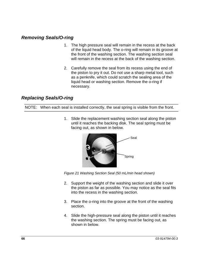
66 03-914794-00:3
Removing Seals/O-ring 1. The high pressure seal will remain in the recess at the back
of the liquid head body. The o-ring will remain in its groove at the front of the washing section. The washing section seal will remain in the recess at the back of the washing section.
2. Carefully remove the seal from its recess using the end of the piston to pry it out. Do not use a sharp metal tool, such as a penknife, which could scratch the sealing area of the liquid head or washing section. Remove the o-ring if necessary.
Replacing Seals/O-ring
NOTE: When each seal is installed correctly, the seal spring is visible from the front.
1. Slide the replacement washing section seal along the piston until it reaches the backing disk. The seal spring must be facing out, as shown in below.
Figure 21 Washing Section Seal (50 mL/min head shown)
2. Support the weight of the washing section and slide it over the piston as far as possible. You may notice as the seal fits into the recess in the washing section.
3. Place the o-ring into the groove at the front of the washing section.
4. Slide the high-pressure seal along the piston until it reaches the washing section. The spring must be facing out, as shown in below.
Seal
Spring

MAINTENANCE AND TROUBLESHOOTING
PrepStar SD-1 67
Figure 22 O-ring and High Pressure Seal (50 mL/min head shown)
5. Align the liquid head so that the slot at the bottom is lined up with its matching slot in the housing on the front panel (see Figure 19). Supporting the weight of the liquid head, carefully slide it along the piston until it stops.
6. Still holding the liquid head, insert the hex wrench into one of the mounting screw holes and tighten the mounting screw until you feel some resistance. Then tighten the other mounting screw until you feel resistance.
NOTE: It is important to tighten both mounting screws a little at a time until they are both tight.
7. Tighten each mounting screw in turn a little at a time until both screws are tight.
8. Replace the fittings at the outlet and inlet check valves.
9. Repeat the procedure for the other liquid head.
O-Ring
Seal
Spring

68 03-914794-00:3
Piston Replacement Each piston in the PrepStar SD-1 can be replaced, using a replacement kit listed below. Both pistons should be replaced at the same time, unless one of the pistons has been broken or chipped.
R0-071057-06 Piston Replacement Kit, 200 mL/min head
R0-071057-07 Piston Replacement Kit, 800 mL/min head
R0-071057-08 Piston Replacement Kit, 500 mL/min head
R0-071057-07 Piston Replacement Kit, 3.2L/min head
Each kit contains: Piston Assembly, O-ring, Seal, Washing Seal
A piston replacement kit (for 200 mL/min head) is shown. Other kits are similar.
Seal
Washing Seal
Piston Assembly
O-Ring
Figure 23 Piston Replacement Kit
To replace a piston, first disconnect the SD-1 from AC power and remove the liquid head as detailed on page 68. (You do not need to remove the check valves for this procedure.)
Removing the Old Piston Assembly 1. Hold the liquid head body with on hand and insert the hex
wrench into one of the screw holes in the 3 o’clock and 9 o’clock positions at the front plate of the liquid head. The wrench will stop against the mounting screw.

MAINTENANCE AND TROUBLESHOOTING
PrepStar SD-1 69
2. Turn the wrench gently until you feel it engage the socket in the mounting screw.
3. When the hex wrench is engaged in the socket, turn the wrench sharply a small amount counter-clockwise to begin loosening the mounting screw.
4. Move to the other mounting screw and repeat steps 2 and 3.
5. Remove the liquid head (with washing section) from the piston assembly. The old seals and old O-ring will probably remain on the washing section.
6. Carefully slide the washing section away from the liquid head. Remove the backing disk from the old piston assembly.
Installing the New Piston Assembly 1. Take the replacement piston assembly and slide the backing
disk over the piston. Align the holes with the screw holes on the piston assembly. Refer to the photos and instructions in Replacing Seals/O-ring on page 66, and slide the washing seal over the piston.
2. Slide the washing section over the piston and install the new O-ring and seal as shown on page 66.
3. Carefully slide the liquid head over the piston, making sure that the holes are aligned.
4. Using the 3/16” hex wrench, tighten each screw until you feel resistance. Then tighten both screws a little at a time until they are both fully tightened.
5. Repeat this procedure for the other liquid head.
Check Valve Replacement Each liquid head in the PrepStar SD-1 has one inlet check valve and one outlet check valve, as shown.

70 03-914794-00:3
OUTLET CHECK VALVE
INLET CHECK VALVE
PISTON LIQUIDHEAD
Figure 24 Cutaway View of Liquid Head (50 mL/min head shown)
A typical outlet check valve is shown in sectional view in Figure 25. Inlet check valves are similar but are installed on the liquid head the other way up. In both types of valve the check valve cartridge assembly is oriented as shown (also see Figure 27).
CHECKVALVE
HOUSING
WASHER(& CHECK BALLRETAINER)
CHECK VALVECARTRIDGE
WASHER
CHECK BALL
SEAT
Figure 25 Typical Outlet Check Valve

MAINTENANCE AND TROUBLESHOOTING
PrepStar SD-1 71
The retracting piston creates a negative pressure in the piston chamber above the inlet check valve. Mobile phase flows upward past the check ball into the inlet check valve, then into the piston chamber. As soon as the piston starts to move forward, gravity causes the ball in the inlet check valve to seat, preventing mobile phase from flowing back out the inlet check valve. At the same time, a positive pressure is created in the piston chamber which dislodges the outlet check valve check ball. Mobile phase flows upward through the outlet check valve while the piston is moving forward. When the piston retracts again, gravity causes the ball in the outlet check valve to seat, preventing mobile phase flowing back out the outlet check valve, and the cycle is repeated.
Cleaning the Check Valves Occasionally the check valves may require cleaning, especially if you notice any drop in back- pressure. A pressure drop may indicate that one of the check balls has become coated with particulate matter or that a small particle has become lodged on the seat; in either case the check ball will not seat correctly and pressure will be lost.
It may be possible to rectify this problem by pumping 20% nitric acid solution through the pump at a low flow rate for 15–20 minutes to dissolve the contamination and flush it away.
WARNING:CHEMICAL HAZARD
Wear safety glasses and gloves. Observe proper safety precautions when using strong acids.
If this procedure fails to correct the problem you should replace the check valve as described on page 74.
Removing the Check Valves 1. Stop flow and switch off the pump power.
2. Loosen and remove the fittings at the top of the outlet check valves.
3. Loosen and remove the outlet check valves.

72 03-914794-00:3
4. Loosen and remove the fittings at the base of the inlet check valves.
5. Loosen and remove the inlet check valves.
Installing the Check Valve Cartridge This procedure is for use only if the cartridge comes out of the check valve.
NOTE: Cartridges are not user-replaceable; the entire check valve must be replaced.
The check valve cartridges are not firmly fixed into replacement check valves; tightening the check valve into the liquid head fixes the cartridge in place. If a cartridge is removed from the check valve, it must be reinstalled in the same orientation. The following figure shows the cartridge components and Figure 27 shows the orientation for outlet and inlet check valves.
NOTE: Do not disassemble the cartridge. Re-assembly requires strict clean-room conditions and specialized equipment.
1. If the cartridge comes out of the check valve, reinsert it in the orientation shown. The retainer wire called out is ALWAYS at the top of the cartridge.

MAINTENANCE AND TROUBLESHOOTING
PrepStar SD-1 73
WASHER
RETAINERWIRE
CARTRIDGEBODY
CHECK BALL
SEAT
WASHER
Figure 26 Check Valve Cartridge Components
OUTLETCHECK VALVE
INLETCHECK VALVE
Figure 27 Orientation of Check Valve Cartridges
Note the difference between outlet and inlet check valves – the outlet check valve housing is smaller and threads into the top of the liquid head. The cartridge must be in the check valve

74 03-914794-00:3
housing as shown in Figure 27. The check ball must be above the seat in both types of check valve housing so that it will seat by gravity.
Before installation: The check ball retainer wire should be visible at the top of the cartridge.
After installation – Outlet check valve: The wire cannot be seen when the cartridge is correctly installed in the outlet check valve.
After installation - Inlet check valve: The wire can be seen when the cartridge is correctly installed into the inlet check valve.
2. Push the cartridge into place into the check valve housing.
Replacing the Check Valve 3. Carefully thread the replacement check valve into the liquid
head. The smaller outlet check valve fits at the top of the liquid head, and the larger inlet check valve fits at the bottom of the liquid head. Tighten each check valve fingertight for now.
4. Connect the inlet and outlet fittings and tighten them 1/8th turn past fingertight.
5. Switch on the power and start the pump. Pump for a few minutes at moderate pressure and observe the check valve for leaks.
CAUTION
It is very important that you do not overtighten the check valves.
6. If there is a leak, tighten the check valve no more than 1/16th turn and tighten the inlet and outlet fittings 1/8 turn. Observe for leaks again. If there is still a leak from the check valve, tighten it by very small increments until the leak stops. Then finally tighten no more than 1/16th turn past the leak-point. Repeat for all check valves.

MAINTENANCE AND TROUBLESHOOTING
PrepStar SD-1 75
Fuse Replacement If the PrepStar SD-1 does not operate when the power cord is connected and the power switch is on, the fuse(s) may need replacing. Fuses are located in the power module on the back of the PrepStar SD-1, as shown in below.
FUSE HOLDER
POWER CORDRECEPTACLE
APPROX. LOCATION ON SD-1
USE SCREWDRIVER TOPRY SPRING TABUPWARD TO RELEASEFUSE HOLDER
Figure 28 Power Module
To replace the fuse(s)
1. Switch off the pump power and remove the power cord.
2. Use a screwdriver to pry the spring tab open at the base of the fuse holder and release the fuse holder.
3. Pull the fuse holder out and replace the fuse(s) as needed.
WARNING:FIRE HAZARD
For continued protection against fire hazard, be sure to replace fuses only with fuses of the same rating and type.
4. Push the fuse holder in until the spring tab locks into place.
5. Connect the power cord and switch on the power.

76 03-914794-00:3
Troubleshooting Troubleshooting an HPLC system requires a methodical approach to be effective. To correct any given problem you have proceed step-by-step, eliminating each variable in turn before moving to the next. Some problems have more than one cause, and can be difficult to locate and correct. The following guide lists some common pump and HPLC system symptoms, with possible causes and suggested corrective actions. In most cases, you will be able to correct the problem; however, sometimes the symptom will remain after you have tried the corrective action. For assistance call LC Technical Services at 1-800-FOR-HPLC.
“Reading” the Pressure Display The sensitivity of the pressure display is within 10 psi. The pressure display can be used as a diagnostic tool to identify the differences between the following similar symptoms:
• Bubbles in the solvent • Sticking check valve
Both will cause erratic pressure readings.
If you notice pressure fluctuations from zero to several hundred psi when the HPLC system is operating at normal pressure, there is probably a bubble in the liquid head.
To clear a bubble, operate the pump at moderate flow (10% of maximum) with the system pressurized. Loosen the outlet tee fitting (shown below) just enough to make the fitting leak.
WARNING:CHEMICAL HAZARD
Wear safety glasses and gloves for this procedure. Observe proper safety precautions when using strong acids

MAINTENANCE AND TROUBLESHOOTING
PrepStar SD-1 77
OUTLET TEE
CRACK THIS FITTING
You should see solvent sputtering at the fitting as the bubble leaks past the fitting. When the bubble is clear, the sputtering will stop and the solvent will ooze past the fitting. At this point tighten the fitting.
If the fluctuation is much lower, e.g. 10 - 40 psi, a check valve is probably sticking. It may be possible to rectify this problem by pumping 20% nitric acid solution through the pump at a low flow rate for 15–20 minutes to dissolve the contamination and flush it away. If this procedure fails to correct the problem you should replace the check valve as described earlier.
Troubleshooting Guide Symptom Possible cause SUGGESTED CORRECTIVE
ACTION
Display remains off when power applied. No motion sounds heard.
Power cord disconnected, power switched off, fuse blown.
Check the pump is plugged in and switched on. If so, check fuses and replace if necessary (page 75).
Leaks Loose fitting(s)
Worn ferrule or fitting
Piston seal needs replacing
Loose check valve
Tighten all plumbing connections no more than 1/4 turn past fingertight.
Replace fitting and ferrule.
Replace piston seal (see Maintenance and Troubleshooting).
Tighten 1/16th turn past the leak-point.
Barely open this fitting

78 03-914794-00:3
Symptom Possible cause SUGGESTED CORRECTIVE ACTION
No flow or pressure Pump is not operating
Air in pump
Clogged solvent in inlet filter
Check the pump is plugged in and switched on. If so, check the fuses and replace if necessary.
Disconnect outlet fittings. Degas solvent. Divert flow to waste and pump at a high flow rate to prime pump.
Check and replace if necessary.
Low Flow Pump is pressured limiting
Clogged solvent inlet filter
Drain valve leaking
Reset MIN P setting to higher value.
Check and replace if necessary.
Repair leak in drain valve.
Erratic pressure Leak
Air in pump
Check and repair leaks.
Disconnect outlet fittings. Degas solvent. Divert flow to waste and pump at a moderately high flow rate to prime pump.
Air bubble in inlet or outlet tubing
Loose inlet tubing connection
Worn flange in inlet tubing
Loose inlet check valve
Inlet filter partially clogged
Loose outlet tubing connection
Tighten inlet fittings.
Remake inlet tubing flange.
Tighten 1/16” turn past the leak point.
Clean or replace.
Tighten outlet fittings.

MAINTENANCE AND TROUBLESHOOTING
PrepStar SD-1 79
Symptom Possible cause SUGGESTED CORRECTIVE ACTION
HPLC SYSTEM
Noisy baseline Air bubbles through flow cell Degas solvent. Divert flow to waste and pump at a moderately high flow rate to prime pump. Check tubing fittings.
Leak in system plumbing
Contaminated flowcell
Detector lamp failing
Bad grounding
Electronic interference
Localized temperature effects
Check for deposits around fittings and check that all fittings are tight.
Attach a syringe to the flow cell INLET and try to clear blockage by drawing on the syringe. Or attach to OUTLET and backflush to clear blockage by gentle pressure on the syringe. Do not apply pressure to the flowcell inlet.
Check and replace if necessary.
Check all grounding connections on SD-1 and ensure grounded AC power is supplied to all devices in HPLC system.
Check for loose connections. Ensure instruments are not in direct contact with each other or with vibrating parts.
Wrap tubing, column. Remove or cover heat or cooling source.
Drifting baseline Contaminated flow cell
Localized temperature effects
Attach a syringe to the flow cell INLET and try to clear blockage by drawing on the syringe. Or attach to OUTLET and backflush to clear blockage by gentle pressure on the syringe. Do not apply pressure to the flowcell inlet.
Wrap tubing, column. Remove or cover heat or cooling source.
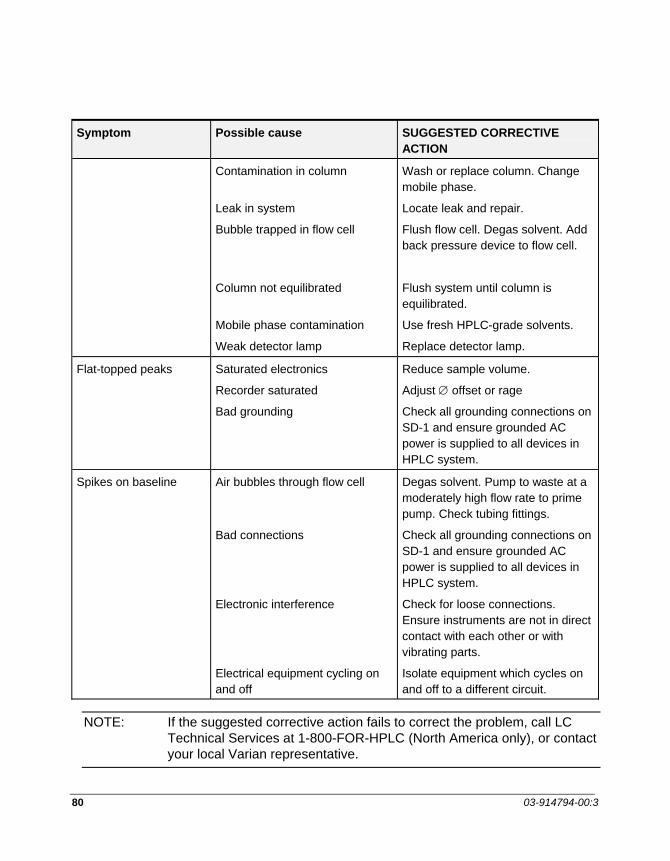
80 03-914794-00:3
Symptom Possible cause SUGGESTED CORRECTIVE ACTION
Contamination in column
Leak in system
Bubble trapped in flow cell
Column not equilibrated
Mobile phase contamination
Weak detector lamp
Wash or replace column. Change mobile phase.
Locate leak and repair.
Flush flow cell. Degas solvent. Add back pressure device to flow cell.
Flush system until column is equilibrated.
Use fresh HPLC-grade solvents.
Replace detector lamp.
Flat-topped peaks Saturated electronics
Recorder saturated
Bad grounding
Reduce sample volume.
Adjust ∅ offset or rage
Check all grounding connections on SD-1 and ensure grounded AC power is supplied to all devices in HPLC system.
Spikes on baseline Air bubbles through flow cell
Bad connections
Electronic interference
Electrical equipment cycling on and off
Degas solvent. Pump to waste at a moderately high flow rate to prime pump. Check tubing fittings.
Check all grounding connections on SD-1 and ensure grounded AC power is supplied to all devices in HPLC system.
Check for loose connections. Ensure instruments are not in direct contact with each other or with vibrating parts.
Isolate equipment which cycles on and off to a different circuit.
NOTE: If the suggested corrective action fails to correct the problem, call LC Technical Services at 1-800-FOR-HPLC (North America only), or contact your local Varian representative.

MAINTENANCE AND TROUBLESHOOTING
PrepStar SD-1 81
Error Messages PUMP STALLED Press any key to continue
NOTE: EFFECTIVE MAX PRESSURE = XXXX AT CURRENT OR SET FLOW RATE Press CLEAR to continue
PUMP MOTOR DRIVE FAILED CALL CUSTOMER SERVICE Press CLEAR to continue
MUST STOP PUMP TO DISENGAGE HEADS Press STOP, or CLEAR to cancel
DISENGAGE FAILED ON HEAD 1. Press ENTER to continue
DISENGAGE FAILED ON HEAD 2. Press ENTER to continue
HEADS DO NOT MATCH. RIGHT HEAD: XXX mL/min, xxxxxx psi LEFT HEAD: XXX mL/min, xxxxxx psi Press ENTER to continue
HEADS DO NOT MATCH. MAXP: XXXXX USED RIGHT HEAD: XXX mL/min, xxxxxx psi LEFT HEAD: XXX mL/min, xxxxxx psi Press ENTER to continue
The messages above are self-explanatory except the Effective Max Pressure message, which tells you that the legal maximum internal pressure is less than you have set in the pressure window. The maximum internal pressure decreases as flow rate increases (Appendix 5).
INVALID MAX= xxxxx, MIN = xxxxx This is the message for an invalid MAXP value. Its value cannot be greater than MAX P for that head nor less the MIN P value.

82 03-914794-00:3

PrepStar SD-1 83
Appendix
Specifications Head Kits:
Part No. Liquid Head Max. Press. Max. Flow Flow Rate Accuracy† Reproducibility‡ R0-071050-60 (SS) 50 mL/min 10,000 psi 50 mL/min ±10 µL/min ± 1.0 µL/min R0-071050-63 (Ti) 50 mL/min 6,000 psi 50 mL/min ±10 µL/min ±1.0 µL/min R0-071050-64 200 mL/min 6,000 psi1 200 mL/min ±10 µL/min ±1.0 µL/min R0-071050-66 500 mL/min 2,500 psi2 500 mL/min ±100 µL/min ±10.0 µL/min R0-071050-65 800 mL/min 1,500 psi3 800 mL/min ±100 µL/min ±10.0 µL/min R0-071050-68 3.2L/min 375 psi3 3.2 L/min ±250 µL/min ±25.0 µL/min
† 1.0% of selected flow rate (all head sizes) or the indicated value for specific sizes ‡ 0.1% of selected flow rate (all head sizes) or the indicated value for specific sizes 1 At flow higher than 150 mL/min the software imposes a linear pressure reduction: 6000 psi at 150 mL/min to 4020 psi at
200 mL/min. 2 At flow higher than 375 mL/min the software imposes a linear pressure reduction: 2500 psi at 375 mL/min to 1675 psi at
500 mL/min. 3 At flow higher than 800 mL/min the software imposes a linear pressure reduction: 1500 psi at 600 mL/min to 600 psi at
800 mL/min.
PUMP MECHANICS Dual piston independent reciprocating linear drive DISPLAY Backlit LCD, 4 lines, 160 characters PRESSURE Psi, bar, or MPa (user selectable) PRESSURE ACCURACY ±5% at 90% full scale, ±10% at 10% of full scale. Full
scale is equal to maximum rated pressure of selected liquid head.
INTERFACE 1 RS-422 digital series input/output channel 6 contact closure relay outputs (1 A, 24 VDC) 5 high-speed CMOS contact closure logic inputs
high: 3.5 VDC to 6.5 VDC low: -1.5 VDC to 1 VDC max. input voltage 25 VDC min. input voltage -20 VDC min. on time for recognition 48.9 ms
1 programmable analog (D to A) output (0 to 10 VDC)

84 03-914794-00:3
12 bits Absolute maximum error ±4.1 mV test load impedance 100 kΩ
2 analog (A to D) inputs (-.5 to 2.5 VDC) 60 Hz max. sample rate combined 6.75 µV per LSB <81.0 µV peak to peak noise at 10 Hz
1 logic level output: 5 VDC pulled up through 47 ohm resistor
OPERATING VOLTAGES 90 - 264 VAC OPERATING FREQUENCies 50 - 60 Hz CPU BOARD VOLTAGES + 5 VDC (4.75 - 5.25 VDC), -15 VDC, +15 VDC, +48
VDC OPERATING TEMPERATURE 4 - 40°C RAM BACKUP BATTERY VOLTAGE
3.1 - 3.3 VDC/Maximum Power Usage: 350 watts
WASHING SECTION Standard on all heads. WEIGHT 34 kg/75 lbs
Dimensions: 10.5-in H x 16-in W x 22-in D
Part Number
Liquid Head
Material in Fluid Contact
Inlet (flat-bottomed)
Outlet (ferrule)
R0-071050-60 (SS) 50 mL/min 316 stainless steel, titanium, sapphire, ruby, FEP, PEEK, Tefzel, UHMWPE, Hastelloy, TXP Zirconia
5/16-24 1/4 -28
R0-071050-63 (Ti) 50 mL/min Titanium, ruby, sapphire, FEP, PEEK Tefzel, UHMWPE, Hastelloy, TZP Zirconia
5/16-24 1/4 -28
R0-071050-64 200 mL/min Titanium, ruby, sapphire, FEP, PEEK Tefzel, UHMWPE, Hastelloy, TZP Zirconia
1/2 - 13 1/4 - 28
R0-071050-66 500 mL/min Titanium, ruby, sapphire, FEP, PEEK Tefzel, UHMWPE, Hastelloy, TZP Zirconia
1/2 -13 1/4 - 28
R0-071050-65 800 mL/min Titanium, ruby, sapphire, FEP, PEEK Tefzel, UHMWPE, Hastelloy, TZP Zirconia
1/2 -13 1/4 - 28
R0-071050-66 3.2L/min* Titanium, ruby, sapphire, FEP, PEEK Tefzel, UHMWPE, Hastelloy, TZP Zirconia
*This fitting is Flaretek 1/2” or 1/4”.

APPENDIX
PrepStar SD-1 85
Maximum Pressure vs. Flow The following diagram shows the maximum pressure/flow curve for each size of liquid head.
Maximum Pressure vs. Flow
375
102015001675
2500
4020
6000
10000
P re s
sure
(ps i
)
00 50 150 200 375 500 600 800 3200
800 mL/Min Heads
3.2L/Min Heads
500 mL/Min Heads
50 mL/Min Heads (Titanium)
50 mL/Min Heads(Stainless)
200 mL/Min Heads
Flow (mL/min)
Accessories
Catalog No. Description R0-00486-01 Prep column hanger for 1/2” column R0-00486-02 Prep column hanger for 1” column R0-04860-2G Prep stand-alone guard hanger 1” R0-00486-04 Prep column hanger for 2” column R0-04860-4G Prep stand-alone guard hanger 2” R0-00486-05 Injection valve bracket R0-00486-06 Prime/purge valve bracket R0-00486-07 Mast clamp R0-00813-98 Mixer “L”-bracket. Required for PrepStar SD-1 R0-00813-99 Mixer mounting bracket 03-935935-91 HPLC tool kit
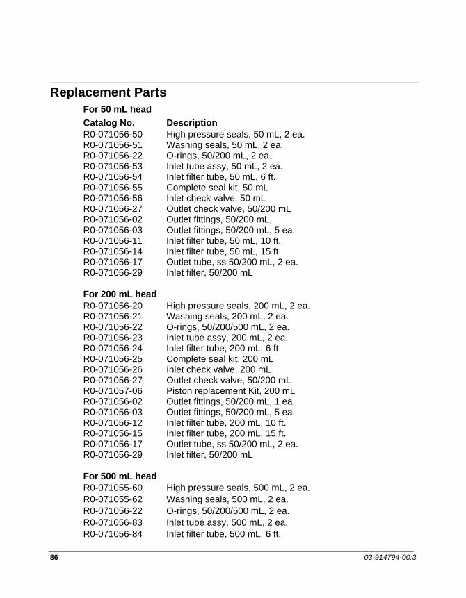
86 03-914794-00:3
Replacement Parts For 50 mL head Catalog No. Description R0-071056-50 High pressure seals, 50 mL, 2 ea. R0-071056-51 Washing seals, 50 mL, 2 ea. R0-071056-22 O-rings, 50/200 mL, 2 ea. R0-071056-53 Inlet tube assy, 50 mL, 2 ea. R0-071056-54 Inlet filter tube, 50 mL, 6 ft. R0-071056-55 Complete seal kit, 50 mL R0-071056-56 Inlet check valve, 50 mL R0-071056-27 Outlet check valve, 50/200 mL R0-071056-02 Outlet fittings, 50/200 mL, R0-071056-03 Outlet fittings, 50/200 mL, 5 ea. R0-071056-11 Inlet filter tube, 50 mL, 10 ft. R0-071056-14 Inlet filter tube, 50 mL, 15 ft. R0-071056-17 Outlet tube, ss 50/200 mL, 2 ea. R0-071056-29 Inlet filter, 50/200 mL For 200 mL head R0-071056-20 High pressure seals, 200 mL, 2 ea. R0-071056-21 Washing seals, 200 mL, 2 ea. R0-071056-22 O-rings, 50/200/500 mL, 2 ea. R0-071056-23 Inlet tube assy, 200 mL, 2 ea. R0-071056-24 Inlet filter tube, 200 mL, 6 ft R0-071056-25 Complete seal kit, 200 mL R0-071056-26 Inlet check valve, 200 mL R0-071056-27 Outlet check valve, 50/200 mL R0-071057-06 Piston replacement Kit, 200 mL R0-071056-02 Outlet fittings, 50/200 mL, 1 ea. R0-071056-03 Outlet fittings, 50/200 mL, 5 ea. R0-071056-12 Inlet filter tube, 200 mL, 10 ft. R0-071056-15 Inlet filter tube, 200 mL, 15 ft. R0-071056-17 Outlet tube, ss 50/200 mL, 2 ea. R0-071056-29 Inlet filter, 50/200 mL For 500 mL head R0-071055-60 High pressure seals, 500 mL, 2 ea. R0-071055-62 Washing seals, 500 mL, 2 ea. R0-071056-22 O-rings, 50/200/500 mL, 2 ea. R0-071056-83 Inlet tube assy, 500 mL, 2 ea. R0-071056-84 Inlet filter tube, 500 mL, 6 ft.
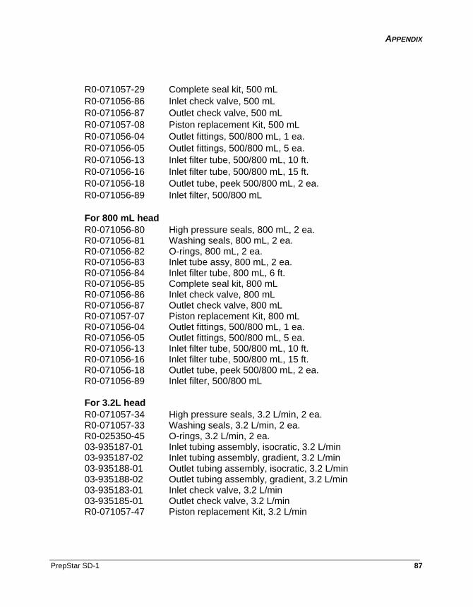
APPENDIX
PrepStar SD-1 87
R0-071057-29 Complete seal kit, 500 mL R0-071056-86 Inlet check valve, 500 mL R0-071056-87 Outlet check valve, 500 mL R0-071057-08 Piston replacement Kit, 500 mL R0-071056-04 Outlet fittings, 500/800 mL, 1 ea. R0-071056-05 Outlet fittings, 500/800 mL, 5 ea. R0-071056-13 Inlet filter tube, 500/800 mL, 10 ft. R0-071056-16 Inlet filter tube, 500/800 mL, 15 ft. R0-071056-18 Outlet tube, peek 500/800 mL, 2 ea. R0-071056-89 Inlet filter, 500/800 mL For 800 mL head R0-071056-80 High pressure seals, 800 mL, 2 ea. R0-071056-81 Washing seals, 800 mL, 2 ea. R0-071056-82 O-rings, 800 mL, 2 ea. R0-071056-83 Inlet tube assy, 800 mL, 2 ea. R0-071056-84 Inlet filter tube, 800 mL, 6 ft. R0-071056-85 Complete seal kit, 800 mL R0-071056-86 Inlet check valve, 800 mL R0-071056-87 Outlet check valve, 800 mL R0-071057-07 Piston replacement Kit, 800 mL R0-071056-04 Outlet fittings, 500/800 mL, 1 ea. R0-071056-05 Outlet fittings, 500/800 mL, 5 ea. R0-071056-13 Inlet filter tube, 500/800 mL, 10 ft. R0-071056-16 Inlet filter tube, 500/800 mL, 15 ft. R0-071056-18 Outlet tube, peek 500/800 mL, 2 ea. R0-071056-89 Inlet filter, 500/800 mL For 3.2L head R0-071057-34 High pressure seals, 3.2 L/min, 2 ea. R0-071057-33 Washing seals, 3.2 L/min, 2 ea. R0-025350-45 O-rings, 3.2 L/min, 2 ea. 03-935187-01 Inlet tubing assembly, isocratic, 3.2 L/min 03-935187-02 Inlet tubing assembly, gradient, 3.2 L/min 03-935188-01 Outlet tubing assembly, isocratic, 3.2 L/min 03-935188-02 Outlet tubing assembly, gradient, 3.2 L/min 03-935183-01 Inlet check valve, 3.2 L/min 03-935185-01 Outlet check valve, 3.2 L/min R0-071057-47 Piston replacement Kit, 3.2 L/min

88 03-914794-00:3
Scale-Up Scientists and manufacturers are frequently faced with the dilemma of completely changing their method of sample purification when switching from analytical to preparative scale.
The PrepStar system was developed to overcome the objections to prep-HPLC with high performance. High performance prep chromatography is accomplished with axial compression preparative (Dynamax®) columns, pulse-free high pressure pumps (PrepStar SD-1) capable of up to 800 mL/min, and a unique UV detector (ProStar 320). Now, both method development and preparative chromatography can be accomplished with 5 µm - 10 µm columns. There is no need to develop two methods and be satisfied with less resolution, capacity and throughput.
System Requirements for High Performance Prep Chromatography
High performance prep chromatography requires long lasting, high efficiency preparative columns and a properly designed HPLC system. Scaling-up HPLC pumps and detectors is not as direct as scaling-up a column. For example, pulsating pumps are common for analytical chromatography, but are not recommended as much for preparative chromatography. Pulsations can affect all columns and they can be largely dampened, but no one wants to potentially decrease the life of a prep column. For preparative columns a pulse-free pump is favored. There are three common ways to make a pulse-free pump. Peristaltic pumps can be used for low pressure, low flow rate applications, but are of little use for preparative chromatography. Syringe pumps will deliver even flow at high temperatures, but high flow rates and pressures for extended periods of time are not obtainable. The most feasible way to develop high pressure, pulses flow with a wide flow range is with a dual piston pump where one starts to pump as the other stops pumping. Using stepper motors with pressure compensation feedback assures constant flow and pressure.

APPENDIX
PrepStar SD-1 89
The pressure capacity for an SD-1 pump with 200 mL/min pump heads at increasing flow rates is presented.
Pres
sure
(psi)
Flow rate (mL/min)
7000
6000
5000
4000
3000
2000
1000
50 100 150 200
Figure 29 Pressure Capacity vs. Flow Rate
A pressure capacity of 6000 psi (410 bar) is maintained up to 150 mL/min where it decreases to 4000 psi (274 bar) by 200 mL/min - more than ample for HPLC.
Not only are high flow and pressure required for prep HPLC, linear flow and adequate mixing are also required for reproducible chromatography of proteins and peptides.
PrepStar SD-1 pump with 200 mL/min heads works well at both high and low flow rates. Figure 30 reveals that excellent flow rate linearity for low flow rates is achieved, and just as important is the excellent flow reproducibility shown in Figure 31 for flow rates from 80 mL/min to 150 mL/min.
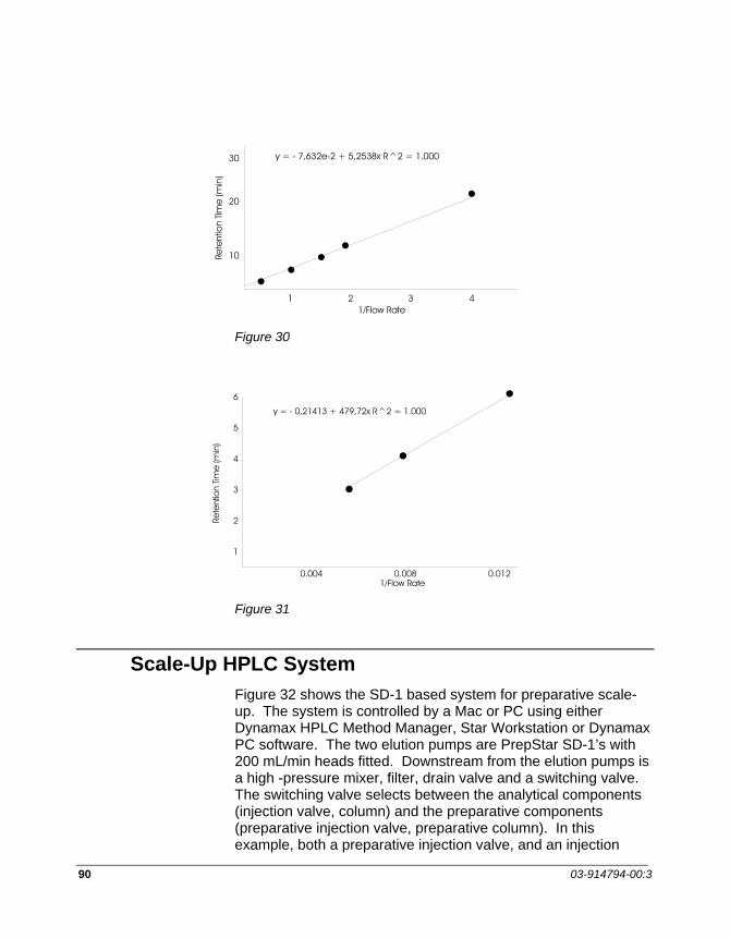
90 03-914794-00:3
30
20
10
1 2 3 41/Flow Rate
Rete
ntio
nTIm
e(m
in)
y = - 7,632e-2 + 5,2538x R^2 = 1.000
Figure 30
Rete
ntio
nTim
e(m
in)
6
5
4
3
2
1
0.004 0.008 0.0121/Flow Rate
y = - 0,21413 + 479,72x R^2 = 1.000
Figure 31
Scale-Up HPLC System Figure 32 shows the SD-1 based system for preparative scale-up. The system is controlled by a Mac or PC using either Dynamax HPLC Method Manager, Star Workstation or Dynamax PC software. The two elution pumps are PrepStar SD-1’s with 200 mL/min heads fitted. Downstream from the elution pumps is a high -pressure mixer, filter, drain valve and a switching valve. The switching valve selects between the analytical components (injection valve, column) and the preparative components (preparative injection valve, preparative column). In this example, both a preparative injection valve, and an injection
APPENDIX
PrepStar SD-1 91
pump are shown - this provides more flexibility. The injection pump is either a ProStar 210/215 with a 50 mL/min head or an equivalent SD-1. The injection pump’s outlet is sent to a tee upstream of the preparative column. The eluent from either column flows to the detector flow cell then to collection.
The Scale-Up Process The HPLC system has all the characteristics necessary to effectively handle both analytical and preparative HPLC with small particle columns.
The next step is to develop a strategy for scale-up from analytical to preparative purifications of protein samples. There are three basic steps to scale-up:
1. Develop the analytical separation method to meet purity requirements.
2. Scale method to maximum load on analytical column
3. Scale flow rate and loading for preparative column with same particle size and column length.
As with all method development, one needs to develop analytical methods which meet purity requirements. For example, there may be a specific contaminant which must be completely removed while other peptides must be lower than some specific level, and specific buffers or salts may be prohibited. Once purity requirements are met with the analytical method, the method is scaled-up to maximum load on the analytical column. Again, knowing purity requirements is very beneficial, since sample displacement with an overloaded column can often provide adequate resolution with greatly increased loading capacity compared to a separation with optimal efficiency. Once the analytical method is perfected, all that is needed is to increase the flow rate and loading by the ratio of the cross-sectional areas. Maintaining the same particle size, linear velocity and proportional load will give the same results with a prep column as with an analytical column.

92 03-914794-00:3
Figure 32 Diagram showing SD-1-based Scale-up System with AutoPrep Option
NOTE: Start and stop of the ProStar 210/215 is controlled by a contact closure which is set up in the external event table in the PC configuration. Connect a cable between the inject and ground of the ProStar 210/215 to a contact closure on the SS-420 board, and a cable between stop and ground of the ProStar 210/215 to another contact closure on the SS-420 board. Set up the trigger of these contact closures at the appropriate time in the external event table. The ProStar 210/215 must not be on the bus or it will limit the maximum flow rate to the maximum allowable system flow rate of the ProStar 210/215.