preparation of road structure durability plans
TRANSCRIPT

Guideline forthePreparationofRoadStructureDurabilityPlans


Table of ContentsExecutive Summary.......................................................................................................................................iii
Glossary..........................................................................................................................................................iv
1 Introduction............................................................................................................................................1-11.1 General..........................................................................................................................................1-11.2 Asset Performance........................................................................................................................1-11.3 Guideline Structure .......................................................................................................................1-11.4 Scope ............................................................................................................................................1-31.5 Submission of Durability Plans .....................................................................................................1-3
2 Content of Durability Plan Report .......................................................................................................2-12.1 General..........................................................................................................................................2-12.2 Overview of Durability Design.......................................................................................................2-12.3 Durability Plan Report Introduction ...............................................................................................2-42.4 Service Life Criteria (Table 1) .......................................................................................................2-5
2.4.1 Structure Components ......................................................................................................2-52.4.2 Durability Limit States .......................................................................................................2-5
2.5 Exposure Conditions (Table 2) .....................................................................................................2-62.5.1 Classification of Environment Conditions in Design Standards........................................2-62.5.2 Macro Environments .........................................................................................................2-72.5.3 Define Deterioration Mechanisms.....................................................................................2-9
2.6 Assessment of Design Solutions (Table 3) ...................................................................................2-92.6.1 Identify Protective or Mitigation Measures......................................................................2-102.6.2 Durability Design in Standards .......................................................................................2-102.6.3 Durability Modelling.........................................................................................................2-102.6.4 Component Inspection & Replacement ..........................................................................2-112.6.5 Detailing ..........................................................................................................................2-112.6.6 DTMR Standards and Standard Details .........................................................................2-132.6.7 Construction Issues ........................................................................................................2-142.6.8 Control of Early Age Thermal Cracking in Concrete ......................................................2-142.6.9 Safety Review of Inspection & Replacement Activities ..................................................2-15
2.7 Maintenance & Servicing Assumptions (Table 4) .......................................................................2-152.8 Routine Inspection (Table 5) .......................................................................................................2-16
2.8.1 Access.............................................................................................................................2-162.8.2 Condition State Guidelines .............................................................................................2-16
2.9 Replacement of Components (Table 6) ......................................................................................2-172.9.1 Bearings ..........................................................................................................................2-17
2.10 Construction Phase Durability Plan Compliance (Table 8).........................................................2-172.10.1 General ...........................................................................................................................2-182.10.2 Durability Critical Processes (Table 8)............................................................................2-182.10.3 Verification Procedures and Tests..................................................................................2-182.10.4 Defects and Treatment Records.....................................................................................2-19
3 Durability Plan Verification Report ......................................................................................................3-13.1 Submission Requirements ............................................................................................................3-13.2 As Built Records............................................................................................................................3-1
3.2.1 Amendments to the design ...............................................................................................3-13.2.2 As Built Drawings..............................................................................................................3-1
Bridge Asset Management, Structures Division Guideline for the Preparation of Road Structure Durability PlansEngineering & Technology
October 2009 i

3.2.3 Construction Records .......................................................................................................3-13.2.4 Durability Verification Report (Table 8).............................................................................3-13.2.5 Level 2 Inspection Report .................................................................................................3-23.2.6 Photographic Records ......................................................................................................3-2
3.3 Materials and Proprietary Product Details (Table 7).....................................................................3-23.3.1 Precast concrete components ..........................................................................................3-23.3.2 Data sheets.......................................................................................................................3-23.3.3 Warranties.........................................................................................................................3-2
4 Durability Design Summary Tables.....................................................................................................4-14.1 General..........................................................................................................................................4-14.2 Structure Durability Outline: Table 1 .............................................................................................4-14.3 Component Exposure Assessment: Table 2.................................................................................4-14.4 Durability Provisions for Critical Components: Table 3.................................................................4-14.5 Maintenance Intervention Assumptions: Table 4 ..........................................................................4-14.6 Inspection & Access Provisions: Table 5......................................................................................4-14.7 Replacement of Components: Table 6 .........................................................................................4-14.8 Proprietary Products Record: Table 7...........................................................................................4-24.9 Construction Phase Departures: Table 8......................................................................................4-24.10 Summary of Submission Requirements........................................................................................4-2
4.10.1 Concept Design ................................................................................................................4-24.10.2 Detailed Design.................................................................................................................4-24.10.3 During Construction ..........................................................................................................4-24.10.4 Construction Verification Report .......................................................................................4-2
5 Reference Documents ..........................................................................................................................5-1
Appendices..................................................................................................................................................A-1Appendix A: Process Flow ChartsAppendix B: Summary TablesAppendix C: Example - Steel StructureAppendix D: Example Concrete StructureAppendix E: Blank Summary Tables
Bridge Asset Management, Structures Division Guideline for the Preparation of Road Structure Durability PlansEngineering & Technology
ii October 2009

Executive SummaryThe Bridge Asset Management Group has developed a series of documents to provide guidance anduniformity of approach to the operation of structures. This document forms part of this programme and setsout the preferred approach for the development and implementation of road structure durability plans fornew construction projects, to enable effective management and maintenance of the structure and achievebetter asset performance.
It is recognised that decisions made at design stage have a profound impact on in-service performance,maintenance intensity and whole of life cost. By requiring designers to consider the materials, designdetailing, construction methods and operational aspects of structures the objective of longer lasting, lowmaintenance structures, that represent a good investment for the State Government of Queensland, can beachieved.
This guideline sets out the requirements for the content of durability plan reports to be prepared by thedesigner and provides the format of summary tables to enable the standardised collation of information. Thedurability plan requirements include:
• the identification of deterioration mechanisms;
• materials selection;
• the development of mitigation measures to ensure that the design intent is met;
• the identification of durability critical construction activities; and
• verification of constructed components to confirm compliance with durability requirements.
To facilitate uniformity in the durability planning process between projects, and assist with the standardisedcollation of information the durability planning process will require the completion of a series of summarytables. These tables must be completed in addition to the preparation of the durability plan report, and willprovide a summary of the:
• durability intent;
• protective measures implemented in the project;
• inspection and maintenance provisions;
• record on going activities during the service life pertaining to durability.
Bridge Asset Management, Structures Division Guideline for the Preparation of Road Structure Durability PlansEngineering & Technology
October 2009 iii

GlossaryTerm Definition
BAM Bridge Asset Management Group.
Bridge and Culvert Servicing Refer to Bridge & Culvert Servicing Manual. Works to prevent damage ordeterioration of a structure that would otherwise be more costly to restore ifleft to progress to structural damage. This includes routine, preventativeand programmed maintenance.
Bridge Rehabilitation This is the restoration of a structure to its original functional performance.The strengthening of bridges to provide a load capacity greater than itsoriginal design is excluded as this should be considered as part of thecapital enhancement programme of works. Typical rehabilitation activitiesinclude deck replacement, pile splicing, timber component replacement,concrete repairs and joint and bearing replacement.
Condition State The condition of component assessed by an accredited inspector inaccordance with the Bridge Inspection Manual.(Condition deteriorating 1 to 4)
Design Life The expected operational life of a structure.
DPR Durability Plan Report.
DTMR Department of Transport and Main Roads.
Durability The ability of materials or structures to resist environmental loads whilemaintaining desired performance parameters.
Periodic Maintenance Planned maintenance over and above those activities undertaken duringroutine servicing.
Preventative Maintenance These are maintenance activities designed to maximise the performanceand longevity of the bridge and its components. Typical activities includethe application of pest and fungal treatments, bearings lubrication,spot/patch repairs to coatings and crack sealing.
Programmed Maintenance This is cyclical maintenance that generally does not apply to structures withthe exception of painting steelwork. However, given the poor state of manyof our steel bridges where a regular painting regime has not beenimplemented, this activity will be initiated within the bridge rehabilitationprogramme when steel bridges are restored to their original condition. (It isacknowledged that this definition is not universally attributed toprogrammed maintenance across the department at this time.)
Routine Maintenance This includes activities that maintain the serviceability of a structure but donot change the condition of the bridge or its components. Typical activitiesinclude clearing of drainage, localised repairs of deck surface, cleaning andadjusting of deck joints, vegetation control and debris removal.
Service Life Expected operational life of the component before failure during which timeit will be able to carry all normal traffic loads, maintain user safety andcomfort, and an acceptable appearance.
Servicing Periodic routine work required to preserve the structure so that it canperform as intended. Activities undertaken are defined in Main RoadsBridge / Culvert Servicing Manual.
Bridge Asset Management, Structures Division Guideline for the Preparation of Road Structure Durability PlansEngineering & Technology
iv October 2009

Part OneIntroduction

Table of Contents1 Introduction............................................................................................................................................1-1
1.1 General..........................................................................................................................................1-11.2 Asset Performance........................................................................................................................1-11.3 Guideline Structure .......................................................................................................................1-11.4 Scope ............................................................................................................................................1-31.5 Submission of Durability Plans .....................................................................................................1-3
List of Figures and TablesFigure 1: Durability Planning Documentation..........................................................................................1-2Figure 2: Submission of Durability Plans ...............................................................................................1-4
Bridge Asset Management, Structures Division Guideline for the Preparation of Road Structure Durability PlansEngineering & Technology Part One - Introduction
1

1 Introduction1.1 GeneralQueensland Department of Transport and Main Roads (DTMR) Bridge Asset Management Section isresponsible for the development and implementation of robust and reliable mechanisms for the inspection,maintenance and operation of the Government of Queensland's bridge and road structure asset portfolio.
To improve the performance of bridge assets and ensure value for money for the Government ofQueensland, the Bridge Asset Management Group (BAM) has developed a series of documents to provideguidance and uniformity in the approach to the operation of structures. This document forms part of thisprogramme and sets out the preferred approach for the development and implementation of road structuredurability plans, to enable effective management and maintenance of the structure and achieve better assetperformance.
Key to an effective asset management programme is the detail and reliability of information available onwhich to plan maintenance and investment programmes. The intention of DTMR's durability plan process isintended to:
1. Integrate structure serviceability performance parameters into the design process, such thatmaterials performance, specifications, construction practices, servicing and maintenancerequirements are considered from the outset. Through this process it is intended that a designphilosophy for structures will be developed that will emphasise lowest whole of life costs, long lifeand low maintenance.
2. Provide a mechanism for the transfer of key maintenance and servicing information between theasset creation stage and the asset operator. The design philosophy for durability greatly influencesthe overall strategy for operation and maintenance of the structure. It is therefore important tohandover pertinent information on the durability approach produced at design phase to theoperator as part of the operation and maintenance manual. The Durability plan provides themechanism to facilitate this.
3. Ensure that consideration is given to hazards associated with inspection and maintenanceactivities, and where practicable, the hazards are eliminated or mitigated through design anddetailing.
1.2 Asset PerformanceKey factors governing how a structure will perform throughout its service life and the total cost of ownershipis greatly influenced by decisions made during the design and construction stages. The approach to ensuredurable performance adopted by the designer will influence how a structure will be maintained, the intensityof maintenance and the total cost of asset ownership.
The objective of the durability guideline is to set out a systematic process to clearly identify how the servicelife will be achieved by thorough consideration of materials, exposure environment, design detailing andmaintenance activities. This will in turn lead to better in service performance of structures that are longlasting and low maintenance. The benefits for long lasting structures will include reduced cost of ownership,reduced disruption to users, increased availability, and improved safety to users and maintenancepersonnel.
Law of Fives“$1 spent getting the structure designed and built correctly, is as effective as $5 spent in subsequentpreventative maintenance in the pre-corrosion phase while carbonation and chlorides are penetrating inwardstowards the steel reinforcement. In addition, this $1 is as effective as $25 spent in repair and maintenancewhen local active corrosion is taking place, and as effective as $125 spent where generalised corrosion istaking place, and where major repairs are necessary and possibly including replacement of completemembers.”W R De Sitter, Costs for Service Life Optimization: The Law of Fives, Durability of Concrete Structures(1984)
Bridge Asset Management, Structures Division Guideline for the Preparation of Road Structure Durability PlansEngineering & Technology Part One - Introduction
October 2009 1-1
1

1.3 Guideline StructureThe retention of relevant information from the asset creation phase through to asset operation andmanagement is an underpinning concept of good asset management. The intent of the durability planningprocess is to gather and record the information generated through the asset creation process, and collate itin a standard format to facilitate consistency of approach to durability planning. Figure 1 shows theproduction of documents relevant to durability planning during the design and construction process and howthese documents are inter-related.
Figure 1: Durability Planning Documentation
Bridge Asset Management, Structures Division Guideline for the Preparation of Road Structure Durability PlansEngineering & Technology Part One - Introduction
1-2 October 2009
1

The guideline is not intended to provide prescriptive solutions, but provide a framework for the designer andconstructor to develop appropriate solutions for the specific structure. A list of reference documentation isprovided to assist with development of durability plans, including DTMR specifications for durabilityplanning. This is not an exhaustive list, but provides a prompt for design details that have been adoptedsuccessfully elsewhere.
A key intent of the durability planning process is the evaluation of standard details and standardspecifications for the situation under consideration. Standard details which work effectively in oneapplication may not be as effect in another. The evaluation process in selecting design details must bethorough and recorded.
To simplify and standardise the presentation of information, tables are provided in the document, whichmust be completed at the appropriate project phase, and submitted as part of the durability plan for reviewby DTMR. The information in these summary tables must be sufficiently detailed to convey the approach toachieving the required durability, as this summary information will be uploaded into DTMR's BridgeInformation System.
The submission of documents, comprising the DPR and summary tables at key milestones in the designprocess will enable DTMR to engage in the durability design process. These tables do not negate the needfor a durability plan report, but are intended as a template to summarise information and act as a prompt forissues to be considered in the durability planning exercise. The report should as a minimum provide thecommentary and explanation of the summary provided in the tables.
The systematic approach to durability planning will provide the starting point for preparation of a structurespecific maintenance manual.
Examples of completed summary tables and example durability plan reports are provided in theAppendices.
Section 2 of this report provides guidance on the content required in the DPR and provides guidance on theissues to be addressed.
Section 3 provides guidance on the content of the Post Construction Durability Plan Verification Report.
Section 4 provides guidance on the completion of the summary tables. These tables are intended to be"live" documents, and as such maintenance activities carried out during the operational life of the structuremust also be recorded. The design and implementation of repair works are recorded in the same way as fornew build works, to ensure that the intended durability is achieved. The implementation of this framework isintended to ensure that cost effective and durable repairs and upgrades are designed and executed.
1.4 ScopeThis guideline covers the preparation of durability plans for the following types of road structures:
• Bridges;
• Culverts; and
• Sign gantries.
The durability planning process outline in this document can equally be applied to other road assets. Thepreparation of durability plans for other road assets, if required, will be stipulated in the contractspecifications.
1.5 Submission of Durability PlansThe consideration of durability issues and development of a strategy to achieve the required service life isintended to be integral with the structural design process. The durability plan report must be prepared by adesigner (the Durability Consultant) experienced in durability design of similar projects. The durabilityconsultant must be named in the concept report and must remain throughout the project.
Durability Plan Reports must be produced at concept and detailed design stages and will form part of thedesign report submissions for review by DTMR. On completion of construction a Durability Plan VerificationReport must be prepared, containing records of product compliance with durability requirements, and noting
Bridge Asset Management, Structures Division Guideline for the Preparation of Road Structure Durability PlansEngineering & Technology Part One - Introduction
October 2009 1-3
1

construction stage departures and any repairs implemented. These durability plans, and associated tableswill also be maintained throughout the service life of the structure and be updated with maintenance andupgrade activities. The DPR's and associated tables will act as a log of all durability related worksundertaken on the structure.
It is intended that the durability plan will be a live document, and will be updated throughout the service lifeand include information on repair and upgrade programmes.
The submission of durability reports for review is envisaged as shown in Figure 2.
Figure 2: Submission of Durability Plans
Deliverable Scope By Whom Reviewed By
Durability Plan Report:Concept Design.
Considers the concept design andenvironmental information and highlightspotential durability issues that will requireconsideration during engineering and detaileddesign process.It includes the development of specific durabilityrequirements for incorporation into materialsupply specifications.Durability Summary Tables 1, 2 and 3.
DurabilityConsultant
DTMR StructuresDivision
Durability Plan Report:Engineering Design.
Considers durability issues of the Engineeringdesign. Where appropriate it includes commentson compliance of design and supplyspecifications with requirements for durability.Highlights durability issues that will requireContractor's consideration and assessmentduring engineering design process.The report will, where appropriate, incorporatecomments on design, specifications,construction method statements and processreview procedures.Durability Summary Tables 1, 2, 3, 4, 5, 6 and 8.
DurabilityConsultant
DTMR StructuresDivision
Durability PlanVerification Report:Construction Stage.
Verification of Quality and Inspection Records inrelation to compliance with requirements ofDurability Plan. Verification of the finished product in relation tothe requirements of Durability Plan.Durability Summary Table 7.
DurabilityConsultant
DTMR StructuresDivision
Durability Plan Report:Repair or Upgradeduring service life.
Considers the durability issues related to themaintenance, repair or upgrade of the structure.The report will, where appropriate incorporatecomments on design specifications andconstruction method statements.Durability Summary Tables 1, 2, 3, 4, 5, 6 and 8.
DurabilityConsultant
DTMR StructuresDivision
Durability PlanVerification Report:Repair or Upgradeduring service life.
Verification of Quality and Inspection Records inrelation to compliance with requirements ofDurability Plan. Verification of the finished product in relation tothe requirements of Durability Plan.Durability Summary Table 7.
DurabilityConsultant
DTMR StructuresDivision
Bridge Asset Management, Structures Division Guideline for the Preparation of Road Structure Durability PlansEngineering & Technology Part One - Introduction
1-4 October 2009
1


Part TwoContent ofDurabilityPlan Report

Table of Contents2 Content of Durability Plan Report .......................................................................................................2-1
2.1 General..........................................................................................................................................2-12.2 Overview of Durability Design.......................................................................................................2-12.3 Durability Plan Report Introduction ...............................................................................................2-42.4 Service Life Criteria (Table 1) .......................................................................................................2-5
2.4.1 Structure Components ......................................................................................................2-52.4.2 Durability Limit States .......................................................................................................2-5
2.5 Exposure Conditions (Table 2) .....................................................................................................2-62.5.1 Classification of Environment Conditions in Design Standards........................................2-62.5.2 Macro Environments .........................................................................................................2-72.5.3 Define Deterioration Mechanisms.....................................................................................2-9
2.6 Assessment of Design Solutions (Table 3) ...................................................................................2-92.6.1 Identify Protective or Mitigation Measures......................................................................2-102.6.2 Durability Design in Standards .......................................................................................2-102.6.3 Durability Modelling.........................................................................................................2-102.6.4 Component Inspection & Replacement ..........................................................................2-112.6.5 Detailing ..........................................................................................................................2-112.6.6 DTMR Standards and Standard Details .........................................................................2-132.6.7 Construction Issues ........................................................................................................2-142.6.8 Control of Early Age Thermal Cracking in Concrete ......................................................2-142.6.9 Safety Review of Inspection & Replacement Activities ..................................................2-15
2.7 Maintenance & Servicing Assumptions (Table 4) .......................................................................2-152.8 Routine Inspection (Table 5) .......................................................................................................2-16
2.8.1 Access.............................................................................................................................2-162.8.2 Condition State Guidelines .............................................................................................2-16
2.9 Replacement of Components (Table 6) ......................................................................................2-172.9.1 Bearings ..........................................................................................................................2-17
2.10 Construction Phase Durability Plan Compliance (Table 8).........................................................2-172.10.1 General ...........................................................................................................................2-182.10.2 Durability Critical Processes (Table 8)............................................................................2-182.10.3 Verification Procedures and Tests..................................................................................2-182.10.4 Defects and Treatment Records.....................................................................................2-19
List of Figures and TablesFigure 3: Durability Design Process Flow Chart .....................................................................................2-3Figure 4: Production of Durability Plan Documents and flow of information through the asset lifecycle.......................................................................................................................2-4Table 2: Example Environmental Classification ......................................................................................2-8
Bridge Asset Management, Structures Division Guideline for the Preparation of Road Structure Durability PlansEngineering & Technology Part Two - Content of Durability Plan Report
2

2 Content of Durability Plan Report2.1 GeneralThe following sections describe the required contents of the Durability Plan Report (DPR). A proposedstructure of the report with suggested headings and the level of detail and issues to be addressed within thenarrative of the report are presented. The exact content and level of detail in the DPR will be dictated by theproject and type of structure under consideration.
The DPR must summarise the approach to achieving the specified design life. The report will provide acommentary on the environmental exposure conditions and how associated deterioration processes areexpected to degrade the structure. Analysis of the rate of deterioration and comparison against the requireddesign life must be provided and what mitigation measures will be used to resist or slow this deterioration.Factors influencing the degradation such as material properties, design details to manage water sheddingand buildability must be considered and documented. For uniformity of presentation of information, and toensure a similar level of detail between projects, standard summary tables have been produced. Thesetables must be completed as part of the durability planning process, and hard copies must be included asan appendix to the DPR. In addition a soft copy of the summary tables must able be submitted.
A typical content of a DPR would comprise sections as follows:
• Introduction
• Service Life Criteria
• Exposure Conditions
• Deterioration Mechanisms
• Assessment of Design Solutions
• Inspection and Maintenance Access Requirements
• Replacement of Components
• Construction Verification Plan
• Service life management of Durability
In addition to the narrative given in the body of the report, the pertinent points of the durability design mustbe summarised in standard tables. These Summary Tables act as prompts from the durability design andmust be completed and included as an appendix to the DPR. Blank tables are provided in Appendix E. Thetables must contain sufficient detail to summarise the selected durability design as described in detail in thetext of the DPR. Completion of the summary tables does not negate the need for the commentary in adurability plan report.
The following sections are intended as guidance on the content of a durability plan report. Particular projectrequirements or conditions may necessitate additional sections as required to be incorporated in thedurability plan report.
Photo 1: Structural Failure due to degradation of timber piers
Bridge Asset Management, Structures Division Guideline for the Preparation of Road Structure Durability PlansEngineering & Technology Part Two - Content of Durability Plan Report
October 2009 2-1
2

2.2 Overview of Durability DesignThe approach to durability design and the provisions to ensure durability set out in current AustralianDesign Codes such as AS 5100 Bridge Design and AS 3600 Concrete Design, may not be adequate toachieve the durability performance that DTMR require. The classification of environments, the effects on astructure and therefore the overall durability are generalised, and may not in any case relate to the designlife specified. Consequently the deemed-to-satisfy approach described in standards and codes, where by aparticular concrete strength and cover are prescribed for a given service life in broadly defined exposureenvironment may not be sufficient to meet the particular performance requirements of the structure. Thedurability design process for DTMR projects must be site and structure specific. The range of deteriorationmechanisms that the structure will be exposed to must be assessed at component level, and appropriateprotective measures designed. In some instances, where a component may be subject to multiple exposurezones, then assessment at a sub component level may be necessary.
Similarly standard details, including DTMR details, must be assessed on a project specific basis forappropriateness, and may need to be modified. This assessment process must be recorded in the DPR, toconfirm that the detail will achieve the intended performance. The slavish application of standard detailswithout a thorough evaluation of the implications on durability is to be avoided.
The approach described below for durability design, sets out a process that is similar to that adopted forstructural design. The load cases for an element are defined, in this case environmental loads, and theelement designed to resist those loads taking into account the potential for progressive degradation. Thedurability design process is schematically shown in Figure 3.
This design process is akin to serviceability limit state design approach to durability. Upper boundperformance limit states are defined for different components, and this is the level of performance to beachieved during the service life.
The durability design process must accurately assess the local environments, identify the relevantdeterioration mechanisms and appropriate mitigation measures. Factors to be included in the assessmentinclude:
• materials,
• design detailing,
• construction method,
• construction quality and
• degree of maintenance.
The durability philosophy adopted must take into consideration all these requirements and be an integralpart of the design process to ensure that opportunities in the design process to adopt a long life lowmaintenance solution are realised. Review of a completed design for durability and inclusion of protectivemeasures, is unlikely to produce an efficient and durable solution.
Bridge Asset Management, Structures Division Guideline for the Preparation of Road Structure Durability PlansEngineering & Technology Part Two - Content of Durability Plan Report
2-2 October 2009
2

Figure 3: Durability Design Process Flow Chart
Figure 4 shows the production of durability planning documents at each stage of the asset creation process.The durability related documents are shown in bold.
The durability plan process outlined in this guideline document will collate information in a systematic andstructured manner to ensure consistency in approach between projects.
Bridge Asset Management, Structures Division Guideline for the Preparation of Road Structure Durability PlansEngineering & Technology Part Two - Content of Durability Plan Report
October 2009 2-3
2

Figure 4: Production of Durability Plan Documents and flow of information through the assetlifecycle
Bridge Asset Management, Structures Division Guideline for the Preparation of Road Structure Durability PlansEngineering & Technology Part Two - Content of Durability Plan Report
2-4 October 2009
2

2.3 Durability Plan Report IntroductionThe Introduction section of the durability plan report should include a brief description of the project and thestructures covered. The durability performance requirements as set out in the scope of work or project briefmust be itemised so that it is clear to all stakeholders that the durability performance of the structure is adefined project outcome. These requirements would typically include broad description of the project designlife, any warranties to be provided and maintenance requirements. The designer will have to interpret whatthe design life would entail for specific components of the structure.
2.4 Service Life Criteria (Table 1)The expected life of the structure is typically specified in the project brief as a design life. This needs to bedeveloped in the service life criteria section of the DPR into the expected service life performance ofindividual components. The components of a structure can have a service life less than the required designlife, necessitating maintenance and replacement. Where practicable, design solutions must be sought thatprovide for long component life and low maintenance.
The durability design process requires that the structure be considered on a sub component basis, asdegradation processes may differ for different parts of a structure. That is the structure must be divided intocomponents and evaluated individually for degradation, in much the same way that elements of thestructure are designed. For example the foundations of a bridge may be exposed to aggressive groundwater below ground while the deck may be in a relatively dry and benign environment. Both components,while fabricated from concrete, may require different mixes, cover and fabrication methods to meet theoverall design life and so must be considered separately.
2.4.1 Structure ComponentsGuidance for the sub-division of the structure into components can be obtained from the DTMR BridgeInspection Manual. In selecting the degree of sub division of the structures into components considerationshould be given to service life, construction materials, method of construction and exposure environment.Further sub-division may be required as the detailed design progresses.
Consideration must be given to the "replaceability" of the component. E.g. piles will need to last the life ofthe structure as it would not be economically feasible to replace them. Conversely hand rails are unlikely toreach the typical 100 years expected of a bridge, without resorting to costly corrosion protection, but can bereadily maintained or replaced and an acceptable maintenance regime and replacement frequency shouldbe considered. The requirements of the DTMR servicing manual for bridges and culverts must be includedin this assessment, as this describes DTMR routine servicing activities. Servicing and maintenancerequirements over and above routine activities must be identified. Specifications for these maintenanceactivities must be developed if required.
Components that are expected to have a service life less than the expected design life of the structure, andtherefore will need to be maintained or replaced one or more times during the design life, must be identified.Protective measures should be evaluated to achieve the required design life with the level of maintenancetypically undertaken by DTMR as detailed in DTMR Bridge servicing manual.
2.4.2 Durability Limit StatesThe designer must elaborate on the general project design life and performance criteria by defining servicelives of individual components.
The definition of the serviceability limit state given in AS 5100 may need to be expanded upon to providesufficient clarity to component serviceability limit state, and will need to take into account the potentialdeterioration mechanisms and the likely dominant mechanism.
AS 5100.1 Bridge Design Clause 6.3.3 which defines serviceability limit states in terms of:
a) Deformation of foundation to give limitation on use or is of public concern.
b) Permanent damage due to corrosion, cracking or fatigue, which significantly reduces the structuralstrength or useful service life of the structure.
c) Vibration leading to structural damage or justifiable public concern.
Bridge Asset Management, Structures Division Guideline for the Preparation of Road Structure Durability PlansEngineering & Technology Part Two - Content of Durability Plan Report
October 2009 2-5
2

d) Flooding damage.
It is critical at this stage that the designer understands and agrees with the client:
• The durability requirements, i.e. service life and what constitutes end of service life
• The expected maintenance and component replacement covering the life of the structure.
Bullet point b) of clause 6.3.3 AS 5100, identifies permanent damage due to corrosion which significantlyreduces structural capacity as a limit state. This definition is subjective. A more robust definition for designpurposes would be that the structure must resist deterioration and expected wear throughout the service lifewithout the need for undue and unplanned maintenance.
In considering the expected service life of a component the governing deterioration mechanism must beidentified and the impact this will have on the component during its service life. The expected visual signs ofdeterioration will drive the criteria for defining the end of life of that component, and determine theserviceability limit state.
The level of acceptable performance required, or more precisely what level of performance is consideredunacceptable, must also be defined in terms that can readily be measured. For example, no cracking due toreinforcement corrosion; no loss of section for structural steel elements; no cracking of elastomericbearings; etc.
The Client requirements for design life of the structure, and the expected serviceability during that life mustbe identified for each major component of the structure. The designer must specifically define the end of lifecriteria i.e. the condition that indicates the end of the service life. In most cases this will align with thecondition state 3 rating defined in the DTMR Bridge Inspection Manual. This in effect is the limit statecondition for the subsequent durability design. These trigger levels, when identified on site will instigatemaintenance activities as detailed in the DPR.
Tabulation of the durability requirements on an element by element basis recognises that the structure hasdifferent components that are exposed to different environments and hence will have different design lives.In addition it recognises that some elements will require planned replacement to achieve the overall life ofthe structure.
Photo 2: Scour of abutment
2.5 Exposure Conditions (Table 2)
2.5.1 Classification of Environment Conditions in Design StandardsThe classification of exposure conditions and the associated durability provisions in the design standardsmust be thoroughly evaluated for applicability as part of this process. AS 5100 provides a globalclassification for the site location relative to the coast line and recommends combinations of concretestrength and cover. Similarly, concrete in contact with aggressive elements in the ground are treated the
Bridge Asset Management, Structures Division Guideline for the Preparation of Road Structure Durability PlansEngineering & Technology Part Two - Content of Durability Plan Report
2-6 October 2009
2

same way, with no evaluation of the concentrations and hence severity of the exposure environment. Thisbroad bush evaluation omits opportunities for efficient design.
The approach to durability design in design codes is suitable for many instances, particularly for simplestructures or benign environments, but has a number of shortfalls. No provision is made for the influence oftotal cement content, water cement ratio or supplementary cementitious materials such as fly ash, silicafume, metakaolin and blast furnace slag to name a few. The incorporation of these and other technologiescan lead to more efficient designs. The global classification of exposure environment, based on proximity tothe coast does not allow for the multiple degradation process that may affect a structure, or may lead toover specification of protection of components. In either case it will result in a costly and inefficient design.
The classification of exposure conditions recognises that environmental loads are site specific and differentcomponents of a structure will also have different performance levels depending on the materials used intheir fabrication. That is, different components of a structure will be subject to different macro environments.
The environmental exposure classifications for each component must be defined in terms of identifying thepresence of aggressive agents and their concentrations, such that severity of exposure can be assessed.E.g. the severity of exposure to a tidal environment can vary depending on chloride concentration, ambienttemperatures, presence of microbial bacteria etc. As a consequence stainless steel in a saline environmentwhere the temperature is typically 20°C, will resist corrosion. The same grade of stainless steel in a salineenvironment where the temperature is 35C or more will corrode. Similarly elements in contact withgroundwater will have different environmental severity depending on the aggressiveness of the groundwater.
The components exposed to the macro environments should be identified. If the environment is aggressivea description of the potential deterioration mechanisms and how the component will degrade must be given.Factors affecting the rate of degradation should also be considered.
The environmental exposure classifications should be summarised in Table 2.
Photo 3: Steel Roller bearings and poor drainage provision on headstock
It is envisaged that the initial classification of potential deterioration mechanisms at concept stage will drivethe site investigation to confirm the presence and concentrations of potentially deleterious agents, enablingthe durability design to be based on site specific data.
Bridge Asset Management, Structures Division Guideline for the Preparation of Road Structure Durability PlansEngineering & Technology Part Two - Content of Durability Plan Report
October 2009 2-7
2

2.5.2 Macro EnvironmentsExposure to aggressive agents, such as chlorides, sulphates, acid sulphate soils and the presence of waterwill act to degrade a structure. A variety of factors will influence how fast these aggressive agents willdegrade a structure, including concentrations, length of exposure period, material properties, temperatureand quality of construction to name a few. Components on a structure, depending on location, will beexposed to a number of different macro environments. Consequently the exposure conditions need to beassessed at a component level. For example an abutment founded on a river bank may be exposed tochlorides below the water table, acid sulphate soils below ground but above water table, splash zone, sprayzone etc. By way of example the following table identifies the classification of environmental loads oncomponents. This list is not exhaustive and the designer is required to assess the site-specific environmentand develop project specific details.
Table 2: Example Environmental Classification
Environment Description Factors that influencedegradation Example
Below ground,permanentlysubmerged.
Components below ground andconstantly submerged
Aggressive compounds inground water.Mobility of ground water.
Foundations, tunnelstructures.
Below ground, abovewater table
Components above thepermanent water table. May besubject to periodic exposure towater due to seasonal variationsin water table.
As above but also wetting anddrying effects.Acid Sulphate soils
Foundations, Tunnelstructures
Permanently submergedbelow water
Component is located below thelowest expect water mark.
Aggressivity of water.Scour and mechanical damageto components
Piles, Foundations,tunnel structures
Intertidal zone Area of the component betweenthe MHHW and MLLW marks.
Salinity.Fresh water flushing.Flooding.
Piles, Piers,Abutments
Splash Zone Area above MHHW that issubject to wetting due tosplashing from boat wash orwave action.
Effect of cyclic wetting anddrying on surface concentrationof aggressive species.Salinity.Flooding.
Piles, Piers, Pile Caps,AbutmentsDeck
Spray Zone Area above the splash zone,subject to deposition of spray.
Prevailing wind direction. Abutments, Piers,deck, Signage
Atmospheric (exposed) Areas exposed to atmosphericweathering. Direct rain orsunlight.
Site specific weather patternsincluding, rainfall andtemperature.Proximity to coastline /Industrial site.Drainage details and watermanagement on and aroundstructure.
Abutments, PiersDeckParapetsBearingsSignage.
Atmospheric (Sheltered) Areas exposed to theatmosphere but sheltered.
Leakage of water, which couldincrease aggressivity ofenvironment.
Inner areas of decksoffit.Bearings.
Bridge Asset Management, Structures Division Guideline for the Preparation of Road Structure Durability PlansEngineering & Technology Part Two - Content of Durability Plan Report
2-8 October 2009
2

The exposure conditions comprise the environmental load case in the durability design process. As suchthe loading must be defined as clearly as possible, and assessed with a factor of safety to allow forvariability as would be the case in structural design. The approach to durability design is not intended tolead to the specification of overly conservative solutions, but to make sure that components at risk ofdeterioration are identified and appropriate protective measures are incorporated. Conversely the durabilityplanning process is intended to eliminate the specification of overly protective measures where they are notrequired.
Photo 4: Chloride induced reinforcement corrosion of columns
2.5.3 Define Deterioration MechanismsCombining the list of components and their design lives with the exposure assessment will highlight a seriesof potential deterioration mechanisms. All should be listed but typically one mechanism is likely to begoverning load case and will dictate the durability design requirements.
A detailed assessment is unlikely to be required for all components, particularly in a benign environment.Conversely, for a critical component or a significant structure, diffusion modelling of chloride ingress, orcarbonation depth calculations may be required to provide confidence that the durability measures adoptedwill achieve the design life.
A durability assessment would typically include but not be limited to:
• Chloride ingress;
• Depth of Carbonation;
• Corrosion of steel components;
• Assessment of concrete mix for resistance to sulphate attack;
• Evaluation of reactivity of aggregates for alkali silica reaction;
• Evaluation of acid sulphate soils risk; and
• Early age thermal modelling and crack risk assessment of critical elements.
There is a wealth of information available on the common degradation processes, and some publicationsare listed in the reference section of this guideline. The parameters influencing the rate of degradation fromsulphate attack, alkali aggregate reaction, carbonation and chloride induced reinforcement corrosion andgeneral steel corrosion are widely known. Specialist advice may be required for degradation due to lesscommon processes, such as microbial induced corrosion.
Bridge Asset Management, Structures Division Guideline for the Preparation of Road Structure Durability PlansEngineering & Technology Part Two - Content of Durability Plan Report
October 2009 2-9
2

2.6 Assessment of Design Solutions (Table 3)
2.6.1 Identify Protective or Mitigation MeasuresThe assessment of the performance and in service degradation of structure components must considersolutions that achieve a low maintenance and long life solution. Where code provisions are assessed asbeing insufficient, additional protective measures must be considered.
The full range of solutions should be considered. Improvements to the resistance to attack of the concretematrix, such as the inclusion of cement replacement materials, low water cement ratios, high range waterreducing agents etc. Activities that are critical to the achievement of the required performance must beidentified. For example the application of early age curing of concrete would be critical to achieving thediffusion characteristics and low permeability envisage by the design. This is particularly critical for mixescontaining fly ash. Poor early age curing can result in a significant reduction in expected diffusion andpermeability characteristics than would be expected if well cured. The required curing regime must bedetailed.
The management of water is an important factor in determining the rate of deterioration of a structure. Thelonger the contact time of water with the structure the greater the risk of corrosion. Protective measuresshould therefore be considered to drain or shed water, or where appropriate seal surfaces withwaterproofing. Damage to expansion joints can result in water penetrating the joint and pooling aroundbearings. Continued exposure to water can lead to corrosion of bearings. Consideration should be given todrainage on the bearing shelf to remove any water leakage. If the structure is in a saline environment,provision of a waterproof membrane should be considered to prevent reinforcement corrosion of the bearingshelf, and thereby mitigate the need for concrete repair works.
For critical elements, where future inspection, repair or replacement may not be possible considerationshould be given to additional protective measures and or measures that will facilitate the laterimplementation of protective measures. E.g. ensuring steel reinforcement continuity during construction tofacilitate the installation of cathodic protection in future. Primary and secondary protective measures shouldbe considered for components that cannot be readily accessed for inspection, maintenance or repair.
Where a specific maintenance regime is required to achieve the service life, and this regime differs fromthat typically adopted by DTMR as described in the Bridge Servicing Manual, this must be described in thedurability Plan report and summarised in Table 4.
2.6.2 Durability Design in StandardsThe provisions for protective measured given in Australian design Standards should be thoroughlyevaluated for the expected exposure environment. The designer should document this evaluation processand determine whether the suggested combination of concrete grade and cover is sufficient to achieve therequisite design life. A "slavish" application of the code requirements may not necessarily achieve therequired durability objective.
Protective measures that are not covered in current design standards and could be considered as part of acorrosion protection strategy include:
• Corrosion Inhibitors• Controlled permeability formwork• Cathodic prevention• Cement replacements such as fly ash, super fine fly ash, blast furnace slag, metakaolin, Micro Silica.• Stainless steel reinforcement• Fibre reinforcement• Surface sealers• Enhanced servicing and maintenance regime.
This list is not intended to be exhausted, but indicates a range of measures available to the designer thatare not prescribed in design codes..
Bridge Asset Management, Structures Division Guideline for the Preparation of Road Structure Durability PlansEngineering & Technology Part Two - Content of Durability Plan Report
2-10 October 2009
2

2.6.3 Durability ModellingIn most cases it is not envisaged that detailed durability modelling using chloride diffusion modelling, asdescribed for example in "Enhancing Reinforced Concrete Durability", (Technical Report 61, ConcreteSociety 2004) will be required. The level of detail required will depend on a number of factors including thecomplexity of the structure, the classification of road carried, and its location. Detailed modelling would berequired for landmark, very long life structures or structures in extremely aggressive environments.
The durability design process requires that an assessment of deterioration rate of a component be made,and if the degradation results in a service life less than the required design life then protective measuresmust be adopted. Where a sufficiently long service life cannot be achieved, even through theimplementation of protective measures, then the design must allow for replacement of the component.
2.6.4 Component Inspection & ReplacementThe designer must consider all the necessary activities in the replacement of a component, and incorporatefeatures into the design to facilitate, safe component replacement. Replacement activities should minimisethe disruption to the operation and use of the structure. In assessing suitability of design solutions, thedesigner must take into account the nature and location of the road, and the implications on congestion oflane closures.
It may be prudent to include primary and secondary protective measures to ensure the durability of acomponent. This would be the case for components that cannot readily be accessed for inspection and orreplacement, or where such activities would result in significant disruption to road users and congestion.
Similarly where access to components for routine condition inspection is restricted or unavailable theinclusion of embedded monitoring probes, such as corrosion ladders or half cells must be considered.
2.6.5 DetailingGood detailing benefits the structure in terms of appearance and durability. Through good detailing ofdrainage and water shedding unsightly staining and degradation can be reduced or eliminated at minimalextra cost. The avoidance of crevices or discontinuities can avoid the ponding of water and build up ofdetritus that can impair structure movement or act as sites for corrosion. Good detailing can also facilitatesafe and thorough inspection and maintenance.
Where DTMR have issued design standards, the designer must evaluate the suitability of the detail for theparticular project conditions, and summarise this evaluation in Table 2.
In developing construction details consideration should be given to the construction process, operation,inspection, maintenance and demolition. While not an exhaustive list the following issues should beconsidered:
• Buildability;
• Drainage and water shedding;
• Access to the bridge for inspection and maintenance;
• Isolation of dissimilar metals to avoid bi-metallic corrosion;
• Reinforcement detailing.
Bridge Asset Management, Structures Division Guideline for the Preparation of Road Structure Durability PlansEngineering & Technology Part Two - Content of Durability Plan Report
October 2009 2-11
2

Photo 5: Corrosion resulting in necking of holding down bolt
i. Water Shedding and Drainage
The presence of water is critical in many deterioration processes. Without water the degradation reactioncan be stopped or its rate severely reduced. Therefore the design should include detailing to ensure thatwater is channelled and discharged away from the structure so that it does not lead to pooling, scour orundermining of components. A structure that is detailed well to prevent pooling of water will typically dryrapidly after wetting preventing the formation of corrosion cells. Poor water management can promote otherassociated degradation mechanisms, such as accumulation of debris, that may seize joints and lead torestraint induced cracking. The prolonged accumulation of debris can result in plant growth which can causestructural damage to components.
Consideration should be given to the water shedding and drainage. Guidance on details that have workedwell is given in Application Guide 33, "Water Management for Durable Bridges", published by TRL. In mostcases the measures likely to be implemented do not require design changes or involve cost increases, butdo require a global assessment of water collation, flow and discharge around and on a structure.
The detailing of structural steel elements must avoid details where water and debris can collect. In additionthe design details must facilitate the application of protective coatings. For instance, components to beprotected by hot dipped galvanising must prevent the accumulation of large zinc deposits at gusset platesthat can in future break off.
Photo 6: Poor drainage detailing leading to corrosion of outer girder and staining on pier.
Bridge Asset Management, Structures Division Guideline for the Preparation of Road Structure Durability PlansEngineering & Technology Part Two - Content of Durability Plan Report
2-12 October 2009
2

ii. Access for Inspection and Maintenance
The designer must ensure that the completed structure allows safe access to the structure for inspectionand maintenance activities. Typically this would entail providing for access to the face of abutments, andproviding a flat level working platform in front of the abutment for inspection, cleaning and bearingreplacement. Sufficient clearance must be provided between the deck soffit and abutment bearing shelf toallow inspection, cleaning and replacement of the bearings.
On critical structures provision of a hard shoulder wide enough to provide working space for inspection andmaintenance activities without the need to close a traffic lane.
Where components cannot readily be accessed for visual inspection then alternative inspection provisionsmust be made. The external reinforcement on a tunnel is at risk of corrosion. The external face cannotreadily be inspected, therefore corrosion monitoring probes should be embedded in the external face andmonitored as part of the structure specific inspection and maintenance plan.
iii. Reinforcement Detailing
In detailing the reinforcement the designer should consider the diameter and spacing of bars, in terms ofconstructability. How will the bars be fixed, and once fixed is the reinforcement cage so congested thatplacing concrete may cause segregation. Can the detailing be amended, for example through the use ofcouplers to eliminate lapped bars. Similarly modifications to construction method such as modifications tothe concrete mix to facilitate placement, through the use of self compacting concrete or use of smallermaximum aggregate size must be considered.
iv. Shrinkage
The designer must consider the implications of long term drying shrinkage and the potential for cracking ofcomponents and the impact on durability. Calculations of expected shrinkage must use the materialproperties of local materials employed on site and not generic shrinkage factors given in codes, which maynot be appropriate.
Assumptions on the expected rate of shrinkage of precast components must be clearly stated in the DPRand the implications for the timing of construction detailed. The design of joints and bearing details mustallow for expected shrinkage of the girders. The premature installation of girders can result in greatershrinkage movements than envisaged in the design resulting in the build up of stresses in the girder and orthe movement of bearings.
v. Bi-Metallic Corrosion
The electrical contact of dissimilar metals that can result in corrosion must be avoided. Where dissimilarmetals are in contact, the surfaces must be insulated to prevent corrosion. This is particularly relevant onbalustrades, lamp posts and sign posts.
2.6.6 DTMR Standards and Standard DetailsThe durability provisions in design codes and DTMR standards must be assessed as to whether they willachieve the project specific durability requirements for the site specific exposure regime. If the measures inthe code are deemed adequate these measures can be adopted without modification. However, if they areinsufficient then additional measures need to be considered. This evaluation process should be recorded inTable 2, and confirms that the designer has considered the applicability of the code requirements for theparticular conditions on the project and verified that they are applicable or otherwise.
Where standard provisions or details are considered inadequate, additional or alternative measures shouldbe proposed as part of the engineering design process for review by DTMR. In justifying the departure fromstandards a review of the inadequacies must be documented and a commentary provided on the alternativedetail provided.
Bridge Asset Management, Structures Division Guideline for the Preparation of Road Structure Durability PlansEngineering & Technology Part Two - Content of Durability Plan Report
October 2009 2-13
2

Photo 7: Inadequate fixity around elastomeric bearing
2.6.7 Construction IssuesThe effectiveness of protective measures is greatly influenced by construction quality, which in turn isinfluenced by method of construction. Therefore a key part of the durability planning process is identifying thekey factors that dictate durable performance and ensuring that appropriate attention is paid duringconstruction to compliance with specification requirements. Any relaxation or amendment to the specificationon site must first be reviewed and approved by the designer to assess the implications on durability.
Components must therefore be checked, following construction, to verify compliance with the durabilityobjective. For example if a steel component is reliant for corrosion protection on a coating, the appliedcoating should be verified to confirm that it was applied with the required dry film thickness, without holidaysand with the required adhesion. As part of the durability planning process the designer must specify whatmeasures will be used to verify compliance with the design intent and incorporate these into the projectdrawings or specifications as appropriate. For example the designer must specify the nominal cover to beprovided to a component, with an allowance for construction tolerance where:
Nominal Cover = Minimum Cover + Construction Tolerance
The compliance criteria would be attainment of the minimum cover, verified by a cover meter survey orsimilar.
Where, owing to the nature of the construction process, good control of the finished product cannot beensured and verified and therefore the effectiveness of the primary protective measure cannot be confirmedthe durability design must take this into account and if necessary secondary protective measuresimplemented. Where on site product verification identifies a deficiency, the extent of any departure from thespecified requirements would need to be assessed by the designer for its impact on the overall durability.Necessary supplementary durability measures or repairs must be implemented to restore the originaldurability intent.
The fabrication and installation processes should be considered at the design phase. For instance theeffectiveness of placing concrete in bored piles will be influenced by the consistency of the concrete mix,which in turn will be dictated by the mix design. A homogenous, well compacted concrete will provide betterdurability performance than one that is segregated. Therefore the specification of the concrete mix mustalso ensure that consistence and cohesion and other factors influencing buildability must be adequatelyaddressed in the specifications. These factors must be described in the durability plan report.
The critical requirements of the durability design solution, such as concrete grade, cover to reinforcementmust be summarised in Table 3.
Bridge Asset Management, Structures Division Guideline for the Preparation of Road Structure Durability PlansEngineering & Technology Part Two - Content of Durability Plan Report
2-14 October 2009
2

2.6.8 Control of Early Age Thermal Cracking in ConcreteThe control of early age thermal cracking in elements influences durability as in many instances durability ispredicated on the protection provided by the cover concrete. Cracking can provide a path for deleteriousagents to by-pass protection offered by the cover and penetrate the body of the concrete. The provision ofreinforcement to control cracking is based on assumptions on potential temperature gradients and theassociated stresses, made at design stage. These assumptions can be different to actual conditions on site.Consideration should be given to the combination of reinforcement, concrete mix properties, ambienttemperatures, construction method, formwork etc and the impact on the likelihood and extent of cracking.
Thermal control of pours to eliminate early age thermal cracking should be considered, particularly foraggressive environments, where cracking of the cover concrete will reduce the durability performance of acomponent. There are a number of methods for modelling expected thermal stresses, which are far morerigorous than the approach in AS 5100. CIRIA C660, Early Age Thermal Crack Control in Concrete,describes one approach. For large or critical pours, consideration should be given to trial mixes andcollation of adiabatic temperature rise data for the preferred concrete mixes. This will enable site specificdata to be used in the assessment of the risk of thermal cracking.
Photo 8: Concrete placement in a pier
2.6.9 Safety Review of Inspection & Replacement ActivitiesDuring the development of the design a safety review should be undertaken that covers the constructionprocess and the operational phase. Inspection, maintenance and component replacement activitiesundertaken on the structure mean that the site is subject to workplace health and safety legislation. As suchthe design review should address features of the design that will reduce the hazards to inspection andmaintenance personnel. This might include provision of safe access from deck level to the abutment tofacilitate activities associated with bearing inspection, cleaning and replacement.
It is envisaged that outline method statements for inspection and maintenance activities will be prepared aspart of the maintenance manual for the structure. The method statement must describe the equipment to beused, and how the activities will be undertaken. Traffic management requirements and access equipmentmust be detailed. Where hazards are identified that are not eliminated by the design these must be clearlyidentified so that the owner is aware of the residual safety risk.
Bridge Asset Management, Structures Division Guideline for the Preparation of Road Structure Durability PlansEngineering & Technology Part Two - Content of Durability Plan Report
October 2009 2-15
2

2.7 Maintenance & Servicing Assumptions (Table 4)To achieve the required service life and appropriate performance level during the service life the structuremust be appropriately maintained.
The maintenance requirements must be identified in terms of a description of the activities to be undertakenand the frequency of those activities. This will enable a review of the appropriateness of the maintenanceactivities and frequency of those activities. The frequency of any maintenance activity will to a large degreebe an assumption, and so the actual performance of a component in service may be better or worse.Therefore a description of the intervention level that would necessitate maintenance should be provided.
The design must be cognisant of the maintenance activities and make appropriate provision for access toenable the works to be carried out safely. Furthermore the access to the structure component must bedetailed in the durability plan and summarised in Table 4. Any traffic management required must also beidentified.
2.8 Routine Inspection (Table 5)
2.8.1 AccessDTMR undertake regular inspections of their bridge structures. Details of the scope and frequency of level1, 2 and 3 inspections are provided in DTMR Bridge Inspection Manual. Inspection requirements identifiedin the design process that are over and above the requirements given in the DTMR bridge inspectionmanual must be detailed in the Durability Plan.
During the life of the structure it will be inspected in accordance with the DTMR inspection manual. Therequirements for access for the various levels of inspection shall be identified and allowed for in the design.Consideration must include, but not be limited to:
• Applicable workplace health and safety requirements;
• Location of access equipment; and
• Traffic control measures.
The inspection regime must consider the nature of the road and the impact of road closures. If inspectionof the structures is likely to be limited to night work, then consideration must given to how this will impactinspection activities and the safety of maintenance personnel.
Routine inspections require visual inspection and in some cases non-destructive testing and sampling. Assuch access to within touching distance of all components of the structure must be provided. While it maynot be practicable to provide permanent access facilities the DPR must identify how inspections will beperformed and the associated hazards. Where safety hazards are not mitigated by the design the hazardsmust be described. A summary of the inspection requirements, access provision and safety hazards mustbe summarised in Table 5 in appendix E. It is recommended that a hazard analysis is undertaken during thedesign process, and the outcomes recorded in Table 5 (Appendix E).
Where elements cannot be inspected directly alternative means of confirming condition must be provided.Where a concrete element is concealed or inaccessible, then provision for assessment of condition may beprovided by the inclusion of permanently embedded half cells (or corrosion ladders to measure thecorrosion potential of reinforcement) connected to accessible test points. Where architectural cladding isprovided, the cladding must be detailed to allow access or removal.
Steel girders forming the support structure to a bridge deck are protected from corrosion by a protectivecoating. The life of this coating would be expected to last 20 years before reapplication, assuming cleaningand patch re-painting as part of the servicing regime. In practice the coating might perform better or worsethan expected. Therefore the trigger level for any intervention must be identified, such that if thedeterioration described was noted during routine inspection then recoating could be applied earlier thanpredicted, of conversely could be delayed. The trigger level for intervention would typically be localisedblistering or peeling of paint or slight rust streaking.
Bridge Asset Management, Structures Division Guideline for the Preparation of Road Structure Durability PlansEngineering & Technology Part Two - Content of Durability Plan Report
2-16 October 2009
2

2.8.2 Condition State GuidelinesThe timing of maintenance or replacement activities will be dependent on in situ performance. Key signsthat trigger the need for maintenance or replacement shall be identified. E.g. appearance of rust spotstriggers the need for spot recoating. This provides the inspection team with a briefing on the expected signsof deterioration, which components are likely to be affected and where to look for deterioration.
2.9 Replacement of Components (Table 6)Components that need to be replaced during the service life of the structure must be identified in Table 6.For each component an expected service life and hence frequency of replacement shall be identified.
The servicing, maintenance and replacement intervention levels must be clearly identified, and summarisedin Table 6. Designers should endeavour to avoid short-life components requiring intensive maintenance orfrequent replacement. Detailing should be such as to promote long service life, with low maintenance, forexample through providing sloped surfaces for self draining and avoidance of dirt and detritus accumulation,and ease of replacement.
Included in the durability report the designer must provide a method statement for the replacement of thecomponent and the provisions in the design.
A hazard assessment must be carried out for the replacement activity and as far as is reasonably practicalthe design should be amended to mitigate or eliminate the hazard. Where a residual hazard remains thisshould be identified clearly so that it can be managed by the relevant organisation undertaking thereplacement works.
2.9.1 BearingsA method statement and drawings for replacement of bearings must be provided. As a minimum thefollowing must be taken into account and documented as part of the durability plan:
• The location of jacking points and size of jack must be detailed on a drawing;
• Temporary loads on the headstock and member being jacked when a bearing is removed forreplacement;
• Provision of sufficient clearance for jacks; and
• Health and safety requirements.
Consideration should also be given to the practicality of restrictions to lane loading during replacementactivities. Lane closures on high traffic structures or structures in urban areas may result in significant trafficcongestion and disruption and therefore should be minimised. Conversely lane or weight restrictions may beacceptable for structures located in rural areas with low traffic volumes.
Photo 9: Detailing of bearing shelf, showing bearing plinths and inspection platform
Bridge Asset Management, Structures Division Guideline for the Preparation of Road Structure Durability PlansEngineering & Technology Part Two - Content of Durability Plan Report
October 2009 2-17
2

2.10 Construction Phase Durability Plan Compliance (Table 8)
2.10.1 GeneralThe overall durability of a structure is influenced by the ability to build it to the required quality and ease ofconducting maintenance activities.
The in service performance of an element will be greatly influenced by the quality of fabrication, which inturn will depend on the ease with which the element can be constructed, the materials used andworkmanship.
Design and construction planning must take into account the problems associated with construction and theconsequences for durability. It is important during construction to ensure that particular attention is paid todurability critical components and inspection and verification procedures focused to ensure the design intentis achieved on site.
The durability plan is intended to provide a documented record of the assumptions on the constructionmethodology for durability critical components made at design stage. Where the method of constructionchanges from that envisaged in the design there may or may not be implications for durability. In eithercase the impact on durability of the construction method should be evaluated by the designer, and ifnecessary appropriate steps taken to ensure durability objective is maintained.
For example, the use of a concrete mix with a high fly ash content may be used to enhance the durability tochloride ingress. In order to achieve the expected performance concrete mixes containing fly ash must bewater cured, and are particularly sensitive to the application of early age curing. Poor curing can result inthe concrete mix having a lower than expected performance. The implications on durability and service lifemust be evaluated by the designer and mitigation measures implemented to ensure that the intendedperformance is achieved.
2.10.2 Durability Critical Processes (Table 8)Critical construction processes identified by the designer must be reviewed by the contractor andappropriate methods of work adopted. As part of this review the contractor must put in place appropriatequality control process to ensure that the assumptions made in design are achieved. This may requireamendments to standard construction practices and standard specification and drawing details. Theseissues must be highlighted to DTMR prior to appropriate amendments being made to specifications.Similarly validation of the components, to confirm that the durability design intent has been met, must alsobe identified. These verification processes, which may include non-destructive testing, must be clear andunambiguous methods of verifying that the component has achieved the expected performance criteria.These validation measures are intended as a mechanism to communicate clearly to the site supervisionteam the importance of certain parameters in achieving durability.
This information must be recorded in the durability plan and included in specifications or drawings.
2.10.3 Verification Procedures and TestsQuality Assurance procedures are typically focused on surveillance of the methods and processes in theproduction of an element, whereas for durability critical components end product compliance is theobjective. Accordingly for durability critical activities this process surveillance must be supplemented with adetailed inspection and test plan (ITP) and product compliance testing.
It is essential to undertake product verification checks to ensure that what has been constructed complieswith the design intent. Testing must as a minimum verify that critical durability parameters have been met.This might include a cover survey of a representative area of a component to confirm minimum coverrequirements have been achieved. Coating verification would include, wet and dry film thicknessmeasurements, adhesion testing and holiday testing.
Any construction defects such as honey combing, cracking in excess of specified allowable crack widthsmust be identified and rectified. It is essential that a durability assessment be conducted, by the designer, inthe determination of the appropriate repair or remediation measure. The location and details of the repairmust be recorded on as built drawings for compilation in the maintenance manual.
Bridge Asset Management, Structures Division Guideline for the Preparation of Road Structure Durability PlansEngineering & Technology Part Two - Content of Durability Plan Report
2-18 October 2009
2

The inspection and product verification must be undertaken as soon as practical after construction.
2.10.4 Defects and Treatment RecordsThe nature of the construction activities means that defects or deviations from the planned and designcomponents will occur. Where this has an implication on durability the remediation work must address anyloss in durability.
Non-Conformance records (NCR) must record the rectification treatment and a comment from the designeron the overall effect on durability.
Defects that occur during construction must be recorded and passed to the asset operator as part of therecord of construction.
Identifying when a defect occurred and how well the repair performs during the service life is important formaintenance planning.
Where a non-conformance or construction departure from the durability requirements is identified, thedesigner must evaluate the implications on performance and whether any further protective measures arerequired to restore the intended durability.
Where there is a reduction in durability, additional protective measures or repairs are required to beundertaken and must be designed or specified by the designer to restore the intended durability. Thisprocess must be recorded, and include the location of any repairs, the materials used and verificationrecords that the repair was carried out to the required standard.
Product VerificationThe implementation of site quality assurance systems may not adequately address the requirements of thedurability design. The designer must therefore identify the key elements of the durability design measuresand describe the verification measures to confirm that these design measures have been achieved on site.These verification measures must be incorporated into the contractor's inspection and test plans for therespective component.Eg. The durability design measure for a pile cap is the provision of a concrete with a maximum w/c ratio,minimum cement content and cover to reinforcement. The effectiveness of this protective measure is relianton the concrete being placed and compacted to achieve an homogenous mix, free of voids, defect andcracks. The placement and compaction of concrete will be influenced by: the concrete mix design; theplacement method; the compaction method; the consistence of the concrete; thermal control of the pour;seasonal climatic conditions and curing. In addition the rigidity of the cage and accuracy of fixing, and anymovement during concrete pouring will influence the final cover achieved.The provision of the correct mix could be verified by inspection of mix dockets, and cylinder strength results.Significant variation in compressive strength either up or down would indicate variation from the approvedmix.To confirm that adequate cover had been provided, a cover meter survey of the component would beundertaken. The pile cap must also be inspected to ensure there are no construction defects such ashoneycombing or cracking. If the curing is suspected of being poorly done, then water absorption testingsuch as initial surface absorption could be instigated.
Bridge Asset Management, Structures Division Guideline for the Preparation of Road Structure Durability PlansEngineering & Technology Part Two - Content of Durability Plan Report
October 2009 2-19
2

Part ThreeDurabilityPlanVerificationReport


Bridge Asset Management, Structures Division Guideline for the Preparation of Road Structure Durability PlansEngineering & Technology Part Three - Durability Plan Verification Report
3
Table of Contents3 Durability Plan Verification Report ......................................................................................................3-1
3.1 Submission Requirements ............................................................................................................3-13.2 As Built Records............................................................................................................................3-1
3.2.1 Amendments to the design ...............................................................................................3-13.2.2 As Built Drawings..............................................................................................................3-13.2.3 Construction Records .......................................................................................................3-13.2.4 Durability Verification Report (Table 8).............................................................................3-13.2.5 Level 2 Inspection Report .................................................................................................3-23.2.6 Photographic Records ......................................................................................................3-2
3.3 Materials and Proprietary Product Details (Table 7).....................................................................3-23.3.1 Precast concrete components ..........................................................................................3-23.3.2 Data sheets.......................................................................................................................3-23.3.3 Warranties.........................................................................................................................3-2

3 Durability Plan Verification Report3.1 Submission RequirementsThe provision of relevant information to the owner and operator of the structure is an important part of theasset management process. This information can be referred to as the birth certificate of the structure anddocuments design issues, construction and condition of the structure at the time of hand over.
The items described below are to be included with all other as-built documentation, and only relate todurability design information to be handed over.
On completion of construction, the designer in conjunction with the contractor must compile the durabilityplan verification report as part of the as built records and hand over documentation.
The durability plan verification report would include an update of the durability plan report incorporating anychanges necessitated during construction records of materials used, construction departures and mitigationmeasures adopted. The updated durability plan summary tables must also be updated to reflect the as builtstructure. If the preparation of a maintenance manual for the structure is a project requirement the summarytables must be included as appendices in the manual. The tables will serve as a concise summary of thedurability intent, how this was achieved and verified, and the required maintenance and inspection activities.These documents will be stored in the DTMR Bridge Information System.
3.2 As Built Records
3.2.1 Amendments to the designWhere site conditions require an amendment to the design, the original designer must be consulted. Anychanges must be recorded on as built records and implications on durability recorded in the durability plan.Where necessary, additional protective measures must be adopted to reinstate the intended durabilityobjective.
3.2.2 As Built DrawingsThe requirements listed below supplement those specified in the contract documentation.
A full set of as built drawings must be included in the maintenance manual. The information must includebut not limited to the following:
• Location of all services;
• Drainage system details;
• Reduced Level of pile toe; and
• Deviation from tolerances of piles, headstocks and bearing pedestals.
The drawings must be provided in both sets of the following formats:
• AutoCAD; and
• Scanned copy in JPG or TIF format.
3.2.3 Construction RecordsThe requirements listed below supplement those specified in the contract documentation. Constructionrecords to be provided in the maintenance manual include:
• Summary of concrete test results;
• Post tensioning records;
• Weld tests;
• Shop drawings; and
• Precast records.
Bridge Asset Management, Structures Division Guideline for the Preparation of Road Structure Durability PlansEngineering & Technology Part Three - Durability Plan Verification Report
October 2009 3-1
3

3.2.4 Durability Verification Report (Table 8)The durability verification report must be updated to reflect changes to the design and constructiondepartures as outlined in section 3.1, 3.2 and 3.3.
Table 8 must be updated to include construction stage departures such that details of the structure actuallyconstructed must be recorded.
3.2.5 Level 2 Inspection ReportAs part of the handover process for the asset a Level 2 inspection, to DTMR standards must be undertakenby an accredited Main Roads Level 2 Inspector. The completed report must be included as part of the assetdocumentation.
3.2.6 Photographic RecordsA full photographic survey of the structure must be undertaken. The photographs should record generalviews of the main structural components, with close up photographs of repaired areas. The photographicrecord provides a snap shot in time of the original condition of the structure. Future condition inspectionscan then be compared against the original records to assess the progression of deterioration.
3.3 Materials and Proprietary Product Details (Table 7)Details of proprietary products or components must be provided. This not only provides a record ofconstruction, but should components need to be investigated or replaced the information pertaining to thereplacement component can readily be obtained. Data sheets pertaining to all proprietary products shouldbe provided as described in 3.3.2.
3.3.1 Precast concrete componentsThe details of precast concrete components, including but not limited to bridge beams, crash barriers,parapets must be provided. These details must include:
• Records of concrete mixes;
• Casting and production records;
• Test certificates for aggregates and cementitious materials;
• Compressive strength results;
• Details of any repairs undertaken;
• Mill certificates for reinforcement of Pre-stressing tendons; and
• Contact details of manufacturer.
These requirements supplement those specified in the contract.
3.3.2 Data sheetsThe data sheets of all materials used must be provided, including:
• Coatings;
• Concrete repair mortar;
• Sealants;
• Movement joints;
• Bearings; and
• Parapet barriers, handrails and balustrades.
In addition for bearings and movement joints, manufacturer's shop drawings must be provided.
The name, address and contact details of the supplier must be provided.
Bridge Asset Management, Structures Division Guideline for the Preparation of Road Structure Durability PlansEngineering & Technology Part Three - Durability Plan Verification Report
3-2 October 2009
3

3.3.3 WarrantiesDetails of any warranties must be provided, along with an original copy of the warranty. The duration of thewarranty and any servicing required to maintain the validity of warranty must be detailed in the servicingrequirements.
Bridge Asset Management, Structures Division Guideline for the Preparation of Road Structure Durability PlansEngineering & Technology Part Three - Durability Plan Verification Report
October 2009 3-3
3

Part FourDurabilityDesignSummaryTables

Bridge Asset Management, Structures Division Guideline for the Preparation of Road Structure Durability PlansEngineering & Technology Part Four - Durability Design Summary Tables
4
Table of Contents4 Durability Design Summary Tables.....................................................................................................4-1
4.1 General..........................................................................................................................................4-14.2 Structure Durability Outline: Table 1 .............................................................................................4-14.3 Component Exposure Assessment: Table 2.................................................................................4-14.4 Durability Provisions for Critical Components: Table 3.................................................................4-14.5 Maintenance Intervention Assumptions: Table 4 ..........................................................................4-14.6 Inspection & Access Provisions: Table 5......................................................................................4-14.7 Replacement of Components: Table 6 .........................................................................................4-14.8 Proprietary Products Record: Table 7...........................................................................................4-24.9 Construction Phase Departures: Table 8......................................................................................4-24.10 Summary of Submission Requirements........................................................................................4-2
4.10.1 Concept Design ................................................................................................................4-24.10.2 Detailed Design.................................................................................................................4-24.10.3 During Construction ..........................................................................................................4-24.10.4 Construction Verification Report .......................................................................................4-2

4 Durability Design Summary Tables4.1 GeneralThe following sections describe the process for completion of the durability design summary tables. Thesetables are intended to summarise, in a succinct manner, the key outcomes and durability design describedin detail in the Durability plan report narrative. A commentary is given on the information that is required tobe completed in the durability plan summary tables and a process flow chart provided in Appendix A.Examples of the completed tables are presented in Appendix B for reference, and blank tables are providedin Appendix E.
Soft copies of the summary tables are to be provided in MS Excel format to facilitate uploading of pertinentdurability and maintenance information into DTMR's bridge management system (BMS). Soft copies of thetables are provided on the disk provided in Appendix F. Consequently additional rows can be added to thespread sheets but the headings are locked. This has been developed to assist in the compilation ofdurability plans through table linkage. Additionally the standard formatting will facilitate the uniform collationof information for uploading into the Bridge Information System.
4.2 Structure Durability Outline: Table 1The expected durability and service life performance of the structure components is summarised in thistable, as derived in accordance with section 2.4.
The table must be completed as part of the concept design, and the contents agreed with DTMR prior toprogressing with detailed design.
4.3 Component Exposure Assessment: Table 2For each component the environmental load case(s) that apply, as derived in accordance with section 2.5must be summarised in Table 2. In many instances a component will be exposed to several differentexposure mechanisms and these must all be identified.
4.4 Durability Provisions for Critical Components: Table 3This table summarises the durability design mitigation measures derived in accordance with section 2.6.
The contents of the first 3 columns of this table, which summarise the exposure and degradationmechanisms on a component basis, are populated as part of Table 2.
4.5 Maintenance Intervention Assumptions: Table 4This table summarises the expected maintenance activities at a component level, derived in accordancewith section 2.7.
The contents of the first 3 columns of this table, which identify the component and exposure conditions, aretransferred from Table 2.
This table must be completed as part of the detailed design process.
4.6 Inspection & Access Provisions: Table 5The contents of this table summarise the access provisions to required to undertaken the maintenanceactivities identified in Table 4, and the access requirements for inspection. These entries are derived inaccordance with sections 2.7 and 2.8 respectively.
4.7 Replacement of Components: Table 6This table summarises the provision for the replacement of components derived in accordance with section2.9.
The first 6 columns of this table collate information from Tables 1 to 5.
Information on the components and exposure conditions are transferred from Table 2.
The replacement frequency is transferred from Table 1.
Bridge Asset Management, Structures Division Guideline for the Preparation of Road Structure Durability PlansEngineering & Technology Part Four - Durability Design Summary Tables
October 2009 4-1
4

The condition state guideline, that describes the trigger point for intervention is transferred from Table 5.The design mitigation measures are transferred from Table 3.
4.8 Proprietary Products Record: Table 7Table 7 summarises the requirements for maintaining proprietary product records in accordance withsection 3.3.
Where proprietary products are specified in the design, the details must be listed. The first 4 columns of thistable must be completed as part of the detailed design. At construction stage the proprietary product maybe changed, and this change must be approved by the designer to ensure that functionality or durabilityperformance is not compromised.
Following construction the warranty details and installation details must be completed. The updated tablewill be included in the Construction Verification Report.
4.9 Construction Phase Departures: Table 8Table 8 summarises the validation of the original durability requirements or approved variations inaccordance with section 2.10. The first 6 columns of this table are populated with data from Tables 2 and 3.The intervention trigger levels must be completed. The remaining columns in the table must be completedduring the construction phase.
4.10 Summary of Submission Requirements
4.10.1 Concept DesignBefore commencing detailed design the durability performance criteria and environmental load cases mustbe agreed with DTMR. A concept durability plan report comprising a narrative of the durability designphilosophy, expected degradation mechanisms must be submitted as part of the concept design report. Thefollowing summary tables must also be completed.
• Table 1 Structure Durability Outline
• Table 2 Component Exposure Assessment
4.10.2 Detailed DesignThe detailed design durability plan report will comprise the narrative with the following tables completed.
• Table 1 Structure Durability Outline (Updated from concept design)
• Table 2 Component Exposure Assessment Updated from concept design
• Table 3 Durability Provisions for Critical Components
• Table 4 Maintenance Intervention Assumptions
• Table 5 Inspection and Access Provisions
• Table 6 Replacement Components
• Table 7 Proprietary Products Records
• Table 8 Durability Provisions for Critical Components
4.10.3 During ConstructionThe results of product verification inspection and testing must be recorded in Table 8 during construction.Where construction departures from the intended design occur the designer must be made aware of thedeparture and evaluate and record the impact on durability performance. Where durability performance hasbeen compromised remedial measures must be implemented to restore the component durability objective.
4.10.4 Construction Verification ReportOn completion of construction the designer must compile a summary of the construction departures and thesubsequent repairs undertaken to restore durability. The defects, repairs and verification records must besummarised in Table 8.
Bridge Asset Management, Structures Division Guideline for the Preparation of Road Structure Durability PlansEngineering & Technology Part Four - Durability Design Summary Tables
4-2 October 2009
4

Marked up drawings showing the location of defects and repairs described in Table 8 must be provided.
Photographic record of all components at hand over must be provided.
• Table 7 Proprietary Products Records (Updated)
• Table 8 Durability Provisions for Critical Components (Updated)
Bridge Asset Management, Structures Division Guideline for the Preparation of Road Structure Durability PlansEngineering & Technology Part Four - Durability Design Summary Tables
October 2009 4-3
4

Part FiveReferenceDocuments


5 Reference DocumentsApplication of the durability provisions given in design codes such as AS 3600 and AS 5100 may notadequately meet the performance requirements for long life low maintenance road structures. As suchguidance on appropriate durability measures should be sought from other sources.
The following list of reference documents are provided as sources of guidance. The list is not exhaustive,nor is all the guidance provided in these documents relevant to the range of exposure environments foundin Australia.
• Concrete in Aggressive Ground, BRE Special Digest 1, 2005
• Early Age Thermal Crack Control in Concrete, Report C660, CIRIA, 2007
• Enhancing Reinforced Concrete Durability, Technical Report 61, Concrete Society 2004.
• Durable Concrete Structures, Recommended Practice, Concrete Institute of Australia, 2001.
• Austroads Standards
• Queensland Department of Transport and Main Roads, Bridge / Culvert Servicing Manual
• Queensland Department of Transport and Main Roads, Bridge Inspection Manual
• Bridge Detailing Guide, Report C543, CIRIA, 2001.
• Bridges - Design for Improved Buildability, Report 155, CIRIA, 1996
• Water management for durable bridges, TRL Application Guide 33, 1998.
Bridge Asset Management, Structures Division Guideline for the Preparation of Road Structure Durability PlansEngineering & Technology Part Five - Reference Documents
October 2009 5-1
5


Appendices


Table of ContentsAppendix A: Process Flow Charts
Appendix B: Summary Tables
Appendix C: Example - Steel Structure
Appendix D: Example Concrete Structure
Appendix E: Blank Summary Tables
Bridge Asset Management, Structures Division Guideline for the Preparation of Road Structure Durability PlansEngineering & Technology Appendices
A

Appendix A: Process Flow Charts
Flowchart - Serviceability limit state design Section Reference in GuidelineDocument
ReferenceTable
2.2 Structure Durability Outline2.4.1 Structure Components2.4.2 Durability Limit States
Table 1
2.5.2 Macro Environments2.5.3 Deterioration Mechanisms
Table 2
2.6 Durability Provisions for CriticalComponent Table 3
2.7 Maintenance Assumptions Table 4
2.8 Routine Inspection Table 5
2.9 Replacement Components Table 6
3.3 Materials and Proprietary ProductDetails Table 7
Bridge Asset Management, Structures Division Guideline for the Preparation of Road Structure Durability PlansEngineering & Technology Appendices
October 2009 A-1
A

Flowchart - Provisions for Durability Critical ConstructionActivities
Section Reference in GuidelineDocument
ReferenceTable
2.6.7 Durability Critical Processes
2.10.3 Verification Procedures andTests
2.10.4 Defects and TreatmentRecords
Table 8
Bridge Asset Management, Structures Division Guideline for the Preparation of Road Structure Durability PlansEngineering & Technology Appendices
A-2 October 2009
A

Appendix B: Summary Tables
Du
rati
on
(years
)
Co
ntr
act
Refe
ren
ce
Po
ten
tialM
od
eo
fF
ailu
reD
ete
rio
rati
on
Mech
an
ism
Fa
cto
rsC
on
tro
llin
gR
ate
of
De
teri
ora
tio
n
En
do
fL
ife
Cri
teri
a(E
xp
ecte
d
go
vern
ing
fail
ure
mech
an
ism
)
Chlo
ride
induced
Carb
onation
induced
Macro
cell
corr
osio
n
Localis
ed
corr
osio
natcra
cks
and
join
ts
Sulfate
attack
of
concre
te.
Sulfate
attack
of
concre
teM
obili
tyof
gro
und
wate
r
Weakenin
gand
ero
sio
nof
concre
tefr
om
acid
sulfate
soils
Degra
dation
of
concre
teand
ste
elfr
om
acid
Degre
eof
oxid
ation
of
PA
SS
and
exte
ntof
AS
S
Ela
sto
meric
Beari
ngs
40
years
Pro
ject
Specific
ation
requir
es
100
year
desig
nlif
e
Cra
ckin
gand/o
rbulg
ing
of
beari
ng.H
ard
enin
gof
ela
sto
mer.
Oxid
ation
and
exposure
toU
V
light.
Envir
onm
enta
lchara
cte
risitic
s
and
com
positio
nof
ela
sto
mer
Excessiv
ebulg
ing
and/o
r
cra
ckin
gor
split
ting
Loss
of
wate
rtightn
ess
Oxid
ation
and
cra
ckin
gof
ela
sto
mer
Envir
onm
enta
lchara
cte
risitic
s
and
com
positio
nof
ela
sto
mer
Punctu
reof
seala
nt
Punctu
reof
ela
sto
mer
Girders
100
years
Pro
ject
Specific
ation
requir
es
100
year
desig
nlif
e
Genera
latm
ospheri
c
corr
osio
nle
adin
gto
loss
of
section.
Atm
ospheric
corr
osio
nE
nvir
onm
enta
lC
hara
cte
ristics
Corr
osio
nle
adin
gto
alo
ss
of
section
gre
ate
rth
an
10%
Chlo
ride
induced
Carb
onation
induced
Tab
leL
eg
en
d
Tab
le1
Tab
le5
Tab
le2
Tab
le6
Tab
le3
Tab
le7
Tab
le4
Tab
le8
Rein
forc
em
entC
orr
osio
n
induced
cra
ckin
g,
dela
min
ation
and
spalli
ng
of
concre
te
Envir
onm
enta
l
chara
cte
risitic
s,C
oncre
tem
ix,
Cra
ck
contr
ol,
rein
forc
em
ent
cover,
join
tpre
para
tion,qualit
y
of
concre
tepla
cem
ent.
Carb
onation
induced
rein
forc
em
entcorr
osio
n
Expansio
nJoin
ts20
years
Pro
ject
Specific
ation
requir
es
100
year
desig
nlif
e
Deck
100
years
Pro
ject
Specific
ation
requir
es
100
year
desig
nlif
eLocalis
ed
corr
osio
natcra
cks
and
join
ts
Tab
le1:
Str
uctu
reD
ura
bil
ity
Cri
ticalD
ura
bilit
y
Co
mp
on
en
ts
Serv
ice
Lif
e
Envir
onm
enta
lchara
cte
ristics
Concre
tem
ix
Cra
ck
contr
ol
Rein
forc
em
entcover
As
pla
ced
concre
tequalit
y
Join
tpre
para
tion
Chlo
irde
induced
rein
forc
em
ent
corr
osio
n
Pile
caps
100
years
Pro
ject
Specific
ation
requir
es
100
year
desig
nlif
e
Rein
forc
em
entC
orr
osio
n
induced
cra
ckin
g,
dela
min
ation
and
spalli
ng
of
rein
forc
ed
concre
te
Pile
s100
years
Pro
ject
Specific
ation
requir
es
100
year
desig
nlif
e
Soft
enin
gof
the
concre
te
surf
ace
due
tosulfate
attack
Bridge Asset Management, Structures Division Guideline for the Preparation of Road Structure Durability PlansEngineering & Technology Appendices
October 2009 A-3
A

No
.Z
on
e
Chlo
ride
Concentr
ation
1000m
g/l
ste
elpile
sS
oil
unlik
el y
tocontr
ibute
to
dete
riora
tion
pro
cess.
Anaero
bic
conditio
ns,
possib
lem
icro
bia
lin
duced
corr
osio
natm
ud
line.
Sulp
hate
Concentr
ation
250m
g/l
concre
tepile
sS
ulp
hate
attack
of
concre
te50
MP
aconcre
teC
em
entconte
nt,
wate
rcem
entra
tio
and
quantity
of
cem
ent
repla
cem
ent
inadequate
to
achie
ve
100
year
life.
Concre
tem
ix
desig
ned
in
accord
ance
with
BR
Especia
ldig
est
1.
pH
6.5
Salin
ity
of
the
river
atth
is
poin
thas
been
based
on
BC
Cm
onitori
ng
at
Indooro
opill
y10
year
avera
ge
of
10
ppt.
Salin
ity
atsite
has
been
taken
as
10-
15
ppt.
Possib
lesulp
hate
or
low
pH
attack.
ste
elpile
sS
teelpile
casin
gand/o
r
concre
tere
info
rcem
ent
corr
osio
npote
ntialdue
to
salin
ew
ate
rand
oxyg
en
supply
.
concre
tepile
s
Pile
cap
ste
elpile
sN
oP
ote
ntialA
cid
Sulp
hate
Soils
(PA
SS
)have
been
identified
by
investigations
todate
butw
ould
requir
e
confirm
ation.G
round
wate
r
likely
tobe
salin
eto
som
e
exte
nt.
concre
tepile
s
Pile
cap
footings
win
gw
alls
Tab
le2:
Co
mp
on
en
tE
xp
osu
reA
ssessm
en
t(A
llC
om
po
nen
ts)
Co
de
Req
uir
em
en
ts
Aff
ecte
dS
tru
ctu
ral
Co
mp
on
en
tsE
nv
iro
nm
en
talD
eta
ils
En
vir
on
men
tP
ote
nti
alD
ete
rio
rati
on
Mech
an
ism
s
Assess
ifC
od
e
Su
ffic
ien
t
Ide
nti
fie
d
Ad
dit
ion
al
3B
elo
wW
ate
r
table
2W
ithin
Riv
er
belo
ww
ate
r
level
Belo
wR
iver
Mud
line
1
Bridge Asset Management, Structures Division Guideline for the Preparation of Road Structure Durability PlansEngineering & Technology Appendices
A-4 October 2009
A

No
.Z
on
e
Co
de
Req
uir
em
en
ts
Aff
ecte
dS
tru
ctu
ral
Co
mp
on
en
tsE
nv
iro
nm
en
talD
eta
ils
En
vir
on
men
tP
ote
nti
alD
ete
rio
rati
on
Mech
an
ism
s
Assess
ifC
od
e
Su
ffic
ien
t
Ide
nti
fie
d
Ad
dit
ion
al
ste
elpile
sN
oP
ote
ntialA
cid
Sulp
hate
Soils
(PA
SS
)have
been
identified
by
investigations
todate
butw
ould
requir
e
confirm
ation,nota
bly
on
the
WestB
ank
flood
pla
in.
concre
tepile
s
Pile
cap
footings
win
gw
alls
Chlo
ride
Concentr
ation
1000m
g/l
Castin
situ
Concre
te
Pile
Caps
Chlo
ride
Induced
corr
osio
nA
S3600
50M
Pa
concre
te,
min
imum
cover
50m
m
No.
Ble
nded
mix
.
Maxim
um
wate
r
bin
der
ratio
of
0.4
.
Cover
60
mm
Sulp
hate
Concentr
ation
250m
g/l
concre
tepile
s
Pile
cap
footings
win
gw
alls
ste
elpile
sA
ffecting
pile
caps
of
bri
dge
tow
ers
butnot
subje
ctto
consta
ntw
ettin
g
and
dry
ing.S
alin
ity
of
the
river
as
note
dat
Envir
onm
ent2
above.
concre
tepile
s
Pile
cap
footings
win
gw
alls
ste
elpile
sM
inim
alchlo
ride
spra
y
above
the
pile
cap
esta
blis
hed
by
Meri
vale
Bri
dge
Testing.
concre
tepile
s
Pile
cap
Beari
ngs
win
gw
alls
Ingro
und
above
wate
r
table
or
reta
inin
g
gro
und
Inte
rtid
aland
Spla
sh
Zone
Inte
rtid
aland
Spla
sh
Zone
behin
dpile
cap
skirts
Spra
yZ
one
54 5a 6
Bridge Asset Management, Structures Division Guideline for the Preparation of Road Structure Durability PlansEngineering & Technology Appendices
October 2009 A-5
A

No
.Z
on
e
Co
de
Req
uir
em
en
ts
Aff
ecte
dS
tru
ctu
ral
Co
mp
on
en
tsE
nv
iro
nm
en
talD
eta
ils
En
vir
on
men
tP
ote
nti
alD
ete
rio
rati
on
Mech
an
ism
s
Assess
ifC
od
e
Su
ffic
ien
t
Ide
nti
fie
d
Ad
dit
ion
al
ste
elpile
sIn
vie
wof
Meri
vale
testing
this
are
am
ay
now
be
taken
as
com
bin
ed
with
Envir
onm
ent8,
Atm
ospheri
cw
ithin
50
km
of
the
coastlin
e.
Consid
ere
das
deck
leveland
above.
concre
tepile
s
Pile
cap
footings
win
gw
alls
ste
elpile
sN
ear
Coasta
l<
50
km
from
coastlin
eas
defined
by
AB
DC
.
concre
tepile
s
Pile
cap
footings
win
gw
alls
Tab
leL
eg
en
d
Tab
le1
Tab
le5
Tab
le2
Tab
le6
Tab
le3
Tab
le7
Tab
le4
Tab
le8
7 8
Hig
hS
pra
y
Zone
Atm
ospheric
Exposure
Bridge Asset Management, Structures Division Guideline for the Preparation of Road Structure Durability PlansEngineering & Technology Appendices
A-6 October 2009
A

No
.Z
on
e
2W
ithin
river
belo
ww
ate
r
level.
Castin
situ
bore
d
pile
s
Chlo
ride
induced
corr
osio
nof
rein
forc
em
entonly
above
wate
rle
vel.
Sacrificia
lperm
anent16
mm
ste
el
casin
g
QC
measure
mentof
casin
g
thic
kness.
1B
elo
wR
iver
mud
line
Castin
situ
bore
d
pile
s
Sulp
hate
or
low
pH
attack.
40
MP
a,M
ax
w/c
0.4
.M
inim
um
30%
FA
and
8%
SF
.M
inim
im
400kg/m
3cem
entito
us
conte
nt.
Hig
hw
ork
abili
tym
ixsuitable
for
pla
cem
entby
trem
ietu
be.
Concre
tem
ixdockets
and
cyl
inder
results.
5In
tert
idaland
spla
sh
zone.
Pile
caps
Chlo
ride
induced
corr
osio
nof
rein
forc
em
ent.
Concre
teto
be
up
to60%
FA
repla
cem
entw
ith
appro
pri
ate
mix
desig
nand
monitoring
tore
duce
tem
pera
ture
rise.
Top
surf
aces
tohave
60
mm
in
situ
cover.
Curing
mem
bra
ne
tobe
applie
d.
Ela
sto
meric
barr
ier
coating
toth
e
oute
rsurf
aces
of
the
skirtunits
if
diffu
sio
nre
sults
are
hig
her
than
expecte
d.
Sila
ne
applic
ation
only
toth
eto
p
surf
ace
Ele
ctr
icalcontinuity
of
rein
forc
em
entto
facili
tate
impre
ssed
curr
entC
ath
odic
Pro
tection
toexte
nd
life
if
requir
ed.
Larg
em
ass
of
concre
te,heavy
rein
forc
em
entand
deep
section
may
lead
topla
cem
entre
late
ddifficultie
s.
Ris
kof
early
age
therm
alin
duced
cra
ckin
g.
Requir
em
entfo
rconcre
tecuring.
Engin
eer’s
appro
valre
quir
ed
for
earl
yage
therm
alm
odelli
ng
of
contr
acto
rspro
posed
pour
sequence
and
meth
odolo
gy.
Hotw
eath
er
concre
ting
measure
sin
specific
ation.
Self
com
pacting
concre
tein
deep
sections
toavoid
need
tom
an
access
for
pla
cem
ent
and
com
paction.S
pecific
ation
requir
em
ents
for
frequency
of
ele
ctr
icalcontinuity
testing
and
resis
tivity
crite
ria.
Ele
ctr
icalcontinuity
testing
duri
ng
concre
tepla
cem
ent.
Therm
o
couple
sin
sta
lled
inpour
toconfirm
modelli
ng.V
isualin
spection
of
pile
cap
48
hours
aft
er
casting.
Tab
leL
eg
en
d
Tab
le1
Tab
le5
Tab
le2
Tab
le6
Tab
le3
Tab
le7
Tab
le4
Tab
le8
Valid
ati
on
Measu
re/T
est
Tab
le3:
Du
rab
ilit
yP
rovis
ion
sfo
rC
riti
ca
lC
om
po
nen
ts-
De
sig
n
En
vir
on
men
t
Cla
ssif
icati
on
Co
nstr
ucti
on
Co
ntr
act
Pro
vis
ion
Desig
nM
itig
ati
on
Measu
reId
en
tifi
ed
Dete
rio
rati
on
Mech
an
ism
s
Aff
ecte
d
Str
uctu
ral
Co
mp
on
en
ts
Bridge Asset Management, Structures Division Guideline for the Preparation of Road Structure Durability PlansEngineering & Technology Appendices
October 2009 A-7
A

Aff
ecte
d
Str
uctu
ral
Co
mp
on
en
t
En
vir
on
men
t
No
.Z
on
eA
cti
vit
yF
req
uen
cy
Access
Pro
vis
ion
Inte
rven
tio
n
Lev
el
Acti
vit
yF
req
uen
cy
Access
Pro
vis
ion
Ste
elB
earings
8A
tmospheri
c
Exposure
Cle
anin
g
beari
ngs
2ye
ars
Paved
footw
ay
in
frontof
abutm
ent.
Ruststa
inin
gon
beari
ngs
Recoat
beari
ngs
10
years
Paved
footw
ay
infr
ont
of
abutm
ent.
Wash
gir
ders
2ye
ars
UB
IUpark
ed
on
hard
should
er
of
bri
dge.
Tra
ffic
managem
ent
requir
ed.
Gre
ate
rth
an
10%
of
the
surf
ace
are
aaff
ecte
dby
bubblin
g,peelin
g
or
ruststa
inin
g.
patc
hpain
ting
5ye
ars
UB
IU
Tab
leL
eg
en
d
Tab
le1
Tab
le5
Tab
le2
Tab
le6
Tab
le3
Tab
le7
Tab
le4
Tab
le8
Ele
men
t
Tab
le4:
Main
ten
an
ce
Inte
rven
tio
nA
ssu
mp
tio
ns
(to
ach
ieve
serv
ice
life
)
Ste
elgir
ders
8A
tmospheric
Exposure
Repain
ting
20
years
UB
IUpark
ed
on
hard
should
er
of
bri
dge.
Tra
ffic
managem
ent
requir
ed
toclo
se
near
sid
ela
ne
toallo
w
suff
icie
ntw
ork
ing
space.
Cyclic
Serv
icin
g
Bridge Asset Management, Structures Division Guideline for the Preparation of Road Structure Durability PlansEngineering & Technology Appendices
A-8 October 2009
A

Aff
ecte
d
Str
uctu
ral
Co
mp
on
en
t
En
vir
on
men
t
No
.Z
on
eD
escri
pti
on
Mit
igati
on
Ste
elB
earings
8A
tmospheri
c
Exposure
Corr
osio
nsta
inin
gto
meta
lpart
s,blis
tering
and
peelin
gof
coatings.
Annual-
QD
MR
Level
1–
vis
ualin
spection.A
t
5ye
ars
-Q
DM
RLevel
2–V
isualin
spection
plu
sphoto
sto
within
3m
or
tele
photo
equiv
ale
nt
None.
Footaccess
from
road
level
tofr
ontof
abutm
ent.
Slip
and
fall
hazard
ascendin
g
and
descendin
g
em
bankm
ent.
Paved
sta
irw
ay
with
hand
rail
up
toabutm
ent.
Paved
footw
ay
in
frontof
abutm
ent.
Pre
cast
Concre
te
Bri
dge
Beam
s
8A
tmospheri
c
Exposure
Cra
ckin
gand
corr
osio
n
sta
inin
g,dela
min
ation
and
spalli
ng
At10
years
QD
MR
Level3
inspection
Chlo
ride
and
carb
onation
sam
plin
gand
testing
Dela
min
ation
surv
ey
UB
IUP
ark
ed
on
hard
should
er.
Tra
ffic
Managem
ent
requir
ed
to
clo
se
near
sid
e
lane.
Reduced
headro
om
to
traff
icunder
bri
dge
when
UB
IUin
use.
Clo
se
road
while
inspection
in
pro
gre
ss.
Tab
leL
eg
en
d
Tab
le1
Tab
le5
Tab
le2
Tab
le6
Tab
le3
Tab
le7
Tab
le4
Tab
le8
Tab
le5:
Insp
ecti
on
&A
ccess
Pro
vis
ion
s
Co
nd
itio
nS
tate
Gu
idelin
es
Su
pp
lem
en
tary
Req
uir
em
en
tsto
BIM
Safe
tyH
azard
sE
lem
en
t
Insp
ecti
on
Re
qu
ire
me
nt
Access
Bridge Asset Management, Structures Division Guideline for the Preparation of Road Structure Durability PlansEngineering & Technology Appendices
October 2009 A-9
A

Aff
ecte
d
Str
uctu
ral
Co
mp
on
en
t
En
vir
on
m
en
tN
o.
Zo
ne
Descri
pti
on
Mit
igati
on
Ste
elB
earings
8A
tmospheri
c
Exposure
20
Corr
osio
nof
hold
ing
dow
nbolts.
Extr
usio
nof
PT
FE
.
Pro
vis
ion
of
bearin
g
plin
ths
and
jackin
g
poin
tsfo
rlif
ting
deck
and
repla
cem
entof
beari
ngs.
Meth
od
sta
tem
entfo
r
beari
ng
repla
cem
ent
and
dra
win
gs
pro
vid
ed.D
raw
ing
ref
1234/D
/567
Paved
walk
way
in
frontof
abutm
ent
can
be
used
as
work
ing
pla
tform
.
Beari
ng
plin
ths
Cra
sh
Barr
iers
8A
tmospheric
Exposure
40
Corr
osio
nof
cra
sh
barr
iers
.
Galv
anis
ed
ste
el
hold
ing
dow
nbolts.
Meth
od
sta
tem
entfo
r
para
petcra
sh
barr
ier
repalc
em
ent
pro
vid
ed.
Ha
rd
should
er
and
near
sid
e
lane
tobe
clo
sed
to
allo
wsafe
work
ing
space.
Passin
gtr
aff
icT
raff
ic
managem
entto
inclu
de
safe
work
ing
are
a.
Tab
leL
eg
en
d
Tab
le1
Tab
le5
Tab
le2
Tab
le6
Tab
le3
Tab
le7
Tab
le4
Tab
le8
Safe
tyH
azard
sR
ep
lacem
en
t
Fre
qu
en
cy
(years
)
Ele
men
t
Co
nd
itio
nS
tate
Gu
idelin
es
Desig
nP
rov
isio
ns
Tab
le6:
Rep
lacem
en
to
fC
om
po
nen
ts
Main
ten
an
ce
Pla
n&
Dra
win
g
Refe
ren
ces
Access
Bridge Asset Management, Structures Division Guideline for the Preparation of Road Structure Durability PlansEngineering & Technology Appendices
A-10 October 2009
A

Co
mp
on
en
t
Descri
pti
on
Man
ufa
ctu
rer
Deta
ils
Pro
du
ct
refe
ren
ce
Serv
icin
gR
eq
uir
em
en
tsW
arr
an
tyIn
sta
llati
on
Deta
ils
Deck
Expansio
nJoin
tJ.B
loggs
&S
ons
1
Now
here
Str
eet,
Back
of
Beyo
nd,Q
LD
Expansio
njo
intX
YZ
Inspectand
rem
ove
debri
s
every
12
month
s.R
epla
ce
or
repair
dam
aged
gaskets
and
seals
.
10
year
warr
anty
from
date
of
insta
llation.
Warr
anty
docum
enta
tion
attached.
Am
bie
ntT
em
pera
ture
:
Dim
ensio
ns
/separa
tion
Beari
ng
Expansio
nJoin
ts
Wate
rpro
ofing
Barr
iers
Pre
castC
oncre
te
Pro
ducts
Ste
elF
abri
cation
Tab
leL
eg
en
d
Tab
le1
Tab
le5
Tab
le2
Tab
le6
Tab
le3
Tab
le7
Tab
le4
Tab
le8
Tab
le7:
Pro
pri
eta
ryP
rod
uct
Reco
rds
Bridge Asset Management, Structures Division Guideline for the Preparation of Road Structure Durability PlansEngineering & Technology Appendices
October 2009 A-11
A

No
Zo
ne
Lo
cati
on
Descri
pti
on
Lo
cati
on
Descri
pti
on
8A
tmospheric
Exposure
Nort
habutm
ent
Chlo
ride
induced
corr
osio
n
ofre
info
rcem
entdue
tow
ind
born
esalts.
50
Mpa
concre
tew
ith
50
mm
cover
Cover
mete
rsurv
ey
Cover
mete
rsurv
ey
tofa
ce
ofabutm
ent.
Weste
rn
Sid
eof
Abutm
ent
Cover
as low
as 4
0
mm
Applic
ation
ofS
ilane
coating
toA
butm
ent
face
Nort
h
Abutm
ent
Reagentapplie
dto
split
face
offinger
core
toconfirm
depth
ofpenetr
ation
ofsila
ne.
Sulp
hate
or
low
pH
attack.
DM
Rconcre
teto
B2,
40
MP
a
70
mm
cover
5In
tert
idaland
spla
sh
zone.
Pile
Caps –
Riv
er
Chlo
ride
induced
corr
osio
n
ofre
info
rcem
ent
Larg
em
ass o
fconcre
te,
heavy
rein
forc
em
entand
deep
section
may
lead
to
pla
cem
entre
late
ddifficultie
s.
Early
age
therm
alin
duced
cra
ckin
g.
Requirem
entfo
rconcre
te
curing.
Concre
teto
be
up
to
60%
FA
repla
cem
ent
with
appro
priate
mix
desig
nand
monitoring
tore
duce
tem
pera
ture
rise.
Top
surf
aces to
have
60
mm
insitu
cover.
Curing
mem
bra
ne
to
be
applie
d.
Ela
sto
meric b
arr
ier
coating
toth
eoute
r
surf
aces o
fth
eskirt
units ifdiffu
sio
nre
sults
are
hig
her
than
expecte
d.
Sila
ne
applic
ation
only
toth
eto
psurf
ace
Ele
ctr
icalcontinuity
of
rein
forc
em
entto
facili
tate
impre
ssed
curr
entC
ath
odic
Pro
tection
toexte
nd
life
ifre
quired.
Larg
em
ass o
fconcre
te,
heavy
rein
forc
em
entand
deep
section
may
lead
to
pla
cem
entre
late
d
difficultie
s.R
equirem
ent
for
concre
tecuring.R
isk
ofearly
age
therm
al
induced
cra
ckin
g.E
ngin
eer's
appro
valre
quired
for
early
age
therm
al
modelli
ng
ofcontr
acto
rs
pro
posed
pour
sequence
and
meth
odolo
gy.
Hot
weath
er
concre
ting
measure
s in
specific
ation.
Self
com
pacting
concre
tein
deep
sections to
avoid
need
tom
an
access for
pla
cem
entand
com
paction.
Specific
ation
requirem
ents
for
frequency
ofele
ctr
ical
continuity
testing
and
resis
tivity
crite
ria.
Ele
ctr
icalcontinuity
testing
during
concre
te
pla
cem
ent.
Casthotblo
ck
prior
toconstr
uciton
to
obta
inheatofhyd
ration
data
for
therm
al
modelli
ng.T
herm
o
couple
s insta
lled
inpour
toconfirm
modelli
ng.
Vis
ualin
spection
ofpile
cap
48
hours
after
casting.
Pile
cap
1P
ostpour
inspection
record
s.
Honeyc
om
bin
gand
segre
gation
in
localis
ed
are
as a
nd
cra
ckin
gin
excess o
f
0.3
mm
wid
e.
Honeyc
om
bed
are
as to
be
bro
ken
back
behin
d
rein
forc
em
entand
patc
hre
paired
with
pro
prieta
rypoly
mer
modifie
dre
pair
mort
ar.
Cra
cks to
be
repaired
by
V-
notc
hand
epoxy
resin
.
Pile
cap
1-
refe
rto
repair
record
s
dra
win
g
23455/R
/34
34
for
exact
locations.
Pull
off
teston
repair
are
a.
Tab
leL
eg
en
d
Tab
le1
Tab
le5
Tab
le2
Tab
le6
Tab
le3
Tab
le7
Tab
le4
Tab
le8
Ta
ble
8:
Du
rab
ilit
yP
rov
isio
ns
for
Cri
tic
al
Co
mp
on
en
ts-
Co
ns
tru
cti
on
&S
erv
ice
Ph
as
es
Valid
ati
on
Reco
rds
Co
nstr
ucti
on
Co
ntr
act
Pro
vis
ion
Inte
rven
tio
n
Level
Defe
ct
Reco
rds
Valid
ati
on
Measu
re/T
ests
(dep
art
ure
sto
be
ad
ded
)
Co
nstr
ucti
on
or
Rep
air
Meth
od
En
vir
on
men
tA
ffecte
d
Str
uctu
ral
Co
mp
on
en
ts
Iden
tifi
ed
Dete
rio
rati
on
Mech
an
ism
s
Desig
nM
itig
ati
on
Measu
re
Bridge Asset Management, Structures Division Guideline for the Preparation of Road Structure Durability PlansEngineering & Technology Appendices
A-12 October 2009
A


Appendix C: Example - Steel Structure
Bridge Asset Management, Structures Division Guideline for the Preparation of Road Structure Durability PlansEngineering & Technology Appendices
October 2009 A-13
A


Queensland Transport and MainRoads
Sample Durability Plan Report 2
The information contained in this samplereport is for indicative purposes only, andshould not be construed as a Main RoadsStandard or Directive. Project specificdesign criteria will take precedence at alltimes.

Contents
1. Introduction 1
1.1 Background 1
1.2 Components of a Durability Plan 1
1.3 Scope of this Report 1
2. Approach to Durability 3
2.1 Contract Requirements 3
2.2 Design Life Definition 3
2.3 Environmental Conditions 3
2.4 Potential Durability Issues 4
3. Application by Design Component - Concrete 5
3.1 General 5
3.2 Global Concrete Durability Issues 5
3.3 Durability of Steel Piles 10
3.4 Durability of Pile Caps and Towers 13
4. Application by Design Component - Other 20
4.1 Deck Joints 20
4.2 Bearings 20
4.3 Bridge Deck Steel Structure 21
4.4 Hand Rail 22
4.5 Walkway Canopy 23
4.6 Cable Stay System 23
5. Accessibility 24
5.1 Piers 6 & 7 24
5.2 Underside of the Deck 24
5.3 Deck Areas 24
5.4 Piers Beneath the Deck 24
5.5 Requirements by Component 24
6. Remedial Works to Extend Bridge Life to 150 Years 25
6.1 Introduction 25
6.2 Concrete 25

Table IndexTable 1 Key Deliverables of the Durability Plan 1Table 2 Summary of Analysis Results 9Table 3 Deterioration Mechanisms – Intertidal Zone 12Table 4 Summary of Durability of Steel Piles 13Table 5 Contract References to Durability (Maintenance
Requirements Considered in Separate Report) 28Table 6 Environmental Analyses 30Table 7 Deterioration Mechanisms 31Table 8 Durability Issues by Design Element 32Table 9 Access Arrangements 39
AppendicesA Durability Design Summary Tables

1
1. Introduction
1.1 BackgroundGHD has been commissioned to undertaken the design of a twin tower cable stay bridgelinking Dutton Park with the University of Queensland in Brisbane. The bridge will carrybus, pedestrian and bicycle traffic with the capability of a light rail installation at a laterdate.
As part of the commission the consortium designing and constructing the project isrequired to prepare a Durability Plan for the Bridge demonstrating how the design life of100 years will be achieved.
1.2 Components of a Durability PlanA Durability Plan is a procedure by which the quality and suitability of all processes andmaterials involved in the production of the final end product are continuously assessed.It involves the preparation of a number of documents (Durability Assessment Reports)that outline the requirements for Durability and the assessment of compliance with theserequirements of the final design, construction process and end product.
The key deliverables that are to be prepared as part of the Durability Plan are outlined inTable 1.
Table 1 Key Deliverables of the Durability Plan
Process or Deliverable Scope
Durability AssessmentReport – Concept Design
Considers the concept design and environmentalinformation and highlights potential durability issues thatwill require consideration during detailed design. Itincludes the development of specific durabilityrequirements for incorporation into material supplyspecifications
Durability AssessmentReport – Detailed Design
Reissue of initial DAR with modification to reflect thedetailed design. Where appropriate it includesstatement of compliance of design and supplyspecifications with requirements for durability
It shall also incorporate comment on final design,specifications, method statements and process controlprocedures established by others.
This report addresses the Detail Design component of the Durability Assessment Reportfor key components required to be completed early in the construction process.
1.3 Scope of this ReportThis report addresses the detailed design durability issues excluding the pavements.

2
The contents of this report are provided as an example format for preparation of aDurability Plan Report. The project specific criteria referenced in this report andthe project specific design solutions adopted do not constitute a Main RoadsStandard or Directive.

3
2. Approach to Durability
2.1 Contract RequirementsThe bridge works are required to be designed to the Austroads Bridge Design Code(ABDC) amended in certain areas by the contract document.
An overall design life of 100 years is required for bridge and drainage structures with 20years for pavements (Annexure 3 Part 1 Design Cl 1.4).
Specific durability amendments by clause are summarised in Table 5.
Within those requirements this report will deal only with the major components of thebridge structure and/or components where replacement is not possible. Minorcomponents and fittings likely to be replaced within the life of the bridge will be dealt withunder the Asset Management Report unless specifically referred to in the ContractDocuments.
2.2 Design Life DefinitionFor the purpose of this Durability Plan, Design Life is defined in terms of Ultimate andServiceability Limit States. These limits being defined in Austroads Bridge Design CodeClause 1.1.8 in terms of the following four parameters:
Deformation to foundation materials.
Reduction in structural strength due to durability issues.
Vibration.
Flooding.
Accordingly, with respect to durability, the end of service life is defined to occur wheneither:
Deterioration progresses to a level that makes the structure unsafe or unserviceable;or
The level of maintenance required to retain the serviceability of the structurebecomes uneconomical; or
The level of maintenance necessary to maintain the functionality of the structurebecomes uneconomical.
The above definition recognises the need for ongoing maintenance to ensure that theservice life is achieved.
2.3 Environmental ConditionsThe microclimate in which each component of the bridge is situated is critical to its long-term performance. The environments have been categorised in Table 6.
This has been based on the following:

4
The site is approximately 18 km from the coast in a straight line and considerably morefollowing the meanders of the river. Chloride testing carried out on concrete from theMerivale Bridge and reported in detail in Report No 14313-R-004 Rev 1 indicated thatchloride penetration was significant just above high tide but reduced to be negligible interms of corrosion of reinforcing steel by 1.4 m above mean high tide level.
The site investigation, undertaken by others, makes no mention of Potentially AcidSulphate Soils (PASS). No reference is made in any other portion of the documentsprovided to PASS. Bore holes midstream did not encounter Potentially Acid SulphateSoils. At this distance upstream PASS are unlikely to be an issue. No provision hastherefore been made for durability issues arising from PASS attack.
2.4 Potential Durability IssuesThe general mechanisms of deterioration of relevant structural materials in aggressiveenvironments are summarised in Table 7. Mechanisms requiring consideration duringthe design life of the Green Bridge include:
Concrete degradation due to alkali aggregate reactivity (AAR) or delayed ettringiteformation (DEF) or environmental exposure particularly to contaminated groundwateror soil.
Reinforcement corrosion related spalling to all concrete elements.
Degradation to bridge bearings and movement joints
Degradation of coating systems applied to steel structures.
Corrosion of the cable stay system

5
3. Application by Design Component -Concrete
3.1 GeneralThe contract specifications require that the ABDC recommendations be met withmodifications as detailed in Table 5. It is intended that this will be carried out in all cases:
Table 8 summarises the key components of the structure, the environment to which theyare exposed, the durability issues likely to arise and the approach taken to achieve thedesign life for that component. Further explanation is included here.
3.2 Global Concrete Durability Issues
3.2.1 Mechanisms of Concrete Degradation
There are a number of deterioration mechanisms that have a general effect on theperformance of concrete components of the bridge. These are discussed in this sectionof the report.
Corrosion of ReinforcementThe primary deterioration mechanism that governs the overall durability of the lowerparts of the bridge structure is the chloride-induced corrosion of reinforcement. Thisdeterioration mechanism defines minimum requirements for concrete cover andconcrete quality. It in turn is controlled by the rate of chloride diffusion through theconcrete to the reinforcement. Modelling of chloride ingress into concrete is describedbelow.
Alkali Aggregate Reaction
The results of AAR testing have not yet been provided.
However, it is noted that the use of fly ash will act to minimise any risk posed by reactiveaggregates (if they were present).
Sulphate AttackAs the concrete is not exposed to ground water, there is little or no risk of sulphateattack occurring within the design life of the bridge.
Acid AttackAs the concrete is not exposed to acid sulphate soils, there is little or no risk of sulphateattack occurring within the design life of the bridge.
Aggressive Carbon DioxideAs the concrete is not exposed to ground water, there is little or no risk of aggressivecarbon dioxide attack occurring within the design life of the bridge

6
Microbiologically Induced AttackAs the concrete is not exposed to ground water, there is little or no risk of microbialinduced attack of the concrete occurring within the design life of the bridge
Magnesium AttackAs the concrete is not exposed to ground water, there is little or no risk of magnesiumattack occurring within the design life of the bridge
3.2.2 Concrete Mix Designs
Three major premix concrete suppliers have been approached for information on theirproposed mixes for High Performance Concrete (HPC). Detailed test data for concretewith high resistance to chloride penetration was not available. In particular, chloridediffusion testing to the preferred standard (NordTest NTBuild 443) was not available formixes currently in use in Brisbane. This information is widely available for materials inPerth and Melbourne but is usually based on the use of Blast Furnace Slag. Testing toAASHTO T277-83 was available. GHD are of the opinion that this test is not a directmeasure of the diffusivity of the concrete and can be affected by a number of otherfactors.
Discussions with the suppliers indicate that the preferred pozzolanic material in theBrisbane area is Fly Ash (FA). It is therefore proposed that a mix based on the FA/SilicaFume mix specified at tender time be used for HPC as follows:
Minimum 440 Kg cementitious material
30% Fly Ash
8% Silica Fume
w/c ratio <= 0.35
Long term testing of shrinkage, chloride diffusion and adiabatic temperature will beundertaken of the finalised mixes and all results will be presented as they becomeavailable.
3.2.3 Chloride Modelling Performed at Detailed Design Stage
A probabilistic approach was taken to diffusion modelling to verify the adequacy of thedesign in terms of cover values and concrete quality to achieve the project durabilityrequirements. The analysis has been undertaken for all key elements of the pile/pilecap/tower assembly in the tidal /splash zones. The model determines the probability thata Serviceability Limit State (SLS), based on cracking of the cover concrete due toreinforcement corrosion, will be exceeded during the required service life. The modeldraws on Bamforth’s DETR work.
A minimum Reliability Index of 1.65 is considered appropriate by GHD, fromconsideration of the Project Service Life requirements, i.e. structure to operate in safeand serviceable manner, yet be due for replacement by a new bridge or require repairsand increased maintenance at 100 years.

7
The probabilistic approach makes no distinction between precast and in situ concrete,other than where a higher coefficient of variation may be applied to a variable, e.g. coverand diffusion coefficient.
Surface Chloride Levels (Cs)The assumed surface chloride levels significantly influence durability modelling ofconcrete structures in chloride environments. Surface chloride concentrations areprimarily related to exposure conditions.
The site testing of the existing Merivale Bridge has provided valuable information uponwhich to base a review of surface chloride levels for use in probabilistic durabilitymodelling.
Results obtained for surface chloride concentrations were:
Average of 0.43% by weight of concrete at 0-0.2 m above high tide mark
Average of 0.1% by weight of concrete at 1.4 m above high tide mark
Proposed mean surface chloride values for use in probabilistic modelling are therefore:
0.43% by weight of concrete for piles, skirt units and boat units (Tidal and SplashZone)
0.1% by weight of concrete for the towers and top surface of the pile caps (SprayZone)
These are the average values for just above high tide and 1.4 m above high tiderespectively determined from the Merivale Bridge Testing. There is some variation in thistesting from side to side of the tower tested, the side facing the middle of the river beingmore exposed. The use of the average here is justified as the Green Bridge will be afurther 6 km upstream and therefore 25% further from the sea along the length of theriver than the tested Merivale Bridge.
The probabilistic modelling assumes that Cs does not vary with time. The Coefficient ofVariation (CoV) of 20% has been adopted for the chloride concentrations at high tidelevel. This exceeds the standard deviation of the results obtained. A CoV for the chlorideconcentrations 1.4 m above high tide level of 50% has been adopted to match thevariability of the results obtained.
Diffusion Coefficient (Dc)Testing of proposed concrete has not yet been possible. In view of the programmerestrictions it is unlikely that testing will be complete before precast segments arerequired to be placed in the river. In addition, curing of the segments will need to takeplace, particularly as the concrete will have a significant fly ash component, beforeimmersion. It is therefore proposed that work proceeds on casting the precast segmentsbefore testing of the concrete to determine resistance to chloride diffusion is complete.For this reason a conservative approach has been taken to the selection of the DiffusionCoefficient.

8
Testing of the concrete on another bridge project carried out by the same teamdetermined Dc28 of 1.8 (CoV 0.21 for 24 samples) for high performance concrete and 8.5x10⁻¹² m2/s for a general purpose concrete (trial mix).
A conservative value of Dc28 of 2.5 x10⁻¹² m2/s for High Performance Concrete has beenused to allow for possible variations and unforeseen factors in view of the use of the mixbefore final testing is complete. In the model described here, Dc reduces from Dc28 (2.5x10⁻¹² m2/s) to Dc100yrs (0.25 x10⁻¹² m2/s). CoV of 20% has been assumed in all cases.
It should be noted that the results of NordTest NTBuild 443 can vary widely at early agedepending on the raw materials used. Although the value assumed in the modelling isrelatively conservative, a contingency measure of coating the upper part of the externalface of the skirt units in the event that the results are not as expected has been allowed.This would be applied, if necessary, after preliminary results are obtained at 28 dayscuring and preferably before installation of the skirt units in the river.
A value of 8.5 x10⁻¹² m2/s, reducing to Dc120yrs 0.85 x10⁻¹² m2/s has been used for theGeneral Purpose concrete. This is also considered conservative as the concrete to beused in the main body of the towers will be 40 MPa exposure category B2 with aminimum fly ash content of 20%. (A Dc 28 day in range 3-5 x10-12 for the fly ashreplacement concrete is considered likely. Diffusion modelling of concrete mix designspredicts a lower value, Dc 20 years of 0.3x10⁻¹² for a similar mix assuming 360 kgbinder).
The CoV for diffusion coefficients of site concrete will be assessed using CoV forcompressive strength tests. If CoV for compressive strength tests exceeds 20%, coreswill be taken for chloride diffusion testing to verify insitu values (this value is consideredconservative, Sorell Bridge achieved 8% CoV for strength).
Required Concrete Cover to ReinforcementDesign cover values used in the probabilistic calculations for various elements aresummarised in Table 2. A CoV of 20% has been adopted for covers, based on stringentsite control. This has been reduced to 10% for precast elements. The proposed CoV’sprovide for cover variability greater than the added allowances for constructiontolerances.
Site verification of covers will be achieved by testing of 5% of constructed elementsusing a covermeter.
ActivationCact has been taken as 0.06% by weight of concrete for mixes This is based on thewidely recognised value 0.4% chloride by weight cement, adjusted for the binder typeand content, and the average site temperature (20 C). A CoV of 10% has beenassumed.
Cracking
The GHD corrosion model used for this assessment assumes pitting corrosion. Thealgorithm in the model has been used to determine the amount of corrosion that willyield cracking. This assumes splitting tensile strength of 2 MPa, which should be
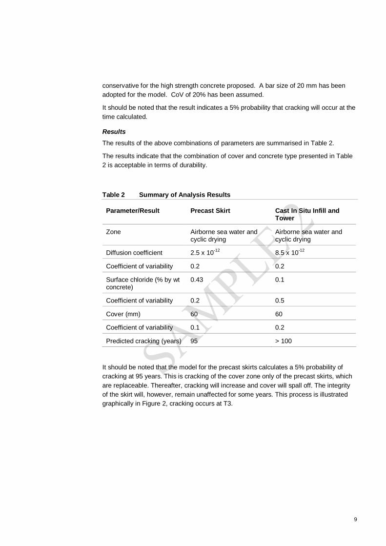
9
conservative for the high strength concrete proposed. A bar size of 20 mm has beenadopted for the model. CoV of 20% has been assumed.
It should be noted that the result indicates a 5% probability that cracking will occur at thetime calculated.
Results
The results of the above combinations of parameters are summarised in Table 2.
The results indicate that the combination of cover and concrete type presented in Table2 is acceptable in terms of durability.
Table 2 Summary of Analysis Results
Parameter/Result Precast Skirt Cast In Situ Infill andTower
Zone Airborne sea water andcyclic drying
Airborne sea water andcyclic drying
Diffusion coefficient 2.5 x 10⁻¹² 8.5 x 10⁻¹²
Coefficient of variability 0.2 0.2
Surface chloride (% by wtconcrete)
0.43 0.1
Coefficient of variability 0.2 0.5
Cover (mm) 60 60
Coefficient of variability 0.1 0.2
Predicted cracking (years) 95 > 100
It should be noted that the model for the precast skirts calculates a 5% probability ofcracking at 95 years. This is cracking of the cover zone only of the precast skirts, whichare replaceable. Thereafter, cracking will increase and cover will spall off. The integrityof the skirt will, however, remain unaffected for some years. This process is illustratedgraphically in Figure 2, cracking occurs at T3.

10
Figure 1 Graph Representing Corrosion Process
DAMAGELEVEL
INITIATION
2. rate of corrosion
1. threshold exceeded
3. first crack
4. loss of steel section
5. loss of structuralintegrity
T1T2
T3
T4
T5
PROPAGATION
PERIOD OF EXPOSURE
suggested limit states
The other components will remain unaffected for a matter of decades thereafter.
3.2.4 Site Practices
Site practices including curing and monitoring of cover pre and post placement ofconcrete will be addressed in the specification for the concrete.
3.3 Durability of Steel Piles
3.3.1 Pile Design
All piles are manufactured from 16 mm thick CHS grade 350 steel to AS 1163. Towerpiles are 1500 mm in diameter. They are filled with load bearing reinforced concrete to adepth of 3.0 to 6.0 m below the bedrock. The concrete cover between the steelreinforcement and the inside face of the steel pile is 75 mm for tower piles. The steelpiles are uncoated, and are designed as sacrificial over the concrete plug length (i.e.from the top of the piles down to approximately 4.0m below bed level).

11
3.3.2 Environment
The soffit of the pile cap is placed approximately 1m below the H.A.T. water level; hencethe steel piles pass through the following microenvironments:
below the mud line (buried zone);
within the river (submerged zone); and
intertidal zone.
The environment in the submerged and intertidal zones is estuarine river water withsalinity varying from 0 to 15,000 ppm.
Likely corrosion rates in these environments were estimated from Australian StandardAS 2159-1995.
3.3.3 Likely Deterioration Mechanisms
It is important to be clear about the nature of the corrosion risks in the specific instanceof the concrete filled steel piles. These are different in the various exposure zones ofthe piles. Where the steel liners are sacrificial, they are considered to protect thereinforced concrete from exposure until the liners are perforated due to corrosion of thesteel.
Buried Zone
Corrosion of the steel liners below the mud line is expected to be extremely slow, giventhe lack of available oxygen for reaction. Perforation of the steel is not expected tooccur within the 100 year design lifetime.
The piles are concrete filled and hence the steel liners are considered fully sacrificial.Even if perforation of the steel pile does occur, at this depth the integrity of thereinforced concrete within will not be adversely affected, due to low oxygen levelslimiting possible corrosion of the reinforcement.
The groundwater would not be expected to have a significant effect on a fly-ash modifiedconcrete.
Submerged ZoneIn the submerged zone, slightly higher corrosion rates are expected, but the steel linersin this zone are still not expected to corrode through within the 100 year design lifetime.As with the buried zone, even if the steel is perforated, oxygen starvation will result inextremely small reinforcement corrosion rates in submerged conditions, even ifreinforcement becomes active. Hence corrosion related deterioration of the concrete inthis zone can be discounted and the durability is considered satisfactory.
Intertidal Zone
It is therefore only in the intertidal zone that deterioration due to reinforcement corrosionneed be considered. The relevant mechanisms here are outlined in Table 3.

12
Table 3 Deterioration Mechanisms – Intertidal Zone
Mechanism Description Impact onStructuralAdequacy
A General corrosion leading to complete loss ofsection in steel pile; followed by
Nil
B Exposure of concrete to chloride ingressleading to corrosion activation of reinforcement;followed by
Nil
C Build-up of corrosion product sufficient to causecracking of cover concrete, and
Negligible
D Loss of section of reinforcement Potentially significant
3.3.4 Durability Assessment – Intertidal Zone
Durability Assessment Mechanism AThe scenario set out for the intertidal zone of the piles requires sufficient corrosion of thesteel pile to initiate chloride penetration of the concrete. In the GBL environment, AS2159-1995 identifies corrosion rates for design purposes ranging between 0.04 and 0.30mm/year. Although it would be expected from experience elsewhere that a rate of 0.1mm/year is most likely applicable (leading to nil perforation within 100 years), theextremely conservative corrosion rate of 0.3 mm/year has been adopted in thisassessment. This corrosion rate results in a service life of approximately 53 yearsbefore exposure of the underlying concrete.
Durability Assessment Mechanism B
The concrete would achieve significant maturation before being exposed to the water atcorrosion sites. Typically with fly ash modified concrete diffusion coefficients can betaken to reduce by a factor of 10 over 100-120 years. At 55 years, under ideal curingconditions, the diffusion coefficient will be low.
The sacrificial steel liner of the piles will still remain largely intact and so continue to limitoxygen availability.
The piles terminate at the underside of the pile cap at RL 0.0m. Reference to tide tablesfor the area of Tennyson (Long Pocket) on the Brisbane River indicates Mean HighWater Neap Tides to have to be RL 0.77m. The piles will therefore be completelyinundated twice a day even during the lowest high tides. Under these conditions theconcrete remains saturated. This is particularly the case in this design where the pileswhen exposed at low tide are shaded and protected from drying winds by the skirtelements. Although chlorides may penetrate to the steel during the design life of thestructure, the saturated concrete will not allow oxygen to reach the steel and corrosionrates will therefore remain insignificant.

13
Even once exposed to the river water, as the permanent liner perforates thereinforcement in the piles will hence not corrode.
Intertidal Zone – Durability Summary
The likely conservative time frames involved in the above mechanisms are summarisedin Table 4
Table 4 Summary of Durability of Steel Piles
Mechanism Timeframe for Piles(75 mm cover)
A Loss of steel pile section 53 years
B Reinforcement corrosion activationleading to cracking of cover concrete
> 50 years after A
3.3.5 Overall Pile Durability
In summary, provided the steel pile is considered sacrificial between the soffit of the pilecap and 6 m below the river bed, the unprotected concrete filled steel piles provideadequate durability to achieve the specified design life for the GBL of 100 years.
3.4 Durability of Pile Caps and Towers
3.4.1 General Configuration
Pile caps are to be constructed of pre cast permanent former with cast in situ infill. Theformer comes in two parts, boat shaped units that sit on top of the piles and form thebase of the in situ infill first pour of approximately 0.5 m depth and skirt units that formthe sides of the second pour and shield the piles exposed at low tide.
3.4.2 Corrosion Modeling
Constantly Saturated Concrete
As for the piles, concrete below the highest neap tide (RL 0.7m) will remain saturatedand insufficient oxygen will be present to allow significant corrosion. Elements in thisarea will therefore not be considered for diffusion modelling.
Spray and Tidal ConcreteConcrete in the environment above RL 0.7 m, is considered to be in a tidal splash zoneup to 1.4 m above mean high tide level and spray above that using both in situ andprecast concrete elements. Probabilistic diffusion modelling has shown that coversexceeding 60 mm for precast and 60 mm for in situ concrete will provide adequatedurability provision over the 100-year design life in this environment using HPC and mildsteel in the precast units and low heat or GP concrete in the in situ, pile and towerconcrete (Refer Table 2).

14
Effect of Silane CoatingIt should be noted that these predictions are based on protection from the concretealone. The specified application of silane has been ignored. It is considered likely thatthe penetration of the silanes into the high quality concrete surface of the precast panelswill be insufficient for the silane to perform as intended. Typically manufacturers in thesecircumstances require the surface of the concrete to be treated with some form ofabrasive surface preparation to open the concrete pores and allow the silane topenetrate. This defeats the object of the manufacture of concrete elements with a denselow porosity surface.
Silane application in areas that will be immersed on a regular basis will not be effective.The silane acts as a repellent rather than a barrier.
The area where the silane is likely to bring most benefit is on the top of the infill concretewhere it will be an exposed concrete finish, not off form precast.

15
3.4.3 Precast Pile Cap Boat Units
DescriptionEnvironment External Soffit Tidal wet rarely dry
External sides Protected by skirt units
Internal Protected
Proposed Concrete Mix HPC
Proposed Covers (-5/+10mm) Internal faces 45 mm
Soffit 60 mm
External side 60 mm
Top lip and rebate 60 mm
Reinforcement type Welded mesh with Class N bars
Adequacy of Cover
The general cover of 60 mm for the soffit and 60 mm for the external sides will besufficient. The units are below the lowest neap tide, will remain saturated and insufficientoxygen will be available for significant corrosion rates.
The inner faces of the pile cap shells will be exposed to salt water for a short periodduring construction, before the joints between shells can be made watertight. Providedthe concrete is water saturated, ingress of chlorides to the inner surfaces will be minimalduring this period. There is no opportunity for saline waters to penetrate to the innerface of the precast unit during service. As a consequence, the use of reduced covers to45 mm for internal surfaces is considered acceptable.
Programme RequirementsThe precast boat units will need to be installed before fully cured. In order to minimisethe amount of chlorides absorbed while the concrete is immature, the units should besaturated with fresh water before being placed and rinsed daily with fresh water whenexposed at low tide or protected from saturation with river water by a removable curingmembrane applied to the sides and inside surface (e.g. Parchem Concure A90) beforeinstallation of the skirt units.
Critical Construction Issues
The following issues must be addressed during construction:
Ensure that the precast unit can be placed over the pre driven piles and that groutseepage does not occur between the joint during placement of the in situ concrete
Ensure all concrete surfaces are saturated with potable water prior to contact withriver water and ensure that all concrete surfaces are rinsed thoroughly with potablewater daily prior to installation of the concrete skirts and Pour 1 of the infill concrete.

16
Alternatively to rinsing, all surfaces should have a removable curing membraneapplied before placing in the river
Ensure watertight fit at the joint between precast panels and piles prior to placing insitu concrete
Wash out with potable water and pump dry the inside of the panel prior to placementof in situ infill concrete
Ensure the top surfaces have been water blasted to provide a mechanical key
If crack widths greater than 0.2 mm in width develop, these are to be assessed forimpact on durability and appropriate remedial measures taken.
3.4.4 Precast Skirt Units
Description
Environment External Tidal Splash,
Internal Protected
Proposed Concrete Mix HPC
Proposed Covers(-5/+10mm) Internal faces 60 mm
External side 60 mm
Top lip and rebate 60 mm
Reinforcement type Welded mesh with Class N bars
Adequacy of CoverThe general cover of 60 mm for the external sides satisfies the requirements of thecorrosion modelling. The modelling indicates cracking at 95 years. Structural damagewill not occur for some time after cracking and not within the remaining 5 years. ReferFigure 1.
Some shrinkage between the precast skirt and the infill concrete may occur. The top ofthe skirt is above the area considered at risk from splash. However, the internal face ofthe skirt and the opposing face of the concrete infill have been considered as exposedfaces with cover of 60 mm.
The corrosion modelling is based on a Dc 28days of 2.5 x 10⁻¹². The skirts should ideallybe cast in advance to allow 56 days of curing before immersion. Testing of the proposedmix to confirm this value before casting commences is therefore not possible. It isintended that in the event that the diffusion coefficient measured is greater than thatrequired, an elastomeric barrier coating will be applied to the area of the skirts likely tobe affected by chloride induced corrosion. This is a narrow band approximately 1.5 mhigh from RL 0.7m. Testing has confirmed that above this the surface chlorides are toolow to cause corrosion. The coating will be extended up to the top of the skirts foraesthetic reasons.

17
The coating will not need to be maintained. Its function is to keep chlorides out of theconcrete for the first 5-10 years. After this time the concrete will have attained asufficiently low chloride diffusion coefficient to keep out the chlorides itself.
Critical Construction issuesThe following issues must be addressed during construction:
If crack widths greater than 0.2 mm in width develop, these are to be assessed forimpact on durability and appropriate remedial measures taken
In the event that the testing of the proposed mix indicates a higher than expecteddiffusion coefficient, apply an elastomeric coating from RL 0.7m to the top of theskirts
Ensure that exposed faces of precast units are defect free, e.g. bug-holes,honeycombing
Use concrete spacers of similar durability as the design concrete.
3.4.5 Cast Insitu Infill Concrete to Pile Cap Panels
Description
Environment Top Face Spray
Other faces Protected
Proposed Concrete Mix Low Heat
Proposed Covers (-5/+10mm) Internal faces typical 45 mm
Internal face top pile 75 mm
Top Steel and facing skirt unit 60 mm
Reinforcement type All Class N bars
Adequacy of CoverThe top surface and area facing the top of the precast skirt are the only parts of the infillconcrete to be exposed to the external environment. Cover to the main reinforcement of60 mm complies with the requirements of probabilistic modelling.
Need for Crack Control ReinforcementThe pile caps are 2.5 m deep and approximately 10 m by 20m and contain significantreinforcement. The piles will impose significant restraint on movement. Thermalmodelling will be undertaken to ensure minimised risk of cracking through measuressuch as insulation of the top of the pour to minimise temperature differential, restrictingthe maximum delivery temperature of the concrete and appropriate top surfacereinforcement to control cracking.
Critical Construction issues
The following issues must be addressed during construction:

18
Ensure that adequate bond develops between the precast and the infill concrete.This can best be achieved by ensuring that the inner surface is roughened by waterblasting
Ensure that the reinforcement is washed down to remove surface chlorides, andprotected from splash and spray prior to concrete placement
Ensure that the pour is protected from splash and spray following concrete placement
The top surface is insulated to control thermal cracking
Finished surfaces are inspected to identify any thermal cracks
If crack widths greater than 0.2 mm in width develop, these are to be assessed forimpact on durability and appropriate remedial measures taken.
3.4.6 Towers – Below RL 10 m
Description
Environment Spray
Proposed Concrete Mix DMR B2 40 MPa 80/20 GP/FA
Proposed Covers (+5/-10mm) External side 60 mm
Reinforcement type Conventional N Grade bars
Adequacy of Cover
Cover to the external faces of the towers complies with the minimum requirements asdetermined by probabilistic modelling.
Critical Construction issues
The following issues must be addressed during construction:
Ensure that reinforcement is correctly placed to achieve the required cover
Ensure that the pour is protected from splash and spray during curing.
3.4.7 Concrete in the Remaining Components
Concrete and cover in remaining components may be as follows with no cracking orspalling due to corrosion within the 100 year design life.
Element ABDCExposure
Precast/castin situ
Concrete Cover
B2 belowBridge BeamSoffit
Cast in situ DMR B2,
40 MPa
60 mmTowers, Piers 6 & 7
B1 aboveBridge BeamSoffit
Cast in situ DMR B1 40MPa
40 mm

19
Remaining pierspiles and columns
B1 Cast in situ DMR B1 40MPa
60 mm
Remaining piers allother elements
B1 Cast in situ DMR B1,
40 MPa
40 mm
Headstocks not incontact with ground
B1 Cast in situ DMR B1 40 mm
Bridge deck precastslabs
B1 Precast DMR B1,
40 MPa
40 mm
Super Tee beams B1 Precast DMR B1,
50 MPa
30 mm,20mm onupper face oftop flange
Bridge Deck infillstitch concrete
B1 Cast in situ DMR B1,
40 MPa +shrinkagereducingadmixture
40 mm
Barriers B1 Cast in situ DMR B1,
40 MPa
50 mm
Tower top pre-castpanels
B1 Precast DMR B1,
40 MPa
40 mm
Precast Kerb Units B1 Precast DMR B1,
40 MPa
30mm
This is based on the testing of the concrete from the Merivale Bridge, requirements ofthe ABDC and prediction of carbonation carried out using GHD’s in house model.
Provision has been made in the pile cap and foundations of piers 6 and 7 to facilitatefuture installation of Cathodic Protection (CP). If applied, CP would arrest corrosion ofthe reinforcement and provide the capacity to extend the life indefinitely with appropriatemaintenance.
Acid sulfate soils were only encountered between 5-9m below ground level at thelocation of Piers 3 and 4. Bored cast in situ piles will intersect these horizons. However,the disturbance to the in situ acid sulfate soil will be minimal and the soil will not dry out.No damage to the structural concrete of the pile is therefore anticipated within the 100-year design life.

20
4. Application by Design Component - Other
4.1 Deck JointsIn the busway deck areas deck joints will be either an elastomeric gland or a modularjoint type, depending on movement requirements. Industry common usage and suppliersexperience indicates that the glands are the component with the shortest life but areexpected to last at least 25 years. Three replacement cycles are expected to achieve the100-year design life.
On the pedestrian and cycle paths the joints will be sliding plate systems. Althoughhaving no components that are likely to fail, surface wear and tear may requirereplacement of the plates at the same intervals as the modular joints.
The deck joint assemblies will be designed to facilitate future replacement.
The deck joint life will be extended by keeping the joints clean of dirt and debris whichcollects between the gland surfaces. Regular cleaning will extend their life. This will beaddressed in the asset management programme.
4.2 BearingsA summary of the bearing type, location and likely life are as follows
Location Type Typicallife *
(Years)
Expectedshortest lifecomponent
Maintenance
AbutmentA, Piers1,2,3 & 4east
Elastomeric 50+ Elastomericshell
Clean andrepaint at sameintervals assteel
Pier 4 west Guided pot 40 Mechanism Ditto
Piers 5 & 8 Pot 40 Mechanism Ditto
Abutment B Guided pot 40 Mechanism Clean andrepaint at sameintervals assteel
* Typical life has been estimated based on feedback from industry suppliers and GHD’sexperience in bridge refurbishment projects.
Sketches showing typical arrangements for access, jack placing and replacement of thebearings will be provided.
Pot bearings are expected to last 40 years and 2 replacement cycles are expected toachieve the 100-year design life. Industry common usage and suppliers experience

21
indicates that the limiting life factor is the mechanism inside the bearings rather thancorrosion of the casings. The life expectancy is influenced by the amount of live rotationand shear induced back into the bearing by the movement of traffic. If the mechanismfails the only solution is to remove and replace / recondition the bearing. This is theworst-case scenario for a Pot Bearing. Current experience amongst key users of PotBearings has been that 25 years is the limit for the expected life. However, design ofcurrent pot bearings has been improved compared with bearings of 25 years ago andthey are likely to last significantly longer and at least the stated 40 years.
The use of bearings with stainless steel casing is not therefore justified as the life isdictated by the mechanism rather than corrosion.
The bearings will be inspected and maintained by grinding and spot coating the casing,where corrosion appears, at the same time as the planned coating maintenance to thestructural steel of the deck.
Industry common usage and suppliers experience indicates that elastomeric bearingsare expected to last 50+ years and 1 replacement cycle is expected to achieve the 100year design life.
4.3 Bridge Deck Steel StructureA high standard of surface preparation and coating application is easier to attain in apaint shop than on in situ steel work. For this reason a high performance coating systemhas been selected to maximise the life from that initial coating application. The paintsystem is in accordance with ISO12944-2: Global Corrosion Standard, and exceeds therequirements for high durability, >15 years, in a C3 corrosivity environment.
Within AS/NZS 2312-2002: Guide to the protection of structural steel againstatmospheric corrosion by use of protective coatings, the system would be equivalent toa PUR5 designation, satisfying the requirements for 25+ years durability until firstmaintenance within a medium corrosivity category C.
The paint system used for all painted structural steel is a 3-coat Micaceous Iron OxideEpoxy system applied to steel prepared by blast cleaning to Sa 2.5.
Binder Standard DFT microns
1 Two-component highsolids metallic zinc-richepoxy primer
AS/NZS 3750.9 Type 2
APAS 2973
75
2 Two component, highbuild micaceous ironoxide epoxy
APAS 2973 125
3 Two component, highbuild micaceous ironoxide epoxy
APAS 2973 125
Total film thickness 325 microns

22
At the bolted junctions the matching faces of the steel shall be prepared to a similar highstandard and coated with the primer only. The perimeter of the bolted areas shall besealed with joint sealant and the exposed surfaces and bolts coated with the top coatDetailing will be provided on the drawings.
In view of the likely longevity of the proposed system it is proposed that the coating bemonitored for any rust spots during the visual inspection programme that forms a keypart of the QDMR Bridge Maintenance Manual. Detailed visual inspection is carried outevery 5 years. At this time any evidence of rust spots or staining would be recorded andappropriate spot repairs carried out. As the projected life of the coating approachesand/or the quantity of spot repairs increases the frequency of inspection may need to beincreased. A decision to over coat completely would be taken on the basis of increasingsmall failures.
It is anticipated that the coating will last at least 20 years and possibly up to 30 years inthis environment with minor maintenance. Coating systems of a lesserperformance/older technology have been applied to structural steelwork on bridges overthe Brisbane River and have not had to be completely over coated in 25 years.
The coating condition will be monitored at the 15, 20 and 25 year inspections. A decisionwill be made to overcoat based on the condition of the coating. At that time all rust spotswould be ground and painted with the complete system in accordance with themanufacturer’s instructions. The remaining areas would have an additional topcoat ofthe same material applied.
It is anticipated that a full application of a new top coat would be required 3 to 4 times inthe 100 year life of the bridge.
From a durability stand point a high performance coating with a likely time to nextapplication of 25-30 years has been selected. This is more appropriate to long termdurability than a shorter life coating to be over coated at 10 years and then 10 yearintervals. The over coating at handover is therefore not recommended.
4.4 Hand RailThe hand rail will be stainless steel as specified. The support structure will be hot dipgalvanised to MRS 11.78 including AS 4690 at 600 g/m2.
The materials would be isolated electrically using appropriate insulating fittings.
Reference to various industry publications indicate that at 600 g/m2 the expected life ofthe galvanising would be 30-50 years depending on the exposure of the individualcomponents. This is well in excess of the 20 years required for replaceable componentssuch as this in accordance with Annexure 3, Part 1, Section 1.4.
These elements would also be part of the inspection programme and would be spotrepaired by grinding and application of proprietary inorganic zinc silicate coatingsystems.
As the maintenance commitment increases, likely to be around 30 years, a decisionwould need to be made to coat all the galvanised support structure. A coating system

23
would be selected at that time based on the latest technology, and is likely to last 10-30years between applications depending on coating selected and quality of application.
Alternatives would be to grit blast the galvanized components and apply flame sprayedzinc metal coating or replace with new hot dip galvanised components, both of which areconsidered unlikely to be acceptable.
4.5 Walkway CanopyThe walkway canopy structure will be in line galvanised sheet, Galvabond or similar. AS2512, Table 5.6 indicates that for an atmospheric corrosivity category most likely B,possibly C this type of coating will give a life of 25 years. The Canopy would beinspected every 5 years. Maintenance coating in the form of grinding and spot coatingwith proprietary inorganic zinc silicate coating systems will extend the life of the canopy,to 30-40 years. At this time replacement of the sheet is likely to be more economicalthan re coating.
4.6 Cable Stay SystemThe cable stay system will be the subject of a detailed submission by the selectedspecialist. Much of the detailed assessment of the durability and maintenancerequirement is dependent on the proprietary system selected. This submission to beincorporated in the Asset Management Plan will include:
design life(durability)
protection system
how the anchorages can be inspected, maintained, replaced etc
The design accommodates the sudden failure of 1 cable and the replacement of onecable at a time as specified in Annexure 3, Attachment 2, Section 2.17.5
All components will be subject to comprehensive monitoring programme, the nature ofwhich will be dependent on the selected system. Replacement of deterioratedcomponents as and when required will be carried out.

24
5. Accessibility
As part of the approach to durability the specification requires accessibility to maintain /monitor / inspect / replace all components of the bridge.
The two areas of the bridge that will require installed access are the underside of thebridge deck and the surfaces and cable anchorages of the towers. The intended accessarrangements for these are:
5.1 Piers 6 & 7From the deck level up inserts will be cast into the concrete to facilitate the fixing oftemporary towers for mast climbing work platforms or scaffolding if required in the future.
Access for visual inspection and routine maintenance including replacement of aviationlight, if required, will be from a truck mounted cherry picker.
5.2 Underside of the DeckA gantry, including a movable "work platform" arrangement will enable access to theunderside of the deck in all areas above the gantry. The gantry shall be detachable sothat, if required, it can be disconnected from the bridge and loaded onto a truck parkedon Sir William McGregor Drive beneath the deck at the UQ end of the bridge and takenaway for storage between occasions when it is needed.
Access for visual inspection and routine maintenance will be carried out at the deckbetween abutment A and pier 5 from a truck mounted cherry picker.
5.3 Deck AreasAll components on or fixed to the deck will be accessed from the deck surface A lightcherry picker or crane type access may be used if required.
5.4 Piers Beneath the DeckConcrete surfaces have no planned rehabilitation activities other than inspection andtherefore require no access. In the event that remedial activities are required scaffoldingwould be erected from the ground level or off the pile caps in the river.
Bearings at the top of some of the land piers may require replacement. This will becarried out from scaffolding erected from ground level. There are no bearings at Piers 6& 7.
5.5 Requirements by ComponentTable 9 summarises the activities and access requirements broken down by component.

25
6. Remedial Works to Extend Bridge Life to150 Years
6.1 IntroductionThe Design Life is 100 years. The Contract requests consideration of remedial worksthat may be required to extend the bridge life to 150 years and beyond.
For the period beyond 100 years, the majority of the components will continue to bemaintained and/or replaced in accordance with the asset management programme asfollows:
Structural steel deck Continue to inspect and coat at 25-30 year intervals
Bearings Continue to replace at 40-50 year intervals
Deck Joints Continue to replace at 25-30 year intervals
Canopy Replace or continue to coat as appropriate.
Hand Rails Replace or continue to coat as appropriate.
Cable Stay System Continue to inspect and replace components as required.
6.2 Concrete
6.2.1 Pile Caps below RL 0.7m
The areas below RL 0.7 are expected to remain unaffected. Saturation of the concretewill continue to stifle corrosion due to lack of oxygen.
6.2.2 Pile Caps - Skirts
In the original 100-year life design the skirt units are predicted to crack and spall atapproximately 100 years. They would have been monitored for chloride diffusion at 10yearly intervals as required by the QDMR inspection procedures. From this information itwould be possible to predict time to corrosion and cracking fairly accurately any timeafter 30 years.
Three options were available to extend the life of the skirts:
a. Application of a barrier coating. This would need to be installed beforechlorides reach the bar, likely to be 50-60 years. The barrier coating would thenneed to be maintained. Current coatings would require reapplication under theseconditions every 10-15 years. Cost of each application in 2005 dollars isapproximately $20,000 for both pile caps.
b. Application of CP. This can be delayed until appearance of first cracking whichis predicted to be at 95 years, but could be longer. Cost of CP installation forboth pile caps at 2005 dollars is approximately $350,000. Annual maintenancewould be $3-5,000 per year. A schematic drawing of a typical CP system will beprovided.

26
c. Replace Skirts. The skirts are replaceable in the event of a serious collision.
The original design intent of 100 year design life has been modified by the client toextend the life beyond 100 years by measures built in at construction time.
The revised design uses stainless steel in the outer layer of the external face of theskirts at a cover of 40 mm with plain high yield reinforcing behind at a cover of 60 mm.Modelling of chloride penetration to the “black” steel layer indicates that cracking andspalling will not occur until 100+ years.
Methods to extend this remain as for the original design.
6.2.3 Pile Caps – Top Surface
In the consortium 100-year life design, modelling of chloride penetration in this areaindicated that cracking would not take place until well over 100 years. The model did nottake into account the effectiveness of the silane application in this area and the rate ofchloride absorption/diffusion is likely to be less as a result of the silane. Maintenance ofthe silane application has been scheduled every 10 years. With this initial applicationand provided maintenance is continued, it was considered unlikely that corrosion wouldoccur within 150 years.
Chloride penetration could have been monitored through 10 yearly testing and moreaccurate prediction of the time to corrosion activation and cracking would be possibleafter 30 years. In the event that chlorides would reach the steel within the 150 year life,cathodic protection to the top steel in the pile cap could be initiated.
The original design intent of 100 year design life has been modified by the client toextend the life beyond 100 years by measures built in at construction time.
The revised design uses stainless steel in the outer layer of the top face of the pile capat a cover of 60 mm with plain high yield reinforcing behind with a cover of 100 mm.Modelling of chloride penetration to the plain high yield steel layer indicates that crackingand spalling will not occur within a time foreseeable by the model.
6.2.4 Towers – Piers 6 and 7 Below Deck
Modelling of chloride penetration in this area indicates that cracking would not take placeuntil well over 100 years.
The concrete will again be monitored for chloride penetration and more accurateprediction of the time to corrosion activation and cracking will be possible after 30 years.Application and maintenance of a silane impregnation before corrosion activation willextend the time to cracking possibly indefinitely.
Cathodic protection may be applied at any time after 100 years.
6.2.5 Remaining concrete.
The deterioration of remaining concrete will likely be due to carbonation inducedreinforcement corrosion alone. Monitoring of carbonation rates will take place. This will

27
facilitate prediction of time to corrosion initiation. Based on modelling of likelycarbonation rates, this is well beyond 100 years for all components.
Cover of 60 mm will be provided in all piers below the deck up to the soffit of theheadstocks and continue 40 mm cover in the Piers 6 and 7 to the top. With these coversand the intended concrete, carbonation is unlikely to reach the reinforcing steel until 150years and probably significantly beyond.
Cover in the deck concrete and in the pier headstocks where there is a lower risk ofchloride exposure will be 40 mm. Modelling of this indicates that carbonation will notreach the steel within 100 years. The model does not, however, take account of theimproved compaction and surface finish likely in pre-cast segments. It could be that therate of carbonation will be significantly lower with extension of this time to beyond 150years. This will be monitored as part of the QDMR inspection programme and in theevent that it becomes an issue within the 150 year life an anti-carbonation coating canbe applied to the soffit and sides and some form of topping to the upper surfaces. Thesewould arrest carbonation. The coatings would need to be maintained and could be re-applied at the time of recoating the steel and/or resurfacing the deck.

28
Table 5 Contract References to Durability (Maintenance RequirementsConsidered in Separate Report)
Section Subsection Component Requirement
Annexure 3
Part 1
Section 1.4 General Bridge design life 100 years,pavements 20 years
Annexure 3
Attachment 2
Section 1.2 General Materials to deliver lowestwhole of life cycle cost
Ditto Ditto CorrosionProtection System
To provide details of coating,methods and frequency ofcoating, maintenance &susceptibility to vandalism
Ditto Ditto General Accessibility to maintain /monitor / inspect / replace
Ditto Ditto General Material Selection to meet thedesign life
Ditto Ditto General Member selection andconnection details to facilitatelongevity, inspection, testingand maintenance
Ditto Ditto General Shut down and disruption totraffic on and under the bridge
Ditto Ditto General Remedial works required toextend bridge life to 150 yearsand beyond
Annexure 3
Attachment 2
Section2.17.5
Amendments toABDC - Cable Stay
Ability to withstand failure of 1cable and to replace 1 cable ata time.
Annexure 3
Attachment 2
Section 4.2 Amendments toABDC - Bearings
Steel in bearings to be carbonsteel. Elastomeric bearings toAS 1523. Bearings to beaccessible for maintenance anddesigned to minimize ingress ofdirt, moisture etc.
Annexure 3
Attachment 2
Section 4.3 Amendments toABDC – DeckJoints
Joint cover plates for thepedestrian walkway, cycle pathand joints in kerbs and barriersshall be stainless steel. Refer toBCC’s S600 Stainless SteelSpecification.
Annexure 3
Attachment 2
Section 5.2 Amendments toABDC –Reinforcing steel
Reinforcing in tidal and splashzones to be carbon steel.
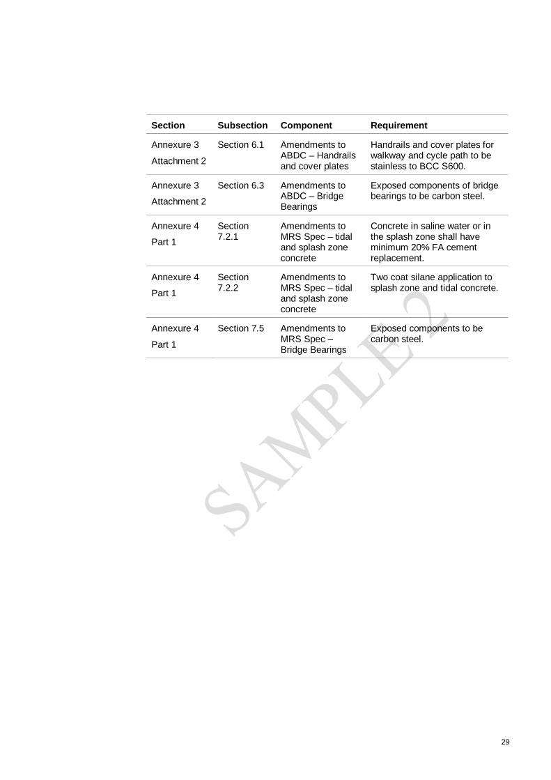
29
Section Subsection Component Requirement
Annexure 3
Attachment 2
Section 6.1 Amendments toABDC – Handrailsand cover plates
Handrails and cover plates forwalkway and cycle path to bestainless to BCC S600.
Annexure 3
Attachment 2
Section 6.3 Amendments toABDC – BridgeBearings
Exposed components of bridgebearings to be carbon steel.
Annexure 4
Part 1
Section7.2.1
Amendments toMRS Spec – tidaland splash zoneconcrete
Concrete in saline water or inthe splash zone shall haveminimum 20% FA cementreplacement.
Annexure 4
Part 1
Section7.2.2
Amendments toMRS Spec – tidaland splash zoneconcrete
Two coat silane application tosplash zone and tidal concrete.
Annexure 4
Part 1
Section 7.5 Amendments toMRS Spec –Bridge Bearings
Exposed components to becarbon steel.
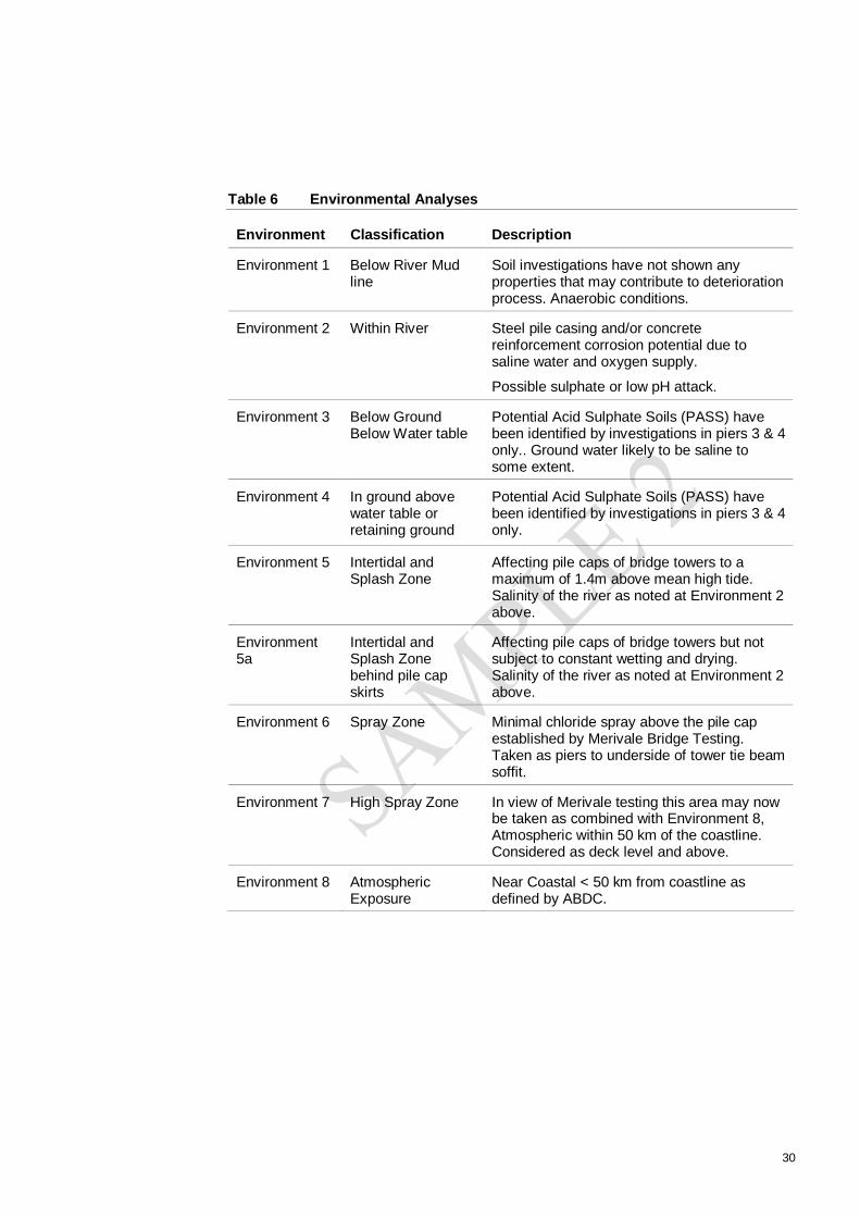
30
Table 6 Environmental Analyses
Environment Classification Description
Environment 1 Below River Mudline
Soil investigations have not shown anyproperties that may contribute to deteriorationprocess. Anaerobic conditions.
Environment 2 Within River Steel pile casing and/or concretereinforcement corrosion potential due tosaline water and oxygen supply.
Possible sulphate or low pH attack.
Environment 3 Below GroundBelow Water table
Potential Acid Sulphate Soils (PASS) havebeen identified by investigations in piers 3 & 4only.. Ground water likely to be saline tosome extent.
Environment 4 In ground abovewater table orretaining ground
Potential Acid Sulphate Soils (PASS) havebeen identified by investigations in piers 3 & 4only.
Environment 5 Intertidal andSplash Zone
Affecting pile caps of bridge towers to amaximum of 1.4m above mean high tide.Salinity of the river as noted at Environment 2above.
Environment5a
Intertidal andSplash Zonebehind pile capskirts
Affecting pile caps of bridge towers but notsubject to constant wetting and drying.Salinity of the river as noted at Environment 2above.
Environment 6 Spray Zone Minimal chloride spray above the pile capestablished by Merivale Bridge Testing.Taken as piers to underside of tower tie beamsoffit.
Environment 7 High Spray Zone In view of Merivale testing this area may nowbe taken as combined with Environment 8,Atmospheric within 50 km of the coastline.Considered as deck level and above.
Environment 8 AtmosphericExposure
Near Coastal < 50 km from coastline asdefined by ABDC.

31
Table 7 Deterioration Mechanisms
Potential Mode ofFailure
DeteriorationMechanism
Factors Controlling Rate ofDeterioration
ReinforcementCorrosion inducedcracking, delaminationand spalling ofreinforced concrete
Chloride induced
Carbonation induced
Macrocell corrosion
Localised corrosion atcracks and joints
Environmental characteristics
Concrete quality
Crack control
Reinforcement cover
As placed concrete quality
Joint preparation
Concrete Degradation Alkali-aggregatereactivity
Sulphate attack
Acid attack fromcontaminatedgroundwater and soil
Environmental characteristics
Aggregate properties
Crack control
Binder type
Concrete quality
Surface preparation
Exposed Steel andOther Metal
Corrosion
Coating/protectionfailure
Dissimilar metals
Detailing
Electrical insulation
Coating maintenance
Movement Joints Excessive movementleading to poor runningsurface
Concrete cracking,delamination andspalling
Wear
Capacity for replacement
Design detail
Workmanship
Prevention of water penetration
Reinforcement detailing
Traffic load and volume
Bridge Bearings Construction loading
Environmentaldegradation
Wear
Capacity for replacement
Positioning
Protection
Design
Traffic load and volume
Ground Movement Deflection & settlement
Poor running surface
Joint failure - Cracking
Foundation design
Environmental characteristics

32
Table 8 Durability Issues by Design Element
DesignElement
DesignLife(Years)
Zone Issues Which May Affect DurabilityDesign Approach to the Durability Issues
Cast in situbored piles– River Bed
100 Below Mud lineand within river.
Chloride induced corrosion of reinforcementonly above water level.
Sulphate or low pH attack.
Sacrificial permanent 16 mm steel casing
ABDC B2 40 MPa concrete with 20% FAreplacment
70 mm cover
Electrical continuity of reinforcement tofacilitate impressed current CathodicProtection to extend life if required.
Cast in situbored piles– FloodPlain
100 Below GroundAbove andBelow WaterTable
Chloride contamination from ground water onlyabove water level.
Pile buried, inundation events infrequent,oxygen minimal. ABDC Class B2 adequatewith 20 % FA cement replacement.
Abutments
RetainingWalls
100 AtmosphericExposed &
Below GroundAbove WaterTable
Atmospheric pollutants
Requirement for concrete curing.
Early age thermal induced cracking in retainingwalls
Design as ABDC exposure classification B2and include 20 % FA replacement.
Curing membrane applied immediatelyfollowing removal of formwork.
Review casting sequence for thermal issues.
Driven pre-castconcretepiles –Flood Plain
100 Below GroundAbove andBelow WaterTable
Chloride contamination from ground water onlyabove water level.
Pile buried, inundation events infrequent,oxygen minimal. Precast concrete to ABDCClass B2 adequate.

33
DesignElement
DesignLife(Years)
Zone Issues Which May Affect DurabilityDesign Approach to the Durability Issues
Pile Caps –River
100 Intertidal andsplash zone.
Chloride induced corrosion of reinforcement
Large mass of concrete, heavy reinforcementand deep section may lead to placementrelated difficulties.
Early age thermal induced cracking.
Requirement for concrete curing.
Permanent precast concrete panel formworkwith FA cement replacement to 30%, SilicaFume to 8% and cover of 60 mm..
Infill concrete to be up to 40% FA replacementwith appropriate mix design and monitoring toreduce temperature rise.
Top surfaces to have 60 mm in situ cover.
Curing membrane to be applied to all surfacesexcept top of pile cap, latter to be wet cured..
Silane application to top of pile cap only.
Stainless steel top layer of reinforcing in top ofpile cap.
Electrical continuity of reinforcement tofacilitate impressed current CathodicProtection to extend life if required.
Pile Caps –Flood Plain
100 Below GroundAbove andBelow WaterTable
Chloride contamination from ground waterand/or flooding.
Pile cap buried, inundation events infrequent,oxygen minimal. ABDC Class B2 adequatewith 20 % FA cement replacement.
Piers 6 &7,– (river toundersideof tie beamsoffit)
100 Spray Zone Chloride induced corrosion of reinforcement
Large mass of concrete, restrained by pile capat the base.
Early age thermal induced cracking.
Requirement to strip and raise formwork within24 hours
Requirement for concrete curing.
Testing at Merivale Bridge indicated minimalchlorides.
ABDC Class B2 adequate with 20 % FAcement replacement, 60 mm cover
Curing membrane applied immediatelyfollowing removal of formwork.
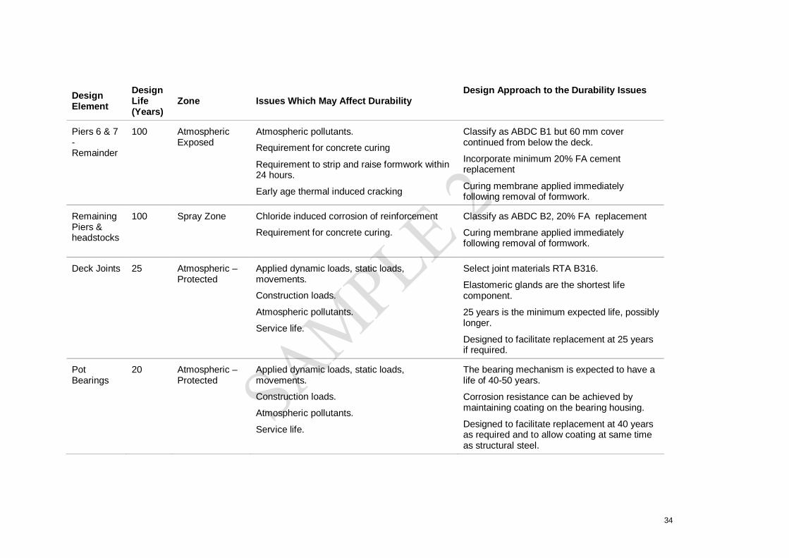
34
DesignElement
DesignLife(Years)
Zone Issues Which May Affect DurabilityDesign Approach to the Durability Issues
Piers 6 & 7-Remainder
100 AtmosphericExposed
Atmospheric pollutants.
Requirement for concrete curing
Requirement to strip and raise formwork within24 hours.
Early age thermal induced cracking
Classify as ABDC B1 but 60 mm covercontinued from below the deck.
Incorporate minimum 20% FA cementreplacement
Curing membrane applied immediatelyfollowing removal of formwork.
RemainingPiers &headstocks
100 Spray Zone Chloride induced corrosion of reinforcement
Requirement for concrete curing.
Classify as ABDC B2, 20% FA replacement
Curing membrane applied immediatelyfollowing removal of formwork.
Deck Joints 25 Atmospheric –Protected
Applied dynamic loads, static loads,movements.
Construction loads.
Atmospheric pollutants.
Service life.
Select joint materials RTA B316.
Elastomeric glands are the shortest lifecomponent.
25 years is the minimum expected life, possiblylonger.
Designed to facilitate replacement at 25 yearsif required.
PotBearings
20 Atmospheric –Protected
Applied dynamic loads, static loads,movements.
Construction loads.
Atmospheric pollutants.
Service life.
The bearing mechanism is expected to have alife of 40-50 years.
Corrosion resistance can be achieved bymaintaining coating on the bearing housing.
Designed to facilitate replacement at 40 yearsas required and to allow coating at same timeas structural steel.

35
DesignElement
DesignLife(Years)
Zone Issues Which May Affect DurabilityDesign Approach to the Durability Issues
ElastomericBearings
20 Atmospheric –Protected
Applied dynamic loads, static loads,movements.
Construction loads.
Atmospheric pollutants.
Service life.
The bearing is expected to have a life of 40-50years.
Designed to facilitate replacement at 40 yearsas required.
BridgeSteel DeckStructure
100 AtmosphericExposed
Atmospheric Pollutants
Deterioration of Applied Coatings
Corrosion
Dissimilar metals
Shop based coating of components will beundertaken with required surface preparationunder controlled conditions.
A quality coating system will be applied undercontrolled conditions to maximise interval tomaintenance.
Make provision for access to grind corrosionspots and reapply top-coat at 20 year orgreater intervals based on coatingperformance.
All members to be “open” to allow inspectionand maintenance.
BridgePrecastDeck
100 AtmosphericExposed
Potential for DEF and AAR.
Early age thermal induced cracking.
Shrinkage at stitch joints leading to open joint
Atmospheric pollutants.
Rainfall and drainage.
Applied dynamic loads.
Construction loads.
Curing
Maximise curing time before placement of unitsand incorporate shrinkage reducing admixturein stitch joints
Design as ABDC exposure classification B1and include 20 % FA replacement.
Consider temporary case loading for handling.
Prepare handling procedures to minimisedamage.
Ensure drainage is designed and managed tominimise standing water.

36
DesignElement
DesignLife(Years)
Zone Issues Which May Affect DurabilityDesign Approach to the Durability Issues
Hand Rail 20 AtmosphericExposed
Atmospheric pollutants.
Galvanising.
S/S handrail.
Hand rails themselves stainless steel
Stainless steel components will be electricallyinsulated with appropriate washers.
Support structure galvanised at 600g/m2 withan estimated life of 30 years.
Make provision for access to paint after 30years
Cable StaySystem
NB: genericrequirements only. Tobeconfirmedonappointment ofspecialistcontractor
100 AtmosphericExposed
Atmospheric Pollutants
Deterioration of Applied Coatings
Corrosion
Dissimilar metals
Cable system will be the subject of a detaileddurability submission by BBR. All componentswill be subject to comprehensive monitoringand maintenance in accordance with BBRnominated procedures; see maintenanceprogramme. Replacement of deterioratedcomponents as and when required will becarried out.
WalkwayCanopy
30 AtmosphericExposed
Atmospheric Pollutants
Deterioration of Applied galvanising
Corrosion
Dissimilar metals
Inspect at 5-year intervals and touch up.
Planned replacement at 30 years from deckand gantry.
In line galvanised sheet 42 micron thicknessAS 2312 indicates exposure category B/Cborder with projected life in the region of 25years. With maintenance coating this willextend to 30 years. Replace or paint at thistime.

37
DesignElement
DesignLife(Years)
Zone Issues Which May Affect DurabilityDesign Approach to the Durability Issues
ConcreteBarriers
100 AtmosphericExposed
Early age thermal induced cracking.
Shrinkage cracking
Atmospheric pollutants.
Rainfall and drainage.
Curing
Incorporate movement joints at appropriateintervals
Inspect and renew joint sealant at expansionjoints as required, projected life 20-30 yearsdepending on exposure location.
Design as ABDC exposure classification B1and include 20 % FA replacement.
Curing membrane applied immediatelyfollowing removal of formwork.
Drainage 100 AtmosphericExposed
Atmospheric Pollutants
Deterioration of Applied galvanising on grateand frame and pipe hangers
Corrosion
Dissimilar metals
UV degradation of PVC/GRP pipe
Hanger galvanising beneath bridge has anestimated life of 30 years. Make provision foraccess to paint or progressively replace after30 years.
Galvanising in grate and frame will havereduced life with build up of debris holdingmoisture. Clean monthly as part ofmaintenance programme. Inspect andmaintenance coat with zinc rich coating asrequired.
PVC/GRP in shaded environment likely toreach 100 years. Inspect and replace/maintainas necessary.

38
DesignElement
DesignLife(Years)
Zone Issues Which May Affect DurabilityDesign Approach to the Durability Issues
PrecastGirders.
100 AtmosphericExposed
Potential for DEF and AAR.
Early age thermal induced cracking.
Atmospheric pollutants.
Applied dynamic loads.
Construction loads.
Curing
Maximise curing time before placement of units
Design as ABDC exposure classification B1and include 20 % FA replacement.
Consider temporary case loading for handling.
Prepare handling procedures to minimisedamage.
Tower tip –steel frame
100 Sheltered Moisture penetration at joints Support structure galvanised with an estimatedlife in excess of 30 years in sheltered dryenvironment.
Joints designed with weather seal.
Maintain seal, life 20-30 years depending onexposure.
Drainage provision to allow any water toescape.
Inspect and maintain galvanising beyond 30yrs if required.
Tower tip –precastpanels
100 AtmosphericExposed
Potential for DEF and AAR.
Early age thermal induced cracking.
Atmospheric pollutants.
Rainfall and drainage.
Applied dynamic loads.
Construction loads.
Curing
Thermal cracking
Maximise curing time before placement of unitsand incorporate shrinkage reducing admixturein stitch joints
Design as ABDC exposure classification B1and include 20 % FA replacement.
Consider temporary case loading for handling.
Prepare handling procedures to minimisedamage.
Design fixing system to accommodate thermalmovement.

39
Table 9 Access Arrangements
MainComponent
SubComponent
Activity Access
Pier Pile cap QDMR Level 1 –
Visual inspection
Boat/foot
QDMR Level 2 –
Visual inspection plus photos towithin 3 m or telephoto equivalent
Boat/foot plus telephoto
QDMR under water Boat/diver/under watercamera
QDMR Level 3 –
Chloride and Carbonation samplingand testing, selected locations
Delamination survey, selectedlocation
Boat/foot plus telephoto
Pier & Towerconcretebeneath deck
QDMR Level 1 –
Visual inspection
Boat/foot and shore based
QDMR Level 2 –
Visual inspection plus photos towithin 3 m or telephoto equivalent
Boat/foot and shore basedwith binoculars
QDMR Level 3 –
Chloride and Carbonation samplingand testing, selected locations
Delamination survey, selectedlocation
Boat/foot
Carbonation testing atbase and above deckrepresentative ofremainder.
Tower concreteabove deckincludingprecast tops &Cableanchorages
QDMR Level 1 –
Visual inspection
Deck based
QDMR Level 2 –
Visual inspection plus photos towithin 3 m or telephoto equivalent
Deck based with telephoto
Plus check covered cableanchorages from cherrypicker or mast climbingwork platform

40
MainComponent
SubComponent
Activity Access
QDMR Level 3 –
Chloride and Carbonation samplingand testing, selected locations
Delamination survey, selectedlocation
Cherry Picker or mastclimbing work platform.
Cable System
NB Activities tobe confirmed byspecialistcontractor
Load check Cherry picker or mastclimbing work platform ordeck depending on finaldesign
Cable System Visual inspection for corrosion,deflection, cracking, leakage ofwax, impact or vandalism damage.
Progressive inspection,.Replacement of deterioratedcomponents.
Cherry picker, mastclimbing work platform orscaffold at top, from bridgedeck at bottom.
Measure tension on 4-8 cables asrequired
Cherry picker, mastclimbing work platform orscaffold at top, from bridgedeck at bottom.
Steel supportframe of towertop
QDMR level 3 – Close visualinspection plus testing ofconnections
Cherry picker, mastclimbing work platform orscaffold at top, from bridgedeck at bottom to accesshatch.
Underside ofdeck
Steel structure QDMR Level 1 –
Visual inspection
Boat/foot and shore based
QDMR Level 2 –
Visual inspection plus photos towithin 3 m or telephoto equivalent
Spot coating repairs if any arising
Boat/foot and shore basedwith telephoto.
QDMR Level 3 –
Close visual inspection plus testingof connections
Gantry
Grind rust spots, patch prime andtop coat
Monitor at QDMR 2 inspection
Gantry

41
MainComponent
SubComponent
Activity Access
Concrete decksoffit
QDMR Level 1 –
Visual inspection
Boat/foot and shore based
QDMR Level 2 –
Visual inspection plus photos towithin 3 m or telephoto equivalent
Boat/foot and shore basedwith telephoto.
QDMR Level 3 –
Close visual inspection plus testingfor carbonation/chlorides
Gantry
Services Visual inspection for leakage Boat/foot and shore basedwith binoculars
Close up inspection Gantry
Replacement Scaffolding/Gantry
Bearings andjoints
QDMR Level 1 –
Visual inspection
Ground level/cherry picker
QDMR Level 2 –
Visual inspection plus photos towithin 3 m or telephoto equivalent
Gantry
QDMR Level 3 – Gantry
Replacement of joints Scaffolding from groundlevel
Coating of bearings Scaffolding from groundlevel
Replacement of bearings Scaffolding from groundlevel
NB QDMR Level 2 Inspection interval extended to 5 years to align with other inspection andmaintenance activities.

Appendix A
Durability Design Summary Tables

Duration (years)
Contract Reference
Potential Mode of Failure Deterioration Mechanism Factors Controlling Rate ofDeterioration
End of Life Criteria (Expected governing failure mechanism)
Chloride induced
Carbonation induced
Macrocell corrosion
Localised corrosion at cracksand jointsChloride induced
Carbonation induced
Cracking due to heat of hydrationLocalised corrosion at cracksand joints
Sulfate attack of concrete. Sulfate attack of concrete Mobility of ground water
Weakening and erosion of concrete from acid sulfate soils.
Degradation of concrete and steel from acid
Degree of oxidation of PASS and extent of ASS.
Sulfate attack of concrete. Sulfate attack of concrete Mobility of ground water
Weakening and erosion of concrete from acid sulfate soils.
Degradation of concrete and steel from acid
Degree of oxidation of PASS and extent of ASS.
Reinforcement Corrosion induced cracking, delamination and spalling of concrete
Chloride induced Environmental characteristcis, concrete mix, crack control, reinforcment cover, as placed concrete quality
Softening of the concrete surface due to sulfate attack
Pile caps 100 years Project Specification requires 100 year design life
Reinforcement Corrosioninduced cracking,delamination and spalling ofreinforced concrete
Environmental characteristicsConcrete mixCrack controlReinforcement coverAs placed concrete qualityJoint preparation
chloirde induced reinforcement corrosion - first crack
Pile caps in river - In situ in fill concrete
100 years Project Specification requires 100 year design life
Piles in river 100 years Project Specification requires 100 year design life
Softening of the concrete surface due to sulfate attack
Table 1: Structure Durability Outline
Critical Durability Components
Service Life
Environmental characteristicsConcrete mixCrack controlReinforcement coverAs placed concrete qualityJoint preparation
chloirde induced reinforcement corrosion - first crack
Pile caps in river - Pre cast units
100 years Project Specification requires 100 year design life
Reinforcement Corrosioninduced cracking,delamination and spalling ofreinforced concrete
1 Table 1

Duration (years)
Contract Reference
Potential Mode of Failure Deterioration Mechanism Factors Controlling Rate ofDeterioration
End of Life Criteria (Expected governing failure mechanism)
Critical Durability Components
Service Life
Sulfate attack of concrete. Sulfate attack of concrete Mobility of ground water
Weakening and erosion of concrete from acid sulfate soils.
Degradation of concrete and steel from acid
Degree of oxidation of PASS and extent of ASS.
Chloride induced
Carbonation induced
Cracking due to heat of hydration
Localised corrosion at cracksand joints
Chloride induced
Carbonation induced
Cracking due to heat of hydration
Localised corrosion at cracksand joints
Steel Deck Girders 100 years Project Specification requires 100 year design life
General atmospheric corrosion leading to loss of section.
Atmospheric corrosion Environmental Characteristics Corrosion leading to a loss of section greater than 10%
Piles 100 years Project Specification requires 100 year design life
Softening of the concrete surface due to sulfate attack
Environmental characteristicsConcrete mixCrack controlReinforcement coverAs placed concrete qualityJoint preparation
chloirde induced reinforcement corrosion - first crack
Reinforcment corrosion induced cracking and spalling of reinforced concrete
Main Piers in River 100 years Project Specification requires 100 year design life
Reinforcment corrosion induced cracking and spalling of reinforced concrete
Environmental characteristicsConcrete mixCrack controlReinforcement coverAs placed concrete qualityJoint preparation
carbonation induced reinforcement corrosion - first crack
Other piers Project Specification requires 100 year design life
100 years
2 Table 1

Duration (years)
Contract Reference
Potential Mode of Failure Deterioration Mechanism Factors Controlling Rate ofDeterioration
End of Life Criteria (Expected governing failure mechanism)
Critical Durability Components
Service Life
Chloride induced
Carbonation induced
Localised corrosion at cracks and joints
Potential for DEF
Tower Tip Steel Frame 100 years Project Specification requires 100 year design life
General atmospheric corrosion leading to loss of section.
Atmospheric corrosion Environmental Characteristics Corrosion leading to a loss of section greater than 10%
Atmospheric Corrosion
Deterioration of Applied Coatings
Dissimilar metals
Elastomeric Bearings 20 years Project Specification requires 100 year design life
Cracking and/or bulging of bearing. Hardening of elastomer.
Oxidation and exposure to UV light.
Environmental characterisitics and composition of elastomer
Excessive bulging and/or cracking or splitting
Applied dynamic loads, static loads, movements.
Mecahnism life
Construction loads. Design
Corrosion Environamnatl characteristics, coating
Oxidation and cracking of elastomerPuncture of elastomer
Hand Rails 20 years Project Specification requires 100 year design life
General atmospheric corrosion leading to loss of section.
Atmospheric corrosion Environmental Characteristics Corroded appearnace, sharp havard to pedestrians
Cable Stay System 100 years Project Specification requires 100 year design life
Corrosion leading to loss of section
Environmental Characteristics Corrosion leading to a loss of section greater than 10%
Expansion Joints 20 years Project Specification requires 100 year
Loss of water tightness
Precast Concrete Deck, T Roffs and Pre cast Tower
Units
100 years Project Specification requires 100 year design life
Reinforcement Corrosion induced cracking, delamination and spalling of concrete
Pot Bearings 20 years Project Specification requires 100 year design life
Mechanical wear Loss of movment capabiltiy
Environmental characterisitics, Concrete mix, Crack control, reinforcement cover, joint preparation, quality of concrete placement.
Carbonation induced reinforcement corrosion
Environmental characterisitics and composition of elastomer
Puncture of elastomer
3 Table 1

Duration (years)
Contract Reference
Potential Mode of Failure Deterioration Mechanism Factors Controlling Rate ofDeterioration
End of Life Criteria (Expected governing failure mechanism)
Critical Durability Components
Service Life
Walkway Canopy 30 Years Project Specification requires 100 year design life
General atmospheric corrosion leading to unacceptable appearance loss of section.
Atmospheric corrosion Environmental Characteristics Corroded appearnace
Chloride induced
Carbonation inducedLocalised corrosion at cracks and joints
Corrosion of hanging system Atmospheric corrosion Environmental Characteristics Corrosion leading to a loss of section greater than 10%
Corrosion of gratings and surrounds
Atmospheric corrosion/standing water
Environmental Characteristics Corrosion leading to a loss of section greater than 10%
UV embrittlement of PVC pipes UV exposure Environmental Characterisitcs Cracking of pipe
Table Legend
Table 1 Table 2 Table 3 Table 4 Table 5 Table 6 Table 7 Table 8
Environmental characterisitics, Concrete mix, Crack control, reinforcement cover, joint preparation, quality of concrete placement.
Carbonation induced reinforcement corrosion
Reinforcement Corrosion induced cracking, delamination and spalling of concrete
Project Specification requires 100 year design life
100 yearsConcrete Barriers
Drainage System 100 years Project Specification requires 100 year design life
4 Table 1

No. ZoneSulphate Concentration 250mg/l concrete piles Sulphate attack of concrete 50 MPa concrete Cement content, water cement ratio and
quantity of cement replacement inadequate to achieve 100 year life.
Concrete mix designed in accordance with BRE special digest 1.
pH 6.5Salinity of the river at this point has been based on BCC monitoring at Indooroopilly 10 year average of 10 ppt. Salinity at site has been taken as 10-15 ppt. Possible sulphate or low pH attack.
concrete piles, permananent steel casing used for constructuion. Remainds in palxce as sacrificial steel
Steel pile casing and/or concrete reinforcement corrosion potential due to saline water and oxygen supply.
50 MPa concrete No. steel casing estimated minimum time to perforation ~ 50 years
pile caps as aboveFully submerged below water table. Oxygen restricted. Benign conditions in relation to chloride and sulphate concentrations in the soil.
concrete piles No Potential Acid Sulphate Soils (PASS) have been identified by investigations to date but would require confirmation. Ground water likely to be saline to some extent.
50 MPa concrete yes none required.
Pile capBenign conditions in relation of sulphate and chlorides in the soil. Periodic wettign and drying from groundwater movements / rainwater.
concrete piles No Potential Acid Sulphate Soils (PASS) have been identified by investigations to date but would require confirmation, notably on the West Bank flood plain.
50MPa concrete code requirements adequate none required.
Pile cap as aboveChloride Concentration 1000mg/l Pre cast skirt and "boat" units of the pile
capChloride Induced corrosion AS5100.5 - 50MPa
concrete, minimum cover 50mm
No. Blended mix, 20% FA, 8% Silica fume. Maximum water binder ratio of 0.35 cover 70 mm
Sulphate Concentration 250mg/l steel cased concrete piles as above no. steel casing estimated minimum time to perforation ~ 50 years
Chloride Concentration 1000mg/l Pre cast skirt and "boat" units of the pile cap
Affecting pile caps of bridge towers but not subject to constant wetting and drying. Salinity of the river as noted at Environment 2 above.
as above no. Options include: Silane coating; cathodic protection; demountable units.
Sulphate Concentration 250mg/l steel cased concrete piles Steel casing will prevent deterioration of the concrete
not specified
Chloride Concentration 1000mg/l in river water. Potential for higher concentrations due to wetting and drying effects.
Pile caps in situ concreteMinimal chloride spray above the pile cap established by Merivale Bridge Testing.
40 Mpa No. Large concrete pours for both, full thermal crack assesment to be carried out
Sulphate Concentration 250mg/l In river piers 2m above pile cap Sulphate attack of concrete none specified Concrete mix designed in accordance with BRE special digest 1.
4
Identified Additional Requirements
3 Below Water table
2 Within River below water
level
Below River Mud Line
1
Environment Potential Deterioration Mechanisms
Assess if Code Sufficient Code Requirements Affected Structural ComponentsEnvironmental Details
Table 2: Component Exposure Assessment (All Components)
In ground above water
table or retaining ground
Intertidal and Splash Zone
Intertidal and Splash Zone behind pile cap skirts
Spray Zone
5
5a
6
5 Table 2

No. ZoneIdentified Additional
RequirementsEnvironment Potential Deterioration
MechanismsAssess if Code Sufficient Code Requirements Affected Structural ComponentsEnvironmental Details
Atmospheric exposure conditions similar to near coastal <50km from coastline as defined by ABDC.
Pier concrtete >2m above pile cap In view of Merivale testing this area may now be taken as combined with Environment 8, Atmospheric within 50 km of the coastline. Considered as deck level and above.
40 MPa
Other piers Carbonation induced reinforcement corrosion
none specified No. Cement content, water cement ratio and quantity of cement replacement inadequate to achieve 100 year life.
Steel deck girders General atmospheric corrosion none specified No. high quality coating applied in the workshop prior to installtion on site.
Concrete Deck Carbonation induced reinforcement corrosion
none specified No. Cement content, water cement ratio and quantity of cement replacement inadequate to achieve 100 year life.
Parapets Carbonation induced reinforcement corrosion
as above as above as above
Handrails General atmospheric corrosion none specified Stainless steel handrails
Pot Bearings General atmospheric corrosion of metallic parts
none specified Provision to be made to allow replacement.
Table 1 Table 2 Table 3 Table 4 Table 5 Table 6 Table 7 Table 8
7 High Spray Zone
Atmospheric Exposure
8 Near Coastal < 50 km from coastline as defined by ABDC.
Table Legend
6 Table 2

No. Zone 2 Within river
below water level.
Cast in situ bored piles Chloride induced corrosion of reinforcement only above water level.
Sacrificial permanent 16 mm steel casing
QC measurement of casing thickness.
1 Below River mud line
Cast in situ bored piles Sulphate or low pH attack. 40 MPa, Max w/c 0.4. Minimum 30% FA and 8% SF. Minimim 400kg/m3 cementitous content.
High workability mix suitable for placement by tremie tube.
Concrete mix dockets and cylinder results.
5 Intertidal andsplash zone.
Pile cap pre cast skirts and boat units
Chloride induced corrosion of reinforcement.
Concrete to be 20% FA 8% silica replacement with appropriate mix design.Elastomeric barrier coating to the outer surfaces of the skirt units if diffusion results arehigher than expected.
Appropriate curing before immersion Mix dockets, cover meter and visual inspection
5 Intertidal andsplash zone.
Pile caps Chloride induced corrosion of reinforcement.
Concrete to be 40% FA replacement with appropriate mix design andmonitoring to reduce temperature rise.Top surfaces to have 60 mm in situ cover.Curing membrane to be applied.Silane application only to the top surfaceElectrical continuity of reinforcement to facilitate impressed current CathodicProtection to extend life if required.
Large mass of concrete, heavy reinforcement and deep section may lead to placement related difficulties.Risk of early age thermal induced cracking.Requirement for concrete curing. Engineer's approval required for early age thermal modelling of contractors proposed pour sequence and methodology. Hot weather concreting measures in specification. Self compacting concrete in deep sections to avoid need to man access for placement and compaction. Specification requirements for frequency of electrical continuity testing and resistivity criteria.
Electrical continuity testing during concrete placement. Thermo couples installed in pour to confirm modelling. Visual inspection of pile cap 48 hours after casting.
6 Spray Zone Main in river piers Chloride induced corrosion of reinforcement.
Testing at adjacent bridge indicates minimal chlorides in this area, considered Class B2
8 Atmospheric exposure
Steel Deck Girders Atmospheric corrosion Maximise surface prpararation, shop blasting to Sa 2.5. Application of maximum quality/thickness coating system to maximise time to first maintenance.
Nominate surface preap and coating system
Engage NACE coating inspector to confirm surface preparation, dft and no "holidays" before erecton.
Validation Measure/Test
Table 3: Durability Provisions for Critical Components - Design Phase
Environment Classification
Construction Contract ProvisionDesign Mitigation MeasureIdentified Deterioration MechanismsAffected Structural Components
7 Table 3

No. Zone
Validation Measure/TestEnvironment Classification
Construction Contract ProvisionDesign Mitigation MeasureIdentified Deterioration MechanismsAffected Structural Components
8 Atmospheric exposure
Cable stay system Atmospheric corrosion Require specialist supplier to provide details of inspection procedure at ends and along cable length combined with capability to remove and repalce one cable at a time without affecting the bridge
Nominate procedure Demonstrate procedure and cable replacement as part of the contract
Table 1 Table 2 Table 3 Table 4 Table 5 Table 6 Table 7 Table 8
Table Legend
8 Table 3

Affected Structural Component
Environment No.
Zone Activity Frequency Access Provision
Intervention Level
Activity Frequency Access Provision
Steel Bearings 8 Atmospheric Exposure Cleaning bearings 2 years Cherry picker from road adjacent
Rust staining on bearings
Recoat bearings 10 years Cherry picker from road adjacent
Wash girders, 2 years Gantry provided by contractor and stored at client yard
Greater than 10% of the surface area affected by bubbling, peeling or rust staining or already spot coated
patch painting 5 years GantryExpansion joints 8 Atmospheric Exposure clean joints 1 year Deck
Cable stays 8 Atmospheric Exposure Load check 3 years Mast climbing work platform and
deck
Hand rail stanchion
8
Atmospheric Exposure
Wash 2 years Deck Greater than 10% of the surface area affected by bubbling, peeling or rust staining.
Recoat 30 years Deck
Canopy
8
Atmospheric Exposure
Wash 2 years Deck Greater than 10% of the surface area affected by bubbling, peeling or rust staining.
Recoat 30 years Deck
Table Legend
Table 1 Table 2 Table 3 Table 4 Table 5 Table 6 Table 7 Table 8
Element
Table 4: Maintenance Intervention Assumptions (to achieve service life)
Steel girders 8 Atmospheric Exposure Repainting 20 years Gantry provided by contractor and stored at client yard
CyclicServicing
9 Table 4

Affected Structural Component
Environment No.
Zone Description Mitigation
River Piers 5,6 Tidal, splash and spray
Reinforcement Corrosioninduced cracking,delamination and spalling ofreinforced concrete
Annual - QDMR Level 1 – visual inspection. At 5 years - QDMR Level 2 –Visual inspection plus photos to within 3m or telephoto equivalent. At 10 years QDMR Level 3 inspection
Boat, foot, telephoto lens
Remaining Piers below deck
8 Atmospheric Reinforcement Corrosioninduced cracking,delamination and spalling ofreinforced concrete
Annual - QDMR Level 1 – visual inspection. At 5 years - QDMR Level 2 –Visual inspection plus photos to within 3m or telephoto equivalent. At 10 years QDMR Level 3 inspection
Foot, telephoto lens, sampling at base only
Tower tip precast
8 Atmospheric Reinforcement Corrosioninduced cracking,delamination and spalling ofreinforced concrete
Annual - QDMR Level 1 – visual inspection. At 5 years - QDMR Level 2 –Visual inspection plus photos to within 3m or telephoto equivalent. At 10 years QDMR Level 3 inspection
Foot, telephoto lens, cherry picker.
Close road while inspection in progress.
Cable Stay System
8 Atmospheric Corrosion Annual - QDMR Level 1 – visual inspection. At 5 years - QDMR Level 2 –Visual inspection plus photos to within 3m or telephoto equivalent.
Foot, telephoto lens, mast climbing work platform.
Close road while inspection in progress.
Steel deck girders
8 Atmospheric Corrosion, spot rust Annual - QDMR Level 1 – visual inspection. At 5 years - QDMR Level 2 –Visual inspection plus photos to within 3m or telephoto equivalent.
Raise any spot rust for action in next maintenance interval, likely after 15 years. Assess % affected as recoating trigger.
Foot/telephoto for Level 1 Gantry provided by contractor and stored at client yard for others
Close road while gantry hoisted.
Underside of precast deck units and precast bridge beams
8 Atmospheric Reinforcement Corrosioninduced cracking,delamination and spalling ofreinforced concrete
Annual - QDMR Level 1 – visual inspection. At 5 years - QDMR Level 2 –Visual inspection plus photos to within 3m or telephoto equivalent. At 10 years QDMR Level 3 inspection
Foot/telephoto for Level 1 Gantry provided by contractor and stored at client yard for others
Close road while gantry hoisted.
Table 5: Inspection & Access Provisions
Condition State Guidelines Supplementary Requirements to BIM
Safety HazardsElement Inspection Requirement Access
10 Table 5

Affected Structural Component
Environment No.
Zone Description MitigationCondition State Guidelines Supplementary Requirements
to BIMSafety HazardsElement Inspection Requirement Access
Services 8 Atmospheric Cracking and leakage or corrosion of supports
Annual - QDMR Level 1 – visual inspection. At 5 years - QDMR Level 2 –Visual inspection plus photos to within 3m or telephoto equivalent.
Foot/telephoto for Level 1 Gantry provided by contractor and stored at client yard for others
Table 1 Table 2 Table 3 Table 4 Table 5 Table 6 Table 7 Table 8
Table Legend
11 Table 5

Affected Structural Component
Environment No.
Zone Description Mitigation
Steel Bearings
8 Atmospheric Exposure
20 Corrosion of holding down bolts. Extrusion of PTFE.
Provision of bearing plinths and jacking points for lifting deck and replacement of bearings.
Method statement for bearing replacement and drawings provided. Drawing ref 1234/D/567
Paved walkway in front of abutment can be used as working platform.
Slip and trip hazards Defined access provision and paved walkway
Pot Bearings 8 Atmospheric Exposure
30 Mechanism seizing Provision of bearing plinths and jacking points for lifting deck and replacement of bearings.
Method statement for bearing replacement and drawings provided. Appendix A, report 320359
Travelling gantry below bridge.
falls from height Safety harnesses to be connected to the gantry.
Exapsion Joints
8 Atmospheric Exposure
20 Elastomer split Bolted connections Method statement and drawings provided. Drawing ref 9876/a
Travelling gantry below bridge.
Traffic management to include safe working area.
Hand Rails 8 Atmospheric Exposure
20 Any sharp hazard due to corrosion, aesthetics at the time
Bolted connections Coating as needed to stanchions, uisnpection at QDMR Level 2
Footpath on deck
Falls from height, and being hit by passing traffic.
Traffic management to include safe working area.
Canopy 8 Atmospheric Exposure
30 Perforatioon or aesthetic appearance
Bolted connections Coating as needed, inspection at QDMR Level 2
From deck Hit by passing traffic Traffic management to include safe working area.
Table 1 Table 2 Table 3 Table 4 Table 5 Table 6 Table 7 Table 8
Table Legend
Element Condition State Guidelines
Design Provisions
Table 6: Replacement of Components
Maintenance Plan & Drawing References
Access Safety HazardsReplacement Frequency (years)
12 Table 6

Component Description
Manufacturer Details
Product reference Servicing Requirements
Warranty Installation Details
Deck Expansion Joint
To be completed on finalisation of detailed design
Bearing as aboveExpansion Joints as aboveWaterproofing as aboveBarriers as abovePrecast Concrete Products
as above
Steel Fabrication as above
Table Legend
Table 1 Table 2 Table 3 Table 4 Table 5 Table 6 Table 7 Table 8
Table 7: Proprietary Product Records
13 Table 7

Intervention LevelNo. Zone Location Description Location Description
Panle 3, North Pier Pile Cap
Shrinkage crack at box out due to panel left in mould over weekend
Table 1 Table 2 Table 3 Table 4 Table 5 Table 6 Table 7 Table 8
Table 8: Durability Provisions for Critical Components - Construction & Service Phases Records and Departures
Table Legend
Validation RecordsConstruction Contract Provision Defect RecordsValidation Measure/Tests (departures to be added)
Construction or Repair Method Environment Affected Structural Components Identified Deterioration Mechanisms Design Mitigation Measure
14 Table 8

GHD Pty Ltd ABN 39 008 488 373
201 Charlotte Street Brisbane Qld 4000GPO Box 668 Brisbane Qld 4001 AustraliaT: (07) 3316 3000 F: (07) 3316 3333 E: [email protected]
© GHD Pty Ltd 2009
This document is and shall remain the property of GHD Pty Ltd. The document may only be used for thepurposes for which it was commissioned and in accordance with the Terms of Engagement for thecommission. Unauthorised use of this document in any form whatsoever is prohibited.
Document Status
Reviewer Approved for IssueRevNo. Author
Name Signature Name Signature Date

Appendix D: Example Concrete Structure
Bridge Asset Management, Structures Division Guideline for the Preparation of Road Structure Durability PlansEngineering & Technology Appendices
A-14 October 2009
A


Department of MainRoads
Report for Durability GuidelineDocument
Sample Durability Plan
The information contained in this samplereport is for indicative purposes only, andshould not be construed as a Main RoadsStandard or Directive. Project specificdesign criteria will take precedence at alltimes.

Durability Guideline DocumentExample Durability Plan 1
Contents
1. Introduction 1
1.1 Project description 1
1.2 Scope of this Durability Plan Report 1
1.3 Durability Performance Requirements 1
1.4 Durability Related Excerpt from the SWTC 1
2. Design Life 3
2.1 Component Design Life 3
3. Environmental Exposure Classifications 4
3.1 Environment Designation and Description 4
3.2 Reinforced Concrete Exposure Classifications 5
3.3 Groundwater and Creek Corrosion Aggressivity 5
3.4 Creek and Ground Water Levels 6
3.5 Location of Open Saline Water 6
4. Deterioration Mechanisms 7
4.1 Reinforced Concrete Elements 8
4.2 Bridge Bearings 13
4.3 Deck Movement Joints 13
4.4 Waterproof Membranes 13
4.5 Coating Systems 15
4.6 Metal Roadway Elements 15
5. Durability Assessment by Component 16
5.1 Introduction 16
5.2 Piles 16
5.3 Abutments and Headstocks 16
5.4 Scour Protection to Abutments 17
5.5 Bearings 17
5.6 Precast Parapets and Deck Units 17
5.7 Expansion Joints 17
5.8 Ballustrade 17
6. Construction Stage Verification Plan 18
6.1 General 18

Durability Guideline DocumentExample Durability Plan 1
7. Inspection Requirements 19
7.1 General 19
7.2 Summary of Inspection Programme 19
8. Servicing & Maintenance Requirements 22
8.1 General 22
8.2 Servicing and Maintenance 22
9. Replacement Requirements 23
9.1 General 23
9.2 Bearings 23
9.3 Movement Joint 23
9.4 Balustrade 24
10. Durability Plan Summary Tables 25
11. Construction Phase DPR Compliance Assessment 26
Table IndexTable 1 Design Life of Components Stated in SWTC 3Table 2 Design Lives of Components Not Stated in SWTC 3Table 3 Environment Descriptions 4Table 4 Environment Descriptions 5Table 5 Assumed Surface Chloride Levels 6Table 6 Deterioration Mechanisms Summary 7Table 7 Acid Sulfate Soils Assessment Summary 9Table 8 Durability Modelling Parameters 11Table 9 Chloride Modelling Results 11Table 10 Concrete Mixes Summary 12Table 11 Summary of Early Age Concrete Thermal/Restraint
Crack Risk Assessment 14Table 12 Verification Plan 18Table 13 Inspection Requirements 20Table 14 Maintenance Requirements 22Table 15 Component Replacement Summary 23Table C.2 Apparent chloride diffusion coefficient derived for
the modelling 41

Durability Guideline DocumentExample Durability Plan 1
Table C.3 Predicted design service life for chloride ingressinto concrete from the internal surfaces at 50 mmminimum cover 42
AppendicesA Durability Design Summary TablesB Reinforced Concrete Durability CommentaryC Modelling of Chloride Ingress

1Durability Guideline DocumentExample Durability Plan 1
1. Introduction
1.1 GeneralThe contents of this report are provided as an example format for preparation of a Durability PlanReport. The project specific criteria referenced in this report and the project specific designsolutions adopted do not constitute a Main Roads Standard or Directive.
1.2 Project descriptionThe proposed bridge spans approximately 75 m across Wallace creek, adjacent to the mouth of theBurnett River, Bundaberg. The location of nearby open saline water (Hervey Bay) is approximately 500m to the East of the Wallace Creek Bridge. The form of construction comprises precast concrete piles, insitu concrete abutments and headstocks and a prestressed concrete beam deck. The bridge comprises5 spans, each approximately 15m long.
1.3 Scope of this Durability Plan ReportThis Durability Plan Report (DPR) has been prepared in accordance with the requirements of Scope ofWorks and Technical Criteria (SWTC) Clause 3.4(c) Durability Plan. This report satisfies therequirements for the provision of a Durability Plan for the achievement of the specified design lives,based on the technical details included and stage of works covered by this report.
This report presents an assessment of the environment that the structures will be exposed to andestablishes minimum performance requirements to comply with the design life requirements. This reportincorporates a number of specific requirements of the SWTC Clause 3.4 that are intended to enhancethe overall durability of the completed project.
1.4 Durability Performance RequirementsThe durability performance key requirements are given at Clause 3.4(b) of the Scope of work and Termsand Conditions (SWTC) and are restated below.
1.5 Durability Related Excerpt from the SWTCAs a minimum, durability standards and guidelines for the various materials and components used in allpermanent structures must be in accordance with the Bridge Code, with the following additionalrequirements:
a. Dense, durable high strength concrete must be used in structural elements constructedof concrete. The minimum strength concrete to be used in the Project Works must beSpecial Class 40MPa, except for blinding and mass unreinforced concrete which musthave a minimum concrete strength of 20MPa. In areas of severe exposure (BridgeCode classification B2 and above), supplementary cementitious materials, such as blastfurnace slag, fly ash or silica fume or both, must be used if feasible and if it assists inachieving the required durability.
b. Concrete mixes must be properly designed, especially to safeguard against thepossibility of alkali silicate reaction.

2Durability Guideline DocumentExample Durability Plan 1
c. High performance coatings must be used on exposed steelworks. Hollow steel orcomposite steel members must include drain holes and all interior surfaces must alsoreceive protective coatings.
d. Attention must be given to deterioration of elements, which cannot be easily accessedfor maintenance or repair. The design must ensure that the durability of any suchelement and the minimum design life applicable to the whole structure are attainedwithout maintenance.
e. Special measures must be taken to minimise the possible deleterious effects of heat ofhydration stresses in thick concrete sections, e.g. by the use of selected supplementarycementitious materials or special curing/insulating regimes or both.
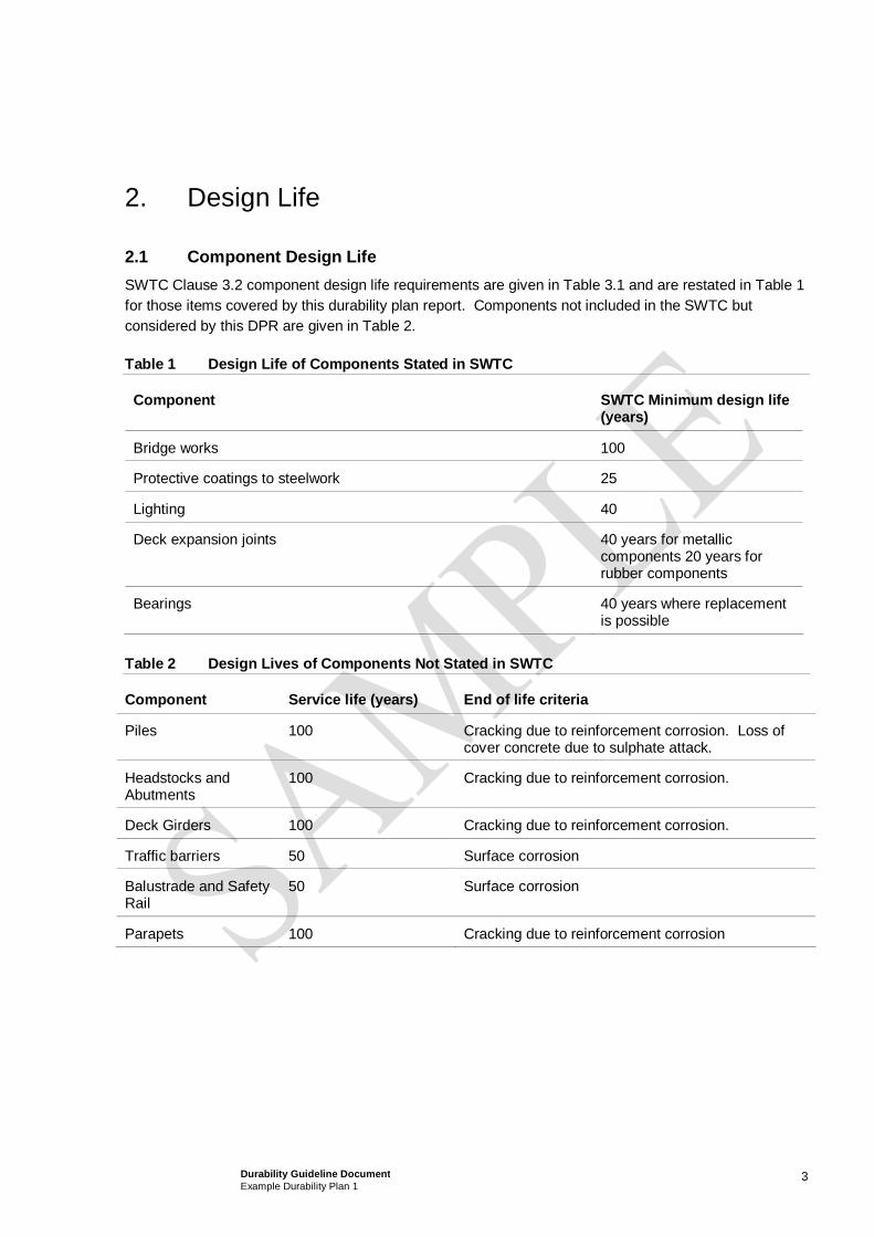
3Durability Guideline DocumentExample Durability Plan 1
2. Design Life
2.1 Component Design LifeSWTC Clause 3.2 component design life requirements are given in Table 3.1 and are restated in Table 1for those items covered by this durability plan report. Components not included in the SWTC butconsidered by this DPR are given in Table 2.
Table 1 Design Life of Components Stated in SWTC
Component SWTC Minimum design life(years)
Bridge works 100
Protective coatings to steelwork 25
Lighting 40
Deck expansion joints 40 years for metalliccomponents 20 years forrubber components
Bearings 40 years where replacementis possible
Table 2 Design Lives of Components Not Stated in SWTC
Component Service life (years) End of life criteria
Piles 100 Cracking due to reinforcement corrosion. Loss ofcover concrete due to sulphate attack.
Headstocks andAbutments
100 Cracking due to reinforcement corrosion.
Deck Girders 100 Cracking due to reinforcement corrosion.
Traffic barriers 50 Surface corrosion
Balustrade and SafetyRail
50 Surface corrosion
Parapets 100 Cracking due to reinforcement corrosion

4Durability Guideline DocumentExample Durability Plan 1
3. Environmental Exposure Classifications
3.1 Environment Designation and DescriptionVarious types of environments are identified and described in Table 3, along with the structurecomponent that is affected.
Table 3 Environment Descriptions
Environment Designation Description ComponentAffected
Environment 1 Soils belowpermanent water
Soils immediately below the creek. Piles
Environment 2 Within permanentwater
Elements of the structure permanentlysubmerged below the water line andabove the creek bed.
Piles
Environment 3 Natural groundbelow water table
The local soils below the peak of thewater table. A region of these soils willbe subject to season wetting and dryingwith the rise and fall of the water table.
Piles
Environment 4 Natural groundabove water table
The local soils above the peak of thewater table. However, still subject tocontamination and wetting due to floodwaters, irrigation and precipitation.Chloride content within soil assumed inthe absence of groundwater and soilchemical tests.
Pile andabutments
Environment 5 Specified fill abovewater table
Fill with no PASS or significant residualsalts (e.g. no chlorides, no sulphates)and neutral pH.
Abutments
Environment 6 Tidal and Splashzone
The region surrounding the mean waterlevel subject to changes in the waterlevel. Includes seasonal variations,frequent flooding and splashing fromwater traffic.
Piles
Environment 7 Spray zone Region immediately above the intertidaland splash zone. Only considered inlocations where wave action generatesspray.
Abutmentsandheadstocks
Environment 8 Atmosphericexposed
Encompasses the atmosphericallyexposed areas that are subject directly orindirectly to rainfall.
Deck,bearings andexpansionjoints

5Durability Guideline DocumentExample Durability Plan 1
3.2 Reinforced Concrete Exposure Classificationsa) The exposure classifications of the various environments have been assessed in accordance with
AS5100.5-2004 Table 4.3.
b) Alternative criteria are given in AS3600 (Reinforced Concrete) and AS2159 (Piling). However, thesestandards only give guidance for achieving a design life of 40-60 years, while AS5100 accounts for adesign life of 100 years.
c) The exposure classification determined for the bridge are summarised below in table 4.
Table 4 Environment Descriptions
Component Classification as given in AS5100 or AS2159
Durability Provisions
Piles B2 50 MPa Concrete
Abutments B2 50 MPa Concrete
Deck B1 40 MPa Concrete
3.3 Groundwater and Creek Corrosion AggressivityThe water quality data from bore holes and the creek is provided in the tender geotechnical surveyreport. The chloride content of the creek is 1800mg/l, and sulphate content is 200mg/l.
The assumed surface chloride levels significantly influence durability modelling of concrete structures inchloride environments. Surface chloride concentrations are primarily related to exposure conditions,assumed surface chloride levels are listed in Table 5 based on previous project experience on anexisting bridge with similar proximity to the open saline water.

6Durability Guideline DocumentExample Durability Plan 1
Table 5 Assumed Surface Chloride Levels
Exposure environment Bridge Element Area Surface ChlorideLevel (% wt conc.)
Atmospheric Deck soffit and above 0.5 %
Splash zone Piers above mean high water level
Headstock soffits & Abutment base atHAT
2.0 %
Tidal Zone Pier surface from mean low water levelto mean high water level
1.0 %
Saturated / Submerged Piers below mean water level 1.0 %
3.4 Creek and Ground Water LevelsCreek and ground water levels given in the tender geotechnical report are used for durability assessmentin this report.
Highest astronomical tide level is 0.3 m below the underside of headstock and abutment level.
Mean high water spring level is 1.024m below the underside of the headstock and abutment level.
Mean low water spring level will expose the full length of the piles above the creek bed.
The ground water table in the vicinity of the bridge is expected to mirror the tide height.
3.5 Location of Open Saline WaterThe location of nearby open saline water is approximately 250 m to the East of the Wallace CreekBridge.

7Durability Guideline DocumentExample Durability Plan 1
4. Deterioration Mechanisms
Deterioration mechanisms for reinforced concrete and steel materials are summarised in Table 6.
More detailed general overview durability issues included in this report as follows:
Reinforced concrete durability at Appendix B.
These deterioration mechanisms were used as the basis for identifying the project specific potentialdurability issues to be addressed in this report.
Table 6 Deterioration Mechanisms Summary
ConstructionElements
Deterioration Mechanism Factors Controlling Rate of Deterioration
ReinforcedandPrestressedConcrete
Chloride induced Corrosion
Carbonation induced corrosion
Macrocell corrosion
Localised corrosion at cracks and joints
Thermal/Restraint and ShrinkageCracking
Environmental characteristics
Concrete mix quality
Crack control
Reinforcement cover
As placed concrete quality, particularlycover, compaction and curing
Joint preparation
Coatings
Concrete Acid Sulphate Soils
Alkali-Aggregate Reactivity
Sulphate attack
Acid attack from contaminatedgroundwater and soil
Soft Water Attack
Delayed Ettringite Formation
Thermal/Restraint and ShrinkageCracking
Environmental characteristics
Aggregate properties
Crack control
Binder type
Concrete quality
Surface preparation
Construction methods
ExposedSteel andOther Metallicobjects
Corrosion
Coating/protection failure
Cathodic protection inference
Stray currents
Fatigue
Wear
Environmental characteristics
Material selection
Dissimilar metals
Detailing
Electrical insulation
Coating selection/maintenance
MovementJoints
Excessive movement leading to poorrunning surface
Concrete cracking, delamination and
Construction sequence (particularlyapproaches and prestress girderconstruction/erection lag time)
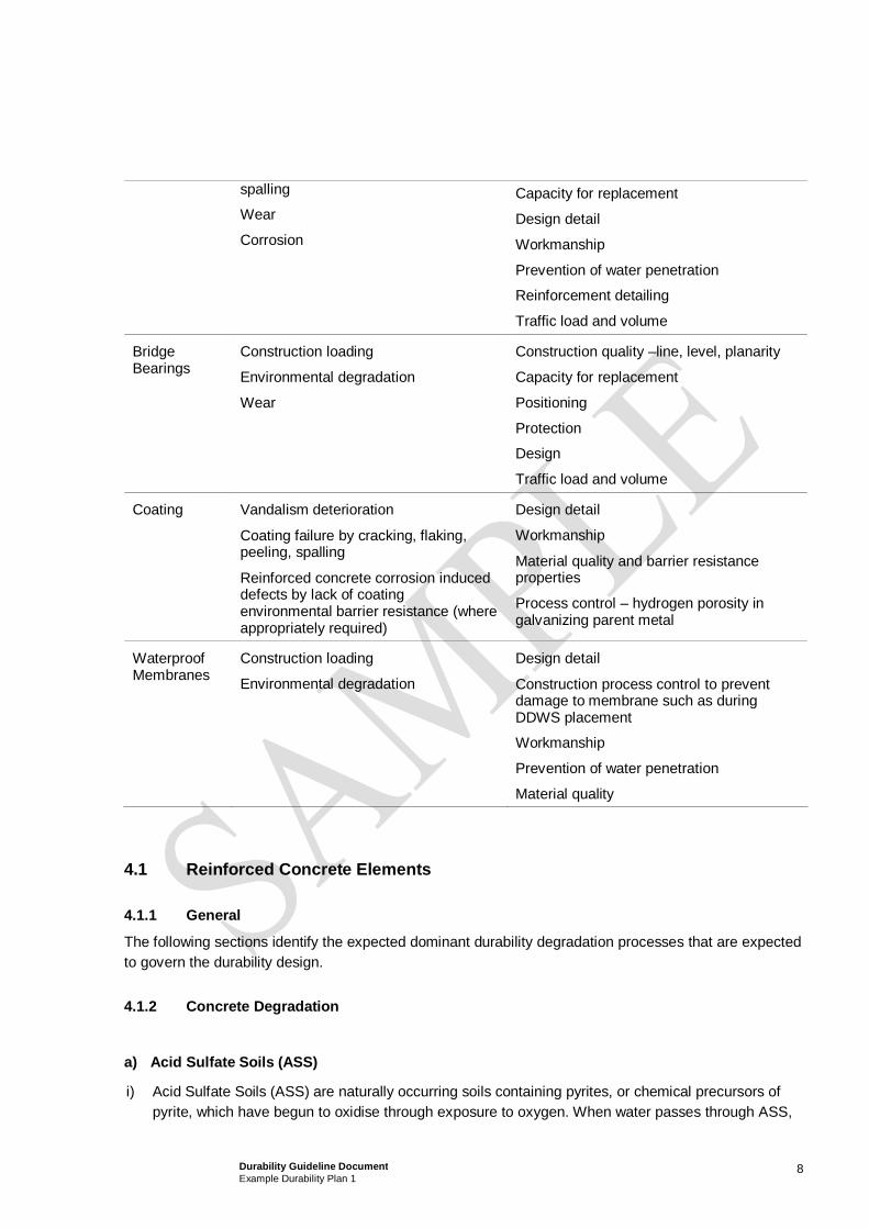
8Durability Guideline DocumentExample Durability Plan 1
spalling
Wear
Corrosion
Capacity for replacement
Design detail
Workmanship
Prevention of water penetration
Reinforcement detailing
Traffic load and volume
BridgeBearings
Construction loading
Environmental degradation
Wear
Construction quality –line, level, planarity
Capacity for replacement
Positioning
Protection
Design
Traffic load and volume
Coating Vandalism deterioration
Coating failure by cracking, flaking,peeling, spalling
Reinforced concrete corrosion induceddefects by lack of coatingenvironmental barrier resistance (whereappropriately required)
Design detail
Workmanship
Material quality and barrier resistanceproperties
Process control – hydrogen porosity ingalvanizing parent metal
WaterproofMembranes
Construction loading
Environmental degradation
Design detail
Construction process control to preventdamage to membrane such as duringDDWS placement
Workmanship
Prevention of water penetration
Material quality
4.1 Reinforced Concrete Elements
4.1.1 General
The following sections identify the expected dominant durability degradation processes that are expectedto govern the durability design.
4.1.2 Concrete Degradation
a) Acid Sulfate Soils (ASS)
i) Acid Sulfate Soils (ASS) are naturally occurring soils containing pyrites, or chemical precursors ofpyrite, which have begun to oxidise through exposure to oxygen. When water passes through ASS,

9Durability Guideline DocumentExample Durability Plan 1
sulphuric acid is leached out. Potential Acid Sulfate Soils (PASS) are similar to ASS in nature but arein an unoxidised state. Engineering operations on ASS and PASS, such as excavation, dredging anddraining accelerate the exposure of pyritic material to air and speeds up the production of acidicwaters.
ii) Critical elements subject to ASS are precast concrete piles and cast in-situ abutments. Precastconcrete piles in particular are prone to ASS attack, and therefore may require isolation using amembrane or coating. Imported clean fill will be used to back fill around abutments, thereforeeliminating the risk of degradation from ASS.
iii) Table 7 summaries the findings from the preliminary PASS Assessment from tender stage. Furthertesting of pH is recommended to confirm site conditions and the need for protective coatings to piles.
Table 7 Acid Sulfate Soils Assessment Summary
ReferenceLocation
Assessment Summary ASS Likelihood PASSLikelihood
IsolationRequired
BH 01 pH generally > 5.5
pHfox generally 3.0 to 6.0
Sulphate content up to0.05%
Possible Possible No
b.) Sulphate Attack
The expected levels of sulphate in the soil and ground water are not considered to be a significant causeof degradation for the buried structures. In addition the chlorides in the groundwater will assist inmitigating the risk of sulphate attack. The cement contents in excess of 400 kg/m3 combined with the useof fly ash will further mitigate sulphate attack.
c.) Alkali Aggregate Reaction (AAR)
In order for AAR to occur, there must be sufficient alkali in the concrete and reactive silica in theaggregate together with moisture to cause the expansion. The approach to mitigate AAR risk is toeliminate one or more of the factors. This is achieved by limiting the alkali content in the concrete mix to2.5 kg/m3 and the inclusion of a minimum 20% fly ash in the concrete. These requirements have beenincorporated into the Concrete Specification.
d.) Backfill & Soil Chemical Induced Deterioration
The back fill materials may contain unacceptable contaminants such as chlorides and sulphates thatinduce reinforcement corrosion or directly attack the concrete. These materials must therefore be testedfor compliance to the specification. As a minimum the tests relevant for reinforcement concrete shallinclude pH, sulphate and chloride content.
e.) Delayed Ettringite Formation (DEF)

10Durability Guideline DocumentExample Durability Plan 1
To mitigate the concerns relating to DEF, the peak concrete hydration temperature must be limited. It iswell established that DEF is unlikely to occur if the concrete temperature is kept below 65oC for GPcement and 75oC for concrete with secondary cementitious materials such as fly ash. Particular riskexists for precast concrete piles and precast deck units due to the steam curing process. Therefore, it isrequired to limit concrete temperature of 65oC for precast elements.
4.1.3 Reinforcement Corrosion
a.) Carbonation Induced Mechanism
The combination of cement content, use of fly ash, low water cement ratio and cover will ensure thatcarbonation induced corrosion of the steel reinforcement will occur well beyond the 100 year service lifefor concrete elements.
b.) Chloride Induced Mechanism
The primary risk of reinforcement corrosion would be chloride induced corrosion. Concrete cover andpermeability would be the prime factors determining the service life of the concrete. Chloride diffusioncoefficient has been specified for some critical elements at risk and this has been checked againstdesign concrete cover with respect to their exposure environment using MTG in-house chloridemodelling software enabling evaluation of the concrete mixes required to achieved to the 100 yeardesign life.Appendix B lists the theoretical background behind the chloride modelling. Table 8 list theassumptions and input parameters for the modelling. Table 10 lists the concrete mix parameters for theproject.
The results of the analysis are summarised below. The expected life is the time to cracking (fromconstruction) of the cover concrete
c.) Acceptably Compacted Concrete Cover
Carbonation and chloride induced reinforcement corrosion both require cover concrete to be wellcompacted with no unacceptable voids, cracks, honeycombing or other defects which would beconfirmed by visual inspection and quality control testing.
All cast in situ elements are to be water cured following formwork removal for a minimum 7 days.Precast elements shall be steam cured followed by application of a 90% efficiency curing compound.

11Durability Guideline DocumentExample Durability Plan 1
Table 8 Durability Modelling Parameters
Parameter Design Value
Atmospheric 0.5 %
Splash zone 2.0
Tidal Zone 1.0%
Surface Chloride Concentration (% by weightconcrete)
Submerged 1.0%
Average Temperature 28oC
Grade of Concrete S50 for insitu and precast concrete.
S80 for piles
Corrosion Activation Threshold* (% by weightconcrete)
0.06% for reinforcement
0.04% for prestressed reinforcement
Cement content (kg/m3) Minimum 400 kg/m3
Cover 50 (35 mm deck units)
Bar diameter Element specific
Table 9 Chloride Modelling Results
Exposure environment Bridge Element Area Time CorrosionInitiation (years)
Time to Cracking(years)
Atmospheric Deck soffit and above 100 140
Splash zone Piers above mean high waterlevel
Headstock soffits & Abutmentbase at HAT
85 110
Tidal Zone Pier surface from mean lowwater level to mean high waterlevel
90 120
Saturated / Submerged Piers below mean water level 90 140

12Durability Guideline DocumentExample Durability Plan 1
Table 10 Concrete Mixes Summary
1) Cement type designations are in accordance with AS 3972. Type GB cement shall contain aminimum 20% fly ash. Pile concrete shall contain a minimum 20% FA and 5% silica fume.
2) Tested by NT Build 443, commencing at 28 days age for GP cement and at 56 days age for blendedcements.
3) Tolerances per AS 1379 Table 6. It should be noted that higher slumps than those shown above maybe specified for particular pours, for example where reinforcement is congested or for deep pours.Slump higher than Table 1 shall be achieved by use of appropriate admixtures and not by increasingwater content and cement content.
4) Stipulated cover is minimum cover. Nominal cover will need to include a tolerance of ±10 mm forinsitu concrete and ±5 mm for precast concrete.
5) Limit steam curing temp to 75oC
4.1.4 Early Age Concrete Thermal/Restraint Behaviour and Crack Risk Assessment
Preliminary assessment of the reinforcement provisions and expected construction method for early agethermal assessment has been undertaken in accordance with CIRIA C660 the results are listed in Table11. The following conclusions from the analysis can be drawn:
Concrete Class S50a S50b S80
In-situ / Precast Insitu Precast Precast
Specific applicable structural element(s)AbutmentsandHeadstocks
PSC BeamsPrecastConcrete Pile
Minimum Cover (mm) (Note 4) 50 35 50
Nominated strength (f’c MPa) 50 50 80
Binder type (Note 1) GB GB GB/SF
Min cement content (kg/m3) 400 400 400
Max cement content (kg/m3) 450 480 550
Max water/binder ratio 0.40 0.38 0.28
Max aggregate size (mm) 20 20 20
Chloride diffusion coefficient (x10-12 m/s2) (Note 2) 2.0 2.0 1.5
Max shrinkage ( ) 600 600 600
Nominal Slump (mm) (Note 3) 80 80 180
Expected Service Life (years) 100 100 100

13Durability Guideline DocumentExample Durability Plan 1
Early age thermal cracking is likely to occur.
C660 predicts that the crack widths at early age will be between 0.13 and 0.18 mm wide. In the longterm some of these cracks may open up to between 0.21 and 0.28 mm but most are likely to remainbelow 0.2 mm.
The reinforcement provided for crack control exceeds the minimum required by AS 5100
A further assessment should be undertaken once the method of construction, timing and concrete mixesare finalised. A hot block shall be cast to obtain adiabatic temperature data for more accurate predictionof cracking risk.
4.2 Bridge BearingsBridge bearings are normally expected to be well protected from the elements by virtue of their positionon the structure. Water ingress through movement joints will be prevented by the elastomeric gland.Moisture collection around the bearing is a possibility, particularly at the more exposed outer bearingsand if the movement joint fails allowing water ingress through the joint. This may cause localiseddegradation, and overtime can lead to the build up of detritus that can promote plant growth. It isproposed to use elastomeric bearings, which can degrade due to UV and moisture exposure. Thebearings will be installed on plinths to prevent direct contact with water on the bearing shelf, and facilitateinspection. In addition the bearing shelf shall be sloped to facilitate drainage and rapid drying.
4.3 Deck Movement Jointsa) Deck movement joints will be fabricated from extruded metal with an elastomeric gland. Industry
common usage and suppliers experience indicates that the glands are the component with theshortest life but are expected to last at least 25 years. The deck joint assemblies are bolted to thedeck and designed to facilitate future replacement.
b) The deck movement joint life would be extended by keeping the joints clean of dirt and debris, whichcollects between the gland surfaces, and can lead to puncture of the gland. Regular cleaning willextend their life.
4.4 Waterproof Membranesa) There is a risk of corrosion to the top steel in the upper surface of the deck units. As this surface
cannot readily be inspected or repaired without significant disruption to the use of the bridge asecondary protective measure of a waterproof coating, Bituthene or similar, will be applied.

14Durability Guideline DocumentExample Durability Plan 1
Table 11 Summary of Early Age Concrete Thermal/Restraint Crack Risk Assessment
Case CaseDescription
ConcreteMixDesign
Restraint PeakTemperature(oC)
PredictedStrain (µ )
Crack ControlReinforcement(provided)
Area ofsteel perface(provided)
Reinforcementrequired (Earlyage cracking,long termcracking) mm2
Early ageThermalCracking(predictedwidth)
1 AbutmentPour 1200mm thick
50 MPa
(25% FA)
0.56 71 192
105
N28 @ 150 EF 4105 2125,3553 0.13 @ 700centres
0.21
2 HeadstockPour 950mmthick
50 MPa
(25% FA)
0.72 71 260
146
N28 @ 150 EF 4105 2125, 3553 0.18 @ 700centres
0.28 @ 700centres

15Durability Guideline DocumentExample Durability Plan 1
4.5 Coating SystemsThe performance of coating systems varies considerably depending on the materials selected. Thefollowing highlights the coating systems used for various elements:
4.5.1 Protective Membrane/Coating for Pile Caps and Precast Concrete Piles
The protective membrane or coating for precast concrete piles is to isolate the concrete from aggressiveacid sulphate soil at selected environmental exposure. The location and extent of coating will beconfirmed following confirmation of site conditions. The fundamental requirement for this coating is toresist a low pH, acid sulphate soil environment and attack to the concrete surface in the long term, sincethe coating is not maintainable. Recommended coating systems include Line-X XS-350 polyurea sprayor equivalent system with extreme chemical and abrasion resistance.
4.5.2 Corrosion Protection Coating for Street Furniture
All exposed metal components for lighting and signage poles will be hot dipped galvanised or primedwith inorganic zinc silicate. The coating will be touched when minor rust staining is observed duringroutine servicing exercises. Some minor corrosion would be expected to develop within 25 years servicelife of the coating. Hot dip galvanising in accordance with AS2312:2002 for a class D environment isrecommended (i.e. HDG900)
4.6 Metal Roadway ElementsItems such as balustrades and safety rails requiring a 50 year design life without maintenance will befabricated from aluminium. Galvanised steel is not expected to provide the required performance giventhe likelihood of salt spray exposure. Grade 316 stainless steel can be considered as an alternative toaluminium by the Client for these items as in addition to good corrosion resistance they will provide ahigh level of aesthetic performance.

16Durability Guideline DocumentExample Durability Plan 1
5. Durability Assessment by Component
5.1 IntroductionA durability assessment was undertaken of each component of the bridge structure. The dominantdeterioration mechanism was identified and protective measures evaluated.
5.2 PilesConcrete piles will be subject to potential acid sulphate soils below ground and saline ground water,saline water in the creek and salt spray above ground.
5.2.1 Within the Creek
The piles will be precast concrete and installed by driving into the creek bed. Splices between piles willbe formed by galvanised steel dowels embedded in 400 mm long core holes. The dowels will be fixedusing epoxy resin. The splice will be protected with a grade 250 hot dipped galvanised steel sleeve. Thesleeve will be grouted into place with epoxy resin.
The soil below the creek bed and below the permanent water table will remain saturated with water andas such the risk of oxidation of the PASS and associated liberation of acid is considered negligible(environment 1 table 3).
The sections of the piles exposed to water within the creek will be exposed to saline conditions and assuch there is a risk of reinforcement corrosion. However where the pile is permanently submerged thecorrosion of the steel reinforcement will be restrained by the availability of oxygen (environment 2).
Above the water line in the intertidal and splash zone (environments 6 and 7) the piles will be exposed toperiodic wetting and drying. This will be the most corrosive exposure environment due to the potential forbuild up of salts on the surface of the pile due to cyclic wetting and drying and the ready availability ofoxygen. This environment will govern the durability design of the piles.
5.2.2 Landside
The piles driven for the abutments are subject to environment 3 and 4. Areas below the water table arerestricted from deterioration for chloride induced reinforcement corrosion owing to the lack of oxygen.Similarly this will restrict oxidation of PASS. For areas above the permanent water table ASS andchloride induced corrosion are a possibility.
Degradation of the concrete due to sulphate attack is also a possibility.
5.3 Abutments and HeadstocksThe cast insitu abutments and headstocks are located in environment 7 and as such are exposed to saltwater spray and splash. To prevent the build up and poling of water on horizontal surfaces the bearingshelf will be sloped to facilitate water shedding and rapid drying.
The risk of ASS to the abutment is considered negligible as clean imported fill will be used to backfillbehind the abutment. Drainage provision behind the abutment will prevent washout of material.

17Durability Guideline DocumentExample Durability Plan 1
5.4 Scour Protection to AbutmentsScour protection to both abutments will be provided in accordance with Main Roads detail MRD1117.
5.5 BearingsBearings will be elastomeric, set atop 200 mm high bearing plinths. These plinths will assist with keepingthe bearing clear of water on the bearing shelf, facilitate inspection and allow sufficient space for jackingto enable bearing replacement. The bearings will be set into a recess in the plinth to prevent excessivelateral movement or “walking”. The horizontal and vertical loading relationship including management ofthe lag time between PSC girder manufacture and erection must be controlled. The expected service lifeof the bearing is 25 years, owing to hardening of the elastomer due to environmental exposure.
5.6 Precast Parapets and Deck UnitsThe deck units and parapets are precast prestressed concrete beams. The deck units are above thewater level in the creek and as such are relatively sheltered (exposure environment 8). The top surfaceof the deck units which will potentially be exposed to moisture penetrating through the deck wearingsurface will be additionally protected with a waterproof coating.
The cut ends of the stressing tendons will be recessed and protected with a greased end cap, andsealed with epoxy resin. This epoxy coating will be inspected on site following delivery and installation,and any damage repaired.
To maintain the sheltered exposure environment under the bridge drip checks will be provided tounderside of parapet units on outer edges. This will prevent water running down the sides of the parapetsand tracking onto the soffit.
5.7 Expansion JointsThe expansion joints will comprise an extruded metal plates and elastomeric gland. The gland isexpected to have a service life of 25 years, and is designed to facilitate replacement. The service life ofthe gland can be reduced if debris, which can puncture the gland, is not removed during annualservicing.
5.8 BallustradeThe balustrade will be fabricated from aluminium. To prevent alkaline induced corrosion of thealuminium the base plate will be insulated from direct contact with the concrete.

18Durability Guideline DocumentExample Durability Plan 1
6. Construction Stage Verification Plan
6.1 GeneralAchievement of the durability objectives are contingent on the insitu construction meeting particularprotective measures.
Table 12 Verification Plan
Component Durability Criteria Method of Verification Acceptance criteria
Concrete grade Cylinder Strengths Compliance with specification
Cover Cover meter survey Meet minimum coverrequirements
Abutments, Precastdeck units, precastpiles andheadstocks.
Cracking /Honeycombing
Visual inspection No honeycombing. No cracksgreater than 0.2 mm in width
Prestressedconcrete deck units
Epoxy coating to cutends of tendons
Visually inspected atprecast yard, delivery tosite and followinginstallation.
Epoxy coating free fromdamage.
Waterproof deckcoating
No defects, blisters,pin holes.Adequately adheredto concrete surface
Visual inspection.
Adhesion testing.
Compliance with specification

19Durability Guideline DocumentExample Durability Plan 1
7. Inspection Requirements
7.1 GeneralThe inspection requirements for the bridge are taken from QDMR Bridge Inspection manual.
7.2 Summary of Inspection Programme
7.2.1 Level 1 inspection
The level 1 inspection is a visual inspection from accessible locations. The deck, expansion joints,parapets, balustrade and crash barrier can be inspected from the deck and pedestrian footway. Ifaccess to the hard shoulder is required traffic management will be required to warn road users of workinglocations.
Access to the abutments and bearings from deck level is provided by stairs constructed into the scourprotection. A flat a paved walkway is provided immediately in front of the abutment for safe access. Theelastomeric bearings are located on bearing plinths to facilitate cleaning and inspection.
Inspection of headstocks and headstock bearings will be from the shore using binoculars or telephotocamera.
The underside of the deck will be visually inspected from the shoreline using binoculars or telephotocamera.
7.2.2 Level 2 & 3 Inspection
The level 2 and 3 inspections require access to be able to touch the structure.
Access to the deck will be from the deck surface. Traffic management to close one lane will be required.It is envisaged that “Stop” and “go” lollipop men positioned at each end of the bridge will be used tocontrol traffic flow to one lane across the bridge. This will facilitate close inspection of the condition ofexpansion joints, balustrade fixings, balustrade and crash barrier condition.
Access to the abutments and bearing will be as for level 1 inspection.
Access to the headstocks will be via boat. The inspection will take place at high tide to facilitate accessto the headstock and bearings. Inspection at low tide will facilitate inspection of the piles in the tidalzone.
Diver inspection of the submerged portions of the piles may be required to check for scour, depending onthe timing of the inspection. However it is envisaged that inspection of the piles will be timed to coincidewith mean spring low water when the water level will drop sufficiently to allow inspection of the creekbed.
The inspection and access requirements are summarised in the table 11 below.

20Durability Guideline DocumentExample Durability Plan 1
Table 13 Inspection Requirements
Component Activity Access
Piles QDMR Level 1 –
Visual inspection
Boat/foot
QDMR Level 2 –
Visual inspection plus photos to within 3 mor telephoto equivalent
Boat/foot plus telephoto
QDMR under water Boat/diver/under water camera
QDMR Level 3 –
Chloride and Carbonation sampling andtesting, selected locations
Delamination survey, selected location
Boat required to access pier increek.
Abutments QDMR Level 1 –
Visual inspection
Foot via walkway in front ofabutment
QDMR Level 2 –
Visual inspection plus photos to within 3 mor telephoto equivalent
Foot via walkway in front ofabutment
QDMR Level 3 –
Chloride and Carbonation sampling andtesting, selected locations
Delamination survey, selected location
Foot via walkway in front ofabutment
Concrete deck soffit QDMR Level 1 –
Visual inspection
Boat/foot and shore based
QDMR Level 2 –
Visual inspection plus photos to within 3 mor telephoto equivalent
Boat/foot and shore based withtelephoto.
QDMR Level 3 –
Close visual inspection plus testing forcarbonation/chlorides
Underside of deck can beviewed at high tide from a boat.Sampling from deck taken fromshore at abutments or underbridge inspection unit.
Street Furniture Visual inspection for corrosion or damage Footway
Bearings and joints QDMR Level 1 –
Visual inspection
Foot via walkway in front ofabutment or from pedestrianfootpath
QDMR Level 2 –
Visual inspection
Foot via walkway in front ofabutment

21Durability Guideline DocumentExample Durability Plan 1
QDMR Level 3 – Foot via walkway in front ofabutment. Inspection of themovement joint will require trafficmanagement.
Ballustrade Visual inspection for corrosion and damage Via pedestrian footpath and hardshoulder.

22Durability Guideline DocumentExample Durability Plan 1
8. Servicing & Maintenance Requirements
8.1 GeneralThe expected maintenance and servicing requirements are in accordance with QDMR Bridge ServicingManual.
8.2 Servicing and Maintenance
8.2.1 General
The following anticipated maintenance activities are identified and method of access described. Inaddition to the planned regular maintenance programme, additional maintenance may be requiredfollowing flooding or accidents.
Following flooding events that result in the creek level rising to bearing level or higher the bridge shouldbe checked for damage and any debris removed. Similarly the structure should be checked for damagefollowing bridge strikes or road traffic accidents on the bridge and any damage rectified.
Table 14 Maintenance Requirements
Component Activity Frequency Access
Piers andHeadstocks
Washing 12 mths Under bridge inspectionunit. Single lane trafficrequired over bridge.
Abutments Washing 12 mths Via walkway in front ofabutment
Drainage Rodding, flushing andcleaning
12 mths Drainage channels can beaccessed from the deck.
Abutment drainage can beaccessed from under thedeck via the walkway infront of the abutment.
Ballustrade Washing 12 mths Via pedestrian walkway.
Bearings andjoints
Cleaning and removal ofdebris around bearingshelf. Removal of debrisfrom movement joint.
12 mths Via pedestrian walkway.

23Durability Guideline DocumentExample Durability Plan 1
9. Replacement Requirements
9.1 GeneralBased on the durability assessment described in this report the service life of the following componentsis expected to be less than the required 100 year design life of the structure, and therefore theseelements will require replacement.
Table 15 Component Replacement Summary
Component Expected Service Life Replacement Trigger Levels
Elastomeric Bearings 40 Cracking, splitting of theelastomer, or excessivedistortion.
Expansion Joints 40 for metallic components, 20years for rubber components
Cracking or splitting of gasket.Corrosion of locating bolts.
Ballustrade 50 Pitting corrosion of balustrade.Corrosion of holding down bolts.
9.2 BearingsThe elastomeric bearings are predicted to have a useful life of 25 years.
9.2.1 Replacement Trigger levels
The degradation of the elastomer, due to UV exposure and weathering will result in hardening of thebearing. Cracking or splitting of the bearing may also occur.
When the hardness of the bearing, as tested by penetration hardness, exceeds the manufacturer’s limitsthe bearing should be replaced.
9.2.2 Replacement Methodology
The bearing replacement method and equipment required is detailed on drawing 119563.
9.3 Movement JointThe elastomeric gland of the movement joint is expected to have a service life of 25 years, provided it isregularly maintained.
9.3.1 Replacement Trigger levels
Degradation of the gland is expected to be caused by UV exposure or puncture from debris. Minorpuncture damage can be repaired by application of a suitable sealant.

24Durability Guideline DocumentExample Durability Plan 1
9.3.2 Replacement Methodology
The movement joint is designed to facilitate removal and replacement at the end of its service life. Thebridge will need to be closed to traffic during replacement activities.
The epoxy protection to holding down bolts shall be removed, the retaining bolts removed to facilitateremoval of the joint. The threaded bolts are fabricated from 316 stainless steel, and it is expected thatthese bolts will not normally need replacement. The new movement joint can be installed using theexisting holding down bolts. Damaged bolts can be replaced by over coring and fixing a replacement boltin place with epoxy resin.
9.4 BalustradeThe balustrade is expected to have a service life of 50 years.
9.4.1 Condition State Guideline
Owing to the saline environment the balustrade is expected to deteriorate due to atmospheric corrosion,resulting in the pitting of the surface.
9.4.2 Replacement Methodology
The balustrade and safety rail can readily be replaced by removing the holding down bolts. At this time ifcorrosion to the bolts is noted they should be removed by over coring and replaced with new bolts fixedin place with resin epoxy.

25Durability Guideline DocumentExample Durability Plan 1
10. Durability Plan Summary Tables
The durability design described in this DPR is summarised in QDMR standard Summary tables inAppendix A

26Durability Guideline DocumentExample Durability Plan 1
11. Construction Phase DPR Compliance Assessment
Durability Compliance will be in accordance with the requirements of Tables 10. A durability verificationreport will be submitted on completion of construction.

Durability Guideline DocumentExample Durability Plan 1
Appendix A
Durability Design Summary Tables

Duration (years)
Contract Reference
Potential Mode of Failure Deterioration Mechanism Factors Controlling Rate ofDeterioration
End of Life Criteria (Expected governing failure mechanism)
Chloride induced
Carbonation induced
Macrocell corrosion
Localised corrosion at cracksand jointsChloride induced
Carbonation induced
Macrocell corrosion
Localised corrosion at cracksand joints
Balustrade 50 years Project Specification requires 100 year design life
Surface corrosion Pitting corrosion Environmental characteristics Through corrosion or deep pitting of surface.
Elastomeric Bearings 25 years Project Specification requires 100 year design life
Cracking and/or bulging of bearing. Hardening of elastomer.
Oxidation and exposure to UV light.
Environmental characterisitics and composition of elastomer
Excessive bulging and/or cracking or splitting
Loss of water tightness Oxidation and cracking of elastomer
Environmental characterisitics and composition of elastomer
Puncture of sealant
Puncture of elastomerChloride induced
Carbonation induced
Localised corrosion at cracks and joints
Table Legend
Table 1 Table 2 Table 3 Table 4 Table 5 Table 6 Table 7 Table 8
Environmental characteristicsConcrete mixCrack controlReinforcement coverAs placed concrete qualityJoint preparation
chloirde induced reinforcement corrosion
100 years Project Specification requires 100 year design life
Reinforcement Corrosioninduced cracking,delamination and spalling ofreinforced concrete
Abutments and Headstocks 100 years Project Specification requires 100 year design life
Reinforcement Corrosioninduced cracking,delamination and spalling ofreinforced concrete
Table 1: Structure Durability Outline
Critical Durability Components
Service Life
Environmental characteristicsConcrete mixCrack controlReinforcement coverAs placed concrete qualityJoint preparation
chloirde induced reinforcement corrosion
Piles
Reinforcement Corrosion induced cracking, delamination and spalling of concrete
Environmental characterisitics, Concrete mix, Crack control, reinforcement cover, joint preparation, quality of concrete placement.
Carbonation induced reinforcement corrosion
Expansion Joints 25 years Project Specification requires 100 year design life
Deck 100 years Project Specification requires 100 year design life
Table 1Page 1

No. Zone1 Below River
premanent water level
Chloride Concentration 1800mg/l, Sulphate Concentration 200 mg/l, pH
6.5
concrete piles Chloride Induced corrosion, Sulphate attack of concrete
50 MPa concrete Cement content, water cement ratio and quantity of cement replacement inadequate to achieve 100 year life.
Concrete mix to have low W/c ratio, minimum cement content, and Fly Ash.
2 Within Creek below water
level
As above concrete piles Reinforcement corrosion due to saline water and oxygen supply.
50 MPa concrete Cement content, water cement ratio and quantity of cement replacement inadequate to achieve 100 year life.
Concrete mix to have low W/c ratio, minimum cement content, and Fly Ash.
3 Below Water table
As above concrete piles Reinforcement corrosion due to saline water and oxygen supply.
50 MPa concrete Cement content, water cement ratio and quantity of cement replacement inadequate to achieve 100 year life.
Concrete mix to have low W/c ratio, minimum cement content, and Fly Ash.
4 In ground above water
table or retaining ground
PASS, ASS, chlorides and sulphates Abutments and piles No Potential Acid Sulphate Soils (PASS) have been identified by investigations to date but would require confirmation.
50 MPa concrete yes, subject to confirmation of ASS and PASS conditions.
Concrete to contain Fly Ash
5 Specified Fill Above Water
No agressive agents expected. Clean fill to be used.
Abutments None. AS3600 50MPa concrete, minimum cover 50mm
Yes.
6 Intertidal and Tidal and
Splash Zone
Surface Chloride Concentration 4% concrete piles, abutments and headstocks
Chloride Induced corrosion 50 MPa concrete No Concrete mix to have low W/c ratio, minimum cement content, and Fly Ash.
7 Spray Zone Surface Chloride Concentration 6% concrete piles, abutments and headstocks
Chloride Induced corrosion 50 MPa concrete No Concrete mix to have low W/c ratio, minimum cement content, and Fly Ash.
Carbon dioxide Deck Units Chloride or carbonation induced corrosion
50 MPa concrete Yes None
Wind borne chlorides Bearings Hardening and cracking of elastomeric components
n/a Allow for replacement
Balustrade Chlroide induced pitting corrosion
n/a Allow for replacement
UV expsoure Expansion Joints Puncture of gland. Corrosion of metallic components
n/a Allow for replacement
Table 1 Table 2 Table 3 Table 4 Table 5 Table 6 Table 7 Table 8
Assess if Code Sufficient Identified Additional Requirements
Environment Potential Deterioration Mechanisms
Code Requirements Affected Structural ComponentsEnvironmental Details
Table Legend
Table 2: Component Exposure Assessment (All Components)
8 Atmospheric Exposure
2 Table 213/10/2009

No. Zone 1 Below River
premanent water level
concrete piles Chloride Induced corrosion, Sulphate attack of concrete
S80 concrete containing 20% FA and 5% SF. Minimum cover 50 mm. Steam cured. Maximum water cement ratio 0.28. Minimum cover of 50 mm.
Visual inspection for surface defects. Cover meter survey to confirm minimum cover requirements achieved.
2 Within Creek below water level
concrete piles Reinforcement corrosion due to saline water and oxygen supply.
as above
3 Below Water table
concrete piles Reinforcement corrosion due to saline water and oxygen supply.
as above
4 In ground above water table or retaining ground
Abutments and piles No Potential Acid Sulphate Soils (PASS) have been identified by investigations to date but would require confirmation.
S50 concrete containing 20% FA. Minimum cement content 400 kg/m3, maximum water / cement ratio 0.4. Chloride diffusion coefficient of 5e-12 m/s/s. Maximum shrinkage 600 micro strain. Minimum cover of 50 mm.
Thermal modelling to be undertaken prior to construction on site to confirm design assumptions. 7 days wet curing.
Visual inspection for surface defects. Cover meter survey to confirm minimum cover requirements achieved.
5 Specified Fill Above Water Table
Abutments None.
6 Intertidal and Tidal and Splash Zone
concrete piles, abutments and headstocks
Chloride Induced corrosion S50 concrete containing 20% FA. Minimum cement content 400 kg/m3, maximum water / cement ratio 0.4. Chloride diffusion coefficient of 5e-12 m/s/s. Maximum shrinkage 600 micro strain. Minimum cover of 50 mm.
Thermal modelling to be undertaken prior to construction on site to confirm design assumptions. 7 days wet curing.
Visual inspection for surface defects. Cover meter survey to confirm minimum cover requirements achieved.
7 Spray Zone concrete piles, abutments and headstocks
Chloride Induced corrosion
8 Atmospheric Exposure
Deck Units Chloride or carbonation induced corrosion S50 concrete containing 20% FA. Minimum cement content 400 kg/m3, maximum water / cement ratio 0.38. Chloride diffusion coefficient of 6e-12 m/s/s. Maximum shrinkage 600 micro strain. Minimum cover of 35 mm. Application of waterproof coating to top surface.
Steam curing followed by application of curing compound.
Visual inspection for surface defects. Cover meter survey to confirm minimum cover requirements achieved.
Table 1 Table 2 Table 3 Table 4 Table 5 Table 6 Table 7 Table 8
Table Legend
Validation Measure/Test
Table 3: Durability Provisions for Critical Components - Design Phase
Environment Classification
Construction Contract ProvisionDesign Mitigation MeasureIdentified Deterioration MechanismsAffected Structural Components
3 Table 313/10/2009

Affected Structural Component
Environment No.
Zone Activity Frequency Access Provision
Intervention Level
Activity Frequency Access Provision
Elastomeric Bearings
8 Atmospheric Exposure Cleaning bearings. Visual Inspection.
12 months Paved footway in front of abutment.
Cracking of elastomer. Hardening of elastomer.
Hardness testing of elastomer.
10 years for hardness testing.
Jacking points on bearing shelf and deck units have been provided.
Drainage 8 Atmospheric Exposure Cleaning and flushing of drainage
12 months From deck surface or walkway in front of abutment.
Balustrade 8 Atmospheric Exposure Cleaning 12 months From predestrian footpath
Movement joints 8 Atmospheric Exposure Debris removal 12 months From deck surface or walkway in front of abutment. Traffic management to close one lane required.
Abutments and headstocks
7 Spray Zone Washing 12 months UBIU parked on hard shoulder of bridge. Traffic management required.
Table Legend
Table 1 Table 2 Table 3 Table 4 Table 5 Table 6 Table 7 Table 8
Table 4: Maintenance Intervention Assumptions (to achieve service life)
CyclicServicingElement
4 Table 413/10/2009

Affected Structural Component
Environment No.
Zone Description Mitigation
Elastomeric Bearings
8 Atmospheric Exposure
Hardening of elastomer. Spliting, tearing of shearing os bearing.
Annual - QDMR Level 1 – visual inspection. At 5 years - QDMR Level 2 –Visual inspection plus photos to within 3m or telephoto equivalent. At 10 years QDMR Level 3 - hardness testing of elastmoeric bearing
Hardness testing of elastomeric bearing
Foot access from road level to front of abutment.
Slip and fall hazard ascending and descending embankment.
Paved stairway with hand rail up to abutment. Paved footway in front of abutment.
Piles 6 Intertidal and Tidal and
Splash Zone
Cracking and corrosion staining, delamination and spalling
QDMR level 1, 2 and 3 inspections at the frequency stated above.
QDMR Level 3 inspection at 10 years - Chloride profile testing of piles in splash zone to confirm expected durability performance.
Visual inspection from shore. Sampling from UBIU or boat access.
Working over a water way.
Abutments 7 Spray Zone Cracking and corrosion staining, delamination and spalling
QDMR level 1, 2 and 3 inspections at the frequency stated above.
QDMR Level 3 inspection at 10 years - Chloride profile testing of piles in splash zone to confirm expected durability performance.
Foot access from road level to front of abutment.
Slip and fall hazard ascending and descending embankment.
Paved stairway with hand rail up to abutment. Paved footway in front of abutment.
Headstocks 7 Spray Zone Cracking and corrosion staining, delamination and spalling
QDMR level 1, 2 and 3 inspections at the frequency stated above.
QDMR Level 3 inspection at 10 years - Chloride profile testing of piles in splash zone to confirm expected durability performance.
Visual inspection from shore. Sampling from UBIU or boat access.
Working over a water way.
Balustrade 8 Atmospheric Exposure
Deep pitting corrosion QDMR level 1, 2 and 3 inspections at the frequency stated above.
None Access from pedestrian footpath
Street furniture
8 Atmospheric Exposure
Rust staining on surface QDMR level 1 and 2 inspections at the frequency stated above.
None Access from pedestrian footpath
Movement joints
8 Atmospheric Exposure
Splits in elastomeric gland. QDMR level 1 and 2 inspections at the frequency stated above.
None Access from deck. Access into roadway required for close inspeciton of joint.
Traffic management required to close one lane of traffic.
Precast Concrete Bridge Beams
8 Atmospheric Exposure
Cracking and corrosion staining, delamination and
spalling
QDMR level 1, 2 and 3 inspections at the frequency stated above.
Chloride and carbonation sampling and testing to confirm durability performance. Delamination survey.
UBIU Parked on hard shoulder. Traffic Management required to close near side lane.
Reduced headroom to river traffic under bridge when UBIU in use.
Close road while inspection in progress.
Table 1 Table 2 Table 3 Table 4 Table 5 Table 6 Table 7 Table 8
Table 5: Inspection & Access Provisions
Condition State Guidelines
Table Legend
Supplementary Requirements to BIM
Safety HazardsElement Inspection Requirement Access
5 Table 513/10/2009

Affected Structural Component
Environment No.
Zone Description Mitigation
Elastomeric bearings
8 Atmospheric Exposure
25 Hardening of elastomer. Spliting, bulging or tearing of elastomer. Excessive lateral movement of bearing.
Provision of bearing plinths and jacking points for lifting deck and replacement of bearings.
Method statement for bearing replacement and drawings provided. Drawing ref 119563
Paved walkway in front of abutment can be used as working platform.
Collapse of jacks during lifting operations.
Using Flat Jacks
Balustrade 8 Atmospheric Exposure
50 Deep pitting corrosion. Balustrade holding down bolts are designed to facilitate removal and replacement of corroded or damaged balustrade.
None Pedestrian footpath.
Hazard to public during replacement activities.
Footpath to be closed to public, and traffic lane nearest woring are to be closed.
Movement Joints
8 Atmospheric Exposure
25 Cracking, splitting or tearing of elastomeric gland.
Stainless steel holding down bolts area provided to facilitate removal and replacement of the movement joint.
None Access to movement joint from deck surface.
Passing traffic Traffic management to include safe working area.
Table 1 Table 2 Table 3 Table 4 Table 5 Table 6 Table 7 Table 8
Table Legend
Element Condition State Guidelines
Design Provisions
Table 6: Replacement of Components
Maintenance Plan & Drawing References
Access Safety HazardsReplacement Frequency (years)
6 Table 613/10/2009

Component Description
Manufacturer Details
Product reference Servicing Requirements
Warranty Installation Details
Deck Expansion Joint
Miska Miska BJ 1 expansion joint
Inspect and remove debris every 12 months. Replace or repair damaged glands.
To be provided by construction contractor.
To be provided by construction contractor.
Bearing To be provided by construciton Contractor
Inspect, clean and remove debris every 12 months.
Waterproof membrane
To be provided by construciton Contractor
Table Legend
Table 1 Table 2 Table 3 Table 4 Table 5 Table 6 Table 7 Table 8
Table 7: Proprietary Product Records
7 Table 713/10/2009

Intervention LevelNo. Zone Location Description Location Description
1 Below River premanent water level
Piles Chloride Induced corrosion, Sulphate attack of concrete
S80 concrete containing 20% FA and 5% SF. Minimum cover 50 mm. Steam cured. Maximum water cement ratio 0.28. Minimum cover of 50 mm.
Visual inspection for surface defects. Cover meter survey to confirm minimum cover requirements achieved.
Cover less than specified minimum. Cracking inexcess of 0.2mm wide. Honey combing.
7 Spray Zone Abutments Chloride Induced corrosion S50 concrete containing 20% FA. Minimum cement content 400 kg/m3, maximum water / cement ratio 0.4. Chloride diffusion coefficient of 5e-12 m/s/s. Maximum shrinkage 600 micro strain. Minimum cover of 50 mm.
Thermal modelling to be undertaken prior to construction on site to confirm design assumptions. 7 days wet curing.
Visual inspection for surface defects. Cover meter survey to confirm minimum cover requirements achieved.
Cover less than specified minimum. Cracking inexcess of 0.2mm wide. Honey combing.
7 Spray Zone Headstocks Chloride Induced corrosion S50 concrete containing 20% FA. Minimum cement content 400 kg/m3, maximum water / cement ratio 0.4. Chloride diffusion coefficient of 5e-12 m/s/s. Maximum shrinkage 600 micro strain. Minimum cover of 50 mm.
Thermal modelling to be undertaken prior to construction on site to confirm design assumptions. 7 days wet curing.
Visual inspection for surface defects. Cover meter survey to confirm minimum cover requirements achieved.
Cover less than specified minimum. Cracking inexcess of 0.2mm wide. Honey combing.
8 Atmospheric Exposure
Deck units S50 concrete containing 20% FA. Minimum cement content 400 kg/m3, maximum water / cement ratio 0.38. Chloride diffusion coefficient of 6e-12 m/s/s. Maximum shrinkage 600 micro strain. Minimum cover of 35 mm. Application of waterproof coating to top surface.
Steam curing followed by application of curing compound.
Visual inspection for surface defects. Cover meter survey to confirm minimum cover requirements achieved.
Cover less than specified minimum. Cracking inexcess of 0.2mm wide. Honey combing.
Table 1 Table 2 Table 3 Table 4 Table 5 Table 6 Table 7 Table 8
Table 8: Durability Provisions for Critical Components - Construction & Service Phases Records and Departures
Table Legend
Validation RecordsConstruction Contract Provision Defect RecordsValidation Measure/Tests (departures to be added)
Construction or Repair Method Environment Affected Structural Components Identified Deterioration Mechanisms Design Mitigation Measure
8 Table 813/10/2009

Durability Guideline DocumentExample Durability Plan 1
Appendix B
Reinforced Concrete DurabilityCommentary

Durability Guideline DocumentExample Durability Plan 1
General Overview of Reinforced Concrete Durability IssuesPurpose: This general overview is used for review to identify the project specific durability issues. Thecontent is therefore general for all possibilities.
1. Reinforcement Corrosion
The two principal interactive materials steel reinforcement and concrete are subject to separate butinterrelated deterioration processes. Steel embedded in concrete is normally protected from corrosion bythe existence of a passive oxide film surrounded by calcium hydroxide (Ca(OH)2), the latter reflecting thehighly alkaline environment of fresh concrete where a pH in excess of 12.5 can be anticipated. The twomaterials thus combine to form a deterioration resistant composite.
The integrity of this composite can be affected by the deterioration of either material or both materials inunison. The deterioration of steel inside concrete is a corrosion process, which can be initiated by one orboth of two mechanisms.
a) Chloride contamination: the presence of a critical concentration of chloride ions at thereinforcement surface will cause local breakdown of the passive layer, even at a high pH. Instructures exposed to a saline environment this is the primary corrosion risk for the reinforcedconcrete.
b) Carbonation: the gradual penetration of atmospheric carbon dioxide in unsaturated concrete willneutralise the protective alkaline environment surrounding embedded steel. If moisture is present,the steel will corrode.
Once initiated, the rate of corrosion is a complex function of several factors including the availability ofoxygen and the overall electrical resistance between anodic and cathodic sites. Corrosion is anelectrochemical reaction, or more accurately, two half cell reactions:
At the anode Fe Fe 2+ + 2e
At the cathode 1/202 + H2O + 2e 20H
These two reactions must be balanced (i.e. the rate of generation of electrons at the anode must equalthe rate of consumption at the cathode). Therefore the rate of the overall loss of metal at the anode isdependent on the rate at which both half cell reactions can occur. This is important in an assessment ofcorrosion risk in concrete elements as will be demonstrated below. It should be noted from the abovethat oxygen is (normally) required at cathodic sites in order for the reactions to proceed.
Secondary reactions at the anodic site convert Fe2+ ions into oxide compounds, the exact form of whichdepends largely on the availability of oxygen at the anode. In atmospheric conditions where oxygen isplentiful, the normal reactions will be generation of a hydrated iron oxide:
2Fe(OH)3 Fe203 . (xH2O)
These hydrated oxides occupy a greater volume that the iron dissolved in their production by a factorbetween 2 and 4, hence creating expansive forces in the surrounding concrete. When these forcesexceed the tensile capacity of the cover concrete, cracking and/or spalling occurs.
This is the typical scenario in an atmospheric reinforced concrete element exposed to saline water.Chloride ions penetrate the cover and adjacent anodic and cathodic sites develop as passivity breaks

Durability Guideline DocumentExample Durability Plan 1
down. Micro cells are formed with anodic sites (usually in the form of pits) and immediately adjacentcathodic sites supplied with oxygen via diffusion of air through the cover. A similar process occurs inatmospheric conditions in which carbonation of the concrete induces corrosion, although a differentcorrosion product results.
In concrete elements in which the section is totally saturated, the corrosion process is controlled by alack of oxygen, thus limiting the rate of reaction. Although some oxygen is present in saline water, theslow rate at which it can be diffuse through the concrete cover results in what amounts to oxygenstarvation conditions. Thus, although corrosion is often initiated in submerged conditions, it does notproceed at a rate, which leads to significant metal loss, and therefore can be discounted in most cases.
An intermediate condition arises in concrete elements which are water excluding. In this case salinewater on one side can penetrate the cover and create anodic sites. The potential difference between thetwo grids of steel, and oxygen access from the inside wall, means the cathodic sites can develop.Because oxygen is not readily available at the anodic sites, the secondary reaction is severely limitedand the formation of expansion oxides is minimal. However metal loss will still occur, with eventualstructural consequences if the corrosion rates are significant.
This process is known as macro cell corrosion and has been considered the theoretical corrosion risk forUnited Kingdom North Sea hollow leg concrete platforms. Although this mechanism undoubtedly occursit is difficult to assess its rate. The rate is dependant on the total electrical resistance of the corrosioncircuit.
Another mechanism for reinforcement corrosion is stray DC traction currents from nearby rail and tramsystems. Modern traction systems are generally designed to minimise the levels of stray current leakageto earth from the rail. This is generally achieved by the installation of insulators under the rail to increasethe resistance of the rail to earth.
Metallic structures buried in the ground may be subject to stray current interference, and subsequentcorrosion, in the vicinity. The susceptibility of a structure to stray current corrosion will be dependantupon the geometry and size of the structure, any coatings applied to the structure, the conductivity of theenvironment surrounding the structure, the proximity of the structure to both the traction rail line and thetraction electrical substation.
Stray DC currents will find the lowest resistance path back to the source. (i.e. where the power isgenerated at the substation). Modern traction vehicles utilise regeneration braking to increase theefficiency of the operation traction system. Regenerative braking utilises the energy “stored” in themoving traction vehicle, to regenerate power into the system when the rail vehicle is braking. Thisimplies that each rail vehicle will act as a substation in the system under braking. The magnitude of thecurrent “escaping” is a function of the length of the rail, the leakage resistance to earth of the rail, and thecurrent loading per unit length of the track.
When current arrives at the reinforcement, the reinforcement electrical potential will become morenegative than the steel’s natural potential. At a reinforcement discontinuity, the current leaves thestructure and returns into the soil on its circuitous path to the substation (supplying the positive return),resulting in a more positive electrical potential at the point of discontinuity. This results in stray currentcorrosion at the site of steel discontinuity.
2. Concrete Deterioration

Durability Guideline DocumentExample Durability Plan 1
Concrete deterioration can occur without reinforcement corrosion, albeit the processes involved mayeventually initiate or accentuate corrosion mechanisms. Main concerns are:
a) Alkali Aggregate Reaction (AAR)
b) Sulfate Attack
c) Acid Attack
d) Microbiologically Induced Attack
e) Aggressive Carbon Dioxide
f) Magnesium Attack
g) Delayed Ettringite Formation (DEF)
2.1 Alkali Aggregate Reaction (AAR)
Alkali aggregate reaction (AAR) is a chemical process in which alkalis, present in cement, combine withcertain compounds in the aggregate when moisture is present. The reaction produces an alkali-silica gelthat can absorb water and expand to cause cracking and disruption of the concrete. For alkali-silicareaction and damaging expansion of the resulting gel to occur in hardened concrete, it is necessary tohave the occurrence of the following three elements:
a) A sufficiently concentrated pore solution
b) A proportion of reactive silica or silicate in the aggregate
c) Sufficient moisture in the concrete
Previous project experience has indicated that North Queensland aggregates exhibit varying degrees ofreactivity. Special assessment of aggregates for AAR is normal practise in major projects and approvedconcrete suppliers should have petrographic assessment records for review prior to mix design approval.
In instances where laboratory testing of aggregates (peterographic analysis) indicates a certain degree ofreactivity measures to reduce the risk of ASR deterioration shall be incorporated in the mix design.These include either or a combination of the following (as listed in Table 4 SAA HB79-1996) using analternative aggregate source, limiting the alkali content within mix and using blending cements.
2.2 Sulfate Attack
Two principal chemical reactions between sulfates present in the groundwater and the concrete areattributed to sulfate attack:
a) A reaction between the sulfates and calcium hydroxide to produce calcium sulfate (or gypsum). Thevolume of the gypsum produced is more than double the volume of the calcium hydroxide reaction.This gives rise to internal stresses, which break down the concrete.
b) Consumption of lime as above lowers pH, allowing sulfate to react with destabilised aluminateminerals in the current paste to form an expansive mineral, ettringite, which results in breakdown ofthe cement paste.

Durability Guideline DocumentExample Durability Plan 1
These reactions lead to expansion and disruption of the concrete. Ultimately, the concrete is reduced toa soft and friable state.
Factors that influence the rate of sulfate attack of concrete include:
a) Concentration and type of sulfate and the pH of the water;
b) Mobility of the sulfate contaminated water;
c) Penetrability, cement type and content, water/cement ratio of the concrete.
The type of sulfate is most important in respect to the extent and rate of sulfate attack of concrete. Forexample, magnesium sulfate has a more aggressive action than other sulfates and decomposes thehydrated calcium silicate cement phases in addition to reactions (a) and (b) described above.Ammonium sulfate is more aggressive than sodium sulfate because of the increased solubility of thegypsum in ammonium sulfate solutions and formation of the ammonia gas which allows reaction (a) and(b) proceed to completion.
The pH of the sulfate solution is important, since more extensive and more rapid rate of attack occurs atlow pHs. Acid dissolution (neutralisation) of the cement paste occurs in combination with sulfate attack.The type(s) of acid also influences the degree and rate of the attack.
The flow rate of groundwater affects durability since a mobile groundwater will remove the products ofreaction and replenish the sulfate attack site with more aggressive media. Specific flow rates are notquoted in the literature and standards, although standards such as AS 2159-1995 differentiate theaggressiveness of groundwater according to “high” permeability and “low permeability” soils.
Concrete quality aspects such as cement type and content, penetrability and water/cement ratio have amarked affect on the degree and rate of sulfate attack. Blast furnace slag, fly ash and silica fumeblended cement based concretes have been found to be more resistant to sulfate attack than sulfateresisting Portland cement concretes. Increasing cement content and decreasing water/cement ratio hasthe effect of lowering the water penetrability of a concrete, which leads to decreased sulfate attack.
Depending on the form of concrete construction, shrinkage and thermal cracking aspects limit the extentto which cement content can be increased. Similarly, construction issues such as placability,compactibility, etc limit the extent to which the water/cement ratio of a concrete can be decreased. Thepenetrability of a concrete is also affected by construction aspects such as compaction, method of cure,curing period, etc.
Low sulfate concentration in the ground water within the construction area of a project will result insulfate attack not being a major environmental risk.
2.3 Acid Attack
Acids in general are considered to be problematical for concrete when the pH falls below 6.5 forprolonged periods. The key break down mechanism is outlined below.
The reduction of pH due to consumption of calcium hydroxide destabilises the calcium aluminatehydrates and the calcium silicate hydrates in the cement paste, resulting in breakdown of thesecementing minerals.

Durability Guideline DocumentExample Durability Plan 1
Ultimately the integrity of the concrete is diminished and the surface concrete gradually erodes with time.Factors that influence the rate of acid attack of concrete include:
a) Concentration and type of acid;
b) Mobility of the acid contaminated water;
c) Penetrability, cement type and content, water/cement ratio of the concrete
d) Aggregate type (not significant with local aggregates)
The type of acid is most important with respect to the extent and rate of the attack of concrete. Forexample, sulfuric acid attack is particularly destructive since mechanisms discussed in the Section 2.2Sulfuric Attack, will also be active.
The flow rate of ground water affects durability since a mobile groundwater will remove the products ofreaction and replenish the acid attack site with more aggressive media. Specific flow rates are notquoted in the literature and standards, although standards such as AS 2159-1995 differentiate theaggressiveness of groundwater according to “high” permeability and “low permeability” soils.
The comments made on concrete quality for Section 2.2 Sulfuric Attack also apply to Acid Attack.
2.4 Microbiologically Induced Attack
a) Aerobic Reactions (oxygen utilising)
Oxidation of elemental sulfur by micro organisms to generate sulfuric acid is generally attributed tobacteria of the genus thiobacillus. These organisms are known to exist in mud, seawater, sewage, andboggy places. The pH ranges from 1.0 to 5.0, depending on the species of thiobacillus present.
b) Anaerobic Reaction (living without oxygen)
The most common type of anaerobic bacterium in soil is the sulfate reducing bacterium (SRB). The mostcommon species is Desulfovibrio Desulfuricans which functions in the absence of oxygen but only wheniron is present. Sulfate is reduced by the bacterium to sulfide, thus forming iron sulfide (commonlyknown as pyrite) and hydrogen sulfide (H2S) gas. This situation is obviously very corrosive to iron whichis sacrificed as pyrite. If the soil conditions change to an aerobic condition (for example, temporarilyduring construction), the H2S can spontaneously oxidise in the presence of water to form sulfuric acid.
c) Coexistence of Aerobic and Anaerobic Bacteria
The bacteria coexist within the same soil mass such that if conditions change from anaerobic to aerobicconditions or vice-versa the dormant bacteria strain takes over. Thus any construction activity whichallows access of oxygen to the soil may sustain aerobic bacterial activity. This may create a short termrisk during construction (where hydrogen sulfide generated by SRB gets converted to sulfuric acid).
d) Sulfuric Acid Attack of Concrete caused by Microbiological Organisms
The deterioration of concrete under the action of sulfuric acid generated under aerobic conditions hasbeen well documented under the extreme case of sewer exposure. The problem of concrete attack byaerobic and anaerobic bacteria has been recognised by the oil industry where microbiological activity isenhanced in storage tanks due to the presence of oil and by elevated temperatures resulting from oilstorage. The influence of microbiologically induced attack of concrete in soil has not been as well

Durability Guideline DocumentExample Durability Plan 1
documented as the cases of sewer and oil storage exposure environments. Nevertheless the problem insoils and groundwater has been recorded.
A further problem follows the breakdown of the surface concrete; namely the risk of reinforcementcorrosion (which is discussed above). This can be caused by either the ingress of chloride from thesaline water (which break down the normally stable protective iron oxide film that forms on reinforcingsteel) or due to loss of alkalinity due to the acid reacting with the calcium hydroxide.
Sulfide ions can also promote reinforcement corrosion in the same way as chloride ions and the previousdiscussion on corrosion applies. Given the nature of the two ions, chloride is likely to penetrate theconcrete faster than sulfide ions. Defence against chloride induced corrosion can therefore beconsidered sufficient to deal with this risk.
2.5 Aggressive Carbon Dioxide
The presence of carbon dioxide can emanate from, for example, microbiological processes of vegetativedecay of plant debris, or the interaction of sedimentary calcareous rocks with ground waters. The effectof aggressive carbon dioxide is to produce a carbonic acid solution that has a high capacity to dissolvelime, leading to leaching of lime from the cement paste. The tendency for leaching will also bedependent on the hardness of the groundwater.
2.6 Magnesium Ion
The significance of magnesium lies in its ability to be readily exchanged for calcium within the cementbinder. This results in the calcium silicate hydrates significantly losing their binding properties, leading tobreakdown of the cement binder.
The estimation of what represents a critical concentration of carbon dioxide in waters which may come incontact with concrete is not simple. The calcium carbonate saturation index (Langelier Index) andRyznar Stability Index gives an indication of the aggressivity of the carbon dioxide.
The aggressivity of the water is also determined from the Overall Corrosion Index value.
The Overall Corrosion Index is defined as the sum of the Leaching Corrosion (LCI) and the SpallingCorrosion Index (SCI). The aqueous parameters considered important in respect to LCI and SCI are:
a) pH, calcium carbonate saturated pH, calcium ion, total ammonium ion, magnesium ion, total sulfateion and chloride ion.
Based on these aqueous parameters, corrosion indices may be calculated which will dictate thecorrosivity of the water to concrete and the capacity to dissolve lime from the cement paste.
2.7 Delayed Ettringite Formation (DEF)
It is generally accepted that to effectively prevent concerns relating to DEF, the temperature of theconcrete during steam curing has to be monitored rather, than the steam temperature, and that forconcrete temperatures of 65 C or less, DEF is not likely with normally available cements. For concretetemperatures greater than 65 C but less than 80 C, cement chemistry needs to be examined to

Durability Guideline DocumentExample Durability Plan 1
determine the likelihood of DEF. Hence, to avoid DEF it is recommended by MTG that the maximumtemperature of the concrete during the manufacturing of precast elements should not exceed 65 C.
3. Concrete Cracking
Concrete by its nature has a propensity to crack. Cracking may occur due to effects of lack of curing,cement hydration (drying shrinkage and thermal cracking) or through response to applied tensile loads.As concrete is generally designed to carry load in compression the presence of controlled cracking ofreinforced concrete is not necessarily detrimental to its structural capacity. It is more likely to have aneffect on the serviceability and long term durability of the structure. Cracks that form during constructionshould be subject to durability review for the ability to achieve the design service life without prematuredeterioration.

Durability Guideline DocumentExample Durability Plan 1
Appendix C
Modelling of Chloride Ingress

Durability Guideline DocumentExample Durability Plan 1
1) GeneralThe prediction of ingress of aggressive salts into concrete containing steel reinforcement is an extremelyuseful tool when designing concrete for long-term durability. Established methods of prediction, basedclosely on empirical modelling techniques described in a DETR report (1999), have been used todevelop an ingress model that is representative of corrosion initiation and propagation seen in realstructures. This section describes the procedures used to assess the risk of chloride-inducereinforcement corrosion.
Conditions for exposure of the bridge elements during its service life of 100 years in terms of diffusionare examined, along with basic estimations of mass transport mechanisms of ingress.
2) BackgroundEstablished techniques based on Fick’s second law of diffusion and empirical relationships betweenconcrete properties developed by TRL (1997) and DETR (1999) were adapted and used to predictchloride ingress and corrosion to the serviceability limit state defined as the cracking of the cover to thesteel. The model employed in this study is based on an understanding of the transport processesinvolved and the principal influencing factors, with a validation of the model against the consensus viewof current behaviour by interpreting performance studies into the deterioration of reinforced concretestructures in different environments around the world. The model enables the user to study the effect ofa number of boundary conditions on concrete mixes and formulate the most suitable basic mix designthat is durable over its specified service life under the assumed environmental conditions.
The rate of diffusion is described by the diffusion coefficient. This parameter gives the flux of a species(quantity passing through a unit area per unit time) per unit concentration gradient (Glass et al, 2000).
The solution to Fick's diffusion equation can be derived by the use of an error function (Bamforth, 1997):
where: Dca is the apparent diffusion coefficient (m2/s) at time t(s)
Cx is the chloride concentration at depth, x(m) after exposure time t(s)
Csn is the notional surface level of chloride
erf is the error function
Csn and Dca are derived from best-fit analysis of a chloride profile after exposure time t.
Empirical models are based on the analysis of empirical data, and many chloride profiles follow the formgiven by equation 1, even though underlying assumptions on transport processes may be incorrect(Glass et al, 2000). Therefore, although the chloride profile is characteristic of a diffusion process, it isnot necessary to assume that it was caused solely by diffusion. Capillary suction caused by wetting anddrying the surface of the concrete or mortar will accelerate the ingress of chlorides but will produce achloride profile that fits the diffusion curve.
The apparent diffusion coefficient, by the very nature of the form of the curve measured in realstructures, is regarded in this study as representing all relevant transport processes operating incombination for concrete in aggressive environmental conditions. This is because it is believed that theapparent diffusion coefficient and surface concentration are both increased by cyclical wetting and
tDxerfCC
csnx
21 (1)

Durability Guideline DocumentExample Durability Plan 1
drying. Therefore, use of surface concentrations and apparent diffusion coefficients as measured in realstructures will take account of capillary suction during wetting and after drying.
Chloride-induced corrosion in the model is divided into an initiation phase (i.e. time to the point wherechlorides are at sufficient levels to cause corrosion at the reinforcement) and a propagation phase (timerequired for the incremental addition of chlorides at the reinforcement to increase the corrosion rate tothe level where the tensile strain capacity of the concrete is exceeded by the strain caused by thevolumetric expansion of corrosion products). The propagation phase therefore assumes that the rate ofcorrosion is related closely to the concentration of chlorides available at the site of corrosion (Bamforth,1997). The model uses the results from laboratory testing of concrete samples under no load conditions.The effect of the tensile stresses induced in the cover concrete due to loading of the segments may be toreduce the amount of additional stress that the cover concrete can tolerate before cracking due to theprogressive build-up of corrosion products on the reinforcement near the face. It is therefore necessaryto add a safety factor to the service life required in order to provide a margin for these uncertainties.
3) Approach to the modelling process
a) General
The approach to the modelling process can be divided into three distinct phases:
Establish design service life and serviceability limit state
Establish the cases to be modelled and define the input parameters based on the assumptions,including the exposure environments and their potential severity
Undertake predictive modelling to assess durability and service life of selected mixes.
b) Specification of service life and serviceability limit state
It is understood that the bridge elements are to be designed with the following conditions in mind:
Service life of 100 years
Serviceability limit-state under chloride ingress is the onset of cracking of the concrete induced bycorrosion of the reinforcement
A safety factor of 1.15 has been added to the 100 year design life to give a target design life of 115years for durability design options.
The chloride modelling exercise has concentrated on the splash zone on the piles, headstock soffits,and abutment base as this considered the environment where the greatest build-up of salts ispossible if, due to the successive wetting and drying episodes take place resulting in a increaseddeposition of chloride salts.
The analysis takes into account that the concrete should be defect-free for a minimum of 25 years,and have a basic design life of 100 years. For this reason, in order to minimise the risk, modellinghas concentrated on establishing the service life performance under the worst case combination ofconditions that could occur on the bridge.

Durability Guideline DocumentExample Durability Plan 1
4) Cases modelled
a) Concrete mixes
The type of concrete mix to be used the bridge elements was outlined in Table 10.
5) Assumptions
a) Temperature
Concrete temperature during service life has been assumed at 28°C from analysis of local climatalogicaldata.
The temperature of concrete in service can have a profound effect on performance with respect to itsresistance to attack from aggressive salts. Changes in temperature principally affect the rate of diffusionand the threshold value to corrosion initiation with respect to chloride migration. The model employed inthis study assumes as a basis that diffusion coefficient and threshold value are estimated at 20°C. Anincrease in temperature has the effect of increasing the rate of diffusion and lowering the effectivethreshold value to initiate corrosion, generally following the Arrhenius equation:
2731
2931exp
TREFactor
where E is the activation energy (KJ/mol), R is the molar gas constant (0.008314 KJ/mol °K) and T isthe temperature (°C).
The Arrhenius factor requires that reaction rate effectively doubles for each increase in temperatureof 10°C. This factor has been accounted for in the model for in-service temperatures stated above.
b) OtherThe model assumes no workmanship defects or deterioration in the concrete prior to installation.
6) Input parameters
a) Introduction
The required inputs for prediction are as follows in Table C.1.

Durability Guideline DocumentExample Durability Plan 1
TableC.1 Input parameters used for modelling
Parameter Design Value
Atmospheric 0.5 %
Splash zone 2.0 %
Tidal Zone 1.0%
Surface Chloride Concentration (% by weightconcrete)
Submerged 1.0%
Background chloride level (% by weight concrete) 0.01%
Average Temperature 28oC
Grade of Concrete S50 for insitu and precast concrete.
Corrosion Activation Threshold* (% by weightconcrete)
0.06% for reinforcement
0.04% for prestressed reinforcement
Cement content (kg/m3) Minimum 400 kg/m3
Cover 50 typically (35 deck units)
Bar diameter Element specific
b) Chloride surface concentration (Csn)For the purposes of prediction, it is essential to determine the loading of chlorides on the structure as thiswill establish the initial concentration gradient. The level of salts which build up on the surface ofconcrete is determined to a large extent by the location of the structure, orientation of the surface andambient conditions. As a consequence variations in the surface concentration of salts are likely.
Under severe conditions of exposure, it appears that the surface level of salts establishes itself veryquickly in relation to the expected life of the structure, and remains approximately constant thereafter(DETR, 1999). In less severe exposure conditions the rate of build up on the surface can take muchlonger. It must be appreciated that in the design service life of the bridge, even if the surfaceconcentration takes a few years to build up to its maximum value, this surface level will still be effectivefor most of its life.
The use of blended cement concretes exhibit increased effective chloride levels at the concrete surfacedue to their improved hardened properties and greater chloride binding capacities. A modification factorof: ‘Csn +15%’ has therefore been applied to increase the chloride surface levels when modellingblended cements (TRL, 1997).
Surface chloride concentrations are thought to accumulate through a number of processes, by migrationof chloride-laden salt water through the body of the concrete by diffusion under a concentration gradientcapillary suction and wick action caused by surface evaporation.

Durability Guideline DocumentExample Durability Plan 1
c) Chloride threshold valueThe chloride threshold value (i.e. the concentration of chlorides at which corrosion at the steel surface isinitiated) used in the analysis has been estimated, for reinforced concrete, at 0.06% by weight ofconcrete, based on evidence supported by a number of workers (Browne,1982; Vassie, 1984; Bamforth& Chapman-Andrews, 1994; Glass and Buenfeld, 1995).
d) Background chloride levelsAll mixes assume a background chloride level of 0.01% (by weight of concrete).
e) Apparent chloride diffusion coefficientThe use of apparent chloride diffusion coefficients estimated from empirical relationships represents apotential source of error in the modelling. Diffusion coefficients for a given concrete can varyconsiderably, and differences of up to one order of magnitude have been recorded within structurescontaining the same concrete (TRL,1997). Durability predictions are therefore based on a range ofconservative values where possible, using upper and lower levels of severity for boundary conditions andassumptions.
Diffusion coefficients for concretes containing Portland cement were derived using empirical relationshipswith water/cement ratio. Relationships between the reduction in diffusion coefficients for different bindertypes at different levels of replacement were extracted from the literature (TRL, 1997) and embeddedwithin the model. The apparent diffusion coefficients used in the analysis for the two workingtemperatures factored using the Arrhenius equation and are presented in Table C.2.
Table C.2 Apparent chloride diffusion coefficient derived for the modelling
Concrete typeApparent diffusioncoefficient (Dca20)( x 10-12 m2/s) at 20°C(Initial Case)
Temperature correctedDca20( x 10-12 m2/s) at 28°C
20% FA mix 0.05 0.13
20% FA and 5% SF mix 0.03 0.09
f) Design Crack WidthsCracks in concrete will promote the ingress of deleterious agents into the body of the concrete,effectively by-passing the protective cover concrete. The number, spacing and width of the cracks allinfluence the corrosion risk. The codes of practice acknowledge this through the provision of designcrack widths depending on the exposure environment. Crack widths of 0.3mm or greater present a highrisk of corrosion whereas widths of 0.1mm present a low risk on the basis that the crack may notpenetrate the full cover depth and some self healing may occur.

Durability Guideline DocumentExample Durability Plan 1
g) FindingsThe output of the modelling exercise is the determination of a range of years for the serviceability limitstates for the bridge components, based on the ingress of chlorides. Table C.3 presents the results ofthe modelling results.
Table C.3 Predicted design service life for chloride ingress into concrete from the internalsurfaces at 50 mm minimum cover
Predicted Service Life at 35°C (Years)Additional ProtectiveMeasures 20% FA 20%FA 5%SF
None 90 115

Durability Guideline DocumentExample Durability Plan 1
GHD
201 Charlotte Street Brisbane QLD 4000GPO Box 668 Brisbane QLD 4001T: (07) 3316 3000 F: (07) 3316 3333 E: [email protected]
© GHD 2009
This document is and shall remain the property of GHD. The document may only be used for the purposefor which it was commissioned and in accordance with the Terms of Engagement for the commission.Unauthorised use of this document in any form whatsoever is prohibited.
Document Status
Reviewer Approved for IssueRevNo. Author
Name Signature Name Signature Date


Appendix E: Blank Summary Tables
Bridge Asset Management, Structures Division Guideline for the Preparation of Road Structure Durability PlansEngineering & Technology Appendices
October 2009 A-15
A


Duration (years)
Contract Reference
Potential Mode of Failure Deterioration Mechanism Factors Controlling Rate ofDeterioration
End of Life Criteria (Expected governing failure mechanism)
Table Legend
Table 1 Table 2 Table 3 Table 4 Table 5 Table 6 Table 7 Table 8
Table 1: Structure Durability Outline
Critical Durability Components
Service Life
Page 1 Table 1

No. Zone
Table 1 Table 2 Table 3 Table 4 Table 5 Table 6 Table 7 Table 8
Table Legend
Table 2: Component Exposure Assessment (All Components)
Identified Additional Requirements
Environment identified Deterioration Mechanisms
Assess if Code Sufficient Code Requirements Affected Structural ComponentsEnvironmental Details
2 21/01/2010 Table 2

No. Zone 0 0 0 0
0 0 0 0
0 0 0 0
0 0 0 0
0 0 0 0
0 0 0 0
Table 1 Table 2 Table 3 Table 4 Table 5 Table 6 Table 7 Table 8
Table Legend
Validation Measure/Test
Table 3: Durability Provisions for Critical Components - Design Phase
Environment Classification
Construction Contract ProvisionDesign Mitigation MeasureIdentified Deterioration MechanismsAffected Structural Components
3 Table 321/01/2010

Affected Structural Component
Environment No.
Zone Activity Frequency Access Provision Intervention Level Activity Frequency Access Provision
0 0 0
0 0 0
0 0 0
0 0 0
0 0 0
0 0 0
Table Legend
Table 1 Table 2 Table 3 Table 4 Table 5 Table 6 Table 7 Table 8
Element
Table 4: Maintenance Intervention Assumptions (to achieve service life)
CyclicServicing
4 Table 421/01/2010

Affected Structural Component
Environment No. Zone Description Mitigation
0 0 0
Table 1 Table 2 Table 3 Table 4 Table 5 Table 6 Table 7 Table 8
Table 5: Inspection & Access Provisions
Condition State Trigger Levels
Table Legend
Supplementary Requirements to BIM
Safety HazardsElement Inspection Requirement Access
5 Table 521/01/2010

Affected Structural Component
Environment No.
Zone Description Mitigation
0 0 0 0 0
Table 1 Table 2 Table 3 Table 4 Table 5 Table 6 Table 7 Table 8
Table Legend
Element Condition State Trigger Levels
Design Provisions
Table 6: Replacement of Components
Maintenance Plan & Drawing References
Access Safety HazardsReplacement Frequency (years)
6 Table 621/01/2010

Component Description Manufacturer Details Product reference Servicing Requirements Warranty Installation Details 0 0
Table Legend
Table 1 Table 2 Table 3 Table 4 Table 5 Table 6 Table 7 Table 8
Table 7: Proprietary Product Records
7 Table 721/01/2010

Intervention LeveNo. Zone Location Description Location Description
0 0 0 0 0 0 0 0
Table 1 Table 2 Table 3 Table 4 Table 5 Table 6 Table 7 Table 8
Defect RecordsValidation Measure/Tests (departures to be added)
Construction or Repair Method
Environment Affected Structural Components
Identified Deterioration Mechanisms
Design Mitigation Measure
Table Legend
Validation RecordsConstruction Contract Provision
Table 8: Durability Provisions for Critical Components - Construction & Service Phases Records and Departures
1 21/01/2010 Table 8