preparation and characterization of hydrogen …etd.lib.metu.edu.tr/upload/12617720/index.pdf ·...
TRANSCRIPT

PREPARATION AND CHARACTERIZATION OF HYDROGEN-BONDED
LAYER-BY-LAYER POLYMER FILMS CONTAINING MAGNETIC
NANOPARTICLES
A THESIS SUBMITTED TO
THE GRADUATE SCHOOL OF NATURAL AND APPLIED SCIENCES
OF
MIDDLE EAST TECHNICAL UNIVERSITY
BY
MUHAMMAD ALYAAN AHMED KHAN
IN PARTIAL FULFILLMENT OF THE REQUIREMENTS
FOR THE DEGREE OF MASTER OF SCIENCE
IN
POLYMER SCIENCE AND TECHNOLOGY
AUGUST 2014

Approval of the thesis:
PREPARATION AND CHARACTERIZATION OF HYDROGEN-BONDED
LAYER-BY-LAYER POLYMER FILMS CONTAINING MAGNETIC
NANOPARTICLES
Submitted by MUHAMMAD ALYAAN AHMED KHAN in partial fulfillment of the
requirements for the degree of Master of Science in Polymer Science and Technology
Department, Middle East Technical University by,
Prof. Dr. Canan Özgen
Dean, Graduate School of Natural and Applied Sciences
Prof. Dr. Teomen Tinçer
Head of Department, Polymer Science and Technology
Assist. Prof. Dr. Ġrem Erel Göktepe
Supervisor, Polymer Science and Technology Dept., METU
Examining Committee Members:
Prof.Dr.Jale Hacaloğlu
Polymer Science and Technology Dept., METU
Assist. Prof. Dr. Ġrem Erel Göktepe
Polymer Science and Technology Dept., METU
Assoc. Prof. Dr. Ali Çırpan
Polymer Science and Technology Dept., METU
Prof.Dr. Cevdet Kaynak
Polymer Science and Technology Dept., METU
Assoc. Prof. Dr. Gülay Ertaş
Chemistry Dept., METU
Date: 14.08.2014

iv
I hereby declare that all information in this document has been obtained and
presented in accordance with academic rules and ethical conduct. I also declare
that, as required by these rules and conduct, I have fully cited and referenced all
material and results that are not original to this work.
Name, Last name: MUHAMMAD ALYAAN AHMED KHAN
Signature:

v
ABSTRACT
PREPARATION AND CHARACTERIZATION OF HYDROGEN-BONDED LAYER-
BY-LAYER POLYMER FILMS CONTAINING MAGNETIC NANOPARTICLES
Khan, Muhammad Alyaan Ahmed
M.S. Department of Polymer Science and Technology
Supervisor: Assist. Prof. Dr. Ġrem Erel Göktepe
August 2014, 77 pages
Stimuli responsive layer-by-layer (LbL) polymer films are promising materials as
platforms for controlled release of functional biological molecules such as drugs,
proteins, growth hormones, etc. from surfaces. Recently, there has been a growing
interest for preparation of LbL polymer platforms containing superparamagnetic iron
oxide nanoparticles for dual functionality, i.e. bioimaging and controlled delivery of
biological molecules. Moreover, if superparamagnetic iron oxide nanoparticles are
embedded into temperature-responsive polymer films, an external trigger mechanism,
i.e. magnetothermal trigger can also be used to release functional biological molecules
on demand from the surfaces.
The study presented in this thesis presents a strategy to incorporate charged iron oxide
nanoparticles into neutral hydrogen-bonded polymer LbL films. First, iron oxide
nanoparticles with size smaller than 20 nm were synthesized by co-precipitation
technique using ultrasonication during synthesis. Iron oxide nanoparticles were
characterized using dynamic light scattering, zeta-potential measurements, Fourier

vi
Transform Infrared Microscopy (FTIR) Spectroscopy, X-ray Diffraction (XRD) and
Transmission Electron Microscopy (TEM) imaging. For multilayer assembly, polyvinyl
caprolactam (PVCL) and tannic acid (TA) were used as polymer building blocks. PVCL
is a hydrogen accepting neutral polymer whereas TA has hydrogen donating hydroxyl
groups with a pKa of ~ 8.5. At moderately acidic conditions, TA carries both protonated
and ionized hydroxyl groups, thus can interact with PVCL through hydrogen bonding
interactions, whereas it associates with positively charged iron oxide nanoparticles
through electrostatic interactions. LbL films were constructed at pH 4 by immersing the
substrate into solutions of TA, PVCL, TA and iron oxide nanoparticles. This process is
repeated in the same order of solutions until desired number of layers is deposited at the
surface. Stability of multilayers against pH was examined in detail. Multilayer growth
and pH-stability were followed by UV-Visible Spectroscopy. Morphology of the
multilayers were characterized using Atomic Force Microscopy (AFM). Information
about magnetic properties of multilayers was obtained using Magnetic force Microscopy
(MFM).
Multilayers of TA/PVCL/TA/iron oxide nanoparticles were highly stable at acidic and
slightly basic conditions. Moreover, these multilayers were capable of releasing
ciprofloxacin, an antibiotic used for treatment of different bacterial infections in the
body, at neutral and slightly basic conditions at body temperature. Release of
ciprofloxacin from the multilayers was followed using UV-Visible Spectroscopy.
The work in this thesis presents the first example of preparation of temperature
responsive hydrogen-bonded multilayers containing magnetic iron oxide nanoparticles.
In addition to temperature response, multilayers were capable of releasing ciprofloxacin
by a pH trigger. Results obtained in this study form a basis for the development of more
advanced responsive multilayer films for theranostic (therapeutic and diagnostic)
applications.

vii
Keywords: magnetic iron oxide nanoparticles, layer-by-layer technique, hydrogen-
bonded multilayers, controlled release of biologically functional molecules

viii
ÖZ
MANYETIK NANOPARÇACIKLAR ĠÇEREN HIDROJEN-BAĞLI KATMAN-
KATMAN POLIMER FILMLERIN HAZIRLANMASI VE TANIMLANMASI
Khan, Muhammad Alyaan Ahmed
Yüksek Lisans, Polimer Bilim ve Tecknoloji Bölümü
TezYöneticisi: Y.Doç.Dr. Ġrem Erel Göktepe
Ağustos 2014, 77 sayfa
Ortam koşullarına duyarlı katman-katman polimer filmler ilaç, protein, büyüme
hormonları gibi işlevsel biyolojik moleküllerin kontrollü salımı için ümit verici
polimerik platformlardır. Son yıllarda, hem biyogörüntüleme hem de biyolojik
moleküllerin kontrollü salımını gerçekleştirebilecek iki işlevselliğe sahip
süperparamanyetik nanoparçacıklar içeren katman-katman filmlerin hazırlanması yoğun
ilgi çekmektedir. Süperparamanyetik nanoparçacıkların sıcaklığa duyarlı polimer
filmlerin içerisine yerleştirilmesi durumunda ise harici tetikleme yöntemlerinden biri
olan manyetotermal tetikleme aracılığıyla işlevsel biyolojik moleküllerin istenildiği
zaman yüzeyden salınmasını mümkün kılmaktadır.
Bu tez çalışması elektriks yüklü demir oksit nanoparçacıklarının nötr hidrojen
bağlı katman-katman polimer filmlerin içerisine yerleştirilmesi için bir yolsunmaktadır.
Ġlk olarak, boyutları 20 nm‟den küçük manyetik demir oksit nanoparçacıkları “birlikte
çöktürme” tekniği ile ultrasound uygulaması eşliğinde sentezlenmiştir. Demir oksit
nanoparçacıkları dinamik ışık saçılımı, zeta-potansiyel ölçümü, Infrared Spektroskopisi
(IR), X-ışını kırınım yöntemi (XRD), taramalı elektron mikroskobu (TEM) ile
görüntüleme yöntemleri ile tanımlanmıştır. Film üretimi için poli (vinil kaprolaktam)

ix
(PVCL) ve Tanik Asit(TA) yapı-taşları olarak kullanılmıştır. PVCL hidrojen alıcı
gruplara sahip nötr bir polimer, TA ise hidrojen verici hidroksil gruplara sahip olup
yaklaşık pKa değeri ~ 8.5‟tir. Orta derecede asitliğe sahip ortamlarda, TA hem
protonlanmış hem de iyonize hidroksil gruplarına sahiptir. Böylece hidrojen bağları
aracılığıyla PVCL ile etkileşmesi, elektrostatik bağlar aracılığıyla da demir oksit
nanoparçacıkları ile etkileşmesi mümkündür. Katman-katman filmler pH 4‟te
substratınsırayla TA, PVCL, TA and demir oksit nanoparçacıklar içeren çözeltilere
ardışık olarakdaldırılması suretiyle üretilmiştir. Bu işlemistenilen katman sayısına
ulaşana kadar substratın aynı sırayı takip ederek çözeltilerin içerisine daldırılması
yoluyla devam eder. Filmlerin pH değişimlerine karşı kararlığı detaylı olarak
idelenmiştir. Çok-katmanlı filmlerin üretimi ve pH kararlığı UV-Görünür Bölge
Spektroskopisi kullanılarak takip edilmiştir. Filmlerin morfolojisi Atomik Kuvvet
Mikroskobu (AFM), manyetik özellikleri ise Manyetik Kuvvet Mikroskobu (MFM)
kullanarak tanımlanmıştır.
TA/PVCL/TA/demir oksit nanoparçacıklarından oluşan çok-katmanlı filmler
asidik ve bazik koşullarda oldukça kararlı davranış gösterdiler. Ayrıca, çok-katmanlı
filmlerin yüzeyinden vücut içerisinde farklı bakteriyel infeksiyonların tedavisinde
kullanılan ciprofloxacin isimli antibiyotiğin salımı nötr ve hafif bazik pH değerlerinde
vücut sıcaklığında başarıyla gerçekleştirilmiştir. Çok-katmanlı filmlerin yüzeyinden
ciprofloxacin salımı UV-Görünür Bölge Spektroskopisi kullanılarak takip edilmiştir.
Bu çalışma bilgimiz dahilinde, manyetik demir oksit nanoparçacıkları
içerenhidrojen-bağlı sıcaklığa duyarlıpolimer filmlerin hazırlanmasını ve tanımlanmasını
gösteren ilk çalışmadır. Filmler, sıcaklık duyarlıklarının yanısıra pH tetiklemesi ile
ciprofloxacin isimli antibiyotiğin salımını mümkün kılmaktadır. Bu çalışmadan elde
edilen sonuçlar teranostik (tedavi ve teşhis) uygulamalar için daha gelişmiş duyarlı film
sistemlerinin üretimi için temel bilgi birikimini oluşturmaktadır.

x
Anahtar kelimeler: manyetik demir oksit nanoparçacıkları, katman-katman
kendiliğinden yapılanma yöntemi, hidrojen-bağlı çok-katmanlı filmler, biyolojik olarak
işlevsel moleküllerin kontrollü salımı

xi
To my family,

xii
ACKNOWLEDGEMENTS
I would like to express the deepest appreciation to my advisor Assist. Prof. Dr. Irem Erel
Goktepe, who has the attitude and the substance of a genius: she continually and
convincingly conveyed a spirit of adventure in regard to research and an excitement in
regard to teaching. Without her guidance and persistent help this thesis would not have
been possible.
I would like to thank my committee members, Prof. Dr. Jale Hacaloğlu, Assoc. Prof. Dr.
Ali Çırpan, Prof. Dr. Cevdet Kaynak and Assoc. Prof. Dr. Gülay Ertaş for providing
their precious knowledge and comments that I am able to make the thesis better.
I am also very thankful to Türkiye Bursları for funding me for the Masters program at
Middle East Technical University, Ankara, Turkey.
I am very thankful to my parents and my siblings for their unconditional love and
support. They gave me the encouragement and the strength to study and complete this
thesis.
I would like to thank all my labmates, who were always best support and guidance for
me during my stay in the lab. I am very fortunate to have friends like Funda Muç, Birsu
Teoman, Duygu Güven, Esra Bağ, Pelin Yuşan, Özlem Sever, Özlem Çetin, Umur
Güngor, Melis Karğılı and Can Çatalcalı who made my stay in Turkey very friendly and
they never let me feel home sick.

xiii
TABLE OF CONTENT
PLAGIARISM. …..………………………………………………….. iv
ABSTRACT ………………………………………………………..... v
ÖZ……………………………………………………………………. viii
ACKNOWLEDGEMENTS …………………………………………. xii
TABLE OF CONTENT ……………………………………………... xiii
LIST OF FIGURES……………………………………………………
LIST OF TABLE……………………………………………………...
LIST OF ABBREVIATIONS…………………………………………
CHAPTERS……………………………………………………………
1. INTRODUCTION ………………………………………………. 1
1.1. Polymer Multilayer Films …………………………………. 1
1.1.1. Polyelectrolyte complexation in solution …………. 1
1.1.2. Polyelectrolyte complexation at surfaces
Multilayer Film Assembly ………………………… 5
1.1.2.1. Stimuli responsive polymer multilayers…. 9
1.2. Preparation of nanometer- scale magnetic nanoparticles…… 16
1.2.1. Introduction to nanoparticles ……………………… 16
1.2.2. Properties of magnetic particles …………………… 17
1.2.2.1. Magnetic Properties……………………… 17
1.2.2.2. Iron Oxide ………………………………. 19
1.2.2.3. Synthesis of super paramagnetic iron oxide
nanoparticles (SPIONs) …………………. 20
xvi
xix
xx

xiv
3. RESULTS AND DISCUSSION……………………………………… 33
3.1. Characterization of magnetite iron oxide nanoparticles ………. 33
3.1.1. Structural characterization …………………………… 33
3.1.2. Particle size analysis …………………………………. 36
3.1.3. pH stability of the iron oxide nanoparticles ………….. 39
3.2. Characterization of multilayers ………………………………… 42
3.2.1. Layer-by-layer growth of the films …………………… 42
1.2.2.4. Incorporation of iron oxide nanoparticles
into multilayers …………………………………… 22
1.3. Aim of the thesis…...…………………………………………………. 23
2. EXPERIMENTAL PART ………………………………………………… 27
2.1. Materials ……………………………………………………………. 27
2.2. Synthesis of iron oxide nanoparticles ………………………………. 29
2.3. Multilayer film assembly..…………………………………………... 29
2.4. pH-stability of multilayers ………………………………………….. 31
2.5. Release of ciprofloxacin from multilayers ………………… 31
2.6. Apparatus and Measurement…………………………………. 31
2.6.1. UV/Vis spectroscopy………………………………… 31
2.6.2. Dynamic light scattering (DLS) and zeta-potential
Measurements………………………………………… 31
2.6.3. Atomic force microscopy (AFM)……………………… 32
2.6.4. Magnetic force microscopy (MFM)……………………. 32
2.6.5. Fourier Transform Infrared (FTIR) Spectroscopy……… 32
2.6.6. X-ray Diffraction (XRD) Analysis..……………………. 32

xv
3.2.2. Characterization of magnetic properties of the
multilayers………………………………………..…… 48
3.2.3. pH stability……………………………………………. 52
3.3. Controlled release of ciprofloxacin from the multilayers………. 57
4. CONCLUSION AND OUTLOOK.…………………………………. 63
REFERENCES .…………………………………………………………. 65
xvi
LIST OF FIGURES
Figure 1.1 Examples of strong polyelectrolyte: PSS and PDMAC,
Examples of weak polyelectrolytes: PAH and PAA…………… 2
Figure 1.2 Schematic representation of polyelectrolyte complexation
and release of low molar mass counterions reprinted
with permission from reference………………………………… 3
Figure 1.3 Schematic representation of a water-soluble complex based on
the schematic presented in reference [1] (Modified from
C. Ankerfors, Licentiate, Royal Institute of Technology, 2008).. 4
Figure 1.4 Schematic representation of LbL film deposition based on the
schematic presented in reference [21] (Modified from Koehler
et al. Chem.Commun., 2008)……………………………………. 6
Figure 1.5 Illustration of the dip-, spray-, and spin- coating technologies
for fabrication of LbL films presented in reference [47].
(Modified from Ball et al. ISRN Material Science, 2012)……… 7
Figure 1.6 SEM images of PAH/PAA multilayers after exposure
to pH 1.8 (Panel A); pH 2.4 (Panel B) and sequential
exposure to pH 1.8 and 2.4…………………………………….. 11
Figure1.7 Structure of poly(N-isopropyl acrylamide) (PNIPAM)………… 14
Figure 2.1 Multilayer architecture….……………………………………… 30
Figure 3.1 FTIR spectrum of iron oxide nanoparticles…………………….. 34
Figure 3.2 XRD pattern of iron oxide nanoparticles………………………. 35
Figure 3.3 TEM images of iron oxide nanoparticles synthesized via
coprecipitation technique……………………………………… 36
Figure 3.4 Particle size histogram for the TEM images of magnetite
nanoparticles using Image J software………………………….. 37
Figure 3.5 Number average hydrodynamic size distribution of magnetite

xvii
nanoparticles by DLS…………………………………………… 38
Figure 3.6 Evolution of number average hydrodynamic size of iron oxide
nanoparticles as a function of time……………………………... 40
Figure 3.7 Hydrodynamic size and zeta-potential of iron oxide
nanoparticles as a function of pH………………………………. 41
Figure 3.8 Multilayer architecture….……………………………………… 42
Figure 3.9 UV-vis spectrum of multilayers after every tetralayer (TA at the
top) (Panel A). Intensity of the peak centered at 220 nm
vs number of TA layers after every tetralayer (Panel B)..…….. 44
Figure 3.10 Evolution of film thickness with increasing number of
tetralayers via AFM…………………………………………….. 45
Figure 3.11 AFM images of 1 tetralayer (Panel A); 2 tetralayers (Panel B);
3 tetralayers (Panel C); 4 tetralayers (Panel D) of films of
TA, PVCL and iron oxide nanoparticles. Panel E shows
evolution of surface roughness with increasing number
of layers ………………………..……………………………….. 47
Figure 3.12 MFM phase images of 1-bilayer pure polymer film of tannic
acid (TA) and polyvinyl caprolactam (Panel A) and 1 layer of
iron oxide nanoparticles (Panel B)……………………………… 49
Figure 3.13 MFM images of 1tetralayer-(Panel A); 2tetralayer- (Panel B);
3tetralayer-(Panel C) and 4tetralayer- (Panel D) films……….. 52
Figure 3.14 pH stability of multilayers of TA/PVCL/TA/iron nanoparticles
at decreasing (Panel A) and increasing (Panel B) pH values.
Filled squares show the pH-stability of pure polymer
multilayers (TA/PVCL constructed at pH 4) as the acidity was
decreased and are plotted for comparison……………………… 54
Figure 3.15 UV-Vis Spectra of multilayers at pH4, pH 6, and pH 9………... 55
Figure 3.16 AFM images of 4 tetralayers of TA/PVCL/TA/iron oxide

xviii
nanoparticles after exposure to pH 2 and pH 7.5 for 30 minutes.
AFM image of the multilayers which were constructed at pH 4
was plotted for comparison…………………………………… 56
Figure 3.17 MFM images of 4 tetralayers of TA/PVCL/TA/iron oxide
nanoparticles after exposure to pH 2 and pH 7.5 for 30 minutes.
MFM image of the multilayers which were constructed at pH 4
was plotted for comparison…………………………………….. 57
Figure 3.18 Architecture of ciprofloxacin loaded multilayers…………...….. 58
Figure 3.19 UV-Visible spectra of aqueous solutions of ciprofloxacin and
TA at pH 7.5 (Panel A) and pH 8.5 (Panel B)………………….. 60
Figure 3.20 Release of ciprofloxacin from multilayers at pH 7.5 and pH 8.5
at approximately 37°C….…………………………………….… 61

xix
LIST OF TABLE
Table 2.1 Structures of the chemicals and polymers……………………… 29

xx
LIST OF ABBREVIATIONS
LbL Layer-by-layer
HB Hydrogen-bonded
TA Tannic Acid
BPEI Branched poly(ethylenimine)
PVCL poly(N-vinylcaprolactam)
PNIPAM poly(N-isopropylacrylamide)
DI Deionized water
CIPRO Ciprofloxacin
PSS poly(styrene sulfonate)
PDADMAC poly(diallyldimethylammonium chloride)
PAH poly(allylamine hydrochloride)
PAA poly(acrylic acid)
PMAA poly(methyacrylic acid)
LCST lower critical solution temperature
PVME poly(vinyl methyl ether)
SPIONs super paramagnetic iron oxide nanoparticles

1
CHAPTER 1
INTRODUCTION
1.1. Polymer Multilayer Films:
1.1.1. Polyelectrolyte complexation in solution
Polyelectrolytes are macromolecules whose repeating units bear ionizable groups so that
they acquire charges along the macromolecular chain when dissolved in a polar solvent,
which is generally water. Basically, there are 2 types of polyelectrolytes, i.e. strong and
weak polyelectrolytes. A strong polyelectrolyte dissociates in solution in a wide pH
range, whereas a weak polyelectrolyte has a dissociation constant and ionizes partially in
solution depending on the solution pH. Figure 1.1 shows examples of strong and weak
polyelectrolytes.

2
Figure 1.1 Examples of strong polyelectrolyte: (A) Polystyrene sulfonate (PSS) and (B)
Polydiallyldimethylammonium chloride (PDADMAC), Examples of weak
polyelectrolytes: (C) Polyallylamine hydrochloride (PAH) and (D) Polyacrylic acid
(PAA).
Polyelectrolytes behave as both polymers and salts. That‟s why they are also called
“polysalts”. The low molar mass counterions are strongly bound to the ionizable groups
in the solid state and a polar solvent. Similar to the behaviour of low molar mass salts,
the ionizable groups of the polyelectrolytes become solvated in aqueous solution
resulting in enhanced mobility of the low molar mass counterions. Polyelectrolyte
complexes are formed when solutions of oppositely charged polyelectrolytes are mixed
under proper stoichiometry and the oppositely charged polyions associate through
electrostatic interactions. Polyelectrolyte complexes exhibit completely different
properties than their constituting polyelectrolytes. The major driving force for
polyelectrolyte complexation is the gain in entropy caused by the release of low molar

3
mass salt ions [1]. However, ion-dipole forces and/or hydrophobic interactions also
contribute to the complexation process [2]. Figure 1.2 shows schematic representation of
polyelectrolyte complexation in solution. As seen in Figure 1.2, polyelectrolyte
complexes may consist of both relatively more ordered so called “ladder –like” or
disordered co called “scrambled egg” regions [3].
Figure 1.2 Schematic representation of polyelectrolyte complexation and release of low
molar mass counterions reprinted with permission from reference [3].
The ratio of the positive to negative charges of the oppositely charged polyelectrolytes is
an important parameter in polyelectrolyte complexation. Stoichiometric
interpolyelectrolyte complexes are hydrophobic due to mutual screening of the charges
and precipitate in solution [3]. However, use of polyelectrolytes with significantly
different molecular weights or mixing weak polyelectrolytes with non-stoichiometric
ratio result in overcharging due to excess of the either of the polyelectrolytes and
formation of water-soluble polyelectrolyte complexes [1,3]. In the latter case, the
complex adopts a conformation which is similar to ladder-like structure. Figure 1.3
shows a schematic representation of a water-soluble complex which was suggested by

4
Kabanov and Zezin [1]. Single-stranded segments show the hydrophilic, whereas
double-stranded segments show the hydrophobic parts of the complex.
Figure 1.3 Schematic representation of a water-soluble complex based on the schematic
presented in reference [1] (Modified from C. Ankerfors, Licentiate, Royal Institute of
Technology, 2008).
The structure of the complexes highly depends on the nature of the polyelectrolytes and
the external conditions [1,2]. The properties of the polyelectrolyte complexes are
specifically affected by the pH, molecular weight of the polyelectrolytes, charge density,
concentration of the polyelectrolyte solutions, ionic strength of the solutions and
temperature [1]. The first work on interpolyelectrolyte complexation using natural
polyelectrolytes with low charge density has been made in the 20th
century.
Interpolyelectrolyte complexation using synthetic polyelectrolytes was first performed
by Fuoss et al in 1949 [6] and followed by Michaels et al. in 1961 [7]. Many other
leading studies were reported by Tsuchida [8], Kabanov [9] and Zezin [10] in the
following years.
Similar to complexation among polyelectrolytes, polymer complexes can also be
obtained through hydrogen bonding interactions among hydrogen accepting and

5
hydrogen donating polymers. Although the strength of a hydrogen bond is relatively
lower than that of an electrostatic bond, the large number of hydrogen bonds which are
formed simultaneously among the two hydrogen bonding polymers (cooperative
phenomenon) make the interaction strong enough to form hydrogen-bonded
interpolymer complexes [4]. Both electrostatic interpolyelectrolyte complexes and
hydrogen-bonded interpolymer complexes are of interest due to their wide range of
applications. Both types of complexes will be denoted as “interpolymer complexes” in
the rest of the thesis.
Interpolymer complexes have recently been of interest in the design of drug delivery
systems. The drug molecules can be incorporated into the complexes: i) during
complexation, ii) after complexation by absorbing from the solution into the already
prepared complexes, iii) by chemically coupling to one of the polymers prior to
complexation and iv) the drug molecule itself can participate in complexation.
Interpolymer complexes also find use in membrane technology [11], isolation of
proteins [12] and nucleic acids [13], fuel cell technology [14], as supports for catalyst
[15], preparation of polymer multilayer films at flat [16] and colloidal substrates [17] via
layer-by-layer (LbL) technique.
1.1.2. Polyelectrolyte complexation at surfaces: Multilayer Film Assembly
Similar to formation of interpolyelectrolyte complexes by mixing solutions of oppositely
charged polymers, polyelectrolyte complexes can also be obtained at the surface by
consecutive deposition of oppositely charged polyelectrolytes onto a substrate, so called
“layer-by-layer self-assembly technique”. This results in construction of polyelectrolyte
multilayers at the surface.
In fact, LbL was first introduced by Iler nearly 50 years ago in 1966 [18], by showing
alternating deposition of oppositely charged colloidal particles on a glass surface. LbL

6
was not so popular until it was redeemed by Decher et al. during early 1990`s by using
charged polymers for functionalization of surfaces [19]. Rediscovery of LbL by Decher
et al. caused a lot of researchers to use LbL technique for functionalization of surfaces
which is proved with a huge increase in publications since last two decades [20].
Multilayers of oppositely charged polymers, so called “electrostatic multilayers” using
LbL technique is prepared by the following steps: 1) dipping the substrate into a
positively charged polyelectrolyte solution; 2) rinsing the substrate with de-ionized
water to remove loosely bonded polyelectrolyte chains; 3) immersing the substrate into
the counter charge polyelectrolyte solution; 4) rinsing the substrate with de-ionized
water to remove the loosely bonded polyelectrolyte chains. The above mentioned
process is termed as one bi-layer and it is continued until desired number of layers is
achieved. Coating of the polymer on the surface is continued until the charge on the
surface is fully compensated. Figure 1.4 shows schematic representation of LbL film
preparation process.
Figure 1.4 Schematic representation of LbL film deposition based on the schematic
presented in reference [21] (Modified from Koehler et al., Chem.Commun., 2008).

7
As alternatives to dipping process, spray deposition [22, 23] and spin-coating [24]
technologies have been developed to speed up the film fabrication process. However, it
was found that multilayer film properties are highly affected by the technology used for
LbL assembly. For example, spin-coated multilayers are thinner, more transparent and
elastic than that produced by dipping technology [47]. Figure 1.5 is obtained from a
review by Vincent Ball et al. and summarizes the advantages and disadvantages of the
three technologies.
Figure 1.5 Illustration of the dip-, spray-, and spin- coating technologies for fabrication
of LbL films presented in reference [47] (Modified from Ball et al. ISRN Material
Science, 2012).
LbL self assembly technique offers wide range of advantages over other surface
functionalizing techniques for preparation of ultra thin films. The first and the foremost
advantage of LbL technique is its simplicity. No expensive or delicate instruments are
required for the robust assembly of the layers on the surface [19]. There is no substrate
limitation. Glass, quartz, silicon wafer or mica [25] as well as colloidal silica or calcium
carbonate nanoparticles can be used as substrates in LbL assembly [26, 27]. LbL films
can be prepared in aqueous environment. Therefore, it is an environmentally friendly as

8
well as a suitable method for biomedical applications [28]. LbL technique does not
require any complex chemical reactions as the assembly is accomplished by electrostatic
attraction between the polyelectrolytes. Another advantage of LbL technique is that the
film properties can be controlled at the assembly and post-assembly steps. Deposition
conditions such as pH, ionic strength, polymer concentration, deposition time etc. or
post-assembly conditions can all affect the growth as well as ultimate properties of the
multilayers [29].
Not only LbL is used to assemble polyelectrolytes but it also provides a wide range of
materials to be incorporated within the multilayers. These materials may include
inorganic molecular clusters [30, 31], nanoparticles [32, 33], nanotubes and nanowires
[34, 35], nanoplates [36, 37], organic dyes [38], dendrimers [39], poryphins [40], nucleic
acids and DNA [41], proteins [42-45], and viruses [46]. Providing incorporation of
different materials within the multilayers increases the functionality of the surfaces [34].
Similar to interpolyelectrolyte complex formation in solution, multilayer film formation
is also not limited to electrostatic interactions among the polymer pairs. Many other
interactions such as hydrogen bonding [48-51], electrostatic interactions [52-55], step by
step reactions [56-59], sol-gel processes [60-64], molecular recognition and bio
recognition [65-68], charge transfer interactions [69-72], electrochemical reactions [73-
75] etc. can drive the multilayer film assembly.
Surface functionalizations via LbL assembly technique are in exceeding interest to the
researchers because of its potential applications from electronics to biomedical
engineering.
1.1.2.1. Stimuli responsive polymer multilayers:
Polymers which are capable of forming non-covalent interactions respond to changes in
external stimuli. For example, hydrogen bonding which plays an important role in

9
determining the secondary structure of biological molecules can be altered by changes in
pH, temperature or chemical environment. Thus, polymers capable of forming hydrogen
bonding also show response to changes in pH, temperature or chemical environment. In
addition to hydrogen bonding polymers, weak polyelectrolytes also show response to pH
since the charge density on the polymer can simply be tuned by changing the pH of the
solution. In general, small changes in pH and temperature result in an abrupt change in
the polymer-polymer and polymer- solvent interactions and conformational changes
(transition between extended and compacted coil states) in the polymer. In temperature
responsive polymers, small temperature changes around the critical temperature i.e.
lower critical solution temperature (LCST) or upper critical solution temperature
(UCST) make the chains collapse or to expand responding to the new adjustments of the
hydrophobic and hydrophilic interactions between the polymeric chain and the solvent
[76]. Similarly, upon ionization of the weak polyelectrolyte, the coiled chains extend
dramatically responding to the electrostatic repulsion of the charges (anions or cations)
[77]. Non-covalent interactions are not limited to electrostatic or hydrogen bonding
interactions. For example, metal-ligand coordination bonding in polymers brings in
response to pH and temperature due to reversible breakage and formation of metal-
coordination bonds. Stimuli responsive polymers are attracting increasing attention for
biomedical applications such as drug delivery, tissue engineering, and bio-sensing [78-
82].
Multilayer films which are constructed using responsive polymers or species also show
response to changes in environmental stimuli. Stimuli responsive LbL films also pose
great application in the fields of nonlinear optics [83], solid state ion conducting
materials [84], solar energy conversions [85], and separation membrane [86]. The
following subsections will scrutinize the response of LbL films to most common
triggers, i.e. pH, ionic strength, temperature and magnetic field.

10
i. pH response:
The degree of ionization of the weak polyelectrolytes depends on the pH of their
solutions. So the interactions within the multilayers can be easily tuned by just simply
changing the pH of the environment. The variation in the pH can result in an increment
in the amount of charge and lead to structural changes within the multilayers due to
rearrangements of polymeric chains. By taking advantage of these structural changes,
properties of the electrostatic multilayers such as permeability, morphology or
wettability can be tuned. For example, electrostatic LbL assembly of weak
polyelectrolytes, i.e. polyallylamine hydrochloride (PAH) and polyacrylic acid (PAA)
when both PAH (pH 7.5) and PAA (pH 3.5) were partially charged resulted in
multilayers with loopy layer structure and porous structures were obtained within the
multilayers when the multilayers were exposed to strongly acidic conditions followed by
a rinse with water at neutral pH. It was also reported that the pH of the solution which
the multilayers were exposed to was critical for tuning the size of the pores [87]. For
example, exposure to pH 1.8 resulted in pore sizes of 20-40 nm, whereas exposure to pH
2.4 resulted in pore sizes of ~ 1μm. Moreover, sequential exposure to 1.8 and 2.4
resulted in a honey-comb like structure (Figure 1.6).Thus, by simply changing the pH of
the medium, internal morphology of the films could be changed which might have
significant outcomes in the permeability properties of the multilayers [87].

11
Figure 1.6 Scanning Electron Microscopy images of PAH/PAA multilayers after
exposure to pH 1.8 (Panel A); pH 2.4 (Panel B) and sequential exposure to pH 1.8 and
2.4 as presented in reference [87].
Among all types of LbL films, hydrogen bonding-driven multilayers are the most
sensitive to pH variations. Sukhishvili and Granick were the first reporting the
erasebility of hydrogen-bonded multilayers by a pH trigger. They found that hydrogen-
bonded multilayers of a hydrogen accepting neutral polymer, e.g. polyethylene oxide
(PEO) and hydrogen donor weak polyacid e.g. polyacrylic acid (PAA) which were
constructed at pH 2 when the polyacid was in the protonated form, can be totally erased
from the surface by simply increasing the pH to 3.6 [174]. Similarly, hydrogen-bonded
multilayers of poly(vinyl pyrrolidone) (PVPON) and polymethyacrylic acid (PMAA) or
PEO and PMAA which were prepared at strongly acidic conditions could also be
disintegrated when the solution pH was raised to 6.9 and 4.6, respectively [174]. The
reason for dissolution of the multilayers was the ionization of the carboxylic acid groups
of the polyacids resulting in electrostatic repulsion as well as an increase in osmotic
pressure followed by swelling and complete disintegration of the multilayers [88-89].
Response of hydrogen-bonded multilayers at mild pH values makes them promising for
controlled delivery of drugs, e.g. wound healing applications.

12
Complete disintegration of hydrogen bonded multilayers by a simple pH trigger is also
advantageous to produce free standing films. For example, by depositing
electrostatically bound polyallylamine hydrochloride (PAH) and polystyrene sulfonate
(PSS) multilayers onto hydrogen-bonded polyethylene glycol (PEG) and PAA
multilayers and exposing the films to pH 5.6-6.3, Decher and co-workers obtained free-
standing PAH/PSS multilayers [90]. At pH 5.6-6.3, hydrogen-bonded multilayers of
PEG/PAA completely disintegrated, whereas PAH/PSS films remained intact and
released into the solution as free-standing films.
ii. Ionic strength:
The change in ionic strength of the surrounding medium can disrupt electrostatic
interactions among the polyelectrolyte pairs due to interactions of the polyelectrolytes
with the salt ions. In this ion exchange process, polyelectrolytes do not leave the film but
the films remain intact with less number of binding points between the polyelectrolyte
layers. Further increasing salt concentration may result in complete disintegration of the
multilayers if the remaining polyelectrolyte-polyelectrolyte pairs could no longer keep
the multilayers intact. This feature of electrostatic multilayers can be advantageous for
controlled release of drug molecules from surfaces.
Weakening the polyelectrolyte-polyelectrolyte interactions by increasing ionic strength
of the medium can also result in changes in the permeability of the multilayers. Ibarz et
al. showed that LbL capsules produced by using PAH and PSS were impermeable by
nature but became permeable to large molecules even when the salt concentration was
very low, i.e. 10-3
to 10-2
M [91]. This was due to a change in polymer conformation
(transition from extended to a coiled conformation), providing free path for the
molecules to pass through the multilayers. Similarly, nanoporosity can be introduced
within the multilayers by increasing ionic strength of the medium. Caruso et al. showed
that nanopores could be obtained within the multilayers of polyacrylic acid (PAA) and
polyallylamine hydrochloride (PAH) when the films were exposed to salt solutions [92].

13
These porous membranes could be used as platforms for controlled drug delivery
applications.
Response of hydrogen-bonded multilayers to increasing salt concentration of the
medium depends on the concentration and type of salt. Kharlampieva and Sukhishvili
reported that critical disintegration pH for PVPON/PMAA shifted to lower pH values in
the presence of 0.5 M NaCl due to enhanced ionization of the PMAA within the
multilayers [93]. Another study reported by Hammond and co-workers showed that
multilayers of hydrogen-bonded PEO/PAA could be disintegrated at pH 2.5 only when
the concentration of lithium triflate salt was increased to 2 M. High stability of the
multilayers can be explained by screening of the negative charges on the partially
ionized PAA chains by salt cations resulting in a decrease in the electrostatic repulsion
among the PAA chains within the multilayers [94].

14
iii. Temperature response:
Polymer multilayers can also be made temperature-responsive if at least one of the films
components shows temperature-responsive behaviour. Similar to pH-response,
temperature-response is mostly observed in hydrogen-bonded multilayers since majority
of the temperature responsive polymers are neutral and do not contain ionizable groups
for electrostatic self-assembly. The only way to incorporate a neutral polymer into
electrostatic multilayers is to introduce monomers with ionizable groups to the neutral
polymer through copolymerization.
For example, poly(N-isopropyl acrylamide) (PNIPAM) which is a neutral polymer, has
been extensively used in biomedical applications [47] due to its lower critical solution
temperature (LCST) of 30-34 ˚C which is close to body temperature. It has hydrogen
accepting carbonyl groups (Figure 1.7), thus can be easily LbL assembled at the surface
using a hydrogen donating polymer. There are many examples of hydrogen-bonded
multilayers containing PNIPAM [95-97]. In contrast, PNIPAM cannot be used in
electrostatic self-assembly unless it is copolymerized with monomers having ionizable
groups [98].
Figure 1.7 Structure of poly(N-isopropyl acrylamide) (PNIPAM).
Temperature response can also trigger the release of drugs from the multilayers.
Sukhishvili et al. reported that release of Thymol Blue from hydrogen-bonded

15
multilayers of poly (methacrylic acid) (PMAA) and temperature responsive poly(N-
vinyl caprolactam) (PVCL) or PMAA and temperature responsive poly(vinyl methyl
ether) (PVME) increased at temperatures close to the LCSTs of PVCL and PVME,
respectively. This was due to phase separation of PVCL or PVME at temperatures close
to their LCST, resulting in formation of voids within the multilayers and thereof
increased amount of Thymol Blue from the surface [99].
iv. Magnetic field response:
Magnetic field responsive polymeric multilayers can be produced by incorporating
magnetic nanoparticles into the film structure. For example, Lu et al. introduced gold
coated ferromagnetic cobalt nanoparticles into LbL capsules prepared from polystyrene
sulfonate (PSS) and polyallylamine hydrochloride (PAH) and applied alternating
magnetic fields at 100-300 Hz and 1200 Oe strength. They observed permeability of
dextran from the multilayers within 30 minutes, indicating the increase in the
permeability of LbL capsules. Note that no release of the dextran was observed prior to
magnetic field application, proving low or negligible permeability of the capsules [100,
101].
Multilayers containing magnetic nanoparticles are not only of interest for controlled
release of functional molecules from the multilayers. Magnetic nanoparticle containing
multilayers is also promising for imaging purposes. In addition, exposing magnetic
nanoparticle containing multilayers to magnetic field results in localized heating within
the film due to hysteresis produced by the nanoparticles. This localized heating effect
within the multilayers can trigger release of drug molecules from the surface if the
multilayers contain a temperature responsive polymer. Therefore, magnetic nanoparticle
containing multilayers are promising for theranostic (therapeutic + diagnostic)
applications.

16
1.2. Preparation of nanometer- scale magnetic nanoparticles:
1.2.1. Introduction to nanoparticles:
Inorganic and/or polymer based nanoparticles have great potential for many different
biological and medical applications, e.g. diagnostic test for detection of diseases and
drug release applications [102-104].
Super paramagnetic iron oxide nanoparticles (SPIONs) are inorganic nanoparticles,
exhibiting magnetic properties which allow directing them to a defined location or
heating them in the presence of an externally applied AC magnetic field [105]. For this
reason, SPIONs are of interest for many different applications such as separation
techniques, magnetic resonance imaging for drug delivery systems, magnetic
hyperthermia, and magnetically assisted transfection of cells [106-109].
Among many potential applications of SPIONs, hyperthermia therapy is of growing
interest. Magnetic hyperthermia makes use of magnetic nanoparticles as a heat source
[110] to raise the temperature to slightly higher values, e.g.to 43 ˚C [111] at the tumor
cells. When the SPIONs reach the target tumor site, magnetic hyperthermia is induced
with an AC magnetic field which causes the magnetic particles to dissipate heat to the
tumor sites [110, 112-115]. The most important factor for a successful treatment is the
localization of the SPIONs in order to heat only the tumor cells but not the healthy cells.
Until now, different magnetic field strengths, alternating field frequencies and exposure
times have been examined for an efficient magnetic hyperthermia therapy [116].
Moreover, different approaches have been developed for localization and/or delivery of
SPIONs [116].

17
1.2.2. Properties of magnetic particles:
1.2.2.1. Magnetic Properties:
The sum of the moments „m‟ of the all the atoms per unit volume „V‟ is known as
magnetization „M‟.
𝑀 =𝑚
𝑉
Susceptibility and permeability describe the response to a magnetic field. Susceptibility
„χ‟ shows the magnetization level „M‟ of a substance under an influence of an external
magnetic field „H‟ and it is a dimensionless proportionality constant. Permeability, „μ‟,
is the change in magnetic induction „B‟ with the applied magnetic field „H‟.
Permeability can also be described as the measure of conductivity of a material to an
applied magnetic field. Therefore, the higher the permeability, the lower will be the
resistance of a material to magnetic field. Permeability is measured in Henries per meter
(H/m); SI Units. Relative permeability „μr‟ is calculated as the ratio of materials
permeability „μ‟ to the permeability of vacuum „μo‟.
μr=
μ
μo
When a material experiences a magnetic field, that material can be classified as the
following:
i. Diamagnetic
ii. Paramagnetic
iii. Ferromagnetic
iv. Super-paramagnetic

18
i. Diamagnetic:
When a diamagnetic material is under exposure of a magnetic field, it produces a weak
magnetic field in the opposite direction of the applied field. After the removal of the
magnetic field, the relaxation of spin occurs and then they settle to their original
positions. Diamagnetic has a relative permeability „μr‟ of less than 1 and susceptibility
„χ‟ in the range of -10-6
to -10-3
(it is negative due opposite direction of induced magnetic
field) [117].
ii. Paramagnetic:
When a paramagnetic material is under the exposure of an external magnetic field, it
experiences a weak magnetic field in the direction of the field applied. Similar to
diamagnetic materials, after the removal of the magnetic field, the attracted spin returns
back to normal position and the material becomes demagnetized. Relative permeability
„μr‟> 1, susceptibility „χ‟ = 10-3
– 10-5
. Similar to diamagnetic materials, the response of
paramagnetic materials is also weak to an applied magnetic field. Example for the
paramagnetic materials is aluminum, oxygen, magnesium, lithium [117].
iii. Ferromagnetic:
Ferromagnetic materials are the materials with significant amount of magnetic
properties. The magnetic moments with or without external magnetic field align in one
direction and establish an overall high magnetic moment. The high magnetic moment is
observed under a critical temperature known as Curie Temperature. Above Curie
Temperature ferromagnetic properties disappear. The material behaves like a
paramagnetic material which means that the magnetic moment becomes disordered.
Relative permeability is μr >> 1 and susceptibility „χ‟ >> 1. Ferromagnetic materials
have a multi domain structure. All the moments in one domain are arranged in one
direction. The location of the alignment of the moments depends on the crystal structure
or crystal defect. Even after the removal of all the external magnetic field, ferromagnetic

19
materials tend to preserve some amount of magnetization. This feature is known as
“remanence magnetization”. Examples of ferromagnetic materials are iron, nickel,
cobalt and their oxides and alloys of gadolinium, therbium [117].
iv. Superparamagnetic:
Superparamagnetic materials are specialized form of ferromagnetic materials. When the
size of the ferromagnetic material is decreased, this causes a decrease in number of
domains. The decreases in the number of domains led the particles turn into a single
domain structure [117].
1.2.2.2. Iron Oxides:
Most common materials for the superparamagnetic cores of iron oxide are: magnetite
(Fe3O4) and maghemite (γ-Fe2O3). No magnetic properties were recorded for Wustit
(FeO) [118]. Magnetite and maghemite have cubic spinel structures [119].
i. Magnetite:
Magnetite is formulated with divalent and trivalent Fe ions. IUPAC name of magnetite
is iron (II, III) oxide. The chemical formula of magnetite is Fe3O4 or FeO.Fe2O3.
Magnetite is found in black or grayish black color mineral. Saturation magnetization of
the magnetite at 25 ˚C is 90-92 emu/g [120]. Structural formula [Fe+3
]Td [Fe+3,
Fe+2
]OhO-2
[121], shows tetrahedral magnetic sublattice, which contains Fe+3
ions and also an
octahedral sublattice which contains Fe+3
and Fe+2
ions. Spins of the subsequent
sublattices are anti-parallel to each other. This means that the net magnetization is due to
the Fe+2
ions occurring in the octahedral sublattice [122]. Oxidation is a great concern
for magnetite because it forms maghemite as soon as it reacts with oxygen.

20
ii. Maghemite:
Maghemite is synthesized by the oxidation of magnetite. It contains the trivalent Fe ions.
IUPAC name of maghemite is iron (II) oxide and its chemical formula is γ-Fe2O3.
Maghemite is brown in color. Saturation magnetization of bulk material at 25 ˚C is
approximately 80 emu/g. Its crystal structure is almost similar to magnetite but the
octahedral regions are occupied by divalent iron ions due to oxidation. Oxidation also
causes maghemite to become ferrimagnetic [123].
1.2.2.3. Synthesis of super paramagnetic iron oxide nanoparticles (SPIONs):
A lot of different techniques can be found in literature for the synthesis of SPIONs such
as water-in-oil micro-emulsion [124], co-precipitation [125], thermal decomposition of
organic iron precursor [126] and others. The SPIONs obtained from these procedures
show also different properties such as particle size, shape, size distribution, crystallinity,
magnetic properties, etc.
i. Co-precipitation Method:
One of the easiest as well as earliest methods for synthesis of iron oxide nanoparticles is
the co-precipitation of the iron salt such as iron chlorides or sulfates. The first co-
precipitation synthesis was performed by Massart et al. more than 30 years ago [127].
The chemistry behind this method is as follows:
Fe+2
+ 2Fe+3
+ 8OH- Fe3O4 + 4H2O
The above mentioned reaction is consisted of the following steps:
(Fe+3
(H2O)6)+3 FeOOH + 3H
+ + 4H2O
Fe+2
+ 2OH- Fe(OH)2

21
2FeOOH + Fe(OH)2 Fe3O4 + 4H2O
When the iron salts (Fe+2
and Fe+3
with 1:2 molar ratios) come in contact with an
alkaline solution, magnetite is obtained as the precipitate. As discussed before,
magnetite is very sensitive to oxidation, thus the process is often carried out under
nitrogen or argon gas to prevent the formation of maghemite. This procedure is
advantageous as it gives off very high yield [128]. Nanoparticle properties such as size,
morphology, magnetic properties are controllable by varying the parameters such as
solution pH, ionic strength, temperature, reaction time and nature of the salts.
ii. Thermal decomposition of iron organic precursor method:
It is possible to obtain mono-dispersed nanoparticles using organometallic precursors
through the thermal decomposition method. Organometallic precursors,
e.g.hydroxylamineferron [Fe(Cup)3] [129], iron pentacarbonyl [Fe(CO)5] [130], ferric
acetylaccetonate [Fe(acac)3] [126], iron oleate [Fe(oleate)3] [131,132] are dissolved in a
non-polar solvent and exposed to high temperature. General phenomena in this method
are: i) the precursor is heated up to the boiling point of the non-polar solvent under
constant heating rate; ii) the mixture is kept at that temperature for desired amount of
time. Note that both nucleation and growth are carried out during the heating at the
boiling point of the solvent. Thermal decomposition method provides narrow size
distribution, high crystallinity and well controlled shape of the nanoparticles [133]. The
narrow size distribution is due to the fact that the nucleation and the growth occur at
different temperature ranges. Nucleation starts with in the temperature range of 200˚ -
230 ˚C and growth starts within the range of 260˚C - 290˚C.
Size and shape of the particles can be controlled by varying some of the reaction
parameters, e.g. temperature of the decomposition reaction, precursor, and duration of
the reaction after reaching the boiling point of the solvent. Morphology of the particles
can be controlled by the heating rate as well as the precursor: solvent volumetric ratio
[134].

22
The main disadvantage of thermal decomposition method is that the yield per reaction is
too low. In addition, organometallic precursors are not environmental friendly, so the
researchers look for green synthesis using precursors such as ferric chloride or sodium
oleate which are non toxic and environment friendly [135].
1.2.2.4. Incorporation of iron oxide nanoparticles within multilayers:
Size, morphological properties and surface/volume ratio of the magnetic nanoparticles
play important role in building up multilayers at surfaces. Size [136] and morphology
[137] of the superparamagnetic nanoparticles are advantageous for incorporation into 2D
and 3D polymer multilayers assemblies. Magnetic nanoparticles draw attention of
polymer chemists to bring also magnetic properties to polymer multilayer films.
LbL technique offers a simple method to incorporate magnetic nanoparticles into
multilayers. Using PAH and PSS as the polymer building blocks, Decher et al.
successfully incorporated magnetic nanoparticles into electrostatically bound polymer
multilayer films and examined the properties of the films with different spatial
arrangement of the magnetic nanoparticles [138]. In another study, Liu et al. showed that
the iron oxide nanoparticles can be coated with poly (diallyldimethylammonium
chloride) (PDDA) and PDDA coated nanoparticles can be LbL assembled at the surface
using polyamic acid salt (PAATEA) as the polymer counterpart. It was also reported that
coating iron oxide nanoparticles with PDDA increased the monodispersity of the iron
oxide nanoparticles by decreasing the coagulation due to electrostatic repulsion among
the particles and allowed proper arrangement of nanoparticles within the multilayers
[139].
As discussed before in Section 2.2.3. (i), co-precipitation is the most commonly used
technique for the synthesis of iron oxide nanoparticles. However, nanoparticles
produced by co-precipitation method form aggregates when dissolved in water.

23
Therefore, iron oxide nanoparticles produced through co-precipitation method are not
proper for multilayer assembly due to random distribution of nanoparticles at the surface
and difficulty in tuning the magnetic properties [140].
As discussed before in Section 2.2.3. (ii), iron oxide can also be synthesized by thermal
decomposition technique. In contrast to co-precipitation technique, thermal
decomposition technique provides monodisperse super-paramagnetic nanoparticles via
surfactant coating [129]. These monodispersed nanoparticles have good dispersion
characteristics, thus are more convenient for multilayer assembly and tuning magnetic
properties of the multilayers.
It is worth to note that when the magnetic nanoparticles are incorporated within the
polymer multilayers, magnetic properties of nanoparticles are also affected by the
dipolar interactions among the nanoparticles. The dipolar interactions among the
magnetic nanoparticles are strong enough even to drive the self-assembly of particles
onto a surface. For example, the first studies on multilayers of magnetic nanoparticles
could be prepared through Langmuir-Blodgett technique [141-144]. Therefore, dipolar
interactions among the iron oxide nanoparticles within the polymer multilayers need to
be controlled via dimensional arrangement and inter-particle spacing.
Magnetic nanoparticle containing polymer multilayers may find applications in magnetic
resonance imaging guided therapy [145] or as adsorbents [146, 147], micromanipulators
[147], sensors [148, 149] and microactuators [150, 151].
1.3. Aim of the thesis:
Ultra-thin LbL polymer films are promising materials to functionalize surfaces. If the
multilayers show response to environmental conditions, these multilayers can also be
used as platforms to release functional molecules from surfaces. Recently, there has
been a growing interest to incorporate superparamagnetic iron oxide nanoparticles into

24
these polymer platforms for bioimaging. In this way, a polymer film can be rendered
dually functional, i.e. a surface which can be used for both controlled delivery and
bioimaging applications. Polymer coatings containing superparamagnetic iron oxide
nanoparticles may also have a potential for controlled delivery of functional molecules
through magnetothermal trigger if temperature responsive polymer(s) and
superparamagnetic iron oxide nanoparticles reside in the same coating. Application of
AC magnetic field will induce heating within the multilayers leading to conformational
changes in the temperature responsive polymer which may trigger the release of
functional molecules from the surface. Therefore, temperature-responsive multilayers
containing superparamagnetic iron oxide nanoparticles can be attractive to prepare
theranostic (therapeutic and diagnostic) platforms for treatment of diseases.
As discussed in Section 1.1.2.1, polymers that show response to changes in temperature
are mostly neutral polymers with hydrogen accepting groups, e.g. PNIPAM, PVCL,
PVME, PEO. These polymers can only be introduced into the multilayers through
hydrogen bonding interactions. In contrast, iron oxide nanoparticles are charged species
and could be co-assembled at the surface with polymers via electrostatic interactions.
For this reason, most of the studies concerning iron oxide nanoparticle containing
multilayers are based on electrostatic self-assembly [138, 139]. In this thesis, we aimed
to develop a strategy to incorporate iron oxide nanoparticles into hydrogen-bonded
multilayers and also examine potential of such multilayers as platforms for controlled
release of drug molecules through pH and temperature trigger. Iron oxide nanoparticles
with an approximate average diameter of ~ 8 ± 1.5 nm were synthesized through
ultrasound based co-precipitation method. For multilayer film assembly, PVCL and TA
were used as polymer building blocks. PVCL is a temperature responsive polymer with
LCST of 30°C [166] and has hydrogen accepting carbonyl groups. TA, is a natural
polyphenol with 25 phenolic hydroxyl groups per molecule and can donate hydrogens to
PVCL during multilayer assembly. At the same time, TA can also be rendered partially
negatively charged by tuning the solution pH to associate with positively charged iron
25
oxide nanoparticles. In other words, TA can act as a bridge between PVCL and iron
oxide nanoparticles during film assembly. It was found that multilayers of PVCL, TA
and iron oxide nanoparticles can be constructed at pH 4 through hydrogen bonding
interactions among PVCL and TA and electrostatic interactions among TA and iron
oxide nanoparticles. These multilayers were highly stable against pH. Increasing pH to
neutral and even basic conditions did not remove materials from the surface. Surface
morphology and magnetic properties of iron oxide nanoparticle containing multilayers
were examined in detail using AFM and MFM. Finally, potential of the multilayers was
examined for controlled release of ciprofloxacin (an antibiotic which is used to treat
different types of bacterial infection in the body) at neutral and slightly basic conditions
at 37°C. Multilayers were found to release ciprofloxacin at neutral and basic pH at 37-
40˚C.
In conclusion, the work presented in this thesis shows the first example of preparation
and characterization of iron oxide nanoparticle containing hydrogen-bonded multilayers.
To the best of our knowledge, use of MFM was the first attempt to characterize the
magnetic properties of polymer multilayers containing iron oxide nanoparticles. Also,
loading and pH induced release of ciprofloxacin from hydrogen-bonded polymer
multilayers were first demonstrated in this study. These multilayers are promising for
both controlled release of functional molecules from surfaces and bioimaging.

26

27
CHAPTER 2
EXPERIMENTAL AND APPARATUS
2.1. Materials:
Iron chloride tetrahydrate (FeCl2.4H2O) and iron chloride hexahydrate(FeCl3.6H2O)
were purchased from Merck Chemicals and Fischer Scientific Company, respectively.,
Ammonium hydroxide (NH4OH) (26%) and branched polyethylenimine (BPEI, Mw =
25,000) were purchased from Sigma Aldrich. Tannic Acid (TA, Mw = 1701.20) was
purchased from Merck Chemicals. Polyvinyl caprolactam (PVCL, Mw = 1800) was
purchased from Polymer Source. Ciprofloxacin was purchased from Fluka Analytical.
Table 2.1 shows the structures of the chemicals used and polymers used in this study.

28

29
Table 2.1 Structures of the chemicals and polymers.
2.2. Synthesis of Iron Oxide Nanoparticles:
FeCl2.4H2O (0.34 g, 1.7 mmol) and FeCl3.6H2O (0.95 g, 3.5 mmol) were added into a
three-necked round bottom flask which was previously purged with nitrogen gas.
Deaerated DI water (20 mL) was added into the three-necked round bottom flask under
nitrogen purge and ultrasonication. The mixture was heated for 30 minutes at 50˚C
under sonication. After 30 minutes, ammonium hydroxide (2mL) was added dropwise to
the reaction mixture. The temperature was kept constant at 50˚C for an additional 30
minutes. Then the resulting mixture was cooled to room temperature. The magnetic
particles were collected by a strong magnet. The particles were washed for 6 times with
DI water by dispersing the iron oxide nanoparticles in DI water and collecting them
using a neodymium strong magnet. The pH of the solution after dispersing iron oxide
nanoparticle in DI water was found to be ~ pH 4 [160].
2.3. Multilayer Film Assembly:
Multilayers films were assembled on quartz slides. Quartz slides were cut into 2.5 x 2.5
cm2
sized squares. The slides were initially treated with concentrated sulfuric acid for 1
hour and 25 minutes to remove the impurities on the surface followed by thorough
rinsing with tap water, distilled water and finally with DI water, respectively. Then, the

30
slides were treated with 0.25 M NaOH solution for 10 minutes. Washing process was
repeated as done after acid treatment. The slides were dried by nitrogen gas flow.
PVCL and TA were dissolved in 0.01 M phosphate buffer at pH 4.0. Concentrations of
PVCL and TA were 0.2 mg/mL and 0.5 mg/mL, respectively. Prior to multilayer
assembly, 1 layer of BPEI was deposited at the surface as a precursor layer for 30
minutes at pH 5. BPEI coated substrates were then immersed into TA, PVCL, TA and
iron oxide nanoparticle solutions for 15 minutes in an alternating fashion. Multilayers of
TA/PVCL/TA/iron oxide nanoparticles were called as 1-tetralayer throughout the whole
thesis. Multilayer growth was followed by measuring the changes in the intensity of the
peak centered at 220 nm using UV-Visible Spectroscopy after drying the film coated
quartz slides.
Figure 2.1 Multilayer architecture.

31
2.4. pH-stability of Multilayers
pH stability of the multilayers were examined by immersing the films into buffer
solutions of either decreasing or increasing pH values for 30 minutes. pH-stability of the
multilayers were followed by following the evolution of the intensity of the peak
centered at 220 nm using UV-Visible Spectroscopy after drying the film coated quartz
slides.
2.5. Release of ciprofloxacin from multilayers:
The model drug, ciprofloxacin (CIPRO) was loaded into the multilayers during
multilayer assembly. A CIPRO+TA complex was produced by mixing 1.6 mL of 0.25
mg/mL CIPRO solution with 10 mL of 0.5 mg/mL of TA at pH 4.0.Then the multilayers
were constructed in a similar fashion as discussed in Section 2.2 (1 tetralayer:
TA+CIPRO/PVCL/TA+CIPRO/iron oxide nanoparticles). For ciprofloxacin release
experiments, multilayers were coated on both sides of the multilayers (15 tetralayers on
each side of the glass slide). Ciprofloxacin release was followed by immersing the
multilayer coated glass slides into 0.01 M phosphate buffer solution at pH 7.5 at 37-40
˚C. When the release is complete at pH 7.5, release of ciprofloxacin was followed at pH
8.5 at the same temperature.
2.6. Apparatus and Measurement
2.6.1. UV/Vis spectroscopy: Absorption spectra were recorded using a VARIAN Cary
100 Bio-UV/Vis Spectrometer.
2.6.2. Dynamic light scattering (DLS) and zeta-potential measurements:
Hydrodynamic sizes and zeta potential measurements of iron oxide nanoparticles were

32
measured using a ZetasizerNano-ZS equipment (Malvern Instruments Ltd.). Number
average hydrodynamic sizes were obtained by cumulative analysis of autocorrelation
data. Zeta-potential values were obtained from electrophoretic mobility values using the
Smoluchowski approximation.
2.6.3. Atomic force microscopy (AFM): The changes in morphology and roughness of
the multilayers and were followed using AFM. AFM imaging of the multilayers was
performed using Veeco MultiMode V instrument in dynamic mode.
2.6.4. Magnetic force microscopy (MFM): To obtain information about magnetic
properties of iron oxide nanoparticle containing multilayers, MFM was performed using
Veeco MultiMode V instrument. Magnetized tip was used under tapping mode.
2.6.5. Fourier Transform Infrared (FTIR) Spectroscopy: Fourier transform infrared
(FTIR) spectrum of iron oxide nanoparticles was recorded using a ThermoScientic FTIR
instrument (Nicolet iS10). Magnetic nanoparticles were freeze-dried prior to
measurement.
2.6.6. X-ray Diffraction: To characterize crystallinity and obtain structural information
about the iron oxide particles, XRD analysis of freeze-dried iron oxide nanoparticles was
performed using Rigaku X-Ray Diffraction (Model, Miniflex) with CuKα (30 kV, 15
mA, λ = 1.54051 ˚A). Freeze dried sample of iron oxide nanoparticles were used for
measurement within 2 theta range of 20 – 90˚.
2.6.7. Transmission Electron Microscopy (TEM): A drop of iron oxide nanoparticle
solution was placed on a surface of copper grid coated with carbon substrate with 3 mm
diameter. After deposition of the iron oxide nanoparticles at the surface, samples were
air-dried. Transmission electron microscopy (TEM) images were obtained using FEI
Tecnai G2 within the voltage range of 20-120 kV.

33
CHAPTER 3
RESULTS AND DISCUSSION
3.1. Characterization of magnetic iron oxide nanoparticles:
3.1.1. Structural characterization:
For the structural analysis of iron oxide nanoparticles Fourier Transform Infrared
Spectroscopy (FTIR) and XRD analyses were performed (Figure 3.1 and Figure 3.2,
respectively).
The broad peak observed at 3400 cm-1
is associated with the –OH stretching band of the
hydroxyl groups of water molecules. It is also possible that some water molecules
remained adsorbed at the surface of the particles and –OH stretching band of the
hydroxyl groups of water also appear at the same place. The peak observed at 1598 cm-1
is related to -OH deformation modes of hydroxyl groups of ammonium hydroxide and
water molecules. Also a peak is observed at 550 cm-1
corresponding to Fe-O bonds,
hence proving the presence of iron oxide particles. Also the peaks at 1029 cm-1
and 820
cm-1
belong to the Fe-OH vibrations. Fe-OH and Fe-O vibrational peaks confirm the
presence of iron oxide nanoparticles. Our results are in good agreement with the FTIR
spectra of magnetite nanoparticles previously reported in the literature [152, 153, 154,
155].

34
Figure 3.1 FTIR spectrum of iron oxide nanoparticles.
To characterize crystallinity and obtain structural information about the iron oxide
particles, samples were analyzed by XRD. As seen in the XRD pattern (Figure 2),
the iron oxide particles had 6 diffraction peaks at 2θ of 30, 35.6, 43, 53.5, 57, and 63
representing the corresponding [220, 311, 400, 422, 511, 440] planes of Fe3O4
crystals, respectively. This indicates the presence of magnetite phase of iron oxide
particles with spinel structure [156]. Note that the peaks for maghemite particles (γ-
Fe2O3), i.e. (110), (210) and (211) were not recorded [157]. The XRD patterns were
in good agreement with XRD patterns of magnetite phase of iron oxide which were
previously reported in the literature [154, 158, 159]. Scherrer Equation was used to
estimate the mean particle size. The mean particle size was calculated as 9.27 nm.
4000 3500 3000 2500 2000 1500 1000 5000
10
20
30
40
50
60
70
80
90
100
82
0 c
m-1
10
29
cm
-1
55
0 c
m-116
00
cm
-1
Tra
ns
mit
tan
ce
(%
)
Wavenumber (cm-1)
34
00
cm
-1

35
10 20 30 40 50 60 70 80 90 100
0
100
200
300
400
500
600
700
(440)
(511)
(400)
(311)
(220)
Inte
nsi
ty (
a.u
.)
2 Theta
Figure 3.2 XRD pattern of iron oxide nanoparticles.

36
3.1.2. Particle size analysis:
Morphological and size characterizations were performed using transmission electron
microscopy (TEM). Figure 3.3 shows TEM images of iron oxide nanoparticles
synthesized via co-precipitation technique using ultrasonication.
Figure 3.3 TEM images of magnetite nanoparticles synthesized via ultra-sonication
technique.

37
As seen in Figure 3.3, most of the particles had spherical shape. The diameter of the
particles varied between 9 nm and 26 nm. The maximum size even for the agglomerated
particles was recorded to be ~26 nm. For a more detailed particle size analysis via TEM
imaging, we used Image J software. The average particle size of the particles as depicted
by the histogram (Figure 3.4) was found to be 8 ± 1.5 nm (Standard Deviation (σ) =
18%). S. Szunerits et al. has also followed a similar synthesis procedure. They reported
the particle size as 25 ± 1.5 nm (σ = 6%). Although we succeeded to synthesize smaller
particles, our particles exhibited slightly less mono-dispersity. The reason for obtaining
smaller particle size might be a difference in the experimental procedure. In contrast to
Szunerits [160], refluxing system was used in our experiments to prevent the
evaporation of the solvent during the synthesis of iron oxide nanoparticles. This might
have decreased the dipolar attraction among the iron oxide nanoparticles and provided
particles with smaller size.
2 4 6 8 10 12 14 16 18
0
10
20
30
40
50
60
70
80
Fre
qu
en
cy
Diameter (nm)
Figure 3.4 Particle size histogram for the TEM images of magnetite nanoparticles using
Image J software.

38
Particle size measurements were also performed using dynamic light scattering (DLS)
technique. The number average particle size recorded by DLS (Figure 3.5) was found to
be 40 ± 13.8 nm (σ = 34.5%). Standard deviation was measured using standard deviation
formula.
where,
σ is standard deviation,
N is the total number of measurements
xi is a measurement
µ is the arithmetic mean of the measurements
Figure 3.5 Number average hydrodynamic size distribution of iron oxide nanoparticles
by DLS.

39
Comparing the DLS and TEM measurements, a clear difference in the size was
observed. This is because DLS measures hydrodynamic diameter, whereas TEM
provides information about the projected area diameter. In other words, hydrodynamic
diameter determines the size of the particle together with the solvent layer attached to it,
while TEM imaging provides information only about the particle since there is no
hydration layer. Another reason for obtaining higher particle size via DLS is the
enhanced aggregation of the magnetic nanoparticles in aqueous environment due to their
magnetic nature leading to dipolar attraction among the particles.
3.1.3. pH stability of iron oxide nanoparticles:
The pH of the solution was found to be 4 right after the synthesis and the zeta-potential
was recorded as +40.85 ±2.11 mV. The electrostatic repulsion among the iron oxide
nanoparticles provided colloidal stability in aqueous solution for more than 24 hours.
Figure 3.6 shows evolution of number average hydrodynamic size as a function of time.
pH-stability of the magnetite particles was followed by measuring the hydrodynamic
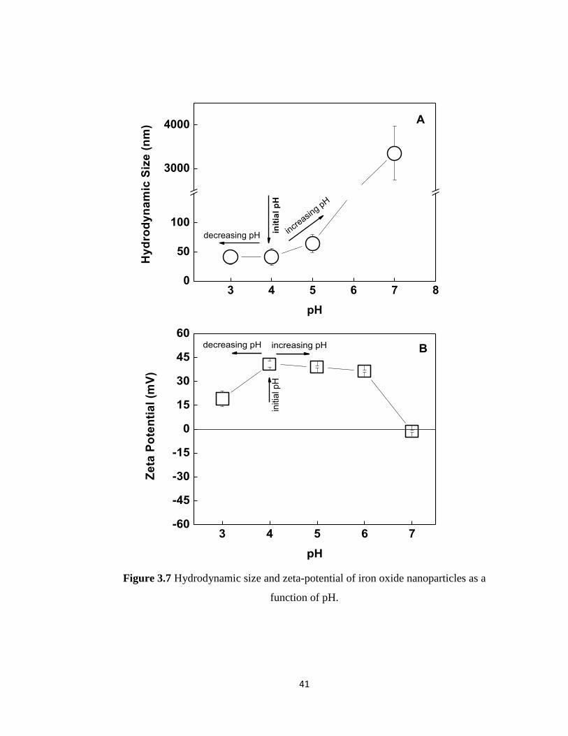
size and zeta-potential of the particles as a function of pH (Figure 3.7A and 3.7B). To
examine the pH-stability, two different samples were used. The pH of the solution
containing iron oxide nanoparticles was either increased above pH 4 or decreased below
pH 4. Note that the pH of the solution after synthesis was recorded to be ~ 4. As seen in
Figure 3.7A, hydrodynamic size increased above pH 4 and showed a sharp jump above
pH 5 indicating the aggregation of the particles and loss in aqueous solution stability.
Aggregation of the particles can be correlated with the decrease in zeta-potential of the
particles as the pH was increased. When the pH was gradually decreased below pH 4, a
decrease in the zeta-potential of the magnetite particles was also recorded. Although the
zeta-potential decreased down to +18.95±4.9 mV at pH 3, colloidal stability was not
affected. No significant change in hydrodynamic size was recorded at pH 3. Further
decreasing pH below 3 resulted in instantaneous precipitation of the particles. The

40
isoelectric point was determined to be at pH 6.8 by linear interpolation of the data. These
results suggest that the workable range with magnetite particles was between pH 3-4.
The results were observed were in agreement with the literature [161].
Figure 3.6 Evolution of number average hydrodynamic size of iron oxide nanoparticles
as a function of time.
0 2 4 6 8 10 12 14 16 18 20 22 240
20
40
60
80
Nu
mb
er
Av
era
ge
Hy
dro
dy
na
mic
Siz
e (
nm
)
Time (hours)
41
Figure 3.7 Hydrodynamic size and zeta-potential of iron oxide nanoparticles as a
function of pH.
3 4 5 6 7 80
50
100
3000
4000
decreasing pH
Hy
dro
dy
na
mic
Siz
e (
nm
)
pH
init
ial
pH
incr
easing p
H
A
3 4 5 6 7-60
-45
-30
-15
0
15
30
45
60decreasing pH
Ze
ta P
ote
nti
al
(mV
)
pH
initia
l p
H
increasing pH B

42
3.2. Characterization of the multilayers:
3.2.1. Layer-by-Layer growth of the films:
As mentioned in Section 3.1.2, magnetite nanoparticles were stable in a very narrow pH
range. Therefore, multilayers were fabricated at pH 4 - the pH at which magnetite
particles showed the highest pH-stability in the long term - to avoid the precipitation of
the particles during film assembly process. PVCL and TA were chosen as the polymer
building blocks of the films. Multilayers were constructed in the following order: 1) TA;
2) PVCL; 3) TA; 4) Magnetite nanoparticles and this cycle was repeated until desired
number of layers were deposited at the surface. Figure 3.8 shows schematic
representation of the multilayer architecture. These 4 layers will be denoted as 1
tetralayer in the rest of the thesis.
Figure 3.8 Multilayer architecture.

43
PVCL is a neutral polymer and has hydrogen accepting carbonyl groups. TA is a
polyphenol with 25 hydroxyl groups per molecule which may act as hydrogen donors.
TA has a pKa of 8.5. At the deposition pH of 4, TA has most of its hydroxyl groups in
the protonated form. Therefore, the driving force for deposition of PVCL onto TA layer
is hydrogen bonding interactions. In contrast, the driving force for the deposition of
positively charged magnetite particles onto TA layer is electrostatic interactions. Note
that ionization of TA is enhanced even at pH 4 when exposed to positively charged iron
oxide nanoparticle solution, resulting in an increase in the number phenolate ions.
Enhanced ionization of polyacids in the presence of salt cations [162] and/or polycations
[98] has been reported earlier.
Film growth was followed using UV-Vis Spectroscopy. Multilayers were constructed on
quartz slides and the change in intensity of the peak centered at 220 nm was followed as
a function of number of TA layers. Note that pure TA solution exhibits 2 peaks centered
at 219 nm and 276 nm in its neutral form (Figure 3.9A inset) [163]. As seen in Figure
3.9A, the intensity of the peak at 220 nm was increased with increasing number of TA
layers, indicating successful growth of the film. When the intensity of the peak at 220
nm is plotted as a function of TA layer number, a linear growth profile is obtained for
the multilayers (Figure 3.9B). In contrast to TA, PVCL and iron oxide nanoparticles do
not show absorbance in the UV-Vis region. However, the absorbance of the multilayer
films progressively increased between 300 nm and 600 nm with increasing number of
layers, indicating the successful growth of the film.

44
Figure 3.9 UV-vis spectrum of multilayers after TA deposition after every tetralayer
(Panel A). Intensity of the peak centered at 220 nm vs number of TA layers after every
tetralayer (Panel B).
200 300 400 500 600 700 800
0.0
0.5
1.0
1.5
2.0
2.5
200 300 400 500 600 700 800
0
1
2
3
4
5
Ab
so
rba
nc
e
Wavelength (nm)
Pure TA in aqueous solution
at pH 4
1
Ab
so
rba
nc
e
Wavelength (nm)
2
3
4
A
1 2 3 4
0.0
0.5
1.0
1.5
2.0
2.5
3.0
Ab
so
rba
nc
e a
t 2
20
nm
Number of TA layers
B

45
Multilayer growth was also confirmed by thickness measurements using AFM. Figure
3.10 shows evolution of film thickness obtained via AFM with increasing number of
tetralayers. Different from the data obtained via UV-Vis Spectroscopy, a deviation from
linearity was recorded at the end of 4th
tetralayer. This is probably due to significant
increase in surface roughness and enhanced aggregation of iron oxide nanoparticles at
higher number of layers, making film surfaces inhomogeneous and leads to unreliable
thickness measurements via AFM.
1 2 3 40
50
100
150
200
Th
ick
ness
(n
m)
Number of tetralayers
Figure 3.10 Evolution of film thickness with increasing number of tetralayers via atomic
force microscopy (AFM).
To further examine the change in morphology and surface roughness of the multilayers
with increasing number of tetralayers, topographical view of the multilayers were
obtained. Figure 3.11 shows AFM height images of the multilayers composed of 1, 2, 3
and 4 tetralayers. As visually observed in the images, surface roughness increases with

46
increasing number of layers. Figure 3.11E shows the change in roughness values with
increasing number of layers. The increase in surface roughness can be explained by
higher interpenetration of the layers as moving away from the substrate. Increase in
surface roughness also resulted in enhanced aggregation of iron oxide nanoparticles at
the surface. The aggregation as well as the increment in the number of iron oxide
nanoparticles were remarkable at higher number of layers which was evident by the
clusters of iron oxide nanoparticles observed in the images (Figure 3.11D). In addition to
increasing surface roughness, another reason behind the aggregation of the iron oxide
nanoparticles at the surface is the enhanced attraction among the iron oxide
nanoparticles due to the dipolar attractions as the amount of iron oxide nanoparticles
increase within the multilayers with increasing number of tetralayers. Decher et al. [139]
also showed that aggregation of the magnetic nanoparticles and surface roughness
increase with increasing number of layers in case of electrostatic multilayers of
polyallylamine hydrochloride (PAH) and polystyrene sulfonate (PSS) containing iron
oxide nanoparticles.

47
Figure 3.11 Atomic force microscopy images of 1 tetralayer (Panel A); 2 tetralayers
(Panel B); 3 tetralayers (Panel C); 4 tetralayers (Panel D) of multilayers of TA, PVCL
and iron oxide nanoparticles. Panel E shows evolution of surface roughness with
increasing number of layers.
A B
DC

48
Figure 3.11 Continued.
3.2.2. Characterization of magnetic properties of the multilayers:
Magnetic force microscopy measurements were carried out to prove the magnetic
properties of the iron oxide nanoparticles within the multilayer films. Magnetic force
microscopic measurements were performed using a special tip which was magnetized
prior to measurements to provide interaction with the magnetic field of the multilayer
films. At each measurement, scan line was consisted of 2 passes, i.e. trace and re-trace.
In the first scan, the topographical image was obtained in the tapping mode (tracing and
re-tracing the surface topography). Then, the tip is raised up to a certain distance (~ 16
nm) and a second pass (trace/re-trace cycle) was carried out. The lift mode minimized
the influence of surface topography and allowed measuring magnetic interactions. In
1 2 3 40
5
10
15
20
25
30
Ro
ug
hn
es
s (
nm
)
Number of Tetralayers
E
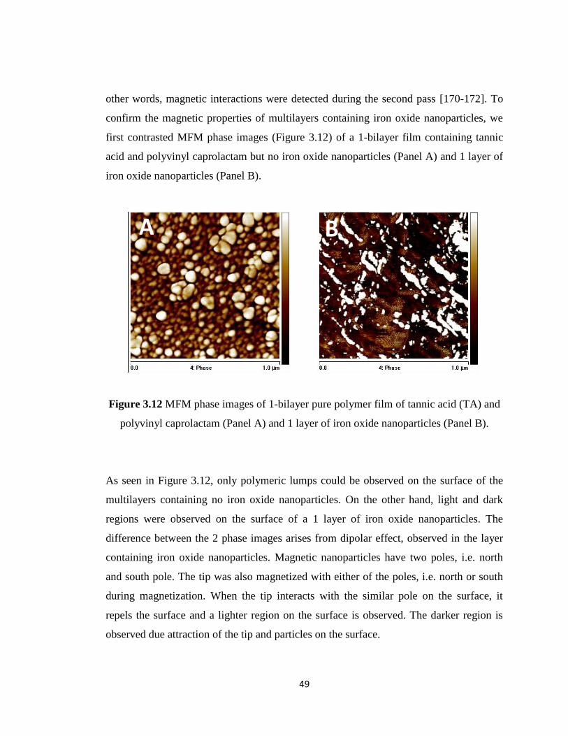
49
other words, magnetic interactions were detected during the second pass [170-172]. To
confirm the magnetic properties of multilayers containing iron oxide nanoparticles, we
first contrasted MFM phase images (Figure 3.12) of a 1-bilayer film containing tannic
acid and polyvinyl caprolactam but no iron oxide nanoparticles (Panel A) and 1 layer of
iron oxide nanoparticles (Panel B).
Figure 3.12 MFM phase images of 1-bilayer pure polymer film of tannic acid (TA) and
polyvinyl caprolactam (Panel A) and 1 layer of iron oxide nanoparticles (Panel B).
As seen in Figure 3.12, only polymeric lumps could be observed on the surface of the
multilayers containing no iron oxide nanoparticles. On the other hand, light and dark
regions were observed on the surface of a 1 layer of iron oxide nanoparticles. The
difference between the 2 phase images arises from dipolar effect, observed in the layer
containing iron oxide nanoparticles. Magnetic nanoparticles have two poles, i.e. north
and south pole. The tip was also magnetized with either of the poles, i.e. north or south
during magnetization. When the tip interacts with the similar pole on the surface, it
repels the surface and a lighter region on the surface is observed. The darker region is
observed due attraction of the tip and particles on the surface.
A B

50
Figure 3.13 shows the phase images of 1-, 2-, 3- and 4- tetralayer films. In Figure 3.13A,
the film contained only 1 layer of iron oxide nanoparticles and the dipolar effect of the
magnetic iron oxide nanoparticles can be clearly observed by the contrast of the light
and dark regions. However, further depositing tetralayers at the surface resulted in a
significant increase in the amount of lighter regions (Figure 3.13D) and the contrast of
the lighter and darker regions could no longer be observed. Couple of suggestions can be
made for this phenomenon:
1) Alignment of the iron oxide nanoparticles is affected by the alignment of the
previously deposited iron oxide nanoparticles which would induce the appearance of
either the lighter or darker regions at the surface. For example, if the number of iron
oxide nanoparticles facing the tip with a similar pole is higher in number than that facing
the tip with an opposite pole, then the formation of lighter regions on the surface will be
induced. This is the case observed in Figure 3.13D. However, the opposite case might
also be possible resulting in formation of darker regions. Both cases would result in an
increase in the contrast of dark and light regions.
2) The tip used during MFM measurements is capable of interacting with the iron oxide
nanoparticles which are maximum 100 nm beneath the top of the film. This means that
the interaction of the tip with the topmost iron oxide nanoparticles might be affected by
the iron oxide nanoparticles which were deposited previously into the multilayers. The
tip interacts with higher number of iron oxide particles as the number of tetralayers at
the surface increases. If the total number of iron oxide nanoparticles which interacts with
the tip with a similar pole is greater than that which interacts with the tip with an
opposite mole, the enhanced repulsion among the nanoparticles and the tip would result
in formation of larger amount of lighter regions.
3) The increase in surface roughness with increasing number of tetralayers resulted in
deposition of higher amount of iron oxide nanoparticles at the surface. However, higher
number of iron oxide nanoparticles at a particular layer might have induced aggregation

51
of the iron oxide nanoparticles at the surface through the lateral position due to stronger
dipolar effect as the distance between the iron oxide nanoparticles gets shorter. This
enhanced dipolar affect among the aggregated nanoparticles could be another reason of
the repulsion between the tip and the iron oxide nanoparticles resulting in an increase in
the lighter domains.
In conclusion, MFM images fortify the presence of higher amount of iron oxide
nanoparticles at the surface as the number of layers of iron oxide nanoparticles increase.
However, no matter how the iron oxide nanoparticles align within the multilayers, the
contrast of the light and dark regions will be lost with increasing number of iron oxide
layers. Therefore, MFM may not be a proper technique to characterize magnetic
properties of the multilayer films with more than one layer of iron oxide nanoparticles.
Further analysis of the multilayers will be performed using MFM to scrutinize the
convenience of the technique for characterization of magnetic properties of ultra-thin
polymer multilayer films containing more than one iron oxide layers.

52
Figure 3.13 MFM images of 1tetralayer-(Panel A); 2tetralayer- (Panel B); 3tetralayer-
(Panel C) and 4tetralayer- (Panel D) films.
3.2.3. pH stability:
pH stability of the multilayers was determined by immersing the multilayers into buffer
solutions at different pH values for 30 minutes and then tracking the amount of material
remained at the surface using UV-vis Spectroscopy. As mentioned in the experimental
section, the multilayers were prepared at pH 4.0. pH stability was evaluated by
A B
C D

53
immersing the films to either lower or higher pH values. Figure 3.14A shows the change
in intensity of the peak centered at 220 nm as the acidity increased. Almost no change in
peak intensity was recorded indicating the stability of the multilayers. Similarly, no
significant change in the intensity of the peak was recorded when the pH was gradually
increased from pH 4 to pH 9 (Figure 3.14B). To further understand the effect of iron
oxide nanoparticles on the pH-stability of the multilayers, pH-stability of pure PVCL
and TA multilayers which was constructed at pH 4 was also examined. Filled squares (in
Figure 3.14B) show the change in the normalized absorbance at 220 nm for PVCL/TA
layers (in the absence of iron oxide nanoparticles). As seen in Figure 3.14B,
incorporation of iron oxide nanoparticles within the multilayers did not cause a
significant change in the pH-stability of the multilayers. Therefore, it can be concluded
that the stability of the multilayers against pH was mostly due to nature of the
association among the polymer building blocks.

54
Figure 3.14 pH stability of multilayers of TA/PVCL/TA/iron nanoparticles at
decreasing (Panel A) and increasing (Panel B) pH values. Filled squares show the pH-
stability of pure polymer multilayers (TA/PVCL constructed at pH 4) as the acidity was
decreased and is plotted for comparison.
2.0 2.5 3.0 3.5 4.00.0
0.2
0.4
0.6
0.8
1.0
A
No
rm
ali
zed
Ab
sorb
an
ce a
t 2
20
nm
pH
decreasing pH
4 5 6 7 8 90.0
0.2
0.4
0.6
0.8
1.0
1.2
TA/PVCL/TA/iron oxide nanoparticles
TA/PVCL (nýo iron oxide particles)
No
rm
ali
zed
Ab
sorb
an
ce a
t 2
20
nm
pH
B
increasing pH

55
The stability of the multilayers has also been checked by following the change in the
UV-visible spectra of multilayers between 300 and 600 nm at different pH values.
Remember that the peak centered at 220 nm belongs to TA. Neither PVCL nor iron
oxide nanoparticles has a peak between 200 nm and 800 nm. However, the absorbance
of the multilayer films progressively increased between 300 nm and 600 nm as the
number of iron oxide nanoparticle layers increased within the multilayers. Therefore,
contrasting the UV-Visible spectra of the multilayers at different pH values could
provide information about the retention of iron oxide nanoparticles at the surface. Figure
3.15 shows the UV-Visible spectrum of the multilayers at pH 4, pH 6, and pH 9. As seen
in Figure 3.15, no significant change in the UV-Visible spectra of multilayers were
recorded, indicating also the retention of iron oxide nanoparticles within the multilayers.
200 300 400 500 600 700 800
0.0
0.5
1.0
1.5
2.0
2.5
3.0
Ab
so
rba
nce
Wavelength (nm)
pH 4
pH 6
pH 9
Figure 3.15 UV-Vis spectra of multilayers at pH 4, pH 6 and pH 9.

56
Changes in morphology of the multilayers with decreasing or increasing pH have also
been examined using AFM. AFM images (figure 3.16) show that roughness of the films
did not show a significant change when the multilayers were exposed to pH 2. In
contrast, when the multilayers were exposed to pH 7.5 for 30 minutes, films became
rougher due to increased ionization of TA resulting in partial disruption of the hydrogen
bonds among PVCL and TA molecules and loosening of the film structure.
Figure 3.16 AFM images of 4 tetralayers of TA/PVCL/TA/iron oxide nanoparticles
after exposure to pH 2 and pH 7.5 for 30 minutes. AFM image of the multilayers which
were constructed at pH 4 was plotted for comparison.
Multilayers of TA/PVCL/TA/iron oxide nanoparticles have also been examined using
MFM (Figure 3.17). As seen in the MFM images, we did not observe a significant
difference in MFM images of the films at pH 4 and pH 2. In contrast, we have a
decrease in the amount of lighter regions. This could be due to loosening of the
multilayer structure with increasing pH which might have resulted in a decrease in the
interaction among the iron oxide nanoparticles.
pH 4pH 2 pH 7.5
Ra = 15 nm Ra = 15.2 nm Ra = 15.2 nm Ra = 28.9 nm

57
Figure 3.17 MFM images of 4 tetralayers of TA/PVCL/TA/iron oxide nanoparticles
after exposure to pH 2 and pH 7.5 for 30 minutes. MFM image of the multilayers which
were constructed at pH 4 was plotted for comparison.
3.3. Controlled release of ciprofloxacin from multilayers:
In this part of the study, potential of multilayers were examined for their controlled
release properties at physiologically related pH values and temperature.
CIPRO was loaded into the multilayers during film preparation process (Figure 3.18).
CIPRO has a two pKavalues, the first one is 6.43 [167, 168, 169] and the second is 8.68
[167, 168, 169]. At the multilayer deposition pH of 4, CIPRO is positively charged,
whereas TA is partially negatively charged. Thus, CIPRO and TA can interact with each
other through electrostatic interactions. Complexes of CIPRO and TA were prepared in
aqueous solution by simply mixing the CIPRO and TA solutions at certain molar ratios
(details are given in experimental section). Then, multilayers were constructed by
immersing the substrate into solutions following the order of (CIPRO+TA)
complexes/PVCL/(CIPRO+TA) complexes/iron oxide nanoparticles. For release
experiments, 15 tetralayer films were constructed on both sides of the glass slides.
pH 4 pH 7.5pH 2

58
Release experiments were followed at 2 different pH and temperature values, i.e. pH 7.5
at 25°C and 37°Cand pH 8.5 at 25°C and 37°C.
Figure 3.18 Architecture of ciprofloxacin loaded multilayers.
Prior to releasing CIPRO from the multilayers, aqueous solution of CIPRO was
examined using UV-Vis Spectroscopy. To make sure that the peak centered at 270 nm
belonged only to CIPRO, UV-Visible spectra of CIPRO and TA were contrasted at pH
7.5 and pH 8.5. As seen in Figure 3.19, CIPRO in aqueous solution has a peak centered
at 270 nm and this peak does not overlap with any of the peaks of TA. Thus, for release
experiments, the change in the intensity of the peak at 270 nm was monitored as a
function of time. Figure 3.20 shows the normalized intensity of the peak centered at 270
nm as a function of time at pH 7.5 and pH 8.5 at 37°C.Note that once the release at pH

59
7.5 was complete, multilayers were immersed to pH 8.5 buffer solutions at the same
temperature. As seen in Figure 3.20, multilayers release around half of the amount of
CIPRO at pH 7.5. The reason is: 1) At pH 7.5, CIPRO is electrically neutral (first pKa of
CIPRO is 6.43) [167, 168, 169]. Thus, it loses its electrostatic interactions with TA and
releases from the multilayers. At pH 8.5, CIPRO carries more negative charge and its
release from the multilayers should be facilitated due to electrostatic repulsion between
negatively charged TA and negatively charged CIPRO. Also, at neutral and basic
conditions the binding strength among the layers are weakened due to ionization of TA
and loss in hydrogen bonding interactions among PVCL and TA. As also observed in
AFM images (Figure 3.16) in Section 3.2.3, multilayers go into morphological changes
after exposure to neutral pH conditions resulting in rough and loosened multilayer
structure. The morphological changes observed within the multilayer structure provides
a pathway and facilitates the release of CIPRO from the multilayers. One more
parameter which might have affected the release of CIPRO is the formation of voids
within the multilayers at 38-40 °C due to the phase separation of PVCL above its LCST.
Such a structure could have facilitated the release of CIPRO molecules from the
multilayers. Note that Sukhushvili and co-workers [174] and Erel et al [175] have earlier
reported on the enhanced release of functional molecules above the LCST of the
hydrogen accepting polymer component of the multilayers.

60
Figure 3.19 UV-Visible spectra of aqueous solutions of ciprofloxacin and TA at pH 7.5
(Panel A) and pH 8.5 (Panel B).
200 300 400 500 600 700 800
0.0
0.2
0.4
0.6
0.8
1.0
1.2
aqueous solution of CIPRO at pH 7.5
aqueous solution of TA at pH 7.5
Ab
sorb
an
ce
Wavelength (nm)
A
200 300 400 500 600 700 800
0.0
0.2
0.4
0.6
0.8
1.0
1.2
aqueous solution of CIPRO at pH 8.5
aqueous solution of TA at pH 8.5
Ab
sorb
an
ce
Wavelength (nm)
B

61
Figure 3.20 Release of ciprofloxacin from multilayers at pH 7.5 and pH 8.5 at
approximately 37˚C.
0 100 200 300 400 500 600 700
0.0
0.2
0.4
0.6
0.8
1.0
pH 7.5
No
rm
ali
zed
Ab
sorb
an
ce a
t 2
70
nm
Time (min)
pH 8.537°C

62

63
CHAPTER 4
CONCLUSION AND OUTLOOK
Iron oxide nanoparticles with an average particle size of 9 nm (based on TEM imaging)
were synthesized through ultrasound based co-precipitation. These iron oxide
nanoparticles were successfully incorporated into temperature-responsive hydrogen-
bonded polymer multilayers of PVCL and TA. Multilayers of PVCL, TA and iron oxide
nanoparticles have been successfully constructed at pH 4 through hydrogen bonding
interactions among PVCL and TA as well as electrostatic interactions among TA and
iron oxide nanoparticles. Multilayers were highly stable at neutral and basic pH
conditions. Magnetic properties of the multilayers were confirmed using MFM. It was
also found that an antibiotic which is used for the treatment of different bacterial
infections in the body, ciprofloxacin, can be successfully incorporated into the
multilayers during film assembly and released from the multilayers simply by a pH
trigger.
The work presented in this thesis can form a basis for the development of more
advanced polymer platforms for bio-imaging and controlled release of functional
molecules from surfaces. This study is also important for gathering a temperature-
responsive polymer and iron oxide nanoparticles in the same polymer LbL film matrix.
Therefore, these multilayers can be promising materials for future application as
platforms for magnetothermally triggered release of functional molecules from surfaces.

64
The future work on this study will consist of the following parts:
1) Multilayers will be examined for magnetothermal trigger of drug molecules from the
surface by applying AC magnetic field. An increase in temperature is expected to be
induced within the multilayers after exposure to AC magnetic field followed by heating
of iron oxide nanoparticles. Increase in temperature will probably induce conformational
changes in the PVCL chains above the LCST. Such a conformational change in PVCL
chain will probably result in formation of voids within the multilayers and release of
drug molecules.
2) The multilayers presented in this thesis are capable of releasing the drug molecules at
neutral and basic conditions, while retaining the iron oxide nanoparticles within
themselves. It is also of interest to design multilayers which release both drug molecules
and iron oxide nanoparticles simultaneously. Hydrogen-bonded multilayers which are
capable of releasing both drug molecules and iron oxide nanoparticles will be designed.

65
REFERENCES
[1] C. Ankerfors, Polyelectrolyte Complexes: Their preparation, adsorption behavior,
and effect on paper properties, Licentiate Thesis, Royal Institute of Technology, 2008.
[2] S. L. Dakhara, C. C. Anajwala, Syst. Rev. Pharm., 2010, 1, 121-7.
[3] D. V. Pergushov, A. H. E. Muler, F. H. Schacher, Chem. Soc. Rev., 2012¸41, 6888-
6901.
[4] V. V. Khutoryanskiy, International Journal of Pharmaceuticals, 2007, 334, 15-26.
[5] S. Lankalopalli, V. R. N. Kolapalli, Indian J. Pharm. Sci., 2009, 71, 5, 481-487.
[6] R. M Fuoss, H. Sadek, Science, 1949, 110, 552-554.
[7] A. S. Michaels, R. G. Miekka, J. Phys. Chem., 1961, 1765-1773.
[8] E. Tsuchida, K. Abe, Advances in Polymer Science, Springer-Verlag, Berlin
Heidelberg, Germany, 1982, 45, 1-130.
[9] V. Kabanov, Multilayer Thin Films, 2003, Wiley-SCH Verlag GmbH, Weiheim,
Germany, 47-86.
[10] V. A. Kabanov, A. B. Zenzin, Pure Appl. Chem., 1984, 56, 3, 343-354.
[11] M Senuma, S. Kuwabara, K. Kaeriyama, F. Hase, Y. Shimira, J. Appl. Polym. Sci.,
1986, 31, 1687-97.
[12] Y. Hirouki, K. Takeshi, Chem. Eng. Japan, 1989, 41, B11-5.
[13] J. G. Atkinson, Biochem. Biophys. Acta., 1973, 308, 41-52.
[14] Q. Zhao, Q. F. Sn, Y. Ji, J. Qian, C. Gao, J. Membr. Sci., 2011, 379, 19-45.

66
[15] H. Dautzenberg, J. Kotz, K. J. Linow, B. Phillipp, G. Rother, Macromolecular
complexes in chemistry and biology, Berlin, Springer Verlag, 1994, 119-33.
[16] P. Bertrand, A. Jonas, A. Laschewsky, R. Legras, Macromol. Rapid Commun.,2000,
21, 319–348.
[17] Z. Y. Tang, Y. Wang, P Podsiadlo, N. A.Kotov, Adv. Mater., 2006, 18, 3203–3224.
[18] R. K. Iler, J. Colloid and Interface Sci., 1966, 21,569-594.
[19] M. M. Viliers, D. P. Otto, S. J. Strydom, Y. M. Lvov, Advanced Drug Delivery
Reviews, 2011, 63, 701-715.
[20] Y. Jang, S. Park, K. Char, Korean J. Chem. Eng., 2011, 28, 1149-1160.
[21] F. M. Koehler, M. Fabian, M. Rossier, M.Waelle, E. K. Athanassiou, L.K.
Limbach, R. N. Grass, D. Gunther, W. J. Stark, Chem. Commun., 2008, 32, 4862-4865.
[22] J. B. Schlenoff, S. T. Dubas, T. Farhat, Langmuir, 2000, 16, 26, 9968-9969.
[23] A. Izquierdo, S. S. Ono, J. G. Voegel, P. Schaaf, G. Decher, Langmuir, 2005, 21,
16, 7558-7567.
[24] P. A. Chiarelli, M. S. Johal, D. J. Holmes, J. L. Casson, J. M. Robinson, H. L.
Wang, Langmuir, 2002, 18, 1, 168-173.
[25] P. Bertrand, A. Jonas, A. Laschewky, R. Legras, Macromol. Rapid Commun., 2000,
21, 319-348.
[26] Z. Y. Tang, Y. Wang, P. Podsiadlo, N. A. Kotov, Adv. Mater., 2006, 18, 3203-
3224.
[27] J. F. Quinn, A. P. R. Johnston, G. K. Such, A. N. Zeliktin, T. Caruso, Chem. Soc.
Rev., 2007, 36, 707-718.
[28] G. Decher, J. B. Scheloff, Multilayer Thin Films: Sequential Assembly of
Nanocomposites Materials, ed. Wiley-VCH Verlag & Co., Weinheim, Germany, 2012.

67
[29] G. Decher and J. Schmitt, Prog. Colloid Polym. Sci., 1992, 89, 160-164.
[30] D. Ingersoll, P. J. Kulesza, L. R. Faulkner, J. Electrochem. Soc., 1994, 141, 140-
147.
[31] S. Liu, D. Volkmer, D. G. Kurth, J. Cluster Sci., 2003, 14, 405-419.
[32] N. A. Kotov, I. Dekany, J. H. Fendler, J. Phys. Chem., 1995, 13, 13065-13069.
[33] M. M. Ling, K. Y. Wang, T. S. Chung, Ind. Eng. Chem. Res., 2010, 49, 5869-5876.
[34] A. A. Mamedov, N. A. Kotov, M. Prato, D. M. Guldi, J. P. Wicksted, A. Hirsch,
Nat. Mater., 2002, 1, 190-194.
[35] C. Jiang, H. Ko, V. V. Tsukruk, Adv. Mater., 2005, 17, 2127-2131.
[36] S. W. Keller, H. N. Kim, T. E. Mallouk, J. Am. Chem. Soc., 1994, 116, 8817.
[37] E. R. Kleinfeld, G. S. Ferguson, Science, 1994, 265-370.
[38] T. M. Cooper, A. L. Campell, R. L. Crane, Langmuir, 1995, 11, 2713-2718.
[39] T. A. He, R. Valluzi, K. Yang, T. Dolukhanyan, C. Sung, J. Kumar, S. K. Tripathy,
L. Samuelson, L. Balogh, D. A. Tomalia, Chem. Mater., 1999, 11, 3268.
[40] K. Araki, M. J. Wagner, M. S. Wrighton, Macromolecules, 1996, 16, 5392-5397.
[41] Y. Lvov, G. Decher, G. Sukhorukov, Macromolecules, 1993, 26, 5396.
[42] J. D. Hong, K. Lowack, J. Schmitt, G. Decher, Prog. Colloid Polym. Sci., 1993, 93,
98.
[43] Y. Lvov, K. Ariga, T. Kuhitake, Chem. Lett., 1994, 23, 23.
[44] Y. Lvov, K. Ariga, I. Ichinose, T. Kunitake, J. Am. Chem. Soc., 1995, 117, 6117-
6123.

68
[45] W. Kong, X. Zhang, M. L. Gao, H. Zhou, W. Li, J. C. Shen, Macromol. Rapid
Commun., 1994, 15, 405-409.
[46] P. J. Yoo, K. T. Nam, J. Qi, S. K. Lee, J. Park, A. M. Belcher, P. T. Hammond, Nat.
Mater., 2006, 5, 234.
[47] M. Michel, V. Toniazzo, D. Ruch, Y. Ball, ISRN Material Science, 2012.
[48] W. B. Stockton, M. F. Rubner, Macromolecules, 1997, 30, 2717.
[49] L. Y. Wang, Z. Q. Wang, X. Zhang, J. C. Shen, Macro. Mol. Rapid Commun.,
1997, 18, 509.
[50] S. A. Sukhishvili, S. Granick, Macromolecules, 2000, 122, 9550.
[51] S. A. Sukhishvili, S. Granick, Macromolecules, 2002, 35, 301.
[52] X. Zhang, J. C. Shen, Adv. Matter., 2006, 18, 1672.
[53] M. L. Gao, X. X. Kong, X. Zhang, J. C. Shen, Chem. J. Cin. Univ., 1993, 14, 1182.
[54] G. Decher, Science, 1997, 277, 1232.
[55] W. Kong, X. Zhang, M. L. Gao, H. Zhou, W. Li, J. C. Shen, Macromol. Rapid
Commun., 1994, 15, 405.
[56] H. Lee, L. J. Kepley, H. G. Hong, X. Zhang, J. Am. Chem. Soc., 1988, 110, 618.
[57] P. Kohli, G. J. Blanchard, Langmuir, 2000, 16, 4655.
[58] P. Kohli, K. K. Taylor, J. J. Harris, G. J. Blanchard, J. Am. Chem. Soc., 1998, 120,
11962.
[59] E. Chan, D. Lee, M. Ng, G. Nu, K. Lee, L. Yu, J. Am. Soc., 2002, 12438.
[60] I. Ichinose, H. Senzu, T. Kunitake, Chem. Mater., 1997, 9, 1296.
69
[61] S. Lee, I. Ichinose, T. Kunitake, Langmuir, 1998, 14, 2857.
[62] G. Acharya, T. Kunitake, Langmuir, 2003, 19, 2260.
[63] Q. Wang, H. Yu, L. Zhong, J. Liu, J. Q. Sun, J. C. Shen, Chem. Mater., 2006, 18,
1988.
[64] E. H. Kang, P. C. Jin, Y. Q. Yang, J. Q. Sun, J. C. Shen, Chem. Commun., 2006,
4332.
[65] W. Muler, H. Ringsdorf, E. Rump, G. Wildburg, X. Zhang, L. Angermaier, W.
Knoll, M. Liley, J. spinke, Science, 1993, 262, 1706.
[66] J. D. Hong, K. Lowack, J. Scmitt, G. Decher, Prog. Colloid. Polym. Sci., 1993, 93,
98.
[67] G. Decher, B. Lehr, K. Lowack, J. Schmitt, Biosens. Bioelectron., 1994, 9, 677.
[68] C. ourdillon, C. Demialle, J. Moiroux, J. M. Saveant, J. Am. Chem. Soc., 1994,
116, 10328.
[69] Y. Shimazaki, M. Mitsuishi, S. Ito, M. Yamamoto, Langmuir, 1997, 13, 1385.
[70] Y. Shimazaki, M. Mitsuishi, S. Ito, M. Yamamoto, Langmuir, 1998, 14, 1768.
[71] Y. Shimazaki, M. Mitsuishi, S. Ito, M. Yamamoto, Macromoleculer, 1999, 32,
8220.
[72] Y. Shimazaki, S. Ito, Langmuir, 2000, 16, 9478.
[73] L. Cheng, S. J. Dong, Electrochem. Commun., 1999, 1, 159.
[74] L. Cheng, S. J. Dong, J. Electroanal. Chem., 2000, 481, 168-176.
[75] D. Zhang, K. Zhang, Y. L. Yao, X. H. Xia, H. Y. Chen, Langmuir, 2004, 20, 7303.

70
[76] A. Zhuk, S. Pavlukhina, S. A. Sukhishvili, Langmuir, 2009, 25, 24, 14025-14029.
[77] Y. Zhu, J. Shi, W. Shen, X. Dong, J. Fong, M. ruan, Y. Li, Angew. Chem., 2005,
117, 5213-5217.
[78] Y. Yan, G. K. Such, A. P. R. Johnston, H. Lomas, F. Caruso, ACS Nano, 2011, 5,
4252-4257.
[79] M. Matsusaki, H. Ajiro, T. Kida, T. Serizawa, M. Akashi, Adv. Mater., 2012, 24,
454-474.
[80] Y. Li, X. Wang, J. Sun, Chem. Soc. Rev., 2012, 41, 5998-6009.
[81] J. A. Lichter, K. J. Van Vilet, M. F. Rubner, Macromolecules, 2009, 42, 8573-
8586.
[82] G. Decher, J. B. Scheloff, Multilayer Thin Films: Sequential Assembly of
Nanocomposites Materials, ed. Wiley-VCH Verlag & Co., Weinheim, Germany, 2012.
[83] Y. Lvov, F. Caruso, Anal. Chem., 2001, 73, 4212-4217.
[84] Y. Lvov, S. Yamada, T. Kunitake, Thin Solid Films, 1997, 300, 107-112.
[85] E. Kang, T. Bu, P. Jin, J. Sun, Y. Yang, J. Shen, Langmiur, 2007, 23, 7594-7601.
[86] G. M. Lowman, H. Tokuhisa, J. L. Lutkenhaus, P.T. Hammond, Langmiur, 2004,
20, 9791-9795.
[87] X. Sheng, L. Zhai, M. F. Rubner, R. E. Cohen, US Patent 8153233 B2, 2012,
Massachuetts Institute of Technology, Cambridge, MA (US).
[88] E. Kharlampieva, S. A. Shukhishvili, Langmuir, 2003, 19, 1235.
[89] E. Kharlampieva, S. A. Shukhishvili, Langmuir, 2004, 20, 10712.
[90] S. S. Ono, G. Decher, Nano. Lett., 2006, 6, 592-598.

71
[91] G. Ibraz, L. Dohne, E. Donath, H. Moehwald, Adv. Matter., 2001, 13, 1324.
[92] A. Fery, B. Scholer, T. Cassagneau, F. Caruso, Langmuir, 2001, 12, 3779-3783.
[93] V. Kozzlovskaya, E. Kharlampieva, M. L. Mansfield, S. A. Sukhishvili, Chem.
Mater., 2006, 18, 328-336.
[94] D. Delongchamp, P. Hammond, Langmuir, 2004, 20, 5403-5411.
[95] Z. Zhu, S. A. Sukhishvili, ACS Nano, 2009, 3, 11, 3595-3605.
[96] A. Zhuk, S. Pavlukhina, S. A. Shukhishvili, Langmuir, 2009, 25, 24, 14025-14029.
[97] Z. Zhu, N. Gao, H. Wang, S. A. Sukhishvili, Journal of Controlled Release, 2013,
171, 73-80.
[98] I. Erel-Unal, S. A. Shukhishvili, Macromolecules, 2008, 41, 3962-3970.
[99] E. Kharlampieva, V. Kozlovskaya, J. Tyutina, S. A. Shukhishvili, Macromolecules,
2005, 38, 10523-10531.
[100] W. Wang, L. Liu, X. J. Ju, D. Zerrouki, R. Xie, L. H. Yang, L. Y. Chu,
Chemphschem, 2009, 10, 2405-2409.
[101] S. H. Hu, C. H. Tsai, C. F. Liao, D. M. Liu, S. Y. Chen, Langmuir, 2008, 24,
11811-11818.
[102] J. L. Gilmore, X. Li, L. Quan, A. V. Kabanov, J. Neuroimmune Pharmacol.,2008,
Jan 22.
[103] T. J. Deerinck, Toxicol Pathol., 2008, 36, 1, 112-6.
[104] S. J. Son, X. Bai, S. B. Lee, Drug Discov. Today, 2007, 12, 15-16, 650-6.
[105] B.Issa, I. M. Obaidat, B. A. Albiss, Y. Haik, Int. J. Mol. Sci., 2013, 14, 21266-
21305.

72
[106] A. K. Gupta, M. Gupta, Biomaterials, 2005, 18, 3995-4021.
[107] A. Jordan et al., Journal of Magnetism and Magnetic Materials, 2001, 225, 118-
126.
[108] P. Neuberger et al., Journal of Magnetism and Magnetic Materials, 2005, 293, 1,
483-496.
[109] C. Von Zur Muhlen et al., Atherosclerosis, 2007, 193, 1, 102.
[110] Q. A. Pankhurst, K. Connolly, S. K. Jones, J. Dobson, J. Phys. D, 2003, 36, R167-
R181.
[111] J. P. Fortin, G. Gaxeau, C. Willhelm, Eur. Biophys., 2008, 37, 223-228.
[112] R. Hergt, S. Dutz, J. Magn. Magn. Mater., 2007, 311, 187-192.
[113] S. E. Barry, Int. J. Hyperth., 2008, 24, 451.
[114] B. Thiesen, A. Jordon, Int. J. Hyperth., 2008, 24, 467-474.
[115] C. C. Berry, A. S. Curtis, J. Phys. D, 2003, 36, R198-R206.
[116] P. Wust, U. Gneveckow, M. Johannsen, D. Bohner, T. Henkel, F. Kahman, J.
Schouli, R. Felix, A. Jordan, Int. J. Hyperth., 2006, 22, 673-685.
[117] N. A. Spaldin, Magnetism Materials: Fundamentals and Applications, 2nd
Edition,
Cambridge University Press.
[118] M. Ghesian, M. Mozaffari, M. Acet, J. Amighian, Journal of Magnetism and
Magnetic Materials, 2008, 320.
[119] R. M. Cornell, U. Schwertfeger, Wiley VCH, Weinheim, 2003.
[120] Pierro A. Dresco, Valdimir S. Zaitser, Richard J. Gambino, Benjamin Chu,
Langmiur, 1999, 15, 6.

73
[121] C. P. Bean, J. D. Livingston, Journal of Applied Physics, 1959, 30, 120-129.
[122] R. R. Baker, J. G. Mather, J. H. Kemnaugh, Nautre, 1983, 301, 79-80.
[123] R. Dronskowski, Adv. Funct. Mater., 2001, 11, 27.
[124] S. Santra, R. Tapec, N. Theodoropoulou, J. Dobson, S. Hebard, W.Tan, Langmiur,
2001, Vol. 17, No. 10, 2900-2906.
[125] D. Maity, D. C. Agarwal, Journal of Magnetism and Magnetic Materials, 308,
2007, 46-55.
[126] Ming Ming Ling, Kai Yu Wang, Tai Shung Chang, Ind. Eng. Chem. Res., 2010,
49, 5869-5876
[127] R. Massart, IEEE Trans. Magn., 1981, 17, 1247.
[128] R. M. Cornell, U. Schwertmann, Willey-Woch, ISBN 3-527-29669-7, Weinheim,
Germany, 2000, 55-60.
[129] Jorg Rockenberger, Erik C. Scher, A. Paul Alivisatos, Journal of American
Chemical Society, 1999, 121, 11595-111596.
[130] Lee et al, Journal of Biomedical Materials Research Part: B, Applied
Biomaterials, 79B, 2006, 142-150.
[131] Beniot P. Pichon, Pierrce Louet, Olivier Felix, Marc Drillon, Sylvie Begin-Colin,
Gero Decher, Chem. Mater., 2011, 23, 3668-3675.
[132] J. Park, K. AN, Y. Hwang, J. G. Park, H. J. Noh, J. Y. Kim, J. H. Park, N. M.
Hwang, T. Hyeon, Nat. Mat., 2004,3, 891-895.
[133] P. Tartaj, M. P. Morales, S. Veintemillas- Verdageur, T. Gonnzalez-Carreno, C. J.
Serna, Handbook of Magnetic Materials, 2006, 9, 403.

74
[134] A. Demotiere, P. Panissod, B. P. Pichon, G. Pourroy, D. Guillon, B. Donnio, S.
Begin-Colin, Nanoscale, 2011, 3, 226.
[135] S. F. Chin, S. C. Pang, C. H. Jan, J. Mater. Environ. Sci., 2011, 3, 299-302.
[136] A. Demortiere, B. Pichon, P. Panissod, B. Donnio, G. Pourroy, D. Gullion, S.
Begin-Colin, Nanaoscale, 2011, 255-302.
[137] B. P. Pichon, O. Gerber, C. Lefevre, I, Florea, S. Fleulot, W. Baaziz, M. Pauly, M.
Ohlmann, C. Ulhaq, O. Ersen, V. Pierron-Bohnes, P. Panissod, M. Drillon,, S. Begin-
Colin, Chem. Mater., 2011, 23, 2886-2900.
[138] B. P. Pichon, P. Leout, O. Felix, M. Drillon, S. Begin-Colin, G. Decher, Chem.
Mater., 2011, 23, 3668-3675.
[139] Y. Liu, A. Wang, R. O. Claus, Appl. Phys. Lett., 1997, 71, 16, 2265-2267.
[140] A. Demortiere, S. Buathong, B. P. Pichon, P. Panissod, D. Guillon, S. Begin-
Colin, B. Donnio, Small, 2010, 6, 1341.
[141] T. Fried, G. Shemer, G. Markovich, Adv. Mater., 2001, 13, 1158.
[142] F. Mammeri, Y. L. Bras, T. J. Daou, J. L. Gallani, S. Collins, G. Pourroy, B.
Donnio, D. Guillon, S. Begin-Colin, J. Phys. Chem. B, 2009, 113, 734.
[143] M.. Pauly, B. P. Pichon, A. Demortiere, J. Delahaye, C. Leuvrey, G. Pourroy, S.
Begin-Colin, Superlattices Mircostruct., 2009, 46, 195.
[144] M. Pauly, B. P. Pichon, P. A. Albouy, S. Fluetot, C. Leuvrey, M. Trassin, J. L.
Gallani, S. Begin-Colin, J. Mater. Chem., 2011, DOI: 10.1039/cljm12012c.
[145] X. Wang, S. Y. Zhou, Y. Lai, J. Q. Sun, J. C. Shen, J. Mater. Chem., 2010, 20,
555-560.

75
[146] F. Shi, S. H. Lui, H. T. Gao, N. Ding, L. J. Dong, W. Tremel, W. Knoll, Adv.
Mater., 2009, 21, 1927-1930.
[147] G. J. Wang, Y. N. Fang, P. Kim, A. Hayek, M. R. Weatherspoon, J. W. Perry, K.
H. Sandhage, S. R. Marder, S. C. Jones, Adv. Func. Mater., 2009, 19, 2768-2776.
[148] L. H. Zhang, Y. M. Zhai, N. Gao, D. Wen, S. Dong, J. Electrochem. Commun.,
2008, 10, 1524-1526.
[149] F. Hua, T. Cui, Y. M. Lvov, Nano Lett., 2004, 4, 823.
[150] W. Xue, T. Cui, J. Nanosci. Nanotechnol., 2007, 7, 2647.
[151] L. Yanying, W. Anbo, O. C. Richard, Appl. Phys. Lett., 1997, 2265-2267.
[152] M. Mazur, A. Barras, V. Kuncser, A. Galatanu, V. Zaitev, K. V. Turchemiuk, P.
Woisel, J. Lyskawa, W. Laure, A. Siriwardena, R. Boukherroub, S. Szunerits,
Nanoscale, 2013, 5, 2692-2702.
[153] B. P. H. Do, B. D. Nguyen, H. D. Nguyen, P. T. Nguyen, Adv. Nat. Sci.: Nanosci.
Nanotechnology, 2013, 4, 045016.
[154] M. Shen, H. Cai, X. Wang, X. Cao, K. li, S. H. Wang, R. Guo, L. Zheng, G.
Zhang, X. Shi, Nanotechnology, 2012, 23, 105601.
[155] X. Huang, A. Schmuker, J. Dyke, S. M. Hall, J. Retrum, B. Stein, N. Remmes, D.
V. Baxter, B. Gragnea, L. M. Bronstein, J. Mater. Chem., 2009, 19, 4231-4239.
[156] A. Khan, Material Letters, 2008, 62, 898-902.
[157] S. Mahadevan, G. Gnanaprakash, J. Philip, B. P. C. Rao, T. Jayakumar, Physica E,
2007, 39, 20-25.
[158] H. Qu, D. Caruntu, H. Liu, C. J. O‟Connor, Langmuir, 2011, 27, 2271- 2278.

76
[159] B. Tural, N. Ozkan, M. Volkan, J. of Phys. And Chem. of solids, 2009, 70, 860-
866.
[160] M. Mazur, A. Barras, V. kuncser, A. Galatanu, V. Zaitzev, K. V. Turcjeniuk, P.
Woisel, J. Lyskawa, W. Laure, A. Siriwardena, R. Boukherroub, S. Szunerits,
Nanoscale, 2013, 5, 2692-2702.
[161] M. Baalousha, Science of the total environment, 2009, 407, 2093-2101.
[162] I. Erel-Unal, S. A. Sukhishvili, Macromolecules, 2008, 41, 11, 8737-8744.
[163] M. G. Albu, M. V. Gluca, M. Gillgrinca, V. Trandafir, L. Popa, C. Cotrut, Rev.
Chim., 2009, 60, Nr. 7, 666-672.
[164] H. Gu, K. Zu, Z. Yang, C. K. Chang, B. Xu, Chem. Commun., 2005, 4270-4272.
[165] L. Wang, J. Luo, M. M. Maye, Q. Fan, Q. Rendeng, M. H. Engelhard, C. Wang,
Y. Lin, C. J. Zhong, J. Mater. Chem., 2005, 15, 1821-1832.
[166] Y. Maeeda, Langmiur, 2001, 17, 1737.
[167] G. Volgyi, R. Ruiz, K. Box, J. Corner, E. Bosch, K. T. Novak, Anal. Chim. Acta,
2007, 583, 418.
[168] SPARC V3.1, http://ibmlc2.chem.uga.edu/sparc/
[169] J. Barbosa, R. Berges, I. Toro, V. S. Nebot, Talanta, 1997, 44, 1271.
[170]S. Schreiber, M. Savla, D.V. Pelekhov, P. C. Hammel, G. Agarwal, Small, 2008, 4,
No. 2, 270-278.
[171] J. Wotshadlo, T. Liebert, J. H. Clement, N. Anspach, S. Hoppener, T. Rudolph, R.
Muller, F. H. Schacher, U. S. Schubert, T. Heinze, Macromol. Biosci., 2013, 13, 93-105.

77
[172] C. S. Neves, P. Quaresma, P. V. Baptista, P. A. Carvalho, J. P. Araujo, E. Pereira,
P. Eaton, Nanotechnology, 2010, 21, 305706.
[173] S. A. Sukhishvili, S. Granick, Macromolecules, 2002, 35, 1, 301-310.
[174] E. Kharlampieva, V. Kozlovskaya, J. Tyutina, S. A. Sukhishvili, Macromolecules,
2005, 38, 25, 10523-10531.
[175] I. Erel, H. E. Karahan, C. Tuncer, V. Butun, A. L. Demirel, Soft Matter,2012, 8,
827-836.