preliminary geotechnical engineering report · pdf file1 preliminary geotechnical engineering...
TRANSCRIPT

1
Preliminary Geotechnical Engineering Report
Constant Avenue Reconstruction Irving Hill Road to 19th Street
Lawrence, KS
March 5, 2012 Terracon Project No. 02125035.001
Prepared for:
SK Design Group, Inc. Overland Park, KS
Prepared by:
Terracon Consultants, Inc. Lenexa, KS

TABLE OF CONTENTS
Page
1.0 INTRODUCTION ..................................................................................................... 1
2.0 PROJECT INFORMATION ..................................................................................... 1
3.0 SUBSURFACE CONDITIONS ................................................................................ 2
3.1 Soil and Bedrock Conditions ....................................................................... 2
3.2 Groundwater Observations ......................................................................... 3
4.0 PRELIMINARY ENGINEERING RECOMMENDAITONS ....................................... 3
4.1 Geotechnical Considerations....................................................................... 3
4.2 Subgrade Preparation ................................................................................. 4
4.3 Engineered Fill ............................................................................................ 4
4.4 Preliminary Opinions of Pavement Thickness ............................................. 5
4.4.1 Choice of Pavement Material ........................................................... 5
4.4.2 Pavement Surface Drainage............................................................ 6
4.4.3 Pavement Subsurface Drainage ...................................................... 6
4.4.4 Pavement Maintenance ................................................................... 7
4.5 Construction Considerations ....................................................................... 8
5.0 GENERAL COMMENTS ......................................................................................... 8
APPENDIX A – FIELD EXPLORATION Exhibits A-1 Boring Location Diagram Exhibits A-2 to A-14 Boring Logs Exhibit A-15 Field Exploration Description
APPENDIX B – LABORATORY TESTS
Exhibit B-1 Laboratory Tests APPENDIX C – SUPPORTING DOCUMENTS
Exhibit C-1 General Notes Exhibit C-2 Unified Soil Classification System Exhibit C-3 General Notes – Description of Rock Properties

March 5, 2012 SK Design Group, Inc. 4600 College Boulevard, Suite 100 Overland Park, KS 66211 Attn: Mr. Sassan Mahobian, P.E., LEED AP Re: Preliminary Geotechnical Engineering Report
Constant Avenue Reconstruction Irving Hill Road to 19th Street Lawrence, KS Terracon No. 02125035.001
Dear Mr. Mahobian: Terracon Consultants, Inc. (Terracon) has completed the subsurface exploration and laboratory tests described in our Agreement for Services dated February 3, 2012. This Preliminary Geotechnical Engineering Report presents the boring logs with test data and provides preliminary geotechnical recommendations and/or opinions concerning earthwork along the alignment and minimum pavement thickness. Terracon will prepare the Final Geotechnical Engineering Report following Consultation with SK Design. We appreciate the opportunity to be of service to SK Design Group on this project. If you have any questions regarding this report, please contact us. Sincerely,
Terracon Consultants, Inc. Craig K. Denny, Ph.D., P.E. Senior Consultant Kansas: 10043
Steven M. Levorson, Ph.D., P.E. Senior Consultant
Enclosures Report Distribution: Addressee (1) File (1)
Terracon Consultants, Inc. 13910 W 96th Terrace Lenexa, Kansas 66215 P [913] 492 7777 F [913] 492 7443 terracon.com
Responsive ■ Resourceful ■ Reliable 1
PRELIMINARY GEOTECHNICAL ENGINEERING REPORT
CONSTANT AVENUE RECONSTRUCTION IRVINING HILL ROAD TO 19TH STREET
LAWRENCE, KANSAS
Project No. 02125035 March 5, 2012
1.0 INTRODUCTION The University of Kansas retained SK Design Group, Inc. (SK Design) to provide Professional Engineering Services for the Constant Avenue Reconstruction project from Irving Hill Road to 19th Street. The project includes the following alignment components:
Constant Avenue from the south side of the intersection at Irving Hill Road to 19th Street, including the 19th Street intersection
The Irving Hill Road and Constant Avenue Intersection Irving Hill Road from the west side of the bridge over Iowa Street to the east side of the
Irving Hill Road and Constant Avenue intersection 19th Street from Constant Avenue to the west side of the intersection at Iowa Street
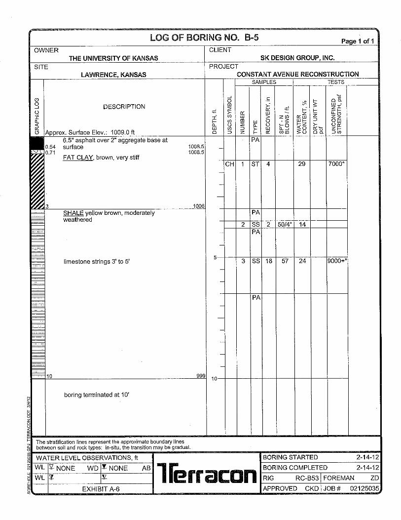
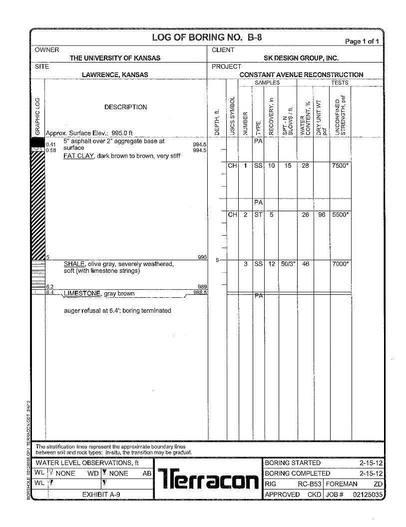
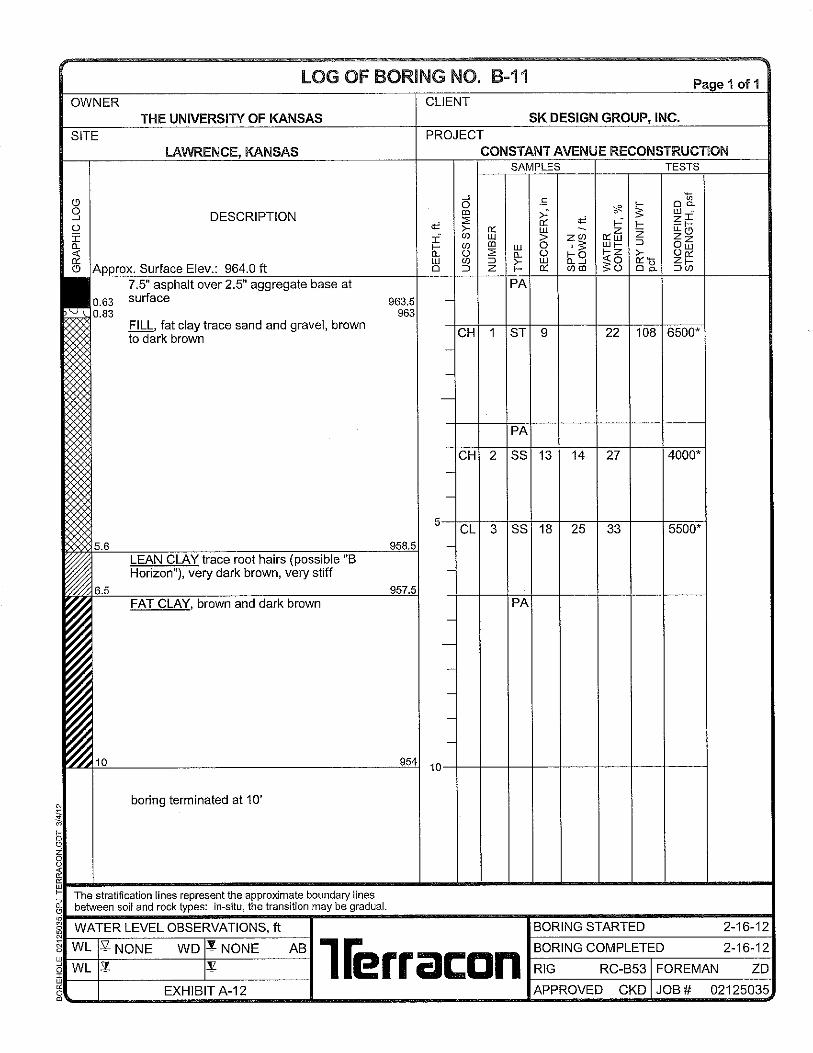
SK Design retained Terracon Consultants, Inc. (Terracon) to provide Professional Geotechnical Engineering Services. Terracon performed exploratory borings at 13 locations along the above described alignment sections. Borings extended to depths ranging from 2.5 feet to 10 feet below the existing pavement surface. Logs of the borings with laboratory test data and a boring location diagram are included in Appendix A of this report. The purpose of this Preliminary Geotechnical Engineering Report is to present the data and provide preliminary geotechnical engineering opinions and/or recommendations to be incorporated in the design plans and specifications for this reconstruction project. Terracon will prepare the Final Geotechnical Engineering Report following consultation with SK Design.
2.0 PROJECT INFORMATION The project is located on the West Campus of The University of Kansas (KU). Prior to retaining SK Design to provide Professional Engineering Services, KU provided the following initial guidance concerning pavement sections:
Intersections: Non-reinforced, dowel-jointed Portland Cement Concrete (PCC) with granite aggregates – 12” thick, 6000 psi compressive strength at 28 days

Preliminary Geotechnical Engineering Report Constant Avenue Reconstruction ■ Lawrence, KS March 5, 2012 ■ Project No. 020125035
Responsive ■ Resourceful ■ Reliable 2
Roads: Either 1) non-reinforced, dowel-jointed Portland Cement Concrete (PCC) – 10” thick, 6000 psi compressive strength at 28 days with granite aggregates or 2) hot mix asphalt (HMA), KDOT Class A Superpave with a PG 64-26 binder oil – total thickness 12” to 14” laid in 4” min) to 6” (max) lifts
Subgrades under PCC or HMA pavements: Chemically treat top 18” of subgrade soil with 15% Class C fly ash
Design criteria: 250 busses per day, 2500 cars per day, 20 year performance period, 25% increase in traffic over design period (about 1.2% annual growth)
KU also stipulated that Construction Drawings (CD) must be submitted by March 26, 2012 so construction can commence by May 14, 2012 and be complete by August 7, 2012.
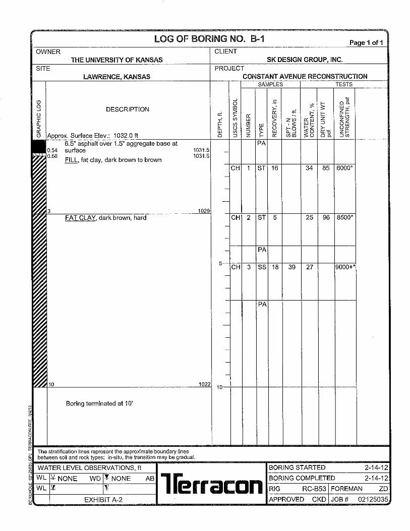
3.0 SUBSURFACE CONDITIONS 3.1 Soil and Bedrock Conditions The ground surface elevations at the boring locations range from about 1032 feet at Boring B-1 (just west of the Irving Hill Road bridge over Iowa Street) to about 964 feet at Boring B-11 (on Constant Avenue just south of 19th Street) and 965 feet at B-13 (on 19th Street just west of Iowa Street). Conditions encountered at each boring location are presented on the boring logs. Stratification boundaries on the boring logs represent the approximate location of changes in soil and rock types; in-situ, the transition between materials usually occurs gradually. The asphalt pavement thickness at the boring locations ranged from 5 to 8.5 inches. The asphalt pavement is supported on a crushed aggregate base course. At the boring locations, the apparent aggregate base thickness ranged from 1.5 to 3 inches. It is possible that a slightly thicker aggregate base could have been initially placed; a thin layer of clayey aggregate was noted below the aggregate layer, which suggests clay soil intrusion. The subgrades immediately below the existing pavement at the boring locations are comprised predominately of fat clay soils (native soils and fills) or severely weathered shale that exhibits consistency similar to very stiff to hard clay. At Borings B-7 and B-13, the strata immediately below the pavement are harder. Apparent thin limestone strings were encountered at some borings and auger refusal in limestone strata occurred at Borings B-4 (8.4 feet), B-6 (9.3 feet), B-7 (2.5 feet) and B-8 (6.4 feet). The other borings were terminated as planned at a depth of 10 feet. Although apparent limestone strata were not encountered at depths shallower than 2.5 feet at the boring locations, the borings were widely spaced. It is possible that limestone strata could be present at shallower depths along unexplored sections of the alignments. Limestone can be somewhat more porous than shale and clay soil. Groundwater can migrate downward along vertical joints and laterally along seams and bedding planes in limestone.
Preliminary Geotechnical Engineering Report Constant Avenue Reconstruction ■ Lawrence, KS March 5, 2012 ■ Project No. 020125035
Responsive ■ Resourceful ■ Reliable 3
3.2 Groundwater Observations The boreholes were observed while drilling and after completion for the presence and level of water. Groundwater was not observed at either of these times at any of the borings. Due to relatively low permeability of the clay soils and shale encountered in the borings, a long period of time may be necessary for a groundwater level to develop and stabilize in a borehole in these materials. The borings were widely spaced so groundwater conditions could be different in unexplored areas. Long term observations in piezometers or observation wells sealed from the influence of surface water would be required to develop further opinions concerning groundwater conditions. Groundwater levels fluctuate due to seasonal variations in the amount of rainfall, runoff and other factors not evident at the time the borings were performed so groundwater conditions at other times may differ from those indicated on the boring logs. The possibility of groundwater level fluctuations should be considered when developing the design and construction plans for the project.
4.0 PRELIMINARY ENGINEERING RECOMMENDAITONS
4.1 Geotechnical Considerations Fat clay soils (native and fill materials) and severely weathered shales that exhibit soil-like consistency are not an ideal pavement subgrade material. Clay soil/severely weathered shale is a poorly drained material, subject to volume change with moisture variation and susceptible to strength loss when wetted. Although stability of subgrades comprised of fat clay soils/severely weathered shale can be improved by chemical stabilization, such as incorporation of lime or Class C fly ash, in our opinion, based on the necessity of project completion by August 7, 2012, an aggregate base course should be used below new pavements in lieu of chemical stabilization. Surface and subsurface water should be intercepted and/or redirected to reduce the potential for subgrade saturation, which can result in loss of subgrade support and premature pavement distress and deterioration. In our opinion, edge drains should be provided along each side of the reconstructed Constant Avenue and 19th Street alignments. Edge drains should be considered along at least the western part of the Irving Hill alignment where water does not drain rapidly away to the north and south from the pavement. Although apparent limestone strata were not encountered at depths shallower than 2.5 feet at the boring locations, the borings were widely spaced. To account for the possibility that water bearing limestone strata could be present at shallower depths along unexplored sections of the alignments, the plans should include a subsurface blanket drain detail. The blanket drain should be installed wherever limestone strata are encountered at subgrade level. Undergrading

Preliminary Geotechnical Engineering Report Constant Avenue Reconstruction ■ Lawrence, KS March 5, 2012 ■ Project No. 020125035
Responsive ■ Resourceful ■ Reliable 4
of the limestone will be required to accommodate placement of the blanket drainage material below the crushed aggregate base course. The blanket drain should be hydraulically connected to the edge drain system.
4.2 Subgrade Preparation At the on-set of construction, the existing pavement surface should be removed. If the asphalt can be recycled, the material could be delivered to a local asphalt plant. The new street construction will follow the existing alignment. Nevertheless, any vegetation or topsoil noted along the new alignment should also be stripped. After the existing pavement section has been removed and the subgrade has been undercut where necessary to accommodate the new pavement section, but before any fill or aggregate base is placed, we recommend the exposed subgrade be proof-rolled to help delineate soft or unstable areas that may exist within the upper zone of the subgrade. Soils that rut, pump or deflect excessively when wheel rolled should be undercut and replaced with additional compacted aggregate base material. Proof-rolling should be accomplished with a loaded tandem axle dump truck, or other rubber tired construction equipment having a minimum gross weight of 25 tons. After this initial proof-rolling is complete, the subgrade surface should be scarified to a depth of 6 inches, moisture conditioned and compacted as recommended for fill. If limestone bedrock strata are encountered at subgrade level, it should be undercut as required to accommodate placement of a blanket drain. Recommendations for surface and subsurface drainage are provided later in this report.
4.3 Engineered Fill
Engineered fill, including any soil fill needed to raise profile grades as well as crushed aggregate base course material and drainage material should be free of organic matter and debris. Fill should not be frozen and should not be placed on frozen surfaces (not expected to be an issue during the expected Spring/Summer construction period). Fill should be placed in 9-inch thick (maximum) loose lifts. Each lift should be uniformly compacted to at least 95 percent of the material’s maximum density determined under standard effort (ASTM D 698). Moisture content of clay soils (scarified subgrade and fill materials) should be in the range of minus 2 to plus 2 percent of the optimum moisture content determined by ASTM D 698 at the time of compaction. Crushed aggregate base course material should have sufficient moisture to achieve compaction without rutting or pumping. Clean granular drainage material should be compacted to a dense, stable condition.

Preliminary Geotechnical Engineering Report Constant Avenue Reconstruction ■ Lawrence, KS March 5, 2012 ■ Project No. 020125035
Responsive ■ Resourceful ■ Reliable 5
4.4 Preliminary Opinions of Pavement Thickness Terracon considered transit busses traversing the reconstructed alignments would have one front axle carrying 6.000 pounds and one rear axle carrying 18,000 pounds. 2,070,000 equivalent single axle load (ESAL) repetitions are estimated over the design period for both PCC and HMA pavements. Actual axle load data should be obtained from the bus manufacturer, Terracon offers the following preliminary opinions concerning pavement sections and their thickness:
In our opinion, a 6-inch thick (minimum) layer of compacted crushed aggregate base material, such as KDOT Type AB-3, should be used below HMA and PCC pavements.
No groundwater was encountered at the borings. The clay soil/severely weathered
shale subgrade materials are relatively poorly drained. Provided the areas alongside the alignments are sloped so water drains away from pavements, free-draining drainage layers below PCC or HMA pavements that are connected to properly designed edge drains are not mandatory.
In our opinion, subject to verification of the projected ESAL values, a PCC pavement
having a total thickness of 9 inches supported on 6-inch thick compacted crushed aggregate base course should provide adequate support for the described traffic.
In our opinion, subject to verification of the projected ESAL values, an HMA Superpave
pavement having a total thickness of 12 inches supported on 6-inch thick compacted crushed aggregate base course should provide adequate support for the described traffic.
4.4.1 Choice of Pavement Material The choice between PCC and HMA pavement will depend on a number of factors. Terracon understands KU will decide. We offer the following opinions, based on our observations and experience:
Loaded busses impart high stresses to pavements when stopping and turning, which can cause HMA pavements to rut, shove and distort. PCC pavements are less susceptive to these stresses.
HMA Pavements develop distress due to thermal stresses over time. PCC pavements with dowelled joints are less susceptible.
Construction and repair of subsurface utility lines below PCC pavements, which
require removal and replacement of PCC pavement sections, can be more

Preliminary Geotechnical Engineering Report Constant Avenue Reconstruction ■ Lawrence, KS March 5, 2012 ■ Project No. 020125035
Responsive ■ Resourceful ■ Reliable 6
expensive than repair of HMA pavement. However, once HMA pavements have been cut, it is difficult to reconstruct a pavement having the same uniformity. In our opinion, to avoid subsequent pavement cuts for future utility installation, an appropriate number and size of conduits should be installed before pavements are constructed.
PCC pavements are susceptible to deterioration due to chloride ion attack, D-
cracking and alkali-silica reaction. Selection of an appropriate concrete mix is important. We recommend a KCMMB (Kansas City Metro Materials Board) approved concrete mix be specified for this project.
4.4.2 Pavement Surface Drainage Wherever possible, the pavement surface should be sloped to provide rapid drainage of surface water to storm sewer inlets. Wherever possible, the grades along each side of the alignments should be sloped so surface water will drain away from the pavement. Water that ponds on or adjacent to pavement surfaces could penetrate or seep under the pavement, saturate the subgrade and contribute to premature pavement deterioration.
4.4.3 Pavement Subsurface Drainage Much of the area to the northeast of the Constant Avenue alignment will drain west and southwest toward the new street. Surface water will drain over the curb and then drain to inlets. It is likely that subsurface groundwater will drain toward the street in a similar manner. We recommend edge drains be installed along each side of Constant Avenue, 19th Street and at least the western portion of Irving Hill Road where the ground surface will not slope down to the north and south from the pavement curbs. Edge drain details extracted from the detail sheet produced by the Kansas City Metropolitan Chapter APWA are shown below for ease of reference.
Although apparent limestone strata were not encountered at depths shallower than 2.5 feet at the boring locations, the borings were widely spaced. To account for the possibility that water bearing limestone strata could be present at shallower depths along unexplored sections of the alignments, we recommend the plans include a subsurface blanket drain detail. The detail

Preliminary Geotechnical Engineering Report Constant Avenue Reconstruction ■ Lawrence, KS March 5, 2012 ■ Project No. 020125035
Responsive ■ Resourceful ■ Reliable 7
shown in the figure below was extracted from the detail sheet produced by the Kansas City Metropolitan Chapter APWA.
The blanket drain should be installed wherever limestone strata are encountered at subgrade level. Undergrading of the limestone will be required to accommodate placement of the blanket drainage material below the crushed aggregate base course. The limestone should be undercut at least 8 inches below the base of the crushed aggregate base course layer. Greater undergrading will be required at the pipe location. The blanket drain should not extend deeper than the adjacent edge drain to prevent backflow of water from the edge drain into the blanket drain. The pipe at the base of the blanket drain should be connected to the edge drain system so water will flow to a suitable down-gradient outlet. Drainage aggregate used in edge and blanket drainage systems should be as specified on the detail sheet produced by the Kansas City Metropolitan Chapter APWA.
4.4.4 Pavement Maintenance Pavement thickness determination methods are intended to provide adequate thickness of structural materials over a particular subgrade such that wheel loads are reduced to a level that the subgrade can support. The subgrade support parameters for pavement thickness design do not account for shrink/swell movements of a subgrade constructed of expansive clay soils like those encountered at the borings or softening of the clay subgrade soils caused by surface water infiltration. Therefore, the pavement may be adequate from a structural standpoint, yet still experience cracking and deformation due to shrink/swell related movement of the subgrade or moisture changes in the subgrade. The pavement sections provided in this report represent minimum recommended thicknesses. Consequently, pavements must be properly maintained or they will deteriorate prematurely.
Preliminary Geotechnical Engineering Report Constant Avenue Reconstruction ■ Lawrence, KS March 5, 2012 ■ Project No. 020125035
Responsive ■ Resourceful ■ Reliable 8
Pavement maintenance should include regular sealing of joints. Cracks should be sealed and distressed areas should be repaired as they develop. Even with a regular maintenance program, some movements and related cracking may still occur and repairs may be required.
4.5 Construction Considerations Pavement subgrades are susceptible to disturbance by repetitive heavy wheel loads that most often occur during the pavement laydown operations. Loaded trucks back continuously over the same route to an asphalt spreader. Repetitive traffic can result in deformation, pumping, and rutting. Removal of the rutted, disturbed subgrade during paving operations and replacement with thicker asphalt results in a thicker section in some areas. While this remedial treatment is beneficial, it results in non-uniform thickness. Even with a thicker asphalt section, the lift is often too thick to be well compacted at the bottom. For these reasons, where HMA pavements are to be constructed, we recommend subgrades be repetitively proofrolled with loaded trucks several days in advance of paving so that low density or otherwise unsuitable areas can be corrected before paving begins. Particular attention should be paid to high traffic areas that were rutted and disturbed earlier and to backfilled trenches. Areas that pump or rut should be undercut and replaced with properly placed and compacted fill and then proofrolled again. We recommend that Terracon be retained to provide construction observation and testing services in conjunction with subgrade preparation, lime or fly ash stabilization, fill placement and compaction. We can also provide any required observations and tests of the asphaltic concrete pavements.
5.0 GENERAL COMMENTS Terracon should be retained to review the final design plans and specifications so comments can be made regarding interpretation and implementation of our geotechnical recommendations in the design and specifications. Terracon also should be retained to provide observation and testing services during grading, excavation, foundation construction and other earth-related construction phases of the project. The analysis and preliminary recommendations presented in this report are based upon the data obtained from the borings performed at the indicated locations and from other information discussed in this report. This report does not reflect variations that may occur between borings, across the site, or due to the modifying effects of construction or weather. The nature and extent of such variations may not become evident until during or after construction. If variations appear, we should be immediately notified so that further evaluation and supplemental recommendations can be provided.

Preliminary Geotechnical Engineering Report Constant Avenue Reconstruction ■ Lawrence, KS March 5, 2012 ■ Project No. 020125035
Responsive ■ Resourceful ■ Reliable 9
The scope of services for this project does not include either specifically or by implication any environmental or biological (e.g., mold, fungi, bacteria) assessment of the site or identification or prevention of pollutants, hazardous materials or conditions. If the owner is concerned about the potential for such contamination or pollution, other studies should be undertaken. This preliminary report has been prepared for the exclusive use of our client for specific application to the project discussed and has been prepared in accordance with generally accepted geotechnical engineering practices. No warranties, express or implied, are intended or made. Site safety, excavation support, and dewatering requirements are the responsibility of others. In the event that changes in the nature, design, or location of the project as outlined in this report are planned, the conclusions and recommendations contained in this report shall not be considered valid unless Terracon reviews the changes and either verifies or modifies the conclusions of this report in writing.

APPENDIX A
FIELD EXPLORATION

A-1
Exhibit BORING LOCATION DIAGRAM
CONSTANT AVENUE
RECONSTRUCTION
LAWRENCE, KANSAS
Project Manager:
Drawn By:
Checked By:
Approved By:
CKD
3/4/12
Project No.
Scale:
File Name:
Date: 13910 West 96th Terrace Lenexa, KS 66215
PH. (913) 492-7777 FAX. (913) 492-7443
CKD
CKD
CKD
Boring Location (8.5x11).ppt
02125035
N.T.S.
DIAGRAM IS FOR GENERAL LOCATION ONLY, AND IS NOT
INTENDED FOR CONSTRUCTION PURPOSES
B-1
B-2
B-3
B-4
B-5
B-6
B-7
B-8
B-9
B-11 B-13
B-10
B-12


Preliminary Geotechnical Engineering Report Constant Avenue Reconstruction ■ Lawrence, KS March 5, 2012 ■ Project No. 020125035
Exhibit A-15
Field Exploration Description Boring locations were selected by Terracon. Boring locations were plotted on a topographic plan of the alignment furnished by SK Design. The drill crew located borings in the field using terrain association techniques. Approximate boring locations are shown on Exhibit A-1. Ground surface elevations at the boring locations were interpolated by Terracon to the nearest ½ foot using the contours shown on the topographic plan of the alignment. Locations and elevations of the borings should be considered accurate only to the degree implied by the measurement methods. The borings were drilled with a rotary drill rig using continuous flight augers to advance the boreholes. Representative samples were obtained using thin-walled tube and split-barrel sampling procedures. In the thin-walled tube sampling procedure, a 2-inch diameter, thin-walled, seamless steel tube with a sharp cutting edge is pushed hydraulically into the soil to obtain a relatively undisturbed sample. In the split-barrel sampling procedure, a standard 2-inch O.D. split-barrel sampling spoon is driven into the ground by a 140-pound hammer falling a distance of 30 inches. The number of blows required to advance the sampling spoon the last 12 inches of a normal 18-inch penetration is recorded as the Standard Penetration Test (SPT) resistance value. The SPT resistance values, also referred to as N-values, are indicated on the boring logs at the test depths. The samples were tagged for identification, sealed to reduce moisture loss and returned to the laboratory for testing and classification. The samples were tagged for identification, sealed in their tubes or placed in plastic containers to reduce moisture loss and returned to our laboratory. Boreholes were backfilled upon completion. A field log of each boring was prepared by the drill crew to record data including visual classifications of the materials encountered during drilling and the driller’s interpretation of the subsurface conditions between samples. The boring logs in this appendix represent Terracon’s opinion of the subsurface conditions at each boring based on the field and laboratory data and observation of the samples.

APPENDIX B
LABORATORY TESTS

Preliminary Geotechnical Engineering Report Constant Avenue Reconstruction ■ Lawrence, KS March 5, 2012 ■ Project No. 020125035
Exhibit B-1
Laboratory Tests Samples were tested in the laboratory to measure their natural water content and dry unit weight. A calibrated hand penetrometer was used to estimate the approximate unconfined compressive strength of some samples. The calibrated hand penetrometer has been correlated with unconfined compression tests and provides a better estimate of soil consistency than visual examination alone. The test results are provided on the boring logs included in Appendix A. Descriptive classifications of the soils indicated on the boring logs are in accordance with the enclosed General Notes and the Unified Soil Classification System. Also shown are estimated Unified Soil Classification Symbols. A brief description of this classification system is attached to this report.

APPENDIX C
SUPPORTING DOCUMENTS

Exhibit C-1
GENERAL NOTES
DRILLING & SAMPLING SYMBOLS: SS: Split Spoon – 1-3/8" I.D., 2" O.D., unless otherwise noted HS: Hollow Stem Auger ST: Thin-Walled Tube - 2" O.D., unless otherwise noted PA: Power Auger RS: Ring Sampler - 2.42" I.D., 3" O.D., unless otherwise noted HA: Hand Auger DB: Diamond Bit Coring - 4", N, B RB: Rock Bit BS: Bulk Sample or Auger Sample WB: Wash Boring or Mud Rotary
The number of blows required to advance a standard 2-inch O.D. split-spoon sampler (SS) the last 12 inches of the total 18-inch penetration with a 140-pound hammer falling 30 inches is considered the “Standard Penetration” or “N-value”.
WATER LEVEL MEASUREMENT SYMBOLS:
WL: Water Level WS: While Sampling N/E: Not Encountered WCI: Wet Cave in WD: While Drilling DCI: Dry Cave in BCR: Before Casing Removal AB: After Boring ACR: After Casing Removal Water levels indicated on the boring logs are the levels measured in the borings at the times indicated. Groundwater levels at other times and other locations across the site could vary. In pervious soils, the indicated levels may reflect the location of groundwater. In low permeability soils, the accurate determination of groundwater levels may not be possible with only short-term observations. DESCRIPTIVE SOIL CLASSIFICATION: Soil classification is based on the Unified Classification System. Coarse Grained Soils have more than 50% of their dry weight retained on a #200 sieve; their principal descriptors are: boulders, cobbles, gravel or sand. Fine Grained Soils have less than 50% of their dry weight retained on a #200 sieve; they are principally described as clays if they are plastic, and silts if they are slightly plastic or non-plastic. Major constituents may be added as modifiers and minor constituents may be added according to the relative proportions based on grain size. In addition to gradation, coarse-grained soils are defined on the basis of their in-place relative density and fine-grained soils on the basis of their consistency.
CONSISTENCY OF FINE-GRAINED SOILS RELATIVE DENSITY OF COARSE-GRAINED SOILS
Unconfined Compressive
Strength, Qu, psf
Standard Penetration or N-value (SS)
Blows/Ft. Consistency
Standard Penetration or N-value (SS)
Blows/Ft.
Ring Sampler (RS) Blows/Ft.
Relative Density
< 500 <2 Very Soft 0 – 3 0-6 Very Loose 500 – 1,000 2-3 Soft 4 – 9 7-18 Loose
1,001 – 2,000 4-6 Medium Stiff 10 – 29 19-58 Medium Dense 2,001 – 4,000 7-12 Stiff 30 – 49 59-98 Dense 4,001 – 8,000 13-26 Very Stiff 50+ 99+ Very Dense
8,000+ 26+ Hard
RELATIVE PROPORTIONS OF SAND AND GRAVEL GRAIN SIZE TERMINOLOGY Descriptive Term(s) of other
Constituents Percent ofDry Weight
Major Componentof Sample
Particle Size
Trace < 15 Boulders Over 12 in. (300mm) With 15 – 29 Cobbles 12 in. to 3 in. (300mm to 75 mm)
Modifier > 30 Gravel 3 in. to #4 sieve (75mm to 4.75 mm)
Sand
Silt or Clay #4 to #200 sieve (4.75mm to 0.075mm)
Passing #200 Sieve (0.075mm)
RELATIVE PROPORTIONS OF FINES PLASTICITY DESCRIPTION
Descriptive Term(s) of other Constituents
Percent ofDry Weight
Term Plasticity
Index
Trace < 5 Non-plastic 0 With 5 – 12 Low 1-10
Modifiers > 12 Medium 11-30 High 30+

Exhibit C-2
UNIFIED SOIL CLASSIFICATION SYSTEM
Criteria for Assigning Group Symbols and Group Names Using Laboratory Tests A Soil Classification
Group Symbol
Group Name B
Coarse Grained Soils: More than 50% retained on No. 200 sieve
Gravels: More than 50% of coarse fraction retained on No 4 sieve
Clean Gravels: Less than 5% fines C
Cu 4 and 1 Cc 3 E GW Well-graded gravel F
Cu 4 and/or 1 Cc 3 E GP Poorly graded gravel F
Gravels with Fines: More than 12% fines C
Fines classify as ML or MH GM Silty gravel F,G, H
Fines classify as CL or CH GC Clayey gravel F,G,H
Sands: 50% or more of coarse fraction passes No. 4 sieve
Clean Sands: Less than 5% fines D
Cu 6 and 1 Cc 3 E SW Well-graded sand I
Cu 6 and/or 1 Cc 3 E SP Poorly graded sand I
Sands with Fines: More than 12% fines D
Fines classify as ML or MH SM Silty sand G,H,I
Fines Classify as CL or CH SC Clayey sand G,H,I
Fine-Grained Soils: 50% or more passes the No. 200 sieve
Silts and Clays: Liquid limit less than 50
Inorganic: PI 7 and plots on or above “A” line J CL Lean clay K,L,M
PI 4 or plots below “A” line J ML Silt K,L,M
Organic: Liquid limit - oven dried
0.75 OL Organic clay K,L,M,N
Liquid limit - not dried Organic silt K,L,M,O
Silts and Clays: Liquid limit 50 or more
Inorganic: PI plots on or above “A” line CH Fat clay K,L,M
PI plots below “A” line MH Elastic Silt K,L,M
Organic: Liquid limit - oven dried
0.75 OH Organic clay K,L,M,P
Liquid limit - not dried Organic silt K,L,M,Q
Highly organic soils: Primarily organic matter, dark in color, and organic odor PT Peat
A Based on the material passing the 3-in. (75-mm) sieve B If field sample contained cobbles or boulders, or both, add “with cobbles
or boulders, or both” to group name. C Gravels with 5 to 12% fines require dual symbols: GW-GM well-graded
gravel with silt, GW-GC well-graded gravel with clay, GP-GM poorly graded gravel with silt, GP-GC poorly graded gravel with clay.
D Sands with 5 to 12% fines require dual symbols: SW-SM well-graded sand with silt, SW-SC well-graded sand with clay, SP-SM poorly graded sand with silt, SP-SC poorly graded sand with clay
E Cu = D60/D10 Cc =
6010
2
30
DxD
)(D
F If soil contains 15% sand, add “with sand” to group name. G If fines classify as CL-ML, use dual symbol GC-GM, or SC-SM.
H If fines are organic, add “with organic fines” to group name. I If soil contains 15% gravel, add “with gravel” to group name. J If Atterberg limits plot in shaded area, soil is a CL-ML, silty clay. K If soil contains 15 to 29% plus No. 200, add “with sand” or “with
gravel,” whichever is predominant. L If soil contains 30% plus No. 200 predominantly sand, add “sandy”
to group name. M If soil contains 30% plus No. 200, predominantly gravel, add
“gravelly” to group name. N PI 4 and plots on or above “A” line. O PI 4 or plots below “A” line. P PI plots on or above “A” line. Q PI plots below “A” line.

Exhibit C-3
GENERAL NOTES Description of Rock Properties
WEATHERING
Fresh Rock fresh, crystals bright, few joints may show slight staining. Rock rings under hammer if crystalline.
Very slight Rock generally fresh, joints stained, some joints may show thin clay coatings, crystals in broken face show bright. Rock rings under hammer if crystalline.
Slight Rock generally fresh, joints stained, and discoloration extends into rock up to 1 in. Joints may contain clay. In granitoid rocks some occasional feldspar crystals are dull and discolored. Crystalline rocks ring under hammer.
Moderate Significant portions of rock show discoloration and weathering effects. In granitoid rocks, most feldspars are dull and discolored; some show clayey. Rock has dull sound under hammer and shows significant loss of strength as compared with fresh rock.
Moderately severe All rock except quartz discolored or stained. In granitoid rocks, all feldspars dull and discolored and majority show kaolinization. Rock shows severe loss of strength and can be excavated with geologist’s pick.
Severe All rock except quartz discolored or stained. Rock “fabric” clear and evident, but reduced in strength to strong soil. In granitoid rocks, all feldspars kaolinized to some extent. Some fragments of strong rock usually left.
Very severe All rock except quartz discolored or stained. Rock “fabric” discernible, but mass effectively reduced to “soil” with only fragments of strong rock remaining.
Complete Rock reduced to”soil”. Rock “fabric” not discernible or discernible only in small, scattered locations. Quartz may be present as dikes or stringers.
HARDNESS (for engineering description of rock – not to be confused with Moh’s scale for minerals)
Very hard Cannot be scratched with knife or sharp pick. Breaking of hand specimens requires several hard blows of geologist’s pick.
Hard Can be scratched with knife or pick only with difficulty. Hard blow of hammer required to detach hand specimen.
Moderately hard Can be scratched with knife or pick. Gouges or grooves to ¼ in. deep can be excavated by hard blow of point of a geologist’s pick. Hand specimens can be detached by moderate blow.
Medium Can be grooved or gouged 1/16 in. deep by firm pressure on knife or pick point. Can be excavated in small chips to pieces about 1-in. maximum size by hard blows of the point of a geologist’s pick.
Soft Can be gouged or grooved readily with knife or pick point. Can be excavated in chips to pieces several inches in size by moderate blows of a pick point. Small thin pieces can be broken by finger pressure.
Very soft Can be carved with knife. Can be excavated readily with point of pick. Pieces 1-in. or more in thickness can be broken with finger pressure. Can be scratched readily by fingernail.
Joint, Bedding, and Foliation Spacing in Rock a
Spacing Joints Bedding/Foliation
Less than 2 in. Very close Very thin 2 in. – 1 ft. Close Thin 1 ft. – 3 ft. Moderately close Medium
3 ft. – 10 ft. Wide Thick More than 10 ft. Very wide Very thick
a. Spacing refers to the distance normal to the planes, of the described feature, which are parallel to each other or nearly so.
Rock Quality Designator (RQD) a Joint Openness Descriptors
RQD, as a percentage Diagnostic description Openness Descriptor
Exceeding 90 Excellent No Visible Separation Tight 90 – 75 Good Less than 1/32 in. Slightly Open 75 – 50 Fair 1/32 to 1/8 in. Moderately Open 50 – 25 Poor 1/8 to 3/8 in. Open
Less than 25 Very poor 3/8 in. to 0.1 ft. Moderately Wide Greater than 0.1 ft. Wide
a. RQD (given as a percentage) = length of core in pieces 4 in. and longer/length of run. References: American Society of Civil Engineers. Manuals and Reports on Engineering Practice - No. 56. Subsurface Investigation for Design
and Construction of Foundations of Buildings. New York: American Society of Civil Engineers, 1976. U.S. Department of the Interior, Bureau of Reclamation, Engineering Geology Field Manual.