preliminary geotechnical engineering report state highway ... · appendix a5 preliminary...
TRANSCRIPT

APPENDIX A5
PRELIMINARY GEOTECHNICAL ENGINEERING REPORT
FOR THE
State Highway 9 Iron Springs Alignment
Environmental Assessment
Prepared for
COLORADO DEPARTMENT OF TRANSPORTATION
FEDERAL HIGHWAY ADMINISTRATION
Report Prepared by
YEH AND ASSOCIATES, INC.
December 2010

Preliminary Geotechnical Engineering Report for the State Highway 9 Iron Springs Alignment EA
APRIL 2014
ADDENDUM/CLARIFICATION TO THE PRELIMINARY GEOTECHNICAL ENGINEERING REPORT STATE HIGHWAY 9 DILLON RESERVOIR ALIGNMENT EVALUATION
The Preliminary Geotechnical Engineering Report was prepared in 2010 before the refinement of the
conceptual design for the Proposed Action. As a result, some of the terminology used to describe the
project alternative has changed since the preparation of the Preliminary Geotechnical Engineering
Report. In addition some details of the conceptual design have changed since the Preliminary
Geotechnical Engineering Report was prepared.
The Preliminary Geotechnical Engineering Report provides appropriate background information for this
Environmental Assessment (EA) analysis, and thus is included as a supporting technical appendix to the
EA. The following changes in terminology and detail since preparation of the report should be noted:
Names of Alternatives: The Preliminary Geotechnical Engineering Report provides information
on two alignment alternatives. The alternative referred to as the “Lake Dillon Alternative” in
Table 1 (page 24) is equivalent to the No Action Alternative (widening on existing alignment) as
identified the EA and other supporting technical appendices. The alternative referred to as the
“Iron Springs Alignment” in Table 1 is the Proposed Action as identified in the EA and other
supporting technical appendices.
Alternative Details: Section 10.0 Bridge Foundation Recommendations (page 18) is no longer
applicable as the conceptual designs for the Proposed Action and the No Action Alternative (see
Appendix A1) do not include any bridges. Table 1 (page 24) indicates “Retaining walls not
required” for the Iron Springs Alignment (Proposed Action). This is no longer accurate, as the
Proposed Action includes some retaining walls as shown in Appendix A1 and described in the EA
and other supporting technical appendices. The retaining walls required in the Proposed Action
would be less extensive than those required in the No Action Alternative.

Yeh and Associates, Inc. Consulting Engineers & Scientists
Preliminary Geotechnical Engineering Report
SH 9 Dillon Reservoir Alignment Evaluation
Summit County, Colorado
December 10, 2010
Project No. 210-147
Prepared for:
PBS&J 4601 DTC Boulevard, Suite 700
Denver, Colorado 80237 Attn: Mr. Wes Goff, P.E.
Colorado Department of Transportation Region 1, Mountain Residency
PO Box 399 Dumont, Colorado 80436
Attn: Mr. Tyler Weldon, P.E.
Prepared by:
Yeh and Associates, Inc. 5700 E. Evans Ave.
Denver, Colorado 80222 Phone 303-781-9590 Fax: 303-781-9583

SH 9 SH 9 Dillon Reservoir Alignment Evaluation YA Project No. 210-147 Preliminary Geotechnical Investigation Report Summit County, Colorado
i
Table of Contents
Page
1.0 Purpose and Scope of Study ............................................................................. 1
2.0 Proposed Construction ...................................................................................... 2
3.0 Site Conditions ................................................................................................... 2
4.0 Regional Geology ............................................................................................... 3
4.1 Surficial Deposits .................................................................................. 4
Artificial fill .................................................................................................... 5
Bouldery gravel of the Gold Run (middle - lower Pleistocene to Pliocene) .. 5
Till of Bull Lake glaciation (middle Pleistocene) ........................................... 6
4.2 Bedrock ................................................................................................. 6
Dakota Sandstone (Lower Cretaceous) ....................................................... 6
Quartz Monzonite Porphyry (Eocene) .......................................................... 7
5.0 Seismicity ............................................................................................................ 7
5.1 Seismic Concern ................................................................................... 7
5.2 Seismic Design Parameters .................................................................. 7
6.0 Bedrock Outcrop Mapping ................................................................................ 7
6.1 Cut Slope Bedrock Mapping and Kinematic Analysis ........................... 7
Proposed Rock Cut Section 1 – Approximately Sta. 1+00 to 10+00 ............ 9
Proposed Rock Cut Section 2 – Approximately Sta. 13+50 to 16+00 ........ 10
Proposed Rock Cut Section 3 – Approximately Sta. 17+00 to 25+00 ........ 11
7.0 Subsurface Investigation ................................................................................. 13
7.1 Geotechnical Borings .......................................................................... 13
7.2 Geophysical Survey ............................................................................ 15

SH 9 SH 9 Dillon Reservoir Alignment Evaluation YA Project No. 210-147 Preliminary Geotechnical Investigation Report Summit County, Colorado
ii
8.0 Laboratory Testing ........................................................................................... 16
9.0 Geologic Hazards and Engineering Constraints ........................................... 16
9.1 Loose Subsurface Materials ............................................................... 17
9.2 Landslides ........................................................................................... 17
9.3 Soil Corrosivity .................................................................................... 18
10.0 Bridge Foundation Recommendations ........................................................... 18
11.0 Wall Recommendations ................................................................................... 19
12.0 Cut Walls ........................................................................................................... 19
12.1 Ground Nail Walls ............................................................................... 19
12.2 Ground Anchor Walls .......................................................................... 19
13.0 Fill Walls ............................................................................................................ 20
13.1 Mechanically Stabilized Earth (MSE) Walls ........................................ 20
13.2 Cantilever Walls .................................................................................. 20
14.0 Site Grading ...................................................................................................... 20
14.1 Cut Slopes .......................................................................................... 21
14.2 Fill Slopes ........................................................................................... 21
15.0 Surface Drainage .............................................................................................. 22
16.0 Comparison of Alignment Alternatives .......................................................... 22
17.0 Limitations ........................................................................................................ 25
18.0 References ........................................................................................................ 26

SH 9 SH 9 Dillon Reservoir Alignment Evaluation YA Project No. 210-147 Preliminary Geotechnical Investigation Report Summit County, Colorado
iii
Appendices
APPENDIX A- Project Location Map ................................................................. 27
APPENDIX B- Site Investigation Map ............................................................... 28
APPENDIX C- Geology Map and Legend ......................................................... 29
APPENDIX D- Seismic Design Spectra ............................................................ 30
APPENDIX E- Existing Rockcut Evaluation ...................................................... 31
APPENDIX F- Engineering Geology Sheets and Boring Logs .......................... 32
APPENDIX G- Photographs of Rock Core ........................................................ 33
APPENDIX H- Tomographs .............................................................................. 34
APPENDIX I- Laboratory Test Results .............................................................. 35

SH 9 SH 9 Dillon Reservoir Alignment Evaluation YA Project No. 210-147 Preliminary Geotechnical Investigation Report Summit County, Colorado
1
1.0 Purpose and Scope of Study
This report presents the results of our preliminary geotechnical study for the
evaluation of two alignment alternatives associated with the roadway widening of State
Highway 9, west of the Blue River drainage of Dillon Reservoir in Summit County,
Colorado with specific emphasis on the eastern side of the alignments that look
westward over the Blue River arm of Lake Dillon (Sta. 0+00 through approximately Sta.
35+00 of the first alternative alignment that follows existing State Highway 9) and the
fen crossing (natural resources). The study area is located between Swan Mountain
Road and Frisco, which corresponds approximately to Mile Markers 93 through 97 (see
Appendix A. Project Location Map).
The purpose of our study was to identify and evaluate general geotechnical
characteristics of the subsurface soils and bedrock along the highway, to conduct
preliminary geotechnical analyses, to provide preliminary geotechnical
recommendations and parameters for the proposed cut and fill slopes and structures
and provide a general constructability assessment of the two proposed alignment
alternatives. The study was conducted in general accordance with our scope of work
dated March 17, 2010
A field exploration program consisting of geologic reconnaissance, bedrock
structure mapping, geophysical survey and exploratory drilling was conducted to obtain
information on subsurface conditions. Between September 28, 2010 and October 6,
2010, 6 geotechnical borings were observed and logged by CDOT representatives and
3 biological borings were observed and logged by a representative with PKM Design
Group, Inc. Of these 9 borings, 5 were drilled along SH 9 and 4 were drilled west of
SH 9 on the slopes for the alternative new alignment (see Appendix B. Site
Investigation Map). Subsurface material samples were obtained during the field
exploration and examined by the project personnel. Representative samples were
tested in our laboratory to determine the classification and engineering characteristics
of the on-site material.
Based on the information obtained, Yeh and Associates has completed an
evaluation of subsurface conditions. This report summarizes the data gathered, the
SH 9 SH 9 Dillon Reservoir Alignment Evaluation YA Project No. 210-147 Preliminary Geotechnical Investigation Report Summit County, Colorado
2
results of our analysis and our recommendations based on the proposed construction,
site reconnaissance, geotechnical subsurface investigation, and results of laboratory
testing. General cut and fill slopes and structures recommendations and a discussion
of the geotechnical engineering considerations are included in this report.
2.0 Proposed Construction
Two alternatives are proposed for the SH 9 alignment through this area. The first
alignment will generally follow the existing SH 9 route associated with proposed
widening by expanding the current two-lane configuration into a four-lane roadway.
The second alignment would follow a more direct route from Farmers corner to Frisco
with a four -lane configuration. Both alternatives will require both cut and fill sections
on either the existing SH 9 alignment or the open space on the west slope. The
construction of a bridge is also proposed over the fen area approximately between Sta.
8+00 and Sta. 9+00.
3.0 Site Conditions
The existing highway slopes from south to north through the study area with an
approximate elevation gain of approximately 10 feet between Sta. 0+00 and Sta.
40+00. The existing SH 9 on the northeast side of the project area generally follows
the rim of Dillon Reservoir and turns southwest at the north end of the project area.
Most of the existing SH 9 in the east side of the project area is cut with cut slopes
ranging from 1.3H:1V to 0.4H:1V. The southern section of the existing highway (Sta.
0+00 to 40+00) consists of cut slopes in quartzite of the order of 20 to 30 feet high and
as steep as 1.3H:1V in areas. These cuts are generally stable, with some surficial
erosion (raveling), except where the middle shale member of the formation is exposed
in the slope face (for example approximately Sta. 5+00, first alignment alternative). A
slope failure in the cut slope of 1.3H:1V occurs approximately this point. The failed
slope comprises sandstone, carbonaceous shale with a little clay. Several minor to
severe cracks were observed on the pavement.
The project area consists of undeveloped, public land under the jurisdiction of
the National Forest System and Summit County.

SH 9 SH 9 Dillon Reservoir Alignment Evaluation YA Project No. 210-147 Preliminary Geotechnical Investigation Report Summit County, Colorado
3
The second alignment begins at the Iron Springs Road turnoff from SH 9 and
generally follows the existing bike path westward. The existing bike path generally
follows the route of SH 9 to Sta. 15+00 of the first alignment alternative and turns west
for approximately 2000 feet into the forest and then southwest for approximately
another 2000 feet to the limit of the project area. The bike path has changes in
elevation over this distance climbing initially before descending to the west.
4.0 Regional Geology
The geologic history of the Frisco quadrangle (US Geological Survey) spans
more than 1.7 billion years. The oldest rocks underlie the crest of the Tenmile Range
and include biotite-sillimanite schist and gneiss, amphibolite, and quartzite.
The oldest exposed sedimentary rocks in the quadrangle are the brick-red
locally conglomeratic sandstones of the Pennsylvanian and Permian Maroon
Formation.
The thickest sequence of sedimentary rocks in the Frisco quadrangle is
Cretaceous in age and includes almost 3,000 feet of chiefly black to gray-brown shale
and brown sandstone of the Upper Cretaceous Pierre Shale. All the Upper Cretaceous
formation in the quadrangle (Benton Shale, Niobrara Formation, and Pierre Shale)
were deposited in an extensive seaway that covered the entire mid-continent region of
North America.
The Laramide Orogeny, between about 70-50 Ma, was a time of major uplift,
compressive faulting, and mountain building in the southern Rocky Mountains.
Igneous intrusions associated with this mountain building episode crop out in the Frisco
quadrangle and a large body of quartz monzonite porphyry, dated at 44 Ma underlies
Swan Mountain. Much of the mineralization that is associated with mining in Colorado
occurred occur in concert with these intrusive bodies.
Although the Blue River valley in the Frisco quadrangle is not glacially carved
(glaciers in the Blue River valley reached the outskirts of Breckenridge, a couple of km
north of the quadrangle boundary), large glaciers of at least two major glacial periods
(Pinedale, Bull Lake, and possibly pre-Bull Lake) flowed out of valleys in the Gore and
Tenmile Ranges to the west.

SH 9 SH 9 Dillon Reservoir Alignment Evaluation YA Project No. 210-147 Preliminary Geotechnical Investigation Report Summit County, Colorado
4
Colluvium, a mixture of rock fragments and smaller debris from small landslides
and soil-creep and sheet-wash deposits, mantles many of the meadows and aspen-
covered hillsides in the quadrangle. Alluvium, composed of well-rounded, clast-
supported gravels that contain clasts as long as about 6 feet, forms terraces (deposited
most prominently during past glacial periods) and the floodplain of the Blue River.
Landslide deposits are extensive in the Frisco quadrangle. These landslides are
mostly earth flows and earth slides as well as rock slides and debris slides. Older (pre-
Holocene) landslide deposits are extensive while Younger (undifferentiated late
Pleistocene and Holocene) deposits commonly form in a number of poorly consolidated
units, particularly glacial till of Pinedale age and Bull Lake age (units Qtp and Qtb),
Sandstone slopes are resistant to erosion and form the steep cut slopes visible
along the highway. Bedrock encountered during our subsurface investigation was
quartzite. Refer to the Geologic Map shown in Figure 1 for the distribution of the
various units. More information related to the identification of the various units and
structure is provided in Appendix C. Geology Map and Legend.
4.1 Surficial Deposits
The surficial material at the site consists of alluvium and artificial fill. Terrace
deposits associated with past fluvial activity were also encountered throughout the
project site.
Surficial deposits of varying thickness overlie the bedrock. Generally the
thickness of the surficial deposits ranged from 8 to 35 feet, however, in places the
thickness in the project is expected to be higher. The various deposits are described in
more detail in the following sections.

SH 9 SH 9 Dillon Reservoir Alignment Evaluation YA Project No. 210-147 Preliminary Geotechnical Investigation Report Summit County, Colorado
5
Figure 1-Geology of site and immediate surrounding area
(Kellogg, K.S., Bartos P.J. and Williams, C.L., 2002, Geologic Map of the Frisco Quadrangle, Summit County,
Colorado. USGS Miscellaneous Field Studies Map MF-2340.)
Artificial fill
Roadway fill material may be encountered during construction. Natural on-site
materials may have been reworked during the original construction of SH 9.
Bouldery gravel of the Gold Run (middle - lower Pleistocene to Pliocene)
The bouldery gravels of the Gold Run (QTgg) are poorly graded, poorly stratified
poorly consolidated, subrounded to well-rounded, light tan to grayish-orange bouldery
deposits. Deposits are highly weathered and contain clasts mainly of gneiss, Dakota
Sandstone and Quartz Monzonite porphyry. Boulders in the deposits are generally
less than 7 feet in diameter. These deposits are known for their gold content and were

SH 9 SH 9 Dillon Reservoir Alignment Evaluation YA Project No. 210-147 Preliminary Geotechnical Investigation Report Summit County, Colorado
6
mined extensively through placer dredging and hydraulic mining. Total thickness
locally may more than 150 feet in some instances
Till of Bull Lake glaciation (middle Pleistocene)
Till of Bull Lake glaciations (Qtb) are poorly graded, unstratified, dissected and
rounded bouldery till in moraines. Subrounded to subangular clasts are composed of
gneiss and granitic rocks. Boulders of gneiss and plutonic in the deposits are slightly to
moderately weathered. Bull Lake Till commonly contains 10 percent clasts of Dakota
Sandstone. Thickness of the formation may exceed 300 feet in some places.
4.2 Bedrock
Bedrock formations, mostly sedimentary in nature, were encountered during our
field investigation. These formations are described in more detail in the following
sections.
Dakota Sandstone (Lower Cretaceous)
The Dakota Sandstone (Kd) exists as three layers: an upper quartzite member,
a shale member in the middle, and a lower quartzite member. The upper and lower
quartzite members generally contain interbedded carbonaceous shale. The upper
quartzite member can be 20-65 foot thick and contains light-gray, commonly cross-
bedded quartzite in beds 4-12 inch thick, with thin, black, commonly carbonaceous
shale interbeds. In places, where it is present, in general Frisco area, the base of the
upper member is a massive, 6-30 foot thick, resistant quartzite bed. Joint surfaces
contain red, orange, and yellow limonite encrustations
The middle shale member consists of interbedded dark-gray to black, commonly
carbonaceous shale and generally thin-to-medium-bedded, medium-grained,
equigranular, gray to light-gray quartzite; quartzite beds can be as thick as 6 feet. The
thickness of the middle shale member is highly variable but locally at the site where drill
core information is available the thickness was about 5 feet.

SH 9 SH 9 Dillon Reservoir Alignment Evaluation YA Project No. 210-147 Preliminary Geotechnical Investigation Report Summit County, Colorado
7
Quartz Monzonite Porphyry (Eocene)
The quartz monzonite porphyry (Tqp) is a light-gray, conspicuously porphyritic,
massive intrusive granite. It weathers to light brown with a flaggy to blocky fracture.
The igneous rock is the primary component of Swan Mountain and its finer-grained
phase appears in the mapped road cuts on the North-East side of the project near the
edge of Lake Dillon (see Figures 3 and 4).
5.0 Seismicity
5.1 Seismic Concern
Large historic earthquakes of magnitude up to 6.5 and some smaller magnitude
were recorded in the Front Range region. However, no current active faults are known
to exist in the immediate project area. It is believed that the likelihood of a highly
damaging earthquake occurring in the near future is low.
5.2 Seismic Design Parameters
Based on the results of the subsurface investigation, the site is classified as
Class C. The horizontal peak particle acceleration in the project area was obtained
using the Seismic Design Parameters software program, Version 2.10, developed by
Leyendecker, Frankel, and Rukstales (2008). This program utilizes the 2002 United
States Geological Survey (USGS) National Seismic Hazard Maps (Frankel, et. al.,
2002) for horizontal peak ground acceleration (PGA) with a 7 percent probability of
exceeding in 75 years (approximate 1034-year return period). For the subject site, the
PGA is reported to be 7.5 percent of gravity (0.075g). This PGA value should be
multiplied by the appropriate site factors as listed in AASHTO Table 3.10.3.2-1 to arrive
at the factored PGA. The seismic design spectra are provided in Appendix D.
6.0 Bedrock Outcrop Mapping
6.1 Cut Slope Bedrock Mapping and Kinematic Analysis
Selected bedrock outcrops of the existing cutslopes within the project limits were
mapped and photographed. Rock discontinuities, such as joints and fractures, were

SH 9 SH 9 Dillon Reservoir Alignment Evaluation YA Project No. 210-147 Preliminary Geotechnical Investigation Report Summit County, Colorado
8
noted and their orientations measured for stereonet kinematic analysis, which is a
technique for projecting multiple three-dimensional planes of varying orientations onto
a two-dimensional surface, in order to visualize how they interact. In this way, the most
likely rock block failure modes can be determined (i.e. planar, wedge, or toppling).
Discontinuity orientations were measured using a standard pocket transit (Brunton).
Discontinuity orientations were plotted for short segments (windows) of the
roadway using stereonet analysis software (Dips, Version 5.108, developed by
Rocscience, Inc.). Kinematic analyses were performed for each segment. Stereonet
plots and photographs of each segment can be found in Appendix E. Existing Rockcut
Evaluation
Geologic scan line surveys were performed in 4 locations for rock slope
mapping between Station 5+00 and Station 25+00 for the first realignment alternative
to evaluate the existing cut slopes and determine the overall suitability of rock-
excavation into the slopes. See the Site Investigation Map in Appendix B for geologic
scan line locations. Note that there are no rock outcrops available for performing such
surveys on the second realignment alternative in the area of interest. Various
parameters were evaluated to determine an overall suitability for excavating the rock,
including existing condition of the cutslopes, predominant failure modes,
constructability issues, and maintenance concerns. Dip angles and dip directions of
the major discontinuities were recorded, and likely failure modes were determined.
In general, the existing bedrock outcrops range from approximately 1.3H:1V to
0.4H:1V slopes. Rock cuts in the study area have either shown erosion or have had
rocks fall out of the rock cuts, onto the bike path, the shoulder and the roadway, over
time.
The existing rock outcrops exhibited planar and wedge failure mechanisms that
contribute to localized unstable slopes and rockfall. Since stability is directional it
should be noted that a cut section that is currently stable may become unstable when
new cutslopes with a different orientation are constructed, or vice versa.

SH 9 SH 9 Dillon Reservoir Alignment Evaluation YA Project No. 210-147 Preliminary Geotechnical Investigation Report Summit County, Colorado
9
The proposed rock cut slopes were divided into 3 sections based on the feature
and our field surveys. Rock slope stability and rockfall issues related to each section
are summarized.
Proposed Rock Cut Section 1 – Approximately Sta. 1+00 to 10+00
This section is on the west side of SH 9. Geologic scan line 1 (SL 1) was
performed in this section approximately at the station 5+00. The existing and proposed
rock cuts height in this section is not provided at the time of this report. Based on the
field mapping, the existing cutslope (which has failed along a carbonaceous shale -
quartzite bedding plane back to a stable configuration) currently has a slope of
approximately 37º measuring from horizontal (approximately 1.3H:1V). Overall this
section has little vegetated cover on the slope. Several unfavorable planar failures
along the weak bedding plane are observed in this section which dips at approximately
22º from the horizontal. This planar failure condition is exacerbated by the existence of
a near vertical joint set that intersects this planar set at 90 degrees to the dip direction
of the planar set. The stereonet kinematic analyses in this section indicate that the
slope is potentially moving downward to the east which corresponds to our field
observation. Cuts through this section steeper than about 22 º (~2.5H:1V) will likely be
unstable if this weak shale bedding layer daylights directly into the cuts. The analyses
also demonstrate that minor toppling or overturning failures may occur in this section
although volume is likely to be small because of the closely spaced bedding
discontinuities. This section may require additional stabilization measures which will
need to be considered during design and evaluated during construction. Figure 2
depicts the unfavorable planar failure. Potential rockfall generated from outside of the
ROW is possible in this section; it appears that the velocities and energies would be
relatively low, but this has not been fully evaluated at this time.

SH 9 SH 9 Dillon Reservoir Alignment Evaluation YA Project No. 210-147 Preliminary Geotechnical Investigation Report Summit County, Colorado
10
Figure 2 - Planar Failure at Approximately Sta. 5+00 (existing SH 9 alignment)
Proposed Rock Cut Section 2 – Approximately Sta. 13+50 to 16+00
This section is on the east side of SH 9 adjacent to Dillon Reservoir and is
composed of a somewhat finer grained variety of the coarser quartz monzonite
porphyry bedrock prevalent at Swan Mountain. Geologic scan line 2 (SL 2) was
performed in this section approximately at the station 15+00. In this section existing
rock cuts range up to 24 feet in height with existing slope angles of approximately 70º
(See Figure 3). Proposed vertical cut heights and slope angle in this section will be
approximately 24 feet and 26º respectively. Stereonet kinematic analyses indicate that
minor small scale wedge failures may occur in this section but toppling failure is not an
issue. The current slope face geometry more or less mimics a potential planar failure
discontinuity set and is therefore generally stable. Careful evaluation of this section will
be required during design and recommendations re-evaluated during construction.

SH 9 SH 9 Dillon Reservoir Alignment Evaluation YA Project No. 210-147 Preliminary Geotechnical Investigation Report Summit County, Colorado
11
Figure 3. Proposed Rock Cut Area - Section 2 (approximately Sta. 13+50 to 16+00)
Potential rockfall generated from outside of the ROW is possible in this section;
it appears, however, that the velocities and energies would be relatively low, but this
has not been fully evaluated at this time.
Proposed Rock Cut Section 3 – Approximately Sta. 17+00 to 25+00
This section is on the west side of SH 9. Two scan line locations were identified
in this section.
Scan line 3 (SL 3) was performed approximately at station 18+00. The existing
cutslope has an angle of approximately 70º measured from the horizontal. This section
is partially covered by vegetation. Using an assumed sliding friction angle of 30º
several unfavorable planar failures dipping at about 34º are observed in this section.

SH 9 SH 9 Dillon Reservoir Alignment Evaluation YA Project No. 210-147 Preliminary Geotechnical Investigation Report Summit County, Colorado
12
Figure 4. Proposed Rock Cut Area - Section 3 (approximately Sta. 17+00 to 25+00)
The stereonet kinematic analyses of SL 3 indicate that in addition to planar
failures and wedge failures (both assume a sliding friction angle of 30 degrees),
potentially significant toppling failures may also occur in this section. Due to the closely
jointed nature of the rock mass these failures will likely be of low volume but will require
maintenance. A catch ditch will likely be required in this section. Attention to all of
these failure modes will be required during design and construction in this vicinity.
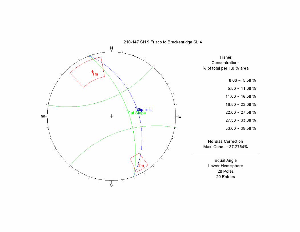
Geologic scan line 4 (SL 4) was situated approximately 400 feet southwest of SL
3 at approximately station 22+00. It was obscured by scree and soil, limiting the
visibility of the orientations of joints and other discontinuities. However, from overall
field observation, SL 4 displays very similar joint characteristics to those measured at
SL 3. A catch ditch will likely be required in this section. Attention to all of these failure
modes will be required during design and construction in this vicinity.

SH 9 SH 9 Dillon Reservoir Alignment Evaluation YA Project No. 210-147 Preliminary Geotechnical Investigation Report Summit County, Colorado
13
Potential rockfall generated from outside of the ROW is possible in this section;
it appears that the velocities and energies would be relatively low, but this has not been
fully evaluated at this time. Proposed rock cut heights in this section were not provided
at the time of this report.
7.0 Subsurface Investigation
7.1 Geotechnical Borings
The general subsurface conditions along the proposed roadway were explored
between September 28, 2010 and October 6, 2006 utilizing a Colorado Department of
Transportation (CDOT) truck mounted CME 75 drill rig and a CDOT rubber tire CME 55
drill rig equipped with HQ size casing and Hollow Stem Auger. See the Site
Investigation Map in Appendix B for boring locations. Engineering Geology Sheets and
Boring logs can be found in Appendix F.
A total of six borings were advanced vertically using HQ size casing while three
borings were drilled vertically in the Fen area using a Hollow Stem Auger. Core
samples were collected, logged, and photographed in the core sample boxes (see
Appendix E, Photographs of Rock Core). Soils samples were collected typically at five-
foot intervals for each boring utilizing a Standard Split Spoon Sampler or a Modified
California Sampler driven by a 140-lb safety hammer with a 30-in stroke, using a
procedure similar to the Standard Penetration Test (ASTM D1586). The number of
blows required driving the Standard Split Spoon Sampler 12 inches after an initial
penetration of 6 inches, or driving the modified California Sampler 12 inches without an
initial penetration of 6 inches, and constitute the N-Value and blow counts as shown on
the Boring Logs. For cohesionless soils, N-Values and blow counts can be correlated
to the relative density of the material. N-Values from 0 to 4 or blow counts from 0 to 5
correspond to very loose materials, N-Values from 4 to 10 or blow counts from 5 to 12
correspond to loose materials, N-Values from 10 to 30 or blow counts from 12 to 35
correspond to medium dense materials, N-Values from 30 to 50 or blow counts from 35
to 60 correspond to dense materials, and N-Values greater than 50 and blow counts
greater than 50 corresponds to very dense materials.

SH 9 SH 9 Dillon Reservoir Alignment Evaluation YA Project No. 210-147 Preliminary Geotechnical Investigation Report Summit County, Colorado
14
Borings YA-1, YA-2 and YA-3 were advanced along SH 9 to explore the
subsurface conditions for the existing SH 9 widening (alternative alignment 1). In
general, the subsurface conditions consisted of 10 to 16 feet of fill described as loose
to medium dense gravels with sand, clay and silt in various mixtures and occasional
cobbles and boulders. In Boring YA-1, organic materials were encountered at depth of
20 to 24 feet overlying glacial till which extended to the end of exploration of 35.3 feet.
In Boring YA-2, bedrock was encountered at depth of 12 feet determined as very hard
quartzite. A 5 foot layer of carbonaceous shale was encountered interbedded at 18 feet
in the quartzite formation. In Boring YA-3, glacial till underlain by fill materials was
encountered at depth of 10 feet and extended to the bottom of boring at 35 feet.
Borings YA-4, YA-5 plus an additional field boring located at the time of
investigation were advanced on either side of SH 9 to explore the biological condition
of the fen. These three biological borings were logged and observed by Dr. Chuck
Schrader of PKM Design Group, Inc.
Borings YA-6, YA-7 and YA-8 were advanced on the west slope to explore the
subsurface condition for the second alignment alternative. Boring YA-6 and YA-7
consisted of respectively 15 feet and 8 feet of very dense sand and gravels overlying
quartzite bedrock to the depth of 30 feet and 27 feet, respectively. The sand and
gravels are described as glacial till in our boring logs and are known as Till of the Bull
Lake glaciations based on USGS findings. Boring YA-8 was drilled at the site of an
artificial berm. The subsurface condition consists of up to 20 feet of fill described as
medium dense clayey sand and gravel overlying glacial till which extended to the end
of boring of 34.7 feet. All the borings except for biological borings are advanced to the
depth of 27 feet to approximately 35 feet. Borings are backfilled and resurfaced with
the drill cuttings.
Groundwater was not encountered in any of these borings at the time of
subsurface exploration. Groundwater conditions in the area will likely vary considerably
throughout the year. Variations can occur during different seasons, following
precipitation events, after construction and site grading, and due to changes in surface
and subsurface drainage characteristics of the surrounding area.

SH 9 SH 9 Dillon Reservoir Alignment Evaluation YA Project No. 210-147 Preliminary Geotechnical Investigation Report Summit County, Colorado
15
7.2 Geophysical Survey
Geophysical surveys were conducted by Yeh and Associates on September 28,
2010 using a seismic tomograph to model the subsurface and bedrock conditions. The
seismic survey was performed to evaluate below ground features and to indicate areas
for potential subsurface exploration within the proposed project site.
Seismic tomography is a methodology for estimating soil and bedrock
properties. Seismic tomography is branch of seismic imaging using shock wave
velocities to estimate density of subsurface materials. Seismic tomography operates
on the principal that vibrations travel faster through hard materials and slower through
soft materials. The process consisted of placing 24 geophones on the ground in a
known array and striking a sledgehammer on the metal plate next to the geophones to
generate a shockwave. The array consisted of two parallel geophones spaced 5 feet
apart, with geophone-to-geophone spacing of 5 feet for a total spread length of 55 feet
Typically 5 to 10 shot records were stacked to provide the final waveform data that was
used to pick first arrivals. Computer modeling of the data allowed real-time results in
the field.
Three geophysical surveys were located in the field approximately along the
proposed cut section on the roadway realignments by pacing from existing site
features. The geophysical survey 1 and 3 were placed on the existing asphalt-paved
bike path and the geophysical survey 2 was placed on the native soils on the west
slope in the vicinity of Boring YA-7. Geophysical survey location is presented on the
Site Investigation Map in Appendix B and 3 tomographs are presented for each array in
Appendix H.
Geophysical survey 1 shows a distinct layer approximately at depth of 9 feet.
The P-wave velocities in the upper layer generally range from 1000 to 5000 feet per
second with several scattered spot with velocity over 6000 feet per second. The P-
wave velocity in the lower layer is generally greater than 5250 feet per second. The
upper layer is likely gravelly sand with cobbles and boulders, and the lower layer is
likely bedrock. This result is consistent with the nearby Boring YA-2.
SH 9 SH 9 Dillon Reservoir Alignment Evaluation YA Project No. 210-147 Preliminary Geotechnical Investigation Report Summit County, Colorado
16
The velocities from survey 2 generally range from 750-2250 feet per second.
This area has some tree growth but appears that some clearing and possibly soil
disturbance may have occurred in the past. No distinct layering appears to exist within
the depth of signal penetration of the energy source (sledge hammer) potentially
because the surface soil is relatively soft which tends to dissipate energy (survey 2 was
placed near Boring YA-7 where the ground surface was covered with vegetation and
pine needles). Generally upper layer P wave velocities below 1550 feet per second
indicate soft, unconsolidated materials such as organic layers and loose disturbed soils
(e.g. some tills display low velocities). The increase in velocity noted with depth is
gradual and locally is related to the presence of large cobbles and boulders. The upper
layer is likely gravelly sand with cobbles and boulders (fill and natural soils) and the
lower layer is likely a similar material with an increase in the number of cobbles and
boulders. This material is identified as till in the boring logs. The data suggest that
bedrock was not encountered within the depth of resolution achievable by the energy
source. The effective depth of the seismic investigation at this location is estimated to
be 8 feet.
For the geophysical survey 3, it is likely that a distinct layer (seen as green in the
tomograph) exists approximately at a depth of 9 feet. The upper layer is likely
colluvium and possibly some till comprising sandy gravel with clusters of cobbles and
boulders. The P-wave velocity for the lower layer (approximately 6000 feet per
second) is likely bedrock.
8.0 Laboratory Testing
A total of 11 soil samples were tested in Yeh and Associates Inc’s laboratory to
determine the classification and engineering characteristics of the on-site soil and rock.
Laboratory tests performed included sieve analysis, Atterberg limits, natural moisture
content, water soluble sulfates, and pH (See Appendix I, Laboratory Test Results).
9.0 Geologic Hazards and Engineering Constraints
Based on our review of the project site it appears that concerns for design and
construction of the proposed widening in this area include loose subsurface materials

SH 9 SH 9 Dillon Reservoir Alignment Evaluation YA Project No. 210-147 Preliminary Geotechnical Investigation Report Summit County, Colorado
17
and potential slope failures in the cut areas and fill areas along the existing SH 9
alignment.
9.1 Loose Subsurface Materials
The existing density of the native sand and gravel material along the
existing SH 9 appears to range from very loose to very dense. In the area of
Boring YA-1, very loose organic sands were encountered at depth of 20 feet. In
the area of Boring YA-3, very loose clayey gravel layer were encountered at
depth of 11 feet (right below the fill layer). These low strength materials in the
soil profile likely result in distress such as cracks, settlement and slides.
Depending on the structure type selected, all foundation alternatives should
address bearing capacity and global stability.
9.2 Landslides
Reconnaissance of the project area revealed a significant cut slope
failure at approximately Sta. 5+00 due to a weak, friable carbonaceous shale
layer which resulted in a combination planar-wedge failure. Further cuts in this
area could pose additional slope concerns. Where the middle shaly layer of the
Upper quartzite member of the Dakota formation is exposed in a critically
oriented cut, for example approximately Sta. 5+00 of the first alternative
alignment, stabilization or mitigation approaches need to be instituted as this
carbonaceous member is weak and disintegrates when exposed. Care needs to
be taken when excavating in this particular area since a cut through this section
steeper than about 24 º (~2.5H:1V) will likely be unstable if this weak shale
bedding layer daylights directly into the cut. Any cuts in this area may require
stabilization, design accommodation or retaining structures to resist potential
slope failure. These options will need to be considered during design and
evaluated during construction.
Although not currently active, portions of the SH 9 embankment has
experienced slope failures along Dillon Reservoir. Failures have occurred near
Sta. 7+50 and 20+10 during periods of heavy precipitation and rapid drawdown

SH 9 SH 9 Dillon Reservoir Alignment Evaluation YA Project No. 210-147 Preliminary Geotechnical Investigation Report Summit County, Colorado
18
of the reservoir. Any proposed retaining walls or expansion of the roadway
embankment in these areas should be evaluated for potential slope instability.
9.3 Soil Corrosivity
Soil samples collected during the subsurface investigation were tested to
determine the water soluble sulfate concentration and pH. The concentration of
water-soluble sulfates in the on-site soils ranges from 0.001 percent to 0.008
percent. The concentration of water-soluble sulfates represents a Class 0
degree of sulfate attack on concrete exposed to these materials. Test results on
acidity of the soil samples indicated pH levels in the range of 8.0 to 8.4. The pH
of the soils at the site indicates the soils are slightly basic and should represent
a negligible degree of pH attack on concrete and metal exposed to these
materials. The degree of attack is based on a range of Class 0 (negligible) to
Class 3 (very severe) as presented in the Colorado Department of
Transportation Standard Specifications for Road and Bridge Construction.
Based on the information, we believe the use of special sulfate and acid
resistant material will not be required for concrete and metal exposed to the on-
site soils.
10.0 Bridge Foundation Recommendations
A new bridge structure is proposed to be constructed to carry the highway over
the fen area. A potential wildlife crossing is also being considered in the study area.
Since the structure selection and the location have not been provided, no exploration
drilling has been conducted to evaluate the subsurface conditions for bridge
foundations. The recommendation provided here is based on the preliminary field
reconnaissance and observation. In general, bridge structures would likely require
deep foundations extended to bedrock due to the loose nature of the subsurface soils.
Design parameters and details for foundation options can be further analyzed once a
final structure selection is provided.

SH 9 SH 9 Dillon Reservoir Alignment Evaluation YA Project No. 210-147 Preliminary Geotechnical Investigation Report Summit County, Colorado
19
11.0 Wall Recommendations
Retaining walls may be expected for either cut or fill slopes throughout the
project limits. No subsurface investigation has been performed for earth retaining
structures at this stage. The recommendations presented below are based on our
reconnaissance of the site and our experience in the area. Further investigation and
evaluation will be completed during the final geotechnical investigation phase.
In general, retaining walls can be placed in two categories: cut slope walls and
fill slope walls. Many of the recommended retaining systems can be applied to either
condition and some systems may be combined to stabilize slopes for unique cases.
The following sections summarize our preliminary recommendations for each of the
proposed wall alternatives.
12.0 Cut Walls
12.1 Ground Nail Walls
This system involves installing reinforcing elements as passive inclusions
in an earth mass to provide stabilization. Although identified as “ground” or “soil”
nails, the system is utilized to stabilize either rock and soil conditions, or a
combination of both.
12.2 Ground Anchor Walls
A ground anchor wall can be used in place of a soil nail wall if excessive
groundwater is present (and where, correspondingly, soil nailing is not effective)
or if additional support is required for cut slope walls, such as areas with
potentially unstable slopes. In the case of ground anchors, it will likely be
necessary to establish depth to bedrock in order to bond the anchor to
substantially increase the load carrying capacity. Ground anchors are a post-
tensioned reinforcement that can be used to minimize slope movement and wall
deformation.

SH 9 SH 9 Dillon Reservoir Alignment Evaluation YA Project No. 210-147 Preliminary Geotechnical Investigation Report Summit County, Colorado
20
13.0 Fill Walls
Fill walls located adjacent to Dillon Reservoir would likely require deep
foundations extended to bedrock due to the loose nature of the subsurface soils and
the effect of groundwater fluctuation caused by the variation in seasonal precipitation.
Changes in the water elevation in Lake Dillon could also create groundwater
fluctuations causing a potential of instability for the proposed fill walls and exsitng
embankment. The instability can be be created during a rapid drawdown condition as
the reservoir water level is dropped during periods of high demand for water
downstream and in Denver. Additional fill wall recommendations are as follows:
13.1 Mechanically Stabilized Earth (MSE) Walls
MSE retaining walls may be feasible for the fill slope retaining structures.
For stability purposes, all MSE walls should be designed with a minimum
embedment of 3 to 5 feet. The reinforcement lengths should be a minimum of 8
feet, 70% of the design height, or the length required to satisfy external stability
requirements, whichever is greater. Global stability is usually the controlling
factor for the design evaluation.
13.2 Cantilever Walls
Cantilever retaining walls may also be feasible for use as either cut or fill
retaining structures. Cantilever walls may be either pre-cast or cast in place
(CIP) and may be placed on shallow foundations or deep foundations. The use
of cantilever walls may require a deep foundation system to transfer the wall
loading either into bedrock or to dense gravels or sands deeper in the soil profile
to avoid bearing capacity and settlement issues. Deep foundations could
consist of driven piles, drilled shafts, or micropiles.
14.0 Site Grading
All site grading should conform to the Colorado Department of Transportation
Standard Specifications for Road and Bridge Construction.

SH 9 SH 9 Dillon Reservoir Alignment Evaluation YA Project No. 210-147 Preliminary Geotechnical Investigation Report Summit County, Colorado
21
14.1 Cut Slopes
The proposed cut slopes in the project limits will encounter a variety of
conditions. All excavations must comply with the applicable local, State, and
Federal safety regulations, and particularly with the excavation standards of the
Occupational Safety and Health Administration (OSHA). The maximum slope
angle for the rock slopes should not exceed 0.5H:1V. Cut slopes in any other
materials should not exceed 1.5H:1V. These values are general and
approximate and require re-evaluation once a final geotechnical investigation
has been performed. Flatter slopes may be required if excavations extend into
the groundwater or the slopes will be exposed for an extended period of time.
Surface water runoff should be directed away from the top of the slope
and should not be allowed to pond at the top or bottom of the slope. Erosion
control may also be an issue in areas with finer grained materials. Steep cut
slopes in the locations of existing slope failures such as at Sta. 5+00 should be
avoided. Stabilization or retaining structures may be required in areas where
potential slope failures may occur due to the presence of water and loose
material.
If excessive water seepage is observed during the excavation, Yeh and
Associates, Inc. should be notified to verify the validity of these
recommendations.
14.2 Fill Slopes
Permanent fill slopes shall be constructed to a maximum slope angle of
2H:1V. Individual areas may be constructed steeper than 2H:1V but must be
evaluated independently and constructed with angular rocky material. Natural
slopes or where grades are 20 percent (5H:1V) or steeper shall be benched
prior to fill placement. The ground surface underlying all fills should be carefully
prepared and new fill properly benched in accordance with the Colorado
Department of Transportation Standard Specifications for Road and Bridge
Construction.

SH 9 SH 9 Dillon Reservoir Alignment Evaluation YA Project No. 210-147 Preliminary Geotechnical Investigation Report Summit County, Colorado
22
Settlement of embankment fill is anticipated during and after construction
of the embankment fill. As the source of the fill material which will make up the
majority of the embankment is unknown, a further evaluation for the settlement
will be completed when the final design and the fill materials are identified.
It is our understanding that proposed slopes in the project area will have
an approximate 2H:1V slope to 3H:1V slope. We believe the proposed slopes
should remain stable with proper construction. Surface water runoff should be
directed away from the top of the slope and should not be allowed to pond at the
top or bottom of the slope.
Changes in the water elevation in Lake Dillon could create groundwater
fluctuations with the potential for instability of the fill slopes during a rapid
drawdown of a high-water condition of the reservoir if the fill material does not
drain freely. Additional evaluation of the embankment stability will be required
once the final configuration is determined.
15.0 Surface Drainage
Positive drainage should be provided during construction and maintained
throughout the life of the proposed structures. Surface runoff and infiltration of water
into subgrade materials must be prevented during construction. Surface features that
could retain water in areas adjacent to the paving should be sealed or eliminated. Any
permanent drainage swale adjacent to the paving must be properly graded and
established for prevention of ponding of water on or immediately adjacent to pavement
areas. Concentrated runoff should be avoided in areas susceptible to erosion and
slope instability.
16.0 Comparison of Alignment Alternatives
The first alternative follows the current SH 9 alignment along Dillon Reservoir.
This alignment would require cut slope development in hard rock which would entail
significant blasting (Sta. 5+00 through approximately Sta. 30+00). Fill slopes along the
reservoir margin in this same area appear to encroach on the reservoir and require
retaining walls in some locations. Changes in the water elevation in Lake Dillon could
SH 9 SH 9 Dillon Reservoir Alignment Evaluation YA Project No. 210-147 Preliminary Geotechnical Investigation Report Summit County, Colorado
23
create groundwater fluctuations with the potential for instability of the fill slopes during a
rapid drawdown condition of the reservoir if the fill does not drain freely. In addition the
cut in the vicinity of Sta. 5+00 would require laying back the slope in the immediate
area at about 2.5H:1V or alternatively some other form of stabilization.
Fill walls located adjacent to Dillon Reservoir would likely require deep
foundations extended to bedrock due to the loose nature of the subsurface soils and
the effect of groundwater fluctuation caused by changes in the water elevation. As
indicated previously groundwater fluctuation could potentially create instability of the
walls during a rapid drawdown condition of the reservoir if the backfill does not drain
freely. This can be accommodated by addressing this during design of the walls.
The second alternative (Iron Springs) runs from Farmer's Corner to Frisco and
follows the existing bike path for a portion of the alignment. This alignment occurs
mostly in glacial till and generally can be excavated using conventional methods,
though in places, hard to very hard bedrock may be encountered which would likely
require blasting. Based on the preliminary findings, soil cuts in this area can be
constructed at a 2H:1V provided that ground water is not encountered and surfical
erosion is controlled. This alignment has been potentially identified for a wildlife
crossing at approximately Sta. 25+00. It is anticipated that the crossing will be a
vegetated concrete structure constructed over the highway. Depth to bedrock is not
available at this location since drilling did not intersect bedrock because of thick fill
used to construct a disused impoundment in the immediate area. The material
encountered in the subsurface investigation generally consists of glacial till overlying
bedrock. The estimated depth to bedrock is about 35-40 feet at approximately Sta.
25+00, discounting the thickness of the abandoned impoundment berm. Depth to
bedrock should be determined in the final geotechnical investigation.
Based on the information obtained during the preliminary site investigation the
Iron Springs alternative alignment should be less difficult to design and construct from
a geotechnical perspective than following the current Dillon Reservoir alignment. The
following table (Table 1) summarizes the geotechnical conditions encountered on each
alignment.

SH 9 SH 9 Dillon Reservoir Alignment Evaluation YA Project No. 210-147 Preliminary Geotechnical Investigation Report Summit County, Colorado
24
Table 1. Summary of geotechnical issues along the SH 9 alignments.
Geotechnical Condition Lake Dillon Alignment Iron Springs Alignment
Cut slope stability Issue: Existing cut slope at Sta. 5+00 has experienced a previous slope failure Mitigation: Layback slope and remove slide, buttress and/or ground anchors
Issue: No existing slope failures observed Mitigation: 2H:1V cut slopes would likely be adequate
Fill Slope Stability Issue: Existing fill slopes at Sta. 7+50 and 20+10 have experienced previous slope failures Mitigation: Avoidance, light weight fill of ground improvements
Issue: No existing slope failures observed Mitigation: 2H:1V to 3H: 1V fill slopes would likely be adequate
Retaining walls Issue: Existing fill slopes at Sta. 7+50 and 20+10 have experienced previous slope failures Mitigation: Avoidance (shift alignment to the cut), light weight fill of ground improvements
Issue: Retaining walls not required Mitigation: N/A
Groundwater Issue: Rapid down draw in Dillon Reservoir may have a detrimental effect of stability Mitigation: Avoidance (shift alignment to the cut), light weight fill of ground improvements
Issue: Although not encountered in the site investigation, the presence of Iron Springs could be an indication that shallow ground water, seeps and springs may be present along alignment. Mitigation: Avoidance, horizontal and cut-off drains.

SH 9 SH 9 Dillon Reservoir Alignment Evaluation YA Project No. 210-147 Preliminary Geotechnical Investigation Report Summit County, Colorado
25
17.0 Limitations
This study has been conducted in accordance with generally accepted
geotechnical engineering practices in this area for use by the client for design
purposes. The conclusions and recommendations submitted in this report are based
upon the data obtained from exploratory borings and field reconnaissance. The nature
and extent of subsurface variations across the site may not become evident until
excavation is performed. We recommend on-site observation of excavations and
foundation bearing strata by a representative of the geotechnical engineer.
Respectfully Submitted,
Yeh and Associates, Inc.
Prepared by: Reviewed by:
___________________ ___________________
I-Ping Chen Howard Hume, Ph. D, P.G.
Staff Engineer Senior Project Manager
Enc: 6 copies

SH 9 SH 9 Dillon Reservoir Alignment Evaluation YA Project No. 210-147 Preliminary Geotechnical Investigation Report Summit County, Colorado
26
18.0 References
1. Kellogg, Karl S., et al., 2002, Geologic Map of the Frisco Quadrangle, Summit
County, Colorado: Scale 1:24,000

27
APPENDIXA‐ProjectLocationMap

Figure A-1. Project Location Map
Colorado
I-70
I-25
SH 9
Dillon Reservoir

28
APPENDIXB‐SiteInvestigationMap

Phone:303-512-5600 FAX:303-512-5675
Colorado Department of Transportation
Dumont, CO 80436
Region 1
Mountain Residency P.O. Box 399
WDSX-XX-XX
X-XX-XX
Numbers
Structure
No Revisions:
Revised:
Void: Sheet Subset:
Detailer:
Designer:
_____
G. Anderson
G. Anderson________
________
Sheet NumberSubset Sheets: 1 of X
Init.CommentsDate:
R-X
Sheet Revisions As Constructed
XXX
8/13/2010Print Date:
Horiz. Scale:1:400
IRON SPRINGS OVERVIEW.dgn
Vert. Scale: As Noted
Unit Leader Initials
Project No./CodeFile Name:
Unit Information
POTENTIAL ALIGNMENT
andersong 9:1
5:4
0
AM
C:\
Projects\sh 9\
Desig
n\
Dra
win
gs\IR
ON
SP
RIN
GS
OV
ER
VIE
W.d
gn
400’0’ 200’ 800’
EXISTING BIKE PATH
DILLON RESERVOIR
EIS ALIGNMENT AT LESLIE’S CURVE
POTENTIAL "IRON SPRINGS"
ALIGNMENT AT LESLIE’S CURVE
POTENTIAL BRIDGE OVER FEN
ELEC
ELEC
ELEC
ELEC
ELEC
ELEC
0+00
5+00
10+00
15+00
20+00
25+00
30
+00
35
+00
40
+00
45+00
50+00
55+00
60
+00
PO
B 0
+00.0
0
PC
4+88.5
7
PT 10
+35.7
1
PC 22+26.4
6
PT 31+83.3
9
PC 39+86.7
6
PT 44+23.78
PC 55+35.84
PT 60
+22.7
8
PI 7
+74.6
7
PI 27
+80.5
4
PI 4
2+11.5
3
PI 5
7+88.0
4
0+00
5+00
10+00
15+0
0
20+00
25+00
30
+00
35+00
40+00
45+00
50+00
55+00
60+00
62+38
POB 0+00.00
PC 12+66.89
PT 17
+27.13
PC 23+91.9
4
PT 26+31.0
9
PC 28
+33.4
0
PT 41+45.37
POE 62+38.46
PI 15
+04.3
5
PI 2
5+12.2
2
9030
9030
9030
9030
9030
9040
9040
9040
9040
9040
9040
9040
9040
9040
9040
9040
9040
9050
9040
9040
9040
9040
9050
9090
910
0
910
0
9110
9110
912
0
912
0
9120
9120
913
0
913
0
913
0
9130
9130
913
0
9130
914
0
914
0

29
APPENDIXC‐GeologyMapandLegend


30
APPENDIXD‐SeismicDesignSpectra


31
APPENDIXE‐ExistingRockcutEvaluation


32
APPENDIXF‐EngineeringGeologySheetsandBoringLogs

Consulting Engineers & Scientists
Yeh and Associates, Inc. Numbers
Structure
No Revisions:
Revised:
Void: Sheet Subset:
Detailer:
Designer:
M. WALZ
H. HUME
Project Number
Sheet NumberSubset Sheets:
Init.CommentsDate:
R-X
Sheet Revisions As Constructed Project No./Code
9020
9030
9040
9050
8970
8980
8990
9000
9010
11/30/2010Print Date:
Horiz. Scale:1:10
210-147 Engineering Geology01.dgn
Vert. Scale: As Noted
Unit Leader Initials
File Name:
Unit Information
ENGINEERING GEOLOGY
Mik
e
Walz 1:2
7:1
5
PM
W:\
2010
Projects\
210-14
7
SH 9
Fris
co to
Breckenrid
ge\
Dw
g\
210-14
7
Engin
eerin
g
Geolo
gy01.d
gn
YA-1YA-2
YA-3
Phone:303-512-5600 FAX:303-512-5675
Colorado Department of Transportation
Region 1
Moutain Residency P.O. Box 399
WDS
Dumont, CO 80436
9020
9030
9040
9050
8970
8980
8990
9000
9010
AsphaltFill with Gravel
as major soil
Glacial Till
Boring No.
RQD
x
x
x
Graphic material description
Lab test results
Ground WaterPenetration Resistance
(Blows per foot or
inches of penetration)
LEGEND
TYPICAL TEST HOLE LOG
Note:
Surface elevations are approximate
borings were not surveyed
RQDRQD
RQD0
0
0
0
9
0
26
20
22
4
35
41
50:4"
MC= 5.3 %#200= 3 %LL= NVPL= NPPI= NPAASHTO: A-1-a (0)USCS: GP
MC= 31.8 %#200= 42 %LL= 34PL= 17PI= 17AASHTO: A - 6 (3)USCS: SC
0
0
25
13
10
25
17
16
50:1"
MC= 9.2 %DD= 128.1 pcf#200= 13 %LL= NVPL= NPPI= NPpH= 8.2S= 0.003 %AASHTO: A-1-b (0)USCS: GM
pH= 8.4S= 0.008 %
0
0
10
0
52
8
10
11
3
50:1"
26
38
MC= 11.6 %#200= 15 %LL= 38PL= 12PI= 26AASHTO: A-2-6 (0)USCS: GCMC= 5.5 %#200= 3 %LL= NVPL= NPPI= NPpH= 8S= 0.001 %AASHTO: A-1-a (0)USCS: GP
ShaleUSCS Clayey
Sand
Bedrock-Quartzite
Code

RQD
RQD
Consulting Engineers & Scientists
Yeh and Associates, Inc. Numbers
Structure
No Revisions:
Revised:
Void: Sheet Subset:
Detailer:
Designer:
M. WALZ
H. HUMECode
Project Number
Sheet NumberSubset Sheets:
Init.CommentsDate:
R-X
Sheet Revisions As Constructed Project No./Code
9080
9090
9100
9110
9030
9040
9050
9060
9070
11/30/2010Print Date:
Horiz. Scale:1:10
210-147 Engineering Geology02.dgn
Vert. Scale: As Noted
Unit Leader Initials
File Name:
Unit Information
ENGINEERING GEOLOGY
Mik
e
Walz 1:2
6:5
7
PM
W:\
2010
Projects\
210-14
7
SH 9
Fris
co to
Breckenrid
ge\
Dw
g\
210-14
7
Engin
eerin
g
Geolo
gy02.d
gn
YA-6
YA-7
YA-8
Phone:303-512-5600 FAX:303-512-5675
Colorado Department of Transportation
Region 1
Moutain Residency P.O. Box 399
WDS
Dumont, CO 80436
Fill with Gravel
as major soilGlacial Till
Boring No.
RQD
x
x
x
Graphic material description
Lab test results
Ground WaterPenetration Resistance
(Blows per foot or
inches of penetration)
LEGEND
TYPICAL TEST HOLE LOG
9080
9090
9100
9110
9030
9040
9050
9060
9070
Note:
Surface elevations are approximate
borings were not surveyed
33
79
6
60
63
58
RQD
80:11"MC= 10.7 %
#200= 21 %
AASHTO: A-1-b (0)
USCS: SM
MC= 2.5 %
#200= 24 %
AASHTO: A-1-b (0)
USCS: SM
0
35
65
58
41
97:11" MC= 7.3 %
#200= 14 %
LL= NV
PL= NP
PI= NP
pH= 8.1
S= 0.002 %
AASHTO: A-1-a (0)
USCS: SM
8
0
0
11
10
20
19
64
50:2"
MC= 10.9 %
#200= 32 %
LL= 30
PL= 9
PI= 21
pH= 8.3
S= 0.001 %
AASHTO: A-2-6 (1)
USCS: SC
MC= 7.9 %
#200= 12 %
LL= NV
PL= NPPI= NP
AASHTO: A-1-a (0)
USCS: GM
Bedrock-Quartzite

12/12/14
8/9/11
9/13/9
2/2/2
3/11/24
25/20/21
50:4"
0.0 - 1.0 ft. ASPHALT, no.1.0 - 16.0 ft. FILL GRAVEL with sand, cobblesand boulders, tan to gray - brown, medium dense,thin layers of clay.
16.0 - 24.0 ft. clayey SAND, medium plasticity,very loose.
At 20-24 ft. with organic black material.
24.0 - 35.3 ft. GRAVEL with sand, boulders andcobbles, tan to gray - brown, dense to very dense,Glacial Till.
Bottom of Hole at 35.3 ft.
0
0
0
0
9
0
8
22
0
14
36
17
MC= 5.3 %#200= 3 %LL= NVPL= NPPI= NPAASHTO: A-1-a (0)USCS: GP
MC= 31.8 %#200= 42 %LL= 34PL= 17PI= 17AASHTO: A - 6 (3)USCS: SC
26
20
22
4
35
41
50:4"
Boring Began: 10/4/2010
Drilling Method: Coring
Drill: CME 75
Driller: CDOT - Dave
Logged By: I. Ksouri
Final By: M. Norris
Inclination: Vertical
Completed: 10/4/2010Drill Bit:Casing:Weather:
Ground Water Notes: Not encountered during drilling
DepthDateTime
Total Depth: 35.3 ftGround Elevation:Location:Coordinates: N: E:
---
---
---
---
Soil Samples
Field Notesand
Lab Tests
10
20
30
N
Project: SH 9 Frisco to Breckenridge
Material Description
Lith
olog
y
Rock
GEOTECHNICAL ENGINEERING CONSULTANTS
RQ
D
Rec
over
y (%
)
Blowsper6 in
YEH AND ASSOCIATES, INC.
Run
/ S
ampl
e Ty
pe
Dep
th(fe
et)
Ele
vatio
n(fe
et)
Boring: YA-1Project Number: 210-147 Date: Sheet 1 of 1
BO
RIN
G L
OG
CO
PY
OF
210-
147
FRIS
CO
TO
BR
EC
K.G
PJ
YE
H A
SS
OC
IATE
S.G
DT
11/
29/1
0

8/9
5/11
50:1"
0.0 - 12.0 ft. FILL GRAVEL with silt, sand, cobblesand boulders, tan to gray - brown, no plasticity,medium dense, thin layers of clay.
12.0 - 18.0 ft. QUARTZITE, light brown to lightgray, very hard, highly fractured in all directions, ironstains at joints.
18.0 - 23.0 ft. CARBONACEOUS SHALE, black.
23.0 - 30.0 ft. QUARTZITE, light brown to lightgray, very hard.
Bottom of Hole at 30.0 ft.
0
0
25
14
10
25
28
25
81
98
98
50
MC= 9.2 %DD= 128.1 pcf#200= 13 %LL= NVPL= NPPI= NPpH= 8.2S= 0.003 %AASHTO: A-1-b (0)USCS: GM
pH= 8.4S= 0.008 %
17
16
50:1"
Boring Began: 9/29/2010
Drilling Method: Coring
Drill: CME 55
Driller: CDOT - Dave
Logged By: I. Ksouri
Final By: M. Norris
Inclination: Vertical
Completed: 9/29/2010Drill Bit:Casing:Weather:
Ground Water Notes: Not encountered during drilling
DepthDateTime
Total Depth: 30.0 ftGround Elevation:Location:Coordinates: N: E:
---
---
---
---
Soil Samples
Field Notesand
Lab Tests
10
20
30
N
Project: SH 9 Frisco to Breckenridge
Material Description
Lith
olog
y
Rock
GEOTECHNICAL ENGINEERING CONSULTANTS
RQ
D
Rec
over
y (%
)
Blowsper6 in
YEH AND ASSOCIATES, INC.
Run
/ S
ampl
e Ty
pe
Dep
th(fe
et)
Ele
vatio
n(fe
et)
Boring: YA-2Project Number: 210-147 Date: Sheet 1 of 1
BO
RIN
G L
OG
CO
PY
OF
210-
147
FRIS
CO
TO
BR
EC
K.G
PJ
YE
H A
SS
OC
IATE
S.G
DT
11/
29/1
0

3/8
1/2
50:1"
4/22
2/36
0.0 - 10.0 ft. FILL GRAVEL with sand, cobblesand boulders, tan to gray - brown, medium plasticity,loose, thin layers of clay.
10.0 - 35.0 ft. clayey GRAVEL poorly graded, withcobbles and boulders, tan to gray - brown, noplasticity, very loose to very dense, some clay,Glacial Till.
Bottom of Hole at 35.0 ft.
0
0
11
0
52
8
11
17
15
50
90
100
80
63
MC= 11.6 %#200= 15 %LL= 38PL= 12PI= 26AASHTO: A-2-6 (0)USCS: GCMC= 5.5 %#200= 3 %LL= NVPL= NPPI= NPpH= 8S= 0.001 %AASHTO: A-1-a (0)USCS: GP
11
3
50:1"
26
38
Boring Began: 9/30/2010
Drilling Method: Coring
Drill: CME 75
Driller: CDOT - Dave
Logged By: I. Ksouri
Final By: M. Norris
Inclination: Vertical
Completed: 9/30/2010Drill Bit:Casing:Weather:
Ground Water Notes: Not encountered during drilling
DepthDateTime
Total Depth: 35.0 ftGround Elevation:Location:Coordinates: N: E:
---
---
---
---
Soil Samples
Field Notesand
Lab Tests
10
20
30
N
Project: SH 9 Frisco to Breckenridge
Material Description
Lith
olog
y
Rock
GEOTECHNICAL ENGINEERING CONSULTANTS
RQ
D
Rec
over
y (%
)
Blowsper6 in
YEH AND ASSOCIATES, INC.
Run
/ S
ampl
e Ty
pe
Dep
th(fe
et)
Ele
vatio
n(fe
et)
Boring: YA-3Project Number: 210-147 Date: Sheet 1 of 1
BO
RIN
G L
OG
CO
PY
OF
210-
147
FRIS
CO
TO
BR
EC
K.G
PJ
YE
H A
SS
OC
IATE
S.G
DT
11/
29/1
0

80:11"
0.0 - 15.0 ft. silty SAND with gravels, cobbles andboulders, tan to gray, no plasticity, very dense, thinlayers of clay, Glacial Till.
15.0 - 30.0 ft. QUARTZITE, light brown to lightgray, very hard, iron stains at the joints.
Bottom of Hole at 30.0 ft.
33
79
7
60
63
58
72
100
32
83
83
92
MC= 10.7 %#200= 21 %AASHTO: A-1-b (0)USCS: SM
MC= 2.5 %#200= 24 %AASHTO: A-1-b (0)USCS: SM
80:11"
Boring Began: 10/6/2010
Drilling Method: Coring
Drill: CME 55
Driller: CDOT - Dave
Logged By: I. Ksouri
Final By: M. Norris
Inclination: Vertical
Completed: 10/6/2010Drill Bit:Casing:Weather:
Ground Water Notes: Not encountered during drilling
DepthDateTime
Total Depth: 30.0 ftGround Elevation:Location:Coordinates: N: E:
---
---
---
---
Soil Samples
Field Notesand
Lab Tests
10
20
30
N
Project: SH 9 Frisco to Breckenridge
Material Description
Lith
olog
y
Rock
GEOTECHNICAL ENGINEERING CONSULTANTS
RQ
D
Rec
over
y (%
)
Blowsper6 in
YEH AND ASSOCIATES, INC.
Run
/ S
ampl
e Ty
pe
Dep
th(fe
et)
Ele
vatio
n(fe
et)
Boring: YA-6Project Number: 210-147 Date: Sheet 1 of 1
BO
RIN
G L
OG
CO
PY
OF
210-
147
FRIS
CO
TO
BR
EC
K.G
PJ
YE
H A
SS
OC
IATE
S.G
DT
11/
29/1
0

32/97:11"
0.0 - 8.0 ft. silty SAND with gravels, cobbles andboulders, tan to gray - brown, no plasticity, verydense, layers of clay, Glacial Till.
8.0 - 27.0 ft. QUARTZITE, light brown to light gray,iron stains at the joints, highly fractured in alldirections.
Bottom of Hole at 27.0 ft.
0
36
65
58
42
27
93
100
100
100
MC= 7.3 %#200= 14 %LL= NVPL= NPPI= NPpH= 8.1S= 0.002 %AASHTO: A-1-a (0)USCS: SM
97:11"
Boring Began: 10/5/2010
Drilling Method: Coring
Drill: CME 55
Driller: CDOT - Dave
Logged By: I. Ksouri
Final By: M. Norris
Inclination: Vertical
Completed: 10/5/2010Drill Bit:Casing:Weather:
Ground Water Notes: Not encountered during drilling
DepthDateTime
Total Depth: 27.0 ftGround Elevation:Location:Coordinates: N: E:
---
---
---
---
Soil Samples
Field Notesand
Lab Tests
10
20
30
N
Project: SH 9 Frisco to Breckenridge
Material Description
Lith
olog
y
Rock
GEOTECHNICAL ENGINEERING CONSULTANTS
RQ
D
Rec
over
y (%
)
Blowsper6 in
YEH AND ASSOCIATES, INC.
Run
/ S
ampl
e Ty
pe
Dep
th(fe
et)
Ele
vatio
n(fe
et)
Boring: YA-7Project Number: 210-147 Date: Sheet 1 of 1
BO
RIN
G L
OG
CO
PY
OF
210-
147
FRIS
CO
TO
BR
EC
K.G
PJ
YE
H A
SS
OC
IATE
S.G
DT
11/
29/1
0

6/6/14
6/8/11
30/32/32
32/50:2"
0.0 - 20.0 ft. clayey SAND with gravels, cobblesand boulders, tan to brown-gray, no plasticity,medium dense.
20.0 - 34.7 ft. silty GRAVEL with sand, cobblesand boulders, tan to brown-gray, no plasticity, verydense, Glacial Till.
Bottom of Hole at 34.7 ft.
8
0
0
11
11
13
49
32
56
52
MC= 10.9 %#200= 32 %LL= 30PL= 9PI= 21pH= 8.3S= 0.001 %AASHTO: A-2-6 (1)USCS: SC
MC= 7.9 %#200= 12 %LL= NVPL= NPPI= NPAASHTO: A-1-a (0)USCS: GM
20
19
64
50:2"
Boring Began: 10/5/2010
Drilling Method: Coring
Drill: CME 55
Driller: CDOT - Dave
Logged By: I. Ksouri
Final By: M. Norris
Inclination: Vertical
Completed: 10/5/2010Drill Bit:Casing:Weather:
Ground Water Notes: Not encountered during drilling
DepthDateTime
Total Depth: 34.7 ftGround Elevation:Location:Coordinates: N: E:
---
---
---
---
Soil Samples
Field Notesand
Lab Tests
10
20
30
N
Project: SH 9 Frisco to Breckenridge
Material Description
Lith
olog
y
Rock
GEOTECHNICAL ENGINEERING CONSULTANTS
RQ
D
Rec
over
y (%
)
Blowsper6 in
YEH AND ASSOCIATES, INC.
Run
/ S
ampl
e Ty
pe
Dep
th(fe
et)
Ele
vatio
n(fe
et)
Boring: YA-8Project Number: 210-147 Date: Sheet 1 of 1
BO
RIN
G L
OG
CO
PY
OF
210-
147
FRIS
CO
TO
BR
EC
K.G
PJ
YE
H A
SS
OC
IATE
S.G
DT
11/
29/1
0

33
APPENDIXG‐PhotographsofRockCore

Boring YA‐2 Depth 0‐20 ft
Boring YA‐2
Depth 20‐30 ft
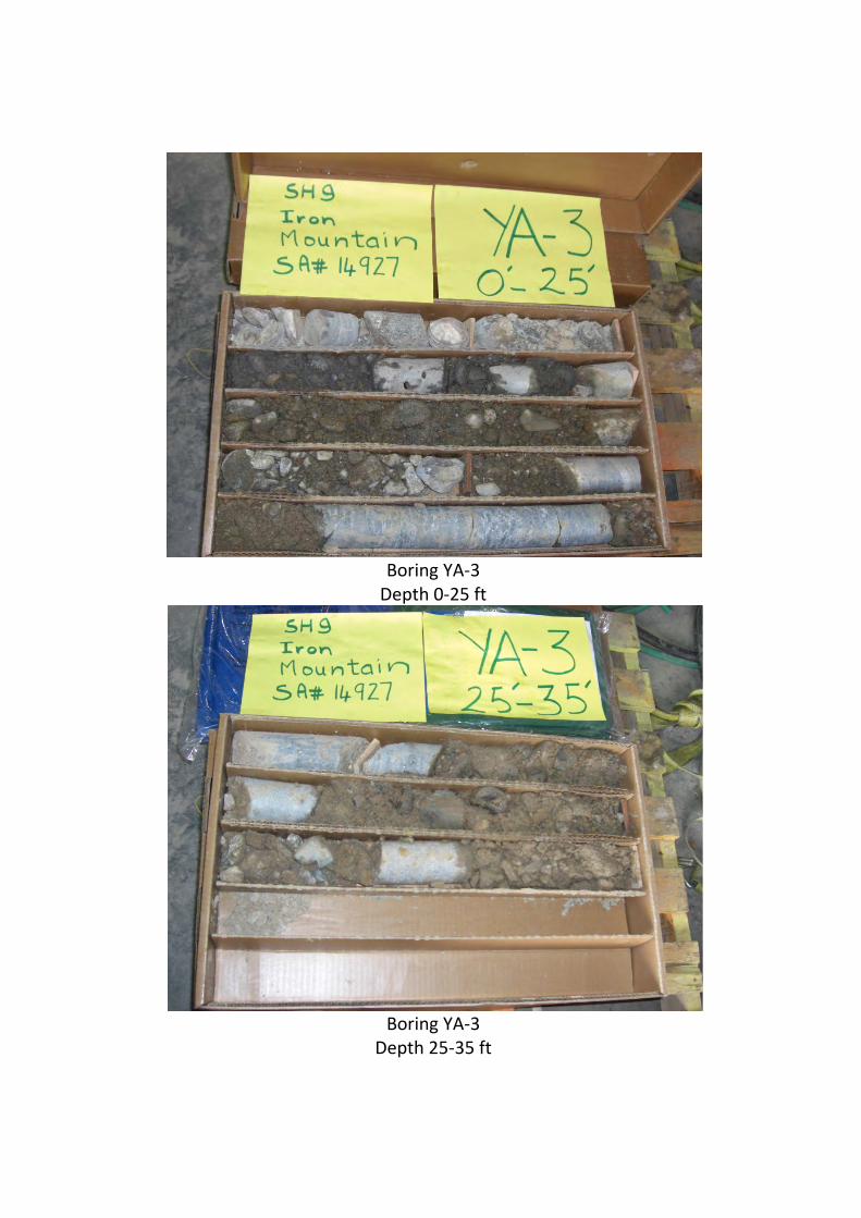
Boring YA‐3Depth 0‐25 ft
Boring YA‐3
Depth 25‐35 ft
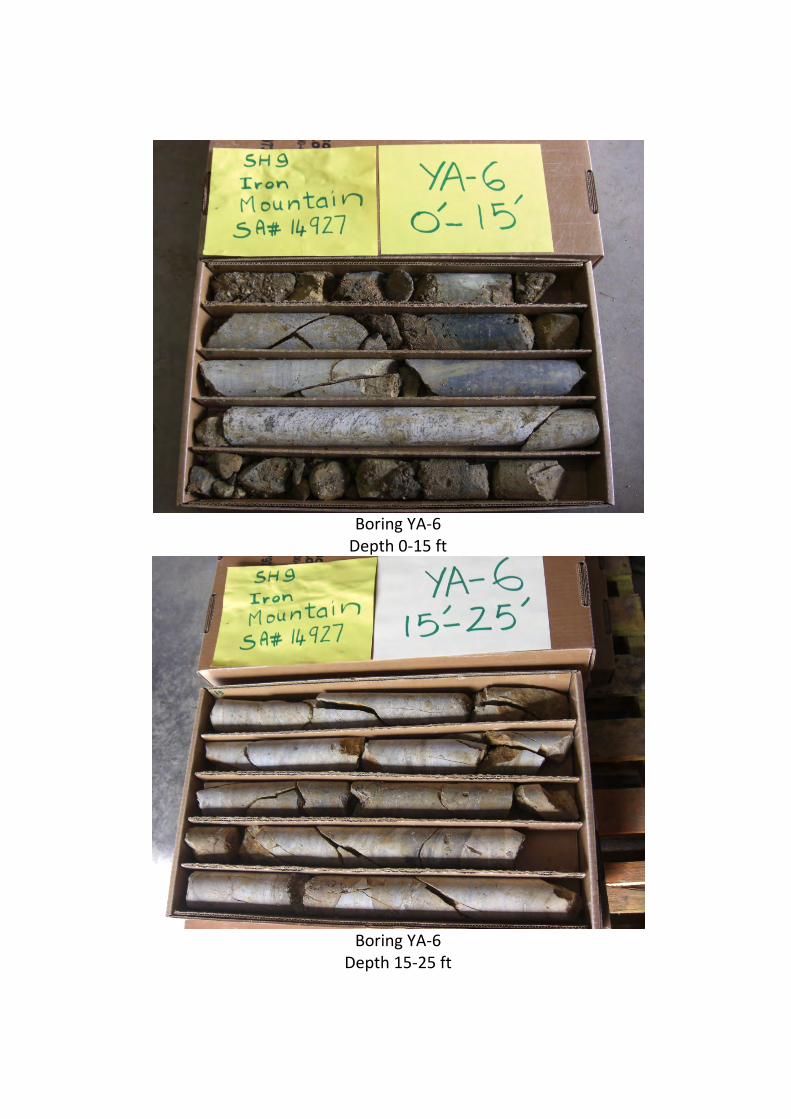
Boring YA‐6Depth 0‐15 ft
Boring YA‐6
Depth 15‐25 ft
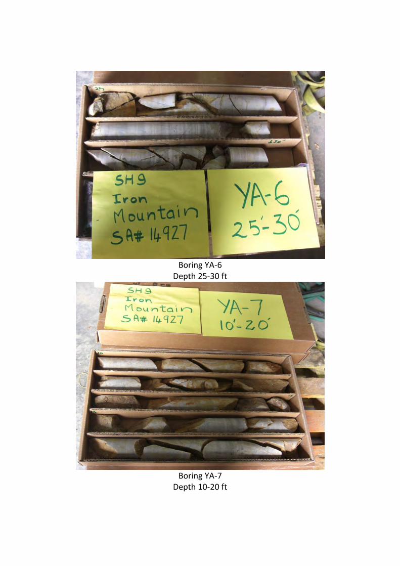
Boring YA‐6
Depth 25‐30 ft
Boring YA‐7
Depth 10‐20 ft

Boring YA‐7
Depth 20‐27 ft

34
APPENDIXH‐Tomographs
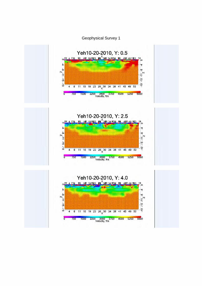
Geophysical Survey 1

Geophysical Survey 2
Geophysical Survey 2

Geophysical Survey 3

35
APPENDIXI‐LaboratoryTestResults

YEH & ASSOCIATES, INC
Summary of Laboratory Test Results
Project No: Date: 11/10/2010
Gradation Atterberg Unconf.Comp.
Strength
(psf)
210 - 147 Project Name:
Sample Location
Sample Type
Natural Dry Density
(pcf)
Natural Moisture Content
(%)PL
USCSAASHTOPI
Water Soluble Sulfate
%
R-VALUE% Swell (+) /
Consoli- dation (-)
pH
SH 9 Frisco to Breckenridge
CLASSIFICATION
Sand (%)
Fines < #200 (%)
LLBoring NO.
Depth (ft)Gravel > #4 (%) (psf)
YA - 1 15-16.5 SS 5.3_
75 22 3 NV NP NP_ _ _ _ _
A-1-a ( 0 ) GP
YA - 1 23-25 Grab 31.8_
17 41 42 34 17 17_ _ _ _ _
A - 6 ( 3 ) SC
YA - 2 10-11 CA 9.2 128.1 47 40 13 NV NP NP 8.2 0.003_ _ _
A-1-b ( 0 ) GM
(%) %(%)(%)
( )
YA - 2 23-24 Core_ _ _ _ _ _ _ _
8.4 0.008_ _ _ _ _
YA - 3 10-11 Core 11.6_
61 24 15 38 12 26_ _ _ _ _
A-2-6 ( 0 ) GC
YA - 3 15-17 Core 5.5_
69 28 3 NV NP NP 8.0 0.001_ _ _
A-1-a ( 0 ) GP( )
YA - 6 4 Core 10.7_
36 43 21_ _ _ _ _ _ _ _
A-1-b ( 0 ) SM
YA - 6 12 Core 2.5_
30 46 24_ _ _ _ _ _ _ _
A-1-b ( 0 ) SM
YA - 7 5-6.5 SS 7.3_
39 47 14 NV NP NP 8.1 0.002_ _ _
A-1-a ( 0 ) SM( )
YA - 8 15-16.5 SS 10.9_
7 61 32 30 9 21 8.3 <0.001_ _ _
A-2-6 ( 1 ) SC
YA - 8 25-26.5 SS 7.9_
49 39 12 NV NP NP_ _ _ _ _
A-1-a ( 0 ) GM
Rev 2 - 8/02 Page 1 of 1


