precise calibration of tuning forks · 2017-11-03 · 228 philips technical review vol. 12, no. 8...
TRANSCRIPT

228 PHILIPS TECHNICAL REVIEW VOL. 12, No. 8
PRECISE CALIBRATION OF TUNING FORKS
by C. C. J. ADDINK. 681.831.3 :534.321.71 :534.63
The introduction into the field of music of the new international standard of concert pitchbased on a frequency of 440 els for the 110teA3 in the middle octave instead of 435 cis still involvesdifficulties owing to the lack of good standards, the tuning forks used in practice leaving muchto be desired. Hence the greater interest now being shown in accurately calibrated tuning forks.
An international conference held in London in1939 recommended that such bodies as the "ComitéConsultatif International Téléphonique", the "In-ternational Electrotechnical Commission" and the"Union Internationale de Radiodiffusion", asalso the various national standardisation commit-tees, should fix the concert pitch at a frequency of440 els for the note A3 of the middle octave - in-stead of the 435 els internationally accepted atVienna in 1885 - and that this should be adheredto as closely as possible in all musical performancesI).In practice the usual tuning forks are, it is true,
1) See, e.g., Internationale Ncufestsetzung des Stirnmtones,Akustische Zeitschrift 4, 288, 1939.
tuned higher than 435 els but often differ, in thepositive or the negative sense, several els from thefigure of 440 els. Since there was no standardfor the frequency of 440 els in this laboratory amethod has been developed, as the first step inthis direction. for measuring audio frequenciesdirect (i.e. by counting the number of oscillationsin a time interval) and with extreme accuracy.With the aid of an apparatus working accordingto this method not only have tuning forks of 440 elsbeen calibrated but also sets of 13 tuning forks,forming a tempered chromatic scale of one octave(fig. I) .The methodreferred to will be described here,but the question to be considered first is the degreeof accuracy to be demanded from a tuning fork.
Fig. 1. Set of 13 tuning forks made in the Phi1ips Laboratory. Together they form a tem-pered chromatic scale from Cl to c2, with al = 440 els. The reason for the cylindrical shapeis explained in the last paragraph.

FEBRUARY 1951 CALIBRATION OF TUNING FORKS 229
Accuracy required of a tuning fork
The useful decay time of a normal tuning forkis 5 to 15 seconds. When the pitch of a musicalinstrument is compared with the tuning fork inthe normal way one can usually hear beats. If,however, the difference in frequency is so smallthat there are no more than two or three beatsduring the decay time then they are hardly notice-able as such and one has reached, the limit of theaccuracy of the tuning fork. It serves no purpose,therefore, to require any greater precision than0.2 cIs (one beat in 5 seconds), or in other wordsthe frequency of the tuning fork has to lie betweenthe limits of 439.8 and 440.2 cIs 2). (This degreeof accuracy is obviously only required for musicalinstruments with a fixed tuning, such as the organ,the piano, the harp, etc.) The frequency, however,has to be determined with greater accuracy,because one must be quite sure of the last decimalin the said limits. The permissible measuring erroris therefore 0.05 cle,which at a frequency of 440 cIsamounts to a measuring accuracy of about 0.01%.This implies that account must be taken of the
temperature when measuring and when using thetuning fork in practice. The temperature coefficientof the frequency in the case of a steel tuning forkis in the order of -1 X 10⁻⁴per oe, while for the forksmade of a hard aluminium alloy îllustrated in fig. 1it is about -2.5 X 10⁻⁴ per oe.Method of measuring
As is evident from the foregoing, for calibratinga tuning fork a more accurate method is neededthan that where the tuning fork is compared witha standard frequency byear. Furthermore, withfrequency differences less than 0.1% the sign ofthe error can no longer be determined by car.
The method of calibrating worked out by usbriefly amounts to the following. The frequency ofan auxiliary oscillator is matched with that of thetuning fork to be calibrated and then a synchronousclock is connected to the oscillator and the oscilla-tions made by the auxiliary oscillator in a certaininterval of time are counted. This time interval ismeasured with the aid of a calibrated pendulumtimepiece.
Matching the auxiliary oscillator
Owing to the damped character of the vibrationa tuning fork is not suitable for measuring the
2) Other authors arrive at the same tolerance another way:H. J. von Braunmühl and O. Schubert Ein neuerelektrischer Stimmtongeher für 440 Hz' AkustischeZeitschrift 6, 299-303, 1941. '
frequency with sufficient accuracy without someother aids. It is true that a tuning fork can be keptin vibration by electrical means, but then, unlessa great deal of care is taken, the frequency at whichit vibrates differs somewhat from the frequencyof a fork vibrating freely, and it is just this freevibration that has to be measured accurately.What is needed for calibrating, therefore, is anauxiliary oscillator which, once it has been matchedwith the freely vibrating fork, continues to oscillatein that frequency for an unlimited length of time.
An RC oscillator consisting only of resistors,capacitors and amplifying valves is very suitablefor this purpose. If such an oscillator is properlydesigned, when it has reached temperature equili-brium the relative frequency change in the audio-frequency range can be kept smaller than 1:1053).The matching of the frequency of the oscillator
with that of the tuning fork can be done with suffi-cient accuracy if a cathode-ray oscilloscopeis employed, by applying the signal from the RCoscillator to one pair of plates and a signal with thefrequency of the tuning fork to the other pair.The latter signal can be obtained by setting up thetuning fork in front of a microphone. There thenappears on the screen of the oscilloscope a changingLissajous figure which, when the frequencies areequal, becomes a stationary ellipse 4).There is, however, a drawback to this method. The
Lissajous figure cannot demonstrate whetherthe frequency deviation is positive or negative,hence the operator does not know in. which direc-tion to turn the oscillator tuning knob. If this isturned in the wrong direction the consequent timeloss results in the tuning fork signal having decayedtoo far, and the fork has to be struck again.To obviate this, the following method is adopted.
The signal from an RC oscillator is applied directto one pair of input terminals of the oscilloscopeand also,. after having been shifted 90° in phasein a network of resistors and capacitors, to theother pair of terminals (fig. 2). Given the rightproportions of amplitude of the two signals, acircle is then produced on the screen of the oscillo-scope.The tuning fork to be calibrated is set up front in
of a microp~one, the amplified signal from which'.
3) See, e.g., E. L. Ginzton and L. M. HollingworthPhase-shift oscillators, Proc. Inst. Rad. Engrs 29, 43-49:1941; K. Bucher, Re-Generatoren, Telegr. Fernsprech-Techn. 31, 307-313, 1942.
4) For this and the other method to he described later itis an advantage to use an oscilloscope with two amplifiersone for each pair of plates, such as type GM 3159 0;GM 5655 (Philips Techn. Rev. 9, 202-210, 1947, and n,111-115, 1949 (No. 4». .
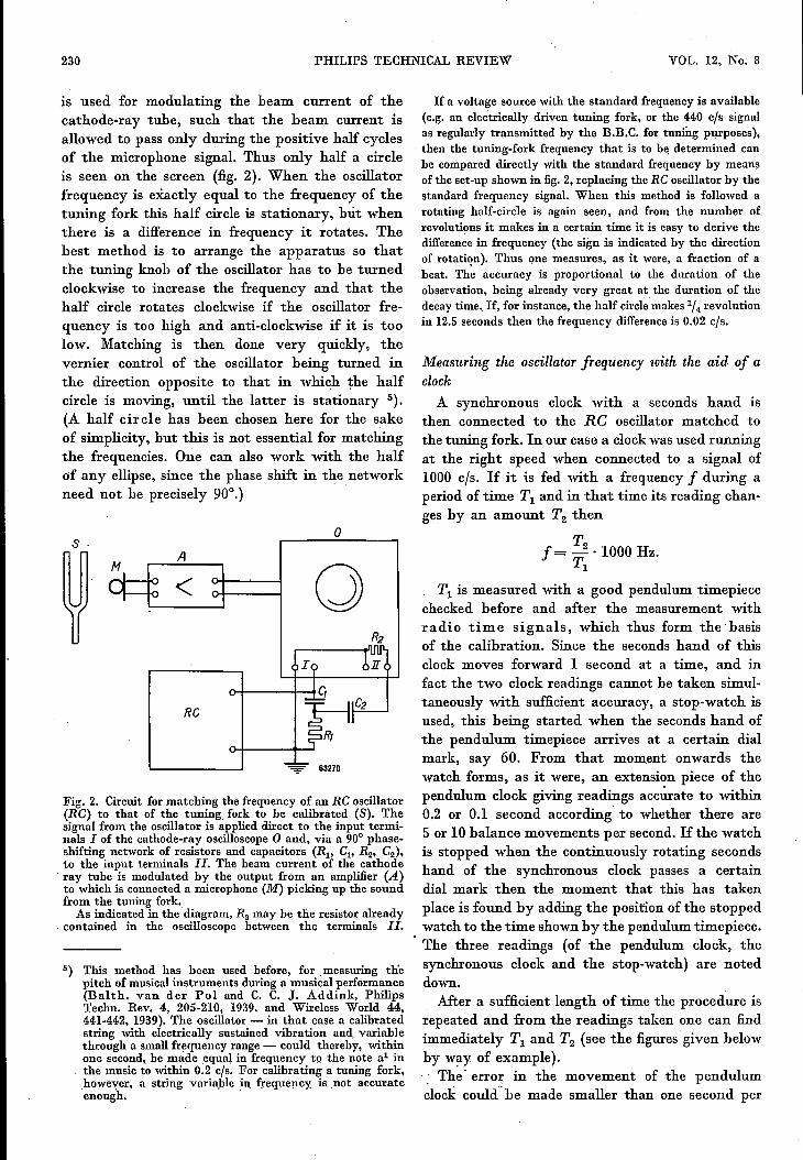
230 PHILIPS TECHNICAL REVIEW VOL. 12, No. 8
is used for modulating the beam current of thecathode-ray tube, such that the beam current isallowed to pass only during the positive half cyclesof the microphone signal. Thus only half a circleis seen on the screen (fig. 2). When the oscillatorfrequency is exactly equal to the frequency of thetuning fork this half circle is stationary, but whenthere is a difference in frequency it rotates. Thebest method is to arrange the apparatus so thatthe tuning knob of the oscillator has to be turnedclockwise to increase the frequency and that thehalf circle rotates clockwise if the oscillator fre-quency is too high and anti-clockwise if it is toolow. Matching is then. done very quickly, thevernier control of the oscillator being turned inthe direction opposite to that in which the halfcircle is moving, until the latter is stationary 5).(A half circle has been chosen here for the sakeof simplicity, but this is not essential for matchingthe frequencies. One can also work with the halfof any ellipse, since the phase shift in the networkneed not be precisely 90°.)
s·A
<
RC
o
o
Fig. 2. Circuit for matching the frequency of an RC oscillator(RC) to that of the tuning fork to be calibrated (S). Thesignal from the oscillator is applied direct to the input termi-nals I of the cathode-ray oscilloscope0 and, via a 90° phase-shifting network of resistors and capacitors (Rl' Cl' R2' C2),to the input terminals 11. The beam current of the cathoderay tube is modulated by the output from an amplifier (A)to which is connected a microphone (M) picking up the soundfrom the tuning fork.As indicated in the diagram, R2 may be the resistor already
contained in the oscilloscope between the terminals 11.
5) This method has been used before, for .measuring thepitch of musical instruments during a musical performance(Balth. van der Pol and C. C. J. Addink, PhilipsTechn. Rev. 4, 205-210, 1939. and Wireless World 44,44-1-442, 1939). The oscillator - in that case a calibratedstring with electrically sustained vibration and. variablethrough a small frequency range - could thereby, withinone second, be made equal in frequency to the note al inthe music to within 0.2 cis. For calibrating a tuning fork,.howe'Çer, a string variable in frequency is .not accuratecnougn.
If a voltage source with the standard frequency is available(e.g. an electrically driven tuning fork, or the 440 cis signalas regularly transmitted by the B.B.C. for tuning purposes),then the tuning-fork frequency that is to be determined canbe compared directly with the standard frequency by meansof the set-up shown in fig. 2, replacing tile RC oscillator by thestandard frequency signal. When this method is followed arotating half-circle is again seen, and from the number ofrevolutions it makes in a certain time it is easy to derive thedifference in frequency (the sign is indicated by the directionof rotation), Thus one measures, as it were, a fraction of abeat. The accuracy is proportional to thc duration of theobservation, being already very great at the duration of thedecay time..If, for instance, the half cirelemakes 114 revolutionin 12.5 seconds then the frequency differenceis 0.02 cis.
Measuring the oscillator frequency with the aid of aclockA synchronous clock with a seconds hand is
then connected to the RC oscillator matched tothe tuning fork. In our case a clock was used runningat the right speed when connected to a signalof1000 cis. If it is fed with a frequency f during aperiod of time Tl and in that time its reading chan-ges by an amount T2 then
T2f= - ·1000 Hz.Tl
Tl is measured with a good pendulum timepiecechecked before and after the measurement withradio time signals, which thus form the basisof the calibration. Since the seconds hand of thisclock moves forward 1 second at a time, and infact the two clock readings cannot be taken simul-taneously with sufficient accuracy, a stop-watch isused, this being started when the seconds hand ofthe pendulum timepiece arrives at a certain dialmark, say 60. From that moment onwards thewatch forms, as it were, an extension piece of thependulum clock giving readings accurate to within0.2 or 0.1 second according' to whether there are5 or 10 balance movements per second. If the watchis stopped when the continuously rotating secondshand of the synchronous clock passes a certaindial mark then the moment that this has takenplace is found by adding the position of the stoppedwatch to the time shown by the pendulum timepiece.The three readings (of the pendulum clock, thesynchronous clock and the stop-watch) are noteddown.After a sufficient length of time the procedure is
repeated and from the readings taken onc can findimmediately Tl and T2 (see the figures' given belowby w~y of example).... The' error in the movement of the pendulumclock could" be made smaller than one second per

FEBRUARY 1951 CALIBRATION OF TUNING FORKS 231
Fig. 3. Complete apparatus for calibrating tuning forks. S the tuning fork to be calibrated,M microphone, Al and A2 amplifiers together forming the amplifier A of fig. 2, 0 oscillo-scope, RC auxiliary oscillator, P pendulum timepiece, F synchronous clock, H stop-watch.
24 hours, i.e. less than 1/105, so that no correctionneed be made for this. Neither is any correctionnecessary for the movement of the stop-watch,since for the purpose of this test it runs for such ashort time that any error can be ignored.The reading errors at the beginning and at the
end of the time Tl being additive, when a stop-watch is used that can be read accurately to within0.2 s the duration of Tl is known accurately towithin 0.4 s. Since, as deduced above, the measure-
ment with a tuning fork of about 440 cis has to beaccurate within about 0.01%, the duration of Tl hasto be at least 0.4/10-4 = 4000 s, thus about one hour.(With a stop-watch recording time to within 0.1 sthe duration of Tl need be only half an hour.)
A picture of the complete calibrating apparatusis given in fig. 3.
Some readings taken during a practical calibration aregiven below.
The watch was started when the pendulum clock showed2 hrs 37' 0" and stopped when the seconds hand of the syn-chronous clock passed a given mark of the dial, viz. whenthis clock showed 3 hrs 55' 35". The stop-watch then showed7.2". Thus at the moment that the synchronous clock showed3 hrs 55'35" (the beginning of T2) the time shown by the
pendulum clock was 2 hrs 37'7.2" (the beginning of Tl)'After about one hour, at 3 hrs 31'0" on the pendulum clock,the stop-watch was started again and then stopped when thesynchronous clock showed 4 hrs 19'20" (end of T2). The stop-watch then showed 7.8" and was thus stopped at the time3hrs 31'7.8" on the pendulum clock (end of Tl)'
Thus we find: Tl = 3 hrs 31'7.8" - 2 hrs 37'7.2" = 3240.6",and T2 = 4 hrs 19'20" - 3 hrs 55'35" = 1425". Thus f =(1425j3240.6) X 1000 cjs = 339.73 cjs.To minimize any inaccuracy due to errors in reading, the
start and the finish of Tl and T2 are repeated twice; of the threereadings thus obtained the identical ones are usually correct.
Correction of the tuning fork
If the tuning fork tested is found to deviate fromthe desired frequency then one will want to correctit. If the frequency is too low this can be doneeasily; the exact frequency can be approached veryclosely by removing a little material from the endof the prongs of the fork. This has to be done insuch a way however, that no difference in thelengths of the prongs is introduced, for the slight-est difference considerably increases the damping.For this reason, bifurcurated rotationally cylin-drical tuning forks were adopted (fig. I). Theprongs can be shortened as required by stoppingthe saw cut temporarily with, for example, a strip

232 PHILIPS TECHNICAL RÈVIEW' . VOL. 12, No. 8
of brass, and then sbaving the end face in a lathe.Once tbe frequency f of the tuning fork has
been measured, then using the formula givingthe frequency as a function of the dimensionsand material constants, an accurate calculationof the requisite modification can be made. Theformula is 6):
where 1(2 is a factor dependent upon the shapeof the tuning fork, v is the velocity of sound in thematerialof the fork, I the length of the prongs andlo a constant, which in tbe present case is smallcompared with I (a few %). The length of theprongs is taken to be the distance from the vibra-tion node to the tip; with the form described abovethe vibration node lies on one level with the centreof the bore at the bottom of the saw cut.
After the prongs of a fork having too low afrequency have been shortened by tbe amountcalculated according to this formula, the remainingfrequency deviation is usually less than the tole-rance allowed (± 0.2 cis).If the tuning fork has a frequency slightly too
h ig'h it is still possible to correct it, by making theprongs a little thinner at the level of the vibrationnode. It can hardly be calculated in advance, how-ever, how much material has to he removed, andfurthermore the appearance of the tuning fork is
6) See, e.g., Handbuch der Physik, part. 8, p. 207 (Springer,Berlin 1927).
thereby spoiled. For this reason the uncorrectedtuning forks are always given a frequency slightlytoo low.
This type of fork is made in a lathe and a milling machine.A rod is turned to produce the required diameters for theprongs and the stem, and symmetry is assured. A hole is nowdrilled at a right angle through the axis of the rod. A slot,in line with the drilled hole, is cut along the axis of the rodon a milling machine. It is obvious that this is a much simpler.process than that of making the usual rectangular cross sectionfork. .So as to have a light and stainless product a hard aluminium
alloy was chosen instead of steel, although it has a some-what greater absolute temperature coefficient.A disadvantage due to the shape and the material chosen
is that the fork has a weaker tone and a shorter vibrationtime than the usual fork when placed on a sounding board.However, this fork gives better results when held close tothe ear, especially at low frequencies, owing to the relativelylarger radiating surface of the prongs.
Summary. A method is described by means of which tuningforks can he calibrated without requiring an acoustic standardfrequency. With the aid of a cathode-ray oscilloscope thefrequency of an RC oscillator is matched to that of the tuningfork to be calibrated. Connected to this oscillator is a syn-chronous clock, the seconds hand of which would make onerevolution per minute if the frequency were 1000 cis. 1£,after an interval Tl' this clock shows a difference in readingT2 then the frequency sought is f = (T2ITI) • 1000 cis. Theduration of the interval Tl is measured with the aid of apendulum timepiece the movement of which is checkedbefore and after the measurement with radio time signals.
1£ the frequency found is lower than that required then thelatter can be very closely approximated by shortening slightlythe prongs of the tuning fork. A special, cylindrically shapedtuning fork is described, with which this correction can be madeeasily on a lathe, thus retaining the required symmetry.