pre-feasibility study of copper smelter plant –ii
TRANSCRIPT

Pre-Feasibility study of Copper Smelter Plant –II
1.0 INTRODUCTION
About the Company Vedanta Ltd., is a group company of Vedanta Resources Plc.London. Vedanta Limited is one of the world’s largest diversified natural resource companies listed on BSE, NSE and NYSE. Vedanta Ltd., produce copper, zinc, lead, silver, aluminium, iron ore, oil & gas and commercial power and have a presence across India, South Africa, Namibia, Ireland, Australia, Liberia and Sri Lanka. Sustainability is at the core of Vedanta’s strategy, with a strong focus on health, safety and environment and on enhancing the lives of local communities. Vedanta Ltd., has a strong track record in managing operations and improving costs and output. Indian zinc and copper operations rank in its top quartile of global cost efficiency. Vedanta Ltd., is the first company in India to set up a Copper Smelter and Refinery in private sector and operate the largest capacity continuous Cast Copper Rod plants. The main products are Copper Anodes, Cathodes and Rods, which meet global quality benchmarks. Project Background The first integrated copper Smelter -I complex at Thoothukudi was commissioned for commercial production during 1997. The company owns copper mines in Australia and remaining requirements of copper concentrate is imported from Chile, South America, Australia and Indonesia. The proposed Copper Smelter –II project is a green field project.
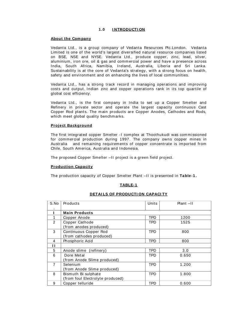
Production Capacity The production capacity of Copper Smelter Plant –II is presented in Table-1.
TABLE-1
DETAILS OF PRODUCTION CAPACITY
S.No
. Products Units Plant –II
I Main Products 1 Copper Anode TPD 1200 2 Copper Cathode
(from anodes produced) TPD 1525
3 Continuous Copper Rod (from cathodes produced)
TPD 800
4 Phosphoric Acid TPD 800 II 5 Anode slime (refinery) TPD 3.0 6 Dore Metal
(from Anode Slime produced) TPD 0.650
7 Selenium (from Anode Slime produced)
TPD 1.200
8 Bismuth Bi sulphate (from foul Electrolyte produced)
TPD 1.800
9 Copper telluride TPD 0.600

(from foul Electrolyte produced) 10 Nickel sludge (from foul Electrolyte
produced) TPD 30
11 Nickel (from foul Electrolyte produced) TPD 1.500
III By-Products 12 Sulphuric Acid TPD 4800** 13 Ferro sand TPD 3000 14 Gypsum TPD 4200 15 Hydrofluro-Silicic Acid TPD 80
** - Sulphuric Acid Plant will be designed for 5900 TPD considering the extreme
case scenario of sulphur content in the Copper Concentrate.
Significance of the Project
Copper application areas covers wide varieties of different disciplines like, Architectural, Electrical, Automotive, Tube, Pipe, Fuel gas, Industrial, Marine and Machine products which gives a great demand. Copper is a strategic metal for development of industry in India. It is considered to be the third most important industrial metal next only to iron and aluminium. Combination of its excellent properties such as high electrical and thermal conductivity, high strength, malleability, easy workability, corrosion resistance and its ability to produce alloys with other metals in an attractive range of colours has made copper a strategic metal for the engineering industry. Specific applications of copper include power cables and wires, jelly filled cables, building wires, air conditioning and refrigeration tubing, Telecom, Power, Construction, Transportation, Handicrafts, Engineering, Consumer Durable, Defence, etc. With Indian economy poised for growth, development in infrastructure and power sector will lead to demand of copper. The per capita consumption of copper in India is only in the range of 0.5 kg, when compared to China’s per capita consumption of approx. 4.6 kg and world average of 2.4kg. (Source: Ministry of Mines, Govt. of India). Prior to setting up of the Copper Smelter at Thoothukudi by the Company (Vedanta Ltd.,), the country was a net importer of Copper. Post setting up of the copper smelter by the Company, the country is able to earn valuable foreign exchange and hence improves the Current Account Deficit. Description of Plant Site Copper Smelter Plant -II is located in the SIPCOT Industrial Complex, Therkku Veerapandia Puram Village, Thoothukudi. The Total area earmarked for is 128.805 Hectare of land allotted by State Industries Promotion Corporation of Tamil Nadu Limited, (SIPCOT), a Government of Tamilnadu undertaking specially for promoting industrial development.
State Industries Promotion Corporation of Tamil Nadu Limited ('SIPCOT') handed over land of 131.3 ha for 1200 TPD Copper smelter Plant – II. SIPCOT and executed three lease deeds, one, dated 16-02-2009 (for 36.16 hectares of land), the second, dated 07-10-2009 (for 93.33 hectares of land) and the third dated 03-06-2010 (for 1.84 hectres) in favour of the Company at SIPCOT Industrial Complex, Thoothukudi and handed over the land as per lease agreements to the Company.
Copper Smelter –II will be located in 128.805 ha. and the Land kept in hand in Zone –A for future purpose is 2.585 ha.
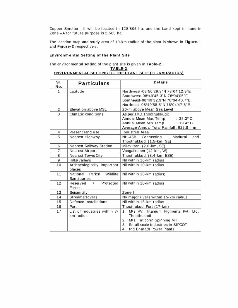
The location map and study area of 10-km radius of the plant is shown in Figure-1 and Figure-2 respectively. Environmental Setting of the Plant Site The environmental setting of the plant site is given in Table-2.
TABLE-2 ENVIRONMENTAL SETTING OF THE PLANT SITE (10-KM RADIUS)
Sr. No.
Particulars Details
1 Latitude Northwest-08o50’29.9”N 78o04’12.9”E Southwest-08o49’45.3”N 78o04’05”E Southeast-08o49’32.9”N 78o04’40.7”E Northeast-08o49’58.8”N 78o04’47.8”E
2 Elevation above MSL 20-m above Mean Sea Level 3 Climatic conditions
As per IMD Thoothukkudi: Annual Mean Max Temp : 38.3o C Annual Mean Min Temp : 19.4o C Average Annual Total Rainfall :625.8 mm
4 Present land use Industrial Area 5 Nearest Highway NH-45B Connecting Madurai and
Thoothukkudi (1.5-km, SE) 6 Nearest Railway Station Milavittan (2.0-km, SE) 7 Nearest Airport Vaagaikulam (12-km, W) 8 Nearest Town/City Thoothukkudi (8.4-km, ESE) 9 Hills/valleys Nil within 10-km radius 10 Archaeologically important
places Nil within 10-km radius
11 National Parks/ Wildlife Sanctuaries
Nil within 10-km radius;
12 Reserved / Protected Forest
Nil within 10-km radius
13 Seismicity Zone-II 14 Streams/Rivers No major rivers within 15-km radius 15 Defence Installations Nil within 15-km radius 16 Port Thoothukudi Port (17-km) 17 List of Industries within 7-
km radius 1. M/s VV. Titanium Pigments Pvt. Ltd,
Thoothukudi 2. M/s. Tuticorin Spinning Mill 3. Small scale industries in SIPCOT 4. Ind Bharath Power Plants

FIGURE-1
LOCATION MAP OF THE PLANT

FIGURE-2 STUDY AREA MAP (10-KM RADIUS)
Infrastructure Facility
The SIPCOT industrial complex is fully developed industrial estate provided with all types of infrastructure facilities such as road, rail and goods yard, water supply drainage etc. The SIPCOT area is well connected by road and rail. Power is readily available through separate sub-stations. Thoothukudi port is located at a distance of 17-km, which provides additional advantage and facilities for import and export of materials required by the industries in the region.

1.1. Smelter Operation
The copper anodes are produced from the imported copper concentrate through pyro-metallurgical (smelting) processes. The sulphur dioxide generated during the smelting of copper is converted into sulphuric acid by Double Conversion Double Absorption (DCDA) process. A part of this sulphuric acid is captively utilized for production of phosphoric acid from the imported rock phosphate using a Hemi-hydrate-Di-hydrate process. The copper anodes are next dispatched to the refinery unit for further electrolytic refining to about 99.99% purity, which is necessary to obtain the required electrical conductivity for electrical applications. The principal raw material for the production of copper metal at Vedanta Ltd., is copper concentrate containing about 25-35% copper, 25-32% sulphur, iron 25-30% and 7-10% moisture. The major steps in copper extraction include: Blending of different grades of concentrates; Smelting of concentrates in ISASMELT furnace to produce an intermediate
copper rich product known as ‘matte’ containing 60-65% copper and eliminate iron as iron silicate (Ferro Sand) by adding silica;
Converting liquid matte to blister copper (98-99% Cu) in Pierce-Smith
converters (PS converters); Fire refining of blister copper to produce anode copper (99.5% Cu) in anode
furnace and casting of the anodes; and Electrolytic refining of anodes to produce copper cathodes (99.99% Cu).
In the process of extraction of copper metal from copper concentrates, sulphuric acid is recovered as a by-product from the sulphur dioxide emanating from the ISASMELT and PS converting furnaces.
1.2 Brief Process Description - Smelter Plant
ISASMELT is an established, novel pyro-metallurgical bath smelting process for the extraction of copper from copper concentrates. The process comprises of smelting the copper concentrate in a vertical, cylindrical, refractory brick lined, flat roofed furnace vessel. A central lance injects air, oxygen and fuel into the molten bath of ferro sand and the matte. The oxygen enriched air and fuel down the lance violently stirs the liquid vigorously. These lances are the proprietary supply of the technology supplier. These lances are a ‘pipe within pipe’ assembly. They are constructed from a composite of stainless and mild steel and incorporate specially designed helical gas swivel that enables the use of low-pressure air and oxygen. Controlled swiveling of the process gases inside the lance cools the outer section sufficiently to solidify a layer of ferro sand around the outer surface of the lance. This provides a protective coating in the highly aggressive bath environment. The lance goes through the top of the furnace into the bath and the SO2 off-gases from the furnace pass up through an uptake shaft to a waste heat recovery boiler (WHRB) and the gases pass through an electrostatic precipitator for the removal of the dust before the gases are conveyed to the sulphuric acid plant.
The products of the ISASMELT process, matte and ferro sand are tapped periodically from the bottom of the furnace through a water-cooled copper tap

hole. The matte and ferro sand then flow into a Rotary Holding Furnace (RHF) where the matte separates from the ferro sand due to density. The ferro sand from the rotary holding furnace / Ferro sand cleaning furnace is granulated in a dedicated ferro sand granulation system and the granulated ferro sand is discarded to a place inside the smelter plot for beneficial applications.
The matte (63±3% Cu) is conveyed through ladles to Pierce Smith (PS) Converters for conversion to blister copper by blowing process air into the bath through tuyeres. The SO2 off gases from the PS converter is passed through an ESP for the removal of residual dust before being led to acid plant for the production of sulphuric acid. The blister copper is further treated in anode furnaces by fire refining and cast into anodes for electro-refining in an ISA REFINERY to a saleable copper cathode of 99.99% Cu purity.
1.2.1 Operational Theory of Smelter
The copper concentrate is selectively oxidized in the bath of the ISASMELT furnace in such a way to liberate part of SO2
and the exothermic heat from reactions inside the furnace raises the temperature of the constituents above their melting point. The instantaneous smelting reaction forms molten mass of Cu2S, FeS, FeO and Fe304. Further reaction takes place in the molten mass where FeO reacts with the silica in the charge to form ferro sand. Two separate liquid phases are formed in the rotary holding furnace. After the removal of ferro sand by granulation, molten matte from the RHF furnace containing about 63±3% copper is poured from the RHF at about 1200oC into ladles and six ladles of 10m3 are transferred through EOT cranes to the Pierce-Smith converter. In converter, air is blown to the liquid matte at 150 kPa pressure through side-blown tuyeres, and quartz added as a flux in three stages results in production of the blister copper. The operation of converter is autogenous and exothermic; the heat of reactions is more than sufficient to maintain the operating temperatures. The products from converter are blister copper (about 98.5% Cu) and ferro sand (approx. 5-7% Cu).
The ferro sand from the converters is cleaned in a ferro sand cleaning furnace for reducing copper in discard ferro sand. The ferro sand is allowed to settle in ferro sand cleaning furnace where again two layers of molten matte and ferro sand are formed. Matte from ferro sand cleaning furnace is treated in converters whereas ferro sand is granulated and discarded.
The off gases from ISASMELT furnace and converters after cleaning and cooling are utilized for the production of sulphuric acid.
Blister copper poured from converter to ladles is transferred to anode furnaces by means of EOT cranes for further fire refining. Controlled air blow first oxidizes remaining sulphur to remove as sulphur dioxide. However in the process, part of copper is also oxidized, which is reduced back by reduction with hydrocarbons available from cracking of LPG. The fire-refined copper containing about 99.7% Cu is cast on rotating anode casting twin wheel as anodes each weighing about 390kg. The anodes are dispatched to tank house for electro-refining.

1.2.2 Brief Process Description - Electrolytic Refinery
The anodes cast in the smelter section are electro refined in electrolytic cell to produce cathodes based on the process technology developed at CRL, Townsville, Australia by Xstrata Technology, Australia. The process commonly known as ISA process uses permanent stainless steel electrodes as cathodes and copper anodes from Smelter as anodes in the electrolytic cells. Electrolysis of copper anodes is carried out by passing Direct Current from the rectifier. Copper ion from anode dissolves in electrolyte and gets deposited on the stainless steel cathode as sheets. The copper deposits are mechanically stripped from both sides of the stainless steel mother blanks. After stripping the S.S. mother blanks are recycled back to the electrolytic cell for subsequent use. The stripped copper deposits form the 99.99% pure Copper production from Cell house. One anode cycle lasts nearly three weeks and three cathode crops are drawn at weekly intervals.
The anodes after receipt from smelter are unloaded on to the feed conveyor of the anode preparation machine. The machine accepts good anodes and rejects bad anodes on weight basis. The anodes are pressed to straighten and lugs are milled in the machine for ensuring better electrical contacts. Prepared anodes are discharged on to separate spacing conveyors with desired spacing for loading into the electrolytic cells by tank house overhead cranes. The anodes (57 Nos.) and stainless steel cathodes (56 Nos.) are placed in each electrolytic cell with a pitch of 100 mm, arranged in 40 sections of 30 cells each filled with electrolyte, with a composition of 38-55 gm/liter Cu and 150 - 190 gm/liter H2SO4. The electrolysis of copper anode is carried out by applying a current density applied is 313 Amp/m2
of cathode surface. The electrolyte in the cells is circulated continuously at 65ºC to facilitate the nodular free uniform deposit of copper on cathode. The electrolyte is pumped from a circulation-collecting tank to an overhead tank through a heat exchanger. From the head tank, the electrolyte flows down under gravity to feed each cell at the rate of 35 liter/minute. The electrolyte enters the cell at bottom and leaves from the top ensuring the flow of the electrolyte throughout the cell. The return from the cells flows to circulation tank, through a mist eliminator. Additive reagents like Gelatine or Glue, Thiourea, HCl, etc are added to circulating electrolyte to improve the quality of the cathode deposit. To arrest the floating slime in the electrolyte a polishing filter continuously filters around 30% of the electrolyte in circulation.
The cathodes are harvested on a seven day cycle, constituting three cathode crops out of each anode cycle of 21 days. At the end of each harvest of 7 days, the cathodes are pulled out of the electrolyte cells. During this pulling time the entire block of cells is by passed from the main electrical circuit by means of electrical shunt and switch system. The 56 nos. of cathodes are lifted from the each cell by lifting bail attached to an overhead crane and transported to the cathode-stripping machine. In stripping machine, the cathodes are washed by high-pressure jet water in washing chamber. After washing the cathodes are flexed to release the copper deposits from the SS cathodes (Mother blanks). The deposited copper mass is stripped off from the blanks as copper cathode sheets and stacked one over other. The copper cathode sheets are stacked to a predetermined bundle size; it is further conveyed to next station for weighing.
The stripped mother blanks are advanced to the discharge conveyor and spaced at the desired pitch. The set of mother blanks, each consisting of 56 blanks, are lifted by lifting bail of overhead crane to place into electrolyte cells for start of new cathode cycle.

At the end of anode cycle, the anode scrap weighing around 50 kg each is removed from the cells by over head crane and placed in the feed conveyor of Anode Scrap Washing Machine, for washing of anode slimes from the anode scrap. The washed scrap anodes are recycled back to smelter.
The insoluble part of anodes, which consists of copper and precious metals settle down at the bottom of cells as anode slime during electro refining. After each anode cycle of 20 days, the electrolyte cells are washed with water and the anode slimes are collected in the slime storage tank.
In slime treatment plant, anode slime containing approximately 35% Cu, is treated with sulphuric acid at elevated temperature to reduce copper content. After leaching operation, the copper free slimes are filtered and treated further for separation of nickel, selenium and tellurium. Finally, precious metals, like silver and gold are recovered from the slime as dore metal. From the filtrate, tellurium is precipitated by cementation and tellurium free solution returned to electrolyte purification circuit.
During refining process, copper dissolves in electrolyte and impurities like nickel, arsenic, antimony, bismuth, and selenium etc., also go into the solution. For the production of the good quality cathode the impurities level in electrolyte should be as low as possible and the copper content in the electrolyte required to be maintained at the desired value. This is achieved by withdrawing a small portion of electrolyte from the electrolyte circulation system as a continuous bleed. The electrolyte bleed stream is treated in purification plant where in liberator cells electro winning of copper from electrolyte reduce the copper content. A portion of the treated electrolyte is recycled back to main circulation system and some portion is sent to WWTP for final treatment. During electro winning in liberator cells, arsenic, antimony, bismuth are precipitated and collected as a copper arsenic sludge for disposal.
1.2.3 Brief Process Description - Sulphuric Acid Plant
The sulphur dioxide gases generated during the copper concentrate smelting in ISA and matte converting operation in PS converter of copper smelter plant are treated in sulphuric acid plant for the production of sulphuric acid as a byproduct. The process of production of sulphuric acid consists of three principal steps:
Cleaning of the sulphur dioxide gas from the ISASMELT furnace and PS
converters;
Catalytic conversion of the sulphur dioxide (SO2) gas to sulphur trioxide (SO3) gas according to the chemical reaction:
SO2
+ ½ O2 (SO3)
Absorption of the sulphur trioxide (SO
3) gas by reacting with diluted H2SO4 to
form concentrated sulphuric acid (H2SO4).
The conversion of SO2 to SO3
is an exothermic, reversible and adiabatic reaction and with increase in temperature the equilibrium constants become more unfavorable with respect to SO3
formations. The other factors, which favour equilibrium conversions, are increase in oxygen concentration in the gases and or high pressures but the relative gains are rather small. In contrast to the unfavorable effect of high temperature on equilibrium it is found that the rate of reaction increases rapidly with rising temperature. Consequently, optimum

performance requires a balance between the opposing effects of reaction rate and equilibrium. Thus, the gases entering the V2O5
catalyst normally are maintained between 400 - 450ºC. Therefore, in order to achieve over-all high conversion efficiencies between 99.6% - 99.7%, it is imperative that the converter gases need to be cooled between stages to the above temperature range and also removing the partially converted sulphur trioxide formed normally after 2nd/3rd beds, before returning them to subsequent stages. This process is commonly known as Double Conversion and Double Absorption (DCDA).
1.2.3.1 Purification of SO2 Gas
The SO2 gas from the smelter and PS converters contains metallic dust, fume,
acid mist, water vapour and various other impurities like halides etc., which are not only detrimental to the catalyst used for conversion in the sulphuric acid production but also contaminate the product. The gases are therefore cooled, cleaned in the gas cleaning plant comprising of gas cooling tower, Dynawave
Scrubbing System and wet electrostatic precipitators. A portion of the weak acid from circulation system of the scrubbers is continuously bled, which is predominately consists of the halides like, fluoride, chlorides etc., to the Wastewater treatment plant. The wet gas precipitator electrically removes the acid mists formed during the downstream operations and optically fully saturated SO2
bearing gases are conveyed to the sulphuric acid plant. 1.2.3.2 Drying, Conversion and Absorption of SO2 to SO3
The optically cleaned SO2
rich gases along with dilution air to the extent required for maintaining the requisite O2
/SO2 ratio are dried in a drying tower with 96%
concentrated sulphuric acid in counter current circulation. The dried gases after heating to 400-450 ºC passed through converter with cesium promoted vanadium pentoxide catalyst. The converted SO3
gases are absorbed in two absorption towers where 98% concentrated sulphuric acid is circulated to produce 98.5% strength Sulphuric acid product.
CESIUM CATALYST AND XLP RING DESIGN
MECS provides guarantee on SO2 conversion through its highly active, low pressure drop catalyst. MECS XLP catalyst reduces pressure drop compared to ring type catalyst used in the same converter. Because of this, in a new plant the pre ssure drop can be reduced significantly. This ring type design is also used for Cesium catalyst, which was first patented by MECS in the 1960s. Cesium lowers the temperature at which initial conversion takes place, allowing MECS to guarantee ultra-high levels of SO2 conversion (>99.9%) without the use of a tailgas scrubber.
1.2.4 Brief Process Description – Phosphoric Acid Plant The production of phosphoric acid is based on well known Hemihydrate Dihydrate process. The main raw materials for the phosphoric acid production are rock phosphate and sulphuric acid. The rock phosphate is reacted with sulphuric acid in a series of reactors to produce phosphoric acid. The solid waste (phosphogypsum) generated in the process is separated and transferred to the low / high density polyethylene lined gypsum pond through pipe conveyers. The off gas from the reaction containing hydrogen fluoride is scrubbed and converted to hydro fluro silicic acid, which is sold as a byproduct.

1.3 Plant Facilities The major technological units envisaged for the copper smelter plant are as given below:
Raw Material Handling System; Isasmelt Smelting; Converting; Ferro sand Cleaning and Disposal; Anode Refining and Casting; Electrolytic Refining; Continuous Copper Rod; Sulphuric Acid Plant; Phosphoric Acid Plant; and Oxygen Plant.
1.3.1 Raw Material Handling System
Copper concentrate and rock phosphate will be imported from various sources at Thoothukudi port through shipment. These materials will be transferred into warehouse by tippers / wagons. The Copper Concentrate and the rock phosphate will be stored in separate warehouses. Similarly, other raw materials (fluxes) required for smelting viz. silica, limestone and quartz, will be procured from indigenous sources and stored in the raw material storage area, outside the warehouse.
1.3.2 ISA Smelting The process for the smelting of copper from the copper concentrate by ISASMELT process, which is a proprietary technology of M/s Xstrata Technologies, Australia. The process flow diagram of ISA smelter and Rotary furnace is shown in Figure-1.1.

FIGURE-1.1 PICTORIAL DIAGRAM OF ISA SMELTER AND ROTARY FURNACE

The ISA smelting comprises of the following main facilities:
Furnace Building; Furnace Raw Material Feed System; The Smelting Furnace; The Lance Handling And Services System; Molten Matte/ Ferro sand Handling System; Off Gas Handling System; Waste Heat Recovery Boiler System; Super Heater System in Sulphuric acid plant WHRB; Turbine Generator System; Air Cooled Condensers; Cooling Water System; and Hygiene Ventilation System.
1.3.2.1 Molten Matte/ Ferro sand Handling System
The furnace matte/ ferro sand is periodically tapped from the tap hole, which is provided with water cooled copper block. The tap hole is opened by a tap-gunning machine. The ferro sand/ matte together flow by gravity to the Rotary Holding Furnace (RHF) for ferro sand and matte settling and separation. The operation is being carried out in a horizontal cylindrical furnace MS shell lined with refractory. It is fired by Oxy-fuel burner to maintain the operating temperature of around 1200ºC. The off-gases are passed through a venturi before being led to the common hygiene ventilation system for scrubbing. Ferro sand settled in the Rotary Holding Furnace (RHF) is being granulated separately in a dedicated launder system and is collected in the collection pond. Ferro sand granulation water overflows into a water pond, cooled in a spray pond and recycled to the nozzles of the granulation launders.
1.3.2.2 Off-Gas Handling System and WHRB System
The ISASMELT furnace is maintained under negative pressure at all times to ensure proper capturing of hot process SO2
bearing off –gases and these gases are utilized for the recovery of the sulphur content as saleable byproduct of sulphuric acid.
The hot SO2
gases from the ISASMELT furnace, before being led to the sulphuric acid plant passes through a waste heat recovery boiler (WHRB) to recover the heat to produce approximately 75 t/h of fully saturated steam at 77 bar a. The WHRB has a radiant section and a set of convection bank pendant tubes. The steam produced in the WHRB of ISASMELT is utilized to produce 7 MW of power in a condensing steam turbine set. The excess steam produced is utilized for process requirements.
A major content of the dust carried over in the off-gases is recovered underneath the WHRB through an air cooled drag chain conveyor and fed to a crusher together with the ESP dust for grinding to a size fraction suitable for pneumatic conveying to the recycle bin located in the day bin Building.
Off gases from the waste heat boiler gets cooled to a temperature of 350ºC and are further conveyed to a hot ESP having dust collection efficiency to achieve a dust content of approximately 100mg/Nm3. To maintain the manometric balance for the downstream equipment described above and maintain a negative suction pressure at the ISASMELT furnace inlet; an intermediate fan (ID fan) having a

capacity of 120,000 Nm3/hr is provided after the hot ESP. The ID fan further delivers the off-gas to the gas cleaning section of the sulphuric acid plant for cooling and removal of the harmful impurities like fluorine, chlorine, arsenic etc before being sent to sulphuric acid plant for manufacture of sulphuric acid.
1.3.2.3 Hygiene Ventilation System
A provision has also been kept to collect secondary gases arising from ISA and RHF operations and is being treated in Hygiene Ventilation System having capacity of 362000 NM3/hr.
The Secondary emissions from ISA and RHF (such as the feed port, tapping port) are captured through hood arrangements and are scrubbed in the ISA/RHF Hygiene Ventilation Systems (HVS). The HVS consists of venturi scrubbers and demister arrangements. Milk of Lime is used as a reagent for scrubbing the secondary gases. The scrubbed gases, free of SO2 except for some traces are vented through a stack.
1.3.3 Converting using PS Converter
1.3.3.1 Raw Material Feeding System
Crushed revert and quartz (SiO2- 90% to the size of 20 - 25 mm) are fed to the converters during the operation. Two sets of bins consisting of two bins each (one for quartz and one for revert) exists for converters. These bins are filled by a common conveyor system. Materials from these bins are reclaimed by vibro-feeders located below the bunkers and the reclaimed material is fed to the Converters.
PS Converter charging system is provided with dust extraction system (ESP) to prevent escape of dust to the atmosphere.
1.3.3.2 P.S. Converter
Molten matte tapped from the rotary holding furnace (RHF) in 10 m3
ladles is transferred to Pierce-Smith converter with the help of an E.O.T. crane. 4 Nos. of Cranes having capacity of (80 tonnes). Four converters (3 hot + 1stand by) exist with two converters in operation at a time.
During converting operation, air under pressure is passed through the specially designed tuyeres into the molten bath. The air oxidizes the matte to form ferro sand and blister copper. Crushed quartz (20-25 mm size) is added as flux in the converter. Quartz is being stored in a hopper located centrally between two converters. Weighed quantity of quartz is delivered to converter through weigh feeders. The converting process is a batch operation taking about 5.0 hours for producing 125 tonnes of blister copper in each cycle. The blister copper is transferred for further processing in the anode furnaces through dedicated blister copper ladles having a capacity of 7-m3
each. Ferro sand with 7 to 10% copper is tapped intermittently into ladles having a capacity of 10-m3 and recycled to rotary Ferro Sand cleaning furnace for recovery of contained copper content into matte and fixation of iron as ferro sand.

Converter off-gases at 1200oC are collected in double hood system. The converter hoods are in two sections; water cooled primary hood through which process SO2 off gases are collected having a capacity of 2,40,000 Nm3/hr gas handling capacity and secondary hood through which secondary gases are collected.
The gases then passes through an electrostatic precipitator (ESP) with a capacity of handling 240,000 Nm3/hr gas flow, to minimize dust carry-over to the sulphuric acid plant. Dust collected from off gases in ESP is recycled to ISASMELT furnace through a pneumatic conveying to the recycle bin located in the day bin Building. Converter SO2
off-gases are finally sucked by I.D fans and delivered to Mixing chamber where they mix with ISASMELT furnace gases and utilized for sulphuric acid production.
The secondary off-gases from the secondary hoods are conveyed to secondary scrubber having capacity of 470,000 Nm3/hr.
1.3.4 Ferro sand Cleaning and Disposal System 1.3.4.1 Ferro sand cleaning Furnace Charging System
The coke and quartz are the main raw material required during process operation. A small quantity of the pig iron is charged using the shop EOT crane into a charging bin.
1.3.4.2 Ferro sand cleaning Furnace
Ferro sand from PS converter furnaces are transferred to the rotary ferro sand cleaning furnace by ladles with the help of EOT crane. The ferro sand is allowed to settle in the furnace (settling time around 1.25 hrs) where copper in ferro sand settles down and forms a layer of matte. Ferro sand from Ferro sand cleaning furnace is water granulated in a dedicated ferro sand granulation system having a capacity of 400 tpd. Matte (65% Copper) from Ferro sand cleaning furnace are tapped and charged back to the PS converters.
The Ferro sand cleaning furnace consists of steel construction with refractory lining mounted on roller cradles. Oxy-fuel burners are envisaged for heating and maintaining the ferro sand & matte under molten condition. The off-gases generated during Ferro sand cleaning furnace operations are cooled to 350ºC before being led to the common hygiene ventilation system for scrubbing before discharge to the atmosphere.
1.4.4.3 Ferro sand Disposal System
Ferro sand generated in the Ferro sand cleaning furnace is granulated separately in a dedicated launder system and is collected in the collection pond. Ferro sand granulation water overflows into a water pond, cooled in a spray pond and recycled to the nozzles of the granulation launders.
The granulated ferro sand settling pond is provided with a grab crane of 30 tonnes capacity which collects the ferro sand from the pond and discharges the same in a steel bunker. The ferro sand from the steel bunkers is unloaded into the outsourced tippler truck dumper and transported to the designated ferro sand yard within the plant boundary for storage and further sale/ disposal.

1.3.5 Anode Refining and Casting Three number of anode furnaces are used for refining of blister copper to anode copper. Anode furnaces are provided with LPG & Oil burners. Blister copper is received in anode furnaces through ladles (7m3) with the help of EOT crane. Blister copper is first slowly oxidized to remove dissolved sulphur below 50 PPM by blowing air in it through tuyeres. The metal is subsequently reduced by use of LPG to control Oxygen around 1,500 PPM.
Fire-refined copper is cast into anodes (approx. 390 kg each) on rotating twin / single wheel casting machine having a capacity of 110 t/h by means of automatic anode weighing and casting device. Anodes from cast wheel is lifted by means of an automatic take-off device, cooled and stacked on a conveyor for onward conveying to the anodes preparation yard. Hot off-gases from the anode furnaces are drawn by exhaust fan, scrubbed through hygiene ventilation scrubbing (HVS) before discharge to the atmosphere.
1.3.6 Electrolytic Refinery
Electrolytic refinery has two independent units namely;
Tank house; and Purification plant.
The process flow diagram of electrolytic refinery is shown in Figure-1.2(A). The technological facilities in Tank House comprise the following:
Anode preparation facility; Production cells; Electrolytic circulation system; Filtration of electrolyte; Additive dosing facility; Electrolyte storage; Fume extraction; Cathode stripping facility; Anode scrap washing facility; Extraction of slime; Thickener; and Thickener-overflow
The technological facilities in the purification plant comprises of following:
Control cells; Liberator cells; Slime treatment facility; and Fume extraction.
Besides, other major facilities like overhead cranes, rectifiers, bus-bar system, instrumentation and general services exists to meet the requirement of tank house and purification plant. The copper anodes containing about 99.5% to 99.7% copper is electrolytically refined to about 99.99% purity which is necessary to obtain the required electrical conductivity for electrical applications.

The impure anodes contains around 99.5% to 99.7% copper, 0.15% oxygen and traces of other impurities such as precious metals. Anodes and stainless steel cathode plates are suspended alternatively (56 anodes and 55 cathodes) in the electrolysis cell. The electrolytic cells are connected in series to form one bank. A bank can be electrically isolated from others for the purpose of changing anodes and stripping by using short circuit switches. The current passes from cell to cell via intermediate busbars. Direct current required for electrolysis is provided by rectifier. From rectifier current flows through bus bars to banks and provides power for electrolysis.
The electrolytic cells are filled with electrolyte (copper sulphate, sulphuric acid, water and anode impurities). The electrolyte, which flows through cell, is preheated and circulated. The temperature of electrolyte is maintained at 630 C to 650 C and flow is maintained at 25-35 liters per minute per cell. During circulation of electrolyte, other reagents (Glue, Thiourea and hydrochloric acid) are added to achieve smooth fine-grained deposit. Electrolysis is conducted for about five to seven days (this time can be varied according to the current density).

FIGURE-1.2 (A) FLOW DIAGRAM OF ELECTROLYTIC REFINERY PROCESS

Copper is electrochemically dissolved from the anodes and gets deposited on the cathode, at a rate depending upon the strength of the current. The copper deposited cathode plates are removed from the electrolytic cells and are passed through cathode stripping machine, where cathodes are washed and copper is stripped from cathodes plates. The copper is bundled, weighed and strapped ready for use in Continuous Copper Rod Plant (CCR) or dispatched to customers. The mother banks return to the process for further deposition.
The undissolved part of anode, called anode scrap is washed free of electrolyte in Anode Scrap Washing Machine (ASWM) and is recycled back to smelter for remelting as anodes. The insoluble impurities (anode slimes) which settle at the bottom of the cell are collected and subjected to leaching process, where copper is removed from the slime. The leached slime is then filtered, dried and processed further. During Electro-refining, some anode impurities (noble metals and heavy metals) gets dissolved in electrolyte. The build-up of concentration of these impurities in electrolyte solution affects the electrolysis process and results in poor quality of cathode. The concentration of such impurities in the electrolyte is controlled by bleeding off some quantity of electrolyte and making-up with fresh electrolyte solution.
1.3.7 CCR Plant
The CCR plant (Continuous Rod Plant) converts Copper Cathodes into rods by melting and rolling. Copper cathodes contain around 99.99 plus % coppers and is one of the purest forms of commercially available copper. Their copper cathodes are to be processed and made into rods of varying sizes to make them amenable for wire drawing. A brief description of the process is as under:
1.3.7.1 Technology Our technology supplier for copper rod plant is "Continuous Properzi" Italy.
1.3.7.2 Main Raw Material feed The raw material for the process is Copper Cathode of LME (London Metal Exchange) Grade A Quality. These cathodes along with pure in-process scrap from rod plant are used for melting. Cathodes are made into bundles and charged into a Shaft furnace with the help of a Skip hoist.
1.3.7.3 Shaft/Melting Furnace The shaft furnace has LPG / Propane fired nozzle mix burners at the bottom to melt cathode at a temperature of 11000c and this melting temperature is controlled by a computer controlled system. The flame from the burner hits the cathodes and melts the same. Since there are column of Cathodes above the burners, the hot gases pass through the cathodes and transfers sensible heat to the descending charge thus increasing thermal efficiency. The fuel used is free from sulphur as Propane or LPG is used. Consequently there is no pollution of any nature because of Shaft furnace. One specialty of the furnace is that there is no molten metal in the furnace and the metal as it melts freely flows out and the temperature is kept very low to prevent hydrogen pick up. The molten metal flows through covered Launders at a temperature of 11000c to a Holding furnace.

1.3.7.4 Holding Furnace and launder system The holding furnace acts as buffer between melting and "continuous properzi" copper wire rod-making machine. The holding furnace is heated at a temperature of 11000c using Propane / LPG. The same fuel heats the launders. The temperature is kept as low as possible to prevent over oxidation and pick up of Hydrogen.
1.3.7.5 Copper Wire Rod Making Machine - "Continuous Properzi" Copper Bar Preparation Unit
The molten metal from the Holding furnace is transferred to the Tundish through the premix burner fired Launders, whose level is automatically controlled. The Tundish then feeds the metal into a rotating wheel (trapezoidal groove) from one side. Here the metal gets solidified as the wheel cooled with water jet sprays. Solidified hot cast bar comes out of the wheel and passes through automatic shearing machine, cast bar straightener & shaving machine. Here the upper edges are shaved to remove the surface copper oxide scales.
Rolling Mill The copper bar then enters the Rolling mill at about 8500 c. Here it passes through Roughing mill, Intermediate mill and Finishing mill. The cross section is reduced in 11 stages with intermediate sections of triangles & circles to reach the required diameter of rods. Pickling and Quenching
The rod exiting from the rolling mill is passed through Pickling unit (2% IPA solution in water and emulsion mixture) in order to reduce the Surface oxide of the rod. After the pickling the rod is quenched in water to reduce the temperature from 5000 C to 600 C. Drying and Waxing The quenched rod is then dried with compressed air in the Drier unit to remove the water droplets from the rod surface. In the waxing unit, a water-soluble wax is sprayed on the rod to protect the rod surface from tarnishing. Coiling and Packing Wax-coated rod passes through loop forming pipe to form orbital coils of 1.6-m diameter. These coils are produced in 2.2 & 3m weights as per the customer requirement. The rods are then compacted, strapped and stretch wrapped with HDPE Woven cut sheet for dispatch.
1.3.7.6 Wastewater
The only Wastewater generated in the process is the emulsion containing 5 % soluble oil. Discarding of emulsion is after 6 months depending upon roll life of the mill. The soluble oil is sold as secondary oil. The gases from the Shaft Furnace do not contain any sulphur since the fuel (LPG) used is free of sulphur. The NOx content is negligible since combustion is at a very low temperature. There is no SPM as no soot formation takes place and the metal being melted is only a pure sold copper cathode.

The process flow diagram of CCR plant is shown in Figure-1.2(B).
FIGURE-1.2 (B) FLOW DIAGRAM OF CONTINUOUS COPPER ROD PLANT PROCESS
1.3.8 Sulphuric Acid Plant
The sulphuric acid plant has following facilities.
Purification of off-gases in Gas Cleaning Plant; Conversion of SO2 to SO3 in contact section by DCDA process; Production of sulphuric acid in absorption section; Waste heat recovery section; Acid circulation system; Product storage & tanker loading facilities; and Tail gas scrubbing facilities.
The process flow diagram of gas cleaning plant and sulphuric acid plant are shown in Figure-1.3 and Figure-1.4 respectively.
1.3.8.1 Purification of off- gases in Gas Cleaning Plant
The partially cooled and clean gas from the primary gas handling system containing 11% to 12% SO2 is processed in SAP to produce sulphuric acid. The gas from the primary gas handling system is cleaned and condensed in a primary quencher vessel and a retention vessel. These units provide quenching of the hot gas to the saturation temperature and provide retention time for particle condensation and coalescence. In addition to the removal of coarser dust particles, these units, also absorb hydrogen chloride and hydrogen fluoride vapors present in the gas, if any.

The saturated partially cleaned gas, then enter the Venturi Scrubbers where sub-micron particles are captured and removed from the gas. The dust free gases are further cooled in cooling towers and cleaned in wet ESPs for removal of traces of fine particulates if any. The clean gas is next processed in SAP for production of sulphuric acid.
1.3.8.2 Conversion of SO2 to SO3 in Contact Section and Production of H2SO4 in Absorption Section The gas from the Gas Cleaning section, saturated with water at 350o C, is drawn into the Drying Tower under suction from the main blower. Dilution air if required is added at this point to regulate the concentration of SO2 in the gas entering the Converter. The gas is dried by counter-current contact with a stream of 93% acid in the drying tower. Acid mist carryover in the gas stream from the drying tower is reduced by means of a mist eliminator located at the top of the tower. The dry gas from the drying tower is compressed in the main blower. The compressed gas is further heated to a temperature of 4100C in the heat exchangers before it contacts the catalyst (vanadium pentoxide) in the converter. The converter has 4 beds of catalyst. The catalyst beds not only facilitate the conversion of SO2 to SO3, but also controls the increase in gas temperature due to exothermic conversion of SO2 to SO3. The gas from the second converter bed where approximately 94% of the SO2 gets converted to SO3, is absorbed in 98.5% Sulphuric acid in the Intermediate Absorption Tower. Acid mist carryover is reduced by passing the gas through candle type mist eliminators. The gas from the intermediate absorption tower is again processed in 3rd and 4th converter bed where overall conversion of remaining SO2 to SO3 takes place. The gas from the 4th converter bed is again absorbed in 98.5% sulphuric acid in the Final Absorption Tower to produce sulphuric acid of desired strength. The produced acid is stored in storage tanks. Acid mist carryover is reduced through the use of Brownian Diffusion candle type mist eliminators. The gas leaving the Final Absorption Tower is discharged to atmosphere via Stack.
1.3.8.3 Waste Heat Recovery Section
In waste heat recovery system, the DM water is heated in economizer and low-pressure boiler by recovering heat from heat generated during conversion of SO2 to SO3
in converters to produce super-heated steam in SAP.
1.3.8.4 Product Storage The 98.5% sulphuric acid produced is pumped from the product tank. The product acid from the storage tank is loaded in acid tankers for dispatch.

FIGURE-1.3
PICTORIAL DIAGRAM OF GAS CLEANING PLANT
FIGURE-1.4 PROCESS FLOW DIAGRAM OF SULPHURIC ACID PLANT
Drying Tower (DT)
Gas from GCP
Blower
2
3
4
1
Intermediate Absorption
Tower (IAT)
Final Absorption
Tower (FAT)
Converter Bed
WHRB
ATPT Acid Cool
Air Cooler
DM Water
98.5 % H2SO4
Gas Stream Acid Stream
Stack
Product Acid
Waste Heat Recovery Boiler

1.3.9 Phosphoric Acid Plant
In order to balance the generation and the demand of sulphuric acid, a part of sulphuric acid is captively utilized for production of phosphoric acid. The main raw materials for the phosphoric acid production are rock phosphate and sulphuric acid. The rock phosphate is reacted with sulphuric acid in a series of reactors to produce phosphoric acid. The concentration units are equipped with a fluorine recovery plant which produces 80 MTPD of hydrofluosilicic acid as 100% H2SiF6. The plant is equipped with an efficient scrubbing system to meet stringent environmental standards. The following steps are involved in the manufacturing process:
Rock Handling; Reaction; Hemi-hydrate filtration; Transformation; Di-hydrate filtration; Concentration; and Acid storage.
1.3.9.1 Rock Handling Rock phosphate is unloaded at Tuticorin port and brought to site by road or by rail and the rock is unloaded into the silo by means of unloading conveyors. Shovel loaders are used to feed the material to the reclaim hopper, from where the rock is conveyed to the main plant. Rock dust, which emanates from the system is collected, scrubbed with water and sent back to the first reactor.
1.3.9.2 Reaction
There are three agitated reactors in series operation. The reactors are of mild steel with 10 mm thick butyl rubber lining followed by carbon brick lining in three layers. The rock phosphate and recirculated acid slurry from the flash cooler are fed to reactor 1A. 40% of the calcium fed to Reactor 1A is precipitated in Reactors 1 A and 1B. Slurry from Reactor 1A overflows to Reactor 1B and finally enters Reactor 2. In Reactor 2, 98.5% H2SO4 and 36% P2O5 acid are added with the slurry and the remaining calcium in solution is precipitated. The system temperature is maintained at 98-1000 by means of a flash cooling system through which the slurry is pumped from the Reactor 2 to the Reactor 1B. The off gases evolved during reaction and during flash cooling are being scrubbed in reactor off gas unit and in Flash cooler off gas unit respectively. Scrubbing is done with water and hydrofluosilicic acid is produced at a concentration of 18% which is filtered in a silica filter to remove the silica content and the filtered acid is sent for storage.
1.3.9.3 Hemi Hydrate Filtration
This comprises of a horizontal belt filter and the slurry from the flash cooler is fed to the filter and washed counter currently. The acid collected from the first filtrate is product acid of 43% P2O5. Second filtrate is return acid of 36% P2O5 which is pumped back to the third reactor. Before the cake is discharged to the first transformation tank, final washing is done by 9% P2O5 acid from the dihydrate filter. A vacuum up to 0.25 bar is maintained by operating two centrifugal vacuum pumps.

1.3.9.4 Transformation
There are two transformation tanks, made up of mild steel, rubber lined and carbon brick lined, operating in series. An agitator is mounted for better mixing and keeping the slurry in suspension. Hemihydrate cake HH cloth wash liquor and Sulphuric acid are added to tank No. 1 and it overflows to tank No. 2. The residence time is sufficient to achieve conversion of Hemihydrate to dihydrate under controlled conditions and the slurry is then fed to the dihydrate filter.
1.3.9.5 Di-hydrate Filtration
This comprises of a horizontal belt filter and the slurry from the transformation tank is pumped to the filter and it is washed counter currently. The cake undergoes two washings before it is discharged to the gypsum slurry tank. The first filtrate of 9% P2O5 is used as final wash for the hemi-hydrate cake. The second filtrate is used for washing the hemi-hydrate filter cloth.
The gypsum generated is transported to gypsum pond through pipe conveyors to avoid spillage.
1.3.9.6 Concentration
The product acid of 43% P2O5 from the hemihydrate filter is further concentrated to obtain 54% P2O5 in the concentration section. Acid from the hemi-hydrate filter is pumped to the clarifier for removing the solids present before it is pumped to the concentrator. The clarifier is a mild steel rubber lined vessel and acid brick lined at the conical bottom portion. There are two clarifiers, one at the inlet of the concentrator. A centrally mounted rake mechanism is used for removing the sludge from the acid. The clear acid from the clarifier top is pumped to the concentrator and the sludge from the clarifier bottom is pumped back to the third reactor for recovering the entrapped P2O5. There are two concentrators operating in parallel with the fluorine recovery unit.. The concentrator is a mild steel rubber lined cylindrical vessel with a conical bottom. A graphite heat exchanger is used to raise the acid temperature to 850C by means of a low pressure steam (1.5 Kg/cm2). The steam is generated from “Smoke Tube” type Boilers. Acid circulation between the concentrator and the graphite heat exchanger is done by an axial flow pump of high volume and low head. The concentrated acid overflows from the concentrator (flash chamber) to a concentrated acid seal tank and is pumped to the concentrated acid clarifier through three acid coolers. The clarified acid is then pumped to the acid storage tanks. The non-condensable are removed by a vacuum jet system consisting of 2 steam jet ejectors operating on 10 Kg/cm2 steam and an inter condenser operating on cooling water. The ejectors maintain a vacuum of 53 mm Hg (abs.) The gases evolved during concentration are scrubbed in fluorine scrubbing system and the hydrofluosilicic acid (18%) is sent for storage.
1.3.10 Cryogenic Oxygen Plant
Oxygen is required for ISASMELT furnaces continuously and PS converters occasionally, for FSCF & RHF Oxy-Fuel burners intermittently. These oxygen plants consist of main air compressors running simultaneously. The plant produces oxygen (95% purity) and nitrogen (99.9% purity). Argon production is not considered, since argon is not required. Liquid storage for LOX is provided.
1.4 Plant Layout
Copper Smelter Plant -II will be located in the SIPCOT Industrial Complex, Therkku Veerapandia Puram Village, Thoothukudi. The Total area earmarked is 128.805 Hectare of land allotted by State Industries Promotion Corporation of Tamil Nadu Limited, (SIPCOT), Government of Tamilnadu.
State Industries Promotion Corporation of Tamil Nadu Limited ('SIPCOT') handed over land of 131.3 ha for 1200 TPD copper smelter Plant – II. SIPCOT and executed three lease deeds, one, dated 16-02-2009 (for 36.16 hectares of land), the second, dated 07-10-2009 (for 93.33 hectares of land) and the third dated 03-06-2010 (for 1.84 hecatres) in favour of the Company at SIPCOT Industrial Complex, Thoothukudi and handed over the land as per lease agreements to the Company. At present, we have 233.7 ha of land in total. Copper Smelter- I is located in 102.31 Ha. area, Copper Smelter –II will be located in 128.805 ha. and the Land kept in hand in Zone –A for future purpose is 2.585 ha. Green Belt: We have developed Green Belt around the Copper Smelter Plant-II boundary as per the TNPCB direction. We have till date developed 43 Ha of greenbelt in the total area earmarked for the existing and the proposed project site. After the Copper Smelter Plant–II project execution, our total green belt area will become 72.35 hectare as per the environmental clearance issued on 01.01.2009 in and around the existing Copper Smelter Plant-I, Copper Smelter Plant-II and Tamira-I (Employees Quarters) and railway siding area

FIGURE-1.5 OVERALL PLANT LAY OUT

FIGURE-1.6 PROCESS FLOW DIAGRAM OF COPPER SMELTER PLANT –II
Copper Anode
Matte
Matte + Ferro Sand
H2Si F6 H3 Po4
Rock Phosphate
H2SO4 Sale
H2SO4
Oxygen SMELTING FURNACE (1 No)
Cu Concentrate
PIERCE SMITH CONVERTERS
(4 Nos.)
ANODE FURNACES
(3 nos)
OXYGEN PLANT (1 No)
SAP (1 No.)
RHF (2 Nos.) FERRO SAND CLEANING
FURNACES (2 Nos.)
Ferro Sand
REFINERY (1 No)
WHRB Turbine
Copper Cathodes
CCR
PAP (1 No)
Gypsum (Sale)
Energy
Blister Copper
PRECIOUS METAL PLANT
(1 No.)
Ferro Sand Granulation
Ferro Sand

1.5 Proposed Copper Smelter Plant –II -
Copper Smelter Plant –II is designed for the capacity of 1200 TPD of copper anodes production. The major design parameter of proposed copper smelter is presented in Table-1.1. The process flow diagram of the proposed copper smelter is shown in Figure-1.6.
TABLE-1.1
MAJOR DESIGN PARAMETERS OF PROPOSED EXPANISON
Sr. No. Parameters Details 1 Proposed Capacity 1200 TPD Copper Anodes 2 Concentrate requirement 5061 TPD 3 Silica requirement 789 TPD 4 Quartz requirement 173 TPD 5 Operating days in a year 348
1.5.1 Raw Material Handling A new concentrate warehouse is proposed for storage of copper concentrate. Subsequently, increase in the unloading conveyors and tipper car will be done. Also, additional feed hopper arrangement will be provided.
1.5.2 Smelting Furnace It is proposed to have new ISA furnace of 196 TPH for 1200 TPD of copper anode production. The design detail of the proposed ISA smelter furnace is given in Table-1.2.
TABLE-1.2
DESIGN DETAILS OF ISASMELT FURNACE
Sr. No. Parameters Design Capacity 1 Concentrate charged 196 t/hr (dry) 2 Flux Charged 32 t/hr
3 Matte produced 91t/hr
4 Matte grade 63% Cu 5 Matte temperature 1180-1220oC 6 Slag Produced 112 t/hr 7 Cu in slag 0.5 % 8 Slag temperature 1180-1220oC 9 Tapping frequency of ISA
furnace 0.5 hr
10 Gas Volume at furnace outlet 100,800 m3/hr 11 SO2 % in furnace off gas 35.6% 12 Gas temperature 1200oC 13 Process air required 6300 Nm3/hr

1.5.3 Rotary Holding Furnace and Ferro Sand Cleaning Furnace (RHF & FSCF)
Rotary Holding Furnaces (RHF) is provided for Ferrosand and Matte separation. The furnace matte/ferro sand from ISA furnace will be periodically tapped from the tap hole which will be provided with water cooled copper block. The tap hole will be opened with a tap gunning machine. The ferro sand/ matte together will flow by gravity to the Rotary Holding Furnace for ferro sand and matte settling and separation. The temperature around 1260oC will be maintained. The off-gases from the furnace operation will be taken to the proposed ISA hygiene ventilation system for scrubbing. Ferro sand settled in the Rotary Holding Furnace will be granulated separately in a dedicated launder system having a capacity of 150 tph and will be collected in the collection pond. Ferro sand granulation water will overflow into a water pond, cooled in a cooling tower and recycled to the nozzles of the granulation launders. For ferro sand granulation system for Rotary Holing furnace, water circulation system of 1500 m3 /hr for the ferro sand granulation system will be provided. The granulated ferro sand-settling pond will be provided with a grab crane of 30 tonne capacity, which will collect the ferro sand from the pond and discharges the same in a steel bunker. It is envisaged that the ferro sand from the steel bunkers will be unloaded into the outsourced tippler truck dumper and transported to the designed ferro sand dump area within the plant boundary storage and further sale/disposal. The design details of the Rotary Holding Furnace are given Table-1.3. The ferro sand from the converters is cleaned in a ferro sand cleaning furnace for reducing copper in discard ferro sand. The ferro sand is allowed to settle in ferro sand cleaning furnace where again two layers of molten matte and ferro sand are formed. Matte from ferro sand cleaning furnace is treated in converters whereas ferro sand is tapped, granulated and discarded.
TABLE-1.3
DETAILS OF PROPOSED ROTARY HOLDING FURNACE
Sr. No.
Parameters Design Capacity
1 Ferro sand density 3.0 2 Matte charged 2x550 MT 3 Matte grade 63% 4 Matte density 4.69 5 Matte tapping Intermittent depending on the level

DETAILS OF ROTARY FERRO SAND CLEANING FURNACE
Sr. No. Parameters Design Capacity
1 Ferro sand density 3.0 2 Matte charged 2 X 270 MT 3 Matte grade 64% 4 Matte density 4.69 5 Matte tapping Intermittent depending on the level
1.5.4 Converter
Four converters are proposed for the Copper Smelter Plant - II. The design specification of the pierce-smith converters (4 Nos.) is given in Table-1.4.
TABLE-1.4 DETAILS OF PIERCE –SMITH CONVERTER
Sr. No. Parameters Capacity
1 Matte treated per charge 210 tonnes 2 Matte grade 63% Cu 3 Blister copper (98.5% Cu) per charge 150 tonnes 4 Converter ferro sand (7-10% Cu) per
charge 46 tonnes
5 Ferro sand temperature 1220 ºC 6 Average blow time 5.25 hrs. 7 Average process air flow 61,100 Nm3/hr 8 Quartz per charge 20 tonnes
1.5.5 Anode Furnace and Cast Wheel
Three anode furnaces are proposed for the Copper Smelter Plant – II and twin caster wheel will be provided. The design detail of anode furnaces (3 Nos.) is given in Table-1.5.
TABLE-1.5 DETAILS OF ANODE FURNACE
Sr. No. Details Capacity
1 Blister copper 310 tonnes 2 Casting machine Twin Caster 3 Casting capacity 110 tonnes/hr 4 Anode weight 390 kg 5 Copper in anodes 99.5%
1.5.6 Off Gas Handling
1.5.6.1 Primary Gas Handling System
The ISASMELT furnace will be maintained under negative pressure at all times to prevent uncontrolled escape of hot process SO2 bearing off -gases. These gases will be utilized for the recovery of the sulphur content as saleable by product of Sulphuric acid. The hot SO2 gases from the ISASMELT furnace, before being led to the Sulphuric acid plant will pass through a waste heat recovery boiler (WHRB) to recover the

heat to produce approximately 75 t/h of steam at 77 bar pressure. The WHRB will have a radiant section and a set of convection bank pendant tubes. The steam produced in the WHRB of ISASMELT will be utilized to produce 7 MW (average) of power in a condensing steam turbine set. The low-pressure steam produced will be utilized to drive the various feed pumps, and circulations pumps of the WHRB and other process applications. A major content of the dust carried over in the off-gases will be recovered underneath the WHRB through an air cooled drag chain conveyor and fed to a crusher together with the ESP dust for grinding to a size fraction suitable for pneumatic conveying to the recycle bin located in the day bin building. Off gases from the waste heat recovery boiler cooled to a temperature of 350ºC are further conveyed to a hot ESP to achieve a dust content of less than 100 mg/Nm3. To maintain the manometric balance for the downstream equipment described above and maintain a negative suction pressure at the ISASMELT furnace inlets an intermediate fan (ID fan) having a capacity of 120,000 Nm3/hr will be provided after the hot ESP. The ID fan will further deliver the off-gas to the gas cleaning section of the sulphuric acid plant for cooling and removal of the impurities before being sent to sulphuric acid plant for manufacture of Sulphuric acid.
1.5.6.2 Secondary Gas Handling System
Hygiene ventilation system has been envisaged for the following systems
ISA / Rotary Holding Furnace
i) A common double alkali scrubbing system shall be provided for the secondary gases generated in ISASMELT furnace, rotary holding furnace and Ferro sand cleaning furnace. This secondary scrubbing system can handle gas volume of 362,000 Nm3/h. Provision has also been kept for conveying the combustion off gases produced during the initial preheating of ISA furnace to the scrubbing system through a by-pass line.
Converter / Anode Furnace
ii) Secondary gases generated in PS converter and anode furnace shall be
treated in a common double alkali scrubbing system. The secondary off-gas collected from secondary hood is conveyed by centrifugal fans having capacity of 470,000 Nm3/h to the scrubbing unit.
One common stack is envisaged for the entire ventilation & scrubbing system of ISASMELT, RHF, Ferro sand cleaning furnace, PS converters and anode furnace.
1.6 Proposed Copper refinery, Rod plant and Precious Metal recovery Plant
The refinery has been proposed to refine copper anodes to copper cathodes through electrolysis process and CCR has been proposed to treat copper cathode to produce copper rods by milling and rolling. In this project, a Precious metal and minor metal recovery plant is proposed.

1.6.1 Copper Refinery Process
The proposed Copper refinery capacity is 1525 TPD.
1.6.2 Copper Rod Process
The proposed rod plant capacity is 800 tpd.
1.7.1 Precious Metal Recovery Plant
Precious metal plant is a good value and pride plant for India. Hence new Precious Metal plant is proposed using state of the Art Technology. The Precious metal plant produces premium Gold, Silver, Platinum, Palladium will be recovered as Dore Metal for export, Selenium, Copper telluride, Bismuth Bi Sulphate, Nickel Sludge, and Nickel by refining slimes from the refinery and purification of Copper refinery electrolyte. The demand for precious metals as accessories and industrial materials is continuously growing due to its excellent chemical characteristics as well as superior workability in fabrication. Gold is widely used in the electronics industry, dental service, and as jewelry. Silver is used for soldering contacts, welding, plating and jewelry. Platinum and palladium are mainly used for catalysts in the automobile and petrochemical industries as well as jewelry and dental materials. Selenium is more wanted in Europe, China, US, and South American Region. It is mainly used in various industrial materials, such as a glass coloring agent, or in the sensitizer of a copying machine.
Precious Metal Recovery (PMR)
1.7.3.1 PMR from Electrolyte Purification Process
1. Copper Telluride Recovery Process Description
During copper leaching of anode slime, tellurium dissolves in the electrolyte. Tellurium is removed by cementation process using copper shavings by heating the electrolyte upto 95 – 105 °C in a tank (in the baskets designed for this purpose) and the electrolyte is re-circulated. Copper reacts with Tellurium to form Copper telluride which is filtered in a filter press and dried for sale. Schematic diagram for Copper Telluride recovery is shown in Figure- 2.7(A).
From Refinery Electrolyte Purification Process Copper Telluride Bismuth bi
sulphate
From Refinery Slime Refining Selenium Dore Metal

FIGURE-1.7(A) PROCESS FLOW DIAGRAM OF COPPER TELLURIDE RECOVERY PLANT Input and output details for Copper Telluride recovery process are presented in Table-1.6.
TABLE-1.6 INPUT AND OUTPUT DETAILS FOR COPPER
TELLURIDE RECOVERY PROCESS
Input Electrolyte-CuSO4 30 L/MT of Cathode Copper Shavings 302 gm/MT of Cathode Water 2 L/MT of Cathode Steam 10 Kg/MT of Cathode Output Copper –Telluride (Cu-Te) 48 -75 gm/MT of Cathode Electrolyte-CuSO4 48 L/MT of Cathode Water Vapour 12 L/MT of Cathode
Environmental Impacts
Land Nil Air Water vapour
Water 3.6 m3 / day Noise Nil
LLiiqquuiidd
Electrolyte from
Refinery
Cu
SSoolliidd
Tray Drier
Copper Telluride for Sale
Returns Tank
Steam
Solution containing Copper Telluride Polishing Filter
Tellurium free
Electrolyte to
Refinery
Filter Press
Copper Telluride for Drying

2. Bismuth Recovery Plant Based on MRT Technology Technology Description MRT has been used since 1990 in Hydro metallurgical operations for Impurity control and metals refining. The technology has been reviewed extensively and has proven to be very effective as an impurity removal strategy. MRT uses solid phases resins that contain selective metal recognition sites. The metal recognition is highly selective to the impurity metal versus the refined metal, allowing removal from the pregnant solutions. Process description The whole process flow is described in the following process cycle 1. (Loading) Electrolyte feeding from Cell house to the MRT Column. 2. (Pre- Wash). Feed solution is water or 2 M Sulphuric Acid. 3. (Elution) Feed solution is 9 M sulphuric acid solution. 4. (Post wash) Feed solution is water or 2M sulphuric acid. In the loading cycle the Bismuth is retained by the resin. While the elution cycle the Bismuth is dissolved in the 9 M sulphuric acid Solution and finally Bismuth Bisulphate is precipitated once the temperature of the eluent is brought down. Schematic diagram of the Bismuth removal process is shown in Figure1.7(B)
FIGURE-1.7(B) PROCESS FLOW DIAGRAM OF BISMUTH RECOVERY PLANT
LLiiqquuiidd
Electrolyte from
Refinery
Bismuth - Ion
Selective Resin
Column
SSoolliidd
Tray Drier
Bismuth for Sale
Steam
Bismuth free Electrolyte
to Refinery
Filter Press

Input and output details for Bismuth Recovery process are presented in Table-1.7.
TABLE-1.7 INPUT AND OUTPUT DETAILS FOR BISMUTH RECOVERY PROCESS
Input Sulphuric acid 252 MTPA Water 7500 m3/annum Electrolyte Solution from the Cell house (feed containing Bismuth)
- -
Output Bismuth Bisulphate 125-
150 MTPA on dry basis
(about 40% Bismuth content)
Wash water Negligible
Taken to WWTP
Electrolyte Solution going back to Cell house ( Bismuth free)
- -
Environmental Impacts
Land Nil Air Nil Water 22 m3 / day Noise Nil
3. Nickel Sludge Plant
Process Description Composition of Bleed Stream: 1.Cu : <1% 2.Sulphuric acid : 30 gpl 3.Arsenic : 3500 PPM 4.Nickel : 10-20 gpl 5.Calcium : 500 PPM 6.Iron : 2000 PPM 7.Magnesium : 150 PPM 8.Bismuth : 5-10PPM 9.Antimony : 15 PPM Neutralization: The bleed volume is stored in the collection tank.
From there it is transferred to Reaction tank where it is neutralized to 4.6-4.9
pH by adding 48% pure caustic lye with agitation of bleed stream.
The agitation can be done by running the agitator and also recirculating the bleed stream in the tank.
Caustic is added slowly by caustic addition pump from caustic tank.

During caustic addition, ensure that temperature will not exceed 85’C.
After 30-min of agitation and recirculation, ‘As’ will be analyzed to ensure the
complete removal of arsenic. Reaction Chemistry and Stochiometric requirement of NaOH and Na2S Reaction Chemistry of Neutralization reaction is as follows, Neutralization: H2SO4 +NaOH = >H2O + Na2SO4
Filtration: Once, the ‘As’ comes to BDL in bleed stream, the filtration is started to separate the sludges from the bleed Stream.
Evaporation: 1.Psychrometric evaporator 2.Evaporator –01 3.Evaporator-02 Psychometric evaporator(PE): Final filtrate from filter press is sent to psychometric evaporator through the cartridge filter to make the filtrate sludge free. (Psychrometric operation- any operation between air and water(moisture)) Operation of PE: Psychometric evaporator is just like cooling tower. Liquid is circulated from the tray to top and from there it is sprinkled by having sprinkler. At the same time, induced draft fan which is at top starts sucking the air from atmosphere through the gap which existing in between tray and fills of packed bed. During the operation of PE, when air moves from bottom to top it carries away the liquid droplet along with it. (i.e. humdification of air).This results in the loss of water content and hence Concentration of filtrate stream will increase. Since it is working on the principle of psychometric operation it is called as psychometric evaporator. Evaporator-01 Liquid from PE is stored in feed tank. From there it enters the shell and tube evaporator where it is evaporated by applying steam at shell side. The outlet temperature of E-01 is maintained at 70’ C as the feed stream is getting splashed inside the vapor liquid separator (VLS-01) where the vacuum of 400mmHg is maintained. So it results in flash evaporation. The feed is being circulated in-between the vapor liquid separator and evaporator –01,till it gets concentrated to the required specific gravity.

FIGURE-1.7(C) PROCESS FLOW DIAGRAM OF NICKEL SLUDGE PLANT
Evaporator-02 The Evaporator-02 is also the shell tube evaporator, with vapor and uncondensed steam from E-01 as heating medium. Similar to E-01, the liquid is under recirculation in between E-02 and Oslo crystalliser. Main Purpose of this evaporator is to saturate the Oslo volume by continuous evaporation.
Oslo Crystalliser: Oslo crystalliser is the crystalliser cum evaporator where the liquid is evaporated by flash evaporation and it is crystallized by obtaining a cooling gradient. The top

portion of the Oslo is being called as VLS-02. At VLS-02, Liquid is getting splashed from E-02 outlet and the liquid gets vaporized and resulting in rise of Concentration of Oslo volume. As soon as, it reaches saturation condition it starts forming crystals as and when cooling gradient is obtained. Centrifuge: The crystals formed at Oslo crystalliser need to be continuously drained out to separate the liquid and crystals. The centrifuge is the mechanical separation device where centrifugal force is applied to drain the liquid out from the solid through by having the basket and filter cloth arrangement to get crystals of nickel and sodium sulphate. The flow diagram of Nickel sludge preparation is shown above in Figure-1.7(C).
4. Nickel Recovery Plant
Composition of feed solution: 1. Nickel : 20 gpl 2. Arsenic : 14 – 20 gpl 3. Antimony : <120 ppm 4. Bismuth : <400 PPM Process description - Recovery of high purity nickel
The process aim is to deplete nickel using the EMEW® electrowinning cell. The EMEW® cell is ideally suited to the selective removal of nickel for this application, and the aim is to recover a nominal 1500 kg of nickel per day as a high purity nickel cathode. The plant would operate a single circuit to deplete nickel from 20 g/l to 2 g/l. This can be achieved using either continuous or batch processing.
Proposed Operational Conditions Nickel in feed g/l 20 Current density (max) a/m² 600 Current per cell (max) amps 300 Number of cells 90 Total cathode area M² 45 Electroly temp. (max) 60 °C

FIGURE-1.7(D) PROCESS FLOW DIAGRAM OF NICKEL PLANT
1.7.3.2 PMR from Refinery Slime Refining The expected annual slime quantity to be treated in our precious metal recovery plant is 1734 MT. Typical analysis of Anode slime is detailed below.
Sr. No Element Unit Typical Assay 1 Ag % 20.00 2 Au % 3.50 3 Pd % 0.02 4 Pt % 0.001 5 Se % 20.00 6 Cu % 2.00 7 Te % 1.80 8 Bi % 2.5 9 S % 9.50 10 O2 % 16.00 11 SO4= % 25.00
The slime is in black powder form, having a particle size of < 0.5 mm. The extraction of precious metal is in four stages.
1. De-selenisation, 2. Dore Smelting,

The Process description of each stage is shown in Figure-1.7(E).
FIGURE-1.7(E)
PROCESS FLOW DIAGRAM OF PRECIOUS METAL EXTRACTION
1. Selenium Recovery Plant Technology /Process Description The technology is derived from M/s. Outotec, Finland. The slime from the copper leaching decopperised slime is dropped from the filter press plates onto the roasting trays. These are transported by forklift into the roasting furnace. The selenium is roasted from slime in the electrically heated furnace with a batch size of 2000 kg. The roasting temperature is 4500C. Oxygen and sulfur dioxide gases are fed as reagents into the furnace. The reaction result, selenium dioxide gas (SeO2), is sucked from the furnace through the ejector into process solution. In this solution selenium dioxide is reduced to elemental selenium by sulfur dioxide. The elemental selenium is collected into the Circulation Tanks. The selenium is filtered, washed and dried. The recovered selenium is commercial grade selenium, purity min. 99.5 %. Main reactions in the furnace, (1, 2 and 3) and in the circulation system (4) can be described: Se + O2 ->SeO2 (1) Ag2Se + O2 ->2 Ag + SeO2 (2) Ag2Se + 2 O2 + SO2 ->Ag2SO4 + SeO2 (3) SeO2 + 2 SO2 + 2 H2O ->Se + 2H2SO4 (4) The selenium free slime on the roasting trays is discharged into the feeding bin of the Doré-smelting furnace.

The Process description of Selenium Recovery plant is shown in Figure-1.7(F).
FIGURE -1.7(F)
PROCESS FLOW DIAGRAM OF SELENIUM RECOVERY PLANT Input De-copperised slime: 1734 MT Water: 9 m3/MT SO2: 0.8 MT/MT O2: 0.4 MT/MT Air: 125 m3/MT Steam: 0.7 MT/MT Output De- selenised slime: 1296 MT Selenium: 438 MT Gas: 150 KNm3/MT WWTP bleed: 7.0 m3/MT
Environmental Impacts: 1 Land: Nil 2 Air: Emission of gas 500 Nm3/ Hr containing SO2 : 100 mg/Nm3,
Co2 : 0.1%,Nox:<1 gm/batch, H2O content : 25% max and solid : 300 mg/Nm3, Temperature : 80 C, Velocity : 3 m/s
3 Water Consumption of 9 m3 / MT of De-Copperised slime 4 Noise: Nil
Selenium Roasting Furnace
O2 / Compressed
Air
SO2
De-Copperised Slime
SSeelleenniiuumm ffrreeee SSlliimmee
Circulation Tank - 1
Circulation Tank - 2
SSoolliidd
Rotary Vacuum
Drier
SSeelleenniiuumm PPoowwddeerr ffoorr
SSaallee
LLiiqquuiidd
CCiirrccuullaattiioonn PPuummpp
FFiillttrraattiioonn PPuummpp
WWTP
HOLD-UP TANK
WWWWTTPP
SStteeaamm
EEjjeeccttoorr
SSoolluuttiioonn CCoonnttaaiinniinngg SSeelleenniiuumm
CCoommpprreesssseedd AAiirr
LLPPGG
TTRROOFF CCoonnvveerrtteerr
DDOORREE AAnnooddee
GGoolldd && SSiillvveerr RReeffiinniinngg

2. Doré Smelting Process
The Process description of DORE smelting is shown in Figure-1.7(G). I step: Dore Anode preparation from Slime De-selenised slime is mixed with the fluxes like Soda, borax (anhydrous), cement and smelted in Doré furnace (TROF-converter) at 1300 deg c. After refining the metal, it is casted as anodes by tilting the converter. The slag is also separated out in this process. Primary slag is recycled in copper smelter and the secondary slag is re-smelted in Dore furnace back.
FIGURE -1.7(G) PROCESS FLOW DIAGRAM OF DORE SMELTING PLANT
1.8 Proposed Project – Acid Plants 1.8.1 Sulphuric Acid Plant Process (SAP)
For the Copper Smelter plant -II, sulphuric acid plant having capacity of 5900 TPD will be provided to handle the gas volume of 3,90,000 Nm3/h. A Gas cleaning plant is proposed for this SAP.
1.8.2 Phosphoric Acid Plant (PAP)
For the Copper Smelter plant -II, Phosphoric acid plant having capacity of 800 TPD will be provided.
1.9 Proposed Project – Utilities and WWTP 1.9.1 Utilities
It is proposed to install RO plant of capacity for the treated wastewater. As part of this project, it is proposed to install one (1) new oxygen plant. It is proposed to install one Desalination Plant of 10000 m3/day capacity in the coastal area to meet the additional raw water requirement.
Selenium Roasting Furnace
O2 / Compressed
Air
SO2
De-Copperised Slime
SSeelleenniiuumm ffrreeee SSlliimmee
CCoommpprreesssseedd AAiirr
LLPPGG
TTRROOFF CCoonnvveerrtteerr
DDOORREE AAnnooddee

1.9.2 Wastewater Treatment Plant (WWTP)
WWTP-1, 2 and WWTP 3 will be provided for waste water generated from the proposed project facilities.
1.10 Project Cost The total cost for the proposed Copper Smelter Plant -II project is estimated as Rs.2500 Crores. The break-up of project cost is presented in Table-1.8. The environmental protection cost including the chimney in the total project cost is about Rs. 475 Crores.
TABLE-1.8 DETAILS OF PROJECT COST
Sr. No.
Particulars Cost in Crores Rs.
1 Basic process equipments and machineries 1500 2 Civil structures 275 3 Utilities 140 4 Air Pollution Control Measures (SAP, ESP) 475 5 Wastewater Pollution Control Measures
(WWTP, STP) 20
6 Environmental Improvement Plans (Double hood and Energy conservation)
90
Total 2500