power system harmonics - wmea papers/power system harmonics.pdfwhat makes power system harmonics so...
TRANSCRIPT
11/20/2003 10:26:46 PM wmea-harmonic-1.ppt Slide 1
gg GE Industrial SystemsGE Industrial Systemswww.geindustrial.comwww.geindustrial.com
Power SystemPower SystemHarmonic OverviewHarmonic Overview
Practical Overview of Mine Practical Overview of Mine Power System Harmonics Power System Harmonics
Western Mining Western Mining Electrical Electrical AssociationAssociation
Tucson, ArizonaTucson, ArizonaNovember 1999November 1999
11/20/2003 10:26:46 PM wmea-harmonic-1.ppt Slide 2
gg GE Industrial SystemsGE Industrial Systemswww.geindustrial.comwww.geindustrial.com
Power SystemPower SystemHarmonic OverviewHarmonic Overview
Harmonic TopicsHarmonic Topics
•• What are harmonics?What are harmonics?•• Where do they come from?Where do they come from?•• Why worry? Why worry? •• Standards.Standards.•• Solutions.Solutions.
11/20/2003 10:26:46 PM wmea-harmonic-1.ppt Slide 3
gg GE Industrial SystemsGE Industrial Systemswww.geindustrial.comwww.geindustrial.com
Power SystemPower SystemHarmonic OverviewHarmonic Overview
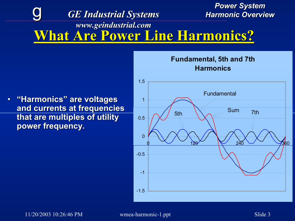
What Are Power Line Harmonics?What Are Power Line Harmonics?
•• “Harmonics” are voltages “Harmonics” are voltages and currents at frequencies and currents at frequencies that are multiples of utility that are multiples of utility power frequency.
Fundamental, 5th and 7th Harmonics
-1.5
-1
-0.5
0
0.5
1
1.5
0 120 240 360
Sum
Fundamental
7th5th
power frequency.

11/20/2003 10:26:46 PM wmea-harmonic-1.ppt Slide 4
gg GE Industrial SystemsGE Industrial Systemswww.geindustrial.comwww.geindustrial.com
Power SystemPower SystemHarmonic OverviewHarmonic Overview
Where Do Harmonics Come From?Where Do Harmonics Come From?•• Harmonic currents result from loads that Harmonic currents result from loads that
draw power in nondraw power in non--sinesine--wave format.wave format.•• These are soThese are so--called noncalled non--linear loads.linear loads.
11/20/2003 10:26:46 PM wmea-harmonic-1.ppt Slide 5
gg GE Industrial SystemsGE Industrial Systemswww.geindustrial.comwww.geindustrial.com
Power SystemPower SystemHarmonic OverviewHarmonic Overview
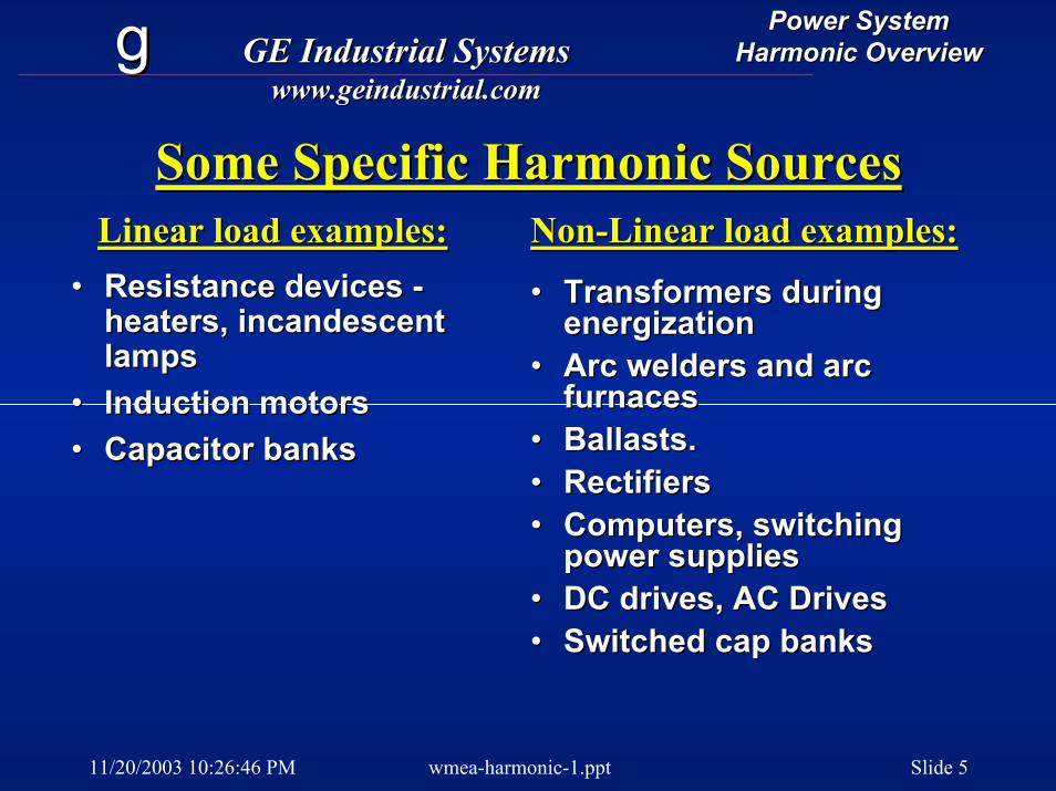
Some Specific Harmonic SourcesSome Specific Harmonic Sources
•• Resistance devices Resistance devices --heaters, incandescent heaters, incandescent lampslamps
•• Induction motorsInduction motors•• Capacitor banksCapacitor banks
•• Transformers during Transformers during energizationenergization
•• Arc welders and arc Arc welders and arc furnacesfurnaces
•• Ballasts.Ballasts.•• RectifiersRectifiers•• Computers, switching Computers, switching
power suppliespower supplies•• DC drives, AC DrivesDC drives, AC Drives•• Switched cap banksSwitched cap banks
Linear load examples:Linear load examples: NonNon--Linear load examples:Linear load examples:
11/20/2003 10:26:46 PM wmea-harmonic-1.ppt Slide 6
gg GE Industrial SystemsGE Industrial Systemswww.geindustrial.comwww.geindustrial.com
Power SystemPower SystemHarmonic OverviewHarmonic Overview
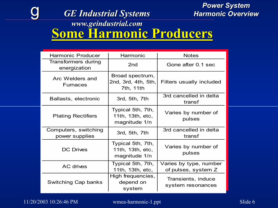
Some Harmonic ProducersSome Harmonic ProducersHarmonic Producer Harmonic NotesTransformers during
energization2nd Gone after 0.1 sec
Arc Welders and Furnaces
Broad spectrum, 2nd, 3rd, 4th, 5th,
7th, 11thFilters usually included
Ballasts, electronic 3rd, 5th, 7th 3rd cancelled in delta transf
Plating RectifiersTypical 5th, 7th, 11th, 13th, etc, magnitude 1/n
Varies by number of pulses
Computers, switching power supplies
3rd, 5th, 7th 3rd cancelled in delta transf
DC DrivesTypical 5th, 7th, 11th, 13th, etc, magnitude 1/n
Varies by number of pulses
AC drives Typical 5th, 7th, 11th, 13th, etc,
Varies by type, number of pulses, system Z
Switching Cap banksHigh frequencies,
depend on system
Transients, induce system resonances
11/20/2003 10:26:46 PM wmea-harmonic-1.ppt Slide 7
gg GE Industrial SystemsGE Industrial Systemswww.geindustrial.comwww.geindustrial.com
Power SystemPower SystemHarmonic OverviewHarmonic Overview
Why Worry?Why Worry?OR OR -- What makes Power system Harmonics so bad?What makes Power system Harmonics so bad?
•• Capacitors can blow from Capacitors can blow from overvoltageovervoltage
•• Drives can trip offlineDrives can trip offline•• Transformers can overheat Transformers can overheat --
possibly to destructionpossibly to destruction•• Motors will heat moreMotors will heat more•• Ballasts can popBallasts can pop•• Electronics can malfunctionElectronics can malfunction
11/20/2003 10:26:46 PM wmea-harmonic-1.ppt Slide 8
gg GE Industrial SystemsGE Industrial Systemswww.geindustrial.comwww.geindustrial.com
Power SystemPower SystemHarmonic OverviewHarmonic Overview
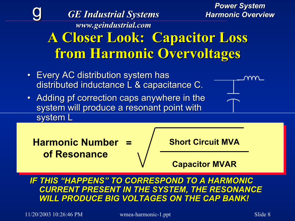
A Closer Look: Capacitor Loss A Closer Look: Capacitor Loss from Harmonic Overvoltagesfrom Harmonic Overvoltages
Harmonic Numberof Resonance
= Short Circuit MVA
Capacitor MVAR
•• Every AC distribution system has Every AC distribution system has distributed inductance L & capacitance C.distributed inductance L & capacitance C.
•• Adding pf correction caps anywhere in the Adding pf correction caps anywhere in the system will produce a resonant point with system will produce a resonant point with system Lsystem L
IF THIS “HAPPENS” TO CORRESPOND TO A HARMONIC IF THIS “HAPPENS” TO CORRESPOND TO A HARMONIC CURRENT PRESENT IN THE SYSTEM, THE RESONANCE CURRENT PRESENT IN THE SYSTEM, THE RESONANCE WILL PRODUCE BIG VOLTAGES ON THE CAP BANK!WILL PRODUCE BIG VOLTAGES ON THE CAP BANK!
11/20/2003 10:26:46 PM wmea-harmonic-1.ppt Slide 9
gg GE Industrial SystemsGE Industrial Systemswww.geindustrial.comwww.geindustrial.com
Power SystemPower SystemHarmonic OverviewHarmonic Overview
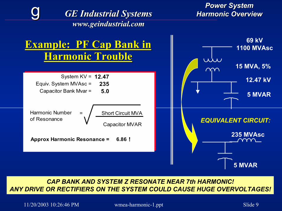
Example: PF Cap Bank in Example: PF Cap Bank in Harmonic Trouble
69 kV1100 MVAsc
15 MVA, 5%
5 MVAR
12.47 kV
5 MVAR
Harmonic Trouble
System KV = 12.47Equiv. System MVAsc = 235
Capacitor Bank Mvar = 5.0
Approx Harmonic Resonance = 6.86 !
Harmonic Numberof Resonance
= Short Circuit MVA
Capacitor MVAREQUIVALENT CIRCUIT:
235 MVAsc
CAP BANK AND SYSTEM Z RESONATE NEAR 7th HARMONIC!ANY DRIVE OR RECTIFIERS ON THE SYSTEM COULD CAUSE HUGE OVERVOLTAGES!
11/20/2003 10:26:46 PM wmea-harmonic-1.ppt Slide 10
gg GE Industrial SystemsGE Industrial Systemswww.geindustrial.comwww.geindustrial.com
Power SystemPower SystemHarmonic OverviewHarmonic Overview
Symptoms of Capacitor Series ResonanceSymptoms of Capacitor Series Resonance
•• Voltages across caps measure Voltages across caps measure higher than 10% over nameplate higher than 10% over nameplate rating, scope shows high peaks.rating, scope shows high peaks.
Be sure to use TrueBe sure to use True--RMS meterRMS meterOverOver--voltages can come and go with voltages can come and go with operation of harmonic producing operation of harmonic producing equipment.equipment.
•• Capacitor “Cans” are swollenCapacitor “Cans” are swollen•• Cap Fuses blow, cans failCap Fuses blow, cans fail
11/20/2003 10:26:46 PM wmea-harmonic-1.ppt Slide 11
gg GE Industrial SystemsGE Industrial Systemswww.geindustrial.comwww.geindustrial.com
Power SystemPower SystemHarmonic OverviewHarmonic Overview
Fixing System Resonance ProblemsFixing System Resonance Problems
•• Experiment or calculate to verify Experiment or calculate to verify problemproblem
Calculate using simplified approachCalculate using simplified approachTemporarily remove caps and Temporarily remove caps and observe effect.observe effect.
•• Remove proven offending cap banksRemove proven offending cap banks•• OR, Change size of bankOR, Change size of bank•• OR, Tune the bank with inductorsOR, Tune the bank with inductors

11/20/2003 10:26:46 PM wmea-harmonic-1.ppt Slide 12
gg GE Industrial SystemsGE Industrial Systemswww.geindustrial.comwww.geindustrial.com
Power SystemPower SystemHarmonic OverviewHarmonic Overview
Example Power SystemExample Power System
PLANT
CONVEYOR
HV UTILITY
MV DISTRIB
EXCAVATORSE
C
D
F
A
11/20/2003 10:26:46 PM wmea-harmonic-1.ppt Slide 13
gg GE Industrial SystemsGE Industrial Systemswww.geindustrial.comwww.geindustrial.com
Power SystemPower SystemHarmonic OverviewHarmonic Overview
The P.F. Correction DilemmaThe P.F. Correction DilemmaA. Harmonic producers such as drives A. Harmonic producers such as drives
often need power factor correction.often need power factor correction.B. Naked capacitors will likely B. Naked capacitors will likely
resonate and cause problemsresonate and cause problems
11/20/2003 10:26:46 PM wmea-harmonic-1.ppt Slide 14
gg GE Industrial SystemsGE Industrial Systemswww.geindustrial.comwww.geindustrial.com
Power SystemPower SystemHarmonic OverviewHarmonic Overview
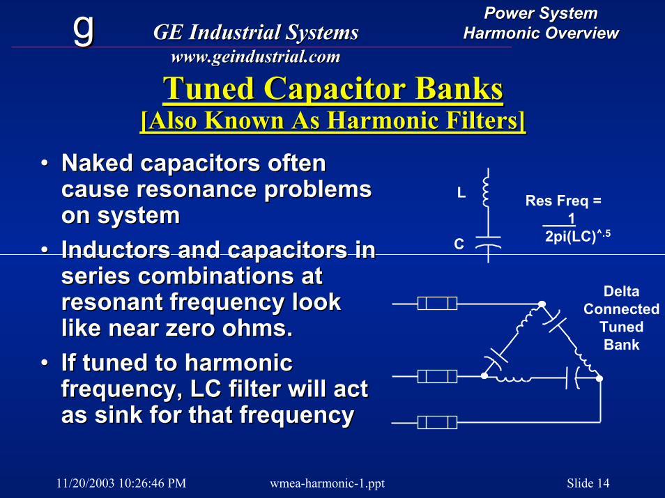
Tuned Capacitor BanksTuned Capacitor Banks[Also Known As Harmonic Filters][Also Known As Harmonic Filters]
•• Naked capacitors often Naked capacitors often cause resonance problems cause resonance problems on systemon system
•• Inductors and capacitors in Inductors and capacitors in series combinations at series combinations at resonant frequency look resonant frequency look like near zero ohms.like near zero ohms.
•• If tuned to harmonic If tuned to harmonic frequency, LC filter will act frequency, LC filter will act as sink for that frequency
L Res Freq = 1
2pi(LC)^.5C
as sink for that frequency
DeltaConnected
TunedBank
11/20/2003 10:26:46 PM wmea-harmonic-1.ppt Slide 15
gg GE Industrial SystemsGE Industrial Systemswww.geindustrial.comwww.geindustrial.com
Power SystemPower SystemHarmonic OverviewHarmonic Overview
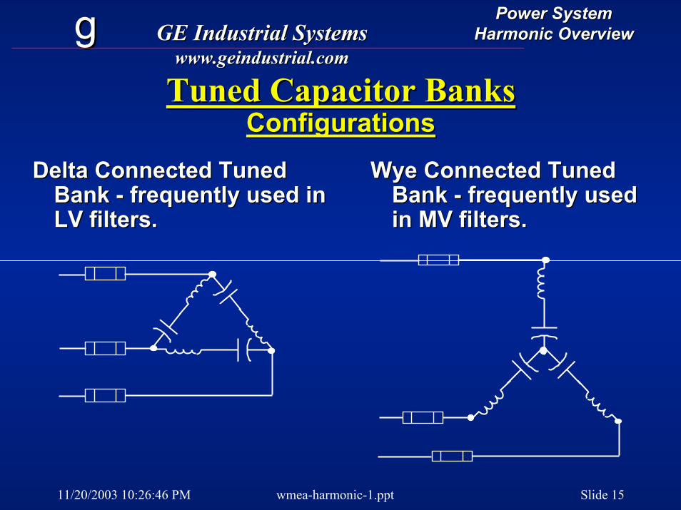
Tuned Capacitor BanksTuned Capacitor BanksConfigurationsConfigurations
Delta Connected Tuned Delta Connected Tuned Bank Bank -- frequently used in frequently used in LV filters.
Wye Connected Tuned Wye Connected Tuned Bank Bank -- frequently used frequently used in MV filters.LV filters. in MV filters.
11/20/2003 10:26:46 PM wmea-harmonic-1.ppt Slide 16
gg GE Industrial SystemsGE Industrial Systemswww.geindustrial.comwww.geindustrial.com
Power SystemPower SystemHarmonic OverviewHarmonic Overview
Harmonic FiltersHarmonic Filters
•• Medium voltage or low voltageMedium voltage or low voltage•• Tune to below desired trap Tune to below desired trap
frequency [example, 4.7th]frequency [example, 4.7th]•• Rising temps move up resonanceRising temps move up resonance•• Filter LC is in parallel with system z Filter LC is in parallel with system z --
causing ANOTHER resonant pointcausing ANOTHER resonant point•• New parallel resonant point is New parallel resonant point is
hopefully not on critical frequencieshopefully not on critical frequencies
11/20/2003 10:26:46 PM wmea-harmonic-1.ppt Slide 17
gg GE Industrial SystemsGE Industrial Systemswww.geindustrial.comwww.geindustrial.com
Power SystemPower SystemHarmonic OverviewHarmonic Overview
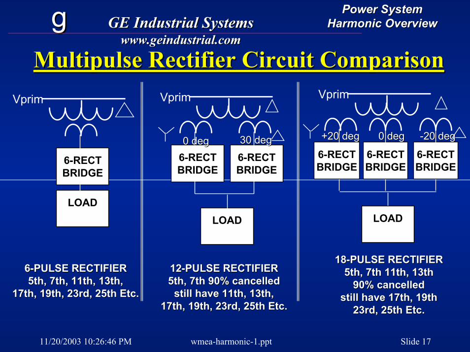
Multipulse Rectifier Circuit ComparisonMultipulse Rectifier Circuit Comparison
66--PULSE RECTIFIERPULSE RECTIFIER5th, 7th, 11th, 13th,5th, 7th, 11th, 13th,
17th, 19th, 23rd, 25th Etc.17th, 19th, 23rd, 25th Etc.
Vprim
LOADLOAD
66--RECTRECTBRIDGEBRIDGE
66--RECTRECTBRIDGEBRIDGE
0 deg0 deg 30 deg30 deg
1212--PULSE RECTIFIERPULSE RECTIFIER5th, 7th 90% cancelled5th, 7th 90% cancelled
still have 11th, 13th,still have 11th, 13th,17th, 19th, 23rd, 25th Etc.17th, 19th, 23rd, 25th Etc.
LOADLOAD
Vprim
66--RECTRECTBRIDGEBRIDGE
66--RECTRECTBRIDGEBRIDGE
66--RECTRECTBRIDGEBRIDGE
+20 deg+20 deg 0 deg0 deg --20 deg20 deg
Vprim
66--RECTRECTBRIDGEBRIDGE
LOADLOAD
1818--PULSE RECTIFIERPULSE RECTIFIER5th, 7th 11th, 13th5th, 7th 11th, 13th
90% cancelled90% cancelledstill have 17th, 19thstill have 17th, 19th
23rd, 25th Etc.23rd, 25th Etc.
11/20/2003 10:26:46 PM wmea-harmonic-1.ppt Slide 18
gg GE Industrial SystemsGE Industrial Systemswww.geindustrial.comwww.geindustrial.com
Power SystemPower SystemHarmonic OverviewHarmonic Overview
Plating RectifiersPlating Rectifiers
•• Power range 1Power range 1--10 MVA10 MVA•• Thyristor [SCR] phase controlledThyristor [SCR] phase controlled•• Frequently 12 pulse configuration to Frequently 12 pulse configuration to
cancel 5th and 7th harmonicscancel 5th and 7th harmonics•• Filters are on transformer primary Filters are on transformer primary
side.side.•• Small 5th and 7th plus 11th and 13th Small 5th and 7th plus 11th and 13th
filters.filters.
11/20/2003 10:26:46 PM wmea-harmonic-1.ppt Slide 19
gg GE Industrial SystemsGE Industrial Systemswww.geindustrial.comwww.geindustrial.com
Power SystemPower SystemHarmonic OverviewHarmonic Overview
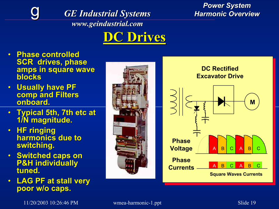
DC DrivesDC Drives
A B C A B C
A B C A B CPhase
Voltage
PhaseCurrents
Square Waves Currents
M
DC Rectified Excavator Drive
•• Phase controlled Phase controlled SCR drives, phase SCR drives, phase amps in square wave amps in square wave blocksblocks
•• Usually have PF Usually have PF comp and Filters comp and Filters onboard.onboard.
•• Typical 5th, 7th etc at Typical 5th, 7th etc at 1/N magnitude. 1/N magnitude.
•• HF ringing HF ringing harmonics due to harmonics due to switching.switching.
•• Switched caps on Switched caps on P&H individually P&H individually tuned.tuned.
•• LAG PF at stall very LAG PF at stall very poor w/o caps.poor w/o caps.
11/20/2003 10:26:46 PM wmea-harmonic-1.ppt Slide 20
gg GE Industrial SystemsGE Industrial Systemswww.geindustrial.comwww.geindustrial.com
Power SystemPower SystemHarmonic OverviewHarmonic Overview
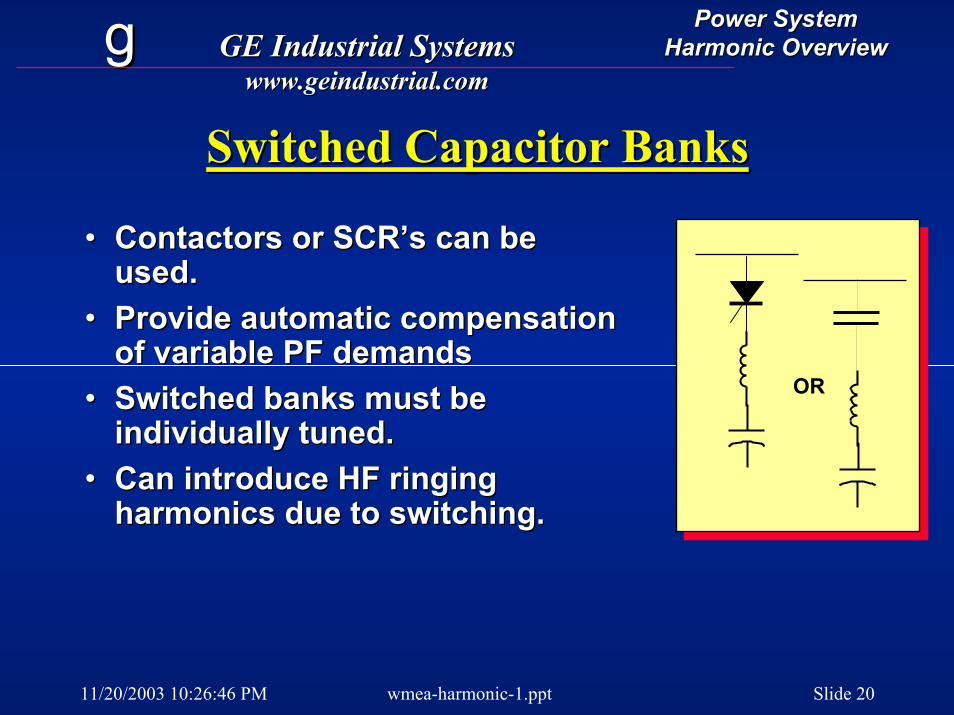
Switched Capacitor BanksSwitched Capacitor Banks
OR
•• Contactors or SCR’s can be Contactors or SCR’s can be used.used.
•• Provide automatic compensation Provide automatic compensation of variable PF demandsof variable PF demands
•• Switched banks must be Switched banks must be individually tuned.individually tuned.
•• Can introduce HF ringing Can introduce HF ringing harmonics due to switching.harmonics due to switching.
11/20/2003 10:26:46 PM wmea-harmonic-1.ppt Slide 21
gg GE Industrial SystemsGE Industrial Systemswww.geindustrial.comwww.geindustrial.com
Power SystemPower SystemHarmonic OverviewHarmonic Overview
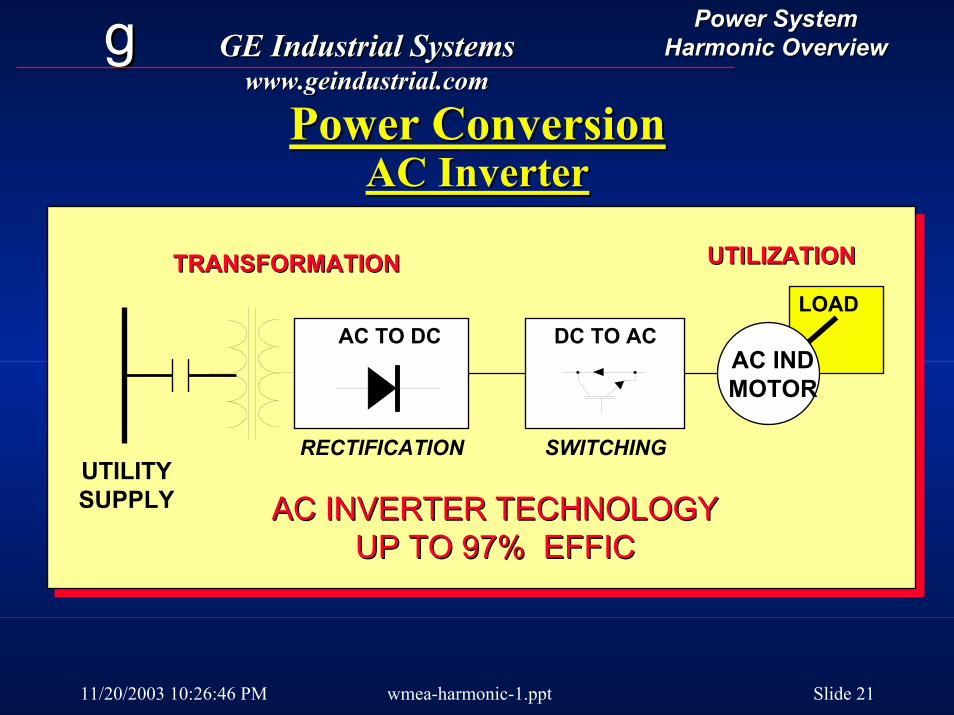
Power ConversionPower ConversionAC InverterAC Inverter
TRANSFORMATIONTRANSFORMATION
UTILITYSUPPLY
RECTIFICATION
AC TO DC
SWITCHING
DC TO ACLOAD
UTILIZATIONUTILIZATION
AC INDMOTOR
AC INVERTER TECHNOLOGYAC INVERTER TECHNOLOGYUP TO 97% EFFICUP TO 97% EFFIC
11/20/2003 10:26:46 PM wmea-harmonic-1.ppt Slide 22
gg GE Industrial SystemsGE Industrial Systemswww.geindustrial.comwww.geindustrial.com
Power SystemPower SystemHarmonic OverviewHarmonic Overview
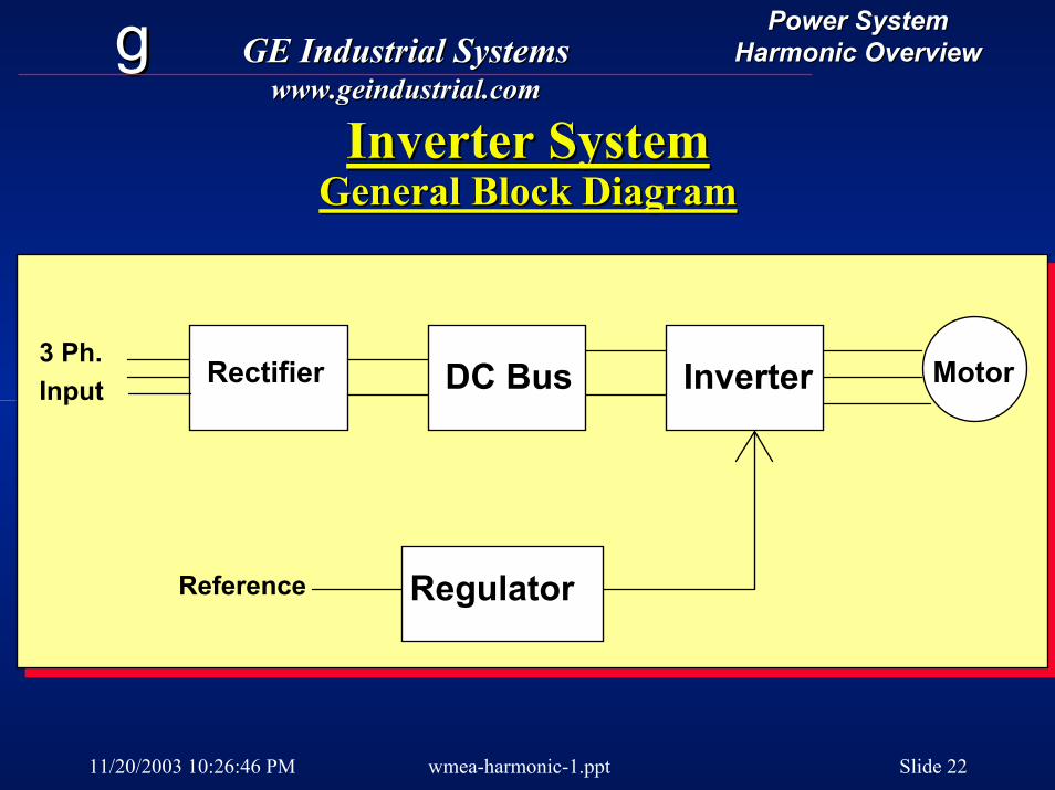
Inverter SystemInverter SystemGeneral Block DiagramGeneral Block Diagram
MotorInverterDC BusRectifier
RegulatorReference
3 Ph.Input
11/20/2003 10:26:46 PM wmea-harmonic-1.ppt Slide 23
gg GE Industrial SystemsGE Industrial Systemswww.geindustrial.comwww.geindustrial.com
Power SystemPower SystemHarmonic OverviewHarmonic Overview
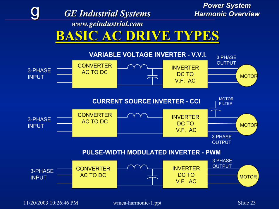
BASIC AC DRIVE TYPESBASIC AC DRIVE TYPES
INVERTERDC TO
V.F. ACMOTOR
3 PHASEOUTPUT
VARIABLE VOLTAGE INVERTER - V.V.I.CONVERTER
AC TO DC3-PHASEINPUT
CURRENT SOURCE INVERTER - CCI
CONVERTERAC TO DC3-PHASE
INPUT
3 PHASEOUTPUT
INVERTERDC TOV.F. AC
MOTORFILTER
MOTOR
PULSE-WIDTH MODULATED INVERTER - PWM
MOTOR
CONVERTERAC TO DC
3-PHASEINPUT
INVERTERDC TO
V.F. AC
3 PHASEOUTPUT
11/20/2003 10:26:46 PM wmea-harmonic-1.ppt Slide 24
gg GE Industrial SystemsGE Industrial Systemswww.geindustrial.comwww.geindustrial.com
Power SystemPower SystemHarmonic OverviewHarmonic Overview
ACAC--VFD Current Source DrivesVFD Current Source Drives•• All have phaseAll have phase--controlled front ends.controlled front ends.•• DC Link inductors keep current DC Link inductors keep current
continuouscontinuous•• Inverter switches curent to the motor Inverter switches curent to the motor
phases.phases.•• Used for large induction or sync Used for large induction or sync
motorsmotors•• Looks like a DC drive to the power Looks like a DC drive to the power
line, with similar harmonics.line, with similar harmonics.
11/20/2003 10:26:46 PM wmea-harmonic-1.ppt Slide 25
gg GE Industrial SystemsGE Industrial Systemswww.geindustrial.comwww.geindustrial.com
Power SystemPower SystemHarmonic OverviewHarmonic Overview
Variable DCBus
SynchronousMotor
Inverter(SCR)
ControlledRectifier
AC Input
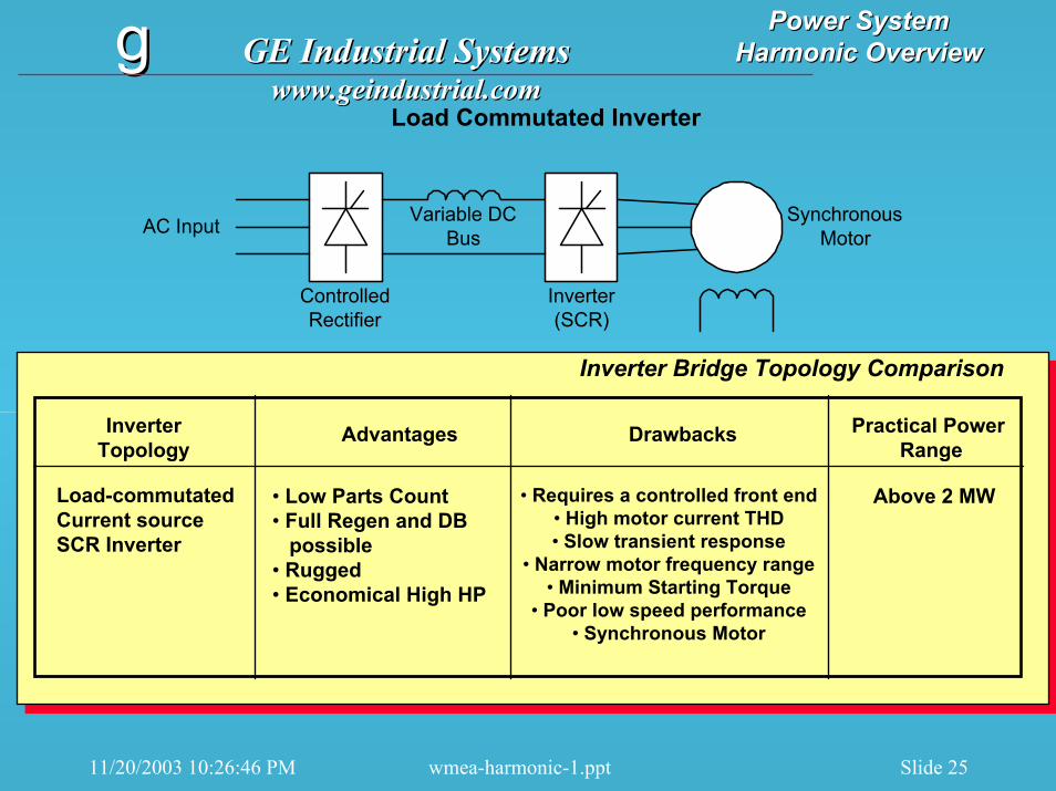
Load Commutated Inverter
InverterTopology
Advantages Drawbacks Practical Power Range
Load-commutatedCurrent sourceSCR Inverter
• Low Parts Count• Full Regen and DB
possible• Rugged• Economical High HP
• Requires a controlled front end• High motor current THD• Slow transient response
• Narrow motor frequency range• Minimum Starting Torque
• Poor low speed performance• Synchronous Motor
Above 2 MW
Inverter Bridge Topology Comparison
11/20/2003 10:26:46 PM wmea-harmonic-1.ppt Slide 26
gg GE Industrial SystemsGE Industrial Systemswww.geindustrial.comwww.geindustrial.com
Power SystemPower SystemHarmonic OverviewHarmonic Overview
Variable DCBus
Inverter(GTO)
ControlledRectifier
AC Input InductionMotor
Motor FilterCapacitors
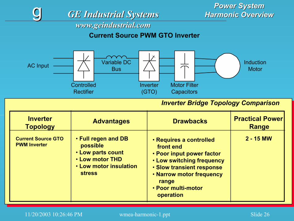
Current Source PWM GTO Inverter
InverterTopology
Advantages Drawbacks Practical Power Range
Current Source GTOPWM Inverter
• Full regen and DB possible
• Low parts count• Low motor THD• Low motor insulation
stress
• Requires a controlledfront end
• Poor input power factor• Low switching frequency• Slow transient response• Narrow motor frequency
range• Poor multi-motor
operation
2 - 15 MW
Inverter Bridge Topology Comparison
11/20/2003 10:26:46 PM wmea-harmonic-1.ppt Slide 27
gg GE Industrial SystemsGE Industrial Systemswww.geindustrial.comwww.geindustrial.com
Power SystemPower SystemHarmonic OverviewHarmonic Overview
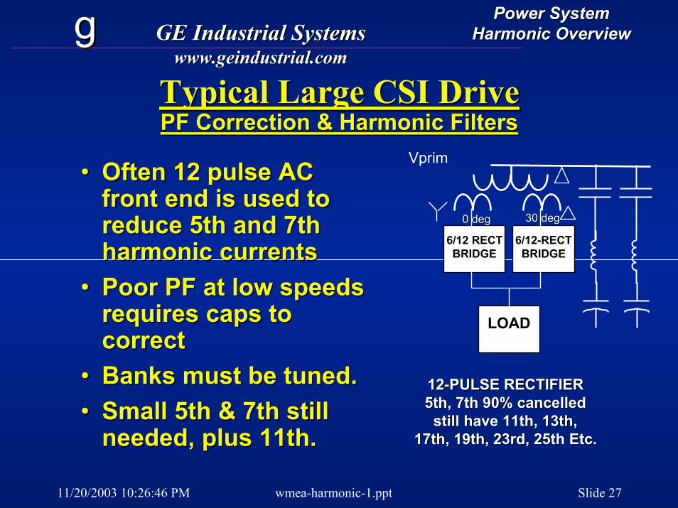
Typical Large CSI DriveTypical Large CSI DrivePF Correction & Harmonic FiltersPF Correction & Harmonic Filters
•• Often 12 pulse AC Often 12 pulse AC front end is used to front end is used to reduce 5th and 7th reduce 5th and 7th harmonic currentsharmonic currents
•• Poor PF at low speeds Poor PF at low speeds requires caps to requires caps to correctcorrect
•• Banks must be tuned.Banks must be tuned.•• Small 5th & 7th still Small 5th & 7th still
needed, plus 11th.
Vprim
LOADLOAD
6/12 RECT6/12 RECTBRIDGEBRIDGE
6/126/12--RECTRECTBRIDGEBRIDGE
0 deg0 deg 30 deg30 deg
1212--PULSE RECTIFIERPULSE RECTIFIER5th, 7th 90% cancelled5th, 7th 90% cancelled
still have 11th, 13th,still have 11th, 13th,17th, 19th, 23rd, 25th Etc.17th, 19th, 23rd, 25th Etc.needed, plus 11th.

11/20/2003 10:26:46 PM wmea-harmonic-1.ppt Slide 28
gg GE Industrial SystemsGE Industrial Systemswww.geindustrial.comwww.geindustrial.com
Power SystemPower SystemHarmonic OverviewHarmonic Overview
AC PWM DrivesAC PWM Drives
•• The most frequent AC drives in use The most frequent AC drives in use today.today.
•• LV or MV drives LV or MV drives -- usually use diode usually use diode front ends.front ends.
•• Create unique PF and harmonic Create unique PF and harmonic problems.problems.

11/20/2003 10:26:46 PM wmea-harmonic-1.ppt Slide 29
gg GE Industrial SystemsGE Industrial Systemswww.geindustrial.comwww.geindustrial.com
Power SystemPower SystemHarmonic OverviewHarmonic Overview
Utility ConsiderationsUtility ConsiderationsUTILITY
MDrive
•• Stiffness of supplyStiffness of supply•• Utility power level variationsUtility power level variations•• “Quality” of power as received“Quality” of power as received•• Restrictions on power quality Restrictions on power quality
effects by new installation [power effects by new installation [power factor, harmonics]factor, harmonics]
•• Impact of new loads onImpact of new loads onexisting system.existing system.
11/20/2003 10:26:46 PM wmea-harmonic-1.ppt Slide 30
gg GE Industrial SystemsGE Industrial Systemswww.geindustrial.comwww.geindustrial.com
Power SystemPower SystemHarmonic OverviewHarmonic Overview
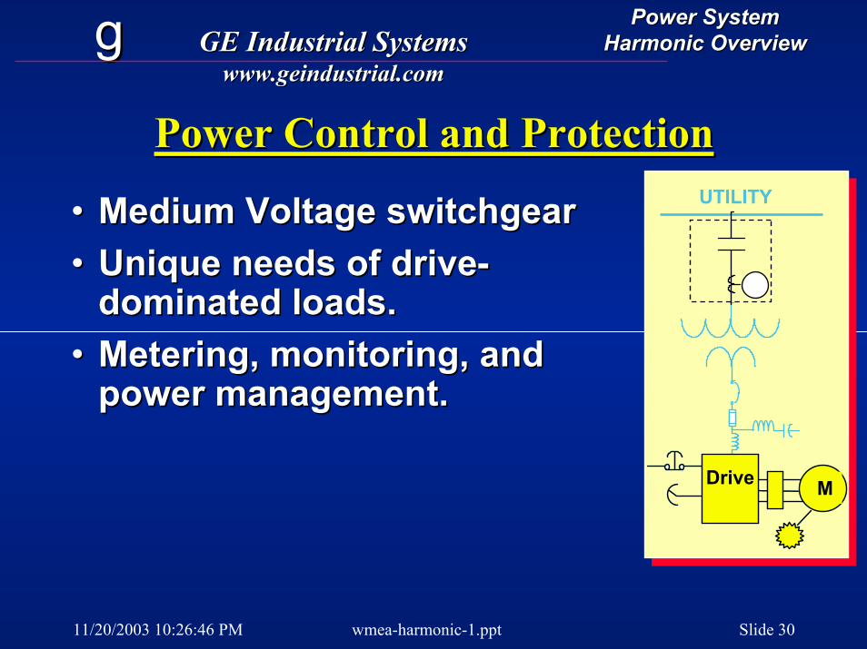
Power Control and ProtectionPower Control and ProtectionUTILITY
MACDrive MDrive
•• Medium Voltage switchgearMedium Voltage switchgear•• Unique needs of driveUnique needs of drive--
dominated loads.dominated loads.•• Metering, monitoring, and Metering, monitoring, and
power management.power management.
11/20/2003 10:26:46 PM wmea-harmonic-1.ppt Slide 31
gg GE Industrial SystemsGE Industrial Systemswww.geindustrial.comwww.geindustrial.com
Power SystemPower SystemHarmonic OverviewHarmonic Overview
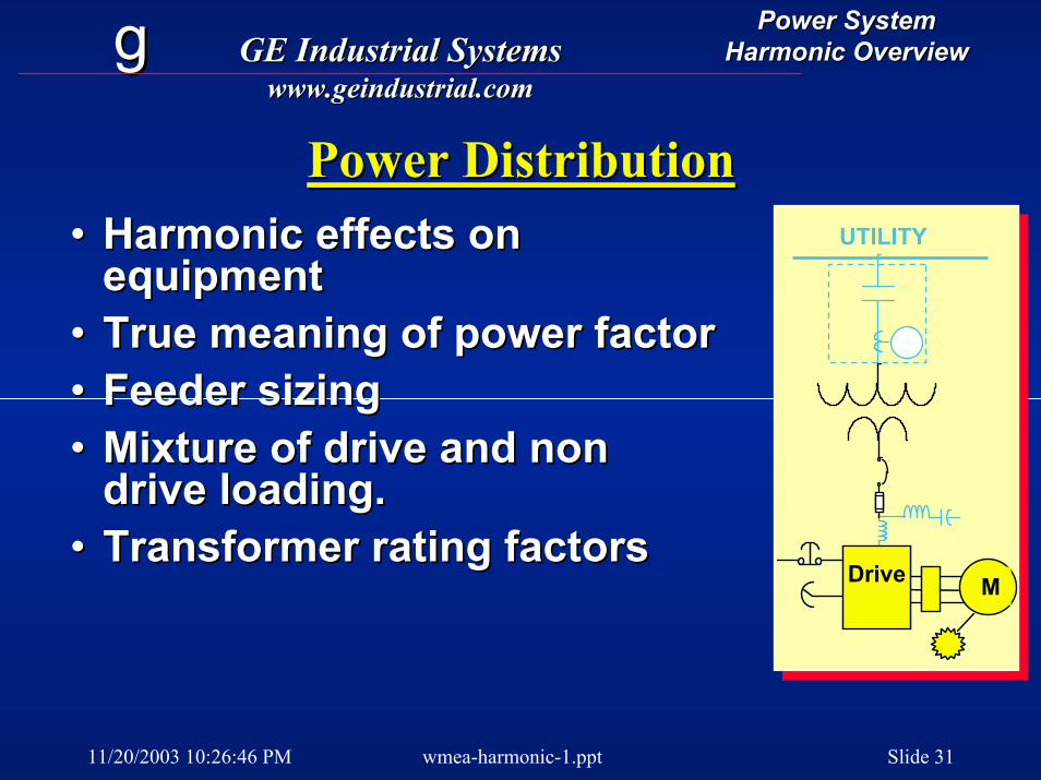
Power DistributionPower DistributionUTILITY
MACDrive MDrive
•• Harmonic effects on Harmonic effects on equipmentequipment
•• True meaning of power factorTrue meaning of power factor•• Feeder sizingFeeder sizing•• Mixture of drive and non Mixture of drive and non
drive loading.drive loading.•• Transformer rating factorsTransformer rating factors

11/20/2003 10:26:46 PM wmea-harmonic-1.ppt Slide 32
gg GE Industrial SystemsGE Industrial Systemswww.geindustrial.comwww.geindustrial.com
Power SystemPower SystemHarmonic OverviewHarmonic Overview
Power Quality IssuesPower Quality Issues•• Power disturbances on existing Power disturbances on existing
system.system.•• Injection of harmonics Injection of harmonics --
The problem & true impactThe problem & true impactSpecs, recommendations & Specs, recommendations & regulations [IEEEregulations [IEEE--519 & others]519 & others]Rational solutionsRational solutions
•• Economic tradeoffs.
UTILITY
MACDrive MDriveEconomic tradeoffs.
11/20/2003 10:26:46 PM wmea-harmonic-1.ppt Slide 33
gg GE Industrial SystemsGE Industrial Systemswww.geindustrial.comwww.geindustrial.com
Power SystemPower SystemHarmonic OverviewHarmonic Overview
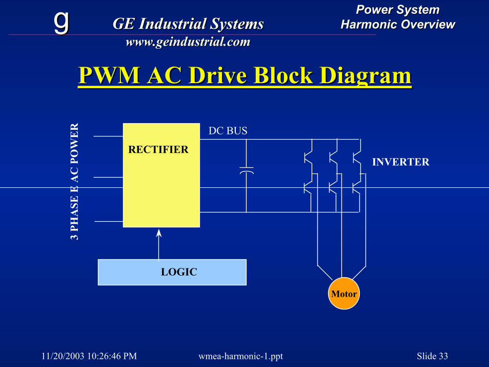
PWM AC Drive Block DiagramPWM AC Drive Block Diagram3
PHA
SE E
AC
PO
WE
R DC BUS
LOGIC
RECTIFIERINVERTER
Motor
11/20/2003 10:26:46 PM wmea-harmonic-1.ppt Slide 34
gg GE Industrial SystemsGE Industrial Systemswww.geindustrial.comwww.geindustrial.com
Power SystemPower SystemHarmonic OverviewHarmonic Overview
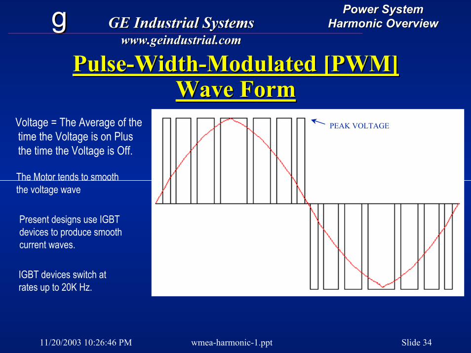
PulsePulse--WidthWidth--Modulated [PWM] Modulated [PWM] Wave FormWave Form
PEAK VOLTAGEVoltage = The Average of thetime the Voltage is on Plusthe time the Voltage is Off.
The Motor tends to smooththe voltage wave
Present designs use IGBTdevices to produce smoothcurrent waves.
IGBT devices switch atrates up to 20K Hz.
11/20/2003 10:26:46 PM wmea-harmonic-1.ppt Slide 35
gg GE Industrial SystemsGE Industrial Systemswww.geindustrial.comwww.geindustrial.com
Power SystemPower SystemHarmonic OverviewHarmonic Overview
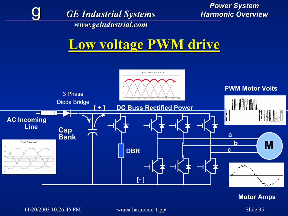
Low voltage PWM driveLow voltage PWM drive
Mc
AC IncomingLine
[ + ]
[- ]
Three Phase Input
-1.3
-0.8
-0.3
0.2
0.7
1.2
0 50 100 150 200 250 300 350 400
R e c t i f i e d 3 - P h a s e
0
0 . 2
0 . 4
0 . 6
0 . 8
1
1 . 2
0 5 0 1 0 0 1 5 0 2 0 0 2 5 0 3 0 0 3 5 0 4 0 0
CapBank
PWM Motor Volts3 Phase
Diode BridgeDC Buss Rectified Power
ab
DBR
Motor Amps
11/20/2003 10:26:46 PM wmea-harmonic-1.ppt Slide 36
gg GE Industrial SystemsGE Industrial Systemswww.geindustrial.comwww.geindustrial.com
Power SystemPower SystemHarmonic OverviewHarmonic Overview
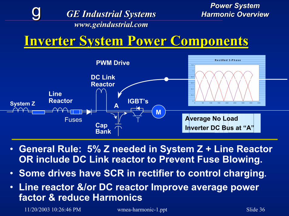
Inverter System Power ComponentsInverter System Power ComponentsR e c tif ie d 3 -P h a s e
0
0 .2
0 .4
0 .6
0 .8
1
1 .2
0 5 0 1 0 0 1 5 0 2 0 0 2 5 0 3 0 0 3 5 0 4 0 0
MSystem Z
LineReactor
PWM Drive
DC LinkReactor
CapBank
IGBT’sA
Fuses Average No LoadInverter DC Bus at “A”
• General Rule: 5% Z needed in System Z + Line Reactor OR include DC Link reactor to Prevent Fuse Blowing.
• Some drives have SCR in rectifier to control charging.• Line reactor &/or DC reactor Improve average power
factor & reduce Harmonics
11/20/2003 10:26:46 PM wmea-harmonic-1.ppt Slide 37
gg GE Industrial SystemsGE Industrial Systemswww.geindustrial.comwww.geindustrial.com
Power SystemPower SystemHarmonic OverviewHarmonic Overview
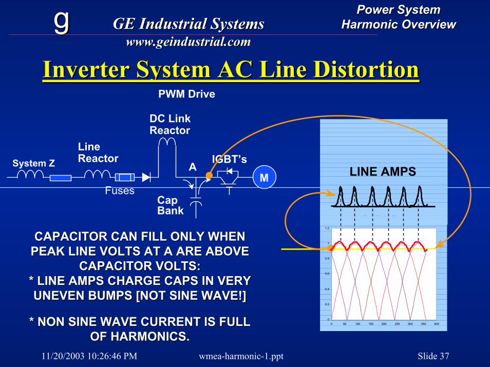
Inverter System AC Line DistortionInverter System AC Line Distortion
Rectified 3-Phase
0
0.2
0.4
0.6
0.8
1
1.2
0 50 100 150 200 250 300 350 400
MSystem Z
LineReactor
PWM Drive
DC LinkReactor
CapBank
IGBT’sA
Fuses
LINE AMPS
CAPACITOR CAN FILL ONLY WHEN CAPACITOR CAN FILL ONLY WHEN PEAK LINE VOLTS AT A ARE ABOVE PEAK LINE VOLTS AT A ARE ABOVE
CAPACITOR VOLTS:CAPACITOR VOLTS:* LINE AMPS CHARGE CAPS IN VERY * LINE AMPS CHARGE CAPS IN VERY UNEVEN BUMPS [NOT SINE WAVE!]UNEVEN BUMPS [NOT SINE WAVE!]
* NON SINE WAVE CURRENT IS FULL * NON SINE WAVE CURRENT IS FULL OF HARMONICS.OF HARMONICS.
11/20/2003 10:26:46 PM wmea-harmonic-1.ppt Slide 38
gg GE Industrial SystemsGE Industrial Systemswww.geindustrial.comwww.geindustrial.com
Power SystemPower SystemHarmonic OverviewHarmonic Overview
Displacement vs Real Power FactorDisplacement vs Real Power Factor
•• Drives are usually specified in Drives are usually specified in “displacement power factor”, DPF“displacement power factor”, DPF
•• DPF = cosine of phase angle between supply DPF = cosine of phase angle between supply volts and line amps.volts and line amps.
•• For diode front end PWM, DPF > .95For diode front end PWM, DPF > .95•• True PF = KW / KVATrue PF = KW / KVA•• True PF can be quite bad. PF =0.60 not True PF can be quite bad. PF =0.60 not
uncommon! Depends on Line Z.uncommon! Depends on Line Z.
11/20/2003 10:26:46 PM wmea-harmonic-1.ppt Slide 39
gg GE Industrial SystemsGE Industrial Systemswww.geindustrial.comwww.geindustrial.com
Power SystemPower SystemHarmonic OverviewHarmonic Overview
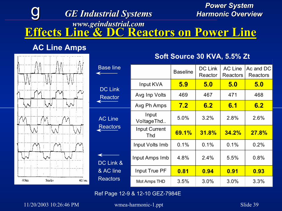
Effects Line & DC Reactors on Power LineEffects Line & DC Reactors on Power LineAC Line Amps
Ref Page 12-9 & 12-10 GEZ-7984E
Baseline DC Link Reactor
AC Line Reactors
Ac and DC Reactors
Input KVA 5.9 5.0 5.0 5.0Avg Inp Volts 469 467 471 468
Avg Ph Amps 7.2 6.2 6.1 6.2Input
VoItageThd.. 5.0% 3.2% 2.8% 2.6%
Input Current Thd 69.1% 31.8% 34.2% 27.8%
Input Volts Imb 0.1% 0.1% 0.1% 0.2%
Input Amps Imb 4.8% 2.4% 5.5% 0.8%
Input True PF 0.81 0.94 0.91 0.93Mot Amps THD 3.5% 3.0% 3.0% 3.3%
Soft Source 30 KVA, 5.5% Zt Base line
DC LinkReactor
AC LineReactors
DC Link && AC lineReactors
11/20/2003 10:26:46 PM wmea-harmonic-1.ppt Slide 40
gg GE Industrial SystemsGE Industrial Systemswww.geindustrial.comwww.geindustrial.com
Power SystemPower SystemHarmonic OverviewHarmonic Overview
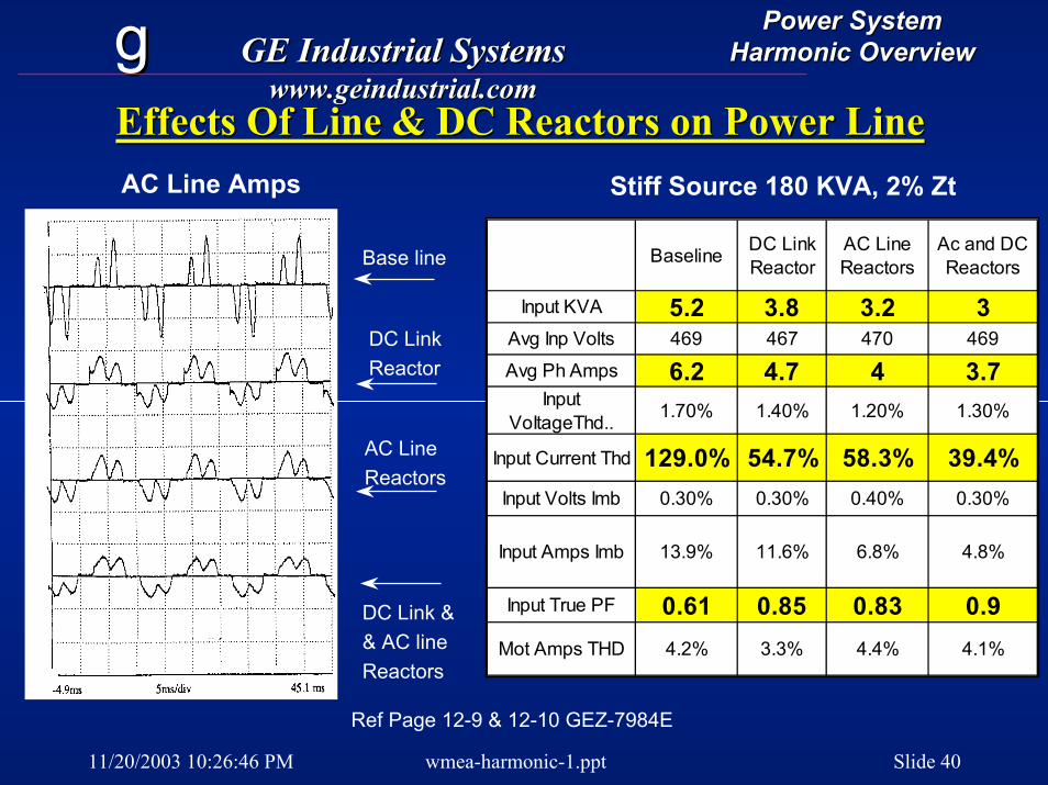
Effects Of Line & DC Reactors on Power LineEffects Of Line & DC Reactors on Power LineAC Line Amps Stiff Source 180 KVA, 2% Zt
Baseline DC Link Reactor
AC Line Reactors
Ac and DC Reactors
Input KVA 5.2 3.8 3.2 3Avg Inp Volts 469 467 470 469
Avg Ph Amps 6.2 4.7 4 3.7Input
VoItageThd.. 1.70% 1.40% 1.20% 1.30%
Input Current Thd 129.0% 54.7% 58.3% 39.4%Input Volts Imb 0.30% 0.30% 0.40% 0.30%
Input Amps Imb 13.9% 11.6% 6.8% 4.8%
Input True PF 0.61 0.85 0.83 0.9Mot Amps THD 4.2% 3.3% 4.4% 4.1%
Base line
DC LinkReactor
AC LineReactors
DC Link && AC lineReactors
Ref Page 12-9 & 12-10 GEZ-7984E
11/20/2003 10:26:46 PM wmea-harmonic-1.ppt Slide 41
gg GE Industrial SystemsGE Industrial Systemswww.geindustrial.comwww.geindustrial.com
Power SystemPower SystemHarmonic OverviewHarmonic Overview
Power System CompatibilityPower System Compatibility--Supply Supply
•• FastFast--acting current limiting AC line fuses acting current limiting AC line fuses protect input rectifiers and limit fault current.protect input rectifiers and limit fault current.
•• Added reactance in AC line or DC link is Added reactance in AC line or DC link is needed when feeder transformerneeded when feeder transformer kVAkVA is >10 is >10 times drive HP to prevent fuse blowing.times drive HP to prevent fuse blowing.
•• System reactance [native or added] System reactance [native or added] GREATLY reduces line KVA and harmonic GREATLY reduces line KVA and harmonic currentscurrents
11/20/2003 10:26:46 PM wmea-harmonic-1.ppt Slide 42
gg GE Industrial SystemsGE Industrial Systemswww.geindustrial.comwww.geindustrial.com
Power SystemPower SystemHarmonic OverviewHarmonic Overview
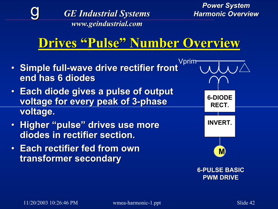
Drives “Pulse” Number OverviewDrives “Pulse” Number Overview
•• Simple fullSimple full--wave drive rectifier front wave drive rectifier front end has 6 diodesend has 6 diodes
•• Each diode gives a pulse of output Each diode gives a pulse of output voltage for every peak of 3voltage for every peak of 3--phase phase voltage.voltage.
•• Higher “pulse” drives use more Higher “pulse” drives use more diodes in rectifier section.diodes in rectifier section.
•• Each rectifier fed from own Each rectifier fed from own transformer secondarytransformer secondary
Vprim
M
66--DIODEDIODERECT.RECT.
INVERT.INVERT.
66--PULSE BASICPULSE BASICPWM DRIVEPWM DRIVE
11/20/2003 10:26:46 PM wmea-harmonic-1.ppt Slide 43
gg GE Industrial SystemsGE Industrial Systemswww.geindustrial.comwww.geindustrial.com
Power SystemPower SystemHarmonic OverviewHarmonic Overview
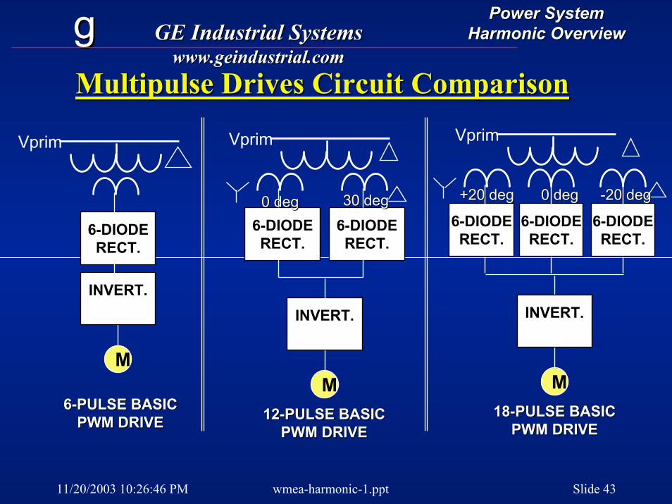
Multipulse Drives Circuit ComparisonMultipulse Drives Circuit Comparison
Vprim
M
INVERT.INVERT.
1212--PULSE BASICPULSE BASICPWM DRIVEPWM DRIVE
66--DIODEDIODERECT.RECT.
66--DIODEDIODERECT.RECT.
0 deg0 deg 30 deg30 deg
Vprim
M
66--DIODEDIODERECT.RECT.
INVERT.INVERT.
66--PULSE BASICPULSE BASICPWM DRIVEPWM DRIVE
M
INVERT.INVERT.
Vprim
66--DIODEDIODERECT.RECT.
66--DIODEDIODERECT.RECT.
66--DIODEDIODERECT.RECT.
+20 deg+20 deg 0 deg0 deg --20 deg20 deg
1818--PULSE BASICPULSE BASICPWM DRIVEPWM DRIVE
11/20/2003 10:26:46 PM wmea-harmonic-1.ppt Slide 44
gg GE Industrial SystemsGE Industrial Systemswww.geindustrial.comwww.geindustrial.com
Power SystemPower SystemHarmonic OverviewHarmonic Overview
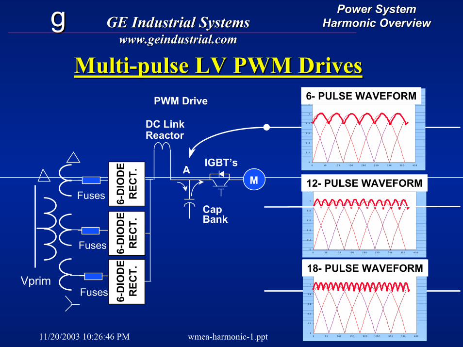
MultiMulti--pulse LV PWM Drivespulse LV PWM DrivesR e c tif ie d 3 -P h a s e
0
0 .2
0 .4
0 .6
0 .8
1
1 .2
0 5 0 1 0 0 1 5 0 2 0 0 2 5 0 3 0 0 3 5 0 4 0 0
6- PULSE WAVEFORMPWM Drive
MIGBT’s
A
DC LinkReactor
Fuses
Fuses
66 --D
IOD
ED
IOD
ER
ECT.
REC
T.66 --
DIO
DE
DIO
DE
REC
T.R
ECT.
66 --D
IOD
ED
IOD
ER
ECT.
REC
T.
R e c tif ie d 3 -P h a s e
0
0 .2
0 .4
0 .6
0 .8
1
1 .2
0 5 0 1 0 0 1 5 0 2 0 0 2 5 0 3 0 0 3 5 0 4 0 0
12- PULSE WAVEFORM
Vprim
CapBank
Fuses
R e c tif ie d 3 -P h a s e
0
0 .2
0 .4
0 .6
0 .8
1
1 .2
0 5 0 1 0 0 1 5 0 2 0 0 2 5 0 3 0 0 3 5 0 4 0 0
18- PULSE WAVEFORM
11/20/2003 10:26:46 PM wmea-harmonic-1.ppt Slide 45
gg GE Industrial SystemsGE Industrial Systemswww.geindustrial.comwww.geindustrial.com
Power SystemPower SystemHarmonic OverviewHarmonic Overview
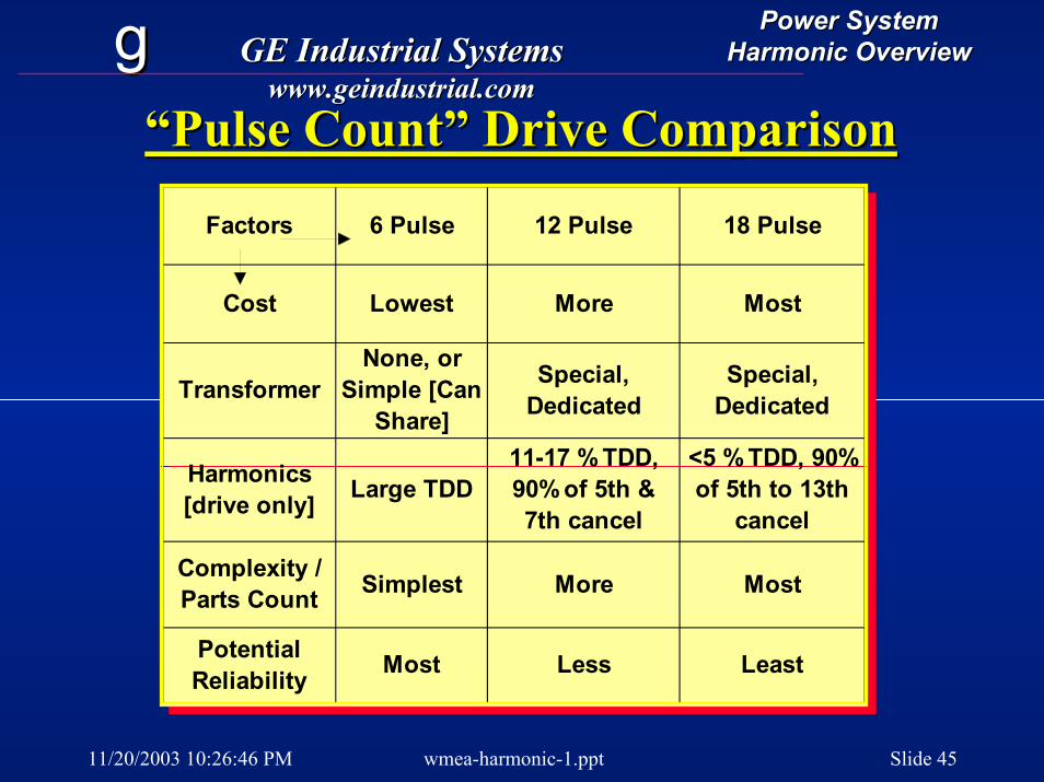
“Pulse Count” Drive Comparison“Pulse Count” Drive Comparison
Factors 6 Pulse 12 Pulse 18 Pulse
Cost Lowest More Most
TransformerNone, or
Simple [Can Share]
Special, Dedicated
Special, Dedicated
Harmonics [drive only] Large TDD
11-17 % TDD, 90% of 5th & 7th cancel
<5 % TDD, 90% of 5th to 13th
cancel
Complexity / Parts Count Simplest More Most
Potential Reliability Most Less Least
11/20/2003 10:26:46 PM wmea-harmonic-1.ppt Slide 46
gg GE Industrial SystemsGE Industrial Systemswww.geindustrial.comwww.geindustrial.com
Power SystemPower SystemHarmonic OverviewHarmonic Overview
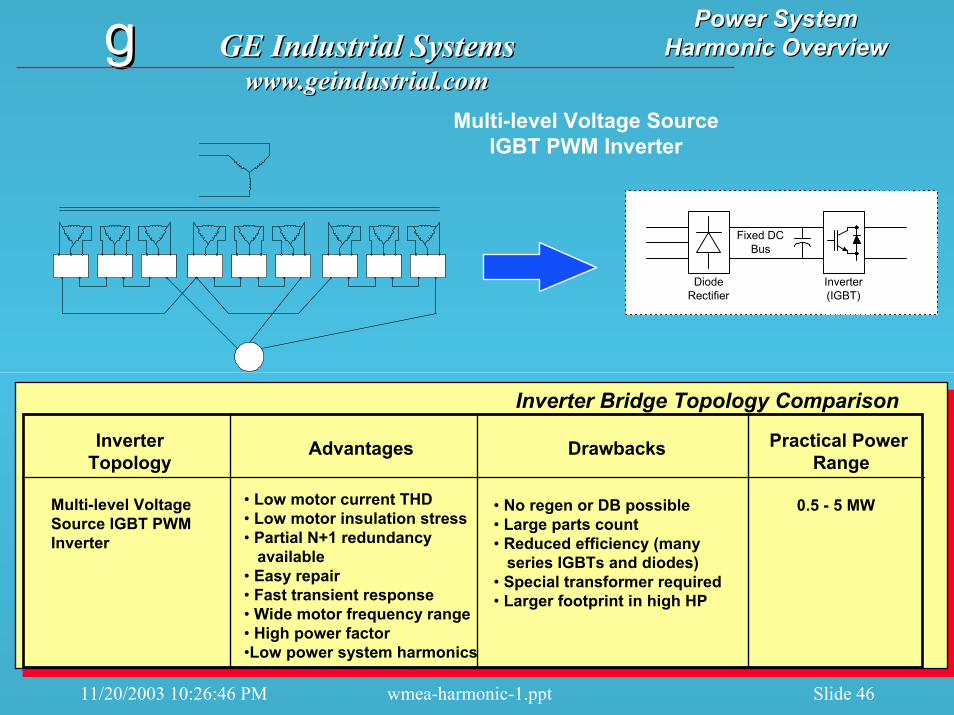
Multi-level Voltage SourceIGBT PWM Inverter
Fixed DCBus
Inverter(IGBT)
DiodeRectifier
InverterTopology
Advantages Drawbacks Practical Power Range
Multi-level Voltage Source IGBT PWM Inverter
• Low motor current THD• Low motor insulation stress• Partial N+1 redundancy
available• Easy repair• Fast transient response• Wide motor frequency range• High power factor•Low power system harmonics
• No regen or DB possible• Large parts count• Reduced efficiency (many
series IGBTs and diodes)• Special transformer required• Larger footprint in high HP
0.5 - 5 MW
Inverter Bridge Topology Comparison
11/20/2003 10:26:46 PM wmea-harmonic-1.ppt Slide 47
gg GE Industrial SystemsGE Industrial Systemswww.geindustrial.comwww.geindustrial.com
Power SystemPower SystemHarmonic OverviewHarmonic Overview
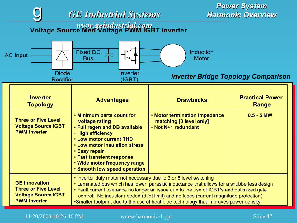
Fixed DCBus
Inverter(IGBT)
DiodeRectifier
AC Input InductionMotor
Voltage Source Med Voltage PWM IGBT Inverter
InverterTopology
Advantages Drawbacks Practical Power Range
Three or Five Level Voltage Source IGBT PWM Inverter
• Minimum parts count forvoltage rating
• Full regen and DB available• High efficiency• Low motor current THD• Low motor insulation stress• Easy repair• Fast transient response• Wide motor frequency range• Smooth low speed operation
• Inverter duty motor not necessary due to 3 or 5 level switching• Laminated bus which has lower parasitic inductance that allows for a snubberless design• Fault current tolerance no longer an issue due to the use of IGBT’s and optimized gate
control. No inductor needed (di/dt limit) and no fuses (current magnitude protection)•Smaller footprint due to the use of heat pipe technology that improves power density
0.5 - 5 MW• Motor termination impedancematching [3 level only]
• Not N+1 redundant
Inverter Bridge Topology Comparison
GE InnovationThree or Five Level Voltage Source IGBT PWM Inverter
11/20/2003 10:26:46 PM wmea-harmonic-1.ppt Slide 48
gg GE Industrial SystemsGE Industrial Systemswww.geindustrial.comwww.geindustrial.com
Power SystemPower SystemHarmonic OverviewHarmonic Overview
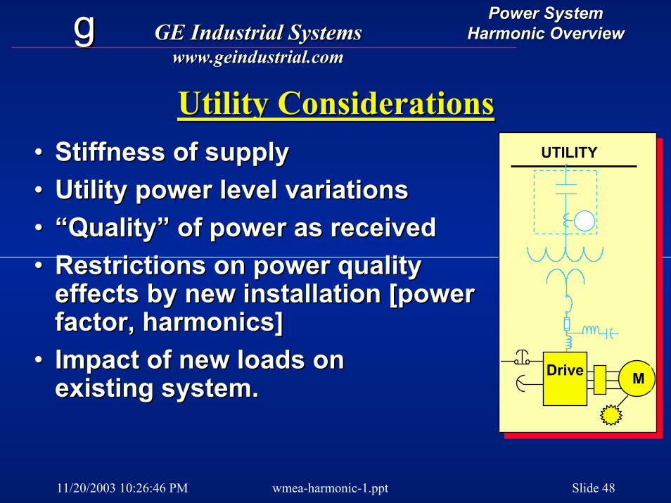
Utility ConsiderationsUtility ConsiderationsUTILITY
MDrive
•• Stiffness of supplyStiffness of supply•• Utility power level variationsUtility power level variations•• “Quality” of power as received“Quality” of power as received•• Restrictions on power quality Restrictions on power quality
effects by new installation [power effects by new installation [power factor, harmonics]factor, harmonics]
•• Impact of new loads onImpact of new loads onexisting system.existing system.

11/20/2003 10:26:46 PM wmea-harmonic-1.ppt Slide 49
gg GE Industrial SystemsGE Industrial Systemswww.geindustrial.comwww.geindustrial.com
Power SystemPower SystemHarmonic OverviewHarmonic Overview
Power Control and ProtectionPower Control and ProtectionUTILITY
MACDrive MDrive
•• Medium Voltage switchgearMedium Voltage switchgear•• Unique needs of driveUnique needs of drive--
dominated loads.dominated loads.•• Metering, monitoring, and Metering, monitoring, and
power management.power management.

11/20/2003 10:26:46 PM wmea-harmonic-1.ppt Slide 50
gg GE Industrial SystemsGE Industrial Systemswww.geindustrial.comwww.geindustrial.com
Power SystemPower SystemHarmonic OverviewHarmonic Overview
Power DistributionPower DistributionUTILITY
MACDrive MDrive
•• Harmonic effects on Harmonic effects on equipmentequipment
•• True meaning of power factorTrue meaning of power factor•• Feeder sizingFeeder sizing•• Mixture of drive and non Mixture of drive and non
drive loading.drive loading.•• Transformer rating factorsTransformer rating factors
11/20/2003 10:26:46 PM wmea-harmonic-1.ppt Slide 51
gg GE Industrial SystemsGE Industrial Systemswww.geindustrial.comwww.geindustrial.com
Power SystemPower SystemHarmonic OverviewHarmonic Overview
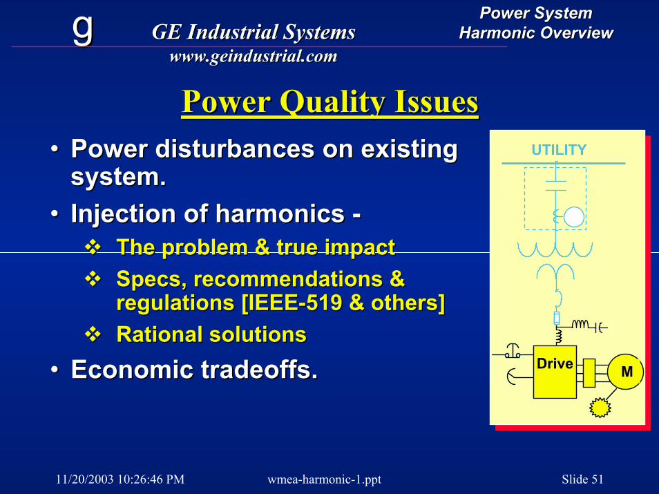
Power Quality IssuesPower Quality Issues•• Power disturbances on existing Power disturbances on existing
system.system.•• Injection of harmonics Injection of harmonics --
The problem & true impactThe problem & true impactSpecs, recommendations & Specs, recommendations & regulations [IEEEregulations [IEEE--519 & others]519 & others]Rational solutionsRational solutions
•• Economic tradeoffs.
UTILITY
MACDrive MDriveEconomic tradeoffs.
11/20/2003 10:26:46 PM wmea-harmonic-1.ppt Slide 52
gg GE Industrial SystemsGE Industrial Systemswww.geindustrial.comwww.geindustrial.com
Power SystemPower SystemHarmonic OverviewHarmonic Overview
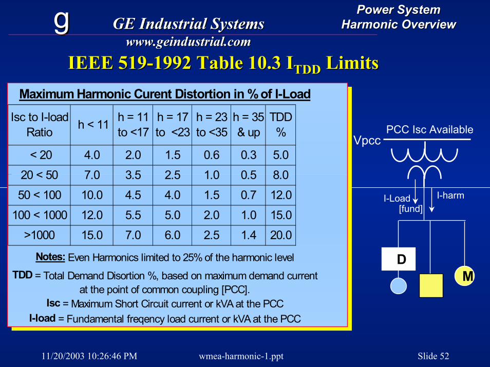
IEEE 519IEEE 519--1992 Table 10.3 I1992 Table 10.3 ITDDTDD LimitsLimitsMaximum Harmonic Curent Distortion in % of I-Load
Isc to I-load Ratio h < 11 h = 11
to <17h = 17 to <23
h = 23 to <35
h = 35 & up
TDD %
< 20 4.0 2.0 1.5 0.6 0.3 5.0
20 < 50 7.0 3.5 2.5 1.0 0.5 8.0
50 < 100 10.0 4.5 4.0 1.5 0.7 12.0
100 < 1000 12.0 5.5 5.0 2.0 1.0 15.0
>1000 15.0 7.0 6.0 2.5 1.4 20.0
Notes: Even Harmonics limited to 25% of the harmonic levelTDD = Total Demand Disortion %, based on maximum demand current
at the point of common coupling [PCC].Isc = Maximum Short Circuit current or kVA at the PCC
I-load = Fundamental freqency load current or kVA at the PCC
I-Load[fund]
PCC Isc Available
I-harm
Vpcc
DM
11/20/2003 10:26:46 PM wmea-harmonic-1.ppt Slide 53
gg GE Industrial SystemsGE Industrial Systemswww.geindustrial.comwww.geindustrial.com
Power SystemPower SystemHarmonic OverviewHarmonic Overview
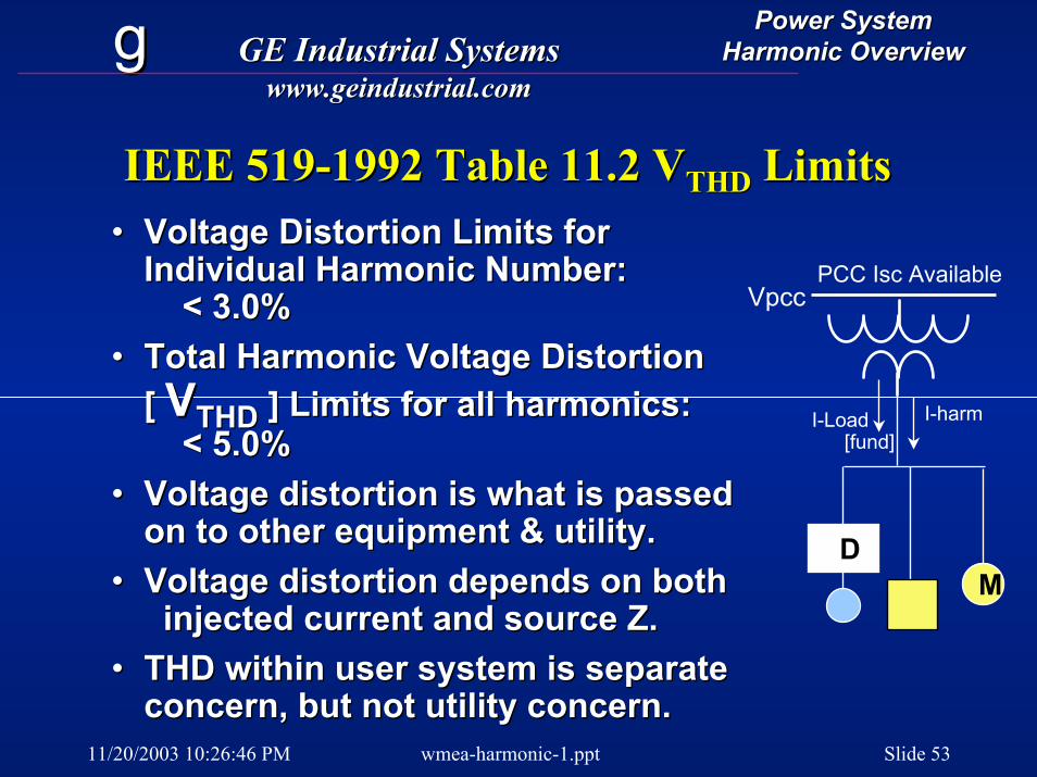
IEEE 519IEEE 519--1992 Table 11.2 V1992 Table 11.2 VTHDTHD LimitsLimits•• Voltage Distortion Limits forVoltage Distortion Limits for
Individual Harmonic Number:Individual Harmonic Number:< 3.0%< 3.0%
•• Total Harmonic Voltage DistortionTotal Harmonic Voltage Distortion[ [ VVTHDTHD ] Limits for all harmonics:] Limits for all harmonics:
< 5.0%< 5.0%•• Voltage distortion is what is passedVoltage distortion is what is passed
on to other equipment & utility.on to other equipment & utility.•• Voltage distortion depends on bothVoltage distortion depends on both
injected current and source Z. injected current and source Z. •• THD within user system is separateTHD within user system is separate
concern, but not utility concern.
I-Load[fund]
PCC Isc Available
I-harm
Vpcc
DM
concern, but not utility concern.
11/20/2003 10:26:46 PM wmea-harmonic-1.ppt Slide 54
gg GE Industrial SystemsGE Industrial Systemswww.geindustrial.comwww.geindustrial.com
Power SystemPower SystemHarmonic OverviewHarmonic Overview
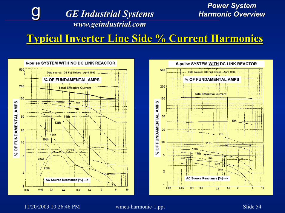
Typical Inverter Line Side % Current HarmonicsTypical Inverter Line Side % Current Harmonics
6-pulse SYSTEM WITH NO DC LINK REACTOR
% OF FUNDAMENTAL AMPS
500
200
100
50
20
10
2
5
1
Total Effective Current
5th
7th
11th
13th
17th19th
23rd
25th
% O
F FU
ND
AM
ENTA
L A
MPS
Data source: GE FujI Drives - April 1993
0.02 0.05 0.1 0.2 1.0 2 50.5 10
AC Source Reactance [%] --->
6-pulse SYSTEM WITH DC LINK REACTOR
% OF FUNDAMENTAL AMPS
500
200
100
50
20
2
5
1
Total Effective Current
5th
7th
11th
13th17th
19th
23rd
25th
% O
F FU
ND
AM
ENTA
L A
MPS
10
AC Source Reactance [%] --->
0.02
Data source: GE Fuji Drives - April 1993
0.05 0.1 0.2 1.0 2 50.5 10
11/20/2003 10:26:46 PM wmea-harmonic-1.ppt Slide 55
gg GE Industrial SystemsGE Industrial Systemswww.geindustrial.comwww.geindustrial.com
Power SystemPower SystemHarmonic OverviewHarmonic Overview
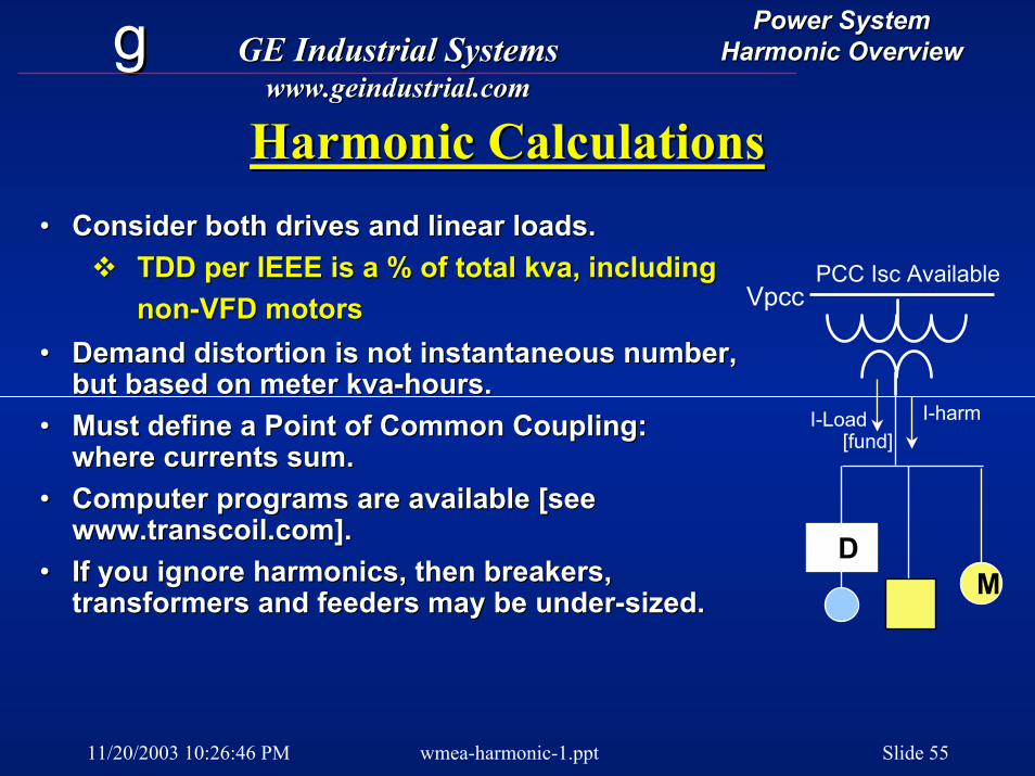
Harmonic CalculationsHarmonic Calculations•• Consider both drives and linear loads.Consider both drives and linear loads.
TDD per IEEE is a % of totalTDD per IEEE is a % of total kvakva, including , including nonnon--VFD motorsVFD motors
•• Demand distortion is not instantaneous number, Demand distortion is not instantaneous number, but based on meterbut based on meter kvakva--hours.hours.
•• Must define a Point of Common Coupling: Must define a Point of Common Coupling: where currents sum.where currents sum.
•• Computer programs are available [see Computer programs are available [see www.transcoil.com].www.transcoil.com].
•• If you ignore harmonics, then breakers, If you ignore harmonics, then breakers, transformers and feeders may be undertransformers and feeders may be under--sized.sized.
I-Load[fund]
PCC Isc Available
I-harm
Vpcc
DM
11/20/2003 10:26:46 PM wmea-harmonic-1.ppt Slide 56
gg GE Industrial SystemsGE Industrial Systemswww.geindustrial.comwww.geindustrial.com
Power SystemPower SystemHarmonic OverviewHarmonic Overview
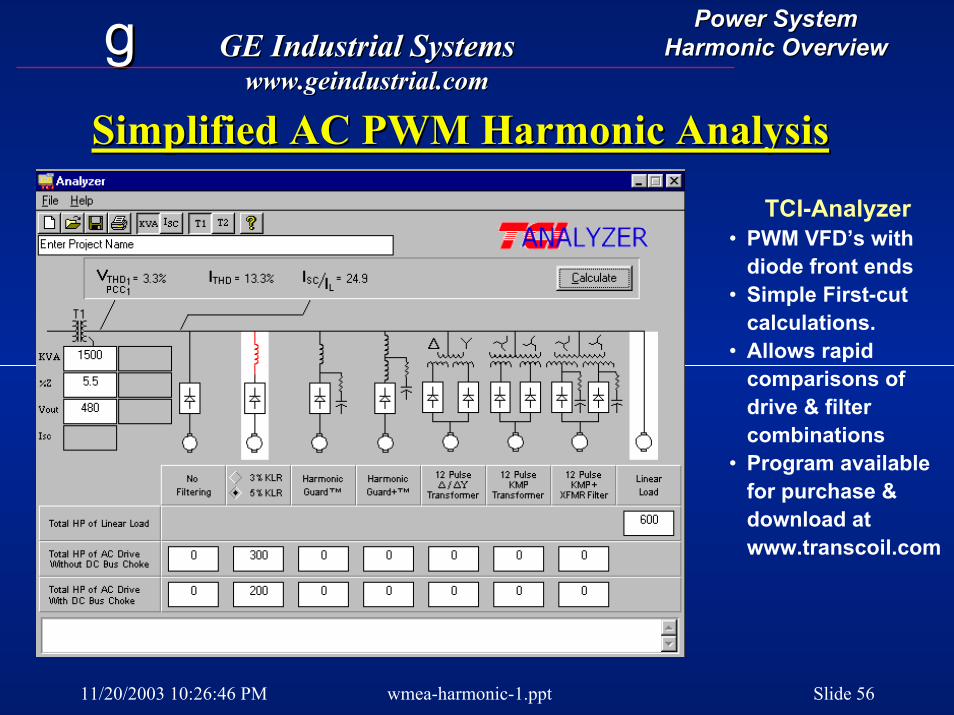
Simplified AC PWM Harmonic AnalysisSimplified AC PWM Harmonic Analysis
TCI-Analyzer• PWM VFD’s with
diode front ends• Simple First-cut
calculations.• Allows rapid
comparisons of drive & filter combinations
• Program available for purchase & download at www.transcoil.com
11/20/2003 10:26:46 PM wmea-harmonic-1.ppt Slide 57
gg GE Industrial SystemsGE Industrial Systemswww.geindustrial.comwww.geindustrial.com
Power SystemPower SystemHarmonic OverviewHarmonic Overview
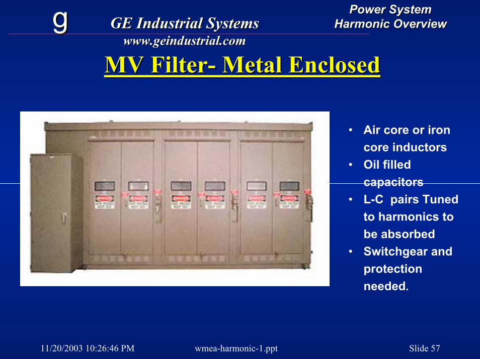
MV FilterMV Filter-- Metal EnclosedMetal Enclosed
• Air core or iron core inductors
• Oil filled capacitors
• L-C pairs Tuned to harmonics to be absorbed
• Switchgear and protection needed.
11/20/2003 10:26:46 PM wmea-harmonic-1.ppt Slide 58
gg GE Industrial SystemsGE Industrial Systemswww.geindustrial.comwww.geindustrial.com
Power SystemPower SystemHarmonic OverviewHarmonic Overview
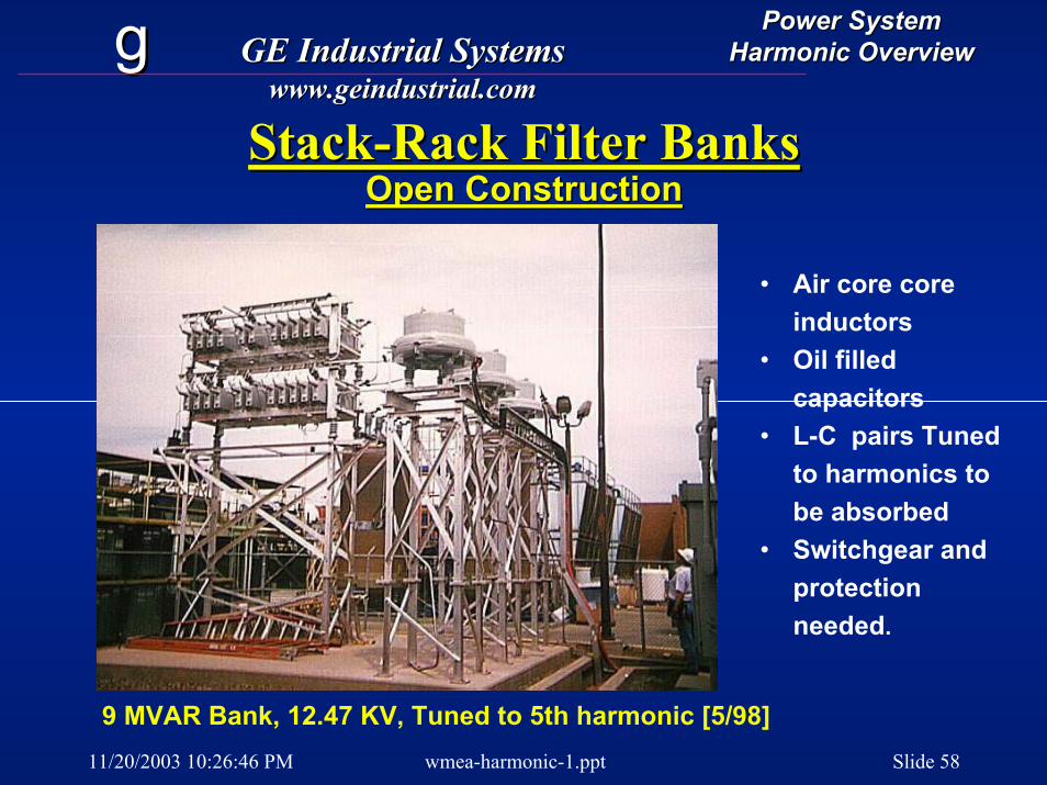
StackStack--Rack Filter Banks Rack Filter Banks Open ConstructionOpen Construction
• Air core core inductors
• Oil filled capacitors
• L-C pairs Tuned to harmonics to be absorbed
• Switchgear and protection needed.
9 MVAR Bank, 12.47 KV, Tuned to 5th harmonic [5/98]
11/20/2003 10:26:46 PM wmea-harmonic-1.ppt Slide 59
gg GE Industrial SystemsGE Industrial Systemswww.geindustrial.comwww.geindustrial.com
Power SystemPower SystemHarmonic OverviewHarmonic Overview
Typical Costs for MV Harmonic BanksTypical Costs for MV Harmonic Banks
•• Fixed = $30 / KVAR, Auto = $35Fixed = $30 / KVAR, Auto = $35--60 / KVAR60 / KVAR•• Not including:Not including:
Taps for iron core reactors (typically 35% adder to cost & sizeTaps for iron core reactors (typically 35% adder to cost & size))BreakersBreakersDisconnect switches, fused or unfusedDisconnect switches, fused or unfusedVacuum switchesVacuum switchesThermal protection for reactors (CT's & relays)Thermal protection for reactors (CT's & relays)Unbalance/Blown Fuse detection (CT's & relays)Unbalance/Blown Fuse detection (CT's & relays)Automatic banks (controllers, switches & reactors for each step)Automatic banks (controllers, switches & reactors for each step)Ground switchesGround switchesVentilation/heaters Ventilation/heaters Provisions for Kirk key interlocksProvisions for Kirk key interlocks
11/20/2003 10:26:46 PM wmea-harmonic-1.ppt Slide 60
gg GE Industrial SystemsGE Industrial Systemswww.geindustrial.comwww.geindustrial.com
Power SystemPower SystemHarmonic OverviewHarmonic Overview
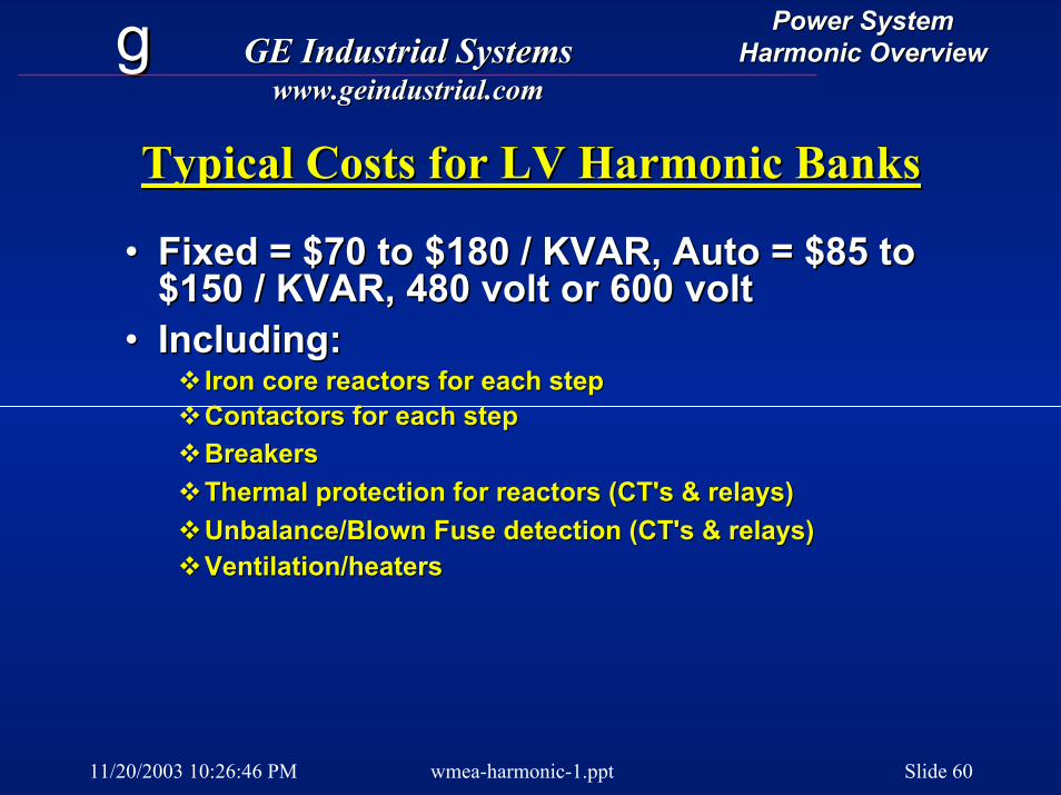
Typical Costs for LV Harmonic BanksTypical Costs for LV Harmonic Banks
•• Fixed = $70 to $180 / KVAR, Auto = $85 to Fixed = $70 to $180 / KVAR, Auto = $85 to $150 / KVAR, 480 volt or 600 volt$150 / KVAR, 480 volt or 600 volt
•• Including:Including:Iron core reactors for each step Iron core reactors for each step Contactors for each stepContactors for each stepBreakersBreakersThermal protection for reactors (CT's & relays)Thermal protection for reactors (CT's & relays)Unbalance/Blown Fuse detection (CT's & relays)Unbalance/Blown Fuse detection (CT's & relays)Ventilation/heatersVentilation/heaters
11/20/2003 10:26:46 PM wmea-harmonic-1.ppt Slide 61
gg GE Industrial SystemsGE Industrial Systemswww.geindustrial.comwww.geindustrial.com
Power SystemPower SystemHarmonic OverviewHarmonic Overview
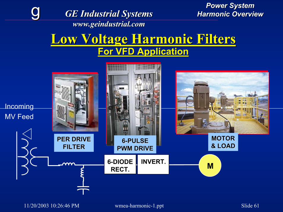
Low Voltage Harmonic Filters Low Voltage Harmonic Filters For VFD ApplicationFor VFD Application
MOTORMOTOR& LOAD& LOAD
66--PULSEPULSEPWM DRIVEPWM DRIVE
IncomingMV Feed
PER DRIVEPER DRIVEFILTERFILTER
INVERT.INVERT. M66--DIODEDIODERECT.RECT.

11/20/2003 10:26:46 PM wmea-harmonic-1.ppt Slide 62
gg GE Industrial SystemsGE Industrial Systemswww.geindustrial.comwww.geindustrial.com
Power SystemPower SystemHarmonic OverviewHarmonic Overview
Harmonic Correction:Harmonic Correction:Rational ApproachesRational Approaches
•• Correct known problems, use Correct known problems, use consultation if needed.consultation if needed.
•• Local filters Local filters -- at the source.at the source.•• System level filters.System level filters.•• Minimize injection of currents by Minimize injection of currents by
equipment selection & application.equipment selection & application.•• Maintain standards to prevent future Maintain standards to prevent future
problems.problems.
11/20/2003 10:26:46 PM wmea-harmonic-1.ppt Slide 63
gg GE Industrial SystemsGE Industrial Systemswww.geindustrial.comwww.geindustrial.com
Power SystemPower SystemHarmonic OverviewHarmonic Overview
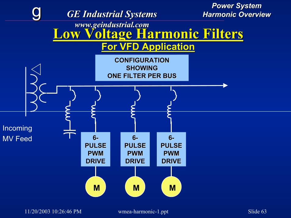
Low Voltage Harmonic Filters Low Voltage Harmonic Filters For VFD ApplicationFor VFD Application
CONFIGURATION CONFIGURATION SHOWINGSHOWING
ONE FILTER PER BUSONE FILTER PER BUS
IncomingMV Feed
M
66--PULSEPULSEPWM PWM
DRIVEDRIVE
M
66--PULSEPULSEPWM PWM
DRIVEDRIVE
M
66--PULSEPULSEPWM PWM
DRIVEDRIVE
M
66--PULSEPULSEPWM PWM
DRIVEDRIVE
11/20/2003 10:26:46 PM wmea-harmonic-1.ppt Slide 64
gg GE Industrial SystemsGE Industrial Systemswww.geindustrial.comwww.geindustrial.com
Power SystemPower SystemHarmonic OverviewHarmonic Overview
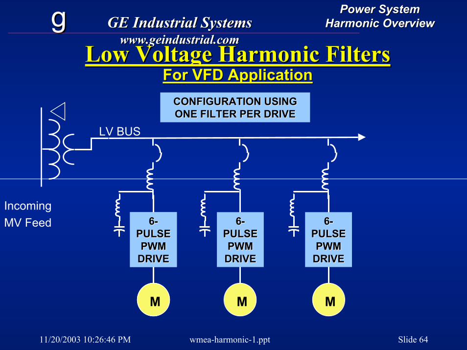
Low Voltage Harmonic Filters Low Voltage Harmonic Filters For VFD ApplicationFor VFD Application
IncomingMV Feed
M
66--PULSEPULSEPWM PWM
DRIVEDRIVE
M
66--PULSEPULSEPWM PWM
DRIVEDRIVE
LV BUS
CONFIGURATION USINGCONFIGURATION USINGONE FILTER PER DRIVEONE FILTER PER DRIVE
M
66--PULSEPULSEPWM PWM
DRIVEDRIVE
M
66--PULSEPULSEPWM PWM
DRIVEDRIVE
11/20/2003 10:26:46 PM wmea-harmonic-1.ppt Slide 65
gg GE Industrial SystemsGE Industrial Systemswww.geindustrial.comwww.geindustrial.com
Power SystemPower SystemHarmonic OverviewHarmonic Overview
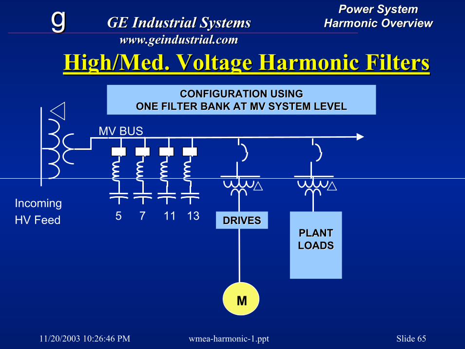
High/Med. Voltage Harmonic Filters High/Med. Voltage Harmonic Filters
IncomingHV Feed
MV BUS
5 7
CONFIGURATION USINGCONFIGURATION USINGONE FILTER BANK AT MV SYSTEM LEVELONE FILTER BANK AT MV SYSTEM LEVEL
11 13
M
DRIVESDRIVESPLANTPLANTLOADSLOADS
11/20/2003 10:26:46 PM wmea-harmonic-1.ppt Slide 66
gg GE Industrial SystemsGE Industrial Systemswww.geindustrial.comwww.geindustrial.com
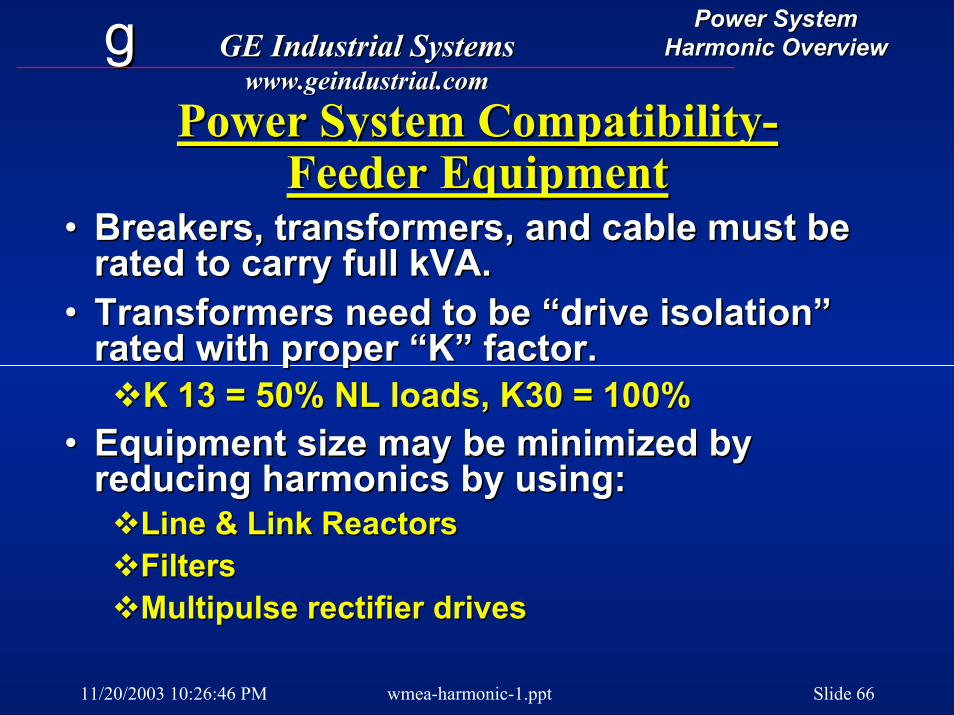
Power SystemPower SystemHarmonic OverviewHarmonic Overview
Power System CompatibilityPower System Compatibility--Feeder EquipmentFeeder Equipment
•• Breakers, transformers, and cable must be Breakers, transformers, and cable must be rated to carry fullrated to carry full kVAkVA..
•• Transformers need to be “drive isolation” Transformers need to be “drive isolation” rated with proper “K” factor.rated with proper “K” factor.
K 13 = 50% NL loads, K30 = 100%K 13 = 50% NL loads, K30 = 100%•• Equipment size may be minimized by Equipment size may be minimized by
reducing harmonics by using:reducing harmonics by using:Line & Link ReactorsLine & Link ReactorsFiltersFiltersMultipulse rectifier drivesMultipulse rectifier drives
11/20/2003 10:26:46 PM wmea-harmonic-1.ppt Slide 67
gg GE Industrial SystemsGE Industrial Systemswww.geindustrial.comwww.geindustrial.com
Power SystemPower SystemHarmonic OverviewHarmonic Overview
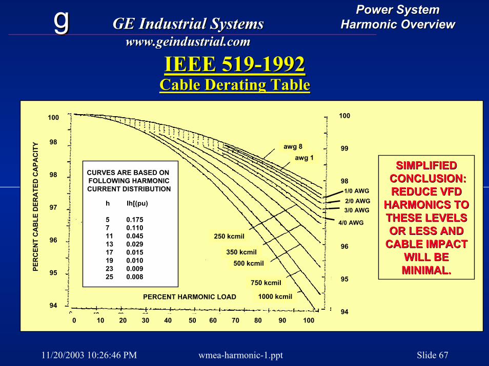
IEEE 519IEEE 519--19921992Cable Derating TableCable Derating Table
100
99
98
97
96
95
94
CURVES ARE BASED ONFOLLOWING HARMONICCURRENT DISTRIBUTION
h Ih[(pu)
5 0.1757 0.11011 0.04513 0.02917 0.01519 0.01023 0.00925 0.008
0 10 20 30 40 50 60 70 80 90 100
100
98
98
97
96
95
94PERCENT HARMONIC LOAD
PER
CEN
T C
AB
LE D
ERA
TED
CA
PAC
ITY
1/0 AWG2/0 AWG3/0 AWG
4/0 AWG
250 kcmil
350 kcmil500 kcmil
750 kcmil
1000 kcmil
awg 8awg 1
SIMPLIFIEDSIMPLIFIEDCONCLUSION:CONCLUSION:REDUCE VFDREDUCE VFD
HARMONICS TOHARMONICS TOTHESE LEVELSTHESE LEVELSOR LESS ANDOR LESS AND
CABLE IMPACTCABLE IMPACTWILL BEWILL BEMINIMAL.MINIMAL.
11/20/2003 10:26:46 PM wmea-harmonic-1.ppt Slide 68
gg GE Industrial SystemsGE Industrial Systemswww.geindustrial.comwww.geindustrial.com
Power SystemPower SystemHarmonic OverviewHarmonic Overview
Harmonic SolutionsHarmonic Solutions
•Understanding•Planning•Studies & surveys•Filters•Low impact equip
11/20/2003 10:26:46 PM wmea-harmonic-1.ppt Slide 69
gg GE Industrial SystemsGE Industrial Systemswww.geindustrial.comwww.geindustrial.com
Power SystemPower SystemHarmonic OverviewHarmonic Overview
Harmonic SurveysHarmonic Surveys
•• What are they?What are they?•• When are they needed?When are they needed?
Serious & widespread symptomsSerious & widespread symptomsStarting freshStarting freshTo fix utility complaintsTo fix utility complaints
•• Localized or system wide?Localized or system wide?
11/20/2003 10:26:46 PM wmea-harmonic-1.ppt Slide 70
gg GE Industrial SystemsGE Industrial Systemswww.geindustrial.comwww.geindustrial.com
Power SystemPower SystemHarmonic OverviewHarmonic Overview
Harmonic SurveysHarmonic Surveys
•• DoDo--itit--yourself Approachyourself ApproachMeasurement locationsMeasurement locationsInstrument availability, setup, Instrument availability, setup, calibration.calibration.Data interpretationData interpretation
•• When do you need professional When do you need professional help?help?
11/20/2003 10:26:46 PM wmea-harmonic-1.ppt Slide 71
gg GE Industrial SystemsGE Industrial Systemswww.geindustrial.comwww.geindustrial.com
Power SystemPower SystemHarmonic OverviewHarmonic Overview
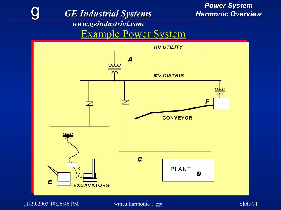
Example Power SystemExample Power System
PLANT
CONVEYOR
HV UTILITY
MV DISTRIB
EXCAVATORSE
C
D
F
A
11/20/2003 10:26:46 PM wmea-harmonic-1.ppt Slide 72
gg GE Industrial SystemsGE Industrial Systemswww.geindustrial.comwww.geindustrial.com
Power SystemPower SystemHarmonic OverviewHarmonic Overview
Using Harmonic Survey ResultsUsing Harmonic Survey Results
•• Recognize what data means trouble, Recognize what data means trouble, and what can be ignored. and what can be ignored.
•• Know the industry standards.Know the industry standards.•• Know how to apply standards with Know how to apply standards with
practical results in sight at lowest practical results in sight at lowest cost.cost.
11/20/2003 10:26:46 PM wmea-harmonic-1.ppt Slide 73
gg GE Industrial SystemsGE Industrial Systemswww.geindustrial.comwww.geindustrial.com
Power SystemPower SystemHarmonic OverviewHarmonic Overview
SummarySummary
•• Use common sense approach Use common sense approach -- don’t don’t be pushed into excessive action.be pushed into excessive action.
•• Recognize symptoms of harmonic Recognize symptoms of harmonic problems.problems.
•• Use design tools to do simple calcs Use design tools to do simple calcs and planningand planning
•• Consult reliable systems analysis Consult reliable systems analysis sources when help is needed.sources when help is needed.

11/20/2003 10:26:46 PM wmea-harmonic-1.ppt Slide 74
gg GE Industrial SystemsGE Industrial Systemswww.geindustrial.comwww.geindustrial.com
Power SystemPower SystemHarmonic OverviewHarmonic Overview
SummarySummary
•• Use common sense approach Use common sense approach -- don’t don’t be pushed into excessive action.be pushed into excessive action.
•• Recognize symptoms of harmonic Recognize symptoms of harmonic problems.problems.
•• Use design tools to do simple calcs Use design tools to do simple calcs and planningand planning
•• Consult reliable systems analysis Consult reliable systems analysis sources when help is needed.sources when help is needed.