power quality improvement by using multi-pulse ac-dc ... · pdf fileavailable online at...
TRANSCRIPT

A
mdocF©
K
1
(1vaudfrt
2
Available online at www.sciencedirect.com
ScienceDirect
Journal of Electrical Systems and Information Technology 1 (2014) 255–265
Power quality improvement by using multi-pulse AC-DC convertersfor DC drives: Modeling, simulation and its digital implementation
Mohd Tariq a,∗,1, Md. Tauquir Iqbal b
a Department of Electrical Engineering, Maulana Azad National Institute of Technology, Bhopal, Indiab Damodar Valley Corporation, Kolkata, India
Available online 19 December 2014
bstract
The paper presents the modeling, simulation and digital implementation of power quality improvement of DC drives by usingulti pulse AC–DC converter. As it is a well-known fact that power quality determines the fitness of electrical power to consumer
evices, hence an effort has been made to improve power quality in this work. Simulation and digital implementation with the helpf MATLAB/Simulink has been done and results obtained are discussed in detail to verify the theoretical results. The multipulseonverter was connected with DC drives and was run at no load condition to find out the transient and steady state performances.FT analysis has been performed and Total Harmonic Distortion (THD) results obtained at different pulses are shown here.
2015 Electronics Research Institute (ERI). Production and hosting by Elsevier B.V. All rights reserved.
eywords: Multi pulse converter; DC motor; DC drives; AC/DC converter; THD; MATLAB/Simulink
. Introduction
Nowadays, the use of solid-state converters in various applications, such as DC drives, variable frequency drivesVFD), heating and lighting industries, shipping (transportation) industry, electric vehicle etc. has vastly grown (Bose,992). Semiconductor switching devices which are generally used in converter circuits generates significant harmonicoltages/currents. The diode bridge rectifiers are considered as a major contributor to the power system harmonicsnd the consequences are varying from electrical components overheating (like winding heating leading to fail-re/breakdown of machine) to communication interference in communication lines (Wakileh, 2001). The DC motorrive is used in many industries in order to convert electrical energy into mechanical energy. One of the main reasons
or choosing DC motors over their AC counterparts is due to the simplicity of their speed control (Dubey, 2002). Theeliability and quality of power supplies relates closely to the economic advancement/growth of a country. The mainask of the utility system is to provide the power to consumer/industry load with proper sinusoidal wave of the voltage∗ Corresponding author. Tel.: +91 9045635995.E-mail address: [email protected] (M. Tariq).
1 Presently at School of Electrical and Electronics Engineering, Nanyang Technological University, Singapore.Peer review under responsibility of Electronics Research Institute (ERI).
http://dx.doi.org/10.1016/j.jesit.2014.12.007314-7172/© 2015 Electronics Research Institute (ERI). Production and hosting by Elsevier B.V. All rights reserved.

256 M. Tariq, Md.T. Iqbal / Journal of Electrical Systems and Information Technology 1 (2014) 255–265
and current, with fixed frequency (50 Hz in case of India and 60 Hz in case of USA) and magnitude with minimizedTHD as possible, according to IEEE 519-1992 standard (THD should be less than 5%) (IEEE, 1993). The typical powersystem contains many non-linear loads like electric arc furnaces, power electronic converters etc. which introducescurrent and voltage harmonics. In view of the above problem, the reduction of harmonics in switching converters usingmulti pulse converter is considered in this paper.
In literature, several papers are found on reducing THD of the power systems which are detailed below in Section2, but a comprehensive approach is missing in the literature hence an effort has been made to present it here.
In this paper, modeling, simulation and digital implementation of power quality improvement by using multi-pulseAC-DC converters for DC drives has been presented section wise. Section 2 gives the detail regarding available workin literature on reducing THD. Section 3 presents modeling of 12 pulse uncontrolled and controlled converter, 24 pulsecontrolled converter. Section 4 presents digital implementation, THD results and discussion. Section 5 concludes thispaper.
2. Literature review
In literature, the focus of research is to eliminate harmonics in switching converters. Many methods are there, and theresearchers have used the methods according to the needs and suitability. Some of the methods with their applicationsare discussed here. The Selective harmonic elimination (SHE) PWM based methods can be applied for highest qualityof output among all the PWM methods as SHE offers several advantages with low switching frequency to fundamentalfrequency ratios, direct control over output waveform harmonics, and the ability to leave triple harmonics uncontrolledto take advantage of circuit topology in three phase system (Sahali and Fellah, 2003).
A multilevel AC/DC, DC/AC converter is used to determine the switching angles so that the converter produces therequired fundamental voltage and does not generate specific lower order dominant harmonics. A unified approach is
presented in the literature to solve the harmonic elimination equations for all of the various switching schemes (Wanget al., 2005). There are various methods to mitigate voltage sags and swells, but the use of a custom power device isconsidered to be the most efficient method, such as FACTS for transmission systems which improve the power transfercapabilities and stability margins (Qiang Song et al., 2004). Modeling of multi pulse converter is also discussed in detailFig. 1. Uncontrolled 12 pulse Model in MATLAB/Simulink.

M. Tariq, Md.T. Iqbal / Journal of Electrical Systems and Information Technology 1 (2014) 255–265 257
Fig. 2. Controlled 12 pulse Model in MATLAB/Simulink.
Fig. 3. Controlled 24 pulse Model in MATLAB/Simulink.

258 M. Tariq, Md.T. Iqbal / Journal of Electrical Systems and Information Technology 1 (2014) 255–265
Fig. 4. Control block diagram.
Fig. 5. Vab (Line Voltage) and its THD = 22.31%, for 12 pulse uncontrolled rectifier.
in literature. Adjustable speed DC drives consists of a rectifier section. The AC source voltage is converted into a DCvoltage by the rectifier circuit, and then the DC voltage is fed to the adjustable speed DC motor. The six-diode bridgerectifier is most widely used as an AC-to-DC converter. This diode rectifier has a nonlinear (i.e. non-sinusoidal) loadcharacteristic causing harmonic currents flow into the power source which results in line voltage distortion. GenerallyDiode bridges are used with a higher number of pulses for reducing harmonics in AC mains and reduced value of
ripple voltage in the DC output. These are developed in 6, 12, 18, 24, 30, 36, 48 pulses etc., converters through inputmulti pulse auto/isolation transformers and ripple current injection employing interphase reactors (Singh et al., 2008;Chivite-Zabalza and Forsyth, 2007; Singh et al., 2007).
M. Tariq, Md.T. Iqbal / Journal of Electrical Systems and Information Technology 1 (2014) 255–265 259
Fig. 6. Speed response of DC motor, at 88% rated speed.
Fig. 7. Voltage across DC input (armature terminal of DC Motor), Ripple = 195–65 = 130 V.
Fig. 8. Output DC Current ripple (2.7–1.2 = 1.50 A).
260 M. Tariq, Md.T. Iqbal / Journal of Electrical Systems and Information Technology 1 (2014) 255–265
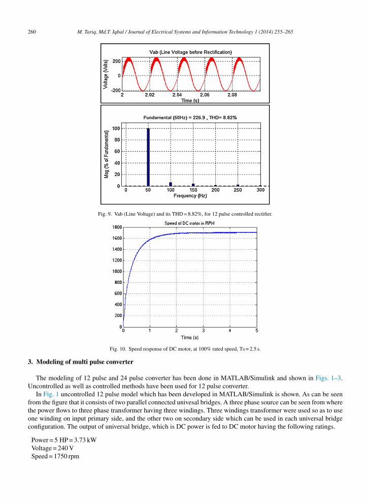
Fig. 9. Vab (Line Voltage) and its THD = 8.82%, for 12 pulse controlled rectifier.
Fig. 10. Speed response of DC motor, at 100% rated speed, Ts = 2.5 s.
3. Modeling of multi pulse converter
The modeling of 12 pulse and 24 pulse converter has been done in MATLAB/Simulink and shown in Figs. 1–3.Uncontrolled as well as controlled methods have been used for 12 pulse converter.
In Fig. 1 uncontrolled 12 pulse model which has been developed in MATLAB/Simulink is shown. As can be seenfrom the figure that it consists of two parallel connected univesal bridges. A three phase source can be seen from wherethe power flows to three phase transformer having three windings. Three windings transformer were used so as to useone winding on input primary side, and the other two on secondary side which can be used in each universal bridgeconfiguration. The output of universal bridge, which is DC power is fed to DC motor having the following ratings.
Power = 5 HP = 3.73 kWVoltage = 240 VSpeed = 1750 rpm
M. Tariq, Md.T. Iqbal / Journal of Electrical Systems and Information Technology 1 (2014) 255–265 261
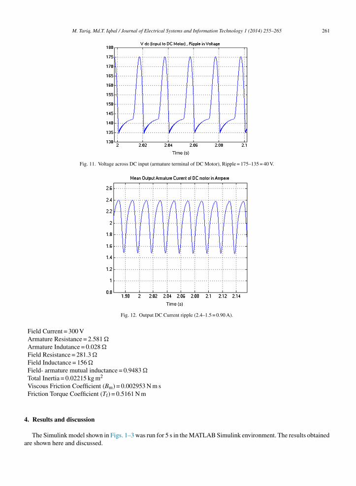
Fig. 11. Voltage across DC input (armature terminal of DC Motor), Ripple = 175–135 = 40 V.
4
a
Fig. 12. Output DC Current ripple (2.4–1.5 = 0.90 A).
Field Current = 300 VArmature Resistance = 2.581 �
Armature Indutance = 0.028 �
Field Resistance = 281.3 �
Field Inductance = 156 �
Field- armature mutual inductance = 0.9483 �
Total Inertia = 0.02215 kg m2
Viscous Friction Coefficient (Bm) = 0.002953 N m sFriction Torque Coefficient (Tf) = 0.5161 N m
. Results and discussion
The Simulink model shown in Figs. 1–3 was run for 5 s in the MATLAB Simulink environment. The results obtainedre shown here and discussed.
262 M. Tariq, Md.T. Iqbal / Journal of Electrical Systems and Information Technology 1 (2014) 255–265
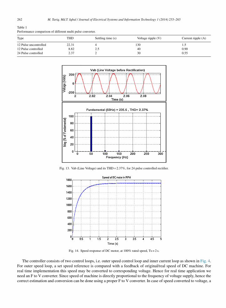
Table 1Performance comparison of different multi pulse converter.
Type THD Settling time (s) Voltage ripple (V) Current ripple (A)
12 Pulse uncontrolled 22.31 4 130 1.512 Pulse controlled 8.82 2.5 40 0.9024 Pulse controlled 2.37 2 30 0.55
Fig. 13. Vab (Line Voltage) and its THD = 2.37%, for 24 pulse controlled rectifier.
Fig. 14. Speed response of DC motor, at 100% rated speed, Ts = 2 s.
The controller consists of two control loops, i.e. outer speed control loop and inner current loop as shown in Fig. 4.For outer speed loop, a set speed reference is compared with a feedback of original/real speed of DC machine. For
real time implementation this speed may be converted to corresponding voltage. Hence for real time application weneed an F to V converter. Since speed of machine is directly proportional to the frequency of voltage supply, hence thecorrect estimation and conversion can be done using a proper F to V converter. In case of speed converted to voltage, a
M. Tariq, Md.T. Iqbal / Journal of Electrical Systems and Information Technology 1 (2014) 255–265 263
Fig. 15. Voltage across DC input (armature terminal of DC Motor), Ripple = 177–147 = 30 V.
vakt
l
poui
v
Fig. 16. Output DC Current ripple (2.3–1.75 = 0.55 A).
oltage reference has to be given. The error generated by comparing the set speed and real speed is then passed through PI controller to generate a reference current. This will act as a reference for inner current loop, which is necessaryeeping in view the current limit of electrical machines and switch. The error is again passed through a PI controllero generate switching signals which in turn generate switching pulses for IGBT switches.
Figs. 5–8 show the results when 12 pulses uncontrolled rectifier was used. Fig. 5 shows the input AC voltage (Vabine voltage before rectification with THD = 22.31%). THD is calculated by doing FFT analysis.
Fig. 6 shows speed response of DC motor when fed with DC power obtained after rectification with the help of 12ulse uncontrolled rectifier. As seen from the figure the motor is operated at 88% rated speed (1500). It is uncontrolledperation hence no speed reference and control reference was given. The settling time is nearly 4 s. Hence for anncontrolled system, settling time is very high with speed just going up to 88% approximately of the rated speednstead of 100%.
Figs. 7 and 8 shows voltage and current ripple on the DC side. The voltage ripple is shown to be 130 V, which is aery big quantity. The current ripple is also 1.5 A which is again a very big number.

264 M. Tariq, Md.T. Iqbal / Journal of Electrical Systems and Information Technology 1 (2014) 255–265
Fig. 17. Graphical representation of performance comparison of different multi pulse converter.
Hence to improve the THD, speed response, output ripple in voltage and current the same 12 pulse converter hasbeen operated with a close loop control. In Fig. 2, diode bridge is replaced by thyristors and firing angle is controlledby the error generated between the set reference speed of 1700 rpm speed and actual speed. The error signal is passedthrough a PI controller before passing through a logic signal to generate switching pulses for thyristors.
Figs. 9–12 show the results when 12 pulses controlled rectifier was used. Fig. 9 shows the input AC voltage (Vabline voltage before rectification with THD = 8.82%). Here also the THD is calculated by doing FFT analysis.
Fig. 10 shows speed response of DC motor when fed with DC power obtained after rectification with the help of 12pulse controlled rectifier. The reference speed here is 1700 rpm. As seen from the figure the motor can now be operatedat 100% rated speed. It is controlled operation hence is operating at 100% rated speed. The settling time is nearly 2.5 s.Hence for a controlled system, settling time has been reduced as well as the steady state error also.
Figs. 11 and 12 show voltage and current ripple on the DC side has decreased considerably after using controloperation. The voltage ripple is shown to be 40 V, which is very less as compared to 130 V in the previous case. Thecurrent ripple in control operation is shown 0.90 A which is again very less in comparison to 1.5 A for uncontrolledoperation.
Figs. 13–16 show the results when 24 pulses controlled rectifier was used. Fig. 13 shows the input AC voltage (Vabline voltage before rectification with THD = 2.37%). Here also the THD is calculated by doing FFT analysis.
Fig. 14 shows speed response of DC motor when fed with DC power obtained after rectification with the help of 24pulse controlled rectifier. The reference speed here is 1700 rpm. As seen from the figure, here again the motor is beingoperated at 100% rated speed. It is controlled operation hence is operating at 100% rated speed. The settling time isnearly 2 s. Hence for a controlled 24 pulse converter system, settling time has been further reduced.
Figs. 15 and 16 show voltage and current ripple on the DC side has decreased considerably after using controloperation for 24 pulses. The voltage ripple is shown to be 30 V, which is less as compared to 40 V in previous case. Thecurrent ripple in controlled 24 pulse converter operation is shown 0.55 A which is again less in comparison to 0.9 Afor controlled 12 pulse operation. Table 1 has been shown here, from where we can better understand the performanceimprovement for different multi pulse converter explored in this paper (Fig. 17).
5. Conclusion
In this paper a performance comparison of multi pulse converter has been carried out. 12 pulse uncontrolled, 12pulse controlled and 24 pulse controlled AC/DC converters has been modeled and simulated in MATLAB/Simulink.

Ttbh
A
To
R
BC
DIQ
S
S
S
WW
M. Tariq, Md.T. Iqbal / Journal of Electrical Systems and Information Technology 1 (2014) 255–265 265
he results obtained are analyzed and it is proved that as we increase the no. of pulses THD decreases, settlingime decreases, Output Voltage and current ripple also decreases considerably. Moreover a comparison has been doneetween an uncontrolled AC/DC converter and a controlled AC/DC converter and it was found out that control operationas better performance i.e. less steady state error and less settling time although the stability of the system decreases.
cknowledgements
The authors are grateful to the Head, Department of Electrical Engineering, Maulana Azad National Institute ofechnology, Bhopal, India for providing all facilities for completion of this work. The work was done in the laboratoryf Electrical Engineering Department, MANIT.
eferences
ose, B.K., January 1992. Recent advances in power electronics. Power Electronics, IEEE Transactions on, 2–16.hivite-Zabalza, F.J., Forsyth, A.J., May 2007. A Passive 36-Pulse AC–DC converter with inherent load balancing using combined harmonic voltage
and current injection. Power Electronics, IEEE Transactions on 22 (3), 1027–1035.ubey, G.K., May 2002. Fundamentals of Electrical Drives. CRC Press.
EEE Recommended Practices and Requirements for Harmonic Control in Electrical Power Systems, April 9 1993, IEEE Std 519–1992, pp. 1–112.iang Song, Wenhua Liu, Zhichang Yuan, Wenhui Wei, Yuanhua Chen, 2004. DC voltage balancing technique using multi-pulse optimal PWM for
cascade H-bridge inverters based STATCOM. Power Electronics Specialists Conference, PESC 04. IEEE 35th Annual, vol. 6, pp. 4768–4772.ahali, Y., Fellah, M.K., June 2003. Selective harmonic eliminated pluse-width modulation technique (SHE PWM) applied to three-level
inverter/converter, Industrial Electronics. ISIE’03. IEEE International Symposium on Industrial Electronics 2, 1112–1117.ingh, B., Gairola, S., Chandra, A., Kamal Al-Haddad, June 2007. Zigzag connected autotransformer based controlled AC-DC converter for pulse
multiplication. IEEE International Symposium on Industrial Electronics (ISIE), 889–894, 4–7.ingh, B., Gairola, S., Singh, B.N., Chandra, A., Al-Haddad, K., January 2008. Multipulse AC–DC converters for improving power quality: a review.
Power Electronics, IEEE Transactions on 23 (1), 260–281.akileh, G.J., 2001. Power Systems Harmonics, Fundamentals, Analysis and Filter Design. Springer.ang, J., Huang, Y., Peng, F.Z., 2005. A practical harmonics elimination method for multilevel inverters. In: Industry Applications Conference.
Fourtieth IAS Annual Meeting. Conference Record of the 2005, Volume: 3, 2–6 October, pp. 1665–1670.