power quality aspects of electric traction sh. r.n lal sr. executive director/ti & sh. s....
TRANSCRIPT
Power Quality Aspects of
Electric Traction
Sh. R.N Lal Sr. Executive Director/TI
& Sh. S. Bhatnagar
Jt. Director/ TI RDSO/Luckow
Out Line of the presentation What is total power quality ? International power quality standards. Statutory requirements for IR. Power quality control techniques. Harmonics & voltage unbalance control. Scenario on IR. Internationally followed practices on total power quality system. Conclusion and recommendations.
Power Quality Definition
The term power quality is used to describe the extent of variation of the voltage, current and frequency on the power system. The variation of voltage and current can either be in terms of magnitude or waveform shape/distortion.
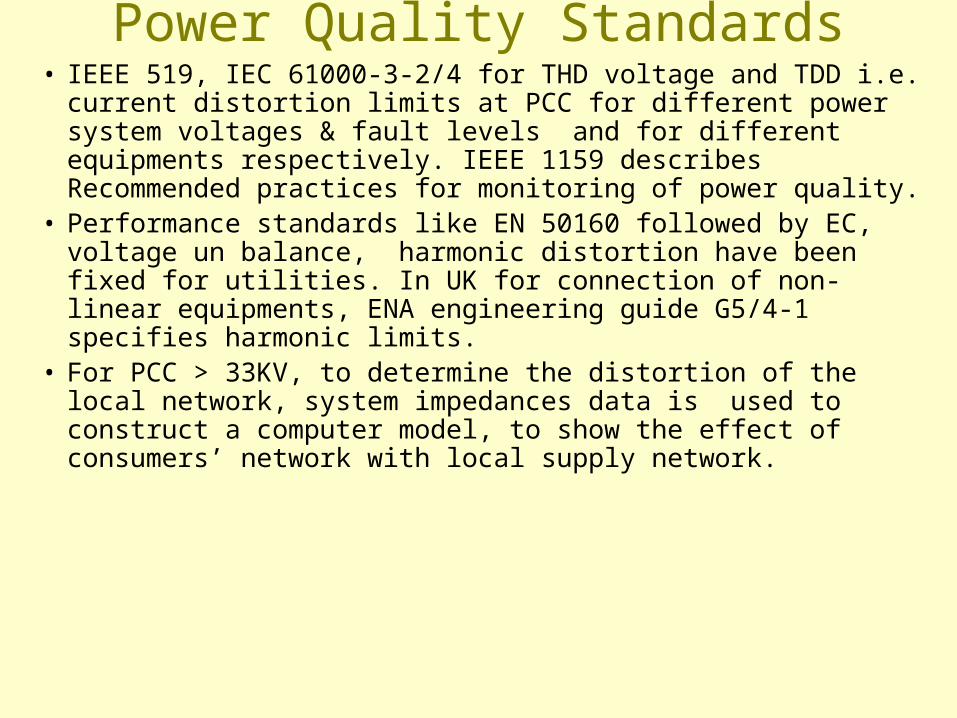
Power Quality Standards• IEEE 519, IEC 61000-3-2/4 for THD voltage and TDD i.e. current
distortion limits at PCC for different power system voltages & fault levels and for different equipments respectively. IEEE 1159 describes Recommended practices for monitoring of power quality.
• Performance standards like EN 50160 followed by EC, voltage un balance, harmonic distortion have been fixed for utilities. In UK for connection of non-linear equipments, ENA engineering guide G5/4-1 specifies harmonic limits.
• For PCC > 33KV, to determine the distortion of the local network, system impedances data is used to construct a computer model, to show the effect of consumers’ network with local supply network.
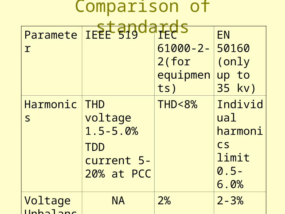
Comparison of standardsParameter IEEE 519 IEC 61000-
2-2(for equipments)
EN 50160 (only up to 35 kv)
Harmonics THD voltage 1.5-5.0%
TDD current 5-20% at PCC
THD<8% Individual harmonics limit 0.5-6.0%
Voltage Unbalance
NA 2% 2-3%
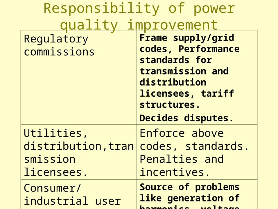
Responsibility of power quality improvement
Regulatory commissions Frame supply/grid codes, Performance standards for transmission and distribution licensees, tariff structures.
Decides disputes.
Utilities, distribution,transmission licensees.
Enforce above codes, standards. Penalties and incentives.
Consumer/industrial user Source of problems like generation of harmonics, voltage sags etc.Required to follow all rules and regulation.
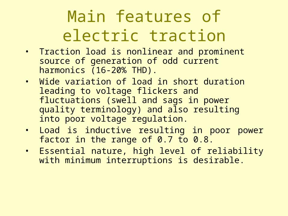
Main features of electric traction
• Traction load is nonlinear and prominent source of generation of odd current harmonics (16-20% THD).
• Wide variation of load in short duration leading to voltage flickers and fluctuations (swell and sags in power quality terminology) and also resulting into poor voltage regulation.
• Load is inductive resulting in poor power factor in the range of 0.7 to 0.8.
• Essential nature, high level of reliability with minimum interruptions is desirable.
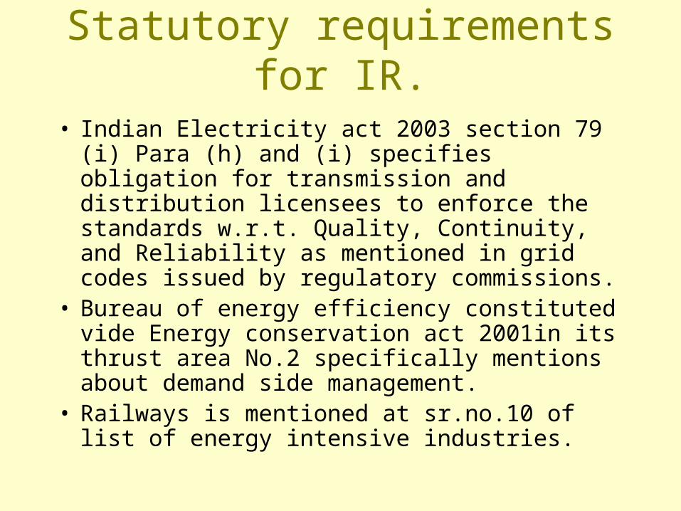
Statutory requirements for IR.
• Indian Electricity act 2003 section 79 (i) Para (h) and (i) specifies obligation for transmission and distribution licensees to enforce the standards w.r.t. Quality, Continuity, and Reliability as mentioned in grid codes issued by regulatory commissions.
• Bureau of energy efficiency constituted vide Energy conservation act 2001in its thrust area No.2 specifically mentions about demand side management.
• Railways is mentioned at sr.no.10 of list of energy intensive industries.
Aspects of Power Quality relevant to Indian Railways
1. Compensation of reactive power to improve power factor.
2. Compensation or elimination of harmonics in the system, for improvement in voltage form factor and reduction of line losses.
3. Correction of voltage imbalance in 3 phase supply system.
4. Correction of short duration voltage disturbances i.e. sag , swell and flickers.
Compensation of reactive power to improve
power factor Reactive power compensation Methods to improve PF• Using HT capacitors with 13% detuned reactors. It also act as passive
filters for filtering of harmonics. • Static VAR compensators (SVC) : It uses switching devices to control
capacitive or inductive energy into the system. Available SVC configurations are Thyristor switched capacitors (TSC), Thyristor controlled reactors with passive filters(TCR).
Self commutated VAR generators: The fast switching power electronic devices are used to act either as voltage or current fed inverter to inject required amount of leading/lagging reactive KVAR into the system.
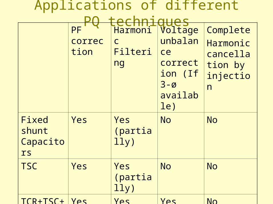
Applications of different PQ techniquesPF correction
Harmonic Filtering
Voltage unbalance correction (If 3-ø available)
Complete
Harmonic cancellation by injection
Fixed shunt Capacitors
Yes Yes (partially)
No No
TSC Yes Yes (partially)
No No
TCR+TSC+FILTERS
Yes Yes Yes No
VSC/STATCON
Yes Yes (with fixed Shunt capacitors)
Yes Yes
Effects of harmonics in the system
• Form factor deterioration, i.e. ratio between the RMS and the Average value of the rectified traction voltage. Increase of form factor means reduction in ability of loco to absorb power from system.
• Harmonics are also non useful reactive energy and cause poor PF.
• Increase in line current and losses.• Limitations of signaling track circuits.• Interference to telecommunication.• Limitations of harmonic injections into public utility.
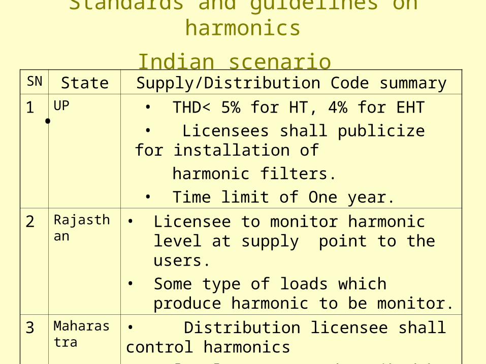
Standards and guidelines on harmonics
Indian scenario
•
SN State Supply/Distribution Code summary
1 UP • THD< 5% for HT, 4% for EHT
• Licensees shall publicize for installation of
harmonic filters.
• Time limit of One year.
2 Rajasthan • Licensee to monitor harmonic level at supply point to the users.
• Some type of loads which produce harmonic to be monitor.
3 Maharastra • Distribution licensee shall control harmonics
level at PCC as described by IEEE 519-1992
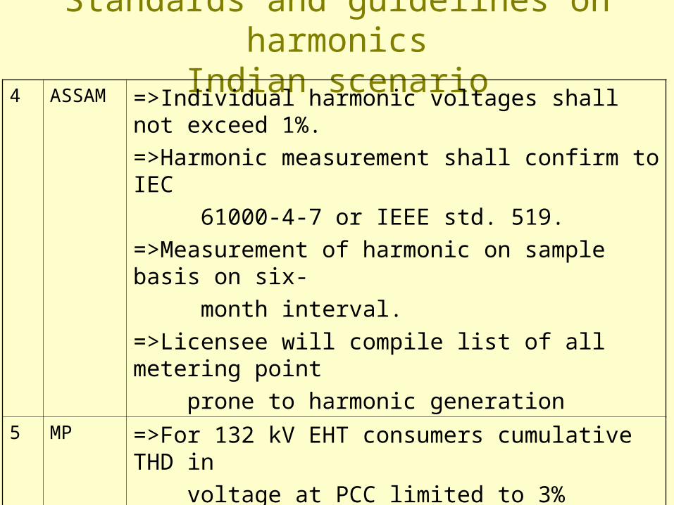
Standards and guidelines on harmonicsIndian scenario
4 ASSAM =>Individual harmonic voltages shall not exceed 1%.
=>Harmonic measurement shall confirm to IEC
61000-4-7 or IEEE std. 519.
=>Measurement of harmonic on sample basis on six-
month interval.
=>Licensee will compile list of all metering point
prone to harmonic generation 5 MP =>For 132 kV EHT consumers cumulative THD in
voltage at PCC limited to 3%
=>Licensee to monitor harmonic level at strategic point at
regular interval.
=>Licensee can measure the harmonics generation of any
customer.
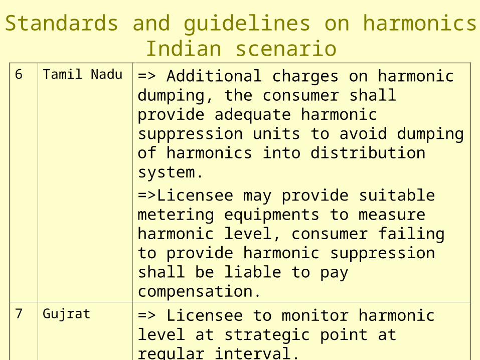
6 Tamil Nadu => Additional charges on harmonic dumping, the consumer shall provide adequate harmonic suppression units to avoid dumping of harmonics into distribution system.
=>Licensee may provide suitable metering equipments to measure harmonic level, consumer failing to provide harmonic suppression shall be liable to pay compensation.
7 Gujrat => Licensee to monitor harmonic level at strategic point at regular interval.
=>Licensee can measure the harmonics generation of any customer.
=>Licensee shall follow the harmonics distortion limits as laid down by grid connectivity standards
Standards and guidelines on harmonicsIndian scenario
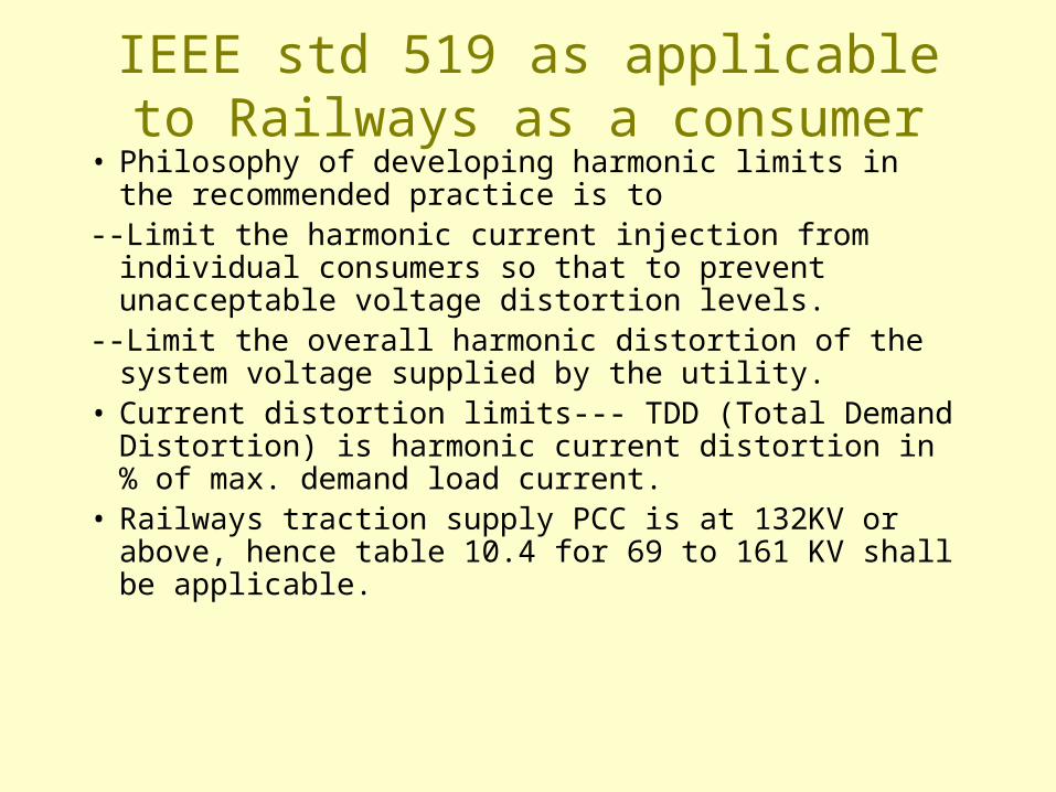
IEEE std 519 as applicable to Railways as a consumer
• Philosophy of developing harmonic limits in the recommended practice is to
--Limit the harmonic current injection from individual consumers so that to prevent unacceptable voltage distortion levels.
--Limit the overall harmonic distortion of the system voltage supplied by the utility.
• Current distortion limits--- TDD (Total Demand Distortion) is harmonic current distortion in % of max. demand load current.
• Railways traction supply PCC is at 132KV or above, hence table 10.4 for 69 to 161 KV shall be applicable.
IEEE std 519 as applicable to Railways as a consumer
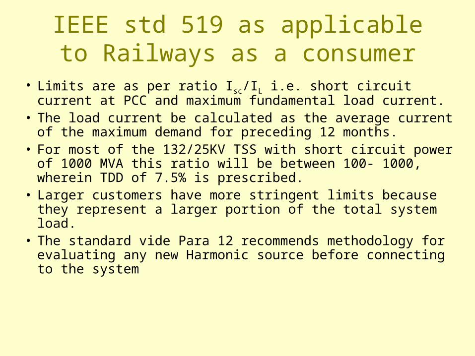
• Limits are as per ratio Isc/IL i.e. short circuit current at PCC and maximum fundamental load current.
• The load current be calculated as the average current of the maximum demand for preceding 12 months.
• For most of the 132/25KV TSS with short circuit power of 1000 MVA this ratio will be between 100- 1000, wherein TDD of 7.5% is prescribed.
• Larger customers have more stringent limits because they represent a larger portion of the total system load.
• The standard vide Para 12 recommends methodology for evaluating any new Harmonic source before connecting to the system
IEEE std 519 as applicable to Railways as a consumer
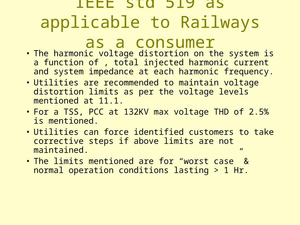
• The harmonic voltage distortion on the system is a function of , total injected harmonic current and system impedance at each harmonic frequency.
• Utilities are recommended to maintain voltage distortion limits as per the voltage levels mentioned at 11.1.
• For a TSS, PCC at 132KV max voltage THD of 2.5% is mentioned.
• Utilities can force identified customers to take corrective steps if above limits are not maintained.
• The limits mentioned are for “worst case” & normal operation conditions lasting > 1 Hr.
Controlling Harmonic currents
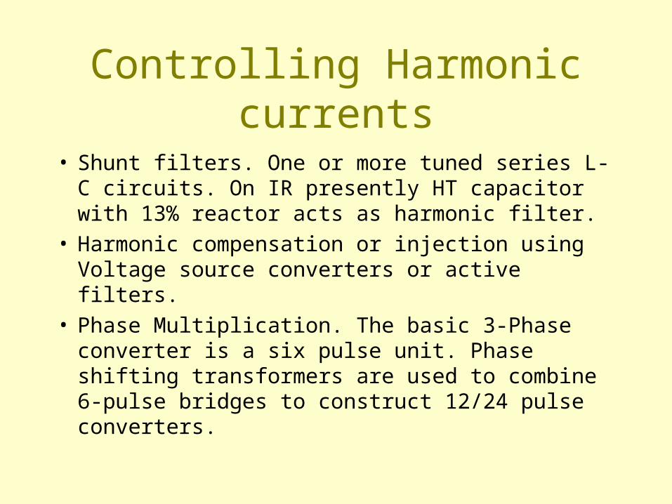
• Shunt filters. One or more tuned series L-C circuits. On IR presently HT capacitor with 13% reactor acts as harmonic filter.
• Harmonic compensation or injection using Voltage source converters or active filters.
• Phase Multiplication. The basic 3-Phase converter is a six pulse unit. Phase shifting transformers are used to combine 6-pulse bridges to construct 12/24 pulse converters.
Voltage unbalance
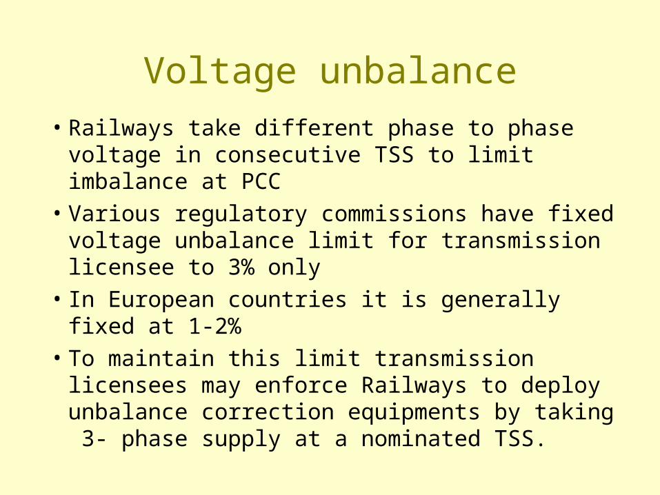
• Railways take different phase to phase voltage in consecutive TSS to limit imbalance at PCC
• Various regulatory commissions have fixed voltage unbalance limit for transmission licensee to 3% only
• In European countries it is generally fixed at 1-2% • To maintain this limit transmission licensees may
enforce Railways to deploy unbalance correction equipments by taking 3- phase supply at a nominated TSS.
Voltage disturbances
• Long term variations of > 1 minute are called under/over voltages, Railways monitor this.
• Short term variation of < 0.5 to 1.0 cycle are called sag, swell and flickers, this level of monitoring is not done in Railways.
• Voltage sag, swell and flickers affect sensitive electronic equipments.
• Series active filters or dynamic voltage restorers are used for correction.
Over voltages in traction supply system• IEC 61374 refers to over voltages in traction systems and
contains comparative data from China, France, UK, USSR, Chezkoslovakia and Japan.
• The over voltages of traction system are classified into Temporary over voltages, switching / lightening over voltages.
• Temporary over voltages are of few seconds to minutes, causes may be earth faults on the 3 phase system supply to Railways, load dropping in conjunction with supply stations, resonance of filter banks, over compensation etc.
• Switching over voltages of 250 to 5000 micro seconds may occur due to switching operations and faults.
Over voltages in traction supply system
• The over voltages tolerances, limits in different Railway systems world over vary widely because of differences in system characteristics e.g.
• Line impedances and configurations like single line/ double line, BT/AT systems, transformer types and connections, parameters of supply system, type of shunt/series compensation and filtering techniques adopted, load and protection coordination etc.
Power factor improvement on IR
• 1975 onward different electricity boards specified the minimum PF to be maintained.
• IR started providing fixed capacitor banks by 1982.
• IR was paying penalties for low PF up to 11.83 crores in year 1990-91.
• Penalties on account of low PF are now reducing.• Other incidental benefits accrued were reduction
in MD, Harmonics, line current and voltage drop.
Limitations with Fixed Capacitors• Not feasible to achieve PF higher than 0.9 due to
problems of high voltages under light load conditions and possibility of parallel resonance at a harmonic frequency causing distortion of voltage waveform.
• Not possible to avail benefit of incentives on PF above 0.95 and Unity.
• Frequent switching on/off of CB may results system instability, damage to breakers.
• States like MP, TN and Chatisgarh have intended to calculate apparent power by adding the leading KVAR generated by Fixed capacitors hence under light load conditions. Average chargeable PF shall be less while KVAh MD shall increase.
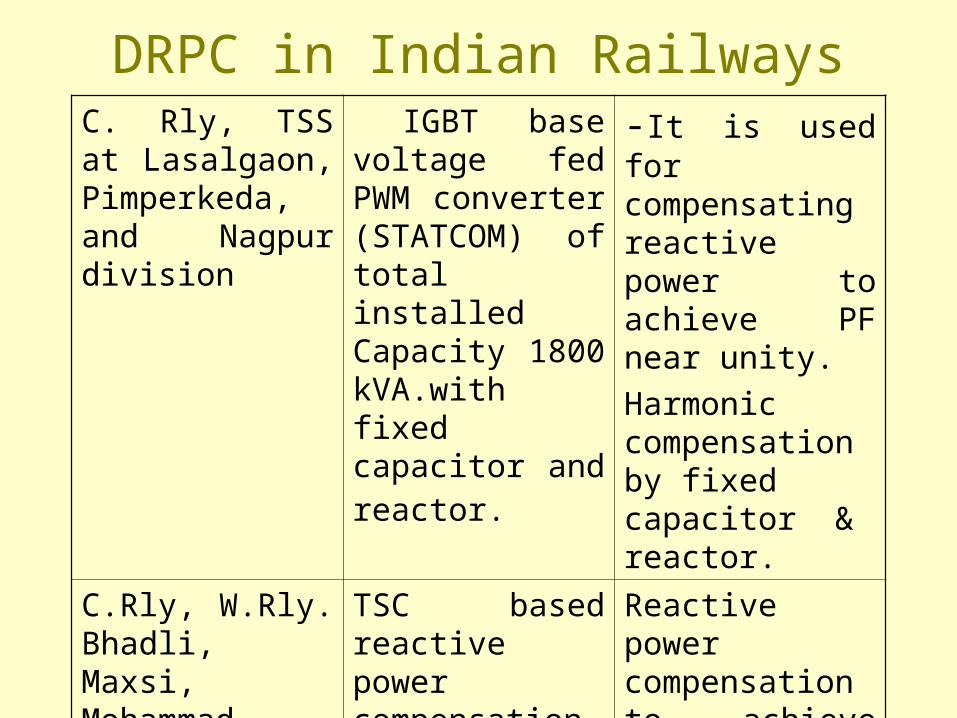
DRPC in Indian RailwaysC. Rly, TSS at Lasalgaon, Pimperkeda, and Nagpur division
IGBT base voltage fed PWM converter (STATCOM) of total installed Capacity 1800 kVA.with fixed capacitor and reactor.
-It is used for compensating reactive power to achieve PF near unity.
Harmonic compensation by fixed capacitor & reactor.
C.Rly, W.Rly. Bhadli, Maxsi, Mohammad kheda
TSC based reactive power compensation.
Reactive power compensation to achieve near unity PF
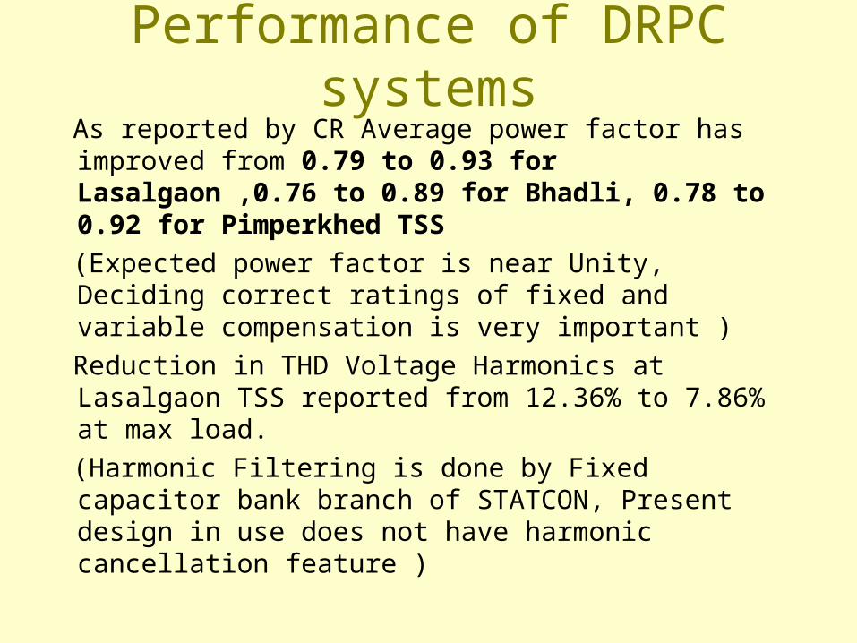
Performance of DRPC systemsAs reported by CR Average power factor has improved from 0.79 to 0.93 for Lasalgaon ,0.76 to 0.89 for Bhadli, 0.78 to 0.92 for Pimperkhed TSS
(Expected power factor is near Unity, Deciding correct ratings of fixed and variable compensation is very important )
Reduction in THD Voltage Harmonics at Lasalgaon TSS reported from 12.36% to 7.86% at max load.
(Harmonic Filtering is done by Fixed capacitor bank branch of STATCON, Present design in use does not have harmonic cancellation feature )
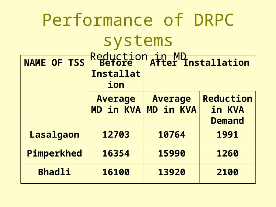
Performance of DRPC systemsReduction in MD
NAME OF TSS Before Installation
After Installation
AverageMD in KVA
AverageMD in KVA
Reduction in KVA
Demand
Lasalgaon 12703 10764 1991
Pimperkhed 16354 15990 1260
Bhadli 16100 13920 2100
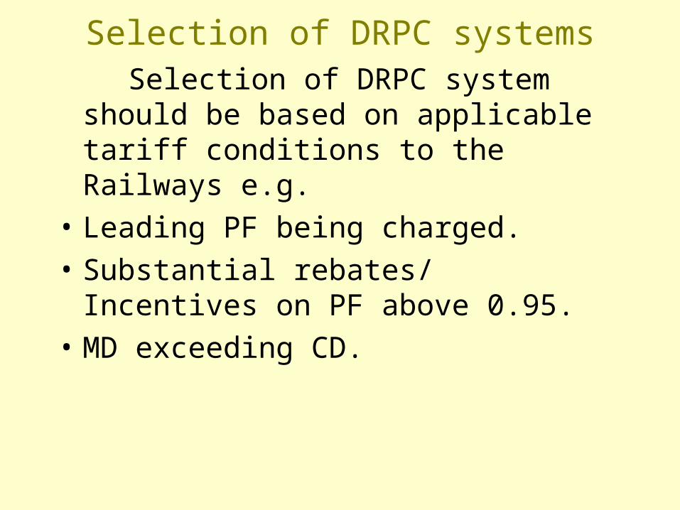
Selection of DRPC systems Selection of DRPC system should be based
on applicable tariff conditions to the Railways e.g.
• Leading PF being charged.
• Substantial rebates/ Incentives on PF above 0.95.
• MD exceeding CD.
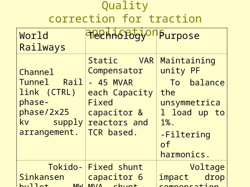
International examples of Power Qualitycorrection for traction applications
World Railways Technology Purpose
Channel Tunnel Rail link (CTRL) phase-phase/2x25 kv supply arrangement.
Static VAR Compensator
- 45 MVAR each Capacity Fixed capacitor & reactors and TCR based.
Maintaining unity PF
To balance the unsymmetrical load up to 1%.
-Filtering of harmonics.
Tokido-Sinkansen bullet MW load each. 3-phase 154KV/2x25 KV single phase.
Fixed shunt capacitor 6 MVA, shunt Active filter GTO based, voltage fed inverter 16x3 = 48 MVA.
Voltage impact drop compensation.
-Variation and imbalance of 3.6% is corrected to 1%.
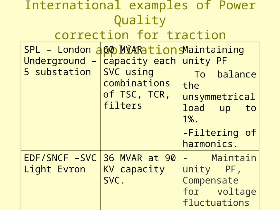
International examples of Power Qualitycorrection for traction applications
SPL – London Underground – 5 substation
60 MVAR capacity each SVC using combinations of TSC, TCR, filters
Maintaining unity PF
To balance the unsymmetrical load up to 1%.
-Filtering of harmonics.
EDF/SNCF –SVC Light Evron
36 MVAR at 90 KV capacity SVC.
- Maintain unity PF, Compensate for voltage fluctuations and unbalances as well as active filtering
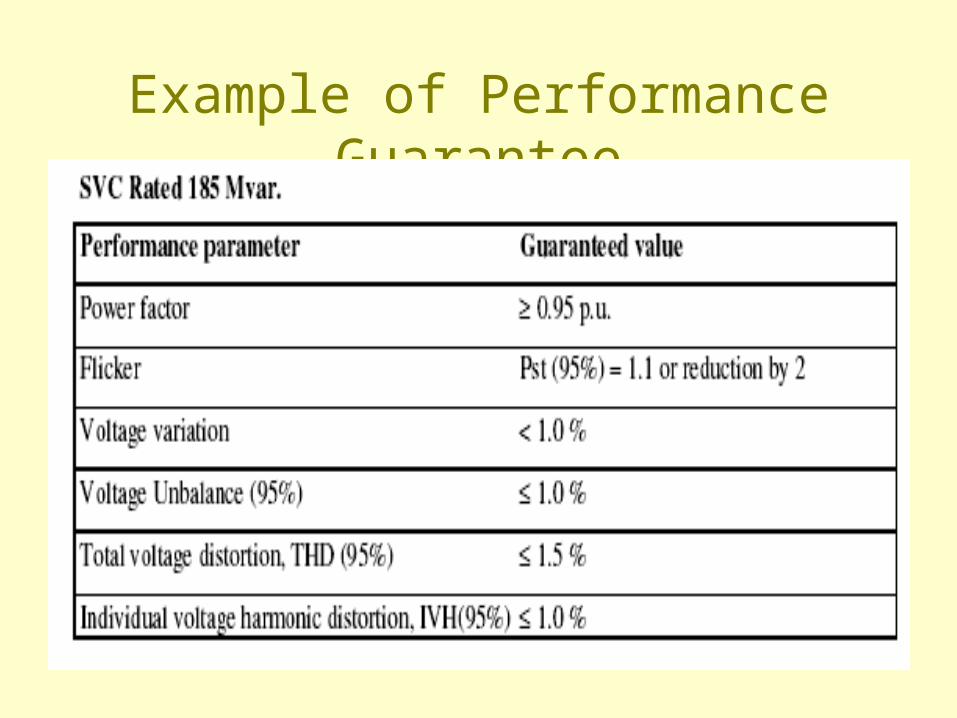
Example of Performance Guarantee
What needs to be done• Select an appropriate PF correction method
according to applicable tariff conditions.
• HT capacitors can not provide PF above 0.9 and are not advantageous if leading VAR are added to calculate apparent power, Use of DRPC shall be beneficial in such condition.
• Tariff, supply code and other directives of regulatory commissions on harmonics, voltage parameters etc must be watched.
What needs to be done
• Measure harmonic distortion, and monitoring of voltage surges by providing suitable power analyzers with data loggers for generating a data base for sufficiently long duration.
• Develop a total power quality correction strategy which should include PF, Harmonics and voltage unbalance correction (by taking 3-ø supply at TSS).
• Conduct trials for the same at one or two TSS on IR for extended period.