power ow controlling using sssc based on matrix converter...
TRANSCRIPT
Turk J Elec Eng & Comp Sci
(2016) 24: 1461 – 1473
c⃝ TUBITAK
doi:10.3906/elk-1311-127
Turkish Journal of Electrical Engineering & Computer Sciences
http :// journa l s . tub i tak .gov . t r/e lektr ik/
Research Article
Power flow controlling using SSSC based on matrix converter via SA-PSO
algorithm
Ali AJAMI∗, Farhad MOHAJEL KAZEMIDepartment of Electrical Engineering, Azarbaijan Shahid Madani University, Tabriz, Iran
Received: 15.11.2013 • Accepted/Published Online: 31.03.2014 • Final Version: 23.03.2016
Abstract: The static synchronous series compensator (SSSC) is one of the series flexible AC transmission system
(FACTS) devices that can be used in power flow control and reactive compensation in transmission lines. In this paper,
a new configuration of SSSC based on a matrix converter is presented. The proposed SSSC has some advantages such
as elimination of the DC link, bidirectional power flow control capability, fast dynamic response, and simple control
system. By presenting a switching algorithm for the AC-AC matrix converter, an almost sinusoidal series compensation
voltage is injected to the transmission line with low total harmonic distortion. In this paper, a modified particle swarm
optimization (PSO) algorithm is used to obtain the optimal parameters of a power flow controller. The modified PSO
algorithm is simulated annealing-PSO. Application of the proposed SSSC in different operating points is simulated by
MATLAB/Simulink software. Simulation results verify that the designed control system enables the proposed SSSC
topology with independent control of active and reactive power flow in transmission lines. Presented simulation results
confirm the validity and effectiveness of the suggested SSSC in power flow controlling system.
Key words: FACTS devices, static synchronous series compensator, matrix converter, power flow control, SA-PSO
optimization method
1. IntroductionRecently, use of flexible AC transmission system (FACTS) devices has been actively promoted to control power
flow in a power transmission system. Power system oscillations damping, transient stability improvement,
and provision of voltage stability can be obtained by adding a supplementary control system to the FACTS
device controllers. FACTS devices are based on grid-connected power electronics converters with high-power
semiconductor technology [1].
FACTS devices can be classified into two types as line-commutated and self-commutated, which are
based on the characteristics of the power semiconductors. In the line-commutated devices, in order to inject
the controllable reactive power, FACTS devices operate under phase control based on thyristor technology.
Self-commutated devices are based on gate turn-off semiconductors such as IGBT, IGCT, or GTO. In this
type, FACTS devices generate AC voltages and currents with controllable phase angle and magnitude through
a voltage source converter. The static synchronous series compensator (SSSC) and the static compensator
(STATCOM) are one of the series and shunt topologies of FACTS controllers, respectively. In addition, the
interline power flow controller (IPFC) and the unified power flow controller (UPFC) are the combination of series
and shunt structures. This classification has been confirmed in the field of power flow control in transmission
lines [2].
∗Correspondence: [email protected]
1461
AJAMI and MOHAJEL KAZEMI/Turk J Elec Eng & Comp Sci
In the conventional FACTS devices based on power electronics converters, a DC link is required for
interconnecting two AC systems. This configuration is not mandatory and can be removed using proper AC-
AC conversion [3]. Therefore, using the AC-AC converters without a DC link will be able to eliminate the
energy-storing elements. A converter with this characteristic is called a matrix converter. In comparison with
the multistage AC/DC/AC converters, the matrix converter is smaller and also more reliable because of its
requirements of energy storage elements. Moreover, output voltage and input current in matrix converter are
directly obtained by the input voltage and output current, respectively [4,5]. In addition to not requiring the DC
link, the matrix converters have advantages such as almost sinusoidal waveforms of input and output currents,
and controllable input power factor. In motor drive applications, matrix converters can be operated in all four
quadrants of the torque-speed plane.
Control of matrix converters can be performed using several modulation techniques [6–10]. Each switching
method uses different features of matrix converters and each one has its own advantages and limitations.
In this paper, a new configuration of SSSC based on a matrix converter is presented to control the
active and reactive power flow in a transmission line. The pulse width modulation (PWM) method is used
for controlling the matrix converter. The main advantages of this topology are elimination of the DC link,
simultaneous control of the active and reactive power flow, simplicity of the control system, small amounts of
output passive filter elements, fast response in various conditions, and acceptable performance in voltage sag
(or swell).
To achieve the mentioned advantages, a proper control system is required. In this paper, to obtain the
optimal parameters of the power flow controller, a modified particle swarm optimization (PSO) algorithm is
used. The modified PSO algorithm is simulated annealing-particle swarm optimization (SA-PSO).
The proposed SSSC is modeled by MATLAB/Simulink software and simulation results are presented to
indicate the good performance of the novel configuration of SSSC in normal operation and during symmetrical
and asymmetrical fault conditions.
2. Proposed configuration of SSSC based on matrix converter
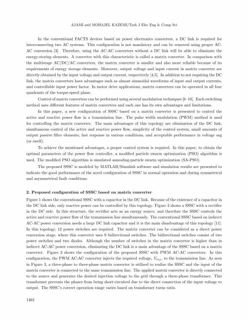
Figure 1 shows the conventional SSSC with a capacitor in the DC link. Because of the existence of a capacitor in
the DC link side, only reactive power can be controlled by this topology. Figure 2 shows a SSSC with a rectifier
in the DC side. In this structure, the rectifier acts as an energy source, and therefore the SSSC controls the
active and reactive power flow of the transmission line simultaneously. The conventional SSSC based on indirect
AC-AC power conversion needs a large DC link capacitor and it is the main disadvantage of this topology [11].
In this topology, 12 power switches are required. The matrix converter can be considered as a direct power
conversion stage, where this converter uses 9 bidirectional switches. The bidirectional switches consist of two
power switches and two diodes. Although the number of switches in the matrix converter is higher than in
indirect AC-AC power conversion, eliminating the DC link is a main advantage of the SSSC based on a matrix
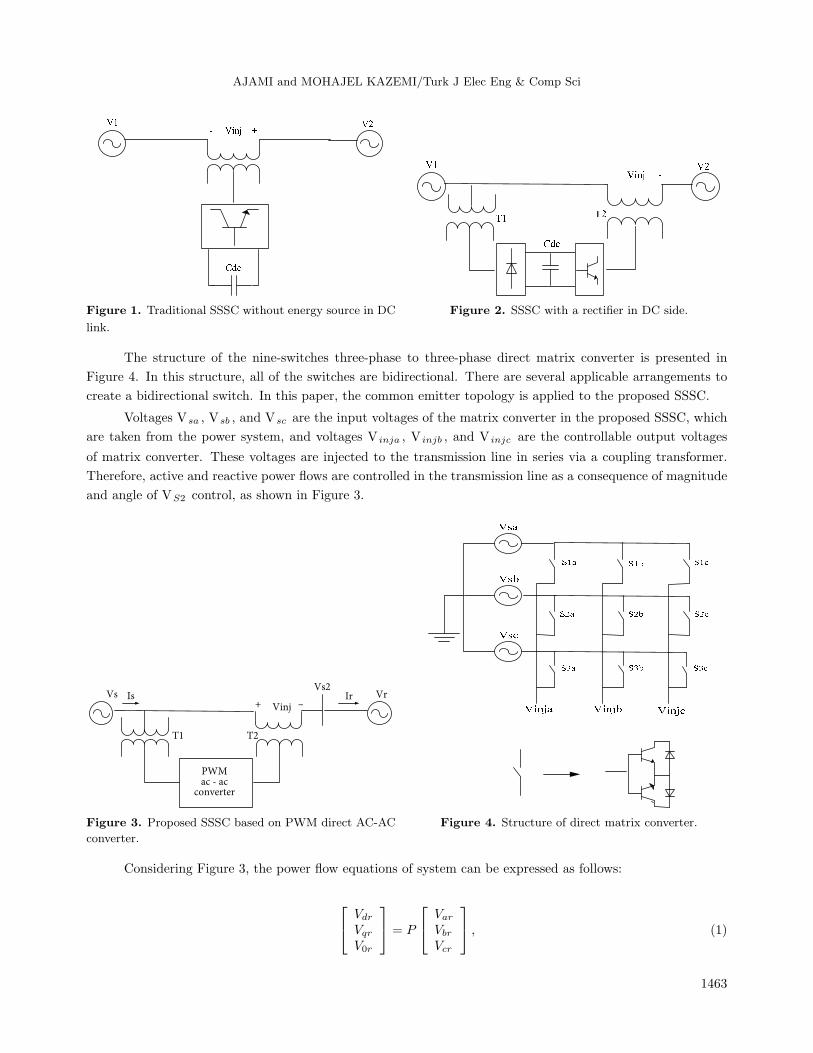
converter. Figure 3 shows the configuration of the proposed SSSC with PWM AC-AC converters. In this
configuration, the PWM AC-AC converter injects the required voltage, Vinj , to the transmission line. As seen
in Figure 3, a three-phase to three-phase matrix converter is utilized to realize the SSSC and the input of the
matrix converter is connected to the same transmission line. The applied matrix converter is directly connected
to the source and generates the desired injection voltage to the grid through a three-phase transformer. This
transformer prevents the phases from being short-circuited due to the direct connection of the input voltage to
output. The SSSC’s correct operation range varies based on transformer turns ratio.
1462
AJAMI and MOHAJEL KAZEMI/Turk J Elec Eng & Comp Sci
Figure 1. Traditional SSSC without energy source in DC
link.
Figure 2. SSSC with a rectifier in DC side.
The structure of the nine-switches three-phase to three-phase direct matrix converter is presented in
Figure 4. In this structure, all of the switches are bidirectional. There are several applicable arrangements to
create a bidirectional switch. In this paper, the common emitter topology is applied to the proposed SSSC.
Voltages Vsa , Vsb , and Vsc are the input voltages of the matrix converter in the proposed SSSC, which
are taken from the power system, and voltages V inja , V injb , and V injc are the controllable output voltages
of matrix converter. These voltages are injected to the transmission line in series via a coupling transformer.
Therefore, active and reactive power flows are controlled in the transmission line as a consequence of magnitude
and angle of VS2 control, as shown in Figure 3.
Vs VrVinj+ –
PWMac - ac
converter
Is IrVs2
T1 T2
Figure 3. Proposed SSSC based on PWM direct AC-AC
converter.
Figure 4. Structure of direct matrix converter.
Considering Figure 3, the power flow equations of system can be expressed as follows:
Vdr
Vqr
V0r
= P
Var
Vbr
Vcr
, (1)
1463
AJAMI and MOHAJEL KAZEMI/Turk J Elec Eng & Comp Sci
IdrIqrI0r
= P
IarIbrIcr
, (2)
Pr = VdrIdr + VqrIqr, (3)
Qr = VdrIqr − VqrIdr, (4)
where Vr ,Ir are receiving voltage and current, respectively, and Pr ,Qr are active and reactive power of the
receiving end side, respectively. P is Park’s transformation.
To control active and reactive power, the matrix converter injects voltage to the transmission line and
controls the voltage of Vs2 as follows:
Vs2 = Vs + Vinj . (5)
Since the DC link has been eliminated, the phase and magnitude of Vs2 are controllable by V inj similar to
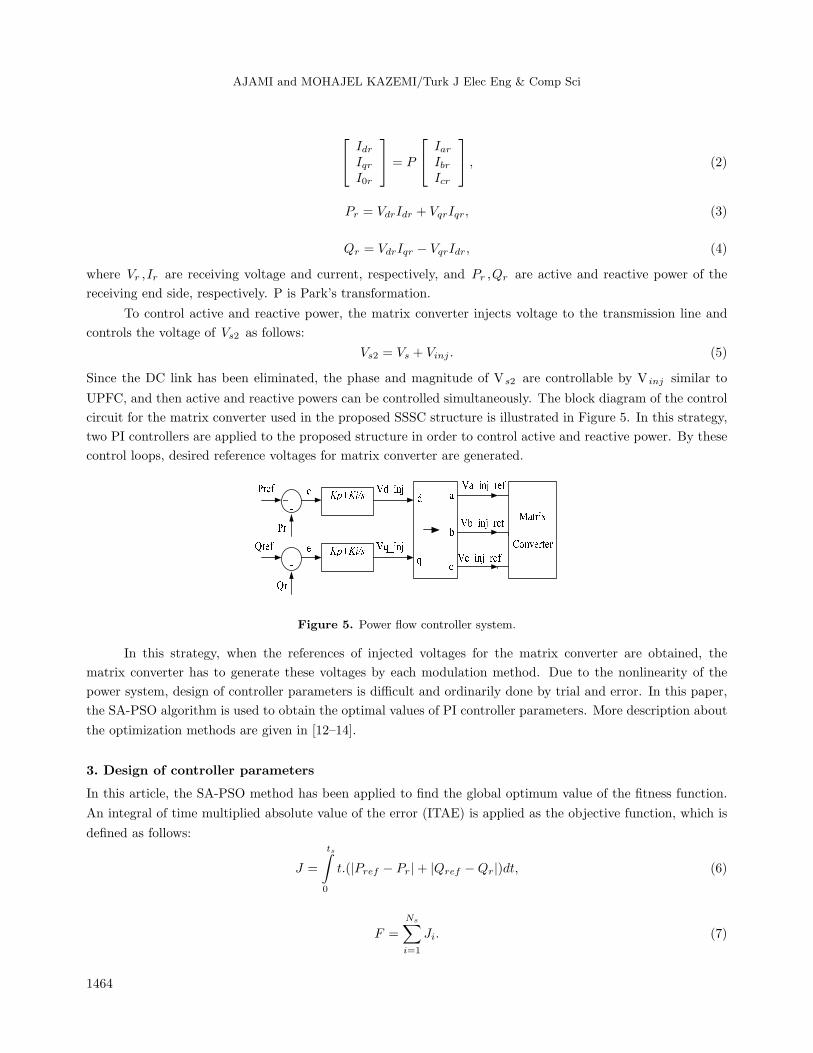
UPFC, and then active and reactive powers can be controlled simultaneously. The block diagram of the control
circuit for the matrix converter used in the proposed SSSC structure is illustrated in Figure 5. In this strategy,
two PI controllers are applied to the proposed structure in order to control active and reactive power. By these
control loops, desired reference voltages for matrix converter are generated.
Figure 5. Power flow controller system.
In this strategy, when the references of injected voltages for the matrix converter are obtained, the
matrix converter has to generate these voltages by each modulation method. Due to the nonlinearity of the
power system, design of controller parameters is difficult and ordinarily done by trial and error. In this paper,
the SA-PSO algorithm is used to obtain the optimal values of PI controller parameters. More description about
the optimization methods are given in [12–14].
3. Design of controller parameters
In this article, the SA-PSO method has been applied to find the global optimum value of the fitness function.
An integral of time multiplied absolute value of the error (ITAE) is applied as the objective function, which is
defined as follows:
J =
ts∫0
t.(|Pref − Pr|+ |Qref −Qr|)dt, (6)
F =
Ns∑i=1
Ji. (7)
1464
AJAMI and MOHAJEL KAZEMI/Turk J Elec Eng & Comp Sci
In Eqs. (6) and (7), ts is the simulation time and Ns is the total number of operating points applied to
the optimization performed. The simulation period in the objective function calculation is determined by the
time-domain simulation of the test power system. Controller parameter bounds should be considered in the
optimization problem; minimize J subject to:
Kminp ≤ Kp ≤ Kmax
p
Kmini ≤ Ki ≤ Kmax
i
. (8)
In this case, typical ranges of the optimized parameters are [0.01–220] for Kp and [0.01–2.5] forKi . One of the
metaheuristic methods to solve difficult optimization problems is simulated annealing (SA). The SA method is
based on an analogy between combinatorial optimization problems and statistical mechanics systems [15]. In
the SA algorithm a global optimum is obtained by ‘downwards’ or ‘upwards’ moves, and the most important
characteristic of SA is the probabilistic jumping property, i.e. a worse solution may be accepted as the new
solution. Moreover, by adjusting the temperature, such a jumping probability can be controlled [13].
In the original PSO, step sizes are constant and this is the same for all the particles, so convergence
of this algorithm before providing an accurate solution is slow. To overcome this problem and make faster
movements, new step sizes can be modified and accelerate the convergence rate. In each iteration, the value
of the objective function is a benchmark that presents the comparative upgrading of this movement in respect
to the previous iteration. Thus, the difference between the values of the objective function in the different
iterations can be selected as the accelerators. To achieve adaptive movements, two additional coefficients are
added to the original step sizes in the PSO algorithm, and therefore the rate-updating formula can be obtained
from Eq. (10).
Oi = gi
/L∑
j=1
gj (i = 1, 2, ..., L) (9)
vid (t+ 1) = W ∗ vid (t) + C1 ∗ rand1 ∗ (f (Pid (t)))− f (xid (t)) ∗ (Pid − xid (t))
+C2 ∗ rand2 ∗ (f (Pgd (t)))− f (xid (t)) ∗ (Pgd − xid (t)) (10)
In Eqs. (9) and (10), vid is the velocity of particle i in dimension d ,C1 and C2 are two acceleration coefficients,
and W is the inertia weight factor. The best position of the ith particle in dimension d is determined by Pid
and the best position among all particles in the swarm is Pgd . rand1 and rand2 are the random functions in
the range [0, 1]. f(Pid(t)) is the best fitness function that is found by the ith particle and f(Pgd(t)) is the best
fitness function found by the swarm up to now. The SA-PSO algorithm has fast convergence but not premature
convergence. In the SA-PSO algorithm, every point that is found by Eq. (11) has been named by the temporary
point xid(p)(xid(p) = xid (t +1)). For all particles, if xid(p) is better than xid(t), it will be accepted, but when
it is worse than xid(t), we will accept it with the probability of exp( −∆/T ), (∆ = f(xid(p))− f(xid(t))) given
below:
xid(p) = xid(t) + vid(t)
∆ = f(xid(p))− f(xid(t))
If ∆ ≺ 0 then xid(t+ 1) = xid(p)
If ∆ ≥ 0 then
xid(d) = xid(p) + α ∗ vid(t)xid(t+ 1) = xid(d)
, (11)
1465
AJAMI and MOHAJEL KAZEMI/Turk J Elec Eng & Comp Sci
a =
+1 probability = e−∆/t
−1 otherwise
. (12)
The speed of the resulting particles has been increased by increasing inertia weight, W, and decreased by
decreasing inertia weight, W. Thus, an iteration-dependent weight factor is often a fixed factor. Eq. (13)
describes the functional form of this weight factor:
W = Wmax −Wmax −Wmin
Niter× iter, (13)
where iter is number of iteration (iter = 1, 2,...,Niter), Niter is the maximum number of iterations (Niter =
100), and Wmax and Wmin are chosen to be 0.9 and 0.1, respectively.
4. Control strategy of matrix converter
The PWM technique is one of the common control methods that can be used for controlling the waveform of
the output voltage. In this method, the duty cycle of switches has been changed at a high switching frequency
to achieve output voltage and current at the low frequency. By using this method, the desired output voltage
is synthesized by the sampled segments of the input voltages [16].
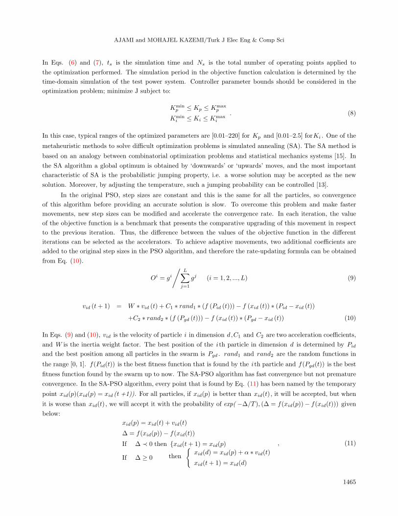
In this paper, a PWM-based control strategy is used as follows: first, voltages Vsa , Vsb , and Vsc are
compared with each other and this comparison leads to each period of the input voltage, which is divided into
six equal areas (each area being 60). The reason for choosing each area being equal to 60 is that the peak
equation of voltages is constant, as shown in Figure 6.
0 0.01 0.02 0.03 0.04 0.05 0.06 0.07 0.08 0.09 0.1
–V
V
Time(s)
V(v
)
max
max
Figure 6. Peak voltage of vmax(t) , vmin(t).
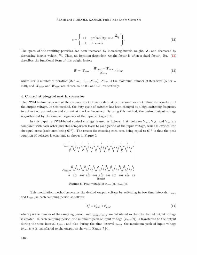
This modulation method generates the desired output voltage by switching in two time intervals, tmax
and tmin , in each sampling period as follows:
T js = tjmax + tjmin, (14)
where j is the number of the sampling period, and tmax , tmin are calculated so that the desired output voltage
is created. In each sampling period, the minimum peak of input voltage (vmin(t)) is transferred to the output
during the time interval tmin , and also during the time interval tmax the maximum peak of input voltage
(vmax(t)) is transferred to the output as shown in Figure 7 [4].
1466
AJAMI and MOHAJEL KAZEMI/Turk J Elec Eng & Comp Sci
0 0.5 1 1.5 2 2.5 3x 10
–3
–V
V
Time(s)
Vo
ut(
v)
tmax
max
max
tmin
Figure 7. Output voltage for proposed switching method.
vmax(t) and vmin(t) in each sample time can be defined as follows:
vmax(t) = Vmax sin(ωit+ θmax)
vmin(t) = Vmax sin(ωit+ θmin), (15)
where θmax and θmin signify the phases of vmax (t) and vmin (t), and Vmax is the peak value. Notice that
switching frequency is very high (fs >> fi and fs >> fo), so the average of the output voltage can be written
as below:
vout(t) =tjmaxvmax(t) + tjminvmin(t)
Ts. (16)
Considering Eq. (16), in this technique the desired output voltage can be generated by the combination of
vmax(t) and vmin(t) during time intervals tmax and tmin where the time intervals tmax , tmin have been
calculated as in Eq. (17).
tmax =Ts(v0ref (t)−vmin(t))
vmax(t)−vmin(t)
tmin = Ts − tmax
(17)
It is obvious that this control method is independent for each phase of the output voltage. In other word, Eqs.
(16) and (17) can be rewritten for each phase of the output voltage. Therefore, the matrix converter can be
controlled independently for each phase and generates various voltages in each phase of the output. In addition,
the desired output voltage can be generated even under unbalanced input voltages.
5. Simulation result
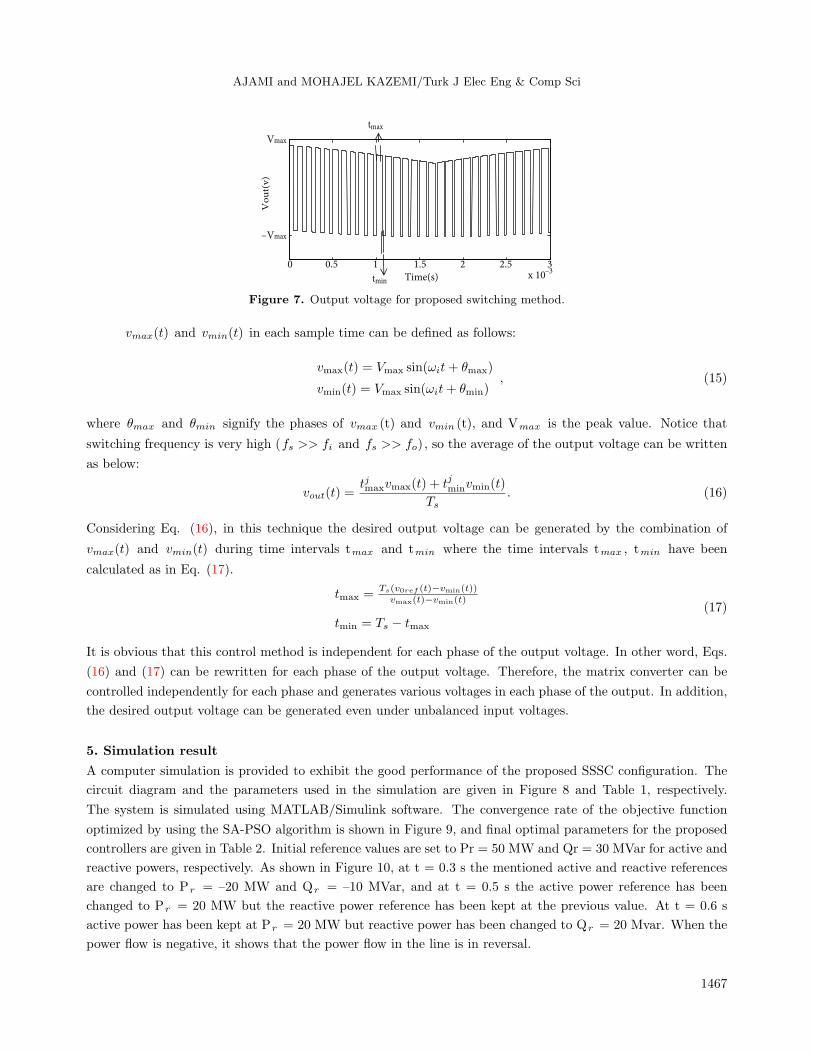
A computer simulation is provided to exhibit the good performance of the proposed SSSC configuration. The
circuit diagram and the parameters used in the simulation are given in Figure 8 and Table 1, respectively.
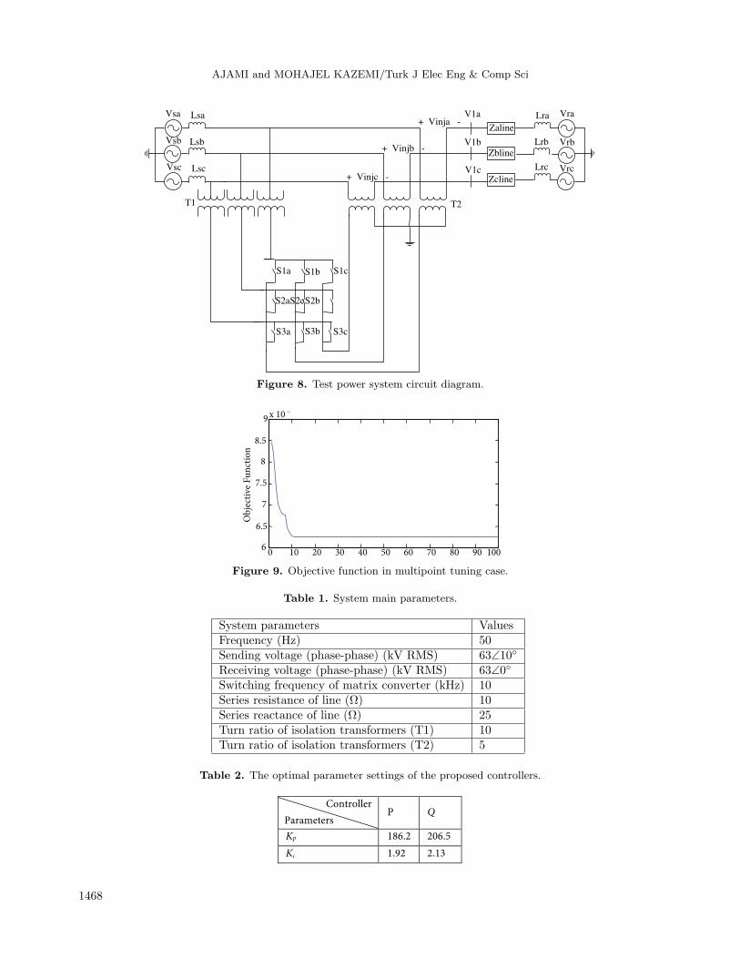
The system is simulated using MATLAB/Simulink software. The convergence rate of the objective function
optimized by using the SA-PSO algorithm is shown in Figure 9, and final optimal parameters for the proposed
controllers are given in Table 2. Initial reference values are set to Pr = 50 MW and Qr = 30 MVar for active and
reactive powers, respectively. As shown in Figure 10, at t = 0.3 s the mentioned active and reactive references
are changed to Pr = –20 MW and Qr = –10 MVar, and at t = 0.5 s the active power reference has been
changed to Pr = 20 MW but the reactive power reference has been kept at the previous value. At t = 0.6 s
active power has been kept at Pr = 20 MW but reactive power has been changed to Qr = 20 Mvar. When the
power flow is negative, it shows that the power flow in the line is in reversal.
1467
AJAMI and MOHAJEL KAZEMI/Turk J Elec Eng & Comp Sci
Vra
Zaline
Zbline
Zcline
+ Vinja -
S1a
S2b
S3b
S1b
S2aS2c
S3a
S1c
S3c
Vrb
Vrc
Lra
Lrb
Lrc
V1a
V1b
V1c
+ Vinjb -
+ Vinjc -
Vsa
Vsb
Vsc
Lsa
Lsb
Lsc
T1 T2
Figure 8. Test power system circuit diagram.
0 10 20 30 40 50 60 70 80 90 1006
6.5
7
7.5
8
8.5
9 x 10 –
Ob
ject
ive
Fu
nct
ion
Figure 9. Objective function in multipoint tuning case.
Table 1. System main parameters.
System parameters ValuesFrequency (Hz) 50Sending voltage (phase-phase) (kV RMS) 63∠10Receiving voltage (phase-phase) (kV RMS) 63∠0Switching frequency of matrix converter (kHz) 10Series resistance of line (Ω) 10Series reactance of line (Ω) 25Turn ratio of isolation transformers (T1) 10Turn ratio of isolation transformers (T2) 5
Table 2. The optimal parameter settings of the proposed controllers.
Controller
Parameters P
Q
Kp 186.2 206.5
Ki 1.92 2.13
1468
AJAMI and MOHAJEL KAZEMI/Turk J Elec Eng & Comp Sci
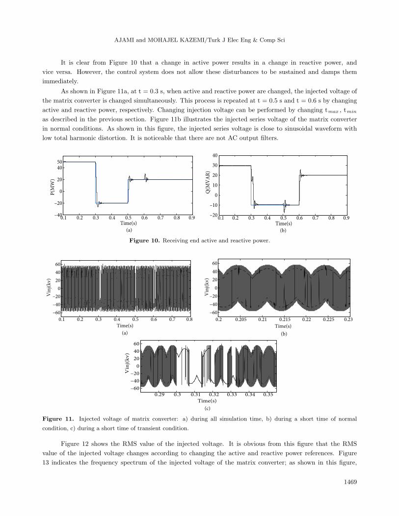
It is clear from Figure 10 that a change in active power results in a change in reactive power, and
vice versa. However, the control system does not allow these disturbances to be sustained and damps them
immediately.
As shown in Figure 11a, at t = 0.3 s, when active and reactive power are changed, the injected voltage of
the matrix converter is changed simultaneously. This process is repeated at t = 0.5 s and t = 0.6 s by changing
active and reactive power, respectively. Changing injection voltage can be performed by changing tmax , tmin
as described in the previous section. Figure 11b illustrates the injected series voltage of the matrix converter
in normal conditions. As shown in this figure, the injected series voltage is close to sinusoidal waveform with
low total harmonic distortion. It is noticeable that there are not AC output filters.
(a) (b)
0.1 0.2 0.3 0.4 0.5 0.6 0.7 0.8 0.9–40
–20
0
20
4050
Time(s)
P(M
W)
0.1 0.2 0.3 0.4 0.5 0.6 0.7 0.8 0.9–20
–10
0
10
20
30
40
Time(s)
Q(M
VA
R)
Figure 10. Receiving end active and reactive power.
(c)
0.29 0.3 0.31 0.32 0.33 0.34 0.35–60
–40
–20
0
20
40
60
Time(s)
Vin
j(k
v)
(a)
(b)
0.1 0.2 0.3 0.4 0.5 0.6 0.7 0.8
–60
–40
–20
0
20
40
60
Time(s)
Vin
j(k
v)
0.2 0.205 0.21 0.215 0.22 0.225 0.23
–60
–40
–20
0
20
40
60
Time(s)
Vin
j(k
v)
Figure 11. Injected voltage of matrix converter: a) during all simulation time, b) during a short time of normal
condition, c) during a short time of transient condition.
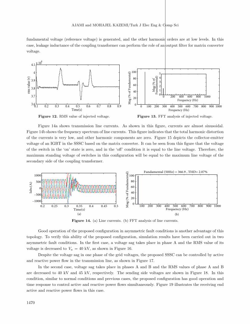
Figure 12 shows the RMS value of the injected voltage. It is obvious from this figure that the RMS
value of the injected voltage changes according to changing the active and reactive power references. Figure
13 indicates the frequency spectrum of the injected voltage of the matrix converter; as shown in this figure,
1469
AJAMI and MOHAJEL KAZEMI/Turk J Elec Eng & Comp Sci
fundamental voltage (reference voltage) is generated, and the other harmonic orders are at low levels. In this
case, leakage inductance of the coupling transformer can perform the role of an output filter for matrix converter
voltage.
0.1 0.2 0.3 0.4 0.5 0.6 0.7 0.8 0.93.6
3.7
3.8
3.9
4
4.1 x 10⁴
Time(s)
rms
valu
e (v
)
0 100 200 300 400 500 600 700 800 900 10000
20
40
60
80
100
Frequency (Hz)
Mag
(%
of
Fu
nd
amen
tal)
0 200 400 600 800 10000
1
2
3
4
5
Frequency (Hz)
Mag
(%
of
Fu
nd
amen
tal)
Figure 12. RMS value of injected voltage. Figure 13. FFT analysis of injected voltage.
Figure 14a shows transmission line currents. As shown in this figure, currents are almost sinusoidal.
Figure 14b shows the frequency spectrum of line currents. This figure indicates that the total harmonic distortion
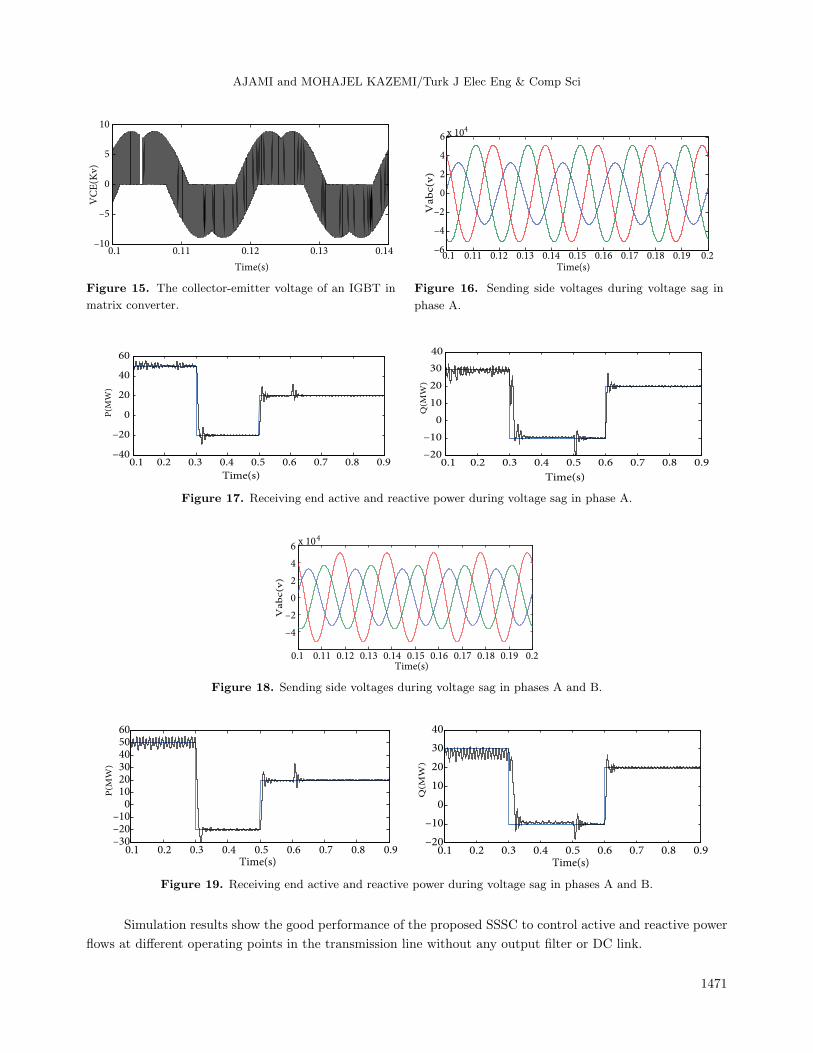
of the currents is very low, and other harmonic components are zero. Figure 15 depicts the collector-emitter
voltage of an IGBT in the SSSC based on the matrix converter. It can be seen from this figure that the voltage
of the switch in the ‘on’ state is zero, and in the ‘off’ condition it is equal to the line voltage. Therefore, the
maximum standing voltage of switches in this configuration will be equal to the maximum line voltage of the
secondary side of the coupling transformer.
(a) (b)
0.2 0.25 0.3 0.35 0.4 0.45 0.5
–1000
–500
0
500
1000
Time(s)
Iab
c(A
)
100 200 300 400 500 600 700 800 900 10000
20
40
60
80
100
Frequency (Hz)
Fundamental (50Hz) = 366.9 , THD= 2.07%
Mag
(%
of
Fu
nd
amen
tal)
Figure 14. (a) Line currents. (b) FFT analysis of line currents.
Good operation of the proposed configuration in asymmetric fault conditions is another advantage of this
topology. To verify this ability of the proposed configuration, simulation results have been carried out in two
asymmetric fault conditions. In the first case, a voltage sag takes place in phase A and the RMS value of its
voltage is decreased to Va = 40 kV, as shown in Figure 16.
Despite the voltage sag in one phase of the grid voltages, the proposed SSSC can be controlled by active
and reactive power flow in the transmission line, as shown in Figure 17.
In the second case, voltage sag takes place in phases A and B and the RMS values of phase A and B
are decreased to 40 kV and 45 kV, respectively. The sending side voltages are shown in Figure 18. In this
condition, similar to normal conditions and previous cases, the proposed configuration has good operation and
time response to control active and reactive power flows simultaneously. Figure 19 illustrates the receiving end
active and reactive power flows in this case.
1470
AJAMI and MOHAJEL KAZEMI/Turk J Elec Eng & Comp Sci
0.1 0.11 0.12 0.13 0.14–10
–5
0
5
10
Time(s)
VC
E(K
v)
0.1 0.11 0.12 0.13 0.14 0.15 0.16 0.17 0.18 0.19 0.2–6
–4
–2
0
2
4
6 x 10⁴
Time(s)
Vab
c(v
)
Figure 15. The collector-emitter voltage of an IGBT in
matrix converter.
Figure 16. Sending side voltages during voltage sag in
phase A.
0.1 0.2 0.3 0.4 0.5 0.6 0.7 0.8 0.9–40
–20
0
20
40
60
Time(s)
P(M
W)
0.1 0.2 0.3 0.4 0.5 0.6 0.7 0.8 0.9–20
–10
0
10
20
30
40
Time(s)
Q(M
W)
Figure 17. Receiving end active and reactive power during voltage sag in phase A.
0.1 0.11 0.12 0.13 0.14 0.15 0.16 0.17 0.18 0.19 0.2
–4
–2
0
2
4
6x 10⁴
Time(s)
Vab
c(v
)
Figure 18. Sending side voltages during voltage sag in phases A and B.
0.1 0.2 0.3 0.4 0.5 0.6 0.7 0.8 0.9–30–20–10
0102030405060
Time(s) Time(s)
P(M
W)
0.1 0.2 0.3 0.4 0.5 0.6 0.7 0.8 0.9–20
–10
0
10
20
30
40
Q(M
W)
Figure 19. Receiving end active and reactive power during voltage sag in phases A and B.
Simulation results show the good performance of the proposed SSSC to control active and reactive power
flows at different operating points in the transmission line without any output filter or DC link.
1471
AJAMI and MOHAJEL KAZEMI/Turk J Elec Eng & Comp Sci
6. Conclusion
In this paper, a novel structure of SSSC based on a matrix converter is proposed. The proposed power circuit
topology does not require any DC link and is supplied from its power system. The proposed topology injects
an almost sinusoidal series voltage using a direct AC-AC matrix converter.
Using the optimal design of controller parameters by the SA-PSO algorithm, the output voltage of
the matrix converter can track the reference waveforms exactly. The proposed topology compared with the
conventional SSSC has the following advantages:
• Simple control system of the proposed SSSC based on matrix converter.
• Elimination of DC link in input and passive filter in the output of proposed SSSC.
• Acceptable time response of proposed SSSC according to the simulation results.
• Bidirectional power flow in proposed configuration.
• Robust against symmetrical and asymmetrical voltage sages.
Simulation results validate the ability of the proposed SSSC to control active and reactive powers of a
transmission line in normal and faulty conditions.
References
[1] Park JW, Harley RG, Venayagamoorthy GK. New internal optimal neurocontrol for a series FACTS device in a
power transmission line. Neural Networks 2003; 16: 881–890.
[2] Bhattacharya S, Fardenesh B, Sherpling B. Convertible static compensator: voltage source converter based FACTS
application in the New York 345 kV transmission system. In: Proceedings of the 5th International Power Electronics
Conference; April 2005; Niigata, Japan.
[3] Mancilla-David F, Bhattacharya S, Venkataramanan G. A comparative evaluation of series power-flow controllers
using DC- and AC-link converters. IEEE T Power Deliver 2008; 23: 985–996.
[4] Babaei E, Kangarlu MF. A new topology for dynamic voltage restorers without DC link. In: IEEE Symposium on
Industrial Electronics and Applications; 4–6 October 2009; Kuala Lumpur, Malaysia. pp. 1016–1021.
[5] Hojabri H, Mokhtari H, Chang L. A generalized technique of modeling, analysis, and control of a matrix converter
using SVD. IEEE T Ind Electron 2011; 58: 949–959.
[6] Nguyen HM, Lee H, Chun T. Input power factor compensation algorithms using a new direct-SVM method for
matrix converter. IEEE T Ind Electron 2011; 58: 232–243.
[7] Alesina A, Venturini MGB. Solid-state power conversion: a Fourier analysis approach to generalized transformer
synthesis. IEEE T Circuits Syst 1981; 28: 319–330.
[8] Alesina A, Venturini MGB. Analysis and design of optimum amplitude nine-switch direct AC-AC converters. IEEE
T Power Electr 1989; 4: 101–112.
[9] Tadano Y, Urushibata S, Nomuro M, Sato Y, Ishida M. Direct space vector PWM strategies for three-phase to
three-phase matrix converter. In: Proceedings of the IEEE Power Conversion Conference; 2–5 April 2007; Nagoya,
Japan. pp. 1064–1071.
[10] Klumpner C, Blaabjerg F, Boldea I, Nielsen P. New modulation method for matrix converters. IEEE T Ind Appl
2006; 42: 1234–1246.
[11] Barragan-Villarejo M, Venkataramanan G, Mancilla-David F, Maza-Ortega JM, Gomez-Exposito A. Dynamic
modelling and control of a shunt-series power flow controller based on AC-link. IET Gener Transm Distrib 2012; 6:
792–802.
1472

AJAMI and MOHAJEL KAZEMI/Turk J Elec Eng & Comp Sci
[12] Ajami A, Asadzadeh H. Damping of power system oscillations using UPFC based multipoint tuning AIPSO-SA
algorithm. Gazi University Journal of Science 2011; 24: 791–804.
[13] Ajami A, Asadzadeh H. AIPSO-SA based approach for power system oscillation damping with STATCOM. Journal
of International Review on Electrical Engineering 2010; 5: 1151–1158.
[14] Ajami A, Aghajani G, Pourmahmood M. Optimal location of FACTS devices using adaptive particle swarm
optimization hybrid with simulated annealing. J Electr Eng Technol 2010; 5: 179–190.
[15] Laarhoven PJMV, Aarts EHL. Simulated Annealing: Theory and Applications. 1st ed. Dordrecht, the Netherlands:
D. Reidel Publishing Company, 1987.
[16] Babaei E. A new PWM based control method for forced commutated cycloconverters. Energ Convers Manage 2012;
53: 305–313.
1473