power grid corporation of india limited presentation on ‘free governor operation” by d.k.guru...
TRANSCRIPT

POWER GRID CORPORATION OF POWER GRID CORPORATION OF INDIA LIMITEDINDIA LIMITED
Presentation on Presentation on
‘‘FREE GOVERNOR OPERATION”FREE GOVERNOR OPERATION”
By D.K.Guru & S.P.BarnwalBy D.K.Guru & S.P.Barnwal
FREE GOVERNOR OPERATION
WHYFREQ COMPARISION
MAY-02 & MAY-03
GOVERNOR
BEFORE GOVERNORGOVERNOR RESPONSE
IN NER
DEAD BAND GOVERNOR TIME LAG
BLOCKED GOVERNOR
ROLE
DROOPFREQUENCY DECAY RATE BACKLASH
TYPES OF CONTROLSDROOP RESPONSE IN SR
ABT & GOVERNOR
ADVANTAGES
GOVERNOR TYPES
TIME DELAY
CHARACTERISTICS
PROBLEMS A FINAL WORD
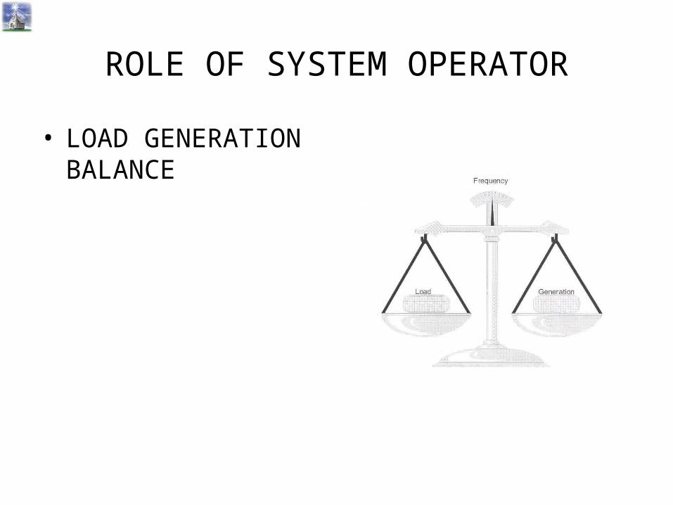
ROLE OF SYSTEM OPERATOR
• LOAD GENERATION BALANCE
50

WHY DOES FREQUENCY DROP ?WHY DOES FREQUENCY DROP ?
Sudden addition of load causes a drop in frequency.
An increased load is supplied through an increase in the load angle by which the rotor lags the stator field.
It means a loss of Kinetic Energy of the rotating M/c and a slower speed of rotation i.e. a lower frequency.
f = (P/2) X (N/60)
Where f = frequency of the system
P = no of poles of the M/c.
N = rpm of the M/c.
• Load Frequency control
• Free Governor Opertaion
• Under Frequency Operation
PRIMARY CONTROLSPRIMARY CONTROLS
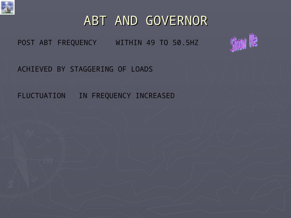
ABT AND GOVERNORABT AND GOVERNOR
POST ABT FREQUENCY WITHIN 49 TO 50.5HZ
ACHIEVED BY STAGGERING OF LOADS
FLUCTUATION IN FREQUENCY INCREASED
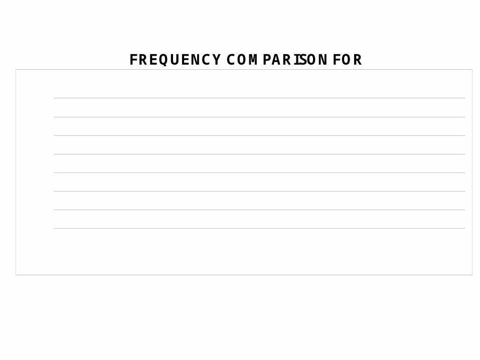
FREQUENCY COMPARISON FOR
47.50
48.00
48.50
49.00
49.50
50.00
50.50
51.00
51.50
00 01 02 03 04 05 06 07 08 09 10 11 12 13 14 15 16 17 18 19 20 21 22 23
04-MARCH 02 & 03
Frequency Variation based on data integrated over ONE minute interval
2003
2002
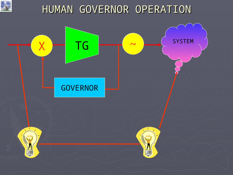
HUMAN GOVERNOR OPERATIONHUMAN GOVERNOR OPERATION
SYSTEM~TGX
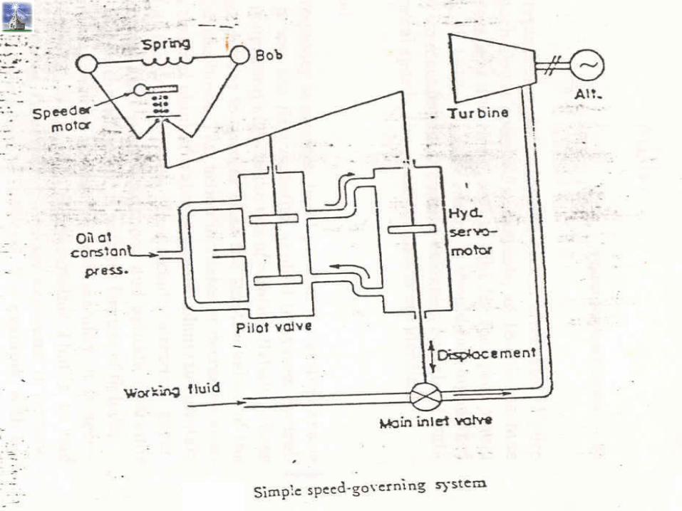
GOVERNOR
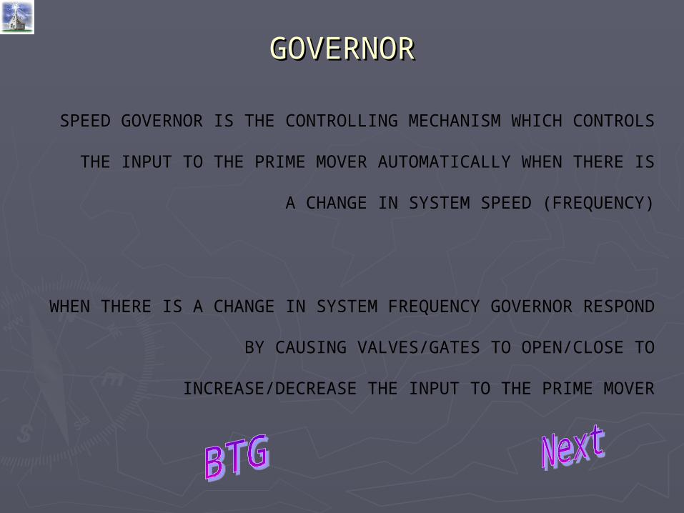
GOVERNORGOVERNOR
SPEED GOVERNOR IS THE CONTROLLING MECHANISM WHICH
CONTROLS THE INPUT TO THE PRIME MOVER AUTOMATICALLY
WHEN THERE IS A CHANGE IN SYSTEM SPEED (FREQUENCY)
WHEN THERE IS A CHANGE IN SYSTEM FREQUENCY GOVERNOR
RESPOND BY CAUSING VALVES/GATES TO OPEN/CLOSE TO
INCREASE/DECREASE THE INPUT TO THE PRIME MOVER
MISCONCEPTIONMISCONCEPTION
Governors attempt to restore frequency to normal.
In reality, Governors attempt to restore load generation balance, using frequency change as a signal.
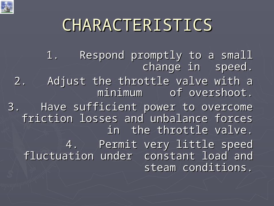
CHARACTERISTICSCHARACTERISTICS
1.1. Respond promptly to a small change Respond promptly to a small change in in speed.speed.
2.2. Adjust the throttle valve with a Adjust the throttle valve with a minimum minimum of overshoot.of overshoot.
3.3. Have sufficient power to overcome Have sufficient power to overcome friction losses and unbalance forces in friction losses and unbalance forces in
the throttle valve.the throttle valve.4.4. Permit very little speed fluctuation Permit very little speed fluctuation
under under constant load and steam constant load and steam conditions.conditions.
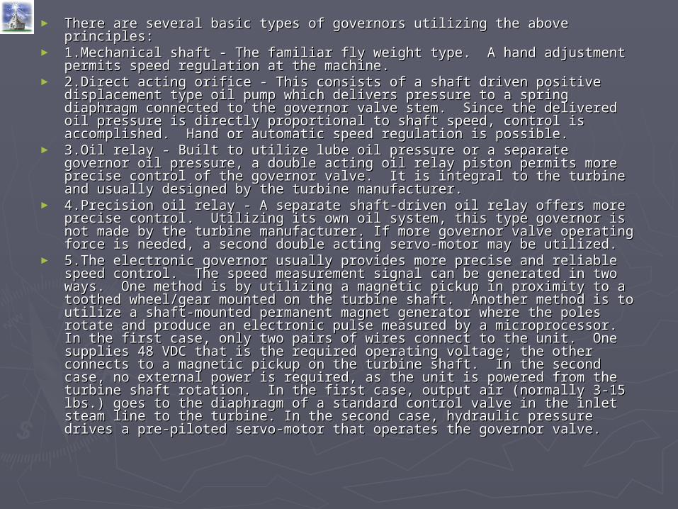
► There are several basic types of governors utilizing the above principles:There are several basic types of governors utilizing the above principles:► 1.Mechanical shaft - The familiar fly weight type. A hand adjustment 1.Mechanical shaft - The familiar fly weight type. A hand adjustment
permits speed regulation at the machine.permits speed regulation at the machine.► 2.Direct acting orifice - This consists of a shaft driven positive displacement 2.Direct acting orifice - This consists of a shaft driven positive displacement
type oil pump which delivers pressure to a spring diaphragm connected to type oil pump which delivers pressure to a spring diaphragm connected to the governor valve stem. Since the delivered oil pressure is directly the governor valve stem. Since the delivered oil pressure is directly proportional to shaft speed, control is accomplished. Hand or automatic proportional to shaft speed, control is accomplished. Hand or automatic speed regulation is possible.speed regulation is possible.
► 3.Oil relay - Built to utilize lube oil pressure or a separate governor oil 3.Oil relay - Built to utilize lube oil pressure or a separate governor oil pressure, a double acting oil relay piston permits more precise control of pressure, a double acting oil relay piston permits more precise control of the governor valve. It is integral to the turbine and usually designed by the the governor valve. It is integral to the turbine and usually designed by the turbine manufacturer.turbine manufacturer.
► 4.Precision oil relay - A separate shaft-driven oil relay offers more precise 4.Precision oil relay - A separate shaft-driven oil relay offers more precise control. Utilizing its own oil system, this type governor is not made by the control. Utilizing its own oil system, this type governor is not made by the turbine manufacturer. If more governor valve operating force is needed, a turbine manufacturer. If more governor valve operating force is needed, a second double acting servo-motor may be utilized.second double acting servo-motor may be utilized.
► 5.The electronic governor usually provides more precise and reliable speed 5.The electronic governor usually provides more precise and reliable speed control. The speed measurement signal can be generated in two ways. control. The speed measurement signal can be generated in two ways. One method is by utilizing a magnetic pickup in proximity to a toothed One method is by utilizing a magnetic pickup in proximity to a toothed wheel/gear mounted on the turbine shaft. Another method is to utilize a wheel/gear mounted on the turbine shaft. Another method is to utilize a shaft-mounted permanent magnet generator where the poles rotate and shaft-mounted permanent magnet generator where the poles rotate and produce an electronic pulse measured by a microprocessor. In the first produce an electronic pulse measured by a microprocessor. In the first case, only two pairs of wires connect to the unit. One supplies 48 VDC that case, only two pairs of wires connect to the unit. One supplies 48 VDC that is the required operating voltage; the other connects to a magnetic pickup is the required operating voltage; the other connects to a magnetic pickup on the turbine shaft. In the second case, no external power is required, as on the turbine shaft. In the second case, no external power is required, as the unit is powered from the turbine shaft rotation. In the first case, output the unit is powered from the turbine shaft rotation. In the first case, output air (normally 3-15 lbs.) goes to the diaphragm of a standard control valve in air (normally 3-15 lbs.) goes to the diaphragm of a standard control valve in the inlet steam line to the turbine. In the second case, hydraulic pressure the inlet steam line to the turbine. In the second case, hydraulic pressure drives a pre-piloted servo-motor that operates the governor valve.drives a pre-piloted servo-motor that operates the governor valve.
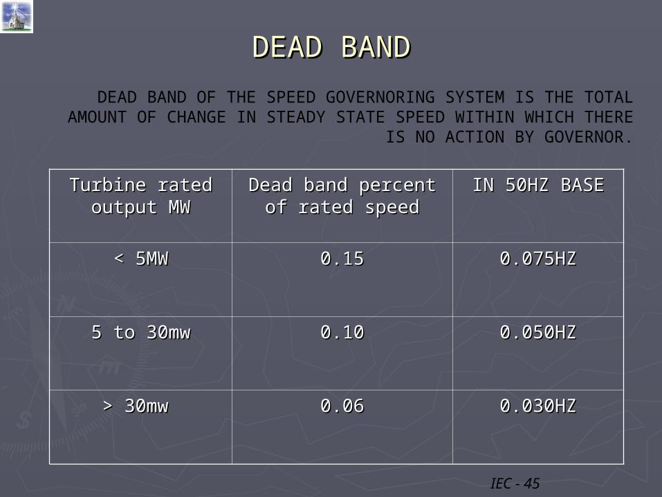
DEAD BANDDEAD BAND
DEAD BAND OF THE SPEED GOVERNORING SYSTEM IS THE TOTAL AMOUNT OF CHANGE IN STEADY STATE SPEED WITHIN WHICH
THERE IS NO ACTION BY GOVERNOR.
Turbine rated Turbine rated output MWoutput MW
Dead band percent of Dead band percent of rated speedrated speed
IN 50HZ BASEIN 50HZ BASE
< 5MW< 5MW 0.150.15 0.075HZ0.075HZ
5 to 30mw5 to 30mw 0.100.10 0.050HZ0.050HZ
> 30mw > 30mw 0.060.06 0.030HZ0.030HZ
IEC - 45

DROOP CHARACTERISTICSDROOP CHARACTERISTICS
THE AMOUNT OF SPEED (OR FREQUENCY) CHANGE THAT IS NECESSARY TO CAUSE THE MAIN PRIME MOVER CONTROL
MECHANISM TO MOVE FROM FULLY CLOSED TO FULLY OPEN.
NORMAL RANGE - 3 TO 5%
THE MINIMUM RATE OF CHANGE OF SPEED SHOULD NOT BE LESS THAN 0.4 TIMES OF ITS DROOP.
THE MAXIMUM RATE OF CHANGE OF SPEED SHOULD NOT BE MORE THAN 3 TIMES OF ITS DROOP.

5% DROOP ON 200MW GENERATOR
0
40
80
120
160
200
49 49.5 50 50.5 51 51.5
FREQ IN HZ --->
GE
NE
RA
TIO
N I
N M
W -
-->

PARTICIPATION OF 5% DROOP ON 200MW & 500MW GENERATORS
0
100
200
300
400
500
600
49 49.5 50 50.5 51 51.5
FREQ IN HZ --->
GE
NE
RA
TIO
N IN
MW
---
>
100MW for 0.5HZ Frequency
40MW for 0.5HZ Frequency
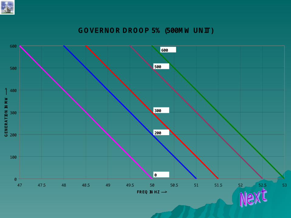
GOVERNOR DROOP 5% (500MW UNIT)
0
100
200
300
400
500
600
47 47.5 48 48.5 49 49.5 50 50.5 51 51.5 52 52.5 53
FREQ IN HZ --->
GE
NE
RA
TIO
N IN
MW
---
->
600
500
300
200
0
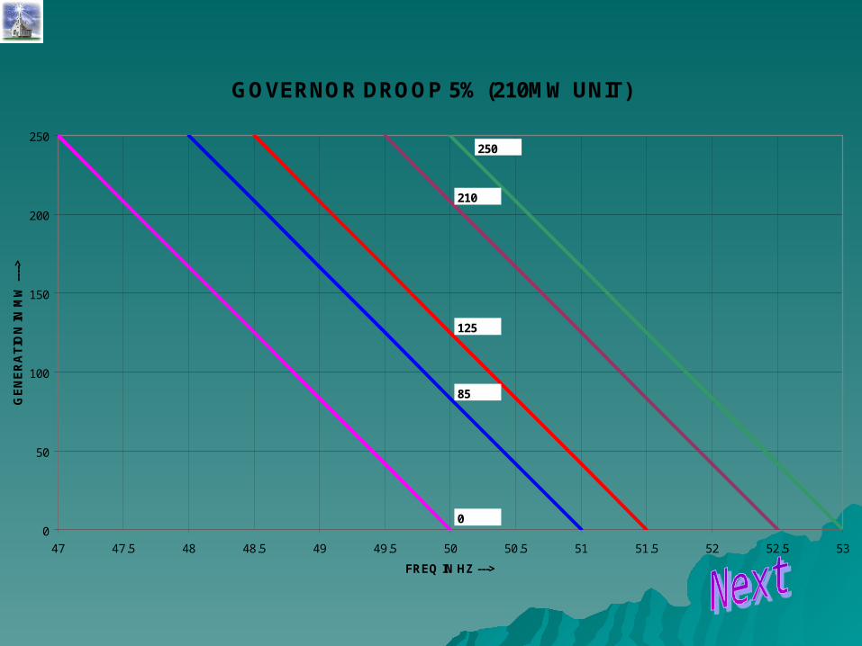
GOVERNOR DROOP 5% (210MW UNIT)
0
50
100
150
200
250
47 47.5 48 48.5 49 49.5 50 50.5 51 51.5 52 52.5 53
FREQ IN HZ --->
GE
NE
RA
TIO
N IN
MW
---
->
250
210
125
85
0
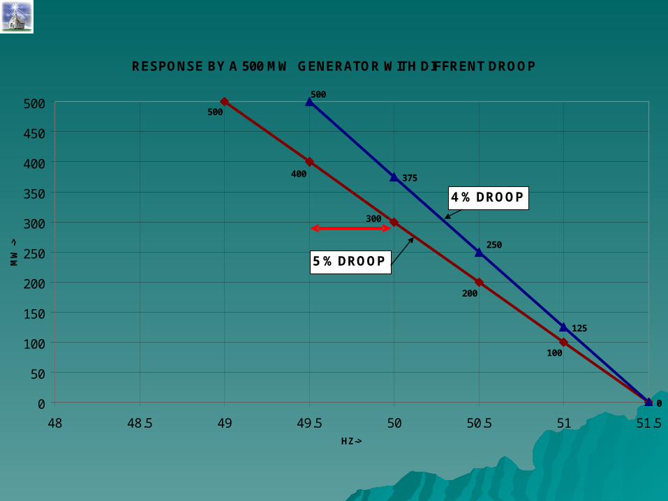
RESPONSE BY A 500 MW GENERATOR WITH DIFFRENT DROOP
0
375
125
0
200
500
400
300
100
500
250
0
50
100
150
200
250
300
350
400
450
500
48 48.5 49 49.5 50 50.5 51 51.5HZ->
MW
->
5 % DROOP
4 % DROOP
GOVERNOR TIME LAGGOVERNOR TIME LAG
TIME TAKEN BY GOVERNOR TO JUST BEGIN CHANGING POWER OUTPUT TO STABILISE FREQUENCY.
OR
TIME BETWEEN A CHANGE IN GENERATOR SPEED & CHANGE IN TURBINE POWER.
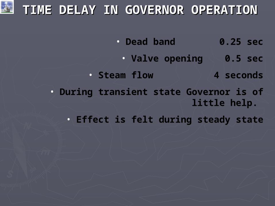
• Dead band 0.25 sec
• Valve opening 0.5 sec
• Steam flow 4 seconds
• During transient state Governor is of little help.
• Effect is felt during steady state
TIME DELAY IN GOVERNOR TIME DELAY IN GOVERNOR OPERATIONOPERATION

BLOCKED GOVERNORBLOCKED GOVERNOR
BYPASSING THE GOVERNING FEEDBACK MECHANISM TO MAINTAIN FIXED GENERATOR OUTPUT.
DISADVANTAGES:-
• SYSTEM INSTABILITY
• RESTORATION OF SYSTEM FREQUENCY TO NORMAL TAKES MORE TIME AFTER A DISTURBANCE.
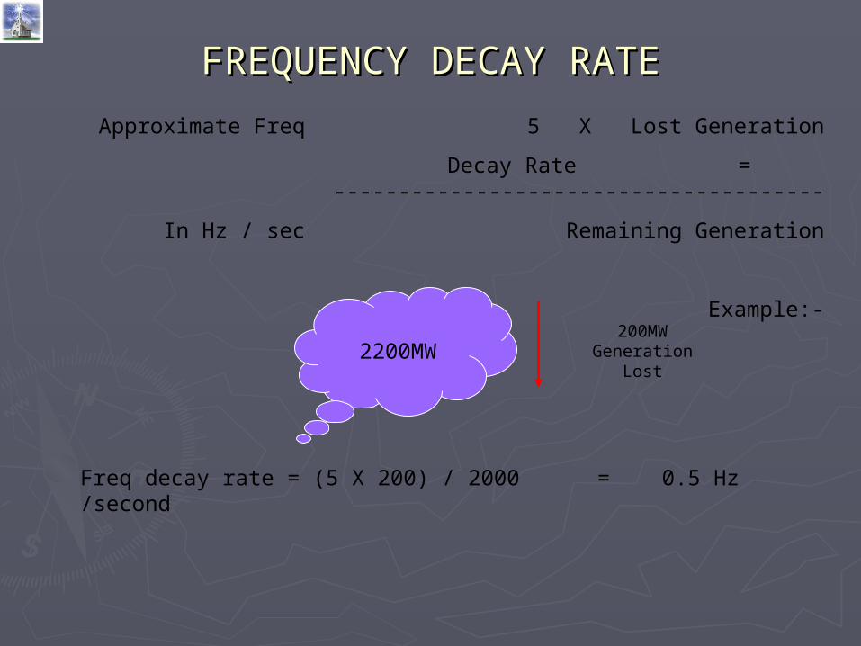
FREQUENCY DECAY RATEFREQUENCY DECAY RATE
Approximate Freq 5 X Lost Generation
Decay Rate = --------------------------------------
In Hz / sec Remaining Generation
Example:-
2200MW200MW
Generation Lost
Freq decay rate = (5 X 200) / 2000 = 0.5 Hz /second
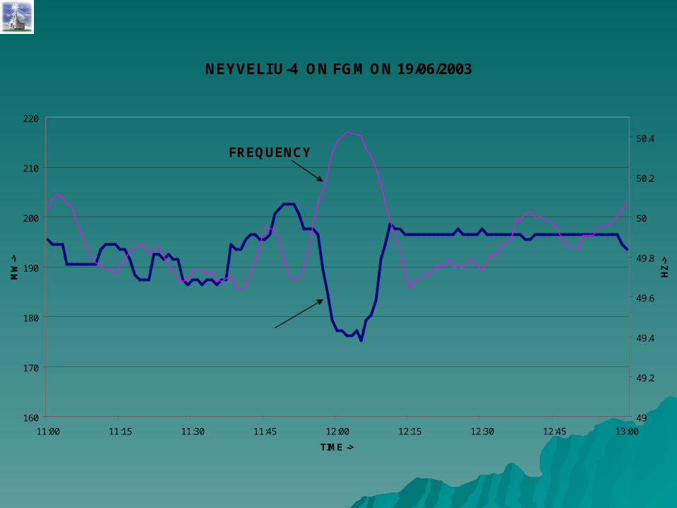
NEYVELI U-4 ON FGM ON 19/06/2003
160
170
180
190
200
210
220
11:00 11:15 11:30 11:45 12:00 12:15 12:30 12:45 13:00
TIME ->
MW
->
49
49.2
49.4
49.6
49.8
50
50.2
50.4
HZ
->
GENERATION
FREQUENCY

DROOP CHARACTERISTICS OF NYL U4
170
175
180
185
190
195
200
205
210
49.6 49.7 49.8 49.9 50 50.1 50.2 50.3 50.4 50.5
FREQ CHANGE 49.7 - > 50.4 0.7HzGEN CHANGE 205 -> 177 35MW CHANGE IN GEN 28 MW FOR 0.7 Hz CHANGE IN FREQFOR 200 MW CHANGE IN GEN FREQ CHANGE REQD =(200*0.7)/28 = 5 Hzi.e 5*100 /50 = 10% Droop
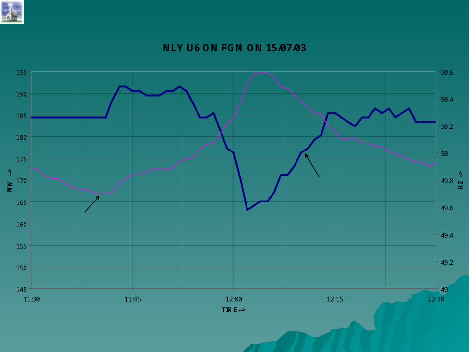
NLY U6 ON FGM ON 15/07/03
145
150
155
160
165
170
175
180
185
190
195
11:30 11:45 12:00 12:15 12:30
TIME-->
MW
-->
49
49.2
49.4
49.6
49.8
50
50.2
50.4
50.6
HZ
-->
GENERATION
FREQUENCY
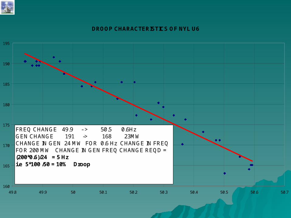
DROOP CHARACTERISTICS OF NYL U6
160
165
170
175
180
185
190
195
49.8 49.9 50 50.1 50.2 50.3 50.4 50.5 50.6 50.7
FREQ CHANGE 49.9 - > 50.5 0.6HzGEN CHANGE 191 -> 168 23MW CHANGE IN GEN 24 MW FOR 0.6 Hz CHANGE IN FREQFOR 200 MW CHANGE IN GEN FREQ CHANGE REQD =(200*0.6)/24 = 5 Hzi.e 5*100 /50 = 10% Droop
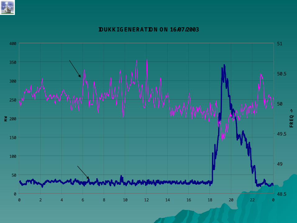
IDUKKI GENERATION ON 16/07/2003
0
50
100
150
200
250
300
350
400
0 2 4 6 8 10 12 14 16 18 20 22 0
MW
48.5
49
49.5
50
50.5
51
FR
EQ
->
FREQUENCY
GENERATION
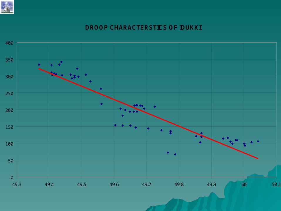
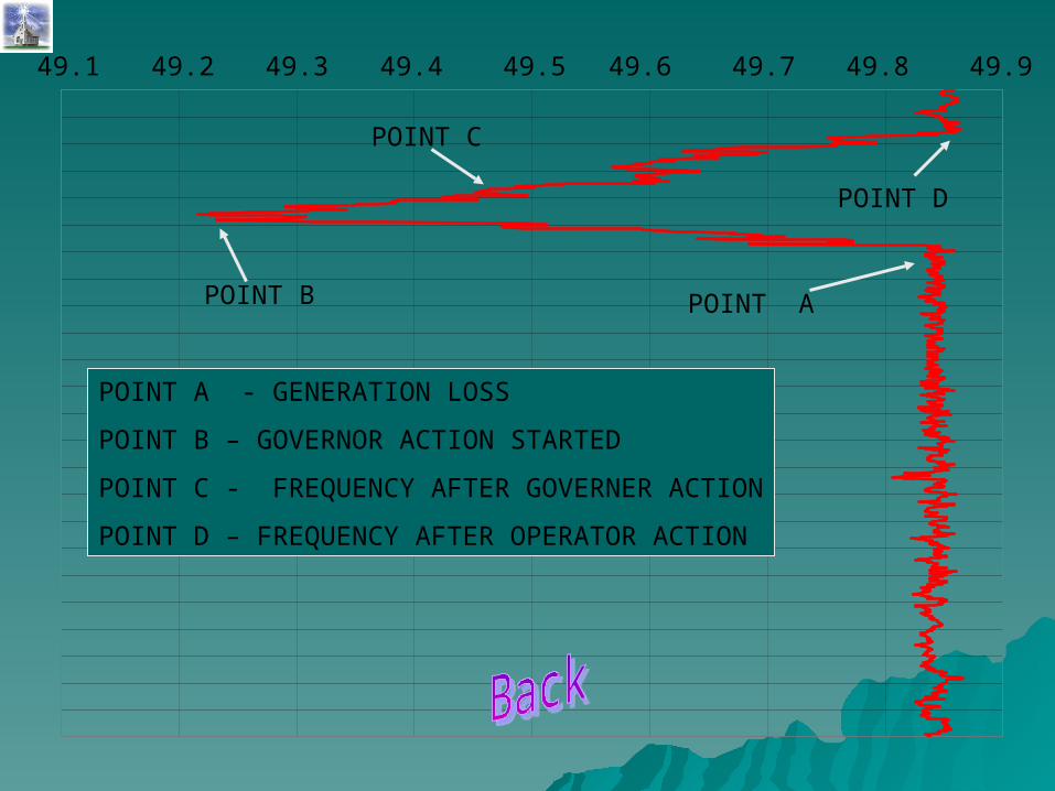
DROOP CHARACTERSTICS OF IDUKKI
0
50
100
150
200
250
300
350
400
49.3 49.4 49.5 49.6 49.7 49.8 49.9 50 50.1
49.849.1 49.749.649.549.449.2 49.3 49.9
POINT APOINT B
POINT C
POINT D
POINT A - GENERATION LOSS
POINT B – GOVERNOR ACTION STARTED
POINT C - FREQUENCY AFTER GOVERNER ACTION
POINT D – FREQUENCY AFTER OPERATOR ACTION

The distance through which one part of connected machinery, as a
wheel, piston, or screw, can be moved without moving the connected parts.
BACKLASHBACKLASH

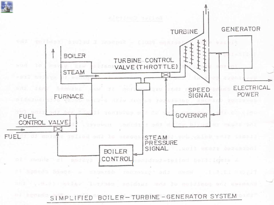
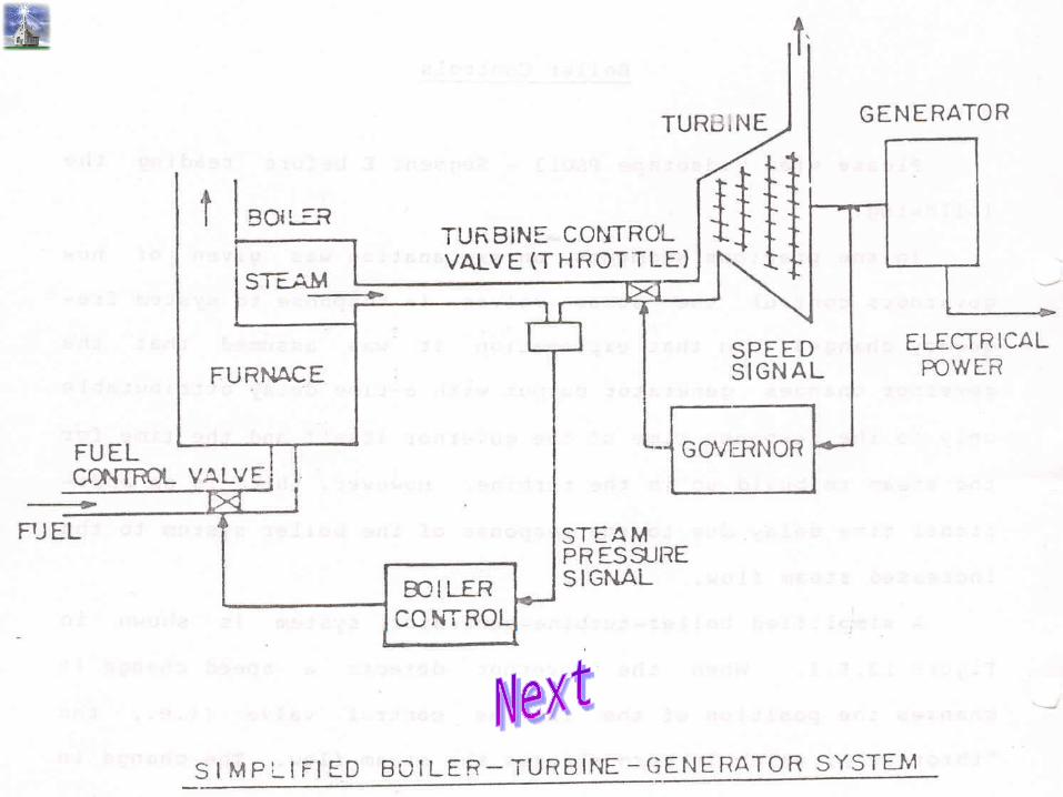
BOILER CONTROLSBOILER CONTROLS
• BOILER FOLLOWING SYSTEM
• TURBINE FOLLOWING SYSTEM
• INTEGRATED CONTROL SYSTEM
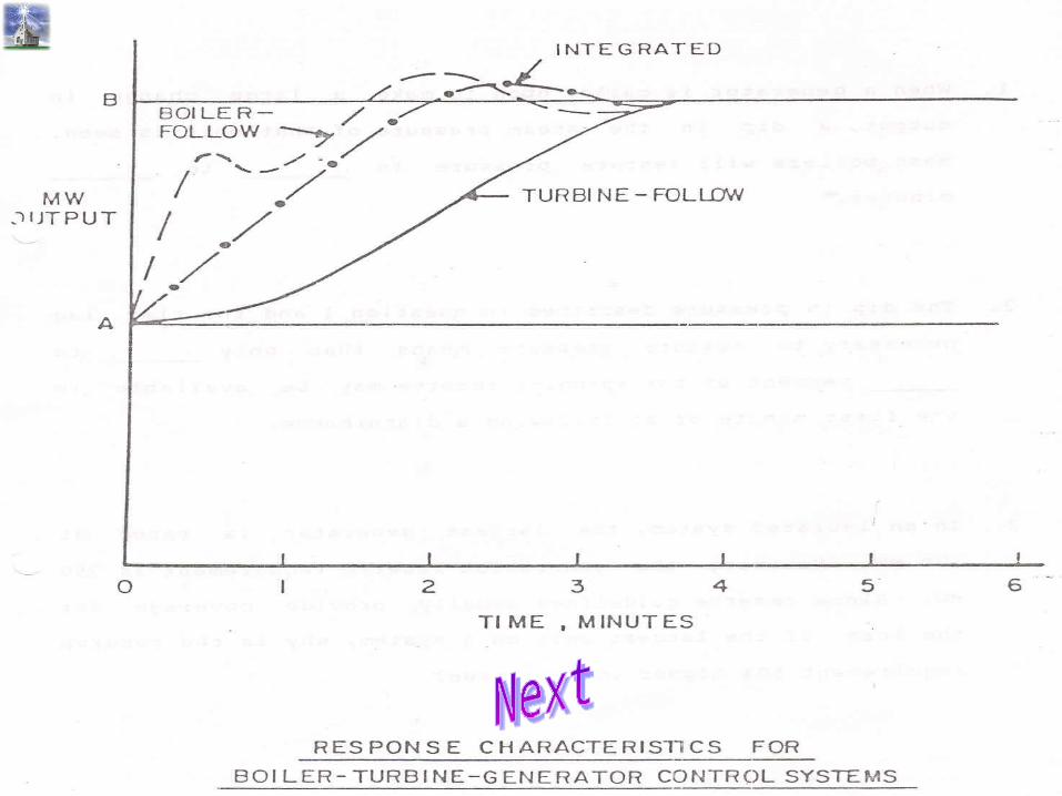
ADVANTAGESADVANTAGES
1. Reduce the random change of frequency
2. Mitigate effect of load generation mismatch
3. Prevents wastage of fuel during low load condition
4. Faster restoration from grid disturbance
PROBLEMSPROBLEMS1.1. Steam deposits on the valve stem (or stems).Steam deposits on the valve stem (or stems).
2.2. Lubrication deposits (i.e., soaps, dirt, detergents, Lubrication deposits (i.e., soaps, dirt, detergents, etc.) in the top works of the valve exposed to the etc.) in the top works of the valve exposed to the
elements.elements.3.3. Mechanical failures of the valve resulting from Mechanical failures of the valve resulting from bent stems, either in the valve proper or the upper bent stems, either in the valve proper or the upper
works, damaged split couplings, etc., all within works, damaged split couplings, etc., all within about a 6" area near the center of the valve about a 6" area near the center of the valve
mechanism.mechanism.4.4. Galling of the piston in the hydraulic latch cylinder.Galling of the piston in the hydraulic latch cylinder.
5.5. Jamming of the screw spindle in the larger Jamming of the screw spindle in the larger cylinder-type valve design due to forcing by cylinder-type valve design due to forcing by
operations personneloperations personnel

FREE GOVERNOR OPERATIONFREE GOVERNOR OPERATION
Mother of all Controls
Self healing mechanism
Collectively Control
Most equitable
Reduces risk of collapse
Makes restoration easy
World wide mandatory practice