power electronics training system add-on to model … power electronics training system – add-on...
TRANSCRIPT

LabVolt Series
Datasheet
Power Electronics Training System – Add-On to Model 8001-1 or 8001-6
Festo Didactic
en 120 V - 60 Hz
05/2018

2 © Festo Didactic
Table of ContentsGeneral Description_______________________________________________________________________2List of Equipment_________________________________________________________________________2List of Manuals___________________________________________________________________________3Table of Contents of the Manual(s) __________________________________________________________3Additional Equipment Required to Perform the Exercises ________________________________________4System Specifications _____________________________________________________________________4Equipment Description ____________________________________________________________________4
General DescriptionThe Power Electronics Training System – Add-On to Model 8001-1 or 8001-6 is an add-on to the 0.2 kW Electromechanical Training Systems, Models 8001-1 or 8001-6, that upgrades either of these systems to a Power Electronics Training System, Model 8010-A. The resulting training system combines a modular design approach with computer-based data acquisition and control to provide unrivaled training in power electronics to students already having a sound knowledge of basic electric power technology. The system features the Four-Quadrant Dynamometer/Power Supply, Model 8960, and the Data Acquisition and Control Interface, Model 9063, two state-of-the-art USB peripherals that greatly enhance the learning experience of students.
Refer to the datasheet for the Power Electronics Training System, Model 8010-A, for more information about the content and features of this training system.
List of Equipment
Qty DescriptionModel number
1 Permanent Magnet DC Motor _____________________________________________________________ 8213-001 Filtering Inductors/Capacitors ____________________________________________________________ 8325-A01 Three-Phase Filter ______________________________________________________________________ 8326-001 Three-Phase Transformer Bank ___________________________________________________________ 8348-401 Lead-Acid Battery Pack __________________________________________________________________ 8802-101 IGBT Chopper/Inverter __________________________________________________________________ 8837-B01 Power Thyristors _______________________________________________________________________ 8841-201 Rectifier and Filtering Capacitors __________________________________________________________ 8842-A01 Connection Lead Set ____________________________________________________________________ 8951-L01 Four-Quadrant Dynamometer/Power Supply ________________________________________________ 8960-E01 Data Acquisition and Control Interface _____________________________________________________ 9063-D0

© Festo Didactic 3
List of Manuals
DescriptionManual number
DC Power Electronics (Student Manual) _______________________________________________________ 86356-00DC Power Electronics (Instructor Guide) _______________________________________________________ 86356-10Single-Phase AC Power Electronics (Student Manual) ____________________________________________ 86359-00Single-Phase AC Power Electronics (Instructor Guide) ____________________________________________ 86359-10Three-Phase AC Power Electronics (Student Manual) ____________________________________________ 86362-00Three-Phase AC Power Electronics (Instructor Guide) ____________________________________________ 86362-10Thyristor Power Electronics (Student Manual) __________________________________________________ 86363-00Thyristor Power Electronics (Instructor Guide) __________________________________________________ 86363-10Three-Phase Motor Drives (Student Manual) ___________________________________________________ 86368-00Three-Phase Motor Drives (Instructor Guide) ___________________________________________________ 86368-10Computer-Based Instruments for EMS (User Guide) _____________________________________________ 86718-E0
Table of Contents of the Manual(s)DC Power Electronics (Student Manual) (86356-00)• 1 The Diode and Switching Transistor• 2 The Buck Chopper• 3 Introduction to High-Speed Power Switching• 4 Ripple in Choppers• 5 The Lead-Acid Battery Charger• 6 The Boost Chopper• 7 The Buck/Boost Chopper• 8 The Four-Quadrant Chopper
Single-Phase AC Power Electronics (Student Manual) (86359-00)• 1 Power Diode Single-Phase Rectifiers• 2 The Single-Phase PWM Inverter
Three-Phase AC Power Electronics (Student Manual) (86362-00)• 1 Power Diode Three-Phase Rectifiers• 2 The Single-Phase PWM Inverter with Dual-Polarity DC Bus• 3 The Three-Phase PWM Inverter
Thyristor Power Electronics (Student Manual) (86363-00)• 1 Power Diode Single-Phase Rectifiers• 2 Power Diode Three-Phase Rectifiers• 3 The Power Thyristor• 4 The Solid State Relay• 5 Single-Phase AC Power Control• 6 Three-Phase AC Power Control• 7 Thyristor Three-Phase Rectifier/Inverter
Three-Phase Motor Drives (Student Manual) (86368-00)• 1 Three-Phase, Variable-Frequency Induction-Motor Drive• 2 Three-Phase, Variable-Frequency Induction-Motor Drive with Constant V/f ratio
Computer-Based Instruments for EMS (User Guide) (86718-E0)

4 © Festo Didactic
1 Optional product training. Price provided on demand. For details and options, contact [email protected] Optional product training. Price provided on demand. For details and options, contact [email protected] Optional product training. Price provided on demand. For details and options, contact [email protected] Optional product training. Price provided on demand. For details and options, contact [email protected] Optional product training. Price provided on demand. For details and options, contact [email protected].
• 1 Familiarization with the Metering Window and the Data Table• 2 Familiarization with the Oscilloscope• 3 Familiarization with the Phasor Analyzer• 4 Familiarization with the Harmonic Analyzer• 5 Measuring Three-Phase Power Using the Metering Window
Additional Equipment Required to Perform the Exercises
Qty DescriptionModel number
1 Training on DC Power Electronics, 0.4 day _________________________________________________ 86356-TF1 Training on Single-Phase AC Power Electronics, 0.2 day ______________________________________ 86359-TF1 Training on Three-Phase AC Power Electronics, 0.2 day _______________________________________ 86362-TF1 Training on Thyristor Power Electronics, 0.5 day ____________________________________________ 86363-TF1 Training on Three-Phase Motor Drives, 0.1 day _____________________________________________ 86368-TF
System SpecificationsParameter Value
Physical Characteristics
Intended Location Installed in the workstation of a 0.2 kW Electromechanical Training Systems, Models 8001-1 or 8001-6
Dimensions (H x W x D) 900 x 930 x 530 mm (35.4 x 36.6 x 20.9 in)
Net Weight TBE
Equipment Description
Permanent Magnet DC Motor 8213-00
The Permanent Magnet DC Motor is a high-speed, brushed dc motor mounted in a full-size EMS module. The magnetic field required for motor operation is produced by powerful permanent magnets mounted on the motor stator. Connections to the motor are made through color-coded safety banana jacks located on the front panel on the module. Power to the motor must be fed by an external dc power source. A toggle switch mounted on the front panel can be
used to switch dc power to the motor on and off when the motor is connected to a battery pack. When driven by a prime mover, the Permanent Magnet DC Motor operates as a dc generator.
The front panel of the Permanent Magnet DC Motor module can be opened to install a Timing Belt, Model 8942, on the pulley of the motor shaft. This permits mechanical coupling of this motor to the Four-Quadrant
1
2
3
4
5

© Festo Didactic 5
Dynamometer/Power Supply, Model 8960. The diameter of the Permanent Magnet DC Motor pulley is smaller (12 teeth) than that of the pulleys of the Four-Quadrant Dynamometer/Power Supply (24 teeth). This difference of pulley ratio (12 to 24) permits adapting the speed (0 4000 r/min) of the Permanent Magnet DC Motor to the speed of the Four-Quadrant Dynamometer/Power Supply (between 0 2000 r/min).
SpecificationsParameter Value
Nominal Characteristics
Power 220 W
Voltage 48 V
Current 6.7 A
Speed 4000 r/min
Torque 0.53 N·m (4.6 lbf·in)
Duty Cycle 15 min ON / 60 min OFF
Pulley
Number of teeth 12
Physical Characteristics
Dimensions (H x W x D) 308 x 291 x 440 mm (2.1 x 11.5 x 17.3 in)
Net Weight 7.6 kg (16.8 lb)
Filtering Inductors/Capacitors 8325-A0
This Filtering Inductors/Capacitors module consists of two separate filters enclosed in a half-size EMS module: a low-frequency filter and a high-frequency filter. The low-frequency filter consists of an inductor and a polarized capacitor, while the high-frequency filter consists of two inductors and a non-polarized capacitor. Internal electrical components are identified on the
module front panel. 4 mm banana jacks provide access to the different components in the module.
SpecificationsParameter Value
Low Frequency Filter
Inductance 50 mH - 5 A - 0-2 kHz
Capacitor (Aluminium Electrolytic) 210 µF - 450 V
High Frequency Filter
Inductance (2) 2 mH - 5 A - 0-20 kHz
Capacitor (Metallized Polypropylene) 5 µF - 400 V
Supplementary Capacitor (Met. Prop.) N/A
Physical Characteristics
Dimensions (H x W x D) 154 x 287 x 440 mm (6.1 x 11.3 x 17.3 in)
Net Weight 12.3 kg (27.12 lb)

6 © Festo Didactic
Three-Phase Filter 8326-00
The Three-Phase Filters consists of three inductors and four capacitors enclosed in a half-size EMS module. Eight safety banana jacks on the module front panel provide access to the three-phase filter. The module is used to filter three-phase signals in power electronics applications.
SpecificationsParameter Value
Inductors
Number 3
Ratings 2 mH – 5 A – 0-20 kHz
Capacitors
Number 4
Type Metallized polypropylene
Ratings 5 µF – 400 V
Physical Characteristics
Dimensions (H x W x D) 154 x 287 x 440 mm (6.1 x 11.3 x 17.3 in)
Net Weight TBE
Three-Phase Transformer Bank 8348-40
The Three-Phase Transformer Bank consists of three independent power transformers enclosed in a module. Safety banana jacks on the module front panel provide individual access to the windings of each power transformer, allowing connection in either wye or delta configuration. The transformer windings are polarized and the polarity of each winding is
indicated by a small dot on the module front panel. Resettable fuses protect the primary and secondary windings of each transformer against overcurrents. Fuse status lamps on the module front panel turn on when the resettable fuses open.
SpecificationsParameter Value
Rating (Each Transformer)
Primary Voltage 208 V
Secondary Voltage 208/120 V
Power 250 VA
Full-Load Current 1.2 A
Physical Characteristics
Dimensions (H x W x D) 154 x 287 x 410 mm (6.1 x 11.3 x 16.1 in)
Net Weight 13.9 kg (30.6 lb)

© Festo Didactic 7
Lead-Acid Battery Pack 8802-10
The Lead-Acid Battery Pack is a half-size EMS module housing four 12 V lead-acid batteries connected in series. The Lead-Acid Battery Pack thus provides a fixed dc voltage of 48 V, available at two color-coded safety banana jacks on the module front panel. Three battery voltage test points allow measurement of the voltage provided by each of the four
12 V batteries. A parallel charging input terminal permits the charging of several Lead Acid Battery Packs connected in parallel at the same time. The Lead-Acid Battery Pack is protected against overcurrents and short-circuits. The Lead-Acid Battery Pack can be used as a 48 V dc power source, and in energy production and storage applications implemented with the Electricity and New Energy Training Equipment.
SpecificationsParameter Value
Battery Pack
Type 4 valve-regulated lead-acid batteries
Voltage 48 V (12 V for each battery)
Capacity 9 Ah
Maximum Charge Current 2.7 A
Maximum Discharge Current 7 A
Parallel Charging Input 58 V maximum
Overcurrent Protection
Battery Pack Fuse 10 A
Test Point Limiting Resistors (3) 1 kΩ
Physical Characteristics
Dimensions (H x W x D) 154 x 287 x 440 mm (6.1 x 11.3 x 17.3 in)
Net Weight TBE
IGBT Chopper/Inverter 8837-B0
The IGBT Chopper/Inverter module consists of seven insulated-gate bipolar transistors (IGBT) mounted in a half-size EMS module. Six IGBTs are used to implement choppers and inverters. These IGBTs are protected against a variety of abnormal operating conditions, such as short-circuits, overvoltage, overcurrent, and
overheat. The seventh IGBT and a dumping resistor allow smooth dissipation of excess energy at the dc bus. The dumping circuit can be activated through the use of a toggle switch on the front panel.
The module switching control section allows 0/5 V pulse signals from either the Data Acquisition and Control Interface, Model 9063, the Chopper/Inverter Control Unit, Model 9029, or any compatible 0/5 V control unit, to be applied to the gating circuits of the IGBTs. The signals are input in the IGBT Chopper/Inverter module through a nine-pin connector.

8 © Festo Didactic
Six miniature banana jacks can be used as test points to monitor the pulse signals using an oscilloscope. These jacks can also be used to inject 0/5 V pulse signals from an alternate control unit, as well as to inhibit each gating circuit. The IGBT Chopper/Inverter module also includes a synchronization output to trigger an oscilloscope when observing the switching control signals, as well as a switching control disable input that allows all six IGBTs in the chopper/inverter section to be switched off.
SpecificationsParameter Value
DC Bus
Maximum Voltage 420 V
Maximum Current 6 A
Filtering Capacitor 1360 µF
Protections
DC Bus Overvoltage 440 V
DC Bus Circuit Breaker 6 A
IGBT Electronic Overcurrent 12 A
IGBT Overheat About 70°C
Dumping Circuit
Voltage Threshold 330 V
Resistor 100 Ω, 100 W
Switching Control Signals
Level 0/5 V
Frequency Range 0-20 kHz
Minimum Dead Time 700 ns
Power Requirements 24 V, 0.16 A, 50/60 Hz
Accessories
Accessories 24 V power cable (1)
2 mm banana plug test leads (2)
Physical Characteristics
Dimensions (H x W x D) 154 x 287 x 410 mm (6.1 x 11.3 x 16.1 in)
Net Weight 5.67 kg (12.5 lb)
Power Thyristors 8841-20
The Power Thyristors module consists of six power thyristors (SCRs) mounted in a half-size EMS enclosure. Each individual thyristor is protected against overcurrents and short-circuits. All the anodes and cathodes of the thyristors are terminated on the front panel by color-coded, 4 mm safety banana jacks. To reduce the
number of external connections, the most typical thyristor configurations can be achieved through the use of two toggle switches on the front panel.
A firing control section allows six 0-5 V pulse signals from either the Data Acquisition and Control Interface, Model 9063, the Thyristor Firing Unit, Model 9030, or any compatible 0-5 V control unit, to be applied to the gating circuits of the thyristors. The signals are input in the Power Thyristors module through a nine-pin connector.
Six miniature banana jacks in this section are used as test points to monitor the firing control signals using an oscilloscope. They can also be used to inject 0-5 V pulse signals from an alternate firing unit, as well as to inhibit each gating circuit. The Power Thyristors module also includes a synchronization output to trigger an

© Festo Didactic 9
oscilloscope when observing the firing control signals as well as a firing control disable input that prevents all six power thyristors from being fired.
SpecificationsParameter Value
Rating
Peak Inverse Voltage 600 V
Maximum Current 2 A
Gate Control Signals 0-5 V Pulses (TTL compatible)
Physical Characteristics
Dimensions (H x W x D) 154 x 287 x 440 mm (6.1 x 11.3 x 17.3 in)
Net Weight 5.6 kg (12.35 lb)
Rectifier and Filtering Capacitors 8842-A0
This Rectifier and Filtering Capacitors module consists of a three-phase bridge rectifier and two separate capacitors enclosed in a half-size EMS module. The bridge allows the conversion of a three-phase voltage input into an unfiltered dc voltage. This dc voltage can then be filtered using the polarized capacitors (each one protected by a diode). Internal
electrical components are identified on the module front panel by silkscreened symbols and terminated by 4 mm safety banana jacks.
SpecificationsParameter Value
Electrical Characteristics
Maximum Network Voltage 230 V - 3~ - 50/60 Hz
Maximum Diode Current 8 A
Each Capacitor 210 µF - 450 V dc
Physical Characteristics
Dimensions (H x W x D) 154 x 287 x 440 mm (6.1 x 11.3 x 17.3 in)
Net Weight 2.9 kg (6.4 lb)
Connection Lead Set 8951-L0This Connection Lead Set consists of extra-flexible leads terminated with stacking 4 mm safety banana plugs. In addition, the set includes stacking 2 mm banana plug leads of the same length and color.
SpecificationsParameter Value
4 mm Safety Banana Plug Leads Characteristics
Cross Section 1 mm² (1974 cmil)
Rated Current 19 A
Rated Voltage 600 V, CAT II
4 mm Safety Banana Plug Leads Quantities
Yellow, 30 cm (12 in) 20
Red, 60 cm (24 in) 10
Blue, 90 cm (36 in) 4

10 © Festo Didactic
Parameter Value
2 mm Safety Banana Plug Leads Characteristics
Cross Section 0.5 mm² (987 cmils)
Rated Current 10 A
Rated Voltage 30 V ac / 60 V dc
2 mm Safety Banana Plug Leads Quantities
Red, 60 cm (24 in) 4
Four-Quadrant Dynamometer/Power Supply 8960-E0
The Four-Quadrant Dynamometer/Power Supply is a highly versatile USB peripheral designed to be used in the Electric Power Technology Training Systems. Two operating modes are available: Dynamometer and Power Supply. A wide variety of user-selectable functions is available in each operating mode.
In the Dynamometer mode, the unit becomes a four-quadrant dynamometer that can act as either a
fully configurable brake (i.e., a mechanical load) or a fully configurable prime mover (i.e., a motor drive). In the Power Supply mode, the unit becomes a four-quadrant power supply that can act as a dc voltage source, dc current source, ac power source, etc.
In each operating mode, key parameters related to the selected function are displayed. Speed, torque, mechanical power, and energy are displayed in the Dynamometer mode while voltage, current, electrical power, and energy are displayed in the Power Supply mode. Optional functions, such as a small wind-turbine emulator, a hydraulic turbine emulator, a solar panel emulator, battery chargers, an SDK (Software Development Kit) etc., can be added to the standard functions to further enhance the training possibilities of the Four-Quadrant Dynamometer/Power Supply.
Two modes are available to control the function which the Four-Quadrant Dynamometer/Power Supply performs: Manual and Computer-Based.
In the Manual control mode, the module operates as a stand-alone unit, and the function performed is selected, set, and monitored using front-panel mounted controls and display. This mode provides access to all basic functions. In the Computer-Based control mode, the function performed by the module is selected, set, and monitored using the LVDAC-EMS software. In this mode, communication between the Four-Quadrant Dynamometer/Power Supply and the host computer running the LVDAC-EMS software is achieved through a USB connection. This mode provides access to all basic functions, as well as to additional advanced functions.
Model 8960-E includes the Four-Quadrant Dynamometer/Power Supply, Model 8960-2, with the following function sets activated:
• Standard Functions (Manual Control), Model 8968-1• Standard Functions (Computer-Based Control), Model 8968-2• Lead-Acid Battery Charger, Model 8968-4
Additional Equipment Required to Perform the Exercises

© Festo Didactic 11
6 Refer to the Computer Requirements in the System Specifications section of this datasheet if the computer is to be provided by the end-user. Note that only one computer is required per station.
Qty DescriptionModel number
1 Personal Computer _____________________________________________________________________ 8990-00
SpecificationsParameter Value
Dynamometer Mode
Magnetic Torque 0 to 3 N·m (0 to 27 lbf·in)
Direction of Rotation CW / CCW
Speed 0 to 2500 r/min
Nominal Power 350 W
Power Supply Mode
DC Voltage 0 to ± 150 V
AC Voltage (RMS) 0 to 105 V (no-load)
DC Current 0 to ± 5 A
AC Current (RMS) 0 to 3.5 A
Maximum Output Power 500 W
AC Frequency 10 to 120 Hz
Control Functions
Activated Sets Standard Functions (Manual Control), Model 8968-1
Standard Functions (Computer-Based Control), Model 8968-2
Lead-Acid Battery Charger, Model 8968-4
Liquid-Crystal Display (LCD) 76 mm (3 in), monochrome, background-illuminated, 240 x 160 dots
Control Inputs
Command Input 0 to ± 10 V
Thermistor Input 10 kΩ, type 1
Control Outputs
Shaft Encoder Quadrature encoder (A-B) - 360 pulses/revolution - TTL compatible
Torque Output Sensitivity 0.3 N·m/V (2.655 lbf·in/V)
Speed Output Sensitivity 500 r/min/V
Communication Port USB 2.0
Power Requirements 120 V - 6 A - 60 Hz, must include live, neutral, and ground wires
Computer RequirementsA currently available personal computer with USB 2.0 ports, running under one of the following operating
systems: Windows® 7 or Windows® 8.
Physical Characteristics
Dimensions (H x W x D) 308 x 287 x 490 mm (12.1 x 11.3 x 19.3 in)
Net Weight 19.5 kg (43.0 lb)
Standard Functions (manual control) Set 8968-10The Standard Functions (manual control) Set is a package of control functions that can be activated in the Four-Quadrant Dynamometer/Power Supply, Model 8960-2, enabling the module to perform a wide variety of functions in each of its two operating modes (Dynamometer and Power Supply).
The set allows only manual control of the functions. This means that the Four-Quadrant Dynamometer/Power Supply operates as a stand-alone unit, and the function performed is selected, set, and monitored using front-panel mounted controls and display. The following control functions are available in the set:
Dynamometer operating mode
• Two-Quadrant, Constant-Torque Brake• Clockwise Prime Mover/Brake• Counterclockwise Prime Mover/Brake• Clockwise Constant-Speed Prime Mover/Brake
6

12 © Festo Didactic
• Counterclockwise Constant-Speed Prime Mover/Brake• Positive Constant-Torque Prime Mover/Brake• Negative Constant-Torque Prime Mover/Brake
Power Supply operating mode
• Positive Voltage Source• Negative Voltage Source• 200 V DC Bus• Positive Current Source• Negative Current Source• 50 Hz Power Source• 60 Hz Power Source• Lead-Acid Battery Float Charger
SpecificationsParameter Value
Control Functions
Control Functions Two-Quadrant, Constant-Torque Brake
Clockwise Prime Mover/Brake
Counterclockwise Prime Mover/Brake
Clockwise Constant-Speed Prime Mover/Brake
Counterclockwise Constant-Speed Prime Mover/Brake
Positive Constant-Torque Prime Mover/Brake
Negative Constant-Torque Prime Mover/Brake
Positive Voltage Source
Negative Voltage Source
Positive Current Source
Negative Current Source
50 Hz Power Source
60 Hz Power Source
200 V DC Bus
Lead-Acid Battery Float Charger
Two-Quadrant, Constant-Torque Brake
Torque 0-3 N·m (26.55 lbf·in)
Clockwise/Counterclockwise Prime Mover/Brake
Speed 0-2500 r/min
Clockwise/Counterclockwise Constant-Speed Prime Mover/Brake
Speed 0-2500 r/min
Positive/Negative Constant-Torque Prime Mover/Brake
Torque 0-3 N·m (26.55 lbf·in)
Positive/Negative Voltage Source
Voltage 0 to ±150 V
Positive/Negative Current Source
Current 0 to ±5 A
50 Hz/60 Hz Power Source
No-Load Voltage 0-140 V
200 V DC Bus
Status On or off
Lead-Acid Battery Float Charger
Float Voltage 0-150 V
© Festo Didactic 13
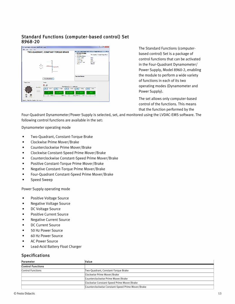
Standard Functions (computer-based control) Set 8968-20
The Standard Functions (computer-based control) Set is a package of control functions that can be activated in the Four-Quadrant Dynamometer/Power Supply, Model 8960-2, enabling the module to perform a wide variety of functions in each of its two operating modes (Dynamometer and Power Supply).
The set allows only computer-based control of the functions. This means that the function performed by the
Four-Quadrant Dynamometer/Power Supply is selected, set, and monitored using the LVDAC-EMS software. The following control functions are available in the set:
Dynamometer operating mode
• Two-Quadrant, Constant-Torque Brake• Clockwise Prime Mover/Brake• Counterclockwise Prime Mover/Brake• Clockwise Constant-Speed Prime Mover/Brake• Counterclockwise Constant-Speed Prime Mover/Brake• Positive Constant-Torque Prime Mover/Brake• Negative Constant-Torque Prime Mover/Brake• Four-Quadrant Constant-Speed Prime Mover/Brake• Speed Sweep
Power Supply operating mode
• Positive Voltage Source• Negative Voltage Source• DC Voltage Source• Positive Current Source• Negative Current Source• DC Current Source• 50 Hz Power Source• 60 Hz Power Source• AC Power Source• Lead-Acid Battery Float Charger
SpecificationsParameter Value
Control Functions
Control Functions Two-Quadrant, Constant-Torque Brake
Clockwise Prime Mover/Brake
Counterclockwise Prime Mover/Brake
Clockwise Constant-Speed Prime Mover/Brake
Counterclockwise Constant-Speed Prime Mover/Brake

14 © Festo Didactic
Parameter Value
Positive Constant-Torque Prime Mover/Brake
Negative Constant-Torque Prime Mover/Brake
Four-Quadrant, Constant-Speed Prime Mover/Brake
Speed Sweep
Mechanical Load
Positive Voltage Source
Negative Voltage Source
DC Voltage Source
Positive Current Source
Negative Current Source
DC Current Source
50 Hz Power Source
60 Hz Power Source
AC Power Source
Lead-Acid Battery Float Charger
Two-Quadrant, Constant-Torque Brake
Torque Control Software knob, 8960 module knob, or 8960 command input
Torque 0-3 N·m (26.55 lbf·in)
Pulley Ratio 24:24, 24:12, or 24:32
Clockwise/Counterclockwise Prime Mover/Brake
Speed Control Software knob, 8960 module knob, or 8960 command input
Speed 0-2500 r/min
Pulley Ratio 24:24, 24:12, or 24:32
Clockwise/Counterclockwise Constant-Speed Prime Mover/Brake
Speed Control Software knob, 8960 module knob, or 8960 command input
Speed 0-2500 r/min
Pulley Ratio 24:24, 24:12, or 24:32
Positive/Negative Constant-Torque Prime Mover/Brake
Torque Control Software knob, 8960 module knob, or 8960 command input
Torque 0-3 N·m (26.55 lbf·in)
Pulley Ratio 24:24, 24:12, or 24:32
Four-Quadrant, Constant-Speed Prime Mover/Brake
Speed Control Software knob, 8960 module knob, or 8960 command input
Speed 0-2500 r/min
Pulley Ratio 24:24, 24:12, or 24:32
Speed Sweep
Start Speed -3000 r/min to 3000 r/min
Finish Speed -3000 r/min to 3000 r/min
Number of Steps 0-50 steps
Step Duration 2-10 s
Record Data to Table Yes or no
Pulley Ratio 24:24, 24:12, or 24:32
Mechanical Load
Load Type Flywheel, fan, grinder, conveyor, calender, crane, user defined
Inertia 0.005-1 kg·m² (0.119-23.73 lb·ft²)
Friction Torque 0.05-3 N·m (0.44-26.55 lbf·in)
Pulley Ratio 24:24, 24:12, or 24:32
Positive/Negative Voltage Source
Voltage Control Software knob, 8960 module knob, or 8960 command input
Voltage 0 V to 147 V / -147 V to 0 V
DC Voltage Source
Voltage Control Software knob, 8960 module knob, or 8960 command input
Voltage -147 V to 147 V
Positive/Negative Current Source
Current Control Software knob, 8960 module knob, or 8960 command input
Current 0 A to 5 A / -5 A to 0 A
DC Current Source
Current Control Software knob, 8960 module knob, or 8960 command input

© Festo Didactic 15
Parameter Value
Current -5 A to 5 A
50 Hz/60 Hz Power Source
Voltage Control Software knob, 8960 module knob, or 8960 command input
No-Load Voltage 0-140 V
AC Power Source
No-Load Voltage 0-140 V
DC Offset Correction -1000 to 1000
Frequency 10-100 Hz
Lead-Acid Battery Float Charger
Float Voltage 0-150 V
Lead-Acid Battery Charger Function Set 8968-40
The Lead-Acid Battery Charger Function Set is a package of control functions that can be activated in the Four-Quadrant Dynamometer/Power Supply, Model 8960-2, enabling the module to implement a lead-acid battery charger, as well as a battery discharger.
The Lead-Acid Battery Charger control function is only available in computer-based mode. This means that the function performed by the Four-
Quadrant Dynamometer/Power Supply is selected, set, and monitored using the LVDAC-EMS software. The following control functions are available in the set:
Power Supply operating mode
• Lead-Acid Battery Charger (Fast):
This function uses the four-quadrant power supply to implement a battery charger that is able to rapidly charge lead-acid batteries of various capacities (typically in less than two hours). A three-step charge algorithm is used. Battery charging starts with a constant current corresponding to the battery maximum charge current until the battery gassing voltage is reached. At this point, battery charging continues with a constant voltage (close to gassing voltage) until the charge current decreases to 0.1 C. Then, constant-voltage charging continues but at a lower voltage (float charging voltage). The user has to specify the following four battery characteristics for the charger to achieve proper charge control: maximum charge current, gassing voltage, 0.1C current (10% of battery capacity), and float charging voltage. The function indicates the voltage, current, electrical power, and energy at the charger output. The function can also indicate battery temperature when the temperature sensor of the battery (if so equipped) is connected to the Thermistor Input of the Four-Quadrant Dynamometer/Power Supply. The function can also indicate battery temperature when the temperature sensor of the battery (if so equipped) is connected to the Thermistor Input of the Four-Quadrant Dynamometer/Power Supply. The license for the Lead-Acid Battery Charger, Model 8968-4, is required to activate the Lead-Acid Battery Charger (Fast) function in the Four-Quadrant Dynamometer/Power Supply.
• Battery Discharger (Constant-Current Timed Discharge with Voltage Cutoff):

16 © Festo Didactic
This function uses the four-quadrant power supply to sink a constant current from a battery, thereby discharging the battery at a specific rate, during a specific period. The discharger also monitors the battery voltage during discharge. Battery discharging terminates immediately when the battery voltage decreases to a specific cutoff voltage. The user has to specify the discharge current, discharge duration, and cutoff voltage for the discharger to achieve proper discharge control. The function indicates the voltage, current, electrical power, and energy at the discharger output. The function can also indicate battery temperature when the temperature sensor of the battery (if so equipped) is connected to the Thermistor Input of the Four-Quadrant Dynamometer/Power Supply. The Battery Discharger function is perfectly suited to measure discharge characteristics of batteries at various rates as well as to bring a battery to a specific depth of discharge before a battery charging experiment. The license for the Lead-Acid Battery Charger, Model 8968-4, or the license for the Ni-MH Battery Chargers, Model 8968-5, is required to activate the Battery Discharger (Contant-Current Timed Discharge with Voltage Cutoff) function in the Four-Quadrant Dynamometer/Power Supply.
SpecificationsParameter Value
Control Functions
Control Functions Lead-Acid Battery Charger (Fast)
Battery Discharger (Constant-Current Timed Discharge with Voltage Cutoff)
Lead-Acid Battery Charger (Fast)
Maximum Charge Current 0-5 A
Gassing Voltage 0-150 V
0.1C Current 0-5 A
Float Voltage 0-150 V
Battery Discharger (Constant-Current Timed Discharge with Voltage Cutoff)
Discharge Current 0-5 A
Discharge Duration 0-2000 min
Cutoff Voltage 0-150 V
Data Acquisition and Control Interface 9063-D0
The Data Acquisition and Control Interface (DACI) is a versatile USB peripheral used for measuring, observing, analyzing, and controlling electrical and mechanical parameters in electric power systems and power electronics circuits. For these purposes, a set of computer-based instruments as well as a variety of control functions are available for the DACI. These instruments and control functions are accessed through the
LVDAC-EMS software. The LVDAC-EMS software, as well as all available upgrades, is free and can be downloaded anytime on the Festo Didactic website.
Together, the DACI and the LVDAC-EMS software allow training in various areas such as electric power technology, ac/dc machines, renewable energy, transmission lines, and power electronics using modern and versatile measuring instruments and control functions. LVDAC-EMS also offers the possibility to use pre-built SCADA interfaces for several applications to ease the view and understanding of the process taking place. The

© Festo Didactic 17
7 Refer to the Computer Requirements in the System Specifications section of this datasheet if the computer is to be provided by the end-user. Only one computer is required per station. This model is available in multiple voltage- and frequency dependent variants. Contact a Festo representative to
obtain the correct part number.8 Required if power is not supplied by the Power Supply, Model 8821-2. This model is available in multiple voltage- and frequency dependent variants. Contact a Festo representative to obtain the correct part number.
user guide provided allows students to quickly become familiar with the instruments and control functions available.
Model 9063-D includes the DACI, Model 9063, with the following function sets activated:
• Computer-Based Instrumentation Function, Model 9069-1• Chopper/Inverter Control Function Set, Model 9069-2• Thyristor Control Function Set, Model 9069-3
Manual
DescriptionManual number
Computer-Based Instruments for EMS (User Guide) _____________________________________________ 86718-E0
Table of Contents of the Manual(s)
Computer-Based Instruments for EMS (User Guide) (86718-E0)• 1 Familiarization with the Metering Window and the Data Table• 2 Familiarization with the Oscilloscope• 3 Familiarization with the Phasor Analyzer• 4 Familiarization with the Harmonic Analyzer• 5 Measuring Three-Phase Power Using the Metering Window
Additional Equipment Required to Perform the Exercises
Qty DescriptionModel number
1 Personal Computer _____________________________________________________________________ 8990-001 24 V AC Power Supply _________________________________________________________________ 30004-20
SpecificationsParameter Value
Insulated Voltage Inputs (4)
Range (Low / High Scales) -80 to +80 V / -800 to + 800 V (user-selectable through software)
Impedance (Low / High Scales) 326.6 kΩ / 3.25 MΩ
Bandwidth DC to 65 kHz (-3 dB)
Accuracy 1% (dc to 10 kHz)
Insulation 800 V
Measurement Category CAT II (283 V ac/400 V dc versus ground)
Insulated Current Inputs (4)
Range (Low / High Scales) -4 to +4 A / -40 to + 40 A (25 A rms)
Impedance (Low / High Scales) 5 mΩ / 50 mΩ
Bandwidth DC to 65 kHz (-3 dB)
Accuracy 1% (dc to 10 kHz)
Insulation 800 V
Measurement Category CAT II (283 V ac/400 V dc versus ground)
Analog Inputs (8)
Voltage Range -10 to +10 V
Impedance > 10 MΩ
Bandwidth DC to 125 kHz
7
8

18 © Festo Didactic
Parameter Value
Measured Parameters User-selectable through software
Parameter-to-Voltage Ratio User-determined through software
A/D Converter for Insulated and Analog Inputs (16)
Type Successive approximation
Resolution 12 bits
Integral Non-Linearity ≤ ±1.5 LSB
Differential Non-Linearity ≤ ±1 LSB
Maximum Sampling Rate 600 ksamples/s (one channel)
FIFO Buffer Size 16 ksamples
Analog Outputs (2)
Voltage Range (2) -10 to +10 V
Operational Load Impedance > 600 Ω
D/A Converter for Analog Outputs (2)
Type Resistor string
Resolution 12 bits
Integral Non-Linearity ≤ ±8 LSB
Differential Non-Linearity -0.5 to +0.7 LSB
Digital Inputs (3)
Types Encoder (2), synchronization (1)
Signal Level 0-5 V (TTL compatible)
Maximum Input Frequency 50 kHz
Impedance 5 kΩ
Digital Outputs (9)
Types Control (6 on a DB9 connector and 2 on 2 mm banana jacks), synchronization (1 on a DB9 connector)
Signal Level 0-5 V (TTL compatible)
Maximum Output Frequency 20 kHz (software-limited)
Impedance 200 Ω
Control Functions
Activated Sets Computer-Based Instrumentation Function, Model 9069-1
Chopper/Inverter Control Function Set, Model 9069-2
Thyristor Control Function Set, Model 9069-3
Computer I/O Interface USB 2.0 full speed via type-B receptacle
Power Requirements 24 V - 0.4 A - 50/60 Hz
Accessories
Included Accessories 2 m USB interconnection cable (1)
24 V power cable (1)
2 mm banana plug test leads (3)
DB9 connector control cable (1)
Physical Characteristics
Dimensions (H x W x D) 154 x 287 x 410 mm (6.1 x 11.3 x 16.1 in)
Net Weight 3.9 kg (8.6 lb)

© Festo Didactic 19
Computer-Based Instrumentation Function Set 9069-10
The Computer-Based Instrumentation Function Set, Model 9069-1, includes the following computer-based instruments:
• Metering• Data Table and Graph• Oscilloscope• Phasor Analyzer• Harmonic Analyzer
SpecificationsParameter Value
Metering
Number of Meters 18
Sampling Window 266.7 ms or user adjusted through software (11.4-819 ms)
Sampling Frequency (each meter) 7.68 kHz or user adjusted through software (2.5-179.2 kHz)
Display Type Digital or analog, user selectable through software
Oscilloscope
Number of Channels 8
Vertical Sensitivity 2-500 V/div.
Time Base 0.0001-10 s/div.
Sampling Window 20 x selected time base (software triggering) / 10 x selected time base (hardware triggering)
Sampling Frequency 512 samples per measured parameter per horizontal sweep, up to a maximum of 512 kHz
Phasor Analyzer
Voltage Sensitivity 2-200 V/div.
Current Sensitivity 0.1-5 A/div.
Sampling Window 2-409 ms
Sampling Frequency (Each Phasor) 5-102.4 kHz
Harmonic Analyzer
Fundamental-Frequency Range 1-1400 Hz
Number of Harmonic Components 5 to 40, user selectable through software
Vertical Scale (Relative Scale) 0.1-10%/div.
Vertical Scale (Absolute Scale) 0.1-50 V/div., 0.01-10 A/div.
Sampling Window 10 ms to 1 s
Sampling Frequency 16-102 kHz

20 © Festo Didactic
Chopper/Inverter Control Function Set 9069-20
The Chopper/Inverter Control Function Set enables the following choppers and inverters to be implemented using the Data Acquisition and Control Interface, Model 9063, the IGBT Chopper/Inverter, Model 8837-B, and the Insulated DC-to-DC Converter, Model 8835:
• Buck Chopper (high-side switching)• Buck Chopper (low-side switching)• Buck/Boost Chopper• Boost Chopper
• Four-Quadrant Chopper• Buck Chopper with Feedback• Boost Chopper with Feedback• Single-Phase, 180° Modulation Inverter• Single-Phase PWM Inverter• Three-Phase, 180° Modulation Inverter• Three-Phase PWM Inverter• Three-Phase Inverter (constant V/f ratio)• Insulated DC-to-DC Converter• Four-Quadrant DC Motor Drive without Current Control• Four-Quadrant DC Motor Drive
SpecificationsParameter Value
Control Functions
Control Functions Buck Chopper (high-side switching)
Buck Chopper (low-side switching)
Buck/Boost Chopper
Boost Chopper
Four-Quadrant Chopper
Buck Chopper with Feedback
Boost Chopper with Feedback
Single-Phase, 180° Modulation Inverter
Single-Phase PWM Inverter
Three-Phase, 180° Modulation Inverter
Three-Phase PWM Inverter
Three-Phase PWM Inverter (constant V/f ratio)
Insulated DC-to-DC Converter
Four-Quadrant DC Motor Drive without Current Control
Four-Quadrant DC Motor Drive
Buck Chopper (high-side switching), Buck Chopper (low-side switching), Buck/Boost Chopper, Boost Chopper, Four-Quadrant Chopper
Switching Frequency 400 Hz to 20 kHz
Duty Cycle Control Knob or analog input on the DACI
Duty Cycle 0-100%
Acceleration Time (0 to Max. Voltage) 0-100 s
Deceleration Time (Max. Voltage to 0) 0-100 s

© Festo Didactic 21
Parameter Value
IGBTs Q1 to Q6 PWM, on, off (certain IGBTs are unavailable depending on the selected chopper control function)
Buck Chopper with Feedback, Boost Chopper with Feedback
Switching Frequency 2-20 kHz
Command Input Knob or analog input on the DACI
Command 0-100%
Feedback Input Voltage, current, speed, power, or low-power analog signal
Feedback Filter Cutoff Frequency 100-4900 Hz
Feedback Range (100% Value =) 10-400 V
Acceleration Time (0 to 100%) 0-100 s
Deceleration Time (100% to 0) 0-100 s
Single-Phase, 180° Modulation Inverter
DC Bus Unipolar or bipolar
Frequency 0-120 Hz
IGBTs Q1 to Q6 180° Modulation, on, or off (certain IGBTs are unavailable)
Single-Phase PWM Inverter
DC Bus Unipolar or bipolar
Switching Frequency 400 Hz to 20 kHz
Frequency 0-120 Hz
Peak Voltage 0-100% of dc bus
IGBTs Q1 to Q6 PWM, on, or off (certain IGBTs are unavailable)
Three-Phase, 180° Modulation Inverter
Phase Sequence Forward (1-2-3), reverse (1-3-2), or forward/reverse
Frequency 0-120 Hz
IGBTs Q1 to Q6 180° Modulation, on, or off
Three-Phase PWM Inverter
Switching Frequency 400 Hz to 20 kHz
Phase Sequence Forward (1-2-3), reverse (1-3-2), or forward/reverse
Frequency 0-120 Hz
Peak Voltage 0-117% of dc bus/2
Modulation Type Sinusoidal pulse-width modulation or space vector
IGBTs Q1 to Q6 PWM, on, or off
Three-Phase PWM Inverter (Constant V/f Ratio)
Switching Frequency 400 Hz to 20 kHz
Phase Sequence Forward (1-2-3), reverse (1-3-2), or forward/reverse
Frequency 0-120°
Knee Peak Voltage 0-117% of dc bus voltage/2
Knee Frequency 1-120 Hz
Modulation Type Sinusoidal pulse-width modulation or space vector
Acceleration Time (0 to Knee) 0-100 s
Deceleration Time (Knee to 0) 0-100 s
Insulated DC-to-DC Converter
Duty Cycle 0-45%
Four-Quadrant DC Motor Drive with and without Current Control
Switching Frequency 2-20 kHz
Speed Command Input Knob or analog input on the DACI
Speed Command -5000 r/min to 5000 r/min
Pulley Ratio 24:12 or 24:24
Acceleration Time (0 to Max. Speed) 0-100 s
Deceleration Time (Max. Speed to 0) 0-100 s
Current Feedback Range 4 A or 40 A (only available in current control)
Current Feedback Filter Cutoff Frequency 100-4900 Hz (only available in current control)
Current Command Limit 0-40 A (only available in current control)

22 © Festo Didactic
Thyristor Control Function Set 9069-30
The Thyristor Control Function Set enables the following thyristor-based devices to be implemented using the Data Acquisition and Control Interface, Model 9063, and the Power Thyristors, Model 8841:
• Thyristor Single-Phase Half-Wave Rectifier• Thyristor Single-Phase Bridge• Thyristor Three-Phase Bridge• Thyristor Three-Phase Bridge with Feedback• Solid-State Relay• Thyristor Single-Phase AC Power Control
• Thyristor Three-Phase AC Power Control• Direct-On-Line Starter• Soft Starter
SpecificationsParameter Value
Control Functions
Control Functions Thyristor Single-Phase Half-Wave Rectifier
Thyristor Single-Phase Bridge
Thyristor Three-Phase Bridge
Thyristor Three-Phase Bridge with Feedback
Solid-State Relay
Thyristor Single-Phase AC Power Control
Thyristor Three-Phase AC Power Control
Direct-On-Line Starter
Soft Starter
Thyristor Single-Phase Half-Wave Rectifier, Thyristor Single-Phase Bridge, Thyristor Three-Phase Bridge
Firing Angle Control Knob or analog input on the DACI
Firing Angle 0-180°
Acceleration Time (0 to Max. Voltage) 0-100 s
Deceleration Time (Max. Voltage to 0) 0-100 s
Thyristors Q1 to Q6 Active, on, or off (certain thyristors are unavailable depending on the selected thyristor control function)
Thyristor Three-Phase Bridge with Feedback
Command Input On or off
Command Knob or analog input on the DACI
Inverter Limit 100-180°
Arc-Cosine On or off
Feedback Input Voltage, rms voltage, current, speed, power, or low-power analog signal
Feedback Range (Voltage Input Only) 80-800 V
Current Feedback Range (Current Input Only) 0.4-4 A
Speed Feedback Range (Speed Input Only) 250-2500 r/min
Analog Feedback Range (Analog Input Only) 1-10 V
Power Feedback Range (Power Input Only) 32-3200 W
Feedback Filter Cutoff Frequency 10-180 Hz
Acceleration Time (0 to 100%) 0-100 s
Deceleration Time (100% to 0) 0-100 s
Thyristors Q1 to Q6 Active, on, or off
Solid-State Relay
Zero-Voltage Switching On or off

© Festo Didactic 23
Parameter Value
Relay Control Open or close
Thyristors Q1 to Q6 Active, on, or off (certain thyristors are unavailable)
Thyristor Single-Phase AC Power Control
Control Mode Phase control, synchronous burst fire control, or asynchronous burst fire control
Firing Angle Control Knob or analog input on the DACI
Firing Angle 0-180°
Thyristors Q1 to Q6 Active, on, or off (certain thyristors are unavailable)
Thyristor Three-Phase AC Power Control
Load Configuration 3 wires star (3S), 3 wires delta (3D), 4 wires star (4S), or 6 wires delta (6D)
Control ModePhase control or synchronous burst fire control (certain control modes are unavailable depending on the selected thyristor control function)
Firing Angle Control Knob or analog input on the DACI
Acceleration Time (0 to Max. Voltage) 0-100 s
Deceleration Time (Max. Voltage to 0) 0-100 s
Thyristors Q1 to Q6 Active, on, or off
Direct-On-Line Starter
Motor Full-Load Current 0.4-2 A
Overload On or off
Overload Class 5, 10, 15, 20, 25, 30, 35, or 40
Soft Starter
Mode Soft Start or current-limit start
Motor Full-Load Current 0.4-2 A
Initial Torque 15%, 25%, 35%, or 65% of LRT
Start Time 2-200 s
Kick-Start Time 0 s, 0.5 s, 1 s, or 1.5 s
Soft Stop 0, 1, 2, or 3 times the start time
Overload On or off
Overload Class 5, 10, 15, 20, 25, 30, 35, or 40

24 © Festo Didactic
Reflecting the commitment of Festo Didactic to high quality standards in product, design, development, production, installation, and service, our manufacturing and distribution facility has received the ISO 9001 certification.
Festo Didactic reserves the right to make product improvements at any time and without notice and is not responsible for typographical errors. Festo Didactic recognizes all product names used herein as trademarks or registered trademarks of their respective holders. © Festo Didactic Inc. 2018. All rights reserved.
Festo Didactic SE
Rechbergstrasse 373770 DenkendorfGermany
P. +49(0)711/3467-0F. +49(0)711/347-54-88500
Festo Didactic Inc.
607 Industrial Way WestEatontown, NJ 07724United States
P. +1-732-938-2000F. +1-732-774-8573
Festo Didactic Ltée/Ltd
675 rue du CarboneQuébec QC G2N 2K7Canada
P. +1-418-849-1000F. +1-418-849-1666
www.labvolt.com
www.festo-didactic.com