power electronics - alecop · power electronics page 6 introduction this training equipment takes...
TRANSCRIPT

power electronics

Integral equipment for the classroom-workshopOur in-depth knowledge of the educational world allows us to design classroom-
workshops configured down to the last detail and ready to use straight away.
automotion renewable energies
electricity electronics

telecom mechanics building
For the last 45 years Alecop has offered
technological material with maximum benefits
which has led to the most important educational
organisations opening their doors to us.
HUMANITY AT WORK
We belong to the educational department of
MONDRAGON Corporación: A cooperative project
of world renown which contributes a human
component to the business world. A different work
method which seeks the integral development of
people and respect for the environment.
www.mondragon-corporation.com
The flame of knowledge

This training equipment takes the form of a modular programme for study through analysis of the four types of power converters used in industrial applications (rectifiers, choppers, inverters/undulators and AC regulators) and the power devices forming the basis for the design of these applications. The equipment includes a specific switched power source study section.
power electronics
6
index
INTRODUCTION- Power electronics: industrial electronics 6
THE MODULE SUPPORT - 8
ASSEMBLY AND POWER SUPPLY SYSTEM- 9
CONTROLLED AND UNCONTROLLED RECTIFICATION - EP1/EP2 10
SWITCHING POWER DEVICES- EP3 12
DC/DC AND AC/DC CONVERTERS, CHOPPERS AND INVERTERS- EP4/EP5 14
SPEED AND CURRENT REGULATION ACCESSORIES- EP6 16
SELF-DRIVE SYNCHRONOUS MOTOR REGULATION ACCESSORIES - EP7 17
ELECTRICAL MACHINES, CHARGES AND BRAKING SYSTEM- 18
page

Power electronicspage 6 Introduction
This training equipment takes the form of a modular programme for study through analysis of the four types of power converters used in industrial applications (rec-tifiers, choppers, inverters/undulators and AC regulators) and the power devices forming the basis for the design of these applications.
Power electronics:industrial electronics
Controlled rectification
Uncontrolled rectification
Voltage and current regulation
Self-drive synchronous
motor regulation
DC/DC converters
Switched sourcesAC/DC
converters
Switching power
devices
POWER ELECTRONICS
6
Safety connections at voltage points exceeding 30 V (connectors and sockets).
Safety Compliant with the European low voltage and electromagnetic compatibility directives. Elements stamped in accordance with the IEC (Electrotechnical Commission) standard.
Quality
Power electronics Introduction page 7
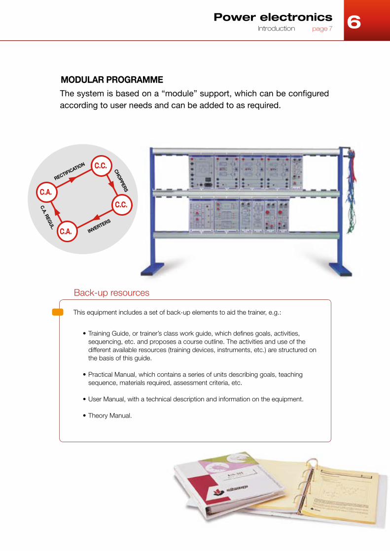
MODULAR PROGRAMMEThe system is based on a “module” support, which can be configured according to user needs and can be added to as required.
Back-up resources
This equipment includes a set of back-up elements to aid the trainer, e.g.:
• Training Guide, or trainer’s class work guide, which defines goals, activities, sequencing, etc. and proposes a course outline. The activities and use of the different available resources (training devices, instruments, etc.) are structured on the basis of this guide.
• Practical Manual, which contains a series of units describing goals, teaching sequence, materials required, assessment criteria, etc.
• User Manual, with a technical description and information on the equipment.
• Theory Manual.
C.A.
C.A.
C.C.
C.C.
RECTIFICATION
INVERTERS
C.A. REG
UL.
CH
OPPERS
6

6 Power electronicspage 8 The module support
These characteristics make the module an ideal working element for students, as the basis of their practical training, and also for the trainer as a demonstration device for presenting the theory and practical methodology.
The module support
Double module model.
1
3
2
4
6
5
The support consists of two elements: the front panel and the box. The front panel is made of recyclable shockproof polystyrene plastic, whose main features are its excellent surface finish, high dielectric strength and rigidity. The box is made of transparent polycarbonate, a rigid material with a high thermal and electric resistance and weatherproof. Both the polystyrene and the polycarbonate are free of cadmium, a substance classified as carcinogenic.
The printed information is a vital communication support and an element of great didactic value, associating each industrial component or circuit with the corresponding symbol in accordance with the IEC (International Electrotechnical Commission) standard.
Name: all the modules have a name printed on the front panel to facilitate identification and storage.
Electrical connection points: fixed to a socket type terminal for connection via a banana plug. The socket diameter depends on the type of electrical connection at each point: 4 mm for power connections using safety sockets, and 2 mm for control connections.
The rear connectors facilitate mounting the module on the vertical panels, and supply the voltage required for the internal circuits to function. For this purpose, the vertical frames and in general all the Alecop cabinets designed to house the modules are equipped with small interwired connectors.
The handles on the top and bottom of the devices enable the module to be fitted to and removed from the different frames, panels and cabinets designed for this purpose.
1 4
5
6
2
3
The module is a physical support with the following dimensions: 250 x 72 mm for the single module, 250 x 144 mm for the dual module and 250 x 216 mm for the triple module. These sizes make it easy to handle and suitable for work on panels or vertical frames. The figure shows a model of the module and indicates its main structural features.

6
Assembly and power supply systemThe assembly frame and the ALI-700 power supply module form the basis of the modular
programme and are required for all training module configuration requiring an electronic
power supply.
Power electronics Assembly and power supply system page 9
• This is a physical support for the modules, blocks and panels used for the practical activities.
• It transmits the electrical supply from the power supply modules to all the modules requiring it.
The frame dimensions are selected in accordance with the equipment to be mounted on the frame. Its horizontal structure consists of an aluminium section and the rectangular side supports are oven-dried painted iron sections.
As regards locating the frame on the work tables, it may be fixed (the frame can be fixed to the tables) or mobile (in which case it is supplied with removable legs with non-slip feet).
The module power supply and fixing systems consist of a series of connectors, into which the connection points located on the rear of the modules are inserted, exerting a slight pressure.
All the frame connectors are interwired in order to share a common voltage, guaranteeing a suitable power supply to the modules installed. The power is supplied via the ALI-700 module.
x: 1,2: frame height in tiers.xx: 10, 14, 18, 20, 22, 28, 36, 44: nº of insertable
single modules.
±15 V. SUPLLY
A supply source of ± 15 V. The power supply is transmitted via the table-mounted frame, and these voltages are also available at 2 mm terminals.
It includes the corresponding pilot LEDs to indicate correct output functioning, providing a nominal current of 2 A. It includes thermal and short-circuit protection, with automatic reset after a few seconds.
Ref.: 9EBxPxxCP
Ref.: MDULALI700
Table-mounted training frame Training Module

6 Power electronicspage 10 Controlled and uncontrolled rectification (EP1/EP2)
UNCONTROLLED RECTIFICATION
It enables the study of power diode-based rectifiers and their applications: single-phase, two-phase and three-phase half wave and full wave rectifiers.
• Based on the multi-panel concept.• Includes the base module and five panels for study
of the different bridges.• Operating range: 22 VAC - 380 VAC.• Safety connections and over-voltage and overload
protection.
PULSE GENERATOR
Sync and pulse train generator for ignition of the RTC-120 module thyristors.
• Control of up to 6 thyristors in three-phase bridge configuration.
• Three separate sync inputs, 10 – 380 VAC.• Six pulse outputs, simultaneous and electrically
insulated in pairs.• Time-shifted pulse train according to external or
internal set point.• Input terminal for enabling/inhibiting pulse outputs.• Requires ALI-700 ±15 V power supply module and
table-mounted frame.
CONTROLLED RECTIFICATION
It enables the study of power thyristor based controlled rectifiers and their applications: semi-controlled and fully controlled single-phase, two-phase and three-phase half wave and full wave rectifiers.
• Based on the multi-panel concept.• Includes the base module and eight panels for study
of the different bridges.• Operating range: 22 VAC - 380 VAC.• Safety connections and over-voltage and overload
protection.
Training module RNC-120
Training module RTC-120
Training module MGI-120
Ref: MDULRNC120
Ref: MDULMGI120
Ref: MDULRTC120
Equipment for studying uncontrolled rectification (EP1), controlled rectification and alternating
current regulation (EP2). It can be used at either low voltage (22/38 VAC, with CIR-120 and CRC-
120 charges) or mains voltage.
EP1/EP2
Controlled and uncontrolled rectification
6 Power electronics Controlled and uncontrolled rectification (EP1/EP2) page 11
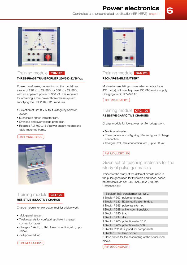
THREE-PHASE TRANSFORMER 220/380-22/38 Vac
Phase transformer, depending on the model has a ratio of 220 V. to 22/38 V. or 380 V. a 22/38 V, with an apparent power of 300 VA. It is required for obtaining a low-power three-phase system, supplying the RNC/RTC-120 modules.
• Selection of 22/38 V output voltage by selector switch.
• Successive phase indicator light.• Overload and over-voltage protection.• Requires ALI-700 ±15 V power supply module and
table-mounted frame.
RESISTIVE-INDUCTIVE CHARGE
Charge module for low-power rectifier bridge work.
• Multi-panel system.• Twelve panels for configuring different charge
connection types.• Charges: Y/A, R, L, R-L, free connection, etc., up to
50 Vef.• Self-powered fan.
Ref: MDULTRI120
Ref: MDULCIR120Ref: 9EQCNJDAEP
RESISTIVE-CAPACITIVE CHARGES
Charge module for low-power rectifier bridge work.
• Multi-panel system.• Three panels for configuring different types of charge
connection.• Charges: Y/A, free connection, etc., up to 63 Vef.
Ref: MDULCRC120
RECHARGEABLE BATTERY
Module for simulating counter-electromotive force (DC motor), with single-phase 230 VAC mains supply. Charging circuit 12 V/6.5 Ah.
Ref: MDULBAT120
Given set of teaching materials for the study of pulse generatorsTrainer for the study of the different circuits used inthe pulse generation for thyristors and triacs, basedon devices such as: UJT, DIAC, TCA-758, etc.Composed by:
1 Block nº 363: transformer 12+12 V.1 Block nº 393: pulse generator.1 Block nº 333: B250 rectification bridge.1 Block nº 355: pulse transformer.1 Block nº 288: uni-junction transistor.1 Block nº 296: triac.1 Block nº 294: diac.1 Block nº 265: potentiometer 10 K.1 Block nº 268: potentiometer 500K.6 Blocks nº 208: support for components. 1 Block nº 314: lamp holder.2 Base plates for the assembling of the educational blocks.
Training module TRI-120 Training module BAT-120
Training module CRC-120
Training module CIR-120

6 Power electronicspage 12 Switching power devices (EP3)
BIPOLAR TRANSISTOR
For studying the bipolar switching power transistor. It includes a PWM signal generator circuit for transistor control, which generates the input signal to the basic circuit (DRIVER), obtaining a 4 KHz rectangular signal with a variable duty cycle according to the user-accessible PWM potentiometer and Ton selector incorporated.
Equipped with a switching aid circuit via an anti-saturation diode.
MOSFET
Didactic module to study the switching behaviour of the MOSFET power transistor, including a MOSFET module, as well as its control circuitry. To control the MOSFET, a PWM signal generator is used which generates the input signal to the gate circuit (DRIVER); the latter is a rectangular 10 KHz. signal with a variable Ton of between 25 and 80 µsec, depending on the PWM potentiometer.
Training module TRS-200
Training module MTF-200
Ref: MDULTRS200
Ref: MDULMFT200
IGBT
Didactic module to study the switching behaviour of the IGBT (insulated gate bipolar transistor), included on the power IGBT module, as well as its control circuitry. To control the IGBT, a PWM signal generator is used which generates the input signal to the gate circuit (DRIVER), the latter is a rectangular 8 KHz. signal with a variable Ton of between 25 and 100 µsec, depending on the accessible potentiometer.
Training module GTR-200
Ref: MDULGTR200
EP3
Switching powerdevices
Set of modules enabling practical analysis of the behaviour, advantages, disadvantages and
problems of control of switching mode power devices.
Each module includes a block with the circuit’s most significant voltage and current measurements,
at reduced voltage and measured at the same point. The modules also include an electronic
overcurrent and short-circuit protection system.
6 Power electronicsa Switching power devices (EP3) page 13
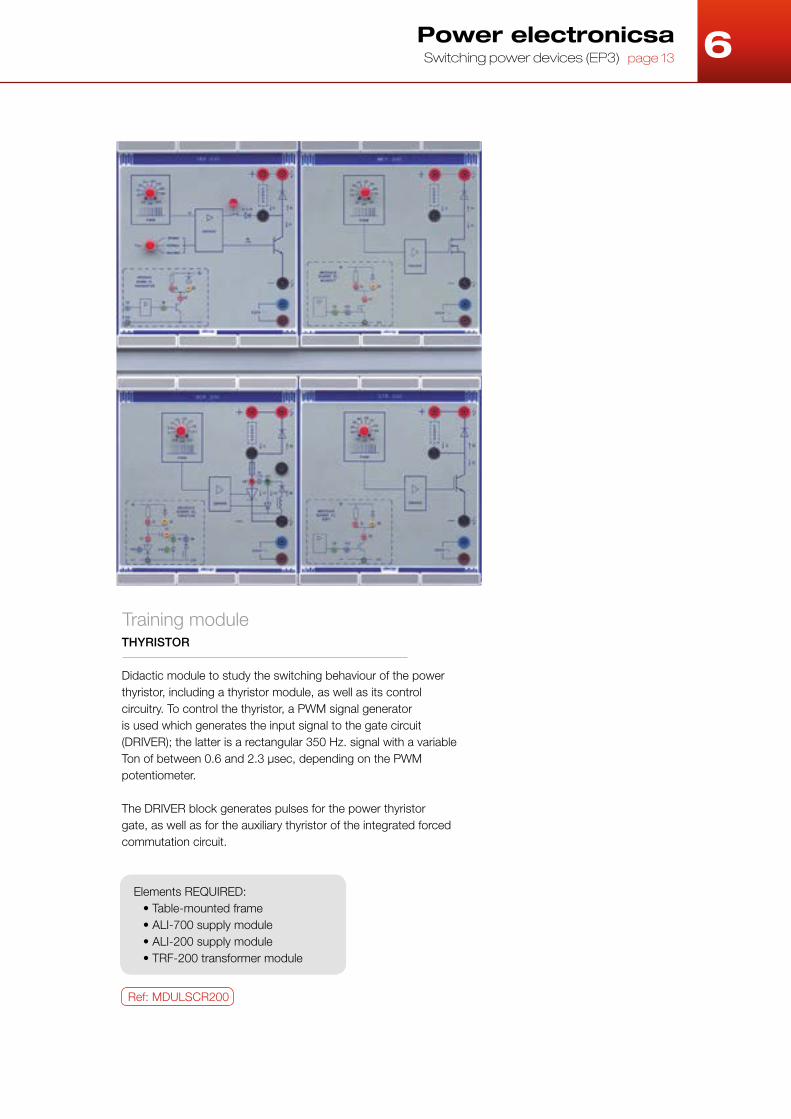
THYRISTOR
Didactic module to study the switching behaviour of the power thyristor, including a thyristor module, as well as its control circuitry. To control the thyristor, a PWM signal generator is used which generates the input signal to the gate circuit (DRIVER); the latter is a rectangular 350 Hz. signal with a variable Ton of between 0.6 and 2.3 µsec, depending on the PWM potentiometer.
The DRIVER block generates pulses for the power thyristor gate, as well as for the auxiliary thyristor of the integrated forced commutation circuit.
Elements REQUIRED:• Table-mounted frame• ALI-700 supply module• ALI-200 supply module• TRF-200 transformer module
Training module
Ref: MDULSCR200

6
CONTINUOUS POWER BUS
This didactic module contains a power supply of 310 V. continuous voltage, and can provide as far as a 10 A current. This is the constant direct voltage source for supplying the different convertors, and it distributes the mains voltage to the other power modules.
It incorporates 10 A fuses on the alternate and continuous side, protecting the module against line surges and short circuits.
The module disposes of a voltage sampling on the continuous bus; this signal is used as a protection measurement against possible high voltages on the BUS.
ISOLATION TRANSFORMER
230/230 VAC transformer isolating the ALI-200 module network. It has primary and secondary protection by means of 10 A fuses.
SAFETY DEVICE CENTRALISATION
This is a safety stage that must be included in all converters. It is a centralised protection block that protects the various convertor circuits against bus overvoltage and overloads. It also adapts the control signals to be sent to the RAMA modules of the converter in question in both amplitude and impedance, to act on the transistor base drivers.
Training module ALI-200
POWER MODULES
Training moduleTRF-200
Training moduleSEG-200
Ref: MDULALI200
Ref: MDULTRF200
Ref: MDULSEG200
Power electronicspage 14 DC/DC and AC/DC converters, choppers and inverters (EP4/EP5)
A set of modules that can be configured differently for studying DC/DC and AC/DC converters
(inverters or undulators), the various modulation techniques and their different applications
such as the regulation and control of DC and AC motors, uninterruptable power systems, etc.
EP4/EP5
DC/DC and AC/DC converters, choppers and inverters

6 Power electronics DC/DC and AC/DC converters, choppers and inverters (EP4/EP5) page 15
BRANCH OF BIPOLAR TRANSISTORS
These modules allow configuring of the power blocks of any type of transistorised converter, each of them forming one of the branches of the converter. The number of modules to use depends on the type of circuit which will be implemented (two for DC/DC converters and three for DC/AC converters).
Each module includes two power transistors as well as base DRIVER circuits required for control purposes.
It includes a JACK-type connector where the control signals from the SEG-200 module are received. These signals are optocoupled allowing a complete separation of the circuits from the power circuits.
Inside the module, a logic processor has been integrated which is responsible for detecting any
error in the RAM operation. If an error occurs, the processor blocks automatically and remains inoperative. The factors why the protection system lock the operation of the module are:
• Instantaneous intensity by transistors greater than 25 A with a longer duration than 4 msec.
• BUS voltage below 120 V.• Network supply failure.• Internal defects of circuit.
Elements REQUIRED:• Table-mounted frame• ALI-700 supply module• ALI-200 supply module• TRF-200 transformer module
Training module RAMA-200
Ref: MDULRAM200

6
SET POINT GENERATOR
This module generates three types of control set points: step, ramp and a set point that can be varied manually through potentiometric control.
PULSE WIDTH MODULATOR
It generates pulse width-modulated signals, providing the control commands to the power converters. It includes an oscillator block, which generates a triangular voltage and three 120° out -of-phase sinusoidal voltages, a “three-phase control” unit, for control of three-phase inverters, and a “single-phase control” unit for the single-phase inverters.
POWER MODULES
Training modulePWM-200
Ref: MDULSNG200
VOLTAGE-FREQUENCY CONVERTER
It converts the set point voltage applied at the input into a frequency using a voltage-controlled oscillator. It forms the control part of the transistorised inverter together with the TON-200 and MDX-200 modules, for asynchronous machine speed variation.
Training moduleVCO-200
Training module SNG-200
Ref: MDULVCO200
GENERATOR-INVERTER-PHASE MODULATOR
This module generates the control signals to be applied to the six transistors that make up the inverter bridge. It has a phase generator, a phase inverter in accordance with the set point sign and a modulating circuit.
Training moduleMDX-200
Ref: MDULMDX200z
TON DRIVER
The TON-200 module is in charge of the pulse width modulation coming from the voltage-frequency converter (VCO-200) for the control of the transistorised ondulator. It includes a pulse width adjustment circuit (Ton) and an overdrive circuit.
Training moduleTON-200
Ref: MDULTON200
Ref: MDULPWM200
Power electronicspage 16 DC/DC and AC/DC converters, choppers and inverters (EP4/EP5)
CURRENT LOOP IP CORRECTOR
Equipped with a current sensor, based on a Hall-effect cell, with an incorporated adjustable gain conditioner and three possible user-selectable control actions (proportional, integral and proportional-integral).
PI CORRECTOR SPEED LOOP
Provided with an adjustable gain conditioner circuit for tachometer, comparator of set point with feedback voltage, and three possible control operations (proportional, integral and proportional-integral).
Ref: MDULPII200 Ref: MDULPIV200
Training modulePII-200
Training modulePIV-200
A small set of two modules that can complement the sets of converters to enable study of closed
loop speed regulation.
EP6
Speed and currentregulation accessories

6 Power electronics Self-drive synchronous motor regulation accessories (EP7) page 17
CORRECTION
Didactic module for regulation of current of a three-phase load. It has been fitted with three current sensing devices, based on LEM cells with integrated conditioner circuit and three proportional-integral controllers with a PWM modulator at the output.
Training moduleCRR-200
Ref: MDULCRR200
SELF-DRIVE SYNCHRONOUS MOTOR
This motor has an absolute encoder coupled to its shaft with three optical sensors enabling detection of rotor position every 60°. Mounted on a bedplate that can be quickly and easily coupled to other machines, tacho, brake, etc. Its technical characteristics are as follows:
Training moduleAL-906
ADAPTER SIGNAL ENCODER
Didactic module responsible for generating the three current set points required to control the converter that supplies the self-steering synchronous motor AL-906.
Training moduleCSI-200
Ref: MDULCSI200
RECTIFIER BRIDGE
Training module which incorporates a monophase bridge rectifier.Needs 230 V. supply, monophase network voltage, providing 220V continuous voltage in the output. It can provide a maximum current of 7 A.
It has two ultra rapid fuses of 7 A. each, for protection of high currents and short circuits.
Training moduleREC-200
Ref: MDULREC200
CHARACTERISTICSReference PowerNominal voltageNominal speedShaft height
AL-9069MAK0906ZC370W230V1500rpm80
The set of elements described below complements the converter equipment to
enable study of speed regulation in self-drive synchronous motors.
EP7
Self-drive synchronous motorregulation accessories
6
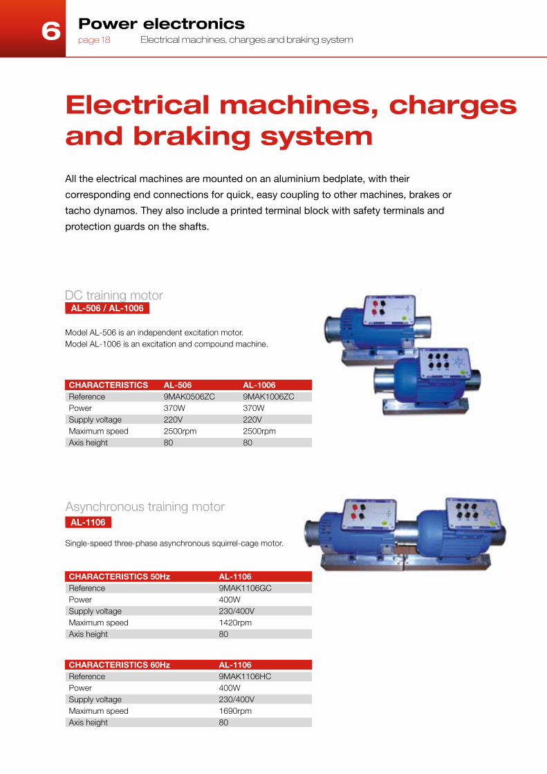
Model AL-506 is an independent excitation motor. Model AL-1006 is an excitation and compound machine.
DC training motorAL-506 / AL-1006
Single-speed three-phase asynchronous squirrel-cage motor.
Asynchronous training motorAL-1106
Power electronicspage 18 Electrical machines, charges and braking system
CHARACTERISTICSReference PowerSupply voltageMaximum speedAxis height
AL-5069MAK0506ZC370W220V2500rpm80
CHARACTERISTICS 50HzReference PowerSupply voltageMaximum speedAxis height
AL-11069MAK1106GC400W230/400V1420rpm80
CHARACTERISTICS 60HzReference PowerSupply voltageMaximum speedAxis height
AL-11069MAK1106HC400W230/400V1690rpm80
All the electrical machines are mounted on an aluminium bedplate, with their
corresponding end connections for quick, easy coupling to other machines, brakes or
tacho dynamos. They also include a printed terminal block with safety terminals and
protection guards on the shafts.
AL-10069MAK1006ZC370W220V2500rpm80
Electrical machines, charges and braking system

6
Didactic tachodynamo REO-444
System TP-200 rolling loads Transportable loads unit which disposes of a 100 Ohm./1000W rheostat, six 72 Ohm./200W resistances independent from each other (series, parallel or mixed connection), three inductances of 30mH./5 A and a condenser of 25 μF./450 V.
Power electronics Electrical machines, charges and braking system page 19
Ref: 9EQCATP200
CHARACTERISTICSReference ConstantMaximum speedAxis height
REO-444-809EQDINTQ8060 V/1000 r.p.m.1000 r.p.m.80 mm
REO-444-909EQDINTQ9060 V/1000 r.p.m.1000 r.p.m.80 mm
Braking system - bank
Lets you set the machine easily into the bed, under safety standards that prevent the operation of the bank improperly.
The control of the bed is made by potentiometric dials variable torque or speed, or by external signals that allow for SAD and control by computer.
Viewing every moment of the power, speed and torque exerted on the shaft of the bench, signals available on external connector.
Drive motor and brake of themachine undertest.
FUNCTION
GENERICSupply: single-phase net 190 to 250Vac 5.25 Amp. - 50/60HzType machines to be tested: - Type foot high 71, 80 and 90 mm. - Height 80 to 90 mm on Alecop profiles.Securing the machine under test by coupling.
OPERATING AS MOTOR DRIVESpeed: 0 to 2000 rpmRated: 800 wMaximum torque: 9.7 Nm
WORKS AS A BRAKEMaximum speed: 2450 rpmPar: 0 to 10 NmRated: 800 w
Technical specifications

alecop.com
Apdo. 81, Loramendi 1120500 Arrasate-MondragónGipuzkoa (España)Tel: +34 943 71 24 05Fax: +34 943 79 92 [email protected]
Alecop Didactic International
P.B. No. 6488DubaiUnited Arab Emirates.Tel: +971 4-3242131Fax: +971 [email protected]