power electronics - key technology for renewable · pdf filepower electronics - key technology...
TRANSCRIPT

Power Electronics - Key Technology for Renewable Energy Systems
Center of Reliable Power Electronics
Center of Reliable Power Electronics
Prof. Frede Blaabjerg
Professor, IEEE Fellow
Aalborg University Department of Energy Technology
Aalborg, Denmark
CORPE
www.corpe.et.aau.dk
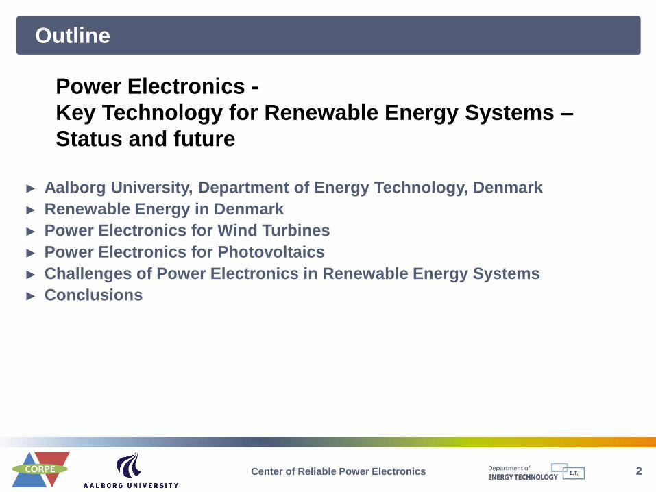
Outline
2 Center of Reliable Power Electronics
► Aalborg University, Department of Energy Technology, Denmark
► Renewable Energy in Denmark
► Power Electronics for Wind Turbines
► Power Electronics for Photovoltaics
► Challenges of Power Electronics in Renewable Energy Systems
► Conclusions
Power Electronics -
Key Technology for Renewable Energy Systems –
Status and future
3 Center of Reliable Power Electronics
Aalborg University
Department of Energy Technology,
Denmark
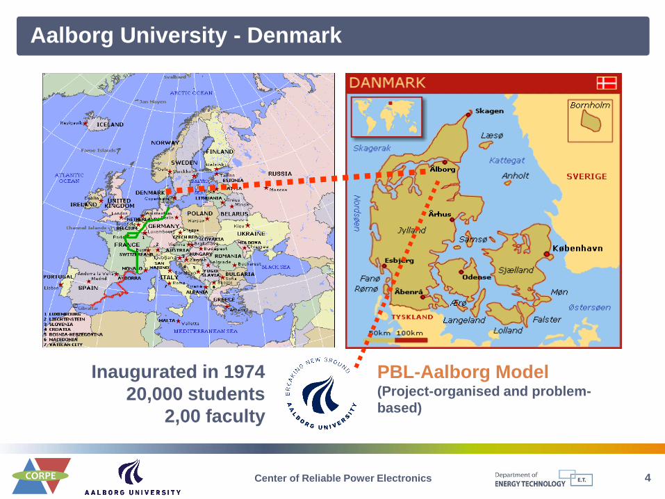
Aalborg University - Denmark
4 Center of Reliable Power Electronics
PBL-Aalborg Model (Project-organised and problem-
based)
Inaugurated in 1974
20,000 students
2,00 faculty

Aalborg University - Campus
5 Center of Reliable Power Electronics

Department of Energy Technology
6 Center of Reliable Power Electronics
Energy production - distribution - consumption - control
HEAT
LOADS POWER STATION
SOLAR CELLS
WIND TURBINE
MOTOR
PUMP
ROBOTICS
REFRIGERATOR
TELEVISION
LIGHT
TRANSFORMER
INDUSTRY
=
POWER SUPPLY
ac dc
TRANSFORMER
COMPEN - SATOR
FUEL CELLS
FUEL [
COMMUNICATION
COMBUSTION ENGINE
SOLAR ENERGY
TRANSPORT
3 3 3 1 - 3
3
DC
AC
~
POWER STATION
SOLAR CELLS
WIND TURBINE
MOTOR
PUMP
ROBOTICS
REFRIGERATOR
TELEVISION
LIGHT
TRANSFORMER
INDUSTRY
=
POWER SUPPLY
ac dc
TRANSFORMER
COMPEN - SATOR
FUEL CELLS
FUEL [
COMMUNICATION
COMBUSTION ENGINE
SOLAR ENERGY
TRANSPORT
3 3 3 1 - 3
3
DC
AC
~
DC
AC
DC
AC
PRIMARY
FUEL
CHP
Energy
Storages
Energy
Storages
FACTS/CUPS

Department of Energy Technology
7 Center of Reliable Power Electronics
Strategic Networks
• EMSD
• CEES
• ECPE
• VE-NET
• DUWET
• WEST
• VPP
• REN-DK
• HUB NORTH
• Energy Sponsor
Programme
Fluid Power and
Mechatronic
Systems
Fluid Mechanics
and Combustion
Electric Power
Systems
Power Electronic
Systems
Electrical
Machines
• 50+ VIP
• 70+ PhD
• 10+ Guest Researchers
• 10+ Research Assistants
• 22 TAP
Smart Grids and Active Networks
Wind Turbine Systems
Fluid Power in Wind and Wave Energy
Biomass
Photovoltaic Systems and Microgrids
Modern Power Transmission Systems
Fuel Cell and Battery Systems
Automotive and Industrial Drives
Efficient and Reliable Power Electronics
Thermoelectrics
Green Buildings
Multi-disciplinary Research Programmes Lab. Facilities
• Power Electronics
Systems
• Drive Systems Tests
• Fluid Power
• Power Systems & RTDS
• Micro Grid
• High Voltage
• dSPACE
• PV Converter &
Systems
• Laser Systems
• Fuel Cell Systems
• Battery Test
• EMC
• Vehicles Test Lab
• Biomass Conversion
Facilities
• Proto Type Facilities
Thermal Energy
Systems
Department of Energy Technology

8 Center of Reliable Power Electronics
Renewable Energy in Denmark

Energy and Power Challenge
9 Center of Reliable Power Electronics
Four main challenges in energy
Sustainable energy production (backbone, weather based, storage)
Energy efficiency
Mobility
Infrastructure
EU Set-plan (20-20-20) and beyond
Danish Climate Commision – Independent in 2050
Germany – no nuclear in the future (2022)
Globally large activity
Different initiatives

Renewable Electricity in Denmark
10 Center of Reliable Power Electronics
Key figures for proportion of renewable electricity
Key figures 2010 2011 2020 2035
Wind share of net generation in year 21.3% 29.4% 50%*
Wind share of consumption in year 22.0% 28.3%
RE share of net generation in year 32.8% 41.1% 100%*
RE share of net consumption in year 33.8% 39.0%
(Data source: Energinet.dk)
(Data source: Energinet.dk) (*target value)
2011 Renewable Electricity Generation
in Denmark

11
Energy and Power Challenge in DK
Very high coverage of distributed generation.
Bri
ef
Tech
no
logy
De
velo
pm
en
t
Center of Reliable Power Electronics

Development of Electric Power System in Denmark
12 Center of Reliable Power Electronics
From Central to De-central Power Generation
(Picture Source: Danish Energy Agency) (Picture Source: Danish Energy Agency)
13 Center of Reliable Power Electronics
Power Electronics for Wind Turbines
Renewable Energy System
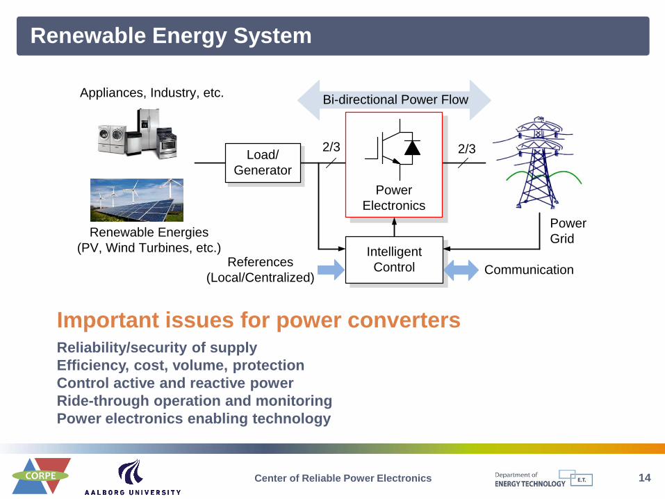
14 Center of Reliable Power Electronics
Important issues for power converters Reliability/security of supply
Efficiency, cost, volume, protection
Control active and reactive power
Ride-through operation and monitoring
Power electronics enabling technology
Load/
Generator
Power
Electronics
Intelligent
ControlReferences
(Local/Centralized)Communication
Bi-directional Power Flow
2/3 2/3
Appliances, Industry, etc.
Renewable Energies
(PV, Wind Turbines, etc.)
Power
Grid

Wind Turbine Development
15 Center of Reliable Power Electronics
Global installed wind capacity (up to 2012): 283 GW, 2012: 45 GW
Worldwide wind power capacity
(Giga Watts)
1980 1985 1990 1995 2000 2005 2011
50 kW
D 15 m
100 kW
D 20 m
500 kW
D 40 m
600 kW
D 50 m
2 MW
D 80 m
5 MW
D 124 m
7~8 MW
D 164 m
≈ 0% 10% 30% 100%Rating:Power
Electronics
2018 (E)
10 MW
D 190 m
Soft starter Rotor resistance control
Rotor power control
Full generator power control
Role:
Higher total capacity (59 % non-hydro renewables).
Larger individual size (average 1.8 MW, up to 8 MW).
More power electronics (up to 100 % rating coverage).

Requirements for Wind Turbine Systems
16 Center of Reliable Power Electronics
Wind Power
Conversion
System
1. Controllable I
2. Variable freq & U
P
Q
P
Q
1. Energy balance/storage
2. High power density
3. Strong cooling
4. Reliable
1. Fast/long P response
2. Controllable/large Q
3. freq & U stabilization
4. Low Voltage Ride Through
Generator side Grid side
General Requirements & Specific Requirements
Grid Codes for Wind Turbines
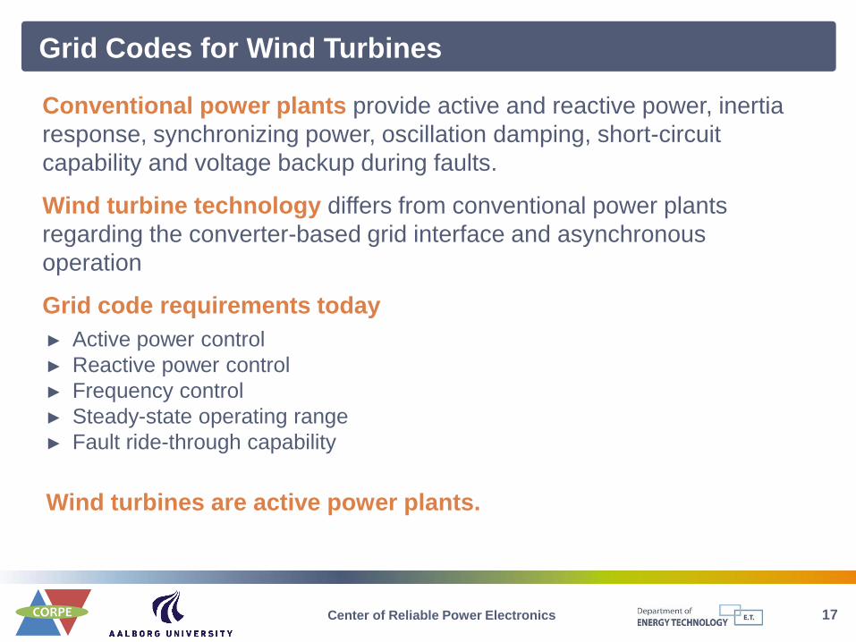
17 Center of Reliable Power Electronics
Conventional power plants provide active and reactive power, inertia
response, synchronizing power, oscillation damping, short-circuit
capability and voltage backup during faults.
Wind turbine technology differs from conventional power plants
regarding the converter-based grid interface and asynchronous
operation
Grid code requirements today
► Active power control
► Reactive power control
► Frequency control
► Steady-state operating range
► Fault ride-through capability
Wind turbines are active power plants.

Power Grid Standards – Ride-Through Operation
18
0
25
75
90
100
150 500 750 1000 1500
Voltage(%)
Time (ms)
DenmarkSpain
Germany
US
Keep connected
above the curves
Grid voltage dips vs. withstand time
100%
Iq /Irated
Vg (p.u.)
0.5
0
Dead band
0.9 1.0
20%
Reactive current vs. Grid voltage dips
Withstand extreme grid voltage dips.
Contribute to grid recovery by injecting Iq.
Higher power controllability of converter.
Requirements during grid faults
Center of Reliable Power Electronics
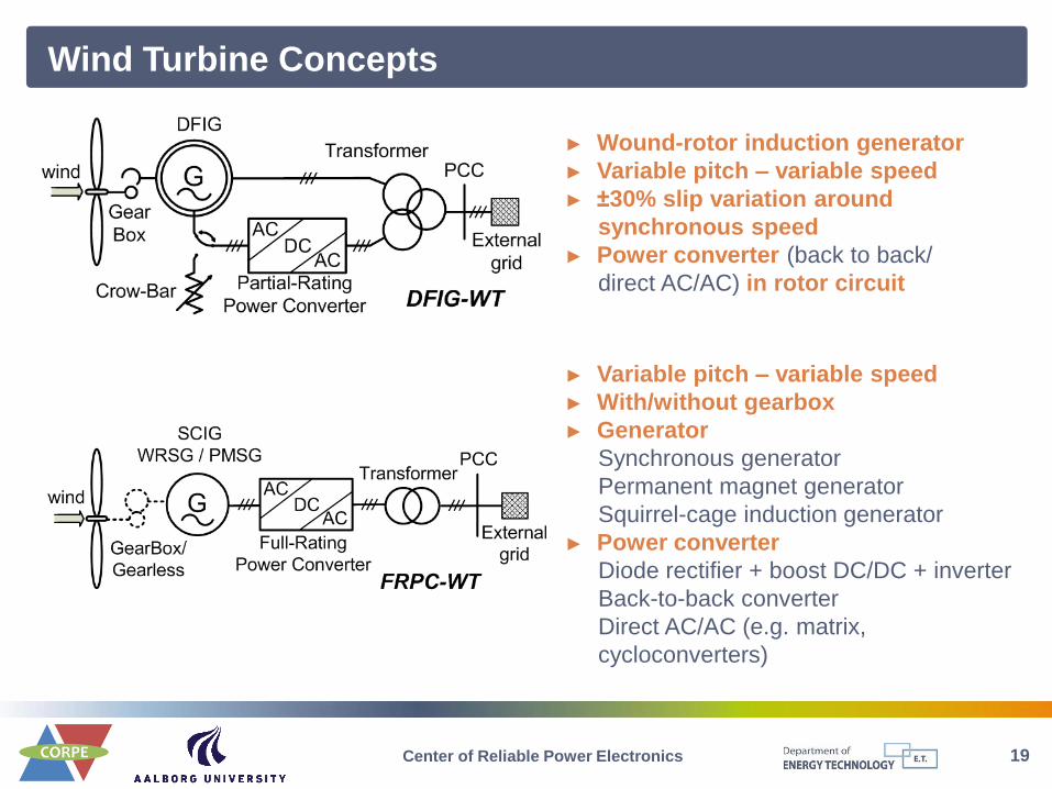
Wind Turbine Concepts
19 Center of Reliable Power Electronics
► Wound-rotor induction generator
► Variable pitch – variable speed
► ±30% slip variation around
synchronous speed
► Power converter (back to back/
direct AC/AC) in rotor circuit
► Variable pitch – variable speed
► With/without gearbox
► Generator
Synchronous generator
Permanent magnet generator
Squirrel-cage induction generator
► Power converter
Diode rectifier + boost DC/DC + inverter
Back-to-back converter
Direct AC/AC (e.g. matrix,
cycloconverters)

20
Back-to-back two-level voltage source converter
Proven technology
Standard power devices (integrated)
Decoupling between grid and generator (compensation for
non-symmetry and other power quality issues)
Need for major energy-storage in DC-link (reduced life-time and
increased expenses)
Power losses (switching and conduction losses)
Back-to-back VSC
Power Electronic Converters
Transformer
2L-VSC
Filter Filter
2L-VSC
Center of Reliable Power Electronics

21
Power converters
Proven technologies today
Boost and Voltage Source Converter to grid
Power Electronic Converters
Transformer
Filter Filter
Transformer
Filter Filter
Current Source Inverter to grid
Center of Reliable Power Electronics
22
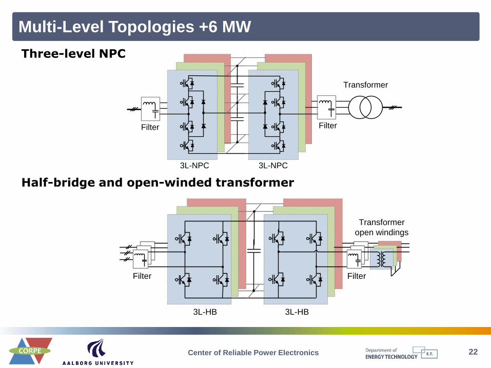
Multi-Level Topologies +6 MW
Transformer
3L-NPC
Filter Filter
3L-NPC
Transformer
open windings
Filter Filter
3L-HB 3L-HB
Three-level NPC
Half-bridge and open-winded transformer
Center of Reliable Power Electronics

23
5L-HB
Transformer
(open windings)
5L-HB
Filter Filter
3L-NPC
Transformer
(open windings)
5L-HB
Filter
Filter
Half-bridge, five-level
Three-level and five-level
Multi-Level Topologies +6 MW
Center of Reliable Power Electronics

24
...
Cell 1
Cell N
...
AC
DC
DC
AC
AC
DC
DC
AC
...
AC
DC
DC
AC
AC
DC
DC
AC
MFT
MFT
...
...
To grid
DC
DC
DC
AC
DC
DC
DC
AC
Rectifier
MVDC
To generator
Medium frequency transformer
Stacked output converter
Multi-Level Topologies +6 MW
Center of Reliable Power Electronics

Control Structure for a Wind Turbine System
25 Center of Reliable Power Electronics
Power has to be controlled by means of the aerodynamic system and has to react
based on a set-point given by a dispatched center or locally with the goal to maximize
the power production based on the available wind power.
IGen.
Fault ride through
& Grid support
Igrid
Vgrid
Vdc
Power Maximization
& Limitation
Inertia
Emulation
Power
Quality
Ancillary Services
WTS Specific Functions
Basic Control Functions
Current/Voltage
Control
Energy
Storage
Grid
Synchronization
Xf
θ
Ωgen.
DFIG
SG/PMSG
IG
I
S
D
Pmeas.,Qmeas.
AC
DC
AC
DC
Gear
Grid
FilterWind
Ambient
Temperature
Mission profilesSupervisory command
from DSO/TSO
Vdc
Control
PWMPWM
Monitoring and Control
Pin
Q
Po
Q
Communication

Current Development Example
26 Center of Reliable Power Electronics
Vestas V164 offshore turbine
Rated power: 8,000 kW
Rotor diameter: 164 m
Hub height: min. 105 m
Turbine concept: medium-speed gearbox,
variable speed, variable pitch, full-scale
power converter
Generator: permanent magnet
Vestas Wind Systems A/S Denmark
Target market: Big offshore farms
27
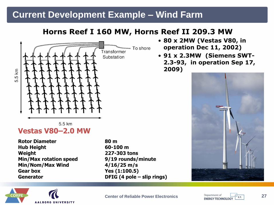
Vestas V80–2.0 MW
Horns Reef I 160 MW, Horns Reef II 209.3 MW • 80 x 2MW (Vestas V80, in
operation Dec 11, 2002)
• 91 x 2.3MW (Siemens SWT-2.3-93, in operation Sep 17, 2009)
Rotor Diameter 80 m Hub Height 60-100 m Weight 227-303 tons Min/Max rotation speed 9/19 rounds/minute Min/Nom/Max Wind 4/16/25 m/s Gear box Yes (1:100.5) Generator DFIG (4 pole – slip rings)
Current Development Example – Wind Farm
Center of Reliable Power Electronics

Improved Performance of Wind Turbines
Variable speed wind turbine integrated with a battery storage system
Center of Reliable Power Electronics 27

29 Center of Reliable Power Electronics
Power Electronics for Photovoltaics
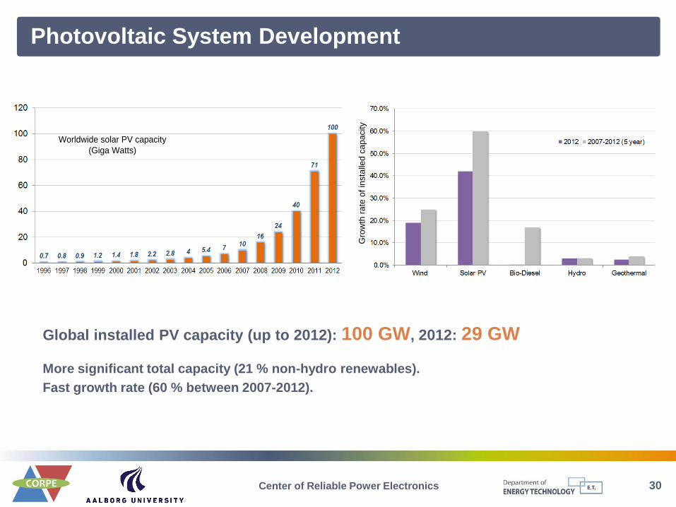
Photovoltaic System Development
30 Center of Reliable Power Electronics
More significant total capacity (21 % non-hydro renewables).
Fast growth rate (60 % between 2007-2012).
Global installed PV capacity (up to 2012): 100 GW, 2012: 29 GW
Worldwide solar PV capacity
(Giga Watts)
Gro
wth
ra
te o
f in
sta
lled
ca
pa
city

Requirements for Photovoltaic Systems
31 Center of Reliable Power Electronics
General Requirements & Specific Requirements
Photovoltaic
Conversion
System
1. Controllable I/U
P P
Q
1. High efficiency
2. Low common mode I
3. Temp. insensitive
4. Reliable
1. Low THD
PV panel side Grid side
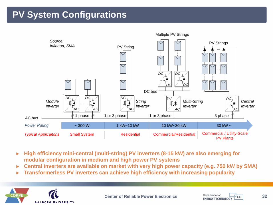
PV System Configurations
32 Center of Reliable Power Electronics
► High efficiency mini-central (multi-string) PV inverters (8-15 kW) are also emerging for
modular configuration in medium and high power PV systems
► Central inverters are available on market with very high power capacity (e.g. 750 kW by SMA)
► Transformerless PV inverters can achieve high efficiency with increasing popularity
AC bus
AC
DC
AC
DC
DC
DC
DC
DC
AC
DC
AC
DC
AC
DC bus
DC
PV StringsPV String
Multiple PV Strings
Module
Inverter
3 phase1 or 3 phase1 phase 1 or 3 phase
Source:
Infineon, SMA
Power Rating ~ 300 W 1 kW~10 kW 10 kW~30 kW 30 kW ~
Typical Applicaitons Small System Residential Commercial/Residential Commercial / Utility-Scale
PV Plants
String
Inverter
Multi-String
Inverter
Central
Inverter
33
PV
Arr
ays
Filt
er
LF
Transformer
PV
Arr
ays
Filt
er
HF
Transformer
PV
Arr
ays
Filt
er
*
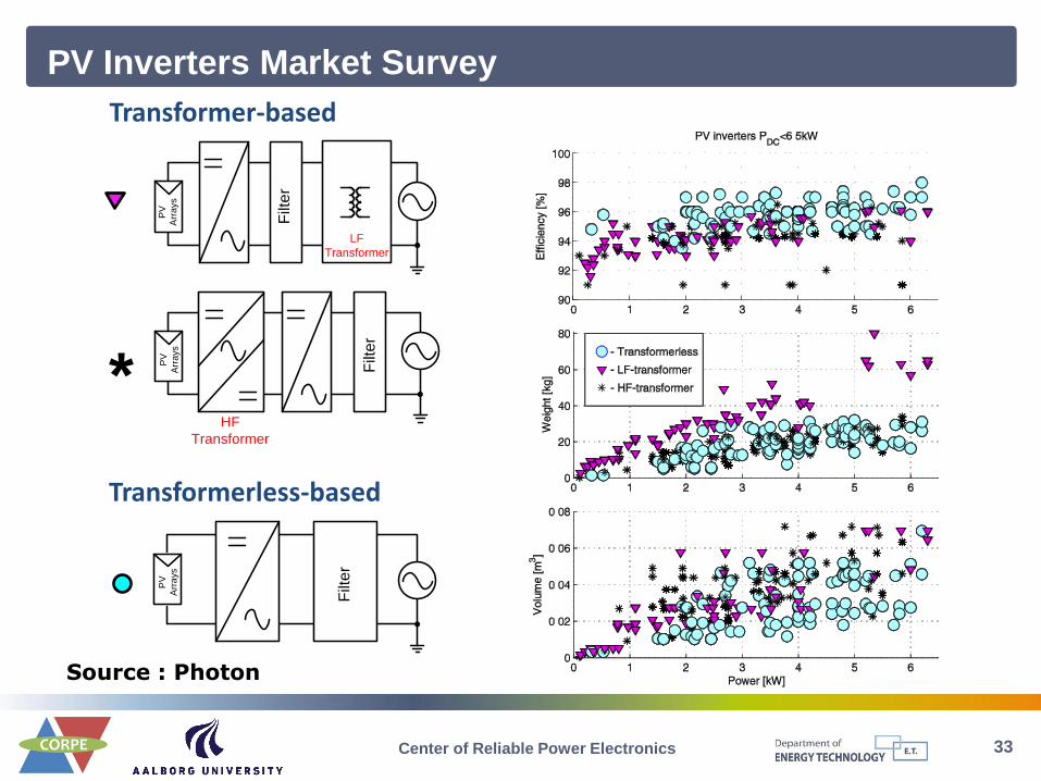
Transformer-based
PV Inverters Market Survey
Transformerless-based
Source : Photon
Center of Reliable Power Electronics
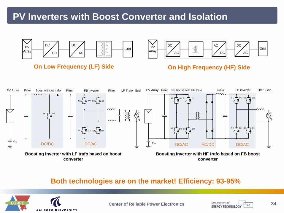
34 34
Both technologies are on the market! Efficiency: 93-95%
DC
ACGrid
PV
Array
DC
DC
On Low Frequency (LF) Side
DC
AC
GridPV
Array
DC
AC
AC
DC
On High Frequency (HF) Side
PV Inverters with Boost Converter and Isolation
DC/AC DC/AC AC/DC
Grid
N
L
FilterFilterFB boost with HF trafo FB inverterFilterPV Array
S5 S7
S6 S8
S1 S3
S2 S4
D1 D3
D2 D4
D5 D7
D6 D8
VPE
Boosting inverter with HF trafo based on FB boost
converter
DC/ACDC/DC
Grid
N
L
FilterFilterBoost without trafo FB inverterFilterPV Array
S5
S1 S3
S2 S4
D1 D3
D2 D4
D5
LF Trafo
VPE
Boosting inverter with LF trafo based on boost
converter
Center of Reliable Power Electronics

35 35
DC
DC
DC
ACGrid
PV
Array
•High efficiency (>95%)
•Leakage current problem
•Safety issue
•Efficiency > 96%
•Extra diode to bypass boost when Vpv > Vg
•Boost with rectified sinus reference
N
LS5
S1 S3
S2 S4
D1 D3
D2 D4
D5
VPELeakage circulating current
•Time sharing configuration
Full Bridge Inverter with Boost Converter
N
LS5
S1 S3
S2 S4
D1 D3
D2 D4
D5
VPELeakage circulating current
• Typical configuration
Transformerless PV Topologies with Boost Stage
Center of Reliable Power Electronics
36 36
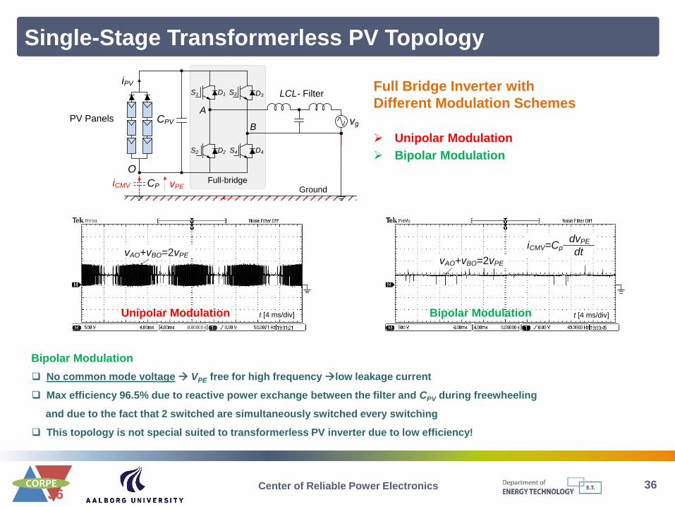
No common mode voltage VPE free for high frequency low leakage current
Max efficiency 96.5% due to reactive power exchange between the filter and CPV during freewheeling
and due to the fact that 2 switched are simultaneously switched every switching
This topology is not special suited to transformerless PV inverter due to low efficiency!
Single-Stage Transformerless PV Topology
Center of Reliable Power Electronics
Full-bridge
CPV
O
vg
LCL- FilterD1
D2
D3
D4
A
BPV Panels
iPV
CP
S1
S2
S3
S4
iCMVGround
vPE
Full Bridge Inverter with
Different Modulation Schemes
Unipolar Modulation
Bipolar Modulation
vAO+vBO=2vPEvAO+vBO=2vPE
t [4 ms/div] t [4 ms/div]
iCMV=CpdvPE
dt
Bipolar Modulation Unipolar Modulation
Bipolar Modulation
37 37
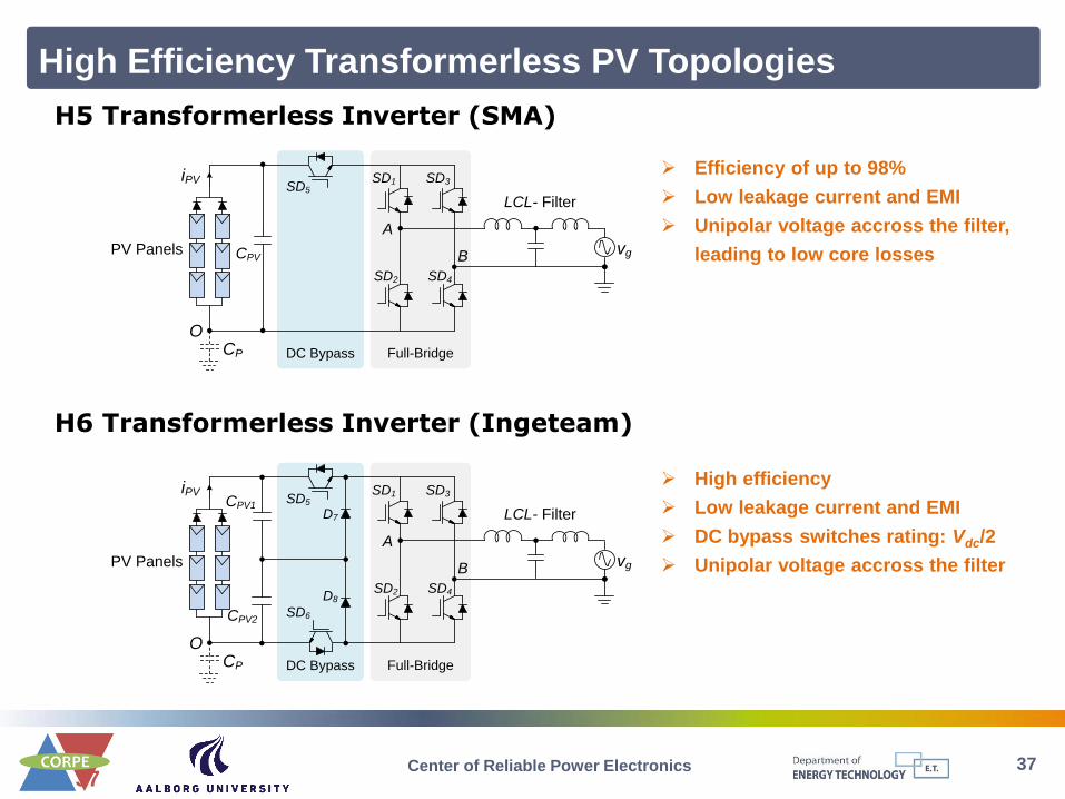
High Efficiency Transformerless PV Topologies
Center of Reliable Power Electronics
DC Bypass
CPV1
vg
CPV2
SD5
SD6
D7
D8
Full-Bridge
iPV
LCL- Filter
SD1
SD2
SD3
SD4
O
A
BPV Panels
CP
DC Bypass
vgCPV
SD5
Full-Bridge
iPV
LCL- Filter
SD1
SD2
SD3
SD4
O
A
BPV Panels
CP
H5 Transformerless Inverter (SMA)
H6 Transformerless Inverter (Ingeteam)
Efficiency of up to 98%
Low leakage current and EMI
Unipolar voltage accross the filter,
leading to low core losses
High efficiency
Low leakage current and EMI
DC bypass switches rating: Vdc/2
Unipolar voltage accross the filter

38 38
High Efficiency Transformerless PV Topologies
Center of Reliable Power Electronics
AC Bypass
SD5
SD6
Full-Bridge
iPV
CPV
vg
SD1
SD2
SD3
SD4
LCL- Filter
O
A
BPV Panels
CP
AC BypassFull-Bridge
iPV
vg
SD1
SD2
SD3
SD4
LCL- Filter
O
A
BPV Panels
CP
CPV1
CPV2
SD5
HERIC - Highly Efficient and Reliable Inverter Concept (Sunways)
FB-ZVR – Full Bridge with a Zero Voltage Rectifier (T. Kerekes, etc)
High efficiency of up to 97%
Very low leakage current and EMI
Low core losses
Efficiency of up to 96%
Low leakage current and EMI
Unipolar voltage accross the filter,
leading to low core losses

39 39
NPC Topologies for PV Applications
Three-level output. Requires double PV voltage input in comparison with FB.
The switching ripple in the current equals 1x switching frequency high filtering needed
Voltage across filter is unipolar low core losses
VPE is equal –Vpv/2 without high frequency component low leakage current and EMI
High max efficiency 98% due to no reactive power exchange, as reported by Danfoss Solar TripleLynx
series (10/12.5/15 kW)
Center of Reliable Power Electronics
CPV1
CPV2
D5
D6
LCL- Filter
SD1
SD2
SD3
SD4
AB
N
vg
CPV1
CPV2
LCL- Filter
SD1
SD2
SD3
SD4
AB
N
vg
Neutral clampled half-bridge Conergy neutral point clampled inverter

Control Structure for a PV System
40 Center of Reliable Power Electronics
Basic functions –
all grid-tied inverters
► Grid current control
► DC voltage control
► Grid synchronization
PV specific functions –
common for PV inverters
► Maximum power point tracking – MPPT
► Anti-Islanding (VDE0126, IEEE1574, etc.)
► Grid monitoring
► Plant monitoring
► Sun tracking (mechanical MPPT)
Ancillary support –
in effectiveness
► Voltage control
► Fault ride-through
► Power quality
► …
PV Panels/
StringsPPV
Boost
iPV vPV
vg
ig
Q
Ambient
Temperature
Solar
Irradiance
DC
DC
DC
AC
CPV Cdc Inverter Filter
vdc PWMPWM
Xfilter
Communication Supervisory command
from DSO/TSO
Mission Profiles
Grid2/3
PV Panel/Plant
Monitoring
Maximum Power
Point Tracking
Grid Support
(V, f, Q control)Energy Storage
Ancillary Services
PV System Specific Functions
Basic Control Functions
Current/Voltage Control
Fault Ride Through
Grid SynchronizationVdc Control
Monitoring and Control
Anti-Islanding
Protection
Harmonic Compensation Constant Power Generation Control
Po

41 Center of Reliable Power Electronics
Challenge of Power Electronics in Renewable Energy
Systems

42 Center of Reliable Power Electronics
Cost of Energy (COE) T
yp
ica
l L
CO
E r
an
ge
s U
SD
/ k
Wh
Cost of fossil fuel
generation
&Cap O M
Annual
C CCOE
E
CCap – Capital cost
CO&M– Operation and main. cost
EAnnual – Annual energy production
Determining factors for renewables
- Capacity growth
- Technology development
43 Center of Reliable Power Electronics
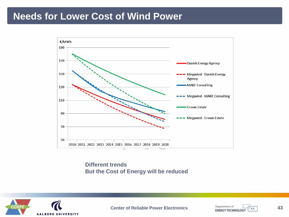
Needs for Lower Cost of Wind Power
Different trends
But the Cost of Energy will be reduced
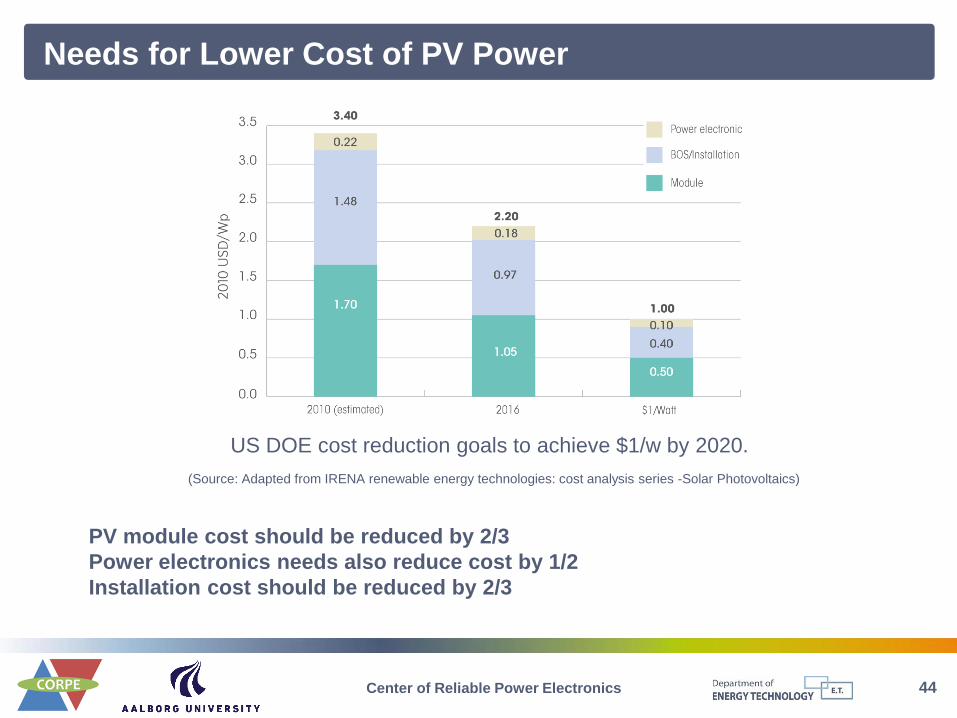
44 Center of Reliable Power Electronics
Needs for Lower Cost of PV Power
PV module cost should be reduced by 2/3
Power electronics needs also reduce cost by 1/2
Installation cost should be reduced by 2/3
US DOE cost reduction goals to achieve $1/w by 2020.
(Source: Adapted from IRENA renewable energy technologies: cost analysis series -Solar Photovoltaics)
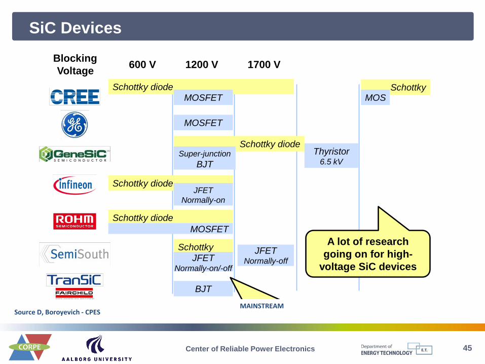
SiC Devices
45
Source D, Boroyevich - CPES
Major SiC Device Developers
January 27, 2012 DB-23
600 V 1200 V 1700 V 3-7 kV 10 kV
Schottky
Blocking
Voltage
JFET Normally-on/-off
JFET Normally-off
Schottky diode
Schottky diode JFET
Normally-on
Schottky diode Super-junction
BJT
Thyristor 6.5 kV
BJT
MOSFET
Schottky diode
Schottky MOSFET MOS
MOSFET
Mainstream: 1.2 kV switches
A lot of research
going on for high-
voltage SiC devices
MAINSTREAM
Center of Reliable Power Electronics
First PV inverter based on SiC JFET
46
• SMA 20000TLHE-10 – 20 kW, 3 phase – 99.2%
• Light weight – 45 kg (1/2 of normal)
• Cooling minimized
• Conergy topology realized with Infineon
modules
• SiC JFET with IGBT free whelling
Source Photon Intl – Dec 2011
vc
N
vb va
N
Ta2 Ta3
Tb2 Tb3
Tc2 Tc3
Tb1 Tc1Ta1
Tb4 Tc4Ta4
Source : Infineon – Easy 1 b Modules
Center of Reliable Power Electronics

Simpler topologies with SiC JFET
47
vc
N
vb vaTa2
Tb1 Tc1Ta1
Tb2 Tc2
• Back to 2 level topologies!
• “Only” by doubling the switching frequency to 32 kHz, same efficiency of 98% as NPC-3L@16 kHz
• Half components count and lower footprint/weight
• Practical zero-reverse recovery with SiC diodes
Source B. Burger - Frunhofer
Center of Reliable Power Electronics
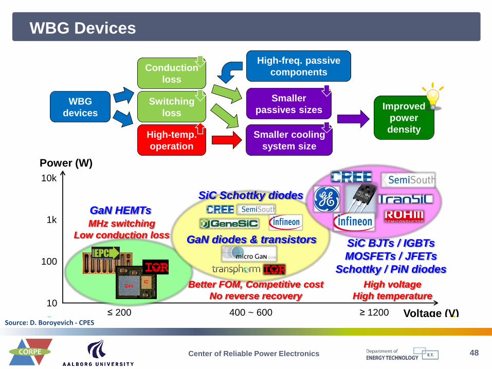
WBG Devices
48
Wide-Band-Gap Devices: Ways to Higher Power Density
January 27, 2012 DB-4
WBG
devices
≤ 200 400 ~ 600 ≥ 1200 Voltage (V)
Power (W)
10
100
1k
10k
GaN HEMTs MHz switching
Low conduction loss
Conduction
loss
Switching
loss
High-temp.
operation
Smaller cooling
system size
High-freq. passive
components
Smaller
passives sizes Improved
power
density
GaN diodes & transistors
SiC Schottky diodes
Better FOM, Competitive cost
No reverse recovery
SiC BJTs / IGBTs
MOSFETs / JFETs
Schottky / PiN diodes
High voltage
High temperature
Source: D. Boroyevich - CPES
Center of Reliable Power Electronics

Failures of Power Electronic Systems
49 Center of Reliable Power Electronics
Field Experience of Wind Turbines – Normalized Downtime
(Source: Reliawind, Report on Wind Turbine Reliability Profiles – Field Data Reliability Analysis, 2011.)
Power module
Rotor
module
Control
& Commons
NacelleDrive
trainAuxiliary system Structure
Power
converter
18.4% Pitch
system
23.3% Yaw system
7.3%Gearbox
4.7%
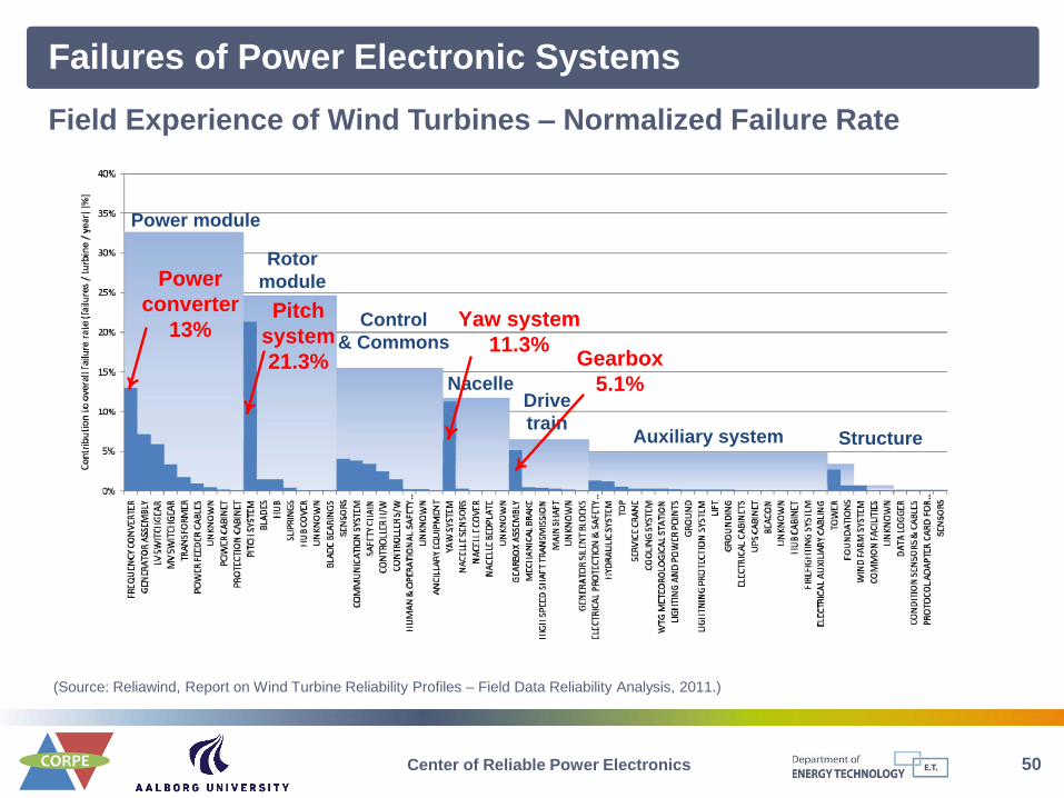
Failures of Power Electronic Systems
50 Center of Reliable Power Electronics
Power module
Rotor
module
Control
& Commons
NacelleDrive
trainAuxiliary system Structure
Power
converter
13%Pitch
system
21.3%
Yaw system
11.3%Gearbox
5.1%
Field Experience of Wind Turbines – Normalized Failure Rate
(Source: Reliawind, Report on Wind Turbine Reliability Profiles – Field Data Reliability Analysis, 2011.)
Failures of Power Electronic Systems
51 Center of Reliable Power Electronics
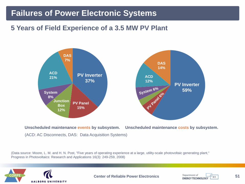
5 Years of Field Experience of a 3.5 MW PV Plant
(Data source: Moore, L. M. and H. N. Post, "Five years of operating experience at a large, utility-scale photovoltaic generating plant,"
Progress in Photovoltaics: Research and Applications 16(3): 249-259, 2008)
PV Inverter
37%
PV Panel
15%
Junction
Box
12%
System
8%
ACD
21%
DAS
7%
PV Inverter
59%
PV P
anel
6%System 6%
ACD
12%
DAS
14%
Unscheduled maintenance events by subsystem. Unscheduled maintenance costs by subsystem.
(ACD: AC Disconnects, DAS: Data Acquisition Systems)

52 Center of Reliable Power Electronics
Semiconductor 21%
Capacitor30%
PCB26%
*Data sources: Wolfgang E., “Examples for Failures in Power Electronics Systems,” in EPE Tutorial ‘Reliability of Power Electronic Systems’,
April 2007.
Failure root causes distribution for power electronic systems*
(% may vary for different applications and designs)
Critical Components in Power Electronic Systems
(http://www.alibaba.com)
(www.abb.com)
53 Center of Reliable Power Electronics
Approaches to Reduce Cost-of-Energy
&Cap O M
Annual
C CCOE
E
CCap – Capital cost
CO&M– Operation and main. cost
EAnnual – Annual energy production
Approaches Important and related factors Potential
Lower CCap Production / Policy +
Lower CO&M Reliability / Design / Labor ++
Higher Eannual Reliability / Capacity / Efficiency / Location +++
Reliability is an efficient way to reduce COE – lower CO&M & higher Eannual !
54 Center of Reliable Power Electronics
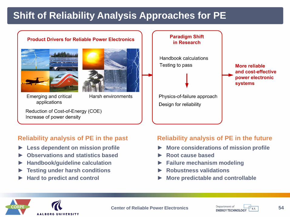
Shift of Reliability Analysis Approaches for PE
Reliability analysis of PE in the future
► More considerations of mission profile
► Root cause based
► Failure mechanism modeling
► Robustness validations
► More predictable and controllable
Reliability analysis of PE in the past
► Less dependent on mission profile
► Observations and statistics based
► Handbook/guideline calculation
► Testing under harsh conditions
► Hard to predict and control
55 Center of Reliable Power Electronics
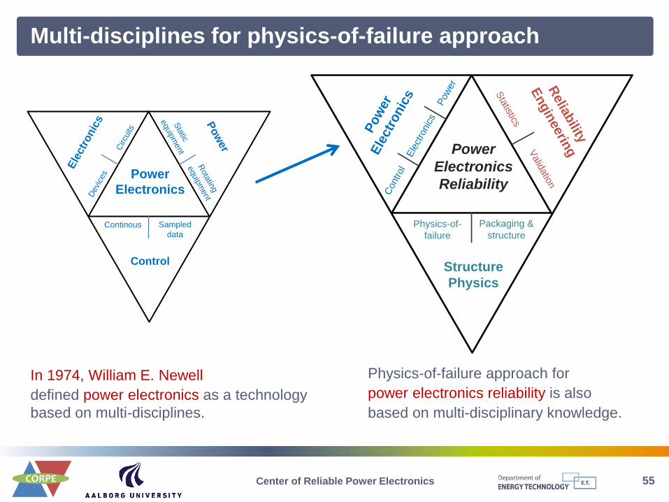
Multi-disciplines for physics-of-failure approach
Ele
ctr
onic
s Pow
er
Control
Power
Electronics
Circu
its
Sta
tic
equip
ment
Rota
ting
equip
ment
Continous
Devi
ces
Sampled
data
In 1974, William E. Newell
defined power electronics as a technology
based on multi-disciplines.
Physics-of-failure approach for
power electronics reliability is also
based on multi-disciplinary knowledge.
Pow
er
Ele
ctr
onic
s
Relia
bility
Engin
eerin
g
Structure
Physics
Power
Electronics
Reliability
Ele
ctro
nic
s
Sta
tistics
Valid
atio
n
Physics-of-
failure
Control
Packaging &
structure
Pow
er

56 Center of Reliable Power Electronics
Reliability prediction of power electronics
Robustness margins
Mean cumulative failure rate
(MCF) Curve
Lifetime
Loading
profileReliability
information
Converter
Design
Mission
Profile
Stress Analysis
· Mission analysis
· Load estimation
· ...
Strength Modeling
· Failure mechanism
· Accelerating test
· Field feedback
· ...
Variation & Statistics
· System combination
· Stress/devices variation
· Production robustness
· ...
Lifetime
2L converter
690 Vrms
Filter
2L converter
Grid
1.1 kVDC
IGBT
Wind turbine
Generator
0%
5%
10%
0 1000 2000
M…
57 Center of Reliable Power Electronics
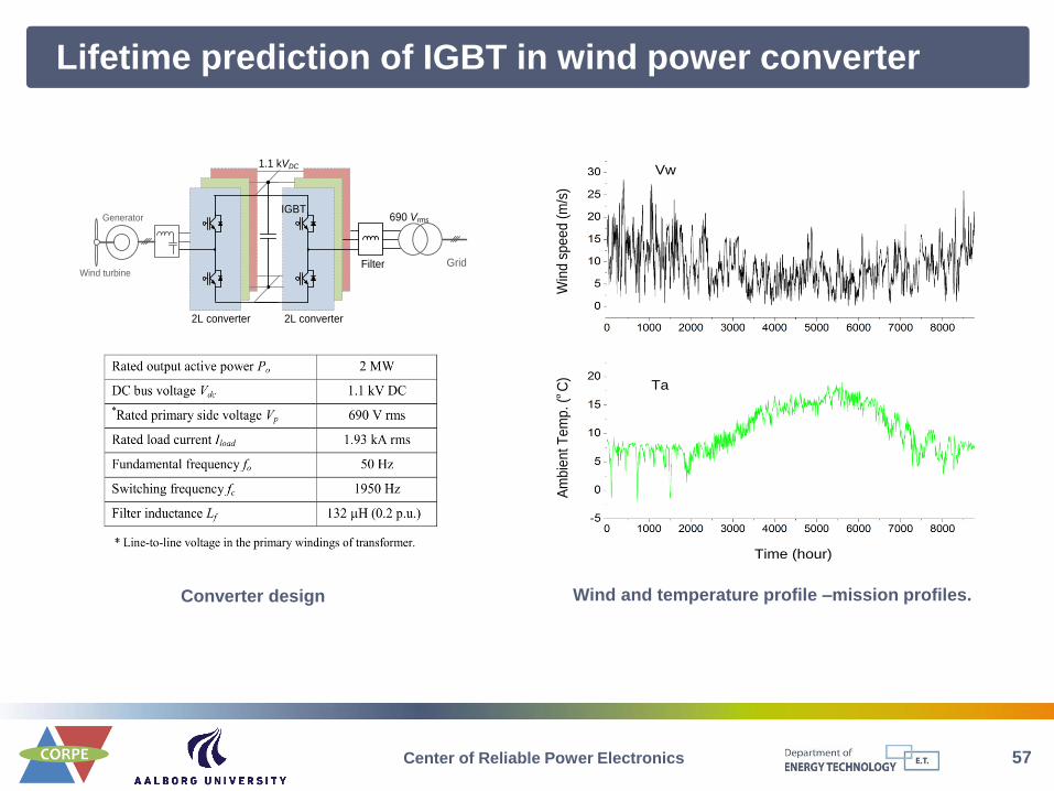
Lifetime prediction of IGBT in wind power converter
Converter design
2L converter
690 Vrms
Filter
2L converter
Grid
1.1 kVDC
IGBT
Wind turbine
Generator
Win
d s
pe
ed
(m
/s)
Am
bie
nt T
em
p. (º
C)
Time (hour)
Vw
Ta
Wind and temperature profile –mission profiles.
58 Center of Reliable Power Electronics
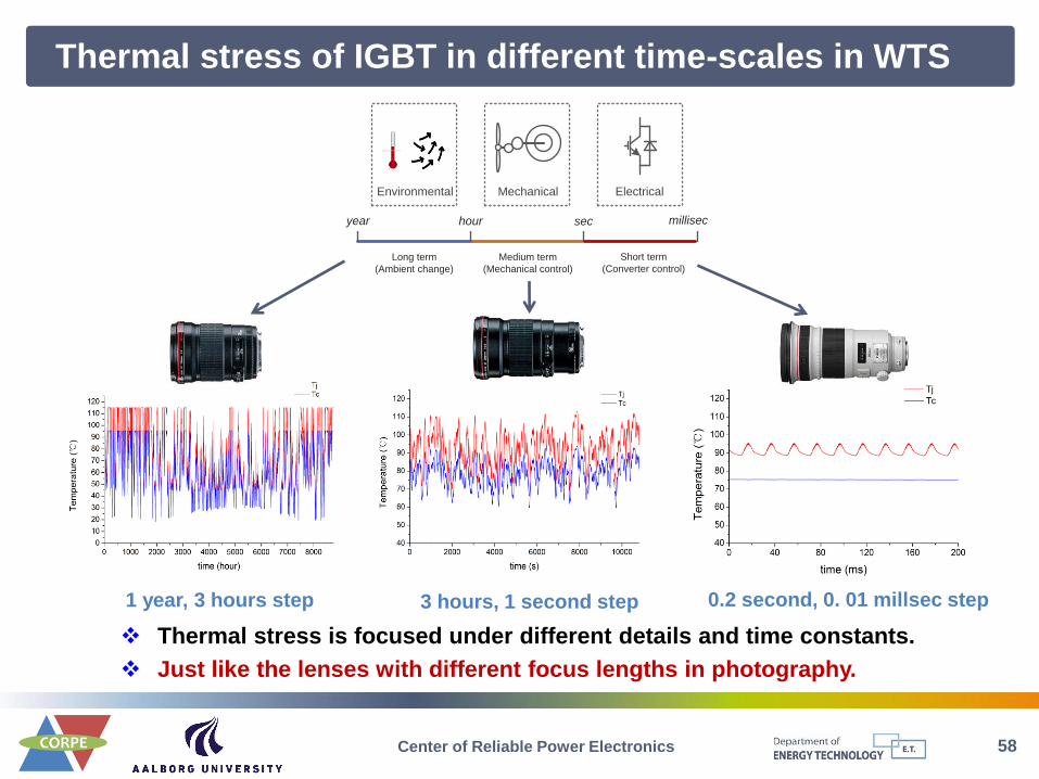
Thermal stress of IGBT in different time-scales in WTS
Mechanical ElectricalEnvironmental
sec
Medium term
(Mechanical control)
Long term
(Ambient change)
Short term
(Converter control)
houryear millisec
Thermal stress is focused under different details and time constants.
Just like the lenses with different focus lengths in photography.
1 year, 3 hours step 3 hours, 1 second step 0.2 second, 0. 01 millsec step
59 Center of Reliable Power Electronics
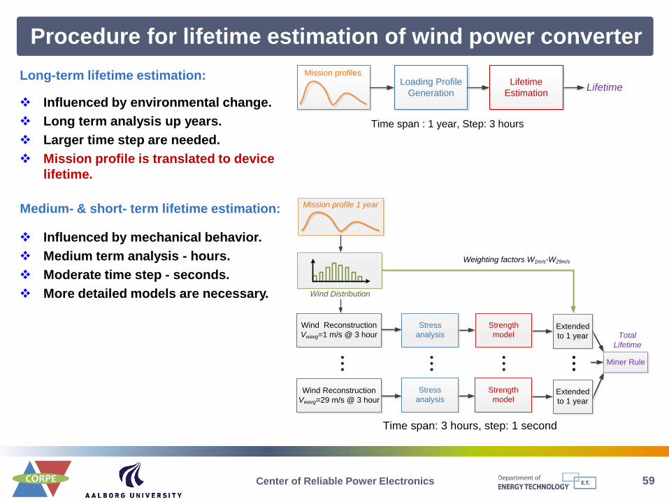
Procedure for lifetime estimation of wind power converter
Stress
analysis Total
Lifetime
Strength
model
Mission profile 1 year
Wind Distribution
Wind Reconstruction
Vwavg=1 m/s @ 3 hour
Wind Reconstruction
Vwavg=29 m/s @ 3 hour
Extended
to 1 year
Extended
to 1 year
Weighting factors W1m/s-W29m/s
Miner Rule…
…
…
…
Stress
analysis
Strength
model
Time span: 3 hours, step: 1 second
Loading Profile
Generation Lifetime
Lifetime
Estimation
Mission profiles
Time span : 1 year, Step: 3 hours
Influenced by environmental change.
Long term analysis up years.
Larger time step are needed.
Mission profile is translated to device
lifetime.
Long-term lifetime estimation:
Medium- & short- term lifetime estimation:
Influenced by mechanical behavior.
Medium term analysis - hours.
Moderate time step - seconds.
More detailed models are necessary.
60 Center of Reliable Power Electronics
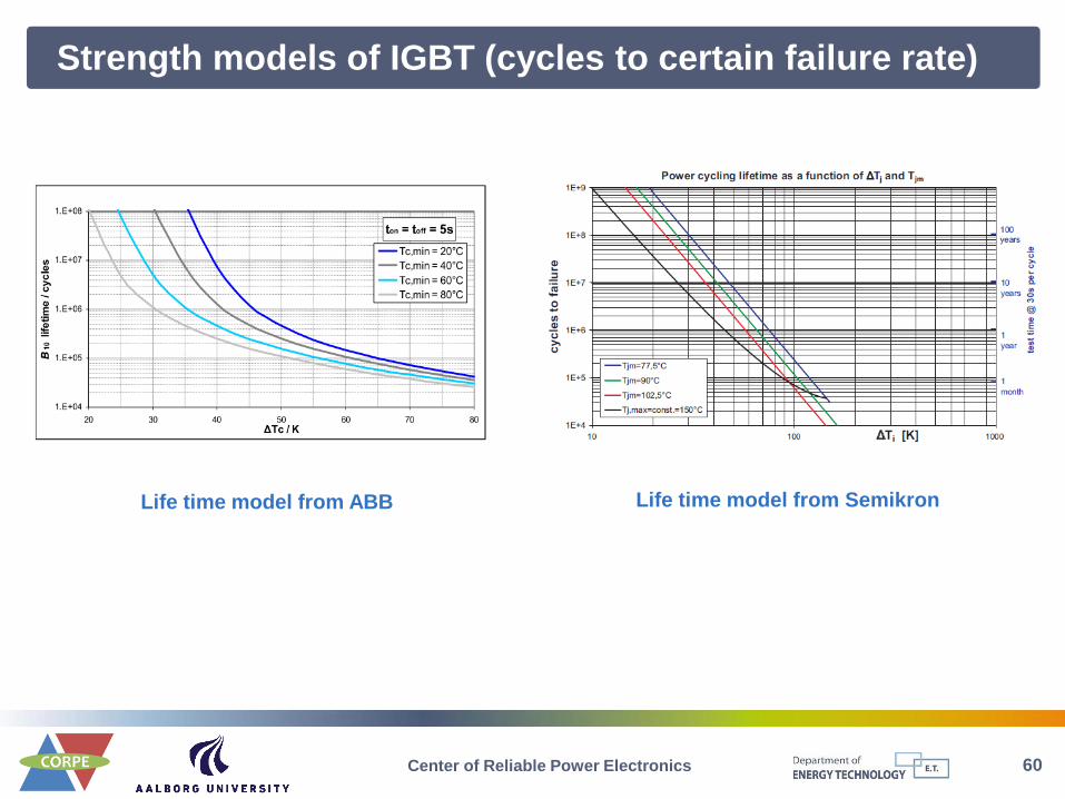
Strength models of IGBT (cycles to certain failure rate)
Life time model from ABB Life time model from Semikron
61 Center of Reliable Power Electronics
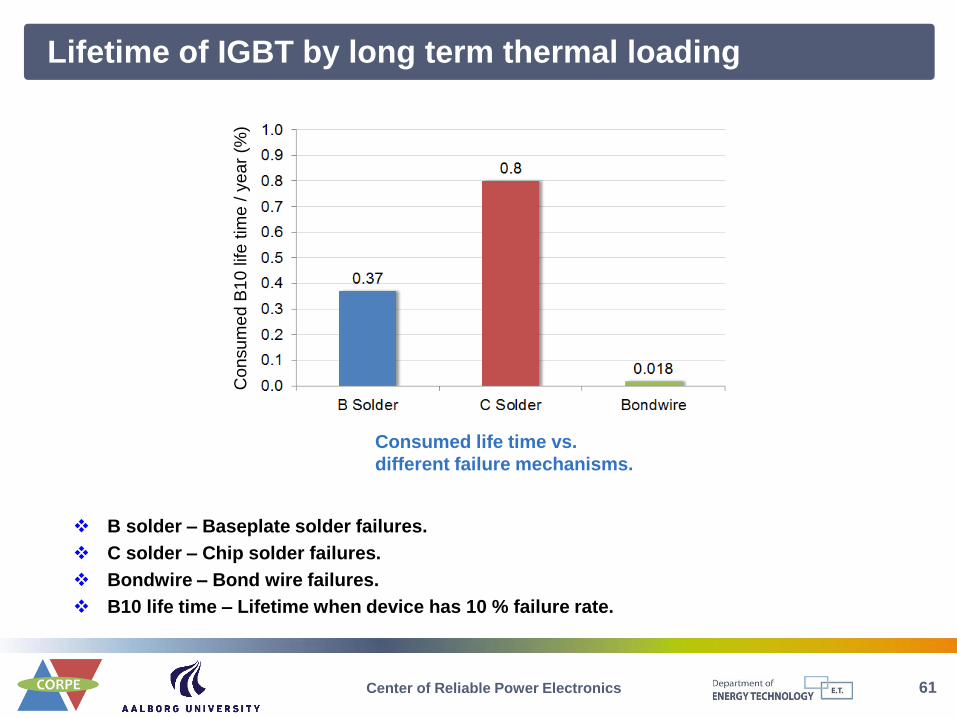
Lifetime of IGBT by long term thermal loading
Consumed life time vs.
different failure mechanisms.
Co
nsu
me
d B
10
life
tim
e / y
ea
r (%
)
B solder – Baseplate solder failures.
C solder – Chip solder failures.
Bondwire – Bond wire failures.
B10 life time – Lifetime when device has 10 % failure rate.

62 Center of Reliable Power Electronics
Summary of lifetime estimation in different time scales
0.0
0.5
1.0
1.5
2.0
2.5
3.0
B Solder C Solder Bondwire
Medium term
Long term
Co
nsu
me
d B
10
life
tim
e (
%)
Wind speed (m/s)
Co
nsu
me
d B
10
life
tim
e (
%)
Consumed life time vs.
different wind speeds.
Consumed life time vs.
different failure mechanisms.
Summary
63 Center of Reliable Power Electronics
► A solution for the long term future in society
► Cost of Energy should be further reduced
► Increased power production close to the consumption place
► Coordinated control of production and consumption
► Future grid configurations may be different – but intelligent
► Systems should be able to run in on-grid and off-grid modes
► PV-plants will get same specifications as wind turbines
► Wind turbines have been the fastest growing in MW but PV will come
► Wind turbine technology – better performance
- Full scale power electronics
- New generator concepts (e.g. PM, gearless)
- Larger size – lower cost per kWh
- Reliability – a key to lower cost of Energy
Power Electronics for renewable energy :
Wind Turbines and Photovoltaic Systems

64 Center of Reliable Power Electronics
► A solution for the long term future in society
► Smart grid pushed by renewable
► Increased power production close to the consumption place
► Coordinated control of production and consumption
► Future grid configurations may be different – but intelligent
► Systems should be able to run in on-grid and off-grid modes
► PV-plants will get same specifications as wind turbines
► Wind turbines have been the fastest growing but PV will come
► Wind turbine technology – better performance
- Full scale power electronics
- New generator concepts (e.g. PM, gearless)
- Larger size – lower cost per kWh
► A university-industry collaborated center has been established to advance
the research progress in reliability of power electronic, especially for the
applications in renewable energy systems.
Power Electronics
enabling renewable energy into an intelligent grid
65 Center of Reliable Power Electronics
References 1. H. Wang, M. Liserre, and F. Blaabjerg, “Toward reliable power electronics - challenges, design tools and opportunities,” IEEE Industrial
Electronics Magazine, Jun. 2013 (in press).
2. H. Wang, F. Blaabjerg, and K. Ma, “Design for reliability of power electronic systems,” in Proceedings of the Annual Conference of the IEEE
Industrial Electronics Society (IECON), 2012, pp. 33-44.
3. F. Blaabjerg, Z. Chen, and S. B. Kjaer, “Power electronics as efficient interface in dispersed power generation systems,” IEEE Trans. on Power
Electron., vol. 19, no. 4, pp. 1184-1194, Sep. 2004.
4. F. Blaabjerg, M. Liserre, and K. Ma, “Power electronics converters for wind turbine systems,” IEEE Trans. on Ind. Appl., vol.48, no.2, pp.708-
719, Mar-Apr. 2012.
5. S. B. Kjaer, J. K. Pedersen, and F. Blaabjerg, “A review of single-phase grid connected inverters for photovoltaic modules,” IEEE Trans. on Ind.
Appl., vol. 41, no. 5, pp. 1292-1306, Sep. 2005.
6. K. Ma, F. Blaabjerg, and M. Liserre, “Thermal analysis of multilevel grid side converters for 10 MW wind turbines under low voltage ride
through”, IEEE Trans. Ind. Appl., vol. 49, no. 2, pp. 909-921, Mar./Apr. 2013.
7. K. Ma, M. Liserre, and F. Blaabjerg, “Reactive power influence on the thermal cycling of multi-MW wind power inverter”, IEEE Trans. on Ind.
Appl., vol. 49, no. 2, pp. 922-930, Mar./Apr. 2013.
8. C. Busca, R. Teodorescu, F. Blaabjerg, S. Munk-Nielsen, L. Helle, T. Abeyasekera, and P. Rodriguez, “An overview of the reliability prediction
related aspects of high power IGBTs in wind power applications,” Journal of Microelectronics Reliability, vol. 51, no. 9-11, pp. 1903-1907, 2011.
9. E. Koutroulis and F. Blaabjerg, “Design optimization of transformerless grid-connected PV inverters including reliability,” IEEE Trans. on Power
Electronics, vol. 28, no. 1, pp. 325-335, Jan. 2013.
10. K. B. Pedersen and K. Pedersen, “Bond wire lift-off in IGBT modules due to thermo-mechanical induced stress,” in Proc. of PEDG’ 2012, pp.
519 - 526, 2012.
11. S. Yang, D. Xiang, A. Bryant, P. Mawby, L. Ran and P. Tavner, “Condition monitoring for device reliability in power electronic converters: a
review,” IEEE Trans. Power Electron., vol. 25, no. 11, pp. 2734-2752, Nov., 2010.
12. M. Pecht and J. Gu, “Physics-of-failure-based prognostics for electronic products,” Trans. of the Institute of Measurement and Control , vol. 31,
no. 3-4, pp. 309-322, Mar./Apr., 2009.
13. Moore, L. M. and H. N. Post, “Five years of operating experience at a large, utility-scale photovoltaic generating plant,” Progress in
Photovoltaics: Research and Applications 16(3): 249-259, 2008.
14. Reliawind, Report on Wind Turbine Reliability Profiles – Field Data Reliability Analysis, 2011.
15. D. L. Blackburn, “Temperature measurements of semiconductor devices - a review,” in Proc. IEEE Semiconductor Thermal Measurement and
Management Symposium, pp. 70-80, 2004.
16. Avenas, Y., L. Dupont and Z. Kahatir, “Temperature measurement of power semiconductor devices by thermo-sensitive electrical parameters -
A review,” IEEE Trans. Power Electron., vol. 27, no. 6, pp. 3081-3092, Jun., 2010.
17. K. Kriegel, A. Melkonyan, M. Galek, and J. Rackles, “Power module with solid state circuit breakers for fault-tolerant applications,” in Proc. of
Integrated Power Electronics Systems (CIPS), pp. 1-6, 2010.
18. ZVEL, Handbook for robustness validation of automotive electrical/electronic modules, Jun. 2008.
66 Center of Reliable Power Electronics
References
1. K. Ma, F. Blaabjerg, “Loss and thermal redistributed modulation methods for three-level neutral-point-clamped wind power inverter undergoing
Low Voltage Ride Through”, IEEE Trans. on Industrial Electronics, 2013. (Also in Proc. of ISIE’ 2012, pp. 1880-1887, 2012).
2. K. Ma, F. Blaabjerg, “Thermal Optimized Modulation Method of Three-level NPC Inverter for 10 MW Wind Turbines under Low Voltage Ride
Through,” IET Journal on Power Electronics, vol. 5, no. 6, pp. 920-927, 2012.
3. K. Ma, F. Blaabjerg, M. Liserre, “Operation and Thermal Loading of Three-level Neutral-Point-Clamped Wind Power Converter under Various
Grid Faults,” IEEE Trans. on Industry Applications, 2013.
4. K. Ma, M. Liserre, F. Blaabjerg, “Reactive Power Influence on the Thermal Cycling of Multi-MW Wind Power Inverter,” IEEE Trans. on Industry
Applications, vol. 49, no. 2, pp. 922-930, 2013. (Also in Proc. of APEC’ 2012, pp. 262-269, 2012.)
5. A. Isidori, F.M. Rossi, F. Blaabjerg, K. Ma, “Thermal Loading and Reliability of 10 MW Multilevel Wind Power Converter at Different Wind
Roughness Classes,” IEEE Trans. on Industry Applications, 2013.
6. K. Ma, F. Blaabjerg, M. Liserre, “Electro-thermal model of power semiconductors dedicated for both case and junction temperature estimation,”
Proc. of PCIM’ 2013, 2013.
7. K. Ma, F. Blaabjerg, “Reliability-Cost Models for the Power Switching Devices of Wind Power Converters,” Proc. of PEDG’ 2012, pp.820-827,
2012.
8. K. Ma, M. Liserre, F. Blaabjerg, “Lifetime Estimation for the Power Semiconductors Considering Mission Profiles in Wind Power Converter,” in
Proc. of ECCE’ 2013, 2013 (in press).
9. F. Blaabjerg, M. Liserre, K. Ma, “Power Electronics Converters for Wind Turbine Systems,” IEEE Trans. on Industry Applications, vol. 48, no. 2,
pp. 708-719, 2012.
10. K. Ma, F. Blaabjerg, “The Impact of Power Switching Devices on the Thermal Performance of a 10 MW Wind Power NPC
Converter,” Energies 5, no. 7: 2559-2577, 2012.