power distribution control coordinating ultracapacitors
TRANSCRIPT
ACC ‘04
1
Abstract— Electrical energy storage is a central element to any
electric-drivetrain technology – whether hybrid-electric, fuel-cell, or all-electric. A particularly cost-sensitive issue with energy storage is the high replacement cost of depleted battery banks. One possibility to ease the power burden on batteries and fuel cells is to use ultra-capacitors as load-leveling devices. The high power density of ultra-capacitors allows a significant reduction in the power fluctuations imposed on the remaining electrical system; however, the same ultra-capacitors have a very low energy density and therefore must be used sparingly and with coordination. A control strategy for coordinated power distribution is a central issue for ultracapacitor-supported systems. Toward this end, several control methods are implemented on an electric vehicle equipped with a battery/ultracapacitor system with the goal of improving battery life and overall vehicle efficiency. A particular goal is to obtain both a peaking load control and a frequency-weighted coordination between capacitor and battery in order to mitigate transients in the battery current demand. A key control design issue is that the control objectives vary with respect to vehicle velocity, driver’s power demand, and state-of-charge of both the batteries and ultracapacitors.
Index Terms—Ultracapacitor, hybrid-electric vehicle, control.
I. INTRODUCTION HIS work is a continuation of a recent project conducted at the Pennsylvania Transportation Institute at
Pennsylvania State University in which ultra-capacitors are used in conjunction with batteries as an energy storage system for mass-transit vehicles [1].
As part of this prior work, the properties of the ultra-capacitors were extensively characterized and the modeling results were used to develop an ultra-capacitor energy storage
This work was supported in part by the Mid Atlantic Regional Consortium
for Advanced Vehicles (MARCAV) and the Department of Transportation under Grant DTRS56-99-T-0016.
E. Ozatay and Ben Zile are graduate students in the Mechanical and Nuclear Engineering department at Pennsylvania State University.
J. Anstrom is a Research Faculty with the Pennsylvania Transportation Institute,.
S. Brennan (corresponding author) is an Assistant Professor of Mechanical and Nuclear Engineering with a joint appointment with the Pennsylvania Transportation Institute, 318 Leonhard Building, University Park, PA 16802 . phone: 814-863-2430; fax 814-865-9693 (e-mail: [email protected]).
system model in the Department of Energy’s Powertrain System Analysis Toolkit (PSAT) hybrid vehicle modeling environment. Using this PSAT simulation, the influence of the ultra-capacitor storage system were examined in both an electric and hybrid electric mass transit vehicle. These simulations were validated with experimental data taken from both an electric transit bus (without an ultra-capacitor energy storage system), provided by the Chattanooga Area Regional Transit Authority (CARTA), and on a hybrid electric passenger vehicle, the Penn State Electric Lion, both with and without the ultra-capacitor energy storage system. The results of the project show a significant reduction in peak currents experienced by the battery pack in drive cycles with a high number of starts and stops, such as the Manhattan drive cycle.
The benefits of the ultracapacitor system were greatly affected not only by the capacity of the ultracapacitors, but also by the energy management controller. At the completion of the project, it was concluded that additional focus on this energy management controller is required in order to achieve optimization of both the power cycle efficiency of ultracapacitor energy storage system and of the battery life.
Similar ultracapacitor systems are in development elsewhere. Nova Bus Corporation, Quebec, has been testing a bus powered by a zinc-air battery pack [2] with a goal of supplementing the power system with ultracapacitors. Henry Brandhorst and Zheng Chen of Auburn University, Alabama are currently developing a system that uses an ultra-capacitor to improve the power capabilities of a battery-powered system [3]. The results of their tests showed that the addition of the ultra-capacitor increased the power level by 40% over the battery-only system. Solectria Corporation is currently developing a high power DC-to-DC converter for ultra-capacitors [4]. This ultra-capacitor system was tested on an electric vehicle – the range of the vehicle was increased 32 % and the energy consumption remained unchanged. Xinxiang Yan and Dean Patterson of Northern Territory University, Australia have also researched ways to utilize ultra-capacitors in electric vehicle applications [5]. Their system uses an ultra-capacitor bank to complement a zinc-bromine battery; again the goal is to increase the range and performance of electric vehicles without increasing cost. General Electric Company has developed an ultra-capacitor/battery system to
Power Distribution Control Coordinating Ultracapacitors and Batteries for Electric
Vehicles Evren Ozatay, Ben Zile*, Joel Anstrom and Sean Brennan*,
*Member, IEEE
T
ACC ‘04
2
be used on either electric vehicles or hybrid electric vehicles [6], with a specific intention of being used on a hybrid electric transit bus. Honda has recently come out with a fuel-cell powered vehicle that uses ultracapacitors for electrical energy storage. The vehicle’s powertrain is capable of producing 80hp, can travel at speeds up to 93mph and for distances of up to 220 miles, and carries up to 3.75kg of hydrogen [7].
The remainder of the paper is summarized as follows: Section 2 introduces the dynamic model of the ultracapacitor system. Section 3 discusses peaking power control strategies and experimental results, focusing on the challenges associated with the ultracapacitor power distribution. Section 4 introduces a frequency-domain control strategy with the goal of generating a frequency-based allocation of power between the battery and capacitor system. Finally, a conclusions section then summarizes the main research findings.
II. DYNAMIC MODEL OF THE ULTRACAPACITOR The goal of any multi-mode power storage system is to gain
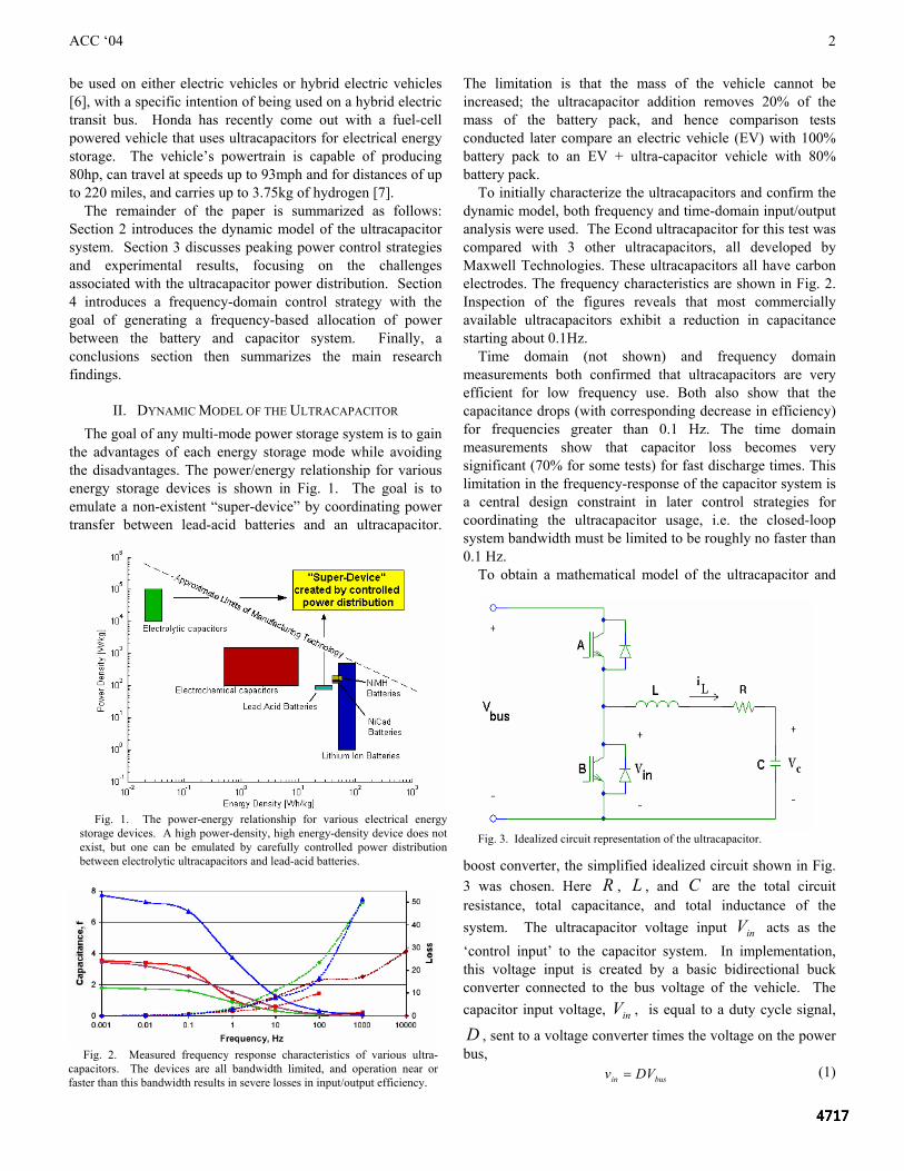
the advantages of each energy storage mode while avoiding the disadvantages. The power/energy relationship for various energy storage devices is shown in Fig. 1. The goal is to emulate a non-existent “super-device” by coordinating power transfer between lead-acid batteries and an ultracapacitor.
The limitation is that the mass of the vehicle cannot be increased; the ultracapacitor addition removes 20% of the mass of the battery pack, and hence comparison tests conducted later compare an electric vehicle (EV) with 100% battery pack to an EV + ultra-capacitor vehicle with 80% battery pack.
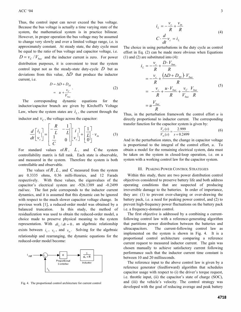
To initially characterize the ultracapacitors and confirm the dynamic model, both frequency and time-domain input/output analysis were used. The Econd ultracapacitor for this test was compared with 3 other ultracapacitors, all developed by Maxwell Technologies. These ultracapacitors all have carbon electrodes. The frequency characteristics are shown in Fig. 2. Inspection of the figures reveals that most commercially available ultracapacitors exhibit a reduction in capacitance starting about 0.1Hz.
Time domain (not shown) and frequency domain measurements both confirmed that ultracapacitors are very efficient for low frequency use. Both also show that the capacitance drops (with corresponding decrease in efficiency) for frequencies greater than 0.1 Hz. The time domain measurements show that capacitor loss becomes very significant (70% for some tests) for fast discharge times. This limitation in the frequency-response of the capacitor system is a central design constraint in later control strategies for coordinating the ultracapacitor usage, i.e. the closed-loop system bandwidth must be limited to be roughly no faster than 0.1 Hz.
To obtain a mathematical model of the ultracapacitor and
boost converter, the simplified idealized circuit shown in Fig. 3 was chosen. Here R , L , and C are the total circuit resistance, total capacitance, and total inductance of the system. The ultracapacitor voltage input inV acts as the ‘control input’ to the capacitor system. In implementation, this voltage input is created by a basic bidirectional buck converter connected to the bus voltage of the vehicle. The capacitor input voltage, inV , is equal to a duty cycle signal,
D , sent to a voltage converter times the voltage on the power bus, busin DVv = (1)
Fig. 3. Idealized circuit representation of the ultracapacitor.
Fig. 1. The power-energy relationship for various electrical energy storage devices. A high power-density, high energy-density device does not exist, but one can be emulated by carefully controlled power distribution between electrolytic ultracapacitors and lead-acid batteries.
Fig. 2. Measured frequency response characteristics of various ultra-capacitors. The devices are all bandwidth limited, and operation near or faster than this bandwidth results in severe losses in input/output efficiency.
ACC ‘04
3
Thus, the control input can never exceed the bus voltage. Because the bus voltage is actually a time varying state of the system, the mathematical system is in practice bilinear. However, in proper operation the bus voltage may be assumed to change very slowly and over a limited voltage range, i.e. is approximately constant. At steady state, the duty cycle must be equal to the ratio of bus voltage and capacitor voltage, i.e.
busC VvD /= and the inductor current is zero. For power distribution purposes, it is convenient to treat the system control input not as the steady-state duty-cycle D but as deviations from this value, D∆ that produce the inductor current, i.e.
bus
C
SS
Vv
u
DDD
+=
+∆=. (2)
The corresponding dynamic equations for the inductor/capacitor branch are given by Kirchoff's Voltage Law, where the system states are Li , the current through the
inductor and Cv , the voltage across the capacitor:
incc
L vLvi
C
LLR
vi
dtd
⋅⎥⎥
⎦
⎤
⎢⎢
⎣
⎡+⎥
⎦
⎤⎢⎣
⎡
⎥⎥⎥
⎦
⎤
⎢⎢⎢
⎣
⎡ −−=⎥
⎦
⎤⎢⎣
⎡
0
1
01
1
(3)
For standard values of R , L , and C the system controllability matrix is full rank. Each state is observable, and measured in the system. Therefore the system is both controllable and observable.
The values of R , L , and C measured from the system are 0.3335 ohms, 0.36 milli-Henries, and 12 Farads respectively. With these values, the eigenvalues of the capacitor’s electrical system are -926.1389 and -0.2499 rad/sec. The fast pole corresponds to the inductor current dynamics, and it is assumed that this dynamic can be ignored with respect to the much slower capacitor voltage change. In previous work [1], a reduced-order model was obtained by a balanced truncation. In this study, the method of residualization was used to obtain the reduced-order model, a choice made to preserve physical meaning to the system representation. With 0/ =dtdiL , an algebraic relationship exists between Li , Cv , and inv . Solving for the algebraic relationship and rearranging, the dynamic equations for the reduced-order model become:
Lc
incL
ivdtdC
Rv
Rv
i
=⋅
+−= (4)
The choice in using perturbations in the duty cycle as control effort in Eq. (2) can be made more obvious when Equations (1) and (2) are substituted into (4):
( )
RV
u
RV
Vv
RVu
Rv
RVDD
Rv
RVD
Rv
i
bus
bus
bus
Cbusc
busSSc
buscL
=
+⋅
+−=
⋅+∆+−=
⋅+−=
(5)
Thus, in the perturbation framework the control effort u is directly proportional to inductor current. The corresponding transfer function for the capacitor system is given by:
2499.0999.2
)()(
+=
ssVsV
in
C (6)
And in the perturbation states, the change in capacitor voltage is proportional to the integral of the control effort, u. To obtain a model for the remaining electrical system, data must be taken on the system in closed-loop operation, i.e. on a system with a working control law for the capacitor system.
III. PEAKING POWER CONTROL STRATEGIES Within this study, there are two power distribution control
objectives considered to preserve battery life and both address operating conditions that are suspected of producing irreversible damage to the batteries. In order of importance, they are: (1) to prevent over-charging or over-drawing the battery pack, i.e. a need for peaking power control, and (2) to prevent high-frequency power fluctuations on the battery pack i.e. a frequency-domain control.
The first objective is addressed by a combining a current-following control law with a reference-generating algorithm that partitions power distribution between the batteries and ultracapacitors. The current-following control law as implemented on the system is shown in Fig. 4. It is a proportional control architecture comparing a reference current request to measured inductor current. The gain was chosen manually to achieve satisfactory current following performance such that the inductor current time constant is between 10 and 20 milliseconds.
The reference input to the above control law is given by a reference generator (feedforward) algorithm that schedules capacitor usage with respect to (i) the driver’s torque request, i.e. throttle input, (ii) the capacitor’s state of charge (SOC), and (iii) the vehicle’s velocity. The control strategy was developed with the goal of reducing average and peak battery
Fig. 4. The proportional control architecture for current control
ACC ‘04
4
currents over a wide variety of driving cycles, and was developed and tuned by iterative testing on the demonstrator vehicle.
The reference current demanded from the capacitor system,
refI , is primarily determined by a calculated estimate of the
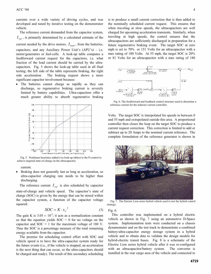
current needed by the drive motors, loadI , from the batteries, capacitors, and any Auxiliary Power Unit’s (APU’s) – i.e. motor/generators or fuel-cells. A look-up table computes a feedforward current request for the capacitors, i.e. what fraction of the load current should be carried by the ultra-capacitors. Fig. 5 shows the look-up table used in all final testing; the left side of the table represents braking, the right side acceleration. The braking request shows a more significant capacitor involvement because: • The batteries cannot charge as rapidly as they can
discharge, so regenerative braking current is severely limited by battery capabilities. Ultra-capacitors offer a much greater ability to absorb regenerative braking
current. • Braking does not generally last as long as acceleration, so
ultra-capacitor charging rate needs to be higher than discharging.
The reference current refI is also scheduled by capacitor
state-of-charge and vehicle speed. The capacitor’s state of charge (SOC) is given by the energy that can be stored within the capacitor system, a function of the capacitor voltage squared:
2CvKSOC ⋅= (3)
The gain K is 3.05 × 10⁻⁵; it acts as a normalization constant so that the equation yields SOC = 0 for no voltage on the capacitor and SOC = 1 for the maximum voltage of 180 V. Thus the SOC is a percentage measure of the total remaining energy available from the capacitor.
The premise for scheduling control effort with SOC and vehicle speed is to have the ultra-capacitor system ready for the future events (i.e., if the vehicle is stopped, an acceleration is the next thing that can occur, so the ultra-capacitors should be charged and ready). The result of this secondary scheduling
is to produce a small current correction that is then added to the nominally scheduled current request. This ensures that when traveling at slow speeds, the ultracapacitors are well charged for upcoming acceleration transients. Similarly, when traveling at high speeds, the control ensures that the ultracapacitors are sufficiently discharged in preparation for a future regenerative braking event. The target SOC at zero mph is set to 70% or 151 Volts for an ultracapacitor with a max rating of 180 Volts. At 55 mph, the target SOC is 20% or 81 Volts for an ultracapacitor with a max rating of 180
Volts. The target SOC is interpolated for speeds in between 0 and 55 mph and extrapolated outside this area. A proportional controller then closes the loop on the target SOC to produce a current request correction. This correction is limited to add or subtract up to 20 Amps to the nominal current reference. The complete formulation of the reference generator is shown in
Fig. 6. This controller was implemented on a hybrid electric
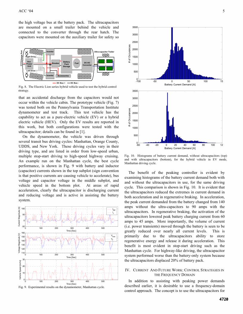
vehicle as shown in Fig. 7 using an automotive D-Space system. Implementation tests were conducted on a chassis dynamometer and on the test track to demonstrate a combined battery/ultra-capacitor energy storage system in a hybrid vehicle and to obtain data to validate the design models for hybrid-electric transit buses. Fig. 8 is a schematic of the Electric Lion series hybrid vehicle after it was re-configured with an ultracapacitor/battery system. The converter is installed in the rear cargo area of the vehicle and connected to
Fig. 5. Nonlinear heuristics added (via look-up tables) to the P-control to
achieve targeted state-of-charge on the ultracapacitor.
Fig. 6. The feedforward and feedback control structure used to determine a
reference current for the inductor current controller.
Fig. 7. The Electric Lion series hybrid vehicle used to test the hybrid control
strategy.
ACC ‘04
5
the high voltage bus at the battery pack. The ultracapacitors are mounted on a small trailer behind the vehicle and connected to the converter through the rear hatch. The capacitors were mounted on the auxiliary trailer for safety so
that an accidental discharge from the capacitors would not occur within the vehicle cabin. The prototype vehicle (Fig. 7) was tested both on the Pennsylvania Transportation Institute dynamometer and test track. This test vehicle has the capability to act as a pure-electric vehicle (EV) or a hybrid electric vehicle (HEV). Only the EV results are reported in this work, but both configurations were tested with the ultracapacitor; details can be found in [1].
On the dynamometer, the vehicle was driven through several transit bus driving cycles: Manhattan, Orange County, UDDS, and New York. These driving cycles vary in their driving type, and are listed in order from low-speed urban, multiple stop-start driving to high-speed highway cruising. An example run on the Manhattan cycle, the best cycle performance, is shown in Fig. 9 with battery and inductor (capacitor) currents shown in the top subplot (sign convention is that positive currents are causing vehicle to accelerate), bus voltage and capacitor voltage in the middle subplot, and vehicle speed in the bottom plot. At areas of rapid acceleration, clearly the ultracapacitor is discharging current and reducing voltage and is active in assisting the battery system.
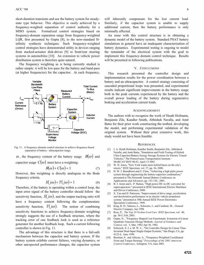
The benefit of the peaking controller is evident by examining histograms of the battery current demand both with and without the ultracapacitors in use, for the same driving cycle. This comparison is shown in Fig. 10. It is evident that the ultracapacitors reduced the extremes in current demand in both acceleration and in regenerative braking. In acceleration, the peak current demanded from the battery changed from 140 amps without the ultra-capacitors to 90 amps with the ultracapacitors. In regenerative braking, the activation of the ultracapacitors lowered peak battery charging current from 60 amps to 45 amps. More importantly, the volume of current (i.e. power transients) moved through the battery is seen to be greatly reduced over nearly all current levels. This is primarily due to the ultracapacitors ability to store regenerative energy and release it during acceleration. This benefit is most evident in stop-start driving such as the Manhattan cycle. For highway-like driving, the ultracapacitor system performed worse than the battery-only system because the ultracapacitors displaced 20% of battery pack.
IV. CURRENT AND FUTURE WORK: CONTROL STRATEGIES IN THE FREQUENCY DOMAIN
In addition to assisting with peaking power demands described earlier, it is desirable to use a frequency-domain control approach. The concept is to use the ultracapacitors for
Inverter
Inverter
Right Drive
Left Drive
BatteryPack
Storage
Aux.PowerUnit
Fuel DC-DCConverter
Breaker
Accessories
Cha
rge
Port
DC Bus + DC Bus -
Ultra-capacitor Trailer
Fig. 8. The Electric Lion series hybrid vehicle used to test the hybrid control strategy.
0 100 200 300 400 500-50
0
50
100
Time [Sec]
Cur
rent
Mag
nitu
de [A
]
0 100 200 300 400 500110
120
130
140
150
160
Time [Sec]
Vol
tage
Mag
nitu
de [V
]
0 100 200 300 400 5000
10
20
30
Time [Sec]
Veh
icle
Spe
ed [m
i/hr]
IbatiL
VbusvC
Fig. 9. Experimental results on the dynamometer, Manhattan cycle.
-100 -50 0 50 100 1500
500
1000
1500
2000
2500
3000
3500
Battery Current Demand [A]
# of
Occ
uran
ces
-60 -40 -20 0 20 40 60 80 100 1200
500
1000
1500
2000
2500
3000
3500
Battery Current Demand [A]
# of
Occ
uran
ces
Fig. 10. Histograms of battery current demand, without ultracapacitors (top) and with ultracapacitors (bottom), for the hybrid vehicle in EV mode, Manhattan driving cycle.
ACC ‘04
6
short-duration transients and use the battery system for steady-state type behavior. This objective is easily achieved by a frequency-weighted separation of control authority for a MISO system. Formalized control strategies based on frequency-domain separation range from frequency-weighted LQR, first presented by Gupta [8], to the now-standard H-infinity synthesis techniques. Such frequency-weighted control strategies have demonstrated utility in devices ranging from stacked-actuator disk-drives [9] to front/rear steering systems in automobiles [10]. An extension to vehicle power distribution system is therefore quite natural.
The frequency weighting as is being currently studied is rather simple: it will be low-pass for the battery and band-pass (at higher frequencies) for the capacitor. At each frequency,
ω , the frequency content of the battery usage ( )ωB and
capacitor usage ( )ωC must have a weighting:
( ) ( ) 1=+ ωω CB (7) However, this weighting is directly analogous to the Bode frequency criteria. ( ) ( ) 1=+ ωω jTjS (8) Therefore, if the battery is operating within a control loop, the input error signal of the battery controller should follow the sensitivity function, ( )ωjS , and the output tracking ratio will have a frequency content following the complementary sensitivity function, ( )ωjT . The notion of combining sensitivity functions to achieve frequency-domain weighting strongly suggests the use of a feedback structure, where the tracking error of one feedback look is used as a reference generator for another feedback loop. Such a current following controller is shown in Fig. 11. The advantage of this structure is that there is a fail-safe mechanism between the capacitor and battery system. If the battery system exhibits current failures, varying dynamics, or other unexpected performance changes, the capacitor system
will inherently compensate for the lost current load. Similarly, if the capacitor system is unable to supply additional current, then the battery performance is only minimally affected. An issue with this control structure is in obtaining a dynamic model of the battery system. Standard PSAT battery simulations in general have an inadequate characterization of battery dynamics. Experimental testing is ongoing to model the remainder of the electrical system with the goal to implement this frequency-domain control technique. Results will be presented in following publications.
V. CONCLUSIONS This research presented the controller design and
implementation results for the power coordination between a battery and an ultracapacitor. A control strategy consisting of cascaded proportional loops was presented, and experimental results indicate significant improvements in the battery usage both in the peak currents experienced by the battery and the overall power loading of the battery during regenerative braking and acceleration current loads.
ACKNOWLEDGMENT The authors with to recognize the work of Heath Hofmann,
Benjamin Zile, Kandler Smith, Abhishek Neralla, and Amit Batra for their prior work constructing the testbed, developing the model, and performing experimental validation of the original system. Without their prior extensive work, this study would not have been feasible.
REFERENCES [1] J. A. Heath Hofmann, Kandler Smith, Benjamin Zile, Abhisheck
Neralla, and Amit Batra, "Simulation and Field-Testing of Hybrid Ultra-Capacitor/Battery Energy Storage Systems for Electric Transit Vehicles," The Pennsylvania Transportation Institute - MARCAV/DOT 00-01, April 15 2003.
[2] W. D. Jones, "New York wants more hybrid buses on the city's streets," IEEE Spectrum, vol. 37, pp. 36, 2000.
[3] H. W. J. Brandhorst and Z. Chen, "Achieving a high pulse power system through engineering the battery-capacitor combination," presented at The Sixteenth Annual Battery Conference on Applications and Advances, pp. 153-156., 2001.
[4] B. J. Arnet and L. P. Haines, "High power DC-to-DC converter for supercapacitors," presented at IEEE International Electric Machines and Drives Conference, 2000.
[5] X. Yan and D. Patterson, "Improvement of drive range, acceleration and deceleration performance in an electric vehicle propulsion system," presented at 30th Annual IEEE Power Electronics Specialists Conference, 1999.
[6] King, R. D., Salasoo, L., Schwartz, J., and Cardinal, M., General Electric Company, Jun 1998.
[7] Ross, P., The Top 10 Techno-Cool Cars IEEE Spectrum, vol. 40, pp. 30-5, Feb, 2003.
[8] Gupta, N., "Frequency Shaped Cost Functionals: Extension of Linear Quadratic Guassian Design Methods Journal of Guidance and Control, vol. 3, Mar, 1982-Apr 30, 1982.
[9] Schroeck, S. J. a. M. W. C., "On Controller Design for Linear Time-Invariant Dual-Input Single-Output Systems," San Diego, CA, pp. 4122-6, June 1999.
[10] Brennan, S. and Alleyne, A., "Frequency-Weighted Coordinated Front and Torque Steering," Proceedings of the 2001 American Control Conference, Arlington, VA, June 2001.
VariableBandwidthLow-Pass
Filters MeasuredBattery Current +
+
InductorCurrent
Total CurrentTo Bus(Motor)
reqiCurrent Reference(Driver)
busi
-
+
BatterySystem
CapacitorSystem
SupervisoryVoltage Monitor
CapacitorVoltage (SOC)
?
~ 0.1 Hz
~ 1 Hz
VariableBandwidthLow-Pass
Filters MeasuredBattery Current +
+
InductorCurrent
Total CurrentTo Bus(Motor)
reqiCurrent Reference(Driver)
busi
-
+
BatterySystem
CapacitorSystem
SupervisoryVoltage Monitor
CapacitorVoltage (SOC)
?
~ 0.1 Hz
~ 1 Hz
Fig. 11. A frequency-domain control structure to achieve frequency-based
separation of battery / ultracapacitor usage.