· density powders. cu is the primary mental produced. ... commonly used explosives are ... the...
TRANSCRIPT

www.uptunotes.com
MANUFACTURING SCIENCE-I
UNIT-4
POWDER METALLURGY
POWDER METALLURGY The powder metallurgy process consists of mixing elemental or alloy powder, compacting the mixture in a die and then sintering or heating the resultant shape in a controlled atmosphere. Powder metallurgy is a highly developed method of manufacturing ferrous and nonferrous materials. It is a chip less working process. This process is cost effective in producing simple or complex part in manufacturing (Production) rates which can range from a few hundreds to several thousands parts per hour. Due to high cost of die and equipment this process is suitable for mass production only. The basic steps involved in the production process are given below.
• Preparation of powder or powders of desired composition. • Mixing and blending – Powder are mixed thoroughly and blended to ensure desired property. • Compacting the powders into desired shape and size and providing strength to the parts. • Sintering – Green compacts are heated at elevated temperature to impart strength.
ADVANTAGE OF POWDER METALLURGY
• Parts with closed dimensional tolerance (nearest shape) and good surface finish can be produced. • It eliminate or minimizes scrap losses by more than 97% of the raw material in the finished part, unlike other
process. • Process can be fully automated hence unskilled labour can be employed which reduces labour cost. • It eliminate or minimizes machining. • It facilitates manufacture of certain parts by mixing different metals, metals and non metals, metals and
ceremics ect to obtain desired properties which is impossible with other working processes. • High production rates from 500-1000 parts/hour can be achieved. • It facilitates manufactures of small and unique shape part which cannot be produce by any other manufacturing
process. • Detect free component with uniform structure can produce. • Non equilibrium composition possible e.g. cr. alloys.
LIMITATIONS OF POWDER METALLURGY
• The cost of material in powder form is quite high this cost is offset for Large volume production by absence of scrap and low labour cost.
• Products with intricate design are difficult to produce as there is little flow of metal powder during compaction.
• The residual porosity left in sintered parts makes then rough. • This process is economically feasible for Large volume production due to high cost of dies and equipments. • Producing parts of Large size and weight is quite expensive due to costly dies. • It is difficult to compress some metal powders and also difficult to procure some metal powders. • The density of compact is not uniform throughout. • Some e.g. zr present explosion hazard. • Parts produce by powder metallurgy have low impact and fatigue strength as compared to other method. • Healt problems from atmospheric contamination of the work place.
APPLICATION OF POWDER METALLURGY
The application of powder metallurgy components fall in two main groups- First are component that are difficult to manufacture by other method such as those made from tungsten,
Molybdenum and tungsten carbide.
N o t e s B y : A N I M E S H P A L E m a i l : a n i m e s h 1 4 @ g m a i l . c o m
Page 1

www.uptunotes.com
The second group consists of components that offer a cost effective alternatives to machined components, casting and forging.
Some applications are as follows- • Used to produce porous parts e.g filters. • Some components of tungsten employed in jet engines are made by powder metallurgy. • Auto mobile components such as clutch plates, connecting rods, cam shafts and piston rings etc. • Many types of hard and soft magnetic components. • Grinding wheels are manufactured by using steel and diamond powder. • Nozzle for rockets and missiles are made using silver infiltrated tungsten. • It is used to produce complex shaped parts which require machining when produced by other methods e.g. gears. • Electrical bushes for motors are made by combining metallic and non metallic material. • Some parts used in clocks, type writers, calculators, permanent magnet etc. are made by powder metallurgy
process.
PRODUCTION OF METAL POWDER Some common methods used in powder production depending on type and nature of metals are as follows. 1. Atomization
In this process molten metal is broken up into small droplets by spraying it on the streme of inest gas or air jets and rapidly frozen before the drops come into contact with each other or with the solid surface this technique is applicable to all metals that can be melted and is used commercially for the production of iron, copper, brass, bronze, lead, zinc etc. 2. Crushing and Milling
Crushing and milling operations are perform on brittle or less ductile materials (metals). Metal particles are crushed in crushing m/c for final powder. 3. Electrolysis Process
By choosing suitable conditions such as electrolytic composition and concentration temp and current density many metals can be deposited in a spungy or powdered state further processing is required which yields high purity and high density powders. Cu is the primary mental produced. 4. Chemical Process
The most common chemical powder treatments involve oxide reduction precipitate form solution and thermal decomposition. The powder produced can have a great variation in properties and yet have closely controlled particle size and shape. CHARACTERISTICS OF METAL POWDERS Some characteristics on which behaviour of metal powder depends are described below- 1. Particle shape & size distribution
The shape of particles depends mainly on the method of production of powders, spheroidal shaped particles have excellent sintering property and irregular shaped particles are good for moulding. Mostly 100 μ size powders are used. 2. Density
True density is mass per unit volume of the solid material apparent density is defined as the mass of loose powder per unit actual volume filled by the powder it depends on particle shape, size distribution powders with high apparent density require shorter compressive strike to produce a compact of given density and size. 3. Flow Rate
It is defined as the time required for a measured quantity of powder to flow out of a standard orifice flow rate should be high to obtain high production rate. 4. Compressibility and Compression Ratio
N o t e s B y : A N I M E S H P A L E m a i l : a n i m e s h 1 4 @ g m a i l . c o m
Page 2

www.uptunotes.com
Both depends upon shape size and size distribution of particles compressibility is defined as the ratio of initial volume of the powder (Un pressed volume) to final volume green strength to powder also known as mechanical strength of compressed part. PROCESSING OF POWDERS Processing of powder has been classified in two groups- (A) PRIMARY PROCESS
1. Mixing and Blending of Powder
Mixing means the intermixing of powders of two or more materials. Intermixing of a powder and binder or intermixing of a powder and lubricants. The mixing and blending of metal powder is done under controlled condition to avoid contamination and deterioration. It fulfil following purposes.
• It produces a uniform distribution of particle shape and size. • It allows different metal to be mixed to obtain specific physical property. • It improves metal powder interaction by addition of lubricants (e.g stearic acid, Zinc stearate in proportion of
0.25 to 0.5% by weight) to the powder improves the flow characteristics of the powder. Such blends result in reduced friction between the metal particles, improved flow of powder metal into dies and longer die life.
• Co-combine metallic and non metallic powder. 2. Compacting or Briquetting
The mixed powders are compacted in die to form the size and shape of the desired part, parts fo produced are known as green compact. The density after compaction is called green density. Depends upon the compaction pressure, dimensions of the compacted parts and powder hardness. The compacting is carried out at room temp. in dies. The die cavity is filled with required amount of mixed powder for uniform distribution of pressure two punches are generally used one from top and other from bottom side of powder. The green compact expand slightly when taken out of die to elastic recovery this expansion depends of the pressure and extend of plastic deformation in powder particles. 3. Pre-Sintering (Not done when machining is not required)
It is defined as a process in which green compact is heated to temperature below final sintering temperature to increase the strength. It also removes the lubricant and binders added during blending. After this the final sintering operation is performed. 4. Sintering
Sintering is the process of heating the material to a temp. below the melting temp. but high enough to allow bonding or fusion of individual particles under protective atmosphere prevent oxidation. Continuous sintering furnace are used which have 3 chambers-
• A chamber to volatize (easily becoming goes or dangerous) the lubricants in the green compact in order to improve bond strength and prevent cracking it. It is called brunt off chamber. It slowly raises the temp. in a controlled manner.
• A high temperature chamber for sintering for bonding b/w the powder particles the time during the second stage must be sufficient to produce the desired density and final properties.
• A cooling chamber. B) SECONDARY OPERATIONS These operation are carried out to obtain desired dimensional tolerances, physical property improve its strength, hardness and wear resistance etc. finishing operations are often perform after sintering for better dimensional accuracy different machining operations are performed. Heat treating the sintered part will improve its hardness, strength and wear resistance. Finishing operation is perform to improve the surface characteristics of part.
N o t e s B y : A N I M E S H P A L E m a i l : a n i m e s h 1 4 @ g m a i l . c o m
Page 3

www.uptunotes.com
UNCONVENTION METAL FORMING PROCESS
Unconventional metal forming process are these which may be use to form materials that connote be formed by using conventional methods metals are formed by the release and application of large amount of energy in a very short interval of time. This makes it possible to form large and difficult parts with less expensive equipment and tools. HERF (HIGH ENERGY RATE FORMING) PROCESS The processes in which the released energy is directly used to form the metals are known as high energy rate forming process. This method is used in explosive forming, electro hydraulic forming. EXPLOSIVE FORMING In the above given figure two schemes of explosive forming is shown. In both the shock wave in the fluid medium (normally water) is generated by detonating an explosive charge for a small part the entire shock wave front is utilized in a confined space, where as for large object only part of the wave is used obviously, the unconfined operation is less efficient. However there is a greater hazard of die failure in the confined operation due to lack of control in explosive forming.
The shock wave induced by the charge detonation instanteuseously converts the water from low temp. And pressure to a high temp and Pressure water. Gas bubbles produce along with shock waves expand spherically and collapse on the surface of water. These shock waves when impinge on w/p. The metal is forced in to the die with high velocity (approx 100m/sec) to give a desired shape air from die is evacuated by vacuum line at the bottom of the die. Most Commonly used explosives are
• Penta Erythriol • Tetranitrate (TENT) • Trinitro Toluene (TNT)
The distance b/w the charge and the metal piece is called standoff distance. The standoff distance and the amount of charge determine the amount of pressure transmitted to the metal small standoff distances are used for deep drawing and large stand offs are used for shallow drawing. The optimum standoff distance for a single point charge is given as
S = diameter (for circular jobs of small dimensions i.e. < 60mm) = O.S.D. (diameter of larger jobs)
With water as the transmitting medium, the peak pressure P obtained by N/mm2
𝑃𝑃 =𝐶𝐶𝑊𝑊𝑛𝑛
3�
𝐷𝐷𝑛𝑛
N o t e s B y : A N I M E S H P A L E m a i l : a n i m e s h 1 4 @ g m a i l . c o m
Page 4
www.uptunotes.com
Where W = Weight of explosive in Newton D = Stand -off distance (mm) N = Constant around (1.15) C = constant of proportionality Values of C is
Pentolite TNT Tetryl C 4500 4320 4280
Applications of explosive forming
• The curved domes of missiles. • Large curved panels of Rockets. • Asymmetrical exhaust tubes for jet engines.
Characteristics of Explosive forming
• Method is suitable for very large sheets with relatively complex shapes. • Low tooling cost but high labour cost. • Suitable for low quantity production. • It does not require any punch or die for redrawing.
ELECTRO HYDRAULIC FORMING
Electric discharge in the form of sports, instead of explosives, can also be used to generate a shock wave in a fluid. An operation using this principle of generating a shock wave is called electro hydraulic forming. The characteristics of this process are very similar to those of explosive forming figure shows the basic scheme of electro hydraulic forming. The charging circuit; subsequently; the switch is closed; resulting in a spark within the electrode gap to discharge the capacitors. The energy level in this process is lower than that in explosive forming the peak pressure developed over the work piece is a function of the amount of energy discharged (through the spark) and the stand-off distance.
N o t e s B y : A N I M E S H P A L E m a i l : a n i m e s h 1 4 @ g m a i l . c o m
Page 5

www.uptunotes.com
Application of Electrohyaraulic forming
• It can be used for the forming of tubular or dish shaped parts. • Complicated parts which cannot be formed by conventional method can be used by this method. • This process can be used for forming drawing etc.
Characteristics of Electro hydraulic Forming
• Production rate is higher than that of explosive forming • Since only one die is use of low cost material tooling cost are significantly reduced. • Production rate is higher as compared to explosive forming. • This process can make relatively smaller components.
ELECTROMAGNETIC FORMING Just as in electro hydraulic forming, so too in electromagnetic forming, the electrical energy is first stored in a capacitor bank. This energy is the discharged through a coil by closing the switch. The coil produces a magnetic field; the intensity of this field depends on the value of current. Since the metallic work piece is in the magnetic field (varying with time), a current is induced.in the job which sets up its own magnetic field. The direction of these fields are such that the rigidity held coil repels the work piece into the die. The work piece obviously has to be electrically conductive but need not by magnetic short life of the coil is the major problem in such an operation.
Application of Electromagnetic Forming
• The manufacture of parts in higher volumes and at a lower cost. • Forming a ring shaped part on to a tube shaped part • It is suitable to form thin sheet materials • Diaphrams of speakers.
Application of Electromagnetic Forming
• This methods improves the surface quality • Wrinkling is much less severe. • This method is simple and safe to operate • Higher production rate can be achieved since it is suitable for automation. • EMF system is smaller and more flexible than hydraulic process of same capacity.
N o t e s B y : A N I M E S H P A L E m a i l : a n i m e s h 1 4 @ g m a i l . c o m
Page 6

www.uptunotes.com
PLASTICS
PROPERTIES OF PLASTICS:
1. Light weight 2. Corrosion resistant 3. Electric resistance 4. Low thermal conductivity 5. Varity of optical properties 6. Formability 7. Surface finish 8. Comparatively lower cost Thermo setting
Types of Plastics-
Thermo plastics
THERMOSETTING THERMOPLASTIC
1. Degrade and decompose by feat
1. Soften by heat retain chemical composition.
2. Once set or cured they cannot be melted and shaped again.
2. Are capable of repeated softening by heating and Harding on cooling
3. Across linked material is thermo set 3. The linear materials are thermoplastic.
4. Thermoses posses better properties such as pan proved resistance to heat less creep, better chemical resistance etc.
4. There are less resistance to heat and chemical and have high creep like in nylons.
5. These require a more complex process to produce a part rod, sheet or tube.
5. Different shapes can be produced easily.
6. Typical plastics of thermosetting family are peroxides, poly urethanes and urea formaldehyde.
6. Typical of the Thermoplastic family are based on poly ethylene, poly propylene polyvinyl chloride, etc.
PROCESSING OF PLASTICS:
1. Moulding processes a. Compression moulding b. Transfer moulding c. Injection moulding d. Blow moulding e. Rotomoulding
2. Extrusion 3. Thermoforming 4. Calendaring 5. Casting
1) a) COMPRESSING MOULDING: Compression moulding is the process in which the powder or granular form of thermosetting material can be moulded. The process is shown in figure. The upper half of the die compresses the material which melts and fills the die cavity. The part solidifies into a desired shape then the upper half of the die is removed to take
N o t e s B y : A N I M E S H P A L E m a i l : a n i m e s h 1 4 @ g m a i l . c o m
Page 7

www.uptunotes.com
out the part. The presume used to compress is around 0.7-55 MPa and the temp is somewhere around 120-200oc Application- Electrical switches fuse boxes, electrical equipment, microwave containers etc. b) TRANSFER MOULDING: Transfer moulding (also known a gate moulding or extrusion moulding) is moulding form of compression moulding. In this method the moulding powder ( charge ) is heated to the plastic stage and then forced into mould with a spur after the thermoplastic is cured inside the cavity it is then removed The difference between compression and transfer moulding is that the curing time for the TM is usually less than the CM. The loading time is also shorter. This process is usually prefer for producing part that have a large variation in section but the cost of die and spur make this method more expensive then compression moulding. Advantages:
• This process provides relatively close to lances and fairly uniform density. • High production rate. • Medium tooling cost.
Limitations:
• The transfer moulds are complex and more costly to build • Loss lf material as scrap.
c) INJECTION MOULDING:
This process is very commonly used for thermoplastics.
The pellets of thermoplastics are first compressed in the pressure chamber and then pushed into heating chamber. The melted material in the flowing state is then forced with pressure through a nozzle into a cold mould having cavity of desired shape plastics articles of intricate shapes can be formed in these cavity moulds.
The following methods are used to inject the molten plastic into the mould-
• Screw injection moulding • Plunger injection moulding • Tow stage injection moulding
SCREW INJECTION MOULDING: It is a fast process and is used to produce large no of identical items. It is a process which is done by injecting molten plastic polymer into the desired mould following are steps. o Granules of plastic power as fed in a hopper which stored
it until it is needed. o A heater heats up the tube and when it reaches the high
N o t e s B y : A N I M E S H P A L E m a i l : a n i m e s h 1 4 @ g m a i l . c o m
Page 8
www.uptunotes.com
temperature a screw thread starts running. o The motor turns the screw which pushes the granules along heated section which melts them into liquid. o The liquid is focused in a mould where it cooled into the desired shape o The mould then opens and the part is removed o The mould is and ready for the next cycles
Advantages:
• It gives a good surface finish. • It is used for very complex moulding. • Economically for mass production.
Applications:
• CD cases, mobile phones safety helmets. • Television cabinets, telephone headsets etc.
2) EXTRUSION:-
Extrusion is like squeezing toothpaste out of its tube this continuous process is used for the production of semi finished goods such as tube and pipes. They are turned semi finished because they may be further processed. Working
o The powdered raw material, usually thermoplastic, is fad into a hopper and carried along by a screw conveyor through the heating chamber
o The material is the leaving the die rests on a moving conveyor and is cooled by air or water spray to retain the shape of die opening.
o Owing to continuous nature of process it is extensively used for producing long product f uniform cross-section such as rods, tubes and channels.
Advantages-
• Relatively inexpensive cooling • High production rate.
Limitations-
• Suitable for forming of long uniform sections • High production volume is required • Dimensions accuracy is not very good.
WELDING OF PLASTICS:-
Mechanical fast, and adhesives cannot employed to form joint b/w engineering plastics Mechanical fasteners do not provide leak tight joint and the adhesives take too long time to cure.
Welding can be used to produce joints with mechanical properties that approach those of parent mechanical properties that approach those of parent material Welding is confined to thermoplastic polymers because there materials can be resorted by heat . The heat required for welding thermoplastic. Polymers is less than that required for metals.
Plastic welding process can be divided into two groups.
(1) Process involving mechanical movement like ultrasonic welding friction and vibration welding
N o t e s B y : A N I M E S H P A L E m a i l : a n i m e s h 1 4 @ g m a i l . c o m
Page 9
www.uptunotes.com
(2) Process involving external heating like hot plate welding hot gas welding resistive welding etc.
PROCESS INVOLVING MECHANICAL MOVEMENT:-
a) ULTRASONIC WELDING:
This types of welding requires he conversion of low frequency electrical power to high frequency mechanical vibrations that are applied to thermoplastic components. When the plastic melts, the components are joints in a fusion bond. The tools for this purpose are quite expensive so large volume production runs are preferred. Applications:
Valves and filters used in medical equipment, automotive components etc. Advantages Limitations:
• Ultrasonic welds can also be mode in dissimilar parts. • Lap and tee spot joints are made best of all. • Neither edge preparation nor filler material is needed.
b) FRICTION WELDING:
• Rotatory member brought up to speed • Rotator member advances into contact under axial load. • Rotator contact pressure maintained or increase for specified period to product weld.
Description -
The friction welding of thermo plastics is also known as spin welding one of the component is fixed and other is rotated with a controlled angular velocity when the pars are pressed together frictional heat is causes the plastic to melt and weld is created on cooling.
Advantages
• High weld quality. • Simplicity of the process. • It is suitable for applications in which at least one of the components is circular.
c) VIBRATION WELDING:
This process is also called linear friction welding. Two thermoplastics parts are rubbed together under pressure and at a suitable frequency and amplitude until enough heat is generated to melt the polymer after vibration are stopped the parts are aligned and the molten polymer is allowed to solidify creating the weld. Thos process is similar to spin welding except the motion is liner rather than rotation the process is rapid and quick. Advantages-
Ability to weld large complex liner joints at high production rates. This process has found its applications in the automobile and domestic industry. Process Involving Eternal heating:-
a. Hot plate Welding :-
It is the simplest of the mass production techniques to joint plastics a heated plate is clamped b/w the surface are brought together again under controlled pressure for a specified period. The fused surfaces are allowed to cool to form a joint the welding tool or heaters to prevent the plastics sticking to it .Temp are generally 180-230’c process is commonly used to weld the built ends of the plastic pipes used in gas or water distraction, sewage etc.
Applications: Vacuum cleaner housing components of washing machine automotive parts such as indicator light etc.
Draw back: It is slow process
N o t e s B y : A N I M E S H P A L E m a i l : a n i m e s h 1 4 @ g m a i l . c o m
Page 10

www.uptunotes.com
b. Hot gas welding :-
This is similar to oxy-acetylene welding of metals. The only difference is that oxy –acetylene flame is replaced by a stream of hot gas compressed air N2 , H or Co2is heated by an electrical coils as it passed through a welding is a fabrication process for thermoplastic materials.
Applications:-
Chemical storage vessel, repair of plastic moulding such as bumpers N2 is used for oxygen sensitive plastic such as polyethylene. Compressed air is popular since it gives satisfactory result for many purposes and is cheap.
Advantage:-
Large complex fabrication can be constructed.
NEW METHODS:-
Laser Welding:
This is suitable for joining both sheet film and moulded thermoplastics. It used a laser to melt the plastic in the joint region. The laser generates and intense beam of radiation which is to focused on to the material to be joint laser welding is a high volume production process with the advantage of creating no vibration and is specially effective in the welding of thermoplastics films in a lap joint .
Application:- Food packaging , Medical devices.
N o t e s B y : A N I M E S H P A L E m a i l : a n i m e s h 1 4 @ g m a i l . c o m
Page 11

www.uptunotes.com
JIG AND FIXURES
“Jigs and fixture are special purpose tools which are used to facilitate the production when the work pieces are to be produced on a mass scale. The mass production of work pieces is based on the concept of inter changeability according to which every part will be produce with in a establish tolerance jigs and fixtures provide a means of manufacturing inter changeable parts”
OR
“Jigs and fixtures are production tools used to accurately manufacture duplicate and interchangeable parts. They are specially designed so that a large number of components can be machined or assembled identically, and to ensure inter changeability of components. The Eliminates the necessity of a special setup for each individual part”
Uses of jigs and fixture;
• To reduce the cost of production as their use eliminates the laying out of work and setting up of tools. • To increase the production. • To assure high accuracy of parts. • To provide for inter changeability. • To enable heavy and complex shaped part to be machined by being rigidly held to machine • Reduce quality control expenses. • Less skilled labour. • Their used improves the safety at word. There by lowering the rate of accidents.
JIG:
“A jig may be defined as a device which hold and position the work piece, locate and guide the cutting tool related to the work piece and usually is not fixed to the machine table it is usually lighter in construction.”
FIXTURE:
“A texture is a work holding device which only holds and positions the work piece but does not guide locate or position the cutting tools.”
DIFFERENCE BETWEEN JIG AND FIXTURRE:
JIG FIXTURE
Jigs are used for drilling reaming etc. 1,Fixture are used for milling, grinding and welding operation.
Mostly jigs are not fixed to m/c table. 2, Fixture is bolt or clamped to m/c table.
Jigs holds positioning the work and locates or guide he cutting tool.
3, A fixture only hold and position the work but does not guide or locate the cutting tool.
It is lighter in construction. 4, It is heavier in construction
Jigs are connected with operations. 5, Fixtures most commonly are related to specified machine tool.
ADVANTEGE OF USING JIG AND FIXTURES:
The use of jig and fixture in mass production of identical parts offers the following advantages -
• Improved productivity.
N o t e s B y : A N I M E S H P A L E m a i l : a n i m e s h 1 4 @ g m a i l . c o m
Page 12

www.uptunotes.com
• Reduced manufacturing cost.( Since there is large number of identical and inter changeable part are produced ) using jigs and fixture.
• Complex and heavy components can be easily machined. • Increased machined accuracy. • Jigs and fixture provide easy means for manufacture of inter changeable parts and thus facilitate easy and
quick assembly. • Considerable saving in labour cost.
Basic parts of Jigs and fixtures:-
To full fill its function jigs and fixture should have following components.
Sufficiently Rigid Body-
A sufficiently rigid body into which work pieces are located like plate or box structure.
Locating Elements:-
Locating pins or stops are inserted in the body of jig or fixture against which the work piece is pushed to stabilised the desired relationship b/w the work piece and the jig or fixture to assure inter changeability the Locating elements are made from hardened steel.
Clamping Elements –
The purpose of clamping elements is to exert a force to press a work piece against the Locating elements and hold it their in opposition to the action of cutting forces.
Tool Guiding Elements ( For Jigs ):-
In the case of the jig a bushing is fastened on one or more sides location in the work.
Elements for Positioning :-
The fixture or jig on the machine on which it is used.
Principle of Location: (Important)
OR
3-2-1 Principle
OR
Six point location principal:-
To study the complete location of work piece with in a jig or fixture consider a work piece in space a body free in space posses 12 DOF as shown out of which six are in translation and remaining six rotational. To confine the w/p accurately and positively in a jig. The movement of w/p in any of the DOF must be restricted. According to this principle only the minimum locating point should used to secure location of w/p on any one plane. Thus six locating pins three in the base of fixed body two in a vertical plane and one in another vertical plane. Three planes being for to each other restrict 9 DOF. To restrict the last 3 DOF one pin for each will be needed but this will completely enclose. The work piece making its loading unloading into the jig or fixture impossible. Due to this the three remaining DOF may be arrested by means of clamping device. The above method of is called 3-2-1 principle or 6 point Location principle.
N o t e s B y : A N I M E S H P A L E m a i l : a n i m e s h 1 4 @ g m a i l . c o m
Page 13

www.uptunotes.com
Locating Devices:
Pins of various design and made of hardened steel are most common locating devise. The shank or body of pin is press fitted into the body of jig or fixture. The locating diameter of pin is made larger then shank to prevent it form being forced into the jig or fixture body due to weight of work piece or cutting forces.
Depending on mutual relationship b/w w/p and pins, pins may be classified as-
Conical Locating Pin –
These pins are use to locate a w/p which is cylindrical and with or without hole as shown in fig (a) (b)any variation in the note size will be easily accommodated due to conical shape of the pin.
Cylindrical Locating Pin:
In these pins the locating diameter of the pin is made a push fit with the hole in the w/p with which it has to engage. The top portion of these pins are given a sufficient lead by chamfering to facilitate the Loading of work piece.
Jack Pins:
Jack pins or spring pins are use to locate the pins subject to variation the pin is allowed to came up under spring pressure or conversely is pressed down by the work piece when the Location of work piece is secured the pin is locked in this position by means of locking screw.
Diamond Pin Locator (Radial or Angular location):-
A diamond or relieved pin is common to jigs and fixtures.
A diamond pin when used along with a round pin makes it easier to locate a part then to locate the part on two round pins. In use round pin locates the part and the diamond pin prevents the movement around the pin.
V- Locators:
In v-locators w/p having circular or semicircular profile are located by means of v- block. The v- block should be used correctly so that the variation in them size are not harmful to location.
N o t e s B y : A N I M E S H P A L E m a i l : a n i m e s h 1 4 @ g m a i l . c o m
Page 14
www.uptunotes.com
Design principle for Location purposes -
• For ease of cleaning locating surfaces should be a small as possible consistent with adequate wearing qualities. • Locating surfaces should be raised above surrounding surfaces of jig and fixtures. So that the chip fall can be swept
off easily. • Sharp corners in the locating surfaces should be avoided. • Adjustable type of locators should be used for Location on rough surfaces. • Locating pins should be easily assessable and visible to the operator.
CLAMPING DEVICES:
Clamping Principles-
• The clamp ling pressure applied against the work piece must counteract the tool forces. • The clamp ling pressure should not be directed to words the cutting operation.
• The clamping pressure must only hold the work piece and should never be great enough so as to damage deform or
change any dimension of work piece. • Clamping should be simple quick complicated clamps loose their effectiveness. • Whenever possible the lifting of clamp by hand should be avoided if it can be done by means of spring fitted to it. • Clamping pressures should be directed towards the work will tend to rise from its support.
TYPES OF CLAMPS:-
Hook Bolt clamping
This is a very simple clamping device and is suitable for light w/p where usual type of clamp is inconvenient. A typical hook bolt clamp is as given in figure.
Lever type clamp:
Heel Clamp:
The heel clamp is shown in figure. It consists of robust plate or strap centre stud and a heel. The strap should be strengthened out the point where. The hole for the stud is cut out by increasing the thickness around the hole.
Swinging strop (Latch) clamp:-
This is a special type of clamp which provide a means of entry for loading and unloading of the w/p for this strapped or latch can be swinging in or out. The design of swinging latch clamp is shown in figure.
N o t e s B y : A N I M E S H P A L E m a i l : a n i m e s h 1 4 @ g m a i l . c o m
Page 15
www.uptunotes.com
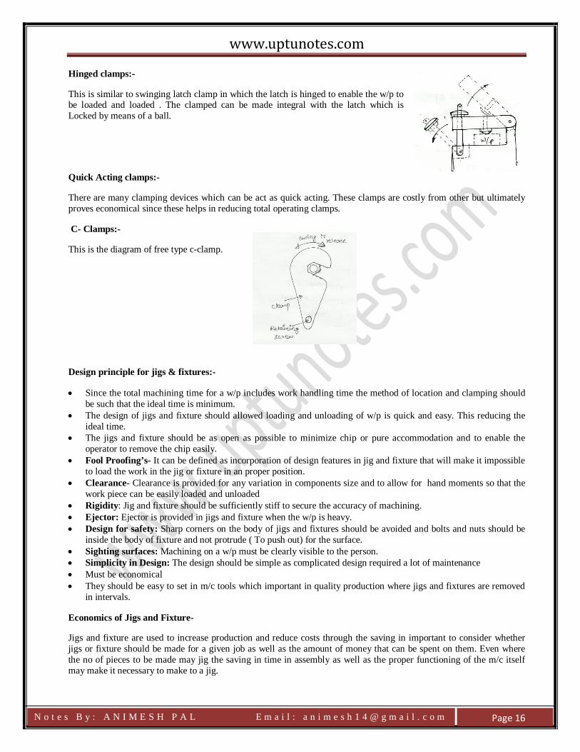
Hinged clamps:-
This is similar to swinging latch clamp in which the latch is hinged to enable the w/p to be loaded and loaded . The clamped can be made integral with the latch which is Locked by means of a ball.
Quick Acting clamps:-
There are many clamping devices which can be act as quick acting. These clamps are costly from other but ultimately proves economical since these helps in reducing total operating clamps.
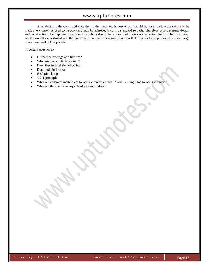
C- Clamps:-
This is the diagram of free type c-clamp.
Design principle for jigs & fixtures:-
• Since the total machining time for a w/p includes work handling time the method of location and clamping should be such that the ideal time is minimum.
• The design of jigs and fixture should allowed loading and unloading of w/p is quick and easy. This reducing the ideal time.
• The jigs and fixture should be as open as possible to minimize chip or pure accommodation and to enable the operator to remove the chip easily.
• Fool Proofing’s- It can be defined as incorporation of design features in jig and fixture that will make it impossible to load the work in the jig or fixture in an proper position.
• Clearance- Clearance is provided for any variation in components size and to allow for hand moments so that the work piece can be easily loaded and unloaded
• Rigidity: Jig and fixture should be sufficiently stiff to secure the accuracy of machining. • Ejector: Ejector is provided in jigs and fixture when the w/p is heavy. • Design for safety: Sharp corners on the body of jigs and fixtures should be avoided and bolts and nuts should be
inside the body of fixture and not protrude ( To push out) for the surface. • Sighting surfaces: Machining on a w/p must be clearly visible to the person. • Simplicity in Design: The design should be simple as complicated design required a lot of maintenance • Must be economical • They should be easy to set in m/c tools which important in quality production where jigs and fixtures are removed
in intervals.
Economics of Jigs and Fixture-
Jigs and fixture are used to increase production and reduce costs through the saving in important to consider whether jigs or fixture should be made for a given job as well as the amount of money that can be spent on them. Even where the no of pieces to be made may jig the saving in time in assembly as well as the proper functioning of the m/c itself may make it necessary to make to a jig.
N o t e s B y : A N I M E S H P A L E m a i l : a n i m e s h 1 4 @ g m a i l . c o m
Page 16
www.uptunotes.com
After deciding the construction of the jig the next step is cost which should not overshadow the saving to be made every time it is used some economy may be achieved by using standardize parts. Therefore before starting design and construction of equipment its economic analysis should be worked out. Two very important items to be considered are the initially investment and the production volume it is a simple reason that if items to be produced are few large investment will not be justified.
Important questions:-
• Difference b/w jigs and fixtures? • Why are jigs and fixture used ? • Describes in brief the following. • Diamond pin locator • Heel pin clamp • 3-2-1 principle • What are common methods of locating circular surfaces ? what V- angle foe locating circular ? • What are the economic aspects of jigs and fixture?
N o t e s B y : A N I M E S H P A L E m a i l : a n i m e s h 1 4 @ g m a i l . c o m
Page 17