pow-r-designer - eatonpub/@electrical/documents/content/...pow-r-designer occupies approximately...
TRANSCRIPT

User Manual
Cutler-Hammer, Inc. Pittsburgh, Pennsylvania
Version 1.07
Pow-R-DesignerPow-R-Designerf f o r W i n d o w s ® 9 5 / 9 8 / N T
Professional Software for One-Line Drawings and Electrical System Calculations
For electrical contractors, application engineers, consultants, and
other designers of electrical power distribution systems.
™

ii
User AgreementBy opening the sealed packets which contain the Pow-R-Designer™ Software diskettes,you are agreeing to the terms of this Agreement. If you do not agree to the terms ofthis Agreement, promptly return the unopened Software and related Softwaredocumentation.
Copyright and Duplication. The Software enclosed is protected by United StatesCopyright laws, with which you must comply. One (1) copy of the Software may bemade in machine readable form for use by you for backup and archival purposes only.
Use. You have the right to use the Software on a maximum of two computers. Youmay transfer the Software to other computers, but may not use the Softwaresimultaneously on multiple computers or in a shared access computer network, unlessadditional keys are purchased for site licensing purposes. For additional keys and sitelicensing information call 1-800-525-2000.
Nondisclosure. You shall hold the Software confidential, shall not disclose theSoftware to others, and shall use the Software only as set forth herein. You shallnot disassemble, decompile, or modify the Software. The data and informationincluded in the Software program is proprietary information of Cutler-Hammer Inc. and may be used by you solely for the purpose of providingdesign guidelines. It shall not be used for any other purpose or disclosed toany third party.
The calculations, procedures, and selections made by Pow-R-Designer™ generallyfollow those required and defined by the National Electric Code (NEC). However,there are certain inevitable limitations to the applicability of this Software.
Pow-R-Designer™ should be used only as an aid in performing calculations andevaluations. Pow-R-Designer™ is in no way intended to be a replacement for thecareful exercise of sound engineering judgment that must take place on everyproject. An engineer is responsible, using his or her knowledge of the NEC and ofthe project, to enter data correctly, to properly evaluate the displayed results, and todetermine if the results validly apply to the project under consideration.

iii
Limited Warranty and DisclaimerLimited Warranty. Cutler-Hammer Inc. warrants that the medium on which theSoftware is provided will be free from defects for a period of twelve (12) monthsfrom the date of receipt by you of the Software.
Disclaimer. The Software is provided “AS IS” and with the limited warranty statedabove. Cutler-Hammer Inc. disclaims all warranties of merchantability andfitness for particular purpose for software products covered by this Agreement.
Remedy. Your sole remedy and Cutler-Hammer Inc.’s sole liability in the event thatthe medium does not meet Cutler-Hammer Inc.’s Limited Warranty shall be, atCutler-Hammer Inc.’s option, to refund to you the purchase price of the Software orto replace the Software diskettes.
Damage Limitation. Cutler-Hammer is not responsible for results of use of theSoftware. You should verify your work. In no event shall Cutler-Hammer Inc.or its agents be liable to you or third parties for any direct, indirect,consequential, special, or incidental damages arising out of the use of theSoftware, even if advised of the possibility of such damages. In no case shallCutler-Hammer Inc.’s liability exceed the amount of the license fee.

Pow-R-Designer User Manual
iv
AutoCAD is a registered trademark of Autodesk, Inc.Internet Explorer is a registered trademark of Microsoft Corporation.Pentium is a registered trademark of Intel Corp.Windows 95/98/NT and Word are registered trademarks of Microsoft Corporation.
This document contains proprietary information that is protected by copyright. All rights are reserved. No part ofthis document may be photocopied, reproduced, or translated to another language without the prior writtenconsent of Cutler-Hammer. The information contained in this document is subject to change without notice.Cutler-Hammer cannot guarantee that changes in software will not affect the applicability of the information inthis documentation. All screens appearing in this documentation closely represent the actual screen.
Address all inquiries to: Cutler-Hammer, Inc.1000 Cherrington ParkwayMoon Township, Pennsylvania 15108Attn: Pow-R-Designer Marketing
Pow-R-Designer name and logo are registered trademarks of Cutler-Hammer.
© CUTLER-HAMMER, INC., 1999. ALL RIGHTS RESERVED. PRINTED IN THE UNITED STATES OF AMERICA.

v
ContentsINTRODUCTION ______________________________________________________________ VIII
ABOUT POW-R-DESIGNER™ ______________________________________________________ VIII
Pow-R-Designer Capabilities __________________________________________________ viii
CHAPTER 1: POW-R-DESIGNER BASICS___________________________________________8
PREPARING TO USE POW-R-DESIGNER________________________________________________8Computer Requirements _________________________________________________________8Installation Instructions _________________________________________________________8
Important installation notes ____________________________________________________________ 8OPENING POW-R-DESIGNER________________________________________________________8DEFAULT WINDOW _______________________________________________________________8POW-R-DESIGNER NOTABLE FEATURES ______________________________________________8CREATING A DRAWING—OVERVIEW _________________________________________________8
Note on general drawing strategy _______________________________________________________ 8
CHAPTER 2: MENU BAR COMMANDS_____________________________________________8
DESCRIPTION OF MENU BAR COMMANDS _____________________________________________8File _________________________________________________________________________8Edit _________________________________________________________________________8View_________________________________________________________________________8Mode (Quick) _________________________________________________________________8Schedules ____________________________________________________________________8
Exporting a Schedule to a Spreadsheet Application _________________________________________ 8Calculations __________________________________________________________________8
Motor Load Contributions of Transformers in Short Circuit Calculations ________________________ 8Options ______________________________________________________________________8Window ______________________________________________________________________8Help_________________________________________________________________________8
CHAPTER 3: TOOLBAR BUTTONS ________________________________________________8
DOCKABLE TOOLBAR _____________________________________________________________8DESCRIPTION OF TOOLBAR BUTTONS ________________________________________________8
New Drawing _________________________________________________________________8Open ________________________________________________________________________8Save_________________________________________________________________________8Print ________________________________________________________________________8Mail Drawing _________________________________________________________________8Cut__________________________________________________________________________8Copy ________________________________________________________________________8Paste ________________________________________________________________________8Find_________________________________________________________________________8

Pow-R-Designer User Manual
vi
Delete _______________________________________________________________________8Update Voltages _______________________________________________________________8Short Circuit Program __________________________________________________________8Consistency Check _____________________________________________________________8Schedules ____________________________________________________________________8Quick mode ___________________________________________________________________8Zoom Feature _______________________________________________________________ 33Product Information ____________________________________________________________8Help_________________________________________________________________________8
CHAPTER 4: PARTS BIN BUTTONS________________________________________________8
DESCRIPTION OF PARTS BIN PRODUCTS_______________________________________________8Utility Entrance _______________________________________________________________8
About Specification Data______________________________________________________________ 8Primary Switch—Fused _________________________________________________________8Primary Switch—Nonfused_______________________________________________________8Transformer __________________________________________________________________8
Note on the field Short Circuit ________________________________________________________ 39Low Voltage Switchgear ________________________________________________________39
The functions Copy, Paste, Auto Name, and Default Name for feeder devices ____________________ 8Switchboard—Freestanding ______________________________________________________8Distribution Panel—Wall Mounted ________________________________________________8Panelboard ___________________________________________________________________8
Note on downstream panelboard connections ______________________________________________ 8Motor Control Center___________________________________________________________8Loadcenter __________________________________________________________________46Cable________________________________________________________________________8
Note on Automatic Cable & Conduit Sizing _______________________________________________ 8Note on panelboards _________________________________________________________________ 8
Plug-In Busway________________________________________________________________8Feeder Busway ________________________________________________________________8
Note on feeder busway _______________________________________________________________ 8Disconnect Switch—Fused _______________________________________________________8Disconnect Switch—Nonfused ____________________________________________________8Enclosed Breaker ______________________________________________________________8Noncombination Starter _________________________________________________________8Combination Starter ____________________________________________________________8Individual Contactor____________________________________________________________8Automatic Transfer Switch _______________________________________________________8Power Factor Capacitor_________________________________________________________8Motor _______________________________________________________________________8Emergency Generator___________________________________________________________8Load ________________________________________________________________________8Deselect______________________________________________________________________8

vii
CHAPTER 5: CREATING A ONE-LINE DRAWING—A TUTORIAL ____________________8
GETTING STARTED _______________________________________________________________8SAVE YOUR WORK _______________________________________________________________8QUALIFICATION TO THIS TUTORIAL _________________________________________________8GENERAL DRAWING STRATEGY _____________________________________________________8CREATING THE DRAWING __________________________________________________________8
Place the utility entrance ________________________________________________________8Place the fused primary switch____________________________________________________8Place cable ___________________________________________________________________8Place a transformer ____________________________________________________________8Draw busway__________________________________________________________________8Place a motor control center _____________________________________________________8Place a switchboard ____________________________________________________________8Place a distribution panel _______________________________________________________8Place a motor _________________________________________________________________8
EDITING ________________________________________________________________________8Cut, Paste, Delete______________________________________________________________8Move, Resize Busway, Copy ______________________________________________________8Find, Disconnect Busway ________________________________________________________8
PERFORMING CALCULATIONS ______________________________________________________8Update Voltages _______________________________________________________________8Short Circuit Program __________________________________________________________8Consistency Check _____________________________________________________________8
CREATING SCHEDULES ____________________________________________________________8Prepare Schedules _____________________________________________________________8Set Schedule Title ______________________________________________________________8Print Schedules ________________________________________________________________8Change Schedule Column Sizes ___________________________________________________8Close Schedules _______________________________________________________________8
CREATING A SPECIFICATIONS GUIDE _________________________________________________8ADDING BITMAP IMAGES _________________________________________________________76PRINTING A DRAWING_____________________________________________________________8
INDEX ___________________________________________________________________________8

Pow-R-Designer User Manual
viii
IntroductionAbout Pow-R-Designer™
Pow-R-Designer is a Windows® 95/98/NT-based one-line drawingprogram, specifically created by the Cutler-Hammer corporation as asupport tool for designers of low voltage electrical power distributionsystems. Pow-R-Designer is designed to efficiently produce one-linedrawings, interface with CAD environments, and generate highlyaccurate calculations for the created diagrams.
As a state-of-the-art program for producing schematic drawings, Pow-R-Designer is a valuable tool for application engineers, consultants, andother designers of electrical power distribution systems. With it, youcan quickly select electrical products, cable, and busway from Pow-R-Designer’s Parts Bin and place them in your drawing. You can assign arange of electrical specifications to any product, then performcalculations on your design. You can also move, copy, delete, or searchfor these devices in your drawing.
Pow-R-Designer Capabilities In addition to creating one-linediagrams, users can:• Calculate available short-circuit fault current• Update voltages and calculate voltage drops• Run consistency checks• Generate product schedules• Generate specification guides• Export Pow-R-Designer files (.dxf) to programs such as AutoCAD®

ix
This page intentionally left blank.


1
Chapter 1: Pow-R-DesignerBasicsChapter 1 provides information on Pow-R-Designer computer requirements,installation, and features, with a brief look at Pow-R-Designer functions.
Preparing to Use Pow-R-Designer
Computer RequirementsRecommendedPentium® processor12 MB RAMWindows® 95, 98, NT 3.51 or higherPow-R-Designer occupies approximately nine megabytes of hard drive space
Installation Instructions*
1. Place Pow-R-Designer Disk 1 in your a: drive.2. At your Windows Desktop window, click on Start. The Start menu appears.3. Click on Settings, then on Control Panel.4. Double-click on the Add/Remove Programs icon. An Add/Remove Programs
Properties dialog box appears.5. Click on the Install button.6. Click on the Next button. Windows finds the Pow-R-Designer install file
automatically.7. Click on the Finish button. You are stepped through various dialog boxes.8. Continue clicking on Next until finished.
1. Place Disk 1 in your a: drive.2. Select Program Manager.3. Click on File, then Run.4. Type a: setup in the field and press Enter.5. Follow the prompts.
* Pow-R-Designer diskettes can be installed on two separate computers. A confirmation key is required for eachinstallation. For installation on three or more computers call 1-800-525-2000 for additional information and sitelicensing fees.
™
WINDOWS95, 98,NT 4.0
WINDOWSNT 3.51

Pow-R-Designer User Manual
2
Opening Pow-R-Designer
There are several ways to open Pow-R-Designer in Windows 95/98/NT once installed:• Go in via the desktop. Drag the file PDWIN.EXE from the Pow-R-Designer folder
to your desktop, then double-click on it to open the application.• Click on the shortcut on the Start menu. Place PDWIN.EXE on your Start menu,
then click on it to open Pow-R-Designer.• Type “pdwin” in the Run dialog box. Click on Start, then on Run. Type the Pow-
R-Designer drive and path and “pdwin.exe,” then press Enter.• Use the Programs option. Click on Start, point to Programs and Pow-R-Designer,
then click on the icon.
Important installation notesPermanent Installation Pow-R-Designer uses a security system that requires you to register and acquire aconfirmation key as soon as possible after installing this application. Call the Cutler-Hammer Fulfillment Center at1-800-525-2000 to obtain this number. Without it, Pow-R-Designer performs, from installation, for a 10-dayperiod only. After this period, no work in Pow-R-Designer is possible. However, you will see a pop-up windowrequesting the confirmation key, which can be installed immediately by calling the Cutler-Hammer FulfillmentCenter. Be prepared to provide your name, address, company, and user ID number. The user ID appearsduring installation.
Reinstallation Pow-R-Designer diskettes can be installed on two computers after the initial purchase. Thesoftware can, however, be moved from one computer to another using the same set of disks, you will need torequest another confirmation key at the time of installation. If you plan on using one copy of the software on morethan two machines you should call 800-525-2000 and inquire about the site licensing requirements. Note:Delete the Pow-R-Designer directory from your computer.

Chapter 3: Toolbar Buttons
3
Default Window After you start Pow-R-Designer, the default window below appears. This graphicindicates Pow-R-Designer’s notable features.
Parts bin
Toolbar
Menu bar
Title blockfeatures
Drawingspace
Drawingsize
Pow-R-Designer Notable Features The following defines the notable features of Pow-R-Designer: Drawing size: A function that provides increasingly larger areas in
which to create your one-line drawing. Five sizes, A through E, rangefrom smallest to largest. Note: The drawing’s apparent screen sizeremains the same after you change the drawing size. However, thesize of the printout changes.
Drawing space: The portion of the window where you create yourdrawing.
Menu bar: The bar beneath the title bar containing the drawingcontrol menu and menu items used to access program functions.
Parts bin: This dockable bar contains the devices or products onwhich you click to place items in the drawing. You can form the partsbin into various configurations and place it where you want in thewindow.

Pow-R-Designer User Manual
4
Title Block features: Title block features include borders, footerblocks, a revision block, and a title block. You see these features inthe drawing space and on your printout.
Toolbar: A dockable bar displayed just below the menu barcontaining command buttons that offer quick access to several of thefunctions found in the menu bar.
Creating a Drawing—Overview This section provides a template for creating a one-line drawing in Pow-R-Designer. Ifyou are a first-time user of this program, you may find the typical approach outlinedbelow useful. The order of the following steps and the details of their contents serve asguidelines only; you will eventually develop your own approach. Many projects requiretheir own order of events as well.
1. Create name for file 9. Join products to busway 2. Select printout size 10. Move, copy, or delete 3. Dock toolbars 11. Find (search for) a product 4. Place utility entrance 12. Change font 5. Place other products 13. Perform calculations 6. Join products with cable/busway 14. Prepare schedule 7. Create busway 15. Export spec guide 8. Perform product selection 16. Export drawing to CAD
These steps are briefly explained below:
1. Create a file name: Click onFile on the menu bar, then on SaveAs. At the Save As dialog box, clickon the drive and folder where youwant the drawing file to reside, thentype a name in the field File Name.Click on the Save button. Thisprocedure not only names your work, but also establishes a file and pathfor it. Save frequently as you work to mitigate data loss due toelectrical outages, software conflicts, or computer failures. Note: Youcan also display the Save As dialog box by clicking on the Save button if

Chapter 3: Toolbar Buttons
5
your current drawing has not yet been saved. Hot keys = Alt F, A. SeeSave and Save As sections in Chapter 2. 2. Select a size for your printout: This printout size control is to theleft of and just above the drawing space. Size A, the default size,provides the smallest of five printout sizes available. Size E is thelargest—here you can place the greatest number of products. Click onthe drawing-size down arrow and scroll to find the size you want.These sizes correspond to traditional draftsman’s standards: A = 8½ 511", B = 11 5 17", C = 17 5 22", D = 22 5 34, and E = 34 5 44".This size can be changed any time during your work. Note: Changesare not apparent onscreen as you switch from one size to another.However, you can see a change in the size of the scroll-bar sliders asyou use this function. 3. Move and dock the toolbar and/or the parts bin: If you prefer toplace a button group (toolbar or parts bin) in another area of the defaultwindow, press and drag on the border of this group. You not only canrelocate the assembly to another part of your screen, but you can alsoreshape it in various ways as you continue to drag on its border. Thesearrangements are preserved when you save your drawing and are foundin the same position when you access that drawing again in the future. 4. Configure and place the utility entrance:∗∗ Depending on the job,the utility entrance is generally where you begin a drawing. Click on theUtility Entrance button, move the pointer to the drawing space, thenclick again. Complete the fields in the displayed Service Entrance dialogbox, then click on OK. The service symbol appears in your drawing.See also the Utility Entrance section in Chapter 4. 5. Configure and place other products:\\ The parts bin is designedso that the user can place products in the drawing from the left side ofthe (default) parts bin first. Products on the right side of the parts binare likely placed later, typically speaking. Place a product by clicking ona parts bin button, clicking on the desired location in the drawing, then
∗ To alter specifications for any product, double-click on that product in your drawing. Doing sodisplays its dialog box, where you can make the revisions.
The utility entrance mustbe present in a drawingfor Pow-R-Designer toperform a short circuitcalculation.
Size A prints out on one8½ 5 11" sheet, Size Btwo, Size C four, Size Deight, and Size E sixteen,as shown above.
A B C D E

Pow-R-Designer User Manual
6
completing the displayed dialog box. Note: In the drawing, a productcan be connected to another product by placing it under and touchingthe other product. A connection is indicated by a small solid squarejoining both products. It is not necessary to immediately connectproducts when placing them in your drawing. +You can placeproducts without completing all dialog box fields by first selectingQuick under Mode on the menu bar. See also Chapter 4: Parts BinButtons. 6. Join products with cable: Click on the Cable button in the partsbin. Click on the bottom of the upstream product for the firstconnection, then click on the top of the downstream product for thesecond. Complete the fields in the Cable and Conduit Data dialog box.Note: Connecting products with feeder busway is similar to connectingproducts with cable. See section on Cable in Chapter 4. 7. Create busway: Click on the Plug-In Busway (you manage FeederBusway more like cable—see step 6 above) button in the parts bin.Click in the drawing space where you want to run the busway. Releasethe mouse button; drag to the length you want, then click again at thebusway endpoint. A Busway Properties dialog box appears. Completethe fields, then click on OK. See sections on Plug-In Busway andFeeder Busway in Chapter 4. 8. Select product(s): You select one or more products to move oredit them, or to revise product specifications. Ways to select:• Product: Click on a product (double-click to display dialog box)• Multiple products: Hold down Shift or Ctrl while clicking on
products• Drag-select: Click and drag on a portion of the drawing space. All
products and portions thereof within the dotted outline are selected.• Select all products: Click on Edit on the menu bar, then on Select
All. All products in the current drawing are selected.
To deselect products,click anywhere in theclient area.

Chapter 3: Toolbar Buttons
7
9. Join products to plug-in busway: Move an existing productbeneath and in contact with plug-in busway. (You can also connectbusway to products with cable.) Move the product by clicking on anddragging it. (Feeder busway is drawn like cable; see step 6.) 10. Move, cut, copy, paste, or delete products: Several editingfunctions are available in Pow-R-Designer. You must first select theproduct (see step 8 above). Then perform the desired edit using menubar commands or toolbar buttons. See the Edit section in Chapter 2.,and Cut, Copy, and Paste sections in Chapter 3. Edit commands are available:• On the toolbar• By right-clicking in the drawing space, or• By clicking on Edit on the menu bar (see Chapter 2, Menu Bar
Commands).
11. Find (search for) a product: As a drawing job becomes largerand more complex, finding a given product in your drawing may takelonger by eye. Click on the Find button to display the Object Name list.Click on the designation for the object you want to find, then click onOK. The sought product becomes outlined. See Find sections inChapter 2 and Chapter 3.
12. Change product-label fonts: Drawing jobs may become complexto the point where labels overlap with products and each other. Or youmay prefer to enlarge them for visibility. To change a font, click onEdit, then on Font. Select the size and/or style you want, then click onOK. Click on a product to effect the change. All labels display therevision. Hot key = Alt E, F. See Font section in Chapter 2.
13. Perform calculations: You can perform certain calculations onthe products you’ve laid out. These calculations are Update Voltages,Short Circuit Program, and Consistency Check. Click on Calculationson the menu bar. Hot key = Alt C, then select.
14. Prepare product schedule: To create a schedule of products andspecifications, click on Schedules on the menu bar (or on the Schedules
To move a product, clickon it and drag it to thedesired location.
While the schedule isdisplayed, you can:• Print it: Click on thePrint button, or selectFile on the menu bar,then Print.• Copy it: Drag acrossthe tops of all columns toselect the spreadsheet.Press Ctrl+C to copy.Open a spreadsheetapplication, then pressCtrl+V to paste. Editand/or Save this file.

Pow-R-Designer User Manual
8
button on the toolbar), then on Prepare Schedule. Click on the fields ofthe products you want to appear in the schedule. Click on OK todisplay the schedule. To exit schedules, click on the close button on themenu bar. Hot key = Alt D, S. +While the schedule is displayed, clickon Schedules on the menu bar, then on Set Schedule Title to provide aname for the current schedule. This name appears on the printout only.Hot key = Alt D, T. See section on Schedules in Chapter 2. Note:You can save a Pow-R-Designer schedule as a .txt file in Notepad forediting purposes. However, a spreadsheet program manages yourinformation much more conveniently for performing those edits.
15. Create spec guide for drawing: In the process of placing aproduct, you work in a dialog box for that product. At this dialog box,click on the button Spec Data, then complete the information in thecolumn Value. This prepares Pow-R-Designer to create a specificationguide for the current drawing. When you have completed this processfor all desired products, click on File on the menu bar, on Export, thenon Spec Guide. Click on the folder where you want the specificationguide to reside, then type a name for it. Click on OK. Hot key = Alt F,E, S. See Export section in Chapter 2. Note: Specifications can begenerated for each individual piece of equipment in the one-line bycompleting spec data accordingly, or a single specification section canbe generated by completing one spec guide for each category ofequipment. 16. Export drawing to a CAD application: Click on File on the menubar, then on Export. Provide a name and a path for the current drawingin the displayed dialog box. Access this .dxf file later from your CADprogram. Hot key = Alt F, E, A. See Export section in Chapter 2.
General drawing strategyTesting and actual field use of Pow-R-Designer have shown that a “fan-out” product-placement processworks best: Attach larger products to the outside of their parent components, and group smaller productsnear the middle of those parent components. This makes products seem to fan out as you view the drawingoverall. This strategy is suggested to mitigate the grouping of bigger products. If larger products grouptogether, such groupings tend to choke pathways for smaller products and their associated cable which canresult in awkward placements and overlaps.Note: The larger the drawing, the more significance this strategy acquires.
To view and print yourspecification guide .rtf file,access it from a wordprocessing program,where you can also edit it.
Summary: Pow-R-Designer creates a .dxfextension for exporting toan editing program, a .txtextension for schedules,and an .rtf extension forspec guides.

Chapter 3: Toolbar Buttons
9
Chapter 2: Menu Bar Commands
Chapter 2 describes Pow-R-Designer menu bar functions. The menu bar resides nearthe top of the Pow-R-Designer window. Use your mouse to access these areas:• File• Edit• View• Mode• Schedules
• Calculations• Options• Window• Help
Description of Menu Bar Commands
File Click on File to access these commands (shown at left): NewDrawing, Open, Close, Save, Save As, Print, Print Preview, Print Setup,Export, Font, Existing (1, 2, 3...) files, and Exit. Click on the commandyou want. These commands are explained below:
New Drawing: This command displays a blank Pow-R-Designerdrawing space for creating a new one-line drawing. If anotherdrawing was open when you implemented this command, it remainsopen but hidden. To display a hidden drawing, click on Window onthe menu bar, then click on the file name you want at the Windowmenu. FYou can also click on the New Drawing button (seetoolbar) to open a new drawing. Open: This command opensa stored drawing. When youclick on Open, a File Opendialog box appears. Dialogbox commands are: Look in:Select the drive and directorywhere your drawing is stored.Double-click on a directory tosee subdirectories. Scroll to see more directories, if available.

Pow-R-Designer User Manual
10
File Name: Type or scroll to the name of the drawing you want toopen. Files of Type: Scroll through these file name extensions toselect the kinds of files you want to display in the file name field.The default extension for Pow-R-Designer drawings is .pd.FAlternatively, you can access the Open dialog box by pressingCtrl+O or clicking on the Open button (see toolbar). FYou canopen multiple drawings. To display an active but hidden drawing,click on Window on the menu bar, then on the name of the file youwant. The list of files on the Window menu reflects all currentlyopen drawings and schedules. Close: This command closes the active drawing. If you haveseveral windows of the active drawing open, this command closes allof them. When you click on Close, Pow-R-Designer prompts youto save your work (unless you have not made any changes sinceyour last save). FBefore saving your drawing, run a short circuitprogram. FAlternatively, you can close your drawing by double-clicking on the control menu icon. Or close by clicking on thecontrol menu on the menu bar, then clicking on Close. Or you canclick on the Close button on the toolbar. FIf you close a drawingwithout saving, you lose all changes since your last save. Save: This command saves the displayed drawing to its currentname and directory. When you save a drawing for the first time,Pow-R-Designer displays the Save As dialog box so you can nameyour drawing. If you want to change the name and directory of thecurrent drawing, use the command Save As. If you close a drawingwithout saving it, you lose all changes since your last update.FYou can also save your drawing by pressing Ctrl+S or by clickingon the Save button (see toolbar). FBefore saving your drawing,run a short circuit program.

Chapter 3: Toolbar Buttons
11
Save As: This commandsaves the current drawingto another directory orunder a new, thuscreating a copy of thedrawing. After you useSave As, the drawing yousee on your screen is thenew version. When you click on Save As, a Save As dialog boxappears. Dialog box commands are: Save in: Select the drive anddirectory where you want your drawing stored. Double-click on adirectory to see subdirectories. Scroll to see more directories. Filename: Type or change the name of the drawing you want to save.Save as type: Pow-R-Designer appends the extension .pd bydefault. Or you can type the extension you choose. When you arefinished, click on OK. FUse the command Save to save a drawingunder its existing name and directory. FBefore saving yourdrawing, run a short circuit program. Export: Use this File menu command to copy drawing data to aCAD file or to a Pow-R-Designer specification guide. When youplace your cursor on Export, the commands AutoCAD and SpecGuide appear. AutoCAD: Click on AutoCAD to access an ExportDrawing as DXF File dialog box (note that the “header.dxf” file isessential to the export process. Do not delete or rename this file).Click on the drive and folder where you want to save this file, thentype a file name. The default location for these files is the mainPow-R-Designer directory. Click on Save to convert the currentdrawing to a DXF-compatible file and to store it in your chosenlocation. Spec Guide: Click on Spec Guide to compile into an RTFfile specifications data that you previously entered at product dialogboxes. You created these specifications when you clicked on theSpec Data button at a dialog box, then typed information in thedisplayed table. When you click on Spec Guide, a Save Spec Guideas an *.rtf File dialog box appears. Click on the drive and folderwhere you want to save this file, then type a file name. The defaultlocation for these files is the main Pow-R-Designer directory. Click
Print spec guide: Toview or print your speci-fication guide, save it asan *.rtf file, then access itthrough your wordprocessing program

Pow-R-Designer User Manual
12
on Save to convert the current specifications guide to an RTF-compatible file and store it in your chosen location. To view andprint this file in the future, access it through your word processingprogram. Mail Drawing: If you have e-mail, click here to send drawingsto a recipient’s computer. Whenyou click on Mail Drawing (or onthe Mail Drawing button on thetoolbar), a New Message dialogbox appears. This dialog boxdisplays your current drawing. You can e-mail this drawing, attachanother file, or type your own message at this dialog box. Faxcapabilities are available here if you are set up for it. Print: Use this command toprint the current one-linedrawing. When you clickon the Print button, a Printdialog box appears. Withthis box, you can print allpages of your drawing,select a print range ofpages, choose the printoutquality, opt for multiplecopies of the drawing, and perform collation. This dialog box alsodisplays the following information: Name: The active printer andprinter connection. Click on the down arrow to browse youravailable printers. Click on the printer you want if you don’t wantthe default printer. Status: The category of the printer setup andthat printer’s availability. Type: The hardware name of the printer.Where: The path, directory, or network where the printer isconnected. Comment: Additional information about the printingenvironment. Print to file: Click on this field if you want to save aprinted version of your drawing in a file for later printing or transferto another application. All: Click here to print all pages of the
Configure your computerfor Exchange or Outlookto mail a drawing.

Chapter 3: Toolbar Buttons
13
current drawing. Pages from…to….: Type the range of pages youwant to print here. Number of copies: Select a number. Collate:Click on this field if you want your multiple copies to have collation.Properties: If you click on the Properties button, a Propertiesdialog box appears. Click on the tab you need to access the printfunction you want to address. Print Preview: This command displays the current drawing as itwould appear when printed. The main window is replaced by aPrint Preview window in which one or two pages are displayed inthe printed format. At Print Preview, you can (see the Print Previewtoolbar):• View either one or two pages at a time• Move among multiple pages• Zoom in and out• Initiate a print job.
Print Setup: Thesettings in thePrint Setup dialogbox are: Name:The active printerand printerconnection. Clickon the downarrow to browseyour availableprinters. Click onthe printer youwant if you don’t want the default printer. Status: The category ofthe printer setup and that printer’s availability. Type: The hardwarename of the printer. Where: The path, directory, or network wherethe printer is connected. Comment: Additional information aboutthe printing environment. Paper: Several paper sizes and sourcesmay be available to a given printer. Select these options here.Orientation: Click on Portrait or Landscape to orient your printeddrawing. Properties: Read about Properties above.

Pow-R-Designer User Manual
14
Existing files: Also called 1, 2, 3 files because these numbersrepresent a list of numbered files, these commands open the mostrecently saved Pow-R-Designer drawings. Click on the file youwant to open. FYou can open multiple drawings. To display anactive but hidden drawing, click on Window on the menu bar, thenon the name of the file you want. The list of files on the Windowmenu reflects all currently open drawings and schedules.
Exit: This command closes Pow-R-Designer. You are prompted tosave drawings you have changed since your last save. FAlternativeways to end your Pow-R-Designer session are by pressing Alt+F4,and by double-clicking on the control menu on the title bar.
Edit Click on Edit to access these commands: Cut, Copy, Paste,Delete, Find, Select All, Disconnect Cable/Fdr Busway, Resize Busway,Disconnect Busway, and Font. (The Edit menu is also available byright-clicking in the drawing space.)
Cut This command removes selected products from your drawingand stores them on the clipboard. First select the product(s) youwant to cut. Then click on Edit on the menu bar, then on Cut. Thisremoves the product. The product is now available on the clipboardfor pasting elsewhere in your drawing. FOther ways to cut aproduct are: Click on the toolbar’s Cut button, press Ctrl+X, orright-click in the drawing space. Note: To select multiple products,
Cascade/Tile at the Win-dow menu allows you toview multiple open win-dows.
To deselect products,click anywhere in theclient area.
Moving products in a drawingThe move command is not available on the Edit menu, but is a primary editing procedure.To move a product in your drawing, click on and drag the product to the desired location.You can select more than one product: 1) Hold down Ctrl or Shift, then click on thetarget products. 2) Drag on an area in your drawing. 3) Click on Edit, then on Select Allto select all products. FThe move function is not useful on cable. If you must “move” acable, a better procedure would be to delete the target cable, then draw another one.FWhen you move one product away from another, the connection between them isbroken. But if you move a product which has a cable connection, the cable moves with itand remains connected to it.

Chapter 3: Toolbar Buttons
15
hold down the Ctrl or Shift key while clicking on the targetproducts.
Copy This command makes copies of selected products in yourdrawing. First select the product(s) you want to copy. Then clickon Edit on the menu bar, then on Copy. Then click on Edit, then onPaste. The copied product appears at the top of your drawing.Move this copy to the desired location. FOther ways to copy aproduct are: Click on the Copy button, press Ctrl+C, or right-clickin the drawing space. Note: To select multiple products to copy,hold down the Ctrl or Shift key while clicking on the targetproducts.
Paste This command places a copy of the clipboard contents inyour drawing. Click on Edit on the menu bar, then on Paste. Theproduct appears at the top of your drawing.FOther ways to paste aproduct are to click on the toolbar’s Paste button or press Ctrl+V.
You may want to paste products from the clipboard by clickingthe right mouse button in the drawing space. This method allowsyou to paste a product where you want it after a Cut or Copyfunction. To place a product approximately where you want in thedrawing, right-click on the desired target location. An edit menuappears. Click on Paste on this menu. The product appears wherethe edit menu was.
Delete This command removes selected products from yourdrawing. First select the product(s) you want to delete. Then clickon Edit on the menu bar, then on Delete. The product is removed.FAnother way to delete a product is to press the Delete key on
A new designation isgenerated for a copiedproduct following a copyfunction. You can dou-ble-click on the copiedproduct if you want tochange the designation orany other parameter inthe displayed dialog box.
If you don’t want a pastedproduct to default to thetop of your screen, seethe Paste tip here.
Nested productOn occasion, a product is placed unintentionally inside a larger product, perhaps as aresult of a Paste or Find function. When you try to move the smaller product, the largerproduct moves too. To retrieve a product from this “nested” location, follow these steps:Click on the Find button on the toolbar. Click on the designation of the product you wishto extract in the displayed Find dialog box. Click on OK. Click on Cut, then either 1) clickon the Paste button. The target product is salvaged and reappears at the top of yourscreen, accessible to a Move function; or 2), right-click in the drawing space where youwant the product to reside, then click on Paste on the displayed edit menu. The productreappears where you clicked.

Pow-R-Designer User Manual
16
your keyboard, or to click on the toolbar’s Delete button. Note: Toselect multiple products, hold down the Ctrl or Shift key whileclicking on the target products.
Find This command searches for, and outlineswhen found, a specified product in the currentdrawing. As drawings become more detailed,this feature becomes more helpful. Find aproduct by clicking on Edit on the menu bar,then clicking on Find. A Find dialog box appearsthat contains a Designation list. On this list, clickon the product you want. The product thenappears highlighted in your drawing. FYou canalso access the Find dialog box by clicking on theFind button on the toolbar.
Select All This command selects (outlines) all products in yourdrawing at once.
Disconnect Cable/Fdr Busway This command disconnects a cableor feeder busway from a current product so it can be moved toanother product. First select the cable or feeder busway to bedisconnected by clicking your mouse on it. Then click Edit on themenu bar, then on Disconnect Cable/Fdr Busway. From the dialogbox, select either the downstream product, upstream product, orboth to disconnect from the cable/feeder busway. Click your mouseon the end of the cable or feeder busway that you want to move.Drag the cable to its new connection location.
Resize Busway This command adjusts the length of selectedbusway in your drawing. First select the busway you want to resize.Then click on Edit on the menu bar, then on Resize Busway. Drageither end of the busway to the length you want. FYou can alsoaccess Resize Busway by right-clicking in the drawing space.
Disconnect Busway This command deletes the busway-to-productconnection in your drawing. First select the busway you want to
To reconnect busway:Click on the busway.Click on Move. Movethe busway slightly.Click in the client areaaway from a product todeselect the busway.The connection pointsreappear on thebusway.
Chapter 3: Toolbar Buttons
17
disconnect. Then click on Edit on the menu bar, then on DisconnectBusway. FYou can also access Disconnect Busway by right-clicking in the drawing space.
Font This command accesses a Font dialog box where you selectthe font, font style, font size, and font effects for application to thetext in your drawing. This application is global; all text in yourdrawing is affected. Scroll through and click on the options youwant. FAt the size option, you can either click on a displayedavailable size, or you can type a size in the top field.
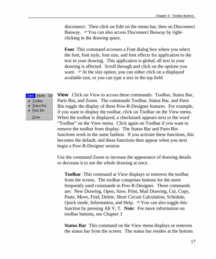
View Click on View to access these commands: Toolbar, Status Bar,Parts Bin, and Zoom. The commands Toolbar, Status Bar, and PartsBin toggle the display of these Pow-R-Designer features. For example,if you want to display the toolbar, click on Toolbar on the View menu.When the toolbar is displayed, a checkmark appears next to the word“Toolbar” on the View menu. Click again on Toolbar if you want toremove the toolbar from display. The Status Bar and Parts Binfunctions work in the same fashion. If you activate these functions, thisbecomes the default, and these functions then appear when you nextbegin a Pow-R-Designer session.
Use the command Zoom to increase the appearance of drawing detailsor decrease it to see the whole drawing at once.
Toolbar This command at View displays or removes the toolbarfrom the screen. The toolbar comprises buttons for the morefrequently used commands in Pow-R-Designer. These commandsare: New Drawing, Open, Save, Print, Mail Drawing, Cut, Copy,Paste, Move, Find, Delete, Short Circuit Calculation, Schedule,Quick mode, Information, and Help. FYou can also toggle thisfunction by pressing Alt V, T. Note: For more information ontoolbar buttons, see Chapter 3
Status Bar This command on the View menu displays or removesthe status bar from the screen. The status bar resides at the bottom

Pow-R-Designer User Manual
18
of the Pow-R-Designer window. When you click (without releasingthe mouse button) on commands on the various menu bar items orbuttons on the toolbar, the status bar displays a description of thesecommands. If you do not wish to execute a command, do notrelease the mouse button until you have moved the cursor awayfrom the area. In the right-hand area of the status bar, three fieldsdisplay whether the Caps Lock, Num Lock, or Scroll Lock keys arelatched down.
Parts Bin This command on the View menu displays or removesthe parts bin from the screen. The parts bin is used for selecting thespecific products you want to place in your drawing. For moreinformation on parts bin buttons, see Chapter 4.
Zoom To change the size of the drawing you see on your screen,click on View on the menu bar, then on Zoom. A Zoom dialog boxappears. Move the slider to the percent change in size that youwant, then click on OK. The drawing reappears at the new size.Note: When printing, the zoom factor is taken into consideration.To print a drawing at actual size (i.e., A Size = 8 ½ × 11), set thezoom factor to 100% before printing.
Mode Click on Mode to access Quick, a method for quickly placingproducts in your drawing. Quick mode affects the dialog box thatappears after you select an item from the parts bin or double click on aplaced product. A checkmark appears at Quick to indicate this mode isactive.
Quick Use this command if you want to lay out a drawing quickly.Quick mode is also useful for drawing a conceptual diagram inwhich there is no need to fulfill any of the technical aspects. UnderQuick mode, you type only a designation in the Quick ModeSpecification dialog box. The function Quick bypasses therequirement of completing all fields in product dialog boxes.Therefore, when Quick is active, you are not able to specifyparameters in product dialog boxes. Note: The switchboard,
Set Zoom to 100%when printing toachieve actualdrawing size.
To nullify Quickmode for a givenproduct: In yourdrawing, double-clickon the product, thencomplete the re-quired fields in thedisplayed dialog box.

Chapter 3: Toolbar Buttons
19
distribution panel, panelboard, and motor control center do notfunction when Pow-R-Designer is in Quick mode.
Schedules Click on Schedules to access the commands PrepareSchedule and Set Schedule Title. You create product schedules andname them with these commands.
Prepare Schedule This command produces a read-onlyspreadsheet-type schedule of products and specifications forproducts that use schedules. To prepare schedules for the currentdrawing, begin by clicking on Schedules on the menu bar, then onPrepare Schedule. A dialog box appears. Click on the fields forthose products you want to appear in the schedule. Click on thebutton Check All if you want to place all products in the schedule.Click on Uncheck All if you want to remove all checkmarks fromthe product fields. Click on OK to display the schedule containingthe products and their specifications. To give this schedule a title,see Set Schedule Title below. FTo return to your drawing whileleaving the schedule open, click on Window on the menu bar, thenon the name of your drawing. Or, to close the schedule and returnto the active window, click on the Close button on the menu bar.Note: While in a schedule, be sure to use scroll bars to view allinformation.
Set Schedule Title This command puts the title you want on theprintout of the current schedule. When you are working within aschedule (see Prepare Schedule above), click on Schedules on the
When you click on theSchedules button, this dialogbox appears. The productsyou click on here appear inyour schedule.
To see the cable-associated valuesNominal Voltage,Typical LoadCurrent, and Volt-age Drop, look inthe Cable section ofthe schedule.
Run a voltage up-date and a shortcircuit programbefore creating aschedule.
Pow-R-Designer User Manual
20
menu bar, then on Set Schedule Title. A dialog box appears. Typea name for the current schedule in the displayed field, then click onOK to confirm it. Note: This title appears only on the printout ofthe schedule. FTo return to your drawing while leaving theschedule open, click on Window on the menu bar, then on the nameof your drawing. Or, to close the schedule and return to the activewindow, click on the Close button on the menu bar.
Saving a schedule: See Exporting a Schedule to a Spreadsheetin box above.
Printing a schedule: While your schedule is displayed in Pow-R-Designer, click on File on the menu bar, then on Print. APrint dialog box appears which you can use to choose printoptions. Click on OK to send this job to the printer. If you havenot named your schedule (see Set Schedule Title above), adefault printout name appears (“Pow-R-Designer Schedule”).
Removing a column: By default, all columns appear in aschedule. To remove a superfluous column:
1. Click on Options on the menu bar, then on the commandSchedules. The Schedule Options dialog box appears.
2. Click on the product from which you want to remove schedulecolumns.
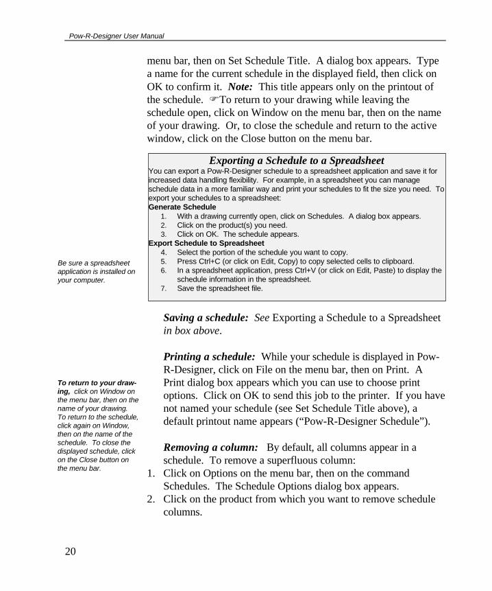
Exporting a Schedule to a SpreadsheetYou can export a Pow-R-Designer schedule to a spreadsheet application and save it forincreased data handling flexibility. For example, in a spreadsheet you can manageschedule data in a more familiar way and print your schedules to fit the size you need. Toexport your schedules to a spreadsheet:Generate Schedule
1. With a drawing currently open, click on Schedules. A dialog box appears.2. Click on the product(s) you need.3. Click on OK. The schedule appears.
Export Schedule to Spreadsheet4. Select the portion of the schedule you want to copy.5. Press Ctrl+C (or click on Edit, Copy) to copy selected cells to clipboard.6. In a spreadsheet application, press Ctrl+V (or click on Edit, Paste) to display the
schedule information in the spreadsheet.7. Save the spreadsheet file.
Be sure a spreadsheetapplication is installed onyour computer.
To return to your draw-ing, click on Window onthe menu bar, then on thename of your drawing.To return to the schedule,click again on Window,then on the name of theschedule. To close thedisplayed schedule, clickon the Close button onthe menu bar.

Chapter 3: Toolbar Buttons
21
3. Click on the target check box to remove the check mark and theassociated column from the schedule. When you regenerate theschedule, this column will not appear in it.
Changing column sizes in schedule: Some cell text andcolumn header names are long enough to be partially out ofview. To see this information, you can widen the columns. Todo so, position the cursor on a partition between columns at thetop of the schedule. When the cursor becomes a double linewith arrows (see picture at left), click and drag the partition untilthe column is the size you want.
Calculations Click on Calculations to access these commands:Update Voltages, Short Circuit Program, and Consistency Check.
Update Voltages Click on this command to update displayeddrawing voltages when you revise product parameters. Voltagedrops (red numbers in drawing) are also calculated here (see sidenote at Schedules, above). Note: Busway voltage drop isconsidered negligible and thus not calculated.
Example of Pow-R-Designer product schedule. To view all available information, you can drag onthe scroll bars, drag on the edge of the window, or widen the columns.

Pow-R-Designer User Manual
22
Short Circuit Program Click on this command to calculateavailable short circuit fault current (red numbers in drawing). Bydefault, this value appears in red next to each product’s node.
Quick breaker substitution: Pow-R-Designer displays, ifneeded, a Change Itemsdialog box used forproviding alternativevalid breakers during theshort circuit analysis. Ifyou change specificationsat certain products(enclosed breaker, MCC,distribution panel, switchboard, and panelboard), breakersexisting elsewhere in the drawing may no longer be appropriate.The Change Items dialog box is designed to offer the leastexpensive (and safe) available breaker. This dialog box displays• where the existing breakers reside (“Designation”)• the name of the existing breakers (“Current”)• the available alternative breakers (“Change To”). Under Change To, each drop-down menu lists substitutebreakers according to cost, the top breaker being the cheapest.Note: To turn off the Change Items feature, click on Options onthe menu bar, then on Calculations. Click on the Breaker tab,then on the “Warn before changing breakers” field, removing thecheck from the box. When this feature is turned off, the ChangeItems dialog box does not appear when you perform a shortcircuit evaluation. Read the section on Calculations underOptions below.
A short circuit calcula-tion can only be per-formed if a utility en-trance is present in yourdrawing.
A short circuit analysisis necessary if youwant Pow-R-Designerto substitute the newbreaker.

Chapter 3: Toolbar Buttons
23
Consistency Check† Click on this command to check that devicesupstream and downstream from transformers are the correct sizes.
Options Click on Options to display the commands Calculations,Display, Manufacturer, Schedules, and Snap to Grid.
Calculations‡ When you click on this option, a CalculationsOptions dialog box displays• a tab for the default system power factor that is used in voltage
drop calculations, and• a tab for automatic breaker substitution options Here’s how to use these tabs:
Voltage Drop: You can change this power factor by typing thevalue you want in the field System Power Factor (0.8 is thedefault). The voltage drop adjusts accordingly. Note: Be sureto run new calculations (voltage update, short circuit program,and consistency check) if you change this default value.
† In low voltage systems, you receive an error message if the motor voltage drop is >8.33% (>5% forall other devices). In medium voltage systems, you receive an error message if the motor voltage dropis >10% and >2.5% for all other devices. This calculation also checks whether each individual cablehas <3% voltage drop. ‡ Do not confuse this option with the menu item Calculations which contains Voltage Update, ShortCircuit Program, and Consistency Check.
Changing the systempower factor affects thedisplayed voltage dropcalculations and imped-ances.
Motor Load Contribution of Transformers in Short Circuit Calculations Service Transformer: The service transformer is the transformer occurring before the first switchboard, dis-tribution panel, or bus. If the motor load percent at this transformer is 100 or above, all other downstream motorloads in the system are not considered by the short circuit calculation. The only motor load taken into considerationis the assumed motor load of the service transformer. If the motor load percent of the service transformer is below100
*, all motor loads and motor contributions of transformers in the entire system are considered in the short circuit
calculation. Any other transformer: Motor contributions from this point downstream, in addition to the motor load percent atthis transformer, are all taken into consideration by the short circuit calculation. * The default motor load percent for the service transformer is 100. However, you may type a lower percent in this field. If you do, thenthe short circuit calculation for the service transformer takes into account the motor load contributions of all the other motors and trans-formers in the system. Otherwise it does not.

Pow-R-Designer User Manual
24
Auto-Change: At this tab, you control whether Pow-R-Designer updates yourbreakers due to a changein short circuit rating. Italso provides a way to seeyour intended selectionsbefore they actuallychange (a Change Itemsdialog box appears withall of your old and newbreaker selections. If the new breaker is blank, yourconfiguration is probably out of date. Edit the device manuallyto update your selections.). By default (see settings in dialog box here), your short circuitprogram automatically substitutes safer or less expensivebreakers in components if warranted by changes you made toyour drawing. If you want to see the Change Items dialog boxwhen you perform a short circuit calculation, make sure “Warnbefore auto-changing” is checked. Under Breaker Auto-change, the “Select the most cost effectivebreaker” option causes the Change Breakers dialog box toindicate a preference for a cost effective alternative breaker ifavailable (or no breakers if not available). If you choose “Keepassigned breaker if sized correctly,” the preferred breakerindicated is the one you chose previously for the component.
Display Clicking on Display provides a Display Options dialog boxwith the tabs Component and Title Block. Click on the respectivetab to access these features:
Component: Use this feature to toggle the appearance of theinformation shown on your one-line diagram. This option isuseful when you want to view or print the drawing only and notthe values. In this dialog box, if a check mark appears, then theinformation appears in the drawing. Title Block: By default, Pow-R-Designer displays in yourdrawing a border, footer blocks, revision block, and title block.To remove any or all of these features, click on the appropriate
Read section on QuickBreaker Substitutionabove.

Chapter 3: Toolbar Buttons
25
check box to remove the check mark. Then click on OK to exitthis dialog box. How to use title block features in your drawing: Double-clickon the cell of a title block feature—a dialog box appears. If thefield Title is available in the dialog box, you can type a name,date, etc. for this cell. In the field Information, type appropriatematerial. If you do not want a title block feature in yourdrawing, click on the appropriate check box to remove the checkmark. Notes: Manual returns are necessary in the dialog boxfields for the fit of text in a cell. Use the borders of the dialogbox field as a guideline. Also, existing titles in cells can bechanged by typing over the text in the field Title.
Manufacturer This option displays a dialog box containing choicesfor the manufacturer of the product(s). Click on either Cutler-Hammer or Challenger. Schedules (Options menu) This option displays a dialog box whereyou can choose which product parameter appears in your schedule.
Revisions block ð
ï Border
Title block ð
Footer block ò
Title block featuresappear by default whenyou open a new drawing.
A dialog box appearswhen you double-click ona title block feature.

Pow-R-Designer User Manual
26
Click on a tab to choose the product and parameters you want.Each check box shown corresponds to a field in a product dialogbox. If you see a check mark beside a parameter, that item appearsin the drawing schedule. To remove the item from the schedule,click on the check box to remove the check mark. Snap to Grid This option contains a dialog box that controls thesettings and defaults for this feature.
Window Click on Window to arrange multiple views of a drawing.At the same time, you can have multiple drawings open.
New Window This command opens a window in addition to thecurrent drawing; the new window displays the same drawing. Youcan jump among these windows, working in different areas of onedrawing. See Cascade/Tile below. Cascade This command arranges multiple open windows in anoverlapping fashion. Tile This command arranges multiple open windows in a side-by-side fashion. Arrange Icons This command arranges the icons of minimizedwindows just above the status bar in the order you minimized them.Note: The currently open window may hide such icons, especially ifthis window is maximized. To view icons, click on Restore, thenmove the currently open window. Split Use this command to split the active window into panes. Youmay then use the mouse or the keyboard arrows to move the splitterbars. When you are finished, press the mouse button or press theEnter key to leave the splitter bars in their new location. If youpress the Escape key on the keyboard, it keeps the splitter bars intheir original location.
In Cascade or Tile, youcan change to single-window view by clickingon the Maximize button ofthe target window. Theremaining windows arehidden but active. Toreturn to Tile or Cascadeview, click on the Restorebutton of the currentwindow.

Chapter 3: Toolbar Buttons
27
Existing (1, 2, 3...) file These are file names of currently activewindows. A window may be active, but hidden by another window.To display the window you want, click on its file name here. Acheckmark indicates the currently displayed window.
Help Click on Help to access these commands: Tip of the Day This command displays a hints box with a briefPow-R-Designer pointer. Index This command displays the Contents page for Pow-R-Designer help. Click on an entry to display an explanation on thattopic. Scroll on this list to find the entry you want. Using Help This command provides Help on Windows subjects. Sales Offices This command displays a dialog box used to find thenearest Cutler-Hammer Sales Office for Pow-R-Designer technicalsupport. Click on your state to access a list of offices and phonenumbers. Alternately, you can type your state’s abbreviation in theavailable field to access the same list. Pow-R-Designer Web Page Pow-R-Designer has a web page onthe Internet. (www.pow-r-designer.com)You can access it throughthis command to read about Pow-R-Designer programenhancements and notices and to implement upgrades. Seeinstructions at web site. Note: The software necessary for the WebPage command to function is Internet Explorer, available throughMicrosoft Corporation. It may already exist on your computer ifyou have installed other Microsoft applications or suites. About Pow-R-Designer This command displays the version andcopyright of Pow-R-Designer.
Chapter 3: Toolbar Buttons

Pow-R-Designer User Manual
28
Chapter 3 provides information on Pow-R-Designer toolbar functions and descriptions.The toolbar resides near the top of the Pow-R-Designer window and consists ofbuttons you can click on to provide these functions:• Create drawings• Open drawings• Save drawings• Print drawings• Mail drawings• Cut, copy, and paste products• Find products• Delete products
• Update voltages• Calculate short circuits• Check for electrical consistency• Create product schedules• Use a quick drawing mode• Show product information• Access context-sensitive Help
Dockable Toolbar For convenience, youcan move the toolbar and parts bin to otherlocations in the Pow-R-Designer window. Youcan also shape these button assemblies intoother configurations. To do this, press anddrag on the edge of the assembly. See theexamples of toolbar docking and sizing at right.
Description of Toolbar Buttons
New Drawing Click on this button to create a new one-line. Asyou do so, your drawing space clears and you can begin selectingproducts and parameters for the new drawing. If you were already working on a drawing at the time you clicked on theNew Drawing button, that work is hidden—not lost—until you recall it.You can recall a hidden drawing using two methods:
The New Drawing com-mand is also availableunder File on the menubar, and by pressingCtrl+N.

Chapter 3: Toolbar Buttons
29
1. If you saved the previous work with a file name, click on File, thenon the name of that file near the bottom of the menu.
2. If you did not save the previous work with a file name, you can
return to the previous work by closing the current drawing. Close adrawing by clicking on File, then Close,or by clicking on the Close button onthe menu bar. Before closing, you maywant to save the current work.
Open Click on this button to open a drawing you created andsaved previously. When you click on the Open button, an Open dialogbox appears. Search the available drives and directories to find the fileyou want. When the file you want appears, double-click on it or clickon the file, then click on OK. Click on Cancel to close the Open dialogbox without selecting a file. If you open a drawing file while another drawing is on the screen, theexisting drawing becomes hidden and the new drawing appears. Youcan recall the hidden drawing: See New Drawing, above.
Save Click on this button to save the displayed drawing to itscurrent name and directory. When you save a drawing for the first time,Pow-R-Designer displays the Save As dialog box so you can name yourdrawing. FBefore saving your drawing, run a short circuit program.See Save As under the File section of Chapter .
Print Use this command to print the current one-line drawing.When you click on the Print button, a Print dialog box appears. Withthis box, you can print all pages of your drawing, select a print range ofpages, choose the printout quality, opt for multiple copies of thedrawing, and perform collation. Click on OK to send the displayeddrawing to the printer. This dialog box also displays the followinginformation: Name: The active printer and printer connection. Clickon the down arrow to browse your available printers. Click on theprinter you want if you don’t want the default printer. Status: The
Close application
Close drawing
The Open command isalso available under Fileon the menu bar, and bypressing Ctrl+O.
The Save command isalso available under Fileon the menu bar, andalso by pressing Ctrl+S.
The Print command isalso available under Fileon the menu bar, andalso by pressing Ctrl+P.

Pow-R-Designer User Manual
30
category of the printer setup and that printer’s availability. Type: Thehardware name of the printer. Where: The path, directory, or networkwhere the printer is connected. Comment: Additional informationabout the printing environment. Print to file: Click on this field if youwant to save a printed version of your drawing in a file for later printingor transfer to another application. All: Click here to send the commandthat all pages of the current drawing should be printed. Pagesfrom…to….: Type the range of pages you want printed. Number ofcopies: Select a number. Collate: Click on this field if you want yourmultiple copies to have collation. Properties: If you click on theProperties button, a Properties dialog box appears. Click on the tab youneed to access the print function you want to address.
Mail Drawing If your computer has e-mail capability, click hereto send drawings to a recipient’s computer. When you click on the MailDrawing button, a New Message dialog box appears. This dialog boxlists your current drawing. You can e-mail this drawing, attach anotherfile, or type your own message at this dialog box. Fax capabilities areavailable here if you are set up for it.
Cut Click on this button to remove temporarily a selected productfrom your drawing. When you click on Cut, you place the product inthe clipboard. There it is stored so you can use the Paste command (seePaste below) to place the product back in the drawing where you wantit. However, if you select another product then click on Cut again, youoverwrite the original clipboard contents. First, click on the productyou want to cut, then click on the Cut button. FTo cut multiple products, hold down the Ctrl or Shift key when youclick on them. Then click on the Cut button. You can retrieve all cutproducts by clicking on Paste.
The Mail Drawing com-mand is also availableunder File on the menubar.
The Cut command is alsoavailable under Edit onthe menu bar, and also bypressing Ctrl+X. Youmust first select an item.Read about selectingproducts at Step 8 of thesection Creating aDrawing—Overview inChapter 1.
The Copy command isalso available under Editon the menu bar, andalso by pressing Ctrl+C.You must first select anitem.

Chapter 3: Toolbar Buttons
31
Copy§ Click on this button to make a duplicate of a selectedproduct in your drawing. First, click on the item you want to copy, thenclick on the Copy button. Next, click on Paste (see footnote onopposite page). The copied item appears at the top of the drawingspace. Move (click and drag) the copied product to the location youwant. Note: You cannot cancel the paste process once you haveclicked on the Paste button. Paste the product to your drawing, thendelete the device if you don’t need it at this time. FYou can copy multiple items. Hold down the Ctrl or Shift key andclick on all objects to be copied. Click on the Copy button. Make anyrevisions in the displayed dialog boxes, clicking on OK at each, thendrag the copied items to their new locations.
Paste** Click on this button to take a product out of the clipboardand place it in your drawing. If you performed a Cut, the productappears in your drawing where the cursor currently resides. If youperformed a Copy, the product appears in your drawing similarly but
with a new designation, assigned by Pow-R-Designer, based on thedesignation of the copied product. Note: Following a Copy, youcannot cancel the paste process once you have clicked on Paste. Youmust finish the cycle and place the product in your drawing. You candelete it later, if necessary.
§ When you copy a product, a new designation is automatically generated for it by Pow-R-Designer. ** Right-click in the drawing space where you want to paste a product following a cut or copy. Thisdisplays an edit menu where you can click on the command Paste.
Nested product On occasion, a product is placed unintentionally inside a larger product, perhaps as a resultof a Paste or Find function. When you try to move the smaller product, the larger productmoves too. To retrieve a product from this “nested” location, follow these steps: Click on theFind button on the toolbar. Click on the designation of the product you wish to extract in thedisplayed Find dialog box. Click on OK. Click on Cut, then either 1) click on the Pastebutton. The target product is salvaged and reappears at the top of your screen, accessible toa Move function. Or 2), right-click in the drawing space where you want the product toreside, then click on Paste on the displayed edit menu. The product reappears where youwant it.
The Paste command isalso available under Editon the menu bar, andalso by pressing Ctrl+V.You must first select anitem.

Pow-R-Designer User Manual
32
Find Use this command to quickly search on a device in yourdrawing. Clicking on the Find button displays a Find dialog box. In thisbox you see a list of the product designations of devices in yourdrawing. Click on the designation you want. The drawing reappearswith the sought object outlined.
Delete Use this command to remove an item from your drawing.First, select the item or items you want to eliminate from your drawing,then click on the Delete button. When you do, the program promptsyou to be sure this is what you want to do. FDelete more than one item by selecting them while holding down Ctrlor Shift. Then click on the Delete button.
Update Voltages Click on this button to update displayeddrawing voltages after you revise product parameters. For more onupdating voltages, see Calculations in Chapter 2.
Short Circuit Program Use this command to calculate existingshort circuit fault current and display it in your drawing. By default, thiskA value appears in red next to each product’s node. For more onshort circuit analysis, see Calculations in Chapter 2.
Consistency Check Use this command to check that devicesupstream and downstream from transformers are the correct sizes.
Schedules Use this command to prepare a schedule of productsand specifications that can be provided to an electrical componentsmanufacturer. When you click on the Schedules button, a SchedulePreparation dialog box appears. For more complete information, readSchedules section in Chapter 2.
Quick Mode Use this command if you want to lay out a drawingquickly. In Quick mode, a product dialog box does not appeabgr formost products. Instead, a designation box appears. Thus, Pow-R-
The Delete command isalso available under Editon the menu bar, andalso by pressing Deleteon the keyboard. Youmust first select an item.
The commands UpdateVoltages, Short CircuitProgram, and Consis-tency Check are alsoavailable under Calcula-tions on the menu bar. Be sure a utility entranceis present in your drawingso you can run a shortcircuit program.
These calculationscommands are alsoavailable under Calcula-tions on the menu bar.
The Find command isalso available under Editon the menu bar.

Chapter 3: Toolbar Buttons
33
Designer does not require that you complete all the fields for a productas you would in normal mode.†† In addition to fast layouts, Quick modeis also useful for creating a conceptual diagram in which there is no needto fulfill any of the technical aspects. When a product dialog boxappears under Quick mode, you type only a designation. Other fieldseither are not available or are grayed out. FWhen Quick mode isactive, you are not able to specify parameters in product dialog boxes(but see side note on previous page).
Zoom Feature Use these commands if you want to zoom in or out ofa particular section of the drawing. Click on the (-) minus sign to zoomout, and click on the (+) sign to zoom in while viewing a particularsection of your drawing. You can accomplish the same functionality byclicking View and Zoom from the menu bar and selecting the specificpercentage either above or below 100%. Note: 100% is actual size.Also, remember that the zoom feature is included as a drawing attributewhen you print your drawing. As a reminder, it is always good to usethe Print Preview function before actually printing your drawing.
Product Information Click on this button to see the Pow-R-Designer version number and copyright.
Help Use this command to access context sensitive Help on thevarious parts of Pow-R-Designer. Click on this button; the cursorbecomes a question mark with arrow. Move this cursor to the item forwhich you want help and click there. Such items can be any portion ofthe Pow-R-Designer window, including pull-down menu items. A Helpscreen opens on the subject you are seeking.
†† At the Switchboard, Distribution Panel, Panelboard, and MCC dialog boxes, some fields in additionto Designation must be filled in while in Quick mode.
Help is also availableunder Help on the menubar, and also by pressingShift+F1.

34
Chapter 4: Parts Bin Buttons
Chapter 4 provides information on Pow-R-Designer parts bin product functions anddescriptions. The parts bin comprises a group of electrical devices—products—represented by buttons on which you click to initiate the process of populating a one-line drawing. Typical product-placing instructions: Click on a parts bin button, then in the drawingspace to display a dialog box for that product. In this box, you click on availableoptions and type information in fields to configure the product according to yourspecifications. When finished, a symbol for that product appears in your drawing. The parts bin resides by default at the top of the Pow-R-Designer drawing space andconsists of these buttons:• Utility Entrance• Primary Switch—Fused• Primary Switch—Nonfused• Transformer• Low Voltage Switchgear• Switchboard—Freestanding• Distribution Panel—Wall Mounted• Panelboard• Motor Control Center• Load Center• Cable• Plug-In Busway• Feeder Busway• Disconnect Switch—Fused
• Disconnect Switch—Nonfused• Enclosed Breaker• Noncombination Starter• Combination Starter• Individual Contactor• Automatic Transfer Switch• Power Factor Capacitor• Motor• Emergency Generator• Load• Deselect
Description of Parts Bin Products
Utility Entrance This button displays the Incoming Service Datadialog box. With it, you place a service utility entrance symbol in your
A utility entrance must bepresent in your drawingfor short circuitcalculations to occur.

Chapter 4: Parts Bin Buttons
35
drawing. Work through these fields in the following order: VoltageClass: Click on the arrow to display a voltage-class menu. Click on theclass called for in your specifications. Your choice affects the kA orMVA available in the field Source. Voltage: Click on the arrow todisplay a range of voltages. Click on the specified voltage. X/R SourceRatio: Type the X/R source ratio you need in this field. If none istyped, a default appears. Source: Type the source you need here. Theadjacent field reflects the MVA or kA. Remarks: The supplementaryinformation you type here does not appear in your drawing. It does,however, appear in the product schedule. Click on OK to place the service symbol in your drawing. In the future,you access this dialog box by double-clicking on this product.
Primary Switch—Fused This button displays the Fused PrimarySwitch dialog box. This dialog box contains several fields, throughwhich you work in the following order: Designation: Type anappropriate name or label. This designation will appear in the drawingnear this switch. Note: The term “Service” must not be used as adesignation. This word is the default designation for the utility entrance.If you use it in a drawing that has a utility entrance, you will not be ableto continue work in Pow-R-Designer. KV: Click on the arrow, then ona KV value from the list. This value should equal the incoming voltage(see the field Voltage under Utility Entrance above). Load BreakAmpacity: Click on the arrow, then on an ampacity from the list. Fuse
About Specification Data
Many product dialog boxes have a Spec Data button that accesses a Specification Data table. At this table,you provide information for a specification guide, which you later create. Note that you can specify individualproducts or products by category. When you have provided information in Specification Data tables for allproducts in your drawing, you can create a specification guide. To do this, click on File on the menu bar, then onExport, then on Spec Guide.
At the Specification Data table you see two columns. In the column Value, provide the information requestedin the Attribute column. Certain cells contain down arrows you can click on for selecting the values you need.Type the necessary information in other cells. When you have completed this information, click on OK to returnto the product dialog box.
To enlarge the typing space in either Specification Data column, position the cursor at the top of the columnon the right edge or on a column partition. When the cursor becomes a double line with arrows, click and dragthis border to the size you need.

Pow-R-Designer User Manual
36
Class: Click on the arrow, then on a class from the list. Fuse Type:Click on the arrow, then on a type from the list. Fuse Amperage:Click on the arrow, then on an amperage from the list. Remarks: Thesupplementary information you type here does not appear in yourdrawing. It does, however, appear in the product schedule. Spec Data:See About Specification Data above. Click on OK to place this product in your drawing. In the future, youcan access this dialog box by double-clicking on this product.
Primary Switch—Nonfused This button displays the PrimarySwitch Data dialog box. This dialog box contains several fields, throughwhich you work in the following order: Designation: Type anappropriate name or label. This designation will appear in the drawingnear this switch. Note: The term “Service” must not be used as adesignation. This word is the default designation for the utility entrance.If you use it in a drawing that has a utility entrance, you will not be ableto continue work in Pow-R-Designer. KV: Click on the arrow, then ona KV value from the list. This value should equal the incoming voltage(see the field Voltage under Utility Entrance above). Load BreakAmpacity: Click on the arrow, then on an ampacity from the list.Remarks: The supplementary information you type here does notappear in your drawing. It does, however, appear in the productschedule. Spec Data: See About Specification Data above at PrimarySwitch—Fused. Click on OK to place this product in your drawing. FIn the future,access this dialog box by double-clicking on this product.
Transformer This button displays the Transformer Data dialog box.This dialog box contains several fields, through which you work in thefollowing order: Designation: Type an appropriate name or label forthis transformer. This designation appears on your one-line at thetransformer symbol. Note: The term “Service” must not be used as adesignation. This word is the default designation for the utilityentrance. If you use it in a drawing that has a utility entrance, you willnot be able to continue work in Pow-R-Designer. Type: Click on the

Chapter 4: Parts Bin Buttons
37
arrow, then on a type from the list. # Phases: Click on the arrow,then on a value from the list. Primary Voltage: Click on the arrow,then on a voltage from the list. Secondary Voltage: Click on thearrow, then on a voltage from the list. Primary Taps: Click on thedown arrow, then select a percentage from the list. Selecting apositive percentage decreases the transformer’s secondary voltage,while selecting a negative voltage increases the secondary voltage.KVA: Click on the arrow, then on a KVA from the list.Temperature Rise: Click on the arrow, then on a value from the list.Percent Z: A value appears, which is based on previously enteredvalues. You can overwrite this value. X/R: A value appears derivedfrom other ratings. % Motor Load:* Type the appropriatepercentage in this field. Fans: If this field is blank, click on it to placea fan in the device when called for in your specifications. Acheckmark appears. A checkmark in this field does not affect values inother fields at this time. % Fully Loaded: Type a percent if thedefault 100 is inappropriate. Primary Full Load Amps, SecondaryFull Load Amps, Recommended Primary Protection Device, andRecommended Secondary Protection Device: Values appear inthese fields as you type information in other fields. Remarks: Thesupplementary information you type here does not appear in yourdrawing. It does, however, appear in the product schedule. SpecData: See About Specification Data above at Primary Switch—Fused. Click on OK to place this product in your drawing. In the future, youcan access this dialog box by double-clicking on this product.
The field Short Circuit * The % Motor Load value affects the short circuit analysis in various ways. See note on “Motor LoadContributions of Transformers in Short Circuit Calculations” in the Calculations section of Chapter 2.
% Fully Loaded: A valueof 100 here means thatthe transformer is fullyloaded.

Pow-R-Designer User Manual
38
The field Short Circuit appears in many dialog boxes, such as for the product below. The displayed value isgenerated from other values you provided in other fields. This short circuit value may not immediately appearfor a given product. If not, run the Short Circuit Program by clicking on the Short Circuit button on the toolbar.If the field still remains empty, you must place and connect additional products in your system for a short circuitvalue to be relevant to Pow-R-Designer. You can also type a value in this field or replace an existing value. Ifyou do, existing values and breaker devices elsewhere may be affected. Click on the Short Circuit button torevise these affected areas. Note: It is strongly recommended that you perform a short circuit program beforesaving or closing Pow-R-Designer. If you do not, you may save a drawing that contains incorrect calculationsand potentially export or mail that drawing.
Low Voltage Switchgear This button displays the Low Voltage Drawout Switchgear Data dialogbox. This dialog box contains several fields, through which you work inthe following order: Designation: Type an appropriate name or labelfor this switchgear. This designation appears on your one-line at theswitchgear symbol. Note: The term “Service” must not be used as adesignation. This word is the default designation for the utility entrance.If you use it in a drawing that has a utility entrance, you will not be ableto continue work in Pow-R-Designer. Voltage: Click on the arrow,then on a voltage from the list. Main Bus Rating: Click on the arrow,then on a rating from the list. Short Circuit A value appears whenyou run a short circuit program (see Calculations in Chapter 2). See thenote box above for further details regarding short circuit values. Youcan also type a value in this field. Main Device: Click on the “radiobutton” (a round toggle field) appropriate to this piece of switchgear. Ifa row of cells appears, type the called-for information in them. ServiceEntrance: Click on this field if your specifications call for it.Customer Metering: When selected, a Switchgear Metering dialogbox appears in which you click on the items you need. UtilityMetering: Placing information here is optional. This is the name of thecompany providing the power. Trip Unit: Make your selection forLong Time, Short Time, Instantaneous, and/or Ground fault functionsfor the trip unit. Main Device Modifications: Items become availabledepending on which main device is selected. Click on the modificationscalled for in your specifications. Feeder Devices (table): Use this tableto add feeder breakers to your switchgear. In the first row of this table,click on the down arrow in the cell called Device. A list appears. Click

Chapter 4: Parts Bin Buttons
39
on the device needed for your switchgear. Type the value you need inthe Trip cell. Complete the other information in this row. Click on theAdd button to insert an additional row to work in, or click on Delete toremove a selected row. Copy, Paste, Auto Name, Default Name: Seethe note box under Switchboard-Freestanding below on these functions.Spec Data: See About Specification Data above at Primary Switch—Fused. Click on OK to place this product in your drawing. In the future, youcan access this dialog box by double-clicking on this product. Note on resizing of the switchgear: The user has the ability to customizethe physical size of the switchgear by selecting the switchgear anddragging either the left or right boundary line of the switchgear to thedesired width.

Pow-R-Designer User Manual
40
Switchboard—Freestanding This button displays the GroupMounted Switchboard Datadialog box. This dialog boxcontains several fields, throughwhich you work in the followingorder: Designation: Type anappropriate name or label forthis switchboard. Thisdesignation appears on yourone-line at the switchboardsymbol. Note: The term“Service” must not be used as adesignation. This word is thedefault designation for the utilityentrance. If you use it in adrawing that has a utilityentrance, you will not be able tocontinue work in Pow-R-Designer. Rear Access: Clickon this field if rear access iscalled for. Voltage: Click onthe arrow, then on a voltagefrom the list. Main BusRating: Click on the arrow,then on a rating from the list.Short Circuit (see noteopposite): A value appearswhen you run a short circuit program (see Calculations in Chapter 2);complete the fields in this dialog box first. You can also type a value inthis field. Main Device: Click on the “radio button” (a round togglefield) appropriate to this switchboard. If a row of cells appears, type thecalled-for information in them. Service Entrance: Click on this field ifyour specifications call for it. Customer Metering: When selected, aSwitchboard Metering dialog box appears in which you click on theitems you need. Utility Metering: Placing information here is optional.This is the name of the company providing the power. Main Device
The functions Copy, Paste, Auto Name,and Default Name for feeder devices
The functions Copy, Paste, Default Name, and AutoName are available at several product dialog boxes.
Here’s where they apply: Copy, Paste: Feeder devices in switchboards,distribution panels, panelboards, and MCCs. Auto Name, Default Name: Feeder devices inswitchboards and distribution panels.
Here’s how they work: Copy: In the Name column of the dialog box, clickon the feeder device you want to replicate. Click onthe Copy button. Paste: Click on the Add button one or more times,depending on how many copies you want to place.New rows appear. Use your mouse to drag throughthe target rows. Click on the Paste button. Replicasof the copied feeder device appear in the rows youselected. Auto Name: Click on this button to sort all names inthe Name column and to apply the name you typed inthe Default Name field to all feeder devices. Thesedevices are numbered one-up, beginning with the topdevice. Caution: If you previously typed an individualfeeder device name in a cell, that name changes tothe default name when you click on Auto Name. Default Name: Type in this field the name you wantfor feeder devices in the Name column. Click on theDefault Name button. All feeder devices in thiscolumn and in the drawing (for this product only) thenacquire this name. You can still access an individualcell in the Name column and type the name you wantfor an individual feeder device. Note: You cannot typemore than eight characters in the Default Name field.Also, this eight-character name becomes truncated whenit appears in the Name column if a number follows it, as isusually the case.

Chapter 4: Parts Bin Buttons
41
Modifications: Items become available depending on which maindevice is selected. Click on the modifications called for in yourspecifications. Feeder Devices (table): Use this table to add devices toyour switchboard. In the first row of this table, click on the down arrowin the cell called Device. A list appears. Click on the device needed foryour switchboard. Type the value you need in the Trip cell. Completethe other information in this row. Click on the Add button to insert anadditional row to work in, or click on Delete to remove a selected row.Note: You can click on the No/Yes button in the Mods column todisplay a dialog box used for selecting modifications for this device.Yes or No refers to whether any modifications exist. Copy, Paste, AutoName, Default Name: See the note box above on these functions.Spec Data: See About Specification Data above at Primary Switch—Fused. Click on OK to place this product in your drawing. In the future, youcan access this dialog box by double-clicking on this product. Note on resizing of switchboard: The user has the ability to customizethe physical size of switchboards by selecting the switchboard anddragging either the left or right boundary line of the switchboard to thedesired width.
Distribution Panel—Wall Mounted This button displays theDistribution Panel Data dialog box. It contains several fields, throughwhich you work in the following order: Designation: Type anappropriate name or label for this panel. This designation appears onyour one-line at the panel. Note: The term “Service” must not be usedas a designation. This word is the default designation for the utilityentrance. If you use it in a drawing that has a utility entrance, you willnot be able to continue work in Pow-R-Designer. Voltage: Click onthe arrow, then on a voltage from the list. Main Bus Rating: Click onthe arrow, then on a rating from the list. Short Circuit (see note on theshort circuit field at switchboard product above): This value is basedon previously supplied information. The value appears when the shortcircuit program is run. You can also type a value in this field. (See thesection Calculations in Chapter 2.) Main Device: Click on the “radio
Feeder Device tableheaders: If you haveseveral rows of devices inthe Feeder Devices table,note that the headernames of columns canchange when you selectanother row. That isbecause these headerspertain only to the rowselected.

Pow-R-Designer User Manual
42
button” (round toggle field) you need for this panel. If a row of cellsappears, type the called-for information in them. Service Entrance:Click on this field if your specifications call for it. Main DeviceModifications: Individual options become available depending onwhich main device is selected. Click on the modifications called for inyour specifications. Feeder Devices (table): Use this table to adddevices to your distribution panel. In the first row of this table, click onthe down arrow in the cell called Device. A list appears. Click on thedevice needed for your distribution panel. Similarly, complete the otherinformation in this row. Click on the Add button to insert an additionalrow to work in, or click on Delete to remove a selected row. Note:You can click on the No/Yes button in the Mods column to display adialog box used for selecting modifications for the device in this row.Yes or No refers to whether any modifications exist. Copy, Paste, AutoName, Default Name: See the note box on these functions in theSwitchboard—Freestanding section above. Remarks: Typesupplemental information here. This cell has a character limit of 60.Information typed here appears in the product schedule. Spec Data:See About Specification Data above at Primary Switch—Fused. Click on OK to place this product in your drawing. In the future, youcan access this dialog box by double-clicking on this product. Note on resizing of distribution panels: The user has the ability tocustomize the physical size of the distribution panels by selecting thedistribution panel and dragging either the left or right boundary line ofthe distribution panel to the desired width.
Panelboard This button displays the Panelboard Type dialog box.This dialog box contains several fields, through which you work in thefollowing order: Designation: Type an appropriate name or label forthis panelboard. This designation appears on your one-line at thepanelboard. Note: Do not use the term “Service” as a designation.This word is the default designation for the utility entrance. If you use itin a drawing that has a utility entrance, you will not be able to continuework in Pow-R-Designer. Main Bus Rating: Click on the arrow, then
You can connect multipleproducts via cabledownstream from apanelboard.

Chapter 4: Parts Bin Buttons
43
on the appropriate value. Rating: Click on the arrow, then on theappropriate value. Voltage : Click on the arrow, then on a value fromthe list. Short Circuit (see note on the short circuit field atswitchboard product above): This value is based on previously suppliedinformation. The value appears when the short circuit program is run.You can also type a value in this field. (See the section Calculations inChapter 2.) Pow-R-Line: This field indicates what kind of Cutler-Hammer “Pow-R-Line” brand of panelboard this is. Main Device:Under Type, click on the arrow, then on the device you need. If youselect Breaker or Switch, provide information under Frame and BkrFrame unless already provided. If you select MLO, ignore these cells.Main Device Modifications: Select the modifications you need.Branch Devices (table): Use this table to add devices to yourpanelboard. Click on the Add Bkr button to insert a row. Click on thedown arrow in the cell called Device. A list appears. Click on thedevice needed for your panelboard. Click on an open cell, then type theinformation called for. Similarly, complete the other information in thisrow. Click on the Add Bkr button to insert an additional row to workin, or click on Del Bkr to remove a selected row. Connection column:Entries in this column indicate that to which breakers are connected.Note: You can click on a Mods cell to display a Breaker Modificationsdialog box. Click on the items you need. Copy, Paste: See the notebox on these functions in the Switchboard—Freestanding section above.Spec Data: See About Specification Data above at Primary Switch—Fused.
Note on downstream panelboard connections: Via cable, you canmake multiple connections downstream from a panelboard. Whenyou run cable from a panelboard, a Panel Feeders dialog boxappears if you placed such devices in the panelboard. In this dialogbox, you click on the specific device to which you want the cableconnected. These connections are shown in the Panelboard Typedialog box.
Click on OK to place this product in your drawing. FIn the future,you can access this dialog box by double-clicking on this product.
Table headers: If youhave several rows ofdevices in the BranchDevices table, you willnote that the headernames of columns canchange when you selectanother row. That isbecause these headerspertain only to the rowselected.

Pow-R-Designer User Manual
44
Motor Control Center This button displays the MCC dialog box.This dialog box contains several fields, through which you work in thefollowing order: Designation: Type an appropriate name or label forthis MCC. This designation appears on your one-line at the MCC.Note: Do not use the term “Service” as a designation. This word is thedefault designation for the utility entrance. If you use it in a drawingthat has a utility entrance, you will not be able to continue work in Pow-R-Designer. Bus Bracing: Click on the arrow, then on a value fromthe list. System Voltage: Click on the arrow, then on a value from theist. NEMA Type: Specify an enclosure for the MCC. UnitMounting: Select Front Only or Back to Back. Horizontal Bus:Click on the arrow, then on a value from the list. Short Circuit (seenote on the short circuit field at switchboard product above): Thisvalue is based on previously entered information. A value appears whenyou run the short circuit program. You can also type a value in thisfield. (See Calculations in Chapter 2.) NEMA Wiring: Click on thearrow, then on a value from the list. Incoming Cable: Click on eachdown arrow, then on a value from the respective list. Main Device:Click on the down arrow under Device, then on a device. Click on ortype device information in the cells unless the cell is labeled N/A.Metering: Click here to access an MCC Metering dialog box in whichyou click on the items you need. Main Device Modifications: Clickon the modification you need. A checkmark indicates that themodification is implemented. Devices (table): Use this table to adddevices to your MCC. In the first row of this table, click on the downarrow in the cell called Device. A list appears. Click on the deviceneeded for your MCC. Similarly, complete the other information in thisrow. Click on Mods to access breaker modifications (no mods areavailable for feeder breakers or switches. Click on the Add button toinsert an additional row to work in, or click on Delete to remove aselected row. Copy, Paste: See the note box on these functions in theSwitchboard—Freestanding section above. Total HP: This fieldreflects the sum of the horsepower of all devices listed as feeder devices.Spec Data: See About Specification Data above at Primary Switch—Fused.
Table headers: If youhave several rows ofdevices in the Devicestable, note that theheader names of columnscan change when youselect another row. Thatis because these headerspertain only to the rowselected.

Chapter 4: Parts Bin Buttons
45
Click on OK to place this product in your drawing. In the future, youcan access this dialog box by double-clicking on this product. Note on resizing of motor control centers (mcc): The user has the abilityto customize the physical size of the mcc by selecting the mcc anddragging either the left or right boundary line of the mcc to the desiredwidth.
Load Center This button displays the Load Center dialog box. Thisdialog box contains several fields, through which you work in thefollowing order: Designation: Type an appropriate name or label forthis load center. This designation appears on your one-line at the loadcenter. Note: The term “Service” must not be used as a designation.This word is the default designation for the utility entrance. If you use itin a drawing that has a utility entrance, you will not be able to continuework in Pow-R-Designer. Main Bus Rating: Click on the arrow, thenthe appropriate value from the list. Rating: Click on the arrow, thenon the appropriate value from the list. Voltage: Click on the arrow,then on a value from the list. Short Circuit (see note on the shortcircuit field at switchboard product above): This value is based onpreviously supplied information. The value appears when the shortcircuit program is run. You can also type a value in this field. (SeeCalculations in Chapter 2.) Load Center Type: Click on the arrow,then the appropriate value from the list. Main Device: Under Type,click on the arrow, then the device you need. Click on or type thedevice information in the cells. Main Device Modifications:Individual options become available depending on which main device isselected. Branch Devices (table): Use this table to add devices toyour load center. Click on the Add Bkr button to insert a row. Click onthe down arrow in the cell called Device. Click on the device needed foryour load center. Click on an open cell, then type the information calledfor. Similarly, complete the other information in this row. Click on theAdd Bkr button to insert an additional row to work in, or click on DelBkr to remove a selected row. Connection Column: Entries in thiscolumn indicate that to which breakers are connected. Note: You canclick on a Mods cell to display a Breaker Modifications dialog box.

Pow-R-Designer User Manual
46
Click on the items you need. Copy, Paste: See the note box on thesefunctions in the Switchboard-Freestanding section above. Click on OK to place this product in your drawing. In the future, youcan access this dialog box by double-clicking on this product.
Cable After clicking on this button, in your drawing click on thebottom of the upstream device for the first cable insertion point. Next,click on the top of the downstream device for the end-of-cable insertionpoint. A Cable and Conduit Data dialog box appears. This dialog boxcontains several fields through which you should work from top tobottom, completing the left column in each section first: Designation:Type an appropriate name or label for this cable and conduit. IncludePhase Quantity: A checkmark in this field in the upper right hand sideof the Cable and Conduit Data dialog box indicates that the phasequantity will be automatically calculated. Calculate Cable andConduit Sizes: Clicking on this button in the upper right hand cornerof the dialog box indicates that the cables per phase will be automaticallycalculated. Number of Phases: Click on the arrow and select the # ofphases in the system. Material: Click on the arrow and select thematerial type of the cable from the list. Cable Type: Click on thearrow and select the current carrying conductors per cable from the list.Include Neutral: If a check is placed in this field, you may select theNeutral Quantity and the Neutral Size by clicking on the arrow andchoosing the appropriate information. Include Ground: If a check isplaced in this field, you may select the Ground Quantity and GroundSize values by clicking on the arrow and choosing the appropriateinformation. Temperature: Click on the arrow, then on thetemperature. The temperature choices listed correspond to the cableyou have selected. Neutral Rating: Click on the arrow, then on arating from the list. Compact Conductors: If a check is placed in thisfield, compact conductors will be used. Conductor Type: Click on thearrow and then on the conductor type. Length: Type the length of thecable in this field. Conduit Type: Click on the arrow and select a typefrom the list. Cables per Conduit: Type in the number of cables perconduit in this field. Size: Click on the arrow and select the size ofyour conduit. Remarks: The supplementary information you type here
Nominal Voltage, Typi-cal Load Current, Volt-age Drop: To see thesecable-associated values,create a schedule, thenlook in the Cable sectionof the schedule.

Chapter 4: Parts Bin Buttons
47
does not appear in the drawing. It does, however, appear in the productschedule. Connections Upstream and Downstream: Type in theupstream and downstream connections for the cable or use the defaultprovided. Impedance R, X, and Z: Values for R (Resistance), X(Real), and Z (Imaginary) components can be typed in here or use thedefault provided. +A subsequent insertion of cable displays a dialogbox which retains most information from the prior dialog box. Thishelps mitigate repetitious data entry on the user’s part. Note: TheMove function does not apply to cable. Note: In the Connectionssection of this dialog box you can see to which components the currentcable is connected.
Note on Automatic Cable & Conduit Sizing: Conductor sizes areselected per the ampacity of the items being fed and by Articles 220-22, 250, and 310 of the 1996 NEC. Calculation of the conduit size isbased upon the type of conduit selected, type and size of phase conductors, quantity of cables to be run in the conduit, and theappropriate tables of Appendix C in the 1996 NEC. Note on cable: Cable and feeder busway have somewhat differentbehavior and characteristics compared to other products. Becauseof these differences, many editing commands do not function withcable. These commands include Cut, Copy, Paste, and Move. Twocommands that do work with cable are Delete and Find. Note on panelboards: Via cable, you can make multipleconnections downstream from a panelboard. When you run cablefrom a panelboard, a Panel Feeders dialog box appears if youplaced such devices in the panelboard. In this dialog box, you clickon the specific device to which you want the cable connected. Theseconnections are shown in the Panelboard Type dialog box. Theseconnections can be shown either on the bottom or sides of thepanelboard.
Click on OK to place this product in your drawing. In the future, youcan access this dialog box by double-clicking on this product.

Pow-R-Designer User Manual
48
Plug-In Busway After clicking on this button, click on a startpointfor the busway in the drawing space, then drag to an end-point location.Click again to anchor the endpoint. A Busway Properties dialog boxappears. Provide information to all fields, working from top to bottom.Complete the left column first. Spec Data: See About SpecificationData above at Primary Switch—Fused. Click on OK to place this product in your drawing. In the future, youcan access this dialog box by double-clicking on this product. Create ormove busway, then attach products.
Feeder Busway After clicking on this button, in your drawing clickon the bottom of the upstream device for the first insertion point. Next,click on the top of the downstream device for the end-of-buswayinsertion point. A Feeder Busway dialog box appears. Provideinformation to all fields, working from top to bottom. Complete the leftcolumn in each section first. Note: The Move function does not applyto feeder busway.
Note on feeder busway: Feeder busway and cable have somewhatdifferent behavior and characteristics when they are compared toother products. Because of this difference, many editing commandsdo not function with feeder busway. These commands include Cut,Copy, Paste, and Move. Two commands that do work with feederbusway are Delete and Find.
Click on OK to place this product in your drawing. In the future, youcan access this dialog box by double-clicking on this product.
Disconnect Switch—Fused This button displays the DisconnectSwitch Data dialog box. This dialog box contains several fields, throughwhich you work in the following order: Designation: Type anappropriate name or label for this switch. This designation appears onyour one-line at the switch. Note: Do not use the term “Service” as adesignation. This word is the default designation for the utility entrance.If you use it in a drawing that has a utility entrance, you will not be able

Chapter 4: Parts Bin Buttons
49
to continue work in Pow-R-Designer. Short Circuit (see note on theshort circuit field at switchboard product above): This value is basedon previously entered information. A value appears when you run theshort circuit program. You can also type a value in this field. (SeeCalculations in Chapter 2.) Fuse Amps: Type the appropriate orcalled-for value in this field. Fuse Clip: Click on the appropriate type.Voltage: Click on the arrow, then on a voltage from the list. Duty:Click on General or Heavy. If the voltage is over 240, the only availablechoice is Heavy. Poles: Click on the arrow, then on a value from thelist. Ampacity: Click on the arrow, then on a value from the list.Enclosure Type: Click on the NEMA enclosure you need for thisswitch. Neutral Kit: Click on this field (a checkmark appears) if youwant to provide this option. Ground Lug: Click on this field (acheckmark appears) if you want to provide this option. ElectricalInterlock: Click on this field (a checkmark appears) if you want toprovide this option. Remarks: The supplementary information youtype here does not appear in the drawing. It does, however, appear inthe product schedule. Spec Data: See About Specification Data aboveat Primary Switch—Fused. Click on OK to place this product in your drawing. In the future, youcan access this dialog box by double-clicking on this product.
Disconnect Switch—Nonfused This button displays theNonfusible Disconnect Switch dialog box. This dialog box containsseveral fields, through which you work in the following order:Designation: Type an appropriate name or label for this switch. Thisdesignation appears on your one-line at the switch. Note: Do not usethe term “Service” as a designation. This word is the default designationfor the utility entrance. If you use it in a drawing that has a utilityentrance, you will not be able to continue work in Pow-R-Designer.Short Circuit (see note on the short circuit field at switchboardproduct above): This value is based on previously entered information.A value appears when you run the short circuit program. You can alsotype a value in this field. (See Calculations in Chapter 2). Voltage:Click on the arrow, then on a voltage from the list. Duty: Click onGeneral or Heavy. If the voltage is over 240, your only choice is Heavy.

Pow-R-Designer User Manual
50
Poles: Click on the arrow, then on a value from the list. EnclosureType: Click on the NEMA rating you need for this switch. Ampacity:Click on the arrow, then on a value from the list. Neutral Kit: Clickon this field (a checkmark appears) if you want to provide this option.Ground Lug: Click on this field (a checkmark appears) if you want toprovide this option. Electrical Interlock: Click on this field (acheckmark appears) if you want to provide this option. Remarks: Thesupplementary information you type here does not appear in thedrawing. It does, however, appear in the product schedule. Spec Data:See About Specification Data above at Primary Switch—Fused. Click on OK to place this product in your drawing. In the future, youcan access this dialog box by double-clicking on this product.
Enclosed Breaker This button displays the Enclosed Breaker Datadialog box. This dialog box contains several fields, through which youwork in the following order: Designation: Type an appropriate nameor label for this breaker. This designation appears on your one-line atthe breaker. Note: Do not use the term “Service” as a designation.This word is the default designation for the utility entrance. If you use itin a drawing that has a utility entrance, you will not be able to continuework in Pow-R-Designer. Voltage: Click on the arrow, then on avoltage from the list. Frame Amps: Click on the arrow, then on avalue from the list. Trip Amps: Click on the arrow, then on a valuefrom the list. Short Circuit(see note on the short circuit field atswitchboard product above): A value, based on previously suppliedinformation, appears here after you run the short circuit program (seeCalculations section in Chapter 2). You can also type a value in thisfield. Enclosure Type: Click on the NEMA rating you need for thisswitch. Poles: Click on the arrow, then on a value from the list.Model: A breaker model number appears here after you type the aboveinformation. Remarks: Optional. The supplementary information youtype here does not appear on your drawing. It does, however, appear inthe product schedule. Spec Data: See About Specification Data aboveat Primary Switch—Fused.

Chapter 4: Parts Bin Buttons
51
Click on OK to place this product in your drawing. In the future, youcan access this dialog box by double-clicking on this product.
Noncombination Starter This button displays the NoncombinationStarter dialog box. This dialog box contains several fields, throughwhich you work in the following order: Designation: Type anappropriate name or label for this starter. This designation appears onyour one-line at the starter. Note: Do not use the term “Service” as adesignation. This word is the default designation for the utility entrance.If you use it in a drawing that has a utility entrance, you will not be ableto continue work in Pow-R-Designer. NEMA Size: Click on thearrow, then on the NEMA size from the list. Remarks: Optional. Thesupplementary information you type here does not appear on yourdrawing. It does, however, appear in the product schedule. Spec Data: See About Specification Data above at Primary Switch—Fused. Click on OK to place this product in your drawing. In the future, youcan access this dialog box by double-clicking on this product.
Combination Starter This button displays the Combination Starterdialog box. This dialog box contains several fields, through which youwork in the following order: Designation: Type an appropriate nameor label for this starter. This designation appears on your one-line at thestarter. Note: Do not use the term “Service” as a designation. Thisword is the default designation for the utility entrance. If you use it in adrawing that has a utility entrance, you will not be able to continue workin Pow-R-Designer. NEMA Size: Click on the arrow, then on theNEMA size from the list. Remarks: Optional. The supplementaryinformation you type here does not appear on your drawing. It does,however, appear in the product schedule. Spec Data: See AboutSpecification Data above at Primary Switch—Fused. Click on OK to place this product in your drawing. In the future, youcan access this dialog box by double-clicking on this product.
Individual Contactor This button displays the Contactor Data dialogbox. This dialog box contains several fields, through which you work in

Pow-R-Designer User Manual
52
the following order: Designation: Type an appropriate name or labelfor this contactor. This designation appears on your one-line at thecontactor. Note: Do not use the term “Service” as a designation. Thisword is the default designation for the utility entrance. If you use it in adrawing that has a utility entrance, you will not be able to continue workin Pow-R-Designer. Amp Rating: Click on the arrow, then on a valuefrom the list. Poles: Click on the arrow, then on a value from the list.Remarks: Optional. The supplementary information you type heredoes not appear on your drawing. It does, however, appear in theproduct schedule. Click on OK to place this product in your drawing. In the future, youcan access this dialog box by double-clicking on this product.
Automatic Transfer Switch This button displays the AutomaticTransfer Switch dialog box. Type the appropriate information in thefollowing fields: Designation: Type an appropriate name or label forthis switch. This designation appears on your one-line at the switch.Note: Do not use the term “Service” as a designation. This word is thedefault designation for the utility entrance. If you use it in a drawingthat has a utility entrance, you will not be able to continue work in Pow-R-Designer. Rated Voltage: Click on the down arrow; select a value.Enclosure Type: Click on the down arrow; select a value. AmpRating: Click on the down arrow; select a value. Phase/Wire: Clickon the down arrow; select a value. Poles: Click on the down arrow;select a value. Switch Type: Click on the down arrow; select a value.Service Entrance: Select this option if the ATS is a service entrancedevice. Integral Overcurrent Protection: Select this option if youwant this product to provide overcurrent protection. Remarks:Optional. The supplementary information you type here does not appearon your drawing. It does, however, appear in the product schedule.Spec Data: See the section About Specification Data above at PrimarySwitch—Fused. Tip: You can have the transfer switch position shownin either the normal or alternate source by selecting the transfer switch,right click with the mouse and select, Transfer the ATS. This isparticularly helpful when doing your system calculations to see the
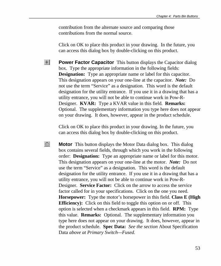
Chapter 4: Parts Bin Buttons
53
contribution from the alternate source and comparing thosecontributions from the normal source. Click on OK to place this product in your drawing. In the future, youcan access this dialog box by double-clicking on this product.
Power Factor Capacitor This button displays the Capacitor dialogbox. Type the appropriate information in the following fields:Designation: Type an appropriate name or label for this capacitor.This designation appears on your one-line at the capacitor. Note: Donot use the term “Service” as a designation. This word is the defaultdesignation for the utility entrance. If you use it in a drawing that has autility entrance, you will not be able to continue work in Pow-R-Designer. KVAR: Type a KVAR value in this field. Remarks:Optional. The supplementary information you type here does not appearon your drawing. It does, however, appear in the product schedule. Click on OK to place this product in your drawing. In the future, youcan access this dialog box by double-clicking on this product.
Motor This button displays the Motor Data dialog box. This dialogbox contains several fields, through which you work in the followingorder: Designation: Type an appropriate name or label for this motor.This designation appears on your one-line at the motor. Note: Do notuse the term “Service” as a designation. This word is the defaultdesignation for the utility entrance. If you use it in a drawing that has autility entrance, you will not be able to continue work in Pow-R-Designer. Service Factor: Click on the arrow to access the servicefactor called for in your specifications. Click on the one you need.Horsepower: Type the motor’s horsepower in this field. Class E (HighEfficiency): Click on this field to toggle this option on or off. Thisoption is selected when a checkmark appears in this field. RPM: Typethis value. Remarks: Optional. The supplementary information youtype here does not appear on your drawing. It does, however, appear inthe product schedule. Spec Data: See the section About SpecificationData above at Primary Switch—Fused.

Pow-R-Designer User Manual
54
Click on OK to place this product in your drawing. In the future, youcan access this dialog box by double-clicking on this product.
Emergency Generator This button displays the EmergencyGenerator Data dialog box. Type the appropriate information in thefollowing fields: Designation: Type an appropriate name or label forthis generator. This designation appears on your one-line at thegenerator. Note: Do not use the term “Service” as a designation. Thisword is the default designation for the utility entrance. If you use it in adrawing that has a utility entrance, you will not be able to continue workin Pow-R-Designer. KW Rating: Type a KW rating in this field.Remarks: Optional. The supplementary information you type heredoes not appear on your drawing. It does, however, appear in theproduct schedule. Click on OK to place this product in your drawing. In the future, youcan access this dialog box by double-clicking on this product.
Load This button indicates a “generic load” product in the system youhave drawn. For example, there is no lights ballast product in the Pow-R-Designer parts bin. Therefore, you would use the Load function.Place it in your drawing as you would other more specific products.This product is often attached to transformers. Designation: Type anappropriate name or label for this product. This designation appears inyour drawing at the product. Note: Do not use the term “Service” as adesignation. This word is the default designation for the utility entrance.If you use it in a drawing that has a utility entrance, you will not be ableto continue work in Pow-R-Designer. Voltage: Type the voltage youwant in this field Ampacity: Type the ampacity you want in this fieldShort Circuit:(see note on the short circuit field at switchboardproduct above): A value, based on previously supplied information,appears here after you run the short circuit program (see Calculationssection in Chapter 2). You can also type a value in this field. 1st Line,2nd Line: You can type identifiers or descriptors which indicate thetype of load. This information should consist of five characters or less inthese fields, and appears in your product. Remarks: Optional. The

Chapter 4: Parts Bin Buttons
55
supplementary information you type here does not appear on yourdrawing. It does, however, appear in the product schedule.
Deselect This button is less a product than a tool. Use it to stop theplacement process of a product whose button you clicked on in the PartsBin—but now don’t want to place. You use this option before youplace the product in the drawing space.


57
Chapter 5: Creating a One-LineDrawing—A Tutorial
Chapter 5 steps you through theconfiguration of a sample Pow-R-Designer one-line diagram (shown here). In this chapter you learn about:• Getting started• Parts-bin product placing• Editing• Calculations• Product schedules• Specification guide• Modifying text blocks• Adding Bitmap Images• Printing a drawing
Getting Started
If you have installed Pow-R-Designer, your Windows 95 Desktop orStart menu displays the icon or command you use to begin runningPow-R-Designer. (If you have not installed Pow-R-Designer, seeChapter 1: Pow-R-Designer Basics, page 1.) Double-click on theDesktop Pow-R-Designer icon or click on this command on the Startmenu. The default window appears.
To change the size of the drawing space, click on the drawing-size-control down arrow to select B, C, D, or E. The default size is A. Youcan change the drawing-space size at any time during the drawing
Figure 1: Refer to this drawing as you read theinstructions in this chapter.

Pow-R-Designer User Manual
58
process. The apparent size of your one-line does not change, but noticethat the scroll bars change size to indicate the difference.
The toolbar and parts bin buttons are arranged across the top of thePow-R-Designer window. Click on parts bin buttons to place productsin your drawing, and click on toolbar buttons to manage the drawing.These button groups are dockable; you can move them and reshapethem to station them where and how you want them. Click on the sideof one of these groups to relocate it; drag on a side to put it into adifferent form.
Save Your Work
Save frequently to protect your drawing and mitigate any problems youmay potentially encounter with computer malfunctions, softwareconflicts, or electrical outages. One of the more logical times to saveyour file is immediately after placing or reconfiguring a product.FBefore saving your drawing, run a short circuit program.
Save by clicking on the Save button on the toolbar, or by clicking onFile on the menu bar, then on Save. The first time you save a file, yousee the Save As dialog box. Use this box to name and assign your fileto the drive and folder you want.
Note: You should perform a short circuit program before saving orclosing a Pow-R-Designer one-line drawing. This practice ensures thatthe values displayed in the drawing are not obsolete, which would havethe potential for building an incorrect electrical system.
Qualification to This Tutorial
The core work of creating a one-line drawing—product placement—characterizes this section. Note, however, that technical aspects of thisprocess, such as determining which NEMA value to select or which kAto type in a field are not covered here. Your own determinations areconsidered the prime source for this kind of information. Provided hereinstead are ways to place products and navigate in Pow-R-Designer.

Chapter 5: Creating a One-Line Drawing—A Tutorial
59
General Drawing Strategy
Testing and actual field use of Pow-R-Designer have shown that a "fan-out" product-placement process works best in a drawing. In otherwords, attach larger products to the outside of their parent components,and group smaller products near the middle of those parent components.As a result of this strategy, products look like they fan out as you viewthe drawing overall. This strategy is suggested to mitigate the groupingof bigger products. If larger products group together, such groupingstend to choke pathways for smaller products and their associated cablewhich can result in awkward placements and overlaps.
Creating the Drawing
A. Place the utility entrance The drawing at the beginning of thischapter shows a tap into the utility which provides power to thiselectrical scheme, so place this product in your own drawing.Unlike other products, the utility entrance product naturally has noprovision for a designation or specification data since it is acommodity a contractor does not supply, but instead taps into. (Theutility entrance product does however have the designation“Service” assigned to it by default.)
1. Click on the Utility Entrance button in the parts bin.2. Click on the location in your drawing space where you want to place
the utility entrance. A dialog box appears.3. Using the down arrow, click on the voltage class and voltage you
need. A default value appears in the field X/R Source Ratio. Typea value in the field Source.
4. Click on OK to place the symbol for the utility entrance in yourdrawing, or click on Cancel to nullify your selections and return tothe drawing space.
The larger the drawing,the more significance thisstrategy acquires.

Pow-R-Designer User Manual
60
5. Save your work. FBefore saving your drawing, run a short circuitprogram. Read about saving under Save Your Work on theprevious page.
B. Place the fused primary switch1. Click on the Fused Primary Switch button in the parts bin.2. Click on a location for this product in the drawing space, typically
just below the utility entrance. A dialog box appears.3. Type a designation (label) for this product. The designation must be
unique—that is, not used for any other product in this drawing.4. Click on the down arrows at the KV and Load Break Ampacity
fields, respectively. Click on the values you want to apply to thisproduct.
5. Click on the down arrows at the Fuse Class, Fuse Type, and FuseAmperage fields, respectively. Click on the values you want toapply to this switch.
6. Type supplemental notes in the field Remarks, if necessary.7. Click on the Spec Data button to prepare information for a
specification guide. A Specification Data table appears.8. Type information under Value, according to what is called for in the
column labeled Attribute. Often, this information is acquired byclicking on a resident down arrow.
9. Click on OK to store the information in your file. It will be usedlater to create a specification guide for the current drawing. If youclick on Cancel, you erase the information you supplied and returnto the dialog box.
10. Click on OK to place the symbol for the fused primary switch inyour drawing, or click on Cancel to nullify your selections andreturn to the drawing space.
11. Save your work. FBefore saving your drawing, run a short circuitprogram. Read about saving under Save Your Work near thebeginning of this chapter.
C. Place cable It may be more efficient for you to place all productsin the drawing first, then connect them with cable later.
1. Click on the Cable button in the parts bin.
Do not use the designa-tion “Service” becausethis is used by default forthe utility entrance.

Chapter 5: Creating a One-Line Drawing—A Tutorial
61
2. Click on the bottom (downstream side) of the utility entrance.3. Click on the top (upstream side) of the fused primary switch. A
dialog box appears.4. Type a designation (label) for this product. The designation must be
unique—that is, not used for any other product in this drawing.5. In the section labeled Cable, click on the arrow by the Number of
Phases field and select the number of phases in the system.6. Next, click on the arrow by the Material field and select the material
type of the cable.7. Click on the arrow for the Cable Type field and choose the correct
current carrying conductors per cable.8. Click on the arrow by the Temperature field and select the
temperature corresponding to the cable you have chosen.9. Check the Include Neutral and Include Ground boxes if you would
like these options.10. Click on the arrow by the Neutral Rating field and select the
appropriate rating.11. Click on the arrow by the Conductor Type field and then on the
conductor type you choose.12. Type the number of feet your cable must run in the field Length.13. In the section labeled Conduit, click on the arrow for the field
Conduit Type and choose a type.14. You may need to provide supplemental information concerning this
run of cable. Type it in the field Remarks.15. Click on OK to place the symbol for cable in your drawing, or click
on Cancel to nullify your selections and return to the drawing space.16. Save your work. FBefore saving your drawing, run a short circuit
program. Read about saving under Save Your Work near thebeginning of this chapter.Note: You have the option of inputting all of the cable/conduit datamanually, or you can take advantage of the Automatic Cable &Conduit sizing option. This is as per the 1996 NEC cable andconduit fill tables based upon the downstream connection’sampacity. This is not to be substituted for sound engineeringpractices when sizing cable and conduit runs. (See Chapter 4,Cable Section)
D. Place a transformer

Pow-R-Designer User Manual
62
1. Click on the Transformer button in the parts bin.2. Click on a location in the drawing space where you want to place
the transformer, typically below the fused primary switch. A dialogbox appears.
3. Type a designation (label) for this product. The designation must beunique—that is, not used for any other product in this drawing.
4. Most of the available fields display down arrows to click on foraccessing values you can implement. Click on the values you needfor your job. The field Percent Z and the fields in the sectionComputed Values are driven by the other fields’ values. The field %Motor Load should be 100 because this is a service transformer.
5. Type supplemental notes in the field Remarks, if necessary.6. Click on the Spec Data button to prepare information for a
specification guide. A Specification Data table appears.7. Type information under Value, according to what is called for in the
column labeled Attribute. Often, this information is acquired byclicking on a resident down arrow.
8. Click on OK to store the information in your file. It will be usedlater to create a specification guide for the current drawing. If youclick on Cancel, you erase the information you supplied and returnto the dialog box.
9. Click on OK to place the symbol for a transformer in your drawing,or click on Cancel to nullify your selections and return to thedrawing space.
10. Save your work. FBefore saving your drawing, run a short circuitprogram. Read about saving under Save Your Work near thebeginning of this chapter.
E. Place cable The instructions in section C above are similar to theinstructions you need here. In this case, run the cable between theprimary switch and the transformer. Or, as mentioned in section C,you can place all products in the drawing first, then connect themwith cable later, if you wish.
F. Draw busway1. Click on the Plug-In Busway button in the parts bin.

Chapter 5: Creating a One-Line Drawing—A Tutorial
63
2. Click on a location in the drawing space below the transformerwhere you want to place the busway. The cursor, normally anarrow, becomes a cross-hair indicator.
3. Click once where you want to start drawing the busway. Draghorizontally across the screen to the desired busway endpoint. Dragvertically to further establish its position in your drawing. Clickagain to stop the busway drawing process. A dialog box appears.
4. Type a designation (label) for this product. The designation must beunique—that is, not used for any other product in this drawing.
5. Type the desired length, in feet, of the busway.6. Make selections in the remaining available fields by clicking on
options in the down-arrow lists. Select Feeder in the field Type forthis drawing because you are attaching cable to it. The fields R, X,and Z reflect driven, read-only values. The Short Circuit field is alsoderived, but you can type a value in it as well. Note: A value in thefield Short Circuit does not appear until you attach the product andrun a short circuit program.
7. Type supplemental notes in the field Remarks, if necessary.8. Click on the Spec Data button to prepare information for a
specification guide. A Specification Data table appears.9. Type information under Value, according to what is called for in the
column labeled Attribute. Often, this information is acquired byclicking on a resident down arrow.
10. Click on OK to store the information in your file. It will be usedlater to create a specification guide for the current drawing. If youclick on Cancel, you erase the information you supplied and returnto the dialog box.
11. Click on OK to place the symbol for busway in your drawing, orclick on Cancel to nullify your selections and return to the drawingspace.
12. Save your work. FBefore saving your drawing, run a short circuitprogram. Read about saving under Save Your Work near thebeginning of this chapter.
G. Place cable The instructions in section C above are similar to theinstructions you need here. In this case, run the cable between the

Pow-R-Designer User Manual
64
transformer and the busway. Or, as mentioned in section C, you canplace all products in the drawing first, then connect them with cable later,if you wish.
H. Place a motor control center1. Click on the MCC button in the parts bin.2. Click on a location below the busway where you want to place the
drawing. A dialog box appears.3. Type a designation (label) for this product. The designation must be
unique—that is, not used for any other product in this drawing.4. Make selections in the available fields in the upper portion of this
dialog box by clicking on options in the down-arrow lists. The fieldShort Circuit reflects a driven, derived value, but you can type avalue in it as well. Note: A value in the field Short Circuit does notappear until you attach the product and run a short circuit program.
5. In the Main Device section, click on the down arrow under Device.Click on the device you need for this product. The remaining cellsadapt according to your selection under Device.
6. Click on the down arrows or type information in the remaining cellsof this table. Your choices affect the availability of options in thesection Main Device Modifications.
7. Click on the options you need in Main Device Modifications.8. Click on the field Metering to display an MCC Metering dialog box
where you select the metering you want for the MCC. Click on OKto implement your selections or Cancel to exit without making anyselections.
9. Click on the button Add to place feeder devices in the MCC. A rowappears in the feeder breaker table.
10. Click on the down arrow in the cell under Device, then click on thedevice you need. As you do so, cell headers adapt to reflect thisselection. (Cell headers change as you move from row to row or asyou select different devices.)
11. Place information in each cell of this row. Either type thisinformation or select from a down-arrow menu. “N/A” means notapplicable—ignore these cells. Remarks are optional.
12. Click on the No/Yes button under Mods. A modifications dialogbox appears. Select the options you need, then click on OK. TheMCC dialog box appears. If you selected modifications, the button
Note: Cell or columnheaders (names) are notstatic, but change ac-cording to which device orrow is selected.

Chapter 5: Creating a One-Line Drawing—A Tutorial
65
under Mods becomes “Yes.” Click on this button if you want tochange your modifications.
13. Use the scroll bar for this table to access all cells.14. Place additional devices using steps 9–13 as a guide.15. Click on the Delete button to remove a row and its contents. Click
on the target row to select it.16. Note that the field Total HP reflects the sum of the horsepower of
the devices found in the feeder devices table.17. Click on the Spec Data button to prepare information for a
specification guide. A Specification Data table appears.18. Type information under Value, according to what is called for in the
column labeled Attribute. Often, this information is acquired byclicking on a resident down arrow.
19. Click on OK to store the information in your file. It will be usedlater to create a specification guide for the current drawing. If youclick on Cancel, you erase the information you supplied and returnto the dialog box.
20. Click on OK to place an MCC symbol in your drawing, or click onCancel to nullify your selections and return to the drawing space.
21. Save your work. FBefore saving your drawing, run a short circuitprogram. Read about saving under Save Your Work near thebeginning of this chapter.
I. Place cable The instructions in section C above are similar to theinstructions you need here. In this case, run the cable between thebusway and the MCC. Or, as mentioned in section C, you can place allproducts in the drawing first, then connect them with cable later, if youwish.
J. Place a switchboard1. Click on the Freestanding Switchboard button.2. Click on the location in the drawing space below the busway where
you want the switchboard to reside. A dialog box appears.3. Type a designation (label) for this product. The designation must be
unique—that is, not used for any other product in this drawing.4. Click on the field Rear Access if your specifications call for it.5. Make selections in the available fields in the upper portion of this
dialog box by clicking on options in the down-arrow lists. The field

Pow-R-Designer User Manual
66
Short Circuit reflects a driven, derived value, but you can type avalue in it as well. Note: A value in the field Short Circuit does notappear until you attach the product and run a short circuit program.
6. Click on one of the available devices in the Main Device section.7. If a row becomes available in the main device table, then click on the
down arrows, then on the selections you need for this product.Column headers adapt according to your radio button selection.
8. Your choices affect the availability of options in the section MainDevice Modifications.
9. Click on the options you need in Main Device Modifications.10. Click on the field Service Entrance when Main Lug Only is selected
to prevent (by regulation) the selection of more than six feederdevices for this product.
11. Click on the field Customer Metering to display a SwitchboardMetering dialog box where you select metering for the switchboard.Click on OK to implement your selections or Cancel to exit withoutselecting any metering.
12. Type the name of the power supplier in the field Utility Metering(optional).
13. In the Feeder Devices table, click on the down arrow in the cellunder Device, then click on the device you need. As you do so, cellheaders adapt to reflect this selection. (Cell headers change as youselect different devices or as you move from row to row.)
14. Place information in each cell of this row. Either type thisinformation or select from a down-arrow menu. “N/A” means notapplicable—ignore these cells. Remarks are optional.
15. Click on the No/Yes button under Mods. A modifications dialogbox appears. Select the options you need, then click on OK. Theswitchboard dialog box appears. If you selected modifications, thebutton under Mods becomes “Yes.” Click on this button if youwant to change your modifications.
16. Use the scroll bar for this table to access all cells, if necessary.17. Place three additional devices and two spaces using steps 12–16 and
Figure 1 as a guide. Make sure you include an HLD breaker.18. Click on the Spec Data button to prepare information for a
specification guide. A Specification Data table appears.
Note: Cell or columnheaders (names) are notstatic, but change ac-cording to which device orrow is selected.
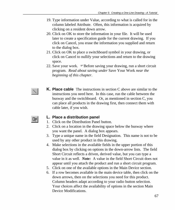
Chapter 5: Creating a One-Line Drawing—A Tutorial
67
19. Type information under Value, according to what is called for in thecolumn labeled Attribute. Often, this information is acquired byclicking on a resident down arrow.
20. Click on OK to store the information in your file. It will be usedlater to create a specification guide for the current drawing. If youclick on Cancel, you erase the information you supplied and returnto the dialog box.
21. Click on OK to place a switchboard symbol in your drawing, orclick on Cancel to nullify your selections and return to the drawingspace.
22. Save your work. FBefore saving your drawing, run a short circuitprogram. Read about saving under Save Your Work near thebeginning of this chapter.
K. Place cable The instructions in section C above are similar to theinstructions you need here. In this case, run the cable between thebusway and the switchboard. Or, as mentioned in section C, youcan place all products in the drawing first, then connect them withcable later, if you wish.
L. Place a distribution panel1. Click on the Distribution Panel button.2. Click on a location in the drawing space below the busway where
you want the panel. A dialog box appears.3. Type a unique name in the field Designation. This name is not to be
used by any other product in this drawing.4. Make selections in the available fields in the upper portion of this
dialog box by clicking on options in the down-arrow lists. The fieldShort Circuit reflects a driven, derived value, but you can type avalue in it as well. Note: A value in the field Short Circuit does notappear until you attach the product and run a short circuit program.
5. Click on one of the available options in the Main Device section.6. If a row becomes available in the main device table, then click on the
down arrows, then on the selections you need for this product.Column headers adapt according to your radio button selection.Your choices affect the availability of options in the section MainDevice Modifications.

Pow-R-Designer User Manual
68
7. Click on the options you need in Main Device Modifications.8. Click on the field Service Entrance when Main Lug Only is selected
to prevent (by regulation) the selection of more than six feederdevices for this product.
9. Click on the button Add to place feeder devices in the panel. A rowappears in the feeder devices table.
10. Click on the down arrow in the cell under Device, then click on thedevice you need. As you do so, cell headers adapt to reflect thisselection. (Cell headers change as you move from row to row or asyou select different devices.)
11. Place information in each cell of this row. Either type thisinformation or select from a down-arrow menu. “N/A” means notapplicable—ignore these cells. Remarks are optional.
12. Click on the No/Yes button under Mods. A modifications dialogbox appears. Select the options you need, then click on OK. Thedistribution panel dialog box appears. If you selected modifications,the button under Mods becomes “Yes.” Click on this button if youwant to change your modifications.
13. Use the scroll bar for this table to access all cells.14. Place an additional device using steps 9–13 and Figure 1 as a guide.15. Click on the Delete button to remove a row and its contents. Click
on the target row to select it first.16. Click on the Spec Data button to prepare information for a
specification guide. A Specification Data table appears.17. Type information under Value, according to what is called for in the
column labeled Attribute. Often, this information is acquired byclicking on a resident down arrow.
18. Click on OK to store the information in your file. It will be usedlater to create a specification guide for the current drawing. If youclick on Cancel, you erase the information you supplied and returnto the dialog box.
19. Click on OK to place a distribution panel symbol in your drawing, orclick on Cancel to nullify your selections and return to the drawingspace.
20. Save your work. FBefore saving your drawing, run a short circuitprogram. Read about saving under Save Your Work near thebeginning of this chapter.
Note: Cell or columnheaders (names) are notstatic, but change ac-cording to which device orrow is selected.

Chapter 5: Creating a One-Line Drawing—A Tutorial
69
M. Place cable The instructions in section C above are similar to theinstructions you need here. In this case, run the cable between thebusway and the panel. Or, as mentioned in section C, you can place allproducts in the drawing first, then connect them with cable later, if youwish.
N. Place a motor1. Click on the Motor button in the parts bin.2. Click approximately one inch below a switchboard space device. A
dialog box appears.3. Type a unique name in the field designation. This name is not to be
used by any other product in this drawing.4. Click on the down arrow in the field Service Factor. A menu
appears. Click on the option you want.5. Type a value in the field Horsepower.6. Click on the field Class E (High Efficiency) if your job calls for this
option.7. Type a value in the field RPM.8. Type supplemental notes in the field Remarks, if necessary. Such
notes do not appear in your drawing.9. Click on the Spec Data button to prepare information for a
specification guide. A Specification Data table appears.10. Type information under Value, according to what is called for in the
column labeled Attribute. Often, this information is acquired byclicking on a resident down arrow.
11. Click on OK to store the information in your file. It will be usedlater to create a specification guide for the current drawing. If youclick on Cancel, you erase the information you supplied and returnto the dialog box.
12. Click on OK to place the symbol for a transformer in your drawing,or click on Cancel to nullify your selections and return to thedrawing space.
13. Save your work. FBefore saving your drawing, run a short circuitprogram. Read about saving under Save Your Work near thebeginning of this chapter.
O. Place cable The instructions in section C above are similar to theinstructions you need here. In this case, run the cable between the

Pow-R-Designer User Manual
70
spacer device and the motor. Or, as mentioned in section C, youcan place all products in the drawing first, then connect them withcable later, if you wish.
Editing
Use editing functions to modify sections of your drawing. Thesefeatures include Cut, Copy, Paste, Delete, Find, DisconnectCable/Feeder Busway, Resize Busway, Disconnect Busway, and Font.Moving products is also an available function, but you don’t use theEdit menu for this.
You can access editing commands by:
• Clicking on a toolbar button,∗
• Clicking on Edit on the menu, or• Right-clicking in the drawing space.Note: Before using the commands Cut, Copy,Delete, Disconnect Cable/Fdr Busway, ResizeBusway, and Disconnect Busway, you mustselect a product. You can also select multipleproducts using Shift or Ctrl with clicking.
Cut, Paste, Delete Cut the motor from its location under the spacedevice and relocate it under the HLD breaker in the switchboard; deletethe motor’s cable and redraw it.
1. Click on the motor in your drawing.2. Click on Cut. This stores the motor on the clipboard.3. Click in the drawing space about one inch below the HLD
breaker.4. Click on Paste. The motor appears. Note: The Cut and Paste
functions do not apply to cable.5. Click on the cable extending below the space device.6. Click on Delete. This removes the cable permanently.7. Place a cable between the motor and the HLD breaker according
to section C above. ∗ The toolbar does not include these editing commands: Disconnect Cable/Feeder Busway, ResizeBusway, Disconnect Busway, and Font.

Chapter 5: Creating a One-Line Drawing—A Tutorial
71
Move, Resize Busway, Copy Move the switchboard to a lowerposition on the drawing; move the distribution panel to the left; copy themotor control center to a location on the right.
Move1. Click on the switchboard without releasing the mouse button.2. Drag the switchboard down about an inch.3. Click on the distribution panel without releasing the mouse
button.4. Drag the distribution panel left to a position above the
switchboard. Note: The Move function does not apply to cable,although cable remains connected to a moved product.
5. Click on the cable connecting the distribution panel to thebusway.
6. Click on delete. The cable is permanently removed.7. Place a cable between the busway and the distribution panel
according to section C above.Resize Busway1. Click on the busway.2. Click on Resize Busway. If you have a color monitor, you see
the busway become a different color and acquire coloredendpoints.
3. Drag the right-hand busway endpoint to the right about an inch.The busway returns to its former color.
4. Click in the drawing space away from a product to deselect thebusway.
Copy1. Click on the motor control center.2. Click on Copy.3. Right-click where you want to place the MCC. An edit menu
appears.4. Click on Paste. The copied MCC appears.5. Move the MCC to a position to the left of the distribution panel
and below the busway.6. Place a cable between the busway and the distribution panel
according to section C above.

Pow-R-Designer User Manual
72
Find, Disconnect, Reconnect Plug-In Busway For the sake ofseeing how these functions work in Pow-R-Designer, perform thefollowing edits:
Find1. Click on the Find button. A Find dialog box appears.2. Click on the name (designation) of the plug-in busway that you
placed in your drawing.3. Click on OK. The busway becomes outlined (selected) in your
drawing. You could move it, copy, change its specifications,etc., as you would any selected product.
Disconnect Plug-In Busway1. The busway is already selected; no need to click on it.2. Click on Edit on the menu bar, then on Disconnect Busway.
Connection points between the busway and cable disappear.Reconnect Plug-In Busway:1. Click on the busway without releasing the mouse button.2. Move the busway slightly.3. Click in the drawing space away from a product to deselect the
busway. The connection points reappear on the busway.
Disconnect Cable/Fdr Busway Disconnect the cable from oneproduct and connect it to another.
1. Add a panelboard to your drawing. Place it under the buswayto the right of the distribution panel.
2. Select the cable connecting the distribution panel to the buswayby clicking on it.
3. Click on Disconnect Cable/Fdr Busway and select DownstreamConnection by clicking on it in the dialog box. The cable fromthe busway is now disconnected from the distribution panel.
4. Click the downstream end of the cable with your mouse anddrag the cable to the new panelboard. The cable now connectsthe busway and the panelboard.
Note: This Edit function can disconnect a cable or feeder buswayfrom the upstream product, downstream product, or both.
Performing Calculations

Chapter 5: Creating a One-Line Drawing—A Tutorial
73
The calculations you use with Pow-R-Designer drawings are UpdateVoltages, Short Circuit Program, and Consistency Check. Thesecommands appear under Calculations on the menu bar. (See side noteon nominal voltage, typical load current, and voltage drop in theSchedules section of Chapter 2.)
Update Voltages Click on Calculations on the menu bar, then onUpdate Voltages. Your drawing reassesses existing voltages at eachproduct after you make any additions or revisions. A voltage dropcalculation is also performed in this step.
Short Circuit Program Click on the Short Circuit button (or onCalculations on the menu bar, then on Short Circuit Program) tocalculate available short circuit fault current. By default, this value isdisplayed in red kA values next to each product’s node.
Consistency Check Click on Calculations on the menu bar, then onthe command Consistency Check. This function determines whetherdevices upstream and downstream from transformers are the correctsizes. You receive an on-screen report on the status of your system.Make adjustments in the indicated areas if necessary.
Creating Schedules
Create a product schedule and create a name for it at the Schedulesmenu. (Read about exporting schedules to spreadsheets, underSchedules in Chapter 2.)

Pow-R-Designer User Manual
74
Prepare SchedulesClick on Schedules on themenu bar, then on PrepareSchedule. A dialog boxappears. Click on theproducts you want toappear in your schedule.If you want to choose allproducts, click on thebutton Check All. If youwant to remove allcheckmarks from thisdialog box, click on Uncheck All. Click on OK. A table appears thatdisplays the specifications of the products you selected.
Set Schedule Title While your schedule is still displayed, click onSchedules on the menu bar, then on Set Schedule Title. A ScheduleTitle dialog box appears. Type a name for the current schedule in thefield provided, then click on OK. This name does not appear on yourscreen, but does appear at the top of the schedule when you print it out.
Print Schedules While your schedule is still displayed, click on Fileon the menu bar, then on Print. A Print dialog box appears which youcan use to choose print options. Click on OK to send this job to theprinter. If you have not named your schedule (see Set Schedule Titleabove), the printout is named “Pow-R-Designer Schedule.”
Change Schedule Column Sizes Some cell text and columnheader names are long enough to be partially out of view. To see thisinformation, you can widen the columns. To do so, position the cursoron a partition between columns at the top of the schedule. When thecursor becomes a double line with arrows (see picture here), click anddrag the partition until the column is the size you want.
Close Schedules Two ways to close the schedule window are:• Click on Window on the menu bar, then click on the name of the
current drawing. This method of schedule closing leaves theschedule active in the background. You can access the schedule at
Saving a schedule: Whileyour schedule is displayed:1. Select all columns (you
can also select fewer).2. Press Ctrl+C.3. Open a new file in a
spreadsheet application.4. Press Ctrl+V.5. Save the file.See also Exporting aSchedule to a Spreadsheetin Chapter 2.
Run a voltage update anda short circuit programbefore creating aschedule.
Once you have created aschedule, look in its Cablesection for nominalvoltage, typical load cur-rent, and voltage dropvalues.

Chapter 5: Creating a One-Line Drawing—A Tutorial
75
any time by clicking on Window on the menu bar, then on the nameof the schedule.
• Save your schedule (see sidenote at left) first, if desired. Then clickon the Close button on the menu bar. This removes the schedulefrom activity and from the screen. The current drawing appears.To access the saved schedule for this drawing again, click on File onthe menu bar, then on Open. A dialog box appears. Click on thefolder and file name where you saved the schedule.
Creating a Specifications Guide
Create a specifications guide from the information you provided atproduct dialog boxes when you clicked on the Spec Data button.1. Click on File on the menu bar, then on Export.2. Click on Spec Guide. A dialog box appears prompting you to save
this file in the location of your choice.3. Click on OK. Pow-R-Designer creates an *.rtf specifications guide
file which you can read with your word processing program.4. Access this file by clicking on File, then on Open. Click on the
target folder and file.
Modifying Text Blocks
1. You can modify the positioning of the text associated with eachcomponent shown on the one line diagram by simply selecting theproduct, by click on it once, then right clicking with your mouse,and selecting either Move System Text or Move Display Text.
Adding Bitmap Images
1. You can add a bitmap image to your drawing by first choosing thearea on your drawing by maneuvering the mouse pointer to thatlocation, right click on your mouse and then selecting AddBitmap.
Spec Data button: SeeAbout Specification Datain Chapter 4 under UtilityEntrance.

Pow-R-Designer User Manual
76
Printing a Drawing
1. Select the print size you want (see step 2, “Select a size for yourprintout” in the section Creating a Drawing—Overview in Chapter1).
2. Click on File on the menu bar, then on Print. A dialog box appears.3. Click on the Properties button to see ways to modify your printout,
then click on the OK button to return to the Print dialog box.4. Click on the options you need.5. Click on OK to print the drawing.
Use this control to selecta size for your printout.

77
Index
# Phases field, 37% Fully Loaded field, 38% Motor Load field, 38.dxf, 8.pd, 11.rtf, 8.txt, 81, 2, 3...files, 14, 261st Line field, 512nd Line field, 51about
cable, 44downstream panelboard connections, 42feeder busway, 45panelboards, 44Pow-R-Designer, ix, 27saving, 10schedules, 19specification data, 36
accessing product dialog boxes, 36, 37, 38, 40,41, 42, 43, 44, 45, 46, 47, 48, 49, 50
Amp Rating field, 48, 49Ampacity field, 51
fused disconnect switch, 45nonfused disconnect switch, 46
Arrange Icons, 26arranging multiple views, 26Auto Name
feeder devices, 39AutoCAD, 11Auto-Change tab, 24automatic transfer switch, placing, 48basics
Pow-R-Designer, 1Branch Devices (table), 42breaker modifications, 42breaker substitution, 22Bus Bracing field, 42busway
feeder, creating, 6
feeder, instructions, 44plug-in, creating, 6plug-in, disconnecting, 16, 68plug-in, instructions, 44plug-in, product connection, 7plug-in, reconnecting, 68plug-in, resizing, 16plug-in, tutorial, 58
button group (toolbar or parts bin), 5cable
connecting, 6note, 44running, 43tutorial, 56
CAD, exporting to, 8, 11calculations, 21, 33
options, 23performing, 7tutorial, 68
capabilities of Pow-R-Designer, ixCascade, 26Change Items dialog box, 22changing font of drawing, 16Check All button, 19Class E (High Efficiency) field, 50clipboard, 14, 15, 31, 32close
drawing, 10drawing (see step 2), 30Pow-R-Designer, 14schedule, 8, 70
combination starter, placing, 48command descriptions, viewing, 17Component tab, 24computer requirements, 1configuring
placing products, 5toolbar/parts bin button groups, 29
connectingbusway (plug-in) and products, 7

Pow-R-Designer User Manual
78
cable to products, 6products, 6
Connection column, 42Connections section (cable), 44consistency check
button, 33command, 23tutorial, 68
context sensitive help, 34copy
button, 32feeder devices, 39multiple products, 32product, 15, 32, 67
copyright, 27, 34creating
busway (feeder), 6busway (plug-in), 6drawing—overview, 4file name, 4one-line (new), 29sample drawing (tutorial), 53schedule, 69
Customer Metering field, 39cut
button, 31column (schedule), 20multiple products, 32product from drawing, 14, 31, 66
Default Namefeeder devices, 39
default window, Pow-R-Designerdetailed, 3
deletebutton, 33multiple products, 33product, 15, 33, 66
Deselect button, 51Designation, 36, 37, 39, 40, 41, 42, 45, 46, 47,
48, 49, 50, 51Designation list (Find), 16Devices table (MCC), 43dialog box fields, grayed out/
inaccessible/dimmed, 34Disconnect Busway, 16
Disconnect Plug-In Busway, 68disconnect switch
fused, placing, 45nonfused, placing, 46
displayhidden drawing, 9, 14, 30hidden icons, 26hidden window, 26Options, 24parts bin, 18status bar, 17toolbar, 17
distribution panel, wall mountedplacing, 40tutorial, 63
docking the toolbar/parts bin, 5, 29downstream product, 6drag-select, 6drawing
creating (overview), 4creating new, 29export, 8mailing, 12, 31opening, 30print size, 3printing, 30size, 3space, 3strategy, 8, 55zoom, 18
drawing spaceprintout size, 53
duplicating a product, 32Duty field
fused disconnect switch, 45nonfused disconnect switch, 46
editfunctions (tutorial), 65products, 7, 14
Edit menu, 14Electrical Interlock field
fused disconnect switch, 45nonfused disconnect switch, 46
Emergency Generator, placing, 50Enclosed Breaker, placing, 46

Index
79
Enclosure Type fieldautomatic transfer switch, 49enclosed breaker, 47fused disconnect switch, 45nonfused disconnect switch, 46
Existing (1, 2, 3...) file, 26Existing files, 14exit
Pow-R-Designer, 14Export, 8
drawing, 8, 11schedules to spreadsheet, 20
extension.pd, 11dxf, 8rtf, 8txt, 8
Fans field, 38features of Pow-R-Designer, 3feeder busway, 44
note, 45feeder devices
Auto Name, 39copy, 39Default Name, 39paste, 39
Feeder Devices tabledistribution panel, 41freestanding switchboard, 40
fields, grayed out/inaccessible, 34File menu, 9File Open dialog box, 9File Save As dialog box, 11files at Window menu, 26find
(search for) products, 7, 16, 33button, 33dialog box, 16products, 16, 33tutorial, 67
fontchanging, 7, 16command, 16
Frame Amps field, 47freestanding switchboard
placing, 39tutorial, 61
Fuse Amperage field, 37Fuse Amps field, 45Fuse Class field, 36Fuse Clip field, 45Fuse Type field, 36fused disconnect switch, placing, 45fused primary switch
placing, 36tutorial, 56
grayed out dialog box fields, 34Ground Lug field
fused disconnect switch, 45nonfused disconnect switch, 46
Help, 26Help button, 34Help, Using (command), 27hidden
drawing, displaying, 9, 14, 30icons, displaying, 26window, displaying, 26
hints on Pow-R-Designer, 26Horizontal Bus field, 43Horsepower field, 50inaccessible dialog box fields, 34Incoming Cable section, 43Index, for Help, 27individual contactor, placing, 48installation, Pow-R-Designer, 1Integral Overcurrent Protection field, 49Internet, Pow-R-Designer and, 27joining products, 6joining products to plug-in busway, 7killing Quick mode, 34KV field
fused primary switch, 36nonfused primary switch, 37
KVA field, 38KVAR field, 49KW Rating field, 50label, product, 7Load Break Ampacity field
fused primary switch, 36nonfused primary switch, 37

Pow-R-Designer User Manual
80
Load button, 50mail drawing, 12, 31Main Bus Rating field
distribution panel, 40freestanding switchboard, 39panelboard, 41
Main Device Modifications sectiondistribution panel, 40freestanding switchboard, 40MCC, 43panelboard, 42
Main Device sectiondistribution panel, 40freestanding switchboard, 39MCC, 43panelboard, 41
MCCplacing, 42tutorial, 59
menu barcommands, 9definition, 3
Metering field, 43mode, Quick, 6, 18, 34Model field, 47Mods cell, 42Mods column, 40motor
placing, 50tutorial, 64
motor control centerplacing, 42tutorial, 59
motor load contributions of transformers inshort circuit calculations, 23
moveproduct, 7toolbar/parts bin, 5, 29tutorial—products, 66
multiple drawing views, arranging, 26multiple products
copying, 32cutting, 32deleting, 33drag-select, 6
selecting, 6, 14, 15naming a schedule, 19NEMA Size field
combination starter, 48noncombination starter, 47
NEMA Type field, 42NEMA Wiring field, 43nested product, 15, 32Neutral Kit field
fused disconnect switch, 45nonfused disconnect switch, 46
New Drawingbutton, 29command, 9
New Message dialog box, 12New Window, 26nominal voltage, 19noncombination starter, placing, 47nonfused disconnect switch, placing, 46nonfused primary switch, placing, 37notable features of Pow-R-Designer, 3note
on cable, 44on feeder busway, 45on motor load contributions of transformers
in short circuit calculations, 23on nested product, 15, 32on panelboard connections, 42, 44on Short Circuit field, 38on spec data, 36
nullifying Quick mode, 34numbered files, 14open
button—drawing, 30drawing, 9, 30Pow-R-Designer, 2
Options, 23Panel Feeders dialog box, 42, 44panelboard
connections note, 42, 44placing, 41
parts binabout, 3buttons, 35display, 18

Index
81
docking, 29moving, 5
pastebutton, 32feeder devices, 39product, 15, 32products (tutorial), 66
Percent Fully Loaded field, 38Percent Motor Load field, 38Percent Z field, 38performing calculations, 7Phase/Wire field, 49placing
products, 5, 35products quickly, 6, 18, 34
plug-in buswaydisconnecting, 16resizing, 16running, 44
Poles fieldautomatic transfer switch, 49enclosed breaker, 47fused disconnect switch, 45individual contactor, 48nonfused disconnect switch, 46
power factor capacitor, placing, 49Pow-R-Designer
about, ix, 27basics, 1capabilities, ixclosing, 14copyright, 27features to note, 3hints, 26installation, 1Internet, 27notable features, 3opening, 2requirements, 1tips, 26version, 27, 34web page, 27
Pow-R-Line field, 41Prepare Schedule, 19preparing to draw, 53
Primary Full Load Amps field, 38primary switch
fused, placing, 36nonfused, placing, 37
Primary Voltage field, 37print
button, 30command, 12dialog box, 12, 30drawing, 30, 71properties, 13, 31schedule, 69tutorial, 71
Print Preview command, 13Print Setup
command, 13dialog box, 13
Print to File field, 12, 31printout
sizing, 5product
connecting to cable, 6connecting to feeder busway (see step 6), 6connecting to plug-in busway, 7connecting/joining, 6copying, 15, 32cutting, 14, 31deleting, 15, 33deselect, 14drag-select, 6duplicating, 15, 32editing, 7, 14finding, 7, 16, 33inside larger product, 15, 32label, 7moving, 7nested, 15, 32pasting, 15, 32placing, 35schedule, 8schedules, 19searching for, 7, 16, 33Select All, 6, 16select from parts bin, 18selecting, 6, 14

Pow-R-Designer User Manual
82
stuck inside another product, 15, 32Product Information, 34properties, print, 13, 31qualification to tutorial, 54Quick mode, 6, 18, 34
nullifying Quick mode, 34Rated Voltage field, 49Rating field, 41Rear Access field, 39Recommended Primary Protection Device
field, 38Recommended Secondary Protection Device
field, 38Reconnect Plug-In Busway (tutorial), 68Remarks, 36, 37, 38, 41, 45, 46, 47, 48, 49,
50, 51remove (from display)
parts bin, 18status bar, 17toolbar, 17
requirements for Pow-R-Designer, 1Resize Busway command, 16resizing plug-in busway (tutorial), 67right-clicking (to edit), 7running
busway (feeder), 44busway (plug-in), 44cable, 43
Sales Offices, inside front cover, 27sample drawing (tutorial), 53save
about, 10button, 30displayed drawing, 30schedule, 20, 70
Save As, 4, 11schedule
about, 19button, 33changing column sizes, 21, 69closing, 8, 70creating, 8, 69dialog box, 19exporting to spreadsheet, 20options, 25
preparing, 69printing, 69removing a column, 20saving, 20, 70titling, 69tutorial, 69
searching for products, 7, 33Secondary Full Load Amps field, 38Secondary Voltage field, 38select
multiple products, 15products from parts bin, 18
Select All, 6, 16selecting
all products, 6area of drawing, 6multiple products, 6, 14overview, 6product, 14products, 6
service entrance, 5Service Entrance field, 49
distribution panel, 40freestanding switchboard, 39
Service Factor field, 50Set Schedule Title, 19shaping the toolbar/parts bin, 29short circuit, 41
analysis, 21, 33fault current, 21, 33field, note on, 38footnote, 39Program, 21, 33
Short Circuit fielddistribution panel, 40enclosed breaker, 47freestanding switchboard, 39fused disconnect switch, 45load product, 51MCC, 43nonfused disconnect switch, 46
Short Circuit Program, 21, 68size
A-B-C-D-E, 5drawing, 3

Index
83
drawing space, 53printout, 5
Source field, 36Spec Data, 8, 37, 38, 40, 41, 42, 43, 44, 46,
47, 48, 49, 50about, 36button, 36
Spec Guide (Export command), 11specification data, about, 36specifications guide
creating, 8tutorial, 70
spreadsheet, exporting schedules to, 20starter, placing, 47, 48status bar display, 17storing, product on clipboard, 31strategy for drawing, 8, 55stuck product (inside another product), 15, 32support, Pow-R-Designer, 27Switch Type field, 49switchboard
freestanding, placing, 39tutorial, 61
System Voltage field, 42technical support, 27Temperature Rise field, 38Tile, 26Tip of the Day, 26title
block, 25schedule, 19
title blockremoving, 25tab, 25
title block features, 4toolbar, 4
buttons, 29display, 17docking, 29moving, 5
toolbar/parts bin moving, 5Total HP field, 43transformer
placing, 37tutorial, 57
Trip Amps field, 47tutorial
busway, plug-in, 58calculations, 68chapter, 53consistency check, 68copying products, 67creating schedules, 69creating the drawing, 55cutting products, 66deleting products, 66disconnecting plug-in busway, 68editing, 65finding products, 67moving products, 66pasting products, 66placing busway, plug-in, 58placing distribution panel, 63placing fused primary switch, 56placing MCC, 59placing motor, 64placing service, 55placing switchboard, 61placing transformer, 57placing utility entrance, 55Pow-R-Designer, 53printing a drawing, 71qualification, 54reconnecting busway, 68resizing plug-in busway, 67running cable, 56schedule, 69Short Circuit Program, 68spec guide, 70titling schedule, 69updating voltages, 68
tutorial on Pow-R-Designer (sample drawing),53
Type field, 37typical load current, 19Uncheck All button, 19Unit Mounting field, 43Update Voltages, 21, 33, 68upstream product, 6Using Help command, 27

Pow-R-Designer User Manual
84
utility entranceabout, 5button, 35tutorial, 55
Utility Metering field, 39Value column, 8version of Pow-R-Designer, 27, 34View menu, 17viewing command descriptions, 17Voltage Class field, 35voltage drop, 19voltage drop calculation, 21, 23, 68Voltage Drop tab, 23Voltage field, 51
distribution panel, 40enclosed breaker, 47freestanding switchboard, 39fused disconnect switch, 45nonfused disconnect switch, 46panelboard, 41utility entrance, 36
voltage update, 21, 33, 68wall mounted distribution panel
placing, 40tutorial, 63
web page, Pow-R-Designer, 27Window (on menu bar), 26X/R field, 38X/R Source Ratio field, 36zoom drawing, 18

85