pour, cloud, and flash point testing with various blends...
TRANSCRIPT
Pour, Cloud, and Flash Point Testing with
Various Blends of Soy Diesel
Date conducted: Spriny semester 1935 Complered b!.: Michael C. Hail Supemised bjr: Dr. Joseph .A. Wehrmeyer
Dr-. Lzon Schumacher Dr. Mark Russell

PROJECT SmIMARY
This lab experiment shows data gathered from experiments completed in the spring semes- ter of 1995. The data gather is for flash, cloud, and pour points for various blends of soy diesel with $2 diesel fuel. The cloud point results show a linear path. The flash points fall below a linear path of a straight line graphed from 0% soy diesel to 90% soy and 10% K diesel for the various biends of spy diesel. From the pour point data gathered, it was found that the ,pour point below a 30% so>’ diesel and 70% #2 diesel fuel blend was below -25 “F.

PROJECT DESCRIPTION
1. JI’iiRODUCTION
BioDiesel is a fuel that could change the way petroleum fuels are noa’ observed. BioDiesel can be made from a large variety of feedstocks, including but not limited to recycled vegetable oils from the food service industry, soybean oil. and other inedible and edible oils and greases can be used (Lee, 4). For every unit of energy it takes to make soy diesel, including the planting, harvest- ing and actual fuel making process, the sov diesel give two units of enera-. Chemical fats are complex organic uiestersr!z-rown as tri-gl$ceride, obtained from univalent alcohol’s and glycerol combinations (Lee. 7). Depending on the t\pe of feedstock used, the type of esrer formed varies. If a renewable aticultural product IS used, the ester created in the esterification process is an ethyl ester. However,-if a methyl ester is formed, it would most likely be from petroleum products used in the esterification process (Lee, 10) Transesterification is a chemical process that involves the reaction of a renewable oil with alcohol in the presence of a catalyst. The resulting mixture sepa- rates into fatty acid esters and glycerol. Sometimes, the esterified oii can be skimmed off the top, but in most instances, the esterified oil becomes acidified or alkaline and could cause significant corrosion and wear on an engine if it is not washed before blending. The washing of the oil with water neutralizes the acid or alkaline part of the ester-i&d mixture. The amount of acid or alkaline part of the solution is highly variant on the process by which it is made (Lee, 9).
Testing has been going on for some time on BioDiesel. The need for BioDiesel in industry is being motivated by the Clean Air Act (Lee, 5). Early testing indicated that Biodiesel may work , as a one hundred percent substitute, or that it can be used in a blend with the Icurrent diesel fuels on : the market. Previous BioDiesel testing suggests that it burns much cleaner than #2 diesel fuel (Lee, 6). However, it is more expensive to produce than petroleum fuels. Pure BioDiesel contains a minimal amount of sulfur and aromatics. which cause most of the air pollution commonly asso- ciated with peuoleum fuels (Lee, 4). The current consumption of diesel fuel on the market could b>, no means be replaced totally by BioDiesel. but BioDiesel could be used in large cities to sig- mficantly reduce air pollution problems.
The characteristics of blending BioDiesel with +2 diesel fuel was our focus for this study. The specific type of BioDiesel used for these experiments was soy diesel. uhich is produced from so!- oil from soy bsans.
The flash point. cloud point, and pour point are the oil properties that are discussed in this report. Flash point is the lowest temperature corrected to a baromehic pressure of one atmosphere, at which application of a test flame causes the lrapor of a specimen to ignire under specified condi- tions (ASTM D93. 29). The flash point measures the tendenclr of the sample to form a flammable mixture with air under controlled laboratory conditions (.GTM D93,29). Goud point is the tem- perature at which a cloud of wax crystals first appear in a liquid when it is cooled under special testing conditions (ASTM D 2500,883). The cloud point of a petroleum product is an index of the lowest temperature of its utilinr for certain applications (.GTM D 2500. 883 )_ The pour point is the lowest temperarure at which movement of the oil is observed (ASTIM D 97. 57). The pour
- point is an index of the lowest temperature of its utiliQ- for certain applications (.GTM D 97. 57).
Testing vrzs conducted on different blends of me two types of fueis. The tests were con- ducted at MF.A Oil Laboratories in Columbia. MO, undo the supenvision oFPhilip Kell!~. by Michael Hall usins the standard .4STM testing procedures.
The blending procedure was completed on a volume basis. Blending. in the report is based on the amount of so!’ diesel in the blend. such as a -0 3 ?& blend would mean 2OSb so!’ diesel and

80% $2 diesel. The tests are categorized into flash point and cloud and pour point tests. The cloud and pour point tests are categorized together as the tests were completed using the same sample and testing apparatus.
The overall purpose of this research was to develop a relative sense for the cioud, pour, and flash points for various blends of Biodiesel. Specifically, the objectives of the research were that by doing research in this area, researcher; on Biodiesel will be able to decide the most efficient cold weather operation blend of soy diesel for use in industry. The research done will help one to see thar a blend of sov diesel with #2 diesel fuel will be almost as versatile as $ diesel fuel, but wiIl significantly reduce air pollution and help to meet the nem. more stringent emission standards the U.S. is placing on fuel market. In this project, the intenr is to perform experiments to gain knowl- edge of properties of various blends of soy diesel with $2 Diesel fuel. The tests were used to obtain temperature values for these points for the various blends. The data generated from these tests will help with the decision of what the most useful blends for efficient use in industry are.
3. E>XPERIMEXTAL PROCEDURES
3.1 Sample Fuels Used
The samples were blends of soy diesel (a type of BioDiesel) and X2 Diesel fuel. The blends ranged from zero to one hundred percent soy diesel. The diesel fuel used was clear, win- terized #2 diesel with a cold flow improver (Kelly).
!,
3.2 Experimental Equipment
3.2.1 Flash point test equipment
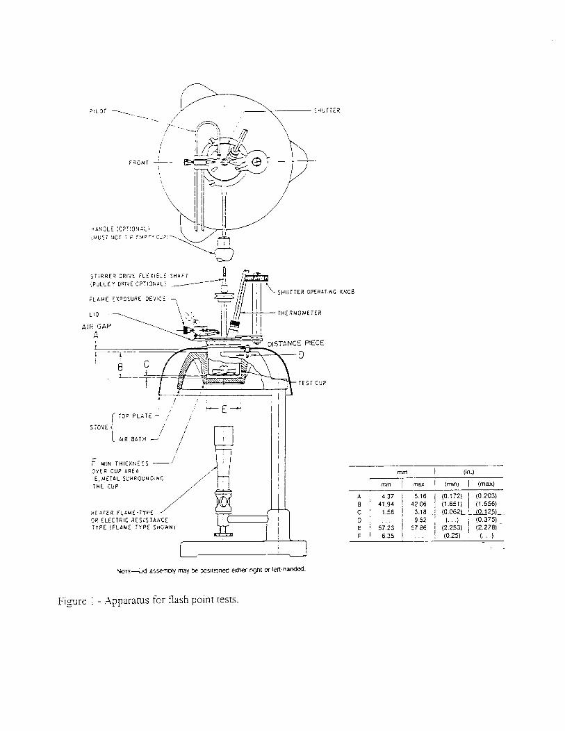
A Pensky--Martins Closed Flash Tester was the main piece of equipment used for the flash point test. The flash tester has many parts and the way. it is constructed is completely per ASTM apparatus specifications (figure I), tn the appendix of this report a copy of the specifications are given. .4 thermometer with a scale of 20 to 230°F was used as per ASTM procedure (ASTM D93, 29).
3.2.2 Cloud and pour point tests equipment
A controlled temperature cold air bath was used for the cloud and pour point tests. The air bath had three different baths at three different temperatures. 30: 0. -30°F. .Z thermometer was used for every sample. A special test jar was used with dimensions as per .X334 procedure (ASTh4 D 97, 57). Other equipment needed was a cork to best fit the special jar, a cork gasket to fit around the jar. and a jacket that is-in the cooling bath. and a piece of cork to lay at the bottom of the jacket. a diagram of the apparatus and equipment is ,oi\ren below. in Figure 2.
3.2.3 !Vixing equipment
.4 100 ml nduated cylinder uith one mL increments was used for the mixin! of the fuels. .A plunger thar fit in the top of the flask was used for the actual mixing procedure. Fuel holdins conrayners were used to hold the several gallons of the two types of fuels used.
rlEdrEi3 FLAME-TYFE OR ELECTRIC RESIST’NCE :TPE LFCAuf TYPE SM.?WI
-.
Fi-are 1 - Apparatus for flash point tests

COOLING BATH -
Figure 2 - Apparatus for pour point tests.
3.3 Measurement Procedures and ,Methods
33.1 General mixing procedures
The mixing was all completed on a volume basis, in a 100 mL flask. ‘The contents were poured together, then a plunger was inserted into the top of the flask and the flask was overturned at least 5 times to insure complete mixing of the two fueIs.
3.32 Flash point procedures
The blends were tested for flash point. The flash point test needed 65 mL of blended fuel to complete one test. The fix1 was poured into a brass test cup, then inserted into the holder on the Pensky-Martens Closed Tester. The tester had a built in heater that heated the fuel at a controllable rate. The slower the heating rate the better the resuIts. The temperature of the fuel was monitored with a thermometer. The f%els flash point was checked at three degree intervals by turning a handle that opened the top of the tester and simultaneously inserted a flame into the t?p of the cup. If the temperature of the fumes in the cup was high enough the fuel would ignite, but If not, noth- ing would happen. The turning of the handle was completed every three degTees once the sample

was close to reaching the flash point until the fuel ignited. The fuel sample was then taken from the tester and disposed and the inside of the cup was cleaned with a rag? then the tester was readied for the next test.
3.3.3 Cloud and pour point procedures
The blends of fuel were checked at 10% intm!als, starting with 100% and going to 0% blend. The process for each of these test started by mixing the fuel. The fuel then was poured into a special testing jar (see .4STM procedure for specifications). The jar was filled approximately
Fuel o/o blend Cloud point (deg F) Pour point (dea F) : Flash Point (dea F) I 0 -3 j -2; -1:’ - * : 143 142' 141 I
10 4 i 4: 41' * l 141 148 146 :
13 ! i ~ 146 145 146 1
15 /
i
j 133 140 147 j j I
17 I I
20 I 21 2i 3i* - I * 1 301 51
41 4i+ f I
l
I I
40 j 8 81 71 -14 -12 I
j x&--q
/ 158 158
501 6 61 91 1’ Oi 1/ 1651 165 / 163
601 121 16' 121 9 81 8 j 172 1 180 1 170 I
70 1 171 161 151 12 11.5 j 12! 183' 183 181 1 I 80 I 18 / 191 20/ 16 171 15) I 90 23.5 i / 24 : 23 1 20 20.5 I 20 j
100 26 j 26 311 24 23.5 : 24 I ff
230&i 200!
No data was taken on all blank areas * pour point below -25F
** Flash point above 230F
Table 1 - Data obtained from tests
54 mm above the bottom of the jar with the test fuel blend, mrhich was approximatelv 40 rnL of test fuel. This jar then had a cork inserted into the top of the flask: which had a thermoieter in it. A piece of cork xas applied to the outside of the jar to act as a washer so the sides of the special jar would not touch the sides of the air bath. The thermometer was inserted such that it was just barely above the bottom surface of the jar. The jar then was inserted into a 30 “F air bath. The temperature of the fuel then decreased and once the fuel reached approximateI), 35 “F the fuel was then moved into rhe next air bath which was at 0 “F. The specimen was then checked nearly everv deree the temperature decreased. The fuel sample u.as checked for the first cn~stal ro form in thh lar. N’hen the first crystal was observed. this temperarure was recorded as the iloud point. The thermometer was then pulled up until it was approximarel!. in the center of the fuel blend. The jar was reinserted inro the 0 “F air bath. and the temperature nfas allowed to decnase once more. The sample =.as checked periodicall~~ until the sample w.as c‘a sample finali!, reached the pour point. the temperature
(T,rtin_r close to the pour point. M%en the \\.as recorded and the jar was remo\.ed from
the air bath. The pour point msas noted v,,hen the jar could be turned on its side for 5 seconds and no mo\.emenr in the fuel m’as noriced. If the sample had nor J’et reached its pour point at 0 OF: the sample could be mo\,ed one more air bath temperature &crease to -30 “F. Thrse tests for each temperarurc. could be running simultaneousl~~.

3.4 Experimental Data
Three graphs follow on next three pages of above data.
4. DATA ANALYSIS AMI RJ?WLTS
.4t least two different batches of each blend was prepared for each of the three tests, thus reducing the mixing errors and bias errors due to mixing. The error in volume for each blend was +/- ‘/IO mL.
The flash point values for the were collected b,’ performing the flash point test three times for each blend. The error associated with the flash point test would be +,‘- 5 “F for the same operator and +/- 10 “F for different operators. The temperature values presented in this experiment were not corrected for atmosphetic pressure differences, but the average pressure at the Columbia airport on the day of the test was 29.9 “Hg. The tests did not bring a whole lot ‘of surprises, except the 15% blend. The first test 15% blend flashed at 133’F, which did notfollow the trend that the flash points were following. Af?er obtaining this unexpected result, tests were replicated close to this blend to see if the flash point would be lower at blends close to 15%. These tests showed that the 133°F flash must have been a problem with the test. Mr. Kelly said that he thought it was a partially a blending problem and partially a problem due to the rate at which that sample was heated. After more tests were completed at this point, the results of these test showed the flash point of the 15% blend to be at about 147’F, so the 133°F point was thrown OUL Error was also found to be in the flash point test, by checking for flash point a little bit below the actual flash point, this would cause the gases to not build back up for a three degree temperature change thus the error will be at least +/- 3 degrees. One problem encountered with this experiment was range of the thermometer used. It was not possible to obtain a flash point of a 100% test of Biodiesel because of the high temperature of the flash point. The results of the flash points showed that a 10% to a 30% blends flash points were not a whole lot higher than just a 0% sample.
The results of the cloud and pour points were collected by performing three different tests on each blend. The error associated with these tests is less than the error in the .4STM procedure, since the samples were checked at more intervals than the required (once every three degrees of temperature change). The samples were checked, once it was observed they were getting close to the point being tested with every degree of temperature change. Therefore the error associated with this test should be +/- I “F. The error due to operator of the devices and visual inspection, should not vey more than 6 “F for ever?’ sample in twenty. The reproducibility of the same operator should be +,‘- 3 “F for every tienty tests. Starting at a 50% blend and on down the results show that with this blend the cloud point was below 10°F which would be just fine for most central state environments. If the temperature was expected to be below 10°F precautionaqv measures would have to be taken even with pure #:2 diesel fuel. The 30% blends did not completely gel at temperatures down to -25°F. Pure soy diesel completel~~ gelled at 24°F. and began to cloud at 30°F. so precautionav, measures would have to be taken for a cold emironment, such as extra cold flow improver would have to be added.
5. DISCUSSION
The trends of the data (flash. pour. and cloud) taken would be expected IO follow. a straight line. The cloud point data did follou. this trend. The data points were scattered about the straight line drawn from the Co/‘0 to the 100% data point. as seen in figure 3. Hon.e\,er. the results of the flash point shou. that this would be a consen.ative esrimate of these points. since the data points fell belou. the suaight line. as seen in fi_rure 5. If one \s.anted to linear]!. interpolate from the data collected. it wouid gi\ce results much close: to the actual points for the flash point test.

.

. . I :;

a
6. RECOMMENDATIONS
Based on the tests completed, I believe it would be a good idea to do some more investiga- tion on the lower percentage blends of the soy diesel pour points, since the air bath used in this lab was not capable of finding this data. A 20% blend, Imks as if it could prove to be an efficient blend for use in indumy. I would recommend research be completed on this blend and blends around this range to check the emission reduction.
7. -4CKNOWLEDGMENI-S
I would like to thank Mr. Philip Kelly, MTA Oil Laboratories, for his expert knowledge, and his help in conducting the tests for this project. I would like to thank MFA. Oil Laboratories for use of the lab and their equipment. I would like to thank Dr. Leon Schumalzher for his expert knowledge on the subject of soy diesel. I would like to thank Mark Russell for advising me on research techniques and the writing of this report. Finally, I wouid like to thank Jerome Stueart for his assistance with the grammar portion of the repon

Works Cited
1993 Annual Book of ASTM Standards. VolO5.0 1 Petroleum Products and Lubricants (I): D 56 D 2596. Procedure D 91. Philadelphia: American Society for Testing and: Materials, 1993. 28-35.
1993 Annual Book of .4STM Standards. VolO5.01 Petroleum Products and Lubricants (I): D 56 D 2596. Procedure D 93. Philadelphia: American Society for Testing and. Materials, 1993. 57 -64.
1993 Annual Book of ASTM Standards. VolO5.0 1 Petroleum Products and Lubricants (I): D 56 D 2596. Procedure D 2500. Philadelphia: American Society for Testing and Materials, 1993. 883-885.
Kelly, Philip. Personal interview. 22 February 1995.
Lee, Tim Bio Diesel From Sov Oil and Tallow. 17-22 June 1994. Kansas City: Crown Center, The American Society of Agricultural Engineers, 1994.
Schumacher, Leon. Personal interview. 25 April 1995.

Designation: D 2500 - 91
0 Q /I Designation: 219/82
An Amerran Natti Standard British Standard 448
Standard Test Method for Cloud Point of Petroleum Products’
1. scope 1.1 This test method covers only petroleum products
which are ttansparent in layers 40 mm in thickness, and with a cloud point below 49-C.
1.2 This standard does nol purpoti to address all of the sqfefy problems, if any, associared with irs use. it is fhe responsibility ojlhe user of rhis standard 10 establish appre priale safely and health practices and derermine the applica- biiify of regulatory fimifarioru prior IO use. For specific hazard statements see Notes 2, 3, 4, and 5.
2. Referenced Documents
2.1 ASTM Slandard: E I Specification for ASTM Thermometers’ 2.2 IP SIandard. Specifications for IP Standard Thermometers3
3. Terminology
3. I Description o/ Term Spec$c to This Slandard: 3.1.1 doud pouzf-the temperature at which a cloud of
wax cryst& firs1 appears in a liquid when it is cooled under conditions prescribed in this test method.
4. Summary of Test Method
4.1 The sample is cooled’at a specified rate and examined periodiczlly. The temperature at which a cloud is first observed at the bottom of the test jar is recorded as the cloud point.
5. Significance and Lse 5.1 The cloud point of a petroleum product is an index of
the 10~~ mnperature of jts urihy for certain applications.
6. Apparatus (See Fig. 1)
6.1 Tesf Jar, clear. cyhndncal glass. flat bottom. 33.2 to 34.8-mm outside diameter and ! I j and 12%mm height. The
‘The IC;: method IS undc; the ,un~;;nron of 4STM Comml:wc D? on Pcrrolcum k’mdum and Lubnwms and :5 lhc dorm rtsponrlbdlr! o: Subcom- mmm W1.07 on Flou Propcn~cs
-
011
-I+Q
-
ma
-
-CL-
-
NOTE-All drnetwons m mlllimetres.
FIG. 1 Apparatus for Cloud Point Test
inside diameter of the jar may range from 30 to 32.4 mm within the constraint that the wall thickness be no greater than 1.6 mm. The jar should be marked with a line to indicate sample height 54 2 3 mm above the inside bottom.
6.1 Thermometers, having ranges shown below and con- forming IO the requiremenu as prescribed in Specifications E 1 or Specifications for IP Standard Thermometers.
Thcrmomcwr Numb3
Tl-tmome~cr Tcmw-atur kmgc ASThl IP
Hqh clout and pour -3P (0 +50-c 5C IC Lou cloud and pour -60 to -rZO’C 6C ?C
6.3 Cork. to fit the test jar. bored centrally for the test thermometer.
6.4 Jacker. metal or glass, warenight. c)iindtical, flat bottom, about 1 15 mm in depth. nirh an inside diameter of 44.2 to 45.8 mm. It must be supported free of excessive t,ibration and firmly in a \,enical position in the cooling bath

of 6.7 so that not more than 15 mm projects OUI oi rhe cooling medium.
6.5 Disk. cork or felt, 6 mm thick to tit loosei)i insidc the jacket.
6.6 Glrrkn. ring form. about 5 mm in thickness. to fit snugly around the outside of the test jar and loosely inside the jacket. The gasket may be made of rubber, leather. or other matet-iai which is eiastic enough to cling IO the test Jar and hard enough to hold its shape. Its purpose is to prevent the test jar from touching the jacket.
6.7 Bath or baths. maintained at prescribed tempc.ratures with 3 h-m supper, to hold the jacket vefilcai. The reqo;rcd bath temperatures may be maintslned by refrigeratron if available. othetise by suitable freezing mixtures.
Now I-The mixtures commoni! usd ior remperaiures dou: io
those shown are zs follows:
10-c -1°C ,. -36‘c -57-c
7. Reagents and Materials
7.1 &Plane--Technical grade acetone is suitable for the cooling bath. provided it does not leave a residue on dping.
NOTE 2: U’nmiog-Exrremeiy flammable.
7.2 Cafcium Chloride-Commercial or technical pde calcium chloride is suitable.
7.3 Carbon Dioxide (Solid) or Dry Ice-?. commer&:al grade of dry ice is suitable for use in the cooling bath.
7.4 Efhanoi or Efhyl AIcohoL--X commercial or technical grade of dry ethanol is suitable for the cooling bath.
NOTE 3: W&g-Flammable. Denatured. cannot be made nontanic.
7.5 Methanol or Mefhyi Alcohoi-A commercial or tech- nical grade of dry methanol is suitable for the cooling bati.
NOTE 4: Warning-Flammable. Vapor harmful.
7.6 Petroleum Xaphrha--A commercial or technical grade of petroleum naphtha is suitable for the cooling bath.
NOTE 5: Waming-Comb’us~ble. Vapor humful.
7.7 Sodium Chforide C~~sr&-Commercial or technical grade sodium chloride is suitable.
7.8 Sodium Sui/are-A reagent grade of anhydrous so- dium sulfate should be used when required (see Note 7).
8. Procedure 8. I Bring the oil to be tested to a temperature at least I-1-C
above the approximate cloud point. Remove any moinurr present by a method such as filtration through dry LintIess fiter paper until the oil is perfectly clear, but make such filtration at a temperature of at least 14’C above the approximate cloud point.
8.2 Pour the clear oil into the test jar to the level mark. 8.3 CIOSC the test jar tightly by the cork carrying the tcs;
thermometer. Use the High Cloud and Pour Thermometer if the expect& cloud point is above -36°C and the Low Cloud and Pour Thermometer if the expected cloud point is be!on
-36’C. so that
Adjust the position of thr cork and the thermometer
coaxial the cork tits tightly. the thermometer and the jar are . and the thermometer bulb is resting on the bottom
of the jar.
NOTE 6-Liquid column separ-uon of rhermomerers occasiondl,
occur, and may escape defection. Thxmomerers should k c&kc4
immedmtely pnor IO the I~SK and used only if rheir ice minu m 0 2
1-C. when the rhcrrnomzler is immersed :o the immersion line in an Icc
baih. and uhen the emeqent column tempenture does not ditTecr
signifissn~ly irom 21-C. Gerna!l~el~. immerw the thermome!er lo J reading and correct ior the resulwnr cooler slem remwnrure.
8.4 See that the disk. gasket. and the inside or‘ the jacket are clean and dry. Place the disk !n the bottom oi the jacket. The disk and jacket shall hat-e t’een placed in the cooling medium a mlnimum of 10 min before the test jar is inserted. The use of a jacket cover while the empty jacket is cooling is permitted. Place the gasket around the test jar. 75 mm from the bottom. Insert the test jar in the jacket. Y’ever place 2 jar directly into the cooling medium.
NOTE 7-Falure IO keep rhe disk. -wker and rhe inside of rhejackcr clean and dry may lead IO frosr formarIon which may cause erroneous fesults.
S.5 IMaintain the temperature or the cooling bath at -1 10 +?C.
8.6 At each test thermomet?: re.lding that is a multiple O[ 1°C. remove the test jar from the jacket quicklv but without disturbing the oil, inspect for cloud, and replace-in the jacket. This complete operation shall require not more than 3 s. If the oil does not show a cloud when it ha hen cooled to
IOT, transfer the test jar to a jacket in a second bath mainta.ined at a temperature of - I ,3 to - [ 5”~ (see Table 1). DO not transfer the jacket. If the oil does not show a cioud when it has been cooled to -7°C. transfer the test jar to a
jacket in a third bath maintained at a temperature of -35 to -32-C. For the determination of very low cloud pointr additional barhs are required, each bath to & maintained at 17°C below the temperature of the preceding bath (see Table I). In each cake transfer the jar to the next bath when the temperature of the oil comes to 28°C above the low end of the temperature setting of the temperature of the next bath (see Table 1).
8.7 Report the cioud point, to the nearest I’C, at w+h any cloud is observed at the bottom of the test jar, which 1s confirmed by continued cooling.
NOTE 8-A W.X c!oud or haze is aI~.avs noted first ar the boUom Of the IesI jar where rhe temperature is IOU& A slight haze throughour Ihe entire sample. which slowly becomes more apparent ;1s rhe rempsmrurr
is lowered. is usually due ~0 Iraces oi water in be oil. Genedo’ *‘: water haze will no1 interfere with the deremination of tie KLI C!ouJ WinI. In mOSI uses of inlerierence. filmtlm throu& dry Linda !il’cr &US such as dmkd m 8.1 is suffinect. -
In the CJ.X Of diesel fuels. however. if the hue is very denw. 3 frOh poti of rhe umple should be drird by shahng I@J mL with 5 B Or
TABLE 1 Bath and Sample Temperature Ranges
Bath Barn Temperature Selmg Sample Temperarure 13~. “C “C
1 -1 to2 Stan to 1C 2 -18 IO -15 10 10 -7 3 -35 IO -32 -7 to -24 4 -52 IO -49 -24 !O -41 5 -69 to -56 -41 IO -58 /

#Tb D 2500
anhydrous sodium sulfate for at least 5 min and then flaring through dry lintle~ filter plpcr. Given sufficient contact time. this proccdurc mi
suits, obtained by the same operator with the same apparatus
remove or sufficiently rcdua t.hc uatcr hau: so that the wax cloud can under constant operating conditions on identical test mate-
be readily disamcd. t-i& would in the long run, in the normal and correct
Drying and filtering should bc done always at a temperature at least operation of this test me&d exceed 232 for distillate oils
14-C above the approximate cloud point but ot.hcwise not in cxccss of _ and 6-C for other oils only in one case in twenty. 49-c. -;;)ci 10.’ ReproducibiIitJ L-The difference between two single
’ and Independent results obtained by different operators
9. Report working in different laboratories on identical test material, would in the long run, in the normal and correct operation of
9.1 Repon the temperature recorded in 8.7 as the Cloud this test method, exceed 4-C for distillate oils and 6’C for Point, Test Method D 2500. other oils only in one case in twenty.
10.3 Bias--The urocedure in this test method has no bias,
IO. Precision and Bias because the value of cloud point can be defined only in terms of a test method.
IO. 1 The precision of this test method as determined by statistical examination of interlaboratory results is as follows:
10.2 ReTearobiliry-The difference between two test re-
11. Keywords
11.1 cloud point; petroleum products; wax crystals
The Amenan Souery for Testing and MareriaL$ takes no posriion res,!w3,n9 II-e valrdfy ot any par& ngMS assw-red III ccxlwm wHh eny Hem menhoned in fhrs srandard. Users a/ fha smndard 818 apessly advised fhaf derermnenca 01 rhe vehdiry of any such pmenr rghfs. end VW Nk d rnlrirgemem ol such rights. are entrrely theb own responsibriity.
This slamlard is sow to revision at any time by the responsible lechnrca! ccmminw and must be reviewed ewry live pars and n nof revised, enher reqpwed or wfYhdrawn Your ccmmems are innled efiber fir revfs~on oi this stm or Icf addiironal stfmdanfs
end should be eddW lo ASTM HeadquarWs. Ycu comments wiU fwewe are/u/ axwderafion & a meektg ol Ihe respxx&Ja
tectmrcal cwnmmee, which you may enend. ff yw fed the! your comments have not recewed a farr hearing yw should make y~r views known 10 rbe ASTM Comminw DR Slendards, 1916 Race 3.. Phibdelphm. PA 19703.

Designation: D 97 - 87”
0 ) i Designation: 15/67(86)
1. Scow 1.1 This test method is intended for use on any petroleum
oil.3 A procedure suitable for black oils. cylinder stock, and nondistillate fuel oil is described in 7.8. A procedure for testing the fluidity of a residual fuel oiI at a specified temperature is described in the appendix.
1.2 Thrs standard may involve ha_-ardors mareriais.‘ oper- a[ions, and equipmenr. This standard does nor purport 10
address ail of rhe safefv problems associated wifh irs use. It is the responsibility OJ- ;he user of [his standard IO esrablish approprrale safely and heailh pracrices and determine the appiicabilify of reguiatory limirarions prior IO use. For specific hazard statements, see Setion 6.
2. Referenced Documents
2. I ASTMSlandards: D 117 Guide to Test Methods and Specifications for
Electrical Insulating Oils of Petroleum Origin4 D 1659 Tesr Method for Maximum Fiuidity Temperature
of Residual Fuel Oils D 2500 Test Method for Cloud Point of Petroleum OiIs6 D 3245 Test Method for Pumpabiliry of Industrial Fuil
Oils’ E 1 Specification.for ASIN Thermometers8 E 77 Method for Inspecrion and Verification Liquid-
in-Glass Themometers’
I This ten mcthcd IS under :hc ~unsd~c~on of ASTM Commincc D2 on ?clrolcum Procluc~~ and Lubnwnls and LI the dnc! rcrponslbiiity of Sukom- -m,lcc. W2.07 on F-low Propcn~cz
Currcnc edition approved .March 17, 1987. Published May 1987. Originally
publishcci a D 97 - 27. In 1927, rcvlud and rcplaccd fonncr D -17. b PrC~O~ edition D 97 - 85.
2 TIC cloud point prwxdurc formcriy pan ofth~s ICSI mcrhcd now appcan as Tcsl Mcthcd D 2500.
2.2 IP Srandards: Sper:ificGons for IP Standard Thermomerers”
3. Summary of Test Method
3.1 Afier preliminary heating, the sample is cooled at a specified rate and examined at intervals of 3-C for flow characteristics. The lowest temperature at which movement of the oil is observed is recorded as the pour point. \
4. Significance and Use 4.1 The pour point of a peeuoleum oil is an index of the
lowest tempemture of it5 utiliry for certain 3ppIimtions.
5. Apparatus 5.1 Tesf Jar, clear cylindrical glass, flat bottom, 30 to
33.5-mm inside diameter. and 115 to 125~mm height To indicate sample height the jar should be marked with a line 54 5 3 mm above the inside bottom.
5.7 Thermometers, having ranges shown below and con- forming to the requirement; prescribed in Specification E 1 for thermometers:
Tbemomcrcr Tcmpxiturc Sumbx
Thcrmomcrcr R-w? AST?.t IP
Hlgb cloud and pour -58 IO i SOT SC 1C Low cloud and pour -80 IO +?o’C 6C 2C hkiung po,nr +32 IO + I 27-C 6lC 63C
5.2.1 Since separation of liquid column thermometers occasionaily occurs and may empe detection, thermometers should be checked immediately prior to the test and used only if they prove accurate within 2l’C (for example ice point).
5.3 Cork, to fit the test jar, bored centrally for the test thermometer.
5.4 Jacker, metal or glass, watertight. cylindrical, flat bottom, 115 mm in depth, 42 to 50 mm inside diameter. It must be supported firmly in a vertical position in the cooling
10 Mcthcds for Analysis and Tcsrmg IP SLXI~X& for Pclrolcum and irs hducls. ParI 1. VOI 2.

bath of 5.7 SO that not more than 25 mm projefts out of the cooling medium.
5.5 Disk, cork or feit. 6 mm thick to fit loose!y inside the jacket.
5.6 Gasket. to fit snugly around the outside of the test jar and loosely inside the jacket. The gasket may be made of rubber. leather, or orher material that is elastic enough to cling to rhe tesr jar and hard enough to hoid its shape. Its purpose is to prevent the test jar from touching the jacket.
2 . - ; &rh 0~ &I/IS. maintained at prescribed tempentures with a firm support to hoid the jacket vertical. The required bath tempenrures may be obtained by refiigention if available. othe.qbise by suitabie freezing mixtures. Freezing mixrures commonly used for temperatures down to those shown are as follows:
For Tcmpen- !urcs Down
ICC and ua,cr 9-c C~sncd ICC and xd~um chloride crysuls -12-c Cmshd ice and calcium chlondc m-&s -17-c Acclonc or pcuolcum naphtha (see Sccuoo 6) chill& in a coved -57-c
mcral baker wiulrh an ice-dr ~IUT IO -12-c rhcn wlrh enough solid arka loudc to pvc the dcnmd rempcraturc.
NOTE l--Them are automatic pour point testers available and in use which may be advanrapeous in the saving of test time, permit the use of smaller samples. and have other factors which may merit their use. If auromalic leslers are used. Ihe user must ensure that all of the manufaaure:‘s innrutions for calibration, adjustment and operation of the innrument are followed. It musk be reported that the pour point was determind by an automatic instrument. Precision of automatic pour point resters has not been determined. In any case of dispute, the pour point as derermined by *he manual metid described herein shall be considered the reference tesr.
6. Reagents and Materials
6.1 The following solvents of technical grade are appro- priate for low-temperature bath media.
6.1. I Acerone
h’or~ 2: Warning-Extremely flammable.
6. I .1 Alcohol. Erhanoi
NOTE 3: Wamcng-Flammable.
6. I .3 Alcohol. .Vteerhanoi
/I NOTE 4: Warning-Flammable. Vapor harmful.
6.1 .A Perrolewn .Vuphrlra
NOTE 5: Wammg-Combunlble. Vapor hamful.
6. I .5 Solid Carbon Dio.uide
NOTE 6: W’amlng-Extremely cold -78.S.C.
7. Procedure
7. I Pour the oil into the rest jar lo the level mark. When necessary, heat the oil in a water bath until it is just suficirnlly fluid to pour into the test jar. iVore: ii-hen it is known that a sample has been heated to a temperature higher than 45°C during the preceding 24 h or \vhen the thermal histo? of the sample is not known. keep rhe sample at room temperature for 71 h before testing it.
7.2 Close rhe test jar with rhe cork carrying the high-pour thermometer (5.2). In the case of pour points above 36’C. use a higher range thermometer such as IP 3C or ASTM 6 IC. Adjust the position of the cork and thermometer so the
cork fits tightly. the thermometer and the jar are coaxial, ana the Thermometer bulb is immersed so the beginning of the capillary is 3 mm below the surface of rhe oil.
7.3 For the measurement of pour point, subject the oil in the test jar to the following preliminary treatment:
7.3.1 Oils Having Pour Points .4bove -33’C-Heat the oil without stirring to 9°C above the exmed pour point but to
at least 35-C, in a bath maintained at 12’C above the expected pour point, but at least 48’C. Transfer the test jar to a water barh maintained at 24’C and commence observa- lions for pour point.
7.32 Oh Having Pow Poinrs 0/-33-C and %eiaK!-Hear the oil without stirring to -IjYZ in a bath maintained at 48°C and cool to LS’C in a water bath maintained at 6°C. Remove the high cloud and pour thermometer and place the low cloud and pour thermomerer in position.
7.4 See that the disk. gasket, and the inside of the jacket are clean and dry. Place the disk in the bottom of the jacket. Place the gasket around the test jar, 25 mm from the bottom. Insen the test jar in the jacket. Never place a jar directly into the cooling medium.
7.5 After the oil has cooled to allow the formation of paraffin wax crystals, take great care not to disturb the mass of oil nor permit the 1:herrnometer to shiti in the oil; any disturbance of the spongy network of wax crystals p Iad to
low and erroneous results. iL 7.6 Pour points are expressed in integers that hue positive
or negative multiples of 3’C. Begin to examine the appear- ance of the oil when the temperature of the oil is 9-C above the expected pour point (estimated as a multiple of 3-C). At each test thermometer reading that is a multiple of 3-C below the starting temperature remove the tesf jar from the jacket. To remove condensed moisture that limits visibiiity wipe the surface with a clean cloth moistened in alcohol (ethanol or methanol). Tilt the jar just enough to ascertain whether there is a movement of the oil in the test jar. The complete operation of removal, wiping, and replacement shall require not more than 3 s.
7.6. ! If the oil has not ceased to flow when its temperature has reached 27-C, tran.sfer the teSt jar to the next lower temperature bath per the following schedule:
Oil is at t27.C. move IO O’C bath, Oil is at +9-C. move IO -18-C bath, Oil is at -6-C. move IO -33-C bath. Oil is at -24-C. move to -51-C bath, Oil is at -41.C. move to -69-C bath.
7.6.2 As soon as the oil in the jar does not flow when tilted. hold the jar in a horizontal position for 5 s, as noted by an accuraIe timing device and observe carefullv. If the oil shows any movement, replace the test jar immedjately in the jacket and repeat a test for flow at the next temperature, 3-C lower.
7.7 Continue in this manner until a point is reached at which the oil shows no movement when the test jar is held in a horizontal position for 5 s. Record the observed reading of the test thermometer.
NOTE ?--To determine compiiancc with existing specificatiOns haring pour point limits at temperatures not divisible by 3-C. it is acceplable practice to conduct the pour poinr measurement according to the following schedule: Begin to examine the appearance of the oil when the iemperarure of the oil is 9’C above the specifintion pour point.

7.3 FOG black oil. cylinde. * stock and nondistillate fue! oil, the result obtained by the procedure described in 7. I through -f ts the upper (maximum) pour pomt. If required, deter- il,,e the lower (minimum) pour point by heating the sample *h,]e stirring, to Ioj’C, pouring it into the jar. and deter- mrning the pour point as described in 7.4 through 7.7.
3. Glcuiation and Report
3. / .Add 3°C to the remperature recorded in 7.7 and report ihe resuiI as the Pour Point. .ASTXt D 97. For black oil. elc.. 2dd :‘C IO the temperature recorded in 7.7 and report (he resu/[ 35 Upper Pour Point. ASTAM D 97, or Lower Pour Point. .ASTM D 97. as required.
9. Recision and Bias
9.1 Lubrlcallng Oris and Disllllare and Residual Fue/ Oil.’
9.1.1 Repearabiiiry-The difference between succ&ve test results, obtained by the same operator using the same apparatus under constant operating conditions on identical
THE?MOMETE?
CZRK.,
TZST JAR
CSCLING EA;H -<
test material. would in the long run, in the normal 2nd correct opention of this test method. exceed 3-C only in one case in twenty. Differences greater than this shouid be considered suspect.
9. I .I! Reproduciblliry-The difference between two single and independent test results, obtained by different operators working in differenr laboratories on identical test mate& would in the long run. in normal and correct operation of rhis test method. exceed 6-C only in one case in twenty. Differences greater than this should b-e considered suspect.
9.2 Bias-There being nc~ criteria for measuring bias in these test-product combinations. no statement of bias can *be made.
9.3 The precision statements were prepared uith data on ten new (unused) mineral oil based lubricants and sixteen assorted fuel oils tested by twelve cooperators. The mineral oil based lubricants had pour points ranging from -WC to -6’C while the fuel oils had pour points ranging from --3X to -+5 1-C. The foilowing precision data were obtained:
95 0, Confidence
Rcpaubilicy. ‘C Rcprcdunbdity. ‘C
!4lncral oil ‘hbnana
2.87 6.43
Fuel oils
32 6.59
42-50 ID
,
/30-X 5 ID
FIG. 1 Apparatus lor Pour Point Test

APPENDIX
@onmandatory Information)
Xl. TEST FOR FLUIDITY OF A RESIDUAL FUEL OIL AT A SPECIFIED TEhlPEIUmRE
X1.1 General line. Failure to flow at the pour point is normally attributed
X 1.1 .I The low-temperature flow propenies of a waxy to the separation of wax fYom the fuel: however. it can also
fuel oil depend on handling and storage conditions. Thus. be due to the effea of viscosity in the exe of very viscous
they may not be truly indicated by pour point. The pour fuel oils. In addition pour points of residual fuels are
point test does not indicate what happens when an oil has a influenced by the previous thermal hisrory of the oils. .A,
considerable head of pressure behind it, such as when loosely knit wax structure ;Juilt up on cooling of the oil an
gravitating from a storage tank or being pumped along a pipe
Now--All dimensions are in mdhmetres
Grooved Cork
To Vacuum Controller
bber Bung
Bath Medium
FIG. X1.1 Dispositon of U-tube in Fluidity Temperature Test Bath
60

IL not-mally broken by the application of relatively little
1.2 The usefulness of the pour point test in relation to a] fue! oils is open to question, and the tendency to the pour point as the limiting temperature at which a
flow can be misleading. The problem of accurately g the handling behavior of fuel oil is imponant and of the technical limitations of the pour point test pumpability tesrs have been devised to assess the
mpemture flow characteristics of heavy residual fuel Test ‘Method D 3245 is one such method. However,
most alternative methods tend to be time-consuming and aa such do not find ready acceptance as routine control testS for determining lo%‘-tempemtLUe flow PrOpenies. One method which is relatively quick and easy to perform and has found limited acceptance as a -g+nc-go” method is based on the appendix method to the former IMethod D 1659 - 65. The method is described below.
Xl.2 scope
X1.2.1 This method covers the determination of the fluidity of a residual fuel oil at a specified temperature in an as-received condition.
FIG. Xl.2 Fluidity Temperature Apparatus
61

X13 Definition
X 1.3. I jluidiry temperazure-the sample when tested in
standard U-tutx ad is tested for movement under pre scribed pressure conditions.
an as-received condition is considered “fluid at the tempem- ture of the test” if it will flow 2 mm in I min in a 12.5 mm U-tube under a maximum pressure of 152 mm of mercury.
Xl5 Significance and Use
X1.4 Summary of Test Method
X 13. I This method may be used as a ‘go-no-go” proce- dure for operational .rituations where it is necessary to
X1.4. I A sample of fuel in its as-received condition is ascertain the fluidity of a residual oil under prescribed
cooled at the specified temperature for 30 min in the conditions in an z-received condition. The conditions of this method simulate those of a pumping situation where the
Fronl View. Bock view
l-26mm d&n. face pulley Z--Thread 2-Sled l-cd 4-4witch-OPST. S--Tee 9hm kx-g 6-Neede valve. 7--Rubber w plasbc r&-g.
ll--E&ncaxdlocudet lZ-syndr- maw. 13--Rpxd of approumai* 1Omm rnti3 14-44lrf~rer scabs. 15-4 Gief b3onb
6-6-m hear rescsrant glass tube. 9--sokncd valve.
lO--Eiectnc relay
16-M mm heat resrstant glass capiky. 17-70 vaawm fine. 1 B--Rod tnndef.
FIG. X1.3 Assembly Automatic Vacuum Controller Apparatus
62

#Tb oil k expected to flow through a 12-mm pipe under slight
oressure at a specrfied temperature. Fluidity, like the Test ,ueth& D 97, is used,to define cold flow propenies. It differs from D 97, however. in that (a) it is restricted to residual fuel
oil and (b) a prescribed Pressure is applied to the sample. The latter represents an attempt to overcome the technical limitations of the Pour Point Method where gravity induced qow is the criterion. Test Method D 3245, represents another . rnetfiod for predtcttng field performance in cold flow condi- ,ions. Test Method D 3245, however, does have limitations Ind may not be sunable for use with very way fuel oils &,;hich solidify SO rapidly in the chilling bath that a reading annot be obtained under the conditions of the test. It is also L time-consuming test ana therefore not suitable for routine ,ontroi testing.
:I.6 .-ipparatus
X 1.6. I Glass U-Tubes, 150 mm high, having a uniform qternai diameter of 12.5 I I mm and a radius ofcurvature, leasured to the outside curve of the tube of 35 mm (Fig. :1.11. X 1.6.2 Thermomerers-Thermometer having a range of
.38 to +5O”C and conforming to the requirements of hermometer 5C as prescribed in Specificatioh E I, shall be sed for insertion in the @asp U-tubes and for measuring the :.mpemtures of the baths.
D 97
X1.6.3 Fluidity Temperawe Tesl Bar/l” consists of a reservoir. a stirrer, and a motor and pump to circulate coolant through the coils llf the tubing placed in the bottom of the test bath and passirlg through the cold bath. The flow
of coolant through these coils can be controlled bv a thermostat and a solenoid valve. It is possible that, where justified by the quantity of work, more than one such bath could be utilized to permit concurrent testing at more than one temperature (Fig. X I..!).
Xl .6.4 ~Mercury .Vdnornefer cahbrated in IO-mm divi- sions with a distinguishing mark at 157 mm (equivalent to 20.3 Wa).
X1.6.5 Auromarlc Vucxun Cc~nrroiler’~ 3s shown in Figs X 1.3 and X1.4-a de-&e that gradually increased the vacuum applied to one end of the U-tube at the specified rate of 10 mm/4S.
X1.7 Preparation of Apparatus
X 1.7.1 Adjust the automatic vacuum controller as fol- lows: close the stopcock on the tube cot-me&g the auto- matic vacuum controller to the fluidity tester. A pinchcock on the rubber tube will serve as well as a stopcock. Wind the
I’ A kincmanc viscosity bath LS usuaily sansiactory. \ I2 This appamus may bc shop fabrmrcd Derails of special pa-u a.rc hicawd
in Figs. XI .3 and X 1.4. Altcmauvcly he apparatus cm k purchaud.
To Flu,d,l, Tellat -
FIG. Xl.4 Detail of Automatic Vacuum Controller

thread attached to the steel rod around the pulley on the synchronous motor until the end of the rod is about 15 mm above the zero level of the mercury in the control manom- eter. Turn on the power switch. The thread will begin to unwind, lowering the steel rod. When the rod contacts the mercury, the relay will open the solenoid valve in the vacuum line and air will bc pumped from the system at a rate limited by the needle valve. Adjust this needle valve until the descending mercury in the control manometer just leads the rod, reducing the reIay operation to a minimum. When properiy adjusted. the pulsations caused by the opening and closing of the snienoid valve should not exceed il mm. In this manner the pressure in the system will be reduced gradually at a rate governed by the descent of the steel rod.
X1.8 Procedure
X1.8. I Pour the sample as received into a thoroughly cleaned and dry standard fluidity U-tube, without contacting the upper walls of the tube. until the vertical height of the sample in the U-tube is 3X mm. Insen in one leg of each U-tube an ASTM Thermometer 5C in a cork that has been grooved to permit the passage of air. The thermometer must be placed in the center of the tube and its bulb immersed so that the beginning of the capillary is 3 mm below the surface of the oil.
X 1.8.2 Fix the tube in the bath set at the specific temperature, immersed to a depth of approximately 75 mm. Control the bath and sample temperatures within &i’C and &O.YC, respectively, of the specified temperature of the test.
X1.8.3 Maintain the sampIe at the specified temperature
for 30 min + 30 sec. with the U-tube connected to the automatic vacuum controiler, and the stopcock or pinch- ciamp open. Wind the Thread on the pullev attached to the synchronous motor. Ta the power sw&ch to the ON position. Apply suction automaticalry to the U-tube at the prescribed rate. Observe any movement of the oil during a one minute interval whiN:h is the time required to apply I52 mm of mercury vacuum to the oil in the U-tube. Immedi- ately disconnect the U-tube from the automatic vacuum controller, turn off the power switch and rewind the thread. If the oil has moved 2 mm or more during the time (1 min) the sution was applied.. the oil is considered fluid at rhe temperature of the test
X1.9 Report
X1.9.1. Report the fluidity of the sample at a specified temperature as follows:
X 1.9.1. I If the samplc: fulfills the conditions of Ilow, as defined in Section X3.6.1, report fluidity: “Fluid at (temper- ature of test)” or fluidity at (temperature of test): ‘Pass.”
X 1.9.1.2 If the sample does not fulfill the conditions of flow, as defined in Section X3.6.1, report fluidity: “Not fluid at (tempenture of test)” or fluidity at (temperature of test): ‘Fail.”
X1.10 Precision and Bias
X1.10.1 As in the case of pass-fail data, no statement is made about either the pm&ion or the bias of this method for measuring the fluidity of a residual fuel oil since the result merely states whether there is conformance to the criteria for success specified in the procedure.
64
G-lb Designation: D 93 - 90”
Designation: 34185
J.n bmmcan Natiord Standard British .%ndard 2839
Amencan Asscearim State Hipway Transpor(atti Standard
AASHTO No. T73 - 81,
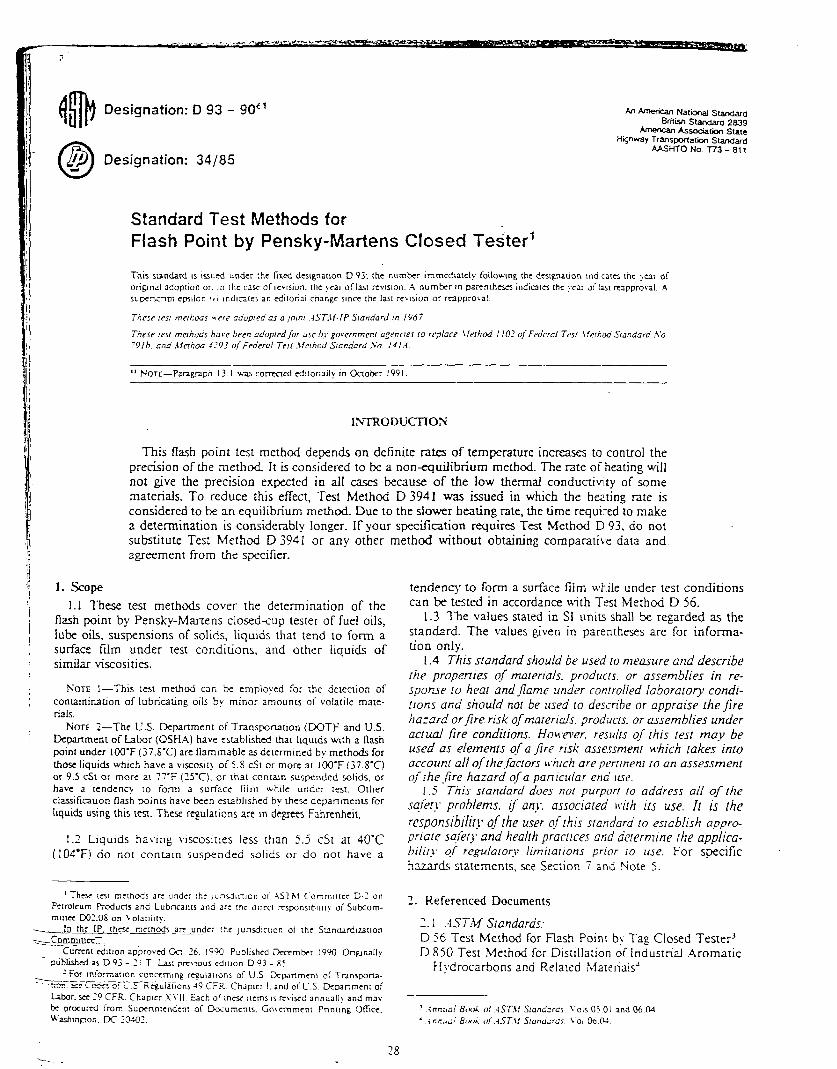
Standard Test Methods for Flash Point by Pensky-Martens Closed Tester’
” NOTE-Pangrapn 13.1 ua.5 com-crcd dtonally in Crtobcr 1991.
INTaODUCnON
This fIa.sh point test method depends on definite rates of temperature increases to control the precision of the method It is considered to be a non-equilibrium method. The rate of heating will not give the precision expected in all cases because of the low thermal conductivity of some materials. To reduce this effizt, Test Method D 3941 was issued in which the ha.ting rate is considered to be an equilibrium method Due to the slower heating rate, the time required to make a determination is considerably longer. If your specification requires Test Method D 93, do not substitute Test Method D 3941 or any other method without obtaining comparatire data and agreement from the specifier.
1. scope 1.1 These test methods cover the determination of the
flash point by Pensky-Martens closed<up tester of fuel oils, lube oils, suspensions of solids, liquids that tend to form a surface film under test conditions, and other liquids of similar viscosities.
NOTE l-This lesi meti& wn Se employed for rhe deleclion of contamination of lubricating oils by minor amourns of volatile mare- rials.
NOTE 2-The U.S. Depanmenr of Transponatlon (DOTF and U.S. Dcparrmenr of Labor (OSHA) have established rhat hqutds wth a flash point under ICKJ’F (37,s’C) are flammable as dcwmlned by methods for those liquids which have a viscosil! of 5.8 c.51 or more ar 100-F (37.8-C) or 9.5 cSt or more at 77-F (ZS’C). or that conwn suspended solids, or have a rendenc]. IO form a surface film while under I~SI. Other classificauon flash points have been cswbllshed by these departments for hquids using this resr. Thex rcgularlons are In dqrces Fahrenheit.
I.1 Liquids having viscosities less rhan 5.5 cSt at 40-C (104°F) do nor conza~n suspended solids or do nor have a
tendency to form a surface film wk.ile under test conditions can be tested in accordance with Test Method D 56.
1.3 The values stated in SI units shall be regarded as the standard. The values given in parentheses are for informa- tion only.
I .4 This standard should be used to measure and describe the propenies of materials. products. or assemblies in re- sponse to heat and /lame under controiied laboratory condi- tions and should not be used lo dewibe or appraise rhefire hazard or fire risk of marends. prodxts. OI assemblies under actual ./ire conditions. HoHxver. resuits o/ this test may be used as elemenrs qf a /ire risk assessment which rakes inro account all of rheJactors bc.hlch ure pertinent IO an assessment qf the.fire hazard o/a particular ena’ we.
I .S This standard does not purport to address all of the sqier!. problems. it’ an!.. associated wirh irs use. II is rhe rcsponsibiiif>- oilhe user q/rhu standard to establish appro- priate sqfety and health practrces and &termtne the applica- hifir!. C$ regulatoq, limtraltons prior IO use. For specific hazz.r& statements. see Section 7 and Note 5.
7,. Referenced Documents
2.1 .-ISTM Standards. D 56 Test Method for Rash Point by Tag Closed Tester3 D 850 Test Method for Distillation of industrial Aromatic
H>fdrocarbons and Related Materials”
28 -.. 7
. D 1015 Test Method for Freezing -Point of High-Purity
f
6. Apparatus Hydrocarbons3 6.1 Pmsky.lfotiens Closed Flash Tesrcr. as descriti in
D 1016 Ttstipftpm - -Annex A 1. Freezing Points3
- .__.
J-J 1078 Test, .Mettoc- fbr D-&i&%& -Kaj&- of Volatjle. _ 6.2 ThermomeIers-Three standard thermometers shall
or-5 be used with the ASTM Penskv-Martens tester as follows: - 6.X For tests in which theindicated reading falls uithin
Db3941 Tesr Method for Flash Point by the Equilibrium Method With a Closed Cup Apparatus”
I ‘~4057 Practice for Manual Sampling of Petroluem and
petroleum P&u&
the limits of 10 to 6O’C (50 to 140-F). inclusive, an ASTM 9C (9F) Pensky-Martens low range Thermometer haxiing a range from -5 to +I 10°C (20 to 23O’F) and conforming IO the requirements of Specification E I shall be used. Equally acceptable is IP thermometer 15C (I 5F), ,Airh specifications as shown in .4nnexes AZ and A3.
6.12 For tests in which the indicated reading falls uithin the limirs 60 to 140X (140 to 284’F). inclusive, an AST?cl 88C (88Fj Vegetable Oil Flash Thermometer having a range of 10 to 2Oo’C (50 to 392’F) and conforming to the requirements of Specification E 1 shall be used. Equally acceptable is IP thermometer IP IO I C.
62.3 For the range 60 IO i lO’C.( 140 to 230°F) either low or medium range thermometer may be used.
6.2.4 For tests in which the indicated reading falls within 130 to 37o’C (265 to 7oo’F) an ASTM 1OC (IOF) Pens&- Martens high-range Thermometer having a range from 90 to 370-C (200 to 7oo’F) and conforming to the requirements of Specification E I shall be used. E-qually acceptable is IP thermometer 16C (16F), with specifications as shown in Annex A3.
E 1 Specification for ASTM Thermometers’ .E 300 Practice for Sampling Industrial Chemicals8
I Terminology 3.1 Descriprion of a Tertn Specijic to This Srandard: 3. ].I jlosh poinl-the lowest temperature corrected to a irometric pressure of 10 1.3 kPa (760 mm Hg), at which ,plication of a test flame causes the vapor of a specimen to nite under specified conditions of test. 3.1.1.1 Discussion-The sample is deemed to have shed when a large ilame appears and instantaneously 3pagates itself over the surface of the sample. 3. I. 1.2 D~~czLssion-0ccasionatly, the application of the I flame will cause a blue halo or an enlarged flame. This nerally occurs near the actual flash point but in some -6, especially with halogenated hydrocarbons and admix- Fs. can occur at any temperature. The phenomena are i to be considered true flash points.
Summary of Test Methods
..I The sample is heated at a slow, constant rate with ,rinual nirting. A small flame is directed into the cup at Jlar intervals with simultaneous interruption of stirring. : flash point is the lowest temperature at which applica- : of the test flame causes the vapor above the sample to le.
Zgniticance and Use I Flash point measures tendency of the sample to form !mmable mixture with air under controlled laboratory jitions. II is only one of a number of propenics u,hich : be considered in assessing the overall flammabilit! rd of a material. 2 flash pain: is used in shipping and safety regulations :fine flammable and combustible materials. One should uli the particular regulation invol\.ed for precise dcfini- d these classes.
i Flash pc;nt can indicate the possible presence of !’ \olatile 2nd flammable materials in a rels~i\~el\~ olatile or nonflammable material. For example. an mall!- low flash point on a sample of kerosine can ale gasoline contaminafion.
This test method provides the oni\ closed cup flash ItsI procedures for remperalures to 27O’C (696-F).
:
6.2.5 For the range 130 to 140°C (265 to 285%) either the medium or high-range thermometer may be used.
NOTE 3-There are automatic flash poinr tcster~ arailable and in use that may be advantageous in that tie) save lesring time and erhjbil other factors which may merit their UC. In any casts oi dispure the flash poinf as determined manually is considered the referee test.
7. Hazards
7.1 The operator muSt exercise and take appropriate safet!. precautions during the initial application of the test flame, since samples containing loa--flash material can give an abnormally strong flash when rhe tesL flame is first applied.
8. Sampling
8.1 Erroneous]!- high flash points ma! he obtained if precautions are not taken to a\.oid the loss of vola:ile material. Do not open containers unnecessari!:. and mak: a transfer unless the sample temperalure is at I::ZSI the equila- lent of 8°C ( 1 S”F) below the expecred flash paini. Do noI us? ampies from leaky containers for these tesl methods.
8.2 Do not store samples in plastic (polyethylene. pal! propylene. etc.) conrainers. since \ ol3rile material ma! diffuse through the u,alls of the enclosure.
8..; Obtain a sample in accordance v,Ilh instructions gilen in Practice D 4057 or E 300.
S.4 Samples of vev viscous rateriais may be uarmed until the!. are reasonably fluid before the!- are lrned. Hou.ever. no sample should TV heated more than is abso- luteI!, nccessar_\‘. It shall net’er bz heared aho1.e a IempeErure of 17°C (30-F) belou ins expected flash polnl.
8.5 Samples containing dissol\-ed or free \:.Lier ma) be deh\dratcd L\.ith calcium chloride or b! fii:?ring through a qualilsri\-e filler paper or a loose $I+ o: do, absor&nr
29

cotton. Warming the UrnpIe is permittsj. but it should not be heated for prolonged pericds or above a temperature of 17°C (3O’F) below its expected flash point.
NOTE l-If the sample is 5u5cr;!~l of conra~nlng volatile :ontami- “an&. the treatment descnhd in 5 1Ind 9.5 should Ss ornlwd.
9. Preparation of .Ipparatus 9. i Support the tester on a Ie.Lel. steady uble. Unlsss :ssts
are made In a draft-free room or comparrmrnt. it is good pracrice. but not required. :n surround the tester on three sides hlth J shield. each sec::dn of uhich is about 150 mm (I 8 in.) WI& 2nd 600 mm (‘2 ln.1 hIsi.
SOTE S-C3utian-4tellculous 21tcnuon ;o li! c!c1a~is re!Jnng CO the ll3me exposure device. 5aze of rest (lame. rare 0i remvnrure mcre3.x. 2nd rate of dipplng rhe tlams ?.xpsure dellce I~IO :he vapor of ihe specimen is desirable for good results.
10. Calibration 10.1 Determine the flash point of pxylene9 (Warning-
See Note 6.), following the directions in Sections 9 through I I. When the tester is operating properly. a value of 27.2 ? l.I’C (81 ? 2’F) will be obtained.
NOTE 6: Warning-P-xylene U exrremely flammable. Harmful if inhaled. Keep away from heat. sparks and open flame. Keep container closed. Use with adequate ventilation. Avoid-buildup of vapors and eliminate all sources of ignition, especially non-explosion proof electric31 apparatus and heaters. Avoid bresthlng vapor or spray mist. Avoid prolonged or repeated contact with skin.
10.2 If the flash point obtained on pxvlene is not within the limits stated in 14.1.2, check the condi&a and operation of the apparatus to ensure conformity with the details listed in Annex Al, especially with regard to the tightness of the lid (A I. 1.2. I), the action of the shutter, and position of the test flame (A 1.1.X). After adjustment, if necessary, repeat the test. P-xylene having a flash point of 27.2 _+ I. I’C (8 I C 2-F) is not a suitable reference in the high temperature range of the Pensky-Manens Closed Tester which can be as high as 37O’C (700°F).
10.3 P-xylene shall conform to the following require- ments:
Soecilic Cnwty 15.56/l 5.56-c 0.864 m,n 0.866 max.
biling Range !‘C lrom rw 10 dp. p~znl uhen rnred in a~~orchce
with Tess bIcrhcd D 850 or D 1079. The range shall include Ihc ixahng w!nl ol pure p-xylcne which is 138.35-c (281.03-n.
PUfll? 95 5 ml”.. (TreerIng p01nt of I I.Jj-Cl. mtn calculared in xcordancc wtrh Tar Slcrhod D 1016. from rhc expcnmcnrall) dercrrnlncd frctrine point. measured by Tcsr Method D 1015.
PROCEDURE .4-DE-I-ER?4IN.477ON OF FLASH POINl- OF ORDLYARY LIQUIDS
I 1. Procedure
I 1. I Thoroughly clean and dp all parts of the cup and its -I- accessonesEf6re starting the test. being sure to remove any
f
solveii which had been used to clean the apparatus. Fill the cup with the sample to be tested to the level indicated by the
7‘ ..: ,:I OSausfaao~ pa~lcnc may bc obwlncd x Flssh Pam Check Fluld from rhc
7.; Spcclal Product Gv. Chemical &PC.. Phllll(x Pctrolcum Co.. Drawer 0. Borgcr. -1 i-
TX 79007.
filling mark. Place the lid on the cup and Set the latter i! stove. Be sure to have the locating or locking device pro, engaged. lnsen the thermometer. Bring the mare+al t tested and the tezter to a temperature of I j r j’C (( IO’FI or I !‘C (X”F) lower than the estimated flash p whichever is lower. Light the test flame and adjust it to 4 (%2 in.) in diameter. Supply the hear at such a rate tha temperature as indicated by the therrnoF=:er increases 6’C (9 to I I”F)iml n. Turn the stirrer 90 10 1’0 rpm. sti in a down\Lard direction.
I I.2 If the sample is kno\vn IO have a flash point of 1 (230°F) or be!ow. ~ppiy the test tlame \vhctn rhs temper. of the sample is from Ii’C (30°F) to ‘8°C (SO’F) be!ov e.xpesrrd flash point 2nd thereafter at a :emprraturs rez that is a multiple of I’C (3’F). .\ppl’; the test flam operating the mechanism on the cover \bhich control5 shutter and test flame burner so that the flame is lo\\ into the vapor space of the cup in 0.5 s. left in its low position for I s, and quickly?aised to its high position nor: stir the sample while applying the test ilame.
11.3 If the sample is known to have a flash point al Ilo’C (230°F) apply the test flame in the manner described at each temperature that is a multiple of 2’C (: beginining at a temperature of 17°C (30’F)‘,to 28°C (5 below the expectec! flash point.
NOTE 7-When te;ting materials to determine if volarile con nan& are present it is not necessary (0 adhere to the temperature I for initial flame application as stated in 1 I.2 and 11.3.
Il.4 Record as the observed flash point the tempera read on the thermometer at the time the test flame app - tion causes a distinct flash in the interior of the cup. Do confuse the true flash point with the bluish halo sometimes surrounds the test flame at applications preca the one that causes the actual flash.
PROCEDURE B-DETEWIINATION OF FLGH POINT SUSPENSIONS OF SOLIDS AND HIGHLY VISCOUS
hIXTERlALS
12. Procedure
12. I Bring the material to be tested and the tester t temperature of 15 5 5°C (60 + IO’F) or 11°C (20°F) lo than the estimated flash point, whichever is lower. Turn stirrer 250 ? IO rprn. stirring in a downward direction. R. the temperature throughout the duration of the test at a I
of not less than I nor more than 1.5”C (2 CO 3”FJ/min. M the exception of these requirements for rates of stirring : heating, proceed 35 prescribed in Section I 1.
13. Calculation and Report
13.1 Observe and record the ambient barometric press (Note 8) at the time of the test. When the pressure din from 101.3 kPa (760 mm Hg), cot-r&t the flash point follows:
Corrected fl;rsh point = C + 0.25 (101.3 - p) Corrected !l;sh point = F + 0.06 (760 - f) Corrected Ilash point = C + 0.033 (760 - f)
where:
C = observed flash point. ‘C. F = observed flash points. “F. P = ambient baromettic pressure, mm Hg. and

P = ambient barometric pressure. kPa. 13.2 Record the corrected flash point to the ~PI’SSL @.5’C
14. I .j Bins-The procedure of this test method has no J~~~~yl~~f!ash point un be defined only in terms ofa tst “.- V-N
(or IV. method. - 13.3 Report the recorded flash potnt as the. Pens& 14. I .4 The precision data is not known to have kn
>lartens Closed Cup Flash Potnt .GTM-D 9?1IS=%ookhe-- developed in accordance with Research Report D-Z- 1007. gmple tested. ’ rreclsr&%The precision of Test Procedure B as .-
;OTE S-The barometric pressur used in this caiculatloo is the
,mblenr pressure for the labor-atop at the time of tesr. klan) aneroid barometers. such a~ those used 31 weather statlons and airpons. xe
precorrected 10 g~vc sea level reading and would not gve rhe correct re3dlng for this lest.
1~. precision and Bias
14. I Precisl’on-The prectsron of Test Procedure .J, as determined by the statlsricd examinatron of the interlaboratory test results is as follows:
I 4. I. I Rcpealabriir)--The difference berween successi\.e results obtained bv the same operator wirh the same appa- ratus under constant operatmg conditions on identical test materials would, in the long run. in the normal and correct operation of the test method, exceed the following values in I case in 70.
Fish Potn~ Rang Rcpzxabllity MaWd ‘C rn ‘C (‘F)
S~spcns~ons or solids 35 10 43 (95 10 I II?) 2 (4) All orhcrs IO.4 (2101 and under 2 (Al
AboVC 104 (220) 5.5 (IO)
14.12 Reproducibiiily-The difference between two single and independent results obtained bv different opera- ton working in different laboratoties on identical material would, in the long run, exceed the following values only in 1 case in 20.
Malcnal
Supcnsions 0C solids All orhers
FLzsh Po~nr Range Rcproduclbliily ‘C (‘R ‘f (7)
35 IO 43 (95 IO I IO) 3.5 (61 104 (220) and under 3.5 (6)
AbwC 104 (220; 8.5 (IS)
determined by the statistical esamination of the interlabontory test results is .as follows:
14.2. I Repealabilirc-The difference between successive results obtained by the same operator with the same appa- ratus under constant operating conditions on identical test materials would. in the long run. in the normal and correct operation of the test me:hod. exceed the following value in 1 case in 20:
Repeatability 5°C (9’F) I4.2.1 Reprodrtcibi(ir~,-T~ie difference between 2 sinpie
and independent results obi.ained by different operators working in different laboratories on idenucal material would. in the long run, exceed the fo,Iowing value only in I case in 30.
Reproducibility 10°C (18’F-)
142.3 The procedure of this test method has no bias because flash point can be defined only in terms of a), test method.
142.4 The precision data is not known to have ‘*been developed in accordance with Research Repon D-2-1007.
14.3 The definition of repeatability and reproducibilitv given here represents different components of the variance of the test methods: those given in 14. I are derived from standards of ASTM Committee D-2 and the Institute of Petroleum. while those of 14.Z are from ASTM Committee D-2.
15. Keywords
15.1 flash point; flammability; Pensky-Martens closed cup

(Mandatory Information)
x1. APP.\RiTUS SPECIFICATIONS
.A I 1 .A r!pml assembly of the ag~ararus. zgs hexed. is cover, and stove conionning to the foilowing requiremene: shown In Fig. ,A I_ I. The ~~ppantus shall consist of a WI CUP.
HANOLf IC;T!ONALI
(uusr wi TIP c.i(PrY CL’P)
STIRREP DRIVE FLEXIBLE SHAFT
[PULLEY DRIVE OPTIONAL 1
FLAME iXP0SUK.C OEViCE SHUTTER OPERATING KNOB
THERMOMETER
ISTANCE PIECE
0
TEST CUP
F YIN THICKNESS ---,
OVER CUP AREA IE,METAL SURROUNDING / THE CUP
HEATER FLAME-;YFE -/
OR ELECiRIC RESISTANCE TYPE (FLAME TYPE SHOWNI
I mm I (in.)
mm I max ! @W / WW
A 1 437 ! 5.16 (0.172) ! (0.203)
6 4194 I 42.06 (1.651) ! (1.656) c 1.58 , 3.18 ~_ (0.062)~ L [email protected] 0
; 57.23 9.52 t
E 57 86 : (2.253) L. .I 1 w; _
F 1 635 i (0.25) j (. .I
NOTE-M assemtiy my tx poslttonecl edher qtIt Of k?fthdnded.
FIG. Al.1 Pensky-Maeem Closed F?ash Tester
32

,A 1.1. I Cup--The cup shall be of brass. or other nont-ust~ng metal of equivalent heat conductivity, and shall conform to the dimensional requirements in Fig. .i: 2. The-- flange 9-d k esyipped with devices for locating the position Of the CUP In the stove. A handle attached t-0 the ---_.~ - -~_ flange of the cup is a desirable accessory~.~~ - ..~ - nor be so heavy as to tip over the empty cup.
,A, 1. I .’ Cowr: A 1.1.2.1 cover Proper-The cover shown in Fig. Al.3
shall be of brass (A 1.1.1) and shall have a rim projecting downward almost to the flange of the cup. The rim shall fit [he outside of the CUP V&I a clearance not exceeding 0.36 ,,,m (0.014 in.) on the diameter. There shall be a locating or io&ng devtce. or both, engaging with a corresponding oe~-ics on the cup. The four openings in the cover, A. B, C. and D. are shown in Fig. A 1.3. The upper edge of the cup shall be in ClO!X COIltaCt with the inner face of the cover throughout its circumference.
,&I. I-2.2 Shulter-The cover shall be equipped with a brass (Section 3) shutter (Fig. A1.4), approximately 2.4 mm (VIZ in.) thick, operating on the plane of the upper surface of the cover. The shutter shall be so shaped and mounted that it
MANOLE OPTIONAL
J
mm (in.) Xl,” - VW (-1
79.0 79 e (3.11) (3.14) 10 (0 04) (. J 2.8 i:, (0 111 (0.14)
21.72 21.&: (0.855) (0.860)
4547 45 72 (1.790) (1.800) 50 72 5O.E (1.997) (2.002) 55.75 56.00 (2.195) (2.205)
3.8 4.0 (0.15) (0.16) 53 90 5402 (2.122) (2.727)
229 254 (0 090) (0.100)
FIG. Al.2 Test Cup
H p+-
I . / i-Ld
- mm ITdX
0 12.7 E 48 F 13.5
G 23.8 H 12 I 7.9
J 1227 K 16.38 L 18.65
13.5 5.6
14.3
24.6 2.0
12.32 16.64 19.45
WI PW (~I? (0.50) (O.ti, (0.19) (0.22) (0.53) (0.56) (0.94) ww (0.05) (0.08) (0.31) (- .I (0.483) (0.485) (0.645) (0.6!35) (0.73-q (0.766)
FIG. Al.3 Cover Proper
rotates on the-axis of the horizontal center of the cover between two stops, so placed, that when in one extreme position, the openings A, B, and C in the cover are compietely closed, and when in the other extreme position, these openings are completely opened. The mechanism operating the shutter should be of the spring type and constructed so that when at rest the shutter shall exactly close the three openings. When opemted to the other extreme, the three cover openings shall be exactly open and the tip of the exposure tube shall be fully depressed.
A 1.1.2.3 Flame-Exposure Device-The flame-exposure device (Fig. A1.4) shall have a tip with an opening 0.69 to 0.79 mm (0.027 IO 0.03 I in.) in diameter. This tip shall be made preferably of stainless steel, although it may be fabricated of ocher suitable metals. The flame-exposure
device shall be equipped with an operating mechanism which. when the shutter is in thfr open position, depresses the tip so that the center of the orifice is between the planes of the under and upper surfaces of the cover proper at a point on a radius passing through the center of the larger opening A (Fig. Al .3).
A I. 1.2.4 Pilor F/unze--A pilot flame shall be provided for automatic relighting of the exposure flame. A bead 4 mm (%2 in.) in diameter can be mounted on the cover so that the size of the test flame can be regulated by comparison. The tip
33

of the piiot flame shall have an opsnmg the same size as the rip of the flame exposure device (0.69 to 0.79 mm (0.027 to 0.03 1 in.) in diameter).
A 1.12. j Sfirring DmiL-r-The cover shall be equipped with a stirring device (Fig. A I .4) mounted in the center of the cover and carrying two 2-bladed metal propeilers. In Fig. A 1.1 lower propeller is designated by the letters f.. .\f. and .V. This propeller shall measure approximateiv 23 mm from rip to tip. with each of its two blades S mm in lclcrh with a pirch of 15”. The upper propeiler is dssignared by :hs le:ters .J. C,
and G. This propeller measures apProximardy 19 mm, tip to tip, each ofits two blades is ~SO 8 mm in width with a pitch of 45’. Bolh propellers are located on the stirrer shaft in such a manner that. when viewed from the bottom of the stirrer. the blades of one propeller are at 0 and I go’ while the blades of the other propeller are at 90 and 270’. .-\ srirrer shaft ma) be coupled to the motor by a flexible shaft or a suitabiz xrangrment of pulley-s.
Al. 1.2.6 Slow-Heat shall be supplied to the cup b: means of a properly designed stove which is equivaient to a::
FC'ME CXPCSirRE
GEVICE 7
THERMOMETER AOAPTOR
-COvEi? PROPER
TEST CUP - i- RIM OFCUP MUST BE IN CONTACT WITH THE INNER FACE OF COVER
THROUGWYJT ITS CIRCUMFERENCE
m m w
Ill!” max (mm) Imax) A 18.3 19.8 (0.7'1) ‘ (0.78) a 2 38 3.18 (0.094) (0.125) C 7.6 8.4 (0 30) (0.33)
F 20 0.69 28 0.79 (0 (0.027) 08) (0.111 (0.031) F 2.0 28 (0 w (0.11) r, 64 10.4 (0 211) (0 41) H 916 112 (0 38) (0.U) IA 43.0 46 0 V69l.-. (1.81) ! 5n 0 51.6 (1.9.7) (2 03 ___ -.--~
K 0.36
'i 22 (-- I .---p.o14r----
2.06 lo 0-W (0 08) - - c M 37.8 44.4 (1 2'5) - (1 75) N 76 8.4 (0 3% ----103331- -. .
* Indudes t*ance foe Lwgm of themKmwter gwec n Spm~carm E 1.
FIG. Al.4 Test Cup and Cover Assembly - -
34

air bath. The stove shall consist of an air bath and a top plate ,,n u hich the flange of the cup rests.
Al. 1.1.7 .4ir Barb-The air bath shall have a cylindrical ,nterior and shall coniom to the dimensional requirements ,n Fig. A 1.1. The air bath may be either a flame or ,=lecrrically heated metal castmg (X1.1.2.8). or an electric- r&stance element (A I. 1.2.9). In either case. the air bath rnust be suitabie for use at the tempentures to which it will b subjected without deformation.
.AI I .1.8 Hearer. Fiame or Eiecrrrc-If the heating ele- ment is a flame or an e!ecrtic heater. it shall be 50 designed 3nd used that the temperatures of the bottom and the walls are approximately the same. In order that (he air bath ,nremal SU~CCS should be a[ a uniform temperature, it should not be less than 5.4 mm (% in.) in thickness unless the beating element is designed to give equal heat flux densities over all the wall and bottom surfaces.
A I. 1.2.9 Hearer. Electric Resisrance-If the heater is of the electric resistance type, it_s_h_all be constructed so that all pans ~f-rhein~erioTmr;e~~e~-unif~~llli. The wall and bottom of the air bath-shall not be less than 6.-l mm (1~ in.) in thickness.unless -b rytance heating elements are
.d-VB&-all-the&nom of the air bath. A heater haking such a distribution of the heating elements positioned at least 4.0 mm (%z in.) away from the internal surface of the heating unit can be used in conjunction with a mmlmum thickness of 1.58 mm (‘116 in.) for the wall and bottom of the air bath.
A I. I .2. IO Top Plure--The top plate shall be of metal. and shall be mounted Nith ai7 air gap between it and the air bath. It may be attached to the air bath by means of three screws and spacing bushings. The bushings should bz of proper thickness to define an ar gap of 1.8 mm (!/I, in.), and they shall be not more than 9.5 mm (‘/a in. ) in diameter.
3s